CN1838971A - Direct mechanical ventricular assist device equipped with sensors and controlled by algorithms - Google Patents
Direct mechanical ventricular assist device equipped with sensors and controlled by algorithmsDownload PDFInfo
- Publication number
- CN1838971A CN1838971ACNA2004800237558ACN200480023755ACN1838971ACN 1838971 ACN1838971 ACN 1838971ACN A2004800237558 ACNA2004800237558 ACN A2004800237558ACN 200480023755 ACN200480023755 ACN 200480023755ACN 1838971 ACN1838971 ACN 1838971A
- Authority
- CN
- China
- Prior art keywords
- heart
- cup
- agents
- liner
- wall
- Prior art date
- Legal status (The legal status is an assumption and is not a legal conclusion. Google has not performed a legal analysis and makes no representation as to the accuracy of the status listed.)
- Pending
Links
Images


Classifications
- A—HUMAN NECESSITIES
- A61—MEDICAL OR VETERINARY SCIENCE; HYGIENE
- A61M—DEVICES FOR INTRODUCING MEDIA INTO, OR ONTO, THE BODY; DEVICES FOR TRANSDUCING BODY MEDIA OR FOR TAKING MEDIA FROM THE BODY; DEVICES FOR PRODUCING OR ENDING SLEEP OR STUPOR
- A61M60/00—Blood pumps; Devices for mechanical circulatory actuation; Balloon pumps for circulatory assistance
- A61M60/20—Type thereof
- A61M60/289—Devices for mechanical circulatory actuation assisting the residual heart function by means mechanically acting upon the patient's native heart or blood vessel structure, e.g. direct cardiac compression [DCC] devices
- A—HUMAN NECESSITIES
- A61—MEDICAL OR VETERINARY SCIENCE; HYGIENE
- A61M—DEVICES FOR INTRODUCING MEDIA INTO, OR ONTO, THE BODY; DEVICES FOR TRANSDUCING BODY MEDIA OR FOR TAKING MEDIA FROM THE BODY; DEVICES FOR PRODUCING OR ENDING SLEEP OR STUPOR
- A61M60/00—Blood pumps; Devices for mechanical circulatory actuation; Balloon pumps for circulatory assistance
- A61M60/50—Details relating to control
- A61M60/508—Electronic control means, e.g. for feedback regulation
- A61M60/515—Regulation using real-time patient data
- A61M60/531—Regulation using real-time patient data using blood pressure data, e.g. from blood pressure sensors
- A—HUMAN NECESSITIES
- A61—MEDICAL OR VETERINARY SCIENCE; HYGIENE
- A61M—DEVICES FOR INTRODUCING MEDIA INTO, OR ONTO, THE BODY; DEVICES FOR TRANSDUCING BODY MEDIA OR FOR TAKING MEDIA FROM THE BODY; DEVICES FOR PRODUCING OR ENDING SLEEP OR STUPOR
- A61M60/00—Blood pumps; Devices for mechanical circulatory actuation; Balloon pumps for circulatory assistance
- A61M60/10—Location thereof with respect to the patient's body
- A61M60/122—Implantable pumps or pumping devices, i.e. the blood being pumped inside the patient's body
- A61M60/165—Implantable pumps or pumping devices, i.e. the blood being pumped inside the patient's body implantable in, on, or around the heart
- A61M60/191—Implantable pumps or pumping devices, i.e. the blood being pumped inside the patient's body implantable in, on, or around the heart mechanically acting upon the outside of the patient's native heart, e.g. compressive structures placed around the heart
- A—HUMAN NECESSITIES
- A61—MEDICAL OR VETERINARY SCIENCE; HYGIENE
- A61M—DEVICES FOR INTRODUCING MEDIA INTO, OR ONTO, THE BODY; DEVICES FOR TRANSDUCING BODY MEDIA OR FOR TAKING MEDIA FROM THE BODY; DEVICES FOR PRODUCING OR ENDING SLEEP OR STUPOR
- A61M60/00—Blood pumps; Devices for mechanical circulatory actuation; Balloon pumps for circulatory assistance
- A61M60/40—Details relating to driving
- A61M60/465—Details relating to driving for devices for mechanical circulatory actuation
- A61M60/468—Details relating to driving for devices for mechanical circulatory actuation the force acting on the actuation means being hydraulic or pneumatic
- A—HUMAN NECESSITIES
- A61—MEDICAL OR VETERINARY SCIENCE; HYGIENE
- A61M—DEVICES FOR INTRODUCING MEDIA INTO, OR ONTO, THE BODY; DEVICES FOR TRANSDUCING BODY MEDIA OR FOR TAKING MEDIA FROM THE BODY; DEVICES FOR PRODUCING OR ENDING SLEEP OR STUPOR
- A61M60/00—Blood pumps; Devices for mechanical circulatory actuation; Balloon pumps for circulatory assistance
- A61M60/50—Details relating to control
- A61M60/508—Electronic control means, e.g. for feedback regulation
- A61M60/515—Regulation using real-time patient data
- A61M60/523—Regulation using real-time patient data using blood flow data, e.g. from blood flow transducers
- A—HUMAN NECESSITIES
- A61—MEDICAL OR VETERINARY SCIENCE; HYGIENE
- A61F—FILTERS IMPLANTABLE INTO BLOOD VESSELS; PROSTHESES; DEVICES PROVIDING PATENCY TO, OR PREVENTING COLLAPSING OF, TUBULAR STRUCTURES OF THE BODY, e.g. STENTS; ORTHOPAEDIC, NURSING OR CONTRACEPTIVE DEVICES; FOMENTATION; TREATMENT OR PROTECTION OF EYES OR EARS; BANDAGES, DRESSINGS OR ABSORBENT PADS; FIRST-AID KITS
- A61F2/00—Filters implantable into blood vessels; Prostheses, i.e. artificial substitutes or replacements for parts of the body; Appliances for connecting them with the body; Devices providing patency to, or preventing collapsing of, tubular structures of the body, e.g. stents
- A61F2/02—Prostheses implantable into the body
- A61F2/24—Heart valves ; Vascular valves, e.g. venous valves; Heart implants, e.g. passive devices for improving the function of the native valve or the heart muscle; Transmyocardial revascularisation [TMR] devices; Valves implantable in the body
- A61F2/2478—Passive devices for improving the function of the heart muscle, i.e. devices for reshaping the external surface of the heart, e.g. bags, strips or bands
- A61F2/2481—Devices outside the heart wall, e.g. bags, strips or bands
- A—HUMAN NECESSITIES
- A61—MEDICAL OR VETERINARY SCIENCE; HYGIENE
- A61M—DEVICES FOR INTRODUCING MEDIA INTO, OR ONTO, THE BODY; DEVICES FOR TRANSDUCING BODY MEDIA OR FOR TAKING MEDIA FROM THE BODY; DEVICES FOR PRODUCING OR ENDING SLEEP OR STUPOR
- A61M2205/00—General characteristics of the apparatus
- A61M2205/32—General characteristics of the apparatus with radio-opaque indicia
- A—HUMAN NECESSITIES
- A61—MEDICAL OR VETERINARY SCIENCE; HYGIENE
- A61M—DEVICES FOR INTRODUCING MEDIA INTO, OR ONTO, THE BODY; DEVICES FOR TRANSDUCING BODY MEDIA OR FOR TAKING MEDIA FROM THE BODY; DEVICES FOR PRODUCING OR ENDING SLEEP OR STUPOR
- A61M2205/00—General characteristics of the apparatus
- A61M2205/33—Controlling, regulating or measuring
- A61M2205/3303—Using a biosensor
- A—HUMAN NECESSITIES
- A61—MEDICAL OR VETERINARY SCIENCE; HYGIENE
- A61M—DEVICES FOR INTRODUCING MEDIA INTO, OR ONTO, THE BODY; DEVICES FOR TRANSDUCING BODY MEDIA OR FOR TAKING MEDIA FROM THE BODY; DEVICES FOR PRODUCING OR ENDING SLEEP OR STUPOR
- A61M2205/00—General characteristics of the apparatus
- A61M2205/33—Controlling, regulating or measuring
- A61M2205/3331—Pressure; Flow
- A61M2205/3334—Measuring or controlling the flow rate
- A—HUMAN NECESSITIES
- A61—MEDICAL OR VETERINARY SCIENCE; HYGIENE
- A61M—DEVICES FOR INTRODUCING MEDIA INTO, OR ONTO, THE BODY; DEVICES FOR TRANSDUCING BODY MEDIA OR FOR TAKING MEDIA FROM THE BODY; DEVICES FOR PRODUCING OR ENDING SLEEP OR STUPOR
- A61M2230/00—Measuring parameters of the user
- A61M2230/04—Heartbeat characteristics, e.g. ECG, blood pressure modulation
- A—HUMAN NECESSITIES
- A61—MEDICAL OR VETERINARY SCIENCE; HYGIENE
- A61M—DEVICES FOR INTRODUCING MEDIA INTO, OR ONTO, THE BODY; DEVICES FOR TRANSDUCING BODY MEDIA OR FOR TAKING MEDIA FROM THE BODY; DEVICES FOR PRODUCING OR ENDING SLEEP OR STUPOR
- A61M2230/00—Measuring parameters of the user
- A61M2230/20—Blood composition characteristics
- A61M2230/202—Blood composition characteristics partial carbon oxide pressure, e.g. partial dioxide pressure (P-CO2)
- A—HUMAN NECESSITIES
- A61—MEDICAL OR VETERINARY SCIENCE; HYGIENE
- A61M—DEVICES FOR INTRODUCING MEDIA INTO, OR ONTO, THE BODY; DEVICES FOR TRANSDUCING BODY MEDIA OR FOR TAKING MEDIA FROM THE BODY; DEVICES FOR PRODUCING OR ENDING SLEEP OR STUPOR
- A61M2230/00—Measuring parameters of the user
- A61M2230/20—Blood composition characteristics
- A61M2230/205—Blood composition characteristics partial oxygen pressure (P-O2)
- A—HUMAN NECESSITIES
- A61—MEDICAL OR VETERINARY SCIENCE; HYGIENE
- A61N—ELECTROTHERAPY; MAGNETOTHERAPY; RADIATION THERAPY; ULTRASOUND THERAPY
- A61N1/00—Electrotherapy; Circuits therefor
- A61N1/02—Details
- A61N1/04—Electrodes
- A61N1/05—Electrodes for implantation or insertion into the body, e.g. heart electrode
Landscapes
- Health & Medical Sciences (AREA)
- Engineering & Computer Science (AREA)
- Heart & Thoracic Surgery (AREA)
- Cardiology (AREA)
- Hematology (AREA)
- Veterinary Medicine (AREA)
- Anesthesiology (AREA)
- Biomedical Technology (AREA)
- Mechanical Engineering (AREA)
- Life Sciences & Earth Sciences (AREA)
- Animal Behavior & Ethology (AREA)
- General Health & Medical Sciences (AREA)
- Public Health (AREA)
- Medical Informatics (AREA)
- Vascular Medicine (AREA)
- External Artificial Organs (AREA)
- Prostheses (AREA)
- Infusion, Injection, And Reservoir Apparatuses (AREA)
- Medicines That Contain Protein Lipid Enzymes And Other Medicines (AREA)
Abstract
Description
Translated fromChinese本发明在一个实施例中涉及用来辅助脆弱心脏以提供所需的血液泵送的装置,更具体地涉及一种机械式心脏辅助装置,其包围了心脏并对心脏施加周期性的集中液压力,以便以正确的顺序和强度来驱动心室动作(压缩和膨胀)。The present invention, in one embodiment, relates to a device for assisting a fragile heart to provide the required pumping of blood, and more particularly to a mechanical heart assist device that surrounds the heart and applies periodic focused hydraulic pressure to the heart , in order to drive the ventricular actions (compression and expansion) in the correct sequence and intensity.
技术领域technical field
用于通过提供正确的收缩和舒张促动以及循环功能来辅助人体心脏的机械装置。A mechanical device used to assist the human heart by providing correct systolic and diastolic actuation and circulatory function.
背景技术Background technique
用于心脏泵送功能出现故障的病人的传统医学和外科医疗限于血液接触式装置,它们在技术上很难安装,并且会导致与这种血液接触相关的并发症以及装置安装的技术问题。心脏输出不足仍然是导致美国每年数百万死亡案例的原因。对于一些亚急性和慢性形式的低心脏输出来说,机械装置被证明是一种实用的治疗方案。然而,所有目前可得到的装置都需要很长的时间来植入,这在紧急的恢复呼吸情况下是没有价值的,导致在能够提供足够的循环支持之前便已丧失生命。此外,类似于本发明的其它非血液接触式装置无法提供足够增强的心脏功能。机械式心脏辅助装置一般通过向循环系统提供血液泵送支持来工作,以便辅助出现了故障的心脏。Conventional medical and surgical care for patients with cardiac pump failures is limited to blood-contacting devices, which are technically difficult to install and lead to complications related to such blood contact and technical problems in device installation. Insufficient cardiac output remains the cause of millions of deaths each year in the United States. Mechanical devices have proven to be a practical treatment option for some subacute and chronic forms of low cardiac output. However, all currently available devices take a long time to implant, which is of no value in emergency recovery breathing situations, resulting in loss of life before adequate circulatory support can be provided. Furthermore, other non-blood-contacting devices similar to the present invention do not provide sufficient enhancement of cardiac function. Mechanical heart assist devices generally work by providing blood pumping support to the circulatory system in order to assist a malfunctioning heart.
已经介绍并研究了通过压缩其外部的心外膜面来辅助心脏功能的多种机械式技术。这些方法集中在通过辅助心脏的收缩(正泵送)功能来提高心脏性能。这种技术已经被描述为“直接心脏压缩”(DCC)。DCC方法仅在实验室条件中进行了研究,就申请人所知,这种装置并未用于人体受检者。关于DCC的研究主要集中在左心室(LV)的收缩和舒张性能上。DCC技术的例子包括但不限于心肌移植术(将骨骼肌缠绕在心脏周围并对其进行人工刺激的技术)、心脏支撑系统(美国新泽西州Pinebrook的Heart Technologies公司)和“Heart Booster”(美国马萨诸塞州Danvers的Abiomed公司)。采用这些装置的实验室研究的总体结果导致了类似的发现。具体地说,已经表明,DCC可以增强左心室(LV)的泵送功能,同时LV氧气消耗的原本需求没有任何明显变化;因此,已经表明,DCC可以改善LV的泵送功能,而不会增强心肌的氧气消耗和/或要求来自心脏的额外作功。Various mechanical techniques to assist heart function by compressing its outer epicardial surface have been described and studied. These approaches focus on improving cardiac performance by assisting the heart's systolic (positive pumping) function. This technique has been described as "direct cardiac compression" (DCC). The DCC method has only been studied in laboratory conditions and, to the applicant's knowledge, this device has not been used on human subjects. Research on DCC has mainly focused on the systolic and diastolic properties of the left ventricle (LV). Examples of DCC techniques include, but are not limited to, cardiac transplantation (a technique in which skeletal muscle is wrapped around the heart and artificially stimulated), cardiac support systems (Heart Technologies, Pinebrook, NJ, USA), and the "Heart Booster" (Massachusetts, USA) Abiomed, Danvers, State). Overall results from laboratory studies employing these devices have led to similar findings. Specifically, DCC has been shown to enhance left ventricular (LV) pumping without any apparent change in the original demand for LV oxygen consumption; thus, DCC has been shown to improve LV pumping without enhancing Oxygen consumption of the myocardium and/or additional work required from the heart.
已经表明,DCC装置只能使具有相当大程度LV衰竭的心脏受益。具体地说,DCC技术只能在中度到重度心力衰竭的情形下明显改善心脏的收缩功能。另外,DCC技术在应用于相对膨胀或扩张的LV时效果更明显。因此,在心力衰竭恶化以及心脏因心力衰竭而扩张或膨胀时,DCC所提供的这种辅助的相对程度提高。显然,DCC技术对舒张功能(RV和LV的舒张功能)有负面影响。这表现为舒张容积减小,这至少部分地说明,对于并未至少达中度衰竭的心脏来说,DCC无法对其提供有效的增强。这还说明了DCC的功效受限于LV尺寸和/或扩张的充分程度,并且比较依赖于预加载和/或心室的充盈压力。因此,DCC要求有“足够”程度的心脏病和/或心力衰竭,以便给心脏的功能带来好处。另外,DCC装置对舒张松弛的动态特性有负面影响,并且实际上降低了舒张压的下降率(负的最大dP/dt),延长了心室松弛所需的时间。这更好地说明了为何DCC技术要求有较大程度的LV和RV负荷(即增加的左和右心房压力或“预加载”)才能有效果,这是因为这种增加可用于提高心室的充血。后一点对于较小的心脏尺寸和/或较少的心室膨胀而言尤其成立。It has been shown that DCC devices can only benefit hearts with a considerable degree of LV failure. Specifically, DCC technology can only significantly improve the systolic function of the heart in the case of moderate to severe heart failure. In addition, the DCC technique is more effective when applied to relatively dilated or dilated LVs. Thus, the relative degree of this assistance provided by the DCC increases as heart failure worsens and the heart becomes dilated or distended due to heart failure. Clearly, the DCC technique has a negative impact on diastolic function (diastolic function of the RV and LV). This was manifested as a reduction in diastolic volume, which at least partially explains the inability of DCC to provide effective augmentation to a heart that has not reached at least moderate failure. This also suggests that the efficacy of DCC is limited by LV size and/or adequacy of dilation and is relatively dependent on preload and/or ventricular filling pressure. Therefore, DCC requires a "sufficient" degree of heart disease and/or heart failure to confer a benefit on heart function. In addition, the DCC device negatively affects the dynamic properties of diastolic relaxation and actually reduces the rate of diastolic pressure drop (negative maximal dP/dt), prolonging the time required for ventricular relaxation. This better explains why the DCC technique requires a greater degree of LV and RV loading (i.e., increased left and right atrial pressure or "preload") to be effective, since this increase can be used to improve ventricular hyperemia . The latter point is especially true for smaller heart sizes and/or less ventricular distension.
DCC方法的关键缺陷是多因素的,其部分地概括于下述讨论中。首先,最主要的是,这些技术不能提供任何手段来增强克服“有效地”提高了心室刚性的其固有缺陷所需的心脏的舒张功能。这由在应用DCC的期间端部-舒张压-容积关系(EDPVR)中的左移来显示。对EDPVR的这一影响可在处于辅助或无辅助模式下的DCC装置中看到。显然,RV舒张功能因DCC而在很大程度上被削弱,这是因为RV壁和内腔压力的本质。此外,DCC装置全都忽略了这些技术对右心室动态特性、隔膜运动和整体心脏功能的相干和相关的影响。由于右心室负责向左心室提供“起动”血流,因此在使用这些与负荷有关的装置时,损害右心室功能就必然具有对左心室泵送功能的次要但负面的影响。此外,心室隔膜位于左、右心室之间,并且直接受到施加在RV和LV上的相关力的影响。DCC装置的另一有关的基本缺陷是,它们无法连续地监测心室壁的运动和心室的动态特性,而这对优化以复杂且内在相关的方式工作的左右心室上的这种机械动作所提供的辅助来说是在直观上很关键的。最后,关于DCC方法的研究无法充分地检查这些装置对心肌整体性的影响。The key drawbacks of the DCC method are multifactorial, which are summarized in part in the discussion below. First and foremost, these techniques do not provide any means to enhance the diastolic function of the heart required to overcome its inherent deficiency of "effectively" increasing ventricular stiffness. This is shown by a left shift in the end-diastolic pressure-volume relationship (EDPVR) during application of DCC. This effect on EDPVR can be seen in DCC devices in assisted or unassisted mode. Clearly, RV diastolic function is largely impaired by DCC due to the nature of RV wall and lumen pressures. Furthermore, DCC devices all ignore the coherent and relevant impact of these techniques on right ventricular dynamics, diaphragm motion, and overall cardiac function. Since the RV is responsible for providing "priming" blood flow to the LV, impairment of RV function necessarily has a secondary but negative impact on LV pumping function when using these load-dependent devices. Furthermore, the ventricular septum is located between the left and right ventricles and is directly affected by the relative forces exerted on the RV and LV. Another related fundamental flaw of DCC devices is their inability to continuously monitor the motion of the ventricular wall and the dynamic properties of the ventricle, which provides the necessary support for optimizing this mechanical action on the left and right ventricles working in a complex and intrinsically related manner. Assistance is intuitively critical. Finally, studies on DCC methods have not adequately examined the effects of these devices on myocardial integrity.
直接机械式心室辅助装置(下面简称为DMVA)是机械式心脏辅助装置的一种类型的例子。通常来说,DMVA系统包括两个主要元件:(a)杯形件,其具有一定的动态特性和材料构造,能够在整个收缩和舒张促动期间保持该装置的促动衬垫薄膜或膜片与心脏的外表面(心外膜)紧密相符,以及(b)驱动系统和控制系统的组合体,其可周期性地对位于杯形件内表面上的压缩和膨胀用衬垫薄膜施加流体压力,从而在收缩和舒张促动期间增加心脏的正常压力和容积偏差。装置的循环动作在心脏的左、右心室上施加周期性的推拉。A Direct Mechanical Ventricular Assist Device (hereinafter referred to as DMVA) is an example of one type of mechanical heart assist device. Generally speaking, a DMVA system consists of two main elements: (a) a cup with dynamic properties and material configuration capable of retaining the device's actuation liner membrane or diaphragm throughout systolic and diastolic actuation closely conforms to the outer surface of the heart (epicardium), and (b) a combination of drive system and control system that periodically applies fluid pressure to a compression and expansion cushion membrane on the inner surface of the cup , thereby increasing the heart's normal pressure and volume deviations during systolic and diastolic actuation. The cyclic action of the device exerts a periodic push and pull on the left and right ventricles of the heart.
通过以适当的频率和幅度来提供这种周期性运动,虚弱、衰竭、心室纤维性颤动或心搏停止的心脏便被驱动,而以大致接近正常功能心脏所产生的血流的方式来泵送血液。向内推动心脏外部壁会将左、右心室压缩成收缩构造,从而提高泵送功能。结果,血液就从心室排到循环系统中。紧接于每次收缩促动之后,循环的第二阶段对衬垫薄膜施加负压力,通过在心脏外部壁上施加拉力而使心室回到舒张构造。这称为舒张促动,允许心室被充盈血液以进行下次收缩。By providing this periodic motion at an appropriate frequency and amplitude, a weakened, failing, ventricular fibrillating, or asystolic heart is driven to pump blood in a manner that approximately approximates that produced by a normally functioning heart blood. Pushing the outer walls of the heart inward compresses the left and right ventricles into a contracted configuration, improving pumping function. As a result, blood is drained from the ventricles into the circulatory system. Immediately after each systolic actuation, the second phase of the cycle exerts negative pressure on the cushion membrane, bringing the ventricles back to the diastolic configuration by exerting a pulling force on the outer wall of the heart. This is called diastolic activation and allows the ventricles to be filled with blood for the next contraction.
在本发明的优选实施例中,通常利用顶端真空辅助、即施加在杯形件顶端上的真空来将杯形件安装在心脏上。这种优选实施例能够以无创和技术上简单的手段在病人体内将杯形件装置连接到心脏上,并且促进舒张促动。为了安装杯形件,利用胸部切开而露出心脏。杯形件位于心脏顶端之上的位置中,使得心脏顶端部分地插入到其中。对杯形件的顶端施加真空,从而将心脏和杯形件拉到一起,因此杯形件和心脏的顶端、杯形件的内壁以及心脏的心外膜面基本上相连。如果该特定杯形件实施例包括任何额外的检测或操作装置(通常集成在一根接口电缆中),那么之后便完成这类装置的连接。这一过程可在数分钟内完成,并且很容易教会缺乏外科实践的个人。In a preferred embodiment of the invention, the cup is typically mounted on the heart using tip vacuum assist, ie a vacuum applied to the tip of the cup. This preferred embodiment enables a non-invasive and technically simple means of attaching the cup device to the heart in a patient and facilitates diastolic actuation. To install the cup, a chest incision is used to expose the heart. The cup is located in a position over the apex of the heart such that the apex of the heart is partially inserted therein. A vacuum is applied to the apex of the cup, thereby drawing the heart and cup together so that the cup is substantially attached to the apex of the heart, the inner wall of the cup, and the epicardial surface of the heart. If the particular cup embodiment includes any additional sensing or operating devices (typically integrated in an interface cable), then the connection of such devices is then completed. The procedure can be performed in minutes and is easily taught to individuals who lack surgical practice.
有效的DMVA要求杯形件和驱动系统能够满足多种且复杂的性能要求。本发明杯形件的优选实施例可以优于现有技术DMVA装置的方式,来满足这些关键性能要求。Effective DMVA requires cups and drive systems capable of meeting diverse and complex performance requirements. Preferred embodiments of the cup of the present invention can meet these critical performance requirements in a manner superior to prior art DMVA devices.
迄今为止,有多项专利和公开出版物公开了直接机械式心室辅助装置和其它的心脏辅助装置,相关的一部分简要地概括如下:To date, there are a number of patents and publications disclosing direct mechanical ventricular assist devices and other cardiac assist devices, some of which are briefly summarized below:
授予Vineberg的美国专利2826193公开了一种通过柔性拉带固定在心脏上的心室辅助装置。Vineberg采用机械泵送来为心脏提供收缩压力,以便辅助心脏的泵送动作。US Patent 2,826,193 to Vineberg discloses a ventricular assist device secured to the heart by flexible drawstrings. Vineberg uses mechanical pumping to provide systolic pressure to the heart to assist the heart's pumping action.
授予Hewson的美国专利3034501公开了一种类似的心室辅助装置,其由硅酮构成,并允许在心脏的不同部分上施加变化的压力。US Patent 3,034,501 to Hewson discloses a similar ventricular assist device that is constructed of silicone and allows varying pressures to be applied to different parts of the heart.
授予Smith的美国专利3053249公开了一种能够将收缩压力输送给心脏的心室辅助装置。Smith的装置利用胶带来将装置连接到心脏上。US Patent 3,053,249 to Smith discloses a ventricular assist device capable of delivering systolic pressure to the heart. Smith's device utilizes adhesive tape to attach the device to the heart.
授予Bolie的美国专利3233607公开了一种直接辅助装置,其可根据例如锻炼时产生的血流变化来改变收缩压力的水平。Bolie的装置要求进行完全地植入。授予Bolie的美国专利3449767公开了一种用于控制输送到可控制DMVA单元上的气囊的压力的系统。US Patent 3,233,607 to Bolie discloses a direct assist device that changes the level of systolic pressure in response to changes in blood flow, eg, during exercise. Bolie's device requires full implantation. US Patent 3449767 to Bolie discloses a system for controlling the pressure delivered to a balloon on a controllable DMVA unit.
授予Kline的美国专利3279464讲述了一种制造心室辅助装置的方法。Kline的装置仅将收缩压力提供给心脏。US Patent 3,279,464 to Kline teaches a method of making a ventricular assist device. Kline's device delivers only systolic pressure to the heart.
授予Heid的美国专利3371662公开了一种箍带形式的心室辅助装置。该箍带可植入有去纤颤电极。US Patent 3,371,662 to Heid discloses a ventricular assist device in the form of a cuff. The cuff may be implanted with defibrillation electrodes.
授予Kolobow的美国专利3376863显示了一种可将收缩压力输送给心脏的心室辅助装置。Kolobow的装置具有处于装置开口的周边附近的可膨胀轴环。心脏可通过使轴环膨胀而密封在装置中。US Patent 3,376,863 to Kolobow shows a ventricular assist device that delivers systolic pressure to the heart. The Kolobow device has an expandable collar near the periphery of the device opening. The heart can be sealed in the device by expanding the collar.
授予Anstadt的美国专利3455298公开了一种能够输送收缩和舒张压力的直接机械式心室辅助装置。舒张动作可通过使用真空来实现。副真空源用于将装置固定在心脏上。Anstadt还在美国专利5199804中进一步定义了该装置的几何形状。该发明的几何形状被描述为可容纳不同尺寸的心脏,并且防止心脏在气囊的压缩膨胀期间从装置中出来。US Patent 3,455,298 to Anstadt discloses a direct mechanical ventricular assist device capable of delivering both systolic and diastolic pressures. The diastolic action can be achieved through the use of vacuum. A secondary vacuum source is used to secure the device to the heart. Anstadt further defines the geometry of the device in US Patent 5,199,804. The geometry of the invention is described as accommodating hearts of different sizes and preventing the heart from coming out of the device during compression and expansion of the balloon.
授予Rassman的美国专利3478737公开了一种箍带形式的心室辅助装置。US Patent 3,478,737 to Rassman discloses a ventricular assist device in the form of a cuff.
授予Sausee的美国专利3513836公开了一种心室辅助装置,其通过多个气囊来将收缩压力输送给心脏。增加选定气囊中的压力可优先地对心脏的选定部分施压。US Patent 3,513,836 to Sausee discloses a ventricular assist device that delivers systolic pressure to the heart via a plurality of balloons. Increasing pressure in selected balloons preferentially pressurizes selected portions of the heart.
授予Schiff的美国专利3587567公开了一种直接机械式心室辅助装置,其能够将收缩和舒张压力都输送给心脏。该装置还包括允许心脏去纤颤的电极。装置通过也提供给舒张动作的中度真空压力而固定在心脏上。US Patent 3,587,567 to Schiff discloses a direct mechanical ventricular assist device capable of delivering both systolic and diastolic pressures to the heart. The device also includes electrodes that allow defibrillation of the heart. The device is secured to the heart by a moderate vacuum pressure that is also provided for the diastolic action.
授予Schiff的美国专利3613672公开了一种带有柔性外壳的杯形件,其允许通过相对较小的外科切开术来插入装置。该专利还公开了与杯形件相结合地使用传感器,例如心电图设备。还可参阅也授予Schiff的美国专利3590815和3674381。US Patent 3,613,672 to Schiff discloses a cup with a flexible housing that allows insertion of the device through a relatively small surgical incision. The patent also discloses the use of a sensor, such as an electrocardiogram device, in combination with the cup. See also US Patents 3,590,815 and 3,674,381, also to Schiff.
授予Goetz的美国专利4048990公开了一种可将收缩和舒张压力都输送给心脏的心室辅助装置。Goetz装置的外壳是可充气的,以便以最小的创伤将其安装到病人身上。US Patent 4,048,990 to Goetz discloses a ventricular assist device that delivers both systolic and diastolic pressures to the heart. The outer shell of the Goetz device is inflatable to allow for minimal trauma to install it on the patient.
授予Freeman的美国专利4448190公开了一种通过物理式连接到心脏上的带子来将收缩压力输送给心脏的心室辅助装置。在授予Heilman的美国专利5383840和5558617中公开了类似的装置。Heilman的专利公开了使用去纤颤装置,以及可促进组织向内生长以帮助将装置附着在心脏上的材料。US Patent 4448190 to Freeman discloses a ventricular assist device that delivers systolic pressure to the heart through a band physically attached to the heart. Similar devices are disclosed in US Patents 5,383,840 and 5,558,617 to Heilman. The Heilman patent discloses the use of a defibrillation device, and a material that promotes tissue ingrowth to help attach the device to the heart.
授予Parravicini的美国专利4536893公开了一种箍带形式的心室辅助装置,其可对心脏的选定部分施加压力。该专利还公开了与杯形件相结合地使用传感器,例如心电图设备。US Patent 4,536,893 to Parravicini discloses a ventricular assist device in the form of a cuff that applies pressure to selected portions of the heart. The patent also discloses the use of a sensor, such as an electrocardiogram device, in combination with the cup.
授予Sharma的美国专利4621617公开了一种其中心脏被放在两块金属板内的心室辅助装置。电磁场将金属板拉到一起,因而压缩了心脏。US Patent 4621617 to Sharma discloses a ventricular assist device in which the heart is placed within two metal plates. The electromagnetic field pulls the metal plates together, compressing the heart.
授予Snyders的美国专利4684143公开了一种具有可折叠外壳的心室辅助装置。这种装置可以最小的创伤安装到病人身上。还可参阅也授予Snyders的美国专利5169381和5256132。US Patent 4,684,143 to Snyders discloses a ventricular assist device with a collapsible housing. The device can be fitted to the patient with minimal trauma. See also US Patents 5,169,381 and 5,256,132, also issued to Snyders.
授予Stephenson的美国专利4979936公开了一种完全植入的心室辅助装置。Stephenson的装置包括与第二气囊流体式相连的第一气囊。第一气囊设置在肌肉中,而第二气囊公开为处于心脏附近或周围。然后使该肌肉电致收缩,因而迫使流体流出第一气囊并流入第二气囊。因此,第二气囊的膨胀便压缩了心脏。US Patent 4,979,936 to Stephenson discloses a fully implanted ventricular assist device. The Stephenson device includes a first balloon in fluid communication with a second balloon. The first balloon is disposed in the muscle, while the second balloon is disclosed near or around the heart. The muscle is then electrically contracted, thereby forcing fluid out of the first air sac and into the second air sac. Thus, inflation of the second balloon compresses the heart.
授予Lee的美国专利5273518公开了一种类似于上述肌肉促动式装置的完全植入的心室辅助装置。授予Grandjean的美国专利5098442和5496353、授予Neisz的美国专利5562595、授予Francischelli的美国专利5658237、5697884和5697952、授予Bourgeois的美国专利5716379和授予Chiu的美国专利5429584都公开了类似的装置。授予Guiraudon的美国专利5364337公开了一种控制肌肉动作的装置,其中该肌肉又可控制心脏的收缩。US Patent 5,273,518 to Lee discloses a fully implanted ventricular assist device similar to the muscle-actuated device described above. US Patents 5,098,442 and 5,496,353 to Grandjean, US Patent 5,562,595 to Neisz, US Patents 5,658,237, 5,697,884, and 5,697,952 to Francischelli, US Patent 5,716,379 to Bourgeois, and US Patent 5,429,584 to Chiu all disclose similar devices. US Patent 5,364,337 to Guiraudon discloses a device for controlling the action of a muscle which in turn controls the contraction of the heart.
授予Heilman的美国专利5098369公开了一种心室辅助装置,其由允许组织向内生产的材料构成,从而将装置附着在心脏上。还公开了使用去纤颤电极和心电图。US Patent 5,098,369 to Heilman discloses a ventricular assist device constructed of a material that allows tissue to grow inward, thereby attaching the device to the heart. The use of defibrillation electrodes and an electrocardiogram is also disclosed.
授予Grooters美国专利5131905公开了一种可对心脏施加收缩压力的心室辅助装置。Grooters装置通过多条带子固定在心脏周围的位置。US Patent 5,131,905 to Grooters discloses a ventricular assist device that applies systolic pressure to the heart. The Grooters device is held in place around the heart by multiple straps.
授予Wilk的美国专利5385528、5533958、5800334和5971911公开了一种适用于紧急抢救的直接机械式心室辅助装置。该可膨胀装置可在紧急抢救情况下通过较小的切开术便快速地安装好。授予Fogarty的美国专利6059750公开了类似的装置。US Patent Nos. 5,385,528, 5,533,958, 5,800,334 and 5,971,911 to Wilk disclose a direct mechanical ventricular assist device suitable for emergency rescue. The expandable device can be quickly installed through a minor incision in emergency rescue situations. US Patent 6,059,750 to Fogarty discloses a similar device.
授予Rosenberg的美国专利5713954公开了一种箍带形式的心室辅助装置,其可为心脏提供收缩压力。所公开的箍带适用于向心脏的指定部分施加压力,可安装有EKG传感器并且完全植入。US Patent 5,713,954 to Rosenberg discloses a ventricular assist device in the form of a cuff that provides systolic pressure to the heart. The disclosed cuff is adapted to apply pressure to a designated portion of the heart, can be fitted with an EKG sensor and is fully implantable.
授予Kovacs的美国专利5738627和5749839公开了一种直接机械式心室辅助装置,其可为心脏提供收缩和舒张压力。所公开的杯形件通过真空附着在心脏上,该真空还为心脏提供舒张压力。该装置的开口装有可膨胀的轴环。轴环在膨胀时可提供密封,以便辅助建立真空。US Patents 5,738,627 and 5,749,839 to Kovacs disclose a direct mechanical ventricular assist device that provides systolic and diastolic pressures to the heart. The disclosed cup is attached to the heart by a vacuum that also provides diastolic pressure to the heart. The opening of the device is fitted with an expandable collar. The collar provides a seal when inflated to assist in creating a vacuum.
授予Brennan的美国专利6076013公开了一种杯形件,其可检测心脏内的电活动,并且提供电刺激以便在心脏收缩时给予帮助。US Patent 6,076,013 to Brennan discloses a cup that detects electrical activity within the heart and provides electrical stimulation to assist the heart when it contracts.
授予Renirie的美国专利6110098公开了一种方法,其用于通过使用亚音速波来对心室纤颤或心律失齐提供治疗。US Patent 6110098 to Renirie discloses a method for providing therapy for ventricular fibrillation or cardiac arrhythmias by using subsonic waves.
授予Kazi的美国专利6206820公开了一种心室辅助装置,其仅压缩左心室,并允许其它心脏区域响应于该压缩而膨胀。US Patent 6,206,820 to Kazi discloses a ventricular assist device that compresses only the left ventricle and allows other heart regions to expand in response to this compression.
授予Easterbrook的美国专利6238334公开了一种可为心脏提供收缩和舒张压力的心室辅助装置。Easterbrook公开了使用杯形件来对心脏表面施加大致均匀的压力,这是避免肌肉组织碰伤所必需的。通过降低透壁压力,就可以使用明显更低的驱动压力。它可帮助避免使心脏组织受损。US Patent 6,238,334 to Easterbrook discloses a ventricular assist device that provides systolic and diastolic pressures to the heart. Easterbrook discloses the use of a cup to apply approximately uniform pressure to the surface of the heart, which is necessary to avoid bruising of the musculature. By reducing the transmural pressure, significantly lower actuation pressures can be used. It helps prevent damage to heart tissue.
授予Hastings的美国专利6251061公开了一种心室辅助装置,其可通过使用铁磁流体和磁场来为心脏提供收缩压力。US Patent 6251061 to Hastings discloses a ventricular assist device that provides systolic pressure to the heart by using a ferrofluid and a magnetic field.
授予Wardle的美国专利6432039公开了一种心室辅助装置,其包括多个可独立膨胀的腔室,其可输送收缩压力给心脏的选定部分。Wardle还公开了使用多余的“可退回”膨胀气囊。US Patent 6,432,039 to Wardle discloses a ventricular assist device comprising a plurality of independently expandable chambers that deliver systolic pressure to selected portions of the heart. Wardle also discloses the use of redundant "returnable" inflation bladders.
授予Shashinpoor的美国专利6464655公开了一种完全植入的机械手,其可选择性地压缩心脏的心室。该机械手可由微处理器来编程。US Patent 6464655 to Shashinpoor discloses a fully implanted manipulator that selectively compresses the ventricles of the heart. The manipulator is programmable by a microprocessor.
授予Gonzalez的美国专利6328689和授予Alfemess的美国专利6485407公开了一种适于设在肺周围的柔性夹套。通过施加膨胀力和压缩力就可对肺提供辅助作用。US Patent 6,328,689 to Gonzalez and US Patent 6,485,407 to Alfemess disclose a flexible jacket adapted to be placed around the lung. The lungs are assisted by applying expansive and compressive forces.
最佳DMVA性能需要使杯形件正确地安装在心脏上,与心室的心外膜充分地密封,并且杯形件衬垫的容积-时间位移曲线产生所需的心室动态特性,以实现心室心肌的最佳的、动态的收缩和舒张的形态变化。最佳压力-流动驱动机构将随病人的不同而有所变化,这取决于诸如杯形件与心脏的实际安装情况、病人疾病的特殊性质和病人的正常心律等因素。这些因素使得很难预操作地限定能满足每一病人的独有DMVA要求的最优衬垫时间-位移曲线或液压驱动单元控制参数。Optimal DMVA performance requires that the cup fits correctly on the heart, seals adequately with the epicardium of the ventricle, and that the volume-time displacement curve of the cup liner produces the desired ventricular dynamics to achieve ventricular myocardium. Optimal, dynamic systolic and diastolic morphological changes. The optimum pressure-flow drive mechanism will vary from patient to patient, depending on factors such as the actual fit of the cup to the heart, the particular nature of the patient's disease, and the patient's normal heart rhythm. These factors make it difficult to preoperatively define the optimal cushion time-displacement curve or hydraulic drive unit control parameters that meet each patient's unique DMVA requirements.
众所周知,患病的心脏组织非常脆弱,即与健康的心脏组织相比,这种组织对剪切力的阻力较少和/或具有较低的抗拉强度。因此,缺乏应有警觉性的医师在通过位于手指之间的低压力或压力空隙附近的指尖处的高压力进行敞开式心脏按摩的期间施加柔和压力时,很容易会用他们的手指刺破或损伤患病的心脏。该上述例子描述了急性或快速诱发的抢救状况。然而,对心脏施加稳定的力还会导致心脏有潜在的灾难性伤害,这是通过使心肌疲劳和严重碰伤心肌和/或摩擦心脏表面所引起的,这最终会妨碍心脏起作用。Diseased heart tissue is known to be very fragile, i.e. it is less resistant to shear forces and/or has lower tensile strength than healthy heart tissue. Physicians lacking due vigilance can therefore easily prick their fingers when applying gentle pressure during an open heart massage with low pressure between the fingers or high pressure at the fingertips near the pressure gap or damage a diseased heart. This above example describes an acute or rapidly induced rescue situation. However, applying a steady force to the heart can also cause potentially catastrophic damage to the heart by fatigue and severe trauma to the heart muscle and/or rubbing against the heart's surface, which ultimately prevents the heart from functioning.
直接机械式心室促动(DMVA)是提供心室促动以实现双心室收缩(称为“收缩促动”)和主动的双心室扩张(称为“舒张促动”)的一种手段。在一个实施例中,DMVA利用连续的抽吸来维持促动膜片和心脏表面之间的密封,这将导致装置不仅会压缩心脏,而且会借助于可在心室的促动阶段期间保持与心外膜面相连的膜片来有效地提供舒张促动。因此,DMVA通过增强舒张功能而克服了DCC装置的主要缺陷。这是很重要的,如果任何这种包围了心室且施加外部力的DCC装置将会固有地对舒张功能带来不利影响的话。本发明通过增强舒张功能而克服了这一点,其表现为舒张压力的下降速率增大,以及主动式心室扩张(“舒张促动”)的时间常数相关联地减小。Direct Mechanical Ventricular Actuation (DMVA) is a means of providing ventricular actuation to achieve biventricular contraction (termed "systolic actuation") and active biventricular dilation (termed "diastolic actuation"). In one embodiment, the DMVA utilizes continuous pumping to maintain a seal between the actuation membrane and the surface of the heart, which results in the device not only compressing the heart, but also maintaining contact with the heart during the actuation phase of the ventricles. The diaphragm is connected to the adventitial surface to effectively provide diastolic actuation. Thus, DMVA overcomes the major drawback of DCC devices by enhancing diastolic function. This is important if any such DCC device enclosing the ventricles and applying external forces will inherently adversely affect diastolic function. The present invention overcomes this by enhancing diastolic function, manifested by an increased rate of decline in diastolic pressure, and an associated decrease in the time constant of active ventricular dilation ("diastolic drive").
如果考虑到对左、右心室功能的影响,那么有效的心室收缩和心室扩张的基本原理只能以最佳方式来应用,这种力以适当的时间和空间分布方式来施加,这种方式受到材料特性以及使用了适当类型的压力和/或流动动态曲线的适当驱动机构的输送性的支配。这些驱动动态特性以及装置的膜片和外壳的材料特性对以最小的心脏创伤实现最佳的功能效果而言也是很关键的。The rationale for efficient ventricular contraction and ventricular dilation can only be applied in an optimal manner if the effects on left and right ventricular function are considered, the force being applied in an appropriate temporal and spatial distribution, which is influenced by Material properties and deliverability of an appropriate drive mechanism using an appropriate type of pressure and/or flow dynamics are dictated. These actuation dynamics, as well as the material properties of the device's diaphragm and housing are also critical to achieving optimal functional results with minimal cardiac trauma.
DMVA装置及其在整个促动循环中与心脏的相互作用的适当动态匹配是很关键的,并且要求监测RV/LV的动态特性。特别是,装置在舒张模式中的匹配必须允许LV和RV室都有足够的膨胀,并且由于其低压和顺应性而需特别关注RV。尺寸和/或舒张辅助不足会在很大程度上损害RV的充盈,导致RV输出下降,这又会降低整体的心脏输出。作为对比,收缩促动的重点是足够程度的LV压缩。足够的LV室压缩要求对一些变量进行调节,其包括最大收缩驱动容积输送性、最大收缩压力和收缩的持续时间。Proper dynamic matching of the DMVA device and its interaction with the heart throughout the actuation cycle is critical and requires monitoring of RV/LV dynamic properties. In particular, matching of the device in diastolic mode must allow adequate inflation of both the LV and RV chambers, with special attention to the RV due to its low pressure and compliance. Insufficient sizing and/or diastolic assistance can substantially impair RV filling, leading to decreased RV output, which in turn reduces overall cardiac output. In contrast, systolic actuation focuses on an adequate degree of LV compression. Adequate LV chamber compression requires adjustment of a number of variables including maximal systolic driven volume deliverability, maximal systolic pressure, and duration of contraction.
更简单地说,足够的LV压缩是可以导致LV的每搏输出量大致等于最佳RV每搏输出量的程度的压缩。这些室的内在关系确定了RV和LV室都需要被监测。DMVA系统的适当RV和LV促动要求对操作参数和血液动力学响应进行主动的实时测量,上述操作参数和血液动力学响应都用于DMVA自适应控制算法中,以便实现最佳的泵送功能和其它更复杂的操作,例如装置弃用和分析心肌的痊愈。More simply, adequate LV compression is the degree of compression that results in a LV stroke volume approximately equal to optimal RV stroke volume. The interrelationship of these chambers determines that both the RV and LV chambers need to be monitored. Proper RV and LV actuation of the DMVA system requires active real-time measurements of operating parameters and hemodynamic responses that are used in the DMVA adaptive control algorithm for optimal pumping function and other more complex operations such as device rejection and analysis of myocardial healing.
在机械式收缩和舒张促动中,右心室和左心室之间的功能性相互作用描述和/或表征起来非常复杂和困难。它们是动态的相互作用,不能基于预测量变量来预测,而是取决于许多生理变量。这些相互作用不是独立的;因此,一个室的动作会影响另一个室。对这两个室的连续监测允许驱动控制利用自适应算法来恒定地改变DMVA控制参数,以实现最佳的心脏促动和血液动力学输出。其例子包括但不限于调节压力/容积关系以维持平衡的RV/LV输出、控制压力升高倍数以避免右心室突出,并且根据DMVA衬垫和心脏壁之间的接触丧失来在舒张期间降低负的驱动压力。The functional interactions between the RV and LV in mechanical systolic and diastolic actuation are complex and difficult to describe and/or characterize. They are dynamic interactions that cannot be predicted based on predictor variables, but depend on many physiological variables. These interactions are not independent; therefore, actions in one chamber affect the other. Continuous monitoring of these two chambers allows drive control to utilize adaptive algorithms to constantly vary DMVA control parameters for optimal cardiac actuation and hemodynamic output. Examples include, but are not limited to, modulating the pressure/volume relationship to maintain balanced RV/LV output, controlling the pressure multiplier to avoid RV herniation, and reducing negative pressure during diastole based on loss of contact between the DMVA liner and the heart wall. driving pressure.
宽广范围的病人人群统计的生理状况可变性导致这些和其它的参数将需要对各个病人来说有一定独特性的响应。因此,受益于广泛的人口统计学信息、医师输入和实时病人响应数据的参数控制导致了对单个病人的最佳效果。The physiological variability of a broad patient population means that these and other parameters will require responses that are somewhat unique to each patient. Thus, parameter control benefiting from extensive demographic information, physician input, and real-time patient response data results in optimal outcomes for individual patients.
因此,需要一种心脏辅助装置,它不会因其对心脏的机械式动作而使心脏受损。还需要一种检测和控制装置,其可保证这种心脏辅助装置(1)正确地定位和/或安装在心脏上,(2)充分地密封在心脏上,(3)在这种装置的安装和植入寿命期间实现所需的收缩和舒张动作,(4)以所需的参数操作以实现最佳的心血管支持,以及(5)及时地检测到变化如迫近的装置故障,以便采取校正措施。Therefore, there is a need for a heart assist device that does not damage the heart due to its mechanical action on the heart. There is also a need for a detection and control device that can ensure that such cardiac assist devices are (1) correctly positioned and/or mounted on the heart, (2) adequately sealed to the heart, (3) and achieve desired systolic and diastolic motions during implant lifetime, (4) operate at desired parameters for optimal cardiovascular support, and (5) detect changes such as impending device failure in a timely manner so that corrections can be taken measure.
还需要一种方法,其能够非常快地实现上述任务,以便避免脑死亡和其它器官受损。本发明DMVA杯形件的可在极短时间内以不会在有需要的病人的心血管系统上形成外科连接的方式进行安装的固有性能使得本发明的杯形件能够挽救需要即刻复苏的病人,同时减少因不正确的安装或驱动机构所导致的失败复苏的数量。There is also a need for a method that can accomplish the above tasks very quickly so as to avoid brain death and damage to other organs. The inherent ability of the DMVA cup of the present invention to be installed in a very short time in a manner that does not create a surgical connection to the cardiovascular system of a patient in need allows the cup of the present invention to save patients requiring immediate resuscitation , while reducing the number of failed recoveries caused by incorrect mounting or drive mechanisms.
还需要一种装置,其不会接触到血液,使得不需要采用抗凝措施,并且减少了血液感染的可能性。There is also a need for a device that does not come into contact with blood, making anticoagulation measures unnecessary and reducing the possibility of blood infection.
因此,本发明的一个目的是提供一种直接机械式心室辅助装置,它不会因其对心脏的机械式动作而使心脏受损。It is therefore an object of the present invention to provide a direct mechanical ventricular assist device which does not damage the heart due to its mechanical action on the heart.
本发明的另一个目的是提供一种直接机械式心室辅助装置,它在技术上可以简单地安装在心脏上。Another object of the present invention is to provide a direct mechanical ventricular assist device which is technically simple to install on the heart.
本发明的另一个目的是提供一种直接机械式心室辅助装置,其可安装到心脏上,并通过可在数分钟内完成的程序就能起作用。Another object of the present invention is to provide a direct mechanical ventricular assist device that can be attached to the heart and function by a procedure that can be performed in minutes.
本发明的另一个目的是提供一种直接机械式心室辅助装置,其可充分地密封在心脏上,从而实现装置的更精确的操作。Another object of the present invention is to provide a direct mechanical ventricular assist device that adequately seals to the heart, allowing for more precise manipulation of the device.
本发明的另一个目的是提供一种直接机械式心室辅助装置,其可以精确限定和控制的参数来驱动心脏的收缩和舒张动作。Another object of the present invention is to provide a direct mechanical ventricular assist device that can drive the systolic and diastolic actions of the heart with precisely defined and controlled parameters.
本发明的另一个目的是提供一种直接机械式心室辅助装置,其可在包括心脏本身的病人体内提供治愈环境。Another object of the present invention is to provide a direct mechanical ventricular assist device that can provide a healing environment within the patient's body, including the heart itself.
本发明的另一个目的是提供一种直接机械式心室辅助装置,其可提供对它安装在其上的心脏的收缩和舒张动作的测量。Another object of the present invention is to provide a direct mechanical ventricular assist device that provides measurements of the systolic and diastolic motion of the heart to which it is mounted.
本发明的另一个目的是提供一种直接机械式心室辅助装置,其可提供对它安装在其上的起作用的心脏的图像。Another object of the present invention is to provide a direct mechanical ventricular assist device that provides an image of a functioning heart on which it is mounted.
本发明的另一个目的是提供一种直接机械式心室辅助装置,其容纳有传感器,并且可提供针对它安装在其上的起作用的心脏的传感反馈。Another object of the present invention is to provide a direct mechanical ventricular assist device that incorporates sensors and can provide sensory feedback to a functioning heart on which it is mounted.
本发明的另一个目的是提供一种直接机械式心室辅助装置,其可提供电信号给心脏,以便起搏心脏实现收缩和舒张功能。Another object of the present invention is to provide a direct mechanical ventricular assist device that can provide electrical signals to the heart for pacing the heart to achieve systolic and diastolic functions.
本发明的一个目的是提供一种直接机械式心室辅助装置,其不会与循环血液直接接触,从而降低了出现凝血和流血并发症的危险,降低了血液感染的可能性,并且不需要使用会带来许多严重并发症的抗凝血剂,这对具有严重心血管疾病和近期做过外科手术的病人来说尤其如此。It is an object of the present invention to provide a direct mechanical ventricular assist device that does not come into direct contact with circulating blood, thereby reducing the risk of coagulation and bleeding complications, reducing the possibility of blood infection, and eliminating the need for Anticoagulants are associated with many serious complications, especially in patients with severe cardiovascular disease and recent surgery.
本发明的另一个目的是提供电生理学方面的支持,例如起搏和同步的去纤颤处理,其可结合有机械式收缩和舒张促动。Another object of the present invention is to provide electrophysiological support, such as pacing and synchronized defibrillation treatments, which may be combined with mechanical systolic and diastolic actuation.
本发明的另一个目的是提供一种DMVA装置,它能够在不对心脏和/或大血管带来任何外科损伤的条件下增强心脏功能。Another object of the present invention is to provide a DMVA device capable of enhancing cardiac function without causing any surgical damage to the heart and/or great vessels.
本发明的另一个目的是提供一种DMVA装置,它能够使心脏休息,从而其可从严重损伤中自身康复,同时具有提高的含氧血流量。Another object of the present invention is to provide a DMVA device that is capable of resting the heart so that it can heal itself from severe injury while having increased oxygenated blood flow.
本发明的另一个目的是提供一种DMVA装置,其具有可拆卸的衬垫,因此可在不会对病人心脏带来创伤的条件下将DMVA装置从病人体内取出。Another object of the present invention is to provide a DMVA device having a removable liner so that the DMVA device can be removed from the patient's body without trauma to the patient's heart.
本发明的另一个目的是提供一种DMVA装置,其具有治疗用衬垫或密封件,因此可以对病人的心脏直接施用治疗剂。Another object of the present invention is to provide a DMVA device having a therapeutic cushion or seal so that a therapeutic agent can be administered directly to the patient's heart.
本发明的另一个目的是提供一种DMVA装置,其允许动态地监测其操作以及所产生的右心室和左心室的促动,以便优化心脏的泵送功能。Another object of the present invention is to provide a DMVA device that allows dynamic monitoring of its operation and the resulting actuation of the right and left ventricles in order to optimize the pumping function of the heart.
本发明的另一个目的是提供一种DMVA装置,其包括利用驱动流量/体积传感器的可调容积的流体驱动机构,并且结合有DMVA装置/双心室的相互作用的检测和分析,从而可以优化所得的双心室促动。Another object of the present invention is to provide a DMVA device that includes an adjustable volume fluid drive mechanism utilizing a drive flow/volume sensor, combined with detection and analysis of the DMVA device/biventricular interaction so that the resulting flow rate can be optimized. biventricular actuation.
本发明的另一个目的是提供一种DMVA装置,其包括可调压力的驱动机构,其可利用对驱动压力动态特性的分析以及杯形件和左、右心室内的容积变化的分析,而独立于容积来调节DMVA驱动机构。Another object of the present invention is to provide a DMVA device that includes an adjustable pressure drive mechanism that can be independently controlled by analyzing the dynamic characteristics of the drive pressure and the volume changes in the cup and the left and right ventricles. Adjust the DMVA drive mechanism based on the volume.
发明公开invention disclosure
根据本发明,提供了一种用来辅助设于体内且包括外部壁的心脏的功能的方法,所述方法包括步骤:测量至少一个表示所述心脏的所述功能的参数,对所述心脏的外部壁的一部分施加压缩力,以及对所述心脏的所述外部壁的所述部分施加膨胀力。According to the invention, there is provided a method for assisting the function of a heart disposed in the body and comprising an external wall, said method comprising the steps of: measuring at least one parameter indicative of said function of said heart, of said heart A portion of the outer wall applies a compressive force, and an expansive force is applied to the portion of the outer wall of the heart.
根据本发明,还提供了一种用来辅助设于体内且包括外部壁的心脏的功能的装置,所述装置包括:杯形壳体,其具有外壁、内壁、顶端和上边缘;衬垫,其具有外表面和内表面、连接在所述杯形壳体的所述内壁上的上边缘,以及连接在所述杯形壳体的所述内壁上的下边缘,从而在其所述外表面和所述壳体的所述内壁之间形成了空腔;以及周期性地注入到所述空腔中的驱动流体,所述驱动流体在所述心脏的所述外部壁的一部分上施加均匀力。According to the present invention, there is also provided a device for assisting the function of a heart disposed in the body and comprising an outer wall, said device comprising: a cup-shaped housing having an outer wall, an inner wall, a top end and an upper edge; a liner, It has an outer surface and an inner surface, an upper edge attached to the inner wall of the cup-shaped housing, and a lower edge attached to the inner wall of the cup-shaped housing such that on the outer surface thereof forming a cavity with the inner wall of the housing; and a driving fluid periodically injected into the cavity, the driving fluid exerting a uniform force on a portion of the outer wall of the heart .
根据本发明,还提供了一种用来辅助设于体内且包括外部壁的心脏的功能的装置,所述装置包括:杯形壳体,其具有外表面和内表面;衬垫,其具有外表面、连接在所述杯形壳体的所述内表面上的上边缘,以及连接在所述杯形壳体的所述内表面上的下边缘,从而在其所述外表面和所述壳体的所述内表面之间形成了空腔;周期性地注入到所述空腔中的驱动流体;以及至少一个可测量至少一个参数的传感器。According to the present invention, there is also provided a device for assisting the function of a heart disposed in the body and comprising an outer wall, the device comprising: a cup-shaped housing having an outer surface and an inner surface; a liner having an outer wall; surface, an upper edge attached to the inner surface of the cup-shaped housing, and a lower edge attached to the inner surface of the cup-shaped housing, so that between the outer surface thereof and the shell A cavity is formed between said inner surfaces of the body; a driving fluid periodically injected into said cavity; and at least one sensor capable of measuring at least one parameter.
根据本发明,还提供了一种用来辅助设于病人活体内且包括外部壁的心脏的功能的方法,所述方法利用了控制器并包括步骤:将与所述心脏的所述功能相关的至少一个参数的至少一个值输入到所述控制器中;基于所述一个参数的所述至少一个值采用算法来制订至少一个命令指令;将所述至少一个命令指令从所述控制器中输出。According to the present invention, there is also provided a method for assisting the function of a heart disposed in a patient's living body and including an external wall, said method utilizing a controller and comprising the step of: At least one value of at least one parameter is input into the controller; an algorithm is employed to formulate at least one command instruction based on the at least one value of the one parameter; and the at least one command instruction is output from the controller.
根据本发明,还提供了一种用于将至少一种治疗剂直接且优先地输送给待治疗的预期组织的治疗装置,包括:至少一个膜片,其包括可将所述治疗剂输送给所述预期组织的机构,所述膜片与所述待治疗的预期组织中的至少一部分接触;以及围绕着所述膜片的至少一个壳体,所述壳体将所述膜片与所述待治疗的预期组织以外的其它组织隔离开。According to the present invention, there is also provided a therapeutic device for direct and preferential delivery of at least one therapeutic agent to a desired tissue to be treated, comprising: at least one membrane comprising a membrane capable of delivering said therapeutic agent to said tissue. a mechanism for the desired tissue, the membrane in contact with at least a portion of the desired tissue to be treated; and at least one housing surrounding the membrane, the housing connecting the membrane to the tissue to be treated Tissues other than those intended for treatment are isolated.
根据本发明,还提供了一种用来辅助由设于体内且包括外部壁的心脏所提供的循环血液的泵送的装置,所述装置包括:用于通过膜片对所述心脏的所述外部壁的一部分施加均匀力的机构;用于通过周期性地对其施加驱动流体来驱动所述膜片的机构;以及循环地泵送注入所述体内的所述驱动流体的机构,其中所述循环血液不会与所述装置接触。According to the present invention, there is also provided an apparatus for assisting the pumping of circulating blood provided by a heart disposed in the body and comprising an external wall, said apparatus comprising: said means for applying a uniform force to a portion of the outer wall; means for driving the diaphragm by periodically applying a driving fluid thereto; and means for cyclically pumping the driving fluid injected into the body, wherein the Circulating blood does not come into contact with the device.
根据本发明,还提供了一种用来辅助设于体内且包括外部壁的心脏的功能的装置,所述装置包括:杯形壳体,其具有外壁、内壁和上边缘;衬垫,其具有外表面、连接在所述杯形壳体的所述内壁上的上边缘,以及连接在所述杯形壳体的所述内壁上的下边缘,从而在其所述外表面和所述壳体的所述内壁之间形成了空腔;以及周期性地注入到所述空腔中的驱动流体;以及密封件,其包括连接在所述杯形壳体的所述上边缘上的基体,尖端,以及用于将所述密封件的所述尖端展开至与所述心脏的所述外部壁相邻接的机构。According to the present invention, there is also provided a device for assisting the function of a heart disposed in the body and comprising an outer wall, the device comprising: a cup-shaped housing having an outer wall, an inner wall and an upper edge; a liner having an outer surface, an upper edge attached to the inner wall of the cup-shaped housing, and a lower edge attached to the inner wall of the cup-shaped housing, whereby the outer surface and the housing A cavity is formed between the inner walls of the cavity; and a driving fluid periodically injected into the cavity; and a seal comprising a base attached to the upper edge of the cup-shaped housing, a tip , and a mechanism for deploying the tip of the seal into abutment with the outer wall of the heart.
根据本发明,还提供了一种用来辅助设于体内且包括外部壁的心脏的功能的装置,所述装置包括:杯形壳体,其具有外壁、内壁和上边缘;衬垫,其具有外表面和内表面、连接在所述杯形壳体的所述内壁上的上边缘,以及连接在所述杯形壳体的所述内壁上的下边缘,从而在其所述外表面和所述壳体的所述内壁之间形成了空腔,其中,所述衬垫可从所述杯形壳体上拆下来。According to the present invention, there is also provided a device for assisting the function of a heart disposed in the body and comprising an outer wall, the device comprising: a cup-shaped housing having an outer wall, an inner wall and an upper edge; a liner having An outer surface and an inner surface, an upper edge connected to the inner wall of the cup-shaped housing, and a lower edge connected to the inner wall of the cup-shaped housing, so that on the outer surface and the A cavity is formed between the inner walls of the housing, wherein the liner is detachable from the cup-shaped housing.
根据本发明,还提供了一种用来辅助设于体内且包括外部壁的心脏的功能的装置,所述装置包括:杯形壳体,其具有外壁、内壁和上边缘;衬垫,其具有外表面和内表面、连接在所述杯形壳体的所述内壁上的上边缘,以及连接在所述杯形壳体的所述内壁上的下边缘,从而在其所述外表面和所述壳体的所述内壁之间形成了空腔,其中,所述衬垫包括第一治疗剂。According to the present invention, there is also provided a device for assisting the function of a heart disposed in the body and comprising an outer wall, the device comprising: a cup-shaped housing having an outer wall, an inner wall and an upper edge; a liner having An outer surface and an inner surface, an upper edge connected to the inner wall of the cup-shaped housing, and a lower edge connected to the inner wall of the cup-shaped housing, so that on the outer surface and the A cavity is formed between the inner walls of the housing, wherein the liner includes a first therapeutic agent.
如上所述的本发明的DMVA装置是有利的,这是因为与其它现有技术的装置相比,它能够精确地驱动心脏心室的机械式促动,而不会损害其组织或循环血液;它可通过能够快速执行的简单程序来安装;它提供了心脏的功能性能和图像数据;并且可提供心脏的电生理监测和控制,包括起搏和心脏复律-去纤颤电信号,以便以其自然的电节奏和/或压缩来帮助调节装置的操作和/或使其同步。作为本发明的结果,可在许多种状况下为很多种患有心脏病的病人提供重要的生命保障护理,包括但不限于复苏、转到其它疗法,以及延长或甚至提供永久性支撑。最后,该装置可支持心脏渡过急性伤害期,并且允许在一些情况下治愈该结果,完全恢复无支撑的心脏功能,这是任何其它的装置不曾实现的。The DMVA device of the present invention as described above is advantageous because, compared to other prior art devices, it enables precise mechanical actuation of the ventricles of the heart without damaging its tissue or circulating blood; it Installs through a simple procedure that can be executed quickly; it provides functional performance and image data of the heart; and it provides electrophysiological monitoring and control of the heart, including pacing and cardioversion-defibrillation electrical signals, for its Natural electrical rhythms and/or compression to help regulate and/or synchronize the operation of the device. As a result of the present invention, a wide variety of cardiac patients can be provided with vital life support care in a wide variety of conditions, including but not limited to resuscitation, transition to other therapies, and prolonged or even permanent support. Ultimately, the device may support the heart through periods of acute injury and allow in some cases to heal the result, fully restoring unsupported heart function, which has never been achieved with any other device.
附图简介Brief introduction to the drawings
下面将参考下述附图来介绍本发明,在图中相似的标号表示相似的部件,其中:The present invention will now be described with reference to the following drawings, in which like numerals indicate like parts, in which:
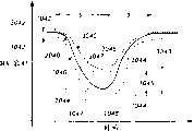
图1A-1H是在收缩和舒张期间健康的人心脏、不健康的人心脏和DMVA辅助的心脏的左、右心室所排出血液的与时间相关的压力和体积关系的图示;1A-1H are graphical representations of the time-dependent pressure and volume relationship of blood expelled by the left and right ventricles of a healthy human heart, an unhealthy human heart, and a DMVA-assisted heart during systole and diastole;
图1I-1J分别是在收缩和舒张期间健康的人心脏和DMVA辅助的心脏的左、右心室内的与时间相关的血压的图示;1I-1J are graphical representations of time-dependent blood pressure in the left and right ventricles of a healthy human heart and a DMVA-assisted heart during systole and diastole, respectively;
图1K-1L是在收缩期间健康的人心脏和DMVA辅助的心脏的从左、右心室中排出的与时间相关的血液流率的图示;Figures 1K-1L are graphical representations of time-dependent blood flow rates expelled from the left and right ventricles of a healthy human heart and a DMVA-assisted heart during systole;
图1M是在两个DMVA辅助的完整心脏循环的顺序中发生的进出于心脏心室的与时间相关的血液流率的图示;Figure 1M is a graphical representation of the time-dependent blood flow rate into and out of the ventricle of the heart that occurs in the sequence of two DMVA-assisted complete cardiac cycles;
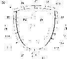
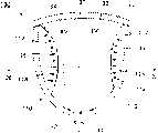
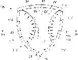
图2A-2I是显示了本发明的心脏用DMVA装置的动作顺序的剖视图,该装置可如图1A-1M示出地那样来辅助收缩和舒张的功能;2A-2I are cross-sectional views showing the action sequence of the heart DMVA device of the present invention, which can assist the systolic and diastolic functions as shown in FIGS. 1A-1M;
图2J-2O是显示了DMVA装置的非所需的操作和/或效果的示意性剖视图,其缺乏根据本发明提供的正确控制和/或结构特征;2J-2O are schematic cross-sectional views showing undesired operation and/or effects of a DMVA device, which lack proper control and/or structural features provided in accordance with the present invention;
图2P-2R是显示了DMVA装置对患有肺高血压和右心室肥大的心脏的操作和/或效果的示意性剖视图;2P-2R are schematic cross-sectional views showing the operation and/or effect of the DMVA device on a heart with pulmonary hypertension and right ventricular hypertrophy;
图2S-2U是显示了DMVA装置对患有扩张性心肌病的心脏的操作和/或效果的示意性剖视图;2S-2U are schematic cross-sectional views showing the operation and/or effect of the DMVA device on a heart with dilated cardiomyopathy;
图3A和3B是显示了现有技术DMVA装置的衬垫在心脏壁上的动作的示意性剖视图;3A and 3B are schematic cross-sectional views showing the action of the liner of the prior art DMVA device on the heart wall;
图4A、4B和4C是显示了本发明的一种优选DMVA杯形件的衬垫在心脏壁上的动作的示意性剖视图;Figures 4A, 4B and 4C are schematic cross-sectional views showing the action of a liner of a preferred DMVA cup of the present invention on the heart wall;
图5A是用于使用传感器数据来引导DMVA安装并评估DMVA影响下的心脏性能的一般方法的流程图;5A is a flowchart of a general method for using sensor data to guide DMVA installation and assess cardiac performance under the influence of DMVA;
图5B是用于自动调节DMVA杯形件一个实施例的功能的一种更具体算法的流程图;Figure 5B is a flowchart of a more specific algorithm for automatically adjusting the function of one embodiment of the DMVA cup;
图6A、6B和6C是收缩促动中的安装在DMVA杯形件内的传感器的示意性图示;6A, 6B and 6C are schematic illustrations of a sensor mounted within a DMVA cup during contraction actuation;
图7是舒张促动中的安装在DMVA杯形件内的传感器的示意性图示;Figure 7 is a schematic illustration of a sensor mounted within a DMVA cup during diastolic actuation;
图8是带有嵌入在其中的MRI线圈的DMVA杯形件的示意性图示;Figure 8 is a schematic illustration of a DMVA cup with an MRI coil embedded therein;
图9A和9B是外部X射线成像过程的示意性图示,其用于收集病人的数据和安装在病人体内的DMVA杯形件的数据;Figures 9A and 9B are schematic illustrations of an external X-ray imaging process used to collect data on a patient and a DMVA cup installed in the patient;
图10A是处于心脏的收缩压缩期间的集成在DMVA装置中的电生理性传感器和/或电极的示意性图示;Figure 10A is a schematic illustration of electrophysiological sensors and/or electrodes integrated in a DMVA device during systolic compression of the heart;
图10B是图10A所示DMVA装置的电生理性传感器和衬垫的示意性图示;Figure 10B is a schematic illustration of the electrophysiological sensors and pads of the DMVA device shown in Figure 10A;
图11是集成在杯形件和驱动组件中的工作流体压力和/或流率传感器的示意性图示;Figure 11 is a schematic illustration of a working fluid pressure and/or flow rate sensor integrated in the cup and drive assembly;
图12是集成在杯形件和驱动组件中的工作流体压力传感器的一个备选实施例的示意性图示;Figure 12 is a schematic illustration of an alternative embodiment of a working fluid pressure sensor integrated in the cup and drive assembly;
图13是位置检测机构的若干实施例的示意性图示,其用于检测DMVA装置的衬垫在操作期间的位置;13 is a schematic illustration of several embodiments of a position detection mechanism for detecting the position of a pad of a DMVA device during operation;
图14是DMVA杯形件的示意性图示,其中在关键的杯形件部件上涂覆了造影剂;Figure 14 is a schematic illustration of a DMVA cup with contrast agent coated on key cup components;
图15是用于操作和控制DMVA装置的带有性能反馈的整体控制系统的示意图;Figure 15 is a schematic diagram of an overall control system with performance feedback for operating and controlling a DMVA device;
图16A是本发明DMVA装置的另一实施例的示意性图示,包括带有卷式膜片的整体式密封件和衬垫;Figure 16A is a schematic illustration of another embodiment of a DMVA device of the present invention comprising an integral seal and gasket with a rolled membrane;
图16B是图16A所示DMVA装置的卷式膜片和杯形件壳体之间的粘合的一个实施例的详细视图;Figure 16B is a detailed view of one embodiment of the bond between the rolled membrane and the cup housing of the DMVA device shown in Figure 16A;
图17A-17H是DMVA装置的平坦式和卷式膜片衬垫的备选实施例的详细视图,尤其显示了这种平坦式和卷式膜片衬垫与杯形件壳体之间的粘合;17A-17H are detailed views of alternative embodiments of the flat and rolled diaphragm liners of the DMVA device, particularly showing the adhesion between such flat and rolled diaphragm liners and the cup housing. combine;
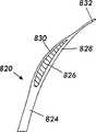
图18A-18C是若干DMVA杯形件的密封件的备选实施例的详细视图,其中显示了自由形状、初始安装形状、部分复原形状和最终位置;18A-18C are detailed views of alternative embodiments of seals for several DMVA cups showing the free shape, initial installed shape, partially recovered shape, and final position;
图19A是主动式密封件的详细剖视图,DMVA装置可通过它而与心脏更牢固地接合;Figure 19A is a detailed cross-sectional view of an active seal by which a DMVA device can be more securely engaged with the heart;
图19B和19C是图19A所示的主动式密封件的被动状态和主动状态的详细剖视图;19B and 19C are detailed cross-sectional views of the passive and active states of the active seal shown in FIG. 19A;
图20类似于图19A-19C所示密封件的主动式密封件的剖视图,其还包括主动式释放机构,当DMVA装置安装到心脏上时其被促动;20 is a cross-sectional view of an active seal similar to the seal shown in FIGS. 19A-19C , further comprising an active release mechanism that is actuated when the DMVA device is mounted on the heart;
图21A是被动式密封件的剖视图,其包括有在DMVA装置安装到心脏上时被展开的释放机构,其中显示了接合和密封之前的状态;21A is a cross-sectional view of a passive seal including a release mechanism deployed when the DMVA device is installed on the heart, showing the state prior to engagement and sealing;
图21B是图21A所示被动式密封件的剖视图,其显示为处于自由的和接合/密封的状态;Figure 21B is a cross-sectional view of the passive seal shown in Figure 21A, shown in a free and engaged/sealed state;
图22A是DMVA装置的衬垫和密封件的一个实施例的剖视图,包括局部特殊化的材料和/或表面纹理;22A is a cross-sectional view of one embodiment of a gasket and seal for a DMVA device, including locally specialized materials and/or surface textures;
图22B是图22A所示DMVA装置的一个衬垫的详细剖视图;Figure 22B is a detailed cross-sectional view of one liner of the DMVA device shown in Figure 22A;
图23A是DMVA装置的另一实施例的剖视图,它还包括用于与连接在心脏上的密封件脱开的机构;Figure 23A is a cross-sectional view of another embodiment of a DMVA device, which also includes a mechanism for disengaging a seal attached to the heart;
图23B和23C是图23A所示DMVA装置的可拆式密封件的实施例的详细剖视图;23B and 23C are detailed cross-sectional views of embodiments of the removable seal of the DMVA device shown in FIG. 23A;
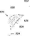
图24是DMVA杯形件的一个实施例的详细侧剖视图,其形成有中空的壁结构,包括设于水平面中的交错的结构肋和空腔;Figure 24 is a detailed side cross-sectional view of one embodiment of a DMVA cup formed with a hollow wall structure comprising alternating structural ribs and cavities disposed in the horizontal plane;
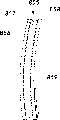
图25A是DMVA杯形件的另一实施例的详细顶剖视图,其形成有中空的壁结构,包括设于纵向平面中的交错的结构肋和空腔;25A is a detailed top cross-sectional view of another embodiment of a DMVA cup formed with a hollow wall structure comprising alternating structural ribs and cavities disposed in a longitudinal plane;
图25B是图25A的DMVA装置的肋和外壳之间的结构接头的详细顶剖视图;25B is a detailed top cross-sectional view of the structural joint between the ribs and the housing of the DMVA device of FIG. 25A;
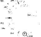
图26是用于操作和控制DMVA装置的带有性能反馈的整体控制系统的示意图;Figure 26 is a schematic diagram of an overall control system with performance feedback for operating and controlling a DMVA device;
图27是DMVA控制系统的示意图,包括算法、输入数据和输出数据之间的关系,该控制系统用于在实践或心脏再生中操作和控制DMVA装置;Figure 27 is a schematic diagram of a DMVA control system, including the relationship between algorithms, input data, and output data, for operating and controlling the DMVA device in practice or cardiac regeneration;
图28是DMVA装置的另一实施例的剖视图,它还包括可植入的往复式泵,用来驱动DMVA杯形件和其中的心脏的收缩和舒张促动;和28 is a cross-sectional view of another embodiment of a DMVA device, which also includes an implantable reciprocating pump for driving systolic and diastolic actuation of the DMVA cup and the heart therein; and
图29是DMVA装置的另一实施例的剖视图,它还包括可植入的相变泵,用来驱动DMVA杯形件和其中的心脏的收缩和舒张促动。29 is a cross-sectional view of another embodiment of a DMVA device, further comprising an implantable phase change pump for driving systolic and diastolic actuation of the DMVA cup and the heart therein.
本发明将结合优选实施例来进行介绍,然而应当理解,这并不意图将本发明限于所述的实施例。相反,其意图是覆盖所有包括在由所附权利要求限定的本发明精神和范围内的替代、改进和等同物。The invention will be described in conjunction with the preferred embodiments, however it should be understood that it is not intended to limit the invention to the described embodiments. On the contrary, the intention is to cover all alternatives, modifications and equivalents as included within the spirit and scope of the invention as defined by the appended claims.
实施本发明的最佳方式Best Mode for Carrying Out the Invention
为了总体上理解本发明,应当参阅附图。在图中采用相似的标号来表示相同的部件。For a general understanding of the invention, reference should be made to the accompanying drawings. Like reference numerals are used in the figures to designate like parts.
在介绍本发明时,在描述中使用了多种术语。在心脏领域中广泛使用标准术语。例如可参阅Bronzino,J.D.,生物医学工程手册,第二版,卷I,CRC出版社,2000年,第3-14和418-458页;或者基础心脏学,Clive Rosendorf M.D.编辑,W.B.Saunders公司,2001年,第23-699页,这些公开内容通过引用结合于本文中。In describing the present invention, a variety of terms are used in the description. Standard terminology is widely used in the cardiac field. See for example Bronzino, J.D., Handbook of Biomedical Engineering, Second Edition, Vol. I, CRC Press, 2000, pp. 3-14 and 418-458; or Basic Cardiology, edited by Clive Rosendorf M.D., W.B. Saunders Co., 2001, pp. 23-699, the disclosures of which are incorporated herein by reference.
如在这里使用的那样,术语“杯形件”意指本发明的直接机械式心室辅助装置,这种装置包括杯形外壳。术语“杯形件”、“DMVA杯形件”、“DMVA装置”和“DMVA设备”在本说明书中可互换地使用,并用来指本发明的其各种实施例中的整个直接机械式心室辅助装置,除非另有详细的指明。As used herein, the term "cup" means a direct mechanical ventricular assist device of the present invention that includes a cup-shaped housing. The terms "cup", "DMVA cup", "DMVA device" and "DMVA device" are used interchangeably in this specification and are used to refer to the entire direct mechanical Ventricular assist devices, unless otherwise specified in detail.
如在这里使用的那样,缩略语LV意指术语“左心室”或“左心室的”,术语RV意指术语“右心室”或“右心室的”,其适用于具体的上下文。As used herein, the abbreviation LV means the term "left ventricle" or "left ventricle" and the term RV means the term "right ventricle" or "right ventricle", as appropriate to the specific context.
针对心脏的心室所使用的“右”和“左”相对于病人身体的右和左并依照医疗实践而定,其中左心室将血液经由主动脉瓣排到主动脉中,而右心室将血液经由肺动脉瓣排到肺动脉中。然而,显示了本发明和包含在其中的心脏的实际应用的图是沿着面向病人身体的方向看去的。因此在这些图中,左心室在所有这类图中处于右侧,反之亦然,这与观看X光照片和医学领域的相关器官图时的情形相同。出于使这些图清晰的目的,左、右心室分别标为“LV”和“RV”。The terms "right" and "left" for the ventricles of the heart are relative to the right and left of the patient's body and are dictated by medical practice, where the left ventricle drains blood into the aorta via the aortic valve and the right ventricle drains blood via the aortic valve into the aorta The pulmonary valve drains into the pulmonary artery. However, the diagrams showing the invention and the heart incorporated therein in practice are viewed in a direction facing the patient's body. So in these figures the left ventricle is on the right side in all such figures and vice versa, as is the case when looking at x-ray pictures and related organ maps in the medical field. For purposes of clarity in these figures, the left and right ventricles are labeled "LV" and "RV", respectively.
如在这里使用的那样,术语“正常心脏”和“健康的心脏”可互换地使用,意指正常的未患病的人心脏,其不需要DMVA辅助或其它医疗护理。As used herein, the terms "normal heart" and "healthy heart" are used interchangeably to mean a normal, non-diseased human heart that does not require DMVA assistance or other medical attention.
如在这里使用的那样,术语“心脏功能”意指心脏的功能,例如系统循环和肺循环中的血液泵送;以及其它功能,例如在创伤性事件如心肌梗塞之后的心脏康复和再生。表示这些功能的参数是物理参数,包括但不限于血压、血液流率、血量等;以及化学和生物学参数,例如氧气、二氧化碳、乳酸的浓度等。As used herein, the term "cardiac function" means the functions of the heart, such as blood pumping in the systemic and pulmonary circulation; and other functions, such as cardiac rehabilitation and regeneration following a traumatic event such as myocardial infarction. Parameters indicative of these functions are physical parameters including, but not limited to, blood pressure, blood flow rate, blood volume, etc.; and chemical and biological parameters, such as oxygen, carbon dioxide, lactate concentration, and the like.
如在这里使用的那样,术语“心脏状况”意指包括与心脏功能有关的参数,以及任何其它的参数,包括但不限于尺寸、形状、外观、位置等。As used herein, the term "heart condition" is meant to include parameters related to heart function, as well as any other parameters including, but not limited to, size, shape, appearance, location, and the like.
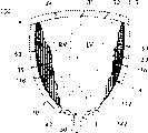
对于DMVA的有效操作而言,特别重要的是连续监测左、右心室的几何形状的变化(例如RV和LV的收缩末期容量和舒张末期容量以及尺寸特性);2)心室动态特性(例如在整个DMVA循环期间心室尺寸、流速、所计算的压力梯度和壁运动的动态变化);3)心室的相互作用(前述项1和2彼此作用的相关影响);4)装置/心脏的相互作用(例如在整个促动循环中装置的促动膜片和心外膜面之间的关系,以及例如对心室壁轮廓的形态变化、RV突出的影响)。Of particular importance for effective operation of the DMVA is continuous monitoring of changes in left and right ventricular geometry (e.g., RV and LV end-systolic and end-diastolic volumes and dimensional properties); 2) ventricular dynamics (e.g., Dynamic changes in ventricular size, flow velocity, calculated pressure gradient, and wall motion during the DMVA cycle); 3) ventricular interactions (relevant effects of
因此,在图6A-7中所示并且在本说明书的下文中将介绍的本发明的一个实施例中,在DMVA心脏杯形件中集成有至少一个超声波探针,其用于连续地监测左、右心室以及相关的装置-心外膜的相互作用,后者控制了整个DMVA促动循环期间RV和LV的这些形态变化、动态特性、容积变化和流速。左、右心室压缩的这种可视检测分析允许采用控制算法以连续的方式调节控制参数,从而实现最佳的轮廓以达到最佳的左、右心室支撑。对于与采用DMVA来支撑心脏的特有挑战性相关的多种因素而言,该监测是很重要的。Thus, in one embodiment of the invention shown in Figures 6A-7 and described later in this specification, at least one ultrasound probe is integrated in the DMVA cardiac cup for continuously monitoring the left , the right ventricle, and associated device-epicardial interactions that control these morphological changes, dynamic properties, volume changes, and flow rates of the RV and LV throughout the DMVA-actuated cycle. This visual detection analysis of left and right ventricular compression allows the control algorithm to adjust control parameters in a continuous manner to achieve optimal contouring for optimal left and right ventricular support. This monitoring is important for a number of factors related to the unique challenges of using DMVA to support the heart.
存在有多种控制算法,其中可以能够实现最佳心脏促动的方式来执行DMVA驱动控制。例如,在DMVA支撑期间产生的肺血管和系统血管阻力和流速的正在进行的变化部分地由左、右心室对外部促动力的响应来支配。可以响应于这些测得变量来调节来自驱动的力输送,以便实现更有利的血液动力学特性,并保证力输送足以克服肺和系统的血管床和瓣膜结构的固有阻力特性。需要调节收缩和舒张促动力,以便实现最佳的双心室效果。可以调节这些力(压力/时间的变化和/或容积/时间的变化),以便在收缩和舒张促动阶段中实现增大的部分。在下面的段落中将解释这种驱动动态优化的一些通用例子。There are various control algorithms in which DMVA drive control can be performed in such a way that optimal cardiac actuation can be achieved. For example, the ongoing changes in pulmonary and systemic vascular resistance and flow that occur during DMVA support are governed in part by the response of the left and right ventricles to external actuation forces. Force delivery from the drive can be adjusted in response to these measured variables in order to achieve more favorable hemodynamic properties and to ensure that force delivery is sufficient to overcome the inherent resistive properties of the vascular bed and valve structures of the lung and system. Systolic and diastolic actuation forces need to be modulated in order to achieve optimal biventricular effect. These forces (change in pressure/time and/or change in volume/time) can be adjusted to achieve increased fractions during the systolic and diastolic actuation phases. Some general examples of such driven dynamic optimization are explained in the following paragraphs.
收缩促动的前面部分主要集中在右心室的动态特性上。可对右心室进行观察表明,早期收缩的压力相对柔和,并且允许右心室有最大的压缩。右心室的压缩必须集中在避免和/或减少因急剧的早期收缩压缩而引起的右心室突出的程度。这种可在装置的基部(上边缘)处观察到的RV突出主要会允许血液积聚在右心室游离壁的隆起到装置之外的那一部分上。血液的这种突出与肺部血流的等量减少和整体下降的心脏输出有关,这是因为这些流动减少与下降的左心室充盈呈镜像关系。The preceding part of systolic actuation focused on the dynamic properties of the right ventricle. Observation of the right ventricle shows that early systolic pressures are relatively gentle and allow maximal compression of the right ventricle. Compression of the RV must be focused on avoiding and/or reducing the extent of RV protrusion caused by acute early systolic compression. This RV protrusion observable at the base (upper edge) of the device would primarily allow blood to pool on the portion of the right ventricular free wall that protrudes beyond the device. This prominence of blood is associated with an equivalent reduction in pulmonary blood flow and an overall decreased cardiac output, since these reductions in flow are in a mirror image relationship to decreased left ventricular filling.
收缩促动循环的后半部分集中在最大的左心室压缩上,同时避免过度的左心室压缩。左心室压缩的一些关键特性包括实现那种程度的左心室压缩,这导致心室的最大射血,但不允许心脏的心脏内(内部)表面彼此接触。如果LV未被足够地压缩,血液将聚集在肺部并且会导致肺水肿。The second half of the systolic-actuation cycle focuses on maximal LV compression while avoiding excessive LV compression. Some key properties of left ventricular compression include achieving that degree of left ventricular compression, which results in maximal ejection of blood from the ventricle, but does not allow the endocardial (inner) surfaces of the heart to contact each other. If the LV is not compressed enough, blood will pool in the lungs and pulmonary edema will result.
可以改变收缩压力的绝对大小和收缩压缩的定时(timing),以便使左心室的排空特性最大。根据这些原理,左心室顺流最大(可通过压缩期间的左心室容积存在最大的减少而看出),同时可以避免与内心室相接触有关的创伤。换句话说,通过最佳的LV压缩(收缩促动),在心脏内表面之间总是存在有流体介质。过大的力会导致左心室血液的过度排代,使得内表面会彼此接触和彼此碰伤。类似地,早期压缩期间的过大力会导致右心室游离壁和右心室内的隔膜之间产生突出和摩擦。The absolute magnitude of systolic pressure and the timing of systolic compression can be varied to maximize the emptying properties of the left ventricle. According to these principles, forward flow of the left ventricle is maximized (as seen by the greatest reduction in left ventricular volume during compression), while trauma associated with inner ventricle contact is avoided. In other words, with optimal LV compression (systolic actuation), there is always a fluid medium between the inner surfaces of the heart. Excessive force can cause excessive displacement of left ventricular blood, causing the inner surfaces to touch and bruise each other. Similarly, excessive force during early compression can cause protrusion and friction between the RV free wall and the septum within the RV.
类似地,可监测左、右心室的动态特性以保证最佳的舒张促动。最佳DMVA辅助的基本原理实现了左、右心室的舒张促动,同时实现了最大的舒张容积。这可通过增加-dP/dt(压力变化/时间变化)和/或dV/dt(容积变化/时间变化)来实现,以便实现最佳的舒张促动,其可增强舒张的充盈率,克服DCC或任何压缩方法所固有的负面(限制性)影响。这种舒张促动可调节到能够实现最大的-dP/dt而不会允许在促动膜片和心脏心外膜面之间产生分离的位置点。Similarly, dynamic properties of the left and right ventricles can be monitored to ensure optimal diastolic actuation. The rationale for optimal DMVA assistance achieves diastolic actuation of the left and right ventricles while maximizing the diastolic volume. This can be achieved by increasing -dP/dt (change in pressure/change in time) and/or dV/dt (change in volume/change in time) in order to achieve optimal diastolic actuation, which enhances diastolic filling and overcomes DCC Or the negative (restrictive) effects inherent in any compression method. This diastolic actuation is adjustable to a point where a maximum -dP/dt is achieved without allowing separation between the actuating membrane and the epicardial surface of the heart.
促动膜片与心脏的心外膜面的任何分离表示,在促动循环的该阶段期间所施加的负作用力太急剧,需要以更缓和的方式来输送。在舒张促动期间衬垫与心脏的分离基本上将促动力从心外膜上移开,导致心脏被动地生长和/或以无辅助的方式生存。下面将在本说明书中更详细地说明本发明DMVA装置的实施例的细节,其包括用于检测左、右心室和驱动机构中的相关变化/驱动控制算法的机构。Any separation of the actuation membrane from the epicardial surface of the heart indicates that the negative force applied during this phase of the actuation cycle was too sharp and needs to be delivered in a more gradual manner. Separation of the liner from the heart during diastolic actuation essentially removes the actuation force from the epicardium, causing the heart to grow passively and/or survive in an unassisted manner. Details of an embodiment of the DMVA device of the present invention including mechanisms for detecting relative changes in left and right ventricles and drive mechanisms/drive control algorithms are described in greater detail in this specification below.
下面还将在本说明书中限定优选的材料特性。然而,全面特性将在以下段落中提供。衬垫的最佳特性最好应描述为具有“各向同性”。换句话说,衬垫材料作用在心室肌肉上,其方式允许心室肌肉改变其形态形状,从而最佳地顺应于心脏的自然趋向。这样,在施加这种外部力时,材料不会使心脏“变形”到由肌肉的改变形态的自然趋向所规定的范围以外。Preferred material properties are also defined in the description below. However, full characterization will be provided in the following paragraphs. The optimal properties of the liner are best described as being "isotropic". In other words, the cushion material acts on the ventricular muscle in a way that allows the ventricular muscle to change its morphological shape to optimally follow the heart's natural tendencies. In this way, upon application of such an external force, the material does not "deform" the heart beyond that dictated by the natural tendency of the muscle to change shape.
然而,这并不是说心脏以能够恢复到其正常搏动状态的方式而被压缩。相反,源于DMVA促动的收缩和舒张的形态变化与原本正常功能心脏的收缩和膨胀期间所预计的显然有一些程度的不同。然而,重要的是衬垫和杯形壳体的材料允许心肌承受这种机械式诱发的形态变化,其方式允许肌肉基于其物理特性和趋向而变形。稍差一些的材料会导致更有可能发生的创伤,并且具有以会改变心脏的“自然”趋向和这类材料特性的方式而折叠和变形的自身趋向,从而导致心肌受损。However, this is not to say that the heart is compressed in such a way that it can return to its normal beating state. In contrast, the morphological changes resulting from DMVA-induced systole and diastole apparently differ to some extent from what would otherwise be expected during systole and dilation of a normally functioning heart. However, it is important that the material of the liner and cup shell allow the myocardium to withstand this mechanically induced morphological change in a manner that allows the muscle to deform based on its physical properties and tendencies. Lesser materials lead to more likely trauma and have a natural tendency to fold and deform in a way that alters the "natural" tendency of the heart and the properties of such materials, resulting in damage to the heart muscle.
装置外壳的顺应性特性允许其响应于施加在心脏上的促动力以及心脏尺寸和/或形状的变化而恒定地改变形状。这一特征有利于减少心室创伤,因外壳可以变形而能够通过较小的切口进行安装而使得安装容易,并且有利于能够恒定地响应于心脏的变化形状的重要动态形态变化。装置的外壳由柔性材料构成,其具有适当顺应性和弹性,允许其可吸收收缩和舒张的促动力,使得能够一定地缓冲衬垫作用在心脏上的效果(例如,可以减缓驱动流体压力的急剧下降,使得可以避免在心脏中产生气穴和脱开,并且在收缩期间,可以减缓驱动流体压力的急剧增加,使得避免碰伤心脏)。外壳的这一独特品质减轻了在循环的任意时刻有过大的力施加在心脏上。壳体在整个压缩和松弛循环中顺应于左、右心室的动态变化,并且顺应于与心脏尺寸随时间变化相关的正在进行的整体变化,这是由于连续的机械式促动和相关的“重新塑造”效应作用于心脏上所导致的。The conformable properties of the device housing allow it to constantly change shape in response to actuation forces applied to the heart and changes in the size and/or shape of the heart. This feature facilitates reduced ventricular trauma, facilitates installation as the shell can be deformed to allow installation through smaller incisions, and facilitates important dynamic morphological changes in constant response to the changing shape of the heart. The outer shell of the device is constructed of a flexible material that is suitably compliant and elastic, allowing it to absorb systolic and diastolic actuation forces, enabling some cushioning of the effect of the liner on the heart (e.g., can moderate actuation fluid pressure surges). drop, so that cavitation and disengagement in the heart can be avoided, and during systole, the sharp increase in driving fluid pressure can be slowed down, so that bruising the heart is avoided). This unique quality of the shell alleviates excessive forces exerted on the heart at any point in the cycle. The shell conforms to the dynamics of the left and right ventricles throughout the cycle of compression and relaxation, and to the ongoing global changes associated with changes in heart size over time due to continuous mechanical actuation and associated "re- caused by the "shaping" effect acting on the heart.
本发明的与传感器和控制有关的方面Aspects of the invention relating to sensors and controls
本发明还包括利用传感器和传感器数据来(1)帮助安装DMVA装置以及(2)评估在DMVA影响下的心脏性能的方法。这样得到的传感器数据可帮助实时确认装置是否已经正确地安装,以及已经正确地操作和实现所需的心脏性能。检测数据还允许实时地调节杯形件的操作参数,以便对病人心血管系统的变化的生理状态作出响应。本发明包括至少十项与传感器和控制有关的方面,它们均描述如下:The present invention also includes methods of utilizing sensors and sensor data to (1) aid in the installation of DMVA devices and (2) assess cardiac performance under the influence of DMVA. The resulting sensor data can help confirm in real time that the device has been installed correctly, is operating correctly and achieving desired cardiac performance. The sensed data also allows for real-time adjustment of operating parameters of the cup in response to changing physiological states of the patient's cardiovascular system. The present invention includes at least ten aspects related to sensors and controls, all of which are described as follows:
1.用于结合心脏辅助装置(并不仅限于DMVA或DMVA杯形件)来使用传感器数据以执行这种功能如引导装置安装,并且优化装置的性能并引导其它心脏装置和系统的放置和操作的方法。1. For use of sensor data in conjunction with cardiac assist devices (and not limited to DMVA or DMVA cups) to perform such functions as guiding device installation, and optimizing device performance and guiding placement and operation of other cardiac devices and systems method.
2.适于检测(传感器数据)的特定心脏性能测量。2. Specific cardiac performance measurements suitable for detection (sensor data).
3.特定装置反馈控制参数。3. Specific device feedback control parameters.
4.特定反馈控制方法和算法。4. Specific feedback control methods and algorithms.
5.特定传感器类型和传感器位置。5. Specific sensor type and sensor location.
6.使用造影剂来增强传感器的灵敏度和专用性。6. Use of contrast agents to enhance sensor sensitivity and specificity.
7.传感器接口。7. Sensor interface.
8.用户接口。8. User interface.
9.传感器数据记录和分析能力。9. Sensor data recording and analysis capabilities.
10.适于检测(传感器数据)的特定装置性能测量。10. Specific device performance measurements suitable for detection (sensor data).
下面将在本说明书中简要介绍本发明的这些方面,然后参考附图进行更详细的介绍。These aspects of the invention are briefly described below in the present specification and then described in more detail with reference to the accompanying drawings.
本发明的方面1:下面将简要介绍结合心脏辅助装置使用传感器数据的方法,然后参考图5A进行更详细的介绍。这一方面涉及使用传感器数据来引导DMVA装置的安装并且评估在DMVA影响下的心脏性能的方法。该方法包括下述步骤,在这里它们以说明性而非限制性的方式来提供:
步骤1:建立病人的基础性能。Step 1: Establish the patient's baseline performance.
步骤2:建立所需的性能提高目标。Step 2: Establish desired performance improvement goals.
步骤3:预检查DMVA装置以验证关键的性能方面(可选)Step 3: Pre-inspect DMVA installations to verify key performance aspects (optional)
步骤4:将DMVA装置外科式安装在病人中。Step 4: The DMVA device is surgically installed in the patient.
步骤5:使用源自步骤1和2的预定设置来促动DMVA装置。Step 5: Actuate the DMVA device using the predetermined settings from
步骤6:操作DMVA装置和收集传感器数据。也见于本发明的方面#5(特定传感器类型和传感器位置)Step 6: Operate the DMVA device and collect sensor data. See also aspect #5 of the invention (specific sensor types and sensor locations)
步骤7:分析传感器数据。也见于本发明的方面#2(传感器数据)、方面#9(传感器数据记录和分析能力)以及用于特定数据和数据分析方法的方面#10(适于检测的特定装置性能测量)。Step 7: Analyze sensor data. See also Aspect #2 (Sensor Data), Aspect #9 (Sensor Data Recording and Analysis Capabilities) and Aspect #10 (Specific Device Performance Measurements Suitable for Detection) of the invention for specific data and data analysis methods.
步骤8:调节DMVA控制参数。Step 8: Adjust DMVA control parameters.
步骤9:重复步骤6-7,直到实现了所需的心脏性能。Step 9: Repeat steps 6-7 until the desired cardiac performance is achieved.
步骤10:程序数据记录-输送(可选)Step 10: Program Data Recording - Transport (Optional)
步骤11:准备病人康复。Step 11: Prepare the patient for recovery.
步骤12:监测病人的心脏性能Step 12: Monitor the Patient's Cardiac Performance
本发明的方面2:传感器数据。在本发明方面1的上述方法的步骤6中收集的传感器数据优选非限制性地包括下面列出类型的数据。下面将结合图6A-14来详细地介绍特定的传感器类型和传感器位置(也见于本发明的方面5)。
1.解剖学数据,例如,由所植入的加速计检测到的心脏壁的运动;由所植入的超声换能器/传感器装置检测到的杯形件与心脏的配合;和/或由可测量DMVA装置的工作流体容积的传感器所推断出来的心脏心室的血量排量。另外,DMVA装置包括传感器数据,例如来自超声换能器/传感器的数据,其可被分析和编辑以产生心脏和杯形件的图像。这种图像数据在实际中是很有用的,因为它为医师提供了所需的信息,用于检验杯形件与心脏的正确配合并检验是否实现了正确的收缩和舒张促动,其包括但不限于心室壁和隔膜几何形状、RV/LV关系和心外膜-衬垫关系中的动态变化。1. Anatomical data, e.g., motion of the heart wall detected by an implanted accelerometer; fit of the cup to the heart detected by an implanted ultrasound transducer/sensor device; and/or The blood volume displacement of the ventricles of the heart is inferred from sensors that measure the working fluid volume of the DMVA device. In addition, the DMVA device includes sensor data, such as data from an ultrasound transducer/sensor, which can be analyzed and edited to generate images of the heart and cup. This image data is useful in practice because it provides the physician with the information needed to verify the correct fit of the cup to the heart and to verify that proper systolic and diastolic actuation is achieved, including but Not limited to dynamic changes in ventricular wall and septal geometry, RV/LV relationship, and epicardium-cushion relationship.
2.血液动力学数据,例如下述:a)血液流率,从DMVA装置的工作流体流率的计算中推断出来;b)右心室-左心室的相互作用;c)主动脉血压,例如通过常规得到的血压数据的归一化,和/或基于来自设在DMVA装置的工作流体中的与心肌接触的附近点处的压力传感器的数据的计算值,和/或来自工作流体的压力/容积数据,和/或主动脉瓣处的流量随时间的声学数据;d)肺部血压,例如通过常规得到的血压数据的归一化,和/或基于来自设在DMVA装置的工作流体中的与心肌接触的附近点处的压力传感器的数据的计算值,和/或来自工作流体的压力/容积数据,和/或主动脉瓣处的流量随时间的声学数据;e)RV和LV的每搏输出量;f)基于测得或算出压力梯度的经过所有四个心瓣膜的流速。2. Hemodynamic data, such as the following: a) blood flow rate, deduced from the calculation of the working fluid flow rate of the DMVA device; b) right ventricle-left ventricle interaction; c) aortic blood pressure, for example by Normalization of conventionally obtained blood pressure data, and/or calculations based on data from pressure transducers placed in the working fluid of the DMVA device at nearby points in contact with the myocardium, and/or pressure/volume from the working fluid data, and/or acoustic data of flow at the aortic valve over time; d) pulmonary blood pressure, for example by normalization of conventionally obtained blood pressure data, and/or based on the Calculation of data from pressure transducers at nearby points of myocardial contact, and/or pressure/volume data from working fluid, and/or acoustic data of flow at the aortic valve over time; e) RV and LV beat-per-stroke output; f) flow rate through all four heart valves based on measured or calculated pressure gradients.
3.功能性数据,例如心脏射血分数,其从基于上述解剖学和/或血液动力学数据的计算值中得到,和/或从基于设在超声换能器/传感器装置中的杯形件的直接超声图像的计算值中得到;以及RV-LV的配合和关系。3. Functional data, such as cardiac ejection fraction, derived from calculations based on the aforementioned anatomical and/or hemodynamic data, and/or from cups based on the ultrasonic transducer/sensor device and the RV-LV fit and relationship.
4.电生理性数据,例如,电压和电压随时间的变化,其由设于杯形件的内表面上且与心肌接触的电传感器得到;电压差异,其由设在心肌上的不同点处的这种传感器之间的比较而得到;随时间变化的电压差,其从这些多种传感器中得到;电流和电流随时间的变化,其从这些电传感器中得到。可以理解,在一些实施例中,DMVA杯形件可使心脏一定程度地电隔离,但这会使标准心电描记术更困难一些。然而,这种隔离也会使设于杯形件内的电生理监测和刺激装置更有效地操作;这是因为它们很容易受到尤其是来自外部源的电噪音的影响。因此,DMVA杯形件可集中在将电刺激能量输送给封闭在其中的组织上。为了有利地使用这种性能,DMVA杯形件还包括集成式电测量能力(例如心电图)和集成式电刺激能力(例如起搏和心脏复律-去纤颤),其中这种测量能力和这种刺激能力还集成在反馈控制回路中,通过它可以完全地控制和辅助杯形件内的心脏的自然压缩。在另一实施例中采用了顶端起搏的做法,其中电刺激信号在DMVA杯形件的顶端处施加在心脏上。在这种实施例中,顶端起搏器接地式地连在病人身上,使得施加到病人身上的电流不会产生电位差,从而增强了对病人的安全性。4. Electrophysiological data, such as voltage and voltage over time, obtained from electrical sensors placed on the inner surface of the cup and in contact with the myocardium; voltage differences, obtained from electrical sensors placed at different points on the myocardium from the comparison between such sensors of 100; the voltage difference over time, which is obtained from these various sensors; and the current and current variation over time, which are obtained from these electrical sensors. It will be appreciated that in some embodiments the DMVA cup may electrically isolate the heart to some degree, but this would make standard electrocardiography somewhat more difficult. However, this isolation also allows the electrophysiological monitoring and stimulation devices located within the cup to operate more efficiently; this is because they are susceptible to electrical noise, especially from external sources. Thus, the DMVA cup can focus on delivering electrical stimulation energy to the tissue enclosed within it. To use this capability to advantage, the DMVA cup also includes integrated electrical measurement capabilities (such as electrocardiogram) and integrated electrical stimulation capabilities (such as pacing and cardioversion-defibrillation), where this measurement capability and this This stimulation capability is also integrated in a feedback control loop by which the natural compression of the heart within the cup is fully controlled and assisted. In another embodiment, apical pacing is employed, wherein electrical stimulation signals are applied to the heart at the apex of the DMVA cup. In such an embodiment, the tip pacemaker is grounded to the patient so that the current applied to the patient does not create a potential difference, thereby enhancing patient safety.
5.生物化学/生物数据;例如下述例子:a)来自与心肌接触的光学氧气传感器的血液氧气;b)来自与心肌接触的光学葡萄糖传感器的血糖;c)来自光学摩尔渗透压浓度传感器的摩尔渗透压浓度;d)来自荧光探针传感器或近红外传感器的乳酸盐或乳酸或其它疲劳标示;e)来自与组织接触的光学药物传感器的药物摄入量;f)细胞信号、细胞应力和心室重塑的分子标示,包括但不限于细胞活素类、类激素、氮氧化物、游离氧基、热休克蛋白、金属蛋白和相关的分子基质。5. Biochemical/biological data; such as the following examples: a) blood oxygen from an optical oxygen sensor in contact with the myocardium; b) blood glucose from an optical glucose sensor in contact with the myocardium; c) blood oxygen from an optical osmolarity sensor Osmolarity; d) lactate or lactic acid or other markers of fatigue from fluorescent probe sensors or near-infrared sensors; e) drug uptake from optical drug sensors in contact with tissue; f) cell signaling, cell stress and molecular markers of ventricular remodeling, including but not limited to cytokines, hormones, nitrogen oxides, free oxygen, heat shock proteins, metalloproteins, and related molecular substrates.
6.声学数据,例如心脏和肺自然发出的声音。更具体地说,这种数据可包括下述:a)来自与心脏接触的可检测自然发出声音的麦克风的数据,例如那些由肌肉收缩、心脏瓣膜操作、心脏杂音/心律不齐、心室内或经过心脏瓣膜的血液层流或紊流所产生的声音;以及S1、S2、S3和S4、声音;b)来自与肺接触的麦克风的数据,该麦克风可检测例如收集用来监测呼吸率的呼吸声;c)来自于与为杯形件提供动力的工作流体接触的麦克风的数据,该麦克风可检测由泄漏、局部堵塞或抽筋所产生的声音;d)来自可检测组织对引入该组织中的声能的所作出响应的麦克风的数据,这些声能例如为超声能量或在所有这种位置中的麦克风处所测得的多普勒频率声能;e)来自可检测装置-心脏相互作用的声音指示的麦克风的数据,这些相互作用包括摩擦/擦拭动作、衬垫从心脏表面上分离以及衬垫-外壳的接触/分离。6. Acoustic data, such as the natural sounds of the heart and lungs. More specifically, such data may include the following: a) Data from a microphone in contact with the heart that detects naturally occurring sounds, such as those caused by muscle contractions, heart valve operation, heart murmurs/arrhythmias, intraventricular or Sounds produced by laminar or turbulent blood flow through the heart valves; and S1 , S2 , S3 , and S4 , sounds; b) data from a microphone in contact with the lungs that detects, for example, collects for monitoring Breathing sounds from respiration rate; c) data from a microphone in contact with the working fluid powering the cup that can detect sounds produced by leaks, partial blockages, or cramps; d) data from tissue that can detect incoming The data of the responding microphone of the acoustic energy in the tissue, such as ultrasonic energy or Doppler frequency acoustic energy measured at the microphone in all such positions; e) from the detectable means- Microphone data indicative of the sound of cardiac interactions including rubbing/wiping action, liner separation from the heart surface, and liner-shell contact/separation.
7.组织特性数据,例如下述:a)刚度,其源于与心肌表面上的多个点接触的应变计的数据;b)血管化程度,其源于与心肌接触的毛细血流光学传感器的数据;以及c)药物或其它治疗剂摄入量,其源于装置内传感器的数据。7. Tissue property data, such as the following: a) stiffness, derived from data from strain gauges in contact with multiple points on the surface of the myocardium; b) degree of vascularization, derived from capillary flow optical sensors in contact with the myocardium and c) drug or other therapeutic agent intake derived from data from sensors within the device.
8.温度数据,例如下述:a)心肌温度,其源于设置成与心肌接触的温度传感器的数据;b)驱动流体的温度,其源于设置成与驱动流体接触的温度传感器的数据;c)肺的温度,其源于设置在杯形件中的与肺接触部分内的温度传感器的数据;以及e)芯体(core)温度测量,其源于设置在DMVA杯形件的壳体壁外部上或流体驱动机构或其真空管上的温度传感器的数据。这种芯体温度数据在感染的早期检测以及在冷却DMVA驱动流体以提供心肌、大脑和/或芯体温度的冷却的情况下的情况下尤其有用。8. Temperature data, such as the following: a) myocardial temperature, derived from data from a temperature sensor placed in contact with the myocardium; b) temperature of the drive fluid, derived from data from a temperature sensor placed in contact with the drive fluid; c) lung temperature derived from data from a temperature sensor placed in the cup in contact with the lung; and e) core temperature measurement derived from the housing placed in the DMVA cup Data from temperature sensors on the outside of the wall or on the fluid drive mechanism or its vacuum tubes. Such core temperature data is especially useful in the early detection of infection and in the case of cooling DMVA driving fluids to provide cooling of the myocardium, brain and/or core temperature.
9.光学数据,例如来自光学传感器的数据,该光学传感器可检测a)由同时引入其它形式的能量例如机械能量如振动和/或超声波所产生的运动、光谱吸收变化和/或折射率变化;b)组织对不同波长和/或光波长组合的光学问诊的响应。9. Optical data, e.g. from optical sensors that can detect a) motion, changes in spectral absorption and/or changes in refractive index resulting from the simultaneous introduction of other forms of energy, such as mechanical energy such as vibration and/or ultrasound; b) Tissue response to optical interrogation of different wavelengths and/or combinations of light wavelengths.
10.机械方面的数据,例如关键杯形件特征的机械应变,例如衬垫和/或杯形件壳体的挠曲。10. Mechanical aspects such as mechanical strain on key cup features such as liner and/or cup shell deflection.
本发明的方面3:DMVA反馈控制参数。上述传感器数据可用来控制DMVA的操作和心脏性能。在本发明中,这些参数优选非限制地包括下述装置控制参数,它们将在下文中参考图15、26和27来更详细地介绍:
1.输送给杯形件衬垫或从中排出的流体的总体积。1. The total volume of fluid delivered to or removed from the cup liner.
2.输送给杯形件衬垫或从中排出的流体体积之差(如RV与LV的比较)。2. The difference in volume of fluid delivered to or removed from the cup liner (eg, RV versus LV).
3.流到杯形件衬垫中或从中排出的流体的流率。3. The flow rate of fluid into or out of the cup liner.
4.输送给杯形件衬垫或从中排出的流体的压力。4. The pressure of the fluid delivered to or expelled from the cup liner.
5.输送给杯形件或从中排出的流体相对于下述因素的定时,这些因素例如为心电节奏、呼吸循环以及RV和LV功能之间的同步;以及这种定时与输送给杯形件或从中排出的流体压力和流体体积的变化率之间的关系。5. Timing of fluid delivery to or removal from the cup relative to factors such as cardiac rhythm, respiratory cycle, and synchronization between RV and LV functions; and the relationship between such timing and delivery to the cup Or the relationship between the pressure of the fluid being expelled from it and the rate of change of the volume of the fluid.
6.输送给杯形件或从中排出的流体相对于下述因素的频率,这些因素例如为新陈代谢需求、呼吸率、血液氧合性和心率。6. Frequency of fluid delivery to or removal from the cup relative to factors such as metabolic demand, respiration rate, blood oxygenation and heart rate.
7.输送给杯形件或从中排出的流体相对于下述因素的温度,这些因素例如为心肌温度、体温、肺温和/或病人的临床数据。7. The temperature of the fluid delivered to or removed from the cup relative to factors such as myocardial temperature, body temperature, lung temperature and/or clinical data of the patient.
8.心脏的电起搏,例如通过装置在心脏上进行的动作和/或结合在杯形件中并设于心脏顶端处或其它位置处的起搏器所引起;所有这些都必须调节成能够最佳地适于心脏的状况。8. Electrical pacing of the heart, e.g. by action of a device on the heart and/or a pacemaker incorporated in a cup and positioned at the apex of the heart or elsewhere; all of which must be regulated to enable Optimally adapted to the condition of the heart.
9.其它心脏辅助装置如主动脉内气囊辅助装置的促动。9. Actuation of other cardiac assist devices such as intra-aortic balloon assist devices.
10.呼吸辅助装置如呼吸器的促动。10. Actuation of respiratory assistance devices such as respirators.
11.报警电路的促动,例如警告临床和/或技术人员:装置的功能不正常或产生了不能接受的病人响应。11. Actuation of an alarm circuit, eg to alert clinical and/or technical personnel that the device is not functioning properly or producing an unacceptable patient response.
12.收缩和舒张促动期间的RV游离壁、LV游离壁和隔膜的形态变化。12. Morphological changes of the RV free wall, LV free wall and septum during systolic and diastolic actuation.
13.衬垫-心脏的相互作用,包括衬垫的滑动和分离。13. Pad-heart interaction, including pad sliding and separation.
14.RV和LV的几何形状-容积的变化和相关空间变化以及相互之间的相关动作。14. RV and LV geometry-volume changes and related spatial changes and relative motion between each other.
15.衬垫和壳体之间的容积/几何形状变化。15. Volume/geometry change between liner and shell.
本发明的方面4:DMVA反馈控制方法和算法。可对本发明方面#2的上述传感器数据进行分析以便以多种方式来控制DMVA操作和心脏性能,其非限制性地包括下述装置控制方法和算法,其中一些将在下文中参考图15、26和27来更详细地介绍。
1.验证DMVA装置是否正确安装的程序。该方法和算法非限制性地包括下述能力:a)验证杯形件正确地密封且定位在心脏上;b)验证杯形件在心脏上有足够的密封;c)验证没有过大体积的流体流经杯形件衬垫和心肌之间;d)验证心脏的正确收缩和舒张运动,包括左、右心室和RV-LV相互作用;e)验证装置中不存在泄漏;f)验证肺中不存在泄漏;g)验证心脏的正常流出特性;和/或h)保持恒定的胸腔容积,以帮助减少心理方面的问题。1. A procedure to verify that the DMVA unit is installed correctly. The method and algorithm include, without limitation, the ability to: a) verify that the cup is properly sealed and positioned on the heart; b) verify that the cup has an adequate seal on the heart; c) verify that there is no excessive volume Fluid flows between the cup liner and the myocardium; d) verification of correct systolic and diastolic motion of the heart, including left and right ventricle and RV-LV interaction; e) verification of the absence of leaks in the device; f) verification of There are no leaks; g) verifying the normal outflow properties of the heart; and/or h) maintaining a constant chest volume to help reduce psychological concerns.
2.实现有效的RV和LV促动的方法和算法,包括RV和LV几何形状/容积变化。该方法和算法非限制性地包括精确地控制在心脏输出的整个范围上的心室压力-容积关系以及LV和RV游离壁、隔膜及心室的形态变化的能力。在本说明书的下文中将尤其参考图1A-1M、2A-2I和5B来提供该方法和算法的实施例的详细描述。2. Methods and algorithms to achieve efficient RV and LV actuation, including RV and LV geometry/volume changes. The methods and algorithms include, without limitation, the ability to precisely control the ventricular pressure-volume relationship over the full range of cardiac output and the morphological changes of the LV and RV free walls, septum and ventricles. A detailed description of embodiments of this method and algorithm will be provided later in this specification with particular reference to FIGS. 1A-1M , 2A-2I and 5B.
3.用于减少心肌组织创伤的方法和算法。这种方法和算法非限制性地包括下述能力:a)在衬垫-心肌界面上实现均匀或接近均匀的接触力和/或压力以降低或消除严重的碰伤,例如由组织平面上的表面压力变化所产生的这种组织平面之间的剪切作用所产生的碰伤;b)减少衬垫-心肌界面和密封件-心肌界面处的剪切应力以避免心肌组织的磨损;以及c)减少LV心内-心内接触/创伤,并且减少RV-隔膜突出以及这两个心内表面的相关磨损。3. Methods and algorithms for reducing myocardial tissue trauma. Such methods and algorithms include, without limitation, the ability to: a) achieve uniform or near-uniform contact force and/or pressure at the pad-myocardial interface to reduce or eliminate severe bruising, for example by Bruises resulting from this shearing action between tissue planes created by surface pressure changes; b) reducing shear stress at the liner-myocardial interface and seal-myocardial interface to avoid abrasion of the myocardial tissue; and c ) reduces LV intracardiac-intracardiac contact/trauma, and reduces RV-septal protrusion and associated wear of these two intracardiac surfaces.
4.用于在收缩期间实现有效的心脏压缩以及在舒张期间实现有效的心脏膨胀的方法和算法。这种方法和算法非限制性地包括下述能力:a)实现最佳的RV-LV充盈、排空形态/几何形状变化和相关的相互作用;以及b)控制收缩和舒张期间杯形件的衬垫位置-时间曲线的最佳范围,包括以受控的灵活性来使用杯形件壁,以提供“弹性弹回”来帮助实现有效的舒张动作。在本说明书的下文中将尤其参考图1A-1M和2A-2I来提供该方法和算法的实施例的详细描述。4. Methods and algorithms for achieving efficient cardiac compression during systole and efficient cardiac expansion during diastole. Such methods and algorithms include, without limitation, the ability to: a) achieve optimal RV-LV filling, emptying morphology/geometry changes and related interactions; and b) control cup movement during systole and diastole. The optimal range of liner position-time curves involves using the cup wall with controlled flexibility to provide "elastic rebound" to help achieve effective diastolic action. A detailed description of embodiments of this method and algorithm will be provided later in this specification with particular reference to FIGS. 1A-1M and 2A-2I.
5.帮助促进心脏的自然愈合的方法和算法,包括将在本说明书的下文中尤其参考图1A-1M、2A-2F、26和27来提供详细描述的下述:5. Methods and algorithms to help promote the natural healing of the heart, including the following which will be described in detail later in this specification with particular reference to FIGS. 1A-1M , 2A-2F , 26 and 27:
a)辅助支撑方法。该方法控制DMVA装置在心脏上进行的作功量,其基于心脏能够在其自身上所进行的作功量。调节压缩,以使用交替的心脏循环压缩和使用无压缩的循环来分析心脏的自然功能,从而允许进行心脏调控,然后根据该学到的信息来调节收缩和舒张动作。这种调控可进行一段由心脏的后续行为所支配的时间。功能下降的证据表示需要更多的支撑,而自然心脏功能增强的证据表示康复,其将允许更少的支撑和/或更长的调控间隔。a) Auxiliary support method. This method controls the amount of work the DMVA device performs on the heart, based on the amount of work the heart is able to perform on itself. Adjusting the compression to analyze the natural function of the heart using alternating cardiac cycles of compression and cycles without compression allows cardiac regulation to then be used to adjust systolic and diastolic motion based on this learned information. This modulation can take place for a period of time governed by the subsequent behavior of the heart. Evidence of decreased function indicates a need for more support, while evidence of increased natural cardiac function indicates rehabilitation, which will allow for less support and/or longer intervals of modulation.
DMVA装置所进行的实现所需心脏输出的作功与无DMVA辅助时自然心脏的泵送能力有关。严重受损或一直阻塞的心脏比能够在正常容量下进行泵送的心脏需要DMVA装置更多作功。自然心脏的功能可在无促动间隔或1∶2促动期间的无压缩/无促动循环的DMVA支撑的过程中进行测量。然后可根据基础的心脏功能来逐步提供DMVA辅助。可以适当调节在整个DMVA循环期间所施加的驱动变量如促动和相关力的定时,以便解决功能的整体变化、RV与LV机能不良之间的差异,以及在心脏循环中舒张与收缩机能不良的更多具体方面。The work performed by the DMVA device to achieve the desired cardiac output is related to the pumping capacity of the native heart without DMVA assistance. A severely damaged or persistently blocked heart requires more work from the DMVA device than a heart capable of pumping at normal capacity. Native heart function can be measured during DMVA support during no-actuation intervals or 1:2 actuation cycles of no-compression/no-actuation. DMVA assistance can then be provided stepwise according to underlying cardiac function. Timing of applied driving variables such as actuation and related forces can be appropriately adjusted throughout the DMVA cycle to account for global changes in function, differences between RV and LV dysfunction, and diastolic versus systolic dysfunction during the cardiac cycle. More specific aspects.
这样,DMVA的力可直接具体地用于解决RV与LV的部件功能不良和收缩与舒张机能不良。此外,可根据心肌功能的复原来随时间调节装置,该复原可在RV和LV之间和/或收缩与舒张之间变化。DMVA促动驱动参数中的适当调节将响应于心脏的固有需求并进行优化,以便在可能时改善调控和减少过度的促动。试机调控算法就以这种方式来设计。In this way, the forces of the DMVA can be directly and specifically addressed to address RV and LV component dysfunction and systolic and diastolic dysfunction. Furthermore, the device can be adjusted over time according to the recovery of myocardial function, which can vary between RV and LV and/or between systole and diastole. Appropriate adjustments in the DMVA actuation drive parameters will respond to the inherent demands of the heart and optimize to improve regulation and reduce excessive actuation where possible. The test machine control algorithm is designed in this way.
在本发明的一个实施例中,衬垫和/或驱动组件中的流体流量传感器和/或流体流率传感器和/或流体压力传感器提供这种信息给控制单元,其仅输送足够的流体给衬垫,以补偿心脏无法自身提供的血液动力学性能。这样,DMVA装置提供能够增强心脏功能的变化式心脏辅助,其或多或少是实现正常心脏输出所需的,从而使心脏能够持续地以有效方式作功,使自然愈合机理能够持续地有效起作用,并且防止心肌的健康恶化。可以使杯形件在短期内不起作用,或者甚至产生反脉流,以便重新调节和/或挑战心脏极限。同样,采用无辅助间隔或1∶2(交替循环)、1∶3、1∶4等的辅助循环将允许周期性评估心脏功能,这将支配驱动参数的调整,以允许进行调控以及确定何时减弱或可能撤去DMVA辅助。In one embodiment of the invention, a fluid flow sensor and/or a fluid flow rate sensor and/or a fluid pressure sensor in the pad and/or drive assembly provides this information to a control unit that delivers only enough fluid to the pad pads to compensate for hemodynamic performance that the heart cannot provide by itself. In this way, the DMVA device provides a variable cardiac assist that enhances the heart function more or less needed to achieve normal cardiac output, thereby enabling the heart to continue to perform work in an efficient manner, allowing the natural healing mechanisms to continue to function effectively function, and prevent the deterioration of the health of the heart muscle. The cups can be deactivated for short periods of time, or even reverse pulsation, in order to recondition and/or challenge the heart to its limits. Likewise, assist cycles with unassisted intervals or 1:2 (alternating cycles), 1:3, 1:4, etc. will allow for periodic assessment of cardiac function, which will govern adjustments in drive parameters to allow for regulation and to determine when Weaken or possibly withdraw DMVA assistance.
可以理解,工作流体的压力和容积流率可以多种方式测量。在本发明的另一实施例中,其非限制性地包括测量衬垫的实际物理位移、驱动系统泵的物理位移或排量,移动驱动系统泵所需的能量,等等。It will be appreciated that the pressure and volumetric flow rate of the working fluid can be measured in a variety of ways. In another embodiment of the invention, this includes, without limitation, measuring the actual physical displacement of the liner, the physical displacement or displacement of the drive system pump, the energy required to move the drive system pump, and the like.
b)同步支撑方法。该方法使DMVA装置的促动与自然心律同步,从而提供与自然心律同相位的血液动力学输出。可在心脏电生理学方面进行压缩调节,以实现不同程度的心脏辅助。当目标是最大限定地减少心脏作功和在其自然收缩之前压缩心脏时,可以采用较早施加的力。或者,递增方式的延迟促动力可允许心脏更大程度地作功。这些原理将应用于常规DMVA促动的优化和调控心脏的前述目的。b) Synchronous support method. This method synchronizes the actuation of the DMVA device with the natural heart rhythm, thereby providing a hemodynamic output in phase with the natural heart rhythm. Compression adjustments can be made in terms of cardiac electrophysiology to achieve different degrees of cardiac assistance. An earlier applied force can be used when the goal is to minimize cardiac work and compress the heart prior to its natural contraction. Alternatively, delayed actuation force in an incremental manner may allow the heart to work to a greater extent. These principles will be applied for the aforementioned purposes of optimization of conventional DMVA actuation and regulation of the heart.
c)非同步支撑方法。该方法可在与心律异相的频率下促动DMVA装置。在病人自身的自然心律有缺陷时优选该方法,其用于帮助心脏回到所需的心律。在该实施例中,该装置可用作机械起搏器,并且“过度驱动”心脏的起搏机构以实现更有利的电生理性结果,该结果可用来提高DMVA疗法的复原方面中的整体泵送功能和辅助。因此,使用集成式电起搏器或者DMVA压缩的机械式刺激以产生电刺激的原理或这两者起到了一定的作用,其对于由DMVA杯形件实现的特定目标组(例如提高整体泵送功能、调控等)来说已经被证明是更理想和/或更有利的。c) Asynchronous support method. This method actuates the DMVA device at a frequency that is out of phase with the cardiac rhythm. This method is preferred when the patient's own natural heart rhythm is defective and it is used to help the heart return to the desired rhythm. In this example, the device can be used as a mechanical pacemaker and "overdrive" the heart's pacing mechanism to achieve a more favorable electrophysiological outcome that can be used to improve the overall pump in the recovery aspect of DMVA therapy Send function and auxiliary. Thus, the principle of using an integrated electrical pacemaker or mechanical stimulation of DMVA compression to generate electrical stimulation, or both, plays a role for the specific set of goals achieved by the DMVA cup (such as improving overall pumping function, regulation, etc.) have proven to be more desirable and/or advantageous.
d)训练方法。在本发明的另一实施例中,控制杯形件衬垫的膨胀/缩小以提供周期性的训练事项。在该方法的期间,监测乳酸盐、乳酸或分子标示如细胞活素类、类激素、热休克蛋白、ANP、金属蛋白和其它疲劳标示或者以电生理方式表示的肌肉应变标示,以允许对心脏进行安全激发而不会诱发心脏的过度疲劳。作为另选或附加,监测病人的心电图输出,其中可以检测一定的EKG特性,这种特性由组织缺氧症来表示。d) Training method. In another embodiment of the present invention, the expansion/deflation of the cup liner is controlled to provide a periodic training session. During the method, lactate, lactic acid or molecular markers such as cytokines, hormones, heat shock proteins, ANP, metalloproteins and other markers of fatigue or muscle strain expressed electrophysiologically are monitored to allow for The heart is excited safely without inducing excessive fatigue of the heart. Alternatively or additionally, the patient's electrocardiographic output is monitored, wherein certain EKG characteristics can be detected, which characteristics are indicated by tissue hypoxia.
e)与心脏人工起搏相关的支撑方法。该方法通过与人工起搏同步而使DMVA装置的促动与心律同步,例如将电起搏电极结合到杯形件中,从而提供与起搏心律同相的血液动力学输出。e) Support methods related to artificial cardiac pacing. This approach synchronizes the actuation of the DMVA device to the heart rhythm by synchronizing with manual pacing, eg, incorporating electrical pacing electrodes into the cup, thereby providing a hemodynamic output in phase with the paced heart rhythm.
f)最佳DMVA方法。该方法可利用电刺激来使心脏以最佳的DMVA流率收缩。f) Optimal DMVA method. This method uses electrical stimulation to contract the heart at an optimal DMVA flow rate.
6.使用诊断方法来帮助引导DMVA支撑。可参阅说明书的本发明方面9(传感器数据的记录和分析),具体参阅节7(生物化学数据)、节8(温度数据)和节9(光学数据),以用于对这些方法和算法进行详细描述。6. Use diagnostic methods to help guide DMVA braces. Reference is made to Inventive Aspect 9 (Recording and Analysis of Sensor Data) of the specification, in particular Sections 7 (Biochemical Data), Section 8 (Temperature Data) and Section 9 (Optical Data), for a review of these methods and algorithms. A detailed description.
7.用来验证正确的装置操作和可靠性的方法。可参阅说明书的本发明方面10,即适于检测的特定装置性能测量,以用于对这些方法和算法进行详细描述。7. Methods used to verify proper device operation and reliability. Reference is made to
8.使用DMVA装置来测量心脏功能的方法。在一个实施例中,该方法使用该装置来测量DMVA流体驱动管道和/或心脏压缩所产生的衬垫空腔内的压力变化,以确定对正在进行的DMVA机械式支撑或其它疗法的需求。8. A method of measuring cardiac function using a DMVA device. In one embodiment, the method uses the device to measure pressure changes within the cushion cavity resulting from compression of the DMVA fluid-driven tubing and/or heart to determine the need for ongoing DMVA mechanical bracing or other therapy.
本发明的方面5:特定的传感器类型和传感器位置。用来得到DMVA操作数据和病人数据的特定传感器类型包括下述,其将在说明书的下文中参考图6A-13来更详细地介绍:Aspect 5 of the invention: Specific sensor types and sensor locations. Specific sensor types used to obtain DMVA operational data and patient data include the following, which are described in more detail later in the specification with reference to FIGS. 6A-13 :
1.超声传感器1. Ultrasonic sensor
2.磁共振成像(MRI)线圈2. Magnetic resonance imaging (MRI) coils
3.应变计3. Strain gauge
4.热电偶4. Thermocouple
5.加速计5. Accelerometer
6.压力换能器6. Pressure transducer
7.麦克风/发声阵列7. Microphone/Sound Array
8.光学传感器/显示器阵列:照相机/IR检测器/化学传感器8. Optical sensor/display array: camera/IR detector/chemical sensor
9.电信号检测9. Electrical signal detection
10.电能量输送电极10. Electric energy delivery electrodes
用来得到DMVA操作数据和病人数据的特定传感器位置包括下述:Specific sensor locations used to obtain DMVA operational data and patient data include the following:
1.与肺接触1. Contact with the lungs
2.与心脏接触2. Contact with the heart
3.与驱动线胸部进入位置接触3. Contact with drive line chest entry position
4.杯形件驱动流体内4. The cup drives the fluid inside
5.杯形件的壁内5. Inside the wall of the cup
6.衬垫的膜片内6. Gasket inside the diaphragm
7.与可在纵隔内自由运动的外部控制的3D运动装置相连。7. Linked to an externally controlled 3D motion device that can move freely within the mediastinum.
本发明的方面6:用来增强传感器灵敏度和专用性的造影剂。DMVA装置的最小尺寸部件如杯形件衬垫使得这种部件很难用超声波、MRI和X射线成像过程来成像。在本发明的另一实施例中,成像造影剂结合在杯形件的关键部件中,以便改善所得到的图像。这种成像造影剂可包括超声造影剂、磁共振成像造影剂和辐射不可透过的造影剂,它们将在说明书的下文中参阅图14来更详细地介绍。
本发明的方面7:传感器接口。集成在DMVA装置中的传感器可通过若干方式链接到外部的数据记录、数据分析和数据报告系统上,这些方式非限制性地包括下述手段:Aspect 7 of the invention: Sensor interface. Sensors integrated in DMVA units can be linked to external data recording, data analysis and data reporting systems in several ways including, but not limited to, the following:
1.在外科手术中进行(即直接通过外科切入术)。1. Performed intraoperatively (ie directly through a surgical incision).
2.经皮式(即直接通过微创式外科切入术如刺入,或直接通过皮肤)。2. Percutaneous (ie directly through minimally invasive surgical incisions such as piercing, or directly through the skin).
3.遥感式(即传输到设置成远离病人的远程接收器中)。在该实施例中,DMVA系统包含有遥感装置,用于将生理数据传输给内部或外部的事件记录器或外部的接收装置。遥感装置可包括从传感器中直接传输测量,或者传输给控制单元,其又传输所需的信息。在这种实施例中,内部事件记录器和/或传输装置可从采集数据的外部装置中接收其功率,例如经由无线电频率或通过组织的光学传输的方式。3. Telemetry (ie transmission to a remote receiver located away from the patient). In this embodiment, the DMVA system includes a remote sensing device for transmitting physiological data to an internal or external event recorder or external receiving device. Remote sensing means may include direct transmission of measurements from sensors, or transmission to a control unit, which in turn transmits the required information. In such an embodiment, the internal event recorder and/or transmission device may receive its power from an external device that collects data, eg, via radio frequency or by means of optical transmission through the tissue.
本发明的方面#8:用户接口。用于本发明的用户接口非限制性地包括用来为护理专业人员提供信息的下述手段:
1.解剖学数据的视觉显示,以及血液动力学数据、功能数据、电生理性数据、生物化学数据、声学数据和组织特性的显示,其使用已知方法来对这些参数进行目视编码。1. Visual display of anatomical data, as well as display of hemodynamic data, functional data, electrophysiological data, biochemical data, acoustic data and tissue properties using known methods to visually encode these parameters.
2.多变量数据如ECG痕量、电生理图和声波标记、血压-时间图等的图形显示。2. Graphical display of multivariate data such as ECG traces, electrophysiological graphs and sonic markers, blood pressure-time graphs, etc.
3.诸如血液动力学数据、功能数据、电生理性数据、生物化学数据、声学数据和组织特性等参数的标量测量的定量反馈。3. Quantitative feedback of scalar measurements of parameters such as hemodynamic data, functional data, electrophysiological data, biochemical data, acoustic data, and tissue properties.
4.如上所述但用于跟踪和和获利训练的过程。4. The same process as above but for tracking sum and profitable training.
本发明的方面#9:传感器数据记录和分析能力。本发明的特定数据记录和分析能力取决于记录和分析的数据类型,包括将在说明书的下文中尤其参阅图6A-15来更详细地介绍的下述:Aspect #9 of the Invention: Sensor Data Recording and Analysis Capabilities. The specific data recording and analysis capabilities of the present invention depend on the type of data recorded and analyzed, including the following which will be described in more detail later in the specification with particular reference to FIGS. 6A-15 :
1.关于DMVA装置的操作和容纳于其中的辅助心脏的图像数据。图像数据包括从超声探针、MRI接收或发射线圈、X射线图像、计算段层摄影图像或其它成像方法图像中采集的数据。对图像数据进行记录和分析,以便对心脏和DMVA装置进行解剖学评估。更具体地说,可对图像数据进行检查以评估下述:a)DMVA装置(如杯形件)与心脏的配合;b)心脏壁和心室在DMVA支撑下的运动;c)心脏左、右心室和心房输入(如充盈的有效性);d)心脏心室和心房输出(如心脏射血分数);e)血液流率和血液流速(如多普勒超声图像的分析),所有这些都用于预测和优化DMVA装置操作的有效性;f)特定RV/LV的相互作用、几何形状变化和/或容积变化率;g)自然心脏性能的功能评估以及装置对这种泵送性能的相对影响;以及DMVA装置的操作和整体可靠性。1. Image data pertaining to the operation of the DMVA device and the auxiliary heart housed therein. Image data includes data acquired from ultrasound probes, MRI receive or transmit coils, X-ray images, computed tomography images, or other imaging method images. Image data is recorded and analyzed for anatomical assessment of the heart and DMVA device. More specifically, the image data can be examined to assess the following: a) fit of the DMVA device (eg cup) to the heart; b) motion of the heart walls and ventricles supported by the DMVA; c) left and right heart Ventricular and atrial input (eg, effectiveness of filling); d) cardiac ventricular and atrial output (eg, cardiac ejection fraction); e) blood flow rate and velocity (eg, analysis of Doppler ultrasound images), all using effectiveness for predicting and optimizing DMVA device operation; f) specific RV/LV interactions, geometry changes, and/or volume change rates; g) functional assessment of natural cardiac performance and the relative impact of the device on this pumping performance and the operation and overall reliability of the DMVA unit.
2.用来评估关键心脏和DMVA装置参数的机械运动的加速计数据。可对植入在DMVA装置(如衬垫壁)中的加速计的分析结果进行分析,以评估关键心脏和DMVA装置参数的机械运动,包括心脏壁和心室在DMVA支撑下的运动,以及DMVA衬垫在驱动单元控制下的运动,其用来预测和优化DMVA装置操作的有效性,以及验证DMVA装置的正确操作以及装置的可靠性。2. Accelerometer data of mechanical motion used to assess key cardiac and DMVA device parameters. Analytical results from accelerometers implanted in DMVA devices such as liner walls can be analyzed to assess mechanical motion of key cardiac and DMVA device parameters, including motion of the heart wall and ventricles supported by DMVA, and DMVA liner The motion of the pad under the control of the drive unit is used to predict and optimize the effectiveness of the operation of the DMVA device and to verify the correct operation of the DMVA device and the reliability of the device.
3.与DMVA驱动流体的压力和流动有关的数据,其与包含于DMVA装置中的辅助心脏的性能相关联。DMVA装置的工作流体的运动直接转化为心脏壁和心室的位移。因此,可分析DMVA装置工作流体数据以评估心脏壁在DMVA支撑下的运动,其又可被分析以估计心脏左、右心室和心房的输入(如充盈的有效性),估计心脏左、右心室和心房的输出(如心脏的射血分数),以及估计血液流率和速度。通过将工作流体流率与传统得到的血压进行标定校准,DMVA工作流体数据的运动还可用来估计左、右心室的血压。DMVA装置工作流体的压力直接转化成作用在心脏壁和心室上的压力。DMVA装置工作流体的压力可由设于DMVA装置工作流体中的接近与心肌接触点的压力传感器记录下来,或者由工作流体泵送系统内所记录的压力-容积数据而记录下来。可对这些数据进行分析以直接估计肺和系统血压,或者将流体压力与传统得到的血压进行标定校准来间接估计。3. Data related to the pressure and flow of the DMVA drive fluid that correlates with the performance of the assist heart contained in the DMVA device. The movement of the working fluid of the DMVA device translates directly into displacements of the heart walls and ventricles. Thus, DMVA device working fluid data can be analyzed to assess heart wall motion under DMVA support, which in turn can be analyzed to estimate left and right ventricle and atrium input (e.g., filling effectiveness) of the heart, to estimate left and right ventricle and atrial output (such as the ejection fraction of the heart), as well as estimated blood flow rate and velocity. Movement of the DMVA working fluid data can also be used to estimate left and right ventricular blood pressure by calibrating the working fluid flow rate to conventionally derived blood pressure. The pressure of the DMVA device's working fluid translates directly into pressure on the heart walls and ventricles. The pressure of the working fluid of the DMVA device can be recorded by a pressure sensor disposed in the working fluid of the DMVA device close to the point of contact with the myocardium, or by pressure-volume data recorded in the working fluid pumping system. These data can be analyzed to estimate pulmonary and systemic blood pressures directly, or indirectly by calibrating fluid pressures to traditionally derived blood pressures.
4.所检测到并通过使用结合在DMVA装置中的传统血压测量传感器、例如活体内压力传感器或外部“基于箍带”传感器而直接记录下来的血压数据。可对这些数据进行记录和分析,以便为DMVA装置提供肺和系统的血压反馈。4. Blood pressure data detected and recorded directly by using conventional blood pressure measurement sensors incorporated into the DMVA device, such as in vivo pressure sensors or external "cuff-based" sensors. These data can be recorded and analyzed to provide pulmonary and systemic blood pressure feedback to the DMVA device.
5.可由设置在DMVA装置之外、之上或之内的麦克风所收集和分析的声学数据,例如DMVA装置所产生的声音,以及由病人的呼吸、循环和组织响应所产生的声音,例如下述:a)例如血液流过主动脉瓣或肺动脉瓣所产生的声音,其显示为与血液流过这种瓣的流率相关,并可对其进行分析以估计由DMVA装置实现的血液流过这种瓣的流率;b)例如由肌肉收缩所产生的声音和/或振动(例如心脏或隔膜肌肉的收缩),其可用信号处理方法如快速傅立叶变换或其它适当技术来分析,以估计肌肉的状况和/或疾病或疲劳的存在;c)声音如呼吸声,可对其进行分析以确定和监测呼吸率;d)DMVA系统所产生的声音,包括工作流体泄漏、局部堵塞或抽筋所产生的声音,可对其进行分析以验证装置的正确操作,并预测和防止未来的装置故障;和e)组织响应于引入组织中的声能所产生的声音,例如超声能量或多普勒频率声能,可对其进行分析以确定距离、形状、速度、流动、颗粒尺寸分布,等等。特别是,可由这种麦克风或其它声学检测装置来采集众所周知的第一、第二、第三和第四心音S1、S2、S3和S4,并用适当的信号处理方法和算法来进行分析。这种心音在心血管状况监测中的使用在基础心脏学原理和实践,C.Rosendorf,2001年的第7章中有描述,其公开内容通过引用结合在本文中。在一个实施例中,本发明的DMVA杯形件提供了增强的能力,用于通过壳体和衬垫的隔绝效果、心脏和杯形件壳体与杯形件壳体和驱动流体之间的密度差异、以及可在壳体内聚集这种声音的杯形件壳体的大致抛物线形状,来测量心音。5. Acoustic data that may be collected and analyzed by microphones placed outside, on, or within the DMVA device, such as sounds produced by the DMVA device, and sounds produced by the patient's breathing, circulation, and tissue responses, such as the following Remarks: a) Sounds such as those produced by blood flowing through the aortic or pulmonary valves are shown to correlate with the flow rate of blood flowing through such valves and can be analyzed to estimate the blood flow achieved by the DMVA device The flow rate of such a valve; b) the sound and/or vibrations e.g. produced by muscle contraction (e.g. contraction of the heart or diaphragm muscles), which can be analyzed with signal processing methods such as Fast Fourier Transform or other suitable techniques to estimate muscle c) sounds such as breathing sounds, which can be analyzed to determine and monitor respiration rate; d) sounds produced by DMVA systems, including those produced by working fluid leaks, partial blockages, or cramps e) sounds produced by tissue in response to acoustic energy introduced into the tissue, such as ultrasound energy or Doppler frequency sound capabilities, which can be analyzed to determine distance, shape, velocity, flow, particle size distribution, and more. In particular, the well-known first, second, third and fourth heart sounds S1, S2, S3 and S4 can be collected by such microphones or other acoustic detection devices, and analyzed with appropriate signal processing methods and algorithms. The use of such heart sounds in the monitoring of cardiovascular conditions is described in Chapter 7 ofFundamental Cardiology Principles and Practice , C. Rosendorf, 2001, the disclosure of which is incorporated herein by reference. In one embodiment, the DMVA cups of the present invention provide enhanced capabilities for the insulating effect of the housing and liner, the heart and cup housing and the cup housing and drive fluid. The difference in density, and the roughly parabolic shape of the cup housing that can focus this sound within the housing, measures heart sounds.
6.可由设于DMVA装置之上或之内且与心肌接触的电传感器所记录的电生理性数据,包括下述:a)心律、心律紊乱/失齐;b)心电压;c)心电压随时间的变化;d)空间电压差异,例如由位于心肌上不同点处的所述传感器之间的比较所得到的差异;e)时间电压差异,例如从一个或多个传感器中得到的随时间的变化;f)组织内的电流;g)电流随时间的变化,例如从一个或多个传感器中得到的随时间的变化;h)空间电流差异,例如由位于心肌上不同点处的所述传感器之间的比较所得到的差异;i)时间电流差异,例如从一个或多个传感器随时间变化的差异所得到的差异;以及j)RV/LV机电关系。或者,传感器可设在DMVA装置之外,例如可与DMVA系统进行通信的表面安装的EKG传感器。可对来自这些传感器的数据进行分析,以评估心脏的电生理性能,并使DMVA装置的操作与电致心律同步(异步)。6. Electrophysiological data that can be recorded by electrical sensors placed on or within the DMVA device and in contact with the myocardium, including the following: a) cardiac rhythm, cardiac rhythm disorder/arrhythmia; b) cardiac voltage; c) cardiac voltage Variations over time; d) spatial voltage differences, e.g. from comparisons between said sensors located at different points on the myocardium; e) temporal voltage differences, e.g. from one or more sensors over time f) currents in tissue; g) currents over time, e.g. from one or more sensors; h) spatial current differences, e.g. Differences obtained from comparisons between sensors; i) temporal current differences, for example from differences in one or more sensors over time; and j) RV/LV electromechanical relationships. Alternatively, the sensor may be located external to the DMVA device, such as a surface-mounted EKG sensor that may communicate with the DMVA system. Data from these sensors can be analyzed to assess the electrophysiological properties of the heart and to synchronize (asynchronously) the operation of the DMVA device with the electrically induced cardiac rhythm.
7.可由设于DMVA装置之上或之内且与心肌、血液或其它组织接触的传感器所获取、记录和分析所得到的生物化学/新陈代谢数据,包括下述:a)血液氧合作用的测量,例如来自与心肌或血液接触的光学氧气传感器,可对其进行分析以确定DMVA肺支撑的有效性;b)血液葡萄糖的测量,例如来自与心肌或血液接触的光学葡萄糖传感器,可对其进行分析以确定将葡萄糖输送给心肌的有效性;c)来自光学摩尔渗透压浓度传感器的组织摩尔渗透压浓度的测量,可对其进行分析以确定心肌的pH值;d)组织乳酸盐或乳酸、心肌分子标示的测量,包括但不限于氮氧化物、游离氧基、热休克蛋白、ANP、类激素、金属蛋白或其它疲劳标示,可对其进行分析以确定心肌的疲劳特性;以及e)药物或其它治疗剂摄入量的测量,例如来自与组织接触的光学药物传感器,可对其进行分析以确定心肌内的药物或其它治疗剂的浓度。7. Biochemical/metabolic data that may be acquired, recorded, and analyzed by sensors located on or within the DMVA device in contact with cardiac muscle, blood, or other tissue, including the following: a) Measurement of blood oxygenation , such as from an optical oxygen sensor in contact with the myocardium or blood, which can be analyzed to determine the effectiveness of DMVA lung support; b) measurement of blood glucose, such as from an optical glucose sensor in contact with the myocardium or blood, which can be analyzed Analysis to determine the effectiveness of delivering glucose to the myocardium; c) measurement of tissue osmolality from an optical osmolarity sensor, which can be analyzed to determine the pH of the myocardium; d) tissue lactate or lactic acid , measurements of myocardial molecular markers, including but not limited to nitrogen oxides, free oxygen species, heat shock proteins, ANP, hormones, metalloproteins, or other markers of fatigue, which can be analyzed to determine the fatigue properties of the myocardium; and e) Measurements of drug or other therapeutic agent uptake, such as from optical drug sensors in contact with tissue, can be analyzed to determine the concentration of drug or other therapeutic agent within the myocardium.
8.可由设于DMVA装置之上或之内并且涉及到DMVA装置、心肌、血液和/或肺的传感器所记录和分析的温度数据,例如下述:a)心肌温度,其可从设置成与心肌接触的温度传感器中得到,例如可对其进行分析以确定心肌组织内是否存在感染;b)驱动流体的温度,其可从设置成与驱动流体接触的温度传感器中得到,其例如可用于调节和监测心肌的温度;c)肺的温度,例如可从设置在杯形件中的与肺接触部分内的温度传感器中得到;其例如可用来监测呼吸部位的温度。8. Temperature data that can be recorded and analyzed by sensors located on or within the DMVA device and related to the DMVA device, myocardium, blood and/or lungs, such as the following: a) Myocardium temperature, which can be set from from a temperature sensor in contact with the myocardium, which can, for example, be analyzed to determine the presence of infection within the myocardial tissue; b) the temperature of the driving fluid, which can be obtained from a temperature sensor placed in contact with the driving fluid, which can be used, for example, to regulate and monitor the temperature of the myocardium; c) the temperature of the lung, for example from a temperature sensor placed in the cup in contact with the lung; it can be used for example to monitor the temperature of the breathing site.
9.可由设于DMVA装置之上或之内并且涉及到DMVA装置、心肌、血液和/或肺的传感器所记录和分析的光学数据,例如下述:a)隔膜吸收变化、运动和/或折射率变化,可对其进行分析以便例如确定心肌组织的血管化程度、药物摄入量等;b)组织对不同波长和/或光波长组合的光学问诊的响应,可对其进行分析以便例如确定药物摄入量;和c)光机械式数据,例如由同时引入其它形式的能量例如机械能量如振动和/或超声波所产生的运动、光谱吸收和/或折射率的变化,可对其进行分析以便例如确定组织状况,例如肌肉退化,包括由脂肪和/或纤维组织的存在以及由收缩性、弹性、密度、运动范围和体积厚度所表示的成分变化。9. Optical data that can be recorded and analyzed by sensors located on or within the DMVA device and related to the DMVA device, myocardium, blood and/or lungs, such as the following: a) septum absorption changes, motion and/or refraction b) tissue response to optical interrogation of different wavelengths and/or combinations of light wavelengths, which can be analyzed for example determination of drug intake; and c) optomechanical data such as motion, spectral absorption and/or changes in refractive index resulting from the simultaneous introduction of other forms of energy such as mechanical energy such as vibration and/or ultrasound, which can be analyzed Analysis to determine, for example, tissue condition, such as muscle degeneration, including changes in composition represented by the presence of adipose and/or fibrous tissue as well as by contractility, elasticity, density, range of motion, and volumetric thickness.
10.从与心肌表面上的多个点相接触的应变计中得到的应变数据,可对其进行分析以确定组织的物理特性,例如组织“刚度”。10. Strain data from strain gauges in contact with multiple points on the myocardial surface can be analyzed to determine physical properties of the tissue, such as tissue "stiffness".
本发明的方面10:适于检测的特定装置性能测量。表示系统性能的质量且适于测量的关键DMVA系统性能参数包括下述,其将在本说明书的下文中尤其是参考图6A-15来更详细地介绍:
1.RV和LV容积的差异和/或相似性。1. Differences and/or similarities in RV and LV volumes.
2.收缩和舒张容积。2. Systolic and diastolic volumes.
3.RV和LV压缩和减压的动态特性。3. Dynamic characteristics of RV and LV compression and decompression.
4.输送给杯形件衬垫或从中排出的流体的总容积。4. The total volume of fluid delivered to or removed from the cup liner.
5.分别用于RV和LV的收缩和舒张促动期间心室排空和充盈的速率和动态特性;经过自然心脏瓣膜的速率和流动特性;以及收缩和舒张促动期间隔膜、LV和RV游离壁的形态变化,以及LV变化对RV变化的关系和RV变化对LV变化的关系。输送给杯形件衬垫或从中排出的流体的容积测量直接等于杯形件衬垫的位移,因此可用来验证心脏的正确收缩和舒张促动。也可以测量输送给杯形件衬垫或从中排出的流体的容积之间的差异。输送给杯形件衬垫和从中排出的流体中的差异将暗示流体输送系统的泄漏和用于即时校正动作的原因。5. Rates and dynamics of ventricular emptying and filling during systolic and diastolic actuation for the RV and LV, respectively; rate and flow characteristics through native heart valves; and septum, LV, and RV free walls during systolic and diastolic actuation Morphological changes, and the relationship of LV change to RV change and RV change to LV change. The volume measurement of fluid delivered to or expelled from the cup liner is directly equivalent to the displacement of the cup liner and thus can be used to verify proper systolic and diastolic actuation of the heart. The difference between the volumes of fluid delivered to or expelled from the cup liner may also be measured. Differences in the fluid delivered to and drained from the cup liner will suggest a leak in the fluid delivery system and cause for immediate corrective action.
6.流到杯形件衬垫或从中排出的流体的速率。当在DMVA装置中使用不可压缩的驱动流体时,流到杯形件衬垫或从中排出的流体的速率直接等于杯形件衬垫的位移的速率,其又直接等于心脏输出的速率和这种输出的体积。因此,在这种实施例中,工作流体的流率测量可用来验证所需的心脏容积输出及其压力。6. The rate of fluid flow to or from the cup liner. When using an incompressible drive fluid in a DMVA device, the rate of fluid flow to or from the cup liner is directly equal to the rate of displacement of the cup liner, which in turn is directly equal to the rate of cardiac output and such output volume. Thus, in such embodiments, flow rate measurements of the working fluid can be used to verify the desired cardiac volume output and its pressure.
7.流体输送给杯形件衬垫或从中排出时的压力。流体输送给杯形件衬垫或从中排出时的压力与杯形件衬垫的位移率相关联,而该位移率又与收缩或舒张血压直接相关联。因此,工作流体的压力测量可用来验证和/或推断出心脏血压。另外,给定工作流体流率下的工作流体压力下降将暗示流体输送系统的泄漏和用于即时校正动作的原因。另外,给定工作流体流率下的工作流体压力增大将暗示出现了流体输送系统的潜在阻塞和用于即时校正动作的导因,或者表示病人体内肺或主动脉血流的阻力增加,这也表示需要马上采取医疗措施。7. The pressure at which fluid is delivered to or discharged from the cup liner. The pressure at which fluid is delivered to or expelled from the cup liner is related to the rate of displacement of the cup liner, which in turn is directly related to systolic or diastolic blood pressure. Thus, pressure measurements of the working fluid can be used to verify and/or infer cardiac blood pressure. Additionally, a drop in working fluid pressure at a given working fluid flow rate will suggest a leak in the fluid delivery system and cause for immediate corrective action. Additionally, an increase in working fluid pressure at a given working fluid flow rate would suggest a potential blockage of the fluid delivery system and cause for immediate corrective action, or an increase in resistance to pulmonary or aortic blood flow in the patient, which also Indicates the need for immediate medical action.
8.DMVA驱动系统的能量消耗。用于维持恒定容积和/或工作流体输出率的驱动系统能耗的增加暗示驱动单元和/或杯形件部件存在即将发生的故障以及用于即时校正动作的原因。分析能耗的一种优选方式是比较驱动单元输出压力和工作流体流动容积率的乘积与驱动单元输入能量之比,驱动单元输入能量在一个实施例中可以是驱动单元输入电压和电流的乘积的形式。这个值的下降暗示系统操作效率下降以及用于即时校正动作的原因。或者,上述比值的增加表示心脏性能有所改善,这是因为只需更少的能量便可建立起给定水平的心脏输出。8. Energy consumption of DMVA drive system. An increase in drive system energy consumption to maintain a constant volume and/or working fluid output rate is an indication of impending failure of the drive unit and/or cup components and a cause for immediate corrective action. A preferred way to analyze energy consumption is to compare the ratio of the product of the drive unit output pressure and the working fluid flow volume ratio to the drive unit input energy, which in one embodiment may be the product of the drive unit input voltage and current form. A drop in this value hints at a drop in system operating efficiency and a reason for immediate corrective action. Alternatively, an increase in the above ratio indicates improved cardiac performance because less energy is required to establish a given level of cardiac output.
9.作为时间之函数的工作DMVA流体压力-容积关系。由于衬垫位移直接等同于心脏性能,并且促动容积的变化直接相关于RV和LV的位移以及心脏输出,因此工作流体压力-容积-时间关系的测量使得能够预测泵送功能以及工作流体-RV/LV的相互作用。9. Working DMVA fluid pressure-volume relationship as a function of time. Since pad displacement is directly equated to cardiac performance, and changes in actuated volumes are directly related to RV and LV displacements and cardiac output, measurement of the working fluid pressure-volume-time relationship enables prediction of pumping function as well as working fluid-RV /LV interaction.
10.DMVA系统所产生的声学数据。可使用从设于DMVA装置之上或之内的麦克风中收集的声学数据来识别杯形件和/或驱动单元子系统和部件的早期即将发生的故障。10. Acoustic data generated by the DMVA system. Acoustic data collected from microphones disposed on or within the DMVA device may be used to identify early impending failure of the cup and/or drive unit subsystems and components.
11.工作流体流动的定时。测量输送给杯形件或从中排出的流体相对于心脏电生理节奏的定时,使得可以确认DMVA支撑是否与心脏的电或机械式动作或其它病人的支撑装置如呼吸器正确地同步。11. Timing of working fluid flow. Measuring the timing of fluid delivery to or from the cup relative to the heart's electrical circadian rhythm allows confirmation that the DMVA support is properly synchronized with the electrical or mechanical action of the heart or other patient support devices such as ventilators.
12.工作流体流动相对于心律的频率。测量输送给杯形件或从中排出的流体相对于这种因素如呼吸率或血液氧合作用的频率,使得可以确认DMVA支撑是否跟得上新陈代谢的要求。12. Frequency of working fluid flow relative to heart rhythm. Measuring the frequency of fluid delivery to or from the cup relative to such factors as respiration rate or blood oxygenation allows confirmation of whether the DMVA support is keeping up with metabolic demands.
13.输送给杯形件或从中排出的流体的温度。测量工作流体的温度可以确保杯形件保持正确的心肌温度。可以理解,这种温度可以高于或低于正常温度,可以这种方式控制驱动流体的温度,以控制病人的体温。13. The temperature of the fluid delivered to or removed from the cup. Measuring the temperature of the working fluid ensures that the cup maintains the correct heart muscle temperature. It will be appreciated that this temperature may be higher or lower than normal and that the temperature of the drive fluid may be controlled in this manner to control the body temperature of the patient.
14.关键杯形件特征的机械应变。可采用杯形件的关键特征如衬垫挠曲点的应变测量来在未来的装置故障发生前很久便预测到,因此可以采取措施以避免这种故障。或者,可以采用多余的衬垫可防止一个膜片衬垫的失效。14. Mechanical strain on critical cup features. Strain measurements of key features of the cup, such as liner deflection points, can be used to predict future device failures long before they occur so steps can be taken to avoid them. Alternatively, redundant pads can be used to prevent failure of a diaphragm pad.
15.体液进入杯形件中的泄漏。对进入杯形件中、例如进入杯形件衬垫和心肌组织之间的体液流的测量提供了关于杯形件密封件失效的指示,这种失效会对杯形件所提供的收缩和舒张促动造成负面影响。测量这种流动的优选手段是测量经过杯形件中的排放口(真空端口)的流体流动。对任何所收集到的流体的分析使得能够确定其来源,以及是否需要采取相关的医疗措施。15. Leakage of bodily fluids into the cup. Measurement of the flow of bodily fluid into the cup, such as between the cup liner and myocardial tissue, provides an indication of failure of the cup seal, which affects the contraction and relaxation provided by the cup. Stimulation has a negative impact. A preferred means of measuring this flow is to measure fluid flow through a vent (vacuum port) in the cup. Analysis of any fluid collected enables the determination of its source and the need for relevant medical action.
总之,因此,在本发明的多个实施例中,该DMVA装置是可为心脏心室提供机械式辅助的装置,其包括电子数字和/或模拟和/或图像检测机构,用来检测其操作参数或心肌;数据采集机构,用于获得关于这种参数的数据;计算机构,用于分析这种参数数据,得到和/或选择算法以控制驱动流体容积和/或驱动流体压力,从而控制心脏心室的驱动。关于物理性结构,在本发明的多个实施例中,该DMVA装置包括:集成式驱动系统,其可控制输送到其中和从中排出的驱动流体的压力和/或流率;以及壳体和衬垫,其可以无创伤的方式、即不会导致心脏组织受伤的方式来接触心脏的心室并使之移动。In summary, therefore, in various embodiments of the present invention, the DMVA device is a device that can provide mechanical assistance to the ventricles of the heart, which includes electronic digital and/or analog and/or image detection mechanisms for detecting its operating parameters or myocardium; data acquisition mechanism for obtaining data on such parameters; computing mechanism for analyzing such parameter data to obtain and/or select algorithms to control drive fluid volume and/or drive fluid pressure to control heart ventricles drive. Regarding physical structure, in various embodiments of the present invention, the DMVA device includes: an integrated drive system that can control the pressure and/or flow rate of drive fluid delivered to and discharged therefrom; A pad that contacts and moves the ventricles of the heart in an atraumatic manner, ie, without causing injury to cardiac tissue.
下面将参考图1A-29来详细地描述本发明的DMVA装置。该描述将始于健康的人心脏的收缩和舒张循环的、不健康的人心脏(其具有许多种变型)的收缩和舒张循环,以及总体上本发明的DMVA装置如何为不健康的人心脏提供辅助以便在较短的时间尺度内辅助这种心脏以提供维持生命的循环功能。在本说明书的下述描述中,提供了本发明的DMVA装置根据各种算法在较长的时间尺度内为不健康的人心脏提供辅助的方式。在一些实施例中,这种辅助需要输送治疗药物或其它治疗剂和/或心脏再生剂,使得可在全面愈合过程中辅助心脏,并使心脏恢复到不再需要DMVA的水平。这种治疗剂包括但不限于抗炎症药、基因治疗剂、基因转移剂、干细胞、化学引诱剂、细胞再生剂、心室重塑剂、抗传染剂、肿瘤抑制剂、组织和/或细胞工程剂、成像造影剂、组织着色剂、营养素及其混合物。The DMVA apparatus of the present invention will be described in detail below with reference to FIGS. 1A-29 . This description will begin with the systolic and diastolic cycles of a healthy human heart, the systolic and diastolic cycles of an unhealthy human heart (which has many variations), and generally how the DMVA device of the present invention provides assistance to an unhealthy human heart to This heart is assisted to provide life-sustaining circulatory functions on shorter timescales. In the following description of this specification, the manner in which the DMVA device of the present invention provides assistance to an unhealthy human heart over a longer time scale according to various algorithms is provided. In some embodiments, such assistance entails the delivery of therapeutic drugs or other therapeutic agents and/or cardiac regenerative agents so that the heart can be assisted in the overall healing process and return the heart to a level where DMVA is no longer required. Such therapeutic agents include, but are not limited to, anti-inflammatory agents, gene therapy agents, gene transfer agents, stem cells, chemoattractants, cell regeneration agents, ventricular remodeling agents, anti-infectious agents, tumor suppressors, tissue and/or cell engineering agents , imaging contrast agents, tissue stains, nutrients and mixtures thereof.
可以理解,显示了由DMVA辅助式和无辅助式心脏的心室的位移而引起的与时间相关的容积、压力和血液流率的图1A-1M本质上是说明性的,并不意味着表示精确的量值,也不是指其单独的有利功能。还应当理解,相对于“不健康心脏”的这种参数的表示本质上也是说明性的,并且取决于会影响这种不健康心脏的特定心脏病症而广泛变化,其中这些心脏病症可以从递增式恶化的机能不良变化到心脏停止(“心脏停搏”)。因此,对这种示例性的不健康心脏的DMVA辅助的特定表示被视为是其辅助的一个实施例,DMVA装置可对这种不健康的或甚至是停搏的心脏提供许多其它的与时间相关的压力、容积和/或流率曲线以及所得的机械式辅助,其具有同样的效果或更为有利。本发明DMVA装置的一项关键属性是其检测心脏性能和装置本身性能的能力,并且利用其控制系统中的嵌入式算法来针对其所安装在其上的心脏选择和执行一系列辅助动作。It will be appreciated that FIGS. 1A-1M , which show time-dependent volumes, pressures, and blood flow rates due to displacement of the ventricles of DMVA-assisted and unassisted hearts, are illustrative in nature and not meant to represent precise Nor does it refer to its single beneficial function. It should also be understood that the representation of such parameters with respect to an "unhealthy heart" is also illustrative in nature and varies widely depending on the particular cardiac conditions affecting such an unhealthy heart, which may vary from progressively worsening Dysfunction ranging to cardiac arrest ("cardiac arrest"). Thus, the specific representation of DMVA assistance to this exemplary unhealthy heart is considered to be one example of its assistance, to which a DMVA device can provide many other time-dependent Pressure, volume and/or flow rate profiles and resulting mechanical assistance, which have the same effect or are more advantageous. A key attribute of the DMVA device of the present invention is its ability to sense the performance of the heart and the performance of the device itself, and utilize embedded algorithms in its control system to select and execute a series of assisting actions for the heart on which it is mounted.
在图1A-1M的下述描述中,对心室容积的引用是相对于包含在心室中的血量而非从心室中排出的血量而言的。因此很明显,心室中的血量显示为在收缩完成时降低到最小值,而在舒张完成时增加到最大值。除非另有说明,否则血压是指心室中的血压。同样对于图1A-1M以及各幅下面的图来说,使用大写字母“S”表示收缩,使用大写字母“D”表示舒张。In the following description of FIGS. 1A-1M , references to ventricular volumes are relative to the volume of blood contained within the ventricle rather than the volume of blood expelled from the ventricle. It is therefore clear that the blood volume in the ventricles appears to decrease to a minimum when systole is complete and to increase to a maximum when diastole is complete. Blood pressure refers to the blood pressure in the ventricles unless otherwise stated. Also for Figures 1A-1M and the respective panels below, a capital "S" is used for systole and a capital "D" for diastole.
图1A-1H是在收缩和舒张期间健康的人心脏、不健康的人心脏以及DMVA辅助式心脏的左、右心室所排出血液的与时间相关的压力和容积关系的图示。具体地说,图1A是针对正常健康的心脏和DMVA辅助式心脏的一个实施例而言的在一个包括收缩(S)和舒张(D)的完整心脏循环期间左心室容积的时间相关性的图示。参见图1A,图中显示了健康心脏的与时间相关的左心室容积曲线2020(实线),以及DMVA辅助式心脏的一个实施例的与时间相关的左心室容积曲线1020(虚线),其中该DMVA辅助式心脏的实施例显示于图2A-2I中并将在本说明书的下文中介绍。1A-1H are graphical representations of the time-dependent pressure and volume relationship of blood expelled by the left and right ventricles of a healthy human heart, an unhealthy human heart, and a DMVA assisted heart during systole and diastole. Specifically, FIG. 1A is a graph of the temporal dependence of left ventricular volume during a complete cardiac cycle including systole (S) and diastole (D) for a normal healthy heart and one embodiment of a DMVA-assisted heart. Show. Referring to FIG. 1A , there is shown a time-dependent left ventricular volume curve 2020 (solid line) for a healthy heart, and a time-dependent left ventricular volume curve 1020 (dashed line) for an embodiment of a DMVA-assisted heart, wherein the An example of a DMVA assisted heart is shown in Figures 2A-2I and will be described later in this specification.
在图1A的曲线1020中显示了本发明的DMVA装置和方法的若干优选特征。在该优选实施例中,DMVA杯形件安装在心脏上,使得DMVA辅助式心脏的最终舒张容积1022稍小于正常心脏的最终舒张容积2022(存在容积差1023)。这样,DMVA装置安装于其上的扩张心脏从其本来较大的几何形状中得到了有利的约束或“环绕”,并被适当地支撑。虽然正常的心脏因这种装置的安装而受到了一定的约束,然而在DMVA辅助过程的期间,额外的收缩和舒张促动将补偿最终舒张容积中的这种减少,导致了与正常状态中类似的每搏输出量。这样便增强了心脏与DMVA辅助的整体耦合和响应。Several preferred features of the DMVA apparatus and method of the present invention are shown in
DMVA装置和方法的另一优选特征是其将左心室压缩到比正常心脏的LV最终收缩容积2024更小的最终收缩容积1024。因此,虽然在一个实施例中DMVA辅助中的心脏循环始于较低的LV最终舒张容积1022,然而它可实现相应较低的LV最终收缩容积1024,使得从左、右心室中排出的总血量(每搏输出量)与正常心脏的相当。尽管DMVA装置的一个实施例会给心脏带来额外的压缩,然而这种装置可以实现不会明显地碰伤或擦伤心脏的压缩,这将在本说明书的下文中进行介绍。Another preferred feature of the DMVA device and method is that it compresses the left ventricle to a
在图1A所示的实施例中,DMVA装置在比正常心脏的心脏循环中的时间2026稍晚的促动循环中的时间1026点处实现了最终收缩容积1024。而且,通过促动循环中这一部分的这种相对增加,DMVA装置便可保证足够的LV压缩。因此,为了实现足够的舒张充盈以及在促动循环的剩余时间内实现这种充盈,DMVA装置可以操作而使其为心脏的舒张提供主动的辅助。这种主动辅助由DMVA辅助式LV容积曲线1020中与正常心脏的LV容积曲线2020的斜率2028相比更陡一些的斜率1028(容积变化/时间变化或dV/dt)来表示。如同从相关装置中看到的那样,这种辅助对于克服这种原本会损害舒张充盈和约束最终舒张几何形状的力而言是非常重要的。传感器、控制算法以及将在本说明书的下文中介绍的多种结构特征如DMVA装置的杯形件壳体、衬垫和密封件使得具备这种主动式辅助的能力。In the embodiment shown in FIG. 1A , the DMVA device achieves
这类传感器、算法和特征使得DMVA装置和方法可根据需要来调整,从而以对折磨不健康心脏的特定病症而言为最佳的方式来为这种心脏提供辅助。图1B是针对正常健康的心脏和DMVA辅助式心脏的另一实施例而言的在一个包括收缩(S)和舒张(D)的完整心脏循环期间左心室容积的时间相关性的图示,其中该DMVA辅助式心脏是不健康的并处于扩张的状态下,其例如为图2P-2R中所示的心脏,并且将在本说明书的下文中介绍。参见图1B,曲线3030(点划线)表示心脏循环期间不健康心脏的左心室容积,其与正常心脏的LV曲线2020(实线)形成了对比。显然,在图1B中的健康心脏的最终舒张容积2022与不健康的膨胀心脏的最终舒张容积3032之间存在着明显的差异3031。同样明显,这种不健康的心脏容积输出比正常心脏的小得多,这由其最终收缩容积之间的差异3033表示出来。Such sensors, algorithms and features allow the DMVA device and method to be adjusted as needed to assist an unhealthy heart in the manner that is optimal for the particular condition afflicting it. Figure 1B is a graphical representation of the temporal dependence of left ventricular volume during a complete cardiac cycle including systole (S) and diastole (D) for a normal healthy heart and another embodiment of a DMVA-assisted heart, wherein The DMVA-assisted heart is unhealthy and in a dilated state, such as the heart shown in Figures 2P-2R and described later in this specification. Referring to FIG. 1B , curve 3030 (dashed line) represents the left ventricular volume of an unhealthy heart during a cardiac cycle, which is contrasted with LV curve 2020 (solid line) of a normal heart. Clearly, there is a significant discrepancy 3031 between the final
曲线1030(虚线)显示了辅助式不健康心脏的LV容积,其由DMVA装置来提供辅助。DMVA装置被安装并编程成可在比不健康心脏的最终舒张容积3032更小的最终舒张容积1032下工作,这通过降低心肌拉伸和/或壁的张紧而有利于该不健康的心脏。图1B所示的实施例显示了不健康的扩张心脏的DMVA支撑在比无DMVA辅助的原本正常跳动心脏的最终舒张容积2022更高的最终舒张容积下工作。辅助期间的心室重塑可允许DMVA辅助的心脏实现较低的最终舒张容积,其可通过提高其康复机率而有利于心脏。然而无论如何,DMVA辅助式心脏能够实现比不健康的无辅助式心脏的最终收缩容积3034明显更低的最终收缩容积1034,以便有效地提高每搏输出量和提高总心脏输出。因此可在不健康心脏和辅助式心脏之间的输出中实现显著的差异,例如由曲线1030和3030之间的相对面积1035来表示。显然,辅助心脏的净每搏输出量输出大致等于健康心脏中的情形,并且可通过被认为是适当的方式来调节驱动动态特性而变化,从而降低心肌应力并实现最佳的心室动态特性。还可对循环率中的调节进行进一步的调节,以实现由身体的生理需求所支配的整体心脏输出。该输出可在将DMVA装置的安装和操作“调整”到与特定的不健康心脏相适应时实现,该调整的方式不会伤害这种心脏,同时为其提供辅助。在图1B所示的实施例中,在收缩和舒张期间对不健康的心脏提供主动辅助,这分别由曲线1030中的相对较陡的斜率1037和1038表示,它们与无辅助的不健康心脏的曲线3030的相应较平斜率3037和3038形成了对比。Curve 1030 (dashed line) shows the LV volume of an assisted unhealthy heart assisted by the DMVA device. The DMVA device is installed and programmed to operate at a final diastolic volume 1032 that is smaller than the final diastolic volume 3032 of an unhealthy heart, which benefits the unhealthy heart by reducing myocardial stretch and/or wall tension. The example shown in FIG. 1B shows that the DMVA support of an unhealthy dilated heart operates at a higher final diastolic volume than the final
图1C是针对正常健康的心脏和DMVA辅助式心脏的一个实施例而言的在一个完整心脏循环期间右心室的容积变化的时间相关性的图示。参见图1C,图中显示了健康心脏的与时间相关的右心脏容积曲线2040(实线),以及DMVA辅助式心脏的一个实施例的与时间相关的右心脏容积曲线1040(虚线),该DMVA辅助式心脏为图2A-2I所示的心脏,并且将在本说明书的下文中介绍。Figure 1C is a graphical representation of the temporal dependence of the volume change of the right ventricle during a complete heart cycle for a normal healthy heart and one embodiment of a DMVA assisted heart. Referring to FIG. 1C , there is shown a time-dependent right heart volume curve 2040 (solid line) for a healthy heart, and a time-dependent right heart volume curve 1040 (dashed line) for an embodiment of a DMVA assisted heart, the DMVA The assist heart is the heart shown in Figures 2A-2I and will be described later in this specification.
在图1C所示的DMVA实施例中,在曲线1040中显示了一些类似的优选特征,如同图1A中的曲线1020中所示。在该优选实施例中,DMVA杯形件的体积和其中衬垫的位移设置成使得DMVA辅助式心脏的RV最终舒张期容积1042稍小于正常心脏的RV最终舒张期容积2042(相差一个容积差1043),如同图1A中的LV最终舒张期容积1022和2022一样。另外,DMVA装置具有可将右心室压缩到比正常心脏的RV最终收缩期容积2044更小的最终收缩期容积1044中的能力。因此与图1A中的一样,虽然DMVA辅助中的心脏循环始于较小的RV最终舒张期容积1042,然而它可以实现相应的较低RV最终收缩期容积1044,因此从右心室中排出的总血量与正常心脏中的相当。In the DMVA embodiment shown in FIG. 1C, some similar preferred features are shown in
在图1A和1C所示的实施例中,右心室的DMVA辅助式收缩动作的定时不同于左心室。这种DMVA实施例由单个流体源来驱动,并且包括位于杯形件中的单个空腔。因此,其中的衬垫承受到均匀地分布在其表面上的单一流体压力源,因此同步地施加在RV和LV壁的表面上。通常来说(虽然准确的情况将随不健康心脏的具体病症而变),由于三尖瓣和二尖瓣关闭以及肺动脉瓣和主动脉瓣打开的相对定时,以及肺的名义血压明显低于名义动脉血压,因此RV游离壁对这种力的阻力通常低于LV游离壁对这种力的阻力,右心室将在左心室之前产生屈服和压缩到较大程度,如图2C所示。In the embodiment shown in Figures 1A and 1C, the timing of the DMVA-assisted systolic action of the right ventricle is different than that of the left ventricle. This DMVA embodiment is powered by a single fluid source and includes a single cavity in the cup. Thus, the pad therein is subjected to a single source of fluid pressure that is evenly distributed over its surface, thus being simultaneously applied to the surfaces of the RV and LV walls. In general (although the exact situation will vary with the specific condition of the unhealthy heart), due to the relative timing of the closure of the tricuspid and mitral valves and the opening of the pulmonary and aortic valves, and the nominal blood pressure of the lungs being significantly lower than the nominal arterial Blood pressure, and thus the resistance of the RV free wall to this force is generally lower than that of the LV free wall, and the RV will yield and compress to a greater extent before the LV, as shown in Figure 2C.
因此,如图2A-2G的一系列图所示,收缩促动和血液从右心室中相应地排出在血液从左心室中相应地排出之前很久便开始,并且在其之前完成。在图1C和1A所示的实施例中,右心室的收缩促动在时间1046处差不多完成,该时间明显早于在时间2046处差不多完成的正常RV射血时间,和/或比其更快速。因此可以相对缩短整个RV射血的时间。在完成左心室的DMVA辅助式收缩和开始舒张所需的时间间隔1049的期间,右心室的游离壁被挤压、固定和保持在隔膜处于相对恒定的最终收缩期容积1044下的位置。Thus, as shown in the series of graphs of Figures 2A-2G, systolic actuation and corresponding expulsion of blood from the right ventricle begins long before and completes before the corresponding expulsion of blood from the left ventricle. In the embodiment shown in FIGS. 1C and 1A , the systolic actuation of the right ventricle is nearly complete at time 1046, which is significantly earlier and/or faster than the normal RV ejection time, which is nearly complete at time 2046. . Therefore, the entire RV ejection time can be relatively shortened. During the time interval 1049 required to complete DMVA-assisted contraction of the left ventricle and initiate relaxation 1049 , the free wall of the right ventricle is compressed, secured and held in position with the septum at a relatively constant final
之后,为右心室提供主动的舒张辅助,这与如图1A所介绍和显示的左心室辅助相同。显然,DMVA辅助式心脏的曲线1040的斜率1048(容积变化/时间变化或dV/dt)比正常心脏的右心室舒张促动的曲线2040的相应斜率2048更陡,如同上面针对左心室舒张促动所述。Thereafter, active diastolic assistance is provided to the right ventricle, identical to the left ventricular assistance described and shown in Figure 1A. Clearly, the slope 1048 (volume change/time change or dV/dt) of the
图1D是正常健康的心脏在一个完整心脏循环期间的右心室容积的时间相关性的图示(曲线2040,实线),以及不健康的DMVA辅助式心脏的一个实施例的相应图示(曲线1040,虚线)。参见图1D,曲线3040(点划线)显示了心脏循环期间不健康心脏的右心室容积,其与正常心脏的RV曲线2040形成了对比。显然,这种不健康心脏的体积输出比正常心脏小得多,这由它们的最终收缩容积之间的差异3043显示出。1D is a graphical representation of the time dependence of right ventricular volume during a complete cardiac cycle in a normal healthy heart (
曲线1040显示了由DMVA装置提供辅助的辅助式不健康心脏的RV容积。在图1D所示的实施例中,DMVA装置被安装并编程成可在比不健康心脏的最终舒张容积3042稍小一些的最终舒张容积1042下工作。与LV一样,最终舒张容积的这种减少通过减少心脏肌肉的舒张伸展而有益于心脏,并且可提高愈合的机率。然而,DMVA辅助式心脏可实现比不健康的未辅助式心脏的最终收缩容积3044小得多的最终收缩容积1044,以便得到足够的每搏输出量。因此就在不健康心脏和辅助式心脏之间实现了明显差异的输出,如最终收缩容积1044和3044之间的差异1045所示。在图1D所示的实施例中,DMVA辅助式心脏的最终收缩容积1044小于正常心脏和最终收缩容积2044;然而在其它实施例中,DMVA装置被编程为与健康心脏的最终舒张容积2042(见图1C)和最终收缩容积2044基本上匹配,使得辅助式心脏的净RV血量输出大致与健康心脏的相同。该输出可在将DMVA装置的安装和操作以不会伤害到这种心脏的方式“调整”到与特定的不健康心脏相适应时实现,同时为其提供辅助。在图1D所示的实施例中,在收缩和舒张期间对不健康的心脏提供主动辅助,这分别由相对较陡的斜率1047和1048表示,它们比无辅助的不健康心脏的曲线3040中的相应的较平斜率3047和3048形成了对比。
图1E是针对正常健康的心脏和DMVA辅助式心脏的一个实施例的一个完整心脏循环期间内左心室中血压的时间相关性的图示。显示了DMVA辅助式心脏的该曲线稍稍向右“移动”,以便显示出这两个循环中的整体差异。然而,心脏的DMVA辅助将优选在心脏的自然压缩之前开始,以便减少心脏的作功。基于这一理解,图1E显示了健康心脏的与时间相关的左心室压力曲线2050(实线),以及DMVA辅助式心脏的一个实施例的与时间相关的左心室压力曲线1050虚线),该DMVA辅助式心脏将在图2A-2I中整体上显示,并且在该说明书的下文中进行介绍。在该优选实施例中,DMVA杯形件安装在心脏上,并且其中衬垫的位移使得DMVA辅助式心脏的非常早的舒张压1052稍小于正常心脏的非常早的舒张压2052(然而这并不是由压力差1053显示)。然而,最终舒张压更大一些(如压力差1053所示),其反映了DMVA装置的安装及其对正常心脏中的心室压力的物理影响。然而在这种方式中,DMVA装置安装在其上的扩张的心脏受到约束和支撑;未扩张的心脏被阻止出现如图1A所示的不必要扩张。Figure IE is a graphical representation of the temporal dependence of blood pressure in the left ventricle during one complete heart cycle for a normal healthy heart and one embodiment of a DMVA assisted heart. The curve showing the DMVA assisted heart is "shifted" slightly to the right in order to show the overall difference in the two cycles. However, DMVA assistance of the heart will preferably start before the heart's natural compression in order to reduce the work done by the heart. Based on this understanding, FIG. 1E shows a time-dependent left ventricular pressure curve 2050 (solid line) for a healthy heart, and a time-dependent left ventricular pressure curve 1050 (dashed line) for an embodiment of a DMVA assisted heart, which The assist heart will be generally shown in Figures 2A-2I and described later in this specification. In the preferred embodiment, the DMVA cup is mounted on the heart, and the displacement of the pads is such that the very early
DMVA装置和方法的另一优选特征是它可对左心室施加比正常心脏LV最大收缩压2054更大的峰值收缩压1054的能力。另外一个优选特征是与健康心脏相比可得到分别比由斜率1056和1058表示的压力有较大相对增加和减小(dP/dt)的能力。这种能力使得DMVA装置能够与需要辅助的特定不健康心脏的需求更有效地匹配,并且可被调节到降低心脏受伤可能性所需的最小增量的增大。因此,本发明的DMVA装置对心脏无创伤。Another preferred feature of the DMVA device and method is its ability to impose a
图1F是针对正常健康的心脏和不健康的DMVA辅助式心脏的一个实施例的一个完整心脏循环期间内左心室中的压力的时间相关性的图示。参见图1F,曲线3050(点划线)显示了心脏循环期间不健康心脏的左心室压力,其与正常心脏的RV曲线2050(实线)形成了对比。显然,这种不健康心脏的LV压力比正常心脏小得多,这由它们的峰值收缩压之间的差异3053显示出。曲线1050(虚线)显示了由DMVA装置提供辅助的辅助式不健康心脏的LV压力。Figure IF is a graphical representation of the time dependence of pressure in the left ventricle during one complete heart cycle for a normal healthy heart and an embodiment of an unhealthy DMVA-assisted heart. Referring to FIG. 1F , curve 3050 (dashed line) shows left ventricular pressure in an unhealthy heart during a cardiac cycle, in contrast to RV curve 2050 (solid line) for a normal heart. Clearly, this unhealthy heart has much less LV pressure than a normal heart, as shown by the
在图1F所示的实施例中,DMVA装置被安装和编程为在比不健康心脏的舒张压3052更低的舒张压1052下工作。虽然图1F中未示出,但DMVA装置还具有可通过舒张促动将早期舒张压降低到甚至低于正常健康心脏之下的能力。另外,DMVA辅助式心脏实现了峰值收缩压1054,其明显高于不健康的辅助式心脏的峰值收缩压3054。此外,对于大部分的心脏循环而言,维持了不健康心脏和辅助式心脏之间的显著差异的压力,如压力曲线1050和3050之间的区域1055所示。之后是压力的快速下降(dP/dt),如曲线1050的斜率1058所示。因此,在图1F所示的实施例中,在收缩和舒张的期间向不健康的心脏提供主动辅助,如与无辅助的不健康心脏的曲线3050的较平斜率3056和3058相比为更陡的斜率1056和1058所示。如前所示,DMVA辅助式心脏的dP/dt的这种值显著大于无辅助的不健康心脏中的情况(即斜率更陡),但它们可被调节以便多少更近似于健康心脏的整体特性。In the embodiment shown in FIG. 1F , the DMVA device is installed and programmed to operate at a lower
图1G是针对正常健康的心脏和DMVA辅助式心脏的一个实施例的一个完整心脏循环期间内右心室中血压的时间相关性的图示。参见图1G,图中显示了健康心脏的与时间有关的右心室压力曲线2060(实线),以及DMVA辅助式心脏的一个实施例的与时间有关的右心室压力曲线1060(虚线),该DMVA辅助式心脏将在图2A-2I中整体上显示,并且在该说明书的下文中进行介绍。在该优选实施例中,DMVA杯形件安装在心脏上,并且其中的衬垫的位移被控制为使得DMVA辅助式心脏的RV舒张压1062稍大于正常心脏的RV舒张压2062(相差一个压力差1063)。同样,与LV一样且图中未示出,DMVA的能力可实现实际上低于正常搏动心脏的较早舒张压,这反映了装置的能够增强舒张期充盈的确定能力。Figure 1G is a graphical representation of the temporal dependence of blood pressure in the right ventricle during one complete heart cycle for a normal healthy heart and one embodiment of a DMVA assisted heart. Referring to FIG. 1G , there is shown a time-dependent right ventricular pressure curve 2060 (solid line) for a healthy heart, and a time-dependent right ventricular pressure curve 1060 (dashed line) for an embodiment of a DMVA assisted heart, the DMVA The assist heart will be generally shown in Figures 2A-2I and described later in this specification. In the preferred embodiment, the DMVA cup is mounted on the heart and the displacement of the pads therein is controlled such that the RV diastolic pressure 1062 of the DMVA assisted heart is slightly greater than the RV diastolic pressure 2062 of the normal heart (by a pressure difference 1063). Also, like the LV and not shown in the figure, the ability of the DMVA to achieve earlier diastolic pressures that are substantially lower than in a normally beating heart reflects the device's ability to enhance the determination of diastolic filling.
DMVA装置和方法的另一特征是在右心室中产生了比正常心脏的RV最大收缩压2064的更大的峰值收缩压1064的压力。可以看到,这些峰值收缩压之间的压力差1065大于辅助式心脏的峰值收缩压1054和正常心脏的峰值收缩压2054之间的相应差异1057(见图1E)。该增大的差异是由从左心室中排出血液所需的额外压力引起的。这种由DMVA流体驱动系统提供的增大压力发生在RV被DMVA装置的动作几乎完全压缩时的期间内。因此,DMVA辅助式心脏的较高峰值收缩压1064反映到肺循环中,并且不会在病人体内产生肺血压的增加。Another feature of the DMVA device and method is that a greater peak systolic 1064 pressure is generated in the right ventricle than the RV maximal systolic pressure 2064 of a normal heart. It can be seen that the pressure difference 1065 between these peak systolic pressures is greater than the
图1H是针对正常健康的心脏和不健康的DMVA辅助式心脏的一个实施例的一个完整心脏循环期间内右心室中的压力的时间相关性的图示。参见图1H,曲线3060(点划线)显示了心脏循环期间不健康心脏的右心室压力,其与正常心脏的RV曲线2060(实线)形成了对比。显然,这种不健康心脏的RV收缩压正常心脏小得多,这由它们的峰值收缩压之间的差异3063显示出。曲线1060(虚线)显示了由DMVA装置提供辅助的辅助式不健康心脏的RV压力,同样应当注意的是,早期舒张压因DMVA的性能而比正常搏动心脏(未示出)中的更小,从而促动心脏到舒张形态,并因此辅助了早期舒张期充盈。Figure 1H is a graphical representation of the temporal dependence of pressure in the right ventricle during one complete heart cycle for a normal healthy heart and an embodiment of an unhealthy DMVA-assisted heart. Referring to FIG. 1H , curve 3060 (dashed line) shows right ventricular pressure in an unhealthy heart during a cardiac cycle, in contrast to RV curve 2060 (solid line) for a normal heart. Clearly, this unhealthy heart has a much smaller RV systolic pressure than the normal heart, as shown by the difference 3063 between their peak systolic pressures. Curve 1060 (dashed line) shows the RV pressure in an assisted unhealthy heart assisted by a DMVA device, it should also be noted that the early diastolic pressure is smaller than in a normal beating heart (not shown) due to the performance of the DMVA, thus Actuates the heart to the diastolic configuration and thus assists early diastolic filling.
在图1H所示的实施例中,DMVA装置被安装和编程为可在比不健康心脏的早期舒张压3062更低的早期舒张压1062下工作。然而,DMVA辅助式心脏实现了比不健康的无辅助心脏的峰值RV收缩压3064明显更大的峰值RV收缩压1064。另外,在大部分心脏循环中,在不健康的心脏和辅助式心脏之间保持了显著的压力差,如收缩压曲线1060和3060之间的区域1065所示。之后是压力的快速下降(dP/dt),如曲线1060的斜率1068所示。因此,在图1H所示的实施例中,在收缩和舒张的期间向不健康的心脏提供主动辅助,如与无辅助的不健康心脏的曲线3060的较平斜率3066和3068相比为更陡的斜率1066和1068所示。如前所示,DMVA辅助式心脏的dP/dt的这种值显著大于无辅助的不健康心脏中的情况(即斜率更陡),但更接近表示是健康心脏的情况。In the embodiment shown in FIG. 1H , the DMVA device is installed and programmed to operate at an early diastolic pressure 1062 that is lower than the early diastolic pressure 3062 of an unhealthy heart. However, the DMVA assisted heart achieved a significantly greater peak RV systolic pressure 1064 than the peak RV systolic pressure 3064 of the unhealthy unassisted heart. Additionally, a significant pressure differential remains between the unhealthy heart and the assisting heart during most of the heart cycle, as shown by region 1065 between systolic pressure curves 1060 and 3060 . This is followed by a rapid drop in pressure (dP/dt), as shown by slope 1068 of curve 1060 . Thus, in the embodiment shown in FIG. 1H , active assistance is provided to an unhealthy heart during systole and diastole, such as a steeper slope as compared to the flatter slopes 3066 and 3068 of curve 3060 for an unassisted unhealthy heart. 1066 and 1068 are shown. As shown previously, this value of dP/dt for the DMVA-assisted heart is significantly greater than that in the unassisted unhealthy heart (ie, the slope is steeper), but more closely represents that of a healthy heart.
图1I-1J是收缩和舒张促动期间健康人心脏和DMVA辅助式心脏的左、右心室内的与时间有关的血压的图示。参见图1I,其显示了在同一时间轴线上的健康心脏的左心室压力2050(实线)和右心室压力2060(虚线/双点划线),可以看到,左心室的峰值收缩压2054比右心室的峰值收缩压2064明显更大。还可以看到,通常在出现左心室的峰值收缩压2054时和出现右心室的峰值收缩压2064时之间存在有一段较短的时间差异2055。1I-1J are graphical representations of time-dependent blood pressure in the left and right ventricles of a healthy human heart and a DMVA assisted heart during systolic and diastolic actuation. Referring to FIG. 1I , which shows the left ventricular pressure 2050 (solid line) and right ventricular pressure 2060 (dashed line/dash line) of a healthy heart on the same time axis, it can be seen that the peak systolic pressure of the
图1J显示了由DMVA装置的一个实施例提供辅助的心脏的左心室压力1050(虚线)和右心室压力1060(虚线/点划线)。参见图1J可以看到,压力大致同时地增加,这是因为DMVA驱动流体通过DMVA内衬垫的动作而对两个心室施加相同的均匀压力。因此,左心室的峰值收缩压1054和右心室的峰值收缩压1064在大致相同的时间发生。因此,RV的整体压力升高与正常搏动心脏相比向左偏移。同样很明显,左心室的峰值收缩压1054显著大于右心室的峰值收缩压1064,这是由与肺循环相比系统循环所需的压力更大所引起的。还可以看到,最小右心室舒张压1061比相应的最小左心室舒张压1051小很多。在需要有特别强劲的舒张辅助的一些情况下,最小右心室舒张压1061甚至可以稍低于大气压。Figure 1J shows left ventricular pressure 1050 (dashed line) and right ventricular pressure 1060 (dashed/dashed line) of a heart assisted by one embodiment of a DMVA device. Referring to Figure 1J, it can be seen that the pressure increases approximately simultaneously due to the action of the DMVA driving fluid through the inner liner of the DMVA to exert the same uniform pressure on both ventricles. Thus, peak
参见图1I和1J,可以理解,这种图并不是绘制在同一时间尺度上,而且DMVA辅助式心脏的心脏循环并不是发生在与正常心脏的心脏循环大致相同的时间。Referring to Figures 1I and 1J, it will be appreciated that such graphs are not plotted on the same time scale, and that the cardiac cycles of a DMVA assisted heart do not occur at approximately the same time as those of a normal heart.
图1K-1L是收缩期间健康的人心脏和DMVA辅助式心脏中的从左、右心室中射出的与时间有关的血液流率的图示。参见图1K,其显示了在同一时间轴线上的健康心脏中的从左心室射出的血液流率2070(实线)和从右心室射出的血液流率2080(虚线/双点划线),可以看到,射血几乎同时发生,并且左心室的峰值流量2072比右心室的峰值流量2082提前了一段较小间隔2083。还可以看到,右心室的流动发生在一段长一些的时间间隔内,并且代表从左心室中排出的总容积的面积2075大致等于代表从右心室中排出的总容积的面积2085,这是因为系统循环的容积大致等于肺循环的容积,但存在一些因血液的生理分流所导致的变化。还应当注意到,这些关系将根据不同的心血管病状态而变化。Figures 1K-1L are graphical representations of time-dependent blood flow rate ejected from the left and right ventricles during systole in a healthy human heart and a DMVA assisted heart. Referring to FIG. 1K , which shows the flow rate of blood ejected from the left ventricle 2070 (solid line) and the flow rate of blood ejected from the right ventricle 2080 (dotted line/double-dashed line) in a healthy heart on the same time axis, it can be It is seen that the ejection occurs nearly simultaneously and that the
图1L是从由DMVA装置的一个实施例辅助的心脏的左心室中射出的血液流率1070和从右心室中射出的血液流率1080。参见图1L,其显示了在同一时间轴线上的健康心脏中的从左心室射出的血液流率2070(实线)和从右心室射出的血液流率2080(虚线/双点划线),可以看到,射血并不同时发生,但存在一定程度的重叠。右心室的峰值流量1082比左心室的峰值流量1072提前了间隔1083。还可以看到,与正常心脏的功能不同,左心室的大部分流动发生在一段短一些的时间间隔内,然而与正常心脏一样,代表从右心室中排出的总容积的面积1085大致等于代表从左心室中排出的总容积的面积1075。因此,在DMVA辅助式心脏中,系统循环的容积大致等于肺循环的容积,但存在一些因生理分流所导致的适当小变化。同样还应当注意到,这些关系将根据不同的心血管病状态而变化。FIG. 1L is a graph of
对于DMVA辅助式心脏的血流的定时来说,参见图2A-2I(将在本说明书的下文中详细介绍)可以看到,在任何给定的相当循环率下,与正常搏动的心脏相比,DMVA装置在这种装置压缩和排空左心室的时间之前压缩和排空右心室,并且在相对缩短的时间间隔内进行。如前所述,右心室的优先性是由肺动脉瓣和主动脉瓣打开的定时、名义肺血压低于名义主动脉血压以及与更厚的LV游离壁和隔膜相比更薄的RV壁具有通常更小的阻力所引起的。For the timing of blood flow in a DMVA-assisted heart, see Figures 2A-2I (discussed in detail later in this specification) and it can be seen that at any given comparable cycle rate, compared to a normally beating heart , the DMVA device compresses and evacuates the right ventricle before the time such a device compresses and evacuates the left ventricle, and does so within a relatively shortened time interval. As previously stated, RV priority is timed by the opening of the pulmonary and aortic valves, the nominal pulmonary pressure is lower than the nominal aortic pressure, and the thinner RV wall compared to the thicker LV free wall and septum has the usual caused by less resistance.
图1M是在两个完整心脏循环顺序上进行的由DMVA装置辅助的进出于心脏心室的与时间有关的血液流率的图示。参见图1M,图中显示了两个循环的整体左心室流量曲线1098(虚线)和整体右心室流量曲线1099(实线)。左心室流量曲线1098包括收缩期间的曲线1070(虚线,每循环一条),右心室流量曲线1099包括收缩期间的曲线1080(实线,每循环一个),其中流出心室的各流量采用正值。左心室流量曲线1098还包括舒张期间的曲线1079(虚线,每循环一条),右心室流量曲线1099包括舒张期间的曲线1089(实线,每循环一条),其中流出心室的各流量采用负值。1M is a graphical representation of the time-dependent blood flow rate into and out of the ventricles of the heart assisted by a DMVA device over a sequence of two complete cardiac cycles. Referring to FIG. 1M , a global left ventricular flow curve 1098 (dashed line) and a global right ventricular flow curve 1099 (solid line) are shown for two cycles. Left ventricular flow curves 1098 include
可以理解,图1M的曲线1098和1099仅是出于一般性显示的目的,其细节的详细说明不应视为是限制性的。例如,在曲线1070,1080,1079和1089的顶点处示出的流量的急剧反向实际上是在时间线膨胀或以更快速度进行记录时的光滑曲线式过渡。另外,存在有比在心室充盈完成和心室排空的下一循环之间所示的更长持续时间的停顿,其中心室充盈完成和心室排空的下一循环由用来操作DMVA装置的驱动动态特性调节来支配。通常来说,DMVA辅助式心脏循环的时间尺度处于约0.5到1.0秒之间(每分钟搏动120-60次)。而且,循环率的这种偏差将导致压力和流动特性的相对变化。然而可以理解,所有这些变量以及任何其它变量均可根据本发明来充分地控制。It will be appreciated that
再次参见图1M,可以看到,源自左、右心室的射血并不是同时发生的,但这种射血有一定程度的重叠,如图1L所示。然而在图1M所示的DMVA辅助的实施例期间,左、右心室的充盈基本上同时,由于DMVA装置的衬垫连接在心室的心外膜上并且三尖瓣和二尖瓣几乎同时打开,因此DMVA装置可被调节成可在舒张促动的早期部分中产生更快速的充盈,使得在舒张促动的早期可以更好地促进左、右心室的充盈。在一些情况下这是有利的,因为它可使控制器在收缩压缩中采用了更多的时间,如果这些例如是在后半循环期间更适当地压缩心室所需的话。反之亦然:控制器可以更快地有效排空心室,并且基于压力和流量曲线的评估,可以有更多的时间用于舒张促动以保证足够的充盈。所有这些调节要求对所得的RV和LV容积进行评估,以便在各个半循环中保证心室的适当充盈和排空。Referring again to Figure 1M, it can be seen that the ejections from the left and right ventricles are not simultaneous, but there is some overlap of such ejections, as shown in Figure 1L. However, during the DMVA-assisted embodiment shown in Figure 1M, the filling of the left and right ventricles is substantially simultaneous, since the cushion of the DMVA device is attached to the epicardium of the ventricles and the tricuspid and mitral valves open almost simultaneously, The DMVA device can therefore be tuned to produce more rapid filling during the early part of the diastolic actuation, so that the filling of the left and right ventricles can be better facilitated in the early part of the diastolic actuation. This is advantageous in some circumstances because it allows the controller to employ more time in systolic compression if these are required to more properly compress the ventricle during the second half cycle, for example. The reverse is also true: the controller can effectively empty the ventricle more quickly and, based on the evaluation of the pressure and flow curves, more time can be devoted to diastolic actuation to ensure adequate filling. All of these adjustments require assessment of the resulting RV and LV volumes to ensure proper filling and emptying of the ventricles during each half-cycle.
在将于本说明书下文中介绍的一个实施例中,可从DMVA装置内的传感器中推导出心室排空和心室充盈的血流,该传感器可测量输送给这种装置和从中排出的驱动流体的流量。在另一实施例中,这种流量由肺动脉(RV)和降主动脉(LV)中的传感器来检测(在后一情况中必须施加校正因子,以便对从头臂动脉、左颈动脉和左锁骨下动脉中流出的血液加以说明)。In one embodiment described later in this specification, ventricular emptying and ventricular filling blood flow can be inferred from sensors within a DMVA device that measure the rate of drive fluid delivered to and expelled from such a device. flow. In another embodiment, this flow is detected by sensors in the pulmonary artery (RV) and descending aorta (LV) (in the latter case a correction factor must be applied in order to correct blood out of the inferior artery).
图2A-2I是显示了本发明的DMVA装置在心脏上进行的一系列动作的示意性剖视图,该装置如图1A-1M所示地辅助收缩和舒张功能。出于简化显示的目的,在图2A-2I中仅显示了容纳在DMVA杯形件内的心脏的心室部分;动脉和瓣膜均未示出,应当理解,心脏的这种部分保持所公知的功能性。同样出于简化显示的目的,使心室移动以进行收缩和舒张促动的DMVA杯形件的衬垫显示为连接在杯形件壳体壁上的膜片。可以理解,在本说明书中介绍和显示的本发明的众多其它衬垫实施例均被认为属于图2A-2I的描述范围内。Figures 2A-2I are schematic cross-sectional views showing the sequence of actions performed on the heart by the DMVA device of the present invention assisting systolic and diastolic functions as shown in Figures 1A-1M. For purposes of simplicity of illustration, only the ventricular portion of the heart contained within the DMVA cup is shown in FIGS. 2A-2I ; arteries and valves are not shown, it being understood that this portion of the heart retains known function sex. Also for simplicity of illustration, the liner of the DMVA cup that moves the ventricle for systolic and diastolic actuation is shown as a membrane attached to the cup housing wall. It will be appreciated that numerous other liner embodiments of the present invention described and shown in this specification are considered within the scope of the description of Figures 2A-2I.
图2A是在收缩压缩开始之前容纳在DMVA杯形件中的处于未压缩状态中的心脏的剖视图,图2B是沿图2A中的线2B-2B的顶剖视图。心脏循环中的图2A状态下的定时由图1L中的箭头2A显示。参见图2A和2B,包括左心室32和右心室34的心脏30通过从管111中抽取真空的动作并通过密封件113而容纳且固定在DMVA杯形件100中。DMVA杯形件100还包括外壳110,其具有由壁112所形成的动态特性,还包括连接在壁112上的弹性衬垫114。在操作中,采用驱动流体来移动衬垫114,其中衬垫114优选为整体式构造,包括左部116和右部118。这种驱动流体使衬垫114和壳体壁112的内表面之间的连续环形空腔产生运动。这种环形空腔包括左腔部117(见图2C)和右腔部119(见图2C)。因此,心脏的心室被周向地压缩,心脏30的左心室游离壁33被左衬垫部分116移动,而心脏30的右心室游离壁33被右衬垫部分118移动。Figure 2A is a cross-sectional view of a heart in an uncompressed state contained in a DMVA cup before systolic compression begins, and Figure 2B is a top cross-sectional view along
图2C是在收缩压缩过程中的早期大致在图1L中的箭头2C所示时间处容纳在DMVA杯形件中的心脏的剖视图。参见图2C,DMVA驱动流体被输送给壳体壁112中的供给端口(未示出),移动衬垫114并聚集在腔部119中。衬垫114的早期位移主要压缩心脏30的右心室壁35,导致血液如图1L所示和上文所述地那样从右心室34中流出。在图2C中可以看到,虽然左心室壁33已被衬垫部分116稍稍移动,然而室间隔31也已朝向右心室34移动。因此,左心室32未出现由DMVA驱动流体所导致的容积减少,因此血液从左心室32中的流出并未开始,这也如图1L中的时间2C处所示。Figure 2C is a cross-sectional view of a heart contained in a DMVA cup early in the systolic compression process, approximately at the time indicated by
图2D是在收缩压缩的大致中点时刻的容纳在DMVA杯形件内的心脏的剖视图,图2E是沿图2D中的线2E-2E的顶剖视图,其大致处在图1L中的箭头2D所示的时间点。参见图2D和2E,DMVA驱动流体连续地流到壳体壁112的供给端口(未示出)中,进入腔部117和119,并且还移动心脏30的右心室壁33和左心室壁35。可以看到,左衬垫部分116在心脏的左心室壁33上提供了压缩力,其导致了左心室32的容积减少。相应地,血液如同图1L所示和上文所介绍的那样从右心室34和左心室32中同时流出。Figure 2D is a cross-sectional view of the heart contained within a DMVA cup at approximately the midpoint of systolic compression, and Figure 2E is a top cross-sectional view along
还可以看到,在该优选实施例中,本发明的DMVA装置在心脏的四周施加了均匀力,使得心脏以其中心脏具有大致圆形截面以及在图2D的线2E-2E所限定的平面处和在图2G的线2H-2H所限定的平面处具有最小直径的方式而被压缩。在该说明书中,术语“心脏芯体直径”意指心脏在本发明装置所提供的DMVA辅助期间所发生的最小直径。心脏在这种大致圆形截面中的压缩被认为是一种属性,其可通过本发明的杯形件壳体和衬垫的实施例的独特结构来实现。It can also be seen that, in the preferred embodiment, the DMVA device of the present invention applies a uniform force around the heart such that the heart moves in a direction in which the heart has a generally circular cross-section and at the plane defined by
图2F是在收缩压缩的更迟时刻的容纳在DMVA杯形件内的心脏的剖视图,该时刻大致如图1L中的箭头2F所示。参见图2F,DMVA驱动流体连续地流到壳体壁112中的供给端口(未示出)中,并且将右心室34移动到其中右心室34的容积位移几乎完成的程度。可以看到,右心室壁35已经移动到几乎与隔膜31的右侧相接触并开始“模制”在其上的点处,隔膜31还朝向左心室32移动,血液从右心室34中流出的速率快速下降,如图1L中的箭头2F所示。此时,从左心室32中流出的血液处于相对较高的水平,左心室32保持有较大的容积产生移动。Figure 2F is a cross-sectional view of the heart contained within a DMVA cup at a later moment of systolic compression, approximately as indicated by
图2G是大致在图1L中箭头2G所示时间处的收缩压缩中的晚些时刻的容纳在DMVA杯形件内的心脏的剖视图,图2H是沿图2G中的线2H-2H的顶剖视图。参见图2G和2H,右心室34的压缩完成,右心室壁35与室间隔31相接触并“模制”在其上,血液从右心室35中的流出基本上结束(见图1L)。由于左心室壁33和室间隔31以周向方向被压缩,因此血液在降低的流率下继续从左心室32中流出。2G is a cross-sectional view of the heart contained in a DMVA cup at a later point in systolic compression approximately at the time indicated by
图2I是大致在图1L中箭头21所示时间处的在收缩压缩完成时刻的容纳在DMVA杯形件内的心脏的剖视图。参见图2I,右心室壁35保持挤压在室间隔31上,左心室壁33已经几乎移动到与室间隔31相接触的点处,血液从左心室32中的流出已经停止(见图1L)。在该优选实施例中,由于这种心脏组织的接触通常是不希望有的,如果可以避免的话,左心室32应当不要移动到与室间隔31接触。由于本说明书中所介绍的本发明DMVA杯形件的高度控制,使得可以实现对心室32和34的位移的这种精确限制。21 is a cross-sectional view of the heart contained within a DMVA cup at approximately the time indicated by
图2J-2O是显示了DMVA装置的不希望有的操作和/或效果的示意性剖视图,其缺乏根据本发明的控制和/或结构特征。这种状况可通过使用本发明的传感器、控制和算法来避免。2J-2O are schematic cross-sectional views illustrating undesired operation and/or effects of a DMVA device lacking control and/or structural features in accordance with the present invention. This situation can be avoided by using the sensors, controls and algorithms of the present invention.
参见图2J,图中显示了处于DMVA装置100的过度压缩状态下的心脏30。可以看到,在整个心室体上施加了过大的力,左心室32被过度地压缩到其中左心室壁33和室间隔31之间具有较大接触区域36的点处。在这种情况下,在左心室32的底部处形成的凹穴37中会聚集一定的血液。Referring to FIG. 2J , the
在这种过度压缩于多个循环中得以保持的情况下,尤其是如果DMVA杯形件100对于特定心脏30而言尺寸不足的话,那么就会产生如图2K所示的心脏在杯形件内的不对准,其中心脏显示为处于舒张促动结束时。参见图2K可以看到,右心室34基本上已经从杯形件100中移出,心脏30的顶端38已经从真空管111中向上移出。这种不对准主要会使右心室34扭曲,并且会妨碍DMVA杯形件100的正确操作,尤其是RV充盈受损。可通过使用足够尺寸的杯形件、杯形件100的舒张促动抽吸以及使用施加在真空端口111处的足够真空,来防止出现这种情况。Where this overcompression is maintained over multiple cycles, especially if the
图2L显示了这样的状况,其中在舒张促动期间已经发生了一种类型的“空化”(cavitation),使得左心室壁33和右心室壁35已经脱离且分别不再与左衬垫部分116和右衬垫部分118邻接。这里所用的术语“空化”并不是指因挥发性液体介质的突然相对运动而导致的真空或蒸气相的产生,而是指在杯形件衬垫和心肌表面之间的接口中不希望有地夹杂了液态或气态的流体。体液或空化空气被夹杂在这种空腔51和53中。这种状况由一种或多种情况所引起:过度的舒张促动,即过度的真空,或者DMVA驱动流体在心脏30上的真空施加过快/过早;密封件113与心脏30的配合不良;心脏30的顶端38密封/阻塞了端口111;或者施加在真空端口111上的真空不足。在这种状况下,RV和LV充盈均受损,这是因为DMVA装置在舒张促动期间从心脏30中脱开,心脏30被动地充盈并且未被提供舒张辅助。在收缩期间,心脏会从外壳110的包容限制中跳出来,而不是血液从心室32和34中排出。这些都是不适当的DMVA驱动控制所导致的血液出入于心室32和34的泵送降低的例子。在这种过度压缩于多个循环中得以保持的情况下,如图2M所示,心脏30基本上完全从杯形件壳体110的壁112上完全脱离。可以看到,心脏30的顶端38已经完全从杯形件100的真空端口111中脱离。可以理解,如图2L和2M所示的脱离以极端的示例来示出,除非衬垫114和心脏30的表面之间的流体或气体被认为是不可接受的状况。Figure 2L shows a situation in which a type of "cavitation" has occurred during a diastolic actuation such that the
图2N显示了这样的状况,其中在收缩促动期间已经产生了突出,使得心脏30从DMVA杯形件100中挤出。这种突出是在早期收缩促动期间过大DMVA流体压力的后果,并且主要会影响RV的漏斗部,即心室壁中的邻近于RV游离壁心房室(AV)沟槽和/或基部的上部。参见图2N可以看到,心脏30已经被迫在杯形件100内运动到不对准,右心室壁35的上部43(RV的漏斗部或基部)已经向上移动到超出了密封件113。在这种过度的早期收缩流体压力于多个循环中得以保持的情况下,心脏30的心室32和34均从杯形件100中移出,如图2O所示。可以看到,当心脏离开杯形件100的端口111时,心脏30的顶端38已经与聚集在杯形件顶部内的空化气体或流体分离,右心室壁35的上部43和左心室壁33的上部41已经移动至超出了杯形件100的密封件113。FIG. 2N shows a situation where a protrusion has been created during a systolic actuation such that
图2P-2R是显示了DMVA装置对患有肺高血压和/或右心室肥大的心脏的操作和/或效果的示意性剖视图。参见图2P,DMVA杯形件100在其中显示为处于舒张促动的最后时刻。可以看到,患有肺高血压(PHT)和/或RV肥大的心脏60的特征尤其包括右心室壁65增厚。可对DMVA杯形件100的操作进行编程和/或控制,使得对心脏60的辅助尤其匹配于因PHT状况而引起的需求。2P-2R are schematic cross-sectional views showing the operation and/or effect of the DMVA device on a heart with pulmonary hypertension and/or right ventricular hypertrophy. Referring to Figure 2P,
图2Q显示了这种压缩的大致中间点处的心脏60的收缩压缩。可以看到,右心室64和左心室62的压缩几乎同时进行,这是由于右心室壁65的相当大厚度以及PHT状况的较高肺血压。再次参见其中显示了DMVA-辅助的无PHT心脏的从左、右心室中射出的与时间有关的血液流率的图1L,可以看到,在右心室的峰值收缩血流1082和左心室的峰值收缩血流1072之间存在有较大的时间间隔1083。当向患有PHT的心脏提供DMVA辅助时,时间间隔1083会小得多,在一些情况下甚至接近零时间间隔,使得RV和LV的血流基本上同时发生。Figure 2Q shows the systolic compression of
图2R显示了处于其结束时的心脏60的收缩压缩。在最终收缩处,RV压力仅稍小于LV压力,这与如图1J所示的DMVA-辅助的无PHT心脏的差异1067形成了对比。在一些情况下,需要有较高的DMVA驱动流体压力和/或收缩持续时间,以便完成患有PHT的心脏的收缩促动。由于本发明的控制能力,因此可以改变这种驱动的动态特性。Figure 2R shows the systolic compression of the
图2S-2U是显示了DMVA装置对患有扩张型心肌病的心脏的操作和/或效果的示意性剖视图。参见图2S,DMVA杯形件100在其中显示为处于舒张促动的结束时。可以看到,患有扩张型心肌病(DCM)的心脏70的特征尤其在于心脏70的整体扩张或扩大,并伴随有左心室壁73、右心室壁75和室间隔71变薄,使得左心室72和右心室74的容积增大。可对DMVA杯形件100的操作进行编程和/或控制,使得对心脏70的辅助尤其匹配于因DCM状况而引起的需求。2S-2U are schematic cross-sectional views illustrating the operation and/or effect of the DMVA device on a heart with dilated cardiomyopathy. Referring to Figure 2S, the
图2T显示了大致处于这种压缩中间时刻的心脏70的收缩压缩。可以看到,右心室74和左心室72的压缩以与图2D所示的无DCM心脏30中相类似的方式进行。图2U显示了在其结束时心脏70的收缩压缩。在最终收缩处,心室容积(尤其是LV容积)大于图2I中的DMVA辅助的无DCM心脏30的右心室34和左心室32的相应最终收缩容积。这种较大的最终收缩容积是可接受的和更适宜的,这是因为图2U的DMVA杯形件100已经从左心室72和右心室74中移出与健康心脏所移出的血液容积相当的血液容积,这是所需的结果。由于本发明的控制能力,使得可以提供这种所需血液容积的输送。或者,这种较大的心室需要更完全的压缩,以保证在RV和LV输出之间不存在不匹配。在这种情况下,循环率显著下降,还伴随有收缩dP/dt的下降和整体压缩率的下降,这将会导致出现创伤的危险更小。这种调节对于长期的支撑来说更加有利,其中更可能要求有这种长期支持,以便使这种病人可以搭接上心脏移植或其它支撑装置。Figure 2T shows the systolic compression of the
在本发明中,杯形件的基本设计从心房室沟槽(A-V沟槽)到心脏的顶端充分地包围了心脏。这种构造提供了若干优点。由连同本发明杯形件壳体一起工作的本发明衬垫所带来的第一优点是,内部衬垫具有可如上所述地以垂直于心脏组织的运动和力来压缩或扩张心脏的能力。本发明杯形件的动态几何形状的第二优点是装置的下述能力,即,在收缩和舒张辅助作用于并使之顺应于左、右心室,从而支持肺循环和系统循环的能力。第三优点是装置能够更好地维持右心室和左心室功能的能力。In the present invention, the basic design of the cup fully encloses the heart from the atrioventricular groove (A-V groove) to the apex of the heart. This configuration provides several advantages. A first advantage brought about by the liner of the present invention working in conjunction with the cup housing of the present invention is the ability of the inner liner to compress or expand the heart with motion and force perpendicular to the heart tissue as described above. . A second advantage of the dynamic geometry of the cup of the present invention is the ability of the device to assist and conform to the left and right ventricles during systole and diastole to support the pulmonary and systemic circulation. A third advantage is the ability of the device to better maintain right and left ventricular function.
本发明DMVA装置的杯形件的动态几何形状和流体驱动控制机构还提供了收缩期间对心脏的完全压缩,以及舒张期间心脏的完全范围的膨胀。这一能力使得DMVA装置可提供完全范围的收缩压-容积关系和舒张压-容积关系,其可结合到驱动控制算法中,从而导致最佳的RV和LV泵送性能。本发明还提供了无直接血液接触的整体循环支持,从而减少了血栓栓塞并发症的危险,这些并发症包括血凝、中风和其它相关的严重病况,在一些情况下会发生死亡,以及显著的血细胞消散,这会对血液化学和病人健康带来不利影响。这一特征还消除了对可降低流血危险的抗凝血药物的需求。The dynamic geometry of the cup and the fluid-driven control mechanism of the DMVA device of the present invention also provide for complete compression of the heart during systole, and full range of expansion of the heart during diastole. This capability allows the DMVA device to provide a full range of systolic and diastolic pressure-volume relationships that can be incorporated into drive control algorithms resulting in optimal RV and LV pumping performance. The present invention also provides overall circulatory support without direct blood contact, thereby reducing the risk of thromboembolic complications including blood clots, stroke and other related serious conditions, and in some cases death, and significant Blood cells dissipate, which can adversely affect blood chemistry and patient health. This feature also eliminates the need for anticoagulant drugs, which reduce the risk of bleeding.
本发明是这样一种装置,其从程序开始可比其它现有装置更快地放好,因此具有能够快速提供生命维持用复生支持的能力,以及持续地缩短被认为是必要的长期支持。申请人所知的所有其它心脏辅助装置产品(已核准或在临床试验阶段中)需要进行外科植入,而其具有远超过身体可在无循环下生存的能力的手术时间。医师希望有一种能够在常规复苏措施无效时可放置好的装置。在美国,每年复苏失败的数量估计有几十万左右。本发明的装置可作为桥接-康复装置而长期支持循环,桥接上其它的血液泵送装置,桥接移植或长期的总体循环支持。The present invention is a device that can be put in place from the start of the procedure more quickly than other existing devices, thus having the ability to rapidly provide life-sustaining resuscitative support, as well as continuously shorten the long-term support considered necessary. All other cardiac assist device products known to applicants (approved or in clinical trial phase) require surgical implantation with surgical times that far exceed the body's ability to survive without circulation. Physicians want a device that can be placed when conventional resuscitation measures fail. In the United States, the number of resuscitative failures is estimated to be in the hundreds of thousands each year. The device of the present invention may be used as a bridge-rehabilitation device for long-term support of circulation, bridging to other blood pumping devices, bridging transplantation or long-term general circulatory support.
本发明利用了可促进密封能力和密封的长期可靠性的密封设计。特定的关键密封设计特征包括密封长度、厚度、形状和硬度;以及密封在心脏上的在心房室(AV)沟槽处的密封位置。另外,本发明的一个实施例采用了这样的密封材料,其可促进纤维蛋白的受控渗透,这进一步提高了密封能力和密封的长期可靠性。本发明的实施例还使用了这样的衬垫材料,其可促进纤维蛋白的受控渗透,这进一步增强了舒张动作,并可帮助减小衬垫在心脏上的运动,这进一步减小了衬垫和心脏组织之间的磨损。在所有情况下,纤维蛋白的渗透程度受到限制,因此,一旦病人康复或桥接到其它疗法,就可以容易地取下DMVA杯形件。The present invention utilizes a seal design that promotes seal capability and long-term reliability of the seal. Certain key seal design features include seal length, thickness, shape, and stiffness; and seal location at the atrioventricular (AV) groove of the seal on the heart. Additionally, one embodiment of the present invention employs a sealing material that promotes controlled penetration of fibrin, which further enhances the sealing capability and long-term reliability of the seal. Embodiments of the present invention also utilize cushioning materials that promote controlled penetration of fibrin, which further enhances diastolic action, and can help reduce movement of the cushion over the heart, which further reduces cushioning. Abrasion between pads and heart tissue. In all cases, the extent of fibrin penetration is limited so that the DMVA cup can be easily removed once the patient has recovered or bridged to other therapies.
在另一实施例中,本发明还使用了衬垫,其是可生物降解的,和/或可以永久性地连接在心脏表面上(具有或没有可生物降解的特性),使得可通过使外壳从衬垫上脱离并将衬垫留在原处而取下该装置。这种衬垫可向心脏慢慢地提供有利的机械性质,和/或提供药物或其它治疗剂(例如在本说明书中所详细介绍的基因疗法等)。这类治疗剂包括但不限于抗炎症药、基因治疗剂、基因转移剂、干细胞、化学引诱剂、细胞再生剂、心室重塑剂、抗传染剂、肿瘤抑制剂、组织和/或细胞工程剂、成像造影剂、组织着色剂、营养素及其混合物。这种治疗剂可散布在所有或部分衬垫上,或者作为备选,这种治疗剂可包含在形成于衬垫内的间隙中,该衬垫包括与DMVA驱动流体相接触的第一膜片以及与心脏相接触的第二膜片,其中第二膜片可透过一种或多种治疗剂。In another embodiment, the present invention also uses a liner that is biodegradable and/or can be permanently attached to the surface of the heart (with or without biodegradable properties) such that the shell can be The device is removed by detaching from the liner and leaving the liner in place. Such a liner may provide beneficial mechanical properties over time to the heart, and/or provide drugs or other therapeutic agents (eg, gene therapy, etc. as detailed in this specification). Such therapeutic agents include, but are not limited to, anti-inflammatory agents, gene therapy agents, gene transfer agents, stem cells, chemoattractants, cell regeneration agents, ventricular remodeling agents, anti-infectious agents, tumor suppressors, tissue and/or cell engineering agents , imaging contrast agents, tissue stains, nutrients and mixtures thereof. The therapeutic agent may be dispersed on all or part of the liner, or alternatively, the therapeutic agent may be contained in a gap formed in the liner comprising a first membrane in contact with the DMVA drive fluid and a second membrane in contact with the heart, wherein the second membrane is permeable to one or more therapeutic agents.
因此,杯形件用于双重目的,即在一段时间内支撑心脏,并且结合有用来对所患病症提供持续治疗的治疗性衬垫。衬垫可仅通过其机械特性而提供额外的结构完整性、用作输送剂或这两者的结合。此外,一旦杯形件移开,衬垫便可在其动作中是呈惰性的,然而可以提供用于该装置分离的简单且安全的机构,不会给心脏带来在移开杯形件时可能出现的流血或创伤的危险。在另一实施例中,以及在密封件已经随心肌组织向内生长但衬垫的其余部分未随这种组织向内生长的情况下,可通过与密封件分离来取下衬垫。因此,在取下杯形件之后,只有密封件将被留下而与心脏相连。Thus, the cup serves a dual purpose of supporting the heart over a period of time and incorporates a therapeutic liner to provide ongoing treatment for the ailment in question. A liner may provide additional structural integrity solely through its mechanical properties, serve as a delivery agent, or a combination of both. Furthermore, the liner can be inert in its action once the cup is removed, yet can provide a simple and safe mechanism for detachment of the device without stressing the heart when the cup is removed. Possible risk of bleeding or trauma. In another embodiment, and where the seal has ingrowth with myocardial tissue but the remainder of the liner has not, the liner can be removed by detaching from the seal. Thus, after removal of the cup, only the seal will be left connected to the heart.
许多现有的心脏辅助装置如左心室辅助装置(LVAD)手术式地穿过心腔和/或主要脉管。本发明消除了穿过心脏或主要血管结构的需要,并且提供了可以容易地取下装置的能力,使得在心脏愈合和心脏功能恢复时或者在病人安全地桥接另一疗法时,不会对心脏和循环系统造成损伤。Many existing cardiac assist devices, such as left ventricular assist devices (LVADs), are surgically threaded through the heart chambers and/or major vessels. The present invention eliminates the need to pass through the heart or major vascular structures and provides the ability to easily remove the device so that there is no risk of injury to the heart while the heart is healing and function is restored, or while the patient is safely bridged to another therapy. and circulatory system damage.
包括轴流泵的现有心脏辅助装置如左心室辅助装置(LVAD)产生了非生理性的血流,其不能代表生理性的脉动血流。本发明避免了这一状况,产生了接近正常生理性的脉动血流,并且血液经过自然心脏的自然腔室和瓣,这对至关重要的末梢器官功能和/或复苏来说是有益的,尤其在涉及心搏停止或低血流一段时间之后恢复血流时。Existing cardiac assist devices including axial flow pumps, such as left ventricular assist devices (LVADs), generate non-physiological blood flow that does not represent physiological pulsatile blood flow. The present invention avoids this situation, produces a nearly normal physiological pulsatile blood flow, and the blood passes through the natural chambers and valves of the native heart, which is beneficial for vital peripheral organ function and/or resuscitation, Especially when it involves restoring blood flow after a cardiac arrest or period of low blood flow.
此外,本发明在心脏的周围提供了受控的环境,其可用来施加药物和组织再生剂,甚至在系统无法承受的局部浓度的情况下。这可通过使用或不使用在装置取下之后仍留在心脏上的杯形件衬垫来实现,而这又取决于病人的需要。Furthermore, the present invention provides a controlled environment around the heart that can be used to administer drugs and tissue regenerative agents, even at local concentrations that cannot be tolerated by the system. This can be accomplished with or without the cup liner remaining on the heart after the device is removed, again depending on the needs of the patient.
此外,本发明还可增强心脏的功能,这是以与自然心律同步的方式和朝向更有利的状态来改变自然心律的方式而产生和维持所需的血液动力学稳定性所要求的。这一支撑的纯粹辅助性特征减轻了心脏上的应力,并且促进了心脏的愈合。In addition, the present invention may also enhance the function of the heart required to generate and maintain the desired hemodynamic stability in a manner that is in sync with and modifies the natural heart rhythm towards a more favorable state. The purely assistive nature of this support relieves stress on the heart and promotes heart healing.
如上所述,已经知道对心脏施加力会因使心脏肌肉疲劳和严重碰伤心脏而给心脏带来潜在的严重、不可逆转的损伤,而这最终会妨碍其功能性。本发明避免了这一非常严重和可能会威胁到生命的状况,这是通过控制施加在心脏上的力的方向和控制施加在心脏上的相邻力之间的差异大小来实现的。As noted above, it is known that applying force to the heart can cause potentially severe, irreversible damage to the heart by fatigueing the heart muscle and severely bruising the heart, which ultimately impairs its functionality. The present invention avoids this very serious and potentially life-threatening condition by controlling the direction of the force applied to the heart and controlling the magnitude of the difference between adjacent forces applied to the heart.
图3A和3B是显示了现有技术DMVA装置的衬垫在心脏壁上的动作的示意性剖视图。参见图3A和3B,在例如Anstadt的美国专利5119804中所公开的现有技术DMVA装置中,提供了一种DMVA装置2,其包括刚性或半刚性的壳体壁4(与本发明的动态外壳特性形成对比),以及在上方区域12和下方区域14处与壁4相连的弹性衬垫10,因而在这种衬垫10和壁4之间形成了空腔6。杯形件和衬垫围绕着心脏,其心室壁40与衬垫10相邻。3A and 3B are schematic cross-sectional views showing the action of the liner of the prior art DMVA device on the heart wall. Referring to Figures 3A and 3B, in prior art DMVA devices such as disclosed in US Pat. characteristics), and an
在现有技术装置2的操作中,流体被泵送到空腔6中,因此使衬垫10从壳体壁4上向内移动。该移动迫使心室壁40向内移动相应的位移,因此导致心脏的收缩动作。然而应当注意的是,现有技术装置的操作产生了多种不希望有的效果。在显示了装置和心脏的舒张状态的图3A中,在衬垫10和心室壁40的空隙8处,衬垫10中的点16与心室壁40中的点46基本上相互邻接;而衬垫10中的点18与心室壁40中的点48基本上相互邻接。之后,在显示了装置和心脏的收缩状态的图3B中可清楚看到,在衬垫10和心室壁40的空隙8处,衬垫10中的点16与心室壁40中的点46已经如箭头17和47所示地彼此间移开;而衬垫10中的点18与心室壁40中的点48点也已经如箭头19和49所示地彼此间移开。In operation of the
该位移是与衬垫10连接在壳体壁4上的方式及衬垫材料性质相关的若干因素的结果,这会在衬垫的拉伸中产生局部的非均匀性。点16和点46以及点18和点48的彼此间移开的所得位移在这些区域中产生了局部剪应力,如上所述,这是非常不希望有的。另外,这种位移还导致了衬垫沿心室壁表面的滑移,其会随时间而导致心室壁表面产生不希望有的磨损。This displacement is the result of several factors related to the manner in which the
还已经知道,沿着心室壁的周向方向即心室壁的水平方向产生了剪应力。不希望局限于任何特定的理论,申请人相信这些应力是由于现有技术装置的衬垫在收缩动作期间趋向于自细分成节段而引起的,其中衬垫的均匀部分向内移动,被衬垫的向外移动窄带分隔开。在Anstadt的美国专利5119804中所介绍的一个实施例中,当装置以未安装在心脏上的方式而进行操作时,可以观察到存在有四个这种节段。It is also known that shear stress is generated along the circumferential direction of the ventricular wall, ie the horizontal direction of the ventricular wall. Without wishing to be bound by any particular theory, applicants believe that these stresses are caused by the tendency of the pads of prior art devices to self-subdivide into segments during the retraction action, wherein a uniform portion of the pad moves inwardly, being The pads are separated by narrow bands of outward movement. In one example described in US Pat. No. 5,119,804 to Anstadt, four such segments are observed when the device is operated off the heart.
同样很明显,心室壁40的区域42和44邻接于弹性衬垫10与壁4相连的上方区域12和下方区域14,由于装置2的收缩和舒张动作之间的重复性过渡的结果,它们承受到间歇性的较高弯应力和剪应力。这种间歇性的弯应力和剪应力会使心脏组织在这些区域42和44中产生疲劳,因此显然是不希望有的。It is also clear that the
图4A、4B和4C是显示了本发明DMVA杯形件的衬垫在心脏壁上的动作的示意性剖视图。图4A显示了装置和心脏的舒张状态,图4B显示了处于收缩动作的中间阶段的可辅助心脏收缩动作的装置,图4C显示了装置和心脏的收缩动作的完成。出于简化显示的目的,图4A-4C的心脏30显示为具有比DMVA辅助式心脏中典型存在的更薄的心室和膜片壁。相应地,这并不意图将DMVA装置的应用限制在这种比例的心脏中。4A, 4B and 4C are schematic cross-sectional views showing the action of the liner of the DMVA cup of the present invention on the heart wall. Figure 4A shows the device and the heart in a diastolic state, Figure 4B shows the device in the middle of the systolic action, and Figure 4C shows the device and the heart at the end of the systolic action. For purposes of simplified illustration, the
参见图4A,DMVA装置100包括杯形壳体110,其具有刚性或半刚性的壳体壁112,以及在上方区域512和下方区域514处与壳体壁112相连的弹性衬垫510。因此,与壳体壁112相连的衬垫510在它们之间形成了空腔310(或者是可能的空隙),流体被间断地输送到其中和从中抽出。流体出入于空腔310的这种间歇性输送和抽出实现了DMVA装置和心脏在舒张和收缩状态之间来回变化的循环。Referring to FIG. 4A , the
在该优选实施例中,衬垫510设有上方卷式膜片部分520和下方卷式膜片部分570,它的效果是在心脏表面上施加均匀的压力(正的或负的),其基本上消除了本来会由现有技术装置的动作在心脏组织中所导致的应力。在操作中,衬垫510完全未被加载,工作流体在心脏上的动作对心脏的壁40来说是纯粹流体静力学的和垂直的。换句话说,通过在心脏上施加垂直于心脏表面且均匀分布的力,本发明的该实施例便可阻止在心脏肌肉中产生较大的力。该实施例还保证了相邻力之间的差异非常小,这是因为空腔310中的流体压力是各向同性的。使用这种卷式膜片以及将在本说明书的下文中介绍的优选衬垫材料消除了会在心脏肌肉中形成剪切力,该剪切力会导致心脏组织碰伤,而这又会导致肌肉疲劳和心脏的潜在受损。因此,本发明的DMVA装置是无创式的,即装置不会对心脏造成任何损伤。In the preferred embodiment, the
衬垫510的顶部和底部处的卷式膜片部分520和570用来降低心脏组织内本来会由DMVA杯形件100的动作所引发的剪切应力。无论选择用于衬垫510的材料有多大的弹性,如果采用现有技术衬垫的结构的话,那么在心脏组织内肯定会引发一定的应力。如上所述,这是因为将存在一些其中没有相对于相邻心脏壁的垂直运动(滑移)或剪切应力的中心轴线,然而在该轴线之上和之下,衬垫将在收缩期间膨胀,在舒张期间收缩,但心脏壁并不会以精确相同的方式变化。因此,申请人所知的唯一减少该横向剪切应力的方式是形成这样的状态,其中衬垫完全未被加载,工作流体在心脏上的动作对于其表面来说是纯粹流体静力学的和垂直的。这是本发明DMVA装置的关键性能。The rolled
卷式膜片的几何形状遵循在传统的卷式膜片泵和流体-流体隔离器中所用的方法。该设计还可显著地降低衬垫510与壳体110相连的最上方点和最下方点处的应力集中,因此增加了衬垫110的稳定性,还使得可以使用先前因其在现有技术衬垫结构中容易产生疲劳失效而未被考虑的材料。The geometry of the spiral diaphragm follows that used in traditional spiral diaphragm pumps and fluid-fluid isolators. This design also significantly reduces stress concentrations at the uppermost and lowermost points where the
再次参见图4A,包括上方卷式膜片部分520和下方卷式膜片部分570的卷式膜片衬垫510还消除了早期杯形件设计中使用的膜片的单一弯曲区域。如前面图3A和3B所介绍和显示的那样,现有技术装置2中弹性衬垫10与壁4相连之处的这种区域12和14会因为这种装置2的收缩和舒张动作之间的重复性转换而承受较高的弯曲应力和剪切应力。Referring again to FIG. 4A , the coiled
在一个实施例中,卷式膜片衬垫在其上方部分520和下方部分570处直接粘合在DMVA杯形件壳体壁112上。图16B显示了衬垫540和杯形件壳体壁112之间的在它们之间的下方连接区域514处的这种粘合的一个实施例。这种结构的细节将在本说明书的下文中并且还结合图16A来提供。再次参见图4A可以清楚,可以为上方连接区域512提供如本说明书的下文中所介绍并且如图16B详细显示的类似结构。In one embodiment, the rolled membrane liner is bonded directly to the DMVA
作为用于上方连接区域512和下方连接区域514的这种衬垫结构的结果,可以减少上方连接区域512和下方连接区域514处的卷式膜片衬垫510的最大偏转。换句话说,膜片在连接区域512和514处的弯曲分布在卷式膜片衬垫510的较大长度上。该设计的效果是降低了在促动膜片510时在膜片510中任一点处的弯曲应变。降低弯曲应变显著增加了膜片510的寿命,因此显著提高了其耐用性。As a result of this pad structure for the
参见图4B可以看到,通过流体填充空腔310而产生的衬垫510的位移将影响心脏的收缩动作,但不会在其心室壁40上引发较大的应力。在衬垫510和心室壁40的空隙8处,衬垫510中的点316和心室壁40中的点46保持基本上相互邻接,衬垫310中的点318和心室壁40中的点48保持基本上相互邻接。另外还可以看到,心室壁40的区域42和下方区域44中的曲率半径明显大于在使用图3B所示的现有技术装置时所引起的这种曲率半径。因此,作为使用本发明卷式膜片衬垫510的结果,在心室壁40的区域42和44中所产生的弯曲应力明显更小。还可以看到,膜片衬垫510在如上方箭头516和下方箭头518所示的渐进卷起动作中与心室壁40相接合。Referring to FIG. 4B , it can be seen that the displacement of the
图4C是显示了在装置和心脏的收缩动作结束时DMVA装置辅助的心脏的剖视图。参见图4C,装置102的衬垫510的位移处于其最大值,已经将心室壁8挤压至出现了最佳形态变化,其中心脏30具有大致“沙漏”或“苹果核”的形状,并且在相对的箭头515所限定的平面处具有最小直径(即“心脏芯体直径”)。在收缩结束时,装置100导致了或辅助了从左心室32和右心室34中出来的约0.55心脏射血分数的血排量。Figure 4C is a cross-sectional view showing the DMVA device assisted heart at the end of the systolic motion of the device and heart. Referring to Fig. 4C, the displacement of the
甚至在衬垫510的最大位移处也可以看到,在衬垫510和心室壁40的空隙8处,衬垫510中的点316和心室壁40中的点46保持基本上相互邻接,衬垫310中的点318和心室壁40中的点48保持基本上相互邻接;并且心室壁40的区域42和下方区域44中的曲率半径明显大于在使用图3B所示的现有技术装置时所引起的这种曲率半径。因此,在心室壁40的区域42和44中产生的弯曲应力保持在较低的值下。Even at the maximum displacement of the
参见图4B和4C还可以看到,衬垫510如箭头516和518所示地渐进地卷起,而沿着上方心室区域42和下方心室区域44到达如图4C所示的最大程度。由空腔310内流体压力的各向同性而导致衬垫510在沿着空隙8的所有点处施加在心室壁40上的力基本上垂直于心室壁40,如箭头515所示。因此,可以减少在心室壁40中任何剪切力的存在。4B and 4C, it can also be seen that
在装置102的该优选实施例中,衬垫510通过箭头516和518所示的渐进卷起动作而在心室壁40上展开。相比之下,现有技术的DMVA装置仅通过这种衬垫的弹性的且非各向同性的拉伸而使衬垫在心室壁上展开,导致这种衬垫沿着心室壁的剪切力和/或摩擦式滑移,如上所述。因此,装置102的一个实施例的卷式膜片衬垫510具有比现有技术的DMVA装置明显更佳的优点。In this preferred embodiment of
再次参见图4A,DMVA装置102设有第一DMVA驱动流体端口324和第二DMVA驱动流体端口326。在一个实施例中,空腔310中的与驱动流体端口324连通的部分制作成与空腔310中的与驱动流体端口326连通的部分分开。另外,各端口324和326均设有单独的DMVA流体供给/抽取机构。这样,与驱动流体端口324连通的流体空腔就可以独立于与驱动流体端口326连通的流体空腔而被填充和排空,使得右心室34(见图2A)可独立于左心室34(见图2A)而被促动。Referring again to FIG. 4A , the
现在将给出本发明方面1的更详细描述,本发明的方面1是用于与心脏辅助装置相结合地使用传感器数据的方法。图5A是显示了使用传感器数据来引导DMVA的安装和评估DMVA影响下的心脏性能的这种方法的流程图。参见图5A,方法900包括下述步骤902-924,其以示例性和非限制性的方式来提供:A more detailed description will now be given of
在步骤902中,建立病人在DMVA之前的心血管健康状态,其提供了用来评估病人健康因DMVA所带来的提高的基准。之后在步骤904中建立所需的性能提高目标。在步骤904中,针对病人人群和临床状况,将病人在DMVA之前的现有心血管健康状态与正常心脏性能进行比较。采用病人基准性能与正常人群性能及临床状况之间的差异来帮助建立DMVA性能提高目标。In
步骤906是可选的DMVA装置预检查,以验证关键的性能方面。在步骤908中,将DMVA装置外科式安装在病人中。然后根据源于步骤902和904的数据来在步骤910中使用预定的设置来促动DMVA装置。Step 906 is an optional DMVA device pre-inspection to verify key performance aspects. In
在步骤912中操作DMVA装置,收集传感器数据以验证下述因素:DMVA装置在心脏上的正确定位;DMVA装置在心脏上的正确密封;心脏和DMVA装置的内壁之间没有过多的流体,以及实现所需收缩和舒张动作的DMVA控制参数。用于进行这种数据收集的传感器和数据获取机构将在本说明书的下文中介绍。Operating the DMVA device in
在步骤914中,通过计算机/过程控制器装置来对关于DMVA杯形件装置的性能和病人状况的所获取数据进行分析。在步骤914中包括,对其它心血管数据(如血压)、其它心血管装置(如起搏器,气囊泵送等)和/或在杯形件中结合其它特征如起搏电极所带来的效果进行综合。In
初始DMVA控制参数如输送给DMVA杯形件的流体容积和定时可能无法实现最佳的血液动力学性能。因此在步骤916中,可调节DMVA控制参数以实现所需的血液动力学性能(例如实现和检验平衡的RV和LV输出、优化这种输出以保证足够的整体心脏输出,以及优化以避免心脏受伤,从而保证DMVA装置的无创操作)。这种调节可以是步骤918所示的重复性过程,其中重复进行步骤912、914和916。在这种重复中,在初始调节DMVA控制参数之后收集(第二步骤912)和分析(第二步骤914)额外的传感器数据,以确定是否需要额外的调节(第二步骤916)。该子过程(步骤918)重复进行,直到实现了所需的血液动力学性能。Initial DMVA control parameters such as fluid volume and timing delivered to the DMVA cup may not achieve optimal hemodynamic performance. Thus in step 916, DMVA control parameters may be adjusted to achieve desired hemodynamic performance (e.g., achieving and verifying balanced RV and LV output, optimizing such output to ensure adequate overall cardiac output, and optimizing to avoid cardiac injury , thereby ensuring the non-invasive operation of the DMVA device). This adjustment may be an iterative process shown at
在图5A所示方法900的其中使用了数据记录和发送系统的一个实施例中,医师在步骤920中促动这种单元,包括设定血液动力学性能的可容许水平,并且将这些限制编程到数据记录器-发送器中。然后由医师远程地询问数据记录器/发送器,以评估血液动力学性能。或者,数据记录器-发送器可自动地向医师报告血液动力学性能的不可接受的趋向或水平,其需要医师加以注意或改变病人的行为。In one embodiment of the
在DMVA装置正确地安装在病人中且在最佳的稳态状况下操作时,所有外科步骤结束,病人在步骤922中进入到康复状况。然后作为正在进行的方法来监测病人的状况和DMVA装置的性能,并且在步骤924中根据需要来进一步干预或调节DMVA参数。监测心脏性能和病人整体状况的特定方法和装置是众所周知的,并且将在本说明书的其它地方进行介绍。When the DMVA device is properly installed in the patient and is operating under optimal steady-state conditions, all surgical procedures are complete and the patient enters a rehabilitation condition in
下面将尤其参见图5B来给出涉及到用于DMVA杯形件的特定反馈控制的方法和算法的本发明方面4的更具体描述。A more detailed description of
图5B是用于自动调节DMVA杯形件实施例的功能的一种特定算法的流程图。可以理解,该算法是许多可行算法中的一个例子,其可根据使用DMVA辅助的具体病人和心脏病症来限定和选择。为了更好地理解图5B所示算法930的下述描述,必须参考已在本说明书的前文中介绍过的图1M和2A-2I。可以理解,压力以毫米汞(Hg)柱来提供,其为表压,0mmHg表示大气压。Figure 5B is a flowchart of a specific algorithm for automatically adjusting the functionality of the DMVA cup embodiment. It will be appreciated that this algorithm is one example of many possible algorithms that can be defined and selected according to the specific patient and cardiac condition for which DMVA assistance is being used. For a better understanding of the following description of the algorithm 930 shown in FIG. 5B, reference must be made to FIGS. 1M and 2A-2I, which have been introduced earlier in this specification. It will be appreciated that pressures are provided in millimeters of mercury (Hg), which is gauge pressure, with 0 mmHg representing atmospheric pressure.
参见图5B和图2C,方法或算法930始于步骤932中的收缩开始,其中驱动流体开始输送到DMVA装置100的空腔119中,输送压力为20mmHg。在步骤934中,血液从右心室34中排出。在本说明书的其它地方介绍过的血液容积和/或流量传感器以及成像和/或其它心脏状态的传感器提供数据给DMVA控制器,进行检查935。如果RV在0.25秒时排空不足80%,那么便在步骤936中增加DMVA驱动流体的压力。该检查在步骤937中重复,在步骤938中再次增加DMVA驱动流体的压力。血液开始从左心室中排出,心脏变化到如图2D所示的状态。对左心室的容积进行检查939,当左心室为80%排空时,在步骤940中将DMVA驱动流体的压力增加到114mmHg。监测并保持血压,直到在步骤942中的收缩结束时,如图2I所示。Referring to Figures 5B and 2C, the method or algorithm 930 begins with the start of contraction in step 932, where delivery of drive fluid into the
然后在步骤944中通过对DMVA驱动流体施加较低水平的真空(如100mmHg)达0.5秒来促动舒张。这种真空保持到输入DMVA控制器的数据显示RV和LV已经被90%地充满。然后在步骤948中释放真空。在可选的步骤950中维持该真空达一段较小的额外时间,以便将扩张心脏的尺寸调节到稍微更大的状态。Dilation is then induced in step 944 by applying a low level of vacuum (eg, 100 mmHg) to the DMVA drive fluid for 0.5 seconds. This vacuum is maintained until the data input to the DMVA controller shows that the RV and LV are 90% full. The vacuum is then released in step 948. This vacuum is maintained for a small additional time in optional step 950 in order to adjust the size of the expanded heart to a slightly larger state.
下面将参考图6A-13来给出涉及特定传感器类型和传感器位置的本发明方面5的更详细描述。A more detailed description of Aspect 5 of the invention relating to specific sensor types and sensor locations will be given below with reference to Figures 6A-13.
图6A、6B和6C是收缩促动期间的安装于DMVA杯形件中的传感器的示意性图示,图7是促动舒张期间的安装于DMVA杯形件中的传感器的示意性图示。图6A是本发明的优选实施例,其中传感器1210包括直接和永久性地集成在DMVA杯形件103中的超声波探针。在该实施例中,传感器1210在DMVA杯形件103的安装期间和之后收集如上文中“本发明方面2”所述类型的数据。图6A所示DMVA杯形件103的其它方面类似于在本说明书中介绍的其它DMVA杯形件,包括壳体110;真空管111;具有左部116和右部118的衬垫114;衬垫膨胀/收缩管120;如虚线箭头197所示地流入壳体110和衬垫114之间的空间从而使衬垫114膨胀并压缩心脏30的工作流体;以及密封件113。在图6A中,心脏30的左心室32和右心室34显示为处于收缩促动中,如粗箭头196所示。Figures 6A, 6B and 6C are schematic illustrations of a sensor installed in a DMVA cup during systole actuation, and Figure 7 is a schematic illustration of a sensor installed in a DMVA cup during actuation of diastole. FIG. 6A is a preferred embodiment of the invention in which the
在图6A所示的DMVA杯形件103中,传感器1210设置在真空管111内,可以理解,在传感器1210和真空管111的壁之间提供了足够的间隙,以便在杯形件壳体110内施加真空,从而在其中安放和保持心脏30。在其它实施例中,DMVA杯形件103设有用于传感器1210和施加真空的单独的端口。传感器1210还包括电缆1214,用于将传感器的换能器/接收器尖端1212与设在外部的接收器和/或控制单元(未示出)相连。In the
在操作中,传感器1210提供了心脏30的大致锥形的观察区1299,其由弧线1298所示的超声波传播而引起,并且这种超声波的反射通过壳体112内的物体而返回到尖端1212。数据获取和分析机构采用这种被反射的超声波来提供DMVA杯形件壳体110、空腔117和119、衬垫114以及心脏30的左心室34、右心室32的图像。特别是,超声波探针1210使得可以捕捉、观察和测量LV和RV几何形状、LV和RV容积、相对的RV/隔膜和LV/隔膜的相互作用、杯形件-心外膜的相互作用以及心室、心房和主动脉内的局部血液流速中的变化,并且评估这些变量以便在多种生理状况下实现最佳的DMVA驱动设置。In operation,
参见图1A-1M中的容积、压力和流量的关系;图2A-2O所提供的正确DMVA辅助的显示;以及图2P-2U中的不正确DMVA辅助的显示。图6A-7所示的DMVA装置103的传感器1210提供了可在图1A-2U所示的情形范围内观察、测量和获取这种用于DMVA装置和在其中得到辅助的心脏的数据能力。DMVA装置还设有采用这种信息来优化对心脏的辅助的控制能力,如在本说明书的下文中所述。See Figures 1A-1M for volume, pressure, and flow relationships; Figures 2A-2O for displays of correct DMVA assistance; and Figures 2P-2U for displays of incorrect DMVA assistance. The
图7类似于图6A,不同之处在于DMVA杯形件103和心脏30显示为处于舒张促动。工作流体显示为完全流出壳体110和衬垫114之间的空腔117和119,如箭头195和194所示,从而使衬垫114收缩和使心脏30膨胀,导致左心室32和右心室34被填充有血液。Figure 7 is similar to Figure 6A, except that the
在图6B所示的本发明的另一实施例中,传感器1210是直接和暂时集成在杯形件中的超声波探针,其用于收集与图6A所述相同的数据,但还可在验证了正确的杯形件安装和初始操作之后如箭头1297所示地将传感器1210取下来。参见图6B,插塞1216或其它适当密封机构、包括自密封机构如单向阀等等,从传感器1210的尖端1212上展开,并用于阻止流体在取下传感器1210之后进入到壳体110中。In another embodiment of the invention shown in FIG. 6B, the
在图6C所示的本发明的另一实施例中,传感器1210的传感器尖端1212永久性地安装在DMVA杯形件103的壳体112内,电接口1220通过电缆1218与传感器1210相连。而电接口1220又与外部仪器传感器控制单元1222相连,或者通过经皮地穿过皮肤52如利用穿刺件,或者通过透皮地穿过皮肤52如经由遥感脉冲1224。In another embodiment of the invention shown in FIG. 6C ,
在本发明的另一实施例中,超声波图像不是由一个传感器如传感器1210来提供,而是由一对或多对放置在心脏两侧上的单独压电晶体来提供,其中利用了渡越时间测量和简单线性回声测量来检测组织/流体接口相对于其自身的位置。参见图10A,显示在衬垫上的任一传感器元件1262,1264,1266,1272和1274或者显示在壳体上的任一传感器元件1268,1270和1278,都可以是这种压电晶体。这些晶体可以单独的对来使用,或者在这种两维或三维组合中提供关于心肌壁组织和/或血液的形状和运动的所需信息。In another embodiment of the invention, the ultrasound image is provided not by one transducer such as
在本发明的另一实施例(未示出)中,采用了如上所述的外部超声波探针。In another embodiment of the invention (not shown), an external ultrasound probe as described above is used.
再次参见图6A和7,在本发明的另一实施例中,传感器1210是直接和永久性地集成在杯形件壳体110中的磁共振成像(MRI)线圈。这些实施例使得传感器可在将杯形件安装到病人的心脏30上的期间和之后收集如上文中“本发明方面2”所述类型的数据。在多个实施例中,MRI线圈1210可以是是接收专用线圈、发射专用线圈或发射和接收用线圈。Referring again to FIGS. 6A and 7 , in another embodiment of the invention, the
再次参见图6B,在本发明的另一实施例中,传感器1210是直接和暂时地集成在杯形件中的MRI线圈,其用于收集与图6A所述相同的数据,但还可在验证了正确的杯形件安装和初始操作之后如箭头1297所示地将线圈取下来。参见图6B,插塞1216或其它适当的密封机构、包括自密封机构如单向阀等等,从传感器1210的尖端1212上展开,并用于阻止流体在取下线圈1210之后进入到壳体110中。Referring again to FIG. 6B, in another embodiment of the invention, the
再次参见图6C,在本发明的另一实施例中,MRI线圈1210永久性地安装在DMVA杯形件103的壳体112内,电接口1220通过电缆1218与传感器1210相连。而电接口1220又与外部仪器传感器控制单元1222相连,或者通过经皮地穿过皮肤52如利用穿刺件,或者通过透皮地穿过皮肤52如经由遥感脉冲1224。Referring again to FIG. 6C , in another embodiment of the present invention, the
在本发明的另一实施例(未示出)中,采用了如上所述的外部MRI线圈。In another embodiment of the invention (not shown), an external MRI coil as described above is used.
图8是其中嵌入有MRI线圈的DMVA杯形件的另一实施例的示意性图示。参见图8,可以在杯形件104的壁112中集成MRI线圈1230或MRI线圈1240。该实施例是尤其有利的,因为线圈1230/1240完全包围了心脏(未示出),使得整个心脏和DMVA杯形件内部可由非常接近心脏的线圈来成像。由于MR图像的质量随着接收线圈和待成像组织之间的距离减小而提高,因此该设计使得可以得到质量非常高的心脏图像,这是因为在线圈中产生了最大的信号。该最大信号还可在不降低图像质量的情况下缩短扫描时间,这在对运动中的心脏成像时非常重要。Figure 8 is a schematic illustration of another embodiment of a DMVA cup with an MRI coil embedded therein. Referring to FIG. 8 , an
MR图像的质量还取决于MRI系统所使用的静止场的强度。较高场强的系统(如3.0或4.5T的场强)提供了比低场强系统(如0.5或1.5T的场强)更高的图像质量。然而,本发明的MRI线圈所提供的最大信号使得可在低场强系统中得到与在高场强系统中所得到的图像质量相当的图像。由于低场强“开放式MR”系统使得医师可在MRI期间与病人交互式对话,因此这是非常重要的,这些系统可以是用来帮助引导DMVA杯形件的安装和评估的一种类型的MRI系统。来自嵌入式线圈1230/1240的信号可通过图6C所示的这类连接来得到,或者通过采用可监测嵌入式MRI线圈1230/1240所引发的电流的外部接收线圈来得到。后者提供了能够对MRI单元中的DMVA杯形件和心脏的性能进行成像的能力,而不需要物理性地接触和连接到所植入的DMVA杯形件中。使用MRI来对DMVA杯形件和心脏成像的能力尤其重要,这是因为出于多种原因,MRI越来越成为优选的成像形式。MRI了提供优越的软组织对比和功能分析能力。MRI不需要电离辐射或有毒的造影剂,并且不会被骨骼阻挡。MRI能够提供多平面图像而无须对病人进行重新定位。MRI引导的外科手术实践变得日益普遍,表示在MRI引导下可以进行DMVA杯形件的安装和评估。The quality of MR images also depends on the strength of the rest field used by the MRI system. Higher field strength systems (such as 3.0 or 4.5T field strengths) provide higher image quality than low field strength systems (such as 0.5 or 1.5T field strengths). However, the maximum signal provided by the MRI coil of the present invention makes it possible to obtain images in low field systems of comparable image quality to those obtained in high field systems. This is important since low-field "open MR" systems allow the physician to talk interactively with the patient during the MRI, and these systems can be one type of system used to help guide the installation and evaluation of the DMVA cup MRI system. Signals from the embedded
再次参见图8,具有集成MRI线圈的DMVA杯形件104包括典型的壳体110和衬垫114。环形状MRI接收线圈1230显示为嵌入壳体110的壁112中的下方部分124内,显示为在DMVA的收缩和舒张运动期间相对地机械式稳定。或者,MRI接收线圈1240显示为比线圈1230更大一些,并且距杯形件104的顶端126更远一些。备选线圈1240的较大直径允许提高MRI图像的分辨率。线圈1240被支撑环1242所包围,支撑环1242模制成壳体110的延伸部分,并且提供了线圈1240的定位,同时将线圈1240与壳体110在DMVA杯形件104的收缩和舒张运动期间所发生的弯曲隔离开来。接收线圈的直径和位置(在这里显示为由1230和1240所显示的直径和位置)选择成可以优化MRI系统所需的景深和分辨率,并且可取决于所进行的MRI分析的类型和系统的功率(如0.2T、1.5T或3.0T)而变化。Referring again to FIG. 8 , the
再次参见图8,接收线圈1230或备选的接收线圈1240通过电线1232连接到放大器1234,其设置在接收线圈1230/1240的附近,并且放大线圈1230或1240所接收到的MRI信号。放大器1234又通过电线1236与外部MRI系统1238相连,其提供了所有信号调节和数据表示,它们将由医疗队伍使用,以便评估心脏的性能和DMVA系统的性能。作为选择,MRI系统1238可通过连接机构1239(如电缆或遥测)直接连接到DMVA驱动单元1310上,以便允许驱动单元1310主动地解释来自MRI系统1238的信息,并且采用它来修改控制DMVA杯形件104的收缩和舒张运动中的操作参数。Referring again to FIG. 8 , receive
在本发明的另一实施例中,采用外部X射线成像过程如传统X光照射术或计算机X射线断层造影术来收集杯形件的安装期间和之后的下述类型的数据:解剖数据,如心脏壁的运动、杯形件与心脏的配合;血液动力学数据,例如血液流率和/或血压;和功能性数据,例如心脏射血动作。图9A和图9B是用来收集关于病人的数据和关于安装在其中的DMVA杯形件的数据的这种外部X射线成像过程的一个实施例的示意性图示。参见图9A,图中显示了用来对身体一部分(此处为心脏)进行成像的标准X光照相术或X射线方法和装置。通常来说,对于软组织如心脏或流体如血液来说,采用可优先吸收X射线的造影剂来加强所分析的特征。在图9A中,病人90被支撑在X射线源1246和成像平面1248之间的固定位置中。平面1248处的图像可通过能提供单一图像的传统照相方法来获取,或者通过使用可提供随所成像特征的运动而变化的图像的荧光屏方法来获取。In another embodiment of the invention, an external X-ray imaging procedure such as conventional radiography or computed tomography is used to collect the following types of data during and after cup installation: Anatomical data such as Movement of the heart walls, cup fit to the heart; hemodynamic data, such as blood flow rate and/or blood pressure; and functional data, such as cardiac ejection action. 9A and 9B are schematic illustrations of one embodiment of such an external x-ray imaging process used to collect data about the patient and data about the DMVA cup installed therein. Referring to Figure 9A, there is shown a standard radiography or X-ray method and apparatus for imaging a body part, here the heart. Typically, for soft tissues such as the heart or fluids such as blood, contrast agents that preferentially absorb X-rays are used to enhance the features being analyzed. In FIG. 9A ,
图9B显示了一种称为计算机X射线断层造影术(CT)并更通常称为“CAT扫描”的技术。在该技术中,病人90支撑在可动结构1251上,并穿过扫描系统中的圆形开口1252。多对X射线源1254和X射线检测器1256连接成一个圆环,其以箭头1296所示的旋转而围绕受检者转动。支撑结构1251以箭头1295所示的运动缓慢地运动通过圆形开口1252。多对检测器1256所收集的所得信息由计算机算法来分析,并形成待成像特征的三维(3D)图像。虽然该3D图像具有比单一平面X射线大得多的信息量,然而应当注意的是,用于形成一个3D图像所需的时间至少为数分钟。Figure 9B shows a technique known as computed tomography (CT) and more commonly referred to as a "CAT scan". In this technique, a
图10A是显示为处于心脏的收缩压缩期间集成在DMVA装置中的电生理性传感器和/或电极的示意性图示。参见图10A,在杯形件105的衬垫611之上或之内设置了电传感器1262,1264,1266,1272和1274,以测量心脏30所产生的电生理性信号。传感器1276设置在杯形件105的外表面上或身体之上或之内的其它位置,以便为传感器1262-1274提供与心脏30接触的接地面或基准电测量。或者,传感器1262-1274可设置在杯形件105的壳体壁112之上或之内,如传感器1268,1270和1278所示。在本发明的一个优选实施例中,传感器1262-1274测量电生理信号,并将其输送给DMVA装置的控制单元(未示出),它又以与正常心律预定同步的方式使杯形件衬垫611膨胀和/或收缩。10A is a schematic illustration of electrophysiological sensors and/or electrodes integrated in a DMVA device shown during systolic compression of the heart. Referring to FIG. 10A , electrical sensors 1262 , 1264 , 1266 , 1272 , and 1274 are disposed on or within liner 611 of cup 105 to measure electrophysiological signals generated by
在DMVA控制单元装置设在身体之外的一个实施例中,电生理信号输送给DMVA控制装置,或者通过经皮地穿过皮肤如利用穿刺件,或者通过透皮地穿过皮肤如经由遥感脉冲。In one embodiment where the DMVA control unit device is located outside the body, the electrophysiological signals are delivered to the DMVA control device, either through the skin percutaneously, such as with a piercing member, or through the skin transcutaneously, such as via a telemetry pulse .
在DMVA控制单元装置设在身体之内的一个实施例中,电生理信号输送给DMVA控制装置,或者通过电导体(未示出)、光波引导(未示出)如光缆(未示出),或者通过遥感脉冲。In an embodiment where the DMVA control unit device is located within the body, the electrophysiological signals are delivered to the DMVA control device, either through electrical conductors (not shown), light wave guides (not shown) such as fiber optic cables (not shown), Or via remote sensing pulses.
在本发明的另一实施例中,电传感器1262-1274可以是心脏起搏电极、电传感器或这两者,它们设置在杯形件105的衬垫611之上或之内,或者设置在杯形件105的壳体壁112之上或之内,用于需要对其心律不齐进行主动管理的病人。电极和/或传感器1262-1274可以非限制性地以下述方式使用:In another embodiment of the invention, the electrical sensors 1262-1274 may be cardiac pacing electrodes, electrical sensors, or both, and they are placed on or in the liner 611 of the cup 105, or placed in the cup on or within the
1.电极1262-1274可连接到被植入的或外部的心脏起搏器(未示出)上,用于确定何时需要起搏脉冲,并且用于将该脉冲输送给心脏。1. Electrodes 1262-1274 may be connected to an implanted or external cardiac pacemaker (not shown) for determining when a pacing pulse is required and for delivering the pulse to the heart.
2.电极1262-1274可连接到DMVA控制单元上,以使控制单元按照与起搏脉冲为所需的同步或不同步的方式操作DMVA装置。2. The electrodes 1262-1274 can be connected to the DMVA control unit to allow the control unit to operate the DMVA device in a synchronous or asynchronous manner with the pacing pulses as desired.
在本发明的另一实施例中,电传感器可以是心律转变-去纤颤电极、电传感器或这两者,它们设置在杯形件衬垫或杯形件壁之上或之内,用于处在心室纤维颤动或不自然心律的危险下的病人。这些电极可以非限制性地以下述方式使用:In another embodiment of the invention, the electrical sensor may be a cardioversion-defibrillation electrode, an electrical sensor, or both, disposed on or within the cup liner or cup wall for Patients at risk of ventricular fibrillation or unnatural heart rhythm. These electrodes can be used without limitation in the following ways:
1.电极1262-1274可连接在被植入的心律转变器-去纤颤器(ICD)上,用于确定何时需要心律转变-去纤颤(CD)脉冲,例如心律转变器在压缩中的定时(输送能量与收缩压缩的适当定时和收缩压缩的程度同步),以及用于输送该脉冲。1. Electrodes 1262-1274 may be connected to an implanted cardioverter-defibrillator (ICD) for determining when a cardioverter-defibrillator (CD) pulse is required, eg, the cardioverter is in compression The timing (delivering energy synchronized with the proper timing of systolic compression and the degree of systolic compression), and the pulse used to deliver the pulse.
2.电极1262-1274可连接到DMVA控制单元上,以使控制单元按照与所输送的CD脉冲同步或不同步的所需方式来操作DMVA装置。2. The electrodes 1262-1274 can be connected to the DMVA control unit to allow the control unit to operate the DMVA device in a desired manner either synchronously or asynchronously with the delivered CD pulses.
在本发明的另一实施例中,在DMVA控制装置中直接集成了起搏器(未示出)和/或心律转变器-去纤颤器(未示出)。In another embodiment of the invention, a pacemaker (not shown) and/or a cardioverter-defibrillator (not shown) is directly integrated in the DMVA control device.
图10B是图10A所示DMVA装置的电生理性传感器和衬垫的示意性图示。参见图10B,DMVA杯形件106包括外壳体160,其中电生理性传感器或电极1281-1287嵌入在壳体壁162中,或者设置在其内表面上。可采用电极1281-1287以与起搏脉冲、心律转变脉冲顺序或去纤颤脉冲顺序类似的电脉冲来激励心脏组织。电极1281-1287可单独地或相结合地使用,以便检测心脏的电活动。这种围绕心脏的多电极设置允许对心脏的电活动进行3D分析。电刺激的任何施加均可通过具有净零直流电流来完成,以便消除电解组织损伤。本发明的该特征对于保证在收缩刺激下的压缩的正确定时以确保DMVA杯形件对泵送血液作功来说是很重要的。Figure 10B is a schematic illustration of the electrophysiological sensors and pads of the DMVA device shown in Figure 10A. Referring to Figure 10B, the
另外,可采用电极1281-1287的阵列来以相位方式对心脏组织施加复杂的循环三维电刺激。可采用这种刺激来优化自然心律与DMVA装置的同步,或者在使用下述训练算法中刺激与DMVA装置稍微不同步的心脏。Additionally, an array of electrodes 1281-1287 may be employed to apply complex cyclic three-dimensional electrical stimulation to cardiac tissue in a phased manner. This stimulation can be used to optimize synchronization of the natural heart rhythm with the DMVA device, or to stimulate a heart that is slightly out of sync with the DMVA device using the training algorithm described below.
在一个实施例中,设置在杯形件壳体壁112内表面上的电极1281-1288为较小的“点”。在另一实施例中,电极1281-1288为较大的“块”。在另一实施例中,电极1281-1288由丝状网络形成,或者由点、块和/或丝的组合形成。再次参见图10B,在一个实施例中,电极1281-1288通过导体1289与共用电源如导电环1280相连。在另一实施例(未示出)中,电极1281-1288通过单独的电线或导体而在外部与杯形件和/或病人连通。在这种实施例中,DMVA杯形件能够起到心内起搏器的作用。In one embodiment, the electrodes 1281-1288 are disposed on the inner surface of the
电极1281-1288或其它上述构造的电极通过粘合剂、机械式连接或者通过共成型在衬垫内表面上,而施加在衬垫上。电极材料可以是生物相容性金属,例如钛或金,或者,它可以是导电聚合物,例如聚吡咯,或者掺杂碳或掺杂金属的绝缘聚合物,或者含有细微金属粉末或其它导体的导电膏。在一个实施例中,电极1281-1288和/或导体1289和/或环1280通过使用直接电路写入方法和装置、例如美国纽约OhmCraft Incorporated of Honeoye Falls所制造的MicroPen施加器而施加到杯形件壳体壁162的内表面上。这种施加器公开于Drumheller的美国专利4485387中,其公开内容通过引用结合于本文中。在Buhl等人的美国专利5861558“应变仪和制造方法”中介绍了写入电路和其它电结构的这种施加器的使用,其公开内容通过引用结合于本文中。在另一实施例中,可在这种电极、导体和环或者在杯形件壳体160的整个内表面上施加保护涂层。Electrodes 1281-1288, or electrodes of other configurations described above, are applied to the pad by adhesive, mechanically attached, or by co-molding on the inside surface of the pad. The electrode material can be a biocompatible metal, such as titanium or gold, or it can be a conducting polymer, such as polypyrrole, or an insulating polymer doped with carbon or metal, or containing finely divided metal powders or other conductors. Conductive paste. In one embodiment, electrodes 1281-1288 and/or
在另一实施例中,电极1281-1288和/或导体1289和/或环1280制成为杯形件壁162的一体部分,并且穿过杯形件壁材料的整个厚度而导电。电极1281-1288可采用“点”、“块”、丝或其组合的形式。In another embodiment, the electrodes 1281-1288 and/or the
在另一实施例中,杯形件壳体壁162足够疏松和/或薄,使得可穿过本来应当绝缘的壳体壁材料而产生电传导。In another embodiment, the
根据电极1281-1288的构造、材料、设置和制造方法,电导体/引线1289可以设置在壳体壁162的内表面或外表面上,或者嵌入在其中。引线1289可由导电线制成,或者由导电的自然聚合物或掺杂有碳、金属或其它导电添加剂的绝缘的天然聚合物制成,或者由含有细微金属粉末或其它导体的导电膏制成,如上所述。引线1289可单独地或相结合地与一个或多个电极相连。引线还可覆有涂层或进行了处理或被屏蔽起来,以便防止漏电并减小对传感器信号的EMI干扰。这种涂层和处理在美国专利申请10/384288和10/369429中所述,其公开内容通过引用结合于本文中。Depending on the configuration, material, arrangement and method of manufacture of electrodes 1281-1288, electrical conductors/leads 1289 may be disposed on the inner or outer surface of
通常来说,引线1289聚集在杯形件壳体160的可降低这种引线1289的弯曲和对衬垫或心脏的任何不利影响的区域内。在该优选实施例中,引线1289聚集在杯形件的顶端161附近。可采用连接器(未示出)来提供杯形件安装的简便性,然而在一个实施例中本身未设连接器,以便消除电路性能下降或电极之间的不利串扰的危险。Generally speaking, the
在另一实施例(未示出)中,由设在外部的电生理性传感器/电极来提供关于病人操作数据和关于DMVA装置的性能。这些传感器/电极非限制性地包括安装在皮肤上的EKG传感器和起搏电极、安装在皮肤上的心律转变-去颤纤(CD)传感器和电极,或者临时性的起搏和CD引线,例如经皮地安装或经食道输送的传感器和电极。这些传感器和电极可以非限制性地以下述方式使用:In another embodiment (not shown), externally located electrophysiological sensors/electrodes provide data about patient operation and about the performance of the DMVA device. These sensors/electrodes include, without limitation, skin-mounted EKG sensors and pacing electrodes, skin-mounted cardioversion-defibrillation (CD) sensors and electrodes, or temporary pacing and CD leads such as Sensors and electrodes installed percutaneously or delivered transesophageally. These sensors and electrodes can be used without limitation in the following ways:
1.传感器和电极可连接在位于外部的心律转变器-去纤颤器上,用于确定何时需要CD脉冲,以及用于输送该脉冲。1. Sensors and electrodes can be attached to an externally located cardioverter-defibrillator for determining when a CD pulse is required and for delivering the pulse.
2.传感器和电极可连接到DMVA控制单元上,以使控制单元按照与所输送的起搏和/或CD脉冲同步或不同步的所需方式来操作DMVA装置。2. The sensors and electrodes can be connected to the DMVA control unit to allow the control unit to operate the DMVA device in a desired manner, either synchronously or asynchronously with delivered pacing and/or CD pulses.
本领域的技术人员清楚这种电极的其它设置。这种设置可包括在心电图学的标准实践中所进行的设置,其在Bronzino,J.D.,生物化学工程手册,第二版,卷I,CRC出版社,2000年,第3-14和418-458页;以及基础心脏学,Clive Rosendorf M.D.编,W.B.Saunders Co.出版,2001年,第23-699页中有介绍。Other arrangements of such electrodes will be apparent to those skilled in the art. Such settings may include those performed in standard practice in electrocardiography, as described in Bronzino, J.D., Handbook of Biochemical Engineering, Second Edition, Volume I, CRC Press, 2000, pp. 3-14 and 418-458 and is presented in Basic Cardiology, ed. Clive Rosendorf M.D., published by W.B. Saunders Co., 2001, pp. 23-699.
任何DMVA装置的目的都是维持心脏输出。该输出可以表征为每搏输出量(在各次收缩间隔期间从心脏中排出的血量)以及将该输出量输送给心脏时的压力。在本发明的另一实施例中,在杯形件和/或杯形件驱动组件中集成了工作流体的压力和/或流率的传感器,以便收集可用来控制杯形件衬垫的膨胀/收缩的数据,而它又用来控制每搏输出量和血压。The purpose of any DMVA device is to maintain cardiac output. This output can be characterized as stroke volume (the amount of blood expelled from the heart during each contraction interval) and the pressure at which this output is delivered to the heart. In another embodiment of the invention, sensors of the pressure and/or flow rate of the working fluid are integrated into the cup and/or cup drive assembly to gather information that can be used to control the expansion/flow of the cup liner. systolic data, which in turn is used to control stroke volume and blood pressure.
图11是集成在杯形件及其驱动组件中的工作流体压力和/或流率传感器的示意性图示。参见图11,DMVA杯形件108包括流体压力传感器1261,1263,1265和1267,它们设置在杯形件壳体110和衬垫114之间(压力传感器1261),和/或设置在衬垫膨胀/收缩管322内(压力传感器1263和1267),和/或设置在用来从DMVA装置控制单元1301中如箭头399所示地泵送DMVA工作流体的泵送组件330内(压力传感器1265)。通过测量DMVA工作流体随时间的压力,就可以推断出输送给杯形件108的工作流体的体积。Figure 11 is a schematic illustration of a working fluid pressure and/or flow rate sensor integrated in the cup and its drive assembly. Referring to FIG. 11,
或者,输送给杯形件108的工作流体体积可通过将流率传感器1269设置在衬垫膨胀/收缩管322内以测量如箭头399所示地进出于杯形件108的工作流体的流率来直接测量。或者,可通过计算泵330的体积排量来确定到杯形件108中的工作流体的流量。在DMVA装置108的泵组件330包括活塞泵的一个实施例中,通过将泵缸332或泵活塞334的孔332的截面积乘以因活塞驱动器338所导致的泵冲程336,来确定这种体积排量。可以理解,可以采用类似的手段来确定其它类型流体泵送装置的体积排量。Alternatively, the volume of working fluid delivered to
将来自传感器1261,1263,1265和1267和/或在本说明书上文或下文中将介绍的其它传感器的传感器输出被传送至DMVA装置控制单元1301,其又引导提供所需量的心脏输出所要求的杯形件衬垫114的膨胀和收缩。在一个实施例中,采用上述和如图6A-7所示的超声波传感器来监测LV/RV的相互作用、在整个收缩和舒张压缩中几何形状和容积的变化、心脏功能、心室内的血流,以及在所有四个自然心脏瓣上的流速和所得压力。采用这些信息来优化心脏上的DMVA动作,指示停用(weaning)协议和算法等。在另一实施例中,流体流率传感器监测衬垫的膨胀和收缩体积,其分别对应于源自心脏的收缩输出和到心脏中的舒张输入。通过控制泵送到衬垫中的流体的总体积,DMVA就可以精确地控制每搏输出量。Sensor outputs from
在其它实施例中,可以多种方式来控制血压,包括使用杯形件的工作流体流率传感器。由于身体根据多种内部和外部因素而打开和关闭阻力血管,因此身体的血管结构具有可根据血流而变化的阻力。通常来说,阻力不会在一分钟内变化得太多。然而,突变如环境温度的急剧下降会产生非常快速的阻力变化,这是因为存在会限制血液流动的动脉、静脉等的几何形状的这种因素,例如直径、长度等。因此,克服该血液动力学阻力来增加或降低杯形件衬垫的膨胀率将分别地增大或减小收缩血压。类似地,克服该血液动力学阻力来增加或降低杯形件衬垫的收缩率将分别地增大或减小舒张血压。由于到杯形件衬垫中的工作流体的流率直接控制了衬垫的膨胀和收缩,因此可以使用杯形件工作流体流率传感器的测量和控制来控制血压。在另一优选实施例中,杯形件工作流体基本上包含电流变性流体(如等渗盐水),其提供了独有的和容易识别的流率表示。In other embodiments, blood pressure may be controlled in a variety of ways, including using a cup-shaped working fluid flow rate sensor. Because the body opens and closes resistance blood vessels based on a variety of internal and external factors, the body's vascular structure has resistance that can vary in response to blood flow. Generally speaking, the resistance does not change much within a minute. However, sudden changes such as sharp drops in ambient temperature produce very rapid resistance changes due to factors such as diameter, length, etc. of the geometry of arteries, veins, etc. that restrict blood flow. Therefore, increasing or decreasing the expansion rate of the cup liner to overcome this hemodynamic resistance will increase or decrease the systolic blood pressure, respectively. Similarly, increasing or decreasing the contraction rate of the cup liner to overcome this hemodynamic resistance will increase or decrease diastolic blood pressure, respectively. Since the flow rate of working fluid into the cup liner directly controls the expansion and contraction of the liner, the measurement and control of the cup working fluid flow rate sensor can be used to control blood pressure. In another preferred embodiment, the cup working fluid consists essentially of an electrorheological fluid (such as isotonic saline), which provides a unique and easily identifiable indication of flow rate.
在另一实施例中,通过使用杯形件工作流体压力传感器来控制血压。由于杯形件衬垫的膨胀或收缩取决于工作流体输送给衬垫或从中排出时的压力,因此可以使用DMVA工作流体压力的测量和控制来控制血压。具体地说,可采用杯形件衬垫的更高或更低的膨胀或收缩压力来分别控制收缩压或舒张压。In another embodiment, blood pressure is controlled by using a cup working fluid pressure sensor. Since the expansion or contraction of the cup liner depends on the pressure at which the working fluid is delivered to or expelled from the liner, the measurement and control of the DMVA working fluid pressure can be used to control blood pressure. Specifically, higher or lower inflation or deflation pressures of the cup liner may be employed to control systolic or diastolic pressures, respectively.
图12是集成在杯形件和驱动组件中的工作流体压力传感器的一个备选实施例的示意性图示。参见图12,在一个优选实施例中,DMVA杯形件包括壳体210、衬垫600和密封件720。壳体210设有壁212,其具有多个腔214和216。在其它实施例(未示出)中,壳体壁212包括三个或更多个腔。可采用这种腔214和216来监测压力或弯曲,或者对壁212施加压力或其它形式的壁性能调节手段,或者其结合。Figure 12 is a schematic illustration of an alternative embodiment of a working fluid pressure sensor integrated in the cup and drive assembly. Referring to FIG. 12 , in a preferred embodiment, a DMVA cup includes a
在图12所示的实施例中,腔的预定使用目的是增压和压力测量。在腔214中设有第一压力传感器1112,在腔216中设有第二压力传感器1114。在其它实施例(未示出)中,根据用来调节壳体性能的方法和所存在的单独腔的数量,可以设置多达8个或16个这些传感器位置。In the embodiment shown in Figure 12, the intended use of the chamber is pressurization and pressure measurement. A
再次参见图12,在图中所示的该优选实施例中,衬垫600包括内衬垫薄膜602和外衬垫薄膜604,它们在上方衬垫区域601和下方衬垫区域603处相互粘合。上方衬垫区域601和下方衬垫区域603可以为在本说明书上文中介绍的卷式膜片结构。衬垫600还设有处于内衬垫薄膜602和外衬垫薄膜604之间的孔隙空间605内的压力传感器1116,以便监测它们之间的压力。孔隙空间605可含有气体,或者更优选地含有可压缩流体,从而导致在DMVA杯形件的操作期间在其中产生流体压力。可将该压力与DMVA杯形件中的其它局部压力相比,确定关键的操作状况,例如在衬垫薄膜602和604之一或两者中是否存在泄漏。传感器1116还可用来监测治疗剂的压力,该治疗剂可通过内衬垫薄膜602的可渗透式实施例来施加。Referring again to FIG. 12, in the preferred embodiment shown in the figure, the
在一个这种实施例(未示出)中,周向腔将加压治疗剂的外部源连接到衬垫的具有高渗透性的中心层上。在另一实施例中,腔壁的尺寸、形状和表面能量设计成可允许治疗剂从外部源被动地毛细式运动到衬垫的具有高渗透性的中心层上。在第三实施例中采用了相同的方法,但在外部源和空腔之间设置了主动式阀,以便控制治疗剂的流动。在第四实施例中,空腔壁的尺寸、形状和表面能量设计成可允许治疗剂从外部源被动地毛细式运动到衬垫的具有高渗透性的中心层上,然而,也可由外部机构来控制壁面的表面能量,以便调节治疗剂的流动。In one such embodiment (not shown), a circumferential lumen connects an external source of pressurized therapeutic agent to the highly permeable center layer of the pad. In another embodiment, the size, shape and surface energy of the lumen walls are designed to allow passive capillary movement of a therapeutic agent from an external source onto the highly permeable core layer of the liner. In a third embodiment the same approach is taken, but an active valve is placed between the external source and the cavity to control the flow of the therapeutic agent. In a fourth embodiment, the size, shape, and surface energy of the cavity walls are designed to allow passive capillary movement of therapeutic agent from an external source onto the highly permeable core layer of the liner, however, it can also be controlled by an external mechanism. to control the surface energy of the walls in order to regulate the flow of therapeutic agents.
在图12所示的实施例中,很明显衬垫薄膜602和衬垫薄膜604作为两个独立起作用的衬垫来提供,因此它们用作备用衬垫。在一个衬垫于DMVA装置的操作中失效的情况下,另一衬垫将继续起作用。这一能力被认为是本发明的一项重要的安全性和可靠性特征。在图12所示的实施例中,DMVA杯形件109还设有若干额外的压力传感器,它们设置在杯形件壳体210中。传感器1118设置在空腔310中,以便在DMVA杯形件的收缩和舒张促动期间测量包含于其中的DMVA驱动流体的工作压力。传感器1120设置在内衬垫602的表面上或与之相邻,以便测量内衬垫602和心脏壁(未示出)之间的压力。传感器1122设置在形成于密封件720和心脏表面45之间的腔129内,以便测量密封件720附近的压力,从而能够测量密封件720的有效性。In the embodiment shown in FIG. 12, it is clear that the liner film 602 and the liner film 604 are provided as two independently functioning liners, so they serve as backup liners. In the event that one liner fails during operation of the DMVA device, the other liner will continue to function. This capability is considered an important safety and reliability feature of the present invention. In the embodiment shown in FIG. 12 , the
在图12所示的实施例中,DMVA杯形件109还可设有若干额外的压力传感器,它们设置在真空系统350和/或流体驱动系统360中。传感器1124设置在真空系统350或真空管220中,或者设置在这两者中,以便测量施加在杯形件壳体210上的真空。传感器1126设置在DMVA流体驱动系统360中,或设置在驱动流体供给管211中,或者设置在这两者中,以便测量收缩和舒张促动期间分别施加给衬垫600的压力和真空。在传感器设置在这两处位置的情况下,可以测量和/或检测额外的参数如摩擦线性损耗、心脏性能状况、收缩/舒张循环的阶段和/或系统的故障。In the embodiment shown in FIG. 12 , the
在一个实施例中,杯形件控制器从图12所示的传感器1112-1126中接收压力数据。控制算法监测绝对压力水平和相对于可容许值数据表的压力比。在另一实施例中,控制器输入上述压力数据到杯形件性能-监测算法中,以便监测适当的杯形件性能。在另一实施例中,控制器输入上述压力数据到可监测杯形件性能的杯形件控制算法中,当一个或多个性能参数接近或超出限值时,算法对驱动系统或其它输出装置如心脏电极施加补偿,以便纠正该偏差。例如,如果传感器1122表示密封件720的完整性存在微小损耗,那么可增加真空系统350所施加的负压,和/或采取措施(例如见图19A-19C)以增大将密封件压在心脏壁上的力。In one embodiment, the cup controller receives pressure data from sensors 1112-1126 shown in FIG. A control algorithm monitors absolute pressure levels and pressure ratios relative to a table of allowable values. In another embodiment, the controller inputs the aforementioned pressure data into a cup performance-monitoring algorithm to monitor proper cup performance. In another embodiment, the controller inputs the above pressure data into a cup control algorithm that monitors the performance of the cup, and when one or more performance parameters approach or exceed a limit value, the algorithm responds to the drive system or other output device Compensation, such as cardiac electrodes, is applied to correct for this deviation. For example, if the
图13是用于在操作期间检测DMVA装置的衬垫位置的位置检测机构的若干实施例的示意性图示。参见图13,DMVA杯形件151包括壳体230、衬垫690和控制器1310。衬垫690显示为处于两个位置:虚线指更向内的位置,例如在收缩结束或舒张开始时;实线指更向外的位置,例如在舒张结束或收缩开始时。控制器1310为传感器的操作提供功率,对传感器信号的进行信号调节,并可提供模数(A/D)转换和/或软件分析。可采用传感器的逻辑输出(待介绍)来监测杯形件的性能,监测杯形件的失效,和/或使杯形件的操作适应其它参数,使用传感器数据作为算法输入的一部分。13 is a schematic illustration of several embodiments of a position detection mechanism for detecting the position of a pad of a DMVA device during operation. Referring to FIG. 13 , DMVA cup 151 includes housing 230 , liner 690 and
在图13所示的实施例中,DMVA杯形件151设有若干位置检测传感器机构,它们设置在杯形件壳体230中。传感器1130是霍尔效应传感器,包括设置在衬垫690外表面692上的小磁心1132,以及设置在壳体230的内表面234上的磁近程拾取器1134,还包括穿过壳体壁232的馈通导体235。在一个备选实施例中,磁近程拾取器1136设置在壳体230的外表面236上或嵌入其中。传感器1130通过众所周知的霍尔效应原理来检测衬垫690相对于壳体230的相对位置,并经由电线1138将与这种位置相关的信号提供给控制器1310。In the embodiment shown in FIG. 13 , the DMVA cup 151 is provided with several position detection sensor mechanisms, which are provided in the cup housing 230 . The sensor 1130 is a Hall effect sensor comprising a small magnetic core 1132 disposed on the outer surface 692 of the liner 690 and a magnetic proximity pickup 1134 disposed on the inner surface 234 of the housing 230 and including a The feedthrough conductor 235. In an alternative embodiment, the magnetic proximity pickup 1136 is disposed on or embedded in the outer surface 236 of the housing 230 . Sensor 1130 detects the relative position of pad 690 with respect to housing 230 by the well-known Hall effect principle and provides a signal related to this position to
在图13所示的实施例中,DMVA杯形件151设有包括光源和光电检测器1142的光反射传感器1140,以及连接在衬垫690的外表面692上的反射面1144。在该实施例中,传感器1140是可以从源1142中发射出发散光束并在被表面1144反射后接收和检测这些光的那类传感器。从图13中可以看到,当源/检测器1142和反射面1144之间的距离增加时(例如从实线中的690到虚线中的690),发散光束将相应地扩展。因此,如果检测器1142的光接收面积是固定的,光的量将大致随着该距离的负二次方而变化,因此可以推断出壳体壁232到衬垫690的距离。传感器1140通过电缆1148与控制器1310相连。在一个实施例中,电缆1148包括光纤。在另一实施例中,电缆1148包括电线。In the embodiment shown in FIG. 13 , the DMVA cup 151 is provided with a light reflective sensor 1140 comprising a light source and a photodetector 1142 , and a reflective surface 1144 attached to the outer surface 692 of the gasket 690 . In this embodiment, sensor 1140 is of the type that emits divergent beams of light from source 1142 and receives and detects such light after being reflected by surface 1144 . It can be seen from FIG. 13 that as the distance between source/detector 1142 and reflective surface 1144 increases (eg, from 690 in solid line to 690 in dashed line), the diverging beam will expand accordingly. Thus, if the light-receiving area of detector 1142 is fixed, the amount of light will vary approximately as the negative square of the distance, and thus the distance from housing wall 232 to gasket 690 can be deduced. The sensor 1140 is connected to the
在图13所示的实施例中,DMVA杯形件151设有包括光源和光电检测器1152的光传输传感器1150,以及连接在衬垫690的外表面692上的反射面1154。在该实施例中,传感器1150是可以比较准直的光束来发射光以便最大限度地减小负二次方损耗的那类传感器。在该实施例中,DMVA的驱动用工作流体是光路中的光学元件,其具有选择成可与传输传感器1150的工作特性相匹配的光学密度。驱动流体可包含可溶染料,其可在所关注的一些波长下使光衰减,即可由检测器1152检测到。当光路长度增加时,传感器的输出下降,因此可以推断出从壳体壁232到衬垫690的距离。传感器1150通过电缆1158与控制器1310相连。在一个实施例中,电缆1158包括光纤。在另一实施例中,电缆1158包括电线。In the embodiment shown in FIG. 13 , the DMVA cup 151 is provided with a light transmission sensor 1150 comprising a light source and a photodetector 1152 , and a reflective surface 1154 attached to the outer surface 692 of the gasket 690 . In this embodiment, the sensor 1150 is of the type that can emit light in a collimated beam to minimize negative quadratic losses. In this embodiment, the DMVA's driving working fluid is an optical element in the optical path that has an optical density selected to match the operational characteristics of the transmission sensor 1150 . The drive fluid may contain a soluble dye that attenuates light at some wavelength of interest, ie, detectable by detector 1152 . As the optical path length increases, the output of the sensor decreases, so the distance from housing wall 232 to gasket 690 can be deduced. Sensor 1150 is connected to
在图13所示的另一实施例中,DMVA杯形件151设有感应线圈传感器1160,其包括设置在壳体壁232的表面236附近或嵌入在其中的主动式感应线圈1162,以及连接在衬垫690的外表面692上的被动式感应线圈1164。在该实施例中,当主动式线圈1162和被动式线圈1164之间的距离变化时,主动式感应线圈1162在空间上与被动式感应线圈1164配合操作,导致有效LRC电路(位于控制器1310内且通过电线1168与传感器1160相连)中的变化。In another embodiment shown in FIG. 13 , the DMVA cup 151 is provided with an inductive coil sensor 1160 comprising an active inductive coil 1162 disposed near or embedded in the surface 236 of the housing wall 232 and connected to Passive induction coil 1164 on outer surface 692 of pad 690 . In this embodiment, as the distance between active coil 1162 and passive coil 1164 varies, active induction coil 1162 spatially cooperates with passive induction coil 1164 to result in an active LRC circuit (located within
在本发明的另一实施例(未示出)中,采用了位于病人循环系统内的血压和/或血液流率传感器来将数据提供给DMVA控制系统或医师,用于控制和操作DMVA杯形件。这种传感器可包括但不限于位于病人的右心房、右心室或肺动脉中的导管(例如Swan-Ganz导管)。或者,传感器也可位于下行主动脉中(测量从左心室中输出的血液压力和/或流率)或位于右心房或上腔静脉中(测量输送到右心室中的血液压力和/或流率测量)。传感器测量值被反馈回DMVA控制单元,其又调节杯形件衬垫的膨胀和收缩以维持所需的血压和流率,如上所述。In another embodiment of the invention (not shown), blood pressure and/or blood flow rate sensors located within the patient's circulatory system are used to provide data to the DMVA control system or physician for controlling and operating the DMVA cup pieces. Such sensors may include, but are not limited to, catheters located in the patient's right atrium, right ventricle, or pulmonary artery (eg, a Swan-Ganz catheter). Alternatively, the sensor can be located in the descending aorta (to measure blood pressure and/or flow out of the left ventricle) or in the right atrium or superior vena cava (to measure blood pressure and/or flow into the right ventricle). Measurement). The sensor measurements are fed back to the DMVA control unit, which in turn adjusts the expansion and contraction of the cup liner to maintain the desired blood pressure and flow rate, as described above.
可以理解,传感器可安装在杯形件组件或身体内的其它部分中,并且与控制单元相连。这些传感器非限制性地包括用于测量组织氧合作用(即检测局部缺血组织尤其是正在毫无声息地经受到缺血症的组织)、血液氧合作用、组织温度或其它生理参数的传感器。由可用来控制杯形件操作的传统测量机构所得到的其它生理数据非限制性地包括呼吸率和身体的物理性运动。It will be appreciated that the sensor may be mounted in the cup assembly or elsewhere within the body and connected to the control unit. These sensors include, without limitation, sensors for measuring tissue oxygenation (i.e., detecting ischemic tissue, especially tissue that is silently undergoing ischemia), blood oxygenation, tissue temperature, or other physiological parameters . Other physiological data derived from conventional measurement mechanisms that may be used to control the operation of the cup include, but are not limited to, respiration rate and physical movement of the body.
下面将特别参考图14来给出涉及到在杯形件的关键部件中结合成像造影剂以增强其所得图像的本发明方面6的更详细描述。在本发明的另一实施例中,可根据下述描述来非限制性地使用超声造影剂。A more detailed description of
在一个实施例中,超声造影剂附设在杯形件衬垫的表面上或被吸入在其中,使得薄衬垫更容易在超声成像中观察到。改善衬垫的图像对评估衬垫在心脏上的配合是很重要的。对于超声波来说,适当超声造影剂的一个例子是可从美国纽约的STS Biopolymers ofRochester公司得到的ECHO-COAT_超声波回声涂层。该材料的薄聚合物性质和非常高的超声对比性使其可很好地适用于杯形件和杯形件衬垫的聚合物性质。可以理解,DMVA装置的任何其它部件也可接受超声造影剂处理,以改善其图像轮廓。In one embodiment, an ultrasound contrast agent is attached to the surface of the cup liner or drawn into it, making the thin liner easier to see in ultrasound imaging. Improving the image of the pad is important to assess the fit of the pad on the heart. For ultrasound, an example of a suitable ultrasound contrast agent is ECHO-COAT available from STS Biopolymers of Rochester, New York, USA. The thin polymer nature and very high ultrasound contrast of the material make it well suited for the polymer nature of cups and cup liners. It will be appreciated that any other component of the DMVA device may also be treated with an ultrasound contrast agent to improve its image contour.
在另一实施例中,超声造影剂结合在用来膨胀和收缩杯形件衬垫的工作流体中,以便帮助对衬垫膨胀和收缩性能的观察。在另一实施例中,超声造影剂也可结合在流入心脏和在心脏周围流动的血液中。In another embodiment, an ultrasound contrast agent is incorporated into the working fluid used to expand and contract the cup liner to facilitate observation of the liner's expansion and contraction properties. In another embodiment, the ultrasound contrast agent may also be incorporated in the blood flowing into and around the heart.
在该特定本发明的类似实施例(未示出)中,可根据下述描述来非限制性地使用MRI造影剂。In a similar embodiment (not shown) of this particular invention, MRI contrast agents may be used without limitation as described below.
在一个实施例中,MRI造影剂附设在杯形件衬垫的表面上或被吸入在其中,使得薄衬垫更容易在磁共振成像中观察到。增强衬垫图像对评估衬垫在心脏上的配合是很重要的。适当MRI造影剂的一个例子是钆。该材料较薄,具有非常高的MR对比性,并且具备容易地连接或吸入到聚合杯形件和杯形件衬垫中的能力,这使得这种材料是理想的选择。可以理解,DMVA装置的任何其它部件也可接受MRI造影剂的处理,以改善其图像轮廓。In one embodiment, the MRI contrast agent is attached to the surface of the cup liner or absorbed into it, making the thin liner easier to visualize in magnetic resonance imaging. Enhanced pad images are important to assess the fit of the pad on the heart. An example of a suitable MRI contrast agent is gadolinium. The material's thinness, very high MR contrast, and ability to easily attach or suck into polymeric cups and cup liners make this material an ideal choice. It will be appreciated that any other component of the DMVA device may also be treated with MRI contrast agent to improve its image profile.
在另一实施例中,MRI造影剂结合在用来膨胀和收缩杯形件衬垫的工作流体中,以便有助于对衬垫膨胀和收缩性能的观察。在另一实施例中,MRI造影剂也可结合在流入心脏和在心脏周围流动的血液中。In another embodiment, an MRI contrast agent is incorporated into the working fluid used to expand and contract the cup liner to facilitate observation of the liner's expansion and contraction properties. In another embodiment, the MRI contrast agent may also be incorporated in the blood flowing into and around the heart.
MRI造影剂的一个例子包括纳米能微粒,包括纳米磁微粒。纳米磁微粒可作为薄膜(通常厚度为1微米左右)而施加到物体上,使得它们在MRI中可被更容易地观察到。这些微粒可暂时性地存储MRI射频能量,并且一旦射频场被切断,就将该能量重新辐射出来,类似于组织中的氢核(即质子)起作用的方式。然而,纳米级磁涂层具有一定的弛豫时间(类似于质子的自旋点阵弛豫时间),即纳米磁微粒将从射频脉冲中得到的能量释放回其周围环境中以便返回到其平衡状态的时间,其与身体组织中的不同,从而使得纳米级磁涂层可在MRI下观察到。这种涂层可施加在DMVA装置的表面上或其内,例如衬垫的表面上或其内,以便使这些部件或特征可在MRI下观察到。这种纳米级磁涂层和材料如美国专利申请10/384288和10/369429中所述,其公开内容通过引用结合于本文中。An example of an MRI contrast agent includes nanoenergy particles, including nanomagnetic particles. Nanomagnetic particles can be applied to objects as a thin film (typically around 1 micron thick) so that they can be more easily visualized in MRI. These particles temporarily store MRI radiofrequency energy and re-radiate that energy once the radiofrequency field is switched off, similar to how hydrogen nuclei, or protons, in tissue work. However, the nanoscale magnetic coating has a certain relaxation time (similar to the spin-lattice relaxation time of protons), that is, the nanomagnetic particles release the energy obtained from the radio frequency pulse back into their surroundings in order to return to their equilibrium state, which differs from that in body tissue, making the nanoscale magnetic coating visible under MRI. Such coatings may be applied on or within a surface of a DMVA device, such as a liner, so that these components or features may be visualized under MRI. Such nanoscale magnetic coatings and materials are described in US Patent Application Nos. 10/384288 and 10/369429, the disclosures of which are incorporated herein by reference.
在该特定发明的一个类似实施例(未示出)中,根据下述描述来非限制性地使用辐射(即X射线)无法透过的造影剂。In a similar embodiment (not shown) of this particular invention, a radiation (ie X-ray) opaque contrast agent is used according to the description below, without limitation.
在一个实施例中,辐射无法透过的造影剂附设在杯形件衬垫的表面上或被吸入在其中,使得薄衬垫更容易在超声成像中观察到。改善衬垫图像对评估衬垫在心脏上的配合是很重要的。适当的辐射无法透过的造影剂的一个例子是由美国新泽西州普林斯顿的Amersham Health Corporation制造的OmnipaqueTM,它为非离子水溶液形式的碘苯六醇、即N,N’-双(2,3-二羟基丙基)-5-[N-(2,3-二羟基丙基)-乙酰氨基]-2,4,6-三碘-间苯二甲酰胺。该材料具有非常高的X射线对比性,并且具备容易地连接或吸入到聚合杯形件和杯形件衬垫中的能力,这使得这种材料是理想的选择。可以理解,DMVA装置的任何其它部件也可接受无法透过辐射的造影剂处理,以改善其图像轮廓。In one embodiment, a radiopaque contrast agent is attached to the surface of the cup liner or absorbed into it, making the thin liner easier to visualize in ultrasound imaging. Improving the liner image is important to assess the fit of the liner on the heart. An example of a suitable radiopaque contrast agent is Omnipaque™, manufactured by Amersham Health Corporation of Princeton, NJ, USA, which is iodobenzene hexol, N,N'-bis(2,3- Dihydroxypropyl)-5-[N-(2,3-dihydroxypropyl)-acetamido]-2,4,6-triiodo-isophthalamide. The material's very high x-ray contrast and ability to easily join or suck into polymeric cups and cup liners make this material an ideal choice. It will be appreciated that any other component of the DMVA device may also be treated with a radiopaque contrast agent to improve its image profile.
在另一实施例中,辐射无法透过的造影剂结合在用来膨胀和收缩杯形件衬垫的工作流体中,以便帮助对衬垫膨胀和收缩性能的观察。在另一实施例中,辐射无法透过的造影剂也可结合在流入心脏和在心脏周围流动的血液中。In another embodiment, a radiopaque contrast agent is incorporated into the working fluid used to expand and contract the cup liner to facilitate visualization of the liner expansion and contraction properties. In another embodiment, a radiopaque contrast agent may also be incorporated in the blood flowing into and around the heart.
图14是在关键杯形件部件上施加成像造影剂的杯形件的示意性图示,在这些部件上可采用造影剂来帮助确定对监测DMVA功能来说很重要的点或表面。这种造影剂是专用于X射线(如碘化合物)、专用于MRI(如钆化合物)、专用于超声波(如ECHO-COAT_超声波回声涂层),或者是专用于适合提高成像形貌分辨率以用于通过监测杯形件形状和/或心肌表面形状来确定DMVA系统性能的任何其它造影剂。Figure 14 is a schematic illustration of a cup with imaging contrast applied to key cup components where contrast can be employed to help identify points or surfaces important to monitoring DMVA function. This contrast agent is specific for X-ray (such as iodine compounds), specific for MRI (such as gadolinium compounds), specific for ultrasound (such as ECHO-COAT_ultrasound echo coating), or specific for improving the resolution of imaging topography With any other contrast agent used to determine the performance of the DMVA system by monitoring the shape of the cup and/or the surface shape of the myocardium.
参见图14,DMVA杯形件150包括壳体110和衬垫114,其限定了围绕着下半心脏(未示出)的内腔或空腔310。在对内腔310顺序地施加了正、负静压力之后,便可(分别)增强心脏的收缩和舒张性能。Referring to Fig. 14, the DMVA cup 150 includes a
在壳体110的内表面201上施加例如上述的造影剂,以便增强壳体壁的成像。造影剂也可施加在衬垫114的外表面613上,以便改善其成像。或者,后一造影剂也施加在衬垫114的内表面上,然而优选使用外表面613,以避免潜在的生物相容性问题。衬垫表面613的成像提供了对心脏本身的外部形状的测量。通过监测该形状随时间的变化,可以分析心脏在DMVA辅助下的性能。类似地,衬垫表面613和壳体表面201的成像提供了包含在内腔310中的容积测量;也可对其进行监测,以便分析DMVA辅助下的心脏性能。A contrast agent such as that described above is applied on the inner surface 201 of the
大多数成像技术可通过使用基准点而受益,包括如上所述的相同的图像改善材料,它们用来补偿成像系统电子器件中的漂移,或者补偿在待成像物体的对准中的漂移,这些漂移本身会使成像技术的测量精度变差。在所示实施例中,多个基准点203显示在杯形件壳体110的上方圆周处的一个可能位置中。作为另选或附加,可以采用靠近杯形件壳体110顶端的一个或多个基准点205,以便在使用期间为所提及的成像系统提供额外的信息。这些基准点203和205可处于其它位置中,并且延伸为线性元件或面元件,以便优化用于特定成像方法的所提及的找基准方法。Most imaging techniques can benefit from the use of fiducials, including the same image-enhancing materials described above, to compensate for drift in the imaging system electronics, or in the alignment of the object to be imaged, which drift In itself, it will make the measurement accuracy of the imaging technology worse. In the illustrated embodiment, reference points 203 are shown in one possible location at the upper circumference of the
下面将参考图6A-15、26和27来给出涉及本发明方面3(DMVA反馈控制参数)、本发明方面4(DMVA反馈控制方法和算法)、本发明方面9(传感器数据记录和分析能力)和本发明方面10(适于检测的特定装置性能测量)的本发明实施例的更详细描述。6A-15, 26 and 27 will be given below in relation to
图15是具有用于DMVA装置的操作和控制的性能反馈的整体控制系统的示意性图示。参见图15,图12的DMVA杯形件109与流体驱动系统300和控制系统1300相连。可以理解,可采用在本说明书中介绍的DMVA杯形件的许多其它实施例来代替DMVA杯形件109。DMVA杯形件109包括壳体210、衬垫600、密封件720和多个通过连接线路与控制系统1300相连的传感器。可以理解,如这里所使用的那样,线路指用来将传感器设置成与控制系统1330连通的连接机构,并可包括下述中的任一种:管子、套筒、绝缘物、导线、由套筒或涂层屏蔽的线、光纤、遥感传输的射频或其它电磁信号或声信号,以及它们的组合。Figure 15 is a schematic illustration of an overall control system with performance feedback for operation and control of a DMVA device. Referring to FIG. 15 , the
DMVA杯形件109还包括经由线路1123相连的密封传感器1122;经由线路1113相连的上方空腔压力传感器1112;经由线路1115相连的下方空腔压力传感器1114;经由线路1119相连的驱动流体内腔/空腔压力传感器1118;以及经由线路(未示出)相连的内部压力传感器1120。DMVA杯形件109的真空端口211通过线路301与驱动系统真空泵302相连。DMVA杯形件109的流体驱动端口220通过线路303与驱动系统的DMVA流体驱动泵304相连。在密封件720是主动式密封件、例如图19A所示的主动式密封件820或图20所示的主动式密封件770的实施例中,密封件720通过线路305与驱动系统的密封件促动器306相连。
在另一实施例中,DMVA杯形件109还包括经由线路1261与控制系统1300相连的心脏传感器1260,它可以是电式、光式、化学式或其它传感器中的任一种,其可直接测量与心脏性能和/或心脏组织状态有关的一些参数。除了传统上用于这些目的的传感器以外,该实施例提供了针对血液成分的测量,这些成分例如为CRP(C-反应蛋白,其为因创伤或过度劳累所导致的组织损伤的指示剂)或乳酸盐(肌肉疲劳的指示剂),或者其它可用来确定心脏组织中的应力、受损心脏组织的愈合程度、心脏组织的再生程度及其组合的标示物。心脏传感器1260来可用来测量治疗剂的存在或浓度。心脏传感器1260经由线路1261与控制系统1300相连。In another embodiment, the
在该优选实施例中,控制系统1300包括多个子系统和子部件,包括微控制器1302,其经由互连线路1305与可编程逻辑控制器1304相连,并且经由互连线路1307与外部收发器1306相连。控制系统1300经由收发信号1309(例如病人报警信号)和经由线路1311与病人90进行通信。控制系统1300经由收发信号1313(例如医师报警信号)和经由线路1315与医师92进行通信。驱动流体泵304经由线路311与控制器1300进行通信。真空泵302经由线路309与控制器1300进行通信。密封件促动器306经由线路307与控制器1300进行通信。In the preferred embodiment,
在另一实施例中,真空端口211、DMVA驱动流体端口220以及各个传感器线路305,1113,1115,1119和1123集成到一个多导管多线连接的电缆中,其优选进入到杯形件壳体220中并处于杯形件的顶端161的附近(见图10B)。在杯形件的壳体壁中提供了内部的单独通道,供各种传感器电线和流体通道在其中分布。In another embodiment, the
在另一实施例中,与DMVA杯形件相连的线路设有抗感染剂和/或消炎剂涂层。这种适当试剂的描述例如可见“防止静脉导管化的并发症”,New England Journal of Medicine,2003年3月20日,1123。另外,在网址http://link.springer-ny.com/link/service/journals/00284/bibs/33nlpl.html中介绍了水凝胶/银涂层,其可降低E-大肠菌的粘附(水凝胶的效应)并减少生长(银);在网址http://www.infectioncontroltoday.com/articles/291feat3.html中介绍了若干抗菌表面处理,例如双氯苯双胍己烷-银磺胺嘧啶、二甲胺四环素和利福平,以及银化合物(氯化银或氧化银)。本领域的技术人员可以知晓这种抗感染剂和/或消炎剂,它们均具有特定的特性,并且均可单独地或组合起来使用。In another embodiment, the lines connected to the DMVA cup are provided with an anti-infective and/or anti-inflammatory coating. A description of such suitable agents can be found, for example, in "Preventing Complications of Intravenous Catheterization", New England Journal of Medicine, March 20, 2003, 1123. Also, a hydrogel/silver coating that reduces adhesion of E-coliforms is described at http://link.springer-ny.com/link/service/journals/00284/bibs/33nlpl.html (hydrogel effect) and reduce growth (silver); several antimicrobial surface treatments such as chlorhexidine-silver sulfadiazine are described at http://www.infectioncontroltoday.com/articles/291feat3.html , minocycline and rifampicin, and silver compounds (silver chloride or silver oxide). Those skilled in the art can know such anti-infective agents and/or anti-inflammatory agents, they all have specific characteristics, and can be used alone or in combination.
通过这种与DMVA杯形件109接口的全面的流体驱动系统300和控制系统1300,可以理解,能够进行较广范围内的数据采集和杯形件控制和操作算法。本发明DMVA杯形件的其它实施例涉及在心脏再生中对这种杯形件装置的更高级控制和使用。图26是具有用于DMVA装置的操作和控制的性能反馈的整体控制系统的示意图;图27是DMVA控制系统的示意图,包括在实践或心脏再生中操作和控制DMVA装置的算法、输入数据和输出数据之间的关系。With such a comprehensive
参见图26,杯形件控制器1300操作DMVA杯形件100。这里还提供了数据接口1400,DMVA杯形件100的传感器数据提供到此处,并且信号调节和/或分析数据从此处作为输入而被提供给治疗算法1510。这种算法可由人(例如病人90或医师92)根据直觉、经验和物理感觉以及来自数据接口1400的数据来制订;或者,这种算法可由杯形件控制器1300内的计算机或其它人工智能装置来制订。在任一情况下,算法1510可被提供有来自于外部数据输入源1599、材料输入源1598和/或功率输入源1597的额外输入。Referring to FIG. 26 , the
与在本说明书中介绍的DMVA杯形件的各种实施例相结合的算法1510可设计成为心脏提供和/或辅助心脏进行生物化学再生和/或心脏训练和/或治疗康复,如目前将介绍和图27所示的那样。
治疗充血性心力衰竭(CHF)和其它退化性心脏病的可接受的实践已经力图减慢病症的增长过程(如药物治疗和多腔式心脏起搏),以便补偿该疾病(例如受限的寿命样式、氧气支撑、机械式心室辅助装置),或者在一些情况下更换患病的心脏。一段时间以来,医疗机构和社会大体上无奈地接受了心脏无法从其患病状态中康复以及所不可避免地导致的物理性退化、病态和死亡。Accepted practice in the treatment of congestive heart failure (CHF) and other degenerative heart diseases has sought to slow the progression of the condition (eg, drug therapy and multichamber pacing) in order to compensate for the disease (eg, limited lifespan modality, oxygen support, mechanical ventricular assist device), or in some cases replacement of a diseased heart. For some time, the medical establishment and society by and large have resignedly accepted that the heart cannot recover from its diseased state and the physical degradation, morbidity and death that inevitably result.
近来在心脏药物和再生药物方面的并行进展已经引导一些研究者思考是否可通过对心脏本身进行再生药物治疗来甚至更加有效地延迟或补偿一些CHF的效果。然而,本发明的工作前提远远超出基于现有技术方法的结果所预测到的改善结果。已经提出,CHF的整个过程在许多情况下是完全可逆的,用本发明方法进行治疗的个人可从CHF中完全康复。Recent parallel advances in cardiac and regenerative medicine have led some investigators to consider whether some of the effects of CHF could be delayed or compensated even more effectively by regenerative medicine to the heart itself. However, the working premise of the present invention goes far beyond the improved results predicted based on the results of prior art methods. It has been suggested that the entire course of CHF is in many cases completely reversible and that individuals treated with the methods of the present invention fully recover from CHF.
这一方法的各个方面包括下述:Aspects of this approach include the following:
-用于机械式心室辅助的改进装置和方法,其可用于支持生命功能,允许心脏在低应力环境下工作。- Improved devices and methods for mechanical ventricular assist, which can be used to support vital functions, allowing the heart to work in a low stress environment.
-关于个人和具有类似境况个人的大量统计人口的全面病史信息设定。-Comprehensive medical history information set on individuals and large demographic populations of individuals with similar circumstances.
-电子、物理和生物/化学传感器测量的详尽组。- An exhaustive set of electronic, physical and biological/chemical sensor measurements.
-治疗选择的阵列,包括物理式、电磁式、化学式和再生细胞式技术。-Array of treatment options including physical, electromagnetic, chemical and regenerative cellular techniques.
-治疗算法,其可在基于知识的和自适应的控制系统中一起抽取所有的上述方面。- A treatment algorithm that can abstract all the above aspects together in a knowledge-based and adaptive control system.
一阶算法元素First-Order Algorithm Elements
对于本公开的目的而言,一阶控制算法元素定义为基于预定的数学关系使用单个输入来修改单个输出的算法元素。对于具有与输出一一对应的n个输入的系统来说,控制算法很简单,其具有可基于连续或并行的方式来更新的(n)个元素。对于n个输入和m个输出的并非为一一对应关系的系统来说,元素的最大组为(m)×(n)。虽然在理论上这些元素可基于连续或并行的方式来更新,然而很明显,对于最简单的和线性的系统以外的任何其它系统来说,阶数和更新的频率将对系统的响应有显著的影响。尤其是如果用于控制生物学过程的话,那么这一方法的变化性将导致不确定的结果。For the purposes of this disclosure, a first order control algorithm element is defined as an algorithm element that uses a single input to modify a single output based on a predetermined mathematical relationship. For a system with n inputs corresponding to outputs one-to-one, the control algorithm is simple with (n) elements that can be updated on a sequential or parallel basis. For a system with n inputs and m outputs that is not a one-to-one correspondence, the largest group of elements is (m)×(n). Although theoretically these elements can be updated on a continuous or parallel basis, it is clear that for any system other than the simplest and linear, the order and frequency of updates will have a significant effect on the system response Influence. Especially if used to control biological processes, the variability of this approach can lead to inconclusive results.
二阶算法元素Second Order Algorithm Elements
对于本公开的目的而言,二阶控制算法元素定义为基于预定的关系使用多个输入来修改单个输出的算法元素。在n个输入和m个输出的情况下,各控制元素将复杂得多,但此时只有(m)个元素,并且算法将稳健得多,尤其是如果用于控制生物学过程的话。For the purposes of this disclosure, a second-order control algorithm element is defined as an algorithm element that uses multiple inputs to modify a single output based on a predetermined relationship. With n inputs and m outputs, the individual control elements would be much more complex, but then there are only (m) elements and the algorithm would be much more robust, especially if used to control biological processes.
算法更新和自适应过程Algorithm update and adaptation process
本发明算法将要控制的生物学过程本身不是人的心脏。本发明算法将要控制的生物学过程是心脏的治愈,以及从退化性心脏病如充血性衰竭中康复。The biological process that the algorithm of the present invention will control is not the human heart itself. The biological process that the algorithm of the present invention will control is the healing of the heart, and recovery from degenerative heart disease such as congestive failure.
因此,心脏再生算法或“治疗算法”不是基于标准、稳定性和控制限值为前提的算法。相反,本发明的治疗算法基于从病态到健康状态的较大参数组的逐渐变化这一前提。这些状态即“病态”和“健康状态”中的每一种具有多个参数,各参数均随时间而在一定范围的值上变化。另外,从病态到健康的途径随人而异。因此,出于形成一种可以使人的心脏从患病状态有效地变化到健康状态的方式来引导系统算法的目的,固定组的控制方程不再足够。所需的是一种自适应算法,其自身可持续地更新,具有从病态到健康的多种途径的“知识”,其源于1)通用的人口统计学信息,2)个人的详细病史信息以及3)频繁的途径(pathway)分析和校正,如上所述相结合地使用。Therefore, cardiac regeneration algorithms or "therapy algorithms" are not algorithms based on criteria, stability, and control limits. In contrast, the treatment algorithm of the present invention is based on the premise of a gradual change of a larger set of parameters from a sick to a healthy state. Each of these states, "sick" and "healthy," has a number of parameters, each of which varies over time over a range of values. Also, the path from sick to healthy varies from person to person. Therefore, a fixed set of governing equations is no longer sufficient for the purpose of formulating a way to guide the system algorithm in such a way that the human heart can be efficiently changed from a diseased state to a healthy state. What is needed is an adaptive algorithm that updates itself continuously, with "knowledge" of the multiple pathways from sick to healthy, derived from 1) general demographic information, 2) individual detailed medical history information And 3) frequent pathway analysis and correction, used in combination as described above.
算法防障性Algorithm resistance
假定治疗算法具有自适应的性质,那么在所遵循的特定途径上存在着“陷阱”的更大可能性。术语“陷阱”指一种局部最优途径,其会阻止算法运动到针对个人的全面最佳解决方案。在一些情况下,途径陷阱可使愈合过程停止,在其它一些情况下,它可能具有更加严重的不利后果。因此,治疗算法具有构建在其中的防障性测量,其可监测算法的进程,如果检测到陷阱状态,则激活校正动作和/或警报。Given the adaptive nature of the treatment algorithm, there is a greater potential for "gotchas" in the particular pathways followed. The term "trap" refers to a locally optimal path that prevents the algorithm from moving to an overall optimal solution for an individual. In some cases, a pathway trap can halt the healing process, in other cases it can have more serious adverse consequences. Thus, the treatment algorithm has failsafe measures built into it that monitor the progress of the algorithm and activate corrective actions and/or alarms if a trap condition is detected.
核心治疗算法模型Core Treatment Algorithm Model
参见图27,核心治疗算法模型1520本质上是自适应的、基于知识的软件控制算法,其设定在其初始化点处,在工作状况的整个范围上使用。以此类推,它是“位于未安装的箱式电池之外”,并且必须由护理医师来组建以用于特定的个人。Referring to Figure 27, the Core
核心治疗算法模型1520可在多种水平下不时地更新。然而,核心模型的更新不应与可基于多个输入而恒定地改变其设定点的工作算法1540的动作混淆。工作算法1540可适应病人状态的变化,利用与大量病人有关的信息来预测病人对疗法作出响应的一些方面,接收来自护理医师的控制参数的变化,并且监测其自身的性能。然而,工作算法1540的所有这些方面基于核心算法模型中的固定协议。这些核心算法协议仅可通过版本更新来改变,而病人或医师无法访问这些算法协议。The core
提供了医师输入和输出1524,以用于工作算法。输入可设置成使得护理医师将被提供有一种交互式软件程序,其可完成下述工作:Physician inputs and
-用输入问题来提示医师。-Prompt physician with input questions.
-保证特定病人的全面数据组。- Guaranteed patient-specific comprehensive data set.
-在数据元素有冲突的情况下询问医师。- Consult physician in case of conflicting data elements.
-反复查证对病人记录数据库的输入,作为辅助式防障。- Cross-validation of entries to the patient record database as a secondary failsafe.
-可基于访问更广的基于知识的心脏治疗数据库,来建议多种治疗途径。- Multiple treatment pathways may be suggested based on access to a broader knowledge-based database of cardiac treatments.
输出设置成使得给医师的反馈将定时成与紧急程度相匹配:The output is set such that the feedback to the physician will be timed to match the urgency:
-对病人状况和对所选治疗的响应的正常状态更新。- Normal status updates on patient condition and response to selected treatments.
-如果病人状况参数接近控制限值,则提出预先警报。- Raising an early warning if a patient condition parameter approaches control limits.
-如果超过了任何控制限值,则经由遥感技术来发出即时警报。算法自适应- Instant alert via remote sensing if any control limit is exceeded. Algorithm adaptation
工作算法1540准备用于根据算法自适应1530的状态和输入的下述组来进行适应:The working
初始化:initialization:
-初始选择治疗和选择护理医师所制定的警报限值。- Initial choice of treatment and alert limits established by the choice of nursing physician.
-个人的患病病史1532。- Personal
-大量类似病人的人口统计学信息1534。-
长期:long:
-对疗法1536的响应。- Response to
-更新核心治疗模型(仅在版本变化和涉及到医师时)。-Updated core healing model (only if version changes and physicians are involved).
算法自适应过程1530具有下述特性:
-它是作为核心模型一部分的固定例程,因此其动作仅通过核心模型的版本变化而变化。- It is a fixed routine that is part of the core model, so its actions only change through version changes of the core model.
-它接收上述输入,并且相应地修改工作算法1540。- It receives the above input and modifies the working
工作算法working algorithm
工作算法1540使用实时输入来控制治疗装置的实时操作。该输入包括:Working
-电生理性测量1542。-
-生物/化学性测量1544。- Biological/
-物理性测量1546。-
-成像测量1547。-
-病人输入1548。- Patient enters 1548.
-防障限值警报1549。-
工作算法控制治疗装置功能的下述方面:The working algorithm controls the following aspects of the function of the treatment device:
-机械式辅助1551,其借助于心脏杯形件100(见图26)。-
-使用人工血液部件1552,其用于改善氧气和二氧化碳交换的有效性,使其远高于自然血液的氧气和二氧化碳交换。- Use of an
-标准电心脏起搏1553,其具有一个或多个腔的引线。- Standard electrical
-增强的电磁疗法1554。- Enhanced
-间隔训练1555,用于如同运动式调节中那样来对心脏周期性地施加应力。-
-生物/化学治疗剂1556,其经由心脏杯形件来局部地施加,或施加到血液流中。- Biological/
-再生医疗剂1557,包括组织支撑材料、生物化学材料、干细胞和/或其它细胞成分,以及组织再生的电刺激。- Regenerative
工作算法1540在算法自适应过程1530更新之间的短时期内其行为是固定的。然而,工作算法1540是复杂的二阶控制系统,其不仅使用上面列出的输入,而且还分析这些输入之间的关系,并且能够以非线性的方式作出响应。The behavior of the working
病人输入和输出1548Patient Input and
病人将设有输入/输出装置,其允许输入可提高治疗有效性的信息。输入的例子包括下述:The patient will be provided with an input/output device that allows the input of information that can improve the effectiveness of the treatment. Examples of input include the following:
-关于有计划的物理性活动或休息的信息,这可用来影响治疗算法的与训练相关的部分的安排。- Information about planned physical activity or rest, which can be used to influence the scheduling of the training-related portion of the therapy algorithm.
-与用餐的时间和量有关的信息,新陈代谢信息可用于预测心脏响应,在一些情况下,治疗算法所用的药物如果与一些食物相结合可能会引起治疗不当。-Information related to the timing and amount of meals, metabolic information can be used to predict cardiac response, and in some cases, drugs used by the treatment algorithm may cause inappropriate treatment if combined with some foods.
这种输入/输出装置允许将输出传递给病人。输出的例子包括下述:This input/output device allows output to be communicated to the patient. Examples of output include the following:
-将同一信息发送给医师。- Send the same information to the physician.
-对个人的信息输入进行确认或质疑。-Confirmation or challenge of personal information input.
-建议动作,其扩展到治疗算法的有效性,涉及物理性活动、休息或其它因素。- Suggested actions, which extend to the effectiveness of the treatment algorithm, involving physical activity, rest or other factors.
参数监测、防障限值监测和警报1549Parameter monitoring, fail-safe limit monitoring and
该(“防障”)子程序用作辅助安全特征,提供冗余性测量以保证病人的安全性。它不是多余的控制器,不会影响主工作算法的操作。相反,它具有参数限值的基准组,以及可由医师在一开始进行修改的参数-参数限值。在系统初始化的期间,将防障算法1549(由医师修改)与工作算法1540(由医师以及病人病史和人口统计学信息的输入来修改)进行比较,以确定是否存在操作矛盾。一旦整个系统初始化并启动,防障算法1549便实时地监测工作算法1540的控制输出,对所超出的限值以及以与正常操作不一致的方式接近限值的趋势作出反应。然后在适当之时为医师和/或病人提供适当的警告或警报输出。This ("fail-safe") subroutine acts as a secondary safety feature, providing redundant measures to ensure patient safety. It is not a redundant controller and does not affect the operation of the main working algorithm. Instead, it has a baseline set of parameter limits, and parameter-to-parameter limits that can be modified initially by the physician. During system initialization, the failsafe algorithm 1549 (modified by the physician) is compared to the working algorithm 1540 (modified by the physician and input of patient history and demographic information) to determine if there is an operational inconsistency. Once the entire system is initialized and started, the
外部数据external data
单个病人病史1532:病人病史输入1532是一组数值,其描述或量化了单个病人在使用DMVA装置之前的多个优先方面、所治疗的特定心脏病,以及对工作算法1540的正确操作很重要的其它与健康有关的因素,尤其是在使用间隔训练1555的方面时。病人病史中的典型部分包括下述:心脏病状况如肺高血压、系统高血压、扩张性心肌病、充血性心力衰竭和心肌梗塞的病史;遗传因素;抽烟或滥用药品;以及其它器官疾病的病史。Individual Patient History 1532: The
人口统计学信息1534:任何健康或不健康的单个病人都提供了关于其对疾病和治疗(物理式、生物/化学式、机电式等)的响应以便进行回顾分析的可能。然而单个病人病史仅提供了用于回顾分析的可能,而非用于预测分析的可能。人口统计学信息的数据库即预测数值参数提供了用于预测单个病人对上述刺激作出响应的可能,这是通过与具有类似状况的人进行比较并且分析治疗中所选特定途径的结果来实现的。对工作算法有用的这类人口统计学信息例如包括年龄、人种/种族和性别的信息。Demographic Information 1534: Any individual patient, healthy or unhealthy, provides the possibility for retrospective analysis regarding his response to disease and treatment (physical, biological/chemical, electromechanical, etc.). However, individual patient histories only provide the possibility for retrospective analysis, not for predictive analysis. A database of demographic information, predictive numerical parameters, provides the potential for predicting individual patient responses to the above-mentioned stimuli by comparing them with people with similar conditions and analyzing the results of specific pathways selected for treatment. Such demographic information useful to job algorithms includes, for example, age, race/ethnicity, and gender information.
治疗响应1536:如图27中标记1542,1544,1546和1547所示输入参数是单个传感器或传感器组所进行的测量值,其实时地表示特定参数值。这些参数由工作算法1540在其系统功能的实时控制中使用。总的来说,它们可与其它输入如医师观察结果和病人观察结果一起进行分析,以形成与病人健康、心血管系统、心脏的单独部分如在心肌梗塞期间受损的组织区域或心脏本身的特定一部分循环系统的一般状态相关的一组因素。Therapy Response 1536: The input parameters, shown as
治疗响应因素1536作为输入用于算法自适应方法1530中,作为表示工作算法1540(如当前所配置的那样)的近期和长期有效性以使心脏稳定、愈合和/或再生的手段构。对这些治疗响应因素与病人的病史信息和人口统计学信息的使用由算法自适应方法1530来进行分析,从而继续进行当前的工作算法1540或进行修改。The
在适当之时,治疗响应功能1536也可周期性地提供状态和趋势数据给医师和/或病人。
内部数据internal data
电生理性输入1542包括一维数据1571、二维数据1572和三维数据1573。一维数据1571需要典型的电生理性信号,例如用于控制起搏器和心脏去颤纤器的信号。这些是由在特定部分处与心脏组织相接触的传感器所进行的典型的点测量。对于二维数据1572,心脏功能的电生理性能不是与心脏组织中一组点相连的一组清楚的传统神经通路。相反,它涉及到以非常复杂的方式经组织传播的波前。
通过在多个分布表面部位处进行电生理性测量(并且相反地提供在这些多个部位处起搏心脏的可能),就可收集关于心脏内特定位置处的组织状态的信息。该信息对于应用再生治疗、更具体地是使用“训练”疗法来说十分关键。例如见美国专利5674259,“多焦点无引线式顶端心脏起搏器”,其公开内容通过引用结合于本文中。对于三维数据来说,可以参阅“出现故障时电化学波和心脏心律不齐的三维动态特性”,Arthur T.Winfree,Princeton University Press,ISBN0-691-02402-2,其公开内容通过引用结合于本文中。生物/化学标示1544By making electrophysiological measurements at multiple distributed surface sites (and conversely providing the possibility to pace the heart at these multiple sites), information can be gathered about the state of tissue at specific locations within the heart. This information is critical for the application of regenerative therapy, more specifically the use of "training" therapy. See, eg, US Patent 5,674,259, "Multifocal Leadless Tip Pacemaker," the disclosure of which is incorporated herein by reference. For three-dimensional data, see "Three-dimensional Dynamics of Electrochemical Waves and Cardiac Arrhythmias in the Event of Failure," Arthur T. Winfree, Princeton University Press, ISBN 0-691-02402-2, the disclosure of which is incorporated by reference at In this article. BIOL/
乳酸盐1574:乳酸盐是众所周知的肌肉疲劳的标示。它可通过血液的化学分析来直接测量。它也可通过分光镜装置来测量。如果采用后一方法,那么也可在心脏组织中直接测量,因此提供针对在心脏肌肉训练疗法中涉及的应力程度的反馈机制。Lactate 1574: Lactate is a well-known marker of muscle fatigue. It can be measured directly by chemical analysis of blood. It can also be measured by a spectroscopic setup. If the latter approach is employed, it can also be measured directly in cardiac tissue, thus providing a feedback mechanism for the degree of stress involved in the cardiac muscle training therapy.
C-反应蛋白1575:CRP响应于炎症和/或组织损伤而产生于肝脏中。导致CRP浓度增加的生物化学途径似乎更复杂一些。因此,不太可能在心脏处发现前体分子,这些分子是因过度物理作用或会对心脏即将造成损害的一些其它形式的心脏组织损伤的早期指示。C-reactive protein 1575: CRP is produced in the liver in response to inflammation and/or tissue damage. The biochemical pathways leading to increased CRP concentrations appear to be somewhat more complex. Therefore, it is unlikely to find precursor molecules at the heart that are early indicators of cardiac tissue damage due to excessive physical exertion or some other form of imminent damage to the heart.
PO2 1576:动脉、毛细管和支撑心脏组织的静脉中的氧气和二氧化碳的浓度是组织健康以及心脏可作有效的泵送功的能力的重要指示。PO2 1576: The concentration of oxygen and carbon dioxide in the arteries, capillaries, and veins that support heart tissue is an important indicator of tissue health and the ability of the heart to perform efficient pumping work.
PCO2 1577:见上述PO2的描述。PCO2 1577: See description of PO2 above.
如上所述,本发明通过对心脏施加垂直于心脏表面的力来避免在心脏肌肉中产生应力,同时保证相邻力之间的差异非常小。换句话说,在与心脏肌肉上产生的显著(即创伤性)剪切应力的施加有关的距离尺度上来,力对心脏的施加是大致均匀的。特别是,所施加的力在周向上即围绕着心脏是均匀的,使得心脏被压缩以形成芯形,并具有大致圆形的心脏芯体直径,如上所述。这些特征中的每一项均消除了在心脏肌肉内形成剪切力的可能,而这种剪切力会导致碰伤心脏组织,这会引起肌肉疲劳,并且可能危害心脏。因此,本发明的DMVA装置相对于心脏来说是无创的。As described above, the present invention avoids stresses in the heart muscle by applying forces to the heart perpendicular to the surface of the heart while ensuring that the difference between adjacent forces is very small. In other words, the application of force to the heart is approximately uniform over the distance scales associated with the application of significant (ie, traumatic) shear stress produced on the heart muscle. In particular, the applied force is uniform circumferentially, ie, around the heart, so that the heart is compressed to form a core shape with a generally circular heart core diameter, as described above. Each of these features eliminates the potential for shear forces to develop within the heart muscle that can cause bruising of the heart tissue, which can cause muscle fatigue and potentially harm the heart. Thus, the DMVA device of the present invention is noninvasive with respect to the heart.
可提供这些能力的本发明的特定特征包括下述:Specific features of the present invention that may provide these capabilities include the following:
A.近各向同性的衬垫材料A. Near isotropic backing material
近各向同性的衬垫材料将因内部工作流体所施加的内部压力或真空而均匀地膨胀。该均匀的膨胀或收缩可阻止衬垫的“较柔软”部分相对于衬垫的“更刚硬”的相邻部分而言不会“膨胀”到心脏组织中以及在心脏组织上形成较大的力,而如果发生这种情况则会在整个心脏壁上形成剪切应力碰伤心脏组织,这最终会导致心脏组织受损。随着时间的过去,这种损伤会导致心脏总体失效。The nearly isotropic gasket material will expand uniformly due to the internal pressure or vacuum applied by the internal working fluid. This uniform expansion or contraction prevents the "softer" portion of the pad from "expanding" into the heart tissue and forming a larger bulge on the heart tissue relative to the "harder" adjacent portion of the pad. force, and if that happens, it creates shear stress throughout the heart wall that bruises the heart tissue, which eventually leads to damage to the heart tissue. Over time, this damage can lead to an overall failure of the heart.
另外,一些材料在弯折或拉伸后会硬化(“应变硬化”),或者在弯折或拉伸后会软化(“应变软化”)。在金属中,这由晶粒结构的变化所引起,在弹性体中,这由聚合物链式结合的变化所引起。DMVA杯形件衬垫和壳体的最佳材料是“应变中性的”,其可在重复的循环加载后保持初始性能。近各向同性和应变中性的衬垫可避免这一问题,这是通过使衬垫的所有区域在相同速率下膨胀并且防止衬垫的区域“膨胀”到心肌中并在心脏组织内形成剪切应力来实现的。此外,各向同性材料允许以由组织特性决定的方式来促动(压缩和扩张)心脏并且压力点最少,这是因为材料不会以非均匀的方式折叠或弯曲。在一个实施例中,适当的近各向同性和应变中性的弹性材料为由加拿大Carpenteria的NuSil Technology Company出售的可热固化的液体硅酮橡胶。In addition, some materials harden ("strain hardening") after bending or stretching, or soften ("strain softening") after bending or stretching. In metals this is caused by changes in the grain structure, in elastomers it is caused by changes in the polymer chain bonding. The best material for DMVA cup liners and shells is "strain neutral" which retains initial properties after repeated cyclic loading. A near-isotropic and strain-neutral liner avoids this problem by allowing all regions of the liner to expand at the same rate and preventing areas of the liner from "expanding" into the myocardium and creating shear within the heart tissue. achieved by shear stress. Furthermore, isotropic materials allow actuation (compression and expansion) of the heart in a manner determined by tissue properties with a minimum of pressure points because the material does not fold or bend in a non-uniform manner. In one embodiment, a suitable near-isotropic and strain-neutral elastomeric material is a heat curable liquid silicone rubber sold by NuSil Technology Company of Carpenteria, Canada.
B.抗疲劳的衬垫材料B. Anti-fatigue gasket material
衬垫材料的疲劳将产生“弱化点”,例如上面介绍的那样,并且在心脏组织中引起剪切力。抗疲劳的衬垫材料保证衬垫可避免“弱化点”,并且防止对心脏组织施加有差异的力以及由这种差异所致的剪切应力。Fatigue of the cushion material will create "points of weakness", such as those described above, and induce shear forces in the heart tissue. The fatigue resistant pad material ensures that the pad avoids "weak points" and prevents differential forces on the heart tissue and the resulting shear stresses.
C.动态杯形件壳体的结构和材料。C. Construction and materials of the dynamic cup housing.
本发明的优选杯形件壳体的柔顺特性导致可对施加在心脏上的促动力和心脏尺寸和/或形状变化作出响应的其形状的恒定适应性。这一特性有助于在外壳变形以穿过小切口进行装配时减少心室创伤和便于施加,以及可恒定地响应于心脏的变化形状的动态形态变化。The compliant nature of the preferred cup housing of the present invention results in a constant adaptability of its shape in response to actuation forces applied to the heart and changes in heart size and/or shape. This feature helps reduce ventricular trauma and facilitates application as the shell deforms to fit through a small incision, as well as dynamic morphological changes that can constantly respond to the changing shape of the heart.
该装置的外壳(壳体)由柔性材料构成,其具有适当的柔性和弹性特征,允许其以可缓冲衬垫对心脏的效果的方式来吸收收缩和舒张的促动力。该外壳的独特性能减少了在循环的任意时刻无意中对心脏施加过大力的危险。壳体符合整个压缩和松弛循环期间左、右心室的动态变化,以及与心脏尺寸随时间变化有关的整体持续变化,后者是由持续的机械促动和心脏上的相关“重塑”效果所产生的。The outer shell (housing) of the device is constructed of a flexible material with suitable flexible and elastic characteristics allowing it to absorb systolic and diastolic actuation forces in a manner that cushions the effect of the pad on the heart. The unique properties of the housing reduce the risk of inadvertently applying excessive force to the heart at any point in the cycle. The shell complies with the dynamics of the left and right ventricles throughout the cycle of compression and relaxation, as well as the overall ongoing changes related to changes in heart size over time, the latter resulting from continued mechanical actuation and associated "remodeling" effects on the heart produced.
在一个实施例中,杯形件壳体大致包括上述液体硅酮橡胶聚合物,其具有处于约2毫米到约8毫米之间的壁厚。优选形成具有尽可能薄的壁的杯形件壳体,同时保持所需的动态性能。In one embodiment, the cup housing substantially comprises the liquid silicone rubber polymer described above, having a wall thickness of between about 2 millimeters and about 8 millimeters. It is preferable to form the cup housing with as thin a wall as possible while maintaining the required dynamic properties.
D.衬垫设计的改进:D. Improvements in pad design:
在另一实施例中,通过设置可对心脏施加均匀力而不产生弹性变形的衬垫,就可以显著地减少或降低对各向同性或近各向同性材料的需求。一种这样的衬垫是卷式膜片衬垫,其通过渐进的卷起动作而展开在心脏的心室壁上,如该说明书中的前文所介绍和如图4A-4C所示。In another embodiment, the need for isotropic or near-isotropic materials can be significantly reduced or reduced by providing a liner that applies a uniform force to the heart without elastic deformation. One such liner is a roll-up liner that is deployed over the ventricular wall of the heart by a progressive rolling action, as described earlier in this specification and as shown in Figures 4A-4C.
2.无表面摩擦2. No surface friction
上述杯形件衬垫在衬垫-心肌界面处产生了近似于零的剪切应力或最小滑移的状况,这类似于存在于机械齿轮之间的“滚动式界面”。该无滑移状况减小或消除了心脏组织的磨损,这种磨损随时间的过去会导致对心脏组织的严重损害。The cup liner described above creates a condition of near zero shear stress or minimal slip at the liner-myocardial interface, similar to a "rolling interface" that exists between mechanical gears. This no-slip condition reduces or eliminates the wear and tear on the heart tissue that could lead to severe damage to the heart tissue over time.
图16A是本发明DMVA装置的另一实施例的示意性图示,包括带有卷式膜片的集成式密封件和衬垫。该实施例表明了这样的概念,即将壳体和衬垫制成为单独的精密模制的部件,并且在辅助工艺中使用夹具来定位和夹紧它们,从而将它们结合在一起。参见图16A,DMVA装置101包括壳体110,其显示为简单的厚壁式杯形结构。出于简化显示的目的,并未试图显示壳体110中的端口或其它特征。在其它实施例中,壳体110可在垂直和周向部分中具有变化的厚度和/或变化的材料,以便提供所需的机械性能。在另一实施例中,壳体110包括带有生物相容性材料外层的非生物相容性材料芯体。Figure 16A is a schematic illustration of another embodiment of a DMVA device of the present invention, including an integrated seal and gasket with a rolled membrane. This example demonstrates the concept of making the shell and liner as separate precision molded parts, and joining them together using jigs in a secondary process to position and clamp them. Referring to Figure 16A, the
再次参见图16A,DMVA装置101还包括与杯形件壳体110相连的整体式衬垫和密封件组件530。整体式衬垫和密封件组件530形成为一体式部件,优选通过模制方法,例如通过注射模制或压缩模制技术,或者利用注射模制来预模制密封件和其粘合区域特征,然后将这种部分置于嵌入式模具中,使得薄衬垫部分可同时地模制和结合。Referring again to FIG. 16A , the
组件530包括密封件720、上方卷式膜片部分520、衬垫薄膜540和下方卷式膜片部分570。在该优选实施例中,密封件720形成有类似于图18A所示密封件730的结构,其将在本说明书的下文中进行介绍。密封件720优选包括基部722、渐缩形部分724、尖端726和表面728,其形成为可与杯形件壳体110的相应上边缘115配合。如在本说明书的下文中所介绍和如图19B所示的那样,组件530的表面728通过适当的方式如粘合剂连接到杯形件壳体110上,以便将衬垫510的下方连接区域与杯形件壳体110相连。在该优选实施例中,组件530的表面728连接到杯形件壳体110的上边缘115上,而组件530的过渡部分532不与壳体110相连。因此,通过类似于下面介绍和图16B所示的方式,组件530可在过渡部分532处如双向箭头198所示地那样自由地挠曲,从而使分布弯曲应力在过渡部分532上。可以注意到,图19A显示了了一个备选实施例,其包括用于根据同一原理来使应力在组件530中分布的过渡部分533。
在一个实施例中,卷式膜片衬垫在其上方部分520和下方部分570处直接粘合在DMVA杯形件壳体壁112上。图16B显示在衬垫510和杯形件壳体壁112之间的下方连接区域514处的衬垫510和杯形件壳体壁112之间的这种粘合的一个实施例。参见图16B,壳体壁112设有沟槽130,其具有位于壳体壁112中的表面132和134,它们优选在壳体制造工艺期间例如通过模制形成,或者更次优选地通过辅助性操作如铣削或蚀刻来形成。衬垫510的下方卷式膜片部分570设有缘边572,其具有表面574和576,它们形成为可与杯形件壳体壁112的沟槽130的表面132和134相配合。在一个实施例(未示出)中,在制造工艺期间配给粘合剂,使得在缘边572和沟槽130之间的空隙内形成了粘合剂薄膜,从而将衬垫510的下方连接区域514粘合到杯形件壳体壁112上。In one embodiment, the rolled membrane liner is bonded directly to the DMVA
在该优选实施例中,表面576和134相粘合,而表面574和132未粘合。通过这种结构,当衬垫薄膜540向外和向内移动时,下方卷式膜片部分570的缘边572可如箭头199所示地自由挠曲,从而在下方卷式膜片部分570内广泛地分布应力,从而极大地减小了材料疲劳。因此,DMVA装置101的安全性、可靠性和寿命得到显著提高。In the preferred embodiment, surfaces 576 and 134 are bonded, while surfaces 574 and 132 are not bonded. With this arrangement, the rim 572 of the lower rolled-up
已经知道,承受反复弯曲的部件的截面突变会导致应力集中,这将缩短该部件的疲劳寿命。传统上可采用多种方法来实现应力消除,但最简单的一种是使截面渐变。因此可以看到,在从缘边572、表面576向上到由表面574限定的一部分、连续的过渡部分57,最后到衬垫薄膜540的过程中,衬垫材料连续地逐渐地变薄,以便实现这种应力集中的下降。It is known that sudden changes in the section of a component subjected to repeated bending can lead to stress concentrations which will shorten the fatigue life of the component. Stress relief has traditionally been achieved in a variety of ways, but one of the simplest is to taper the section. It can thus be seen that the liner material is continuously and progressively thinned from rim 572,
将衬垫510粘合到壳体壁112上的其它方式对本领域的技术人员来说也是适当且明显的,其中这些方式的精确选择取决于杯形件壳体110和衬垫510的特定材料选择。适于壳体110和衬垫510的材料的一个例子是MED4850液体硅酮橡胶。可很好地用于粘合主要包含该材料的元件的粘合剂的一个例子是MED1-4213。这些材料均为加拿大Carpenteria的NuSil Technology Company的产品。Other ways of bonding the
图17D-17H是DMVA装置的卷式膜片衬垫的备选实施例的详细视图,尤其显示了这种卷式膜片衬垫和杯形件壳体之间的粘合。图17A、17B和17C显示了具有简单设计的衬垫连接,其会在心脏的表面组织中引发剪切应力,因此不太优选。然而,这种设计表明了一个应当考虑的方面,即衬垫610或620(在收缩和舒张期间运动)和壳体110(运动得少得多)的逐步形状过渡。因此,应当避免衬垫中存在作为应力集中部分的尖锐边缘和形状过渡。在图17B和17C所示的实施例中,衬垫620包括未结合的渐缩形过渡部分622,其减少了形成衬垫薄膜624的薄部的厚度。图17C的DMVA装置还设有具有凹穴121的壳体110,因此在舒张促动期间,衬垫620可如点划线193所示地那样挠曲超过180度。衬垫620甚至可偏移成使得未结合的过渡部分622在舒张结束时与壳体110的凹穴121邻接。17D-17H are detailed views of an alternative embodiment of a rolled membrane liner for a DMVA device, showing, inter alia, the bond between such rolled membrane liner and the cup housing. Figures 17A, 17B and 17C show a pad connection with a simple design, which induces shear stress in the surface tissue of the heart and is therefore less preferred. However, this design presents an aspect that should be considered, namely the gradual shape transition of the
图17D显示了卷式膜片630的一个实施例,其包括结合缘边631、未结合的渐缩形过渡部分632、卷式弯曲部633和衬垫薄膜部分639。在该实施例中,采用单个弯曲部633来减少心脏壁(未示出)相对于衬垫630的运动;然而,该设计仍将导致衬垫630的材料在弯曲部633处存在相对较高的弯曲应力。FIG. 17D shows an embodiment of a rolled
图17E显示了设有两处折叠或弯曲部的卷式膜片的另一实施例。参见图17E,卷式膜片640包括结合缘边641、未结合的渐缩形过渡部分642、第一卷式弯曲部643、第二卷式弯曲部644和衬垫薄膜部分649。两个弯曲部643和644的存在以及壳体110中的较大凹穴122进一步减轻了组织的剪切应力和衬垫材料的疲劳。Figure 17E shows another embodiment of a rolled film with two folds or bends. Referring to FIG. 17E , rolled
图17F显示了设有三处弯曲部的卷式膜片的另一实施例。参见图17F,卷式膜片650包括结合缘边651、较短的渐缩形过渡部分652、第一弯头部653、第一U形弯曲部654、第二弯头部655和衬垫薄膜部分659。图17G显示了设有多个应力消除式弯曲部的卷式膜片的另一实施例。参见图17G,卷式膜片660包括结合缘边661、较短的渐缩形过渡部分662、第一弯头部663、第一U形弯曲部664、第二U形弯曲部665、第三U形弯曲部666、第二弯头部667、第四U形弯曲部668和衬垫薄膜部分669.这些实施例中的多个弯曲部的存在进一步减轻了组织的剪切应力和衬垫材料的疲劳。Figure 17F shows another embodiment of a rolled film with three bends. Referring to FIG. 17F, the rolled
图17H显示了设有多个应力消除式弯曲部以及主动式密封件而非被动式“自排放”或“止回阀”密封件的卷式膜片的另一实施例。参见图17H,卷式膜片670包括结合缘边671、上升部分672、上升弯曲部673、渐缩形过渡部分674、第一弯头675、第一U形弯曲部676、第二U形弯曲部677、第三U形弯曲部678、第二弯头679、第四U形弯曲部680和衬垫薄膜部分681。这些实施例中的多个弯曲部的存在还减轻了组织的剪切应力和衬垫材料的疲劳。卷式膜片670还包括密封件685,其包括基部686、渐缩形部分687和尖端688。Figure 17H shows another embodiment of a rolled membrane with multiple strain relief bends and active seals rather than passive "self-draining" or "check valve" seals. Referring to Fig. 17H, the rolled film 670 includes a joint edge 671, a rising portion 672, a rising bend 673, a tapered transition portion 674, a first bend 675, a first U-shaped bend 676, a second U-shaped bend portion 677, third U-shaped bend portion 678, second bend 679, fourth U-shaped bend portion 680 and liner film portion 681. The presence of multiple bends in these embodiments also reduces tissue shear stress and gasket material fatigue. Rolled membrane 670 also includes a seal 685 that includes a base 686 , a tapered portion 687 and a tip 688 .
箭头682,683,689和684显示了收缩和舒张期间的衬垫薄膜681和密封件685的运动之间的关系,这些运动是由DMVA驱动流体对壳体110和衬垫670之间的空腔123加压而引起的。在收缩期间,衬垫薄膜如箭头683所示地运动,密封件685如箭头684所示地运动;因此在收缩期间,密封件685在心脏(未示出)上相对松弛。在舒张期间,衬垫薄膜681如箭头682所示地运动,密封件685如箭头689所示地运动;使得在舒张期间,密封件685在心脏相对张紧。因此,主动式密封件685的“自排放”效率得以提高。这一效果直接源于所选衬垫/密封件670的形状、尺寸和材料。本领域的技术人员可以清楚,衬垫密封件670在材料厚度和弯曲部构造方面存在许多变型,包括可实现相同效果、即衬垫薄膜681和密封件685的运动之间的关系如箭头682,683,689和684所示的至少一个弯曲部,这种变型将被视为属于本发明的范围内。Arrows 682, 683, 689 and 684 show the relationship between the movement of the cushion membrane 681 and the seal 685 during contraction and relaxation, these movements are driven by the DMVA fluid to the cavity between the
图18A-18C是若干DMVA杯形件密封件的备选实施例的详细视图,其中显示了自由状态下的形状、初始安装的形状、部分复原的形状以及最终的位置。参见图18A,钝头式密封件730包括结构基部732,其连接在DMVA杯形件100的壳体上(例如见图4A)。钝头式密封件730还包括渐缩形中段734,其渐缩至顶端或尖端736。密封件730的尖端736渐缩至一个终止于清晰边缘处的极薄段,因此可有效地符合心脏表面的细微之处。在另一实施例中,密封件环体的整体形状并不是理想圆形的,而是密封件730被模制或成形为在邻近于心脏房室槽的该垂直位置处适应于心脏的非圆形形状。18A-18C are detailed views of several alternative embodiments of a DMVA cup seal showing the free state shape, initially installed shape, partially recovered shape, and final position. Referring to FIG. 18A, blunt seal 730 includes a structural base 732 that is attached to the housing of DMVA cup 100 (see, eg, FIG. 4A). Blunt seal 730 also includes a tapered midsection 734 that tapers to an apex or tip 736 . The tip 736 of the seal 730 tapers to a very thin section terminating at a sharp edge, thereby effectively conforming to the subtleties of the heart's surface. In another embodiment, the overall shape of the seal annulus is not perfectly circular, but the seal 730 is molded or shaped to accommodate the non-circular shape of the heart at this vertical location adjacent to the atrioventricular groove of the heart. shaped shape.
再次且尤其是参见图18A的上方部分F.S.,密封件730显示为处于自由状态(F.S.)。当密封件730处于自由状态下时,渐缩形的中部734和顶端736大致设置在相对于结构基部732的表面731为钝角之处。密封件730显示为向内朝向,以便使与杯形件和心脏的舒张和收缩运动有关的“自排放”特性最大化。自排放指密封件730在心脏表面上的动作如止回阀似地起作用,促进任何所夹杂的流体在收缩期间被容易地推出,并阻碍任何外部流体在舒张期间进入。密封件-心脏界面部分地由形状和弹性力来保持,部分地由密封件730的外表面上的静水压力来保持。在另一实施例(未示出)中,密封件730还包括内芯部分,其具有与外表面不同的材料和物理性能,并且可以是生物相容性的,也可以不是生物相容性的。Referring again and particularly to the upper portion F.S. of FIG. 18A , seal 730 is shown in a free state (F.S.). The tapered middle portion 734 and top end 736 are generally disposed at an obtuse angle relative to the surface 731 of the structural base 732 when the seal 730 is in a free state. The seal 730 is shown facing inwardly to maximize the "self-draining" properties associated with the diastolic and systolic motion of the cup and heart. The action of the self-draining finger seal 730 on the surface of the heart acts like a check valve, facilitating the easy expulsion of any entrapped fluid during systole and blocking the entry of any external fluid during diastole. The seal-heart interface is held in part by shape and elastic forces, and in part by hydrostatic pressure on the outer surface of seal 730 . In another embodiment (not shown), seal 730 also includes an inner core portion having a different material and physical properties than the outer surface and which may or may not be biocompatible .
在要将DMVA杯形件安装在心脏上时,使杯形件在心脏上滑动,使得心脏组织39放置成与密封件730滑动式接触。在安装期间(D.I.),密封件730在中段734处弯曲,顶端736通过心脏组织39的向下滑动动作而如箭头99所示地向下移动,其标识为该过程的第二部分D.I.。When the DMVA cup is to be mounted on the heart, the cup is slid over the heart such that cardiac tissue 39 is placed in sliding contact with seal 730 . During installation (D.I.), the seal 730 is bent at the middle section 734 and the tip 736 is moved downwardly as indicated by arrow 99 by the downward sliding action of the heart tissue 39, which is identified as the second part D.I. of the process.
当心脏滑动到DMVA杯形件中,且心脏的最大周长部分穿过密封件730时,密封件730开始从渐缩形中段734上退回,从而如箭头98所示地抽回顶端736。图18A中的第三图形P.R.显示了密封件730的这种局部复原。当心脏完全地安放且保持在DMVA杯形件中,并且密封件730的退回动作完成时,密封件730处于最终位置(F.P.),如图18A中的最后图形所示。密封件730的退回可在安装期间同时进行;或者,它可通过一些人工操纵来进行;或者,它可在对杯形件中的心脏“作功”的若干心脏循环之后进行,从而有助于密封件730的挠曲和退回。When the heart is slid into the DMVA cup and the largest portion of the heart's circumference passes through the seal 730, the seal 730 begins to retract from the tapered midsection 734, thereby withdrawing the tip 736 as indicated by arrow 98. The third graph P.R. in FIG. 18A shows this partial recovery of seal 730 . When the heart is fully seated and retained in the DMVA cup, and the retraction action of the seal 730 is complete, the seal 730 is in the final position (F.P.), as shown in the final graph in Figure 18A. The retraction of the seal 730 can be done simultaneously during installation; or, it can be done with some manual manipulation; or, it can be done after several heart cycles that "work" the heart in the cup, thereby facilitating Deflection and retraction of seal 730 .
密封件730构造成使得顶端736在心脏组织39上保持张紧。除了这种张紧之外,舒张期间存在于杯形件壁的外部和内部之间的压力差还增强了心脏组织39和密封件730之间的接合和密封接触。作为这种张紧和接合的结果,在密封件730因此与心脏接合了一段时间之后,组织开始向内生长,使得顶端736开始嵌入在心脏组织39中,如图18A中的虚线形式的顶端737所示。Seal 730 is configured such that tip 736 remains tensioned on heart tissue 39 . In addition to this tension, the pressure differential that exists between the exterior and interior of the cup wall during diastole enhances cohesive and sealing contact between cardiac tissue 39 and seal 730 . As a result of this tensioning and engagement, after the seal 730 has thus been engaged with the heart for some time, tissue ingrowth begins such that the apex 736 begins to become embedded in the heart tissue 39, as apex 737 in the form of a dashed line in FIG. 18A shown.
密封件730优选由可变形的弹性聚合物形成。在一个实施例中,密封件730由在商业上称为Silastic或“液体硅酮橡胶”的聚合物制成。适于密封件730的材料的一个例子是MED4850液体硅酮橡胶。可很好地用于粘合主要包含该材料的元件的粘合剂的一个例子是MED1-4213。这些材料均为加拿大Carpenteria的NuSil TechnologyCompany的产品。Seal 730 is preferably formed from a deformable elastic polymer. In one embodiment, seal 730 is made of a polymer commercially known as Silastic or "liquid silicone rubber." An example of a suitable material for seal 730 is MED4850 liquid silicone rubber. An example of an adhesive that works well for bonding elements primarily comprising this material is MED1-4213. These materials are all products of NuSil Technology Company of Carpenteria, Canada.
在另一实施例中,密封件730设有生物相容性薄膜的涂层,以促进组织的这种向内生长和粘附。In another embodiment, the seal 730 is provided with a coating of a biocompatible film to promote such ingrowth and adhesion of tissue.
图18B是垂直密封件的剖视图,其几何形状类似于Anstadt的现有技术设计。参见图18B,垂直密封件740包括表面741和结构基部742,其连接在DMVA杯形件100的壳体112上(例如见图4A)。垂直密封件740还包括渐缩形中段744,其渐缩至顶端或尖端746处。尤其参见图18B的上方部分F.S.,密封件740显示为处于自由状态下(F.S.)。当密封件740处于自由状态下时,渐缩形中段744和顶端746大致垂直于结构基部742的表面741。在图18B所示的密封件740的其余视图中,按从上至下的顺序显示了安装期间(D.I.)、部分复原(P.R.)和最终位置(F.P.)中的密封件740。包括密封件740的DMVA杯形件安装在心脏上的方式如前所述并且如图18A所示。Figure 18B is a cross-sectional view of a vertical seal whose geometry is similar to Anstadt's prior art design. Referring to FIG. 18B , vertical seal 740 includes a surface 741 and a structural base 742 that is attached to
与图18A的密封件730相比,密封件740是不太优选的设计。密封件740提供了安装期间与针对密封件730所述基本相同的擦拭动作和回弹,然而与密封件730相比,密封件740在舒张期间更依赖于回弹力而非静液压荷载来在心脏上保持良好的密封。密封件740更可能捕集DMVA杯形件内的少量流体,因此不如“自排放”有效。对于包括密封件740的DMVA杯形件来说,这一情况要求使用主动式真空泵来在舒张期间在杯形件内保持负压。Seal 740 is a less preferred design than seal 730 of Figure 18A. Seal 740 provides substantially the same wiping action and recoil as described for seal 730 during installation, however seal 740 relies more on resiliency rather than hydrostatic loading to seal the heart during diastole than seal 730. Keep a good seal. The seal 740 is more likely to trap small amounts of fluid inside the DMVA cup, and thus is not as effective as "self-draining". For DMVA cups including seal 740, this requires the use of an active vacuum pump to maintain negative pressure within the cup during diastole.
图18C是在操作期间“自排放”的密封件的剖视图,它还可在安装期间主动式地保持住,以便不与心脏壁接触,因此减轻了对组织的可能损伤。参见图18C,自排放式密封件750包括表面751和结构基部752,其连接在DMVA杯形件100的壳体110上(例如见图4A)。自排放式密封件750还包括渐缩形中段754,其渐缩至顶端或尖端756处。尤其参见图18C的上方部分F.S.,密封件750显示为处于自由状态下(F.S.)。在图18C中的下一幅图中,密封件750显示为处于安装期间(D.I.)。可以看到,密封件750沿着渐缩形部分754向外和向下弯曲了大致180度,使得在将DMVA杯形件安装到心脏上的期间,密封件750不会接触到心脏,因而消除了密封件750对心脏组织的任何损伤的危险。Figure 18C is a cross-sectional view of a "self-draining" seal during operation, which is also actively held during installation so as not to come into contact with the heart wall, thus mitigating possible damage to tissue. Referring to Figure 18C, a self-draining
在图18C中的下一幅图中,密封件750显示为处于部分复原(P.R.)的状态下。可以看到,密封件750的顶端756已被释放开,密封件750的顶端756如箭头799所示地向上和向内猛然弹回至与心脏组织39接合(见图18A)。之后,密封件750到达如图18A所示的位于心脏组织39上的最终位置(F.P.)。In the next panel in Figure 18C,
在一个实施例(未示出)中,密封件750设有施加在表面753上的水溶性粘合剂,其将表面753暂时性地粘合在DMVA杯形件100的壳体110的外表面上(例如见图4A)。顶端756在安装期间固定住,在暴露于体液下时,这种粘合剂溶解,从而释放出顶端756,如图18C中P.R.和F.P.的状况所示。在另一实施例(未示出)中,密封件750设有主动式物理特征如可撕开的条带,以便释放顶端756。In one embodiment (not shown), the
在图20所示的另一实施例中,密封件设有被动式物理特征,例如位于密封件顶端处的环,其设置在杯形件壳体110的壁112的相应沟槽内。参见图20,被动式释放密封件760包括结构基部762,其连接在DMVA杯形件100的壳体112上(例如见图4A)。被动式释放密封件760还包括渐缩形中段764,其渐缩至与弹性环768相连的顶端或尖端766处。在安装期间(图20中的图形D.I.),环768设置在形成于杯形件壳体壁110内的相应沟槽125中,使得密封件760不会接触到心脏,因而消除了密封件760对心脏组织的任何损伤的危险。在心脏完全安放在DMVA杯形件中之后,环768滚动或被拉出到沟槽125之外,使得密封件760的顶端766在部分复原(P.R.)期间如箭头799所示地那样向上和向内猛然弹回至与心脏组织39接合(见图18A)。之后,密封件760到达如图18A所示的位于心脏组织39上的最终位置(F.P.)。在一个实施例中,为了减轻密封件760的顶端766处的相对较大截面的效应以及密封件760的所得弹性,环768可以是分段式的(未示出)。环768保持性能可以保留,并且密封件760更具弹性。In another embodiment shown in FIG. 20 , the seal is provided with a passive physical feature, such as a ring at the tip of the seal, which is set in a corresponding groove in the
图20还显示了类似于图18C所示密封件的主动式密封件的一个实施例,其还包括主动式释放机构,用来在杯形件安装期间暂时性地限制住密封件,并且在将DMVA装置安装到心脏上时被促动。参见图20,主动式释放的密封件770还包括空腔或环体772。在安装期间(见图20中的图形D.I.),环体772中的空气可以移动或主动式排出设于环体772内的端口(未示出)。在心脏完全安放在DMVA杯形件中之后,环体772在正压力下膨胀,使得环768移出沟槽125。密封件760的顶端766在复原(P.R.)期间如箭头799所示地向上和向内猛然弹回至与心脏组织39接合(见图18A)。之后,密封件770到达如图18A所示的位于心脏组织39上的最终位置(F.P.)。Figure 20 also shows an embodiment of an active seal similar to the seal shown in Figure 18C, which also includes an active release mechanism for temporarily restraining the seal during installation of the cup and The DMVA device is actuated when mounted on the heart. Referring to FIG. 20 , the positively released seal 770 also includes a cavity or annulus 772 . During installation (see diagram D.I. in FIG. 20 ), air within the ring 772 can be displaced or actively exhausted through ports (not shown) provided in the ring 772 . After the heart is fully seated in the DMVA cup, ring body 772 is expanded under positive pressure, causing ring 768 to move out of groove 125 . The tip 766 of the seal 760 snaps back up and inward as indicated by
在另一实施例中,环体772填充有含有治疗药物或其它治疗剂的流体,这种药物或剂可透过密封件770的材料,或者,环体772设有药物可从中通过的微孔隙,使得药物可直接输送给心脏。这种治疗剂包括但不限于抗炎症药、基因治疗剂、基因转移剂、干细胞、化学引诱剂、细胞再生剂、心室重塑剂、抗传染剂、肿瘤抑制剂、组织和/或细胞工程剂、成像造影剂、组织着色剂、营养素及其混合物。In another embodiment, the ring 772 is filled with a fluid containing a therapeutic drug or other therapeutic agent that is permeable to the material of the seal 770, or the ring 772 is provided with micropores through which the drug can pass. , allowing the drug to be delivered directly to the heart. Such therapeutic agents include, but are not limited to, anti-inflammatory agents, gene therapy agents, gene transfer agents, stem cells, chemoattractants, cell regeneration agents, ventricular remodeling agents, anti-infectious agents, tumor suppressors, tissue and/or cell engineering agents , imaging contrast agents, tissue stains, nutrients and mixtures thereof.
图19A是主动式密封件的剖视图,DMVA装置可通过它而与心脏更牢固地接合,图19B和19C是图19A所示主动式密封件的详细剖视图,它们分别显示了被动的和主动的状态。参见图19A,主动式密封件820包括结构基部822、渐缩形颈部824、设置在内壁828和外壁830之间的空腔826以及尖端832。参见图19B和19C可以看到,空腔836可通过与流体压力源相连且通到该空腔中的端口来加压。Figure 19A is a cross-sectional view of the active seal through which the DMVA device can be more securely engaged with the heart, and Figures 19B and 19C are detailed cross-sectional views of the active seal shown in Figure 19A, showing the passive and active states, respectively . Referring to FIG. 19A , an
通过正确地选择主动式密封件820相对于DMVA杯形件所装备心脏的形状、空腔826的形状和尺寸以及空腔826的内壁828和外壁830的相对厚度和弹性模量,就可以采用空腔826的加压来迫使密封件820向内压在心脏壁(未示出)上。在一个实施例中,该加压被定时为与杯形件动作相一致,使得密封件820在收缩期间相对松弛并在舒张期间相对张紧。By proper selection of the
图21A是包括释放机构的被动式密封件的剖视图,该密封件在DMVA装置安装于心脏上时配置,其显示了接合和密封之前的状况;图21B是图21A所示被动式密封件的剖视图,显示为处于自由和相接合/密封的状态下。参见图21A和21B,被动式密封件840包括结构基部842、渐缩形颈部844和环848,环848粘合、成形或以其它方式设置成邻近于尖端846。在图21A和21B所示DMVA杯形件107的实施例中,被动式密封件840与衬垫510形成一休,其方式与如图16A所示且在本说明书上文中所述的整体式衬垫和密封件组件530类似。被动式密封件840也类似于在本说明书上文中所述的图20所示被动式密封件660。Figure 21A is a cross-sectional view of the passive seal including the release mechanism, configured with the DMVA device installed on the heart, showing the condition prior to engagement and sealing; Figure 21B is a cross-sectional view of the passive seal shown in Figure 21A, showing In the free and engaged/sealed states. Referring to FIGS. 21A and 21B , a passive seal 840 includes a structural base 842 , a tapered neck 844 and a ring 848 bonded, formed, or otherwise positioned adjacent to a tip 846 . In the embodiment of the DMVA cup 107 shown in Figures 21A and 21B, the passive seal 840 is integrated with the
再次参见图21A,在安装期间,环848在整个安装过程期间与固定沟槽125相接合并由其固定住。在杯形件107的第一收缩动作中,工作驱动流体使壳体112和衬垫薄膜540之间的空间127膨胀,伸展开上方卷式膜片部分520,并且导致环848从固定沟槽125中释放出来。该动作导致密封件840从图21A所示的结构运动到图21B所示的工作位置。Referring again to FIG. 21A, during installation, ring 848 engages and is retained by retention groove 125 throughout the installation process. During the first retraction motion of the cup 107, the working drive fluid expands the space 127 between the
图22A是DMVA装置的衬垫和密封件的一个实施例的剖视图,其包括局部的特殊化材料和/或纹理;图22B是图22A所示DMVA装置的一个衬垫的详细剖视图。参见图22A和22B,DMVA杯形件152包括壳体110、整体式衬垫和密封件组件850,其中组件850包括密封件851和衬垫852。或者,衬垫和密封件可通过如各幅其它图中所示和这里所描述的方式来构造。22A is a cross-sectional view of one embodiment of a gasket and seal of a DMVA device, including locally specialized materials and/or textures; FIG. 22B is a detailed cross-sectional view of one gasket of the DMVA device shown in FIG. 22A. Referring to FIGS. 22A and 22B , DMVA cup 152 includes
在各个实施例中,衬垫852还在材料、表面纹理、表面光滑性、弹性和抗疲劳以及诱发或阻碍组织向内生长的方面进行特殊化处理。这些特殊化处理的形式可局限在衬垫的特定区域内。在一个实施例中,上方衬垫区域853和下方衬垫区域854成形为可优化抗疲劳性,并减少心脏内的局部和全面的剪切应力,这些应力处在心脏壁表面处和心脏肌肉内,如本说明书上文中所述。由于卷式膜片的设计将很可能导致相同材料层之间的一些摩擦接触,芯材或涂覆在其上的涂层可选择成能够优化其磨损特性。因此,例如可在区域853和854上涂覆氟聚合物如聚四氟乙烯。In various embodiments, liner 852 is also specialized in terms of material, surface texture, surface smoothness, elasticity and fatigue resistance, and the ability to induce or retard tissue ingrowth. These specialized treatments can be limited to specific areas of the pad. In one embodiment, the superior padding region 853 and the lower padding region 854 are shaped to optimize fatigue resistance and reduce local and global shear stresses within the heart at the heart wall surface and within the heart muscle , as described earlier in this specification. Since the design of the wound diaphragm will likely result in some frictional contact between layers of the same material, the core material or the coating applied thereon can be chosen to optimize its wear characteristics. Thus, for example, a fluoropolymer such as polytetrafluoroethylene may be coated on regions 853 and 854 .
衬垫薄膜855是衬垫852中与心脏形成恒定物理性接触的区域。根据特定杯形件850是用于急性或慢性治疗的用途,衬垫薄膜855可设有特定的表面纹理、局部施加的材料或吸入材料,以便促进或抑制组织向内生长到其表面中。在图22B所示的一个实施例中,衬垫薄膜855提供为多层结构,包括内层856、至少一个中心857和内层858,其中这种局部施加的材料或吸入的或散布的或浸渍的材料设有一个或多个这种层以有益于心脏。这种有益材料包括但不限于抗炎症药、基因治疗剂、基因转移剂、干细胞、化学引诱剂、细胞再生剂、心室重塑剂、抗传染剂、肿瘤抑制剂、组织和/或细胞工程剂、成像造影剂、组织着色剂、营养素及其混合物。The
在另一实施例中,在内层858的外表面上设有表面纹理859,以促进组织向内生长到其表面中。这种表面纹理可由主制造工艺(如注射模制)、辅助式机械工艺(例如磨蚀、划线、挤压或压光)、化学工艺(如蚀刻或溶剂软化)、等离子处理、直接写入装置或者这些和其它方法的组合来形成。In another embodiment, a
再次参见图22A,密封件851可以设计成可促进组织向内生长到其中,这取决于杯形件在特定病人中的预期使用期和特定的疾病状况。会影响组织向内生长的因素为纹理,局部的化合物(在安装时施加)以及所吸入的化合物(随时间逐步地洗提出来以便起作用)。组件850的密封件部分851还设有特定的机械和表面特性,以优化其密封和“自排放”性能。Referring again to FIG. 22A, the seal 851 can be designed to promote tissue ingrowth thereinto, depending on the expected lifespan of the cup in a particular patient and the particular disease condition. Factors that can affect tissue ingrowth are texture, topical compounds (applied at installation) and inhaled compounds (eluted out over time to work). The seal portion 851 of the assembly 850 is also provided with specific mechanical and surface properties to optimize its sealing and "self-draining" performance.
再次参见图22B,可以看到,如果外衬垫层856是不可渗透的,如果中心衬垫层857是非常疏松的,并且如果内衬垫层858是多孔性的但明显不及中心衬垫层857,那么整个衬垫855的构造使得流体可在方便的位置处引入到其中,该液体将均匀地施加到与衬垫内表面相邻的任何材料上。因此,可在处理器的控制下采用衬垫来主动地施加局部治疗化合物。包括但不限于抗炎症药、基因治疗剂、基因转移剂、干细胞、化学引诱剂、细胞再生剂、心室重塑剂、抗传染剂、肿瘤抑制剂、组织和/或细胞工程剂、成像造影剂、组织着色剂、营养素及其混合物的一种或多种局部化合物可由该方法分开地或按顺序地施加。这些材料的输送控制可与其它形式的心脏疗法协调一致。Referring again to Figure 22B, it can be seen that if the
图23A是DMVA装置的另一实施例的剖视图,其还包括用于使其连接在心脏上的密封件脱开的机构;图23B和23C是图23A所示DMVA装置的可脱开密封件的实施例的详细剖视图。参见图23A,DMVA杯形件153包括壳体240、整体式衬垫和密封件组件850,其中组件850包括密封件860和衬垫852。或者,衬垫和密封件可通过各幅其它图中所示和这里所描述的方式来构造。23A is a cross-sectional view of another embodiment of the DMVA device, which also includes a mechanism for disengaging the seal attached to the heart; FIGS. 23B and 23C are illustrations of the peelable seal of the DMVA device shown in FIG. 23A Detailed cross-sectional view of an embodiment. Referring to FIG. 23A , DMVA cup 153 includes housing 240 , integral gasket and seal assembly 850 , wherein assembly 850 includes seal 860 and gasket 852 . Alternatively, gaskets and seals may be constructed in the manner shown in the various other figures and described herein.
DMVA杯形件壳体240包括杯形壁242、与空腔310连通的驱动流体端口220,以及真空端口211。驱动流体端口220将壳体240和衬垫852之间的空腔310与就地式或远程式流体驱动子系统360相连,该子系统360泵送驱动流体通过衬垫薄膜855而作用于心脏(未示出)上。驱动流体端口220还提供了用于内部压力测量的途径。端口220可以是能够在一个位置处接触到内腔的简单管子,或者可具有小通道的网络,以便在空腔310的所有区域提供均匀的流动。可优化剖面和内部形状的变化,以便减小摩擦损耗并提高杯形件的能量效率。DMVA cup housing 240 includes cup wall 242 , drive
真空端口211将杯形件壳体240的内部空腔128与就地式或远程式流体驱动子系统350相连,该子系统可用来在杯形件153的内部128和外部之间产生负的压力差(“真空”),以便将杯形件153保持在心脏(未示出)上。一些杯形件和密封件的设计可能根本就不需要真空。用于急性病治疗用途的其它杯形件和密封件设计可使用真空泵作为真空系统360的一部分。在一个实施例中,泵是双向泵352,其泵送动作在压力和真空之间交替变化,使得杯形件153可容易地从病人身上取出。泵352通过线354连接在DMVA驱动单元或控制器1310(见图13)上。The
其它的杯形件和密封件设计可能在安装期间和之后很短的期间需要真空,但可利用组织向内生长来实现长期固定。在后一种情况下,真空端口211可在不再需要固定用真空以将杯形件153固定在心脏上之时从其真空源上脱离。在一些情况下,即当不使用所施加的真空来进行安装或固定时,当组织的向内生长未发生或出于取出杯形件的原因而受阻时,以及杯形件密封件860的“自排放”特性所形成的固有负压使得很难或无法取出杯形件时,通过线358连接到控制器1310上的阀356就可在取出杯形件时促成从杯形件内部主动地泄放真空。Other cup and seal designs may require a vacuum during and shortly after installation, but may utilize tissue ingrowth for long-term fixation. In the latter case, the
在另一实施例中,真空系统350包括通过阀362与杯形件壳体240的真空端口211相连的真空泵360。阀362优选是三通阀,其第一位置可关闭出入真空端口211的流动,第二位置允许从真空端口211到泵360的流动,第三位置可使端口211泄放到外部大气。泵360通过线路364与DMVA驱动单元或控制器1310相连,阀362通过线路366与DMVA驱动单元或控制器1310相连。In another embodiment, the vacuum system 350 includes a vacuum pump 360 connected to the
在另一实施例中,在DMVA装置设置有用以促进流体从形成在心脏和衬垫之间或形成于心脏和杯形件壳体壁的内表面之间的容积内被吸入的机构。参见图2L可以看到,当出现气穴时,在心脏30和杯形件衬垫116/118之间存在流体的容积51和/或53,这种流体必须被迫流经密封件113,或者通过真空吸出真空端口111。然而存在这样的可能性,即心脏30的顶端38在承受到强真空时会堵住端口111,并阻止流体从容积51和/或53流出端口111。In another embodiment, the DMVA device is provided with a mechanism to facilitate intake of fluid from the volume formed between the heart and the liner or between the heart and the inner surface of the cup housing wall. Referring to FIG. 2L, it can be seen that when cavitation occurs, there are
在这种情况下,增强这种流体从容积51和/或53中吸出来的一种手段是在杯形件壳体110的内壁上邻近于真空端口111之处提供排放沟槽142。这种沟槽优选设置在端口111的径向上,吸入沟槽的数量优选在4到12个之间。在另一实施例中,在壳体110中的端口111的入口处设置有或一体式形成有栅栏或筛网,以防止心脏顶端被吸入到端口111中并发生变形。这种成批流体输送装置中的排放沟槽和栅栏的类似使用在美国专利5205722的第7栏第46-61行中有描述,该专利的公开内容通过引用结合于本文中。在另外一个实施例中,在杯形件壳体110的内表面上提供了多个从真空端口111中径向向外设置的突起肋,它们可防止心脏30的顶端38堵住端口111,从而实现与图2L中的沟槽142大致相同的结果。In this case, one means of enhancing the suction of such fluids from the
在另一实施例(未示出)中,吸入端口设在杯形件壳体壁内,优选设置成相邻于端口111,和/或相邻于密封件113。这种端口在杯形件壳体110或者与真空端口111相连,或者与设置用来吸入的另一真空端口(未示出)相连。在另一实施例中,在包括空腔的密封件、例如图19A所示的密封件820或图20所示的密封件770中设置了这种吸入端口。这种吸入端口设置在空腔和与心脏接触的这种密封件的渐缩形中段的内表面之间。在另一实施例中,可在这种密封件的这种内表面上提供吸入沟槽,如上所述。在另外一个实施例中,与心脏接触的DMVA装置的衬垫内表面设有可促进吸入的纹理,例如沟槽、肋或其它可在这种接触期间提供流体通道的纹理。In another embodiment (not shown), the suction port is provided in the cup housing wall, preferably adjacent to
图23B和23C是图23A所示DMVA装置的可拆密封件的实施例的详细剖视图。参见图23B,在一个实施例中,密封件860包括可撕开的特征861,使得外科医生可容易地将包括渐缩形部862和尖端863的密封件的末端部分与密封件860的基部864分开,从而有助于取出杯形件。可撕开的特征可以是凹口、绳索或线,或另一可撕开密封件860以便足以允许取出杯形件153的线式特征。23B and 23C are detailed cross-sectional views of an embodiment of the removable seal of the DMVA device shown in FIG. 23A. Referring to FIG. 23B, in one embodiment, the seal 860 includes a tearable feature 861 so that the surgeon can easily separate the end portion of the seal, which includes a tapered portion 862 and a tip 863, from the base 864 of the seal 860. separate to facilitate removal of the cup. The tearable feature may be a notch, a cord or thread, or another threaded feature that tears the seal 860 sufficiently to allow extraction of the cup 153 .
参见图23C,在另一实施例中,密封件860包括分离部分865,其由密封件860中的特征866分隔开,以便允许通过非机械式动作将密封件的尖端从杯形件的主体上分开。特征866的例子包括可导电且充分地熔化以便分开的分段,或者可提供够到生物相容性流体的小通道,这种生物流体可导致粘合材料使密封件从杯形件主体上分开。Referring to FIG. 23C, in another embodiment, the seal 860 includes a separation portion 865 that is separated by a feature 866 in the seal 860 to allow the tip of the seal to be separated from the body of the cup by a non-mechanical action. on separate. Examples of features 866 include segments that are conductive and melt sufficiently to separate, or may provide small access to biocompatible fluids that may cause the adhesive material to separate the seal from the cup body .
参见图23A,在另一实施例中,在DMVA杯形件153的衬垫850的上方衬垫区域853和下方衬垫区域854处提供了图23B的特征861和/或图23C的特征866,使得在将杯形件153从病人身上取出时,DMVA杯形件的衬垫850可以脱开。在这种情形下,衬垫580优选由生物相容性材料制成,或设有可促进向内生长并且永久性连接在心脏(未示出)表面上的表面涂层。衬垫850还具有可持续向心脏提供益处的特性和/或材料,包括但不限于提供有益的机械特性,例如限制终端舒张容积(即“束带效应”);和/或持续地为心肌输送药物治疗,例如药物基因治疗等。Referring to FIG. 23A, in another embodiment, the feature 861 of FIG. 23B and/or the feature 866 of FIG. This allows the liner 850 of the DMVA cup to disengage when the cup 153 is removed from the patient. In this case, liner 580 is preferably made of a biocompatible material, or provided with a surface coating that promotes ingrowth and is permanently attached to the surface of the heart (not shown). Cushion 850 also has properties and/or materials that can continue to provide benefits to the heart, including, but not limited to, providing beneficial mechanical properties, such as limiting end-diastolic volume (i.e., "band effect"); Drug therapy, such as drug gene therapy, etc.
图24是形成有中空壁结构的DMVA杯形件的一个实施例的剖视图,该中空壁结构包括设置在水平面内的交替的结构肋和凹部。类似于本发明的DMVA杯形件的现有技术装置通常包括刚性或非常柔性的外壳体。有利的是具有可在安装期间被更容易地压缩的杯形件壳体,其具有可根据曾经的或正在进行的状况来调节的一定程度的刚性,或者具有专用于收缩和舒张动作期间的回弹特性,因此可增强杯形件和心脏本身的性能。24 is a cross-sectional view of one embodiment of a DMVA cup formed with a hollow wall structure comprising alternating structural ribs and recesses disposed in a horizontal plane. Prior art devices similar to the DMVA cup of the present invention typically include a rigid or very flexible outer shell. It would be advantageous to have a cup housing that can be more easily compressed during installation, with a degree of rigidity that can be adjusted based on past or ongoing conditions, or with a dedicated recoil during systolic and diastolic maneuvers. Elastic properties, thus enhancing the performance of the cup and the heart itself.
参见图24,DMVA杯形件154被提供有中空壁组件的方案,其设计和制造具有上述优点的杯形件壳体250,并且允许壳体250组件的单个部件具有相对较薄的壁段,因而可以优化注射模制技术的均匀性,并且缩短用于壳体250的注射模制制造工艺的循环时间。使用有限元建模(FEM)技术,壳体250可设计成使得壳体组件和整个杯形件154实际上具有任何所需的强度和柔性的组合,并且可在特定区域内将壳体250的柔性“调节”到特定的需求。应力和疲劳特性也可被预测。Referring to FIG. 24 , the DMVA cup 154 is provided with a hollow wall assembly solution, which designs and manufactures a cup housing 250 with the advantages described above, and allows the individual components of the housing 250 assembly to have relatively thinner wall segments, It is thus possible to optimize the uniformity of the injection molding technique and shorten the cycle time of the injection molding manufacturing process for the housing 250 . Using finite element modeling (FEM) techniques, the housing 250 can be designed such that the housing assembly and the overall cup 154 have virtually any desired combination of strength and flexibility, and the housing 250 can be integrated in specific areas. Flexible "tuning" to specific needs. Stress and fatigue properties can also be predicted.
再次参见图24,DMVA杯形件154包括壳体组件250,以及由密封件851和衬垫852构成的集成式衬垫和密封件组件850。壳体组件250包括内壳体251、壳体外壁261和壳体内壁271。内壳体优选包括一系列中空凹部252,其中散布有一系列纬度方向上的肋或翅片253,它们可将壳体内壁271与壳体外壁261相连。这些肋提供了已装配壳体250中的梁强度,还提供了多个单独的腔,它们可以被填充或加压,但也可不必这样做,并具有粘合到壳体外壁261和壳体内壁271上的外缘。设置了均匀的壁厚,使得注射模制方法可以非常精密且可重复;还设置了可促进装配的位置特征和粘合特征,它们都将在下面介绍。另外,中空壳体构造允许杯形件154在安装期间被较大程度地压缩,因此减小了外科创伤。Referring again to FIG. 24 , the DMVA cup 154 includes a housing assembly 250 and an integrated gasket and seal assembly 850 consisting of a seal 851 and a gasket 852 . The housing assembly 250 includes an inner housing 251 , an outer housing wall 261 and an inner housing wall 271 . The inner housing preferably comprises a series of hollow recesses 252 interspersed with a series of latitudinal ribs or fins 253 which connect the inner housing wall 271 to the outer housing wall 261 . These ribs provide beam strength in the assembled shell 250 and also provide a number of individual cavities which may, but need not be, be filled or pressurized and have the ability to be bonded to the shell outer wall 261 and to the shell interior. The outer edge on the wall 271. Uniform wall thickness is provided so that the injection molding process can be very precise and repeatable; location features and bonding features to facilitate assembly are also provided, both of which are described below. Additionally, the hollow shell configuration allows the cup 154 to be compressed to a greater degree during installation, thus reducing surgical trauma.
再次参见图24,壳体外壁261包括上方部分262和下方部分266。上方部分262大体上具有薄环的形状,其设计成具有合理的脱模特性,并且具有可使最终装配和结合相对简单的几何形状。下方部分266大体上具有半球体形状,其也设计成具有合理的脱模特性,并且具有可使最终装配和结合相对简单的几何形状。壳体内壁271优选在其最大直径272处具有处于0.060英寸厚到0.150英寸厚之间的厚度,并且具有如上所述的用于实心壁壳体的相同形状和表面特性。内壳体271的形状设置成也具有合理的脱模特性(假定为弹性材料),并且具有可使最终装配和结合相对简单的几何形状。Referring again to FIG. 24 , the housing outer wall 261 includes an upper portion 262 and a lower portion 266 . The upper portion 262 generally has the shape of a thin ring designed to have reasonable release characteristics and a geometry that allows for relatively simple final assembly and bonding. The lower portion 266 generally has a hemispherical shape, which is also designed to have reasonable release characteristics, and has a geometry that makes final assembly and bonding relatively simple. Housing interior wall 271 preferably has a thickness at its largest diameter 272 of between 0.060 inches thick and 0.150 inches thick, and has the same shape and surface characteristics as described above for solid wall housings. The inner housing 271 is shaped to also have reasonable release characteristics (assuming a resilient material), and has a geometry that makes final assembly and bonding relatively simple.
壳体外壁261的上方部分262在结合区域265处与外壳体壁261的下方部分266相连。内壳体壁271在上方结合区域269、下方结合区域270以及在肋253与内壳体壁271和外壳体壁261之间的接触表面处与外壳体壁261相连。在内壳体壁271和外壳体壁261上设有若干对齐特征263,264和267,以便在内外壳体壁的结合之前和结合期间促进它们的对齐。An upper portion 262 of the housing outer wall 261 is connected to a lower portion 266 of the outer housing wall 261 at a joint region 265 . The inner housing wall 271 is connected to the outer housing wall 261 at the upper bonding region 269 , the lower bonding region 270 and at the contact surfaces between the ribs 253 and the inner housing wall 271 and the outer housing wall 261 . A number of alignment features 263, 264 and 267 are provided on the inner housing wall 271 and the outer housing wall 261 to facilitate alignment of the inner and outer housing walls prior to and during joining.
图25A是形成有中空壁结构的DMVA杯形件的一个实施例的顶剖视图,该中空壁结构包括设置在纵向平面内的交替的结构肋和凹部;图25B是图25A所示DMVA装置的肋和外壳体之间的结构连接的详细顶剖视图。参见图25A,壳体280包括形成了壳体280外壁的大致第一半体的第一外壁段282、形成了壳体280外壁的相应第二半体的第二外壁段(未示出),以及散布有一系列凹部287的一系列纵向肋286。纵向肋286以类似于上述和图24所示的方式连接在外壁段282的内表面、未示出的相应外壁段半体的内表面以及内壳体壁284的外表面上。虽然在图25A中外壁段282显示为与肋286分开,然而在使用中外壁段282如箭头299所示地与肋286相连。应当注意的是,在该实施例中,外壁段282和未示出的相应段在垂直面而非在水平面(如同图24的壳体250)中分开。该设计提供了两个相同的部件,而不是上方部件和下方部件有所不同,因而降低了制造成本。Figure 25A is a top cross-sectional view of one embodiment of a DMVA cup formed with a hollow wall structure comprising alternating structural ribs and recesses disposed in a longitudinal plane; Figure 25B is the ribs of the DMVA device shown in Figure 25A Detailed top sectional view of the structural connection between and outer shell. 25A, the
壳体280优选设有连接特征以保证其子部件之间的强力结合。参见图25B,外壁段282和283分别设有连接角撑板288和289,其间套入和连接有肋286。这种结构保证了外壁段282和283、肋286与内壳体壁284之间的高强度结合。
图28是一种DMVA装置的另一实施例的剖视图,其还包括可植入的泵,用于驱动DMVA杯形件和其中的心脏的收缩和舒张促动。参见图28,DMVA装置156包括衬垫530和密封件720连接在其上的杯形件壳体170。装置156还包括通过导管402与杯形件壳体170相连的泵组件410。泵组件410经由空心导管402输送DMVA驱动流体往返于DMVA装置156的空腔310,从而移动衬垫薄膜540,并如前所述地执行心脏(未示出)的收缩和舒张促动。28 is a cross-sectional view of another embodiment of a DMVA device further comprising an implantable pump for driving systolic and diastolic actuation of the DMVA cup and the heart therein. Referring to Fig. 28, the
泵组件410可以是任何适当的泵送机构,其设计成可交替地如箭头498所示地经由导管402向外输送流体,以及如箭头499所示地经由导管402向内输送流体。在一个实施例中,输送和抽入到DMVA装置156的空腔310中的DMVA驱动流体是可压缩流体,即气体,例如空气。在另一实施例中,DMVA驱动流体是不可压缩的液体。
在该优选实施例中,泵组件410包括往复式泵,例如包括往复式活塞的活塞泵,或者包括往复式膜片的膜片泵。这种往复式泵是优选的,因为这种泵固有地包括容纳在外壳414中的流体贮槽412,以及由往复式驱动机构418沿双向箭头497驱动的往复式元件416。这种往复式泵组件不需要单独的流体贮槽和阀机构来切换流体的流动方向,因此可制成为非常紧凑的组件。In the preferred embodiment,
在该优选实施例中,往复式驱动机构418包括能够提供双向线性运动的线性执行机构。这种线性执行机构可以是多种线性执行机构装置中的任一种,包括但不限于标准交流电或直流电的连续式或步进式电机,其与下述装置接合:滚珠丝杠或其它旋转-线性运动机构、齿轮和小齿条、凸轮连杆、四杆或其它连杆、曲柄或液压或气动动力源。或者,这种线性执行机构可包括电螺线管;使用压电、电致伸缩或其它短程线性动力源的英寸蜗杆;电致伸缩或电活性的聚合物人造肌肉(EPAM),例如硅酮EPAM或聚氨酯EPAM;或者固定在往复式元件416上的骨骼肌,其由人造毛细血管床支撑并由电刺激来驱动。对于EPAM的详细描述,可以参阅SPIE Proceedings第3669卷,智能结构和材料1999:电活性聚合物执行机构和装置,尤其是文献3669-01,S.G.Wax等人的电活性聚合物执行机构和装置,其公开内容通过引用结合于本文中。执行机构轴417将这些执行机构装置中的任一个与往复式元件416相连。In the preferred embodiment, reciprocating
或者,往复式驱动机构418可包括与往复式元件416直接接合的凸轮轴,如Hammond的美国专利5368451所述,其公开内容通过引用结合于本文中。这种凸轮轴驱动的往复式机构还包括可改变其往复运动的定时和持续时间的机构,如同为物体例如汽车发动机气门提供可变的往复式运动那样。这种可变定时使得可如同本说明书上文所述的那样对宽广范围的收缩和舒张促动进行编程和控制。在另一实施例中,往复式驱动机构418可以是液压式的,并可包括闭路往复式流体系统,如Hammond的美国专利5205722所述,其公开内容通过引用结合于本文中。这种往复式流体系统可与往复式元件416相连,或者它直接与导管402相连,从而在收缩和舒张促动中直接使衬垫530往复运动。Alternatively, the
再次参见图28,在图中所示的优选实施例中,泵组件410包括往复式泵,其包括在其内周422处与圆柱板式往复式元件416相连而在其外周424处与外壳414相连的膜片420。在一个实施例中,膜片420是弹性膜片。在图28所示的优选实施例中,膜片420是卷式膜片,其以类似于在本说明书上文中所述的方式操作,并且具有与上述卷式膜片式杯形件衬垫相同的优点。这种卷式膜片也是优选的,因为它不需要使用会随时间而磨损或泄漏的密封件。往复式元件416用来提供卷式膜片420的内周422的刚性连接,以及用于执行机构轴417的连接点。显然,其它实施例可使用关于膜片设计、膜盒式泵设计或活塞/密封泵设计的变型,以便使DMVA驱动流体流动。Referring again to FIG. 28, in the preferred embodiment shown, the
再次参见图28,在图中所示的优选实施例中,卷式膜片420包括圆柱形柔性聚合物膜片,其提供了空腔412中DMVA驱动流体和空腔426中所含辅助流体之间的移动密封。膜片420的材料和厚度选择成可与这两种流体相容,在DMVA装置156的预期工作寿命期间具有优越的抗疲劳特性。在另一实施例(未示出)中,膜片420通过环形连接件连接在往复式板416和外壳414上,这减小了弯曲疲劳。Referring again to FIG. 28, in the preferred embodiment shown in the figure, the
在该优选实施例中,空腔426中所含辅助流体优选是气体,其处于中性压力下或处于相对于植入环境的负压下。往复式板416移动空腔412中的DMVA驱动流体,从而移动衬垫薄膜540,并且空腔426中的辅助流体将产生膨胀。这将在收缩期间在执行机构轴417上产生增加的力,但也将在舒张期间提供有用的力以将DMVA驱动流体经由导管402拉回,因此便拉动衬垫540和使心脏(未示出)膨胀。在该实施例中,空腔426中的辅助流体为正压或负压并不重要,这是因为气体的可压缩性质不会影响循环过程的能量效率。然而,为了使物理力和所得磨损最小,该压力最好选择成在执行机构轴417的行程中心大致处于中性(生理压力)下。在另一未示出的优选性稍差的实施例中,含有辅助流体的空腔426可“通往”病人的体内,但容纳在可膨胀的封壳、流体袋或其它密封式收集机构中。In this preferred embodiment, the auxiliary fluid contained in
再次参见图28,在DMVA组件156的一个实施例中,杯形件壳体170和泵外壳414模制成紧凑的一体式部件,通过较短长度的导管402相连,优选还通过连接带174或其它适当的增强机构来加强。因此,连接带174提供了泵外壳414和杯形件壳体170之间的半刚性连接,允许它们之间的可靠物理性连接和柔顺性,这在这种尺寸的植入装置中是必要的。这种紧凑组件使得整个DMVA装置156可单独地植入到身体的胸部区域内。Referring again to FIG. 28, in one embodiment of the
在另一实施例(未示出)中,DMVA装置包括更长的柔性导管402,因此提供了泵组件410与杯形件壳体170的更大程度的分离,使得泵组件410可植入在体内更远的位置。在任一情况下,DMVA装置156设置为可整体地植入到体内的组件。在另一实施例中,导管402设有如本说明书中上文所述的抗感染和/或抗炎涂层。In another embodiment (not shown), the DMVA device includes a longer
在另一实施例(未示出)中,DMVA装置156的泵组件410设有机构来加热或冷却容纳在空腔412中的DMVA驱动流体。这种机构为DMVA装置提供了可使用冷DMVA驱动流体来冷却心脏和所泵送血液,并因此还在复苏尝试期间冷却大脑和其它器官的能力。这种冷却是广泛使用的方法,其可显著地延长大脑承受缺氧症的时间,因此可很好地适用于使用DMVA装置和复苏方法。因此,这种能力可极大地增强在急救复苏中使用本发明DMVA装置的临床有效性。In another embodiment (not shown), the
显然,泵外壳414提供了用于容纳在其中的元件的结构支撑,例如活塞/往复式元件416、膜片420、未示出的密封件、电动机和/或线性执行机构或其它往复式机构418,以及任何传感器(未示出)。另外,泵外壳414必须固定在杯形件壳体壁172上,使得可以在生理性条件和物理性锻炼下保证可靠的操作,并且显然应当是生物相容性的。泵外壳414的直径和往复式元件416的线性行程选择成可提供足够的容积,以便以正常的方式移动较大的心脏。在该优选实施例中,由往复式元件416的截面积乘以往复式元件416的行程长度所定义的泵组件410的典型排代体积在150到250立方厘米左右。Obviously, the
图29是DMVA装置的另一实施例的剖视图,其还包括植入的相变泵,用来驱动DMVA杯形件和其中的心脏的收缩和舒张促动。参见图29,DMVA装置157包括其上连接有衬垫114和密封件(未示出)的杯形件壳体180,如同在本说明书上文中所述。装置157还包括通过导管404与杯形件壳体180相连的泵组件430。泵组件430经由空心导管404输送DMVA驱动流体往返于DMVA装置157的空腔119,从而移动衬垫114,并如前所述地执行心脏(未示出)的收缩和舒张促动。29 is a cross-sectional view of another embodiment of a DMVA device further comprising an implanted phase change pump for driving systolic and diastolic actuation of the DMVA cup and the heart therein. Referring to Fig. 29, the
在图29所示的实施例中,泵组件430是相变泵或闪蒸泵,其设计成可如双向箭头496所示地经由导管404交替地向外和向内输送流体。术语“闪蒸”指液相快速“闪变”或“闪急蒸发”成气相。在该优选实施例中,泵组件430包括外壳434,其容纳有贮槽432和往复式元件436。外壳434和往复式元件436优选是圆柱形的,其中卷式膜片440连接到往复式元件436和外壳434上,如同上文针对图28中的泵组件410所述。In the embodiment shown in FIG. 29 , pump assembly 430 is a phase change pump or flash pump designed to alternately deliver fluid outward and inward via
再次参见图29,泵组件430的外壳434还包括散热器435,其具有多个内部翅片437和多个外部翅片439。散热器435整体地形成为外壳434的一部分,或者容纳于其中。外壳434还容纳有一组电阻丝438,其大致包括细丝或可在导电时升温的另一适当材料。电阻丝438优选散布在翅片437之间,如图29所示。电阻丝438通过控制线452与所植入的控制器450相连。所植入的电池460经由线454来为控制器450供电。Referring again to FIG. 29 , the
泵组件430还包括阀431,其设于泵外壳434和杯形件壳体180之间的导管404内,并且经由线456与控制器450相连。DMVA装置还包括压力传感器1118,其设置在空腔119中并经由线458与控制器450相连。Pump assembly 430 also includes
所植入的电池460优选是可充电电池,并且设有充电机构470。在一个实施例中,充电机构470包括内部感应线圈471,其直接连接到所植入的电池460上,或者如图29所示地经由线451连接到控制器450上。同样如图29所示,感应线圈471优选植入到病人的皮下,其中箭头495表示处于病人体腔内的空间,而箭头494表示病人外部的空间。充电机构470还包括外部感应线圈473,其经由线474连接到外部控制器480上。外部电池或电池组482经由线476并通过控制器480而与外部线圈473相连。在另一实施例中,外部控制器480如双向箭头493所示地与远程收发器490进行通信。远程收发器490包括调制解调器连接或其它适当的机构,其可使控制器480与医师或其它人士进行双向通信。The implanted
在操作中,泵组件430根据从液态到气态以及从气态到液态的流体相变原理来工作。在空腔446内容纳了具有低沸点和高蒸气压力的阀蒸泵流体,其交替地沸腾和冷凝。空腔446中流体的沸腾产生了膨胀受压的蒸气,其流经导管404并在收缩促动中移动衬垫114;流体在空腔446的冷凝导致蒸气从导管404中抽出,并且衬垫114在舒张促动中收回,其效果是如双向箭头496所示地沸腾和冷凝。阀431由控制器450来控制,以便在其在泵腔432和杯形件空腔119之间流动时调节蒸气的体积和流率。In operation, the pump assembly 430 works according to the principle of fluid phase transitions from liquid to gas and vice versa. A valve steam pump fluid having a low boiling point and a high vapor pressure, which alternately boils and condenses, is contained within
空腔446中的泵流体选择成具有稍高于生理温度的沸点(或阀蒸点)。具有适当热动态特性的一种流体为溴乙烷(C2H5Br),其在一个大气压下具有38.4摄氏度(℃)的沸点,并且在60.2℃下具有两个大气压的蒸气压力。由于需要正压力以移动DMVA驱动流体来提供大约0.17个大气压(大约125mmHg)的收缩血压,因此比其38.4℃沸点高3.7℃的温升足以在收缩促动中驱动衬垫114。The pump fluid in
为了执行循环的沸腾部分(收缩促动),将电流从控制器450提供至电阻丝438,从而快速加热这种丝,优选加热到约39℃的温度。紧密包围了丝438的泵流体在足以在收缩促动中移动衬垫114的压力下瞬间地闪蒸成蒸气。当流经丝438的电流停止时,则执行循环的冷凝部分(舒张促动)。翅片437和439快速地传导来自空腔446内的流体和蒸气的热量,导致空腔119内的蒸气快速抽出和冷凝,因此可以实现舒张促动。通过正确地选择翅片437和439以及丝438的尺寸和起搏,该热动态循环便可非常快速地发生,并且通过阀431或通过调节输入丝438中的电流或通过调节这两者,来得以控制。To perform the boiling portion of the cycle (constriction actuation), electrical current is supplied from
下面将介绍泵组件430的各个部件的特性、要求、材料和/或特征。The characteristics, requirements, materials and/or characteristics of the various components of the pump assembly 430 are described below.
再次参见图29,翅片437和439优选是金属翅片,大致包括具有极高导热系数或较高热容量的材料(如铝或铜)。翅片437间隔开以提供泵流体的非常快速的冷却,但却足够地间隔开以便使其冷却效果不会阻止泵流体在丝438进行加热时闪蒸成气体,由于翅片439暴露在病人的内部体腔中,因此这种翅片439必须是生物相容性的或涂覆有生物相容性膜。在一个实施例中,泵外壳434可包括部分或全部的外部散热器435,这取决热回路的效率和泵组件430的整体冷却需求。还应当理解,暴露在39摄氏度的温度下不会对组织带来危险。在甚至中度能量效率的散热器设计中,在泵的操作期间,与泵组件430接触的这种组织暴露在仅仅稍高于37摄氏度的温度下。Referring again to FIG. 29, the
在该优选实施例中,丝438优选由细线或其它电阻材料形成。这种材料选择成具有负的电阻率导热系数,因此允许均匀地加热整个丝的长度,而与本来会在其长度上导致非均匀加热的剖面的微小波动无关。In the preferred embodiment,
具有适当热动态特性的一些液-气闪蒸流体材料(如溴乙烷)不是生物相容性的,其也可以是可渗透材料如硅橡胶和其它柔性聚合物。因此,通过设置在泵流体空腔446和DMVA驱动流体储槽432之间的往复式元件436,就可提供针对与DMVA杯形件的衬垫和壳体相接触的这种材料的屏障。显然,该往复式元件必须由对泵流体和DMVA驱动流体而言为不可渗透且不可溶的材料制成。在液-气闪蒸流体材料是生物相容性的且无法透过杯形件的材料时,可采用闪蒸泵来直接往复式移动装置157的衬垫114。Some liquid-gas flash fluid materials with suitable thermodynamic properties, such as ethyl bromide, are not biocompatible, which can also be permeable materials such as silicone rubber and other flexible polymers. Thus, by the
杯形件壳体170和泵组件430之间的导管404可以较短(如所示)或较长一些,这取决于泵组件430的优选设置。显然,杯形件壳体180必须围绕着受检者的心脏,然而选择用于泵组件430的位置将基于具有散热特性的舒适体腔,基于与杯形件壳体180(以减少导管404中的摩擦损失)的邻近性,并且基于与电池460、充电装置470和控制器450的邻近性。通常来说,泵组件430设计成可舒适地植入并且是生物相容性的。可输送250立方厘米体积的DMVA驱动流体的泵组件430的整体尺寸优选在600到800立方厘米左右。The
要考虑的另一因素是耗散到具有植入式闪泵430的病人中的热能的量。简单地说,可提供能量以经由心脏杯形件或其它相关辅助装置来物理性地泵送心脏的任意装置,除了可物理性地泵送血液之外,还可以耗散用于其操作的机械能和/或电能。最终结果是,必须只有适度量的热能或热量由身体来耗散。虽然利用流体闪蒸成气体的物理现象给出了显著加热的印象,然而并不是这种情况,这是因为在循环的舒张部分中,蒸气的冷凝发生在接近生理温度的温度下。因此,闪蒸泵可设计成具有与机械泵相同或比之更高的能量效率,因此要求相同或更少的体热耗散量。Another factor to consider is the amount of thermal energy dissipated into a patient with an implanted flash pump 430 . Simply put, any device that can provide energy to physically pump the heart via a cardiac cup or other related auxiliary device, in addition to physically pumping blood, can also dissipate the mechanical energy used for its operation and/or electrical energy. The end result is that only a moderate amount of thermal energy or heat must be dissipated by the body. Although the physical phenomenon of flashing fluid to gas gives the impression of significant heating, this is not the case since condensation of the vapor occurs at temperatures close to physiological temperature during the diastolic part of the cycle. Thus, flash pumps can be designed to have the same or higher energy efficiency than mechanical pumps and therefore require the same or less amount of body heat dissipation.
在操作中,在更换外部原电池组482的期间,或者在因故障而需要紧急后备电源的期间,采用小型可充电电池460来使DMVA杯形件157持续工作。在一个实施例中,DMVA装置包括两个备用电池482以提高可靠性。外部电池组482优选是可充电的锂电池组,其在500次充放电循环之后还具有高达80%的容量。这种电池组482重约5磅,并且可储存供DMVA装置157工作一整天的足够能量。在睡眠时间或其它时间的期间,可以方便地对电池组482进行充电。In operation, the small
在操作中,可采用所植入的感应充电线圈471来为DMVA装置157供电,并且保持所植入的电池460充电。所植入的感应充电线圈471优选同步地设置,并且这种线圈471与外部线圈473感应式耦合。线圈473和471必须传输大致10-25瓦的电功率,这取决于整体系统效率以及病人对DMVA装置157的依赖程度。In operation, the implanted
在操作中,所植入的控制器450执行多种下述控制功能:针对系统的植入部分尤其是泵送组件430的全面功率管理;基于编程和传感器数据对操作DMVA杯形件157进行实时控制;以及在各收缩/舒张的循环期间控制输送给空腔310的DMVA流体的压力。外部控制器480执行多种下述控制功能:针对DMVA系统157的全面功率管理;输出控制数据、其它信息和警报给远程收发器490;以及控制原电池组482的充电方法。In operation, the implanted
显然,DMVA装置157的整个功率提供和控制系统可以与图28所示DMVA装置156的供电和控制相类似的方式使用。还可以清楚,其它功率源同样适于为图28所示DMVA装置156和图29所示DMVA装置157供电,包括但不限于动力功率源、压电功率源、电致伸缩功率源、热功率源,等等。Obviously, the entire power supply and control system of the
因此可知,已经提供了一种根据本发明的直接机械式心室辅助(DMVA)的方法和装置。虽然已经结合其优选实施例来介绍了本发明,然而本领域的技术人员显然清楚许多替换、修改和变更。因此,本发明旨在涵括属于所附权利要求的精神和范围内的所有这些替换、修改和变更。It will thus be seen that there has been provided a method and apparatus for direct mechanical ventricular assist (DMVA) in accordance with the present invention. Although this invention has been described in conjunction with its preferred embodiments, it is evident that many alternatives, modifications and variations will be apparent to those skilled in the art. Accordingly, the present invention is intended to embrace all such alternatives, modifications and variations that fall within the spirit and scope of the appended claims.
Claims (242)
Translated fromChineseApplications Claiming Priority (2)
| Application Number | Priority Date | Filing Date | Title |
|---|---|---|---|
| US10/607,434US7494459B2 (en) | 2003-06-26 | 2003-06-26 | Sensor-equipped and algorithm-controlled direct mechanical ventricular assist device |
| US10/607,434 | 2003-06-26 |
Publications (1)
| Publication Number | Publication Date |
|---|---|
| CN1838971Atrue CN1838971A (en) | 2006-09-27 |
Family
ID=33540266
Family Applications (1)
| Application Number | Title | Priority Date | Filing Date |
|---|---|---|---|
| CNA2004800237558APendingCN1838971A (en) | 2003-06-26 | 2004-06-25 | Direct mechanical ventricular assist device equipped with sensors and controlled by algorithms |
Country Status (6)
| Country | Link |
|---|---|
| US (4) | US7494459B2 (en) |
| EP (1) | EP1644060A2 (en) |
| JP (1) | JP2007524464A (en) |
| CN (1) | CN1838971A (en) |
| CA (1) | CA2530574A1 (en) |
| WO (1) | WO2005000160A2 (en) |
Cited By (17)
| Publication number | Priority date | Publication date | Assignee | Title |
|---|---|---|---|---|
| CN101856520A (en)* | 2010-04-28 | 2010-10-13 | 湖南人文科技学院 | total artificial heart device |
| CN102038979A (en)* | 2009-10-23 | 2011-05-04 | 杨碧波 | Cardiac Assist System |
| CN102648010A (en)* | 2009-09-22 | 2012-08-22 | Ecp发展有限责任公司 | Functional element with housing and conveying element, in particular a fluid pump |
| CN102939117A (en)* | 2010-04-02 | 2013-02-20 | 阳光心脏有限公司 | Combination heart assist systems, methods, and devices |
| CN104971389A (en)* | 2010-03-25 | 2015-10-14 | 辛纳吉奥股份公司 | A Device And A Method To Controllably Assist Movement Of A Mitral Valve |
| CN106535954A (en)* | 2014-05-26 | 2017-03-22 | 纽莱斯科公司 | Apparatus and method for providing resuscitation or pause state in cardiac arrest |
| CN107405489A (en)* | 2015-02-24 | 2017-11-28 | 心脏器械股份有限公司 | Blood pump for bradycardia treatment |
| CN108309504A (en)* | 2018-02-27 | 2018-07-24 | 宁波迪创医疗科技有限公司 | A kind of ventricular assist device enhancing heart function |
| CN109414534A (en)* | 2016-07-01 | 2019-03-01 | 心脏器械股份有限公司 | System and method for maintaining fluid balance |
| CN109646278A (en)* | 2019-01-14 | 2019-04-19 | 任莹 | A kind of internal medicine heart booster |
| CN109789253A (en)* | 2016-09-23 | 2019-05-21 | 心脏器械股份有限公司 | Sensor is located at the blood pump on surface of shell |
| CN110101381A (en)* | 2019-03-18 | 2019-08-09 | 陈国柱 | A kind of heart degree of fatigue assessment method and device |
| CN111028629A (en)* | 2019-12-19 | 2020-04-17 | 武汉华喜特种液压设备有限公司 | Multifunctional environment-friendly water hydraulic teaching experiment table |
| CN112236189A (en)* | 2019-02-26 | 2021-01-15 | 株式会社艾科纳研究所 | Heart support net and implant type defibrillator |
| CN112869747A (en)* | 2019-11-29 | 2021-06-01 | 清华大学 | Microelectrode, manufacturing method and using method thereof, plug device and microelectrode system |
| CN112888476A (en)* | 2018-09-27 | 2021-06-01 | 心脏器械股份有限公司 | MAP estimation for VAD patients |
| CN113577533A (en)* | 2021-07-20 | 2021-11-02 | 成都市第三人民医院 | Heart function rehabilitation system |
Families Citing this family (243)
| Publication number | Priority date | Publication date | Assignee | Title |
|---|---|---|---|---|
| US7052493B2 (en) | 1996-10-22 | 2006-05-30 | Epicor Medical, Inc. | Methods and devices for ablation |
| US8388672B2 (en) | 1999-08-09 | 2013-03-05 | Cardiokinetix, Inc. | System for improving cardiac function by sealing a partitioning membrane within a ventricle |
| US10307147B2 (en) | 1999-08-09 | 2019-06-04 | Edwards Lifesciences Corporation | System for improving cardiac function by sealing a partitioning membrane within a ventricle |
| US9694121B2 (en) | 1999-08-09 | 2017-07-04 | Cardiokinetix, Inc. | Systems and methods for improving cardiac function |
| US8529430B2 (en) | 2002-08-01 | 2013-09-10 | Cardiokinetix, Inc. | Therapeutic methods and devices following myocardial infarction |
| US8257428B2 (en) | 1999-08-09 | 2012-09-04 | Cardiokinetix, Inc. | System for improving cardiac function |
| US8500795B2 (en) | 1999-08-09 | 2013-08-06 | Cardiokinetix, Inc. | Retrievable devices for improving cardiac function |
| US7674222B2 (en) | 1999-08-09 | 2010-03-09 | Cardiokinetix, Inc. | Cardiac device and methods of use thereof |
| US9332993B2 (en) | 2004-08-05 | 2016-05-10 | Cardiokinetix, Inc. | Devices and methods for delivering an endocardial device |
| US9332992B2 (en) | 2004-08-05 | 2016-05-10 | Cardiokinetix, Inc. | Method for making a laminar ventricular partitioning device |
| US10064696B2 (en) | 2000-08-09 | 2018-09-04 | Edwards Lifesciences Corporation | Devices and methods for delivering an endocardial device |
| US9078660B2 (en) | 2000-08-09 | 2015-07-14 | Cardiokinetix, Inc. | Devices and methods for delivering an endocardial device |
| US6609023B1 (en)* | 2002-09-20 | 2003-08-19 | Angel Medical Systems, Inc. | System for the detection of cardiac events |
| AU2002951685A0 (en)* | 2002-09-30 | 2002-10-17 | Ventrassist Pty Ltd | Physiological demand responsive control system |
| US8540618B2 (en) | 2003-01-31 | 2013-09-24 | L-Vad Technology, Inc. | Stable aortic blood pump implant |
| US8721515B2 (en)* | 2003-01-31 | 2014-05-13 | L-Vad Technology, Inc. | Rigid body aortic blood pump implant |
| US7445593B2 (en)* | 2003-06-18 | 2008-11-04 | The Texas A&M University System | Device for proactive modulation of cardiac strain patterns |
| WO2005007032A2 (en)* | 2003-07-10 | 2005-01-27 | Paracor Medical, Inc. | Self-anchoring cardiac harness |
| AU2003904283A0 (en)* | 2003-08-12 | 2003-08-28 | Northern Sydney Area Health Service | An implantable direct cardiac compression device and system |
| US7010358B1 (en)* | 2003-08-12 | 2006-03-07 | Pacesetter, Inc. | Single lead system for high voltage CHF device |
| WO2005041745A2 (en)* | 2003-10-31 | 2005-05-12 | Corassist Cardiovascular Ltd. | In vivo device for improving diastolic ventricular function |
| US7740656B2 (en)* | 2003-11-17 | 2010-06-22 | Medtronic, Inc. | Implantable heart valve prosthetic devices having intrinsically conductive polymers |
| US20050148814A1 (en)* | 2004-01-05 | 2005-07-07 | Fischi Michael C. | Muscle function augmentation |
| WO2007067206A2 (en)* | 2005-05-10 | 2007-06-14 | Michael Gertner | Obesity treatment systems |
| US7255675B2 (en)* | 2004-03-23 | 2007-08-14 | Michael Gertner | Devices and methods to treat a patient |
| US7644628B2 (en)* | 2005-12-16 | 2010-01-12 | Loadstar Sensors, Inc. | Resistive force sensing device and method with an advanced communication interface |
| US9510746B2 (en) | 2004-06-17 | 2016-12-06 | The Texas A&M University System | Deployment methods and mechanisms for minimally invasive implantation of heart contacting cardiac devices |
| US11511102B2 (en) | 2004-06-17 | 2022-11-29 | The Texas A&M University System | Cardiac compression device having passive and active chambers |
| US7955357B2 (en) | 2004-07-02 | 2011-06-07 | Ellipse Technologies, Inc. | Expandable rod system to treat scoliosis and method of using the same |
| FR2872709B1 (en)* | 2004-07-07 | 2006-09-15 | Commissariat Energie Atomique | MULTI-SITE CARDIAC STIMULATOR WITH SECONDED ELECTRODES NETWORK |
| US9138228B2 (en) | 2004-08-11 | 2015-09-22 | Emory University | Vascular conduit device and system for implanting |
| JP4656909B2 (en)* | 2004-10-15 | 2011-03-23 | オリンパス株式会社 | Intra-subject introduction apparatus and method for manufacturing the same |
| US20060083642A1 (en) | 2004-10-18 | 2006-04-20 | Cook Martin C | Rotor stability of a rotary pump |
| JP4892667B2 (en)* | 2004-11-18 | 2012-03-07 | 財団法人ヒューマンサイエンス振興財団 | Heart disease treatment system |
| US7470233B2 (en)* | 2005-01-26 | 2008-12-30 | Medtronic, Inc. | Method and apparatus for muscle function measurement |
| US7299706B2 (en)* | 2005-02-04 | 2007-11-27 | Michigan Custom Machines, Inc. | Flow meter and method of using the same |
| US7545272B2 (en) | 2005-02-08 | 2009-06-09 | Therasense, Inc. | RF tag on test strips, test strip vials and boxes |
| US7871366B2 (en)* | 2005-04-06 | 2011-01-18 | The Texas A&M University System | Device for the modulation of cardiac end diastolic volume |
| EP1871461B1 (en)* | 2005-04-06 | 2020-05-20 | The Texas A&M University System | Device for proactive modulation of cardiac strain patterns |
| US20240197261A1 (en)* | 2005-04-22 | 2024-06-20 | Zoll Medical Corporation | Automatic cardiac therapy advisor with hidden markov model processing |
| US20070066862A1 (en)* | 2005-05-06 | 2007-03-22 | Matthias Vaska | Devices and methods for providing cardiac assistance |
| WO2007149103A2 (en)* | 2005-06-28 | 2007-12-27 | Kaiser Daniel E | Vascular tissue enhancement and selective destruction of cancerous cellular tissue |
| US7813778B2 (en)* | 2005-07-29 | 2010-10-12 | Spectros Corporation | Implantable tissue ischemia sensor |
| CA2618101A1 (en)* | 2005-08-19 | 2007-02-22 | Visualsonics Inc. | Systems and methods for capture and display of blood pressure and ultrasound data |
| US8784336B2 (en) | 2005-08-24 | 2014-07-22 | C. R. Bard, Inc. | Stylet apparatuses and methods of manufacture |
| US7611296B2 (en)* | 2005-09-08 | 2009-11-03 | Canon Kabushiki Kaisha | Optical apparatus including diaphragm device |
| US20070142923A1 (en)* | 2005-11-04 | 2007-06-21 | Ayre Peter J | Control systems for rotary blood pumps |
| US9144669B2 (en)* | 2005-11-16 | 2015-09-29 | Heartware, Inc. | Implantation procedure for blood pumps |
| WO2007062239A2 (en)* | 2005-11-28 | 2007-05-31 | Myotech Llc | Method and apparatus for minimally invasive direct mechanical ventricular actuation |
| US8052602B2 (en)* | 2005-11-30 | 2011-11-08 | Panasonic Corporation | Ultrasonic diagnostic apparatus |
| US7352111B2 (en)* | 2005-12-01 | 2008-04-01 | Schlumberger Technology Corporation | Electroactive polymer pumping system |
| US7867169B2 (en)* | 2005-12-02 | 2011-01-11 | Abbott Cardiovascular Systems Inc. | Echogenic needle catheter configured to produce an improved ultrasound image |
| US7328114B2 (en)* | 2005-12-09 | 2008-02-05 | General Electric Company | Methods and systems for measuring a rate of change of frequency |
| US20070179538A1 (en)* | 2006-01-30 | 2007-08-02 | Deno D C | Implantable subcutaneous medical device providing post-extra-systolic potentiation therapy |
| US20070185369A1 (en)* | 2006-02-03 | 2007-08-09 | Mahmood Mirhoseini | Cardiac assist device and method |
| EP1986735A4 (en)* | 2006-02-06 | 2011-06-29 | Northwind Ventures | Systems and methods for volume reduction |
| EP3165247B1 (en) | 2006-02-09 | 2020-10-28 | DEKA Products Limited Partnership | Pumping fluid delivery systems and methods using force application assembley |
| EP1826421A1 (en)* | 2006-02-23 | 2007-08-29 | The European Community, represented by the European Commission | Sealing device and method for sealing |
| US7794402B2 (en)* | 2006-05-15 | 2010-09-14 | Advanced Cardiovascular Systems, Inc. | Echogenic needle catheter configured to produce an improved ultrasound image |
| EP2056927A4 (en)* | 2006-08-14 | 2010-07-07 | Med El Elektro Medizinische Ge | Implantable medical cuff with electrode array |
| US7963905B2 (en)* | 2006-10-11 | 2011-06-21 | Thoratec Corporation | Control system for a blood pump |
| US7862502B2 (en) | 2006-10-20 | 2011-01-04 | Ellipse Technologies, Inc. | Method and apparatus for adjusting a gastrointestinal restriction device |
| US8388546B2 (en) | 2006-10-23 | 2013-03-05 | Bard Access Systems, Inc. | Method of locating the tip of a central venous catheter |
| US7794407B2 (en) | 2006-10-23 | 2010-09-14 | Bard Access Systems, Inc. | Method of locating the tip of a central venous catheter |
| US20100105978A1 (en)* | 2007-03-05 | 2010-04-29 | Jms Co., Ltd. | Heart assist device |
| US9314298B2 (en) | 2007-04-17 | 2016-04-19 | St. Jude Medical, Atrial Fibrillation Divisions, Inc. | Vacuum-stabilized ablation system |
| US8597288B2 (en)* | 2008-10-01 | 2013-12-03 | St. Jude Medical, Artial Fibrillation Division, Inc. | Vacuum-stabilized ablation system |
| US7611483B2 (en) | 2007-04-19 | 2009-11-03 | Medtronic, Inc. | Indicator metrics for infection monitoring |
| US7734353B2 (en) | 2007-04-19 | 2010-06-08 | Medtronic Inc. | Controlling temperature during recharge for treatment of infection or other conditions |
| US7766862B2 (en) | 2007-04-19 | 2010-08-03 | Medtronic, Inc. | Baseline acquisition for infection monitoring |
| US7604629B2 (en) | 2007-04-19 | 2009-10-20 | Medtronic Inc. | Multi-parameter infection monitoring |
| US7682355B2 (en) | 2007-04-19 | 2010-03-23 | Medtronic, Inc. | Refined infection monitoring |
| US7846123B2 (en) | 2007-04-24 | 2010-12-07 | Emory University | Conduit device and system for implanting a conduit device in a tissue wall |
| US8295933B2 (en)* | 2007-05-30 | 2012-10-23 | Medtronic, Inc. | Implantable medical lead including voiding event sensor |
| US8121691B2 (en) | 2007-05-30 | 2012-02-21 | Medtronic, Inc. | Voiding event identification based on patient input |
| US9185489B2 (en)* | 2007-05-30 | 2015-11-10 | Medtronic, Inc. | Automatic voiding diary |
| US8140154B2 (en)* | 2007-06-13 | 2012-03-20 | Zoll Medical Corporation | Wearable medical treatment device |
| AU2007356033B2 (en) | 2007-07-03 | 2014-05-29 | Synergy Biosurgical Ag | Medical implant |
| US8192351B2 (en) | 2007-08-13 | 2012-06-05 | Paracor Medical, Inc. | Medical device delivery system having integrated introducer |
| KR101617051B1 (en) | 2007-09-17 | 2016-04-29 | 씨너지 바이오써지컬 아게 | medical implant |
| US8262768B2 (en)* | 2007-09-17 | 2012-09-11 | Barrick Gold Corporation | Method to improve recovery of gold from double refractory gold ores |
| CA2699873C (en)* | 2007-09-18 | 2013-05-14 | Barrick Gold Corporation | Process for recovering gold and silver from refractory ores |
| US8262770B2 (en) | 2007-09-18 | 2012-09-11 | Barrick Gold Corporation | Process for controlling acid in sulfide pressure oxidation processes |
| CN101808579B (en)* | 2007-09-18 | 2012-07-04 | 皇家飞利浦电子股份有限公司 | Method and apparatus for monitoring an object of interest in a medical system |
| WO2009048397A1 (en)* | 2007-10-11 | 2009-04-16 | Milux Holding Sa | Method for assisting flow in a heart |
| WO2009048377A1 (en)* | 2007-10-11 | 2009-04-16 | Milux Holding Sa | Method for assisting flow in a heart |
| US7842929B2 (en)* | 2007-10-26 | 2010-11-30 | Radiology Support Devices, Inc. | Systems and methods related to radiation delivery |
| US20090112262A1 (en) | 2007-10-30 | 2009-04-30 | Scott Pool | Skeletal manipulation system |
| US8849382B2 (en) | 2007-11-26 | 2014-09-30 | C. R. Bard, Inc. | Apparatus and display methods relating to intravascular placement of a catheter |
| US9649048B2 (en) | 2007-11-26 | 2017-05-16 | C. R. Bard, Inc. | Systems and methods for breaching a sterile field for intravascular placement of a catheter |
| US10524691B2 (en) | 2007-11-26 | 2020-01-07 | C. R. Bard, Inc. | Needle assembly including an aligned magnetic element |
| US10751509B2 (en) | 2007-11-26 | 2020-08-25 | C. R. Bard, Inc. | Iconic representations for guidance of an indwelling medical device |
| US9636031B2 (en) | 2007-11-26 | 2017-05-02 | C.R. Bard, Inc. | Stylets for use with apparatus for intravascular placement of a catheter |
| ES2465915T3 (en) | 2007-11-26 | 2014-06-09 | C.R. Bard, Inc. | Integrated system for intravascular catheter placement |
| US10449330B2 (en) | 2007-11-26 | 2019-10-22 | C. R. Bard, Inc. | Magnetic element-equipped needle assemblies |
| US8781555B2 (en) | 2007-11-26 | 2014-07-15 | C. R. Bard, Inc. | System for placement of a catheter including a signal-generating stylet |
| US9521961B2 (en) | 2007-11-26 | 2016-12-20 | C. R. Bard, Inc. | Systems and methods for guiding a medical instrument |
| CN101939050B (en)* | 2008-01-08 | 2013-07-03 | 国立成功大学 | Cardiac compression system |
| US8478382B2 (en) | 2008-02-11 | 2013-07-02 | C. R. Bard, Inc. | Systems and methods for positioning a catheter |
| WO2009120764A2 (en) | 2008-03-25 | 2009-10-01 | Ellipse Technologies, Inc. | Systems and methods for adjusting an annuloplasty ring with an integrated magnetic drive |
| US11202707B2 (en) | 2008-03-25 | 2021-12-21 | Nuvasive Specialized Orthopedics, Inc. | Adjustable implant system |
| WO2009118499A1 (en)* | 2008-03-26 | 2009-10-01 | Cardio Assist Limited | Heart assist device |
| US8808185B2 (en)* | 2008-03-28 | 2014-08-19 | General Electric Company | System and method for generating a patient diagnosis |
| US8062007B2 (en)* | 2008-07-08 | 2011-11-22 | Panasonic Corporation | Fluid transporting device using conductive polymer |
| US9901714B2 (en) | 2008-08-22 | 2018-02-27 | C. R. Bard, Inc. | Catheter assembly including ECG sensor and magnetic assemblies |
| WO2010039255A2 (en) | 2008-10-03 | 2010-04-08 | Hlz Innovation, Llc | Adjustable pneumatic supporting surface |
| EP2341956B1 (en) | 2008-10-06 | 2015-12-23 | Indiana University Research and Technology Corporation | Methods and apparatus for active or passive assistance in the circulatory system |
| US8437833B2 (en) | 2008-10-07 | 2013-05-07 | Bard Access Systems, Inc. | Percutaneous magnetic gastrostomy |
| WO2010042018A1 (en) | 2008-10-10 | 2010-04-15 | Milux Holding S.A. | Heart help device, system and method |
| WO2010042011A1 (en)* | 2008-10-10 | 2010-04-15 | Milux Holding Sa | Heart help device, system, and method |
| US10668196B2 (en)* | 2008-10-10 | 2020-06-02 | Peter Forsell | Heart assisting device |
| JP5311333B2 (en)* | 2008-10-31 | 2013-10-09 | ジーイー・メディカル・システムズ・グローバル・テクノロジー・カンパニー・エルエルシー | Blood flow dynamic analysis apparatus and magnetic resonance imaging apparatus |
| US10220128B1 (en) | 2008-11-06 | 2019-03-05 | Allan R. Robinson | Implanted cardiac device to treat heart failure |
| US8382756B2 (en) | 2008-11-10 | 2013-02-26 | Ellipse Technologies, Inc. | External adjustment device for distraction device |
| US7765872B2 (en)* | 2008-11-19 | 2010-08-03 | Honeywell International Inc. | Flow sensor apparatus and method with media isolated electrical connections |
| US10080578B2 (en)* | 2008-12-16 | 2018-09-25 | Nico Corporation | Tissue removal device with adjustable delivery sleeve for neurosurgical and spinal surgery applications |
| US20120059389A1 (en) | 2009-02-20 | 2012-03-08 | Loren Robert Larson | Implantable Micro-Generator Devices with Optimized Configuration, Methods of Use, Systems and Kits Therefor |
| US8197490B2 (en) | 2009-02-23 | 2012-06-12 | Ellipse Technologies, Inc. | Non-invasive adjustable distraction system |
| US20210146115A1 (en)* | 2009-04-22 | 2021-05-20 | Alton Reich | Cardiac output controlled electroactive polymer sleeve heart assist apparatus and method of use thereof |
| US9622792B2 (en) | 2009-04-29 | 2017-04-18 | Nuvasive Specialized Orthopedics, Inc. | Interspinous process device and method |
| US8608481B2 (en)* | 2009-05-13 | 2013-12-17 | Medtronic Navigation, Inc. | Method and apparatus for identifying an instrument location based on measuring a characteristic |
| US9532724B2 (en) | 2009-06-12 | 2017-01-03 | Bard Access Systems, Inc. | Apparatus and method for catheter navigation using endovascular energy mapping |
| JP5795576B2 (en) | 2009-06-12 | 2015-10-14 | バード・アクセス・システムズ,インコーポレーテッド | Method of operating a computer-based medical device that uses an electrocardiogram (ECG) signal to position an intravascular device in or near the heart |
| US10398556B2 (en)* | 2009-07-22 | 2019-09-03 | Corinnova Incorporated | Diastolic recoil method and device for treatment of cardiac pathologies |
| US9642957B2 (en) | 2009-07-22 | 2017-05-09 | The Texas A&M University System | Diastolic recoil method and device for treatment of cardiac pathologies |
| EP2464407A4 (en) | 2009-08-10 | 2014-04-02 | Bard Access Systems Inc | Devices and methods for endovascular electrography |
| US8207651B2 (en) | 2009-09-16 | 2012-06-26 | Tyco Healthcare Group Lp | Low energy or minimum disturbance method for measuring frequency response functions of ultrasonic surgical devices in determining optimum operating point |
| WO2011044421A1 (en) | 2009-10-08 | 2011-04-14 | C. R. Bard, Inc. | Spacers for use with an ultrasound probe |
| US8790242B2 (en)* | 2009-10-26 | 2014-07-29 | Cardiokinetix, Inc. | Ventricular volume reduction |
| US20110118829A1 (en)* | 2009-11-15 | 2011-05-19 | Thoratec Corporation | Attachment device and method |
| US20110118833A1 (en)* | 2009-11-15 | 2011-05-19 | Thoratec Corporation | Attachment device and method |
| JP2013512048A (en) | 2009-11-30 | 2013-04-11 | シンセス ゲゼルシャフト ミット ベシュレンクテル ハフツング | Expandable implant |
| US8152845B2 (en)* | 2009-12-30 | 2012-04-10 | Thoratec Corporation | Blood pump system with mounting cuff |
| WO2011097312A1 (en) | 2010-02-02 | 2011-08-11 | C.R. Bard, Inc. | Apparatus and method for catheter navigation and tip location |
| US20110196189A1 (en)* | 2010-02-09 | 2011-08-11 | Myocardiocare, Inc. | Extra-cardiac differential ventricular actuation by inertial and baric partitioning |
| EP4122385A1 (en) | 2010-05-28 | 2023-01-25 | C. R. Bard, Inc. | Insertion guidance system for needles and medical components |
| EP2912999B1 (en) | 2010-05-28 | 2022-06-29 | C. R. Bard, Inc. | Apparatus for use with needle insertion guidance system |
| CA2802215A1 (en) | 2010-06-22 | 2011-12-29 | Thoratec Corporation | Apparatus and method for modifying pressure-flow characteristics of a pump |
| JP5898190B2 (en) | 2010-06-22 | 2016-04-06 | ソラテック コーポレーション | Fluid delivery system and method for monitoring a fluid delivery system |
| US8715183B2 (en)* | 2010-06-29 | 2014-05-06 | General Electric Company | Methods and apparatus for automated measuring of the interventricular septum thickness |
| US9248043B2 (en) | 2010-06-30 | 2016-02-02 | Ellipse Technologies, Inc. | External adjustment device for distraction device |
| WO2012021378A2 (en) | 2010-08-09 | 2012-02-16 | Ellipse Technologies, Inc. | Maintenance feature in magnetic implant |
| CN103228219B (en) | 2010-08-09 | 2016-04-27 | C·R·巴德股份有限公司 | Support and Covering Structures for Ultrasound Probe Heads |
| BR112013002431B1 (en) | 2010-08-20 | 2021-06-29 | C.R. Bard, Inc | SYSTEM FOR RECONFIRMING THE POSITION OF A CATHETER INSIDE A PATIENT |
| US8066628B1 (en) | 2010-10-22 | 2011-11-29 | Nupulse, Inc. | Intra-aortic balloon pump and driver |
| US8801693B2 (en) | 2010-10-29 | 2014-08-12 | C. R. Bard, Inc. | Bioimpedance-assisted placement of a medical device |
| KR101070810B1 (en) | 2010-12-16 | 2011-10-06 | 강원대학교산학협력단 | Conduit for Ventricular Assist Device with Electrode Attached |
| EP2643033B1 (en) | 2010-11-23 | 2023-03-08 | Theodore J. Lillehei | Pneumatic or hydraulic cardiac assist devices |
| US8356514B2 (en) | 2011-01-13 | 2013-01-22 | Honeywell International Inc. | Sensor with improved thermal stability |
| JP6130302B2 (en) | 2011-01-28 | 2017-05-17 | アピカ カーディオヴァスキュラー リミテッド | System for sealing tissue wall stings |
| WO2012106422A2 (en) | 2011-02-01 | 2012-08-09 | Georgia Tech Research Corporation | Systems for implanting and using a conduit within a tissue wall |
| WO2012112396A2 (en) | 2011-02-14 | 2012-08-23 | Ellipse Technologies, Inc. | Device and method for treating fractured bones |
| US20130041203A1 (en)* | 2011-02-18 | 2013-02-14 | Marlin Stephen Heilman | Blood flow assist devices, systems and methods |
| JP6039586B2 (en) | 2011-03-02 | 2016-12-07 | ソーラテック コーポレイション | Ventricular cuff |
| US9409698B2 (en) | 2011-03-02 | 2016-08-09 | Greenspense Ltd. | Propellant-free pressurized material dispenser |
| US20120283507A1 (en)* | 2011-04-29 | 2012-11-08 | Lillehei Theodore J | Cardiac Assist Devices |
| US20120312840A1 (en)* | 2011-05-13 | 2012-12-13 | Ayako Hasegawa | Container closure system with integral antimicrobial additives |
| RU2609203C2 (en) | 2011-07-06 | 2017-01-30 | Си.Ар. Бард, Инк. | Determination and calibration of needle length for needle guidance system |
| US9758641B2 (en) | 2011-07-11 | 2017-09-12 | T.G.L. S.P. Industries Ltd. | Nanoclay hybrids and elastomeric composites containing same |
| USD699359S1 (en) | 2011-08-09 | 2014-02-11 | C. R. Bard, Inc. | Ultrasound probe head |
| USD724745S1 (en) | 2011-08-09 | 2015-03-17 | C. R. Bard, Inc. | Cap for an ultrasound probe |
| US20180126053A1 (en)* | 2011-08-19 | 2018-05-10 | Leviticus Cardio Ltd. | Wristwatch for monitoring operation of an implanted ventricular assist device |
| US8640552B2 (en) | 2011-09-06 | 2014-02-04 | Honeywell International Inc. | MEMS airflow sensor die incorporating additional circuitry on the die |
| US10743794B2 (en) | 2011-10-04 | 2020-08-18 | Nuvasive Specialized Orthopedics, Inc. | Devices and methods for non-invasive implant length sensing |
| US20210379356A1 (en)* | 2011-10-18 | 2021-12-09 | The Texas A&M University System | Cardiac Compression Device Having Passive and Active Chambers |
| US10016220B2 (en) | 2011-11-01 | 2018-07-10 | Nuvasive Specialized Orthopedics, Inc. | Adjustable magnetic devices and methods of using same |
| US9211107B2 (en) | 2011-11-07 | 2015-12-15 | C. R. Bard, Inc. | Ruggedized ultrasound hydrogel insert |
| US8685106B2 (en) | 2011-11-15 | 2014-04-01 | Abraham Lin | Method of a pharmaceutical delivery system for use within a joint replacement |
| WO2013082505A1 (en)* | 2011-12-01 | 2013-06-06 | The Trustees Of The University Of Pennsylvania | A non-blood contacting mechanical device that improves heart function after injury |
| US9199019B2 (en) | 2012-08-31 | 2015-12-01 | Thoratec Corporation | Ventricular cuff |
| US9981076B2 (en) | 2012-03-02 | 2018-05-29 | Tc1 Llc | Ventricular cuff |
| US9364622B2 (en)* | 2012-04-20 | 2016-06-14 | Fsc Laboratories, Inc. | Inhalation devices and systems and methods including the same |
| WO2013177460A1 (en) | 2012-05-23 | 2013-11-28 | Lillehei Theodore J | Pneumatic or hydraulic cardiac assist devices |
| EP2861153A4 (en) | 2012-06-15 | 2016-10-19 | Bard Inc C R | Apparatus and methods for detection of a removable cap on an ultrasound probe |
| US20150018632A1 (en)* | 2012-09-14 | 2015-01-15 | Mohammad Khair | System and Method For Monitoring Cardiac Blood Flow Balance Between The Right and Left Heart Chambers |
| EP2911616B1 (en) | 2012-10-29 | 2020-10-07 | NuVasive Specialized Orthopedics, Inc. | Adjustable devices for treating arthritis of the knee |
| EP2945983B1 (en) | 2013-01-16 | 2021-09-08 | Greenspense Ltd. | Elastomeric composites exhibiting high and long-lasting mechanical strength and elasticity and devices containing same |
| US10239682B2 (en)* | 2013-01-16 | 2019-03-26 | Greenspense Ltd. | Propellant-free pressurized material dispenser |
| EP2948104B1 (en) | 2013-01-25 | 2019-07-24 | Apica Cardiovascular Limited | Systems for percutaneous access, stabilization and closure of organs |
| US9456780B2 (en)* | 2013-02-07 | 2016-10-04 | Hill-Rom Services, Inc. | Dynamic therapy delivery system |
| CA2906991C (en)* | 2013-03-15 | 2023-09-05 | Milux Holding S.A. | Operable implant comprising an electrical motor and a gear system |
| CN105246522B (en)* | 2013-03-15 | 2017-10-20 | 华思科公司 | thoracic aortic ventricular assist system |
| EP2968717A4 (en) | 2013-03-15 | 2017-02-22 | Apk Advanced Medical Technologies, Inc. | Devices, systems, and methods for implanting and using a connnector in a tissue wall |
| US9592327B2 (en) | 2013-09-06 | 2017-03-14 | Cardiac Pacemakers, Inc. | Systems and methods for heart failure management |
| US10058647B2 (en)* | 2013-10-04 | 2018-08-28 | President And Fellows Of Harvard College | Biomimetic actuation device and system, and methods for controlling a biomimetic actuation device and system |
| US10751094B2 (en) | 2013-10-10 | 2020-08-25 | Nuvasive Specialized Orthopedics, Inc. | Adjustable spinal implant |
| WO2015120256A2 (en) | 2014-02-06 | 2015-08-13 | C.R. Bard, Inc. | Systems and methods for guidance and placement of an intravascular device |
| CN106456215B (en) | 2014-04-28 | 2020-04-10 | 诺威适骨科专科公司 | External adjustment device for adjusting a medical implant |
| AU2015268105B2 (en)* | 2014-05-29 | 2019-12-12 | Boston Scientific Scimed, Inc. | Ventricular assist device method and apparatus |
| KR20170066470A (en) | 2014-09-28 | 2017-06-14 | 카디오키네틱스 인크. | Apparatuses for treating cardiac dysfunction |
| US10485909B2 (en) | 2014-10-31 | 2019-11-26 | Thoratec Corporation | Apical connectors and instruments for use in a heart wall |
| ES2908064T3 (en) | 2014-12-26 | 2022-04-27 | Nuvasive Specialized Orthopedics Inc | distraction systems |
| US10973584B2 (en) | 2015-01-19 | 2021-04-13 | Bard Access Systems, Inc. | Device and method for vascular access |
| US10238427B2 (en) | 2015-02-19 | 2019-03-26 | Nuvasive Specialized Orthopedics, Inc. | Systems and methods for vertebral adjustment |
| US9833551B2 (en) | 2015-04-29 | 2017-12-05 | The Texas A&M University System | Fully implantable direct cardiac and aortic compression device |
| US10542961B2 (en) | 2015-06-15 | 2020-01-28 | The Research Foundation For The State University Of New York | System and method for infrasonic cardiac monitoring |
| WO2016210325A1 (en) | 2015-06-26 | 2016-12-29 | C.R. Bard, Inc. | Connector interface for ecg-based catheter positioning system |
| WO2017011778A1 (en) | 2015-07-15 | 2017-01-19 | The Texas A&M University System | Self-expanding heart assist device |
| EP3120881A1 (en)* | 2015-07-23 | 2017-01-25 | Northern Development AS | Pulsatile ventricular assist device |
| CA2993992A1 (en) | 2015-07-31 | 2017-02-09 | Medivance Incorporated | Urine output collection and monitoring system |
| EP3135326A1 (en)* | 2015-08-24 | 2017-03-01 | Berlin Heart GmbH | Heart pump and method for operating a heart pump |
| US10478375B2 (en) | 2015-09-25 | 2019-11-19 | Peter Antros | Pulmonary expansion therapy devices |
| US12263134B2 (en) | 2015-09-25 | 2025-04-01 | Delta Dynamics Llc | System and methods for pulmonary expansion therapy (PXT) |
| BR112018007347A2 (en) | 2015-10-16 | 2018-10-23 | Nuvasive Specialized Orthopedics, Inc. | adjustable devices for the treatment of knee arthritis |
| DK3324867T3 (en)* | 2015-12-02 | 2019-08-05 | Neurescue Aps | Device for emergency treatment of cardiac arrest |
| CN108601611B (en) | 2015-12-10 | 2021-11-02 | 诺威适骨科专科公司 | External adjustment device for stretcher |
| BR112018015504A2 (en) | 2016-01-28 | 2018-12-18 | Nuvasive Specialized Orthopedics, Inc. | bone transport systems |
| US11000207B2 (en) | 2016-01-29 | 2021-05-11 | C. R. Bard, Inc. | Multiple coil system for tracking a medical device |
| US9883836B2 (en) | 2016-02-08 | 2018-02-06 | International Business Machines Corporation | Embedded device for flow monitoring |
| EP4503052A3 (en) | 2016-04-01 | 2025-08-27 | Cardiac Pacemakers, Inc. | Systems and methods for detecting worsening heart failure |
| WO2019130066A1 (en)* | 2018-01-01 | 2019-07-04 | Mahdi Daliri Rezagholi Gheshlaghi | Twisting biventricular cardiac assist device (cardio twist) |
| WO2018005144A2 (en) | 2016-06-17 | 2018-01-04 | Cornell University | Foam actuators |
| WO2017223485A1 (en) | 2016-06-23 | 2017-12-28 | The Texas A&M University System | Fully implantable direct myocardium assist device |
| US10894116B2 (en) | 2016-08-22 | 2021-01-19 | Tc1 Llc | Heart pump cuff |
| CN106421947B (en)* | 2016-10-13 | 2018-10-09 | 苏州大学 | A kind of intra-ventricle pulsatory blood pump |
| US11235137B2 (en) | 2017-02-24 | 2022-02-01 | Tc1 Llc | Minimally invasive methods and devices for ventricular assist device implantation |
| US10898330B2 (en) | 2017-03-28 | 2021-01-26 | Edwards Lifesciences Corporation | Positioning, deploying, and retrieving implantable devices |
| EP3635737A1 (en)* | 2017-06-08 | 2020-04-15 | Edwards Lifesciences Corporation | Assisted fluid delivery system and method |
| WO2019055612A1 (en) | 2017-09-13 | 2019-03-21 | Mardil, Inc. | Cardiac treatment system and method |
| EP3684464B1 (en)* | 2017-09-20 | 2022-08-10 | Cardiac Pacemakers, Inc. | Systems for heart failure management |
| WO2019067230A1 (en)* | 2017-09-26 | 2019-04-04 | Heartware, Inc. | Instrumented driveline using a flexible artificial skin sensory array |
| CN108170170B (en)* | 2018-01-15 | 2023-07-07 | 中国工程物理研究院机械制造工艺研究所 | Movable shell pose adjusting and driving device |
| WO2019161065A1 (en) | 2018-02-16 | 2019-08-22 | University Of Louisville Research Foundation, Inc. | Respiratory training and airway pressure monitoring device |
| US20190262617A1 (en) | 2018-02-23 | 2019-08-29 | Medtronic, Inc. | Generation of diagnostic metrics for use in determining delivery of pacing therapy by a cardiac pacing device |
| WO2020018164A2 (en)* | 2018-04-26 | 2020-01-23 | Mardil, Inc. | Cardiac treatment system and method |
| JP2021524323A (en) | 2018-05-22 | 2021-09-13 | シー・アール・バード・インコーポレーテッドC R Bard Incorporated | Catheter insertion system and how to use it |
| EP4614117A2 (en) | 2018-08-10 | 2025-09-10 | C. R. Bard, Inc. | Automated urine-output-measurement systems and methods thereof |
| US10992079B2 (en) | 2018-10-16 | 2021-04-27 | Bard Access Systems, Inc. | Safety-equipped connection systems and methods thereof for establishing electrical connections |
| EP3969074A1 (en) | 2019-05-17 | 2022-03-23 | Nupulsecv, Inc. | Intravascularly delivered blood pumps and associated devices, systems, and methods |
| EP4178664A2 (en)* | 2019-12-11 | 2023-05-17 | Glaucia PEREIRA | Nanotechnology-driven prototypes for ai-enriched biocompatible prosthetics following either risk of organ failure or moderate to severe impairment |
| US12083261B2 (en)* | 2020-06-05 | 2024-09-10 | C. R. Bard, Inc. | Automated fluid output monitoring |
| US11703365B2 (en) | 2020-07-14 | 2023-07-18 | C. R. Bard, Inc. | Automatic fluid flow system with push-button connection |
| US12055249B2 (en) | 2020-07-21 | 2024-08-06 | C. R. Bard, Inc. | Automatic fluid flow system with retractable connection |
| US12263332B2 (en) | 2022-09-13 | 2025-04-01 | Lifebridge Technologies Llc | Material characteristics ideal for providing either partial or total mechanical support to the failing or arrested heart and method for developing ideal characteristics for underlying cardiac disorders |
| US11896812B1 (en) | 2023-01-27 | 2024-02-13 | Lifebridge Technologies Llc | Versatile modular heart pump for non-blood contacting ventricular function augmentation |
| US20240082566A1 (en)* | 2020-10-01 | 2024-03-14 | Mark P. Anstadt | System and method for assisting the heart in pumping blood |
| US11383076B2 (en)* | 2020-10-01 | 2022-07-12 | Lifebridge Technologies, Llc | Pump regulation based on heart size and function |
| US12115363B1 (en) | 2023-08-10 | 2024-10-15 | Lifebridge Technologies Llc | System and method for introducing a construct either on or around the surface of the heart |
| US12408853B2 (en) | 2020-12-17 | 2025-09-09 | C. R. Bard, Inc. | Smart bag to measure urine output via catheter |
| US12364423B2 (en) | 2020-12-21 | 2025-07-22 | C. R. Bard, Inc. | Automated urinary output-measuring systems and methods |
| US11931151B2 (en) | 2020-12-22 | 2024-03-19 | C. R. Bard, Inc. | Automated urinary output measuring system |
| US12246146B2 (en) | 2020-12-23 | 2025-03-11 | C. R. Bard, Inc. | Automated weight based fluid output monitoring system |
| CN116602802B (en)* | 2023-07-21 | 2023-10-20 | 合源医疗器械(上海)有限公司 | Implants and Implant Systems |
Family Cites Families (113)
| Publication number | Priority date | Publication date | Assignee | Title |
|---|---|---|---|---|
| US2826193A (en) | 1956-08-01 | 1958-03-11 | Vineberg Heart Foundation | Cardiac resuscitation device |
| US3034501A (en) | 1958-08-05 | 1962-05-15 | Carl E Hewson | Inflatable heart massager |
| US3053249A (en) | 1959-08-25 | 1962-09-11 | Gorman Rupp Ind Inc | Cardiac massage apparatus |
| US3233607A (en) | 1962-06-20 | 1966-02-08 | Iowa State University Of Scien | Automatic heart massage device |
| US3279464A (en) | 1963-12-30 | 1966-10-18 | Univ Iowa State Res Found Inc | Myocardial prosthetic device |
| US3449767A (en) | 1965-09-24 | 1969-06-17 | North American Rockwell | Artificial heart regulating system |
| FR1457030A (en) | 1965-11-22 | 1966-07-08 | Villamos Automatika Intezet | Automatic heart massager |
| US3376863A (en) | 1966-02-09 | 1968-04-09 | Health Education Welfare Usa | Biventricular cardiac assister |
| FR92798E (en) | 1966-09-05 | 1968-12-27 | Rhone Poulenc Sa | New cardiac assistance prosthesis and its manufacture. |
| US3478737A (en) | 1967-02-23 | 1969-11-18 | William R Rassman | Heart massager |
| US3455298A (en) | 1967-04-10 | 1969-07-15 | George L Anstadt | Instrument for direct mechanical cardiac massage |
| US3587567A (en) | 1968-12-20 | 1971-06-28 | Peter Paul Schiff | Mechanical ventricular assistance assembly |
| US3590815A (en) | 1969-01-07 | 1971-07-06 | Peter Shiff | Portable mechanical ventricular assistance device |
| US3613672A (en) | 1969-07-09 | 1971-10-19 | Peter Schiff | Mechanical ventricular assistance cup |
| US3674381A (en) | 1970-07-30 | 1972-07-04 | Peter Schiff | Portable mechanical ventricular assistance device |
| US4281669A (en) | 1975-05-09 | 1981-08-04 | Macgregor David C | Pacemaker electrode with porous system |
| US4048990A (en) | 1976-09-17 | 1977-09-20 | Goetz Robert H | Heart massage apparatus |
| US4192293A (en) | 1978-09-05 | 1980-03-11 | Manfred Asrican | Cardiac assist device |
| US4448190A (en) | 1979-04-30 | 1984-05-15 | Freeman Maynard L | Control system for body organs |
| US4621617A (en) | 1981-06-29 | 1986-11-11 | Sharma Devendra N | Electro-magnetically controlled artificial heart device for compressing cardiac muscle |
| IT1155105B (en) | 1982-03-03 | 1987-01-21 | Roberto Parravicini | PLANT DEVICE TO SUPPORT THE MYOCARDIUM ACTIVITY |
| US4485387A (en) | 1982-10-26 | 1984-11-27 | Microscience Systems Corp. | Inking system for producing circuit patterns |
| US4662358A (en) | 1984-04-17 | 1987-05-05 | Thoratec Laboratories Corporation | Electronic control system for a cardiac prosthesis |
| JPS61229685A (en) | 1985-04-05 | 1986-10-13 | ブリヂストンサイクル株式会社 | Two-wheel barrow |
| JPS61232859A (en) | 1985-04-05 | 1986-10-17 | 呉羽化学工業株式会社 | Medical pump apparatus |
| US4690134A (en)* | 1985-07-01 | 1987-09-01 | Snyders Robert V | Ventricular assist device |
| SE454942B (en) | 1986-05-22 | 1988-06-13 | Astra Tech Ab | HEART HELP DEVICE FOR INOPERATION IN BROSTHALAN |
| US5098369A (en) | 1987-02-27 | 1992-03-24 | Vascor, Inc. | Biocompatible ventricular assist and arrhythmia control device including cardiac compression pad and compression assembly |
| US4979936A (en) | 1987-04-28 | 1990-12-25 | Trustees Of The University Of Pennsylvania | Autologous biologic pump motor |
| US5089017A (en) | 1989-01-17 | 1992-02-18 | Young David B | Drive system for artificial hearts and left-ventricular assist devices |
| US5098442A (en) | 1989-12-06 | 1992-03-24 | Medtronic, Inc. | Muscle contraction control by intramuscular pressure monitoring |
| US5158978A (en) | 1990-02-05 | 1992-10-27 | British Technology Group (U.S.A.) | Thyroid hormone treatment of acute cardiovascular compromise |
| US5131905A (en)* | 1990-07-16 | 1992-07-21 | Grooters Ronald K | External cardiac assist device |
| US5205810A (en) | 1990-10-15 | 1993-04-27 | Medtronic, Inc. | Muscle powered cardiac assist system |
| US5237518A (en)* | 1990-10-27 | 1993-08-17 | Vanderbilt University | Optimization method for adaptive sensor reading scheduling and delayed alarm evaluation in real-time diagnostic systems |
| WO1992008500A1 (en) | 1990-11-09 | 1992-05-29 | Mcgill University | Cardiac assist method and apparatus |
| US5119804A (en) | 1990-11-19 | 1992-06-09 | Anstadt George L | Heart massage apparatus |
| US5156154A (en) | 1991-03-08 | 1992-10-20 | Telectronics Pacing Systems, Inc. | Monitoring the hemodynamic state of a patient from measurements of myocardial contractility using doppler ultrasound techniques |
| US5169381A (en) | 1991-03-29 | 1992-12-08 | Snyders Robert V | Ventricular assist device |
| AU669670B2 (en) | 1991-04-10 | 1996-06-20 | British Technology Group Usa, Inc. | Defibrillator and demand pacer catheter and method |
| WO1994008657A1 (en) | 1992-10-20 | 1994-04-28 | Noel Desmond Gray | A heart pacemaker |
| US5368451A (en) | 1991-06-04 | 1994-11-29 | Hammond; John M. | Metering pump |
| US5205722A (en) | 1991-06-04 | 1993-04-27 | Hammond John M | Metering pump |
| US5273518A (en) | 1992-01-31 | 1993-12-28 | Medtronic, Inc. | Cardiac assist apparatus |
| US5330505A (en) | 1992-05-08 | 1994-07-19 | Leonard Bloom | System for and method of treating a malfunctioning heart |
| US5383840A (en) | 1992-07-28 | 1995-01-24 | Vascor, Inc. | Biocompatible ventricular assist and arrhythmia control device including cardiac compression band-stay-pad assembly |
| US5256132A (en) | 1992-08-17 | 1993-10-26 | Snyders Robert V | Cardiac assist envelope for endoscopic application |
| US5971911A (en) | 1993-06-17 | 1999-10-26 | Wilk; Peter J. | Intrapericardial assist device and associated method |
| US5533958A (en) | 1993-06-17 | 1996-07-09 | Wilk; Peter J. | Intrapericardial assist device and associated method |
| US5385528A (en) | 1993-06-17 | 1995-01-31 | Wilk; Peter J. | Intrapericardial assist device and associated method |
| US5800334A (en) | 1993-06-17 | 1998-09-01 | Wilk; Peter J. | Intrapericardial assist device and associated method |
| US5496353A (en) | 1993-09-23 | 1996-03-05 | Grandjean; Pierre A. | End-of-life indication system for implantable pulse generator |
| AU1675995A (en) | 1994-01-10 | 1995-08-01 | Cardassist Incorporated | Ventricular assist device |
| US5738627A (en) | 1994-08-18 | 1998-04-14 | Duke University | Bi-ventricular cardiac assist device |
| US5749839A (en) | 1994-08-18 | 1998-05-12 | Duke University | Direct mechanical bi-ventricular cardiac assist device |
| US5707336A (en) | 1995-01-09 | 1998-01-13 | Cardassist Incorporated | Ventricular assist device |
| US5800528A (en) | 1995-06-13 | 1998-09-01 | Abiomed R & D, Inc. | Passive girdle for heart ventricle for therapeutic aid to patients having ventricular dilatation |
| US5713954A (en)* | 1995-06-13 | 1998-02-03 | Abiomed R&D, Inc. | Extra cardiac ventricular assist device |
| US5697952A (en) | 1995-08-17 | 1997-12-16 | Medtronic, Inc. | Cardiac assist device having muscle augementation after confirmed arrhythmia and method |
| US5562595A (en) | 1995-08-17 | 1996-10-08 | Medtronic, Inc. | Multiple therapy cardiac assist device having battery voltage safety monitor |
| US5697884A (en) | 1995-08-17 | 1997-12-16 | Medtronic, Inc. | Cardiac assist device having circadian muscle simulation |
| US5716379A (en) | 1995-08-17 | 1998-02-10 | Medtronic, Inc. | Cardiac assist device having muscle augmentation prior to defibrillation |
| US5658237A (en) | 1995-08-17 | 1997-08-19 | Medtronic, Inc. | Cardiac assist device having improved muscle stimulation |
| DE19538796C2 (en) | 1995-10-18 | 1999-09-23 | Fraunhofer Ges Forschung | Device for supporting the heart function with elastic filling chambers |
| US5861558A (en) | 1996-02-28 | 1999-01-19 | Sigma-Netics, Inc. | Strain gauge and method of manufacture |
| US5716627A (en)* | 1996-04-25 | 1998-02-10 | Elizabeth Arden Co., Division Of Conopco, Inc. | Skin care compositions containing fatty acid amides, azoles, and retinol or retinyl ester |
| US5919209A (en) | 1996-05-13 | 1999-07-06 | Medtronic, Inc. | System and method for myocardial revalidation and therapy by high rate pacing |
| US6059750A (en) | 1996-08-01 | 2000-05-09 | Thomas J. Fogarty | Minimally invasive direct cardiac massage device and method |
| CA2268635A1 (en)* | 1996-10-18 | 1998-04-30 | Joshua E. Tsitlik | Method and apparatus for assisting a heart |
| US6110098A (en) | 1996-12-18 | 2000-08-29 | Medtronic, Inc. | System and method of mechanical treatment of cardiac fibrillation |
| US5876345A (en) | 1997-02-27 | 1999-03-02 | Acuson Corporation | Ultrasonic catheter, system and method for two dimensional imaging or three-dimensional reconstruction |
| WO1999004834A1 (en) | 1997-07-25 | 1999-02-04 | Sun Medical Technology Research Corporation | Portable drive system for artificial heart |
| JP2003521260A (en) | 1997-09-30 | 2003-07-15 | エル.ヴァド テクノロジー,インコーポレイテッド | Cardiovascular support control system |
| US6183412B1 (en) | 1997-10-02 | 2001-02-06 | Micromed Technology, Inc. | Implantable pump system |
| WO1999022784A1 (en)* | 1997-11-03 | 1999-05-14 | Cardio Technologies, Inc. | Method and apparatus for assisting a heart to pump blood |
| US5980571A (en) | 1997-12-11 | 1999-11-09 | Colin Corporation | Substitute-heart control apparatus |
| US6042532A (en) | 1998-03-09 | 2000-03-28 | L. Vad Technology, Inc. | Pressure control system for cardiac assist device |
| US5902229A (en) | 1998-03-30 | 1999-05-11 | Cardio Technologies, Inc. | Drive system for controlling cardiac compression |
| US6095968A (en) | 1998-04-10 | 2000-08-01 | Cardio Technologies, Inc. | Reinforcement device |
| US6438411B1 (en) | 1998-07-23 | 2002-08-20 | Cardio Technologies, Inc. | Digital ECG detection system |
| US6251061B1 (en) | 1998-09-09 | 2001-06-26 | Scimed Life Systems, Inc. | Cardiac assist device using field controlled fluid |
| US6044298A (en) | 1998-10-13 | 2000-03-28 | Cardiac Pacemakers, Inc. | Optimization of pacing parameters based on measurement of integrated acoustic noise |
| AU1116000A (en) | 1998-10-15 | 2000-05-01 | Cardio Technologies, Inc. | Passive defibrillation electrodes for use with cardiac assist device |
| BR9915313A (en) | 1998-11-04 | 2004-01-13 | Cardio Tech Inc | System and method for watching a heart pump blood |
| US6432039B1 (en) | 1998-12-21 | 2002-08-13 | Corset, Inc. | Methods and apparatus for reinforcement of the heart ventricles |
| US6076013A (en) | 1999-01-14 | 2000-06-13 | Brennan; Edward F. | Apparatus and methods for treating congestive heart failure |
| US6309380B1 (en) | 1999-01-27 | 2001-10-30 | Marian L. Larson | Drug delivery via conformal film |
| US6464655B1 (en) | 1999-03-17 | 2002-10-15 | Environmental Robots, Inc. | Electrically-controllable multi-fingered resilient heart compression devices |
| US6298266B1 (en) | 1999-08-10 | 2001-10-02 | Intermedics Inc. | Methods and apparatus for treating fibrillation and creating defibrillation waveforms |
| US6328689B1 (en) | 2000-03-23 | 2001-12-11 | Spiration, Inc., | Lung constriction apparatus and method |
| DE19951220B4 (en) | 1999-10-19 | 2004-11-11 | Ferrari, Markus, Dr.med. Dr.disc.pol. | Device for pericardial support of cardiac activity |
| US6702732B1 (en) | 1999-12-22 | 2004-03-09 | Paracor Surgical, Inc. | Expandable cardiac harness for treating congestive heart failure |
| US6641604B1 (en) | 2000-02-11 | 2003-11-04 | Iotek, Inc. | Devices and method for manipulation of organ tissue |
| WO2001067985A1 (en) | 2000-03-10 | 2001-09-20 | Paracor Surgical, Inc. | Expandable cardiac harness for treating congestive heart failure |
| US6730016B1 (en) | 2000-06-12 | 2004-05-04 | Acorn Cardiovascular, Inc. | Cardiac disease treatment and device |
| US6846296B1 (en) | 2000-09-14 | 2005-01-25 | Abiomed, Inc. | Apparatus and method for detachably securing a device to a natural heart |
| US6572534B1 (en) | 2000-09-14 | 2003-06-03 | Abiomed, Inc. | System and method for implanting a cardiac wrap |
| NL1016320C2 (en) | 2000-10-03 | 2002-04-04 | Jozef Reinier Cornelis Jansen | Device for controlling heart supporting devices. |
| US6808483B1 (en) | 2000-10-03 | 2004-10-26 | Paul A. Spence | Implantable heart assist devices and methods |
| US6547716B1 (en) | 2000-11-28 | 2003-04-15 | Abiomed, Inc. | Passive cardiac restraint systems having multiple layers of inflatable elements |
| US6602182B1 (en) | 2000-11-28 | 2003-08-05 | Abiomed, Inc. | Cardiac assistance systems having multiple fluid plenums |
| US6616596B1 (en) | 2000-11-28 | 2003-09-09 | Abiomed, Inc. | Cardiac assistance systems having multiple layers of inflatable elements |
| US6540659B1 (en) | 2000-11-28 | 2003-04-01 | Abiomed, Inc. | Cardiac assistance systems having bi-directional pumping elements |
| US6622045B2 (en) | 2001-03-29 | 2003-09-16 | Pacesetter, Inc. | System and method for remote programming of implantable cardiac stimulation devices |
| US6626821B1 (en)* | 2001-05-22 | 2003-09-30 | Abiomed, Inc. | Flow-balanced cardiac wrap |
| US6675049B2 (en) | 2001-07-17 | 2004-01-06 | Medtronic, Inc. | Method and apparatus for automatic implantable medical lead recognition and configuration |
| EP1476882A4 (en) | 2002-01-22 | 2007-01-17 | Nanoset Llc | Nanomagnetically shielded substrate |
| US20040010180A1 (en) | 2002-05-16 | 2004-01-15 | Scorvo Sean K. | Cardiac assist system |
| US20040102674A1 (en) | 2002-11-26 | 2004-05-27 | Zadini Filiberto P. | Minimally invasive percutaneous ventricular assist device |
| WO2004052172A2 (en) | 2002-12-06 | 2004-06-24 | World Heart Corporation | Miniature, pulsatile implantable ventricular assist devices and methods of controlling ventricular assist devices |
| US20040167375A1 (en) | 2003-02-25 | 2004-08-26 | Couvillon Lucien A. | Cardiac assist device with electroactive polymers |
| US7118525B2 (en) | 2003-04-23 | 2006-10-10 | Coleman Edward J | Implantable cardiac assist device |
| US20050148814A1 (en) | 2004-01-05 | 2005-07-07 | Fischi Michael C. | Muscle function augmentation |
- 2003
- 2003-06-26USUS10/607,434patent/US7494459B2/ennot_activeExpired - Lifetime
- 2004
- 2004-06-25CNCNA2004800237558Apatent/CN1838971A/enactivePending
- 2004-06-25EPEP04777156Apatent/EP1644060A2/ennot_activeWithdrawn
- 2004-06-25WOPCT/US2004/020605patent/WO2005000160A2/enactiveApplication Filing
- 2004-06-25CACA002530574Apatent/CA2530574A1/ennot_activeAbandoned
- 2004-06-25JPJP2006517710Apatent/JP2007524464A/enactivePending
- 2005
- 2005-06-02USUS11/143,542patent/US20050234289A1/ennot_activeAbandoned
- 2005-12-14USUS11/302,322patent/US20060211909A1/ennot_activeAbandoned
- 2006
- 2006-02-23USUS11/359,542patent/US20060142634A1/ennot_activeAbandoned
Cited By (26)
| Publication number | Priority date | Publication date | Assignee | Title |
|---|---|---|---|---|
| CN102648010A (en)* | 2009-09-22 | 2012-08-22 | Ecp发展有限责任公司 | Functional element with housing and conveying element, in particular a fluid pump |
| CN102648010B (en)* | 2009-09-22 | 2015-03-11 | Ecp发展有限责任公司 | Functional element, in particular fluid pump, having a housing and a conveying element |
| CN102038979A (en)* | 2009-10-23 | 2011-05-04 | 杨碧波 | Cardiac Assist System |
| CN102038979B (en)* | 2009-10-23 | 2013-07-24 | 杨碧波 | Cardiac Assist System |
| CN104971389A (en)* | 2010-03-25 | 2015-10-14 | 辛纳吉奥股份公司 | A Device And A Method To Controllably Assist Movement Of A Mitral Valve |
| CN102939117A (en)* | 2010-04-02 | 2013-02-20 | 阳光心脏有限公司 | Combination heart assist systems, methods, and devices |
| CN102939117B (en)* | 2010-04-02 | 2015-12-02 | 阳光心脏有限公司 | Combination heart assist system, method and apparatus |
| CN101856520A (en)* | 2010-04-28 | 2010-10-13 | 湖南人文科技学院 | total artificial heart device |
| CN101856520B (en)* | 2010-04-28 | 2012-03-28 | 湖南人文科技学院 | total artificial heart device |
| CN106535954A (en)* | 2014-05-26 | 2017-03-22 | 纽莱斯科公司 | Apparatus and method for providing resuscitation or pause state in cardiac arrest |
| CN107405489A (en)* | 2015-02-24 | 2017-11-28 | 心脏器械股份有限公司 | Blood pump for bradycardia treatment |
| CN109414534A (en)* | 2016-07-01 | 2019-03-01 | 心脏器械股份有限公司 | System and method for maintaining fluid balance |
| CN109414534B (en)* | 2016-07-01 | 2021-07-06 | 心脏器械股份有限公司 | System and method for maintaining fluid balance |
| CN109789253A (en)* | 2016-09-23 | 2019-05-21 | 心脏器械股份有限公司 | Sensor is located at the blood pump on surface of shell |
| CN109789253B (en)* | 2016-09-23 | 2021-08-27 | 心脏器械股份有限公司 | Blood pump with sensor on surface of shell |
| CN108309504A (en)* | 2018-02-27 | 2018-07-24 | 宁波迪创医疗科技有限公司 | A kind of ventricular assist device enhancing heart function |
| CN112888476B (en)* | 2018-09-27 | 2024-06-04 | 心脏器械股份有限公司 | MAP estimation in patients with VAD |
| CN112888476A (en)* | 2018-09-27 | 2021-06-01 | 心脏器械股份有限公司 | MAP estimation for VAD patients |
| CN109646278A (en)* | 2019-01-14 | 2019-04-19 | 任莹 | A kind of internal medicine heart booster |
| CN112236189A (en)* | 2019-02-26 | 2021-01-15 | 株式会社艾科纳研究所 | Heart support net and implant type defibrillator |
| CN110101381A (en)* | 2019-03-18 | 2019-08-09 | 陈国柱 | A kind of heart degree of fatigue assessment method and device |
| CN110101381B (en)* | 2019-03-18 | 2022-03-15 | 陈国柱 | A method and device for evaluating the degree of heart fatigue |
| CN112869747A (en)* | 2019-11-29 | 2021-06-01 | 清华大学 | Microelectrode, manufacturing method and using method thereof, plug device and microelectrode system |
| CN111028629A (en)* | 2019-12-19 | 2020-04-17 | 武汉华喜特种液压设备有限公司 | Multifunctional environment-friendly water hydraulic teaching experiment table |
| CN113577533A (en)* | 2021-07-20 | 2021-11-02 | 成都市第三人民医院 | Heart function rehabilitation system |
| CN113577533B (en)* | 2021-07-20 | 2023-08-22 | 成都市第三人民医院 | A heart function rehabilitation system |
Also Published As
| Publication number | Publication date |
|---|---|
| CA2530574A1 (en) | 2005-01-06 |
| US20060142634A1 (en) | 2006-06-29 |
| US20050234289A1 (en) | 2005-10-20 |
| US20040267086A1 (en) | 2004-12-30 |
| EP1644060A2 (en) | 2006-04-12 |
| US20060211909A1 (en) | 2006-09-21 |
| WO2005000160A2 (en) | 2005-01-06 |
| WO2005000160A3 (en) | 2005-08-18 |
| US7494459B2 (en) | 2009-02-24 |
| JP2007524464A (en) | 2007-08-30 |
Similar Documents
| Publication | Publication Date | Title |
|---|---|---|
| CN1838971A (en) | Direct mechanical ventricular assist device equipped with sensors and controlled by algorithms | |
| US20060167334A1 (en) | Method and apparatus for direct mechanical ventricular actuation with favorable conditioning and minimal heart stress | |
| US11654080B2 (en) | Automatic chest compression systems that incorporate biological feedback | |
| US7614998B2 (en) | Fully-implantable cardiac recovery system | |
| KR102575615B1 (en) | Ventricular assist device control | |
| US6511413B2 (en) | Single cannula ventricular-assist method and apparatus | |
| US6406422B1 (en) | Ventricular-assist method and apparatus | |
| CN1355715A (en) | Heart assist devices, system and methods | |
| JP2010075728A (en) | Method and apparatus for enhancing cardiac pacing | |
| CN1819855A (en) | System and method for detecting, diagnosing, and treating cardiovascular disease | |
| CN102038979B (en) | Cardiac Assist System | |
| US20110196189A1 (en) | Extra-cardiac differential ventricular actuation by inertial and baric partitioning | |
| US20110208016A1 (en) | Device for quantification and monitoring of cardiovascular function during induced stress or physical activity and at rest | |
| Trumble et al. | Cardiac assist with a twist: apical torsion as a means to improve failing heart function | |
| US20240157115A1 (en) | Device for assistance by direct cardiac compression | |
| Jagschies et al. | Individualized biventricular epicardial augmentation technology in a drug-induced porcine failing heart model | |
| CN201519326U (en) | Cardiac pulsation auxiliary system | |
| WO2012130052A1 (en) | Induction device for animal heart failure | |
| CN102872486A (en) | Cardiac impulse assist system | |
| JP6749387B2 (en) | A device for controlling biomechanical ventricular-aortic matching | |
| US20240335649A1 (en) | Device and method to improve cardiac contractility and enable cardiac recovery in patients with heart failure | |
| Koenig et al. | Hemodynamic and left ventricular pressure-volume responses to counterpulsation in mock circulation and acute large animal models | |
| YAMBE et al. | Project artificial myocardium | |
| Keeling et al. | The circumferential loading of a direct cardiac compression assist device |
Legal Events
| Date | Code | Title | Description |
|---|---|---|---|
| C06 | Publication | ||
| PB01 | Publication | ||
| C10 | Entry into substantive examination | ||
| SE01 | Entry into force of request for substantive examination | ||
| C02 | Deemed withdrawal of patent application after publication (patent law 2001) | ||
| WD01 | Invention patent application deemed withdrawn after publication | Open date:20060927 |