CN1832706A - bone plate - Google Patents
bone plateDownload PDFInfo
- Publication number
- CN1832706A CN1832706ACNA2004800215243ACN200480021524ACN1832706ACN 1832706 ACN1832706 ACN 1832706ACN A2004800215243 ACNA2004800215243 ACN A2004800215243ACN 200480021524 ACN200480021524 ACN 200480021524ACN 1832706 ACN1832706 ACN 1832706A
- Authority
- CN
- China
- Prior art keywords
- bone
- bone plate
- shaft
- plate
- hole
- Prior art date
- Legal status (The legal status is an assumption and is not a legal conclusion. Google has not performed a legal analysis and makes no representation as to the accuracy of the status listed.)
- Granted
Links
Images


Classifications
- A—HUMAN NECESSITIES
- A61—MEDICAL OR VETERINARY SCIENCE; HYGIENE
- A61B—DIAGNOSIS; SURGERY; IDENTIFICATION
- A61B17/00—Surgical instruments, devices or methods
- A61B17/56—Surgical instruments or methods for treatment of bones or joints; Devices specially adapted therefor
- A61B17/58—Surgical instruments or methods for treatment of bones or joints; Devices specially adapted therefor for osteosynthesis, e.g. bone plates, screws or setting implements
- A61B17/68—Internal fixation devices, including fasteners and spinal fixators, even if a part thereof projects from the skin
- A61B17/80—Cortical plates, i.e. bone plates; Instruments for holding or positioning cortical plates, or for compressing bones attached to cortical plates
- A61B17/809—Cortical plates, i.e. bone plates; Instruments for holding or positioning cortical plates, or for compressing bones attached to cortical plates with bone-penetrating elements, e.g. blades or prongs
- A—HUMAN NECESSITIES
- A61—MEDICAL OR VETERINARY SCIENCE; HYGIENE
- A61B—DIAGNOSIS; SURGERY; IDENTIFICATION
- A61B17/00—Surgical instruments, devices or methods
- A61B17/56—Surgical instruments or methods for treatment of bones or joints; Devices specially adapted therefor
- A—HUMAN NECESSITIES
- A61—MEDICAL OR VETERINARY SCIENCE; HYGIENE
- A61B—DIAGNOSIS; SURGERY; IDENTIFICATION
- A61B17/00—Surgical instruments, devices or methods
- A61B17/56—Surgical instruments or methods for treatment of bones or joints; Devices specially adapted therefor
- A61B17/58—Surgical instruments or methods for treatment of bones or joints; Devices specially adapted therefor for osteosynthesis, e.g. bone plates, screws or setting implements
- A61B17/68—Internal fixation devices, including fasteners and spinal fixators, even if a part thereof projects from the skin
- A61B17/74—Devices for the head or neck or trochanter of the femur
- A61B17/742—Devices for the head or neck or trochanter of the femur having one or more longitudinal elements oriented along or parallel to the axis of the neck
- A61B17/746—Devices for the head or neck or trochanter of the femur having one or more longitudinal elements oriented along or parallel to the axis of the neck the longitudinal elements coupled to a plate opposite the femoral head
- A—HUMAN NECESSITIES
- A61—MEDICAL OR VETERINARY SCIENCE; HYGIENE
- A61B—DIAGNOSIS; SURGERY; IDENTIFICATION
- A61B17/00—Surgical instruments, devices or methods
- A61B17/56—Surgical instruments or methods for treatment of bones or joints; Devices specially adapted therefor
- A61B17/58—Surgical instruments or methods for treatment of bones or joints; Devices specially adapted therefor for osteosynthesis, e.g. bone plates, screws or setting implements
- A61B17/68—Internal fixation devices, including fasteners and spinal fixators, even if a part thereof projects from the skin
- A61B17/80—Cortical plates, i.e. bone plates; Instruments for holding or positioning cortical plates, or for compressing bones attached to cortical plates
- A61B17/8052—Cortical plates, i.e. bone plates; Instruments for holding or positioning cortical plates, or for compressing bones attached to cortical plates immobilised relative to screws by interlocking form of the heads and plate holes, e.g. conical or threaded
- A—HUMAN NECESSITIES
- A61—MEDICAL OR VETERINARY SCIENCE; HYGIENE
- A61B—DIAGNOSIS; SURGERY; IDENTIFICATION
- A61B17/00—Surgical instruments, devices or methods
- A61B17/56—Surgical instruments or methods for treatment of bones or joints; Devices specially adapted therefor
- A61B17/58—Surgical instruments or methods for treatment of bones or joints; Devices specially adapted therefor for osteosynthesis, e.g. bone plates, screws or setting implements
- A61B17/68—Internal fixation devices, including fasteners and spinal fixators, even if a part thereof projects from the skin
- A61B17/80—Cortical plates, i.e. bone plates; Instruments for holding or positioning cortical plates, or for compressing bones attached to cortical plates
- A61B17/8004—Cortical plates, i.e. bone plates; Instruments for holding or positioning cortical plates, or for compressing bones attached to cortical plates with means for distracting or compressing the bone or bones
- A61B17/8014—Cortical plates, i.e. bone plates; Instruments for holding or positioning cortical plates, or for compressing bones attached to cortical plates with means for distracting or compressing the bone or bones the extension or compression force being caused by interaction of the plate hole and the screws
- A—HUMAN NECESSITIES
- A61—MEDICAL OR VETERINARY SCIENCE; HYGIENE
- A61B—DIAGNOSIS; SURGERY; IDENTIFICATION
- A61B17/00—Surgical instruments, devices or methods
- A61B17/56—Surgical instruments or methods for treatment of bones or joints; Devices specially adapted therefor
- A61B17/58—Surgical instruments or methods for treatment of bones or joints; Devices specially adapted therefor for osteosynthesis, e.g. bone plates, screws or setting implements
- A61B17/68—Internal fixation devices, including fasteners and spinal fixators, even if a part thereof projects from the skin
- A61B17/80—Cortical plates, i.e. bone plates; Instruments for holding or positioning cortical plates, or for compressing bones attached to cortical plates
- A61B17/8052—Cortical plates, i.e. bone plates; Instruments for holding or positioning cortical plates, or for compressing bones attached to cortical plates immobilised relative to screws by interlocking form of the heads and plate holes, e.g. conical or threaded
- A61B17/8057—Cortical plates, i.e. bone plates; Instruments for holding or positioning cortical plates, or for compressing bones attached to cortical plates immobilised relative to screws by interlocking form of the heads and plate holes, e.g. conical or threaded the interlocking form comprising a thread
- A—HUMAN NECESSITIES
- A61—MEDICAL OR VETERINARY SCIENCE; HYGIENE
- A61B—DIAGNOSIS; SURGERY; IDENTIFICATION
- A61B17/00—Surgical instruments, devices or methods
- A61B17/56—Surgical instruments or methods for treatment of bones or joints; Devices specially adapted therefor
- A61B17/58—Surgical instruments or methods for treatment of bones or joints; Devices specially adapted therefor for osteosynthesis, e.g. bone plates, screws or setting implements
- A61B17/68—Internal fixation devices, including fasteners and spinal fixators, even if a part thereof projects from the skin
- A61B17/80—Cortical plates, i.e. bone plates; Instruments for holding or positioning cortical plates, or for compressing bones attached to cortical plates
- A61B17/8061—Cortical plates, i.e. bone plates; Instruments for holding or positioning cortical plates, or for compressing bones attached to cortical plates specially adapted for particular bones
- A61B17/8066—Cortical plates, i.e. bone plates; Instruments for holding or positioning cortical plates, or for compressing bones attached to cortical plates specially adapted for particular bones for pelvic reconstruction
- A—HUMAN NECESSITIES
- A61—MEDICAL OR VETERINARY SCIENCE; HYGIENE
- A61B—DIAGNOSIS; SURGERY; IDENTIFICATION
- A61B17/00—Surgical instruments, devices or methods
- A61B17/56—Surgical instruments or methods for treatment of bones or joints; Devices specially adapted therefor
- A61B17/58—Surgical instruments or methods for treatment of bones or joints; Devices specially adapted therefor for osteosynthesis, e.g. bone plates, screws or setting implements
- A61B17/68—Internal fixation devices, including fasteners and spinal fixators, even if a part thereof projects from the skin
- A61B17/84—Fasteners therefor or fasteners being internal fixation devices
- A61B17/86—Pins or screws or threaded wires; nuts therefor
Landscapes
- Health & Medical Sciences (AREA)
- Orthopedic Medicine & Surgery (AREA)
- Surgery (AREA)
- Life Sciences & Earth Sciences (AREA)
- Heart & Thoracic Surgery (AREA)
- Nuclear Medicine, Radiotherapy & Molecular Imaging (AREA)
- Engineering & Computer Science (AREA)
- Biomedical Technology (AREA)
- Medical Informatics (AREA)
- Molecular Biology (AREA)
- Animal Behavior & Ethology (AREA)
- General Health & Medical Sciences (AREA)
- Public Health (AREA)
- Veterinary Medicine (AREA)
- Neurology (AREA)
- Surgical Instruments (AREA)
- Prostheses (AREA)
Abstract
Description
Translated fromChinese本发明的技术领域Technical Field of the Invention
本发明大体上涉及骨板,更具体涉及用于固定住优选为长骨、包括股骨和胫骨的断骨部分的骨板。The present invention relates generally to bone plates, and more particularly to bone plates for securing broken portions of bone, preferably long bones, including femur and tibia.
发明背景Background of the invention
骨板是一般在骨折处两侧上固定在骨的表面上的板,以便支撑和/或稳定断骨。骨板一般通过从骨板伸入骨中的接骨螺钉而连接在骨上。在一些示例中,接骨螺钉的头锁定在板(例如通过螺钉头和骨板之间的螺纹式接合),在其它板中,螺钉头可自由地相对于板形成一定角度,使得螺钉可以外科医生所选的角度而定位在骨中。在其它示例中,螺钉头可与骨板相配合以提供对骨折处的压力或拉力(即将骨断片彼此朝向或离开地施加推力)。Bone plates are plates that are affixed to the surface of the bone, typically on both sides of a fracture, in order to support and/or stabilize the broken bone. The bone plates are typically attached to the bone by bone screws that extend from the plate into the bone. In some examples, the head of the bone screw is locked to the plate (e.g., by threaded engagement between the screw head and the bone plate), in other plates the screw head is free to angle relative to the plate so that the screw can be positioned by the surgeon. Positioned in the bone at the selected angle. In other examples, the screw head may cooperate with the bone plate to provide compression or tension (ie, push the bone fragments toward or away from each other) to the fracture site.
当治疗一定类型的骨折、例如股骨的近端部分时,在接骨螺钉和/或螺钉-板界面处可能存在高应力。已经研制出若干不同类型的骨板,以适应这些高应力。在已知为″接骨板″的一个示例中,骨板可具有叶片形部分,其大致垂直于该板而延伸,并且延伸至形成于骨中其穿过骨折部位的槽道内。在另一示例中,方头螺钉可从板的筒形部分延伸出并穿过骨折部位。然而,在所有这些系统的应用中,大量的骨必须被去掉,以便容纳叶片或筒形部分。另外,该手术程序在技术上是有难度的,因为必须精确地去掉骨,以允许将骨板正确地定位在骨上。When treating certain types of fractures, such as the proximal portion of the femur, there may be high stress at the bone screw and/or screw-plate interface. Several different types of bone plates have been developed to accommodate these high stresses. In one example, known as a "bone plate," the bone plate may have a blade-shaped portion that extends generally perpendicular to the plate and into a channel formed in the bone that passes through the fracture site. In another example, a lag screw may extend from the barrel portion of the plate and through the fracture site. However, in all of these system applications, a substantial amount of bone must be removed in order to accommodate the blade or barrel portion. In addition, this surgical procedure is technically difficult because the bone must be removed precisely to allow the correct positioning of the bone plate on the bone.
发明概要Summary of the invention
本发明在一个实施例中涉及一种具有纵轴线的骨板,其包括上表面,下表面,用于与第一骨锚固件的端部相接合的第一孔,第一孔构造成并适于可沿着第一轴线固定第一骨锚固件的轴,以及沿着纵轴线与第一孔间隔开的第二孔,第二孔用于与第二骨锚固件的端部相接合,并且构造成并适于可沿着第二轴线固定第二骨锚固件的轴。第一孔和第二孔可构造成使得第一轴线和第二轴线限定了单平面,并且在骨板下表面下方的点处相交。骨板还可包括第三孔,其用于接合第三骨锚固件的端部,以使第三骨锚固件的轴沿着第三轴线固定,其中,第三孔优选位于第一和第二孔之间,并且第三轴线相对于第一和第二轴线所限定的平面成一定角度。第一、第二和第三孔可沿着骨板的纵轴线设置。第一骨锚固件的轴可接触或几乎接触第二骨锚固件的轴。第一、第二和第三骨锚固件可以是接骨螺钉、叶片(blade),或者本领域的普通技术人员已知的用于接合骨的其它锚固件。The present invention relates in one embodiment to a bone plate having a longitudinal axis comprising an upper surface, a lower surface, a first hole for engaging an end of a first bone anchor, the first hole being configured and adapted to a shaft fixable to the first bone anchor along the first axis, and a second hole spaced along the longitudinal axis from the first hole for engaging an end of the second bone anchor, and A shaft configured and adapted to fixate the second bone anchor along the second axis. The first hole and the second hole may be configured such that the first axis and the second axis define a single plane and intersect at a point below the lower surface of the bone plate. The bone plate may also include a third hole for engaging an end of a third bone anchor so that the shaft of the third bone anchor is fixed along the third axis, wherein the third hole is preferably located between the first and second between the holes, and the third axis is at an angle relative to the plane defined by the first and second axes. The first, second and third holes may be positioned along the longitudinal axis of the bone plate. The shaft of the first bone anchor may contact or nearly contact the shaft of the second bone anchor. The first, second, and third bone anchors may be bone screws, blades, or other anchors known to those of ordinary skill in the art for engaging bone.
根据一个说明性实施例,第一和第二轴线所限定的平面可相对于沿着纵轴线和或中心轴线平分骨板的平面成一定角度。作为附加或另选,第一和第二孔可构造成使得第一和第二轴线在相交点处限定了锐角。According to one illustrative embodiment, the plane defined by the first and second axes may be at an angle relative to a plane bisecting the bone plate along the longitudinal axis and or the central axis. Additionally or alternatively, the first and second bores may be configured such that the first and second axes define an acute angle at the point of intersection.
优选的是,第一和第二孔中的至少一个可以是螺纹式的以便接合接骨螺钉的端部上的螺纹,或者,第一和第二孔中的至少一个可在尺寸上设置并构造成用于接骨螺钉的一端压配合于其中。优选的是,第一和第二孔中的至少一个构造成使得骨锚固件可在相对于骨板下表面在相应孔位置处所形成的平面以预定的角度接合于其中时固定在骨板上。骨板的下表面与其中一个骨锚固件的轴线之间所形成的角度可为大致垂直的,并且作为选择,第二骨锚固件的轴线和下表面之间的角度形成锐角。更优选的是,通过骨锚固件与相应孔的接合特性所预定的骨锚固件的轴线的角度使得骨锚固件将形成桁架构造。更优选的是,骨板中的至少一个或多个孔定位成使得接合在骨板中的骨锚固件是固定的,并且至少第一骨锚固件、优选为其尖端将沿着第二骨锚固件的长度与至少第二骨锚固件相接触。Preferably, at least one of the first and second holes may be threaded to engage threads on the end of the bone screw, or at least one of the first and second holes may be sized and configured to One end for a bone screw is press fit therein. Preferably, at least one of the first and second holes is configured such that the bone anchor can be secured to the bone plate when engaged therein at a predetermined angle relative to a plane formed by the lower surface of the bone plate at the location of the corresponding hole. The angle formed between the lower surface of the bone plate and the axis of one of the bone anchors may be substantially perpendicular, and optionally the angle between the axis of the second bone anchor and the lower surface forms an acute angle. More preferably, the angle of the axis of the bone anchor predetermined by the engagement characteristics of the bone anchor with the corresponding hole is such that the bone anchor will form a truss configuration. More preferably, at least one or more holes in the bone plate are positioned such that the bone anchor engaged in the bone plate is fixed and at least the first bone anchor, preferably its tip, will anchor along the second bone. The length of the piece is in contact with at least a second bone anchor.
骨板还可包括用于容纳接骨螺钉的至少一个组合孔,该组合孔具有第一部分和第二部分,其中,第一部分限定了大致圆形外周边,其限定了第一中心点,第二部分限定了细长外周边,其限定了第二中心点。该细长外周边在基本上平行于板纵轴线的方向上可以是细长的,并且第二部分可重叠在第一部分上。多条螺纹可设在组合孔的第一部分上,以用于螺纹式地接合接骨螺钉的头。组合孔的第二部分可构造成以及在尺寸上设置成以便接合接骨螺钉的大致球形头。The bone plate may also include at least one combination hole for receiving a bone screw, the combination hole having a first portion and a second portion, wherein the first portion defines a generally circular outer perimeter defining a first center point, and the second portion An elongated outer perimeter is defined that defines a second central point. The elongated outer perimeter may be elongated in a direction substantially parallel to the longitudinal axis of the panel, and the second portion may overlap the first portion. A plurality of threads may be provided on the first portion of the combination hole for threadedly engaging the head of the bone screw. The second portion of the combination hole can be configured and sized to engage the generally spherical head of the bone screw.
本发明在另一实施例中还涉及骨板系统,其包括骨板和各种骨锚固件(例如接骨螺钉、叶片,等等)的组合。骨板还可包括第一端和第二端,其中,第一端构造成符合骨的外形。第一端可包括构造成可接合在骨组织上的挂钩。挂钩可包括位于骨板下表面之下以用于穿入骨组织中的边缘。挂钩的边缘可通过两个间隔开的爪形件形成。The present invention also relates, in another embodiment, to a bone plating system comprising a combination of a bone plate and various bone anchors (eg, bone screws, blades, etc.). The bone plate may also include a first end and a second end, wherein the first end is configured to conform to the contour of the bone. The first end may include a hook configured to engage bone tissue. The hook may include a rim positioned below the lower surface of the bone plate for penetration into bone tissue. The edge of the hook may be formed by two spaced apart claws.
骨板还可包括具有第一纵轴线的第一段、限定了第二纵轴线的第二段,以及过渡段,其将第一段连接在第二段上,使得所包括的角度被限定在第一纵轴线和第二纵轴线之间。包括在第一和第二纵轴线之间的角度可以是钝角、锐角或者大致直角。第一段、第二段和过渡段可由单件材料彼此形成一体,或者通过本领域的普通技术人员已知的技术而结合在一起。另外,第一段可比第二段更长,并且过渡段可将第一段连接在第二段上,使得骨板为大致L形或T形。过渡段还可以是弯曲或扭曲的,以便将第一段连接在第二段上,这可将第二段定位在不同于第一段的平面内。过渡段的上表面可以为大致S形。第一、第二和过渡段的下表面还可沿着它们的纵轴线来限定曲率半径。The bone plate may also include a first section having a first longitudinal axis, a second section defining a second longitudinal axis, and a transition section connecting the first section to the second section such that the included angle is defined at Between the first longitudinal axis and the second longitudinal axis. The angle comprised between the first and second longitudinal axes may be obtuse, acute or substantially right. The first section, the second section and the transition section may be formed integrally with each other from a single piece of material, or joined together by techniques known to those of ordinary skill in the art. Additionally, the first segment can be longer than the second segment, and the transition segment can connect the first segment to the second segment such that the bone plate is generally L-shaped or T-shaped. The transition section may also be bent or twisted to connect the first section to the second section, which may position the second section in a different plane than the first section. The upper surface of the transition section may be substantially S-shaped. The lower surfaces of the first, second and transition sections may also define radii of curvature along their longitudinal axes.
本发明一般还涉及一种使用根据本发明的骨板以用于减少骨折的方法。该方法包括将根据本发明的骨板的一个实施例跨过骨折部位间隙而附接起来,并将接骨螺钉的螺纹头接合在骨板的螺纹孔中以形成螺纹式锁定接合的步骤。螺纹孔构造成用于与接骨螺钉的螺纹头螺纹式锁定接合。螺纹孔可以相对于骨板下表面以一定角度沿着轴线来固定接骨螺钉,使得可通过接骨螺钉与骨板的螺纹式锁定接合来减小骨折的间隙。The invention generally also relates to a method for reducing bone fractures using a bone plate according to the invention. The method includes the steps of attaching an embodiment of a bone plate according to the present invention across the fracture site gap and engaging a threaded head of a bone screw in a threaded hole of the bone plate to form a threaded locking engagement. The threaded hole is configured for threaded locking engagement with the threaded head of the bone screw. The threaded hole may secure the bone screw along the axis at an angle relative to the lower surface of the bone plate such that the gap in the fracture can be reduced by threaded locking engagement of the bone screw with the bone plate.
附图简介Brief introduction to the drawings
为了有助于理解本发明的特征、结构和操作,在以下论述中介绍了本发明的优选示例性特征,可以理解,本发明在其各种实施例中并不限于所示的优选示例,其中,在全部的若干视图或实施例中,类似的标号表示类似的部件,在附图中:In order to facilitate an understanding of the nature, structure and operation of the invention, preferred exemplary features of the invention are presented in the following discussion, it being understood that the invention in its various embodiments is not limited to the preferred examples shown, wherein , in all several views or embodiments, similar reference numerals represent similar components, in the accompanying drawings:
图1是根据本发明的骨板的第一说明性实施例的侧视图,其显示为通过多个接骨螺钉而连接在骨折股骨的近端部分上;1 is a side view of a first illustrative embodiment of a bone plate shown attached to a proximal portion of a fractured femur by a plurality of bone screws in accordance with the present invention;
图2是图1所示骨板的一部分的顶视图;Figure 2 is a top view of a portion of the bone plate shown in Figure 1;
图3是图1所示骨板的一部分沿着图2中的线III-III的剖视图;3 is a sectional view of a portion of the bone plate shown in FIG. 1 along line III-III in FIG. 2;
图4是图1所示骨板的下表面的局部透视图,其中骨板的一部分以剖面图显示出;Figure 4 is a partial perspective view of the lower surface of the bone plate shown in Figure 1, with a portion of the bone plate shown in cross-section;
图5是图1所示骨板的正视图;Figure 5 is a front view of the bone plate shown in Figure 1;
图6是用于根据本发明一个实施例的骨板的具有螺纹头的接骨螺钉的透视图;Figure 6 is a perspective view of a bone screw with a threaded head for use with a bone plate according to one embodiment of the present invention;
图7是图6所示接骨螺钉的剖视图;Fig. 7 is a sectional view of the bone screw shown in Fig. 6;
图8是用于根据本发明一个实施例的骨板的螺旋叶片的平面图;Figure 8 is a plan view of a helical blade for a bone plate according to one embodiment of the present invention;
图9是图8所示螺旋叶片的透视图;Figure 9 is a perspective view of the helical blade shown in Figure 8;
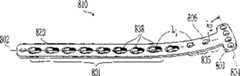
图10是图1所示骨板的平面图,其具有备选的接骨螺钉构造;Figure 10 is a plan view of the bone plate shown in Figure 1 with an alternative bone screw configuration;
图11A是设在根据本发明一个实施例的骨板中的组合孔的顶视图;11A is a top view of a combination hole provided in a bone plate according to one embodiment of the present invention;
图11B是图11A所示组合孔沿着图11A中的线XII-XII的剖视图;Fig. 11B is a sectional view of the combination hole shown in Fig. 11A along line XII-XII in Fig. 11A;
图12A是组合孔的不同实施例的顶视图;Figure 12A is a top view of a different embodiment of a combination hole;
图12B是图12A所示组合孔沿着图12A中的线A-A的剖视图;Fig. 12B is a sectional view of the combination hole shown in Fig. 12A along the line A-A in Fig. 12A;
图13是根据本发明的骨板的另一说明性实施例的剖视图;13 is a cross-sectional view of another illustrative embodiment of a bone plate according to the present invention;
图14是图1所示骨板3的下表面的局部透视图,其中骨板的一部分以剖面图显示;Figure 14 is a partial perspective view of the lower surface of the bone plate 3 shown in Figure 1, with a portion of the bone plate shown in cross-section;
图15是根据本发明的骨板的另一说明性实施例的侧视图;15 is a side view of another illustrative embodiment of a bone plate according to the present invention;
图16是图15所示骨板的顶视图;Figure 16 is a top view of the bone plate shown in Figure 15;
图17是图15所示骨板的局部透视图;Figure 17 is a partial perspective view of the bone plate shown in Figure 15;
图18是根据本发明的骨板的另一说明性实施例的顶视图;Figure 18 is a top view of another illustrative embodiment of a bone plate according to the present invention;
图19是图18所示骨板沿着图18的线XIX-XIX的局部剖视图;Fig. 19 is a partial cross-sectional view of the bone plate shown in Fig. 18 along line XIX-XIX of Fig. 18;
图20是图18所示骨板沿着图18的线XX-XX的局部剖视图;Figure 20 is a partial sectional view of the bone plate shown in Figure 18 along the line XX-XX of Figure 18;
图21是图18所示骨板的局部透视图;Figure 21 is a partial perspective view of the bone plate shown in Figure 18;
图22是图18所示骨板的局部正面透视图;Figure 22 is a partial front perspective view of the bone plate shown in Figure 18;
图23是根据本发明的骨板的另一说明性实施例的顶视透视图;23 is a top perspective view of another illustrative embodiment of a bone plate according to the present invention;
图24是图23所示骨板的透视图;Figure 24 is a perspective view of the bone plate shown in Figure 23;
图25是图23所示骨板的另一透视图;Figure 25 is another perspective view of the bone plate shown in Figure 23;
图26是图23所示骨板的另一透视图;Figure 26 is another perspective view of the bone plate shown in Figure 23;
图27是图23所示骨板的另外一个透视图;和Figure 27 is another perspective view of the bone plate shown in Figure 23; and
图28是根据本发明的一个实施例的一种带部分螺纹的骨板孔的剖视图。28 is a cross-sectional view of a partially threaded bone plate hole in accordance with one embodiment of the present invention.
优选实施例的详细描述Detailed description of the preferred embodiment
为了方便起见,附图所示骨板的各实施例中的相同或等效的部件用相同的标号来表示。另外,在以下描述中,涉及方位或方向的任何引用主要是为了描述方便起见,并非意味着对本发明的范围有任何限制。For convenience, the same or equivalent components in the various embodiments of the bone plates shown in the figures are designated by the same reference numerals. In addition, in the following description, any references to positions or directions are mainly for the convenience of description, and do not imply any limitation on the scope of the present invention.
骨板10的第一说明性实施例如图1所示。图1所示骨板10在尺寸上设置并构造成用于内部固定骨折的股骨F的近端部分。然而,本领域的普通技术人员可以认识和理解到,本发明的原理可适用于这样的骨板,其可用来固定人体和/或动物的其它骨如长骨,以及用于长骨的不同部分(例如近端胫骨、远端股骨等等)。A first illustrative embodiment of a
如图1和2所示,骨板10具有纵轴线15,并且包括上表面20和下表面22。骨板10可由生物相容性材料构成,例如钛、钛合金、不锈钢、可再吸收性材料和同种异体移植物,然而本领域的普通技术人员可以认识和理解到,可以使用任何生物相容性材料。如下更详细描述并且大体上如图1和3所示,骨板10构造成用于容纳多个骨锚固件110,115,120,125。骨锚固件110,115,120和125在图1中显示为接骨螺钉,然而也可以使用本领域的普通技术人员已知的其它类型的骨锚固件,例如叶片、钉子和销等等。骨板10和螺钉110,115的接合可形成桁架构造128,用于将骨板10有效地锚固在骨折的股骨的近端部分或其它骨上。下表面22可直接接触骨F,如图所示,或者可保持离骨表面有一定距离,以便有助于改善骨折部位的血液流通。As shown in FIGS. 1 and 2 ,
现在参见图3,显示了骨板10的剖视图。骨板10可包括第一孔24和第二孔28。第一孔24可限定中心轴线26,第一骨锚固件的轴部分将沿着该中心轴线26延伸,第二孔28可限定中心轴线30,第二骨锚固件的轴将沿着该中心轴线30延伸。第一孔24和第二孔28可构造成使得中心轴线26,30限定了单平面,并且在下表面22之下的点32处在该平面内相交。中心轴线26,30的相交可限定角度α,其优选为锐角,更优选在大约30°和大约60°之间。第一孔24的中心轴线26可基本上垂直于骨板10的下表面22,或者垂直于骨板10插入其中的骨F的外表面。例如,中心轴线26优选可定向成相对于骨板10的下表面22成大约95°。第二孔28的中心轴线30可相对于骨板10的下表面22成锐角,或者相对于骨板10插入其中的骨F的外部成锐角。骨板10还可包括如图3和4所示的至少两个导孔18,用于容纳和引导导线。Referring now to FIG. 3 , a cross-sectional view of
第一和第二孔24,28各自可构造成用于接合骨锚固件的头。更优选的是,第一和第二孔24,28可构造成用于与骨锚固件固定和锁定在一起,更优选用于将骨锚固件相对于骨板10的下表面22或骨板10插入其中的骨外表面固定在固定的预定方位,例如,通过螺纹式接合、干涉配合或压配合,或者本领域的普通技术人员已知的用于将板10与螺钉头结合起来的任何其它形式来实现。骨锚固件固定在板上,使得其轴或柄将沿着骨板10中的孔24,28的中心轴线26,30而延伸。在如图3所示的说明性实施例中,孔24,28是带螺纹的,用于分别与具有螺纹头的骨锚固件相接合。Each of the first and
这种骨锚固件的一个示例如图6和图7所示。接骨螺钉100限定了中心轴线102、带尖端105的螺纹柄104形式的轴,以及螺纹头106。接骨螺钉100例如可由钛、钛合金、不锈钢、可再吸收性材料如聚合物、同种异体移植物或本领域中已知的其它生物相容性材料构成。接骨螺钉100优选在成分和强度上与骨板10相容。接骨螺钉100可以是中空的,具有如图7所示的从上表面103的头106延伸至尖端105的通孔或通道107,以用于将器械如导线引入骨折部位中。An example of such a bone anchor is shown in FIGS. 6 and 7 . Bone screw 100 defines a
可与第一和第二孔24,28固定并锁定接合的另一骨锚固件是如图8和9所示的螺旋叶片310。叶片310限定了纵轴线302,并且具有近端306、远端304以及螺旋槽307形式的外表面308,但也可以采用其它的构造。螺旋叶片310可以是中空的,具有如图所示的中心通道305,或者可以为大致实心的。叶片310的近端306可通过压配合或干涉配合而接合在第一或第二孔24,28中,然而,本发明并不限于骨板和骨锚固件之间的任何特定结合形式。Another bone anchor that can be fixedly and lockingly engaged with the first and
回头参见图3,螺纹孔24,28可通过接骨螺钉100的螺纹头106单独地接合,以形成板和螺纹头106之间的螺纹式锁定接合,从而沿着中心轴线26,30来对准柄104和中心轴线102。螺纹孔24,28的内螺纹型式和螺纹头106的相配螺纹型式优选可具有带60°螺纹角度的螺纹牙形,但也可以采用其它的螺纹型式。骨板10和螺纹头106的螺纹式接合防止了骨板相对于与螺纹孔24,28相接合的接骨螺钉100产生运动,并且锁定了中心轴线102相对于板10的角位置以及彼此之间的角位置。通过将接骨螺钉的螺纹柄104锚固在断骨上并且螺纹头106与螺纹孔24,28锁定接合,这样骨板10就锚固在骨上。根据螺纹柄104锚固到骨中的深度,骨板10的下表面22可直接接触到骨表面,或者可附着于骨表面上且与之间隔开一定距离。另外,柄104具有足够的长度,以便跨过骨F的两骨折段之间的骨折部位的间隙,任一螺纹孔24,28及其中心轴线26,30可将柄104以一定的角度相对于板10对准,以便通过将螺纹头106锁定在螺纹孔24,28中来减小骨折部位的间隙。Referring back to FIG. 3 , the threaded
再次参见图1和3,由于螺纹孔24,28具有其中心轴线26,30在骨板10的下表面22以下的点32处相交的构造,因此接骨螺钉110,115与螺纹孔24,28的螺纹式接合将在骨表面以下形成桁架128。该桁架构造用于增加骨板10的锚固件在断骨上的稳定性。另外,桁架128用于在骨板10和锚固的接骨螺钉110,115上更均匀地分配载荷和应力。这些应力将集中在接骨螺钉110,115的螺纹头106和骨板10之间的接合处。如图1所示,通过接骨螺钉110,115与螺纹孔24,28相接合,接骨螺钉110,115可在骨表面F以下的相交点32处或其附近彼此接触。更优选的是,第二接骨螺钉115的尖端105可在第一接骨螺钉110的尖端105处与第一接骨螺钉110接触,大体上如图1所示,或者在沿着第一接骨螺钉110的柄104另一位置与第一接骨螺钉110接触,如图10所示。或者,接骨螺钉110,115彼此不接触;然而它们的中心轴线102可相交以限定平面,并由此而可操作地使接骨螺钉110,115彼此相关联,以便更均匀地分配螺纹式螺钉头106与板10的界面处所经受的载荷和应力。Referring again to FIGS. 1 and 3, since the threaded
如图3和4所示,螺纹孔24,28可以在从骨板10的上表面20至下表面22的方向上是锥形渐缩的。孔24,28的这种渐缩可有助于孔24,28的螺纹和接骨螺钉110,115的头106上的螺纹之间的对准。或者,螺纹孔24,28可为大致圆柱形、部分球形或者本领域中已知的其它形状。如图5更清楚地所示,螺纹孔24,28的中心轴线26,30可限定平面,其与基本上平分骨板10并且包括纵轴线15的平面相交并且相对于该平面成一定角度β。根据一个优选实施例,角度β可在0°至大约60°的范围内,或者在0°至至大约15°的范围内,或者为大约3°至大约6°,然而其它角度也是可以的。As shown in FIGS. 3 and 4 , the threaded
如图2和3所示,骨板10可包括第三孔34,其限定了用于接合第三骨锚固件的头的中心轴线36,出于说明性目的,第三骨锚固件在图1和5中显示为接骨螺钉120。第三孔34可类似地构造成螺纹孔26,28,以便包括用于与接骨螺钉120的螺纹头螺纹式接合的螺纹。第三螺纹孔34可在从骨板10的上表面20至下表面22的方向上是锥形渐缩的,或者,螺纹孔34可为大致圆柱形、部分球形或者本领域中已知的其它形状。第三螺纹孔34可设在螺纹孔24,28之间。具体参见图5,第三螺纹孔34的中心轴线36可与由第一和第二螺纹孔24,28的中心轴线26,30所限定的平面相交,并且相对于该平面成一定角度δ。角度δ可为大约0°至大约15°,或者为大约5°至大约8°,但其它角度也是可以的。参见图2,螺纹孔24,28,34可沿着纵轴线15彼此相对地定位和间隔开。As shown in FIGS. 2 and 3 , the
第三孔34的中心轴线36可构造成与第一孔24的轴线26相交,作为附加或作为备选,中心轴线36可构造成与第二钻孔28的中心轴线30相交。第三骨锚固件120可在接骨螺钉110的尖端105或在沿着第一接骨螺钉110的轴104的另一位置处接触第一接骨螺钉110。作为备选或者作为附加,第三螺钉120可在尖端105或在沿着第二接骨螺钉115的柄104的某些其它位置接触第二接骨螺钉115。在一个实施例中,第三接骨螺钉可沿着其各自的长度而分别接触第一和第二接骨螺钉110,115,并且全部三个接骨螺钉可在其各自的尖端105相互接触。Additionally or alternatively, the
现在参见图28。在另一实施例中,作为替代或者作为附加而具有任意的上述孔,骨板10可具有部分螺纹式的孔90。孔90可从骨板10的上表面20延伸至下表面22。孔90在其最上表面和在其最下表面的直径可彼此相等或彼此接近。孔可在板10的最上表面20和最下表面22处最宽。See Figure 28 now. In another embodiment, the
如图28所示,孔90可具有三个区:上区92、中区94和下区96。孔90的上区92可具有无螺纹的内表面93,其优选为光滑的,但也可以设置纹饰。在一个优选实施例中,上区92可在从板10的顶面至孔90的上区92与中区94相交处具有向内弯曲的锥形,优选为凹形,更优选为球形。孔90的上区92优选在其与中区94相交处最窄。在一个优选实施例中,上区可包括板10的大约25%至大约35%的厚度。在一个优选实施例中,上区92在该区的最宽点处的直径可为大约6毫米,在该区的最窄点处可为大约4毫米。As shown in FIG. 28 , aperture 90 may have three zones: an upper zone 92 , a middle zone 94 and a lower zone 96 . The upper region 92 of the bore 90 may have an unthreaded inner surface 93, which is preferably smooth, but may also be textured. In a preferred embodiment, the upper region 92 may have an inwardly curved tapered, preferably concave, more preferably spherical shape at the intersection of the upper region 92 and the middle region 94 from the top surface of the
孔90的中区94可具有带螺纹的内表面95。带螺纹的内表面95可在从板10的上表面至下表面的方向上具有向内渐缩的锥形。在一个优选实施例中,带螺纹的内表面95可以大约5°至15°、优选为大约10°的角度α而形成锥度。中区94可为孔90的最窄区(即最小直径的区)。在一个优选实施例中,中区94可包括板10的大约40%至50%的厚度。在一个优选实施例中,中区94的直径可仅仅发生轻微的变化(由于较浅的锥形渐缩),并且可以为大约4毫米。中区94的直径或锥度当然可根据螺钉的尺寸和/或锥度而变化。Central region 94 of bore 90 may have a threaded inner surface 95 . The threaded inner surface 95 may have an inwardly tapering taper in the direction from the upper surface to the lower surface of the
孔90的下区96可具有无螺纹的内表面97,其优选为光滑的,但也可以设置纹饰。在一个优选实施例中,下区96可从其与中区94相交处至板的下表面而具有向外渐缩锥形。在一个优选实施例中,下区96可以大约35°至55°、优选为大约45°的角度β而向外形成锥度。在一个优选实施例中,下区96可包括板的大约20%至35%的厚度。在一个优选实施例中,下区96在该区的最窄点处的直径可以为大约4毫米,并且在该区的最宽点处的直径可以为大约6毫米。The lower region 96 of the bore 90 may have an unthreaded inner surface 97, which is preferably smooth, but may also be textured. In a preferred embodiment, the lower zone 96 may have an outwardly tapered shape from where it meets the central zone 94 to the lower surface of the plate. In a preferred embodiment, the lower region 96 may taper outwardly at an angle β of about 35° to 55°, preferably about 45°. In a preferred embodiment, the lower region 96 may comprise approximately 20% to 35% of the thickness of the plate. In a preferred embodiment, the lower zone 96 may have a diameter of about 4 millimeters at the narrowest point of the zone and a diameter of about 6 millimeters at the widest point of the zone.
不同类型的螺钉可与孔90一起使用。一种类型的螺钉是具有锥形螺纹头的螺钉。螺钉头部的外螺纹可与孔90的中区94的内螺纹95相配。这种螺纹头螺钉可以仅仅一个角度(相对于板)来插入,其可通过板10中的螺纹95来固定。Different types of screws can be used with holes 90 . One type of screw is a screw with a tapered thread head. The external threads of the screw head can mate with the internal threads 95 of the central region 94 of the bore 90 . Such threaded head screws can only be inserted at an angle (relative to the plate), which can be secured by the threads 95 in the
可与孔90一起使用的第二类型的螺钉是带螺纹轴、但带有无螺纹头的螺钉。无螺纹头式螺钉可以许多角度中的任一角度而插入孔90中。孔90的下区96的向外渐缩锥形(显示于表面97处)提供了空间,用于螺钉轴以相对于孔90的中心成一定角度地插入。同样地,孔90的上区92的弯曲向内渐缩提供了在无螺纹头的螺钉以一定角度插入时用于承靠螺钉头的承座(在表面93)。螺纹头的螺钉可与同轴的组合孔90一起使用,其使用方式与上述无螺纹头的螺钉的使用方式相同。A second type of screw that can be used with hole 90 is a screw with a threaded shaft but with an unthreaded head. A threadless head screw can be inserted into hole 90 at any of a number of angles. The outward tapering of the lower region 96 of the hole 90 (shown at surface 97 ) provides space for the screw shaft to be inserted at an angle relative to the center of the hole 90 . Likewise, the curved inward taper of the upper region 92 of the bore 90 provides a seat (at surface 93) for bearing the screw head when a screw without a threaded head is inserted at an angle. A threaded head screw may be used with the coaxial combination hole 90 in the same manner as the non-threaded head screw described above.
尽管实际上任何类型的骨板可受益于同轴的组合孔90,但同轴的组合孔尤其可用于公共的骨联合板和其它较小的骨板。Although virtually any type of bone plate can benefit from coaxial combination holes 90, coaxial combination holes are particularly useful for common osseosynthesis plates and other smaller bone plates.
再次参见图1,骨板10可包括基本上平面的第一部分6,以及大致弯曲以符合骨头部、例如股骨F的近端部分的第二部分8。骨板10或者可构造成直板,或者作为附加或另选而构造成包括除了轴部分之外的扩张部分。第一部分6的下表面22可直接地接合骨表面,在这种情形下,第一部分6可包括多个凹口12,其围绕纵轴线15间隔开以用于减小骨板10和骨表面之间的接触,以便有助于增加骨折部位的血液循环。螺纹孔24,28优选位于骨板10的第二部分8内,其中第二部分8符合并顺应于骨的头部。Referring again to FIG. 1 ,
骨板10可设有任何数量的孔,以便可适用于特定的手术应用。例如,如图3所示,骨板10可包括一个或多个组合孔38,其基本上类似于美国专利公开No.2002/0183752 A1中所述的组合孔,该专利通过引用而结合于本文中。如图11A所示,各组合孔38包括第一大致圆形部分44和第二延长部分46。圆形部分44和延长部分46彼此重叠,并因此而彼此连通。圆形部分44的外周边限定了第一中心点48以及直径D。延长部分46的外周边限定了第二中心点50。延长部分46的外周边还限定了长轴线55以及基本上垂直于长轴线55的短轴线57。根据本发明的一个实施例,长轴线55可基本上平行于骨板10的纵轴线15。另外,长轴线55可沿着纵轴线15设置,其中第一和第二中心点48,50设在纵轴线15上,然而其它的构造也是可行的。组合孔38还可平行于纵轴线15但与其偏开,或者组合孔可相对于纵轴线15偏开。
延长部分46可构造成以及在尺寸上设置成与接骨螺钉的大致球形螺钉头(未示出)相接合。作为附加或另选,带有或没带螺纹的锥形螺钉头可与延长部分46相接合。如图11A和11B所示,延长部分46可具有凹形的大致球形部分或凹口60,其朝着骨板10的上表面20敞开。当具有球形头的接骨螺钉的轴偏心地设在延长部分46(朝着图10中的右侧)中时,球形头可接合凹口60并且偏压骨板10,以便提供对骨折部位的压紧。另外,组合孔38的一部分可沿着骨板10的下表面22下凹,以便限定球形凹口61。The
仍然参见图11A和11B,圆形部分44可构造成以及在尺寸上设置成接合接骨螺钉(未示出)的螺纹头。内螺纹62可设在圆形部分44上。螺纹62可处于单平面内或处于若干平面内。这些平面可平行于上表面20和/或下表面22。根据所示的说明性实施例,螺纹62在骨板的基本上整个厚度上从上表面20延伸至下表面22。内螺纹62可形成大约190°至大约280°的角度。参见图1,组合孔38显示为与接骨螺钉125相接合。Still referring to FIGS. 11A and 11B ,
现在参见图12A。在另一实施例中,作为替代或者作为附加而具有组合孔38,骨板10可具有至少一个不同类型的组合孔80。各组合孔80可具有两个大致圆形部分83和84。圆形部分83和84可彼此重叠,并且可彼此连通。See now Figure 12A. In another embodiment, the
内螺纹87可设在圆形部分83上。内螺纹88可设在圆形部分84上。螺纹87和88可基本上在骨板的整个厚度上从上表面20延伸至下表面22。图12B显示了圆形部分84的螺纹88延伸过骨板的整个厚度。螺纹87和88可以具有相同方向上的螺纹(例如要求顺时针旋转以便插入带螺纹头的螺钉),或者相反方向上的螺纹。螺纹87和88可处于单平面或处于若干平面内。螺纹的平面可平行于骨板10的上表面20和/或下表面22,或者螺纹所形成的平面可相对于上表面20和/或下表面22成角度。螺纹87和88的各螺纹可形成大约190°至大约270°的角度。螺纹87和88可以相同的角度或彼此不同的角度而延伸。螺纹87和88可具有锥形向内渐缩。组合孔80可以与组合孔38设在骨板10内的相同方式而设在骨板10内,如上所述,或者处于不同的设置中。另外,组合孔80可用于还包括组合孔38以及本说明书中所述的任何其它孔的骨板中。
图13显示了一个备选的优选实施例,骨板910构造成基本上类似于骨板10。骨板910和骨板10之间的显著区别在于,骨板910可包括挂钩部分970。挂钩部分970可连接在第二部分908上,与之形成一体,或者设在其端部上。与针对骨板10的第二部分8如上所述的一样,第二部分908可类似地大致弯曲,以便符合骨F的头部,例如股骨头部。挂钩部分970包括骨接合边缘972,用于钻入或穿入骨组织中。更具体而言,骨板910可沿着近端股骨F定位,使得第二部分908可缠绕或顺应符合更大转节的一部分,并且挂钩部分970可与梨状肌部位相接合。骨接合边缘972可构造成用于穿透骨表面,以便更有效地抓紧骨F,从而允许外科医生利用骨板910来作为杠杆以抵抗骨F的骨折段周围的肌肉和肌腱的拉伸,并且正确地对准骨F的断片。骨接合边缘972穿透骨F的深度可通过更大转节与骨板910的下表面922之间的干涉来得以限制。一旦骨F正确地对准,与孔924,928,934相接合并通过这些孔固定地定位的接骨螺钉就可插入到骨中,以便将骨板910相对于骨F固定。FIG. 13 shows an alternative preferred embodiment,
如图13所示,挂钩部分970构造成朝着骨板910的第一部分906向内弯曲并终止于下表面922以下的点处,以便不会与接合在第一孔924中的骨锚固件发生干涉。如图14所示,边缘972优选可通过两个间隔开的爪形件973,974形成,然而,也可以采用其它的构造来有助于挂钩972与骨组织的牢固接合。As shown in FIG. 13 , the
图15-27显示了构造成用于固定其它长骨、例如胫骨或肱骨的骨板的备选实施例。参见显示了一个备选实施例的图15-17,骨板410包括上表面420、下表面422、具有第一纵轴线402的第一段401,以及具有第二纵轴线404的第二段403。与骨板10一样,骨板410的下表面422可直接地接触骨表面,或者,下表面422的至少一部分可保持离骨表面有一段距离,以便有助于改善骨折部位的血液流动。如图15所示,沿着下表面422设置有凹口412,以便有助于骨折部位的血液流动。现在参见图18,骨板410还可包括过渡段405,其将第一段401连接在第二段403上,使得第一纵轴线402和第二纵轴线404限定了两者之间的角度λ。第一、第二和过渡段401,403,405可由单件材料形成,然而其它的构造也是可以的,例如,这些材料件可焊接或以其它方式结合在一起。另外,第一、第二和过渡段401,403,405可在整个骨板上具有基本上相同的宽度,并且可以在形状上为大致平行四边形。然而,其它的构造也是可以的,例如,段401,403,405中的至少一个可以是扩口的,或具有大致多边形的形状。15-27 illustrate alternative embodiments of bone plates configured for fixation of other long bones, such as the tibia or humerus. 15-17 which illustrate an alternative embodiment, a
参见图17,骨板可包括分别具有中心轴线426,428的至少第一孔424和第二孔428。第一和第二孔424,428以与骨板10的孔24,28基本上类似的方式来构成,使得它们能够接合骨锚固件,例如如上所述的接骨螺钉100、螺旋叶片310,或如上所述的其它类型的骨锚固件。应当理解,第一和第二孔424,428可构造成通过螺纹式接合、干涉配合或压配合或者本领域的普通技术人员已知的将板与锚固件头结合在一起的任何其它形式,而用于与骨锚固件的头相接合。如图所示,第一和第二孔424,428优选构造成可分别形成与接骨螺钉510,515的螺纹式锁定接合,接骨螺钉510,515类似于接骨螺钉100,并且具有螺纹头506(未示出)、轴504和尖端505。第一和第二孔424,428可包括内螺纹,并且具有从上表面420至下表面422的锥形渐缩。锁定接合将接骨螺钉510,515固定在板410上,使得轴504沿着骨板410中的孔424,428的中心轴线426,430延伸。另外,第一和第二孔424,428优选构造成使得中心轴线426,430在骨板410的下表面422以下的点432处相交。接骨螺钉510,515与第一和第二螺纹孔424,428的螺纹式接合可以如上针对骨板10所述的方式来形成骨表面之下的桁架528。接骨螺钉510可基本上垂直于骨板410的下表面422或者接骨螺钉510插入其中的骨的表面外部。接骨螺钉515可相对于骨板的下表面或接骨螺钉510插入其中的骨外部而形成锐角。螺钉515可在接骨螺钉510的尖端105、或者沿着接骨螺钉510的轴104的任意处而接触到接骨螺钉510。根据一个说明性实施例,通过中心轴线426,430的相交所形成的角度可在大约30°至大约60°的范围内,然而其它的角度也是可以的。Referring to Fig. 17, the bone plate may include at least a
第一和第二孔424,428可处于骨板410的相同段中,或者作为备选,第一孔424可处在与第二孔428所在段不同的段中。在第一和第二孔424,428处于骨板410的相同段中之处,中心轴线426,430的相交所限定的平面可与平分骨板410的其中第一和第二孔424,428所处的相同段的平面共面。或者,中心轴线426,430的相交所限定的平面可相对于平分骨板410的平面(未示出)成角度。平分平面与由中心轴线426,430相交所限定的平面所形成的角度可在大约0°至大约60°的范围内,或在大约0°至至大约15°的范围内,或在大约3°至大约6°的范围内。The first and
另一实施例,即如图18-22所示的骨板610,包括第一和第二孔624,628,如图21所示,它们具有相交于标号632处的第一和第二中心轴线626,630。另外一个实施例,即如图25-29所示的骨板810,包括第一和第二孔824,828,如图25所示,它们具有相交于标号832处的中心轴线826,830。可以理解,骨板610的第一和第二孔624,628和骨板810的第一和第二孔824,828可以可变动地构造成上述骨板410的第一和第二孔424,428。更具体而言,骨锚固件与板610和/或810的接合可以预定的角度来固定骨锚固件,以便分别形成如图21所示的桁架728,以及如图26所示的桁架1128,它们处于骨表面之下,如同当前针对骨板10和410所述。第一和第二接骨螺钉可沿着其各自的轴或尖端而彼此接触。另外,骨板610和810可选择性地锚固在骨上,使得它们的下表面622,822或者直接地接触骨表面,同时带有或不带有用于促进骨折部位的血液循环的凹口612,812;或者,骨板610,810可以一定的相对距离而与骨表面间隔开。Another embodiment, a
图15-27显示了骨板410,610,810,以及第一段401,601,801与第二段403,603,803以各种构造通过过渡段405,605,805而各自地相连;然而,其它的构造也是可以的。再次参见图16,形成于第一和第二中心轴线402,404之间的夹角λ可以是钝角,其角度范围为大约195°至大约175°,或者为120°至160°,或者该角度λ优选为大约153°。或者,夹角λ可以基本上为锐角,角度范围为大约15°至大约85°,优选为大约22°。另外,角度λ可以为直角,其中第二段403基本上垂直于第一段401。15-27
如图15-27所示,骨板410,610,810的第一和第二段可具有不同的长度,例如,第一段可以比第二段更长。这些构造基本上类似于美国专利公开2002/0183752A1中所示和所述的构造,该专利的全部内容通过引用而结合于本文中。具体参见图20和25,骨板610,810可以分别为大致L形或T形。如图19所示,第一段601可处在与第二段603所处的平面不同的平面内。例如,过渡段605可以是弯曲的,使得第一段601的下表面622处于第一平面内,并且第二段603的下表面622处在不同于第一平面的第二平面内。作为对此的备选或附加,过渡段605可以是扭曲的,因此纵轴线602,604一侧的下表面622所处的平面不同于纵轴线602,604另一侧的下表面622所处的平面。在骨板410,610,810必须设在骨的弯曲部分上、例如近端胫骨的内髁和外髁上时,这会是有利的。As shown in FIGS. 15-27, the first and second segments of the
现在参见图23,图中显示了另一骨板810,其中,过渡段805可限定第三纵轴线806,并且可构造成与第一段801的第一纵轴线802一起限定了第一夹角λ1,以及与第二段803的第二纵轴线804一起限定了第二夹角λ2。过渡段805可如上所述地为挠曲的、弯曲的或扭曲的,或者,过渡段805可另外扭曲成使得上表面820基本上呈S形。骨板410,610,810的第一和第二段401,403;601,603;801,803还可以是扭曲的或挠曲的,以便顺应骨表面。例如,现在参见图20,图中显示了骨板610的第二段603的剖视图,其中,下表面622可沿着第二纵轴线604挠曲或弯曲,以便限定曲率半径R。另外,第一段601的一部分可围绕第一纵轴线602扭曲。Referring now to FIG. 23 , another
骨板410,610,810还可设有限定了第三中心轴线的至少第三孔,其中,第三孔可以可变动地构造成如上所述的第一和第二孔424,428。第三孔可与骨锚固件的头或端部相接合,骨锚固件例如为具有轴104和尖端105的接骨螺钉100。具体参见图18和19,作为说明性示例的骨板610包括具有中心轴线636的第三孔634。第三孔634可构造成用于与接骨螺钉100螺纹式锁定接合,以便沿着第三中心轴线636来对准接骨螺钉100的轴104。第三孔634的第三中心轴线636可以这种角度来设置,以便与第一和第二孔624,628的第一和第二中心轴线626,630中的至少一条相交。第三中心轴线636可设置成相对于第一和第二中心轴线626,630所形成的平面成一定角度。The
在图21和22中显示了与接骨螺钉710,715,720相接合的骨板610,接骨螺钉710,715,720各自与第一、第二和第三孔624,628,634相接合。接骨螺钉710,715与第一和第二孔624,628螺纹式地相接合,以形成用于将骨板610刚性地锚固在断骨上的桁架728。第三接骨螺钉720可以与骨板610螺纹式锁定接合,使得第三接骨螺钉720的轴104的至少一部分、优选为尖端105可接触或几乎接触第一或第二接骨螺钉710,715的轴中的至少一根轴,以便进一步加强桁架728和骨板610的锚固件。第三孔634可设在骨板的与第一和第二孔624,628中任一孔所处的段相同的段中。或者,第三孔634可设在与第一和第二孔624,628中任一孔所处的段不同的段中。例如,如图21所示,第三孔634与第二孔628一同位于过渡段605中。第一孔624位于骨板610的第二段603中。
如图15-27所示,骨板410,610和810可设有任何数量的孔,其可适用于特定的手术应用。这些另外的孔中的任一孔可以如上所述地通过与骨板410的第一和第二孔424,428相类似且完全可变动的方式来构成。As shown in FIGS. 15-27, the
现在参见图21和22,骨板610的第二段603可包括具有中心轴线642,646,650的另外的孔640,644,648。如图21所示,这些另外的孔可构造成用于与具有轴704的接骨螺钉725,730,735的头706螺纹式锁定接合,其中轴704与中心轴线642,646,650对准。中心轴线642,646,650可设置成相对于第一和第二中心轴线626,630成一定角度,使得接骨螺钉725,730,735的轴接触到、几乎接触到或基本上平行于接骨螺钉710,715,其显示为与第一和第二孔624,628相接合。根据既定手术场合的需要,类似地构成为640,644,648的另外的孔可设在骨板410,610,810的第一段401,601,801、第二段403,603,803或过渡段405,605,805的任意段中。如图21的说明性实施例中所示,过渡段605包括与接骨螺钉740相接合的孔652。或者,骨板610中的螺钉孔可构造成使得骨锚固件、例如锥形螺钉可与孔624相接合,并且第二接骨螺钉可与孔634相接合,使得螺钉接触或几乎接触以形成第一桁架结构。作为对此的备选或附加,第三接骨螺钉可与孔628相接合,并且第四接骨螺钉可与孔648相接合,使得第三和第四螺钉接触或几乎接触以形成第二桁架结构。或者,第一接骨螺钉和第三接骨螺钉可接触或几乎接触以形成第一桁架结构,并且第二接骨螺钉和第四接骨螺钉可接触或几乎接触以形成第二桁架结构。作为备选或作为附加,第五骨锚固件可与接骨螺钉孔652相接合,第六接骨螺钉可与孔644相接合。第五和第六接骨螺钉可接触或近似接触以形成第三桁架结构。Referring now to FIGS. 21 and 22 , the
第一、第二和第三桁架结构可通过任意种构造的骨锚固件的任意种组合来形成。另外,骨板610可根据需要而设有另外的孔,以形成所需数量的桁架结构。另外,第一、第二、第三和任何另外的桁架结构可接触或不接触或近似接触一个或多个其它桁架结构。优选的是,第二、第三和另外的桁架结构可成一定角度,以便与第一桁架结构所限定的平面相交。The first, second and third truss structures may be formed by any combination of bone anchors in any configuration. In addition, the
另一示例在骨板410的实施例中所示。在图17中显示了设在第一段401中的孔440,444,其相对于骨板410的第二段403中的第一和第二孔424,428间隔开。孔440,444优选可分别构造成用于与骨锚固件525,530的螺纹头506(未示出)螺纹式锁定接合,使得轴104可彼此岔开,并且与接合在第一和第二孔424,428中的骨紧固件510,515的轴504岔开。另一说明性示例显示为第六实施例,即图25中的骨板810。第一孔824设在第二段803中,第二孔828设在第一段801中。参见图25和26,第三孔834位于过渡段805中,并且构造成使得与第三孔834相接合的接骨螺钉1120的轴1104将接触或近似接触到接合在第一和第二孔824,828中的接骨螺钉1110,1115的其中一根轴1104。另外的孔840,844设在第二段803中,并且构造成以便以一定方式与接骨螺钉1125,1130相接合,使得轴1104将在朝向接合在第一和第二孔824,828中的接骨螺钉1110,1115的方向上对准,从而几乎形成接触。Another example is shown in the embodiment of
骨板410,610,810还可包括螺纹式的或无螺纹式的另外的孔,用于容纳用于将骨板410,610,810锚固在骨上的另外的骨锚固件。例如,骨板410,610,810可包括多个组合孔438,638,838,其类似于参考图11A和11B如上所述的组合孔38。组合孔438,638,838均可优选位于骨板410,610,810的第一段401,601,801中。另外,骨板410,610,810可包括构造成用于容纳导线或其它器具的一个或多个孔,例如用于容纳用于对骨折部位加压的器具的图2所示孔72,或者例如如图20所示,第二段603包括构造成用于容纳导线或其它器具的多个孔618。The
骨板10,910,410,610和810可在长度和宽度上有变化,但长度一般超过宽度,以便限定大致纵向的部件。骨板的长度可在大约50毫米至大约500毫米的范围内。骨板10可优选具有大约135毫米至大约435毫米的长度。骨板910可优选具有大约145毫米至大约480毫米的长度。骨板410可优选具有大约75毫米至大约235毫米的长度。骨板610可优选具有大约81毫米至大约240毫米的长度。骨板810可优选具有大约105毫米至大约350毫米的长度。骨板10,910,410,610和810的任意段还可具有从大约5毫米至大约10毫米至大约18毫米的宽度。在骨板的一段垂直于另一段时,骨板的最宽部分可达35毫米。板厚度也可为大约3毫米至大约5毫米。另外,骨板的厚度可沿着其长度变化。例如,如图1所示,骨板10的部分6一般具有渐缩的部分。第一段406,606和806一般也可具有渐缩的部分。所述的所有骨板可在骨板上的其它部位具有渐缩的部分,或者,板厚度可在剖面上有变化。
尽管已经在本文中公开了本发明的优选实施例和特征,然而可以理解,本领域的技术人员可以构思出大量的修改和实施例。所附权利要求旨在覆盖属于这些权利要求的真正实质和范围内的所有这类修改和实施例,所附权利要求并不限于或者受限于这些优选实施例或特征。Although preferred embodiments and features of this invention have been disclosed herein, it is understood that numerous modifications and embodiments can be devised by those skilled in the art. The appended claims are intended to cover all such modifications and embodiments as fall within the true spirit and scope of such claims, and the appended claims are not limited to or limited by these preferred embodiments or features.
Claims (114)
Translated fromChineseApplications Claiming Priority (3)
| Application Number | Priority Date | Filing Date | Title |
|---|---|---|---|
| US47427903P | 2003-05-30 | 2003-05-30 | |
| US60/474,279 | 2003-05-30 | ||
| PCT/US2004/017008WO2004107957A2 (en) | 2003-05-30 | 2004-05-28 | Bone plate |
Publications (2)
| Publication Number | Publication Date |
|---|---|
| CN1832706Atrue CN1832706A (en) | 2006-09-13 |
| CN1832706B CN1832706B (en) | 2013-11-20 |
Family
ID=33511596
Family Applications (1)
| Application Number | Title | Priority Date | Filing Date |
|---|---|---|---|
| CN2004800215243AExpired - LifetimeCN1832706B (en) | 2003-05-30 | 2004-05-28 | Bone plate |
Country Status (11)
| Country | Link |
|---|---|
| US (6) | US7951176B2 (en) |
| EP (1) | EP1633260B1 (en) |
| JP (2) | JP5308625B2 (en) |
| KR (1) | KR101131253B1 (en) |
| CN (1) | CN1832706B (en) |
| AU (1) | AU2004245023B2 (en) |
| BR (1) | BRPI0410858B8 (en) |
| CA (1) | CA2527249C (en) |
| NZ (1) | NZ544328A (en) |
| WO (1) | WO2004107957A2 (en) |
| ZA (1) | ZA200509650B (en) |
Cited By (9)
| Publication number | Priority date | Publication date | Assignee | Title |
|---|---|---|---|---|
| CN103169534A (en)* | 2011-12-20 | 2013-06-26 | 上海市第六人民医院 | Back outer side anatomy type locking bone fracture plate for tibia plateau |
| TWI465224B (en)* | 2011-11-15 | 2014-12-21 | ||
| CN105193488A (en)* | 2015-08-18 | 2015-12-30 | 李照文 | Arc-shaped steel plate for fixation of fracture of femur |
| CN106163434A (en)* | 2014-04-18 | 2016-11-23 | 白惠善 | Fixing utensil for opening hto art |
| CN106170259A (en)* | 2014-04-18 | 2016-11-30 | 白惠善 | Fixing utensil for opening hto art |
| CN107019550A (en)* | 2016-02-01 | 2017-08-08 | 爱派司生技股份有限公司 | Long bone fixing device |
| CN107205760A (en)* | 2015-01-16 | 2017-09-26 | 德普伊新特斯产品公司 | Washer plate |
| CN109310457A (en)* | 2016-05-31 | 2019-02-05 | 奥林巴斯泰尔茂生物材料株式会社 | Bone plate and bone plate system |
| CN110680563A (en)* | 2019-10-31 | 2020-01-14 | 北京爱康宜诚医疗器材有限公司 | sternum prosthesis |
Families Citing this family (233)
| Publication number | Priority date | Publication date | Assignee | Title |
|---|---|---|---|---|
| US5938664A (en)* | 1998-03-31 | 1999-08-17 | Zimmer, Inc. | Orthopaedic bone plate |
| US7282053B2 (en)* | 2003-03-27 | 2007-10-16 | Depuy Products, Inc. | Method of using fracture fixation plate for performing osteotomy |
| US20040153073A1 (en) | 2000-02-01 | 2004-08-05 | Hand Innovations, Inc. | Orthopedic fixation system including plate element with threaded holes having divergent axes |
| US7857838B2 (en)* | 2003-03-27 | 2010-12-28 | Depuy Products, Inc. | Anatomical distal radius fracture fixation plate |
| US8475504B2 (en)* | 2007-07-19 | 2013-07-02 | Acumed Llc | Method of bone fixation with slender spanning members disposed outside bone |
| US20110034925A1 (en)* | 2001-10-18 | 2011-02-10 | Orthoip, Llc | Lagwire system and method for the fixation of bone fractures |
| US20100268285A1 (en)* | 2001-10-18 | 2010-10-21 | Orthoip, Llc | Bone screw system and method for the fixation of bone fractures |
| US9060809B2 (en) | 2001-10-18 | 2015-06-23 | Orthoip, Llc | Lagwire system and method for the fixation of bone fractures |
| US8679167B2 (en) | 2001-10-18 | 2014-03-25 | Orthoip, Llc | System and method for a cap used in the fixation of bone fractures |
| US8828067B2 (en) | 2001-10-18 | 2014-09-09 | Orthoip, Llc | Bone screw system and method |
| US6736819B2 (en) | 2001-10-18 | 2004-05-18 | Kishore Tipirneni | System and method for fixation of bone fractures |
| US20090306718A1 (en)* | 2001-10-18 | 2009-12-10 | Orthoip, Llc | Filament and cap systems and methods for the fixation of bone fractures |
| US20090131990A1 (en)* | 2001-10-18 | 2009-05-21 | Kishore Tipirneni | Bone screw system and method |
| US8702768B2 (en) | 2001-10-18 | 2014-04-22 | Orthoip, Llc | Cannulated bone screw system and method |
| US7780710B2 (en) | 2004-01-23 | 2010-08-24 | Depuy Products, Inc. | System for stabilization of fractures of convex articular bone surfaces including subchondral support structure |
| US7938850B2 (en)* | 2002-05-30 | 2011-05-10 | Depuy Products, Inc. | Nail plate |
| WO2004014243A1 (en) | 2002-08-10 | 2004-02-19 | William H Simon | Method and apparatus for repairing the mid-food region via an intermedullary nail |
| US7179260B2 (en)* | 2003-09-29 | 2007-02-20 | Smith & Nephew, Inc. | Bone plates and bone plate assemblies |
| US20060129151A1 (en)* | 2002-08-28 | 2006-06-15 | Allen C W | Systems and methods for securing fractures using plates and cable clamps |
| US7780664B2 (en) | 2002-12-10 | 2010-08-24 | Depuy Products, Inc. | Endosteal nail |
| US7294130B2 (en)* | 2003-03-27 | 2007-11-13 | Depuy Products, Inc. | Distal radius fracture fixation plate having K-wire hole structured to fix a K-wire in one dimension relative to the plate |
| US7250053B2 (en)* | 2003-03-27 | 2007-07-31 | Depuy Products, Inc. | Low profile distal radius fracture fixation plate |
| US7635381B2 (en)* | 2003-03-27 | 2009-12-22 | Depuy Products, Inc. | Anatomical distal radius fracture fixation plate with fixed-angle K-wire holes defining a three-dimensional surface |
| GB0307648D0 (en)* | 2003-04-02 | 2003-05-07 | Benoist Girard Sas | Greater trochanter re-attachment device |
| US7776076B2 (en) | 2004-05-11 | 2010-08-17 | Synthes Usa, Llc | Bone plate |
| US7951176B2 (en) | 2003-05-30 | 2011-05-31 | Synthes Usa, Llc | Bone plate |
| US11259851B2 (en) | 2003-08-26 | 2022-03-01 | DePuy Synthes Products, Inc. | Bone plate |
| DE20321551U1 (en) | 2003-08-26 | 2007-12-27 | Synthes Gmbh | bone plate |
| US8105367B2 (en) | 2003-09-29 | 2012-01-31 | Smith & Nephew, Inc. | Bone plate and bone plate assemblies including polyaxial fasteners |
| US8182485B1 (en)* | 2003-11-21 | 2012-05-22 | Toby Orthopaedics, Llc | Fracture fixation system |
| US7001388B2 (en)* | 2004-01-23 | 2006-02-21 | Hand Innovations, Llc | System for stabilization of fractures of convex articular bone surfaces including subchondral support structure |
| WO2005072284A2 (en) | 2004-01-23 | 2005-08-11 | Depuy Products, Inc. | System for stabilization of fractures of convex articular bone surfaces including subchondral support structure |
| US8574268B2 (en) | 2004-01-26 | 2013-11-05 | DePuy Synthes Product, LLC | Highly-versatile variable-angle bone plate system |
| US11291484B2 (en) | 2004-01-26 | 2022-04-05 | DePuy Synthes Products, Inc. | Highly-versatile variable-angle bone plate system |
| WO2006091827A2 (en)* | 2005-02-25 | 2006-08-31 | Regents Of The University Of California | Device and template for canine humeral slide osteotomy |
| US10478179B2 (en)* | 2004-04-27 | 2019-11-19 | Covidien Lp | Absorbable fastener for hernia mesh fixation |
| US20060173458A1 (en)* | 2004-10-07 | 2006-08-03 | Micah Forstein | Bone fracture fixation system |
| US8394130B2 (en) | 2005-03-17 | 2013-03-12 | Biomet C.V. | Modular fracture fixation system |
| DE102005004841B4 (en)* | 2004-12-30 | 2009-10-29 | Königsee Implantate und Instrumente zur Osteosynthese GmbH | Osteosynthesis plate with a variety of holes for receiving bone screws |
| US8160928B2 (en)* | 2005-01-21 | 2012-04-17 | Ebay Inc. | Network-based commerce facility offer management methods and systems |
| CA2596266C (en)* | 2005-01-28 | 2015-03-31 | Depuy Products, Inc. | Nail plate system |
| US8197523B2 (en) | 2005-02-15 | 2012-06-12 | Apex Biomedical Company, Llc | Bone screw for positive locking but flexible engagement to a bone |
| US8740955B2 (en) | 2005-02-15 | 2014-06-03 | Zimmer, Inc. | Bone screw with multiple thread profiles for far cortical locking and flexible engagement to a bone |
| US20060264947A1 (en)* | 2005-05-20 | 2006-11-23 | Orbay Jorge L | Bone fixation system |
| US8382807B2 (en) | 2005-07-25 | 2013-02-26 | Smith & Nephew, Inc. | Systems and methods for using polyaxial plates |
| CA2616798C (en) | 2005-07-25 | 2014-01-28 | Smith & Nephew, Inc. | Systems and methods for using polyaxial plates |
| US7905909B2 (en) | 2005-09-19 | 2011-03-15 | Depuy Products, Inc. | Bone stabilization system including multi-directional threaded fixation element |
| KR101246113B1 (en) | 2005-10-25 | 2013-03-20 | 앤썸 오르소패딕스, 엘엘씨 | Bone fastening assembly and bushing and screw for use therewith |
| US8100952B2 (en)* | 2005-12-22 | 2012-01-24 | Anthem Orthopaedics Llc | Drug delivering bone plate and method and targeting device for use therewith |
| ES2298921T3 (en)* | 2005-12-23 | 2008-05-16 | Aap Implantate Ag | OSEA PLATE. |
| US8523921B2 (en)* | 2006-02-24 | 2013-09-03 | DePuy Synthes Products, LLC | Tibial plateau leveling osteotomy plate |
| US8021402B2 (en)* | 2006-03-07 | 2011-09-20 | Orthohelix Surgical Designs, Inc. | Distal radius plate |
| BRPI0601069B1 (en)* | 2006-03-17 | 2014-10-14 | Gm Dos Reis Ind E Com Ltda | BONE BOARD |
| US8926675B2 (en) | 2006-04-11 | 2015-01-06 | Biomet Manufacturing, Llc | Contoured bone plate |
| CA2679639A1 (en)* | 2006-05-17 | 2007-11-22 | Gordon Slater | Ankle fusion plate |
| JP4978906B2 (en)* | 2006-10-17 | 2012-07-18 | 周 中村 | Fracture fixation device for femoral trochanteric fracture |
| US7993379B2 (en)* | 2006-11-10 | 2011-08-09 | Da Frota Carrera Eduardo | Bone fastening plate |
| US8267972B1 (en)* | 2006-12-01 | 2012-09-18 | Gehlert Rick J | Bone plate |
| US20080234749A1 (en)* | 2007-01-26 | 2008-09-25 | Zimmer Technology, Inc. | Bone plate providing threaded locking head screw capture |
| US8142432B2 (en)* | 2007-02-05 | 2012-03-27 | Synthes Usa, Llc | Apparatus for repositioning portions of fractured bone and method of using same |
| US8398690B2 (en)* | 2007-02-07 | 2013-03-19 | Apex Biomedical Company, Llc | Rotationally asymmetric bone screw |
| US9072548B2 (en)* | 2007-06-07 | 2015-07-07 | Anthem Orthopaedics Llc | Spine repair assembly |
| KR101503665B1 (en)* | 2007-06-22 | 2015-03-18 | 이픽스 오소페딕스, 인코포레이티드 | Intramedullary rod for pivoting a fastener |
| AR061999A1 (en)* | 2007-07-18 | 2008-08-10 | Pizzicara Mario Angel | BLOCKED PLATE OF COMBINED HOLES, STABILITY CONTROL AND DOUBLE ANGULATION, FOR UNION OF FRACTURED BONES |
| EP2397094B1 (en) | 2007-11-02 | 2013-06-26 | Biomet C.V. | Elbow fracture fixation system |
| JP2009125553A (en)* | 2007-11-28 | 2009-06-11 | Biomet Japan Inc | Implant |
| US8317842B2 (en)* | 2007-11-30 | 2012-11-27 | Biomet C.V. | Distal tibia plating system |
| US8267973B2 (en)* | 2008-02-27 | 2012-09-18 | Shoulder Options, Inc. | Fixable suture anchor plate and method for tendon-to-bone repair |
| US20090228010A1 (en) | 2008-03-10 | 2009-09-10 | Eduardo Gonzalez-Hernandez | Bone fixation system |
| AU2008354730A1 (en) | 2008-04-17 | 2009-10-22 | Toby Orthopaedics, Inc. | Soft tissue attachment system and clip |
| US9283010B2 (en)* | 2008-05-05 | 2016-03-15 | Trimed, Incorporated | Contoured bone plate for fracture fixation having hook members and holder/impactor for same |
| US8628533B2 (en)* | 2008-05-08 | 2014-01-14 | The Cleveland Clinic Foundation | Bone plate with reduction aids and methods of use thereof |
| US8343155B2 (en) | 2008-05-15 | 2013-01-01 | Zimmer, Inc. | Cable button |
| SE533632C2 (en) | 2008-07-01 | 2010-11-09 | Swemac Innovation Ab | Device for internal fixation of the bone fragments in a bone fracture |
| US8262707B2 (en)* | 2008-07-31 | 2012-09-11 | Biomet C.V. | Periarticular bone plate with biplanar offset head member |
| US8257405B2 (en)* | 2008-07-31 | 2012-09-04 | Biomet C.V. | Periarticular bone plate with biplanar offset head member |
| US20110184470A1 (en)* | 2008-08-07 | 2011-07-28 | K2M, Inc. | Bone screw assembly |
| ES2533802T3 (en)* | 2008-09-02 | 2015-04-14 | Stryker Trauma Sa | Locator device for a bone plate |
| FR2936700B1 (en)* | 2008-10-02 | 2012-04-13 | Memometal Technologies | ORTHOPEDIC IMPLANT IN THE FORM OF A PLATE TO BE FIXED BETWEEN TWO BONE PARTS |
| US8790343B2 (en)* | 2008-10-11 | 2014-07-29 | Epix Orthopaedics, Inc. | Intramedullary rod with pivotable and fixed fasteners and method for using same |
| DE102008043370A1 (en)* | 2008-10-31 | 2010-05-06 | Universität Rostock | Fixation device for bones |
| US8795340B2 (en)* | 2008-11-07 | 2014-08-05 | Globus Medical, Inc. | Vertical inline plate |
| US9089377B2 (en) | 2009-02-23 | 2015-07-28 | Orthopediatrics Corp. | Bone screw |
| US8777998B2 (en)* | 2009-02-23 | 2014-07-15 | Orthopediatrics Corp. | Pediatric long bone support or fixation plate |
| JP5505767B2 (en)* | 2009-03-23 | 2014-05-28 | オリンパステルモバイオマテリアル株式会社 | Bone plate and bone plate system |
| JP2010233915A (en)* | 2009-03-31 | 2010-10-21 | Olympus Terumo Biomaterials Corp | Bone plate and bone plate system |
| US8529608B2 (en) | 2009-04-28 | 2013-09-10 | Osteomed Llc | Bone plate with a transfixation screw hole |
| JP5662442B2 (en) | 2009-07-24 | 2015-01-28 | スパイナル・ユーエスエー・エルエルシー | Bone plate screw block system and method |
| CA2771332C (en) | 2009-08-27 | 2020-11-10 | Cotera, Inc. | Method and apparatus for force redistribution in articular joints |
| US9668868B2 (en) | 2009-08-27 | 2017-06-06 | Cotera, Inc. | Apparatus and methods for treatment of patellofemoral conditions |
| US9278004B2 (en)* | 2009-08-27 | 2016-03-08 | Cotera, Inc. | Method and apparatus for altering biomechanics of the articular joints |
| US9861408B2 (en) | 2009-08-27 | 2018-01-09 | The Foundry, Llc | Method and apparatus for treating canine cruciate ligament disease |
| US10349980B2 (en) | 2009-08-27 | 2019-07-16 | The Foundry, Llc | Method and apparatus for altering biomechanics of the shoulder |
| CN102740786A (en)* | 2009-12-22 | 2012-10-17 | 托比骨科有限公司 | Bone plate and tool assembly and method for use thereof |
| KR101768706B1 (en)* | 2010-03-04 | 2017-08-16 | 신세스 게엠바하 | Ulna osteotomy system |
| FR2956971B1 (en) | 2010-03-08 | 2012-03-02 | Memometal Technologies | PLATE OSTEOSYNTHESIS SYSTEM |
| FR2956972B1 (en) | 2010-03-08 | 2012-12-28 | Memometal Technologies | ARTICULATED OSTEOSYNTHESIS PLATE |
| US20110218580A1 (en)* | 2010-03-08 | 2011-09-08 | Stryker Trauma Sa | Bone fixation system with curved profile threads |
| US20110224736A1 (en)* | 2010-03-09 | 2011-09-15 | Humphrey C Scott | Proximal humerus fracture repair plate and system |
| US8603148B2 (en) | 2010-05-07 | 2013-12-10 | Raymond B. Raven, III | System for treating bone fractures |
| ES2427981T3 (en) | 2010-05-25 | 2013-11-05 | Stryker Trauma Sa | Bone fixation implant |
| DE102010025001B4 (en)* | 2010-06-24 | 2016-08-04 | Aap Implantate Ag | Fixation system with bone plate and bone screw |
| US8956393B2 (en) | 2010-07-06 | 2015-02-17 | Luis Edgardo Ramos Maza | Devices, systems, and methods for acetabulum repair |
| GB2487331B (en) | 2010-09-27 | 2012-10-24 | Acumed Llc | Instruments having a radiopaque region to facilitate positioning a bone plate on bone |
| US8961573B2 (en) | 2010-10-05 | 2015-02-24 | Toby Orthopaedics, Inc. | System and method for facilitating repair and reattachment of comminuted bone portions |
| WO2012058448A2 (en) | 2010-10-27 | 2012-05-03 | Toby Orthopaedics, Llc | System and method for fracture replacement of comminuted bone fractures or portions thereof adjacent bone joints |
| EP2455014B1 (en)* | 2010-11-17 | 2015-08-12 | Hyprevention | Implantable device for preventive or interventive treatment of femur fractures, associated ancillary device |
| US8709092B2 (en) | 2011-02-16 | 2014-04-29 | Genesis Medical Devices, LLC | Periprosthetic fracture management enhancements |
| WO2012119146A2 (en) | 2011-03-03 | 2012-09-07 | Toby Orthopaedics, Llc | Anterior lesser tuberosity fixed angle fixation device and method of use associated therewith |
| AU2012271441B2 (en) | 2011-06-15 | 2017-02-02 | Smith & Nephew, Inc. | Variable angle locking implant |
| WO2013036582A1 (en)* | 2011-09-06 | 2013-03-14 | Skeletal Dynamics, L.L.C. | Fracture fixation plate, system and methods of use |
| US9220549B2 (en) | 2011-09-27 | 2015-12-29 | Steven Glickel | Distal radius volar locking plate with extension for ulnar volar fragment |
| FR2980967B1 (en)* | 2011-10-10 | 2013-11-15 | D L P Sarl | OSTEOSYNTHESIS PLATE FOR A TIBIAL OSTEOTOMY TECHNIQUE FOR INTERNAL ADDITIONAL VALUATION |
| US9730797B2 (en) | 2011-10-27 | 2017-08-15 | Toby Orthopaedics, Inc. | Bone joint replacement and repair assembly and method of repairing and replacing a bone joint |
| US9271772B2 (en) | 2011-10-27 | 2016-03-01 | Toby Orthopaedics, Inc. | System and method for fracture replacement of comminuted bone fractures or portions thereof adjacent bone joints |
| US9402667B2 (en) | 2011-11-09 | 2016-08-02 | Eduardo Gonzalez-Hernandez | Apparatus and method for use of the apparatus for fracture fixation of the distal humerus |
| BR112014011984B1 (en) | 2011-11-18 | 2021-02-09 | Synthes Gmbh | bone fixation system |
| US8632574B2 (en)* | 2011-12-07 | 2014-01-21 | Biomet C.V. | Reduced component bone plating system |
| US9060822B2 (en)* | 2011-12-28 | 2015-06-23 | Orthohelix Surgical Designs, Inc. | Orthopedic compression plate and method of surgery |
| US8790378B2 (en) | 2012-02-02 | 2014-07-29 | Biomet C.V. | Distal radius fracture fixation plate with integrated and adjustable volar ulnar facet support |
| JP6247644B2 (en) | 2012-02-08 | 2017-12-13 | エピックス オーソペディックス インコーポレイテッド | Implant insertion device having a continuously adjustable targeting assembly |
| US9681902B2 (en)* | 2012-02-13 | 2017-06-20 | Stryker European Holdings I, Llc | Attachment device for a bone plate |
| US10363140B2 (en) | 2012-03-09 | 2019-07-30 | Si-Bone Inc. | Systems, device, and methods for joint fusion |
| CN102599971A (en)* | 2012-03-25 | 2012-07-25 | 周敏 | Internal fixation device for fracture around proximal femoral prosthesis |
| US9421103B2 (en)* | 2012-04-05 | 2016-08-23 | Orthohelix Surgical Designs, Inc. | Lateral ankle fusion plate system and jig, and method for use therewith |
| EP3818947B1 (en) | 2012-05-04 | 2023-08-30 | SI-Bone, Inc. | Fenestrated implant |
| US9173692B1 (en)* | 2012-06-15 | 2015-11-03 | Stc.Unm | Composite metal and bone orthopedic fixation devices |
| US9468466B1 (en) | 2012-08-24 | 2016-10-18 | Cotera, Inc. | Method and apparatus for altering biomechanics of the spine |
| CA2823403C (en)* | 2012-08-29 | 2018-09-25 | Trimed, Incorporated | Contoured bone plate for fracture fixation having hook members and holder/impactor for same |
| FR2997007B1 (en)* | 2012-10-19 | 2015-10-30 | Teknimed | SYSTEM FOR FIXING OSTEOSYNTHESIS EQUIPMENT |
| KR101400790B1 (en)* | 2012-10-30 | 2014-05-29 | 주식회사 코렌텍 | A Wire Supporting Plate for fixing a fractured bone |
| US9283008B2 (en) | 2012-12-17 | 2016-03-15 | Toby Orthopaedics, Inc. | Bone plate for plate osteosynthesis and method for use thereof |
| EP4309613B1 (en) | 2013-01-16 | 2025-07-23 | Stryker Corporation | Navigation systems for indicating line-of-sight errors |
| US9993273B2 (en) | 2013-01-16 | 2018-06-12 | Mako Surgical Corp. | Bone plate and tracking device using a bone plate for attaching to a patient's anatomy |
| US9433454B2 (en) | 2013-03-14 | 2016-09-06 | Amei Technologies, Inc. | Variable angle screws, plates and systems |
| US9333014B2 (en) | 2013-03-15 | 2016-05-10 | Eduardo Gonzalez-Hernandez | Bone fixation and reduction apparatus and method for fixation and reduction of a distal bone fracture and malunion |
| WO2014145902A1 (en) | 2013-03-15 | 2014-09-18 | Si-Bone Inc. | Implants for spinal fixation or fusion |
| US10123828B2 (en) | 2013-03-15 | 2018-11-13 | Epix Orthopaedics, Inc. | Implantable device with pivotable fastener and self-adjusting set screw |
| US20150005831A1 (en)* | 2013-06-26 | 2015-01-01 | Steven S. Sands | Medial distal femur bone plate system |
| KR101451515B1 (en) | 2013-07-01 | 2014-10-17 | (주)티디엠 | Connector for high tibia osteotomy |
| KR101352069B1 (en)* | 2013-07-26 | 2014-01-16 | 주식회사 코렌텍 | A plate for fixing bone and a device using it |
| US9510880B2 (en)* | 2013-08-13 | 2016-12-06 | Zimmer, Inc. | Polyaxial locking mechanism |
| US9468479B2 (en) | 2013-09-06 | 2016-10-18 | Cardinal Health 247, Inc. | Bone plate |
| WO2015042392A1 (en) | 2013-09-19 | 2015-03-26 | Zlotolow Dan | Variable angle blade plate system and method |
| US11147688B2 (en) | 2013-10-15 | 2021-10-19 | Si-Bone Inc. | Implant placement |
| US9848924B2 (en)* | 2013-12-11 | 2017-12-26 | DePuy Synthes Products, Inc. | Bone plate |
| CN103654933A (en)* | 2013-12-27 | 2014-03-26 | 杨鹏 | Acetabular anterior wall anatomical steel plate |
| US9987061B2 (en)* | 2014-01-28 | 2018-06-05 | Biomet C.V. | Implant with suspended locking holes |
| JP6296466B2 (en)* | 2014-03-26 | 2018-03-20 | オリンパステルモバイオマテリアル株式会社 | Bone plate and bone plate system |
| US10226287B2 (en) | 2014-03-31 | 2019-03-12 | Association For The Advancement Of Musculoskeletal | Bone plate with versatile screw holes |
| US9814503B1 (en)* | 2014-04-14 | 2017-11-14 | Avanti Orthopaedics, LLC | Load sharing bone plate |
| JP6735529B2 (en) | 2014-07-09 | 2020-08-05 | 国立大学法人東海国立大学機構 | Locking plate system for the treatment of distal radius fractures |
| US9730686B2 (en) | 2014-09-03 | 2017-08-15 | Biomet C.V. | System and method of soft tissue anchoring to metaphyseal bone plate |
| JP6542362B2 (en) | 2014-09-18 | 2019-07-10 | エスアイ−ボーン・インコーポレイテッドSi−Bone, Inc. | Matrix implant |
| US10166033B2 (en) | 2014-09-18 | 2019-01-01 | Si-Bone Inc. | Implants for bone fixation or fusion |
| KR101681556B1 (en)* | 2014-12-03 | 2016-12-01 | 백혜선 | A Fixation Tool for Closed Wedge Distal Femur Osteotomy |
| WO2016100158A1 (en) | 2014-12-15 | 2016-06-23 | Smith & Nephew, Inc. | Active fracture compression implants |
| KR101668110B1 (en)* | 2014-12-16 | 2016-10-20 | 백혜선 | A Fixation Tool Open Wedge Supra-Malleolar(=distal Tibia) Osteotomy |
| US20160213405A1 (en)* | 2015-01-27 | 2016-07-28 | K2M, Inc. | Vertebral plate systems and methods of use |
| US10028841B2 (en) | 2015-01-27 | 2018-07-24 | K2M, Inc. | Interbody spacer |
| US10363075B2 (en)* | 2015-02-09 | 2019-07-30 | Yingze Zhang | Porous bionic internal fixation device for promoting healing of fractured bone |
| DE102016002444A1 (en)* | 2015-03-11 | 2016-09-15 | Königsee Implantate GmbH | Osteosynthesis device with a bone plate and with at least one bone screw |
| EP3273889B1 (en)* | 2015-03-25 | 2020-12-02 | Pier Giovanni Menci | Intramedullary nail for the treatment of fractures of long bones |
| KR20160116077A (en) | 2015-03-25 | 2016-10-07 | 김윤기 | Open wedge plate for opening wedge high tibial osteotomy |
| KR101694411B1 (en)* | 2015-06-10 | 2017-01-10 | 주식회사 코렌텍 | Tibial osteotomy plate |
| US10307588B2 (en)* | 2015-06-30 | 2019-06-04 | Elemental Orthopedics Llc | Metal alloy mono and poly-filament wire reinforced carbon fiber plating system with electromagnetic bone stimulation |
| ES2805552T3 (en) | 2015-07-06 | 2021-02-12 | Swemac Innovation Ab | Device for fixation of bone fragments |
| US10182845B2 (en) | 2015-07-23 | 2019-01-22 | William P. Grant | Bone securement apparatus and method |
| US10687874B2 (en)* | 2015-08-27 | 2020-06-23 | Globus Medical, Inc | Proximal humeral stabilization system |
| GB2557840B (en) | 2015-09-18 | 2021-07-21 | Smith & Nephew Inc | Bone plate |
| US11020157B2 (en) | 2015-10-05 | 2021-06-01 | Arthrex, Inc. | Surgical screw system |
| ES2959684T3 (en)* | 2015-12-15 | 2024-02-27 | Techmah Medical Llc | THA with femoral base plate |
| DE102015122793A1 (en)* | 2015-12-23 | 2017-06-29 | Karl Leibinger Medizintechnik Gmbh & Co. Kg | Implant for bone augmentation with Bohrvektorvorgabeloch and Umgriffsplatte for jaw replacement and Implantatstellverfahren |
| CN105496537B (en)* | 2015-12-31 | 2018-09-21 | 林列 | A kind of internal fixation steel plate of articulatio sternoclavicularis |
| EP3412230B1 (en)* | 2016-02-04 | 2022-11-16 | Hua Chen | Femoral neck inner side support structure and femoral neck fracture fixing device |
| KR102226093B1 (en)* | 2016-05-11 | 2021-03-09 | 올림푸스 테루모 바이오머티리얼 가부시키가이샤 | Bone plate and bone plate system |
| US10537395B2 (en) | 2016-05-26 | 2020-01-21 | MAKO Surgical Group | Navigation tracker with kinematic connector assembly |
| CN109922741B (en)* | 2016-06-02 | 2022-11-08 | 联骨美国有限责任公司 | Foot sole bone fusion plate |
| JP6936799B2 (en) | 2016-07-25 | 2021-09-22 | オリンパステルモバイオマテリアル株式会社 | Bone surgery compression device |
| US9918750B2 (en)* | 2016-08-04 | 2018-03-20 | Osseus Fusion Systems, Llc | Method, system, and apparatus for temporary anterior cervical plate fixation |
| US11213327B2 (en)* | 2016-08-17 | 2022-01-04 | Globus Medical, Inc. | Fracture plates, systems, and methods |
| US10420596B2 (en)* | 2016-08-17 | 2019-09-24 | Globus Medical, Inc. | Volar distal radius stabilization system |
| US10820930B2 (en) | 2016-09-08 | 2020-11-03 | DePuy Synthes Products, Inc. | Variable angle bone plate |
| US10624686B2 (en) | 2016-09-08 | 2020-04-21 | DePuy Synthes Products, Inc. | Variable angel bone plate |
| US10905476B2 (en)* | 2016-09-08 | 2021-02-02 | DePuy Synthes Products, Inc. | Variable angle bone plate |
| JP6951921B2 (en)* | 2016-09-30 | 2021-10-20 | 日本ピストンリング株式会社 | Implants and implant manufacturing methods |
| US10368928B2 (en) | 2017-03-13 | 2019-08-06 | Globus Medical, Inc. | Bone stabilization systems |
| JP2020509863A (en) | 2017-03-13 | 2020-04-02 | デピュイ・シンセス・プロダクツ・インコーポレイテッド | Proximal femoral plate system |
| US10905477B2 (en)* | 2017-03-13 | 2021-02-02 | Globus Medical, Inc. | Bone stabilization systems |
| CN107049460A (en)* | 2017-04-20 | 2017-08-18 | 无锡市闻泰百得医疗器械有限公司 | A kind of bone plate suitable for back ankle fracture |
| RU2674932C2 (en)* | 2017-06-02 | 2018-12-13 | Игорь Георгиевич Киселев | System for external fixation |
| EP3443918B1 (en) | 2017-08-14 | 2020-10-14 | Stryker European Holdings I, LLC | Femur plate |
| WO2019051260A1 (en) | 2017-09-08 | 2019-03-14 | Pioneer Surgical Technology, Inc. | Intervertebral implants, instruments, and methods |
| US11116519B2 (en) | 2017-09-26 | 2021-09-14 | Si-Bone Inc. | Systems and methods for decorticating the sacroiliac joint |
| JP2021506559A (en) | 2017-12-20 | 2021-02-22 | グレンハースト ラブス エルエルシー | Multi-faceted fixation plate for fracture repair |
| US11071570B2 (en) | 2018-03-02 | 2021-07-27 | Globus Medical, Inc. | Distal tibial plating system |
| US11224468B2 (en) | 2018-03-02 | 2022-01-18 | Globus Medical, Inc. | Distal tibial plating system |
| US11026727B2 (en) | 2018-03-20 | 2021-06-08 | DePuy Synthes Products, Inc. | Bone plate with form-fitting variable-angle locking hole |
| ES3011907T3 (en) | 2018-03-28 | 2025-04-08 | Si Bone Inc | Threaded implants for use across bone segments |
| US10772665B2 (en) | 2018-03-29 | 2020-09-15 | DePuy Synthes Products, Inc. | Locking structures for affixing bone anchors to a bone plate, and related systems and methods |
| JP7134254B2 (en)* | 2018-04-27 | 2022-09-09 | スウェマック・イノヴェーション・アーベー | Device for fixation of bone fragments |
| US11013541B2 (en) | 2018-04-30 | 2021-05-25 | DePuy Synthes Products, Inc. | Threaded locking structures for affixing bone anchors to a bone plate, and related systems and methods |
| US10945850B2 (en)* | 2018-10-25 | 2021-03-16 | Revision Technologies Llc | Interconnected implants and methods |
| US10925651B2 (en) | 2018-12-21 | 2021-02-23 | DePuy Synthes Products, Inc. | Implant having locking holes with collection cavity for shavings |
| EP3679898B1 (en)* | 2019-01-11 | 2021-08-18 | Kilian Kraus | Implant for stabilizing and/or fusion of the sacroiliac joint |
| US10864026B2 (en)* | 2019-02-08 | 2020-12-15 | Steris Instrument Management Services, Inc. | Tibial fixation plate |
| EP4613244A2 (en) | 2019-02-14 | 2025-09-10 | SI-Bone Inc. | Implants for spinal fixation and or fusion |
| US11944360B2 (en) | 2019-06-11 | 2024-04-02 | DePuy Synthes Products, Inc. | Deformable threaded locking structures, and related systems and methods |
| US11179180B2 (en) | 2019-06-11 | 2021-11-23 | DePuy Synthes Products, Inc. | Deformable threaded locking structures, and related systems and methods |
| AU2020291005A1 (en) | 2019-06-12 | 2022-01-20 | Government Of The United States Of America As Represented By The Department Of Veterans Affairs | Femoral head arthroplasty system |
| TR201909064A1 (en)* | 2019-06-19 | 2021-01-21 | Efa Veterinerlik Hizmetleri Tic Ltd Sti | FULLY ANATOMIC POLYAXIAL LOCKING DISTAL HUMERUS PLATE DESIGNED FOR FOUR LEGS |
| WO2021015690A1 (en)* | 2019-07-24 | 2021-01-28 | Efa Veterinerlik Hizmetleri Tic. Ltd. Sti. | Fully anatomical poly-axial locking distal tibia plate designed for quadrupeds |
| US10743922B1 (en) | 2019-09-27 | 2020-08-18 | Trilliant Surgical Llc | Variable angle locking construct for orthopedic applications |
| JP7646654B2 (en) | 2019-11-21 | 2025-03-17 | エスアイ-ボーン・インコーポレイテッド | Rod coupling assembly for bone stabilization construct - Patent application |
| AU2020392121B2 (en) | 2019-11-27 | 2025-05-22 | Si-Bone, Inc. | Bone stabilizing implants and methods of placement across SI joints |
| EP4072452A4 (en) | 2019-12-09 | 2023-12-20 | SI-Bone, Inc. | Sacro-iliac joint stabilizing implants and methods of implantation |
| USD949341S1 (en) | 2020-09-29 | 2022-04-19 | Trilliant Surgical Llc | Bone fixation plate |
| CN112370141A (en)* | 2020-10-20 | 2021-02-19 | 广东施泰宝医疗科技有限公司 | Femoral neck bone fracture plate with double sleeves |
| AU2021371085A1 (en) | 2020-10-30 | 2023-06-22 | DePuy Synthes Products, Inc. | Bone plates having multi-use screw holes for locking and compression screws |
| EP4259015A4 (en) | 2020-12-09 | 2024-09-11 | SI-Bone, Inc. | SACROILIAC JOINT STABILIZATION IMPLANTS AND METHODS OF IMPLANTATION |
| US12178481B2 (en) | 2021-01-22 | 2024-12-31 | DePuy Synthes Products, Inc. | Bone plates having multi-use combination holes for locking and dynamic compression, and related systems and methods |
| DE102021001608B4 (en) | 2021-03-26 | 2025-01-23 | Mimeo Medical Gmbh | surgical drilling instrument |
| US12343050B2 (en) | 2021-08-17 | 2025-07-01 | Ps Ortho Llc | Bone fixation devices, systems, and methods |
| JP7701043B2 (en)* | 2021-10-25 | 2025-07-01 | 湘南メディカルテクニック合同会社 | Bone Fixation Plate System |
| US11963847B2 (en) | 2021-11-03 | 2024-04-23 | DePuy Synthes Products, Inc. | TPLO plate compression system and method |
| US12035928B2 (en)* | 2021-11-12 | 2024-07-16 | NextWave Medical, LLC | Devices and methods for correction of hip deformities |
| US20230338073A1 (en)* | 2022-04-26 | 2023-10-26 | Stryker European Operations Limited | Internal Brace Plate |
| US20240074798A1 (en)* | 2022-09-01 | 2024-03-07 | Tyber Medical Llc | Repair Plate System |
| US12402923B2 (en) | 2022-10-04 | 2025-09-02 | DePuy Synthes Products, Inc. | Offset hole for TPLO compression |
| WO2024142263A1 (en)* | 2022-12-27 | 2024-07-04 | オリンパステルモバイオマテリアル株式会社 | Bone plate and bone plate kit |
| WO2024147169A1 (en)* | 2023-01-04 | 2024-07-11 | オリンパステルモバイオマテリアル株式会社 | Bone plate and bone plate kit |
| JP7360576B1 (en) | 2023-02-07 | 2023-10-13 | 株式会社アクティパワー | Fixation device for fracture treatment |
| WO2025038769A1 (en) | 2023-08-15 | 2025-02-20 | Si-Bone Inc. | Pelvic stabilization implants, methods of use and manufacture |
Citations (4)
| Publication number | Priority date | Publication date | Assignee | Title |
|---|---|---|---|---|
| US5190544A (en)* | 1986-06-23 | 1993-03-02 | Pfizer Hospital Products Group, Inc. | Modular femoral fixation system |
| FR2757370A1 (en)* | 1996-12-20 | 1998-06-26 | Tornier Sa | Femoral osteosynthesis plate |
| US20030040748A1 (en)* | 2001-08-24 | 2003-02-27 | Aikins Jerry L. | Blade plate and instruments |
| US20030083660A1 (en)* | 2000-02-01 | 2003-05-01 | Hand Innovations, Inc. | Bone fracture fixation systems with both multidirectional and unidirectional stabilization pegs |
Family Cites Families (556)
| Publication number | Priority date | Publication date | Assignee | Title |
|---|---|---|---|---|
| FR742618A (en)* | 1933-03-10 | |||
| US327296A (en) | 1885-09-29 | William t | ||
| US1105105A (en) | 1912-02-10 | 1914-07-28 | William O'n Sherman | Surgical appliance. |
| US1203546A (en) | 1914-09-22 | 1916-10-31 | Stanley Works | Threaded member. |
| US2228584A (en) | 1936-10-26 | 1941-01-14 | Detroit Harvester Co | Fastener clip |
| US2352297A (en) | 1940-07-03 | 1944-06-27 | George F Wales | Bolt |
| US2443363A (en) | 1942-04-13 | 1948-06-15 | Townsend Kenneth | Bone plate |
| US2477430A (en) | 1943-06-24 | 1949-07-26 | Swanstrom Klas Arent | Locking nut and method of manufacturing the same |
| US2414882A (en)* | 1943-09-24 | 1947-01-28 | Herschel Leiter H | Fracture reduction apparatus |
| US2526959A (en) | 1947-07-01 | 1950-10-24 | Frank A Lorenzo | Fracture reduction apparatus |
| US2496126A (en)* | 1947-10-28 | 1950-01-31 | Edward J Haboush | Fracture nail and bone plate |
| US2612159A (en) | 1949-03-01 | 1952-09-30 | Marie B Collison | Trochanteric plate for bone surgery |
| US2627855A (en)* | 1950-04-07 | 1953-02-10 | James W Price | Fracture nail and bone plate |
| US2846701A (en) | 1950-10-12 | 1958-08-12 | United Carr Fastener Corp | Method of forming a sheet metal lock nut |
| US2772676A (en) | 1951-12-06 | 1956-12-04 | Pohl Ernst | Connecting device for bone fractures in the neighborhood of joints |
| US2699774A (en)* | 1952-05-12 | 1955-01-18 | Livingston Herman Harrison | Bone pin locking device |
| US2801631A (en) | 1954-08-18 | 1957-08-06 | Charnley John | Fracture screw adjusting means |
| US2874691A (en) | 1957-02-08 | 1959-02-24 | Christopher A Mason | Femoral nail |
| US3025853A (en)* | 1958-07-07 | 1962-03-20 | Christopher A Mason | Fixation device for fractured femur |
| FR83840E (en) | 1962-08-24 | 1964-10-23 | Improvement of fixing elements for roofs such as screws, lag screws or bolts | |
| US3229743A (en) | 1964-05-04 | 1966-01-18 | California Ind Prod Inc | Sheet metal nut with yielding retainer |
| US3314326A (en) | 1964-10-20 | 1967-04-18 | Republic Ind Corp | Self-threading nut with interrupted threads |
| US3374786A (en)* | 1964-12-15 | 1968-03-26 | George R. Callender Jr. | Fractured bone setting fastener assembly |
| US3263949A (en) | 1965-05-17 | 1966-08-02 | Teleflex Inc | Screw retaining fitting for a remote control assembly |
| US3364807A (en) | 1965-11-26 | 1968-01-23 | Tinnerman Products Inc | Threadless nut type fastener |
| US3463148A (en) | 1966-01-20 | 1969-08-26 | Richards Mfg Co | Bone plate |
| USRE28841E (en) | 1966-06-22 | 1976-06-08 | Synthes A.G. | Osteosynthetic pressure plate construction |
| USRE31628E (en) | 1966-06-22 | 1984-07-10 | Synthes Ag | Osteosynthetic pressure plate construction |
| CH462375A (en)* | 1966-06-22 | 1968-09-15 | Synthes Ag | Osteosynthetic pressure plate |
| US3388732A (en) | 1967-07-31 | 1968-06-18 | Tinnerman Products Inc | Self-threading fastening device |
| FR1538053A (en) | 1967-08-18 | 1968-09-07 | Osteosynthesis plate combined with its key | |
| US3561437A (en)* | 1967-11-08 | 1971-02-09 | Jose Luis Orlich | Apparatus for fixing fractures of the femur |
| US3489143A (en)* | 1967-12-15 | 1970-01-13 | William X Halloran | Convertible hip pin |
| FR1599500A (en) | 1968-01-31 | 1970-07-15 | ||
| US3630261A (en) | 1968-02-27 | 1971-12-28 | Rex Chainbelt Inc | Frictional antirotation device |
| US3551389A (en) | 1969-03-04 | 1970-12-29 | Celanese Corp | Process for the polymerization of aromatic polybenzimidazoles |
| US3577601A (en)* | 1969-03-12 | 1971-05-04 | Thomas & Betts Corp | Article fastening device |
| CA954430A (en) | 1970-04-03 | 1974-09-10 | Dumont Aviation Associates | Self-locking screw |
| US4040129A (en) | 1970-07-15 | 1977-08-09 | Institut Dr. Ing. Reinhard Straumann Ag | Surgical implant and alloy for use in making an implant |
| US3695618A (en) | 1970-08-25 | 1972-10-03 | Acushnet Co | Golf club wood with face plate insert |
| US3688972A (en) | 1970-10-26 | 1972-09-05 | Container Corp | Opening feature for bottle carrier |
| US3695259A (en) | 1970-11-10 | 1972-10-03 | Clyde E Yost | Bone plate |
| US3716050A (en)* | 1971-02-11 | 1973-02-13 | F Johnston | Olecranon plate |
| US3744488A (en) | 1971-06-08 | 1973-07-10 | J Cox | Bone splint |
| US3741205A (en)* | 1971-06-14 | 1973-06-26 | K Markolf | Bone fixation plate |
| FR2149943A5 (en)* | 1971-08-17 | 1973-03-30 | Fischer Artur | |
| US3850215A (en) | 1971-11-22 | 1974-11-26 | Litton Industrial Products | Self-locking fasteners |
| US4304039A (en) | 1972-02-08 | 1981-12-08 | Asmus James F | Method and an article for joining articles |
| US3779240A (en) | 1972-03-31 | 1973-12-18 | S Kondo | Compression plate for osteosynthesis |
| US3824995A (en) | 1972-07-24 | 1974-07-23 | Villiers E | Trochanteric plate |
| FR2233973A1 (en) | 1973-06-25 | 1975-01-17 | Chatin Robert | Osteosynthesis plate for femoral fracture surgery - has anchoring holes in ablong flat portion and widened blade |
| US3842825A (en) | 1973-11-12 | 1974-10-22 | R Wagner | Hip fixation device |
| US3877339A (en) | 1973-12-07 | 1975-04-15 | Res Eng & Mfg | Lobular screw with means for improved stress distribution |
| US3996834A (en) | 1974-04-05 | 1976-12-14 | Litton Systems, Inc. | Fastening element |
| DE2438669C3 (en) | 1974-08-12 | 1978-10-05 | Bezold Geb. Graefin Von Sponeck, Margarete Von, 8035 Gauting | Osteosynthesis plate |
| US3967049A (en) | 1975-02-27 | 1976-06-29 | Sola Basic Industries, Inc. | Mounting strap |
| US3996931A (en) | 1975-07-03 | 1976-12-14 | Callender Jr George R | Fractured bone setting fastener assembly |
| US4009712A (en)* | 1975-08-07 | 1977-03-01 | The Sampson Corporation | Fluted hip nail implant system for orthopaedic surgery |
| US4120298A (en) | 1976-12-06 | 1978-10-17 | Fixel Irving E | Implant to secure the greater trochanter |
| CH611147A5 (en) | 1977-01-07 | 1979-05-31 | Mueller Kurt | Osteosynthesis compression plate |
| US4095591A (en) | 1977-01-27 | 1978-06-20 | Richards Manufacturing Co., Inc. | Compression screw system |
| GB1565178A (en) | 1977-02-24 | 1980-04-16 | Interfix Ltd | Bone screw |
| CH614761A5 (en) | 1977-03-03 | 1979-12-14 | Alphons Rogger | Screw |
| US4075555A (en) | 1977-03-25 | 1978-02-21 | Canadian Patents And Development Limited | Electronic phase comparison apparatus for the remote measurement of layer thickness |
| CH613858A5 (en) | 1977-04-22 | 1979-10-31 | Straumann Inst Ag | |
| FR2405062A1 (en) | 1977-10-10 | 1979-05-04 | Dayan Robert | Surgical repair plate for lower fractures of femur - has concave cross section and enlarged end with staggered countersunk screw holes |
| FR2405705A1 (en) | 1977-10-14 | 1979-05-11 | Dayan Robert | Surgical repair plate for tibia upper end fracture - has elongated length with enlarged head and countersunk for fixing screws |
| FR2405706A1 (en) | 1977-10-14 | 1979-05-11 | Dayan Robert | Surgical repair plate for humerus lower end fracture - has end with unequal curved branches and countersunk holes for fixing screws |
| FR2416683A1 (en) | 1978-02-10 | 1979-09-07 | Judet Robert | IMPROVEMENTS TO OSTEO-SYNTHESIS DEVICES |
| IL54025A0 (en) | 1978-02-12 | 1978-04-30 | Aginsky Yacov | Connector for fractured bones |
| ZA791284B (en) | 1978-03-30 | 1980-08-27 | D Dall | Implant |
| US4172452A (en) | 1978-05-15 | 1979-10-30 | Howmedica, Inc. | Fracture nail plate assembly |
| CA1112803A (en) | 1978-08-17 | 1981-11-24 | George W. Bagby | Internal fracture plate assembly with releasing feature |
| CH632658A5 (en) | 1978-10-26 | 1982-10-29 | Sulzer Ag | Implant for the fixation of bones and/or bone parts |
| CH645013A5 (en) | 1980-04-14 | 1984-09-14 | Wenk Wilh Ag | Osteosynthetic COMPRESSION PLATE. |
| CH645264A5 (en) | 1980-05-28 | 1984-09-28 | Straumann Inst Ag | FITTING WITH A PLATE AND SCREWS THAT FIX IT TO A BONE. |
| CH648197A5 (en) | 1980-05-28 | 1985-03-15 | Synthes Ag | IMPLANT AND SCREW FASTENING ON ITS BONE. |
| IT1132843B (en) | 1980-09-15 | 1986-07-09 | Cise Spa | PLATE FOR JOINTS OF SEPARATE BONE PORTIONS FROM FRACTURE |
| US4379451A (en)* | 1980-11-04 | 1983-04-12 | Getscher Philip E | Intramedullary hip pin and cortical plate |
| CH651192A5 (en) | 1980-11-20 | 1985-09-13 | Synthes Ag | OSTEOSYNTHETIC DEVICE AND CORRESPONDING DRILL GAUGE. |
| US4338926A (en) | 1980-11-21 | 1982-07-13 | Howmedica, Inc. | Bone fracture prosthesis with controlled stiffness |
| DE8034274U1 (en) | 1980-12-23 | 1981-05-27 | Schwan-Stabilo Schwanhäußer GmbH & Co, 8500 Nürnberg | COSMETIC PEN |
| GB2090745B (en) | 1981-01-09 | 1984-05-02 | Howmedica Uk Ltd | Device for treating trochanteric fracture |
| US4355198A (en) | 1981-01-19 | 1982-10-19 | Harvey Hubbell Incorporated | Screw retaining and aligning cover plate |
| CH650915A5 (en)* | 1981-03-16 | 1985-08-30 | Synthes Ag | DEVICE FOR STABILIZING THE AREA OF A BONE BREAK OR OSTEOTOMY. |
| US4494535A (en)* | 1981-06-24 | 1985-01-22 | Haig Armen C | Hip nail |
| SU1037911A1 (en) | 1981-08-27 | 1983-08-30 | Kobzev Ernest V | Apparatus for extracortical osteosynthesis |
| US4438762A (en)* | 1981-12-30 | 1984-03-27 | Richard F. Kyle | Orthopedic hip fixation device |
| US4616638A (en) | 1982-01-18 | 1986-10-14 | Richards Medical Company | Compression screw assembly |
| US4617922A (en) | 1982-01-18 | 1986-10-21 | Richards Medical Company | Compression screw assembly |
| FR2519857A1 (en) | 1982-01-19 | 1983-07-22 | Butel Jean | DEVICE FOR OSTEOSYNTHESIS OF THE FRACTURES OF THE END OF THE FEMUR |
| US4454876A (en) | 1982-05-25 | 1984-06-19 | University Of Pittsburgh | Pelvic fixation plate and method of implanting same |
| US4491317A (en) | 1982-06-16 | 1985-01-01 | Bansal Arun K | Electrically powered swing for infant |
| US4484750A (en) | 1982-07-01 | 1984-11-27 | Dresser Industries, Inc. | High pressure seal joint |
| JPS596809A (en) | 1982-07-01 | 1984-01-13 | 日本たばこ産業株式会社 | Intake conveyor apparatus for combining tobacco leaves |
| JPS5928079A (en) | 1982-08-09 | 1984-02-14 | Mayekawa Mfg Co Ltd | Refrigerating method |
| AT378324B (en)* | 1982-09-13 | 1985-07-25 | Streli Elke | TINNED PLATE FOR FIXING THE BONES IN THE BODIES IN BONE BREAKS |
| US4537185A (en) | 1983-06-10 | 1985-08-27 | Denis P. Stednitz | Cannulated fixation screw |
| US4580225A (en) | 1983-09-22 | 1986-04-01 | General Electric Company | Method for producing multiple entry threads |
| US4628923A (en) | 1983-11-28 | 1986-12-16 | Medoff Robert J | Axial compression device |
| US4612923A (en) | 1983-12-01 | 1986-09-23 | Ethicon, Inc. | Glass-filled, absorbable surgical devices |
| US4630985A (en) | 1984-01-12 | 1986-12-23 | Leon Simons | Self aligning screw |
| JPS60129941U (en) | 1984-02-09 | 1985-08-31 | テルモ株式会社 | medical equipment |
| US4717613A (en) | 1984-05-10 | 1988-01-05 | Ranpak Corporation | Mechanism and method for producing cushioning dunnage |
| GB2158716B (en)* | 1984-05-18 | 1987-09-30 | Technomed Gmk | Bone joining plate |
| US4657001A (en)* | 1984-07-25 | 1987-04-14 | Fixel Irving E | Antirotational hip screw |
| US4629544A (en) | 1984-09-24 | 1986-12-16 | Aquanautics Corporation | Apparatus and method for reversibly removing ligands from carriers |
| FR2571957B1 (en) | 1984-10-24 | 1989-01-06 | Univ Rennes | SENSOR FOR FEMUR COLLAR FRACTURES AND THE LIKE |
| DE8431616U1 (en) | 1984-10-27 | 1984-12-20 | Howmedica International, Inc. Zweigniederlassung Kiel, 2314 Schönkirchen | Plate for osteosynthesis |
| US4612920A (en) | 1984-11-06 | 1986-09-23 | Zimmer, Inc. | Compression hip screw |
| DE3442004C1 (en) | 1984-11-16 | 1986-04-24 | Otte, Heinz, Dr.med., 8712 Volkach | Bone fixation apparatus for the treatment of fractures |
| US4683878A (en) | 1985-04-29 | 1987-08-04 | Kirschner Medical Corporation | Osteosynthetic fixation plate |
| DE8513288U1 (en) | 1985-05-06 | 1986-09-04 | Wolter, Dietmar, Prof. Dr., 2000 Hamburg | Osteosynthesis plate |
| SU1279626A1 (en) | 1985-06-06 | 1986-12-30 | Центральный научно-исследовательский институт травматологии и ортопедии им.Н.Н.Приорова | Compression device for osteosynthesis |
| DE8519854U1 (en) | 1985-07-05 | 1986-04-30 | Mecron Medizinische Produkte Gmbh, 1000 Berlin | Self-tightening straight bone plate |
| US5013315A (en) | 1985-07-12 | 1991-05-07 | Minnesota Mining And Manufacturing Company | Semiabsorbable bone plate spacer |
| US4621629A (en) | 1985-08-12 | 1986-11-11 | Harrington Arthritis Research Center | Compression hip screw |
| CH668174A5 (en) | 1985-08-30 | 1988-12-15 | Synthes Ag | OSTEOSYNTHETIC PRINT PLATE. |
| US4776329A (en) | 1985-09-20 | 1988-10-11 | Richards Medical Company | Resorbable compressing screw and method |
| US4973333A (en) | 1985-09-20 | 1990-11-27 | Richards Medical Company | Resorbable compressing screw and method |
| DE3534747A1 (en) | 1985-09-28 | 1987-04-09 | Hasselbach Christoph Von | THIGH NECK IMPLANT |
| DE8528003U1 (en) | 1985-10-02 | 1986-01-09 | Oswald Leibinger GmbH, 7202 Mühlheim | Bone plate |
| DE3601715A1 (en)* | 1986-01-22 | 1987-07-23 | Heinl Thomas | SURGICAL INSTRUMENT SET FOR CONNECTING BONE FRAGMENTS |
| FR2595579B1 (en) | 1986-03-14 | 1989-05-05 | Salomon Sa | SKI WITH PRE-DRILLS FOR MOUNTING BINDINGS |
| PL147580B1 (en) | 1986-04-14 | 1989-06-30 | Plate for uniting epiphysis and diaphysis of broken bone | |
| US4772167A (en) | 1986-05-07 | 1988-09-20 | Monogram Industries, Inc. | Blind fastener with deformable drive nut |
| US4848328A (en) | 1986-05-20 | 1989-07-18 | Laboureau Jacques P | Agraffe for osteosynthesis |
| US4776330A (en) | 1986-06-23 | 1988-10-11 | Pfizer Hospital Products Group, Inc. | Modular femoral fixation system |
| AT387711B (en)* | 1986-07-15 | 1989-03-10 | David Thomas | BONE FIXATION PLATE |
| US4781183A (en) | 1986-08-27 | 1988-11-01 | American Cyanamid Company | Surgical prosthesis |
| NZ222159A (en) | 1986-10-27 | 1989-12-21 | Johnson & Johnson Prod Inc | Absorbable bone plate |
| US4905680A (en)* | 1986-10-27 | 1990-03-06 | Johnson & Johnson Orthopaedics, Inc. | Absorbable bone plate |
| FR2606268B1 (en) | 1986-11-07 | 1989-02-03 | Landos Applic Orthopediques Fs | DEVICE FOR FEMALE NECK OSTEOSYNTHESIS |
| CH672245A5 (en) | 1987-02-02 | 1989-11-15 | Synthes Ag | Inner osteosynthesis fastener with bone screws |
| WO1988003781A1 (en) | 1986-11-25 | 1988-06-02 | Synthes Ag | Osteosynthetic device |
| SU1651778A3 (en) | 1986-12-19 | 1991-05-23 | Хута Баильдон, Пшедсембиорство Паньствове (Инопредприятие) | Appliance for ostheosynthesis of fractures of the femoral neck |
| US4795473A (en)* | 1987-01-09 | 1989-01-03 | Grimes James B | Extramedullary femoral head-neck prosthesis and method of implanting same |
| EP0290138B1 (en) | 1987-04-07 | 1996-07-17 | POLLOCK, Richard Allison | Method of manufacturing of anatomical precontoured plates |
| US4966599A (en) | 1987-04-07 | 1990-10-30 | Pollock Richard A | Anatomical precontoured plating, instruments and methods |
| DE8706912U1 (en) | 1987-05-14 | 1987-08-27 | Howmedica GmbH, 2314 Schönkirchen | Small bone plate and screws, particularly for the treatment of fractures of the skull and facial skeleton or similar. |
| DE3722852A1 (en) | 1987-07-10 | 1989-01-19 | Kernforschungsz Karlsruhe | Implant for the treatment of bone fractures |
| DE8709615U1 (en) | 1987-07-13 | 1987-08-27 | Waldemar Link Gmbh & Co, 2000 Hamburg | Plate to be connected to a bone by means of an oblique screw |
| MX170527B (en) | 1987-11-03 | 1993-08-30 | Synthes Ag | IMPLEMENTATION FOR OSTEOSYNTHESIS |
| US5151103A (en) | 1987-11-03 | 1992-09-29 | Synthes (U.S.A.) | Point contact bone compression plate |
| FR2622431A1 (en) | 1987-11-03 | 1989-05-05 | Letournel Emile | Plate for osteosynthesis of the calcaneum |
| CH673762A5 (en)* | 1987-12-02 | 1990-04-12 | Synthes Ag | |
| DE3743638A1 (en) | 1987-12-22 | 1989-07-06 | Johannes Franz Dr Med Hoenig | Osteosynthesis or reconstruction plates |
| US4955886A (en) | 1988-04-01 | 1990-09-11 | The Trustees Of Columbia University In The City Of New York | Dual-taper, asymmetric hole placement in reconstruction and fracture plates |
| IT214756Z2 (en) | 1988-04-11 | 1990-06-18 | Armillei Egisto | DEVICE FOR THE REDUCTION AND FASTENING OF FRACTURES OF THE FEMORE COLLODEL |
| CH675531A5 (en) | 1988-04-29 | 1990-10-15 | Synthes Ag | Instrument for osteosynthesis with perforated plate - has convex head bone screws fitting in tapering holes in osteosynthesis plate |
| US4858601A (en) | 1988-05-27 | 1989-08-22 | Glisson Richard R | Adjustable compression bone screw |
| FR2632029B1 (en) | 1988-05-30 | 1990-09-07 | Surer Patrick | DEVICE FOR FIXING A WORKPIECE ON A SUPPORT, IN PARTICULAR OF AN IMPLANT ON A BONE |
| DE8808123U1 (en)* | 1988-06-24 | 1988-09-22 | Herzberg, Wolfgang, Dr. med., 2000 Wedel | Tab screw for osteosynthesis of pertrochanteric fractures |
| US4973332A (en) | 1988-09-12 | 1990-11-27 | Hospital For Joint Diseases | Attachment for femur sliding screw plate |
| DE3831657A1 (en) | 1988-09-17 | 1990-03-22 | Boehringer Ingelheim Kg | DEVICE FOR THE OSTEOSYNTHESIS AND METHOD FOR THE PRODUCTION THEREOF |
| DE3838774A1 (en) | 1988-11-11 | 1990-05-17 | Mecron Med Prod Gmbh | SLIDING PLATE |
| US5066296A (en) | 1989-02-02 | 1991-11-19 | Pfizer Hopsital Products Group, Inc. | Apparatus for treating a fracture |
| IT1232572B (en) | 1989-02-10 | 1992-02-26 | Calderale Pasquale Mario | MEANS OF OSTEOSYNTHESIS FOR THE CONNECTION OF BONE FRACTURE SEGMENTS |
| FR2642958A1 (en)* | 1989-02-16 | 1990-08-17 | Louyot Comptoir Lyon Alemand | SYSTEM FOR IMPLEMENTING SURGICAL INTERVENTIONS, SUCH AS THE TREATMENT OF FRACTURES OF THE VERTEBRAL COLUMN OR OF DEGENERATIVE OR TUMORAL LESIONS |
| US4927421A (en)* | 1989-05-15 | 1990-05-22 | Marlowe Goble E | Process of endosteal fixation of a ligament |
| DE3923995A1 (en) | 1989-07-20 | 1991-01-31 | Lutz Biedermann | BONE STABILIZING ELEMENT |
| US5152794A (en) | 1989-07-25 | 1992-10-06 | Smith & Nephew Richards Inc. | Zirconium oxide and nitride coated prothesis for reduced microfretting |
| JPH0358150A (en) | 1989-07-26 | 1991-03-13 | Nec Corp | Memory controller |
| FR2650500A1 (en) | 1989-08-02 | 1991-02-08 | Matco | Prosthesis with variable angulation for reducing fractures of the lower limbs |
| US5087260A (en)* | 1989-09-15 | 1992-02-11 | Fixel Irving E | Total femoral hip system |
| US5006120A (en)* | 1989-10-10 | 1991-04-09 | Carter Peter R | Distal radial fracture set and method for repairing distal radial fractures |
| JPH03158150A (en) | 1989-11-15 | 1991-07-08 | Kijuro Hayano | Inplant for thighbone fracture treatment |
| JPH066810Y2 (en) | 1989-11-29 | 1994-02-23 | 旭光学工業株式会社 | Vertebral body fixation plate |
| DE3942326A1 (en) | 1989-12-21 | 1991-06-27 | Haerle Anton | SCREW AS AN OSTEOSYNTHESIS TOOL |
| RU2109848C1 (en) | 1989-12-27 | 1998-04-27 | Денбар Лтд. | Aqueous compositions and methods of cleaning high-strength steel |
| US5039265A (en) | 1990-02-28 | 1991-08-13 | Vsi Corporation | Lightweight fastener |
| US5027904A (en) | 1990-03-05 | 1991-07-02 | Miller Jack V | Racing plate horseshoe system with movable calks |
| CH681595A5 (en)* | 1990-03-19 | 1993-04-30 | Synthes Ag | |
| US5041116A (en) | 1990-05-21 | 1991-08-20 | Wilson James T | Compression hip screw system |
| US5015248A (en)* | 1990-06-11 | 1991-05-14 | New York Society For The Relief Of The Ruptured & Crippled, Maintaining The Hospital For Special Surgery | Bone fracture fixation device |
| US6464713B2 (en) | 1990-06-28 | 2002-10-15 | Peter M. Bonutti | Body tissue fastening |
| DE9010051U1 (en) | 1990-07-02 | 1991-10-31 | Waldemar Link Gmbh & Co, 2000 Hamburg | Bone plate for the distal humerus |
| CH681199A5 (en) | 1990-07-23 | 1993-02-15 | Synthes Ag | |
| JPH04138152A (en) | 1990-09-29 | 1992-05-12 | Ikufumi Yamada | Internal fixing tool for collum humeri fracture |
| JPH04162408A (en) | 1990-10-24 | 1992-06-05 | Nec Corp | Transformer for switching power supply |
| US5085660A (en)* | 1990-11-19 | 1992-02-04 | Lin Kwan C | Innovative locking plate system |
| CH682300A5 (en)* | 1990-12-17 | 1993-08-31 | Synthes Ag | |
| US5108449A (en)* | 1990-12-31 | 1992-04-28 | Gray Frank B | Femoral component for a hip prosthesis |
| CA2034126C (en) | 1991-01-14 | 2001-12-25 | Robin Black | Spinal support plates |
| IT224673Z2 (en) | 1991-01-24 | 1996-06-27 | Hit Medica Srl | DEVICE TO REDUCE TROCANTERIC, CONDYLIC AND NECK OF FEMORE FRACTURES. |
| US5514138A (en)* | 1991-02-08 | 1996-05-07 | Pfizer Inc. | Connector having a stop member |
| FR2674118B1 (en) | 1991-03-19 | 1998-02-20 | Benoit Girard Cie Sa | SPINAL OSTEOSYNTHESIS DEVICE. |
| ES2117968T3 (en) | 1991-03-27 | 1998-09-01 | Smith & Nephew Inc | DEVICE FOR THE FIXATION OF BONES. |
| CH686222A5 (en) | 1991-05-30 | 1996-02-15 | Synthes Ag | The trochanter stabilization. |
| US5129901A (en) | 1991-06-10 | 1992-07-14 | Decoste Vern X | Cannulated orthopedic screw |
| KR930004380Y1 (en) | 1991-06-14 | 1993-07-14 | 조우신 | Bone joining metal plate |
| FR2677876B1 (en) | 1991-06-18 | 1995-04-28 | Lepine Groupe | OSTEOSYNTHESIS DEVICE FOR REDUCING A FRACTURE OF THE FEMUR'S NECK. |
| DE59203295D1 (en) | 1991-06-25 | 1995-09-21 | Synthes Ag | FASTENING ELEMENT. |
| SE9102216D0 (en) | 1991-07-23 | 1991-07-23 | Astra Ab | HIP JOINT PROSTHESIS |
| US5275601A (en)* | 1991-09-03 | 1994-01-04 | Synthes (U.S.A) | Self-locking resorbable screws and plates for internal fixation of bone fractures and tendon-to-bone attachment |
| FR2681235B1 (en) | 1991-09-13 | 1993-11-12 | Itac Var Implant | OSTEOSYNTHESIS MATERIAL WITH BONE CONTACT FACE COVERED BY A SURFACE COATING. |
| US5360448A (en) | 1991-10-07 | 1994-11-01 | Thramann Jeffrey J | Porous-coated bone screw for securing prosthesis |
| US5139497A (en) | 1991-11-25 | 1992-08-18 | Timesh, Inc. | Orbital repair implant |
| CH686339A5 (en) | 1991-12-10 | 1996-03-15 | Synthes Ag | Nut for the plate fixation. |
| US5356410A (en) | 1991-12-13 | 1994-10-18 | Dietmar Pennig | Adjuvant for osteosynthesis in the case of pertrochanteric fracture of the neck of the femur |
| DE4141152C2 (en) | 1991-12-13 | 1993-09-30 | Pennig Dietmar | Osteosynthesis aid for pertrochanteric fracture of the femur |
| US5304180A (en)* | 1992-01-17 | 1994-04-19 | Slocum D Barclay | Tibial osteotomy fixation plate |
| DE4201531A1 (en) | 1992-01-17 | 1993-07-22 | Schubert Werner | Setting of fractured bone affected by osteoporosis - uses hollow pins which are guided by pins of smaller diameter |
| US5201733A (en) | 1992-01-21 | 1993-04-13 | Etheredge Iii James L | Method and apparatus for internal fixation of fractures |
| FR2686788A1 (en) | 1992-02-05 | 1993-08-06 | Hardy Jean Marie | Set of osteosynthesis implants, especially for the end of the femur, and its fitting device |
| US5261910A (en) | 1992-02-19 | 1993-11-16 | Acromed Corporation | Apparatus for maintaining spinal elements in a desired spatial relationship |
| US5360429A (en) | 1992-02-20 | 1994-11-01 | Jbs Societe Anonyme | Device for straightening, fixing, compressing, and elongating cervical vertebrae |
| US5171279A (en) | 1992-03-17 | 1992-12-15 | Danek Medical | Method for subcutaneous suprafascial pedicular internal fixation |
| US5655089A (en) | 1992-04-10 | 1997-08-05 | Bucci; Joseph J. | Method for the consolidation summarization and transmission of a plurality of mailable materials |
| DE4217236C2 (en) | 1992-05-20 | 1996-10-31 | Stuckenbrock Medizintechnik Gm | Plate screw implant |
| US5197966A (en)* | 1992-05-22 | 1993-03-30 | Sommerkamp T Greg | Radiodorsal buttress blade plate implant for repairing distal radius fractures |
| US5779706A (en) | 1992-06-15 | 1998-07-14 | Medicon Eg | Surgical system |
| US5290281A (en)* | 1992-06-15 | 1994-03-01 | Medicon Eg | Surgical system |
| JPH0645941A (en) | 1992-07-24 | 1994-02-18 | Matsushita Electric Ind Co Ltd | Inspection equipment |
| FR2693899B1 (en) | 1992-07-24 | 1994-09-23 | Laboureau Jacques | Osteosynthesis plate clip. |
| US5484439A (en)* | 1992-09-16 | 1996-01-16 | Alphatec Manufacturing, Inc. | Modular femur fixation device |
| US5324290A (en) | 1992-09-24 | 1994-06-28 | Danek Medical, Inc. | Anterior thoracolumbar plate |
| JPH06125918A (en) | 1992-10-16 | 1994-05-10 | Yoshiomi Kuriwaka | Bone setting screw |
| US5336224A (en) | 1992-11-30 | 1994-08-09 | Ace Medical Company | Bone fixation plate |
| US5306275A (en) | 1992-12-31 | 1994-04-26 | Bryan Donald W | Lumbar spine fixation apparatus and method |
| US6001099A (en) | 1998-06-08 | 1999-12-14 | Huebner; Randall J. | Bone plate with varying rigidity |
| US6030162A (en) | 1998-12-18 | 2000-02-29 | Acumed, Inc. | Axial tension screw |
| CA2132832C (en) | 1993-01-25 | 2001-08-14 | Synthes Ag | Lock washer for bone plate osteosynthesis |
| US5364399A (en) | 1993-02-05 | 1994-11-15 | Danek Medical, Inc. | Anterior cervical plating system |
| US5324292A (en) | 1993-02-10 | 1994-06-28 | Zimmer, Inc. | Fracture fixation assembly with selectively removable protrusion |
| JPH06245941A (en) | 1993-02-23 | 1994-09-06 | Seiichi Suetani | Barrel plate for redressing and fixing fracture |
| DE4406374C2 (en) | 1993-03-25 | 1995-07-13 | Pennig Dietmar | Fixation pin for osteosynthesis work |
| IL105183A (en) | 1993-03-28 | 1996-07-23 | Yehiel Gotfried | Surgical device for connection of fractured bones |
| US5534027A (en) | 1993-06-21 | 1996-07-09 | Zimmer, Inc. | Method for providing a barrier to the advancement of wear debris in an orthopaedic implant assembly |
| FR2706763A1 (en) | 1993-06-25 | 1994-12-30 | Implants Ind Sa | Osteosynthesis plate |
| US5458654A (en) | 1993-07-14 | 1995-10-17 | Ao-Forschungsinstitut Davos | Screw-fixed femoral component for hip joint prosthesis |
| DE4328690B4 (en) | 1993-08-26 | 2006-08-17 | SDGI Holdings, Inc., Wilmington | Intervertebral implant for vertebral body blocking and implantation instrument for positioning the intervertebral implant |
| US5395372A (en)* | 1993-09-07 | 1995-03-07 | Danek Medical, Inc. | Spinal strut graft holding staple |
| FR2711505B1 (en)* | 1993-10-25 | 1995-12-29 | Tornier Sa | Device for synthesizing fractures of the upper end of the femur. |
| US5376126A (en) | 1993-11-12 | 1994-12-27 | Lin; Chih-I | Artificial acetabular joint replacing device |
| CH688222A5 (en) | 1993-12-07 | 1997-06-30 | Synthes Ag | Bone fixation element. |
| DE9321544U1 (en) | 1993-12-09 | 1999-09-23 | Königsee Implantate und Instrumente zur Ostheosynthese GmbH, 07426 Königsee | Osteosynthetic plate |
| DE4341980B4 (en) | 1993-12-09 | 2005-02-17 | Königsee Implantate und Instrumente zur Ostheosynthese GmbH | Osteosynthetic bone plate |
| US5558674A (en)* | 1993-12-17 | 1996-09-24 | Smith & Nephew Richards, Inc. | Devices and methods for posterior spinal fixation |
| DE4343117C2 (en)* | 1993-12-17 | 1999-11-04 | Dietmar Wolter | Bone fixation system |
| US5571198A (en) | 1994-01-21 | 1996-11-05 | David A. Drucker | Acetabular shell with selectively available bone screw holds |
| ATE188363T1 (en)* | 1994-02-21 | 2000-01-15 | Collux Ab | IMPLANT FOR THE TREATMENT OF FRACTURES OF THE FEMUR |
| USD385963S (en) | 1994-02-21 | 1997-11-04 | Collux Ab | Femural osseoimplant |
| US5522902A (en) | 1994-03-09 | 1996-06-04 | Yuan; Hansen A. | Femoral component used in artificial knee joint |
| US5709687A (en) | 1994-03-16 | 1998-01-20 | Pennig; Dietmar | Fixation pin for small-bone fragments |
| FR2719211B1 (en) | 1994-04-27 | 1996-07-19 | Mortier Jean Pierre | Equipment for correcting foot deformities. |
| CA2144353C (en)* | 1994-05-24 | 2001-08-21 | Slobodan Tepic | Bone plate |
| US5674222A (en) | 1994-06-01 | 1997-10-07 | Synthes (U.S.A.) | Forked plate |
| SE9402130D0 (en) | 1994-06-17 | 1994-06-17 | Sven Olerud | Device and method for plate fixation of legs |
| US5620445A (en) | 1994-07-15 | 1997-04-15 | Brosnahan; Robert | Modular intramedullary nail |
| DE4438264C2 (en) | 1994-09-08 | 1996-11-28 | Schaefer Micomed Gmbh | Osteosynthesis device |
| US5810823A (en) | 1994-09-12 | 1998-09-22 | Synthes (U.S.A.) | Osteosynthetic bone plate and lock washer |
| US5681311A (en) | 1994-09-15 | 1997-10-28 | Smith & Nephew, Inc. | Osteosynthesis apparatus |
| US5690633A (en) | 1994-09-23 | 1997-11-25 | Smith & Nephew Richards, Inc. | Orthopedic fracture fixation device |
| JP3184718B2 (en) | 1994-09-30 | 2001-07-09 | 株式会社ホムズ技研 | Femur joint |
| US5601553A (en)* | 1994-10-03 | 1997-02-11 | Synthes (U.S.A.) | Locking plate and bone screw |
| US5586985A (en) | 1994-10-26 | 1996-12-24 | Regents Of The University Of Minnesota | Method and apparatus for fixation of distal radius fractures |
| JP3077049B2 (en) | 1994-11-01 | 2000-08-14 | 有限会社エーアンドエフ | Internal fixation member for treatment of rotational femoral head osteotomy and femoral neck fracture |
| IT1271079B (en) | 1994-11-22 | 1997-05-26 | Lucio Martinotti | RETINA FOR ORTHOPEDIC-TRAUMATOLOGICAL SURGERY |
| SE505452C2 (en)* | 1995-02-14 | 1997-09-01 | Robert J Medoff | An implantable fragment clip / support and method of making it |
| JPH08154946A (en) | 1994-12-09 | 1996-06-18 | Ikufumi Yamada | Bone cutting plate with guide |
| US5693055A (en) | 1995-01-03 | 1997-12-02 | Zahiri; Christopher A. | Odd angle internal bone fixation device |
| SE508120C2 (en) | 1995-01-27 | 1998-08-31 | Robert J Medoff | Implantable device comprising a pin plate and pins |
| SE505453C2 (en)* | 1995-02-14 | 1997-09-01 | Robert J Medoff | Implantable support plate |
| US5976141A (en) | 1995-02-23 | 1999-11-02 | Synthes (U.S.A.) | Threaded insert for bone plate screw hole |
| US5601551A (en) | 1995-03-01 | 1997-02-11 | Smith & Nephew Richards, Inc. | Geared external fixator |
| JPH08257034A (en) | 1995-03-18 | 1996-10-08 | Ee & F:Kk | Internal fixation member for pediatric femoral osteotomy / cervical fracture treatment and its driving method |
| CA2189744C (en)* | 1995-03-27 | 2003-09-16 | Gilbert Talos | Bone plate |
| DE19511268A1 (en) | 1995-03-27 | 1996-10-02 | Johannes Franz Dr Med Hoenig | Osteosynthesis plate for bone stabilising e.g. post-tumour resection etc. |
| US5520690A (en) | 1995-04-13 | 1996-05-28 | Errico; Joseph P. | Anterior spinal polyaxial locking screw plate assembly |
| US5634926A (en) | 1995-04-25 | 1997-06-03 | Jobe; Richard P. | Surgical bone fixation apparatus |
| US5607428A (en) | 1995-05-01 | 1997-03-04 | Lin; Kwan C. | Orthopedic fixation device having a double-threaded screw |
| US6712073B2 (en) | 1995-06-26 | 2004-03-30 | Easton L. Manderson | Extramedullary rod implant for long bones |
| US6488685B1 (en) | 1995-06-26 | 2002-12-03 | Easton L. Manderson | Extramedullary rod fixateur for bones |
| FR2737968B1 (en) | 1995-08-23 | 1997-12-05 | Biomat | IMPLANT FOR OSTEOSYNTHESIS OF SUPERIOR FEMALE EPIPHYSIS |
| DE59509247D1 (en)* | 1995-09-06 | 2001-06-13 | Synthes Ag | BONE PLATE |
| US5749872A (en)* | 1995-09-08 | 1998-05-12 | Ace Medical Company | Keyed/keyless barrel for bone plates |
| AU6971396A (en) | 1995-09-08 | 1997-03-27 | Depuy Ace Medical Company | Internal bone fracture fixator |
| FR2738477B1 (en) | 1995-09-11 | 1998-01-09 | Landanger Landos | IMPROVEMENT ON IMPLANTABLE PLATES IN MAXILLOFACIAL SURGERY |
| FR2739151B1 (en) | 1995-09-22 | 1997-11-28 | Numedic | DEVICE FOR SOLIDARIZING A PART ON A SUPPORT |
| NL1001661C2 (en)* | 1995-11-15 | 1997-05-21 | Petrus Maria Rozing | Shoulder implant. |
| US5676667A (en) | 1995-12-08 | 1997-10-14 | Hausman; Michael | Bone fixation apparatus and method |
| US6007535A (en) | 1996-01-03 | 1999-12-28 | John M. Rayhack | Multi-plane bone distraction system |
| US5658339A (en) | 1996-01-05 | 1997-08-19 | Wright Medical Technology, Inc. | Compression hip screw plate |
| US5976139A (en) | 1996-07-17 | 1999-11-02 | Bramlet; Dale G. | Surgical fastener assembly |
| US5868749A (en) | 1996-04-05 | 1999-02-09 | Reed; Thomas M. | Fixation devices |
| SE510025C2 (en) | 1996-05-10 | 1999-04-12 | Robert J Medoff | Graft material retaining device |
| FR2748387B1 (en) | 1996-05-13 | 1998-10-30 | Stryker France Sa | BONE FIXATION DEVICE, IN PARTICULAR TO THE SACRUM, IN OSTEOSYNTHESIS OF THE SPINE |
| US5702399A (en) | 1996-05-16 | 1997-12-30 | Pioneer Laboratories, Inc. | Surgical cable screw connector |
| US5843082A (en)* | 1996-05-31 | 1998-12-01 | Acromed Corporation | Cervical spine stabilization method and system |
| US5713900A (en)* | 1996-05-31 | 1998-02-03 | Acromed Corporation | Apparatus for retaining bone portions in a desired spatial relationship |
| WO1997047251A1 (en) | 1996-06-14 | 1997-12-18 | Depuy Ace Medical Company | Upper extremity bone plate |
| US5718705A (en)* | 1996-07-16 | 1998-02-17 | Sammarco; Giacomo J. | Internal fixation plate |
| WO1998002105A1 (en) | 1996-07-17 | 1998-01-22 | Bramlet Dale G | Surgical fastener assembly |
| DE19629011C2 (en) | 1996-07-18 | 2001-08-23 | Dietmar Wolter | Tools for osteosynthesis |
| EP0917449B1 (en) | 1996-07-31 | 2003-02-05 | Synthes Ag Chur | Device for attaching fractured hip-joint heads |
| DE29614425U1 (en)* | 1996-08-22 | 1997-12-18 | Waldemar Link GmbH & Co, 22339 Hamburg | Heel bone plate |
| ATE244686T1 (en) | 1996-10-15 | 2003-07-15 | Andreas Weissenbacher | USE OF AN ELECTROLYSIS DEVICE FOR REDUCING OR PREVENTING STONE FORMATION |
| JPH10118096A (en) | 1996-10-21 | 1998-05-12 | Ngk Spark Plug Co Ltd | Fitting tool for fixing plate for bone prosthesis material and fixing plate for bone prosthesis material |
| FR2755600B1 (en) | 1996-11-08 | 1999-02-05 | Proseal | INSTRUMENTATION FOR PLACEMENT OF A BLADE-CLIP FOR SUBTRACTION OSTEOTOMY FOR THE TREATMENT OF GONARTHROSIS |
| US5797916A (en) | 1996-12-10 | 1998-08-25 | Johnson & Johnson Professional, Inc. | Trochanteric reattachment cerclage device |
| US5741256A (en) | 1997-01-13 | 1998-04-21 | Synthes (U.S.A.) | Helical osteosynthetic implant |
| US5931801A (en) | 1997-01-21 | 1999-08-03 | Vasca, Inc. | Valve port assembly with interlock |
| ES2297092T3 (en)* | 1997-02-11 | 2008-05-01 | Warsaw Orthopedic, Inc. | PREVIOUS CERVICAL PLATE OF UNIQUE BLOCK. |
| US5827286A (en) | 1997-02-14 | 1998-10-27 | Incavo; Stephen J. | Incrementally adjustable tibial osteotomy fixation device and method |
| US5810821A (en) | 1997-03-28 | 1998-09-22 | Biomet Inc. | Bone fixation screw system |
| US5853413A (en) | 1997-04-18 | 1998-12-29 | Bristol-Myers Squibb Company | Wrist fusion plate |
| ZA983955B (en) | 1997-05-15 | 2001-08-13 | Sdgi Holdings Inc | Anterior cervical plating system. |
| US5999940A (en) | 1997-05-28 | 1999-12-07 | Home Information Services, Inc. | Interactive information discovery tool and methodology |
| GB9715440D0 (en)* | 1997-07-22 | 1997-09-24 | Dall Desmond Meiring | Bone grip |
| FR2766353B1 (en) | 1997-07-28 | 1999-11-26 | Dimso Sa | IMPLANT, ESPECIALLY ANTERIOR CERVICAL PLATE |
| US5954722A (en) | 1997-07-29 | 1999-09-21 | Depuy Acromed, Inc. | Polyaxial locking plate |
| US6454769B2 (en) | 1997-08-04 | 2002-09-24 | Spinal Concepts, Inc. | System and method for stabilizing the human spine with a bone plate |
| US6030389A (en) | 1997-08-04 | 2000-02-29 | Spinal Concepts, Inc. | System and method for stabilizing the human spine with a bone plate |
| JP3072275B2 (en) | 1997-09-03 | 2000-07-31 | 株式会社ホムズ技研 | Joint and joint set for upper end of femur |
| ES2196356T3 (en) | 1997-09-04 | 2003-12-16 | Synthes Ag | SYNTHRICAL PLATE FOR OSTEOSINTESIS. |
| FR2768609B1 (en) | 1997-09-23 | 2000-01-14 | Dimso Sa | SCREW AND PLATE SYSTEM FOR OSTEOSYNTHESIS OF THE RACHIS |
| JPH11146100A (en) | 1997-11-06 | 1999-05-28 | Canon Inc | Image reading and recording device |
| DE19750493A1 (en) | 1997-11-14 | 1999-06-02 | Medos Medizintechnik Gmbh | Fracture stabilization implant and screw for use in surgery |
| US6325803B1 (en) | 1998-02-18 | 2001-12-04 | Walter Lorenz Surgical, Inc. | Method and apparatus for mandibular osteosynthesis |
| US7052499B2 (en) | 1998-02-18 | 2006-05-30 | Walter Lorenz Surgical, Inc. | Method and apparatus for bone fracture fixation |
| US6129728A (en) | 1998-02-18 | 2000-10-10 | Walter Lorenz Surgical, Inc. | Method and apparatus for mandibular osteosynthesis |
| US6221075B1 (en)* | 1998-03-06 | 2001-04-24 | Bionx Implants Oy | Bioabsorbable, deformable fixation plate |
| US5961524A (en) | 1998-03-11 | 1999-10-05 | Stryker Technologies Corporation | Screw and method of attachment to a substrate |
| JPH11276501A (en) | 1998-03-27 | 1999-10-12 | Bristol-Myers Squibb Kk | Bone joining device |
| US5938664A (en)* | 1998-03-31 | 1999-08-17 | Zimmer, Inc. | Orthopaedic bone plate |
| JP2942539B1 (en) | 1998-04-16 | 1999-08-30 | 株式会社ホムズ技研 | Osteosynthesis device |
| CA2330705A1 (en) | 1998-04-29 | 1999-11-04 | Dimso (Distribution Medicale Du Sud-Ouest) | Backbone osteosynthesis system for anterior fixing |
| US6533786B1 (en) | 1999-10-13 | 2003-03-18 | Sdgi Holdings, Inc. | Anterior cervical plating system |
| JP3301964B2 (en) | 1998-05-13 | 2002-07-15 | 株式会社ホリックス | Osteosynthesis device |
| US5968046A (en) | 1998-06-04 | 1999-10-19 | Smith & Nephew, Inc. | Provisional fixation pin |
| JP2000000247A (en) | 1998-06-15 | 2000-01-07 | Yoshihiro Adachi | Ultra-lug screw |
| US6228085B1 (en) | 1998-07-14 | 2001-05-08 | Theken Surgical Llc | Bone fixation system |
| DE19832513A1 (en) | 1998-07-20 | 2000-02-17 | Impag Gmbh Medizintechnik | Fastening arrangement |
| US5989255A (en) | 1998-08-06 | 1999-11-23 | Smith & Nephew | Orthopaedic done screw apparatus |
| US6302883B1 (en) | 1998-10-22 | 2001-10-16 | Depuy Acromed, Inc. | Bone plate-ratcheting compression apparatus |
| US6183475B1 (en)* | 1998-12-18 | 2001-02-06 | Sulzer Orthopedics Inc. | Distal femoral osteotomy system and method |
| DE19858889B4 (en) | 1998-12-19 | 2008-08-07 | Wolter, Dietmar, Prof. Dr.Med. | Fixation system for bones |
| US6129730A (en) | 1999-02-10 | 2000-10-10 | Depuy Acromed, Inc. | Bi-fed offset pitch bone screw |
| US6206883B1 (en) | 1999-03-05 | 2001-03-27 | Stryker Technologies Corporation | Bioabsorbable materials and medical devices made therefrom |
| CN1149057C (en) | 1999-03-09 | 2004-05-12 | 库尔斯恩蒂斯股份公司 | Bone plate with conical screw threads |
| DK1158915T3 (en) | 1999-03-09 | 2004-11-08 | Synthes Ag | bone plate |
| US6342055B1 (en) | 1999-04-29 | 2002-01-29 | Theken Surgical Llc | Bone fixation system |
| AU3954200A (en) | 1999-05-03 | 2000-11-17 | Medartis Ag | Blockable bone plate |
| JP4138152B2 (en) | 1999-05-28 | 2008-08-20 | ヤンマー株式会社 | Tractor air conditioner structure |
| ES2238835T3 (en) | 1999-07-07 | 2005-09-01 | Synthes Ag Chur | SCREW FOR ANGULARLY ADJUSTABLE OSTEOSYNTHESIS AND FIXING DEVICE FOR BONES IN OSTEOSYNTHESIS. |
| US6261291B1 (en) | 1999-07-08 | 2001-07-17 | David J. Talaber | Orthopedic implant assembly |
| US6221073B1 (en)* | 1999-08-20 | 2001-04-24 | Kinetikos Medical, Inc. | Wrist fusion apparatus and method |
| CN1172634C (en) | 1999-09-13 | 2004-10-27 | 库尔斯恩蒂斯股份公司 | Bone plating system |
| AU7420000A (en) | 1999-09-14 | 2001-04-17 | Dietmar Wolter | Fixation system for bones |
| DE19962317A1 (en) | 1999-09-14 | 2001-03-15 | Dietmar Wolter | Bone fixation system |
| DE19944120B4 (en) | 1999-09-15 | 2008-08-28 | Ulrich Gmbh & Co. Kg | Bone screw for variable angle connection with a side member |
| JP4236795B2 (en) | 1999-09-16 | 2009-03-11 | 株式会社ホリックス | Osteosynthesis device |
| US6602256B1 (en) | 1999-10-11 | 2003-08-05 | Cross Medical Products, Inc. | Bone stabilization plate with a secured-locking mechanism for cervical fixation |
| US6224602B1 (en)* | 1999-10-11 | 2001-05-01 | Interpore Cross International | Bone stabilization plate with a secured-locking mechanism for cervical fixation |
| FR2802082B1 (en)* | 1999-12-14 | 2003-08-29 | Fixano | OSTEOSYNTHESIS EQUIPMENT |
| US6350265B1 (en)* | 2000-01-13 | 2002-02-26 | Walter Lorenz Surgical, Inc. | Cover for plate for mandibular osteosynthesis |
| EP1255498B1 (en)* | 2000-01-27 | 2005-11-23 | SYNTHES AG Chur | Bone plate |
| US20040153073A1 (en) | 2000-02-01 | 2004-08-05 | Hand Innovations, Inc. | Orthopedic fixation system including plate element with threaded holes having divergent axes |
| US6712820B2 (en)* | 2000-02-01 | 2004-03-30 | Hand Innovations, Inc. | Fixation plate system for dorsal wrist fracture fixation |
| US6706046B2 (en)* | 2000-02-01 | 2004-03-16 | Hand Innovations, Inc. | Intramedullary fixation device for metaphyseal long bone fractures and methods of using the same |
| US7282053B2 (en) | 2003-03-27 | 2007-10-16 | Depuy Products, Inc. | Method of using fracture fixation plate for performing osteotomy |
| US6866665B2 (en) | 2003-03-27 | 2005-03-15 | Hand Innovations, Llc | Bone fracture fixation system with subchondral and articular surface support |
| US7695502B2 (en) | 2000-02-01 | 2010-04-13 | Depuy Products, Inc. | Bone stabilization system including plate having fixed-angle holes together with unidirectional locking screws and surgeon-directed locking screws |
| US6767351B2 (en) | 2000-02-01 | 2004-07-27 | Hand Innovations, Inc. | Fixation system with multidirectional stabilization pegs |
| US6358250B1 (en)* | 2000-02-01 | 2002-03-19 | Hand Innovations, Inc. | Volar fixation system |
| US6440135B2 (en) | 2000-02-01 | 2002-08-27 | Hand Innovations, Inc. | Volar fixation system with articulating stabilization pegs |
| US6730090B2 (en) | 2000-02-01 | 2004-05-04 | Hand Innovations, Inc. | Fixation device for metaphyseal long bone fractures |
| US7857838B2 (en) | 2003-03-27 | 2010-12-28 | Depuy Products, Inc. | Anatomical distal radius fracture fixation plate |
| DE10015734A1 (en) | 2000-03-02 | 2001-09-13 | Med Medical Engineering Dev Lt | Screw connection for osteosynthesis, e.g. to fix tibia head plate; has screw with conical head and ring, which can be moved in bearing ring, but is spread by screw head to fix angle of implant |
| US6283969B1 (en) | 2000-03-10 | 2001-09-04 | Wright Medical Technology, Inc. | Bone plating system |
| US6338734B1 (en)* | 2000-03-14 | 2002-01-15 | Biomet, Inc. | Method and apparatus for trochanter fixation |
| US6375657B1 (en) | 2000-03-14 | 2002-04-23 | Hammill Manufacturing Co. | Bonescrew |
| US6533789B1 (en)* | 2000-04-04 | 2003-03-18 | Synthes (Usa) | Device for rotational stabilization of bone segments |
| US6645209B2 (en)* | 2000-04-04 | 2003-11-11 | Synthes (Usa) | Device for rotational stabilization of bone segments |
| US6235033B1 (en) | 2000-04-19 | 2001-05-22 | Synthes (Usa) | Bone fixation assembly |
| US6525525B1 (en) | 2000-05-02 | 2003-02-25 | Tektronix, Inc. | Oscilloscope with simplified setup procedure, and procedure for setting up oscilloscope |
| US6379359B1 (en)* | 2000-05-05 | 2002-04-30 | University Of North Carolina At Chapel Hill | Percutaneous intrafocal plate system |
| KR100810198B1 (en)* | 2000-05-25 | 2008-03-06 | 오소플렉스 엘엘씨 | Fixtures for fixing objects to bones |
| USD443060S1 (en)* | 2000-06-01 | 2001-05-29 | Bristol-Myers Squibb Company | Bone plate |
| USD480141S1 (en) | 2000-06-01 | 2003-09-30 | Steve Benirschke | Bone plate |
| DK1294298T3 (en)* | 2000-06-26 | 2005-01-17 | Synthes Ag | Bone plate for osteosynthesis |
| US6503281B1 (en)* | 2000-08-25 | 2003-01-07 | Thomas H. Mallory | Total hip replacement |
| JP2002095673A (en) | 2000-09-22 | 2002-04-02 | Showa Ika Kohgyo Co Ltd | Rod plate for cervical vertebra and its joining system |
| US6605090B1 (en) | 2000-10-25 | 2003-08-12 | Sdgi Holdings, Inc. | Non-metallic implant devices and intra-operative methods for assembly and fixation |
| US20030055435A1 (en)* | 2000-11-27 | 2003-03-20 | Barrick Earl Frederick | Orthopaedic implant shaper |
| US6306140B1 (en) | 2001-01-17 | 2001-10-23 | Synthes (Usa) | Bone screw |
| JP3218465B2 (en) | 2001-01-22 | 2001-10-15 | 株式会社メディテック | Osteosynthesis device |
| US6355041B1 (en)* | 2001-01-30 | 2002-03-12 | Board Of Supervisors Of Louisiana State University And Agricultural And Mechanical College | Bone pin-plate surgical device and method for promoting athrodesis of the equine fetlock joint |
| JP2002232185A (en) | 2001-02-07 | 2002-08-16 | Nisshin Steel Co Ltd | Electromagnetic wave shielding material |
| SE518461C2 (en)* | 2001-02-21 | 2002-10-15 | Henrik Hansson | Bone screw, way to make its threads and drill to drill holes for same |
| US6666868B2 (en) | 2001-03-02 | 2003-12-23 | Medicinelodge, Inc. | Two-part orthopedic fastener |
| US6440131B1 (en) | 2001-03-09 | 2002-08-27 | Mayo Foundation For Medical Education And Research | Acetabular bone plate |
| WO2002071963A1 (en) | 2001-03-14 | 2002-09-19 | Pina Paez Jesus Ramon | Guide plate for 95° angled plates in orthopedic surgery |
| DE10116171B4 (en) | 2001-03-26 | 2005-06-02 | Philipp Moll | Endoscopic sewing machine |
| US20020156474A1 (en) | 2001-04-20 | 2002-10-24 | Michael Wack | Polyaxial locking plate |
| US8475504B2 (en) | 2007-07-19 | 2013-07-02 | Acumed Llc | Method of bone fixation with slender spanning members disposed outside bone |
| DE10125092A1 (en) | 2001-05-23 | 2001-12-06 | Miho Nicoloff | Osteosynthesis plate has two Y-shaped arms of different length/ |
| DE20122742U1 (en) | 2001-05-28 | 2007-06-14 | Synthes Ag Chur, Chur | Bone plate for fixing proximal humerus fracture, has screw holes with partial internal threads or partial rotating taper grooves, where pitch of internal threads or taper grooves lies within range of specific millimeter |
| JP4015828B2 (en) | 2001-07-16 | 2007-11-28 | 株式会社神戸製鋼所 | Implant member for femoral osteosynthesis |
| JP2003038509A (en) | 2001-07-27 | 2003-02-12 | Mitsubishi Materials Corp | Bone joining instrument and bone joining method |
| JP4416359B2 (en) | 2001-08-03 | 2010-02-17 | 株式会社ホリックス | Osteosynthesis device |
| US6508819B1 (en)* | 2001-08-28 | 2003-01-21 | Hand Innovations, Inc. | Method of dorsal wrist fracture fixation |
| ITTO20010854A1 (en) | 2001-09-07 | 2003-03-07 | Biotek S R L | OSTEOSYNTHESIS DEVICE FOR FEMORAL FRACTURES. |
| WO2003024344A1 (en) | 2001-09-14 | 2003-03-27 | The Regents Of The University Of California | System and method for fusing spinal vertebrae |
| FR2829920B1 (en)* | 2001-09-26 | 2004-05-28 | Newdeal Sa | PLATE FOR FIXING THE BONES OF A JOINT, PARTICULARLY A METATARSO-PHALANGIAN JOINT |
| US6835197B2 (en) | 2001-10-17 | 2004-12-28 | Christoph Andreas Roth | Bone fixation system |
| USD458683S1 (en) | 2001-11-13 | 2002-06-11 | Zimmer, Inc. | Orthopaedic bone plate |
| USD458374S1 (en) | 2001-11-13 | 2002-06-04 | Zimmer, Inc. | Orthopaedic bone plate |
| USD458996S1 (en) | 2001-11-13 | 2002-06-18 | Zimmer, Inc. | Orthopaedic bone plate |
| USD458684S1 (en) | 2001-11-13 | 2002-06-11 | Zimmer, Inc. | Orthopaedic bone plate |
| USD464136S1 (en) | 2001-11-16 | 2002-10-08 | Zimmer, Inc. | Orthopaedic bone plate |
| USD463559S1 (en) | 2001-11-16 | 2002-09-24 | Zimmer, Inc. | Orthopaedic bone plate |
| USD464731S1 (en) | 2001-11-16 | 2002-10-22 | Zimmer, Inc. | Orthopaedic bone plate |
| USD463558S1 (en) | 2001-11-16 | 2002-09-24 | Zimmer, Inc. | Orthopaedic bone plate |
| USD463557S1 (en) | 2001-11-16 | 2002-09-24 | Zimmer, Inc. | Bone plate |
| US6755831B2 (en) | 2001-11-30 | 2004-06-29 | Regents Of The University Of Minnesota | Wrist surgery devices and techniques |
| AU2002360783A1 (en) | 2001-12-27 | 2003-07-24 | Osteotech Inc. | Orthopedic/neurosurgical system and method for securing vertebral bone facets |
| US20030125738A1 (en) | 2002-01-03 | 2003-07-03 | Khanna Rohit Kumar | Laminoplasty with laminar stabilization method and system |
| US20030135212A1 (en) | 2002-01-11 | 2003-07-17 | Y. Chow James C. | Rod and plate bone fixation device for persons with osteophorosis |
| USD469532S1 (en)* | 2002-01-17 | 2003-01-28 | Zimmer, Inc. | Bone plate |
| USD469533S1 (en)* | 2002-01-17 | 2003-01-28 | Zimmer, Inc. | Orthopaedic bone plate |
| US20040019353A1 (en) | 2002-02-01 | 2004-01-29 | Freid James M. | Spinal plate system for stabilizing a portion of a spine |
| US6875215B2 (en) | 2002-02-15 | 2005-04-05 | John Stanley Taras | Distraction pin for fracture fixation |
| USD470588S1 (en)* | 2002-04-26 | 2003-02-18 | Zimmer, Inc. | Orthopaedic bone plate |
| USD469875S1 (en)* | 2002-04-26 | 2003-02-04 | Zimmer, Inc. | Orthopaedic bone plate |
| USD469534S1 (en)* | 2002-04-26 | 2003-01-28 | Zimmer, Inc. | Orthopaedic bone plate |
| USD469874S1 (en)* | 2002-04-26 | 2003-02-04 | Zimmer, Inc. | Orthopaedic bone plate |
| DE10224005B4 (en) | 2002-05-29 | 2015-08-13 | Stryker Leibinger Gmbh & Co. Kg | Cutting / bending system for fitting a bone plate |
| US20050171544A1 (en) | 2004-02-02 | 2005-08-04 | Acumed Llc | Bone plate with toothed aperture |
| US7179260B2 (en) | 2003-09-29 | 2007-02-20 | Smith & Nephew, Inc. | Bone plates and bone plate assemblies |
| US6955677B2 (en) | 2002-10-15 | 2005-10-18 | The University Of North Carolina At Chapel Hill | Multi-angular fastening apparatus and method for surgical bone screw/plate systems |
| USD479331S1 (en) | 2002-11-05 | 2003-09-02 | Zimmer | Orthopedic bone plate |
| EP1572017A1 (en) | 2002-11-13 | 2005-09-14 | Orthoplex LLC | Anchoring system for fixing objects to bones |
| US20040097937A1 (en) | 2002-11-19 | 2004-05-20 | Sandi Pike | Orthopedic bone plate |
| US7517350B2 (en) | 2002-11-20 | 2009-04-14 | Orthopediatrics Corp. | Convertible threaded compression device and method of use |
| US7641677B2 (en) | 2002-11-20 | 2010-01-05 | Orthopediatrics Corp. | Compression bone fragment wire |
| US7811312B2 (en) | 2002-12-04 | 2010-10-12 | Morphographics, Lc | Bone alignment implant and method of use |
| EP1567075B1 (en) | 2002-12-06 | 2013-11-27 | Synthes GmbH | Device for osteosynthesis |
| US7044953B2 (en) | 2003-02-27 | 2006-05-16 | Stryker Leibinger Gmbh & Co. Kg | Compression bone screw |
| DE602004001398T2 (en) | 2003-03-20 | 2007-06-14 | Stryker Trauma S.A. | BONE CONNECTION DEVICE |
| BRPI0408769A (en) | 2003-03-26 | 2006-03-28 | Swiss Orthopedic Solutions Sa | lock bone plate |
| US7722653B2 (en) | 2003-03-26 | 2010-05-25 | Greatbatch Medical S.A. | Locking bone plate |
| US7294130B2 (en) | 2003-03-27 | 2007-11-13 | Depuy Products, Inc. | Distal radius fracture fixation plate having K-wire hole structured to fix a K-wire in one dimension relative to the plate |
| US7635381B2 (en) | 2003-03-27 | 2009-12-22 | Depuy Products, Inc. | Anatomical distal radius fracture fixation plate with fixed-angle K-wire holes defining a three-dimensional surface |
| DE20309361U1 (en) | 2003-04-11 | 2003-09-18 | Königsee Implantate und Instrumente zur Ostheosynthese GmbH, 07426 Königsee | Osteosynthesis, especially an angle-stable radius plate, for the surgical treatment of bone fractures |
| US7491204B2 (en) | 2003-04-28 | 2009-02-17 | Spine Solutions, Inc. | Instruments and method for preparing an intervertebral space for receiving an artificial disc implant |
| DE10319781B3 (en) | 2003-04-30 | 2004-08-26 | Biedermann Motech Gmbh | Bone anchor, to attach a component to the bone, has a head to hold the component and a shaft with screw thread sections and thread-free sections along the shaft length |
| US7951176B2 (en)* | 2003-05-30 | 2011-05-31 | Synthes Usa, Llc | Bone plate |
| US7776076B2 (en)* | 2004-05-11 | 2010-08-17 | Synthes Usa, Llc | Bone plate |
| US7309340B2 (en) | 2003-06-20 | 2007-12-18 | Medicinelodge, Inc. | Method and apparatus for bone plating |
| WO2004112587A2 (en) | 2003-06-20 | 2004-12-29 | Acumed Llc | Bone plates with intraoperatively tapped apertures |
| US7169149B1 (en) | 2003-07-24 | 2007-01-30 | Phoenix Orthopaedic Corporation | Device for external fixation of a proximal fracture of the ulna with a clamped medullar pin and multiple clamped pins holding bone fragments |
| DE20321551U1 (en) | 2003-08-26 | 2007-12-27 | Synthes Gmbh | bone plate |
| US7857839B2 (en) | 2003-09-03 | 2010-12-28 | Synthes Usa, Llc | Bone plate with captive clips |
| ES2295708T3 (en) | 2003-09-08 | 2008-04-16 | Synthes Gmbh | DEVICE FOR OSEA FIXATION. |
| US8105367B2 (en) | 2003-09-29 | 2012-01-31 | Smith & Nephew, Inc. | Bone plate and bone plate assemblies including polyaxial fasteners |
| US20050085818A1 (en) | 2003-10-17 | 2005-04-21 | Huebner Randall J. | Systems for distal radius fixation |
| DE50311436D1 (en) | 2003-10-30 | 2009-05-28 | Synthes Gmbh | BONE PLATE |
| CA2544742A1 (en) | 2003-11-05 | 2005-05-19 | Koenigsee Implantate Und Instrumente Zur Osteosynthese Gmbh | Plate used to stabilise distal radius fractures |
| EE04899B1 (en) | 2003-11-05 | 2007-10-15 | Tartu �likool | Fixer for jointing broken long tubular bone fragments by combined metal purchase by synthesis |
| DE20317651U1 (en) | 2003-11-07 | 2004-03-11 | Aap Implantate Ag | System to be used in osteosynthesis, comprising perforated plate and bone screws with threaded lower surfaces at oval screw heads |
| US7699852B2 (en) | 2003-11-19 | 2010-04-20 | Zimmer Spine, Inc. | Fenestrated bone tap and method |
| US7001388B2 (en) | 2004-01-23 | 2006-02-21 | Hand Innovations, Llc | System for stabilization of fractures of convex articular bone surfaces including subchondral support structure |
| US7637928B2 (en) | 2004-01-26 | 2009-12-29 | Synthes Usa, Llc | Variable angle locked bone fixation system |
| US8574268B2 (en) | 2004-01-26 | 2013-11-05 | DePuy Synthes Product, LLC | Highly-versatile variable-angle bone plate system |
| DE102004009429A1 (en) | 2004-02-24 | 2005-09-22 | Biedermann Motech Gmbh | Bone anchoring element |
| US7491221B2 (en) | 2004-03-23 | 2009-02-17 | Stryker Spine | Modular polyaxial bone screw and plate |
| CN1965194A (en) | 2004-04-06 | 2007-05-16 | 约翰·沃里克·埃里莫 | light absorbing element |
| US7488327B2 (en) | 2004-04-12 | 2009-02-10 | Synthes (U.S.A.) | Free hand drill guide |
| US7776916B2 (en) | 2004-04-28 | 2010-08-17 | The Uab Research Foundation | Nitrated lipids and methods of making and using thereof |
| US20050277937A1 (en) | 2004-06-10 | 2005-12-15 | Leung Takkwong R | Bone plating system |
| US7229445B2 (en) | 2004-06-21 | 2007-06-12 | Synthes (Usa) | Bone plate with bladed portion |
| DE102004035546A1 (en) | 2004-07-19 | 2006-02-16 | Wolter, Dietmar, Prof. Dr.Med. | Fixation system for bones and filling bodies for a bone fixation system |
| US7771433B2 (en) | 2004-12-14 | 2010-08-10 | Depuy Products, Inc. | Bone fracture fixation plate shaping system |
| US20060200151A1 (en) | 2005-01-28 | 2006-09-07 | Dustin Ducharme | Orthopedic screw for use in repairing small bones |
| US8118848B2 (en) | 2005-01-28 | 2012-02-21 | Orthohelix Surgical Designs, Inc. | Orthopedic plate for use in fibula repair |
| US7799061B2 (en) | 2005-01-28 | 2010-09-21 | Orthohelix Surgical Designs, Inc. | Orthopedic plate |
| US8118846B2 (en) | 2005-01-28 | 2012-02-21 | Orthohelix Surgical Designs, Inc. | Orthopedic plates for use in clavicle repair and methods for their use |
| US7338491B2 (en) | 2005-03-22 | 2008-03-04 | Spinefrontier Inc | Spinal fixation locking mechanism |
| ATE420603T1 (en) | 2005-04-11 | 2009-01-15 | Aap Implantate Ag | BONE PLATE |
| US20060293668A1 (en) | 2005-06-10 | 2006-12-28 | Sdgi Holdings, Inc. | Bone screw locking mechanism and method of use |
| DE102005042766B4 (en) | 2005-07-13 | 2009-08-20 | Königsee Implantate und Instrumente zur Osteosynthese GmbH | Plate hole of a bone plate for osteosynthesis |
| CA2616798C (en) | 2005-07-25 | 2014-01-28 | Smith & Nephew, Inc. | Systems and methods for using polyaxial plates |
| US8382807B2 (en) | 2005-07-25 | 2013-02-26 | Smith & Nephew, Inc. | Systems and methods for using polyaxial plates |
| WO2007014279A2 (en) | 2005-07-25 | 2007-02-01 | Smith & Nephew, Inc. | Polyaxial fastener systems and methods |
| US7905909B2 (en) | 2005-09-19 | 2011-03-15 | Depuy Products, Inc. | Bone stabilization system including multi-directional threaded fixation element |
| US7955364B2 (en) | 2005-09-21 | 2011-06-07 | Ebi, Llc | Variable angle bone fixation assembly |
| KR101246113B1 (en) | 2005-10-25 | 2013-03-20 | 앤썸 오르소패딕스, 엘엘씨 | Bone fastening assembly and bushing and screw for use therewith |
| JP2007267359A (en) | 2006-03-03 | 2007-10-11 | Ricoh Co Ltd | Image reading apparatus and image forming apparatus |
| SE531987C2 (en) | 2006-03-17 | 2009-09-22 | Sven Olerud | Device for attaching and fixing a first element to a second element |
| US7837717B2 (en) | 2006-03-24 | 2010-11-23 | Depuy Products, Inc. | Fastening system for internal fixation |
| CN101505670B (en) | 2006-07-07 | 2015-05-20 | 瑞博奥公司 | Bone plate with complex, adjacent holes joined by a relief-space |
| US20080015591A1 (en) | 2006-07-13 | 2008-01-17 | Castaneda Javier E | Threaded Guide for an Orthopedic Fixation Plate |
| DE202006019220U1 (en) | 2006-12-19 | 2007-05-24 | Zrinski Ag | Orthopedic screw fastening system for fixing at bone of patient, has through-holes cut on one another so that intersection line and surfaces are produced in direction of plate thickness, where line and surfaces co-operate with head windings |
| WO2008077137A1 (en) | 2006-12-19 | 2008-06-26 | Small Bone Innovations, Inc. | Locking fixation system and lag tool |
| DE102006060933A1 (en) | 2006-12-20 | 2008-07-10 | Wolter, Dietmar F., Prof. Dr. | bone screw |
| US20080234749A1 (en) | 2007-01-26 | 2008-09-25 | Zimmer Technology, Inc. | Bone plate providing threaded locking head screw capture |
| US8317843B2 (en) | 2007-07-11 | 2012-11-27 | Perumala Corporation | Multi-axis connection and methods for internal spinal stabilizers |
| US8556944B2 (en) | 2007-07-31 | 2013-10-15 | Stryker Spine | System and method for vertebral body plating |
| US8025667B2 (en) | 2007-09-27 | 2011-09-27 | Depuy Products, Inc. | Apparatus for measuring an angle of a guide wire relative to a bone |
| US8551171B2 (en) | 2007-10-12 | 2013-10-08 | Globus Medical, Inc. | Methods of stabilizing the sacroiliac joint |
| AU2008318657A1 (en) | 2007-10-30 | 2009-05-07 | Synthes Gmbh | Variable angle locked bone plate |
| EP2397094B1 (en) | 2007-11-02 | 2013-06-26 | Biomet C.V. | Elbow fracture fixation system |
| US8317842B2 (en) | 2007-11-30 | 2012-11-27 | Biomet C.V. | Distal tibia plating system |
| DE202007017159U1 (en) | 2007-12-08 | 2008-05-08 | Ferber, Ottfried, Dr.med. | Tension screw system for the treatment of fractures particularly suitable for stability-reduced bones |
| JP5074914B2 (en) | 2007-12-21 | 2012-11-14 | 川崎マイクロエレクトロニクス株式会社 | Output driver circuit |
| DE202008000914U1 (en) | 2008-01-22 | 2008-03-20 | Stryker Trauma Gmbh | Kirschner wire clamp |
| US8092505B2 (en) | 2008-01-28 | 2012-01-10 | Acumed Llc | Bone nail |
| US8608783B2 (en) | 2008-05-08 | 2013-12-17 | The Cleveland Clinic Foundation | Bone plate with flange member and methods of use thereof |
| EP2313016B1 (en) | 2008-05-09 | 2016-11-09 | Skeletal Dynamics, LLC | Formable bone plate, clamping apparatus and osteotomy system |
| US20090287258A1 (en) | 2008-05-14 | 2009-11-19 | Vannemreddy Prasad | Bone fixation device and method |
| US8894693B2 (en) | 2008-06-12 | 2014-11-25 | Valorisation Recherche Hscm, Limited Partnership | Orthopaedic fixation component and method |
| US9072555B2 (en) | 2008-07-21 | 2015-07-07 | Arthrex, Inc. | Carbon fiber reinforced peek bone plate with titanium fixation screws |
| US8257405B2 (en) | 2008-07-31 | 2012-09-04 | Biomet C.V. | Periarticular bone plate with biplanar offset head member |
| US20100057086A1 (en) | 2008-08-29 | 2010-03-04 | Zimmer, Inc. | Anodized locking plate components |
| FR2936700B1 (en) | 2008-10-02 | 2012-04-13 | Memometal Technologies | ORTHOPEDIC IMPLANT IN THE FORM OF A PLATE TO BE FIXED BETWEEN TWO BONE PARTS |
| WO2010045355A1 (en) | 2008-10-14 | 2010-04-22 | K2M, Inc. | Semi-constrained screw and spinal plate assembly |
| US8597334B2 (en) | 2008-10-17 | 2013-12-03 | Osteomed Llc | Angulated locking plate/screw interface |
| US10335214B2 (en) | 2009-04-24 | 2019-07-02 | DePuy Synthes Products, Inc. | Multiplexed screws |
| EP2248479B1 (en) | 2009-05-06 | 2012-09-19 | Greatbatch Ltd. | Bone plate assembly |
| US8758346B2 (en) | 2009-09-14 | 2014-06-24 | DePuy Synthes Products, LLC | Variable angle compression plate |
| GB2473874A (en) | 2009-09-29 | 2011-03-30 | Peter Giannoudis | Surgical plate and nail implant |
| US20110087295A1 (en) | 2009-10-12 | 2011-04-14 | University Of Utah | Bone fixation systems |
| KR101781790B1 (en) | 2010-07-21 | 2017-09-26 | 신세스 게엠바하 | Device for osteosynthesis |
| DE102010048052B4 (en) | 2010-10-12 | 2015-06-25 | Bernhard Clasbrummel | Nail screw system for osteosynthesis |
| US8518042B2 (en) | 2010-10-19 | 2013-08-27 | Biomet Manufacturing, Llc | Orthopedic plate assembly for a distal radius having re-contouring features and method for using same |
| US8551095B2 (en) | 2011-02-02 | 2013-10-08 | Bionet Manufacturing, LLC | Bone plate having combination locking and compression screw holes |
| ES2663362T3 (en) | 2011-02-14 | 2018-04-12 | Skeletal Dynamics, Llc | Fracture fixation plate |
| FR2975888B1 (en) | 2011-05-31 | 2013-06-21 | Cie Financiere Et Medicale | ASSEMBLY COMPRISING AN IMPLANTABLE PART FOR FIXING TO ONE OR MORE BONE OR BONE PARTS TO BE ASSEMBLED, AND AT LEAST ONE FIXING SCREW OF THIS PART IMPLANTABLE TO THIS BONE |
| WO2013036582A1 (en) | 2011-09-06 | 2013-03-14 | Skeletal Dynamics, L.L.C. | Fracture fixation plate, system and methods of use |
| WO2013045713A1 (en) | 2011-09-26 | 2013-04-04 | Servicio Andaluz De Salud | Partial carpal arthrodesis device |
| DE202011106835U1 (en) | 2011-10-14 | 2012-02-06 | Königsee Implantate GmbH | bone plate |
| WO2013059090A1 (en) | 2011-10-17 | 2013-04-25 | Biomet Trauma, LLC | Variable locking bone plating system |
| US20130261675A1 (en) | 2012-03-28 | 2013-10-03 | Daniel Duane Fritzinger | Loose thread form for variable angle locking systems |
| WO2013173873A1 (en) | 2012-05-22 | 2013-11-28 | Austofix Group Limited | Bone fixation device |
| US9387022B2 (en) | 2012-06-27 | 2016-07-12 | DePuy Synthes Products, Inc. | Variable angle bone fixation device |
| US9265542B2 (en) | 2012-06-27 | 2016-02-23 | DePuy Synthes Products, Inc. | Variable angle bone fixation device |
| US20140066998A1 (en) | 2012-09-06 | 2014-03-06 | Jean-Jacques Martin | Assembly comprising an implantable part designed to be fastened to one or more bones or bone portions to be joined, and at least one screw for fastening the implantable part to said bone(s) |
| JP6245941B2 (en) | 2012-12-10 | 2017-12-13 | Dmg森精機株式会社 | Displacement detector |
| US9241747B2 (en) | 2012-12-19 | 2016-01-26 | Industrial Technology Research Institute | Bone plate structure, surgery device and method for bone plate implant |
| WO2014111432A1 (en) | 2013-01-15 | 2014-07-24 | Zimmer Gmbh | Surgical bone screw and implant system |
| US9107711B2 (en) | 2013-02-20 | 2015-08-18 | Stryker Trauma Sa | Screw thread with flattened peaks |
| US9433454B2 (en) | 2013-03-14 | 2016-09-06 | Amei Technologies, Inc. | Variable angle screws, plates and systems |
| WO2014176416A1 (en) | 2013-04-24 | 2014-10-30 | Skeletal Dynamics, Llc | Bone plate with transversal slots for receiving a fastener |
| JP6125918B2 (en) | 2013-06-13 | 2017-05-10 | 株式会社ドクター中松創研 | Arm mobile terminal with easy screen operation |
| US9510880B2 (en) | 2013-08-13 | 2016-12-06 | Zimmer, Inc. | Polyaxial locking mechanism |
| US9855083B2 (en) | 2013-12-12 | 2018-01-02 | Extremity Designs, Llc | Bone plate with elevated suture hole structures |
| US10231766B2 (en) | 2013-12-23 | 2019-03-19 | Smith & Nephew, Inc. | Distal radius plate |
| US10258395B2 (en) | 2014-09-25 | 2019-04-16 | Stryker European Holdings I, Llc | Bone plate locking mechanism |
| KR101722747B1 (en) | 2015-02-25 | 2017-04-03 | 주식회사 제일메디칼코퍼레이션 | Bone plate system |
| DE102016002444A1 (en) | 2015-03-11 | 2016-09-15 | Königsee Implantate GmbH | Osteosynthesis device with a bone plate and with at least one bone screw |
| US9987062B2 (en) | 2015-03-24 | 2018-06-05 | Advanced Orthopaedic Solutions, Inc. | Variable angle bone plate |
| GB2557840B (en) | 2015-09-18 | 2021-07-21 | Smith & Nephew Inc | Bone plate |
| US20170319248A1 (en) | 2016-05-06 | 2017-11-09 | Cardinal Health 247, Inc. | Variable-angle locking screws, and bone plate systems that include variable-angle locking screws |
| US10820930B2 (en) | 2016-09-08 | 2020-11-03 | DePuy Synthes Products, Inc. | Variable angle bone plate |
- 2004
- 2004-05-11USUS10/843,113patent/US7951176B2/enactiveActive
- 2004-05-28CACA2527249Apatent/CA2527249C/ennot_activeExpired - Fee Related
- 2004-05-28ZAZA200509650Apatent/ZA200509650B/enunknown
- 2004-05-28BRBRPI0410858Apatent/BRPI0410858B8/enactiveIP Right Grant
- 2004-05-28AUAU2004245023Apatent/AU2004245023B2/ennot_activeCeased
- 2004-05-28EPEP04753767.5Apatent/EP1633260B1/ennot_activeExpired - Lifetime
- 2004-05-28WOPCT/US2004/017008patent/WO2004107957A2/enactiveApplication Filing
- 2004-05-28JPJP2006533511Apatent/JP5308625B2/ennot_activeExpired - Lifetime
- 2004-05-28KRKR1020057022886Apatent/KR101131253B1/ennot_activeExpired - Lifetime
- 2004-05-28NZNZ544328Apatent/NZ544328A/enunknown
- 2004-05-28CNCN2004800215243Apatent/CN1832706B/ennot_activeExpired - Lifetime
- 2010
- 2010-07-20JPJP2010162782Apatent/JP5230697B2/ennot_activeExpired - Lifetime
- 2011
- 2011-04-22USUS13/092,625patent/US9931148B2/enactiveActive
- 2013
- 2013-06-28USUS13/930,411patent/US9308034B2/ennot_activeExpired - Fee Related
- 2016
- 2016-02-29USUS15/056,769patent/US10231768B2/enactiveActive
- 2018
- 2018-03-14USUS15/921,439patent/US10653466B2/ennot_activeExpired - Lifetime
- 2020
- 2020-04-17USUS16/852,394patent/US11419647B2/ennot_activeExpired - Lifetime
Patent Citations (4)
| Publication number | Priority date | Publication date | Assignee | Title |
|---|---|---|---|---|
| US5190544A (en)* | 1986-06-23 | 1993-03-02 | Pfizer Hospital Products Group, Inc. | Modular femoral fixation system |
| FR2757370A1 (en)* | 1996-12-20 | 1998-06-26 | Tornier Sa | Femoral osteosynthesis plate |
| US20030083660A1 (en)* | 2000-02-01 | 2003-05-01 | Hand Innovations, Inc. | Bone fracture fixation systems with both multidirectional and unidirectional stabilization pegs |
| US20030040748A1 (en)* | 2001-08-24 | 2003-02-27 | Aikins Jerry L. | Blade plate and instruments |
Cited By (15)
| Publication number | Priority date | Publication date | Assignee | Title |
|---|---|---|---|---|
| TWI465224B (en)* | 2011-11-15 | 2014-12-21 | ||
| CN103169534B (en)* | 2011-12-20 | 2016-03-30 | 上海市第六人民医院 | Outside anatomical type locking plate after tibial plateau |
| CN103169534A (en)* | 2011-12-20 | 2013-06-26 | 上海市第六人民医院 | Back outer side anatomy type locking bone fracture plate for tibia plateau |
| US10245089B2 (en) | 2014-04-18 | 2019-04-02 | Hae Sun Paik | Fixing tool for open-wedge high tibial osteotomy |
| CN106163434A (en)* | 2014-04-18 | 2016-11-23 | 白惠善 | Fixing utensil for opening hto art |
| CN106170259A (en)* | 2014-04-18 | 2016-11-30 | 白惠善 | Fixing utensil for opening hto art |
| CN106170259B (en)* | 2014-04-18 | 2019-06-14 | 白惠善 | Fixing device for open type high tibial osteotomy |
| US10441331B2 (en) | 2014-04-18 | 2019-10-15 | Hae Sun Paik | Fixing tool for open-wedge high tibial osteotomy |
| CN107205760A (en)* | 2015-01-16 | 2017-09-26 | 德普伊新特斯产品公司 | Washer plate |
| CN107205760B (en)* | 2015-01-16 | 2020-09-22 | 德普伊新特斯产品公司 | Gasket plate |
| CN105193488A (en)* | 2015-08-18 | 2015-12-30 | 李照文 | Arc-shaped steel plate for fixation of fracture of femur |
| CN107019550A (en)* | 2016-02-01 | 2017-08-08 | 爱派司生技股份有限公司 | Long bone fixing device |
| CN109310457A (en)* | 2016-05-31 | 2019-02-05 | 奥林巴斯泰尔茂生物材料株式会社 | Bone plate and bone plate system |
| US10905480B2 (en) | 2016-05-31 | 2021-02-02 | Olympus Corporation | Bone plate and bone plate system |
| CN110680563A (en)* | 2019-10-31 | 2020-01-14 | 北京爱康宜诚医疗器材有限公司 | sternum prosthesis |
Also Published As
| Publication number | Publication date |
|---|---|
| JP5230697B2 (en) | 2013-07-10 |
| US20180199966A1 (en) | 2018-07-19 |
| KR101131253B1 (en) | 2012-03-30 |
| AU2004245023A1 (en) | 2004-12-16 |
| US9308034B2 (en) | 2016-04-12 |
| EP1633260A2 (en) | 2006-03-15 |
| BRPI0410858B1 (en) | 2015-08-04 |
| BRPI0410858B8 (en) | 2021-06-22 |
| US20110202093A1 (en) | 2011-08-18 |
| US10653466B2 (en) | 2020-05-19 |
| US20200237420A1 (en) | 2020-07-30 |
| ZA200509650B (en) | 2007-03-28 |
| AU2004245023B2 (en) | 2010-05-27 |
| WO2004107957A2 (en) | 2004-12-16 |
| US20160175018A1 (en) | 2016-06-23 |
| JP5308625B2 (en) | 2013-10-09 |
| CN1832706B (en) | 2013-11-20 |
| NZ544328A (en) | 2009-02-28 |
| EP1633260B1 (en) | 2015-07-01 |
| US10231768B2 (en) | 2019-03-19 |
| CA2527249A1 (en) | 2004-12-16 |
| BRPI0410858A (en) | 2006-07-04 |
| CA2527249C (en) | 2013-04-16 |
| EP1633260A4 (en) | 2011-08-17 |
| US20130296943A1 (en) | 2013-11-07 |
| US9931148B2 (en) | 2018-04-03 |
| US20050010226A1 (en) | 2005-01-13 |
| WO2004107957A3 (en) | 2005-11-03 |
| JP2010259823A (en) | 2010-11-18 |
| US11419647B2 (en) | 2022-08-23 |
| US7951176B2 (en) | 2011-05-31 |
| KR20060035604A (en) | 2006-04-26 |
| JP2007500069A (en) | 2007-01-11 |
Similar Documents
| Publication | Publication Date | Title |
|---|---|---|
| CN1832706A (en) | bone plate | |
| US10973560B2 (en) | Distal radius plate | |
| EP3202348B1 (en) | Bone plate with alternating chamfers | |
| AU775910B2 (en) | Bone plate | |
| US8632545B2 (en) | Bone plates and bone plate assemblies | |
| AU2006220382B2 (en) | Bone stabilization system including plate having fixed-angled holes together with unidirectional locking screws & surgeon directed locking screws | |
| JP5101597B2 (en) | Bone stabilization system including a multi-directional threaded fixation element |
Legal Events
| Date | Code | Title | Description |
|---|---|---|---|
| C06 | Publication | ||
| PB01 | Publication | ||
| C10 | Entry into substantive examination | ||
| SE01 | Entry into force of request for substantive examination | ||
| C14 | Grant of patent or utility model | ||
| GR01 | Patent grant | ||
| CX01 | Expiry of patent term | Granted publication date:20131120 | |
| CX01 | Expiry of patent term |