CN1829551A - Connection system for medical use - Google Patents
Connection system for medical useDownload PDFInfo
- Publication number
- CN1829551A CN1829551ACNA2004800219367ACN200480021936ACN1829551ACN 1829551 ACN1829551 ACN 1829551ACN A2004800219367 ACNA2004800219367 ACN A2004800219367ACN 200480021936 ACN200480021936 ACN 200480021936ACN 1829551 ACN1829551 ACN 1829551A
- Authority
- CN
- China
- Prior art keywords
- aforementioned
- male connector
- inner cover
- connector
- engaging
- Prior art date
- Legal status (The legal status is an assumption and is not a legal conclusion. Google has not performed a legal analysis and makes no representation as to the accuracy of the status listed.)
- Granted
Links
Images


Classifications
- A—HUMAN NECESSITIES
- A61—MEDICAL OR VETERINARY SCIENCE; HYGIENE
- A61M—DEVICES FOR INTRODUCING MEDIA INTO, OR ONTO, THE BODY; DEVICES FOR TRANSDUCING BODY MEDIA OR FOR TAKING MEDIA FROM THE BODY; DEVICES FOR PRODUCING OR ENDING SLEEP OR STUPOR
- A61M39/00—Tubes, tube connectors, tube couplings, valves, access sites or the like, specially adapted for medical use
- A61M39/10—Tube connectors; Tube couplings
- A61M39/16—Tube connectors; Tube couplings having provision for disinfection or sterilisation
- A61M39/162—Tube connectors; Tube couplings having provision for disinfection or sterilisation with antiseptic agent incorporated within the connector
- A—HUMAN NECESSITIES
- A61—MEDICAL OR VETERINARY SCIENCE; HYGIENE
- A61M—DEVICES FOR INTRODUCING MEDIA INTO, OR ONTO, THE BODY; DEVICES FOR TRANSDUCING BODY MEDIA OR FOR TAKING MEDIA FROM THE BODY; DEVICES FOR PRODUCING OR ENDING SLEEP OR STUPOR
- A61M1/00—Suction or pumping devices for medical purposes; Devices for carrying-off, for treatment of, or for carrying-over, body-liquids; Drainage systems
- A61M1/14—Dialysis systems; Artificial kidneys; Blood oxygenators ; Reciprocating systems for treatment of body fluids, e.g. single needle systems for hemofiltration or pheresis
- A61M1/28—Peritoneal dialysis ; Other peritoneal treatment, e.g. oxygenation
- A61M1/285—Catheters therefor
- A—HUMAN NECESSITIES
- A61—MEDICAL OR VETERINARY SCIENCE; HYGIENE
- A61M—DEVICES FOR INTRODUCING MEDIA INTO, OR ONTO, THE BODY; DEVICES FOR TRANSDUCING BODY MEDIA OR FOR TAKING MEDIA FROM THE BODY; DEVICES FOR PRODUCING OR ENDING SLEEP OR STUPOR
- A61M39/00—Tubes, tube connectors, tube couplings, valves, access sites or the like, specially adapted for medical use
- A61M39/10—Tube connectors; Tube couplings
- A61M39/14—Tube connectors; Tube couplings for connecting tubes having sealed ends
- A—HUMAN NECESSITIES
- A61—MEDICAL OR VETERINARY SCIENCE; HYGIENE
- A61M—DEVICES FOR INTRODUCING MEDIA INTO, OR ONTO, THE BODY; DEVICES FOR TRANSDUCING BODY MEDIA OR FOR TAKING MEDIA FROM THE BODY; DEVICES FOR PRODUCING OR ENDING SLEEP OR STUPOR
- A61M5/00—Devices for bringing media into the body in a subcutaneous, intra-vascular or intramuscular way; Accessories therefor, e.g. filling or cleaning devices, arm-rests
- A61M5/14—Infusion devices, e.g. infusing by gravity; Blood infusion; Accessories therefor
- A—HUMAN NECESSITIES
- A61—MEDICAL OR VETERINARY SCIENCE; HYGIENE
- A61M—DEVICES FOR INTRODUCING MEDIA INTO, OR ONTO, THE BODY; DEVICES FOR TRANSDUCING BODY MEDIA OR FOR TAKING MEDIA FROM THE BODY; DEVICES FOR PRODUCING OR ENDING SLEEP OR STUPOR
- A61M1/00—Suction or pumping devices for medical purposes; Devices for carrying-off, for treatment of, or for carrying-over, body-liquids; Drainage systems
- A61M1/14—Dialysis systems; Artificial kidneys; Blood oxygenators ; Reciprocating systems for treatment of body fluids, e.g. single needle systems for hemofiltration or pheresis
- A61M1/28—Peritoneal dialysis ; Other peritoneal treatment, e.g. oxygenation
- A—HUMAN NECESSITIES
- A61—MEDICAL OR VETERINARY SCIENCE; HYGIENE
- A61M—DEVICES FOR INTRODUCING MEDIA INTO, OR ONTO, THE BODY; DEVICES FOR TRANSDUCING BODY MEDIA OR FOR TAKING MEDIA FROM THE BODY; DEVICES FOR PRODUCING OR ENDING SLEEP OR STUPOR
- A61M39/00—Tubes, tube connectors, tube couplings, valves, access sites or the like, specially adapted for medical use
- A61M39/10—Tube connectors; Tube couplings
- A61M2039/1027—Quick-acting type connectors
- A—HUMAN NECESSITIES
- A61—MEDICAL OR VETERINARY SCIENCE; HYGIENE
- A61M—DEVICES FOR INTRODUCING MEDIA INTO, OR ONTO, THE BODY; DEVICES FOR TRANSDUCING BODY MEDIA OR FOR TAKING MEDIA FROM THE BODY; DEVICES FOR PRODUCING OR ENDING SLEEP OR STUPOR
- A61M39/00—Tubes, tube connectors, tube couplings, valves, access sites or the like, specially adapted for medical use
- A61M39/10—Tube connectors; Tube couplings
- A61M2039/1066—Tube connectors; Tube couplings having protection means, e.g. sliding sleeve to protect connector itself, shrouds to protect a needle present in the connector, protective housing, isolating sheath
- A—HUMAN NECESSITIES
- A61—MEDICAL OR VETERINARY SCIENCE; HYGIENE
- A61M—DEVICES FOR INTRODUCING MEDIA INTO, OR ONTO, THE BODY; DEVICES FOR TRANSDUCING BODY MEDIA OR FOR TAKING MEDIA FROM THE BODY; DEVICES FOR PRODUCING OR ENDING SLEEP OR STUPOR
- A61M39/00—Tubes, tube connectors, tube couplings, valves, access sites or the like, specially adapted for medical use
- A61M39/10—Tube connectors; Tube couplings
- A61M2039/1072—Tube connectors; Tube couplings with a septum present in the connector
- Y—GENERAL TAGGING OF NEW TECHNOLOGICAL DEVELOPMENTS; GENERAL TAGGING OF CROSS-SECTIONAL TECHNOLOGIES SPANNING OVER SEVERAL SECTIONS OF THE IPC; TECHNICAL SUBJECTS COVERED BY FORMER USPC CROSS-REFERENCE ART COLLECTIONS [XRACs] AND DIGESTS
- Y10—TECHNICAL SUBJECTS COVERED BY FORMER USPC
- Y10S—TECHNICAL SUBJECTS COVERED BY FORMER USPC CROSS-REFERENCE ART COLLECTIONS [XRACs] AND DIGESTS
- Y10S604/00—Surgery
- Y10S604/905—Aseptic connectors or couplings, e.g. frangible, piercable
Landscapes
- Health & Medical Sciences (AREA)
- Heart & Thoracic Surgery (AREA)
- Animal Behavior & Ethology (AREA)
- General Health & Medical Sciences (AREA)
- Anesthesiology (AREA)
- Biomedical Technology (AREA)
- Hematology (AREA)
- Life Sciences & Earth Sciences (AREA)
- Veterinary Medicine (AREA)
- Engineering & Computer Science (AREA)
- Public Health (AREA)
- Pulmonology (AREA)
- Emergency Medicine (AREA)
- Urology & Nephrology (AREA)
- Vascular Medicine (AREA)
- Epidemiology (AREA)
- External Artificial Organs (AREA)
- Infusion, Injection, And Reservoir Apparatuses (AREA)
Abstract
Description
Translated fromChinese技术领域technical field
本发明涉及例如医疗用的用于连接形成液体流路的管子等的医疗用连接系统。特别是,涉及具备在反复连接和脱离时,能够通过简易的操作可靠地进行连接部分的杀菌的功能的医疗用连接系统。The present invention relates to, for example, a medical connection system for connecting a tube forming a liquid flow path. In particular, it relates to a medical connection system provided with a function of reliably sterilizing a connection part by simple operation when connection and disconnection are repeated.
背景技术Background technique
作为医疗用连接系统,例如,已知有在腹膜透析用的透析液更换时,用于连接患者侧输送管(transfer tube)(延长管)和腹膜透析装置的连接器。腹膜透析,是首先经由外科地埋植在患者的腹腔内的腹膜导管在腹腔内存留透析液,并利用腹膜的毛细血管过滤滞留在体内的不纯物的疗法。患者,在将半年间连续使用的输送管(延长管)连接在导管的前端的状态下,进行日常的生活。并且,患者自身一日4次将装有透析液的袋子连接在输送管前端,更换腹腔内的透析液。As a medical connection system, for example, a connector for connecting a transfer tube (extension tube) on the patient side and a peritoneal dialysis apparatus is known when the dialysate for peritoneal dialysis is replaced. Peritoneal dialysis is a therapy that firstly retains dialysate in the peritoneal cavity through a peritoneal catheter surgically implanted in the patient's abdominal cavity, and uses the capillaries of the peritoneum to filter impurities retained in the body. The patient carries out daily life with the delivery tube (extension tube) used continuously for half a year connected to the distal end of the catheter. In addition, the patient himself connected the bag containing the dialysate to the front end of the delivery tube four times a day to replace the dialysate in the peritoneal cavity.
在进行该腹膜透析中最成问题的,是在这一日4次进行的透析液更换时,不注意附着在空气中、皮肤上的细菌和透析液一起进入到腹腔内。假设细菌进入到腹腔内,腹膜就引起炎症并出现腹膜炎。The most problematic thing in performing this peritoneal dialysis is that bacteria adhering to the air or on the skin inadvertently enter the peritoneal cavity together with the dialysate when the dialysate is exchanged four times a day. Assuming bacteria enter the abdominal cavity, the peritoneum becomes inflamed and peritonitis occurs.
于是,在进行腹膜透析的情况下,在更换透析液之际,对于连接输送管和腹膜透析装置的连接器,减少由细菌引起的污染是非常重要的。以往,市场销售有用热的铜板将管子熔断后将管子彼此连接在一起,或者通过用紫外线将连接部分杀菌的方法,防止由细菌引起的污染的制品。但是,这些制品,必须是专用的机械和制品,因此除了患者必须携带机械之外,当机械发生故障时,一定成为严重的问题。Therefore, in the case of performing peritoneal dialysis, it is very important to reduce contamination by bacteria in the connector connecting the delivery tube and the peritoneal dialysis device when the dialysate is replaced. Conventionally, there have been products on the market that prevent contamination by bacteria by fusing the tubes with a hot copper plate and then connecting the tubes together, or by sterilizing the joints with ultraviolet rays. However, these products must be dedicated machines and products. Therefore, in addition to the need for the patient to carry the machine, when the machine breaks down, it must become a serious problem.
另一方面,对于不需要机械的连接部件,并且是可以防止由细菌引起的污染的连接器,也探讨了很多结构。作为其主要的,以建议的方式提出了用隔膜(隔壁、隔膜),在连接之际打开该隔膜并嵌合的结构,或者,用薄膜覆盖该连接部,通过破坏该薄膜来嵌合的结构等方案。(例如参照美国专利第4,610,469号说明书、日本特开平6-312014号公报)On the other hand, many structures have been considered for connectors that do not require mechanical connection members and can prevent contamination by bacteria. Mainly, a structure in which a diaphragm (partition wall, diaphragm) is used to open and fit the diaphragm at the time of connection, or a structure in which the connection part is covered with a film and the film is broken to fit is proposed. and other programs. (For example, refer to US Patent No. 4,610,469 specification, Japanese Patent Application Laid-Open No. 6-312014)
但是,以往知道的结构的连接器都因机构复杂、尺寸较大、另外不能充分得到需要的功能等而没能实用化。特别是,没有充分考虑用于防止反复进行连接和脱离时、由细菌引起的污染的结构的制品。However, the conventionally known connectors have not been put into practical use due to complicated mechanism, large size, and inability to obtain sufficient required functions. In particular, there is no sufficient consideration of the structure for preventing contamination by bacteria when connecting and disconnecting are repeated.
这样的问题,不限于连接腹膜透析用的管子的连接器,对于一般的输液等的、用于需要连接液体流路的部位的连接器,是共通的。Such problems are not limited to connectors for connecting tubing for peritoneal dialysis, but are common to connectors used in places where fluid channels need to be connected, such as general infusions.
发明内容Contents of the invention
于是,本发明的目的在于提供在液体流路的连接之际,可以通过简易的操作减少细菌污染的医疗用连接系统。Therefore, an object of the present invention is to provide a medical connection system capable of reducing bacterial contamination through simple operations when connecting liquid channels.
本发明的医疗用连接系统,具备:在后端部具有管连接部的阳型连接器;具有一端被封闭的大致圆筒形状、且可以装卸在前述阳型连接器的前端侧上的保护罩;具有将含浸杀菌剂部件保持在内侧的环状部、且在初始状态被保持在前述保护罩的内部的内部罩;形成在外筒的一端部上固定了内筒的双重筒结构、且前述内筒具有位于前述外筒内部的内端部以及从前述外筒露出并可以连接管子的外端部的阴型连接器。The medical connection system of the present invention includes: a male connector having a tube connection portion at the rear end; ; an inner cover having an annular portion holding the bactericide-impregnated member inside and held inside the protective cover in an initial state; a double tube structure in which an inner tube is fixed on one end of the outer tube, and the aforementioned inner cover The barrel has an inner end located inside the outer barrel and a female connector exposed from the outer barrel to an outer end to which a pipe can be connected.
前述内部罩,具有从前述环状部沿着环轴方向延伸的多个卡合腿,在前述卡合腿的前端部外面形成有卡合凸部,前述阳型连接器的前端部呈圆筒形,并具有前述卡合腿的卡合凸部可以从内侧卡合的卡合凹部,在前述保护罩的内壁面上形成有内部罩保持部,前述内部罩的卡合凸部和前述阳型连接器的卡合凹部的卡合力,比前述内部罩保持部保持前述内部罩的力大。The inner cover has a plurality of engaging legs extending from the annular portion in the direction of the ring axis, and an engaging convex portion is formed on the outer surface of the front end of the engaging leg, and the front end of the male connector is cylindrical. shape, and has an engaging concave portion that can be engaged by the engaging convex portion of the aforementioned engaging leg from the inside, an inner cover holding portion is formed on the inner wall surface of the aforementioned protective cover, and the engaging convex portion of the aforementioned inner cover and the aforementioned male type The engagement force of the engagement recessed portion of the connector is greater than the force with which the inner cover holding portion holds the inner cover.
在将保持了前述内部罩的前述保护罩安装到前述阳型连接器上时,前述卡合腿的卡合凸部卡合在前述阳型连接器的卡合凹部内,在将前述保护罩从前述阳型连接器取下时,前述内部罩被保持在前述阳型连接器的前端而从前述保护罩脱离,在将保持了前述内部罩的前述阳型连接器与前述阴型连接器连接在一起时,前述内筒的内端部,贯通前述浸含杀菌剂部件而开通流路。When the protective cover holding the inner cover is attached to the male connector, the engaging protrusions of the engaging legs engage in the engaging recesses of the male connector, and the protective cover is removed from the male connector. When the male connector is removed, the inner cover is held at the front end of the male connector and separated from the protective cover, and the male connector holding the inner cover is connected to the female connector. Together, the inner end of the inner cylinder passes through the bactericide-impregnated member to open a flow path.
附图说明Description of drawings
图1A是展示构成本发明的实施方式的医疗用连接系统的各要件的主剖视图。Fig. 1A is a front sectional view showing elements constituting a medical connection system according to an embodiment of the present invention.
图1B~1G是展示该医疗用连接系统的动作的主剖视图。1B to 1G are front cross-sectional views showing the operation of the medical connection system.
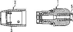
图2A是展示构成该医疗用连接系统的阳型连接器(male typeconnector)的立体图,图2B是主视图,图2C是剖视图。2A is a perspective view showing a male type connector constituting the medical connection system, FIG. 2B is a front view, and FIG. 2C is a cross-sectional view.
图3A是展示构成该医疗用连接系统的保护罩的剖视图。Fig. 3A is a sectional view showing a protective cover constituting the medical connection system.
图3B是展示在该保护罩内装填了内部罩的状态的剖视图。Fig. 3B is a cross-sectional view showing a state in which the inner cover is packed in the protective cover.
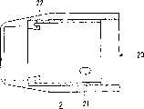
图4A是展示构成该医疗用连接系统的内部罩的立体图,图4B是俯视图,图4C是剖视图。FIG. 4A is a perspective view showing an inner cover constituting the medical connection system, FIG. 4B is a plan view, and FIG. 4C is a cross-sectional view.
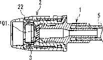
图5A是展示在构成该医疗用连接系统的阳型连接器内安装了内部罩的状态的剖视图,图5B是主视图,图5C是剖视图。5A is a cross-sectional view showing a state in which an inner cover is attached to a male connector constituting the medical connection system, FIG. 5B is a front view, and FIG. 5C is a cross-sectional view.
图6A是展示构成该医疗用连接系统的阴型连接器的剖视图。Fig. 6A is a sectional view showing a female connector constituting the medical connection system.
图6B是展示在该阴型连接器内装填了内部罩的状态的剖视图。Fig. 6B is a cross-sectional view showing a state in which an inner cover is loaded in the female connector.
图7A~7E是用于说明向构成该医疗用连接系统的阳型连接器安装以及脱离保护罩之际的动作的剖视图。7A to 7E are cross-sectional views for explaining the operation when attaching and detaching the protective cover to and from the male connector constituting the medical connection system.
图8A~8E是用于说明将构成该医疗用连接系统的阳型连接器和阴型连接器连接在一起以及连接解除之际的动作的剖视图。8A to 8E are cross-sectional views for explaining operations when the male connector and the female connector constituting the medical connection system are connected together and disconnected.
具体实施方式Detailed ways
根据本发明的医疗用连接系统的上述结构,可以通过内部罩的浸含杀菌剂部件防止阳型连接器前端部分被细菌污染。另外,每次进行保护罩的更换时,内部罩也更换成新的,因此不需要烦杂的操作,就能够实现由新鲜的浸含杀菌剂部件进行的杀菌。According to the above structure of the medical connection system of the present invention, the bacteria-contaminated portion of the front end of the male connector can be prevented by the sterilant-impregnated member of the inner cover. In addition, since the inner cover is also replaced with a new one every time the protective cover is replaced, sterilization by a fresh bactericide-impregnated member can be achieved without troublesome operations.
在本发明的医疗用连接系统中,最好以如下的方式构成,即前述阴型连接器具有内部罩保持部,在解除了前述阳型连接器和前述阴型连接器的连接时,前述内部罩被前述内部罩保持部保持在前述阴型连接器的内部,从而从前述阳型连接器的前端脱离。In the medical connection system of the present invention, it is preferable that the female connector has an inner cover holding portion, and when the connection between the male connector and the female connector is released, the inner The cover is held inside the female connector by the inner cover holding portion so as to be detached from the front end of the male connector.
另外更好的是设为如下的构成,即前述阳型连接器,在前端部具有遮蔽内腔的间隔部件,在将在前端保持了前述内部罩的前述阳型连接器,与前述阴型连接器连接在一起时,前述内筒的内端部,贯通前述内部罩的浸含杀菌剂部件以及前述阳型连接器的间隔部件而开通流路。In addition, it is more preferable to set the structure as follows, that is, the male connector has a spacer member that shields the inner cavity at the front end, and the male connector holding the inner cover at the front end is connected to the female connector. When the connectors are connected together, the inner end of the inner cylinder passes through the sterilant-impregnated member of the inner cover and the spacer member of the male connector to open a flow path.
另外更好的是,前述阳型连接器的外表面,形成有沿着周向延伸的周向阶梯部,从而其前端侧与基端侧相比直径较小,进而形成有包括从前述周向阶梯部向基端侧延伸、并且相对于连接器轴向倾斜的倾斜部的导引槽,前述保护罩,在其开口端部附近的内壁面上形成有导引突起;通过在从前述保护罩的开口部插入前述阳型连接器、并且前述保护罩的前述导引突起与前述阳型连接器的前述导引槽相吻合的状态下,将前述保护罩和前述阳型连接器一面相互挤压一面转动,前述导引突起在前述导引槽内滑动,并且前述阳型连接器受到由前述导引槽的倾斜部的螺纹作用带来的驱动力而被拉入前述保护罩的内部,并且前述内部罩的前述卡合凸部,卡合在前述阳型连接器的卡合凹部内。In addition, it is more preferable that the outer surface of the aforementioned male connector is formed with a circumferential step extending along the circumferential direction, so that the diameter of the front end side is smaller than that of the base end side, and further formed includes a step portion from the aforementioned circumferential direction. The step part extends toward the base end side and is inclined relative to the guide groove of the inclined part in the axial direction of the connector. The aforementioned protective cover has a guide protrusion formed on the inner wall surface near its opening end; In the state where the opening of the male connector is inserted into the male connector, and the guide protrusion of the protective cover matches the guide groove of the male connector, the protective cover and the male connector are pressed against each other. While rotating, the aforementioned guide protrusion slides in the aforementioned guide groove, and the aforementioned male connector is pulled into the inside of the aforementioned protective cover by the driving force brought by the screw action of the inclined portion of the aforementioned guide groove, and the aforementioned The engaging convex portion of the inner cover is engaged in the engaging concave portion of the male connector.
另外更好的是,前述阳型连接器,在其前端部内周面上,具有安装了前述内部罩时与其卡合腿的侧部抵接的阻挡突起,前述阴型连接器的前述外筒,具有形成在其开口端部附近的内壁面上的导引突起、以及包括相对于连接器轴向倾斜的倾斜部的导引阶梯部,前述内部罩,在前述环状部的外周面上具有突起;通过在将保持了前述内部罩的前述阳型连接器从前述阴型连接器的开口部插入、并且前述外筒的前述导引突起与前述阳型连接器的前述导引槽相吻合的状态下,将前述阴型连接器和前述阳型连接器一面相互挤压一面使其转动,前述导引突起在前述导引槽内滑动,并且前述阳型连接器受到由前述导引槽的倾斜部的螺纹作用带来的驱动力而被拉入前述阴型连接器的内部,并且在前述内部罩的前述卡合腿被前述阳型连接器的阻挡突起限制了相对于前述阳型连接器的转动的状态下,前述环状部的突起在前述阴型连接器的导引阶梯部的倾斜部滑动,并且从前述阳型连接器离开的方向的轴向的力作用于前述内部罩,从而解除前述内部罩和前述阳型连接器的卡合,进而,前述内部罩,成为被前述外筒的内部罩保持部保持的状态。In addition, it is more preferable that the aforementioned male connector has a blocking protrusion on the inner peripheral surface of its front end that abuts against the side of its engaging leg when the aforementioned inner cover is installed, and the aforementioned outer cylinder of the aforementioned female connector, The inner cover has a guide protrusion formed on the inner wall surface near the opening end thereof, and a guide step portion including an inclined portion inclined relative to the axial direction of the connector, and the inner cover has a protrusion on the outer peripheral surface of the annular portion. ; by inserting the male connector holding the inner cover from the opening of the female connector, and the guide protrusion of the outer cylinder fitting into the guide groove of the male connector Next, the aforementioned female connector and the aforementioned male connector are pressed against each other while being rotated, the aforementioned guide protrusion slides in the aforementioned guide groove, and the aforementioned male connector is received by the inclined portion of the aforementioned guide groove. The driving force brought by the thread action of the aforementioned female connector is pulled into the interior of the aforementioned female connector, and the aforementioned engaging leg of the aforementioned inner cover is restricted from rotating relative to the aforementioned male connector by the blocking protrusion of the aforementioned male connector. In the state, the protrusion of the aforementioned annular portion slides on the inclined portion of the guide step portion of the aforementioned female connector, and the axial force in the direction away from the aforementioned male connector acts on the aforementioned inner cover, thereby releasing the aforementioned The engagement between the inner cover and the male connector, and furthermore, the inner cover is held by the inner cover holding portion of the outer cylinder.
另外更好的是,前述阴型连接器的前述内部罩保持部,由与前述导引阶梯部的前述倾斜部的里侧连续地设置的水平阶梯部构成,通过前述内部罩的前述环状部的突起与前述水平阶梯部抵接,阻止前述内部罩向前述外筒的开口侧的轴向的移动,并将其保持在前述阴型连接器内。Still more preferably, the inner cover holding portion of the female connector is constituted by a horizontal stepped portion provided continuously on the inner side of the inclined portion of the guide stepped portion, passing through the annular portion of the inner cover. The protrusion of the contacting portion abuts against the horizontal step portion, prevents the axial movement of the inner cover toward the opening side of the outer cylinder, and holds it in the female connector.
另外更好的是,前述阴型连接器的前述内部罩保持部,通过如下的方式构成,即设定尺寸为前述外筒的内壁的一部分与前述内部罩的环状部外周面相抵接、或者前述内筒的内端部外壁的一部分与前述内部罩的环状部内周面相抵接,前述内部罩由摩擦力保持。Still more preferably, the inner cover holding portion of the female connector is configured in such a way that a part of the inner wall of the outer cylinder abuts against the outer peripheral surface of the annular portion of the inner cover, or A part of the outer wall of the inner end portion of the inner cylinder is in contact with the inner peripheral surface of the annular portion of the inner cover, and the inner cover is held by frictional force.
上述构成的医疗用连接系统所用的保护罩组装体,是具备具有一端被封闭的大致圆筒形状的前述保护罩、和被保持在该保护罩的里部并且将浸含杀菌剂部件保持在环状部的内侧的前述内部罩的保护罩组装体;在前述保护罩的内壁面上形成有保持前述内部罩的内部罩保持部,前述内部罩,具有从前述环状部的周缘部沿着环轴方向延伸的多个卡合腿,在前述卡合腿的前端上形成有向外侧突出的卡合凸部,前述内部罩以将前述卡合腿的前端朝向前述保护罩的开口侧的方式被保持在前述内部罩保持部。The protective cover assembly used in the medical connection system having the above-mentioned structure is provided with the aforementioned protective cover having a substantially cylindrical shape with one end closed, and the inner part of the protective cover and the bactericide-impregnated member held in the ring. The protective cover assembly of the aforementioned inner cover on the inner side of the shaped part; the inner cover holding part for holding the aforementioned inner cover is formed on the inner wall surface of the aforementioned protective cover, and the aforementioned inner cover has a A plurality of engagement legs extending in the axial direction are formed with engagement protrusions protruding outward at the front ends of the engagement legs, and the inner cover is closed so that the front ends of the engagement legs face the opening side of the protective cover. It is held in the aforementioned inner cover holding portion.
以下,参照图1A~1G、图2A~2C、图3A、图3B、图4A~4C、图5A~5C、图6A、6B具体地说明本发明的实施方式的医疗用连接系统的构成。本实施方式,将腹膜透析的管子连接用的连接器作为一个适用例来说明。Hereinafter, the configuration of the medical connection system according to the embodiment of the present invention will be specifically described with reference to FIGS. 1A to 1G , FIGS. In this embodiment, a connector for connecting a peritoneal dialysis tube will be described as an application example.
如图1A中分解的状态所示,该医疗用连接系统,由阳型连接器1、保护罩2、内部罩3、以及阴型连接器4构成。阳型连接器1,例如,连接在与埋植在患者的腹腔内的腹膜导管相连的延长管5的前端上。阴型连接器4,是连接在例如双联系统(twin bag)、BF、APD等腹膜透析装置的回路前端的连接器,被连接在作为腹膜透析装置的回路前端的延长管5上。内部罩3,如图1B的右侧所示,最初在保持在保护罩2的内部的状态下被提供。内部罩3,如后述,具备浸含杀菌剂部件,例如浸含了杀菌剂的杀菌用海绵。以下,参照图1B~1G说明该医疗用连接系统的各元件的功能的概要。As shown in an exploded state in FIG. 1A , this medical connection system is composed of a
保护罩2,在阳型连接器1和阴型连接器4没有连接在一起时安装在阳型连接器1上,保护连接器前端。为此,如图1B所示,使保持内部罩3的保护罩2与阳型连接器1相对置,然后如图1C所示那样安装。在该状态下,设在内部罩3内的浸含杀菌剂部件包围阳型连接器1的前端部,起到杀菌作用。The
在将阳型连接器1和阴型连接器4连接在一起时,首先,使保护罩2从阳型连接器1脱离并除去。随着该脱离操作,内部罩3,如图1D所示,从保护罩2移动到阳型连接器1。阴型连接器4,如图1E所示那样使其与阳型连接器1相对置,并如图1F所示那样将其与阳型连接器1连接在一起,形成流路。如图1G所示,在解除阳型连接器1和阴型连接器4的连接时,随着后述的操作,内部罩3最终移动到阴型连接器4内,和阴型连接器4一同被废弃。When connecting the
以下,详细地说明以上的各构成要件。首先,参照图2A~图2C对阳型连接器1进行说明。图2A是阳型连接器1的立体图,图2B是主视图,图2C是剖视图。Hereinafter, each of the above constituent elements will be described in detail. First, the
阳型连接器1的本体是树脂制,并且大致呈圆筒状,包括前端部10、中央的导引部11、和后端侧的基端部12。如图2C所示,形成有贯通前端部10、导引部11以及基端部12的内腔。再者,在图2B、图2C中,相对于图2A的状态,在将阳型连接器1绕着本体的轴旋转了90°的状态下进行展示。The body of the
在前端部10上,安装有遮蔽从而保护由内腔形成的流路,并用于确保液密的间隔部件,例如橡胶制隔膜(有细缝)13。再者,隔膜13,虽然在确保与阴型连接器4的结合状态下的液密上是有效的,但不是必需的,也可以用其他的方法确保液密。在导引部11和基端部12的边界部,形成有环状槽14以及凸缘15,在环状槽14上安装有O形圈14a(图2A中未图示)。A spacer member, such as a rubber diaphragm (with slits) 13 , is attached to the
在前端部10上,形成有凹部101,用于收容内部罩3。在前端部10的侧壁上,设有一对卡合孔102。该卡合孔102用于卡止内部罩3。在后面对此进行叙述。与各卡合孔102相邻地形成有阻挡突起103。On the
在导引部11的外周面上,形成有导引槽111。导引槽111,与本体的轴对称地设置一对,在图2A中,一方位于背侧。导引槽111不一定需要一对,即便只有一根在功能上也足够。导引槽111,具有沿着本体的轴向延伸的轴向部111a、倾斜的倾斜部111b、以及沿着周向延伸的周向部111c。在周向部111c上,形成有分离导引槽111的终端部111e的卡合凸条111d。前端部10的外径,比导引部11小,由此,在前端部10和导引部11的边界的外表面上,形成有沿着周向延伸的环状阶梯部112。导引槽111的轴向部111a的前端,与环状阶梯部112相连。On the outer peripheral surface of the
在基端部12上,形成有连接延长管(图未示)的管状的管连接部121。在管连接部121的外侧形成有保护筒122,在保护筒122的两侧设有捏手123。捏手123,用于在使阳型连接器1转动时把持。On the
如图2C所示,在本实施方式中,基端部12,与前端部10以及导引部11分别形成,其一部分嵌合在导引部11的内腔中。该结构,是构成用于在前端部10内保持隔膜13的结构的。即,在形成在前端部10的内腔内的凸缘状的隔膜保持部104,和基端部12的挤压端124之间,夹持着隔膜13。在隔膜保持部104的内周缘上形成有钩部105,与形成在隔膜13的面上的阶梯部卡合,从而抑制隔膜13的变形。为了便于树脂成形,这样的结构较理想,但也可以采用保持隔膜13的其他的结构。As shown in FIG. 2C , in this embodiment, the
其次,参照图3A、图3B所示的剖视图对保护罩2进行说明。图3A展示了没有装填内部罩的状态,图3B展示了装填了内部罩的状态。保护罩2是树脂制,具有前端封闭的中空的大致圆筒形状。在其开口部20附近的内壁面上,形成有导引突起21。导引突起21对称地设置了一对,但图中只图示了一方。在保护罩2的封闭了的端部侧的内周面上,形成有保持爪22。在该部分上,如图3B所示那样保持着内部罩3。Next, the
在从保护罩2的开口部20插入了阳型连接器1时,导引突起21卡合在阳型连接器1的导引槽111内,通过该卡合,可以得到用于调整保护罩2和阳型连接器1的相互的位置关系的导引作用。在后面对该动作进行叙述。When the
其次,参照图4A~图4C对内部罩3进行说明。图4A是内部罩3的立体图,图4B是主视图,图4C是图4B的A-A剖视图。内部罩3是树脂制,具有环状部30、和2根卡合腿31。在环状部30的外周面上,形成有配置在周向上的一对卡合腿31之间的一对突起32。在突起32的一方侧形成有阶梯部32a。在卡合腿31的前端,形成有向外侧突出的卡合凸部33。Next, the
在环状部30的内部,安装有杀菌用海绵34(只在图4B、4C中图示,在图4A中省略图示)。杀菌用海绵34,以遮蔽环状部30的开口部30a的方式配置,例如,通过超声波焊接固定在环状部30的凸缘30b上。在杀菌用海绵34上,设有后述的阴型连接器4的内端部41b可以贯通的一字或十字的细缝(图未示),作为杀菌剂,例如浸含聚乙烯吡咯烷酮碘(povidone iodine)。Inside the
如上述,内部罩3,如图3B所示,最初收容在保护罩2内。由保持爪22夹持内部罩3的环状部30,并通过摩擦卡合来支撑。在将保护罩2安装到阳型连接器1上时,随着相互的转动,卡合腿31的卡合凸部33,在阳型连接器1的前端部10的内周面上滑动。这时,必须以由保护罩2的保持爪22实现的内部罩3的保持,不会被卡合凸部33在前端部10的内周面上滑动时的摩擦力解除的方式,设定保持力。理想的是,与由内部罩3的突起32形成的阶梯部32a抵接,而在保护罩2内设置阻止内部罩3的转动的转动阻止部。As described above, the
在图5A~5C中展示了将内部罩3保持在阳型连接器1的前端部10的状态。在将保护罩2安装在阳型连接器1上的状态下,内部罩3的卡合腿31的卡合凸部33卡合在阳型连接器1的前端部10的卡合孔102内。由此,便可以将内部罩3保持在前端部10内。卡合孔102,不一定是贯通孔,只要在内部罩3的卡合凸部33可以卡合的范围内形成下陷即可。5A to 5C show a state where the
如上述,内部罩3,利用与保护罩2的保持爪22的摩擦卡合被保持在保护罩2内。另外,通过阳型连接器1的卡合孔102和内部罩3的卡合凸部33的卡合,将内部罩3保持在阳型连接器1内。利用阳型连接器1的卡合孔102保持内部罩3的力,以大于利用保护罩2的保持爪22保持内部罩3的力的方式设定。As described above, the
其次,参照图6A以及图6B所示的剖视图对阴型连接器4进行说明。图6A展示了没有装填内部罩的状态,图6B展示了装填了内部罩的状态。Next, the
阴型连接器4,具有由树脂制的外筒40和内筒41构成的双重筒的形状,在外筒40的一端部固定有内筒41。外筒40,在与固定内筒41的一侧相反一侧上具有开口部42,构成作为阴型连接器4的前端部。内筒41,由露出到外筒40的外侧的外端部41a,和位于外筒40的内侧的内端部41b构成。外端部41a,可以与例如作为腹膜透析装置的回路前端的管子相连接。外端部41a的外侧,被外筒40的一端部伸出的保护筒40a包围。虽然在图6A、6B中没有图示,但在保护筒40a的外周面的两侧,形成有与阳型连接器1的捏手123同样的捏手。内端部41b,在将阴型连接器4和阳型连接器1连接在一起时,一面扩张安装在阳型连接器1的前端上的内部罩3的杀菌用海绵34、以及保持在前端部10上的橡胶制隔膜13的细缝,一面贯通,然后到达阳型连接器1的内部,开通流路。The
在外筒40的开口部42附近的内壁上,形成有导引突起43。该导引突起43,具有与形成在保护罩2上的导引突起21同样的形状以及功能。在外筒40的里部的内壁上,形成有导引阶梯部44。导引阶梯部44,由相对于外筒40的轴向倾斜的倾斜部44a,和与轴向正交的水平阶梯部44b构成。水平阶梯部44b,作为用于将内部罩3保持在外筒40的里部的装置起作用。即,当将内部罩3推入外筒40的内部时,如果突起32是与水平阶梯部44b抵接的状态,就保持该状态。在后面对这时的动作进行说明。A
作为内部罩3的保持机构,可以采用外筒40的里部内壁的一部分与内部罩3的环状部30的外周面抵接,并利用摩擦力保持内部罩3的构成。或者,还可以用通过内筒41的外周面和内部罩3的凸缘30b的内周面的抵接,用摩擦力保持内部罩3的方式构成。As the holding mechanism of the
再者,在图6A、6B中,展示了将导引突起43以及导引阶梯部44,形成在与外筒40的壁材不同的部件上的状态。为了便于树脂成形,设为这样的结构较理想,但也可以一体地形成在外筒40的壁材上。另外,最好以如下的方式构成,即在使用前,在阴型连接器4的外筒40的前端部,设有可以破断的薄膜(图未示),保护阴型连接器4的内筒以及流路直到即将使用之前。In addition, in FIG. 6A, 6B, the state which formed the
其次,对具有以上的结构的医疗用连接系统的动作进行说明。Next, the operation of the medical connection system having the above configuration will be described.
首先,参照图7A~7E,说明相对于阳型连接器1安装保护罩2,进而使其脱离时的动作。但是,关于阳型连接器1、保护罩2以及内部罩3的结构的细节,参照图2A~2C、图3A、3B、图4A~4C。First, the operation when the
在图7A~7D中,图示了在固定了保护罩2的状态下,使阳型连接器1转动的情况的、转动途中的各角度位置上的状态。图7A中的阳型连接器1,位于图2A的角度位置。通过从该状态,从其基端侧看使阳型连接器1向右转动90度,到达图7D。另外,在图7E中,展示了从图7D的状态,使保护罩2转动90度的状态。In FIGS. 7A to 7D , when the
首先如图7A所示,使收容有内部罩3的保护罩2与阳型连接器1相对置,然后如图7B所示将阳型连接器1插入保护罩2内。随之,形成在保护罩2的内壁面上的导引突起21,与阳型连接器1的外周面的环状阶梯部112抵接(参照图2A~2C、图3A、3B、图4A~4C)。First, as shown in FIG. 7A , the
其次如果相对于保护罩2转动阳型连接器1,导引突起21在环状阶梯部112内滑动后,与导引槽111的轴向部111a的位置相吻合。由此,成为可以将阳型连接器1相对于保护罩2进一步插入的状态。从该位置开始,如图7C所示,一面挤压阳型连接器1一面使其向右转动。由此,导引突起21沿着导引槽111的倾斜部111b滑动。由此,利用经由导引突起21和导引槽111的卡合的螺丝的作用,将阳型连接器1拉入保护罩2的最里部。通过进一步使其转动,导引突起21进入周向部111c,并进一步超过卡合凸条111d而到达终端部111e。其结果,通过导引突起21和终端部111e的卡合,保护罩2和阳型连接器1,结合成沿着轴向彼此不能拉开的状态。Secondly, if the
在该过程中,内部罩3的卡合腿31进入阳型连接器1的前端部10的凹部101内。由于内部罩3被保护罩2的保持爪22所保持,因此卡合腿31的卡合凸部33在阳型连接器1的前端部10的内周面上滑动。最后,如图7D所示,卡合凸部33与阳型连接器1的卡合孔102卡合,连接完成。在该状态下,由保持在内部罩3内的杀菌用海绵34,将阳型连接器1的前端部杀菌。另外,通过保护罩2的开放端的内周面和O形圈14a抵接,保持保护罩2内部的液密,并保护阳型连接器1的前端使其不接触外气。During this process, the
其次,当从图7D的状态,使保护罩2相对于阳型连接器1向连接时的逆向转动时,内部罩3,利用卡合凸部33和阳型连接器1的卡合孔102卡合的情况,与阳型连接器1一起相对于保护罩2转动。随着转动,保护罩2的导引突起21在导引槽111内滑动,并到达轴向部111a。从该状态将阳型连接器1和保护罩2沿着轴向拉开时,内部罩3在安装在阳型连接器1前端的状态下被从保护罩2内取下,成为图7E所示的状态。Next, when the
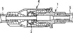
其次参照图8A~8E,说明将阳型连接器1和阴型连接器4连接在一起时的动作。但是,关于阳型连接器1、内部罩3、以及阴型连接器4的结构的细节,参照图2A~2C、图4A~4C、以及图6A、6B。Next, referring to FIGS. 8A to 8E , the operation of connecting the
在图8A~8D中,图示了在用与图7E同样的角度固定了阳型连接器1的状态下,使阴型连接器4转动时的、转动途中的各角度位置上的状态。图8A中的阴型连接器4,用图6A、6B的角度展示,从内端部41b的一侧看,通过使其向右转动90度,到达图8D的状态。在图8E中,展示了从图8D的状态使阳型连接器1,从管连接部121的一侧看向左转动90度的状态。FIGS. 8A to 8D show the states at various angular positions in the middle of the rotation when the
首先如图8A所示,使阳型连接器1和阴型连接器4相对置,在该状态下,在阳型连接器1的前端安装有内部罩3。其次如图8B所示,将阳型连接器1插入阴型连接器4的外筒40内。这时,形成在阴型连接器4的内壁面上的导引突起43,与阳型连接器1外周面的环状阶梯部112抵接。如果使阴型连接器4适当地转动而使导引突起43与阳型连接器1的导引槽111的轴向部111a相吻合,便成为可以将阳型连接器1相对于阴型连接器4进一步插入的状态。再者,由于内部罩3的卡合腿31卡合在阳型连接器1的前端部10的凹部101内,因此不会从阳型连接器1的外周面突出。因而,在将阳型连接器1插入阴型连接器4的外筒40内时与外筒40的内壁面的干涉少,可以顺利地进行插入或转动的操作。First, as shown in FIG. 8A , the
为了进一步将阳型连接器1插入里部,一面挤压阳型连接器1,一面使阴型连接器4向右转动。随之,导引突起43沿着导引槽111的倾斜部111b滑动。由此,导引突起43和导引槽111产生螺纹作用(screwaction),阳型连接器1,如图8C所示,到达阴型连接器4的最里部。在该状态下,安装在阳型连接器1的前端部的内部罩3的突起32,相对于图6A所示的导引阶梯部44的倾斜部44a,位于周向的右侧。In order to further insert the
通过进一步使其转动,导引突起43进入周向部111c,在导引突起43在周向部111c内滑动的过程中,设在内部罩3的环状部30上的突起32与倾斜部44a抵接。利用经由卡合腿31的侧面和阳型连接器1的阻挡突起103的抵接而被付与的转动力,突起32在倾斜部44a上滑动。由此,内部罩3,从倾斜部44a受到向阴型连接器4的里部的轴向的力。其结果,如图8D所示,形成在内部罩3的卡合腿31上的卡合凸部33、和阳型连接器1的卡合孔102的卡合被解开。最终内部罩3的突起32,到达阴型连接器4的导引阶梯部44的水平阶梯部44b。在该状态下,内部罩3被保持在阴型连接器4内。即,即便为了解除阳型连接器1和阴型连接器4的连接,而如后述那样使阳型连接器1向左转动,由于卡合孔102和卡合凸部33的卡合被解开,因此内部罩3不会转动。并且,由于内部罩3的突起32和水平阶梯部44b卡合在一起,因此内部罩3也不会向从阴型连接器4脱离的方向产生轴向的移动。By further turning, the
另外,如上述,阴型连接器4的内筒41的内端部41b,在将阴型连接器4和阳型连接器1连接在一起的过程中,一面将内部罩3的杀菌用海绵32、以及保持在阳型连接器1的前端部10上的隔膜13的细缝扩张、一面贯通,从而到达阳型连接器1的内部并开通流路。这时,阴型连接器4的内筒41,被杀菌用海绵32杀菌。In addition, as mentioned above, the
在解除阴型连接器4和阳型连接器1的连接时,使阳型连接器1向左转动。由此,导引突起43和导引槽111的卡合被解开,可以将两个连接器沿着轴向拉开。这时如上述,内部罩3被留置在阴型连接器4内(图8E)。When the connection between the
之后,如果将新的保护罩2安装到阳型连接器1上,便可以将新的内部罩3安装到阳型连接器1的前端,如上述,可以维持对于阳型连接器1的前端部的杀菌作用。Afterwards, if a new
工业上的可利用性Industrial availability
根据本发明的医疗用连接系统,通过内部罩的含浸杀菌剂部件,避免阳型连接器前端部分的污染,另外,在每次进行保护罩的更换时,内部罩被更换成新的,不需要烦杂的操作,就能够适时地实现由新鲜的含浸杀菌剂部件进行的杀菌,因此作为用于腹膜透析、输液用等的流路连接的连接器很适用。According to the medical connection system of the present invention, the contamination of the front end portion of the male connector is avoided by the sterilant-impregnated part of the inner cover. In addition, when the protective cover is replaced each time, the inner cover is replaced with a new one, which does not require It is possible to realize timely sterilization by a fresh sterilant-impregnated member without troublesome operation, so it is suitable as a connector for peritoneal dialysis, infusion, etc. for connecting fluid channels.
Claims (8)
Applications Claiming Priority (3)
| Application Number | Priority Date | Filing Date | Title |
|---|---|---|---|
| JP284160/2003 | 2003-07-31 | ||
| JP2003284160 | 2003-07-31 | ||
| PCT/JP2004/011114WO2005011798A1 (en) | 2003-07-31 | 2004-07-28 | Connector system for medical use |
Publications (2)
| Publication Number | Publication Date |
|---|---|
| CN1829551Atrue CN1829551A (en) | 2006-09-06 |
| CN1829551B CN1829551B (en) | 2011-06-08 |
Family
ID=34113832
Family Applications (1)
| Application Number | Title | Priority Date | Filing Date |
|---|---|---|---|
| CN2004800219367AExpired - Fee RelatedCN1829551B (en) | 2003-07-31 | 2004-07-28 | Connection system for medical use |
Country Status (7)
| Country | Link |
|---|---|
| US (1) | US7452349B2 (en) |
| EP (1) | EP1649890B1 (en) |
| JP (1) | JP4196994B2 (en) |
| KR (2) | KR100940701B1 (en) |
| CN (1) | CN1829551B (en) |
| CA (1) | CA2534311C (en) |
| WO (1) | WO2005011798A1 (en) |
Cited By (17)
| Publication number | Priority date | Publication date | Assignee | Title |
|---|---|---|---|---|
| CN102170978A (en)* | 2008-10-02 | 2011-08-31 | 巴德阿克塞斯系统股份有限公司 | Site scrub brush |
| CN102458506A (en)* | 2009-04-23 | 2012-05-16 | 费森尼斯医疗德国公司 | Connection device and method for connecting at least two fluid conveying medical technology systems, and medical technology device |
| CN102553068A (en)* | 2010-09-30 | 2012-07-11 | 泰科保健集团有限合伙公司 | Antimicrobial Luer |
| CN102573984A (en)* | 2009-07-28 | 2012-07-11 | 汉斯-于尔根·霍普夫 | Connection systems for fluid connections in medicine |
| CN102802692A (en)* | 2009-06-12 | 2012-11-28 | 株式会社Jms | Medical fluid communication device |
| CN101677905B (en)* | 2007-06-08 | 2013-05-08 | 株式会社Jms | Female connectors and connection tools |
| CN103260696A (en)* | 2010-10-20 | 2013-08-21 | 弗雷泽纽斯卡比德国有限公司 | Protective Covers for Connectors |
| US8671496B2 (en) | 2007-04-02 | 2014-03-18 | C.R. Bard, Inc. | Insert for a microbial scrubbing device |
| US8696820B2 (en) | 2008-03-31 | 2014-04-15 | Bard Access Systems, Inc. | Method of removing a biofilm from a surface |
| CN104703638A (en)* | 2012-10-09 | 2015-06-10 | 东丽株式会社 | Plug, medical module and medical system |
| US9192449B2 (en) | 2007-04-02 | 2015-11-24 | C. R. Bard, Inc. | Medical component scrubbing device with detachable cap |
| CN109893695A (en)* | 2017-12-11 | 2019-06-18 | 泰尔茂株式会社 | Cap |
| CN110124147A (en)* | 2019-05-17 | 2019-08-16 | 深圳安特医疗股份有限公司 | Protective cap |
| CN110639076A (en)* | 2013-11-06 | 2020-01-03 | 弗雷泽纽斯医疗保健德国有限公司 | First and second connection parts |
| CN111867669A (en)* | 2018-01-17 | 2020-10-30 | 赛特萨弗股份有限公司 | Separate medical tube connectors |
| CN112188913A (en)* | 2018-04-10 | 2021-01-05 | 贝克顿·迪金森公司 | Universal disposable cap for male and female connectors |
| CN117861064A (en)* | 2024-03-13 | 2024-04-12 | 苏州同心医疗科技股份有限公司 | Anti-disengaging mechanism for artificial heart connector and protective cover |
Families Citing this family (98)
| Publication number | Priority date | Publication date | Assignee | Title |
|---|---|---|---|---|
| GB2424836B (en)* | 2005-04-06 | 2010-09-22 | Cilag Ag Int | Injection device (bayonet cap removal) |
| US7611505B2 (en)* | 2005-05-10 | 2009-11-03 | Baxa Corporation | Sterile docking apparatus and method |
| US8740864B2 (en) | 2005-11-17 | 2014-06-03 | Becton, Dickinson And Company | Patient fluid line access valve antimicrobial cap/cleaner |
| US8321008B2 (en)* | 2005-11-30 | 2012-11-27 | Nitric Biotherapeutics, Inc. | Combination cartridge and device for electrokinetic delivery of medicament to a treatment site |
| US9895526B2 (en) | 2006-03-08 | 2018-02-20 | Ivaxis, Llc | Anti-contamination cover for fluid connections |
| JP5087858B2 (en)* | 2006-04-28 | 2012-12-05 | ニプロ株式会社 | Mixed injection connector |
| US9592375B2 (en) | 2006-05-18 | 2017-03-14 | Hyprotek, Inc. | Intravascular line and port cleaning methods, methods of administering an agent intravascularly, methods of obtaining/testing blood, and devices for performing such methods |
| US8162899B2 (en) | 2006-05-18 | 2012-04-24 | Hyprotek, Inc. | Intravascular line and port cleaning methods, methods of administering an agent intravascularly, methods of obtaining/testing blood, and devices for performing such methods |
| US9700710B2 (en) | 2006-06-22 | 2017-07-11 | Excelsior Medical Corporation | Antiseptic cap equipped syringe |
| US9259535B2 (en) | 2006-06-22 | 2016-02-16 | Excelsior Medical Corporation | Antiseptic cap equipped syringe |
| US11229746B2 (en) | 2006-06-22 | 2022-01-25 | Excelsior Medical Corporation | Antiseptic cap |
| US8167847B2 (en) | 2006-06-22 | 2012-05-01 | Excelsior Medical Corporation | Antiseptic cap and antiseptic cap equipped plunger and syringe barrel assembly |
| ATE485075T1 (en)* | 2006-07-07 | 2010-11-15 | Caridianbct Inc | METHOD FOR CONNECTING THERMOPLASTIC HOSES |
| US7780794B2 (en) | 2006-07-21 | 2010-08-24 | Ivera Medical Corporation | Medical implement cleaning device |
| US8257286B2 (en) | 2006-09-21 | 2012-09-04 | Tyco Healthcare Group Lp | Safety connector apparatus |
| WO2008070220A1 (en)* | 2006-12-05 | 2008-06-12 | Caridianbct, Inc. | Connector system for sterile connection |
| AU2008206312A1 (en)* | 2007-01-16 | 2008-07-24 | University Of Utah Research Foundation | Nestable sterility-protecting caps for separated connectors |
| US9259284B2 (en) | 2007-02-12 | 2016-02-16 | 3M Innovative Properties Company | Female Luer connector disinfecting cap |
| US8065773B2 (en)* | 2007-04-02 | 2011-11-29 | Bard Access Systems, Inc. | Microbial scrub brush |
| US20080262414A1 (en)* | 2007-04-20 | 2008-10-23 | Transport Pharmaceuticals, Inc. | Single use applicator cartridge for an electrokinetic delivery system and method for self administration of medicaments |
| US8287513B2 (en)* | 2007-09-11 | 2012-10-16 | Carmel Pharma Ab | Piercing member protection device |
| CA2644187A1 (en)* | 2007-12-05 | 2009-06-05 | Tyco Healthcare Group Lp | Device for reducing microbial contamination |
| US8257287B2 (en) | 2008-03-20 | 2012-09-04 | Tyco Healthcare Group Lp | Safety connector assembly |
| EP2303339B1 (en)* | 2008-06-17 | 2014-07-16 | Gambro Lundia AB | Maintaining sterile conditions in a fluid transportation system |
| US7762524B2 (en)* | 2008-10-20 | 2010-07-27 | Baxter International Inc. | Barrier assembly for use with needleless connector |
| US9078992B2 (en) | 2008-10-27 | 2015-07-14 | Pursuit Vascular, Inc. | Medical device for applying antimicrobial to proximal end of catheter |
| EP2413978B1 (en) | 2009-04-01 | 2014-07-09 | C.R. Bard, Inc. | Microbial scrubbing device |
| US9480833B2 (en) | 2010-07-15 | 2016-11-01 | Becton, Dickinson And Company | Antimicrobial IV access cap |
| US8721627B2 (en)* | 2010-07-22 | 2014-05-13 | Carefusion 303, Inc. | Needleless valve infection prevention and pre-opening device |
| US10166365B2 (en)* | 2010-09-30 | 2019-01-01 | Covidien Lp | Catheter assembly including sealing member |
| WO2012162259A2 (en) | 2011-05-20 | 2012-11-29 | Excelsior Medical Corporation | Caps for cannula access devices |
| US9867975B2 (en) | 2011-05-23 | 2018-01-16 | Excelsior Medical Corporation | Antiseptic line cap |
| US10166381B2 (en) | 2011-05-23 | 2019-01-01 | Excelsior Medical Corporation | Antiseptic cap |
| EP2723281A4 (en)* | 2011-06-27 | 2014-12-24 | Insleep Technologies Llc | Replaceable nasal interface system |
| WO2013009998A2 (en) | 2011-07-12 | 2013-01-17 | Pursuit Vascular, Inc. | Device for delivery of antimicrobial agent into trans-dermal catheter |
| US8784388B2 (en) | 2011-09-30 | 2014-07-22 | Becton, Dickinson And Company | Syringe with disinfecting tip feature |
| US10828402B2 (en)* | 2011-10-14 | 2020-11-10 | Alcon Inc. | Collar connector |
| RU2623490C2 (en) | 2011-10-19 | 2017-06-26 | БАЙЕР ХелсКер ЛЛСи | Sterile maintaining medical connector unit and method |
| ES2676825T3 (en) | 2012-02-15 | 2018-07-25 | Np Medical Inc. | Multipurpose protective cover for use in a medical device |
| US9999471B2 (en) | 2012-06-04 | 2018-06-19 | 3M Innovative Properties Company | Male medical implement cleaning device |
| US9302049B2 (en) | 2012-08-20 | 2016-04-05 | Becton, Dickinson And Company | Medical devices for blood reflux prevention and methods of use |
| US9677590B2 (en) | 2012-10-16 | 2017-06-13 | Javier E. Oliver | Rotating tension latch |
| US10844894B2 (en) | 2012-10-16 | 2020-11-24 | Javier E. Oliver | Rotating tension latch |
| US9399125B2 (en) | 2013-02-13 | 2016-07-26 | Becton, Dickinson And Company | Needleless connector and access port disinfection cleaner and antimicrobial protection cap |
| US9039989B2 (en)* | 2013-02-13 | 2015-05-26 | Becton, Dickinson And Company | Disinfection cap for disinfecting a male luer end of an infusion therapy device |
| US10143830B2 (en)* | 2013-03-13 | 2018-12-04 | Crisi Medical Systems, Inc. | Injection site information cap |
| US9414990B2 (en) | 2013-03-15 | 2016-08-16 | Becton Dickinson and Company Ltd. | Seal system for cannula |
| US9597260B2 (en) | 2013-03-15 | 2017-03-21 | Becton Dickinson and Company Ltd. | System for closed transfer of fluids |
| US9907617B2 (en) | 2013-03-15 | 2018-03-06 | 3M Innovative Properties Company | Medical implement cleaning device |
| KR20160021194A (en) | 2013-06-14 | 2016-02-24 | 바이엘 메디컬 케어 인크. | Portable fluid delivery system |
| WO2014210418A1 (en)* | 2013-06-28 | 2014-12-31 | Bayer Medical Care Inc. | Sterility retaining medical connector assembly and method |
| EP3035997B1 (en)* | 2013-08-21 | 2018-04-11 | Cedic S.r.l. | Needlefree valve device |
| CA2929476C (en) | 2013-11-06 | 2019-01-22 | Becton Dickinson and Company Limited | System for closed transfer of fluids with a locking member |
| EP3065694B1 (en) | 2013-11-06 | 2020-04-29 | Becton Dickinson and Company Limited | System for closed transfer of fluids having connector |
| ES2780857T3 (en) | 2013-11-06 | 2020-08-27 | Becton Dickinson & Co Ltd | Connection device for a medical device |
| ES2780856T3 (en) | 2013-11-06 | 2020-08-27 | Becton Dickinson & Co Ltd | Medical connector having locking coupling |
| HRP20241397T1 (en) | 2014-01-10 | 2024-12-20 | Bayer Healthcare Llc | CONNECTOR FOR DISPOSABLE KIT |
| US9283369B2 (en) | 2014-02-20 | 2016-03-15 | Becton, Dickinson And Company | IV access port cap for providing antimicrobial protection |
| CN106232082B (en) | 2014-04-16 | 2019-03-12 | 贝克顿迪金森有限公司 | Fluid delivery device with axially and rotatably movable parts |
| EP3398583A1 (en) | 2014-04-21 | 2018-11-07 | Becton Dickinson and Company Limited | System with adapter for closed transfer of fluids |
| BR112016024680B8 (en) | 2014-04-21 | 2021-11-09 | Becton Dickinson & Co Ltd | Syringe adapter |
| CN110353993B (en) | 2014-04-21 | 2022-04-12 | 贝克顿迪金森有限公司 | Bottle stabilizer base with attachable bottle adapter |
| EP3134058B1 (en) | 2014-04-21 | 2020-03-18 | Becton Dickinson and Company Limited | Fluid transfer device and packaging therefor |
| EP3134057B1 (en) | 2014-04-21 | 2018-06-27 | Becton Dickinson and Company Limited | Syringe adapter with compound motion disengagement |
| EP4091597A1 (en) | 2014-04-21 | 2022-11-23 | Becton Dickinson and Company Limited | Syringe adapter with disconnection feedback mechanism |
| AU2015249915B2 (en) | 2014-04-21 | 2017-11-30 | Becton Dickinson and Company Limited | System for closed transfer of fluids |
| ES2792512T3 (en) | 2014-04-21 | 2020-11-11 | Becton Dickinson & Co Ltd | Fluid transfer device and packaging for it |
| EP3137122B1 (en) | 2014-05-02 | 2019-09-04 | Excelsior Medical Corporation | Strip package for antiseptic cap |
| DE102014106442B3 (en)* | 2014-05-08 | 2015-11-05 | Sicos Gmbh | Connecting device for a catheter, in particular a peripheral venous catheter |
| US10195069B2 (en)* | 2014-07-16 | 2019-02-05 | Coloplast A/S | Outlet for a urostomy appliance |
| JP6368603B2 (en)* | 2014-09-25 | 2018-08-01 | テルモ株式会社 | Disinfection cap |
| US10507319B2 (en) | 2015-01-09 | 2019-12-17 | Bayer Healthcare Llc | Multiple fluid delivery system with multi-use disposable set and features thereof |
| CN104548332B (en)* | 2015-01-20 | 2018-04-20 | 雷诺丽特塑料科技(北京)有限公司 | A kind of easy-tear type iodide-containing cap and its manufacture method |
| USD757930S1 (en) | 2015-03-19 | 2016-05-31 | Insleep Technologies, Llc | Nasal pillow |
| USD768287S1 (en) | 2015-04-03 | 2016-10-04 | Insleep Technologies, Llc | Nasal interface base |
| DK3294404T3 (en) | 2015-05-08 | 2025-09-08 | Icu Medical Inc | MEDICAL CONNECTORS CONFIGURED TO RECEIVE EMISSIONS OF THERAPEUTIC AGENTS |
| WO2017048955A1 (en)* | 2015-09-15 | 2017-03-23 | The Regents Of The University Of California | Systems and methods for sterile catheter connection |
| JP6919794B2 (en)* | 2015-12-15 | 2021-08-18 | 株式会社ジェイ・エム・エス | Female connector |
| US20170224974A1 (en)* | 2016-02-09 | 2017-08-10 | Amt Pte Ltd | Medical device adapter with luer lock output fitting |
| TWI651107B (en) | 2016-06-15 | 2019-02-21 | 拜耳保健公司 | Multi-use disposable system and syringe therefor |
| US10610676B2 (en)* | 2016-09-26 | 2020-04-07 | Drma Group International Llc | Disinfecting luer connector |
| PT3525865T (en) | 2016-10-14 | 2022-11-17 | Icu Medical Inc | Sanitizing caps for medical connectors |
| WO2018204206A2 (en) | 2017-05-01 | 2018-11-08 | Icu Medical, Inc. | Medical fluid connectors and methods for providing additives in medical fluid lines |
| US11147957B2 (en) | 2017-07-19 | 2021-10-19 | Becton, Dickinson And Company | Systems and methods to improve instrument guidance within an intravenous catheter assembly |
| WO2019130891A1 (en) | 2017-12-26 | 2019-07-04 | テルモ株式会社 | Medical connector |
| US11097083B2 (en) | 2018-07-17 | 2021-08-24 | Becton, Dickinson And Company | Systems and methods to improve instrument guidance within an intravenous catheter assembly |
| US11517732B2 (en) | 2018-11-07 | 2022-12-06 | Icu Medical, Inc. | Syringe with antimicrobial properties |
| US11534595B2 (en) | 2018-11-07 | 2022-12-27 | Icu Medical, Inc. | Device for delivering an antimicrobial composition into an infusion device |
| US11541220B2 (en) | 2018-11-07 | 2023-01-03 | Icu Medical, Inc. | Needleless connector with antimicrobial properties |
| US11400195B2 (en) | 2018-11-07 | 2022-08-02 | Icu Medical, Inc. | Peritoneal dialysis transfer set with antimicrobial properties |
| US11541221B2 (en) | 2018-11-07 | 2023-01-03 | Icu Medical, Inc. | Tubing set with antimicrobial properties |
| EP3883638A1 (en) | 2018-11-21 | 2021-09-29 | ICU Medical, Inc. | Antimicrobial device comprising a cap with ring and insert |
| MA55036A (en)* | 2019-02-19 | 2021-12-29 | Cleansite Medical Inc | CAPING AND CLEANING DEVICES FOR NEEDLELESS VASCULAR ACCESS CONNECTORS |
| JP2021142226A (en)* | 2020-03-13 | 2021-09-24 | ニプロ株式会社 | Male connector for enteral nutrition |
| JP2023546374A (en) | 2020-10-09 | 2023-11-02 | アイシーユー・メディカル・インコーポレーテッド | Fluid transfer device and method of use therefor |
| CA3204371A1 (en) | 2020-12-07 | 2022-06-16 | Icu Medical, Inc. | Peritoneal dialysis caps, systems and methods |
| CN119969965A (en)* | 2020-12-09 | 2025-05-13 | 健源医疗科技(无锡)有限公司 | A locking mechanism for an optical tomography device |
| JP2025525713A (en)* | 2022-08-02 | 2025-08-07 | バクスター・インターナショナル・インコーポレイテッド | Sterile peritoneal dialysis transfer set |
Family Cites Families (14)
| Publication number | Priority date | Publication date | Assignee | Title |
|---|---|---|---|---|
| US4810241A (en)* | 1980-06-09 | 1989-03-07 | Rogers Phillip P | Ambulatory dialysis system and connector |
| US4511359A (en)* | 1982-09-29 | 1985-04-16 | Manresa, Inc. | Sterile connection device |
| NL8300386A (en)* | 1983-02-02 | 1984-09-03 | Steritech Bv | STERILE DEVICE CONNECTING TWO ROOMS. |
| US4810242A (en) | 1985-09-26 | 1989-03-07 | Alcon Laboratories Inc. | Surgical cassette proximity sensing and latching apparatus |
| IT1201907B (en)* | 1986-11-05 | 1989-02-02 | Frau Spa | CENTRIFUGAL SEPARATOR OF LIQUIDS WITH ROTATING SEALS ON THE FIXED UPPER HEAD |
| JP3058205B2 (en) | 1991-08-02 | 2000-07-04 | テルモ株式会社 | Medical coupler and cap device |
| JP3228373B2 (en) | 1993-04-28 | 2001-11-12 | ニプロ株式会社 | Lure connector device |
| US5533996A (en)* | 1994-08-24 | 1996-07-09 | Baxter International, Inc. | Transfer set connector with permanent, integral cam opening closure and a method of using the same |
| CN2205213Y (en)* | 1994-09-21 | 1995-08-16 | 湖南医科大学附属第二医院 | Concentric circle joint for peritoneal dialysis |
| US5554135A (en)* | 1995-02-17 | 1996-09-10 | Menyhay; Steve Z. | Sterile medical injection port and cover method and apparatus |
| GB9615010D0 (en)* | 1996-07-17 | 1996-09-04 | Peters Joseph L | Couplings for medical cannulae |
| JP2002345952A (en)* | 2001-05-30 | 2002-12-03 | Shimizu Pharmaceutical Co Ltd | Tube connector for artificial dialysis |
| JP3972665B2 (en)* | 2002-01-25 | 2007-09-05 | 株式会社ジェイ・エム・エス | Aseptic connector system |
| US6911025B2 (en)* | 2002-01-25 | 2005-06-28 | Jms Co., Ltd. | Connector system for sterile connection |
- 2004
- 2004-07-28EPEP04771165Apatent/EP1649890B1/ennot_activeExpired - Lifetime
- 2004-07-28USUS10/565,953patent/US7452349B2/ennot_activeExpired - Fee Related
- 2004-07-28CNCN2004800219367Apatent/CN1829551B/ennot_activeExpired - Fee Related
- 2004-07-28KRKR1020087009843Apatent/KR100940701B1/ennot_activeExpired - Fee Related
- 2004-07-28JPJP2005512556Apatent/JP4196994B2/ennot_activeExpired - Lifetime
- 2004-07-28WOPCT/JP2004/011114patent/WO2005011798A1/enactiveApplication Filing
- 2004-07-28CACA002534311Apatent/CA2534311C/ennot_activeExpired - Fee Related
- 2004-07-28KRKR1020067002183Apatent/KR100872259B1/ennot_activeExpired - Fee Related
Cited By (27)
| Publication number | Priority date | Publication date | Assignee | Title |
|---|---|---|---|---|
| US9186707B2 (en) | 2007-04-02 | 2015-11-17 | C. R. Bard, Inc. | Insert for a microbial scrubbing device |
| US9352140B2 (en) | 2007-04-02 | 2016-05-31 | C. R. Bard, Inc. | Medical component scrubbing device with detachable cap |
| US8671496B2 (en) | 2007-04-02 | 2014-03-18 | C.R. Bard, Inc. | Insert for a microbial scrubbing device |
| US9192449B2 (en) | 2007-04-02 | 2015-11-24 | C. R. Bard, Inc. | Medical component scrubbing device with detachable cap |
| CN101677905B (en)* | 2007-06-08 | 2013-05-08 | 株式会社Jms | Female connectors and connection tools |
| US8696820B2 (en) | 2008-03-31 | 2014-04-15 | Bard Access Systems, Inc. | Method of removing a biofilm from a surface |
| CN102170978A (en)* | 2008-10-02 | 2011-08-31 | 巴德阿克塞斯系统股份有限公司 | Site scrub brush |
| CN106247052B (en)* | 2009-04-23 | 2019-09-17 | 费森尼斯医疗德国公司 | Medical equipment |
| CN102458506B (en)* | 2009-04-23 | 2016-08-24 | 费森尼斯医疗德国公司 | Connection device and method for connecting at least two fluid conveying medical technology systems, and medical technology device |
| CN102458506A (en)* | 2009-04-23 | 2012-05-16 | 费森尼斯医疗德国公司 | Connection device and method for connecting at least two fluid conveying medical technology systems, and medical technology device |
| CN106247052A (en)* | 2009-04-23 | 2016-12-21 | 费森尼斯医疗德国公司 | In order to connect attachment means and the method for at least two fluid conveying medical-technical system, and medical equipment |
| CN102802692A (en)* | 2009-06-12 | 2012-11-28 | 株式会社Jms | Medical fluid communication device |
| CN102802692B (en)* | 2009-06-12 | 2015-04-01 | 株式会社Jms | Medical fluid communication device |
| CN102573984A (en)* | 2009-07-28 | 2012-07-11 | 汉斯-于尔根·霍普夫 | Connection systems for fluid connections in medicine |
| CN102553068B (en)* | 2010-09-30 | 2014-01-22 | 泰科保健集团有限合伙公司 | Antimicrobial Luer |
| CN102553068A (en)* | 2010-09-30 | 2012-07-11 | 泰科保健集团有限合伙公司 | Antimicrobial Luer |
| CN103260696A (en)* | 2010-10-20 | 2013-08-21 | 弗雷泽纽斯卡比德国有限公司 | Protective Covers for Connectors |
| CN104703638A (en)* | 2012-10-09 | 2015-06-10 | 东丽株式会社 | Plug, medical module and medical system |
| CN110639076A (en)* | 2013-11-06 | 2020-01-03 | 弗雷泽纽斯医疗保健德国有限公司 | First and second connection parts |
| CN110639076B (en)* | 2013-11-06 | 2023-07-04 | 弗雷泽纽斯医疗保健德国有限公司 | First and second connecting parts |
| CN109893695A (en)* | 2017-12-11 | 2019-06-18 | 泰尔茂株式会社 | Cap |
| CN111867669A (en)* | 2018-01-17 | 2020-10-30 | 赛特萨弗股份有限公司 | Separate medical tube connectors |
| CN112188913A (en)* | 2018-04-10 | 2021-01-05 | 贝克顿·迪金森公司 | Universal disposable cap for male and female connectors |
| CN112188913B (en)* | 2018-04-10 | 2022-11-15 | 贝克顿·迪金森公司 | Universal disposable caps for male and female connectors |
| CN110124147A (en)* | 2019-05-17 | 2019-08-16 | 深圳安特医疗股份有限公司 | Protective cap |
| CN110124147B (en)* | 2019-05-17 | 2022-05-03 | 深圳安特医疗股份有限公司 | Protective cap and method for sterilizing infusion tube by using protective cap |
| CN117861064A (en)* | 2024-03-13 | 2024-04-12 | 苏州同心医疗科技股份有限公司 | Anti-disengaging mechanism for artificial heart connector and protective cover |
Also Published As
| Publication number | Publication date |
|---|---|
| EP1649890A1 (en) | 2006-04-26 |
| CN1829551B (en) | 2011-06-08 |
| JPWO2005011798A1 (en) | 2006-09-14 |
| KR100872259B1 (en) | 2008-12-05 |
| JP4196994B2 (en) | 2008-12-17 |
| CA2534311C (en) | 2008-12-30 |
| EP1649890A4 (en) | 2006-10-25 |
| HK1091425A1 (en) | 2007-01-19 |
| KR20060034720A (en) | 2006-04-24 |
| KR100940701B1 (en) | 2010-02-08 |
| US7452349B2 (en) | 2008-11-18 |
| WO2005011798A1 (en) | 2005-02-10 |
| CA2534311A1 (en) | 2005-02-10 |
| US20060189961A1 (en) | 2006-08-24 |
| EP1649890B1 (en) | 2011-05-18 |
| KR20080052680A (en) | 2008-06-11 |
Similar Documents
| Publication | Publication Date | Title |
|---|---|---|
| CN1829551A (en) | Connection system for medical use | |
| US6911025B2 (en) | Connector system for sterile connection | |
| US7083605B2 (en) | Connector system for sterile connection | |
| US7708714B2 (en) | Dialysis connector with retention and feedback features | |
| US8986243B2 (en) | Peritoneal dialysis patient connection system | |
| JP7697967B2 (en) | Caps for male and female threaded joints | |
| CN1352569A (en) | Needle-less luer activated medical connector | |
| JP7677480B2 (en) | Male Connector | |
| CN114340717A (en) | Medical connectors that seal automatically when disconnected | |
| JP7298035B2 (en) | rotary peritoneal dialysis interconnect | |
| HK1091425B (en) | Medical connector system | |
| US20240066279A1 (en) | Catheter to patient line connection assist device | |
| WO2022214490A1 (en) | Vent device, port assembly and vascular access assembly | |
| HK1057498B (en) | Connector system for sterile connection |
Legal Events
| Date | Code | Title | Description |
|---|---|---|---|
| C06 | Publication | ||
| PB01 | Publication | ||
| C10 | Entry into substantive examination | ||
| SE01 | Entry into force of request for substantive examination | ||
| REG | Reference to a national code | Ref country code:HK Ref legal event code:DE Ref document number:1091425 Country of ref document:HK | |
| C14 | Grant of patent or utility model | ||
| GR01 | Patent grant | ||
| REG | Reference to a national code | Ref country code:HK Ref legal event code:GR Ref document number:1091425 Country of ref document:HK | |
| C17 | Cessation of patent right | ||
| CF01 | Termination of patent right due to non-payment of annual fee | Granted publication date:20110608 Termination date:20130728 |