CN1825401A - LED driver - Google Patents
LED driverDownload PDFInfo
- Publication number
- CN1825401A CN1825401ACNA2006100033585ACN200610003358ACN1825401ACN 1825401 ACN1825401 ACN 1825401ACN A2006100033585 ACNA2006100033585 ACN A2006100033585ACN 200610003358 ACN200610003358 ACN 200610003358ACN 1825401 ACN1825401 ACN 1825401A
- Authority
- CN
- China
- Prior art keywords
- switch
- current
- current value
- light
- signal
- Prior art date
- Legal status (The legal status is an assumption and is not a legal conclusion. Google has not performed a legal analysis and makes no representation as to the accuracy of the status listed.)
- Granted
Links
Images


Classifications
- G—PHYSICS
- G09—EDUCATION; CRYPTOGRAPHY; DISPLAY; ADVERTISING; SEALS
- G09G—ARRANGEMENTS OR CIRCUITS FOR CONTROL OF INDICATING DEVICES USING STATIC MEANS TO PRESENT VARIABLE INFORMATION
- G09G3/00—Control arrangements or circuits, of interest only in connection with visual indicators other than cathode-ray tubes
- G09G3/20—Control arrangements or circuits, of interest only in connection with visual indicators other than cathode-ray tubes for presentation of an assembly of a number of characters, e.g. a page, by composing the assembly by combination of individual elements arranged in a matrix no fixed position being assigned to or needed to be assigned to the individual characters or partial characters
- G09G3/22—Control arrangements or circuits, of interest only in connection with visual indicators other than cathode-ray tubes for presentation of an assembly of a number of characters, e.g. a page, by composing the assembly by combination of individual elements arranged in a matrix no fixed position being assigned to or needed to be assigned to the individual characters or partial characters using controlled light sources
- G09G3/30—Control arrangements or circuits, of interest only in connection with visual indicators other than cathode-ray tubes for presentation of an assembly of a number of characters, e.g. a page, by composing the assembly by combination of individual elements arranged in a matrix no fixed position being assigned to or needed to be assigned to the individual characters or partial characters using controlled light sources using electroluminescent panels
- G09G3/32—Control arrangements or circuits, of interest only in connection with visual indicators other than cathode-ray tubes for presentation of an assembly of a number of characters, e.g. a page, by composing the assembly by combination of individual elements arranged in a matrix no fixed position being assigned to or needed to be assigned to the individual characters or partial characters using controlled light sources using electroluminescent panels semiconductive, e.g. using light-emitting diodes [LED]
- G—PHYSICS
- G09—EDUCATION; CRYPTOGRAPHY; DISPLAY; ADVERTISING; SEALS
- G09G—ARRANGEMENTS OR CIRCUITS FOR CONTROL OF INDICATING DEVICES USING STATIC MEANS TO PRESENT VARIABLE INFORMATION
- G09G3/00—Control arrangements or circuits, of interest only in connection with visual indicators other than cathode-ray tubes
- G09G3/20—Control arrangements or circuits, of interest only in connection with visual indicators other than cathode-ray tubes for presentation of an assembly of a number of characters, e.g. a page, by composing the assembly by combination of individual elements arranged in a matrix no fixed position being assigned to or needed to be assigned to the individual characters or partial characters
- G09G3/34—Control arrangements or circuits, of interest only in connection with visual indicators other than cathode-ray tubes for presentation of an assembly of a number of characters, e.g. a page, by composing the assembly by combination of individual elements arranged in a matrix no fixed position being assigned to or needed to be assigned to the individual characters or partial characters by control of light from an independent source
- G09G3/3406—Control of illumination source
- G09G3/3413—Details of control of colour illumination sources
- G—PHYSICS
- G09—EDUCATION; CRYPTOGRAPHY; DISPLAY; ADVERTISING; SEALS
- G09G—ARRANGEMENTS OR CIRCUITS FOR CONTROL OF INDICATING DEVICES USING STATIC MEANS TO PRESENT VARIABLE INFORMATION
- G09G3/00—Control arrangements or circuits, of interest only in connection with visual indicators other than cathode-ray tubes
- G09G3/20—Control arrangements or circuits, of interest only in connection with visual indicators other than cathode-ray tubes for presentation of an assembly of a number of characters, e.g. a page, by composing the assembly by combination of individual elements arranged in a matrix no fixed position being assigned to or needed to be assigned to the individual characters or partial characters
- G09G3/34—Control arrangements or circuits, of interest only in connection with visual indicators other than cathode-ray tubes for presentation of an assembly of a number of characters, e.g. a page, by composing the assembly by combination of individual elements arranged in a matrix no fixed position being assigned to or needed to be assigned to the individual characters or partial characters by control of light from an independent source
- H—ELECTRICITY
- H04—ELECTRIC COMMUNICATION TECHNIQUE
- H04N—PICTORIAL COMMUNICATION, e.g. TELEVISION
- H04N9/00—Details of colour television systems
- H04N9/12—Picture reproducers
- H04N9/31—Projection devices for colour picture display, e.g. using electronic spatial light modulators [ESLM]
- H04N9/3102—Projection devices for colour picture display, e.g. using electronic spatial light modulators [ESLM] using two-dimensional electronic spatial light modulators
- H04N9/3111—Projection devices for colour picture display, e.g. using electronic spatial light modulators [ESLM] using two-dimensional electronic spatial light modulators for displaying the colours sequentially, e.g. by using sequentially activated light sources
- H04N9/3114—Projection devices for colour picture display, e.g. using electronic spatial light modulators [ESLM] using two-dimensional electronic spatial light modulators for displaying the colours sequentially, e.g. by using sequentially activated light sources by using a sequential colour filter producing one colour at a time
- H—ELECTRICITY
- H04—ELECTRIC COMMUNICATION TECHNIQUE
- H04N—PICTORIAL COMMUNICATION, e.g. TELEVISION
- H04N9/00—Details of colour television systems
- H04N9/12—Picture reproducers
- H04N9/31—Projection devices for colour picture display, e.g. using electronic spatial light modulators [ESLM]
- H04N9/3141—Constructional details thereof
- H04N9/315—Modulator illumination systems
- H04N9/3155—Modulator illumination systems for controlling the light source
- H—ELECTRICITY
- H05—ELECTRIC TECHNIQUES NOT OTHERWISE PROVIDED FOR
- H05B—ELECTRIC HEATING; ELECTRIC LIGHT SOURCES NOT OTHERWISE PROVIDED FOR; CIRCUIT ARRANGEMENTS FOR ELECTRIC LIGHT SOURCES, IN GENERAL
- H05B45/00—Circuit arrangements for operating light-emitting diodes [LED]
- H05B45/20—Controlling the colour of the light
- H—ELECTRICITY
- H05—ELECTRIC TECHNIQUES NOT OTHERWISE PROVIDED FOR
- H05B—ELECTRIC HEATING; ELECTRIC LIGHT SOURCES NOT OTHERWISE PROVIDED FOR; CIRCUIT ARRANGEMENTS FOR ELECTRIC LIGHT SOURCES, IN GENERAL
- H05B45/00—Circuit arrangements for operating light-emitting diodes [LED]
- H05B45/30—Driver circuits
- H05B45/37—Converter circuits
- H05B45/3725—Switched mode power supply [SMPS]
- G—PHYSICS
- G09—EDUCATION; CRYPTOGRAPHY; DISPLAY; ADVERTISING; SEALS
- G09G—ARRANGEMENTS OR CIRCUITS FOR CONTROL OF INDICATING DEVICES USING STATIC MEANS TO PRESENT VARIABLE INFORMATION
- G09G2320/00—Control of display operating conditions
- G09G2320/06—Adjustment of display parameters
- G09G2320/0626—Adjustment of display parameters for control of overall brightness
- G09G2320/064—Adjustment of display parameters for control of overall brightness by time modulation of the brightness of the illumination source
- H—ELECTRICITY
- H05—ELECTRIC TECHNIQUES NOT OTHERWISE PROVIDED FOR
- H05B—ELECTRIC HEATING; ELECTRIC LIGHT SOURCES NOT OTHERWISE PROVIDED FOR; CIRCUIT ARRANGEMENTS FOR ELECTRIC LIGHT SOURCES, IN GENERAL
- H05B45/00—Circuit arrangements for operating light-emitting diodes [LED]
- H05B45/30—Driver circuits
- H05B45/37—Converter circuits
- H05B45/3725—Switched mode power supply [SMPS]
- H05B45/375—Switched mode power supply [SMPS] using buck topology
- Y—GENERAL TAGGING OF NEW TECHNOLOGICAL DEVELOPMENTS; GENERAL TAGGING OF CROSS-SECTIONAL TECHNOLOGIES SPANNING OVER SEVERAL SECTIONS OF THE IPC; TECHNICAL SUBJECTS COVERED BY FORMER USPC CROSS-REFERENCE ART COLLECTIONS [XRACs] AND DIGESTS
- Y02—TECHNOLOGIES OR APPLICATIONS FOR MITIGATION OR ADAPTATION AGAINST CLIMATE CHANGE
- Y02B—CLIMATE CHANGE MITIGATION TECHNOLOGIES RELATED TO BUILDINGS, e.g. HOUSING, HOUSE APPLIANCES OR RELATED END-USER APPLICATIONS
- Y02B20/00—Energy efficient lighting technologies, e.g. halogen lamps or gas discharge lamps
- Y02B20/30—Semiconductor lamps, e.g. solid state lamps [SSL] light emitting diodes [LED] or organic LED [OLED]
Landscapes
- Engineering & Computer Science (AREA)
- Multimedia (AREA)
- Signal Processing (AREA)
- Physics & Mathematics (AREA)
- Computer Hardware Design (AREA)
- General Physics & Mathematics (AREA)
- Theoretical Computer Science (AREA)
- Led Devices (AREA)
Abstract
Translated fromChinese
Description
Translated fromChinese技术领域
本发明涉及一种LED驱动器。更具体地讲,本发明涉及一种以低功率驱动发光二极管来提高效率的LED驱动器。The invention relates to an LED driver. More particularly, the present invention relates to an LED driver for driving light emitting diodes with low power to improve efficiency.
背景技术 Background technique
发光二极管(LED)用作液晶显示(LCD)装置的光源,也用作数字微镜装置(DMD)显示设备例如使用DMD的数字光学处理(DLP)投影TV、投影机等的光源。Light emitting diodes (LEDs) are used as light sources for liquid crystal display (LCD) devices, and also for digital micromirror device (DMD) display devices such as digital light processing (DLP) projection TVs, projectors, etc. using DMD.
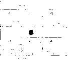
图1示出了将LED作为光源的DMD显示设备。DMD显示装置采用与红色、绿色和蓝色(RGB)的各种颜色对应的多个LED模块210。Figure 1 shows a DMD display device using LEDs as light sources. The DMD display device employs a plurality of
LED模块210通过LED驱动器200驱动,被驱动的LED模块210发射红光、绿光和蓝光信号,使光穿过透镜220顺序地投影到DMD模块230上。在DMD中,几十万甚至几百万个微镜240通过微机电系统(MEMS)工艺集成到DMD模块230中,并且单独地打开和关闭。因此,投影到DMD模块230上的RGB颜色信号在屏幕250上显示预定图片。The
将LED用作光源的DMD显示设备与采用放电灯作为光源的传统显示设备相比具有许多优点。DMD显示设备的光效率高,LED的寿命比放电灯的寿命长,并且DMD显示设备不需要机械设备例如色环。A DMD display device using an LED as a light source has many advantages over a conventional display device using a discharge lamp as a light source. The light efficiency of the DMD display device is high, the lifetime of the LED is longer than that of the discharge lamp, and the DMD display device does not require mechanical devices such as a color wheel.
用于驱动LED模块210的LED驱动器200通常包括如图2中所示的电路结构。图2中的LED驱动器200可被称作开关模式驱动电路。LED驱动器200包括电流检测器、误差放大器272、PWM调制器274、栅极电路276、开关278、电感器280、第一二极管282、第二二极管284和开关组286。The
LED驱动器200通过电流检测器检测在LED模块210中流动的电流,通过误差放大器272将与检测到的电流对应的电压和目标电压Vref对比,并且输出电压差信号。The
PWM调制器274将误差放大器272的输出和预定的三角波对比,并产生脉冲宽度调制(PWM)信号。栅极电路276通过脉冲宽度调制(PWM)信号驱动开关278,该开关278可用金属氧化物半导体场效应管(MOSFET)实现。电感器280集成(integrate)方波脉冲输出,并且允许LED模块210被供给具有与开关278的开关对应的脉动(ripple)的直流电。The
由于在白光中RGB颜色的每个的光的量不同,所以在LED模块210中流动的用于RGB颜色的每个的电流IO的量应该不同,这可通过基准电压Vref来调节。开关组286包括连接到与RGB颜色的每个对应的LED模块210的分支开关,并且通过将开关组286与基准电压Vref的改变同步使得电流IO在LED模块210中流动。因此,当Vref改变时,开关Vr、Vg和Vb导通/截止,从而不同电平的电流流过不同颜色的LED。Since the amount of light for each of the RGB colors is different in white light, the amount of currentI0 for each of the RGB colors flowing in the
被LED驱动器200驱动的LED模块210包括对应于RGB颜色的每个的单一模块,该单一模块与多个LED串联/并联连接。通常使用大于20A的电流和大于20V的电压来驱动LED模块210。而且,电流IO的脉动越小,则平衡图片质量的性能的效果越好。而且,当顺序地驱动与RGB颜色的每个对应的LED模块210时,用于高的光效率的开关和瞬变现象应该更快。The
图2的开关模式的驱动电路相对于高功率足以确保高效率。然而,因为使用电感器减小了脉动电流,所以开关频率必须增加或者电感器必须具有大的电感。当电感增加时,瞬变现象变慢,从而降低了光效率。The switching mode drive circuit of FIG. 2 is sufficient to ensure high efficiency with respect to high power. However, since the pulsating current is reduced using the inductor, the switching frequency must be increased or the inductor must have a large inductance. As the inductance increases, the transient slows down, reducing light efficiency.
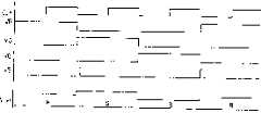
如果用如图3的上部分中示出的一对波形所示的间断电流模式(DCM)来驱动LED驱动器200,则死区加长,在死区中,由于具有大的电感的电感器的慢的瞬变现象导致DMD不能工作,从而降低了光效率。If the
如图3的下部分中所示的一对波形,电流IO的流动是连续电流模式(CCM),并且如果当改变LED驱动器200中的分支开关时死区减小,则光效率少量增加。然而,在改变分支开关的同时在第二二极管284中产生反相恢复电流,这可负面地影响电路的稳定性并且产生不期望的电磁干扰(EMI)。As shown in the pair of waveforms in the lower part of FIG. 3, the flow of currentI0 is continuous current mode (CCM), and if the dead zone is reduced when changing the branch switch in
例如,当大约20A的电流在LED模块210中流动时产生的反相恢复电流可为几十或几百安培。当反相恢复电流流过LED模块210时,加速了LED的劣化。而且,DMD模块一直截止直到反相恢复电流消失且电路稳定为止,从而降低了光效率。For example, the reverse recovery current generated when a current of about 20A flows in the
因此,需要通过使分支开关中的死区最小化而不引起反相恢复电流以及通过电流IO的充电和放电斜度增加提高瞬变响应来增加光效率。LED驱动器200的电流IO的充电和放电斜度如等式1和等式2所示:Therefore, there is a need to increase the light efficiency by minimizing the dead zone in the branch switch without inducing reverse recovery current and increasing the charge and discharge slope through the currentIO to improve the transient response. The charging and discharging slopes of the currentI0 of the
[等式1][equation 1]
其中,Vcc表示电源电压,VD是对二极管施加的电压,L是电感器280的电感。因为VD是不变的,所以等式2中给出的放电斜度也对应于预定电感不变。同时,由于Vcc可被改变,所以充电斜度可改变。Here, Vcc represents the power supply voltage, VD represents the voltage applied to the diode, and L represents the inductance of the
电流的充电和放电斜度应该尽可能大以获得用于高的光效率的快的瞬变响应。当放电斜度固定时,用于快的瞬变响应的充电斜度可被增加。然而,为了充分地增加充电斜度,电源电压Vcc太大。例如,电源电压Vcc应该为LED电压VD的两倍,即Vcc=2VD,以使充电斜度和放电斜度相等。然而,由于电源电压变大,因此开关噪音和EMI变大,需要能够抵挡更高电压的元件,从而增加了制造成本。The charge and discharge slope of the current should be as large as possible to obtain a fast transient response for high light efficiency. While the discharge slope is fixed, the charge slope for fast transient response can be increased. However, in order to sufficiently increase the charging slope, the power supply voltage Vcc is too large. For example, the power supply voltage Vcc should be twice the LED voltage VD , that is, Vcc=2VD , so that the charging slope and the discharging slope are equal. However, as the power supply voltage becomes larger, switching noise and EMI become larger, and components that can withstand higher voltages are required, thereby increasing manufacturing costs.
发明内容Contents of invention
因此,本发明的一方面提供了一种提高光效率的同时以低电压驱动LED的LED马区动器。Accordingly, an aspect of the present invention provides an LED driver driving an LED at a low voltage while improving light efficiency.
本发明的其它方面和/或优点将在下面的描述中部分地提到,一部分将从描述而清楚,或者可从本发明的实践获知。Other aspects and/or advantages of the invention will be set forth in part in the description which follows, and in part will be apparent from the description, or can be learned by practice of the invention.
通过提供一种用于驱动多个发光二极管(LED)的LED驱动器获得了本发明的前面和/或其它方面,其中,所述LED驱动器包括:电流控制器,控制预定电源单元的电源供给,以使在多个LED中流动的电流达到预定的目标电流值,其中,目标电流值对应于各发光二极管顺序地改变;多个分支开关,使电流在相对于多个LED的每个中流动或者截断在相对于多个LED的每个中的电流;旁路开关,与多个分支开关和多个LED并联连接,以通过开路或短路来选择性地将对多个LED供给的电流旁路;开关控制器,对应于目标电流值的改变来顺序地打开和闭合多个分支开关,并且对应于目标电流值的增加,在对LED供给的电流增加时,将旁路开关控制为短路。The foregoing and/or other aspects of the present invention are achieved by providing an LED driver for driving a plurality of light emitting diodes (LEDs), wherein the LED driver includes: a current controller controlling the power supply of a predetermined power supply unit to making the current flowing in a plurality of LEDs reach a predetermined target current value, wherein the target current value is sequentially changed corresponding to each light-emitting diode; a plurality of branch switches, making the current flow in each of the plurality of LEDs or cutting off current in each of the plurality of LEDs; a bypass switch connected in parallel with the plurality of branch switches and the plurality of LEDs to selectively bypass the current supplied to the plurality of LEDs by opening or shorting; the switch The controller sequentially opens and closes the plurality of branch switches corresponding to a change in the target current value, and controls the bypass switch to be short-circuited when the current supplied to the LED increases corresponding to an increase in the target current value.
根据本发明的一方面,电流控制器包括:开关,供给或截断电源单元的电源;电流检测器,检测在多个LED中流动的电流;误差放大器,将电流检测器检测到的电流和目标电流值对比,并且输出与电流和目标电流值之差对应的信号;脉冲宽度调制器,产生与误差放大器的输出信号对应的脉冲宽度调制信号,将其输出;开关驱动器,通过根据脉冲宽度调制信号输出打开和关闭开关的信号来驱动开关;电感器,串联连接在电源单元和多个发光二极管之间,并且通过电源单元的供给和截断电源来集成方波电流;二极管,如果开关截止则使在电感器中流动的电流空转。According to an aspect of the present invention, the current controller includes: a switch for supplying or cutting off the power of the power supply unit; a current detector for detecting the current flowing in the plurality of LEDs; an error amplifier for converting the current detected by the current detector to the target current Value comparison, and output a signal corresponding to the difference between the current and the target current value; the pulse width modulator generates a pulse width modulation signal corresponding to the output signal of the error amplifier, and outputs it; the switch driver outputs the pulse width modulation signal according to the pulse width modulation signal The signal to turn on and off the switch drives the switch; the inductor, which is connected in series between the power supply unit and a plurality of light-emitting diodes, and integrates a square wave current by supplying and cutting off the power of the power supply unit; the diode, which makes the inductance if the switch is turned off The current flowing in the device idles.
根据本发明的一方面,开关控制器包括:计数器,计数具有预定频率的时钟信号,并且顺序输出分别对应于多个分支开关的信号;解码器,将计数器的输出信号解码,并且依次并行输出逻辑高状态的脉冲信号;分支开关驱动器,与当解码器的各输出信号变为逻辑高状态或变为逻辑低状态时对应,使分支开关短路或打开分支开关;旁路开关驱动器,如果解码器的输出信号的逻辑状态对应于目标电流值的增加而改变,则使旁路开关短路。According to an aspect of the present invention, the switch controller includes: a counter, which counts clock signals with a predetermined frequency, and sequentially outputs signals respectively corresponding to a plurality of branch switches; a decoder, which decodes the output signals of the counter, and sequentially outputs logic signals in parallel High-state pulse signal; branch switch driver, corresponding to when each output signal of the decoder becomes a logic high state or becomes a logic low state, short-circuits the branch switch or opens the branch switch; bypass switch driver, if the decoder's A change in logic state of the output signal corresponding to an increase in the target current value shorts the bypass switch.
根据本发明的一方面,如果旁路开关闭合,则当在旁路开关中流动的电流达到目标电流值时,旁路开关驱动器将旁路开关打开。According to an aspect of the present invention, if the bypass switch is closed, the bypass switch driver opens the bypass switch when the current flowing in the bypass switch reaches a target current value.
根据本发明的一方面,LED驱动器还包括:微型计算机,相对于解码器的各脉冲信号输出与位于逻辑高状态的信号对应的目标电流值的数据;DA(数模)转换器,将从微型计算机输出的目标电流值的数据转换为模拟信号,将该信号供给到电流控制器。According to an aspect of the present invention, the LED driver also includes: a microcomputer, outputting data of a target current value corresponding to a signal in a logic high state with respect to each pulse signal of the decoder; The data of the target current value output by the computer is converted into an analog signal, and the signal is supplied to the current controller.
附图说明Description of drawings
结合附图对实施例进行的以下描述中,本发明的上面和/或其它方面及优点将变得清楚和更容易理解,其中:The above and/or other aspects and advantages of the present invention will become clear and easier to understand in the following description of the embodiments in conjunction with the accompanying drawings, wherein:
图1示出了使用传统LED驱动器的数字微镜装置(DMD)显示设备的结构;Figure 1 shows the structure of a digital micromirror device (DMD) display device using a conventional LED driver;
图2示出了图1中的LED驱动器的电路结构;Fig. 2 shows the circuit structure of the LED driver in Fig. 1;
图3示出了图1中示出的LED驱动器的栅极电压和LED电流的波形;Figure 3 shows the waveforms of the gate voltage and LED current of the LED driver shown in Figure 1;
图4示出了根据本发明实施例的LED驱动器的电路结构;Fig. 4 shows the circuit structure of the LED driver according to the embodiment of the present invention;
图5示出了图4中示出的LED驱动器的目标电压、栅极电压和LED电流的波形;Fig. 5 shows the waveforms of target voltage, gate voltage and LED current of the LED driver shown in Fig. 4;
图6示出了图4中示出的LED驱动器的开关控制器的内部结构;Fig. 6 shows the internal structure of the switch controller of the LED driver shown in Fig. 4;
图7示出了图6中示出的开关控制器的各个电压和电流的波形。FIG. 7 shows waveforms of various voltages and currents of the switch controller shown in FIG. 6 .
整个附图中,相同的标号将被理解为表示相同的元件、零件和结构。Throughout the drawings, like reference numerals will be understood to refer to like elements, parts and structures.
具体实施方式 Detailed ways
现在,将详细描述本发明的示例性实施例,附图中示出了这些实施例。下面描述的示例性实施例不意图限制本发明而是提供对本发明的更好的理解。图4示出了根据本发明实施例的LED驱动器10的结构。Now, exemplary embodiments of the present invention, which are shown in the accompanying drawings, will be described in detail. The exemplary embodiments described below are not intended to limit the present invention but to provide a better understanding of the present invention. Fig. 4 shows the structure of the
LED驱动器10驱动多个LED 30,该LED 30作为数字微镜装置(DMD)显示设备例如使用DMD的数字光学处理(DLP)投影TV、投影机等的光源以及LCD背光灯。The
如图4中所示,LED驱动器10包括电流控制器12、多个分支开关14、旁路开关16和开关控制器18。多个分支开关位于电流控制器12和多个LED30的阳极之间。多个LED 30的阴极与电流控制器12连接。旁路开关16与多个分支开关14和多个LED 30并联连接。各分支开关14与多个LED 30中的一个串联连接。优选地,多个LED 30中的每个作为包括与红色、绿色或蓝色对应的多个LED的模块。As shown in FIG. 4 , the
电流控制器12使得在多个LED 30中流动的电流IO达到预定目标电流值。即,电流控制器12将来自预定电源单元的电源Vcc控制为相对于LED 30施加或切断。这里,目标电流值表示将被施加到多个LED 30的电流。目标电流值被对应于LED 30预置,并且以预定间隔根据红色、绿色和蓝色的顺序被顺序地改变。The
如图4中所示,电流控制器12包括电流检测器122、误差放大器124、脉冲宽度调制器126、开关驱动器128、开关130、电感器132和二极管134。As shown in FIG. 4 ,
电流检测器122检测在多个LED 30中流动的电流IO。电流检测器122可用具有预定电阻的电阻器来实现,其中,电流检测器122的第一端与多个LED 30连接,电流检测器122的第二端接地。在此实施例中,在多个LED 30中流动的电流IO可根据电流IO流过电流检测器122产生的电压和电流检测器122的电阻来计算。当然,在不脱离本发明的范围和精神的情况下,任何其它适合的电流检测器都能用作设计选择的电流检测器。The
电感器132的第一端与开关130的第一端和二极管134的阴极连接,电感器132的第二端与多个LED 30连接。在电感器132中流动的电流等于在多个LED 30和旁路开关16的组合中流动的总电流。优先地,二极管134的阳极接地。A first end of the
优选地,开关130用金属氧化物半导体场效应管(MOSFET)来实现。开关130的栅极与开关驱动器128的输出端连接,开关130的漏极与电源单元连接并且接收电压Vcc。另外,开关130的源极与电感器132的第一端以及二极管134的阴极连接。Preferably, the
开关130根据对栅极施加的栅极电压的逻辑状态导通和截止,以执行开关操作。如果开关130导通,电流流过漏极和源极,对电感器132施加电源电压Vcc。The
当对电感器132施加Vcc时,流过电感器的电流增加直到在电感器132中流动的电流被充电为预定电平。如果开关130截止,则流过漏极、源极的电流被截断,充在电感器132中的电流从二极管134传播并流过LED 30。当开关130截止时,由于电源被截断,从而电流IO以基于电感器132的电感的速率下降。When Vcc is applied to the
误差放大器124在反相输入端从电流检测器122接收与在多个LED 30中流动的电流IO对应的电压,在非反相输入端接收与目标电流值对应的预定目标电压Vref。误差放大器124放大与在LED 30中流动的电流IO对应的电压和目标电压Vref之间的电压差,并将该电压差作为输出信号输出。The
脉冲宽度调制器126产生与误差放大器124的输出信号对应的脉冲宽度调制信号,将其输出。开关驱动器128根据从脉冲宽度调制器126输出的脉冲宽度调制信号来输出打开和闭合开关130的信号。即,该实施例的电流控制器12检测在LED 30中流动的电流IO并且控制开关130直到电流IO达到预定目标值为止。The
多个分支开关14与LED 30的阳极连接。分支开关14被导通和截止以供给和截断对应于LED 30的每个颜色的电流IO。优选地,多个分支开关14用金属氧化物半导体场效应管(MOSFET)来实现。A plurality of branch switches 14 are connected to anodes of
旁路开关16与多个分支开关14和多个LED 30并联连接,并且旁路开关16根据开关控制器18的控制信号而打开或短路来允许电流IO旁路多个LED 30。旁路开关16也可优选地用MOSFET来实现。The
开关控制器18对应于目标电流值的变化顺序地打开和闭合多个分支开关14,并且将旁路开关16控制为在对多个LED 30供给的电流对应于目标电流值的增加而增加的间隔期间短路。图5示出了驱动开关控制器18的目标电压Vref、对各个分支开关14和旁路开关16的栅极施加的栅极电压VR、VG、VB和VS以及在LED 30中流动的电流IO的波形。The
如果目标电流值增加,则与目标电流值对应的目标电压Vref增加,开关控制器18导通旁路开关16,从而将对LED 30施加的电流旁路。当不对LED30施加电流IO时,LED 30没有电压降,并且电流值的增加速率被最大化。如果目标电流值增加,则电源电压可被最小化。电流IO的充电斜度和放电斜度如以下的等式3和等式4所示。If the target current value increases, the target voltage Vref corresponding to the target current value increases, and the
如上所述,所需电源电压Vcc为Vcc=VD,以使电流IO的充电斜度和放电斜度彼此相等。因此,通过如上所述的远小于2VD的电源电压并结合传统排列可获得相同的瞬变响应时间。同时,当电流IO的增加速率被最大化时,电流IO达到目标电流值的时间即瞬变响应时间可被最小化。As described above, the required power supply voltage Vcc is Vcc=VD so that the charging slope and the discharging slope of the current IO are equal to each other. Therefore, the same transient response time can be obtained with a supply voltage much less than 2VD as described above combined with a conventional arrangement. Meanwhile, when the rate of increase of the currentIO is maximized, the time for the currentIO to reach the target current value, ie, the transient response time, can be minimized.
如图6中所示,示例性开关控制器18包括计数器182、解码器184、分支开关驱动器188和旁路开关驱动器186。As shown in FIG. 6 , the
计数器182接收具有预定频率的时钟信号(图7中的CLK),并且计数时钟信号,顺序输出分别与RGB颜色的分支开关14对应的信号Q[1...0]。即,计数器182是计数时钟信号的三进制计数器,并且输出用于与各RGB颜色对应的三种情况的两位输出信号(00→01→10→00..)。解码器184将计数器182的输出信号解码并且依次并行输出具有逻辑高状态的脉冲信号。即,解码器184从计数器182接收表示与各RGB颜色对应的三种情况的两位信号(00→01→10→00..),并且解码所述两位信号以使通过三个输出端口的三个脉冲信号顺序地为逻辑高状态。The
如果计数器182的输出信号为“00”,则本实施例的解码器184使得与“R”对应的信号为逻辑高状态,并且与“G”和“B”对应的信号为逻辑低状态。如果计数器182的输出信号为“01”,则解码器184使得与“G”对应的信号为逻辑高状态,并且与“B”和“R”对应的信号为逻辑低状态。如果计数器182的输出信号为“10”,则解码器184使得与“B”对应的信号为逻辑高状态,并且与“R”和“G”对应的信号为逻辑低状态。优选地,与R、G、B中的一对对应的脉冲信号的逻辑状态的改变以预定间隔同时发生。If the output signal of the
当解码器184的各个输出信号变为逻辑高状态或逻辑低状态时,分支开关驱动器188对分支开关14的栅极输出导通和截止分支开关14的栅极信号(图7中的VR、VG和VB)。When each output signal of the
如果解码器184的输出信号的逻辑状态对应于目标电流值的增加而改变,则旁路开关驱动器186对旁路开关16的栅极输出栅极信号VS,这使得旁路开关16短路。旁路开关驱动器186对应于R、G和B中的目标电流值的增加接收解码器184的输出信号,并且当对应信号的逻辑状态改变时,在预定的时间段输出处于高状态的栅极信号VS。如果目标电流值的大小为G>R>B,则如果目标电流值增加,即当目标电流值从“R”到“G”和从“B”到“R”改变时,旁路开关驱动器186在预定的时间段内输出逻辑高状态的栅极信号VS。If the logic state of the output signal of the
优先地,旁路开关驱动器186接收与“G”和“R”对应的信号,检测栅极信号VS的逻辑状态是否改变为高状态,从而可改变栅极信号VS的逻辑状态。在另一个实施例中,旁路开关驱动器186接收与“R”和“B”对应的信号,检测其逻辑状态是否改变为低状态,从而可改变栅极信号VS的逻辑状态。在任一情况下,旁路开关驱动器186接收其大小对应于R、G和B预置的目标电流值,检测对应于目标电流值的增加的颜色的解码器184的输出信号。Preferably, the
如果目标电流值增加,优选地,旁路开关驱动器186保持栅极信号VS的逻辑状态直到电流IO达到目标电流值为止。因此,电流IO达到目标电流值的时间,即对应于目标电流值的增加的瞬变响应时间被最小化。If the target current value increases,
LED驱动器10可包括微型计算机20,以相对解码器184的各脉冲信号输出表示与位于逻辑高状态的信号对应的目标电流值的数据。微型计算机20对应于将被输出的图像信号的R、G和B的值预先设置表示多个LED 30的目标电流值IR、IG和IB的数据。另外,微型计算机20接收与R、G和B对应的三个脉冲信号。顺序地,微型计算机20检测各脉冲信号的逻辑状态并且输出表示与位于逻辑高状态的脉冲信号的颜色对应的目标电流值IR、IG或IB的数据。微型计算机20输出与目标电流值IR、IG或IB对应的目标电压Vref的数据。微型计算机20可用普通的微处理器来实现,并且如果必要可包括存储器例如ROM和RAM。The
LED驱动器10还可包括DA(数模)转换器22,该转换器22将从微型计算机20输出的表示目标电流值IR、IG或IB的数据转换为模拟信号,并且将它们提供到电流控制器12。The
尽管已经示出和描述了本发明的一些实施例,但是本领域的技术人员应该理解,在不脱离由权利要求及其等同物限定的本发明的原理和精神的情况下,可对这些实施例作改变。While certain embodiments of the present invention have been shown and described, it should be understood by those skilled in the art that changes may be made to these embodiments without departing from the principles and spirit of the invention as defined by the claims and their equivalents. make changes.
本申请要求2005年2月26日在韩国知识产权局提交的第2005-0016209号韩国专利申请的权益,其公开通过引用被包含于此。This application claims the benefit of Korean Patent Application No. 2005-0016209 filed in the Korean Intellectual Property Office on February 26, 2005, the disclosure of which is hereby incorporated by reference.
Claims (6)
Translated fromChineseApplications Claiming Priority (2)
| Application Number | Priority Date | Filing Date | Title |
|---|---|---|---|
| KR1020050016209AKR100628718B1 (en) | 2005-02-26 | 2005-02-26 | LED drive system |
| KR1020050016209 | 2005-02-26 |
Publications (2)
| Publication Number | Publication Date |
|---|---|
| CN1825401Atrue CN1825401A (en) | 2006-08-30 |
| CN100481164C CN100481164C (en) | 2009-04-22 |
Family
ID=36931533
Family Applications (1)
| Application Number | Title | Priority Date | Filing Date |
|---|---|---|---|
| CNB2006100033585AExpired - Fee RelatedCN100481164C (en) | 2005-02-26 | 2006-01-26 | LED driver |
Country Status (3)
| Country | Link |
|---|---|
| US (1) | US7728798B2 (en) |
| KR (1) | KR100628718B1 (en) |
| CN (1) | CN100481164C (en) |
Cited By (12)
| Publication number | Priority date | Publication date | Assignee | Title |
|---|---|---|---|---|
| CN101720150A (en)* | 2008-10-09 | 2010-06-02 | 夏普株式会社 | LED drive circuit, LED lighting device, LED lighting apparatus, and LED lighting system |
| CN101169920B (en)* | 2006-10-25 | 2012-04-18 | 三星电子株式会社 | Display apparatus and control method thereof |
| CN102473379A (en)* | 2009-07-17 | 2012-05-23 | 普瑞光电股份有限公司 | Reconfigurable LED Arrays and Uses in Lighting Systems |
| CN102484915A (en)* | 2009-08-14 | 2012-05-30 | 欧司朗股份有限公司 | Circuit arrangement for operating a plurality of LEDs for a micromirror arrangement |
| CN102625522A (en)* | 2011-01-31 | 2012-08-01 | 朗捷科技股份有限公司 | High-brightness alternating current LED lamp driving circuit |
| CN102629451A (en)* | 2012-05-09 | 2012-08-08 | 深圳市华星光电技术有限公司 | LED (Light Emitting Diode) backlight driving circuit, liquid crystal display device and driving method |
| CN103052207A (en)* | 2011-10-14 | 2013-04-17 | 欧司朗股份有限公司 | Circuit for driving light sources, relative lighting system and method of driving light sources |
| TWI486095B (en)* | 2012-11-01 | 2015-05-21 | Univ Nat Yunlin Sci & Tech | Light-emitting diode driving device for digitally regulating output power |
| CN108575027A (en)* | 2017-03-14 | 2018-09-25 | 英飞凌科技股份有限公司 | System and method for driving light emitting diode and system for preventing current overshoot |
| CN110278626A (en)* | 2018-03-14 | 2019-09-24 | 英飞凌科技股份有限公司 | LED driver for load change |
| CN110741733A (en)* | 2017-06-12 | 2020-01-31 | 昕诺飞控股有限公司 | Method and device for driving LED |
| CN115762401A (en)* | 2022-11-14 | 2023-03-07 | 重庆惠科金渝光电科技有限公司 | Organic light emitting diode display circuit and display device |
Families Citing this family (48)
| Publication number | Priority date | Publication date | Assignee | Title |
|---|---|---|---|---|
| US7538473B2 (en)* | 2004-02-03 | 2009-05-26 | S.C. Johnson & Son, Inc. | Drive circuits and methods for ultrasonic piezoelectric actuators |
| US7723899B2 (en) | 2004-02-03 | 2010-05-25 | S.C. Johnson & Son, Inc. | Active material and light emitting device |
| EP1758072A3 (en)* | 2005-08-24 | 2007-05-02 | Semiconductor Energy Laboratory Co., Ltd. | Display device and driving method thereof |
| KR20070072142A (en)* | 2005-12-30 | 2007-07-04 | 엘지.필립스 엘시디 주식회사 | EL display device and driving method |
| US8791645B2 (en) | 2006-02-10 | 2014-07-29 | Honeywell International Inc. | Systems and methods for controlling light sources |
| KR100917623B1 (en)* | 2006-02-13 | 2009-09-17 | 삼성전자주식회사 | LED driver |
| US20070236518A1 (en)* | 2006-04-03 | 2007-10-11 | Oto Leonard D | Hysteretic led driver with low end linearization |
| JP5667361B2 (en)* | 2006-09-20 | 2015-02-12 | コーニンクレッカ フィリップス エヌ ヴェ | Light emitting element control system and lighting system having the system |
| JP2008130907A (en)* | 2006-11-22 | 2008-06-05 | Samsung Electronics Co Ltd | Light source lighting drive device |
| US7859196B2 (en) | 2007-04-25 | 2010-12-28 | American Bright Lighting, Inc. | Solid state lighting apparatus |
| KR100864254B1 (en)* | 2007-07-03 | 2008-10-17 | 정강화 | Building lighting sequential flashing control circuit and building lighting system having the same |
| CN101779522B (en)* | 2007-07-23 | 2014-11-19 | Nxp股份有限公司 | Led arrangement with bypass driving |
| US8188679B2 (en)* | 2007-07-23 | 2012-05-29 | Nxp B.V. | Self-powered LED bypass-switch configuration |
| DE102007044476A1 (en)* | 2007-09-18 | 2009-03-19 | Osram Gesellschaft mit beschränkter Haftung | Lighting unit and method for controlling the lighting unit |
| TW200919410A (en)* | 2007-10-26 | 2009-05-01 | Quanta Comp Inc | Driving apparatus, backlight module, and driving method |
| US20090189842A1 (en)* | 2008-01-24 | 2009-07-30 | Industrial Technology Research Institute | Backlight control apparatus |
| US8508204B2 (en) | 2008-03-19 | 2013-08-13 | Nxp B.V. | Controller and method of operating a controller |
| KR20090109435A (en)* | 2008-04-15 | 2009-10-20 | 삼성전자주식회사 | Light source driving device, light source driving method and display device |
| CN101588664B (en)* | 2008-05-21 | 2012-12-05 | 原景科技股份有限公司 | LED driving circuit and circuit for controlling power switch |
| EP2319279A4 (en)* | 2008-08-21 | 2014-12-03 | American Bright Lighting Inc | Led light engine |
| US8773336B2 (en)* | 2008-09-05 | 2014-07-08 | Ketra, Inc. | Illumination devices and related systems and methods |
| US8129916B2 (en)* | 2008-09-26 | 2012-03-06 | Cypress Semiconductor Corporation | Light emitting driver circuit with bypass and method |
| US8093835B2 (en)* | 2008-09-26 | 2012-01-10 | Cypress Semiconductor Corporation | Light emitting driver circuit with compensation and method |
| US8058817B2 (en)* | 2008-09-30 | 2011-11-15 | O2Micro, Inc. | Power systems with current regulation |
| US8111023B2 (en)* | 2008-12-18 | 2012-02-07 | National Chi Nan University | Control system for different colors of light emitting diodes |
| ITMI20090020A1 (en)* | 2009-01-13 | 2010-07-14 | Telsey S P A | METHOD AND POWER SUPPLY SYSTEM FOR LED LIGHTING |
| KR101119261B1 (en)* | 2009-01-14 | 2012-03-16 | 삼성전자주식회사 | Driver for light source |
| KR20100103262A (en)* | 2009-03-13 | 2010-09-27 | 삼성전자주식회사 | Driver for light source |
| EP2448013A4 (en)* | 2009-06-26 | 2014-03-12 | Panasonic Corp | LIGHT EMITTING ELEMENT ATTACHING DEVICE, FLAT LIGHTING DEVICE, AND LIQUID CRYSTAL DISPLAY |
| US8471486B2 (en) | 2010-04-21 | 2013-06-25 | Taiwan Semiconductor Manufacturing Company, Ltd. | Energy-saving mechanisms in multi-color display devices |
| KR101092508B1 (en) | 2010-05-18 | 2011-12-13 | 주식회사 티엘아이 | LED lighting device that changes the connection type according to the applied voltage level |
| EP2595838A4 (en) | 2010-07-22 | 2015-03-11 | Independence Led Lighting Llc | Light engine device with direct to linear system driver |
| US8669709B2 (en) | 2010-08-27 | 2014-03-11 | American Bright Lighting, Inc. | Solid state lighting driver with THDi bypass circuit |
| GB201018417D0 (en)* | 2010-11-01 | 2010-12-15 | Gas Sensing Solutions Ltd | Apparatus and method for generating light pulses from LEDs in optical absorption gas sensors |
| DE102011004882B4 (en)* | 2011-03-01 | 2020-07-23 | Osram Gmbh | Luminaire unit with lighting unit and projection unit |
| KR20120114813A (en) | 2011-04-08 | 2012-10-17 | 삼성디스플레이 주식회사 | Dc-dc converter and driving device of light source for display device using the same |
| WO2012172420A1 (en)* | 2011-06-17 | 2012-12-20 | Stevan Pokrajac | Light emitting diode driver circuit |
| US8581519B2 (en) | 2011-08-25 | 2013-11-12 | Hong Kong Applied Science & Technology Research Institute Co., Ltd. | Current-switching LED driver using DAC to ramp bypass currents to accelerate switching speed and reduce ripple |
| US8760129B2 (en) | 2011-12-29 | 2014-06-24 | Infineon Technologies Austria Ag | Low EMI driver circuit |
| US20130300770A1 (en)* | 2012-05-09 | 2013-11-14 | Xiang Yang | LED Backlight Driving Circuit, Liquid Crystal Display Device, and Driving Method |
| JP5958146B2 (en)* | 2012-07-23 | 2016-07-27 | セイコーエプソン株式会社 | Projector and projector control method |
| KR101734916B1 (en) | 2015-03-09 | 2017-05-15 | 한지연 | Power Control Apparatus For LED |
| JP6998565B2 (en)* | 2017-03-01 | 2022-01-18 | パナソニックIpマネジメント株式会社 | Lighting devices, lighting fixtures and electronic devices |
| US10172207B1 (en)* | 2018-01-02 | 2019-01-01 | Dong Guan Bright Yinhuey Lighting Co., Ltd. | Adjustable light color temperature switching circuit |
| US10777617B2 (en)* | 2018-11-16 | 2020-09-15 | Osram Opto Semiconductors Gmbh | Display, a circuit arrangement for a display, and a method of operating a circuit arrangement of a display |
| JP7480709B2 (en)* | 2018-11-29 | 2024-05-10 | 日本精機株式会社 | Display device |
| CN111341230B (en)* | 2018-12-19 | 2024-06-25 | 青岛海信激光显示股份有限公司 | Projection display device and control method thereof |
| CN116794917A (en)* | 2022-03-18 | 2023-09-22 | 中强光电股份有限公司 | Projection device, illumination device thereof and light source driving method |
Family Cites Families (26)
| Publication number | Priority date | Publication date | Assignee | Title |
|---|---|---|---|---|
| JPH05158430A (en)* | 1991-12-03 | 1993-06-25 | Rohm Co Ltd | Display device |
| US6618031B1 (en)* | 1999-02-26 | 2003-09-09 | Three-Five Systems, Inc. | Method and apparatus for independent control of brightness and color balance in display and illumination systems |
| JP4013420B2 (en) | 1999-09-06 | 2007-11-28 | セイコーエプソン株式会社 | LIGHTING DEVICE AND ITS DRIVE METHOD, LIQUID CRYSTAL DEVICE, AND ELECTRONIC DEVICE |
| US7262752B2 (en)* | 2001-01-16 | 2007-08-28 | Visteon Global Technologies, Inc. | Series led backlight control circuit |
| JP3957150B2 (en)* | 2001-02-08 | 2007-08-15 | セイコーインスツル株式会社 | LED drive circuit |
| JP2002244619A (en) | 2001-02-15 | 2002-08-30 | Sony Corp | Circuit for driving led display device |
| DE10115388A1 (en)* | 2001-03-28 | 2002-10-10 | Patent Treuhand Ges Fuer Elektrische Gluehlampen Mbh | Control circuit for an LED array |
| JP2004527003A (en)* | 2001-04-26 | 2004-09-02 | コーニンクレッカ フィリップス エレクトロニクス エヌ ヴィ | Display device |
| US20030095086A1 (en)* | 2001-09-21 | 2003-05-22 | Juergen Neuhaeusler | Circuit configuration for driving a set of at least one light-emitting diode |
| JP2003186437A (en) | 2001-12-18 | 2003-07-04 | Sanyo Electric Co Ltd | Display device |
| JP3854173B2 (en) | 2002-02-27 | 2006-12-06 | 東北パイオニア株式会社 | Driving method of light emitting display panel and organic EL display device |
| US6798152B2 (en)* | 2002-08-21 | 2004-09-28 | Freescale Semiconductor, Inc. | Closed loop current control circuit and method thereof |
| JP2004093761A (en) | 2002-08-30 | 2004-03-25 | Toko Inc | Backlight device |
| JP2004157225A (en) | 2002-11-05 | 2004-06-03 | Plus Vision Corp | Projector and image projection method therefor |
| US20040090403A1 (en)* | 2002-11-08 | 2004-05-13 | Dynascan Technology Corp. | Light-emitting diode display apparatus with low electromagnetic display |
| JP2004311635A (en)* | 2003-04-04 | 2004-11-04 | Olympus Corp | DRIVE DEVICE, LIGHTING DEVICE USING THE SAME, AND DISPLAY DEVICE USING THE LIGHTING DEVICE |
| US7079092B2 (en) | 2003-04-25 | 2006-07-18 | Barco Nv | Organic light-emitting diode (OLED) pre-charge circuit for use in a common anode large-screen display |
| EP1623603A1 (en)* | 2003-05-07 | 2006-02-08 | Koninklijke Philips Electronics N.V. | Single driver for multiple light emitting diodes |
| US20040227704A1 (en) | 2003-05-14 | 2004-11-18 | Wen-Chun Wang | Apparatus for improving yields and uniformity of active matrix oled panels |
| US20070171180A1 (en)* | 2004-02-12 | 2007-07-26 | Takashi Akiyama | Light source driving circuit, lighting apparatus, display apparatus, field sequential color liquid crystal display apparatus, and information appliance |
| JP2005257790A (en)* | 2004-03-09 | 2005-09-22 | Olympus Corp | Illumination apparatus and image projection apparatus using the same |
| TWI232426B (en)* | 2004-04-08 | 2005-05-11 | Toppoly Optoelectronics Corp | Circuitry and method for displaying of a monitor |
| US7633463B2 (en)* | 2004-04-30 | 2009-12-15 | Analog Devices, Inc. | Method and IC driver for series connected R, G, B LEDs |
| US20060038803A1 (en)* | 2004-08-20 | 2006-02-23 | Semiconductor Components Industries, Llc | LED control method and structure therefor |
| KR100628717B1 (en)* | 2005-02-26 | 2006-09-28 | 삼성전자주식회사 | LED drive system |
| US7499007B2 (en)* | 2005-04-01 | 2009-03-03 | Analog Devices, Inc. | Maximizing efficiency of battery-powered LED drivers |
- 2005
- 2005-02-26KRKR1020050016209Apatent/KR100628718B1/ennot_activeExpired - Fee Related
- 2005-11-01USUS11/263,019patent/US7728798B2/ennot_activeExpired - Fee Related
- 2006
- 2006-01-26CNCNB2006100033585Apatent/CN100481164C/ennot_activeExpired - Fee Related
Cited By (21)
| Publication number | Priority date | Publication date | Assignee | Title |
|---|---|---|---|---|
| CN101169920B (en)* | 2006-10-25 | 2012-04-18 | 三星电子株式会社 | Display apparatus and control method thereof |
| CN101720150A (en)* | 2008-10-09 | 2010-06-02 | 夏普株式会社 | LED drive circuit, LED lighting device, LED lighting apparatus, and LED lighting system |
| CN102473379A (en)* | 2009-07-17 | 2012-05-23 | 普瑞光电股份有限公司 | Reconfigurable LED Arrays and Uses in Lighting Systems |
| CN102473379B (en)* | 2009-07-17 | 2016-09-21 | 谢尼奥有限公司 | Reconfigurable LED Arrays and Uses in Lighting Systems |
| CN102484915A (en)* | 2009-08-14 | 2012-05-30 | 欧司朗股份有限公司 | Circuit arrangement for operating a plurality of LEDs for a micromirror arrangement |
| CN102484915B (en)* | 2009-08-14 | 2014-12-03 | 欧司朗股份有限公司 | Circuit arrangement for operating multiple LEDs for micromirror arrangement |
| US9125262B2 (en) | 2009-08-14 | 2015-09-01 | Osram Gmbh | Circuit configuration for operating LEDs for a micromirror arrangement |
| CN102625522A (en)* | 2011-01-31 | 2012-08-01 | 朗捷科技股份有限公司 | High-brightness alternating current LED lamp driving circuit |
| CN103052207B (en)* | 2011-10-14 | 2015-11-18 | 欧司朗股份有限公司 | For the method for the circuit of driving light source, related lighting system and driving light source |
| CN103052207A (en)* | 2011-10-14 | 2013-04-17 | 欧司朗股份有限公司 | Circuit for driving light sources, relative lighting system and method of driving light sources |
| CN102629451A (en)* | 2012-05-09 | 2012-08-08 | 深圳市华星光电技术有限公司 | LED (Light Emitting Diode) backlight driving circuit, liquid crystal display device and driving method |
| TWI486095B (en)* | 2012-11-01 | 2015-05-21 | Univ Nat Yunlin Sci & Tech | Light-emitting diode driving device for digitally regulating output power |
| CN108575027A (en)* | 2017-03-14 | 2018-09-25 | 英飞凌科技股份有限公司 | System and method for driving light emitting diode and system for preventing current overshoot |
| US10420178B2 (en) | 2017-03-14 | 2019-09-17 | Infineon Technologies Ag | Light emitting diode driver for load and supply changes |
| CN108575027B (en)* | 2017-03-14 | 2020-01-03 | 英飞凌科技股份有限公司 | System and method for driving light emitting diode and system for preventing current overshoot |
| CN110741733A (en)* | 2017-06-12 | 2020-01-31 | 昕诺飞控股有限公司 | Method and device for driving LED |
| CN110741733B (en)* | 2017-06-12 | 2023-04-04 | 昕诺飞控股有限公司 | Method and device for driving LED |
| CN110278626A (en)* | 2018-03-14 | 2019-09-24 | 英飞凌科技股份有限公司 | LED driver for load change |
| CN110278626B (en)* | 2018-03-14 | 2024-04-12 | 英飞凌科技股份有限公司 | LED driver for load changes |
| CN115762401A (en)* | 2022-11-14 | 2023-03-07 | 重庆惠科金渝光电科技有限公司 | Organic light emitting diode display circuit and display device |
| CN115762401B (en)* | 2022-11-14 | 2024-01-26 | 重庆惠科金渝光电科技有限公司 | Organic light emitting diode display circuit and display device |
Also Published As
| Publication number | Publication date |
|---|---|
| US7728798B2 (en) | 2010-06-01 |
| KR100628718B1 (en) | 2006-09-28 |
| KR20060094768A (en) | 2006-08-30 |
| CN100481164C (en) | 2009-04-22 |
| US20060192728A1 (en) | 2006-08-31 |
Similar Documents
| Publication | Publication Date | Title |
|---|---|---|
| CN1825401A (en) | LED driver | |
| CN1826030A (en) | LED driver | |
| JP4559364B2 (en) | LED drive device | |
| US8569975B2 (en) | Control circuit for switching power supply | |
| US8004213B2 (en) | Power supply, light emission control device and display device | |
| KR101712676B1 (en) | PWM controlling circuit and LED driver circuit having the same in | |
| KR101563208B1 (en) | Light source driving device and light source device including the same | |
| TWI658748B (en) | Dimming controller capable of receiving pulse width modulation signal and DC signal and related dimming method | |
| US8159419B2 (en) | Display apparatus and control method thereof | |
| CN1624534A (en) | Power supply system and liquid crystal display device having the same | |
| EP2181566A2 (en) | Multi-led control | |
| CN101569025A (en) | Light Emitting diode driving apparatus | |
| CN1932941A (en) | Display apparatus and control method thereof | |
| US20200120769A1 (en) | Light emitting diode driving device and light emitting diode backlight module | |
| CN1933692A (en) | Display apparatus and method of providing power to light source | |
| US7446481B2 (en) | Display device and control method thereof | |
| CN1790127A (en) | LED driver | |
| CN1588523A (en) | Drivers for LED strings | |
| CN1578577A (en) | Inverter circuit for lighting discharge lamps with reduced power consumption | |
| CN112020169B (en) | Light modulation controller capable of receiving pulse width modulation signal and direct current signal and light modulation method | |
| CN1779750A (en) | Light emitting diode control device and method thereof | |
| TWI697255B (en) | Dimming controllers and related dimming methods capable of receiving pulse-width-modulation signal and direct-current signal | |
| CN109996365B (en) | Dimming controller and related dimming method | |
| KR20160047711A (en) | Driving apparatus and method of Light Emitting Diode |
Legal Events
| Date | Code | Title | Description |
|---|---|---|---|
| C06 | Publication | ||
| PB01 | Publication | ||
| C10 | Entry into substantive examination | ||
| SE01 | Entry into force of request for substantive examination | ||
| C14 | Grant of patent or utility model | ||
| GR01 | Patent grant | ||
| CF01 | Termination of patent right due to non-payment of annual fee | Granted publication date:20090422 Termination date:20150126 | |
| EXPY | Termination of patent right or utility model |