CN1822395B - Semiconductor device, driving circuit and method for manufacturing semiconductor device - Google Patents
Semiconductor device, driving circuit and method for manufacturing semiconductor deviceDownload PDFInfo
- Publication number
- CN1822395B CN1822395BCN2006100090287ACN200610009028ACN1822395BCN 1822395 BCN1822395 BCN 1822395BCN 2006100090287 ACN2006100090287 ACN 2006100090287ACN 200610009028 ACN200610009028 ACN 200610009028ACN 1822395 BCN1822395 BCN 1822395B
- Authority
- CN
- China
- Prior art keywords
- mentioned
- semiconductor layer
- region
- type
- impurity range
- Prior art date
- Legal status (The legal status is an assumption and is not a legal conclusion. Google has not performed a legal analysis and makes no representation as to the accuracy of the status listed.)
- Expired - Fee Related
Links
Images


Classifications
- H—ELECTRICITY
- H10—SEMICONDUCTOR DEVICES; ELECTRIC SOLID-STATE DEVICES NOT OTHERWISE PROVIDED FOR
- H10D—INORGANIC ELECTRIC SEMICONDUCTOR DEVICES
- H10D30/00—Field-effect transistors [FET]
- H10D30/60—Insulated-gate field-effect transistors [IGFET]
- H10D30/67—Thin-film transistors [TFT]
- H10D30/6704—Thin-film transistors [TFT] having supplementary regions or layers in the thin films or in the insulated bulk substrates for controlling properties of the device
- H—ELECTRICITY
- H10—SEMICONDUCTOR DEVICES; ELECTRIC SOLID-STATE DEVICES NOT OTHERWISE PROVIDED FOR
- H10D—INORGANIC ELECTRIC SEMICONDUCTOR DEVICES
- H10D30/00—Field-effect transistors [FET]
- H10D30/01—Manufacture or treatment
- H10D30/021—Manufacture or treatment of FETs having insulated gates [IGFET]
- H10D30/0221—Manufacture or treatment of FETs having insulated gates [IGFET] having asymmetry in the channel direction, e.g. lateral high-voltage MISFETs having drain offset region or extended-drain MOSFETs [EDMOS]
- H—ELECTRICITY
- H10—SEMICONDUCTOR DEVICES; ELECTRIC SOLID-STATE DEVICES NOT OTHERWISE PROVIDED FOR
- H10D—INORGANIC ELECTRIC SEMICONDUCTOR DEVICES
- H10D30/00—Field-effect transistors [FET]
- H10D30/60—Insulated-gate field-effect transistors [IGFET]
- H10D30/601—Insulated-gate field-effect transistors [IGFET] having lightly-doped drain or source extensions, e.g. LDD IGFETs or DDD IGFETs
- H10D30/603—Insulated-gate field-effect transistors [IGFET] having lightly-doped drain or source extensions, e.g. LDD IGFETs or DDD IGFETs having asymmetry in the channel direction, e.g. lateral high-voltage MISFETs having drain offset region or extended drain IGFETs [EDMOS]
- H—ELECTRICITY
- H10—SEMICONDUCTOR DEVICES; ELECTRIC SOLID-STATE DEVICES NOT OTHERWISE PROVIDED FOR
- H10D—INORGANIC ELECTRIC SEMICONDUCTOR DEVICES
- H10D30/00—Field-effect transistors [FET]
- H10D30/60—Insulated-gate field-effect transistors [IGFET]
- H10D30/67—Thin-film transistors [TFT]
- H10D30/6704—Thin-film transistors [TFT] having supplementary regions or layers in the thin films or in the insulated bulk substrates for controlling properties of the device
- H10D30/6713—Thin-film transistors [TFT] having supplementary regions or layers in the thin films or in the insulated bulk substrates for controlling properties of the device characterised by the properties of the source or drain regions, e.g. compositions or sectional shapes
- H10D30/6715—Thin-film transistors [TFT] having supplementary regions or layers in the thin films or in the insulated bulk substrates for controlling properties of the device characterised by the properties of the source or drain regions, e.g. compositions or sectional shapes characterised by the doping profiles, e.g. having lightly-doped source or drain extensions
- H10D30/6717—Thin-film transistors [TFT] having supplementary regions or layers in the thin films or in the insulated bulk substrates for controlling properties of the device characterised by the properties of the source or drain regions, e.g. compositions or sectional shapes characterised by the doping profiles, e.g. having lightly-doped source or drain extensions the source and the drain regions being asymmetrical
- H—ELECTRICITY
- H10—SEMICONDUCTOR DEVICES; ELECTRIC SOLID-STATE DEVICES NOT OTHERWISE PROVIDED FOR
- H10D—INORGANIC ELECTRIC SEMICONDUCTOR DEVICES
- H10D62/00—Semiconductor bodies, or regions thereof, of devices having potential barriers
- H10D62/10—Shapes, relative sizes or dispositions of the regions of the semiconductor bodies; Shapes of the semiconductor bodies
- H10D62/17—Semiconductor regions connected to electrodes not carrying current to be rectified, amplified or switched, e.g. channel regions
- H10D62/351—Substrate regions of field-effect devices
- H10D62/357—Substrate regions of field-effect devices of FETs
- H10D62/364—Substrate regions of field-effect devices of FETs of IGFETs
- H10D62/371—Inactive supplementary semiconductor regions, e.g. for preventing punch-through, improving capacity effect or leakage current
- H—ELECTRICITY
- H10—SEMICONDUCTOR DEVICES; ELECTRIC SOLID-STATE DEVICES NOT OTHERWISE PROVIDED FOR
- H10D—INORGANIC ELECTRIC SEMICONDUCTOR DEVICES
- H10D86/00—Integrated devices formed in or on insulating or conducting substrates, e.g. formed in silicon-on-insulator [SOI] substrates or on stainless steel or glass substrates
- H10D86/01—Manufacture or treatment
- H—ELECTRICITY
- H10—SEMICONDUCTOR DEVICES; ELECTRIC SOLID-STATE DEVICES NOT OTHERWISE PROVIDED FOR
- H10D—INORGANIC ELECTRIC SEMICONDUCTOR DEVICES
- H10D62/00—Semiconductor bodies, or regions thereof, of devices having potential barriers
- H10D62/10—Shapes, relative sizes or dispositions of the regions of the semiconductor bodies; Shapes of the semiconductor bodies
- H10D62/13—Semiconductor regions connected to electrodes carrying current to be rectified, amplified or switched, e.g. source or drain regions
- H10D62/149—Source or drain regions of field-effect devices
- H10D62/151—Source or drain regions of field-effect devices of IGFETs
Landscapes
- Thin Film Transistor (AREA)
- Bipolar Transistors (AREA)
- Metal-Oxide And Bipolar Metal-Oxide Semiconductor Integrated Circuits (AREA)
- Bipolar Integrated Circuits (AREA)
Abstract
Translated fromChineseDescription
Translated fromChinese技术领域technical field
本发明涉及在依次层叠半导体衬底、绝缘膜和半导体层而成的衬底上形成有晶体管的半导体器件,具有该半导体器件的驱动电路以及该半导体器件的制造方法。The present invention relates to a semiconductor device in which transistors are formed on a substrate in which a semiconductor substrate, an insulating film, and a semiconductor layer are sequentially stacked, a driving circuit including the semiconductor device, and a method for manufacturing the semiconductor device.
背景技术Background technique
迄今,为了器件的高性能化,已提出在依次层叠半导体衬底、绝缘膜和半导体层而成的SOI(硅在绝缘体上)衬底上形成MOS晶体管的技术。例如,在专利文献1中公开了利用SOI衬底实现可以以低电压高速工作的具有MOS晶体管的半导体器件的技术。而且,在专利文献2中公开了利用SOI衬底实现可低电压工作且泄露电流少的具有MOS晶体管的半导体器件的技术。Hitherto, in order to improve device performance, a technique has been proposed in which a MOS transistor is formed on an SOI (silicon-on-insulator) substrate in which a semiconductor substrate, an insulating film, and a semiconductor layer are sequentially stacked. For example, Patent Document 1 discloses a technique for realizing a semiconductor device having MOS transistors that can operate at low voltage and high speed using an SOI substrate. Furthermore,
<专利文献1>日本专利申请特开平11-87728号公报<Patent Document 1> Japanese Patent Application Laid-Open No. 11-87728
<专利文献2>日本专利申请特开2003-197919号公报<
发明内容Contents of the invention
现在,在SOI衬底上形成有p沟道型的MOS晶体管的现有的半导体器件中,为了使器件特性稳定化,把在SOI衬底的半导体层上形成的MOS晶体管的漏区的电位、和SOI衬底的内面电位即SOI衬底具有的半导体衬底的电位设定成相同的电位。此时,由于SOI衬底的半导体层上隔着绝缘层施加电场,由于场板(field plate)效应该半导体层容易被耗尽化。因此,在MOS晶体管的源区和漏区之间容易产生击穿,降低它们之间的耐压。Currently, in a conventional semiconductor device in which a p-channel MOS transistor is formed on an SOI substrate, in order to stabilize device characteristics, the potential of the drain region of the MOS transistor formed on the semiconductor layer of the SOI substrate, The inner surface potential of the SOI substrate, that is, the potential of the semiconductor substrate of the SOI substrate is set to the same potential. At this time, since an electric field is applied to the semiconductor layer of the SOI substrate via an insulating layer, the semiconductor layer is easily depleted due to a field plate effect. Therefore, breakdown easily occurs between the source region and the drain region of the MOS transistor, reducing the withstand voltage between them.
另外,虽然也考虑了通过在SOI衬底的半导体层的上表面内设置杂质浓度比该半导体层高的杂质区,在该杂质区的上表面内形成源区来抑制耗尽层的延伸的方法,但此时,MOS晶体管的形成沟道层的区域中的杂质浓度上升,MOS晶体管的阈值电压上升。In addition, a method of suppressing the extension of the depletion layer by providing an impurity region having a higher impurity concentration than the semiconductor layer in the upper surface of the semiconductor layer of the SOI substrate and forming a source region in the upper surface of the impurity region is also considered. , but at this time, the impurity concentration in the region where the channel layer is formed of the MOS transistor increases, and the threshold voltage of the MOS transistor increases.
因此,本发明正是鉴于上述的问题而完成的,其目的在于提供一种在依次层叠半导体衬底、绝缘膜和半导体层而成的衬底上形成的晶体管中,可以抑制阈值电压的上升、提高耐压的半导体技术。Therefore, the present invention has been made in view of the above problems, and an object of the present invention is to provide a transistor which can suppress the rise of the threshold voltage, Semiconductor technology that improves withstand voltage.
本发明的第1半导体器件,包括:半导体衬底;在上述半导体衬底上形成的绝缘膜;在上述绝缘膜上形成的n型的半导体层;在上述半导体层上形成的p沟道型的MOS晶体管;以及在上述半导体层内形成的、杂质浓度比上述半导体层高的n型的杂质区;上述MOS晶体管具有在上述半导体层的上表面内互相分离地形成的p型的源区和漏区;上述杂质区,至少在上述源区的正下方在上述源区的底部的全部区域上形成,且在上述源区和上述漏区之间的上述半导体层的正下方形成;在上述源区和上述漏区之间的上述半导体层的上表面的正下方,上述杂质区中的杂质浓度的峰值的位置设定在上述源区的最下端的下方。The first semiconductor device of the present invention includes: a semiconductor substrate; an insulating film formed on the above-mentioned semiconductor substrate; an n-type semiconductor layer formed on the above-mentioned insulating film; a p-channel type semiconductor layer formed on the above-mentioned semiconductor layer. MOS transistor; and an n-type impurity region formed in the above-mentioned semiconductor layer and having an impurity concentration higher than that of the above-mentioned semiconductor layer; the above-mentioned MOS transistor has a p-type source region and a drain formed separately from each other in the upper surface of the above-mentioned semiconductor layer region; the above-mentioned impurity region is formed at least directly below the above-mentioned source region on the entire area of the bottom of the above-mentioned source region, and is formed directly below the above-mentioned semiconductor layer between the above-mentioned source region and the above-mentioned drain region; in the above-mentioned source region Immediately below the upper surface of the semiconductor layer between the drain region and the peak position of the impurity concentration in the impurity region is set below the lowermost end of the source region.
另外,本发明的第1驱动电路,具有由在第1电压和比该第1电压低的第2电压之间推拉(totem pole,又称图腾柱)连接的两个晶体管构成的输出级,从该输出级输出驱动电压到显示屏,其特征在于:具有上述半导体器件,上述输出级中的上述第1电压侧的上述晶体管使用上述半导体器件中的上述MOS晶体管。In addition, the first driving circuit of the present invention has an output stage composed of two transistors connected by a push-pull (totem pole, also called a totem pole) between the first voltage and the second voltage lower than the first voltage. The output stage outputs the driving voltage to the display screen, and is characterized by comprising the above-mentioned semiconductor device, and the above-mentioned transistor on the side of the first voltage in the above-mentioned output stage uses the above-mentioned MOS transistor in the above-mentioned semiconductor device.
另外,本发明的第1半导体器件的制造方法,是上述半导体器件的制造方法,包括:(a)准备由上述半导体衬底、上述绝缘膜和上述半导体层构成的SOI衬底的工序;以及(b)在上述半导体层上形成上述MOS晶体管和上述杂质区的工序,且上述工序(b)包括:(b-1)通过在上述半导体层内从其上表面导入n型的杂质,使上述杂质区以不从上述半导体层露出的方式埋入其内部而形成的工序;和(b-2)在上述半导体层的上表面内形成上述MOS晶体管的上述漏区和上述源区的工序。In addition, the first semiconductor device manufacturing method of the present invention is the above-mentioned semiconductor device manufacturing method, including: (a) the step of preparing an SOI substrate composed of the above-mentioned semiconductor substrate, the above-mentioned insulating film, and the above-mentioned semiconductor layer; and ( b) A step of forming the above-mentioned MOS transistor and the above-mentioned impurity region on the above-mentioned semiconductor layer, and the above-mentioned step (b) includes: (b-1) introducing an n-type impurity into the above-mentioned semiconductor layer from its upper surface to make the above-mentioned impurity (b-2) forming the drain region and the source region of the MOS transistor in the upper surface of the semiconductor layer.
另外,本发明的第2半导体器件的制造方法,是上述半导体器件的制造方法,上述半导体器件还包括:在上述半导体层上形成的NPN晶体管;以及在上述半导体层内形成的、杂质浓度比上述半导体层高的n型的第2杂质区,上述NPN晶体管包括:在上述半导体层的上表面内形成的p型的基区;在上述基区的上表面内形成的n型的发射区;和在上述半导体层的上表面内与上述基区分离地形成的、与集电极电连接的n型的第3杂质区,且上述第2杂质区至少设置在上述发射区和上述基区的正下方,上述制造方法包括:(a)准备由上述半导体衬底、上述绝缘膜和上述半导体层构成的SOI衬底的工序;以及(b)同时形成上述杂质区和上述第2杂质区的工序;以及(c)形成上述MOS晶体管的上述漏区和上述源区、上述NPN晶体管的上述基区、上述发射区和上述第3杂质区的工序。In addition, the second method for manufacturing a semiconductor device of the present invention is the method for manufacturing the above-mentioned semiconductor device, and the above-mentioned semiconductor device further includes: an NPN transistor formed on the above-mentioned semiconductor layer; The n-type second impurity region with a high semiconductor layer, the above-mentioned NPN transistor includes: a p-type base region formed in the upper surface of the above-mentioned semiconductor layer; an n-type emitter region formed in the upper surface of the above-mentioned base region; and An n-type third impurity region formed separately from the base region on the upper surface of the semiconductor layer and electrically connected to the collector, and the second impurity region is provided at least directly below the emitter region and the base region , the manufacturing method includes: (a) a step of preparing an SOI substrate composed of the aforementioned semiconductor substrate, the aforementioned insulating film, and the aforementioned semiconductor layer; and (b) a step of simultaneously forming the aforementioned impurity region and the aforementioned second impurity region; and (c) A step of forming the drain region and the source region of the MOS transistor, the base region, the emitter region, and the third impurity region of the NPN transistor.
另外,本发明的第3半导体器件的制造方法,是上述半导体器件的制造方法,上述半导体器件还包括:在上述半导体层上形成的PNP晶体管;以及在上述半导体层内形成的、杂质浓度比上述半导体层高的n型的第2杂质区;上述PNP晶体管包括:在上述半导体层的上表面内形成的、与基极电连接的n型的第3杂质区;在上述半导体层的上表面内形成的p型的集电区、和在上述第3杂质区和上述集电区之间的上述半导体层的上表面内形成的p型的发射区,且上述第2杂质区至少设置在上述发射区的正下方,上述制造方法包括:(a)准备由上述半导体衬底、上述绝缘膜和上述半导体层构成的SOI衬底的工序;(b)同时形成上述杂质区和上述第2杂质区的工序;以及(c)形成上述MOS晶体管的上述漏区和上述源区、上述PNP晶体管的上述第3杂质区、上述集电区和上述发射区的工序。In addition, the third semiconductor device manufacturing method of the present invention is the manufacturing method of the above-mentioned semiconductor device, and the above-mentioned semiconductor device further includes: a PNP transistor formed on the above-mentioned semiconductor layer; A second n-type impurity region with a high semiconductor layer; the above-mentioned PNP transistor includes: an n-type third impurity region formed in the upper surface of the above-mentioned semiconductor layer and electrically connected to the base; A p-type collector region is formed, and a p-type emitter region is formed in the upper surface of the semiconductor layer between the third impurity region and the collector region, and the second impurity region is provided at least on the emitter region. directly below the region, the manufacturing method includes: (a) a step of preparing an SOI substrate composed of the aforementioned semiconductor substrate, the aforementioned insulating film, and the aforementioned semiconductor layer; (b) simultaneously forming the aforementioned impurity region and the aforementioned second impurity region. a step; and (c) a step of forming the drain region and the source region of the MOS transistor, the third impurity region, the collector region, and the emitter region of the PNP transistor.
另外,本发明的第2半导体器件,包括:半导体衬底;在上述半导体衬底上形成的绝缘膜;在上述绝缘膜上形成的n型的半导体层;在上述半导体层上形成的p沟道型的绝缘栅型双极晶体管;以及在上述半导体层内形成的、杂质浓度比上述半导体层高的n型的第1杂质区;上述绝缘栅型双极晶体管具有:在上述半导体层的上表面内互相分离地形成的p型的发射区和p型的第2杂质区、以及与上述第2杂质区接触地在上述半导体层内形成的n型的集电区;上述第1杂质区,至少在上述发射区的正下方在上述发射区的底部的全部区域上形成,且在上述发射区和上述第2杂质区之间的上述半导体层的正下方形成;在上述发射区和上述第2杂质区之间的上述半导体层的上表面的正下方,上述第1杂质区中的杂质浓度的峰值的位置设定在上述发射区的最下端的下方。In addition, the second semiconductor device of the present invention includes: a semiconductor substrate; an insulating film formed on the above-mentioned semiconductor substrate; an n-type semiconductor layer formed on the above-mentioned insulating film; a p-channel semiconductor layer formed on the above-mentioned semiconductor layer type insulated gate bipolar transistor; and an n-type first impurity region formed in the above-mentioned semiconductor layer and having an impurity concentration higher than that of the above-mentioned semiconductor layer; the above-mentioned insulated-gate bipolar transistor has: on the upper surface of the above-mentioned semiconductor layer The p-type emitter region and the p-type second impurity region formed separately from each other, and the n-type collector region formed in the above-mentioned semiconductor layer in contact with the above-mentioned second impurity region; the above-mentioned first impurity region, at least It is formed on the entire area of the bottom of the above-mentioned emission region directly under the above-mentioned emission region, and is formed directly below the above-mentioned semiconductor layer between the above-mentioned emission region and the above-mentioned second impurity region; Immediately below the upper surface of the semiconductor layer between the regions, the peak position of the impurity concentration in the first impurity region is set below the lowermost end of the emitter region.
另外,本发明的第2驱动电路,具有由在第1电压和比该第1电压低的第2电压之间推拉连接的两个晶体管构成的输出级,从该输出级输出驱动电压到显示屏,其特征在于:备有上述具有绝缘栅型双极晶体管的半导体器件,上述输出级中的上述第1电压侧的上述晶体管使用上述半导体器件中的上述绝缘栅型双极晶体管。In addition, the second driving circuit of the present invention has an output stage composed of two transistors that are push-pull connected between the first voltage and the second voltage lower than the first voltage, and the driving voltage is output from the output stage to the display screen. , characterized in that: the semiconductor device having an insulated gate bipolar transistor is provided, and the transistor on the first voltage side in the output stage uses the above insulated gate bipolar transistor in the semiconductor device.
另外,本发明的第4半导体器件的制造方法,是上述具有绝缘栅型双极晶体管的半导体器件的制造方法,包括:(a)准备由上述半导体衬底、上述绝缘膜和上述半导体层构成的SOI衬底的工序;以及(b)在上述半导体层上形成上述绝缘栅型双极晶体管和上述第1杂质区的工序,且上述工序(b)包括:(b-1)通过在上述半导体层内从其上表面导入n型的杂质,使上述第1杂质区以不从上述半导体层露出的方式埋入其内部而形成的工序;和(b-2)在上述半导体层的上表面内形成上述绝缘栅型双极晶体管的上述发射区、上述集电区和上述第2杂质区的工序.In addition, a fourth method of manufacturing a semiconductor device of the present invention is a method of manufacturing the above-mentioned semiconductor device having an insulated gate bipolar transistor, comprising: (a) preparing a semiconductor device composed of the above-mentioned semiconductor substrate, the above-mentioned insulating film, and the above-mentioned semiconductor layer; the process of SOI substrate; and (b) the process of forming the above-mentioned insulated gate bipolar transistor and the above-mentioned first impurity region on the above-mentioned semiconductor layer, and the above-mentioned process (b) includes: (b-1) by forming the above-mentioned semiconductor layer A step of introducing n-type impurities into the upper surface of the semiconductor layer to bury the first impurity region so as not to be exposed from the semiconductor layer; and (b-2) forming in the upper surface of the semiconductor layer The process of the above-mentioned emitter region, the above-mentioned collector region and the above-mentioned second impurity region of the above-mentioned insulated gate bipolar transistor.
另外,本发明的第5半导体器件的制造方法,是上述具有绝缘栅型双极晶体管的半导体器件的制造方法,上述半导体器件还包括:在上述半导体层上形成的NPN晶体管;以及在上述半导体层内形成的、杂质浓度比上述半导体层高的n型的第3杂质区;上述NPN晶体管包括:在上述半导体层的上表面内形成的p型的基区;在上述基区的上表面内形成的n型的发射区;和在上述半导体层的上表面内与上述基区分离地形成的、与集电极电连接的n型的第4杂质区,且上述第3杂质区至少设置在上述NPN晶体管的上述发射区和上述基区的正下方,上述制造方法包括:(a)准备由上述半导体衬底、上述绝缘膜和上述半导体层构成的SOI衬底的工序;(b)同时形成上述第1杂质区和上述第3杂质区的工序;以及(c)形成上述绝缘栅型双极晶体管的上述发射区、上述集电区和上述第2杂质区、上述NPN晶体管的上述基区、上述发射区和上述第4杂质区的工序。In addition, a fifth method of manufacturing a semiconductor device of the present invention is the method of manufacturing the above-mentioned semiconductor device having an insulated gate bipolar transistor, and the above-mentioned semiconductor device further includes: an NPN transistor formed on the above-mentioned semiconductor layer; The n-type third impurity region formed in the above-mentioned semiconductor layer with an impurity concentration higher than that of the above-mentioned semiconductor layer; the above-mentioned NPN transistor includes: a p-type base region formed in the upper surface of the above-mentioned semiconductor layer; formed in the upper surface of the above-mentioned base region an n-type emitter region; and an n-type fourth impurity region formed separately from the above-mentioned base region in the upper surface of the above-mentioned semiconductor layer and electrically connected to the collector, and the above-mentioned third impurity region is provided at least in the above-mentioned NPN Directly below the above-mentioned emitter region and the above-mentioned base region of the transistor, the above-mentioned manufacturing method includes: (a) the process of preparing an SOI substrate composed of the above-mentioned semiconductor substrate, the above-mentioned insulating film and the above-mentioned semiconductor layer; (b) simultaneously forming the above-mentioned first 1. Steps of the impurity region and the third impurity region; and (c) forming the emitter region, the collector region, and the second impurity region of the above-mentioned insulated gate bipolar transistor, the base region of the NPN transistor, and the emitter region. region and the above-mentioned 4th impurity region.
另外,本发明的第6半导体器件的制造方法,是上述具有绝缘栅型双极晶体管的半导体器件的制造方法,上述半导体器件还包括:在上述半导体层上形成的PNP晶体管;以及在上述半导体层内形成的、杂质浓度比上述半导体层高的n型的第3杂质区;上述PNP晶体管包括:在上述半导体层的上表面内形成的、与基极电连接的n型的第4杂质区;在上述半导体层的上表面内形成的p型的集电区、和在上述第4杂质区和上述p型集电区之间的上述半导体层的上表面内形成的p型的发射区,且上述第3杂质区至少设置在上述PNP晶体管的上述发射区的正下方,上述制造方法包括:(a)准备由上述半导体衬底、上述绝缘膜和上述半导体层构成的SOI衬底的工序;(b)同时形成上述第1杂质区和上述第3杂质区的工序;以及(c)形成上述绝缘栅型双极晶体管的上述发射区、上述集电区和上述第2杂质区、上述PNP晶体管的上述第4杂质区、上述p型的集电区和上述发射区的工序。In addition, the sixth method of manufacturing a semiconductor device of the present invention is the method of manufacturing the above-mentioned semiconductor device having an insulated gate bipolar transistor, and the above-mentioned semiconductor device further includes: a PNP transistor formed on the above-mentioned semiconductor layer; An n-type third impurity region formed in the upper surface of the semiconductor layer with an impurity concentration higher than that of the above-mentioned semiconductor layer; the above-mentioned PNP transistor includes: an n-type fourth impurity region formed in the upper surface of the above-mentioned semiconductor layer and electrically connected to the base; a p-type collector region formed in the upper surface of the semiconductor layer, and a p-type emitter region formed in the upper surface of the semiconductor layer between the fourth impurity region and the p-type collector region, and The above-mentioned third impurity region is disposed at least directly below the above-mentioned emitter region of the above-mentioned PNP transistor, and the above-mentioned manufacturing method includes: (a) a step of preparing an SOI substrate composed of the above-mentioned semiconductor substrate, the above-mentioned insulating film and the above-mentioned semiconductor layer; b) a step of simultaneously forming the first impurity region and the third impurity region; and (c) forming the emitter region, the collector region, and the second impurity region of the insulated gate bipolar transistor, and the PNP transistor Steps for the fourth impurity region, the p-type collector region, and the emitter region.
根据本发明的第1半导体器件,杂质浓度比半导体层高的杂质区,在源区的正下方在该源区的底部的全部区域上形成,且在源区和漏区之间的半导体层的正下方形成。由此,即使在为了实现器件特性的稳定化而把漏区的电位和半导体衬底的电位设定为相同时,耗尽层也难以延伸到源区且也难以延伸到源区和漏区之间的半导体层。因此,可以抑制源区和漏区之间的击穿的发生,提高它们之间的耐压。According to the first semiconductor device of the present invention, the impurity region having an impurity concentration higher than that of the semiconductor layer is formed over the entire bottom area of the source region directly under the source region, and the semiconductor layer between the source region and the drain region Formed directly below. Thus, even when the potential of the drain region and the potential of the semiconductor substrate are set to be the same for stabilization of device characteristics, it is difficult for the depletion layer to extend to the source region and also to extend between the source region and the drain region. between the semiconductor layers. Therefore, the occurrence of breakdown between the source region and the drain region can be suppressed, and the breakdown voltage between them can be improved.
而且,由于在源区和漏区之间的半导体层的上表面的正下方,杂质区中的杂质浓度的峰值的位置设定在源区的最下端的下方,可以抑制源区和漏区之间的形成沟道层的区域中的n型的杂质浓度的上升。因此,可以抑制MOS晶体管的阈值电压的上升。Moreover, since the peak position of the impurity concentration in the impurity region is set below the lowermost end of the source region just below the upper surface of the semiconductor layer between the source region and the drain region, the gap between the source region and the drain region can be suppressed. The n-type impurity concentration in the region forming the channel layer in between increases. Therefore, an increase in the threshold voltage of the MOS transistor can be suppressed.
另外,根据本发明的第1和第2驱动电路,由于作为输出级的高电压侧的晶体管,使用栅耐压高且阈值电压低的晶体管,可以在该高电压侧的晶体管上赋予高的栅电压,且可以使该高电压侧的晶体管的输出电流增大。因此,即使在从输出级的前级的电路输出高电压的栅电压时,也可以直接向输出级中的高电压侧的晶体管的栅端子赋予该栅电压,使该驱动电路的电路结构简单化,且可以提高该高电压侧的晶体管的工作速度。In addition, according to the first and second drive circuits of the present invention, since a transistor with a high gate withstand voltage and a low threshold voltage is used as the high-voltage side transistor of the output stage, a high gate voltage can be provided to the high-voltage side transistor. voltage, and can increase the output current of the transistor on the high voltage side. Therefore, even when a high-voltage gate voltage is output from a circuit preceding the output stage, the gate voltage can be directly applied to the gate terminal of the transistor on the high-voltage side in the output stage, thereby simplifying the circuit configuration of the drive circuit. , and can increase the operating speed of the transistor on the high voltage side.
另外,根据本发明的第1半导体器件的制造方法,通过在半导体层内从其上表面导入n型的杂质,以不从半导体层露出的方式埋入其内部而形成杂质区.由此,与在半导体层的上表面内暂时形成杂质区,接着在该半导体层上再次形成半导体层,在半导体层内埋入杂质区的场合相比,还可以使制造方法简单化,降低工艺成本.In addition, according to the first semiconductor device manufacturing method of the present invention, the n-type impurity is introduced into the semiconductor layer from the upper surface, and the impurity region is formed by burying the inside of the semiconductor layer so as not to be exposed from the semiconductor layer. The impurity region is temporarily formed in the upper surface of the semiconductor layer, and then the semiconductor layer is formed again on the semiconductor layer, and the manufacturing method can be simplified and the process cost can be reduced compared with the case of embedding the impurity region in the semiconductor layer.
另外,根据本发明的第2半导体器件的制造方法,由于同时形成杂质区和第2杂质区,无须增加工序数就可以形成耐压高且阈值电压低的MOS晶体管和具有低电阻的集电区的NPN晶体管。In addition, according to the manufacturing method of the second semiconductor device of the present invention, since the impurity region and the second impurity region are formed at the same time, a MOS transistor with high withstand voltage and low threshold voltage and a collector region with low resistance can be formed without increasing the number of steps. of NPN transistors.
另外,根据本发明的第3半导体器件的制造方法,由于同时形成杂质区和第2杂质区,无须增加工序数就可以形成耐压高且阈值电压低的MOS晶体管和发射极和集电极间的耐压高的PNP晶体管。In addition, according to the third semiconductor device manufacturing method of the present invention, since the impurity region and the second impurity region are formed at the same time, a MOS transistor with a high withstand voltage and a low threshold voltage and a gap between the emitter and the collector can be formed without increasing the number of steps. PNP transistor with high withstand voltage.
另外,根据本发明的第2半导体器件,杂质浓度比半导体层高的第1杂质区,在发射区的正下方在该发射区的底部的全部区域上形成,且在发射区和第2杂质区之间的半导体层的正下方形成。由此,即使在为了实现器件特性的稳定化而把集电区的电位和半导体衬底的电位设定为相同时,耗尽层也难以延伸到发射区且也难以延伸到发射区和第2杂质区之间的半导体层。因此,可以抑制发射区和第2杂质区之间的击穿的发生,提高它们之间的耐压。In addition, according to the second semiconductor device of the present invention, the first impurity region having an impurity concentration higher than that of the semiconductor layer is formed over the entire bottom area of the emission region directly under the emission region, and the emission region and the second impurity region between the semiconductor layers formed just below. Therefore, even when the potential of the collector region and the potential of the semiconductor substrate are set to be the same in order to stabilize device characteristics, it is difficult for the depletion layer to extend to the emitter region and also to extend to the emitter region and the second electrode. The semiconductor layer between the impurity regions. Therefore, occurrence of breakdown between the emitter region and the second impurity region can be suppressed, and the withstand voltage between them can be improved.
而且,由于在发射区和第2杂质区之间的半导体层的上表面的正下方,第1杂质区中的杂质浓度的峰值的位置设定在发射区的最下端的下方,可以抑制发射区和第2杂质区之间的形成沟道层的区域中的n型的杂质浓度的上升。因此,可以抑制绝缘栅型双极晶体管的阈值电压的上升。Moreover, since the position of the peak value of the impurity concentration in the first impurity region is set below the lowermost end of the emission region just below the upper surface of the semiconductor layer between the emission region and the second impurity region, the emission region can be suppressed. The n-type impurity concentration in the region forming the channel layer between the second impurity region and the second impurity region increases. Therefore, an increase in the threshold voltage of the insulated gate bipolar transistor can be suppressed.
另外,根据本发明的第4半导体器件的制造方法,通过在半导体层内从其上表面导入n型的杂质,以不从半导体层露出的方式埋入其内部而形成第1杂质区。由此,与在半导体层的上表面内暂时形成第1杂质区,接着在该半导体层上再次形成半导体层,在半导体层内埋入第1杂质区的场合相比,还可以使制造方法简单化,降低工艺成本。In addition, according to the fourth method of manufacturing a semiconductor device of the present invention, the first impurity region is formed by introducing n-type impurities into the semiconductor layer from the upper surface and burying the inside thereof so as not to be exposed from the semiconductor layer. Thus, compared with the case where the first impurity region is temporarily formed in the upper surface of the semiconductor layer, and then the semiconductor layer is formed again on the semiconductor layer, and the first impurity region is buried in the semiconductor layer, the manufacturing method can also be simplified. , reduce process costs.
另外,根据本发明的第5半导体器件的制造方法,由于同时形成第1杂质区和第3杂质区,无须增加工序数就可以形成耐压高且阈值电压低的绝缘栅型双极晶体管和具有低电阻的集电区的NPN晶体管。In addition, according to the fifth semiconductor device manufacturing method of the present invention, since the first impurity region and the third impurity region are formed at the same time, an insulated gate bipolar transistor with a high withstand voltage and a low threshold voltage can be formed without increasing the number of steps. NPN transistor with low resistance collector area.
另外,根据本发明的第6半导体器件的制造方法,由于同时形成第1杂质区和第3杂质区,无须增加工序数就可以形成耐压高且阈值电压低的绝缘栅型双极晶体管和发射极和集电极间的耐压高的PNP晶体管。In addition, according to the sixth semiconductor device manufacturing method of the present invention, since the first impurity region and the third impurity region are formed at the same time, an insulated gate bipolar transistor and an emitter transistor with a high withstand voltage and a low threshold voltage can be formed without increasing the number of steps. PNP transistor with high withstand voltage between electrode and collector.
附图说明Description of drawings
图1是部分地展示根据本发明的实施方式1的半导体器件的结构的剖面图;1 is a cross-sectional view partially showing the structure of a semiconductor device according to Embodiment Mode 1 of the present invention;
图2是以工序顺序展示根据本发明的实施方式1的半导体器件的制造方法的剖面图;FIG. 2 is a cross-sectional view showing the manufacturing method of the semiconductor device according to Embodiment 1 of the present invention in sequence of steps;
图3是以工序顺序展示根据本发明的实施方式1的半导体器件的制造方法的剖面图;FIG. 3 is a cross-sectional view showing a method of manufacturing a semiconductor device according to Embodiment 1 of the present invention in sequence;
图4是以工序顺序展示根据本发明的实施方式1的半导体器件的制造方法的剖面图;FIG. 4 is a cross-sectional view showing the manufacturing method of the semiconductor device according to Embodiment 1 of the present invention in sequence of steps;
图5是以工序顺序展示根据本发明的实施方式1的半导体器件的制造方法的剖面图;5 is a cross-sectional view showing the manufacturing method of the semiconductor device according to Embodiment 1 of the present invention in sequence of steps;
图6是以工序顺序展示根据本发明的实施方式1的半导体器件的制造方法的剖面图;6 is a cross-sectional view showing the manufacturing method of the semiconductor device according to Embodiment 1 of the present invention in sequence of steps;
图7是以工序顺序展示根据本发明的实施方式1的半导体器件的制造方法的剖面图;7 is a cross-sectional view showing the manufacturing method of the semiconductor device according to Embodiment 1 of the present invention in sequence of steps;
图8是以工序顺序展示根据本发明的实施方式1的半导体器件的制造方法的剖面图;8 is a cross-sectional view showing the manufacturing method of the semiconductor device according to Embodiment 1 of the present invention in sequence of steps;
图9是以工序顺序展示根据本发明的实施方式1的半导体器件的制造方法的剖面图;9 is a cross-sectional view showing a method of manufacturing a semiconductor device according to Embodiment 1 of the present invention in sequence of steps;
图10是部分地展示第1比较对象器件的结构的剖面图;Fig. 10 is a cross-sectional view partially showing the structure of the first comparison object device;
图11是部分地展示第2比较对象器件的结构的剖面图;Fig. 11 is a cross-sectional view partially showing the structure of a second comparison object device;
图12是部分地展示第3比较对象器件的结构的剖面图;Fig. 12 is a cross-sectional view partially showing the structure of a third comparison object device;
图13是展示根据本发明的实施方式1的半导体器件中的电位分布的图;13 is a diagram showing potential distribution in the semiconductor device according to Embodiment Mode 1 of the present invention;
图14是展示第2比较对象器件中的电位分布的图;FIG. 14 is a diagram showing potential distribution in a second comparison object device;
图15是展示漏电位和漏电流的关系的图;FIG. 15 is a graph showing a relationship between a drain potential and a leak current;
图16是展示栅电位和漏电流的关系的图;16 is a graph showing the relationship between gate potential and drain current;
图17是部分地展示根据本发明的实施方式1的半导体器件的结构的剖面图;17 is a cross-sectional view partially showing the structure of a semiconductor device according to Embodiment Mode 1 of the present invention;
图18是部分地展示根据本发明的实施方式1的半导体器件的结构的剖面图;18 is a cross-sectional view partially showing the structure of a semiconductor device according to Embodiment Mode 1 of the present invention;
图19是以工序顺序展示根据本发明的实施方式2的半导体器件的制造方法的剖面图;19 is a cross-sectional view showing a method of manufacturing a semiconductor device according to
图20是以工序顺序展示根据本发明的实施方式2的半导体器件的制造方法的剖面图;20 is a cross-sectional view showing a method of manufacturing a semiconductor device according to
图21是以工序顺序展示根据本发明的实施方式2的半导体器件的制造方法的剖面图;21 is a cross-sectional view showing a method of manufacturing a semiconductor device according to
图22是展示根据本发明的实施方式3的驱动电路的结构的图;22 is a diagram showing the configuration of a drive circuit according to
图23是展示根据本发明的实施方式4的半导体器件的结构的剖面图;23 is a cross-sectional view showing the structure of a semiconductor device according to
图24是以工序顺序展示根据本发明的实施方式4的半导体器件的制造方法的剖面图;24 is a cross-sectional view showing a method of manufacturing a semiconductor device according to
图25是以工序顺序展示根据本发明的实施方式4的半导体器件的制造方法的剖面图;25 is a cross-sectional view showing a method of manufacturing a semiconductor device according to
图26是以工序顺序展示根据本发明的实施方式4的半导体器件的制造方法的剖面图;26 is a cross-sectional view showing a method of manufacturing a semiconductor device according to
图27是以工序顺序展示根据本发明的实施方式4的半导体器件的制造方法的剖面图;FIG. 27 is a cross-sectional view showing a method of manufacturing a semiconductor device according to
图28是以工序顺序展示根据本发明的实施方式4的半导体器件的制造方法的剖面图;FIG. 28 is a cross-sectional view showing a method of manufacturing a semiconductor device according to
图29是以工序顺序展示根据本发明的实施方式4的半导体器件的制造方法的剖面图;FIG. 29 is a cross-sectional view showing a method of manufacturing a semiconductor device according to
图30是以工序顺序展示根据本发明的实施方式4的半导体器件的制造方法的剖面图;30 is a cross-sectional view showing a method of manufacturing a semiconductor device according to
图31是以工序顺序展示根据本发明的实施方式4的半导体器件的制造方法的剖面图;31 is a cross-sectional view showing a method of manufacturing a semiconductor device according to
图32是以工序顺序展示根据本发明的实施方式4的半导体器件的制造方法的剖面图;32 is a cross-sectional view showing a method of manufacturing a semiconductor device according to
图33是以工序顺序展示根据本发明的实施方式4的半导体器件的制造方法的剖面图;33 is a cross-sectional view showing a method of manufacturing a semiconductor device according to
图34是展示根据本发明的实施方式5的半导体器件的结构的剖面图;34 is a cross-sectional view showing the structure of a semiconductor device according to
图35是展示根据本发明的实施方式5的半导体器件的变形例的结构的剖面图;35 is a cross-sectional view showing the structure of a modified example of the semiconductor device according to
图36是展示根据本发明的实施方式5的半导体器件的变形例的结构的剖面图;36 is a cross-sectional view showing the structure of a modified example of the semiconductor device according to
图37是以工序顺序展示根据本发明的实施方式5的半导体器件的制造方法的剖面图;37 is a cross-sectional view showing the manufacturing method of the semiconductor device according to
图38是以工序顺序展示根据本发明的实施方式5的半导体器件的制造方法的剖面图;38 is a cross-sectional view showing a method of manufacturing a semiconductor device according to
图39是以工序顺序展示根据本发明的实施方式5的半导体器件的制造方法的剖面图;FIG. 39 is a cross-sectional view showing a method of manufacturing a semiconductor device according to
图40是以工序顺序展示根据本发明的实施方式5的半导体器件的制造方法的剖面图;FIG. 40 is a cross-sectional view showing a method of manufacturing a semiconductor device according to
图41是以工序顺序展示根据本发明的实施方式5的半导体器件的制造方法的剖面图。FIG. 41 is a cross-sectional view showing a method of manufacturing a semiconductor device according to
(附图标记的说明)(Explanation of Reference Signs)
1、半导体衬底;2、绝缘膜;3、半导体层;5、源区;5a、305a、最下端;6、漏区;9、101、109、201、209、406、409、杂质区;9a、409a、浓度峰值的位置;20、MOS晶体管;103、基区;105、203、405、发射区;106、集电区;111、NPN晶体管;200、n型的杂质;206、基极;211、PNP晶体管;303、306、MOS晶体管;310、输出级;350、驱动电路;408、集电区;420、绝缘栅型双极晶体管。1. Semiconductor substrate; 2. Insulating film; 3. Semiconductor layer; 5. Source region; 5a, 305a, the bottom end; 6. Drain region; 9a, 409a, position of concentration peak; 20, MOS transistor; 103, base region; 105, 203, 405, emitter region; 106, collector region; 111, NPN transistor; 200, n-type impurities; 206, base ; 211, PNP transistor; 303, 306, MOS transistor; 310, output stage; 350, drive circuit; 408, collector area; 420, insulated gate bipolar transistor.
具体实施方式Detailed ways
(实施方式1)(Embodiment 1)
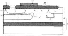
图1是部分地展示根据本发明的实施方式1的半导体器件的结构的剖面图。如图1所示,根据该实施方式1的半导体器件具有SOI衬底4、在该SOI衬底4上形成的p沟道型的MOS晶体管20。SOI衬底4具有半导体衬底1、在该半导体衬底1上形成的绝缘膜2和在该绝缘膜2上形成的n-型半导体层3。半导体衬底1是例如硅衬底,绝缘膜2是例如硅氧化膜,半导体层3是例如硅层。FIG. 1 is a cross-sectional view partially showing the structure of a semiconductor device according to Embodiment Mode 1 of the present invention. As shown in FIG. 1 , the semiconductor device according to Embodiment 1 includes an
MOS晶体管20在SOI衬底4的半导体层3上形成,具有p型的源区5和漏区6。源区5和漏区6在半导体层3的上表面内互相分离地形成。漏区6由p型的补偿区6a和p型的杂质区6b构成。杂质区6b与源区5分离地形成,补偿区6a形成为从杂质区6b的源区5侧的端部延伸到源区5一侧。
在源区5的上表面内形成p+型的杂质区7,在漏区6中的杂质区6b的上表面内形成p+型的杂质区8。在杂质区7、8上分别同时形成未图示的源电极和漏电极。A p+ -
在半导体层3的上表面上,避开杂质区7、8的上表面,形成场氧化膜10,其中的源区5和漏区6之间的半导体层3上形成的部分用作MOS晶体管20的栅绝缘膜。然后,在用作栅绝缘膜的场氧化膜10上,从俯视图上看,形成MOS晶体管20的栅电极11,使其覆盖源区5的漏区6侧的端部和补偿区6a的源区5侧的端部。场氧化膜10为例如膜厚≥200nm的硅氧化膜,栅电极11为例如掺杂的多晶硅膜和钨硅化物膜的层叠膜。On the upper surface of the
根据本实施方式1的半导体器件还具有在半导体层3内形成的杂质浓度比该半导体层3高的n型的杂质区9。杂质区9在源区5的正下方与该源区5分离地在其底部的全部区域上形成。换言之,从仰视图上看,杂质区9形成为覆盖源区5的底部的全部区域。而且,杂质区9延伸到源区5和漏区6之间的半导体层3的正下方,存在于在源区5和漏区6之间形成的MOS晶体管20的沟道区的正下方。因此,在杂质区9的全部区域上,杂质浓度的峰值的位置9a(以下称为“浓度峰位置9a”)存在于源区5的最下端5a的下方。The semiconductor device according to Embodiment 1 further includes n-
在具有以上的结构的根据本实施方式1的半导体器件中,在MOS晶体管20的源区5和漏区6之间施加电压使得源区5一侧为高电位,在栅电极11上施加负的栅电位。而且,为了使器件特性稳定,把SOI衬底4的内面的电位即半导体衬底1的电位设定为与漏区6的电位相同的值。由此,在源区5和漏区6之间的半导体层3上形成沟道层,使MOS晶体管20成为接通状态,在源区5和漏区6之间流过电流,MOS晶体管20用作半导体开关。In the semiconductor device according to Embodiment 1 having the above structure, a voltage is applied between the
另外,根据本实施方式1的半导体器件中,由于用作MOS晶体管20的栅绝缘膜的场氧化膜10的膜厚设定为≥200nm,所以可以在栅电极11上施加绝对值≥100V的高电位。因此,根据本实施方式1的半导体器件可以在例如等离子体显示屏(PDP)中的扫描驱动IC中使用。In addition, in the semiconductor device according to Embodiment 1, since the film thickness of the
下面,说明图1所示的根据本实施方式1的半导体器件的制造方法。图2~9是以工序顺序展示根据本实施方式1的半导体器件的制造方法的剖面图。如图2所示,首先形成SOI衬底4。此时的SOI衬底4的半导体层3的厚度是完成后的半导体层3的厚度的一半。本例中,完成后的半导体层3的厚度设定为例如5μm,所以此时的半导体层3的厚度设定为2.5μm。另外,半导体层3的杂质浓度设定为例如2.0×10¹⁵个离子/cm3。Next, a method of manufacturing the semiconductor device according to Embodiment 1 shown in FIG. 1 will be described. 2 to 9 are cross-sectional views showing the manufacturing method of the semiconductor device according to the first embodiment in order of steps. As shown in FIG. 2, an
然后,如图3所示,在半导体层3上形成具有预定的开口图形的光刻胶100。然后用光刻胶100作为掩模,向露出的半导体层3的上表面内离子注入磷等的n型的杂质200,除去用作掩模的光刻胶100。此时,例如,注入能量设定为50keV左右,注入量设定为5.0×10¹²个离子/cm2左右。由此,在半导体层3的上表面内有选择地形成杂质区9。另外,该杂质区9在后面的热处理工序中被扩散。Then, as shown in FIG. 3 , a
然后如图4所示,用外延生长法使半导体层3的厚度加厚到5.0μm。由此,杂质区9不从半导体层3的上表面露出而是埋入到该半导体层3中。之后,如图5所示,在半导体层3上形成具有预定的开口图形的光刻胶110。然后用光刻胶110作为掩模,向露出的半导体层3的上表面内离子注入硼等的p型的杂质210,除去用作掩模的光刻胶110。此时,例如,注入能量设定为100keV左右,注入量设定为3.0×10¹²个离子/cm2左右。由此,在半导体层3的上表面内有选择地形成补偿区6a。另外,该补偿区6a在后面的热处理工序中被扩散。Then, as shown in FIG. 4, the thickness of the
然后,如图6所示,使半导体层3的上表面有选择地热氧化,在半导体层3的上表面上形成还用作MOS晶体管20的栅绝缘膜的场氧化膜10.此时,场氧化膜10的膜厚设定成例如500nm左右.另外,在此时的热氧化中,补偿区6a和杂质区9被扩散,由此完成补偿区6a和杂质区9.扩散后的杂质区9的杂质浓度为5.0×10¹⁶个离子/cm3左右,比半导体层3的杂质浓度高。Then, as shown in FIG. 6, the upper surface of the
然后,如图7所示,在场氧化膜10上形成具有预定的开口图形的光刻胶120。然后用光刻胶120作为掩模,向露出的半导体层3的上表面内离子注入硼等的p型的杂质210,除去用作掩模的光刻胶120。此时,例如,注入能量设定为300keV左右,注入量设定为2.0×10¹²个离子/cm2左右。由此,在半导体层3的上表面内有选择地形成源区5和漏区6的杂质区6b。然后,通过例如800℃下30分钟左右的热处理,如图8所示,扩散完成源区5的杂质区6b。Then, as shown in FIG. 7 , a
然后,如图9所示,在场氧化膜10中的位于源区5和漏区6之间的半导体层3上的区域上有选择地形成MOS晶体管20的栅电极11。然后在半导体层3的上表面内离子注入硼等的p型的杂质,分别在源区5的上表面内形成杂质区7,在漏区6中的杂质区6b的上表面内形成杂质区8。此时,注入能量设定为例如,50keV左右,注入量设定为例如1.0×10¹⁴个离子/cm2左右。然后,通过800℃左右的热处理使杂质区7、8扩散,形成未图示的层间绝缘膜、漏电极、源电极、金属布线等。由此完成图1所示的半导体器件。Then, as shown in FIG. 9 ,
如以上所述,根据本实施方式1的半导体器件,杂质浓度比半导体层3高的杂质区9,在源区5的正下方在该源区5的底部的全部区域上形成,且在源区5和漏区6之间的半导体层3的正下方形成。由此,即使在为了实现器件特性的稳定化而把漏区6的电位和SOI衬底4的内面电位设定为相同时,耗尽层也难以延伸到源区5且也难以延伸到源区5和漏区6之间的半导体层3。因此,可以抑制MOS晶体管20的源区5和漏区6之间的击穿的发生,提高它们之间的耐压。As described above, according to the semiconductor device of the first embodiment, the
而且,在本实施方式1中,由于在源区5和漏区6之间的半导体层3的上表面的正下方,杂质区9的浓度峰值位置9a设定在源区5的最下端5a的下方,可以抑制MOS晶体管20的形成沟道层的区域中的n型的杂质浓度的上升。因此,可以抑制MOS晶体管20的阈值电压的上升。Furthermore, in Embodiment Mode 1, the
下面,一边与图10~12所示的半导体器件比较,一边详细说明根据本实施方式1的半导体器件的电气特性。图10~12所示的器件分别称为第1、第2和第3比较对象器件。Next, electrical characteristics of the semiconductor device according to Embodiment 1 will be described in detail while comparing with the semiconductor device shown in FIGS. 10 to 12 . The devices shown in FIGS. 10 to 12 are referred to as the first, second, and third comparison object devices, respectively.
如图10所示,第1比较对象器件是在根据本实施方式1的半导体器件中,取代SOI衬底4而具有p-型的半导体衬底21,且未形成杂质区9,MOS晶体管20形成在半导体衬底21上。在半导体衬底21的上表面内形成n-型的杂质区23,MOS晶体管20的源区5和漏区6在该杂质区23的上表面内形成。另外,在杂质区23的底部形成n+型的埋入杂质区22。As shown in FIG. 10, the first comparison target device is a semiconductor device according to the first embodiment, which has a p- type semiconductor substrate 21 instead of the
如图11所示,第2比较对象器件是在根据本实施方式1的半导体器件中,未形成杂质区9。As shown in FIG. 11 , the second comparison object device is the semiconductor device according to Embodiment 1 in which
如图12所示,第3比较对象器件是在第2比较对象器件中,还具有杂质浓度比半导体层3高的n型的杂质区19.杂质区19在半导体层3的上表面内形成,源区5在杂质区19的上表面内形成.而且,在源区5和漏区6之间的半导体层3的上表面的正下方,杂质区19中的杂质浓度的峰值的位置19a设定在源区5的最下端5a的上方.即,杂质区19中的杂质浓度的峰值存在于源区5和漏区6之间.As shown in FIG. 12 , the third comparison object device has an n-
图13、14是分别展示根据本实施方式1的半导体器件和第2比较对象器件中的电位分布的剖面图。在图13、14中展示了在MOS晶体管20的源区5和漏区6上分别施加接地电位和负的电位,并把漏区6的电位和SOI衬底4的内面电位设定成相同电位时的电位分布。在图13、14中,示出了在图1、11中未图示的源电极25、漏电极26和层间绝缘膜30。另外,在图13、14中,分别改变构成要素间的尺寸比例来展示图1、11中所示的器件。13 and 14 are cross-sectional views showing potential distributions in the semiconductor device according to Embodiment 1 and the second comparison object device, respectively. 13 and 14 show that a ground potential and a negative potential are respectively applied to the
如图13的等电位线50所示,在根据本实施方式1的半导体器件中,电场集中在漏区6的源区5侧的端部附近。这是因为,通过设置杂质区9抑制了耗尽层的延伸,充分地确保了MOS晶体管20的源漏间的耐压。As shown by the
另一方面,在第2比较对象器件中,如图14的等电位线51所示,在漏区6的源区5侧的端部附近几乎没有电场的集中。这是因为,由于场板效应,源区5和漏区6之间的半导体层3被耗尽化,耗尽层到达源区5,在MOS晶体管20的源区5和漏区6之间发生击穿。On the other hand, in the second comparison object device, as shown by the equipotential line 51 in FIG. 14 , there is almost no electric field concentration near the end of the
这样,从图13、14所示的电位分布还可以理解,在根据本实施方式1的半导体器件中,MOS晶体管20的源漏间的耐压提高了。As can be understood from the potential distributions shown in FIGS. 13 and 14 in this way, in the semiconductor device according to Embodiment 1, the withstand voltage between the source and drain of the
图15是展示MOS晶体管20中的漏电位Vd和漏电流Id的关系的图,图16是展示MOS晶体管20中的栅电位Vg和漏电流Id的关系的图。图15、16中的黑圆点表示第1比较对象器件的数据,黑三角表示第2比较对象器件的数据,白圆圈表示第3比较对象器件的数据,星号表示根据本实施方式1的半导体器件的数据。FIG. 15 is a graph showing the relationship between the drain potential Vd and the drain current Id in the
如图15所示,MOS晶体管20的源漏间的耐压,在第1比较对象器件中是约75V,在第2比较对象器件中是约25V,在第3比较对象器件中是约150V,在根据本实施方式1的半导体器件中是约180V。因此,从该实验结果还可以理解,在根据本实施方式1的半导体器件中,MOS晶体管20的源漏间的耐压提高了。As shown in FIG. 15 , the withstand voltage between the source and drain of the
另外,如图16所示,在第3比较对象器件中,通过设置杂质区19提高了MOS晶体管20的形成沟道层的区域的n型的杂质浓度,MOS晶体管20的阈值电压为约30V,但根据本实施方式1的半导体器件的阈值电压与第1和第2比较对象器件同等,为约5V。In addition, as shown in FIG. 16, in the third comparison object device, the n-type impurity concentration of the region forming the channel layer of the
如以上所述,在根据本实施方式1的半导体器件中,由于可以抑制MOS晶体管20的阈值电压的上升且提高源漏间的耐压,所以本半导体器件适合用于PDP的扫描驱动IC那样的、源漏间要求高的耐压、MOS晶体管的阈值电压也要求为尽可能低的值的电路中。As described above, in the semiconductor device according to Embodiment 1, since the increase in the threshold voltage of the
另外,如图17所示,优选地,杂质区9不在漏区6的正下方形成。换言之,优选地,从平面视图上看,杂质区9不是与漏区6重合地形成。In addition, as shown in FIG. 17 , it is preferable that
如果在源区5上施加比漏区6高的电位,则在杂质区9上也施加比漏区6高的电位。由此,在n型的杂质区9和p型漏区6之间施加反向电压。因此,如图18所示,在杂质区9延伸到漏区6正下方时,杂质区9和漏区6的距离比较近,杂质区9和漏区6之间的耐压降低。其结果,MOS晶体管20的源漏间的耐压有可能降低。If a higher potential than that of the
如图17所示,在杂质区9不在漏区6正下方形成时,可以充分确保杂质区9和漏区6的距离,可靠地抑制杂质区9和漏区6之间的耐压降低。因此,可以可靠地抑制MOS晶体管20的源漏间的耐压降低。As shown in FIG. 17 , when the
另外,在根据本实施方式1的半导体器件中,杂质区9与源区5分离而位于其最下端5a的下方,但并非一定如此.例如,即使在杂质区9位于比图1更靠上,源区5的底部被杂质区9包围,在源区5和漏区6之间的半导体层3上也存在杂质区9的场合,只要在源区5和漏区6之间的半导体层3的上表面的正下方,杂质区9的浓度峰值位置9a设定在源区5的最下端5a的下方,就可以比第3比较对象器件更能抑制MOS晶体管20的阈值电压的上升.但是,像本实施方式1那样,与源区5分离地在其最下端5a的下方形成杂质区9时,由于可以进一步抑制源区5和漏区6之间的n型的杂质浓度的上升,所以可以更加抑制MOS晶体管20的阈值电压的上升.In addition, in the semiconductor device according to Embodiment 1, the
(实施方式2)(Embodiment 2)
图19-21是以工序顺序展示根据本发明的实施方式2的半导体器件的制造方法的剖面图。根据本实施方式2的半导体器件的制造方法,是用与根据实施方式1的制造方法不同的方法制造图1所示的半导体器件的情形。19 to 21 are cross-sectional views illustrating a method of manufacturing a semiconductor device according to
如图19所示,首先形成SOI衬底4。在此,SOI衬底4的半导体层3的厚度,与实施方式1不同,设定成与完成后的半导体层3的厚度相同,设定为例如5μm。另外,与实施方式1同样地,半导体层3的杂质浓度设定为例如2×10¹⁵个离子/cm3。As shown in FIG. 19, an
然后,如图20所示,在半导体层3上形成具有预定的开口图形的光刻胶150。然后用光刻胶150作为掩模,向露出的半导体层3的上表面内离子注入硼等的p型的杂质210,除去用作掩模的光刻胶150。此时,例如,注入能量设定为100keV左右,注入量设定为3.0×10¹²个离子/cm2左右。由此,在半导体层3的上表面内有选择地形成补偿区6a。另外,与实施方式1同样地,该补偿区6a在后面的热处理工序中被扩散。Then, as shown in FIG. 20 , a
然后,如图21所示,在半导体层3上形成具有预定的开口图形的光刻胶160。然后用光刻胶160作为掩模,向露出的半导体层3的上表面内离子注入磷等的n型的杂质200,除去用作掩模的光刻胶160。此时,例如,注入能量设定为数MeV左右,注入量设定为5.0×10¹²个离子/cm2。由此,杂质区9以不从半导体层3露出的方式埋入到其内部地形成。另外,考虑到在后面的工序中形成的源区5的扩散深度和杂质区9的扩散量,把杂质区9的浓度峰值位置9a设定在离半导体层3的上表面深≥0.5μm的位置。Then, as shown in FIG. 21 , a photoresist 160 having a predetermined pattern of openings is formed on the
然后,与实施方式1同样地,把半导体层3的上表面有选择地热氧化,在半导体层3的上表面上形成场氧化膜10。由此,补偿区6a和杂质区9扩散,得到图6所示的结构。Then, as in the first embodiment, the upper surface of the
然后,与实施方式1同样地,形成源区5和漏区6(参照图7、8),再形成栅电极11(参照图9)。然后,通过形成杂质区7、8,层间绝缘膜和漏电极等,完成图1所示的半导体器件。Then, similarly to Embodiment Mode 1,
另外,在本实施方式2中,虽然展示了在形成补偿区6a后形成杂质区9的情形,但与其相反地,在形成杂质区9后形成补偿区6a也是可以的。In addition, in the second embodiment, the case where the
如上所述,根据本实施方式2的半导体器件的制造方法中,通过在半导体层3内从其上表面导入n型的杂质,以不从半导体层3露出的方式埋入其内部而形成杂质区9。由此,与实施方式1的在半导体层3的上表面内暂时形成杂质区9(参照图3),接着在该半导体层3上再次形成半导体层3(参照图4),在半导体层3内埋入杂质区9的场合相比,还可以使制造方法简单化,降低工艺成本。As described above, in the method of manufacturing a semiconductor device according to
(实施方式3)(Embodiment 3)
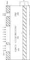
图22是展示使用了根据上述实施方式1的半导体器件的驱动电路350的结构的图.根据本实施方式3的驱动电路350,对未图示的PDP等的显示屏输出驱动电压DV,驱动该显示屏.22 is a diagram showing the configuration of a driving circuit 350 using the semiconductor device according to Embodiment 1. According to the driving circuit 350 of
如图22所示,驱动电路350具有:p沟道型的MOS晶体管301~303、n沟道型的MOS晶体管304~306、和逻辑电路307。驱动电路350具有多个图1所示的结构,该多个结构中的多个MOS晶体管20分别使用在MOS晶体管301~303中。即,MOS晶体管301~303中的每一个都是,在上述的SOI衬底4的半导体层3上形成,且具有上述的源区5和漏区6。而且在形成MOS晶体管301~303的半导体层3内,分别与MOS晶体管301~303对应地形成上述的杂质区9。因此,MOS晶体管301~303的每一个中,即使栅耐压高、阈值电压也低,且可抑制源区5和漏区6之间的击穿的发生。As shown in FIG. 22 , the drive circuit 350 includes p-channel MOS transistors 301 to 303 , n-channel MOS transistors 304 to 306 , and a logic circuit 307 . The drive circuit 350 has a plurality of structures shown in FIG. 1 , and the plurality of
另一方面,n沟道型的MOS晶体管304~306的每一个都是DMOS(双扩散的MOS)晶体管,例如,与MOS晶体管301~303同时在SOI衬底4的半导体层3上形成。On the other hand, each of the n-channel MOS transistors 304 to 306 is a DMOS (double diffused MOS) transistor, and is formed on the
在MOS晶体管301~303各自的源端子上施加≥60V的高电压VH,在MOS晶体管304~306各自的源端子上施加比高电压VH低的接地电压GND。MOS晶体管301的漏端子、MOS晶体管302和303的栅端子、与MOS晶体管304的漏端子互相连接,MOS晶体管301的栅端子、MOS晶体管302的漏端子、与MOS晶体管305的漏端子互相连接。而且,MOS晶体管303的漏端子与MOS晶体管306的漏端子互相连接。于是,逻辑电路307向MOS晶体管304~306的栅端子分别输出控制电压,对MOS晶体管304~306的每一个的接通/截止单独地控制。A high voltage VH of ≥ 60V is applied to each source terminal of the MOS transistors 301-303, and a ground voltage GND lower than the high voltage VH is applied to each source terminal of the MOS transistors 304-306. The drain terminal of MOS transistor 301, the gate terminals of MOS transistors 302 and 303, and the drain terminal of MOS transistor 304 are connected to each other, and the gate terminal of MOS transistor 301, the drain terminal of MOS transistor 302, and the drain terminal of MOS transistor 305 are connected to each other. Furthermore, the drain terminal of the MOS transistor 303 and the drain terminal of the MOS transistor 306 are connected to each other. Then, the logic circuit 307 outputs control voltages to the gate terminals of the MOS transistors 304 to 306 , and individually controls ON/OFF of each of the MOS transistors 304 to 306 .
在成为上述结构的驱动电路350中,由在高电压VH和接地电压GND之间推拉连接的MOS晶体管303、306构成输出级310,该输出级310中的MOS晶体管303、306的漏端子的电压作为驱动电压DV向显示屏输出,用该驱动电压DV驱动该显示屏。以下,详细地说明本驱动电路350的工作。In the drive circuit 350 having the above configuration, the output stage 310 is constituted by the MOS transistors 303 and 306 that are push-pull connected between the high voltage VH and the ground voltage GND, and the voltage of the drain terminals of the MOS transistors 303 and 306 in the output stage 310 is It is output to the display screen as the driving voltage DV, and the display screen is driven by the driving voltage DV. Hereinafter, the operation of the driving circuit 350 will be described in detail.
如果从逻辑电路307分别向MOS晶体管304~306的栅端子输入低电平、高电平、和高电平的信号,则MOS晶体管304~306分别成为截止状态、接通状态和接通状态。如果这样,MOS晶体管302、305的漏端子的电压A成为接地电压GND,MOS晶体管301成为接通状态。其结果,MOS晶体管301、304的漏端子的电压B成为高电压VH,MOS晶体管302成为截止状态。如果电压B为高电压VH,输出级310的高电压侧的MOS晶体管303成为截止状态。因此,MOS晶体管303、306的漏端子的电压成为接地电压GND,在例如PDP中的地址电极和维持放电电极上施加0V的驱动电压DV。When low-level, high-level, and high-level signals are input from the logic circuit 307 to the gate terminals of the MOS transistors 304-306, the MOS transistors 304-306 are turned off, on, and on, respectively. In this way, the voltage A of the drain terminals of the MOS transistors 302 and 305 becomes the ground voltage GND, and the MOS transistor 301 is turned on. As a result, the voltage B at the drain terminals of the MOS transistors 301 and 304 becomes the high voltage VH, and the MOS transistor 302 is turned off. When voltage B is high voltage VH, MOS transistor 303 on the high voltage side of output stage 310 is turned off. Therefore, the voltage at the drain terminals of the MOS transistors 303 and 306 becomes the ground voltage GND, and the drive voltage DV of 0V is applied to the address electrodes and the sustain discharge electrodes in, for example, the PDP.
另一方面,如果从逻辑电路307分别向MOS晶体管304~306的栅端子输入高电平、低电平、和低电平的信号,则MOS晶体管304~306分别成为接通状态、截止状态和截止状态。如果这样,MOS晶体管301、304的漏端子的电压B成为接地电压GND,MOS晶体管302成为接通状态。其结果,MOS晶体管302、305的漏端子的电压A成为高电压VH,MOS晶体管301成为截止状态。如果电压B为接地电压GND,输出级310的高电压侧的MOS晶体管303成为接通状态。因此,MOS晶体管303、306的漏端子的电压成为高电压VH,在例如PDP中的地址电极和维持放电电极上施加≥60V的驱动电压DV。On the other hand, if signals of high level, low level, and low level are respectively input from the logic circuit 307 to the gate terminals of the MOS transistors 304 to 306, the MOS transistors 304 to 306 are respectively turned on, off, and Deadline. In this way, the voltage B at the drain terminals of the MOS transistors 301 and 304 becomes the ground voltage GND, and the MOS transistor 302 is turned on. As a result, the voltage A at the drain terminals of the MOS transistors 302 and 305 becomes the high voltage VH, and the MOS transistor 301 is turned off. When the voltage B is the ground voltage GND, the MOS transistor 303 on the high voltage side of the output stage 310 is turned on. Therefore, the voltage at the drain terminals of the MOS transistors 303 and 306 becomes a high voltage VH, and a driving voltage DV of ≥ 60V is applied to address electrodes and sustain discharge electrodes in, for example, a PDP.
如上所述,在根据本实施方式3的驱动电路350中,输出级310的高电压侧的MOS晶体管303使用栅耐压高且阈值电压低的MOS晶体管20。As described above, in the driving circuit 350 according to
另一方面,与本实施方式3不同,输出级310的高电压侧的MOS晶体管303使用一般的栅耐压不怎么高的DMOS晶体管时,通常,在MOS晶体管303的栅端子上不能直接施加从输出级310的前级的电路输出的≥60V的高电压VH.因此,此时,必须在MOS晶体管303中的栅端子和漏端子之间插入箝位二极管,电路结构变得复杂.On the other hand, unlike the third embodiment, when a general DMOS transistor with a low gate withstand voltage is used as the MOS transistor 303 on the high voltage side of the output stage 310, usually, the gate terminal of the MOS transistor 303 cannot be directly applied from the The circuit preceding the output stage 310 outputs a high voltage VH of ≥60V. Therefore, at this time, a clamp diode must be inserted between the gate terminal and the drain terminal of the MOS transistor 303, and the circuit structure becomes complicated.
另外,与本实施方式3不同,驱动电路350具有图12所示的结构,MOS晶体管303使用图12所示的MOS晶体管20时,MOS晶体管303的耐压提高,同时其阈值电压也高,所以难以增大MOS晶体管303的输出电流。因此,图12所示的MOS晶体管20,不适合作为向显示屏输出高电压VH的输出级310的MOS晶体管303。In addition, different from the third embodiment, the drive circuit 350 has the structure shown in FIG. 12, and when the MOS transistor 303 uses the
在本实施方式3中,如上所述,由于作为输出级310的高电压侧的MOS晶体管303,使用栅耐压高且阈值电压低的MOS晶体管20,可以在该MOS晶体管303上赋予高的栅电压,且可以使该MOS晶体管303的输出电流增大。因此,即使象本实施方式3那样,在从输出级310的前级的电路输出高电压VH的栅电压时,也可以直接向MOS晶体管303的栅端子赋予该栅电压,使该驱动电路350的电路结构简单化,且可以提高MOS晶体管303的工作速度。In
(实施方式4)(Embodiment 4)
图23是展示根据本发明的实施方式4的半导体器件的结构的剖面图。如图23所示,根据本实施方式4的半导体器件具有上述的SOI衬底4。在SOI衬底4的半导体层3上形成上述的p沟道型的MOS晶体管20、NPN晶体管111、和PNP晶体管211。在半导体层3上形成贯通它的元件分离绝缘膜300,在半导体层3中用该元件分离绝缘膜300电气分离成形成MOS晶体管20的区域、形成NPN晶体管111的区域和形成PNP晶体管211的区域。元件分离绝缘膜300由例如硅氧化膜构成。23 is a cross-sectional view showing the structure of a semiconductor device according to
与实施方式1同样地,MOS晶体管20中,在源区5的上表面内形成p+型的杂质区7,在漏区6中的杂质区6b的上表面内形成p+型的杂质区8。根据本实施方式4的漏区6的补偿区6a是p-型的杂质区。在半导体层3的上表面内与源区5邻接地形成n型的杂质区12,在该杂质区12的上表面内形成n+型的杂质区13。在半导体层3中,在形成MOS晶体管20的区域上形成上述的杂质区9。根据本实施方式4的杂质区9,在源区5和杂质区12的正下方与它们的底部接触且在该底部的全部区域上形成。而且,根据本实施方式4的杂质区9延伸到源区5和漏区6之间的半导体层3的正下方,存在于在源区5和漏区6之间形成的MOS晶体管20的沟道区的正下方。而且,与实施方式1同样地,在源区5和漏区6之间的半导体层3的上表面的正下方,杂质区9中的杂质浓度的峰值的位置设定在源区5的最下端的下方。As in the first embodiment, in the
NPN晶体管111具有:与集电极106电气连接的n型的杂质区101、p型的基区103、n+型的发射区105。杂质区101和基区103在半导体层3的上表面内相互分离地形成,发射区105在基区103的上表面内形成。在杂质区101的上表面内形成n+型的杂质区102,在基区103的上表面内与发射区105分离地形成p+型的杂质区104。在半导体层3中,在形成NPN晶体管111的区域上形成杂质浓度比半导体层3高的n型的杂质区109。杂质区109与杂质区101和基区103的底部接触,且从杂质区101的正下方延伸到基区103的正下方,一直到达杂质区104的正下方。因此,在发射区105的正下方存在杂质区109。
PNP晶体管211具有:与基极206电气连接的n型的杂质区201、p+型的发射区203、p型的集电区204。杂质区201和集电区204在半导体层3的上表面内相互分离地形成,发射区203在杂质区201和集电区204之间与它们相互分离地在半导体层3的上表面内形成。在杂质区201的上表面内形成n+型的杂质区202,在集电区204的上表面内形成p+型的杂质区205。在半导体层3中,在形成PNP晶体管211的区域上形成杂质浓度比半导体层3高的n型的杂质区209。杂质区209与杂质区201底部接触,且从杂质区201的正下方延伸到发射区203的正下方,且一直延伸到发射区203和集电区204之间的半导体层3的正下方。The
在半导体层3的上表面上,避开杂质区7、8、13、102、104、202、205的上表面和发射区105、203的上表面,形成上述场氧化膜10,其中的源区5和漏区6之间的半导体层3上形成的部分用作MOS晶体管20的栅绝缘膜。然后,在用作栅绝缘膜的场氧化膜10上,从俯视图上看,形成MOS晶体管20的栅电极11,使其覆盖源区5的漏区6侧的端部和补偿区6a的源区5侧的端部。On the upper surface of the
在半导体层3的上表面上,覆盖场氧化膜10和元件分离绝缘膜300形成层间绝缘膜30。层间绝缘膜30为例如硅氧化膜。在层间绝缘膜30内形成到达杂质区8的漏电极26、和到达杂质区7和13这两者的源电极25。且在层间绝缘膜30内形成到达杂质区102的集电极106、到达发射区105的发射极107、和到达杂质区104的基极108。且在层间绝缘膜30内形成到达杂质区202的基极206、到达发射区203的发射极207、到达杂质区205的集电极208。而且,源电极25、漏电极26、集电极106和208、发射极107和207、以及基极108和206的每一个,都贯通层间绝缘膜30,还设置在该层间绝缘膜30的上表面上。On the upper surface of the
在具有以上的结构的根据本实施方式4的半导体器件中,与实施方式1同样地,在MOS晶体管20中,通过在源电极25和漏电极26之间施加预定的电压,在源区5和漏区6之间施加电压使得源区5一侧为高电位,在栅电极11上施加负的栅电位。由此,在源区5和漏区6之间的半导体层3上形成沟道层,MOS晶体管20成为接通状态,在源区5和漏区6之间流过电流,MOS晶体管20用作半导体开关。In the semiconductor device according to the fourth embodiment having the above structure, as in the first embodiment, in the
另外,半导体层3中的形成NPN晶体管111的区域和杂质区101、109用作NPN晶体管111的集电区。在集电极106和发射极107之间施加电压使得集电极106一侧为高电位,在基极108上施加正的栅电位。其结果,在集电区和发射区105之间施加电压使得该集电区一侧为高电位,在基区103上施加正的基极电位。如果这样,则如图23中的箭头AR所示,电子从发射区105向其正下方方向移动,通过基区103移动到该基区103的正下方,然后向杂质区101行进并到达杂质区101,到达集电极106。由此,在由杂质区101、半导体层3和杂质区109构成的集电区和发射区105之间流过电流,NPN晶体管111用作半导体开关。在本实施方式4中,由于至少在发射区105和基区103的正下方设置杂质浓度比半导体层3高的杂质区109,可以降低杂质区101和发射区105之间流过的电子通过的路径的电阻。由此,可以实现具有低电阻的集电区的NPN晶体管111,可以增大该NPN晶体管111的输出电流。In addition, the region where the
另外,半导体层3中的形成PNP晶体管211的区域和杂质区201、用作PNP晶体管211的基区。在发射极207和集电极208之间施加电压使得发射极207一侧为高电位,在基极206上施加负的基极电位。其结果,在发射区203和集电区204之间施加电压,使得该发射区203一侧为高电位,在由杂质区201和半导体层3构成的基区上施加负的基极电位。由此,在发射区203和集电区204之间流过电流,PNP晶体管211用作半导体开关。In addition, the region where the
本实施方式4中,MOS晶体管20的漏区6的电位、NPN晶体管111的发射区105的电位和PNP晶体管211的集电区204的电位设定成相同的值.而且,为了使器件特性稳定,把SOI衬底4的内面的电位即半导体衬底1的电位设定成与漏区6、发射区105和集电区204的电位相同的值.因此,如上述那样,虽然由于场板效应,耗尽层向源区5或源区5和漏区6之间的半导体层3延伸,但由于杂质浓度比半导体层3高的杂质区9的存在,该耗尽层难以延伸.因此,可以抑制MOS晶体管20的源区5和漏区6之间的击穿的发生,可以提高它们之间的耐压.另外,在PNP晶体管211中也是,虽然耗尽层向发射区203延伸,但由于在本实施方式4中,至少在发射区203的正下方设定了杂质浓度比半导体层3高的杂质区209,所以抑制了该耗尽层的延伸.因此,可以抑制发射区203和集电区204之间的击穿的发生,可以提高它们之间的耐压.In
另外,像本实施方式4那样,使杂质区209与杂质区201连接是优选的。此时,杂质区204的电位与在基极206上施加的基极电位大致相等。由于通常,在PNP晶体管211为截止状态时,基极电位和在发射极207上施加的发射极电位设定成相同的值,所以在PNP晶体管211为截止状态时杂质区209的电位和发射区203的电位大致相等。其结果,可以进一步抑制由场板效应导致的耗尽层的延伸。In addition, it is preferable to connect the
下面,说明图23所示的半导体器件的制造方法。图24~33是以工序顺序展示根据本实施方式4的半导体器件的制造方法的剖面图。首先,与上述的实施方式2同样地形成SOI衬底4。然后,如图24所示,在半导体层3上形成具有预定的开口图形的光刻胶500。然后用光刻胶500作为掩模,向半导体层3的上表面内离子注入磷等的n型的杂质200。此时,例如,注入能量设定为数MeV左右,注入量设定为5.0×10¹²个离子/cm2左右。由此,n型的杂质区9、109、209同时以不从半导体层3露出的方式埋入到其内部而形成。然后除去光刻胶500。另外,杂质区9、109、209在后面的热处理工序中被扩散。Next, a method of manufacturing the semiconductor device shown in FIG. 23 will be described. 24 to 33 are cross-sectional views showing the manufacturing method of the semiconductor device according to the fourth embodiment in order of steps. First, an
然后如图25所示,在半导体层3上形成具有预定的开口图形的光刻胶510。然后用光刻胶510作为掩模,向露出的半导体层3的上表面内离子注入硼等的p型的杂质210。此时,例如,注入能量设定为100keV左右,注入量设定为3.0×10¹²个离子/cm2左右。由此,在半导体层3的上表面内有选择地形成补偿区6a。然后除去光刻胶510。另外,补偿区6a在后面的热处理工序中被扩散。Then, as shown in FIG. 25 , a
然后,如图26所示,使半导体层3的上表面有选择地热氧化,在半导体层3的上表面上形成场氧化膜10。此时的热氧化中,补偿区6a和杂质区9、109、209被扩散。然后,如图27所示,在半导体层3内形成把以下区域电气分离的元件分离绝缘膜300:形成MOS晶体管20的区域、形成NPN晶体管111的区域和形成PNP晶体管211的区域。Then, as shown in FIG. 26 , the upper surface of the
然后,如图28所示,在半导体层3上形成具有预定的开口图形的光刻胶520。然后用该光刻胶520作为掩模,向露出的半导体层3的上表面内离子注入磷等的n型的杂质200。此时,例如,注入能量设定为600keV左右,注入量设定为5.0×10¹²个离子/cm2左右。由此,在半导体层3的上表面内形成杂质区12、101、201。然后除去光刻胶520。Then, as shown in FIG. 28 , a photoresist 520 having a predetermined pattern of openings is formed on the
然后,如图29所示,在半导体层3上形成具有预定的开口图形的光刻胶530。然后用光刻胶530作为掩模,向露出的半导体层3的上表面内离子注入硼等的p型的杂质210。此时,例如,注入能量设定为300keV左右,注入量设定为2.0×10¹²个离子/cm2左右。由此,在半导体层3的上表面内形成源区5、漏区6的杂质区6b、基区103和集电区204。然后除去光刻胶530,例如在800℃下进行30分钟左右的热处理,使源区5、杂质区6b、基区103和集电区204扩散。Then, as shown in FIG. 29 , a
然后,如图30所示,在场氧化膜10中的位于源区5和漏区6之间的半导体层3上的区域上有选择地形成MOS晶体管20的栅电极11。然后,如图31所示,在半导体层3上形成具有预定的开口图形的光刻胶540。然后用该光刻胶540和场氧化膜10作为掩模,向半导体层3的上表面内离子注入磷等的n型的杂质200。此时,例如,注入能量设定为50keV左右,注入量设定为2.0×10¹⁵个离子/cm2左右。由此,在杂质区12、101、201的上表面内分别形成杂质区13、102、202,在基区103的上表面内形成发射区105。然后除去光刻胶540。例如在800℃下进行30分钟左右的热处理,使杂质区13、102、202和发射区105扩散。Then, as shown in FIG. 30 ,
然后,如图32所示,在半导体层3上形成具有预定的开口图形的光刻胶550。然后用该光刻胶550和场氧化膜10作为掩模,向半导体层3的上表面内离子注入硼等的p型的杂质210。此时,例如,注入能量设定为50keV左右,注入量设定为1.0×10¹⁴个离子/cm2左右。由此,在漏区6的杂质区6b的上表面内形成杂质区8,在源区5的上表面内形成杂质区7,在基区103的上表面内形成杂质区104,在半导体层3的上表面内形成发射区203,在集电区204的上表面内形成杂质区205。然后除去光刻胶550,例如在800℃下进行30分钟左右的热处理,使杂质区7、8、104、205和发射区203扩散。Then, as shown in FIG. 32 , a
然后,在整个表面上形成层间绝缘膜30,在该层间绝缘膜30上形成具有预定的开口图形的未图示的光刻胶。然后用该光刻胶作掩模蚀刻层间绝缘膜30,除去用作掩模的光刻胶。由此,如图33所示,在层间绝缘膜30内,贯通它形成分别到达杂质区8、102、104、202、205和发射区105、203的多个接触孔430,同时形成到达杂质区7、13这两者的接触孔430。然后在整个表面上形成充填多个接触孔430的每一个的金属膜,蚀刻该金属膜。由此,形成源电极25、漏电极26、集电极106和208、发射极107和207、以及基极108和206,完成图23所示的结构。Then, an
另外,也可以为了降低电极和杂质区之间的接触电阻,使杂质区7、8、13、102、104、202、205和发射区105、203的上表面成为硅化物,在该上表面上形成钴硅化物等的硅化物。In addition, in order to reduce the contact resistance between the electrode and the impurity region, the upper surfaces of the
如上所述,在本实施方式4的半导体器件的制造方法中,由于同时形成杂质区9和杂质区109,无须增加工序数就可以形成耐压高且阈值电压低的MOS晶体管20和具有低电阻的集电区的NPN晶体管111。As described above, in the semiconductor device manufacturing method of the fourth embodiment, since the
另外,在本实施方式4中,由于同时形成杂质区9和杂质区209,无须增加工序数就可以形成耐压高且阈值电压低的MOS晶体管20和发射极和集电极间的耐压高的PNP晶体管211。In addition, in
另外,在本实施方式4中,与实施方式2同样地,通过向半导体层3的比较深的位置注入n型的杂质200,在该半导体层3内形成不从半导体层3的上表面露出的杂质区9、109、209,但是,也可以象实施方式1那样,通过在部分地形成半导体层3后,在该半导体层3的上表面附近形成杂质区9、109、209,然后用外延生长等形成半导体层3的残余部分,而不从半导体层3的上表面露出地在该半导体层3内形成杂质区9、109、209。In addition, in the fourth embodiment, as in the second embodiment, the n-
(实施方式5)(Embodiment 5)
图34是展示根据本发明的实施方式5的半导体器件的结构的剖面图。根据本实施方式5的半导体器件的结构与上述图23所示的形成MOS晶体管20的区域的结构大致相同,与图23中的该结构的不同之处仅在于取代p+型的杂质区8而具有n+型的杂质区这一点。34 is a cross-sectional view showing the structure of a semiconductor device according to
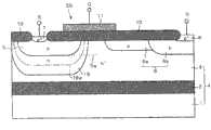
如图34所示,根据本实施方式5的半导体器件具有:上述的SOI衬底4和在该SOI衬底4上形成的p沟道型的绝缘栅型双极晶体管(以下称为“IGBT”)420。As shown in FIG. 34 , the semiconductor device according to
IGBT 420在SOI衬底4的半导体层3上形成,具有p型的发射区405、杂质区406和n+型的集电区408。发射区405和杂质区406在半导体层3的上表面内互相分离地形成。杂质区406由p型的杂质区406b和p-型的补偿区406a构成。杂质区406b与发射区405相分离地形成,补偿区406a形成为从杂质区406b的发射区405侧的端部向发射区405一侧延伸。集电区408在杂质区406b的上表面内形成。因此,集电区408和杂质区406相接触。The
在发射区405的上表面内形成p+型的杂质区407。在半导体层3的上表面内与发射区405邻接地形成n型的杂质区412。在杂质区412的上表面内形成n+型的杂质区413。A p+ -
在半导体层3的上表面上,避开集电区408和杂质区407、413的上表面,形成上述的场氧化膜10,其中的补偿区406a和发射区405之间的半导体层3上形成的部分用作IGBT 420的栅绝缘膜。然后,在用作栅绝缘膜的场氧化膜10上,从俯视图上看,形成IGBT 420的栅电极11,使其覆盖发射区405的杂质区406侧的端部和补偿区406a的发射区405侧的端部。栅电极411为例如掺杂的多晶硅膜和钨硅化物膜的层叠膜。On the upper surface of the
在半导体层3的上表面上,覆盖场氧化膜10以及栅电极411而形成有上述的层间绝缘膜30。在层间绝缘膜30内,形成有:到达集电区408的集电极426、到达杂质区407、413两者的发射极425。发射极425以及集电极426分别贯通层间绝缘膜30,也设置在该层间绝缘膜30的上表面上。On the upper surface of the
根据本实施方式5的半导体器件,与根据本实施方式1的半导体器件同样地,还具有在半导体层3内形成的杂质浓度比该半导体层3高的n型的杂质区409。The semiconductor device according to
杂质区409在发射区405的正下方与该发射区405接触且在其底部的全部区域上形成。而且,杂质区409延伸到发射区405和杂质区406之间的半导体层3的正下方,存在于在发射区405和杂质区406之间形成的IGBT 420的沟道区的正下方。因此,在杂质区409的全部区域上,杂质浓度的峰值的位置409a存在于发射区405的最下端405a的下方。The
在具有以上的结构的根据本实施方式5的半导体器件中,通过在发射极425和集电极426之间施加预定的电压,在发射区405和集电区408之间施加电压使得发射区405一侧为高电位,在栅电极411上施加负的栅电位。而且,为了使器件特性稳定,把SOI衬底4的内面的电位即半导体衬底1的电位设定为与集电区408的电位相同的值。由此,发射区405用作源,杂质区406用作漏,在发射区405和杂质区406之间的半导体层3上形成沟道层,IGBT 420成为接通状态,其结果,在发射区405和集电区408之间流过电流,IGBT 420用作半导体开关。In the semiconductor device according to
如以上所述,根据本实施方式5的半导体器件中,杂质浓度比半导体层3高的杂质区409,在发射区405的正下方在该发射区405的底部的全部区域上形成,且在发射区405和杂质区406之间的半导体层3的正下方形成。由此,即使在为了实现器件特性的稳定化而把集电区408的电位和SOI衬底4的内面电位设定为相同时,耗尽层也难以延伸到发射区405且也难以延伸到发射区405和杂质区406之间的半导体层3。因此,可以抑制用作源的发射区405和用作漏的杂质区406之间的击穿的发生,提高它们之间的耐压。As described above, in the semiconductor device according to
而且,在本实施方式5中,由于在发射区405和杂质区406之间的半导体层3的上表面的正下方,杂质区409的浓度峰值位置409a设定在发射区405的最下端405a的下方,可以抑制IGBT 420的形成沟道层的区域中的n型的杂质浓度的上升。因此,可以抑制IGBT 420的阈值电压的上升。Furthermore, in
另外,在本实施方式5中,虽然杂质区409形成为与发射区405的底部接触,但优选地,如图35所示,与发射区405分离地在其最下端405a的下方形成杂质区409。此时,由于可以进一步抑制发射区405和杂质区406之间的n型的杂质浓度的上升,所以可以更加抑制IGBT420的阈值电压的上升。In addition, in
另外,在本实施方式5中,虽然在杂质区406的正下方也存在杂质区409,但优选为,如图36所示,杂质区409不在杂质区406正下方。此时,可以充分确保杂质区409和杂质区406的距离,可靠地抑制杂质区409和杂质区406之间的耐压降低。因此,可以可靠地抑制IGBT 420的耐压降低。In the fifth embodiment, although the
另外,在根据上述实施方式3的驱动电路350中,也可以取代使用根据实施方式1的半导体器件而使用根据本实施方式5的半导体器件。例如,驱动电路350具有多个如图34所示的结构,在该多个结构中取代p沟道型的MOS晶体管301~303而分别使用多个p沟道型的IGBT 420也是可以的。由此,在对显示屏输出驱动电压DV的输出级310中,使用IGBT 420作为高电压侧的晶体管。In addition, in the drive circuit 350 according to
这样,通过作为输出级310的高电压侧的晶体管,使用栅耐压高且阈值电压低的IGBT 420,可以在该高电压侧的晶体管上赋予高的栅电压,且可以使该晶体管的输出电流增大。因此,即使像实施方式3那样,在从输出级310的前级的电路输出高电压VH的栅电压时,也可以直接向高电压侧的晶体管的栅端子赋予该栅电压,使该驱动电路350的电路结构简单化,且可以提高高电压侧的晶体管的工作速度。另外,在驱动电路350中,取代n沟道型的MOS晶体管304~306而分别使用n沟道型的IGBT也是可以的。In this way, by using the
另外,在根据上述的实施方式4的半导体器件中,也可以取代形成MOS晶体管20的区域的结构而使用根据本实施方式5的半导体器件,实现具有IGBT 420、NPN晶体管111和PNP晶体管211的半导体器件。这样的半导体器件可以用与根据实施方式4的半导体器件的制造方法大致同样的制造方法制作。以下,参照图37~43说明该半导体器件的制造方法。In addition, in the semiconductor device according to
首先,与实施方式4同样地形成SOI衬底4。然后,如图37所示,与实施方式4中的形成杂质区9、109、209时的制造方法同样地,向半导体层3的上表面内离子注入n型的杂质200,以不从半导体层3露出的方式埋入到该半导体层3内部的同时形成杂质区109、209、409。然后除去光刻胶500。First, an
然后,与实施方式4中的形成补偿区6a时的制造方法同样地,向半导体层3的上表面内离子注入p型的杂质,在半导体层3的上表面内形成补偿区406a。然后,与实施方式4的制造方法同样地,形成场氧化膜10。形成场氧化膜10时的热氧化中,如图38所示,补偿区406a和杂质区109、209、409被扩散。然后,在半导体层3内形成把以下区域电气分离的元件分离绝缘膜300:形成IGBT 420的区域、形成NPN晶体管111的区域和形成PNP晶体管211的区域。Then, similar to the manufacturing method for forming the
然后,与实施方式4中的形成杂质区12、101、201时的制造方法同样地,向半导体层3的上表面内离子注入n型的杂质,在半导体层3的上表面内形成杂质区101、201、412.然后,与实施方式4中的形成源区5、杂质区6b、基区103和集电区204时的制造方法同样地,向半导体层3的上表面内离子注入p型的杂质,在半导体层3的上表面内形成发射区405、杂质区406b、基区103和集电区204.然后,与栅电极11同样地形成栅电极411,得到图39所示的结构.Next, in the same manner as the manufacturing method for forming the
然后,如图40所示,在半导体层3上形成具有预定的开口图形的光刻胶640。然后用该光刻胶640和场氧化膜10作为掩模,用实施方式4中的形成杂质区13、102、202以及发射区105时的离子注入条件,向半导体层3的上表面内离子注入磷等的n型的杂质200。由此,在杂质区101、201、412的上表面内分别形成杂质区102、202、413,在杂质区6b的上表面内形成集电区408,在基区103的上表面内形成发射区105。然后除去光刻胶640。例如在800℃下进行30分钟左右的热处理,使杂质区102、202、413、集电区408和发射区105扩散。Then, as shown in FIG. 40 , a photoresist 640 having a predetermined pattern of openings is formed on the
然后,如图41所示,在半导体层3上形成具有预定的开口图形的光刻胶650。然后用该光刻胶650和场氧化膜10作为掩模,用实施方式4中的形成杂质区7、8、104、205和发射区203时的离子注入条件,向半导体层3的上表面内离子注入硼等的p型的杂质210。由此,在发射区405的上表面内形成杂质区407,在基区103的上表面内形成杂质区104,在半导体层3的上表面内形成发射区203,在集电区204的上表面内形成杂质区205。然后除去光刻胶650,例如在800℃下进行30分钟左右的热处理,使杂质区104、205、407和发射区203扩散。Then, as shown in FIG. 41 , a photoresist 650 having a predetermined pattern of openings is formed on the
然后,形成层间绝缘膜30,在该层间绝缘膜30内形成集电极106、208和426、发射极107、207和425、以及基极108和206。Then, an
在以上的制造方法中,通过在半导体层3内从其上表面导入n型的杂质,以不从半导体层3露出的方式埋入其内部而形成杂质区409。由此,与形成实施方式1中的杂质区9时同样地,与在半导体层3的上表面内暂时形成杂质区409,接着在该半导体层3上再次形成半导体层3,在半导体层3内埋入杂质区409的场合相比,还可以使制造方法简单化,降低工艺成本。In the above manufacturing method, the
另外,像上述制造方法那样,通过同时形成杂质区409和杂质区109,无须增加工序数就可以形成耐压高且阈值电压低的IGBT 420和具有低电阻的集电区的NPN晶体管111。Also, by simultaneously forming
另外,通过同时形成杂质区409和杂质区209,无须增加工序数就可以形成耐压高且阈值电压低的IGBT 420和发射极和集电极间的耐压高的PNP晶体管211。In addition, by simultaneously forming
Claims (14)
Applications Claiming Priority (6)
| Application Number | Priority Date | Filing Date | Title |
|---|---|---|---|
| JP2005038705 | 2005-02-16 | ||
| JP2005-038705 | 2005-02-16 | ||
| JP2005038705 | 2005-02-16 | ||
| JP2005374306AJP2006261639A (en) | 2005-02-16 | 2005-12-27 | Semiconductor device, driver circuit, and manufacturing method of semiconductor device |
| JP2005-374306 | 2005-12-27 | ||
| JP2005374306 | 2005-12-27 |
Publications (2)
| Publication Number | Publication Date |
|---|---|
| CN1822395A CN1822395A (en) | 2006-08-23 |
| CN1822395Btrue CN1822395B (en) | 2010-05-12 |
Family
ID=36814808
Family Applications (1)
| Application Number | Title | Priority Date | Filing Date |
|---|---|---|---|
| CN2006100090287AExpired - Fee RelatedCN1822395B (en) | 2005-02-16 | 2006-02-16 | Semiconductor device, driving circuit and method for manufacturing semiconductor device |
Country Status (3)
| Country | Link |
|---|---|
| US (1) | US7339236B2 (en) |
| JP (1) | JP2006261639A (en) |
| CN (1) | CN1822395B (en) |
Families Citing this family (11)
| Publication number | Priority date | Publication date | Assignee | Title |
|---|---|---|---|---|
| TW200812081A (en)* | 2006-08-30 | 2008-03-01 | Advanced Analog Technology Inc | High voltage device and manufacturing method thereof |
| JP5194594B2 (en)* | 2007-07-10 | 2013-05-08 | トヨタ自動車株式会社 | Manufacturing method of semiconductor device |
| JP5410012B2 (en)* | 2007-09-28 | 2014-02-05 | ローム株式会社 | Semiconductor device |
| US8643068B2 (en)* | 2009-03-12 | 2014-02-04 | Infineon Technologies Ag | Integrated circuit having field effect transistors and manufacturing method |
| CN102646706B (en)* | 2011-02-17 | 2014-09-24 | 立锜科技股份有限公司 | High voltage component and manufacturing method thereof |
| JP5670808B2 (en)* | 2011-04-04 | 2015-02-18 | 株式会社豊田中央研究所 | Horizontal IGBT |
| JP5734725B2 (en)* | 2011-04-27 | 2015-06-17 | ルネサスエレクトロニクス株式会社 | Semiconductor device and manufacturing method thereof |
| US8866222B2 (en) | 2012-03-07 | 2014-10-21 | Infineon Technologies Austria Ag | Charge compensation semiconductor device |
| US8901642B2 (en) | 2012-03-07 | 2014-12-02 | Infineon Technologies Austria Ag | Charge compensation semiconductor device |
| US9435833B2 (en)* | 2014-07-23 | 2016-09-06 | Freescale Semiconductor, Inc. | Resistance detection for integrated circuit driver based on parasitic inductance |
| KR102458310B1 (en) | 2018-06-19 | 2022-10-24 | 삼성전자주식회사 | Integrated circuit device |
Citations (3)
| Publication number | Priority date | Publication date | Assignee | Title |
|---|---|---|---|---|
| US5359221A (en)* | 1992-07-10 | 1994-10-25 | Hitachi, Ltd. | Semiconductor device |
| US5656844A (en)* | 1995-07-27 | 1997-08-12 | Motorola, Inc. | Semiconductor-on-insulator transistor having a doping profile for fully-depleted operation |
| US5994739A (en)* | 1990-07-02 | 1999-11-30 | Kabushiki Kaisha Toshiba | Integrated circuit device |
Family Cites Families (9)
| Publication number | Priority date | Publication date | Assignee | Title |
|---|---|---|---|---|
| JPH1187728A (en) | 1997-09-12 | 1999-03-30 | Toshiba Corp | Semiconductor device |
| JP2000252467A (en)* | 1999-03-04 | 2000-09-14 | Fuji Electric Co Ltd | High breakdown voltage horizontal semiconductor device |
| JP4929538B2 (en)* | 2001-06-29 | 2012-05-09 | 株式会社デンソー | Manufacturing method of semiconductor device |
| JP3783156B2 (en)* | 2001-10-17 | 2006-06-07 | 株式会社日立製作所 | Semiconductor device |
| JP2004172541A (en)* | 2002-11-22 | 2004-06-17 | Renesas Technology Corp | Method for manufacturing semiconductor device |
| JP3479066B2 (en) | 2002-12-09 | 2003-12-15 | シャープ株式会社 | Semiconductor device having SOI structure and method of manufacturing the same |
| JP4387291B2 (en)* | 2004-12-06 | 2009-12-16 | パナソニック株式会社 | Horizontal semiconductor device and manufacturing method thereof |
| US7973361B2 (en)* | 2005-03-30 | 2011-07-05 | Panasonic Corporation | High breakdown voltage semiconductor device and fabrication method of the same |
| KR100761825B1 (en)* | 2005-10-25 | 2007-09-28 | 삼성전자주식회사 | Horizontal MOS transistors and manufacturing method thereof |
- 2005
- 2005-12-27JPJP2005374306Apatent/JP2006261639A/enactivePending
- 2006
- 2006-02-13USUS11/352,344patent/US7339236B2/ennot_activeExpired - Fee Related
- 2006-02-16CNCN2006100090287Apatent/CN1822395B/ennot_activeExpired - Fee Related
Patent Citations (3)
| Publication number | Priority date | Publication date | Assignee | Title |
|---|---|---|---|---|
| US5994739A (en)* | 1990-07-02 | 1999-11-30 | Kabushiki Kaisha Toshiba | Integrated circuit device |
| US5359221A (en)* | 1992-07-10 | 1994-10-25 | Hitachi, Ltd. | Semiconductor device |
| US5656844A (en)* | 1995-07-27 | 1997-08-12 | Motorola, Inc. | Semiconductor-on-insulator transistor having a doping profile for fully-depleted operation |
Non-Patent Citations (2)
| Title |
|---|
| JP特开2003-197919A 2003.07.11 |
| JP特开平11-87728A 1999.03.30 |
Also Published As
| Publication number | Publication date |
|---|---|
| US20060180862A1 (en) | 2006-08-17 |
| CN1822395A (en) | 2006-08-23 |
| JP2006261639A (en) | 2006-09-28 |
| US7339236B2 (en) | 2008-03-04 |
Similar Documents
| Publication | Publication Date | Title |
|---|---|---|
| CN1822395B (en) | Semiconductor device, driving circuit and method for manufacturing semiconductor device | |
| JP5172654B2 (en) | Semiconductor device | |
| JP4037472B2 (en) | Thin epitaxial RESURF integrated circuit comprising HVp-channel and n-channel devices with sources or drains not connected to ground potential | |
| KR100710947B1 (en) | High-voltage mos transistor | |
| US6876035B2 (en) | High voltage N-LDMOS transistors having shallow trench isolation region | |
| US7906828B2 (en) | High-voltage integrated circuit device including high-voltage resistant diode | |
| JP4974474B2 (en) | Semiconductor device and manufacturing method thereof | |
| US20120049271A1 (en) | Semiconductor device with high-breakdown-voltage transistor | |
| US7173308B2 (en) | Lateral short-channel DMOS, method for manufacturing same and semiconductor device | |
| US7408234B2 (en) | Semiconductor device and method for manufacturing the same | |
| CN102254947A (en) | Semiconductor device and production method thereof | |
| JP5280142B2 (en) | Semiconductor device and manufacturing method thereof | |
| JP3354127B2 (en) | High voltage element and method of manufacturing the same | |
| CN112993038B (en) | High Voltage DMOS Transistor | |
| US7851883B2 (en) | Semiconductor device and method of manufacture thereof | |
| CN1373520A (en) | Semiconductor device and mfg. method thereof | |
| JP2007088198A (en) | Semiconductor device | |
| US8952483B2 (en) | Semiconductor device | |
| JP2003303960A (en) | Vertical mos semiconductor device and manufacturing method thereof | |
| JP5610930B2 (en) | Semiconductor device | |
| KR100370957B1 (en) | High voltage device having a polysilicon in trench and its manufacturing method | |
| JP4617688B2 (en) | Trench lateral semiconductor device and manufacturing method thereof | |
| JP4193604B2 (en) | Semiconductor device and manufacturing method thereof | |
| JP3730283B2 (en) | Manufacturing method of high voltage semiconductor device | |
| JP2010114298A (en) | High breakdown voltage semiconductor device |
Legal Events
| Date | Code | Title | Description |
|---|---|---|---|
| C06 | Publication | ||
| PB01 | Publication | ||
| C10 | Entry into substantive examination | ||
| SE01 | Entry into force of request for substantive examination | ||
| C14 | Grant of patent or utility model | ||
| GR01 | Patent grant | ||
| ASS | Succession or assignment of patent right | Owner name:NEC CORP. Free format text:FORMER OWNER: RENESAS TECHNOLOGY CORP. Effective date:20100916 | |
| C41 | Transfer of patent application or patent right or utility model | ||
| C56 | Change in the name or address of the patentee | Owner name:RENESAS ELECTRONICS Free format text:FORMER NAME: NEC CORP. | |
| COR | Change of bibliographic data | Free format text:CORRECT: ADDRESS; FROM: TOKYO, JAPAN TO: KANAGAWA, JAPAN | |
| CP01 | Change in the name or title of a patent holder | Address after:Kanagawa, Japan Patentee after:Renesas Electronics Corp. Address before:Kanagawa, Japan Patentee before:NEC ELECTRONICS Corp. | |
| TR01 | Transfer of patent right | Effective date of registration:20100916 Address after:Kanagawa, Japan Patentee after:NEC ELECTRONICS Corp. Address before:Tokyo, Japan Patentee before:Renesas Technology Corp. | |
| C17 | Cessation of patent right | ||
| CF01 | Termination of patent right due to non-payment of annual fee | Granted publication date:20100512 Termination date:20140216 |