CN1820882A - Alignment guides for saws - Google Patents
Alignment guides for sawsDownload PDFInfo
- Publication number
- CN1820882A CN1820882ACNA2005100668057ACN200510066805ACN1820882ACN 1820882 ACN1820882 ACN 1820882ACN A2005100668057 ACNA2005100668057 ACN A2005100668057ACN 200510066805 ACN200510066805 ACN 200510066805ACN 1820882 ACN1820882 ACN 1820882A
- Authority
- CN
- China
- Prior art keywords
- base plate
- dial
- housing
- saw
- axis
- Prior art date
- Legal status (The legal status is an assumption and is not a legal conclusion. Google has not performed a legal analysis and makes no representation as to the accuracy of the status listed.)
- Pending
Links
- 238000005520cutting processMethods0.000claimsabstractdescription43
- 238000007639printingMethods0.000description4
- 238000005259measurementMethods0.000description3
- 229920000122acrylonitrile butadiene styrenePolymers0.000description2
- 239000000853adhesiveSubstances0.000description2
- 230000001070adhesive effectEffects0.000description2
- 238000005553drillingMethods0.000description2
- 238000005516engineering processMethods0.000description2
- 238000005530etchingMethods0.000description2
- 238000000465mouldingMethods0.000description2
- 238000005507sprayingMethods0.000description2
- DHKHKXVYLBGOIT-UHFFFAOYSA-Nacetaldehyde Diethyl AcetalNatural productsCCOC(C)OCCDHKHKXVYLBGOIT-UHFFFAOYSA-N0.000description1
- 125000002777acetyl groupChemical class[H]C([H])([H])C(*)=O0.000description1
- XECAHXYUAAWDEL-UHFFFAOYSA-Nacrylonitrile butadiene styreneChemical compoundC=CC=C.C=CC#N.C=CC1=CC=CC=C1XECAHXYUAAWDEL-UHFFFAOYSA-N0.000description1
- 239000004676acrylonitrile butadiene styreneSubstances0.000description1
- 230000005540biological transmissionEffects0.000description1
- 230000007812deficiencyEffects0.000description1
- 230000000994depressogenic effectEffects0.000description1
- 239000000463materialSubstances0.000description1
- 238000000034methodMethods0.000description1
- 230000003287optical effectEffects0.000description1
- 229920003023plasticPolymers0.000description1
- 239000004033plasticSubstances0.000description1
- 229920000515polycarbonatePolymers0.000description1
- 239000004417polycarbonateSubstances0.000description1
- 229920006324polyoxymethylenePolymers0.000description1
- 230000035945sensitivityEffects0.000description1
Images


Classifications
- B—PERFORMING OPERATIONS; TRANSPORTING
- B23—MACHINE TOOLS; METAL-WORKING NOT OTHERWISE PROVIDED FOR
- B23D—PLANING; SLOTTING; SHEARING; BROACHING; SAWING; FILING; SCRAPING; LIKE OPERATIONS FOR WORKING METAL BY REMOVING MATERIAL, NOT OTHERWISE PROVIDED FOR
- B23D59/00—Accessories specially designed for sawing machines or sawing devices
- B23D59/001—Measuring or control devices, e.g. for automatic control of work feed pressure on band saw blade
- B23D59/002—Measuring or control devices, e.g. for automatic control of work feed pressure on band saw blade for the position of the saw blade
- B23D59/003—Indicating the cutting plane on the workpiece, e.g. by projecting a laser beam
Landscapes
- Physics & Mathematics (AREA)
- Optics & Photonics (AREA)
- Engineering & Computer Science (AREA)
- Mechanical Engineering (AREA)
- Sawing (AREA)
Abstract
Description
Translated fromChinese技术领域technical field
本发明涉及一种用于电动工具的导引装置,例如,涉及一种用于锯(如圆锯)的导引装置。The present invention relates to a guide for a power tool, for example a guide for a saw such as a circular saw.
一种典型的圆锯具有一个安装在底板上的壳体。设置在壳体中的一个马达驱动一个锯刀。底板通常具有一个用以指示由锯条限定的切割平面的槽口。为了准确地进行切割,操作者通常要在工件上划线并且在切割时使槽口与所划的线对准。除了额外的划线步骤以外,该方法还包括在切割的同时,操作者要使眼睛注视所述槽口,从而在切割长度较长时,会导致操作者疲劳并可能会出现差错。A typical circular saw has a housing mounted on a base plate. A motor disposed in the housing drives a saw blade. The shoe usually has a notch to indicate the cutting plane defined by the blade. To make an accurate cut, the operator typically scores a line on the workpiece and aligns the notch with the scribed line while cutting. In addition to the extra scribing step, the method involves keeping the operator's eye on the notches while cutting, causing operator fatigue and potential for error when cutting longer lengths.
为了解决这一问题,已研发出了带有激光对准导引装置的圆锯,以便在切割期间,实现更精确的运动。但是,这些导引装置通常固定在一上部刀片防护罩上并沿切割面射出一条激光谱线。对于希望以距离基准线具有规定的偏移距离进行切割的操作者而言,首先要求操作者划出一条平行于基准线的线,并随后进行切割。To solve this problem, circular saws have been developed with laser alignment guides for more precise movement during cutting. However, these guides are usually affixed to an upper blade guard and project a laser line along the cutting plane. For an operator wishing to cut with a prescribed offset distance from the reference line, the operator is first required to draw a line parallel to the reference line and then make the cut.
Olstowski的U.S.专利5,461,790披露了一种用于圆锯的激光导引装置,其具有一个可转动的盘,该盘允许操作者能够改变激光导引装置相对于切割平面的角度方位。但是,由于所述可转动的盘可以沿上部刀片防护罩中的调节槽滑动,因此,这种可转动盘的使用每当调节一个偏移距离或盘沿所述槽滑动时,均要求操作者测量投射的激光谱线与刀片的距离。另外,由于激光导引装置是安装在上部刀片防护罩上的,因此,难以改进带有这种激光导引装置的现存圆锯。另外,在切割时,在圆锯上的激光导引装置的位置可能会与工件或其它部件发生干涉。U.S. Patent 5,461,790 to Olstowski discloses a laser guide for a circular saw having a rotatable disc that allows the operator to change the angular orientation of the laser guide relative to the cutting plane. However, since the rotatable disc can slide along the adjustment slot in the upper blade guard, the use of such a rotatable disc requires the operator to switch every time an offset is adjusted or the disc slides along the slot. Measure the distance of the projected laser line from the blade. Additionally, since the laser guide is mounted on the upper blade guard, it is difficult to retrofit existing circular saws with such a laser guide. Additionally, the position of the laser guide on the circular saw may interfere with the workpiece or other components while cutting.
因此,本发明的方案提供了一种用于电动工具的对准导引装置。可以采用整体方式将对准导引装置固定在锯的底板或壳体上,或者可以将其作为附件来固定。由于固定了对准导引装置的转动轴线和底板之间的竖直距离,因此,可以在一刻度盘或表盘上设置直接对应水平偏移距离的刻度。从而允许进行快速调节并省略了操作者确定角度调节和规定偏移距离之间关系的需求。Therefore, the solution of the present invention provides an alignment guide for a power tool. The alignment guide can be attached integrally to the base plate or housing of the saw, or it can be attached as an accessory. Since the vertical distance between the rotation axis of the alignment guide device and the bottom plate is fixed, a scale directly corresponding to the horizontal offset distance can be provided on a dial or dial. This allows quick adjustments and eliminates the need for an operator to determine the relationship between angular adjustments and specified offset distances.
根据本发明的一个方面,一种锯包括:一个壳体,一个马达,一个锯刀,一块底板以及一个对准装置。马达至少局部设置在壳体内。锯刀由马达驱动并限定了一个切割面。底板支承壳体。对准装置固定在底板上。对准装置具有一个激光器,一个刻度盘,和一个指示器。激光器可选择地转动并绕第一轴线,在一激光平面中投射一激光束。刻度盘绕第一轴线设置并具有多个第一刻度。指示器与刻度盘对准并指示沿底板、在切割平面和激光平面之间的水平偏移距离。According to one aspect of the present invention, a saw includes: a housing, a motor, a saw blade, a base plate and an alignment device. The motor is at least partially disposed within the housing. The saw blade is driven by a motor and defines a cutting plane. The bottom plate supports the housing. The alignment device is fixed on the base plate. The alignment device has a laser, a dial, and an indicator. The laser is selectively rotatable and about the first axis to project a laser beam in a laser plane. The scale disk is arranged around the first axis and has a plurality of first scales. The indicator aligns with the dial and indicates the horizontal offset distance along the base plate between the cutting plane and the laser plane.
根据本发明的另一个方面,固定第一轴线和底板之间的竖直距离,第一轴线与切割平面大致平行。According to another aspect of the invention, the vertical distance between the first axis and the bottom plate is fixed, the first axis being substantially parallel to the cutting plane.
本发明的另一个方面提供了一块底板,该底板支承壳体以便壳体可绕转第一轴线转动。激光器可选择地转动并且绕第二轴线在激光平面内投射一激光束。固定第二轴线和底板之间的竖直距离,第二轴线与切割平面大致平行。刻度盘绕第二轴线设置并且具有多个第一刻度。指示器与刻度盘对准并指示沿底板、切割平面和激光平面之间的水平偏移距离。Another aspect of the invention provides a base plate supporting the housing so that the housing is rotatable about a first axis of rotation. The laser is selectively rotatable and projects a laser beam in the laser plane about the second axis. A vertical distance between the second axis and the base plate is fixed, the second axis being substantially parallel to the cutting plane. The scale disk is disposed about the second axis and has a plurality of first graduations. The indicator aligns with the dial and indicates the horizontal offset distance along the base plate, between the cutting plane and the laser plane.
附图说明Description of drawings
图1为安装在圆锯上所示的本发明的对准导引装置的透视图。Figure 1 is a perspective view of the alignment guide of the present invention shown mounted on a circular saw.
图1A为本发明的对准导引装置的详细视图。Figure 1A is a detailed view of the alignment guide of the present invention.
图2为安装在圆锯上所示的本发明的对准导引装置的正视图。Figure 2 is a front view of the alignment guide of the present invention shown mounted on a circular saw.
图3为安装在圆锯上所示的本发明的对准导引装置的侧视图。Figure 3 is a side view of the alignment guide of the present invention shown mounted on a circular saw.
图4为安装在圆锯上所示的本发明的对准导引装置的顶视图。Figure 4 is a top view of the alignment guide of the present invention shown mounted on a circular saw.
图5为安装在圆锯上所示的本发明的对准导引装置的另一实施例的透视图。Figure 5 is a perspective view of another embodiment of the alignment guide of the present invention shown mounted on a circular saw.
图6为安装在圆锯上所示的图5所示的对准导引装置的另一实施例的正视图。6 is a front view of another embodiment of the alignment guide shown in FIG. 5 mounted on a circular saw.
图7为正视图,其显示了以45度斜角安装在圆锯上所示的图5所示的本发明的对准导引装置。Figure 7 is a front view showing the alignment guide of the present invention shown in Figure 5 mounted on a circular saw at a 45 degree bevel.
图8为图5中所示的本发明的对准导引装置的详细视图。FIG. 8 is a detailed view of the alignment guide of the present invention shown in FIG. 5 .
图9为透视图,其显示了安装在细锯上的本发明的对准导引装置的另一实施例。Figure 9 is a perspective view showing another embodiment of the alignment guide of the present invention mounted on a fine saw.
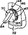
图9A为图9所示的对准导引装置的详细视图。9A is a detailed view of the alignment guide shown in FIG. 9 .
图10为图9所示的对准导引装置的侧视图。FIG. 10 is a side view of the alignment guide shown in FIG. 9 .
图11为图9所示的对准导引装置的正视图。FIG. 11 is a front view of the alignment guide shown in FIG. 9 .
详细说明Detailed description
参见图1~4,本发明的对准导引装置30如图所示,安装在圆锯10上。圆锯10包括一个安装在底板20上的壳体12。壳体12具有一个手柄13和一个扳机14。扳机14起动一个设置在壳体12内的马达16。马达16使一位于切割平面18中的锯刀17转动,以对工件100进行切割。如图1所示,圆锯10还具有一个斜角调节装置22,其允许壳体12和锯17相对于底板20通常转动1~51.5度。底板20具有一个刀片导引槽口22,在将斜角设定为0度时,该槽22与切割平面18共面。这种圆锯的例子包括可由美国南卡罗来纳州的OneWorld Technologies,Inc.of Anderson购得的RyobiModel CSB131 71/4英寸12Amp Circular Saw或RyobiModel R10631k 18 VoltCordless Circular Saw,以及可由美国的Sears,Roebuck,and Co.ofHoffman Estates,IIIinois购得的CraftsmanModel 11426 5 1/2英寸19.2Volt Cordless Trim Saw或CraftsmanModel 11516 5 1/2英寸19.2Volt Cordless Trim Saw。Referring to FIGS. 1-4, the
参见图1~4,对准导引装置30包括一个支承体21、一个激光器壳体34、一个激光发生器36、一个表盘44以及一个指示器48。虽然可以通过螺钉或螺栓(未示出)将支承体32固定至底板20上,但是,也可采用将这两个部件连接在一起的其它方式,如粘结剂、卡扣或过盈配合等。作为可选择的方案,可以使支承体22与底板20形成一体。如图1A和3所示,激光器壳体34可转动地固定在支承体32上并且可调节地绕转动轴线42转动。虽然支承体32、激光器壳体34以及表盘44可由如聚碳酸酯、缩醛或ABS(丙烯腈-丁二烯-苯乙烯三元共聚物)这样适当的塑料模制而成,但是,也可使用其它材料。Referring to FIGS. 1-4 , the
将激光发生器36设置在激光器壳体34内。激光发生器36可采用市场上可购得的激光发生器,这些激光发生器应能产生在工件100上投射激光谱线40的平面扇形光束38。作为可选择的方案,激光发生器36可分别由一个市场上可购得的激光二极管(未示出),一个准直透镜(未示出)以及一个如圆柱形透镜、不透明狭缝或全息光学元件38这样的光学元件(未示出)组装而成。将激光发生器36固定至激光器壳体34上,以便平面光束38与转动轴线42共面。利用固定螺钉(未示出),可调节地将激光发生器36固定至激光器壳体34上。作为可选择的方案,为了更易于激光发生器36的固定,可使用其它已知的固定设备。例如,可使用一个可转动的手柄或一具有杆的凸轮或适于固定激光发生器40的其它设备。另外,可以通过粘结剂或卡扣、过盈配合等,永久性地将激光发生器36固定至激光器壳体34上。A
可根据需要,通过内部电池(未示出)或外部电源对激光发生器36供电。作为可选择的方案,可直接由交流电或通过与圆锯10的电力系统相连的电缆对激光发生器36供电。如已知的那样,如果使用了交流电AC,则可采用一个AC-DC转换器以及降压器。电源开关(未示出)允许从电池或其它电源供电,以便驱动激光发生器36。该开关可一体形成在扳机14内,从而在局部压下扳机14时,起动对激光发生器36供电。作为可选择的方案,可采用一个独立开关来单独控制对激光发生器36供电。
表盘44可转动地与激光发生器36结合,从而绕转动轴线42转动。表盘44具有一个刻度盘46,该刻度盘可包括一系列标号刻度47,这些刻度沿表盘44的外周以轴向布置。在支承体32上设置一个指示器48,以指示表盘44的激光器壳体34的转动度数。指示器48可采用印刷、喷涂、打印、划刻、钻、切、刻蚀、冲压、模制等方式设置在支承体32内。作为可选择的方案,指示器可以是一个安装在支承体32上的独立件(如标签)。如图2中所示,“H”表示在底板20位于工件100上时,转动轴线42与工件100顶面之间的距离。角“θ”表示由激光平面38和从转动轴线42伸出的竖直线形成的角。将沿底板20、在切割平面18和转动轴线42之间的水平距离定为“x”。将从投射的激光谱线40至切割平面18所测得的水平偏移距离定为“d”。由于支承体32相对于底板20固定了转动轴线42,因此,固定了距离“H”。如图1A所示,该固定的已知的距离允许刻度47正好对应于水平偏移距离“d”。可以将这些刻度47直接表示为水平偏移距离“d”,而不是一个角度。在对应于零偏移距离的表盘44上的零基准点处,投射的激光谱线40与锯刀17和切割平面18共面。进一步的偏移距离可由以下公式:tanθ=(d+x)/H计算出。这些偏移距离可由英寸、厘米或其它线性测量单位表示。
图5~8显示了安装在圆锯10上的对准导引装置60的另一个实施例。在图5~8所示的实施例中,支承体62与斜角调节装置24一体形成。激光器壳体64可转动地固定至支承体62上并且绕转动轴线72转动。设置在激光器壳体64内的一个激光发生器(未示出)产生能够在工件100上投射出激光谱线70的平面扇形光束68。对准导引装置60的其它方面与图1~4中所示以及上面描述的对准导引装置30相同。Another embodiment of an
在支承体62上形成第一刻度盘74。第一刻度盘74可采用印刷、喷涂、打印、划刻、钻、切、刻蚀、冲压、模制等方式设置在支承体32内,或可形成如标签这样的独立件。指示器78形成一个从激光器壳体64伸出的凸起,从而在激光器壳体64绕转动轴线72时,其能够沿第一刻度盘74滑动。对于图1~4所示的对准导引装置30而言,可以采用上述方式计算对应于偏移距离的第一刻度盘74上的径向刻度75。A
第一刻度盘74和指示器78准确地反映了具有零度倾斜角的圆锯的偏移距离。另外,如果圆锯具有与切割平面18和工件100的交点相吻合的倾斜转动轴线80,则第一刻度盘74将保持准确。但是,如图6~7所示,如果圆锯具有偏离切割平面18和工件100交点的倾斜转动轴线80,则切割平面18将会相对于导引装置60和转动轴线72偏移。这种偏移要求进行角度校正。如图5~8所示,第二刻度盘76在支承体62上与第一刻度盘74同心设置,并且径向宽度77具有对应于偏移距离“s”的角度偏移“θ1”。该角度偏移“θ1”可由以下公式计算出:The
θ1=tan-1(s/H)。θ1=tan-1(s/H).
虽然第二刻度盘76与45度偏移角对应,但是通过重新计算因倾斜转动轴线80的偏移所产生的角度偏移,可使用与其它倾斜角度对应的其它倾斜角度或辅助刻度。While the
图9~11说明了安装在细锯110上所示的对准导引装置130的另一实施例。与上述圆锯10相似,细锯110包括一个安装在底板120上的壳体112。壳体112具有一个手柄113和一个扳机114。扳机114起动一个设置在壳体112内的马达(未示出)。马达使锯刀117在切割平面118中振动,以对工件100进行切割。细锯110还可具有一个斜角调节装置,其允许壳体112和锯刀117相对于底板120通常转动0~45度。这种细锯的例子包括可由美国南卡罗来纳州的One WorldTechnologies,lnc.of Anderson购得的RyobiModel OJ1802 18.0 VoltCordless Circular Saw,以及可由美国的Sears,Roebuck,and Co.ofHoffman Estates,IIIinois购得的CraftsmanModel 11428 19.2VoltCordless Jig Saw。9-11 illustrate another embodiment of an
如图9~11所示,虽然将对准导引装置130安装在细锯壳体112上,但是,作为可选择的方案,可以将其安装在底板120上。对准导引装置130包括一个支承体(未示出)、一个激光器壳体134、一个激光发生器(未示出)、一个表盘144以及一个指示器148。可以使支承体32与壳体112形成一体。激光器壳体134和表盘144可转动地固定在壳体112上并且可调节地绕转动轴线142转动。表盘144具有一个刻度盘146,其可包括一系列标号刻度147,这些刻度沿表盘144的外周以轴向布置。指示器148设置在壳体112上,以指示表盘144和激光器壳体134的转动度数。激光发生器产生能够在工件100上投射出一条激光谱线140的平面扇现光束138。对准导引装置130的其它方面与图1~4中所示以及上面描述的对准导引装置30相同。While the
如图11所示,“H2”表示在底板120位于工件100上时,转动轴线142与工件100顶面之间的竖直距离。角“θ2”表示由激光平面138和从转动轴线142伸出的竖直线形成的角。将从投射的激光谱线140至切割平面118所测得的水平偏移距离定为“d2”。由于支承体相对于底板120固定了转动轴线142,因此,固定了距离“H2”。该固定的已知的距离允许刻度147正好对应于水平偏移距离“d2”。可以将这些刻度147直接表示为水平偏移距离“d2”,而不是一个角度。在对应于零偏移距离的表盘144上的零基准点处,投射的激光谱线140与锯刀117和切割平面118共面。进一步的偏移距离可由以下公式:tanθ2=(d2)/H2计算出。这些偏移距离可由英寸、厘米或其它线性测量单位表示。As shown in FIG. 11 , " H2 " represents the vertical distance between the rotation axis 142 and the top surface of the
在操作中,一个开关(未示出)起动激光发生器40。扇形平面激光束36、68、138从激光发生器40射出,并在工件100上形成投射激光谱线40、70、140。通过使表盘44、144或指示器78转动与以与刻度47、75、77、147指示的理想偏移距离相对应,操作者可使激光谱线40、70、140移动至锯刀17、117左或右侧的理想偏移距离处。这样便允许操作者能够以理想的偏移距离进行准确、快速的切割。In operation, a switch (not shown) activates the laser generator 40 . Fan-shaped
本发明适用于具有切割操作平面的电动工具,如圆锯、细锯、台锯、倾割锯、往复锯、带锯、刻模机、分层剪切机以及钢丝锯。虽然已参考所说明的实施例的细节对本发明进行了详细说明,但是,这些细节不应对在权利要求中限定的本发明范围构成限制。例如,虽然已利用激光发生器说明了对准导引装置,但是,也可以使用其它光源,如灯,发光二极管等。另外,对于更细的刻度而言,可以使用游标型装置。作为可选择的方案,可以使一传动装置与表盘或刻度盘和激光器壳体相结合,以允许增加转动灵敏性和允许更细刻度和调节的机械缺点。另外,对于刻度而言,可以使用其它的测量单位,如转动单位,如度或线性单位(如毫米)等。因此,前面的详细描述只是说明性的,并不是限定性的,并且应理解包括所有等同方案的以下权利要求用于限定本发明的思想和范围。The invention is applicable to electric tools with a cutting operation plane, such as circular saws, fine saws, table saws, tilting saws, reciprocating saws, band saws, die cutters, layered shears and wire saws. While the invention has been described in detail with reference to details of the illustrated embodiments, these details should not be construed as limiting the scope of the invention as defined in the claims. For example, although the alignment guide has been described using a laser generator, other light sources such as lamps, light emitting diodes, etc. could be used. Alternatively, for finer scales, a vernier type device may be used. As an option, a transmission could be integrated with the dial or dial and the laser housing to allow increased rotational sensitivity and mechanical deficiencies to allow finer graduations and adjustments. In addition, for the scale, other measurement units can be used, such as rotational units such as degrees or linear units such as millimeters. Accordingly, the foregoing detailed description is illustrative rather than restrictive, and it is to be understood that the following claims including all equivalents are intended to define the spirit and scope of the invention.
Claims (27)
Applications Claiming Priority (2)
| Application Number | Priority Date | Filing Date | Title |
|---|---|---|---|
| US11/058,930US20060179666A1 (en) | 2005-02-16 | 2005-02-16 | Alignment guide for a saw |
| US11/058,930 | 2005-02-16 |
Publications (1)
| Publication Number | Publication Date |
|---|---|
| CN1820882Atrue CN1820882A (en) | 2006-08-23 |
Family
ID=36272495
Family Applications (1)
| Application Number | Title | Priority Date | Filing Date |
|---|---|---|---|
| CNA2005100668057APendingCN1820882A (en) | 2005-02-16 | 2005-04-26 | Alignment guides for saws |
Country Status (5)
| Country | Link |
|---|---|
| US (1) | US20060179666A1 (en) |
| EP (1) | EP1693136A1 (en) |
| CN (1) | CN1820882A (en) |
| AU (1) | AU2005229766A1 (en) |
| CA (1) | CA2536733A1 (en) |
Cited By (5)
| Publication number | Priority date | Publication date | Assignee | Title |
|---|---|---|---|---|
| CN102581376A (en)* | 2011-01-14 | 2012-07-18 | 苏州宝时得电动工具有限公司 | Reciprocating cutting tool |
| CN103357956A (en)* | 2012-03-30 | 2013-10-23 | 力山工业股份有限公司 | Laser marking device for circular sawing machine |
| CN104070229A (en)* | 2013-03-26 | 2014-10-01 | 力山工业股份有限公司 | Laser marking mechanism of circular sawing machine |
| CN104249190A (en)* | 2013-06-27 | 2014-12-31 | 艾默生管道工具(上海)有限公司 | Pipeline cutter |
| CN108527480A (en)* | 2018-05-24 | 2018-09-14 | 上海艾郎风电科技发展(集团)有限公司 | Web cutter device |
Families Citing this family (13)
| Publication number | Priority date | Publication date | Assignee | Title |
|---|---|---|---|---|
| CA2568529A1 (en)* | 2004-05-28 | 2005-12-15 | Scientific Molding Corporation Ltd. | Hand-held circular saw, in particular plunge-cut saw |
| US20070017326A1 (en)* | 2005-07-20 | 2007-01-25 | One World Technologies Limited | Laser generator mounted on a fixed component of a handheld cutting device |
| US8276281B2 (en)* | 2005-09-30 | 2012-10-02 | Positec Power Tools (Suzhou) Co., Ltd. | Circular saw |
| US20070289513A1 (en)* | 2006-06-16 | 2007-12-20 | Hsin-Chin Chen | Adjusting structure of a laser indicator of a sawing machine |
| US8505217B2 (en)* | 2007-01-12 | 2013-08-13 | Sport Maska Inc. | Skate boot with improved flexibility |
| DE102008001753A1 (en)* | 2008-05-14 | 2009-11-19 | Robert Bosch Gmbh | Machine tool, in particular hand-held machine tool |
| DE102008001762A1 (en)* | 2008-05-14 | 2009-11-19 | Robert Bosch Gmbh | Machine tool, in particular hand-held machine tool |
| US8272303B2 (en)* | 2009-04-28 | 2012-09-25 | Robert Bosch Gmbh | Miter saw with cutting alignment device on a dust chute |
| US8272304B2 (en)* | 2009-04-28 | 2012-09-25 | Robert Bosch Gmbh | Miter saw with improved dust collection system |
| TWI556893B (en) | 2013-03-07 | 2016-11-11 | 力山工業股份有限公司 | Laser alignment device for circular saw |
| KR101795519B1 (en)* | 2015-07-29 | 2017-11-09 | 주식회사 아임삭 | Portable cut saw having guide laser device |
| US10875109B1 (en) | 2018-04-30 | 2020-12-29 | Kreg Enterprises, Inc. | Adaptive cutting system |
| EP3834994A1 (en)* | 2019-12-12 | 2021-06-16 | Hilti Aktiengesellschaft | Handheld working tool |
Family Cites Families (27)
| Publication number | Priority date | Publication date | Assignee | Title |
|---|---|---|---|---|
| CH323681A (en)* | 1954-04-23 | 1957-08-15 | Raimann Gmbh B | Directional lighting system on woodworking machines, e.g. B. gang saws, circular saws or the like |
| US2804689A (en)* | 1955-12-22 | 1957-09-03 | Exxon Research Engineering Co | Surveying instrument |
| US3504716A (en)* | 1966-12-28 | 1970-04-07 | Stanley Works | Power tool and guide therefor |
| US4319404A (en)* | 1980-03-20 | 1982-03-16 | David C. Young | Chain saw sighting device |
| JPS6040202A (en)* | 1983-08-13 | 1985-03-02 | 松下電工株式会社 | Motorized circular saw |
| US4833782A (en)* | 1987-06-01 | 1989-05-30 | Robert E. Strauss | Saber saw tracing light |
| DE3922849A1 (en)* | 1989-07-12 | 1991-01-24 | Reich Maschf Gmbh Karl | Cutting indicator for circular hand-saw - uses laser beam to guide blade precisely around cutting pattern |
| US5038481A (en)* | 1990-05-04 | 1991-08-13 | Lonnie Smith | Saber saw tracking light |
| DE4108710A1 (en)* | 1991-03-16 | 1992-09-17 | Bosch Gmbh Robert | HAND MACHINE TOOL WITH GUIDE BEAM |
| US5375495A (en)* | 1992-05-18 | 1994-12-27 | Porter-Cable Corporation | Optical alignment system for circular power saws |
| US5285708A (en)* | 1992-05-18 | 1994-02-15 | Porter-Cable Corporation | Miter saw alignment system |
| US5461790A (en)* | 1994-02-16 | 1995-10-31 | Olstowski; Franek | Circular saws with laser guides for more precise movement during cutting |
| US5419050A (en)* | 1994-03-28 | 1995-05-30 | Moore; Larry | Range adjustable laser sight for bows |
| US5495675A (en)* | 1995-03-28 | 1996-03-05 | Quarton, Inc. | Laser sight for use in archery |
| US6295738B1 (en)* | 1996-04-24 | 2001-10-02 | Joel V. Risch | Chain saw measuring device |
| US5675899A (en)* | 1996-05-28 | 1997-10-14 | Webb; James | Rotary saw with laser beam alignment |
| DE69822637T2 (en)* | 1997-07-10 | 2005-02-03 | Avos Developments Ltd., Kelston | LIGHTING DEVICE FOR POWER-OPERATED TOOLS |
| US6263584B1 (en)* | 1997-08-08 | 2001-07-24 | Barry S. Owens | Alignment apparatus and method of using same |
| US5949810A (en)* | 1997-11-10 | 1999-09-07 | Jan A. Strand | Laser guide line system with cylindrical optic element |
| US6203112B1 (en)* | 1999-05-03 | 2001-03-20 | American Standards Construction Corp. | Attachable road cutting apparatus |
| JP3874990B2 (en)* | 2000-04-18 | 2007-01-31 | 株式会社マキタ | Lighting equipment for cutting machine |
| US6438854B1 (en)* | 2000-09-15 | 2002-08-27 | Edward J. Kott, Jr. | Center line marking apparatus |
| US6497168B1 (en)* | 2000-10-06 | 2002-12-24 | Bernard I. Levine | Laser alignment system for saws with rotating blades |
| US20020069542A1 (en)* | 2000-12-08 | 2002-06-13 | Musacchia John M. | Kerf indicating system for a cutting device |
| US7096587B2 (en)* | 2001-09-07 | 2006-08-29 | Hitachi Koki Co., Ltd. | Portable circular power saw with optical alignment |
| CN2562908Y (en)* | 2002-04-23 | 2003-07-30 | 南京泉峰国际贸易有限公司 | Curve saw with laser aligning device |
| CN2561565Y (en)* | 2002-05-14 | 2003-07-23 | 南京泉峰国际贸易有限公司 | Electric annular saw with laser aligning device |
- 2005
- 2005-02-16USUS11/058,930patent/US20060179666A1/ennot_activeAbandoned
- 2005-04-26CNCNA2005100668057Apatent/CN1820882A/enactivePending
- 2005-11-04EPEP05024135Apatent/EP1693136A1/ennot_activeWithdrawn
- 2005-11-08AUAU2005229766Apatent/AU2005229766A1/ennot_activeAbandoned
- 2006
- 2006-02-15CACA002536733Apatent/CA2536733A1/ennot_activeAbandoned
Cited By (9)
| Publication number | Priority date | Publication date | Assignee | Title |
|---|---|---|---|---|
| CN102581376A (en)* | 2011-01-14 | 2012-07-18 | 苏州宝时得电动工具有限公司 | Reciprocating cutting tool |
| CN102581376B (en)* | 2011-01-14 | 2014-06-04 | 苏州宝时得电动工具有限公司 | Reciprocating cutting tool |
| CN103357956A (en)* | 2012-03-30 | 2013-10-23 | 力山工业股份有限公司 | Laser marking device for circular sawing machine |
| CN103357956B (en)* | 2012-03-30 | 2015-06-24 | 力山工业股份有限公司 | Laser marking device for circular sawing machine |
| CN104070229A (en)* | 2013-03-26 | 2014-10-01 | 力山工业股份有限公司 | Laser marking mechanism of circular sawing machine |
| CN104070229B (en)* | 2013-03-26 | 2017-03-01 | 力山工业股份有限公司 | The laser labelling mechanism of circular sawing machine |
| CN104249190A (en)* | 2013-06-27 | 2014-12-31 | 艾默生管道工具(上海)有限公司 | Pipeline cutter |
| CN104249190B (en)* | 2013-06-27 | 2018-06-01 | 艾默生管道工具(上海)有限公司 | Pipe cutter |
| CN108527480A (en)* | 2018-05-24 | 2018-09-14 | 上海艾郎风电科技发展(集团)有限公司 | Web cutter device |
Also Published As
| Publication number | Publication date |
|---|---|
| EP1693136A1 (en) | 2006-08-23 |
| AU2005229766A1 (en) | 2006-08-31 |
| US20060179666A1 (en) | 2006-08-17 |
| CA2536733A1 (en) | 2006-08-16 |
Similar Documents
| Publication | Publication Date | Title |
|---|---|---|
| CA2536733A1 (en) | Alignment guide for a saw | |
| US7926398B2 (en) | Cutter with optical alignment system | |
| EP2694238B1 (en) | Optical alignment device for a table saw | |
| EP2184126B1 (en) | Cutting machine | |
| US5375495A (en) | Optical alignment system for circular power saws | |
| CN1301186C (en) | A miter saw with a beam alignment system | |
| AU785142B2 (en) | Light beam alignment system | |
| US7454840B2 (en) | Laser marking device | |
| US6988439B2 (en) | Cutting apparatus with a light-emitting unit for alignment of a workpiece | |
| WO2002083380A1 (en) | Alignment apparatus and method of using same | |
| US20110271810A1 (en) | Table saw | |
| US20110048202A1 (en) | Saw with digital measurement device | |
| EP1765546B1 (en) | Optical alignment system for power tools | |
| US20130247737A1 (en) | Cutting indicator for circular saw | |
| US20070151432A1 (en) | Optical Alignment System for Power Tools | |
| US7493700B2 (en) | Power saw comprising a display device | |
| CN201143706Y (en) | Table tool | |
| JP5366013B2 (en) | Portable cutting machine | |
| CN102029433A (en) | Bench type tool | |
| KR20190014555A (en) | Circular sawing machine of electric driving for cutting plate | |
| CN101176999A (en) | Cutting device and laser module for use with the cutting device | |
| CA2132010A1 (en) | Cut line indicator for power cutting equipment | |
| GB2453398A (en) | Handsaw with illumination means | |
| CN102039615A (en) | Table-type tool | |
| WO2007139575A1 (en) | Light beam redirecting apparatus |
Legal Events
| Date | Code | Title | Description |
|---|---|---|---|
| C06 | Publication | ||
| PB01 | Publication | ||
| C10 | Entry into substantive examination | ||
| SE01 | Entry into force of request for substantive examination | ||
| C02 | Deemed withdrawal of patent application after publication (patent law 2001) | ||
| WD01 | Invention patent application deemed withdrawn after publication |