CN1820213A - Ultrasonic distance measure - Google Patents
Ultrasonic distance measureDownload PDFInfo
- Publication number
- CN1820213A CN1820213ACNA2005800006562ACN200580000656ACN1820213ACN 1820213 ACN1820213 ACN 1820213ACN A2005800006562 ACNA2005800006562 ACN A2005800006562ACN 200580000656 ACN200580000656 ACN 200580000656ACN 1820213 ACN1820213 ACN 1820213A
- Authority
- CN
- China
- Prior art keywords
- ultrasonic
- control voltage
- ultrasonic vibrator
- receiving
- signal
- Prior art date
- Legal status (The legal status is an assumption and is not a legal conclusion. Google has not performed a legal analysis and makes no representation as to the accuracy of the status listed.)
- Granted
Links
Images


Classifications
- G—PHYSICS
- G01—MEASURING; TESTING
- G01S—RADIO DIRECTION-FINDING; RADIO NAVIGATION; DETERMINING DISTANCE OR VELOCITY BY USE OF RADIO WAVES; LOCATING OR PRESENCE-DETECTING BY USE OF THE REFLECTION OR RERADIATION OF RADIO WAVES; ANALOGOUS ARRANGEMENTS USING OTHER WAVES
- G01S15/00—Systems using the reflection or reradiation of acoustic waves, e.g. sonar systems
- G01S15/02—Systems using the reflection or reradiation of acoustic waves, e.g. sonar systems using reflection of acoustic waves
- G01S15/06—Systems determining the position data of a target
- G01S15/08—Systems for measuring distance only
- G01S15/10—Systems for measuring distance only using transmission of interrupted, pulse-modulated waves
- G01S15/102—Systems for measuring distance only using transmission of interrupted, pulse-modulated waves using transmission of pulses having some particular characteristics
- G01S15/104—Systems for measuring distance only using transmission of interrupted, pulse-modulated waves using transmission of pulses having some particular characteristics wherein the transmitted pulses use a frequency- or phase-modulated carrier wave
- G—PHYSICS
- G01—MEASURING; TESTING
- G01F—MEASURING VOLUME, VOLUME FLOW, MASS FLOW OR LIQUID LEVEL; METERING BY VOLUME
- G01F1/00—Measuring the volume flow or mass flow of fluid or fluent solid material wherein the fluid passes through a meter in a continuous flow
- G01F1/66—Measuring the volume flow or mass flow of fluid or fluent solid material wherein the fluid passes through a meter in a continuous flow by measuring frequency, phase shift or propagation time of electromagnetic or other waves, e.g. using ultrasonic flowmeters
- G—PHYSICS
- G01—MEASURING; TESTING
- G01F—MEASURING VOLUME, VOLUME FLOW, MASS FLOW OR LIQUID LEVEL; METERING BY VOLUME
- G01F23/00—Indicating or measuring liquid level or level of fluent solid material, e.g. indicating in terms of volume or indicating by means of an alarm
- G01F23/22—Indicating or measuring liquid level or level of fluent solid material, e.g. indicating in terms of volume or indicating by means of an alarm by measuring physical variables, other than linear dimensions, pressure or weight, dependent on the level to be measured, e.g. by difference of heat transfer of steam or water
- G01F23/28—Indicating or measuring liquid level or level of fluent solid material, e.g. indicating in terms of volume or indicating by means of an alarm by measuring physical variables, other than linear dimensions, pressure or weight, dependent on the level to be measured, e.g. by difference of heat transfer of steam or water by measuring the variations of parameters of electromagnetic or acoustic waves applied directly to the liquid or fluent solid material
- G01F23/296—Acoustic waves
- G01F23/2962—Measuring transit time of reflected waves
- G—PHYSICS
- G01—MEASURING; TESTING
- G01S—RADIO DIRECTION-FINDING; RADIO NAVIGATION; DETERMINING DISTANCE OR VELOCITY BY USE OF RADIO WAVES; LOCATING OR PRESENCE-DETECTING BY USE OF THE REFLECTION OR RERADIATION OF RADIO WAVES; ANALOGOUS ARRANGEMENTS USING OTHER WAVES
- G01S7/00—Details of systems according to groups G01S13/00, G01S15/00, G01S17/00
- G01S7/52—Details of systems according to groups G01S13/00, G01S15/00, G01S17/00 of systems according to group G01S15/00
- G01S7/523—Details of pulse systems
- G01S7/526—Receivers
- G01S7/527—Extracting wanted echo signals
- G—PHYSICS
- G01—MEASURING; TESTING
- G01N—INVESTIGATING OR ANALYSING MATERIALS BY DETERMINING THEIR CHEMICAL OR PHYSICAL PROPERTIES
- G01N2291/00—Indexing codes associated with group G01N29/00
- G01N2291/02—Indexing codes associated with the analysed material
- G01N2291/028—Material parameters
- G01N2291/02836—Flow rate, liquid level
- G—PHYSICS
- G01—MEASURING; TESTING
- G01S—RADIO DIRECTION-FINDING; RADIO NAVIGATION; DETERMINING DISTANCE OR VELOCITY BY USE OF RADIO WAVES; LOCATING OR PRESENCE-DETECTING BY USE OF THE REFLECTION OR RERADIATION OF RADIO WAVES; ANALOGOUS ARRANGEMENTS USING OTHER WAVES
- G01S5/00—Position-fixing by co-ordinating two or more direction or position line determinations; Position-fixing by co-ordinating two or more distance determinations
- G01S5/18—Position-fixing by co-ordinating two or more direction or position line determinations; Position-fixing by co-ordinating two or more distance determinations using ultrasonic, sonic, or infrasonic waves
- G01S5/30—Determining absolute distances from a plurality of spaced points of known location
Landscapes
- Physics & Mathematics (AREA)
- Engineering & Computer Science (AREA)
- General Physics & Mathematics (AREA)
- Radar, Positioning & Navigation (AREA)
- Remote Sensing (AREA)
- Computer Networks & Wireless Communication (AREA)
- Acoustics & Sound (AREA)
- Electromagnetism (AREA)
- Fluid Mechanics (AREA)
- Thermal Sciences (AREA)
- Measurement Of Velocity Or Position Using Acoustic Or Ultrasonic Waves (AREA)
Abstract
Translated fromChinese
Description
Translated fromChinese技术领域technical field
本发明涉及通过测量超声波的传播时间,求出到物体的距离的超声波测距装置。另外,本发明还涉及超声波测距装置使用的超声波振动器。The present invention relates to an ultrasonic distance measuring device for obtaining the distance to an object by measuring the propagation time of ultrasonic waves. In addition, the present invention also relates to an ultrasonic vibrator used in an ultrasonic distance measuring device.
背景技术Background technique
超声波测距装置向物体发出超声波,接收物体反射的超声波,从而求出超声波的传播时间,根据传播时间求出到物体的距离。由于超声波在气体及液体中传播,所以只要知道超声波在媒体中的传播速度,就能求出到位于空中及液体中的物体的距离。The ultrasonic distance measuring device sends out ultrasonic waves to the object, receives the ultrasonic waves reflected by the object, and obtains the propagation time of the ultrasonic waves, and obtains the distance to the object according to the propagation time. Since ultrasonic waves propagate in gas and liquid, as long as the propagation speed of ultrasonic waves in the medium is known, the distance to objects in the air and in liquids can be calculated.
在超声波测距装置中,从其测量原理上说,正确测量来自物体的反射波的到达时间,至关重要。一般来说,接收的反射波的强度达到给定的检知电平时,判断检知了反射波,确定反射波的到达时刻。In the ultrasonic distance measuring device, it is very important to correctly measure the arrival time of the reflected wave from the object in terms of its measurement principle. Generally, when the intensity of the received reflected wave reaches a predetermined detection level, it is judged that the reflected wave has been detected, and the arrival time of the reflected wave is determined.
由于在媒体中传播的超声波衰减,所以接收的反射波的强度也随着到物体的距离而变。因此,按照测量的距离设定多个检知电平,在测量近距离时,使用高检知电平,测量远距离时,使用低检知电平,从而正确检知反射波的技术,已广为人知。另外,同时设定多个检知电平,正确检知接收的反射波的波形上升部分,或者实施相位与发送的超声波的波形反转等形成标记,检出标记后,检知反射波的到达的技术等,也广为人知。Due to the attenuation of ultrasonic waves propagating in the medium, the intensity of the received reflected waves also varies with the distance to the object. Therefore, the technique of correctly detecting reflected waves by setting multiple detection levels according to the distance to be measured, using a high detection level when measuring a short distance and using a low detection level when measuring a long distance, has been established. Well known. In addition, multiple detection levels are set at the same time to accurately detect the rising part of the wave form of the received reflected wave, or to form a mark by inverting the phase and wave form of the transmitted ultrasonic wave, and detect the arrival of the reflected wave after detecting the mark. technology, etc., are also widely known.
另外,在采用超声波测距装置的测量中,媒体的摇晃及周围的杂音等,对测量产生影响。为了排出这种影响,专利文献1公布了对发送的超声波进行频率调制,再对由接收的反射波构成的信号进行相关处理,从而求出超声波的传播时间的超声波测距装置。如图1所示,在该超声波测距装置中,在载波信号生成部8及调制信号发生部44中,分别生成在由脉冲串波构成的载波信号8S及周期T之间,使脉冲串波的频率在f0~f1之间变化的调制信号44S。频率调制部7,用调制信号44S频率调制载波信号8S,向发送放大器3输出。发送放大器3从调制信号发生部44接收信号后,向发送用超声波振动器38输出驱动信号3S。In addition, in the measurement using the ultrasonic distance measuring device, the shaking of the medium and the surrounding noise will affect the measurement. In order to eliminate this influence,
在驱动信号3S的作用下,由发送用超声波振动器38发送的超声波在物体17中反射,反射波到达接收用超声波振动器39。被接收用超声波振动器39接收的反射波形成的接收信号,用接收放大器4放大,成为接收信号4S。频率解调部40,将接收信号4S解调。The ultrasonic wave transmitted by the transmitting ultrasonic vibrator 38 is reflected in the
相互相关部41,将调制信号44S,从该信号的生成时刻起,按照给定的时间间隔依次延迟,求出延迟的信号和解调的接收波的相互相关函数41S。相关程度检出部43,根据相互相关函数41S,将相关度最高的延迟时间作为传播时间求出。The cross-correlation unit 41 sequentially delays the modulated signal 44S at predetermined time intervals from the generation time of the signal, and obtains a cross-correlation function 41S between the delayed signal and the demodulated received wave. The correlation degree detection unit 43 obtains the delay time with the highest correlation degree as the propagation time based on the cross-correlation function 41S.
专利文献1:特开平7-104063号公报Patent Document 1: Japanese Unexamined Patent Publication No. 7-104063
在专利文献1公布的装置中,由于使用频率被调制的超声波,所以超声波振动器必须具备某种程度的广带域。可是,由于通常使用的超声波振动器,利用压电陶瓷的共振现象产生超声波,所以从原理上说,只能在共振频率附近的窄带域产生超声波。因此,想用能够充分排除杂音的影响的广带域调制超声波的频率时,就难以在该带域的整个范围内驱动超声波振动器。In the device disclosed in
虽然也存在频率带域宽的超声波振动器,但这种超声波振动器需要很大的输出驱动,难以用电池等驱动。另外,带域变得宽广后,反而还要产生接收侧的超声波振动器容易接收杂波的问题。Although there are ultrasonic vibrators with a wide frequency band, such ultrasonic vibrators require a large output drive and are difficult to drive with a battery or the like. In addition, when the bandwidth is widened, there is a problem that the ultrasonic vibrator on the receiving side tends to receive clutter conversely.
发明内容Contents of the invention
本发明要解决现有技术的这一课题,目的在于提供可以利用简单的结构、精度很高地进行计测的超声波测距装置。The present invention solves this conventional problem, and an object of the present invention is to provide an ultrasonic distance measuring device capable of measuring with high precision with a simple structure.
本发明的超声波测距装置,包括:能够使共振频率或共鸣频率变化的发送用超声波振动器及接收用超声波振动器;为了驱动所述发送用超声波振动器、发送所述超声波,生成频率被调制的驱动信号的驱动部;生成旨在使所述发送用超声波振动器的共振频率或共鸣频率变化的控制电压,在由所述发送用超声波振动器发送所述超声波之际,将所述控制电压外加给所述发送用超声波振动器的发送用控制电压生成部;生成旨在使所述接收用超声波振动器的共振频率或共鸣频率变化的控制电压,从生成所述驱动信号起,在可调整的延迟时间后,将所述控制电压外加给所述接收用超声波振动器的接收用控制电压生成部;检出用所述接收用超声波振动器接收的超声波产生的接收信号的强度的接收部;由所述发送用超声波振动器向测量目标多次发送的超声波产生的反射波,使所述延迟时间变化后,分别用所述接收用超声波振动器接收,根据所述接收部中接收到获得强度最大的接收信号的超声波时的延迟时间,求出所述超声波的传播时间,根据所述超声波的传播时间,求出到所述测量目标的距离。The ultrasonic distance measuring device of the present invention includes: an ultrasonic vibrator for transmission and an ultrasonic vibrator for reception capable of changing the resonant frequency or the resonant frequency; in order to drive the ultrasonic vibrator for transmission and transmit the ultrasonic waves, the generation frequency is modulated A drive unit for a drive signal; generates a control voltage intended to change the resonance frequency or the resonance frequency of the ultrasonic vibrator for transmission, and when the ultrasonic wave is transmitted by the ultrasonic vibrator for transmission, the control voltage is A transmission control voltage generation unit applied to the transmission ultrasonic vibrator; generating a control voltage intended to change the resonance frequency or resonance frequency of the reception ultrasonic vibrator, and after generating the drive signal, it can be adjusted After a delay time of 20 minutes, the control voltage is applied to the receiving control voltage generating part of the receiving ultrasonic vibrator; the receiving part detects the intensity of the received signal generated by the ultrasonic wave received by the receiving ultrasonic vibrator; The reflected waves generated by the ultrasonic waves transmitted multiple times by the transmitting ultrasonic vibrator to the measurement target are respectively received by the receiving ultrasonic vibrator after changing the delay time, and the intensity is obtained according to the reception in the receiving part. The delay time when the ultrasonic wave of the signal is received is the largest, the propagation time of the ultrasonic wave is obtained, and the distance to the measurement target is obtained based on the propagation time of the ultrasonic wave.
在某种理想的实施方式中,超声波测距装置还具有:生成、输出旨在以给定的时序使所述驱动部、所述发送用控制电压生成部及所述接收用控制电压生成部动作的触发信号的时序部;所述接收用控制电压生成部,包含每逢接收所述触发后,以给定的时间间隔,生成长度不同的延迟时间的延迟部。In a certain preferred embodiment, the ultrasonic distance measuring device further includes: generating and outputting signals for operating the drive unit, the control voltage generation unit for transmission, and the control voltage generation unit for reception at a given timing. A timing unit of the trigger signal; the receiving control voltage generating unit includes a delay unit that generates delay times of different lengths at predetermined time intervals every time the trigger is received.
在某种理想的实施方式中,超声波测距装置还具有:从所述时序部接收所述触发信号,计测从接收了所述触发信号时起,到所述接收用超声波振动器接收的接收信号到达给定电平时为止的时间的传播时间预备计测部;所述接收用控制电压生成部,根据所述预备计测部计测的时间及所述时序部的触发信号,生成延迟时间。In a certain preferred embodiment, the ultrasonic distance measuring device further includes: receiving the trigger signal from the timing unit, and measuring the reception time from when the trigger signal is received to the receiving ultrasonic vibrator. A propagation time pre-measurement unit for a time until a signal reaches a predetermined level; the receiving control voltage generation unit generates a delay time based on the time measured by the pre-measurement unit and the trigger signal of the timing unit.
在某种理想的实施方式中,所述发送用控制电压生成部及所述接收用控制电压生成部,与所述驱动信号的频率的调制大体一致地生成使所述接收用超声波振动器及所述发送用超声波振动器的共振频率或共鸣频率变化的控制电压。In a certain preferred embodiment, the transmission control voltage generation unit and the reception control voltage generation unit generate the frequency of the reception ultrasonic vibrator and the reception control voltage substantially in accordance with the modulation of the frequency of the drive signal. The resonant frequency of the ultrasonic vibrator for transmission or the control voltage for changing the resonant frequency.
本发明的超声波测距装置,包括:能够使共振频率或共鸣频率变化的发送用超声波振动器及接收用超声波振动器;旨在驱动所述发送用超声波振动器、发送测量用超声波而生成的测量用驱动信号——以给定的时间间隔生成、包含频率调制的多个第1驱动信号的所述测量用驱动信号的驱动部;生成旨在使所述发送用超声波振动器的共振频率或共鸣频率变化的第1控制电压,在由所述发送用超声波振动器发送所述超声波之际,将所述控制电压外加给所述发送用超声波振动器的发送用控制电压生成部;生成旨在使所述接收用超声波振动器的共振频率或共鸣频率变化的第1控制电压,从生成各第1驱动信号起,在给定的延迟时间后,将所述第1控制电压外加给所述接收用超声波振动器的接收用控制电压生成部;检出用所述接收用超声波振动器接收的超声波产生的接收信号的强度的接收部;一边使所述时间间隔及所述延迟时间中的一方恒定,另一方变化,一边用所述接收用超声波振动器分别接收在所述第1驱动信号的作用下由所述发送用超声波振动器向测量目标发送的超声波形成的多个第1反射波;在所述接收部中,根据检出的所述第1接收信号的强度,求出所述第1超声波的传播时间,根据所述传播时间,求出到所述测量目标的距离。The ultrasonic distance measuring device of the present invention includes: a transmitting ultrasonic vibrator and a receiving ultrasonic vibrator capable of changing the resonant frequency or resonant frequency; Drive signal—a drive unit that generates the measurement drive signal at a given time interval, including a plurality of frequency-modulated first drive signals; generates a resonance frequency or resonance for the transmission ultrasonic vibrator A first control voltage whose frequency changes is applied to a transmission control voltage generation unit of the transmission ultrasonic vibrator when the ultrasonic wave is transmitted by the transmission ultrasonic vibrator; The resonant frequency of the ultrasonic vibrator for reception or the first control voltage for changing the resonant frequency is applied to the receiving control voltage after a predetermined delay time from generation of each first drive signal. a receiving control voltage generating unit of the ultrasonic vibrator; a receiving unit that detects the strength of a received signal generated by the ultrasonic wave received by the receiving ultrasonic vibrator; while keeping one of the time interval and the delay time constant, On the other hand, the receiving ultrasonic vibrator is used to respectively receive a plurality of first reflected waves formed by the ultrasonic waves transmitted by the transmitting ultrasonic vibrator to the measurement target under the action of the first driving signal; In the receiving unit, a propagation time of the first ultrasonic wave is obtained based on the detected strength of the first received signal, and a distance to the measurement target is obtained based on the propagation time.
在某种理想的实施方式中,所述时间间隔恒定,所述延迟时间变化。In an ideal implementation, the time interval is constant, and the delay time varies.
在某种理想的实施方式中,所述延迟时间恒定,所述时间间隔变化。In an ideal implementation, the delay time is constant and the time interval is variable.
在某种理想的实施方式中,所述接收部,求出所述第1接收信号的强度的延迟时间上的重心,根据所述重心,求出所述第1超声波的传播时间。In a certain preferred embodiment, the receiving unit obtains a center of gravity on a delay time of the intensity of the first received signal, and obtains a propagation time of the first ultrasonic wave based on the center of gravity.
在某种理想的实施方式中,所述接收用控制电压生成部及所述发送用控制电压生成部,与所述第1驱动信号的频率的调制大体一致地生成使所述接收用超声波振动器及所述发送用超声波振动器的共振频率或共鸣频率变化的所述第1控制电压。In a certain preferred embodiment, the receiving control voltage generating unit and the transmitting control voltage generating unit generate the receiving ultrasonic vibrator substantially in accordance with the modulation of the frequency of the first drive signal. and the resonant frequency of the transmitting ultrasonic vibrator or the first control voltage for changing the resonant frequency.
在某种理想的实施方式中,所述驱动部,生成所述第2驱动信号,以便使所述测量用驱动信号在所述第1驱动信号之前包含由第1频率向第2频率切换的第2驱动信号;所述接受用控制电压生成部,在所述第1控制电压之前,生成用所述第1频率使所述接收用超声波振动器共振或共鸣的第2控制电压;所述接收用超声波振动器,接收按照所述第2驱动信号由所述发送用超声波振动器向测量目标发送的第2超声波产生的第2反射波;所述接收部,检出第2反射波产生的第2接收信号的强度变化,根据检出结果,设定所述延迟时间。In a certain preferred embodiment, the drive unit generates the second drive signal so that the measurement drive signal includes a second frequency switching from the first frequency to the second frequency before the first drive signal. 2. a drive signal; the receiving control voltage generation unit generates a second control voltage for causing the receiving ultrasonic vibrator to resonate or resonate at the first frequency before the first control voltage; The ultrasonic vibrator receives the second reflected wave generated by the second ultrasonic wave transmitted by the transmitting ultrasonic vibrator to the measurement target according to the second driving signal; the receiving unit detects the second reflected wave generated by the second reflected wave. The intensity of the received signal changes, and the delay time is set according to the detection result.
在某种理想的实施方式中,所述驱动信号,是频率瞬变波(chirp波)。In an ideal implementation, the driving signal is a frequency transient wave (chirp wave).
在某种理想的实施方式中,所述驱动信号,是脉冲波。In an ideal implementation, the driving signal is a pulse wave.
在某种理想的实施方式中,超声波测距装置还包括计测所述测量目标的周围的环境温度的温度计,根据测量的环境温度,补偿所述超声波的传播速度,使用后的传播速度,求出到所述测量目标的距离。In an ideal embodiment, the ultrasonic distance measuring device further includes a thermometer for measuring the ambient temperature of the measurement target, and according to the measured ambient temperature, the propagation speed of the ultrasonic wave is compensated, and the propagation speed after use is calculated. The distance to the measurement target.
在某种理想的实施方式中,所述发送用超声波振动器及接收用超声波振动器,分别包括振动板、安装在所述振动板上的压电振动器、利用所述控制电压或第1控制电压使所述振动板伸缩的促动器。In a certain preferred embodiment, the ultrasonic vibrator for transmission and the ultrasonic vibrator for reception respectively include a vibrating plate, a piezoelectric vibrator mounted on the vibrating plate, controlled by the control voltage or the first Voltage causes the actuator to stretch the vibrating plate.
在某种理想的实施方式中,所述发送用超声波振动器及接收用超声波振动器,分别包括共鸣器、安装在所述共鸣器上的压电振动器、利用所述控制电压或第1控制电压使所述共鸣器的共鸣频率变化的促动器。In a certain preferred embodiment, the ultrasonic vibrator for transmission and the ultrasonic vibrator for reception respectively include a resonator, a piezoelectric vibrator mounted on the resonator, and are controlled by the control voltage or the first An actuator that changes the resonant frequency of the resonator by voltage.
在某种理想的实施方式中,所述发送用超声波振动器及接收用超声波振动器,分别包括:第1音响匹配层,压电振动器,在所述第1音响匹配层及所述压电振动器之间设置的第2音响匹配层,利用所述控制电压或第1控制电压使所述第2音响匹配层的厚度伸缩的促动器。In an ideal embodiment, the ultrasonic vibrator for transmission and the ultrasonic vibrator for reception respectively include: a first acoustic matching layer, a piezoelectric vibrator, and the first acoustic matching layer and the piezoelectric vibrator The second acoustic matching layer provided between the vibrators is an actuator that expands and contracts the thickness of the second acoustic matching layer by using the control voltage or the first control voltage.
在某种理想的实施方式中,所述第2音响匹配层是液体。In a certain preferred embodiment, the second acoustic matching layer is liquid.
本发明的方位计,具有多个上述某项规定的超声波测距装置,根据利用所述多个超声波测距装置计测的到测量目标的距离,求出所述测量目标的方位。The azimuth meter of the present invention includes a plurality of the above-mentioned ultrasonic distance measuring devices, and obtains the direction of the measurement target based on the distance to the measurement target measured by the plurality of ultrasonic distance measuring devices.
本发明的流量计,具有上述某项规定的超声波测距装置,隔着流体的流路,相对配置所述超声波测距装置的发送用超声波振动器及接收用超声波振动器,根据超声波的传播时间,求出流体的流速及流量。The flowmeter of the present invention has the ultrasonic distance measuring device specified in the above-mentioned one, and the transmitting ultrasonic vibrator and the receiving ultrasonic vibrator of the ultrasonic distance measuring device are arranged opposite to each other across the flow path of the fluid. , Find the velocity and flow rate of the fluid.
本发明的采用超声波的距离测量方法,包括:使用频率调制的驱动信号,一边使共振频率或共鸣频率与所述驱动信号的频率的调制大体一致地变化,一边驱动发送用超声波振动器,从而向测量目标发送超声波的步骤;从生成所述驱动信号起,在可调整的延迟时间后,一边使共振频率或共鸣频率变化,一边用接收用超声波振动器接收由所述测量目标获得的所述超声波产生的反射波的步骤;使所述延迟时间变化后,多次进行所述发送步骤及所述接收步骤,根据所述接收用超声波振动器中接收信号强度最大的超声波时的所述延迟时间,求出所述超声波的传播时间,根据所述传播时间,求出到所述测量目标的距离。The distance measuring method using ultrasonic waves according to the present invention includes: using a frequency-modulated driving signal, driving the ultrasonic vibrator for transmission while changing the resonance frequency or the resonance frequency substantially in accordance with the modulation of the frequency of the driving signal, thereby A step of transmitting an ultrasonic wave by the measurement target: receiving the ultrasonic wave obtained by the measurement target with a receiving ultrasonic vibrator while changing the resonance frequency or the resonance frequency after an adjustable delay time from the generation of the driving signal The step of generating reflected waves; after changing the delay time, performing the sending step and the receiving step a plurality of times, according to the delay time when the ultrasonic wave with the highest signal strength is received in the ultrasonic vibrator for receiving, The propagation time of the ultrasonic wave is obtained, and the distance to the measurement target is obtained based on the propagation time.
本发明的采用超声波的距离测量方法,包括:使用按照给定的时间间隔生成、频率被调制的多个第1驱动信号,一边使共振频率或共鸣频率与所述驱动信号的频率的调制大体一致地变化,一边驱动发送用超声波振动器,从而向测量目标发送超声波的步骤;从生成所述多个第1驱动信号起,分别在可调整的延迟时间后,一边使共振频率或共鸣频率变化,一边分别接收由所述测量目标获得的所述第1超声波产生的第1反射波的步骤;根据接收所述各第1反射波获得的多个第1接收信号的强度,求出所述第1超声波的传播时间,根据所述传播时间计算到所述测量目标的距离的步骤;所述发送步骤中的所述时间间隔及所述接收步骤中的所述延迟时间中,一方恒定,另一方变化。The distance measuring method using ultrasonic waves according to the present invention includes: using a plurality of first driving signals generated at predetermined time intervals and frequency-modulated, while making the resonance frequency or the modulation of the resonance frequency substantially coincide with the frequency of the driving signals changing, while driving the ultrasonic vibrator for transmission, so as to transmit the ultrasonic wave to the measurement target; from the generation of the plurality of first driving signals, after an adjustable delay time, the resonance frequency or the resonance frequency is changed, The step of receiving the first reflected waves generated by the first ultrasonic wave obtained by the measurement target, respectively; according to the intensity of a plurality of first received signals obtained by receiving the first reflected waves, the first The propagation time of ultrasonic waves, a step of calculating the distance to the measurement target based on the propagation time; one of the time intervals in the sending step and the delay time in the receiving step is constant and the other is variable .
在某种理想的实施方式中,所述发送步骤中的所述时间间隔变化,所述接收步骤中的所述延迟时间恒定。In an ideal implementation manner, the time interval in the sending step varies, and the delay time in the receiving step is constant.
在某种理想的实施方式中,所述发送步骤中的所述时间间隔恒定,所述接收步骤中的所述延迟时间变化。In an ideal implementation, the time interval in the sending step is constant, and the delay time in the receiving step varies.
在某种理想的实施方式中,所述计算步骤,分别检出所述第1反射波的接收强度,根据所述检出的强度,求出所述接收强度的所述延迟时间上的重心,根据重心求出所述第1超声波的传播时间。In a certain preferred embodiment, the calculation step is to detect the reception intensity of the first reflected wave respectively, and calculate the center of gravity of the delay time of the reception intensity based on the detected intensity, The propagation time of the first ultrasonic wave is obtained from the center of gravity.
在某种理想的实施方式中,采用超声波的距离测量方法,还包括:在所述发送步骤之前,生成由第1频率切换成第2频率的第2驱动信号,一边使共振频率或共鸣频率与所述第2驱动信号的频率变化大体一致地变化,一边驱动发送用超声波振动器,从而向测量目标发送第2超声波的步骤;一边用所述第1频率使所述接收用超声波振动器共振或共鸣地驱动,一边接受所述第2超声波产生的第2反射波的步骤;检出第2反射波产生的第2接收信号的强度的强度变化,根据检出结果,设定所述延迟时间。In a certain ideal embodiment, the distance measurement method using ultrasonic waves further includes: before the sending step, generating a second drive signal switched from the first frequency to the second frequency, while making the resonant frequency or the resonant frequency and a step of transmitting a second ultrasonic wave to a measurement target while driving the transmitting ultrasonic vibrator while changing the frequency of the second drive signal substantially uniformly; resonating the receiving ultrasonic vibrator at the first frequency or Resonantly driven, receiving a second reflected wave generated by the second ultrasonic wave; detecting a change in the strength of a second received signal generated by the second reflected wave, and setting the delay time based on the detection result.
采用本发明后,一边使超声波振动器的共振频率变化,一边收送频率被调制的超声波。因此,即使构成超声波振动器的压电体元件的带域狭窄,也能用宽带域收发超声波,可以不容易受到测量环境中的噪声及风等环境的摇晃等的影响,进行高精度的测量。According to the present invention, frequency-modulated ultrasonic waves are transmitted while changing the resonance frequency of the ultrasonic vibrator. Therefore, even if the band of the piezoelectric element constituting the ultrasonic vibrator is narrow, ultrasonic waves can be transmitted and received in a wide band, and it is possible to perform high-precision measurement without being affected by noise in the measurement environment and environmental fluctuations such as wind.
另外,本发明的超声波振动器,使用带域狭窄的压电体元件,利用促动器使共振频率或共鸣频率变化。因此,可以用小电力驱动压电体元件,而且能够实现现有技术中需要使用大电力驱动的在宽带域中的振动。In addition, the ultrasonic vibrator of the present invention uses a narrow-band piezoelectric element, and uses an actuator to change the resonant frequency or the resonant frequency. Therefore, it is possible to drive the piezoelectric body element with a small electric power, and it is possible to realize vibration in a wide band region which needs to be driven with a large electric power in the related art.
附图说明Description of drawings
图1是表示现有技术的超声波测距装置的结构的方框图。FIG. 1 is a block diagram showing the configuration of a conventional ultrasonic distance measuring device.
图2A是表示本发明的超声波测距装置使用的超声波振动器的俯视图。2A is a plan view showing an ultrasonic vibrator used in the ultrasonic distance measuring device of the present invention.
图2B是表示本发明的超声波测距装置使用的超声波振动器的剖面图。2B is a cross-sectional view showing an ultrasonic vibrator used in the ultrasonic distance measuring device of the present invention.
图3A是表示本发明的超声波测距装置使用的其它超声波振动器的俯视图。3A is a plan view showing another ultrasonic vibrator used in the ultrasonic distance measuring device of the present invention.
图3B是表示本发明的超声波测距装置使用的其它超声波振动器的剖面图。3B is a cross-sectional view showing another ultrasonic vibrator used in the ultrasonic distance measuring device of the present invention.
图4是表示图3所示的超声波振动器的振动特性的曲线图。FIG. 4 is a graph showing vibration characteristics of the ultrasonic vibrator shown in FIG. 3 .
图5是表示本发明的超声波测距装置使用的其它超声波振动器的剖面图。5 is a cross-sectional view showing another ultrasonic vibrator used in the ultrasonic distance measuring device of the present invention.
图6是表示图5所示的超声波振动器的振动特性的曲线图。FIG. 6 is a graph showing vibration characteristics of the ultrasonic vibrator shown in FIG. 5 .
图7是表示采用本发明的超声波测距装置的第1实施方式的结构的方框图。Fig. 7 is a block diagram showing the configuration of the first embodiment of the ultrasonic distance measuring device according to the present invention.
图8是表示图7所示的超声波测距装置的驱动部的各部生成的信号的波形的一个示例。FIG. 8 shows an example of a waveform of a signal generated by each unit of the drive unit of the ultrasonic distance measuring device shown in FIG. 7 .
图9是讲述图7所示的超声波测距装置的传播时间预备计测部中检出接收信号的图形。FIG. 9 is a diagram illustrating detection of a received signal in a propagation time preliminary measurement unit of the ultrasonic distance measuring device shown in FIG. 7 .
图10A是表示接收部中的接收信号及包络线信号的一个示例的图形。FIG. 10A is a graph showing an example of a received signal and an envelope signal in a receiving unit.
图10B是表示检出图10A的接收信号时,外加给接收用超声波振动器的控制电压的图形。FIG. 10B is a graph showing a control voltage applied to the receiving ultrasonic vibrator when the receiving signal shown in FIG. 10A is detected.
图11A是表示接收部中的接收信号及包络线信号的其它示例的图形。Fig. 11A is a graph showing another example of a received signal and an envelope signal in a receiving unit.
图10B是表示检出图11A的接收信号时,外加给接收用超声波振动器的控制电压的图形。FIG. 10B is a graph showing a control voltage applied to the receiving ultrasonic vibrator when the receiving signal shown in FIG. 11A is detected.
图12是将图10A及图11A所示的包络线信号重叠显示的图形。Fig. 12 is a graph showing the envelope signals shown in Figs. 10A and 11A superimposed on each other.
图13是表示判定部的结构的方框图。FIG. 13 is a block diagram showing the configuration of a determination unit.
图14是表示测量步骤的流程图。Fig. 14 is a flowchart showing the measurement procedure.
图15是表示图7的超声波测距装置的各部中的信号的时序图的一个示例。FIG. 15 is an example of a timing chart showing signals in each unit of the ultrasonic distance measuring device of FIG. 7 .
图16是表示图7的超声波测距装置的各部中的信号的时序图的其它示例。FIG. 16 is another example of a timing chart showing signals in each unit of the ultrasonic distance measuring device of FIG. 7 .
图17是表示图7的超声波测距装置的各部中的信号的时序图的其它示例。FIG. 17 is another example of a timing chart showing signals in each unit of the ultrasonic distance measuring device of FIG. 7 .
图18是表示图7的超声波测距装置的各部中的信号的时序图的其它示例。FIG. 18 is another example of a timing chart showing signals in each unit of the ultrasonic distance measuring device of FIG. 7 .
图19是讲述使用本发明的超声波测距装置的方位计的图形。Fig. 19 is a diagram illustrating an azimuth meter using the ultrasonic distance measuring device of the present invention.
图20是表示采用本发明的超声波测距装置的第2实施方式的结构的方框图。Fig. 20 is a block diagram showing the configuration of a second embodiment of an ultrasonic distance measuring device according to the present invention.
图21是表示图20所示的超声波测距装置的各部中的信号的时序图。FIG. 21 is a timing chart showing signals in each unit of the ultrasonic distance measuring device shown in FIG. 20 .
图22示出图20的超声波测距装置的发送放大器输出的信号的波形。FIG. 22 shows a waveform of a signal output from a transmission amplifier of the ultrasonic distance measuring device in FIG. 20 .
图23A示出外加给接收用超声波振动器的促动器的一种DC控制电压波形。Fig. 23A shows a DC control voltage waveform applied to the actuator of the ultrasonic vibrator for reception.
图23B示出外加给接收用超声波振动器的促动器的另一种DC控制电压波形。Fig. 23B shows another DC control voltage waveform applied to the actuator of the receiving ultrasonic vibrator.
图23C示出外加给接收用超声波振动器的促动器的另一种DC控制电压波形。Fig. 23C shows another DC control voltage waveform applied to the actuator of the ultrasonic vibrator for reception.
图24A示出图20的超声波测距装置的接收部中检出的接收信号及其峰值保持信号。FIG. 24A shows received signals and their peak hold signals detected by the receiving unit of the ultrasonic distance measuring device in FIG. 20 .
图24B示出图20的超声波测距装置的接收部中检出的接收信号及其包络线检波信号。FIG. 24B shows a received signal and its envelope detection signal detected by the receiving unit of the ultrasonic distance measuring device in FIG. 20 .
图25是表示第2C-D变换器的输出值的分布的曲线图。Fig. 25 is a graph showing the distribution of output values of the second C-D converter.
图26示出图20的超声波测距装置的发送放大器输出的信号的其它波形。FIG. 26 shows other waveforms of signals output from the transmitting amplifier of the ultrasonic distance measuring device in FIG. 20 .
具体实施方式Detailed ways
(第1实施方式)(first embodiment)
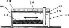
首先,讲述本发明的超声波测距装置使用的超声波振动器。图2A及图2B示出超声波振动器101的俯视图及侧视图。超声波振动器101具有振动板45、压电振动器20、促动器18和外壳46。压电振动器20安装在振动板45上,外壳46在支持部46a中支持振动板45的一端。在振动板45的另一端附近,设置着托板19。促动器18的两端,分别被外壳46及托板19固定。在振动板45的表面,还可以设置音响匹配层48。First, the ultrasonic vibrator used in the ultrasonic distance measuring device of the present invention will be described. 2A and 2B show a plan view and a side view of the
压电振动器20由PZT(钛酸锆酸铅)等压电陶瓷构成,外加电压后,在超声波区域的频率(大约20KHz以上的频率)中振动。可以将早已被超声波测距装置及超声波传感器等使用的各种超声波振动器作为压电振动器20使用。The
促动器18,例如由层叠压电陶瓷构成,作为控制电压外加直流电压后,就按照外加的电压的极性及电压的大小,如箭头所示伸长或收缩。只要维持外加的电压,促动器18就维持同样的长度。这样,被促动器18固定的托板19就使振动板45伸缩。The
安装在振动板45上的压电振动器20,外加驱动电压后,就以由压电振动器20材料和压电振动器20及振动板45的形状决定的振动模式及共振频率振动。在本实施方式中,以在振动板45的两端附近产生波节之类的弯曲(挠曲)模式振动。给促动器18外加直流电压后,振动板45伸缩,该共振频率变化。按照促动器18的位移量,共振频率连续变化。The
在本发明的超声波测距装置中,在发送用超声波振动器及接收用超声波振动器中使用该超声波振动器101,在发送频率被调制的超声波之际,一边给促动器18外加电压,一边驱动压电振动器20,从而使共振频率伴随着调制频率的变化而变化。这样,能够扩大超声波振动器的带域,能够使用频率被调制的驱动信号正确地测量距离。另外,使给促动器18外加电压的时序变化后,接收频率被调制的超声波,从而计测接收信号的信号强度的变化。In the ultrasonic distance measuring device of the present invention, the
在超声波振动器101中,使压电振动器20与振动板45粘接后振动空气。但也可以取代振动板45及压电振动器20,使用将两块压电体粘接的双压电晶片型的压电振动器。另外,在本发明的超声波测距装置中,除了超声波振动器101之外,还可以使用能够使共振频率或共鸣频率变化后收发超声波的各种结构的超声波振动器。In the
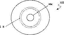
图3A及图3B所示的超声波振动器102,具有压电振动器20、振动板45、音响匹配层48、促动器18和外壳46。压电振动器20、振动板45、音响匹配层48,以振动板45被压电振动器20及音响匹配层48夹住的形式层叠。促动器18具有圆筒形状,圆筒的一端被安装在音响匹配层48上。另外,圆筒的另一端从内侧安装在外壳46的上面46b上,在上面46b上设置着孔46c。由促动器18、音响匹配层48及上面46b形成的空间,构成共鸣器46b。The
给压电振动器20外加驱动电压后,就以扩散振动模式或厚度振动模式振动。这样,音响匹配层48就以取决于共鸣器46d的尺寸共鸣频率振动,产生超声波。When a driving voltage is applied to the
给促动器18外加直流电压后,促动器18就按照箭头所示的方向伸缩。因此,共鸣器46d的尺寸变化,共鸣频率也变化。After the DC voltage is applied to the
图4是表示对促动器18的尺寸变化而言的共鸣频率的变化。如图4所示,促动器45的长度,由0.4mm成为0.1mm时,共鸣频率大约变化15KHz。FIG. 4 shows changes in resonance frequency with respect to dimensional changes of the
另外,图5所示的超声波振动器103,具有外壳46、压电振动器20、促动器18、第1音响匹配层48和第2音响匹配层47。第1音响匹配层48嵌入外壳46的一个侧面,压电振动器20与第1音响匹配层48相对地保持在外壳46内。第2音响匹配层47由液体构成,至少充满第1音响匹配层48和压电振动器20之间,被它们夹住。作为第2音响匹配层47可以使用的液体,最好是非活性溶液,使用FURORINA-TO(フロリナ一ト:3M公司的商标)等最理想。也可以使用不会给压电振动器20、促动器18及旨在给它们外加电压的布线带来腐蚀等坏影响的水及酒精等。In addition, the ultrasonic vibrator 103 shown in FIG. 5 has a housing 46 , a
促动器18,外加直流电压后伸缩,使第1音响匹配层48和压电振动器20之间的间隔变化。这样,可以使第2音响匹配层47的厚度变化,使超声波振动器103的共鸣频率变化。The
图6是表示超声波振动器103的共鸣频率变化的一个示例的曲线图。图6所示的超声波振动器103,由压电振动器20、第1音响匹配层48及第2音响匹配层47构成。压电振动器20由PZT构成,第1音响匹配层48由用环氧树脂固定了球形瓶的材料构成,第2音响匹配层47由FURORINA-TO构成。使第2音响匹配层47的厚度由0.4mm变成0.1mm时,如图6所示,共振频率由470KHz变成500KHz,约变化30KHz。接着,讲述本实施方式的超声波测距装置。如图7所示,超声波测距装置150,包括发送用超声波振动器1、接收用超声波振动器2、驱动部151、发送用控制电压生成部152、接收用控制电压生成部153、接收部154和传播时间预备计测部155。另外,还包括生成旨在规定由发送用超声波振动器1发送超声波的时序的触发信号的时序部9。FIG. 6 is a graph showing an example of changes in the resonance frequency of the ultrasonic vibrator 103 . The ultrasonic vibrator 103 shown in FIG. 6 is composed of the
在发送用超声波振动器1及接收用超声波振动器2中,使用能够使共振频率或共鸣频率变化的超声波振动器。例如,可以适当使用上述的超声波振动器101、102、103。在本实施方式中,使用超声波振动器101。The
驱动部151,驱动发送用超声波振动器1,为了发送超声波而生成频率被调制的驱动信号,将生成的驱动信号外加给发送用超声波振动器1。驱动部151最好包含载波信号生成部8、调制信号发生部44、频率调制部7和发送放大器3。图8示出驱动部151中生成的信号。载波信号生成部8,产生使发送用超声波振动器1振动的驱动信号;调制信号发生部44,生成进行频率调制的调制频率。例如,如图8所示,载波信号生成部8生成频率15KHz的矩形波的载波信号8(a),调制信号发生部44如信号(b)所示地生成在周期100微秒之间频率从15KHz向30KHz变化的调制信号8(b)。The driving
频率调制部7,用调制信号调制载波信号,将被频率调制的载波信号向发送放大器3输出。发送放大器3将接收的信号放大,将图8所示的驱动信号8(c)向发送用超声波振动器1输出。载波信号生成部8及调制信号发生部44,根据时序部9输出的触发信号,生成载波信号及调制信号,从而使2个信号的时序一致。The
发送用控制电压生成部152,生成旨在使发送用超声波振动器1的共振频率或共鸣频率变化的控制电压。因此,发送用控制电压生成部152包含DC控制电压生成部6及压电放大器5。DC控制电压生成部6从时序部9接收触发信号,生成旨在驱动促动器18的DC控制电压。压电放大器5将DC控制电压放大,将放大的控制电压外加给发送用超声波振动器1的促动器18。The transmission
外加给促动器18的DC控制电压被预先规定,从而成为使发送用超声波振动器1的共振频率或共鸣频率与驱动信号的频率的调制大致一致地变化的分布。例如,如图8(d)所示,与输出驱动信号8(d)的同时被外加,电压伴随调制频率的变化而增大、伴随驱动信号的停止而减少的DC控制电压被外加给促动器18。DC控制电压被外加给促动器18后,发送用超声波振动器1的共振频率伴随调制频率的变化而变化。发送用超声波振动器1一边使共振频率变化,一边发送驱动信号生成的超声波。The DC control voltage to be applied to the
由发送用超声波振动器1发送的超声波,向测量目标17前进,在测量目标中反射。超声波的反射波,到达接收用超声波振动器2,在接收用超声波振动器2的作用下,变换成电信号,这时,接收用超声波振动器2一边使共振频率变化,一边接收反射波。Ultrasonic waves transmitted by the transmitting
接收用控制电压生成部153,具有压电放大器5、DC控制电压生成部6和延迟部16,生成旨在使接收用超声波振动器2的共振频率或共鸣频率变化的控制电压。压电放大器5及DC控制电压生成部6,采用与发送用控制电压生成部152相同的结构。但是,DC控制电压生成部6不是根据时序部9的触发信号生成DC控制信号,而是根据来自延迟部16的输出信号生成DC控制信号。The reception control
延迟部16,从时序部及后述的计时部156接收触发信号及推定传播时间信息。然后,每逢接收触发信号时,生成长度Δt不同的延迟时间,在经过延迟时间后,向DC控制电压生成部6输出信号。用超声波测距装置150接收的反射波的强度达到给定的检知电平时,就判断检知到反射波,确定反射波的到达时刻。因此,如果设反射波的推定传播时间为ΔT0,接收波的微弱的电平的部分,在ΔT0之前到达接收用超声波振动器2。因此,检出接收信号的时序,就从比ΔT0早时间α的ΔT0-α时开始。输出2n+1次(n为1以上的整数)触发信号后,反复收发,假设推定传播时间为ΔT0,那么生成的延迟时间就是ΔT0-α-nΔt、ΔT0-α-(n-1)Δt、ΔT0-α(n-2)Δt、…ΔT0-α-2Δt、ΔT0-α-Δt、ΔT0-α、ΔT0-α+Δt、…ΔT0-α+nΔt。The
在接收用控制电压生成部153中,每逢延迟部16接收触发信号时,DC控制电压生成部就以延迟时间只有Δt不同的时序生成DC控制电压,压电放大器5将生成的DC控制电压放大,外加给接收用超声波振动器2的促动器18。In the receiving control
接收部154,包括接收放大器4、切换部10、包络线检波部13和判断部14。接收放大器4将被接收用超声波振动器2变换的接收信号放大。切换部10切换信号的输出对象,以便只将反复接收的接收信号中最初的接收信号向传播时间预备计测部155输出,而将第2次以后的接收信号向包络线检波部13输出。接收部154接收了最初的接收信号时,将接收信号向传播时间预备计测部155输出。传播时间预备计测部155,包括峰值保持部11、电平检知部12和计时部156,接收信号首先被输入峰值保持部11。图9表示传播时间预备计测部155中各部的信号的峰值保持部11,保持最初的接收信号22的峰值,将峰值信号25向电平检知部12输出。电平检知部12比较给定的临界值26和峰值信号25,在峰值信号25超过临界值26时,输出检知信号27。计时部156,接收时序部9的触发信号及检知信号27,计测从接收了触发信号起到接收了检知信号27时为止的时间,将计测结果作为推定传播时间ΔT0,向接收用控制电压生成部153的延迟部16输出。The receiving
如前所述,延迟部16在以从推定传播时间ΔT0中减去时间α的时间为中心的期间,每逢从时序部9接收触发信号时,就生成长度Δt不同的延迟时间,在经过延迟时间后,向DC控制电压生成部6输出信号。这样,每逢发送用超声波振动器1发送超声波时,接收用超声波振动器2就一边以不同的时序被外加DC控制电压,一边接收反射波。As described above, the
接收部154接收了第2次以后的接收信号时,接收信号被输入包络线检波部13。图10A示出在包络线检波部13中生成的接收信号24的包络线28。另外,图10B示出接收该接收信号24时,接收用控制电压生成部153生成的DC控制电压的分布29。在这些图中,将原点作为ΔT0-α。如图10A及图10B所示,接收信号从时刻ΔT’开始上升,表示反射波在时刻ΔT’时到达。与此不同,DC控制电压从比时刻ΔT’早的ΔT1’开始生成,外加给促动器18。When the receiving
图11A示出在包络线检波部13中对其它接收信号32检波后得到的包络线30。图11B示出接收其它接收信号32时,接收用控制电压生成部153生成的DC控制电压的分布31。如图11A及图11B所示,接收信号从时刻ΔT’开始上升,表示反射波在时刻ΔT’时到达。与此不同,DC控制电压从与时刻ΔT’一致的ΔT’2开始生成,外加给促动器18。FIG. 11A shows an
第2次以后,在反复多次进行的超声波的收发中,发送用超声波振动器1发送超声波的时序,都与时序部9中的触发信号的生成一致。另外,在发送用超声波振动器1中,用与驱动信号的频率调制一致的时序,向促动器18外加DC控制电压。就是说,被多次发送的超声波,以触发信号为基准发生,还具有相同的波形。After the second time, in the transmission and reception of ultrasonic waves repeated a plurality of times, the timing at which ultrasonic waves are transmitted by the transmitting
如果假设测量目标17是在计测中不移动的物体,那么各反射波到达接收用超声波振动器2的到达时刻,也就以触发信号为基准,是恒定,波形也相等。可是,如前所述,外加给接收用超声波振动器2的促动器18的DC控制电压,对触发信号而言,是以给定的时间间隔移位后上升地外加。反射波到达接收用超声波振动器2的时序,与外加给促动器18的DC控制电压的时序最一致时,接收用超声波振动器2的共振频率,与反射波的频率调制一致地变化,所以接收的接收信号的振幅变大。就是说,在包络线检波部13中得到的包络线的积分面积变大。Assuming that the
图12是将图10的包络线28和图11的包络线30重叠显示的图形。由该图可知:包络线30的积分面积变大。经过调制后频率变高的接收信号的后半部分,其差特别显著。这意味着:接收给予包络线30的接收信号时,接收用超声波振动器2的共振频率的变化,与反射波的频率调制一致。判定部14,FIG. 12 is a graph in which the
为了进行这种判断,如图13所示,判定部14包含积分部33、A/D变换部34及最大值判定部35,每逢包络线检波接收信号时,就在积分部33中积分包络线,在A/D变换部34中将得到的积分值变换成数字值。最大值判定部35,从延迟部16取得延迟时间和反复次数的相关信息,获得反复次数的积分值后,决定这些数字积分值成为最大时的延迟时间。这样,确定传播时间,向距离计算部15输出。既可以根据积分值成为最大时的延迟时间直接确定传播时间,也可以根据得到的积分值,进行插补,推定成为最大的积分值及给与该积分值的延迟时间。不进行插补时,延迟时间的间隔,就成为计测的精度。In order to make this judgment, as shown in FIG. 13 , the judging
距离计算部15,根据得到的超声波的传播时间,使用超声波的速度,计算出到测量目标17的距离。还可以如图7所示,根据温度计37计测测量目标17的周围的环境温度,用环境温度进行补偿。空气的音速v(m),作为温度t(℃)的函数,可以用v=331.45+0.6(t)近似表达。使用该关系式,补偿超声波的传播速度后,可以求出更正确的距离。The distance calculating unit 15 calculates the distance to the
下面,参照图14及图15~图18,讲述使用超声波测距装置150测量距离的方法。Next, referring to FIG. 14 and FIGS. 15 to 18 , a method of measuring a distance using the ultrasonic
图14是表示使用超声波测距装置150测量距离的步骤的流程图。另外,图15~图18,是测量中的不同时刻的超声波测距装置150的发送放大器3输出驱动信号(a)、发送用控制电压生成部152输出的DC控制电压信号(b)、接收放大器4输出的接收信号(c)、峰值保持部11的峰值信号(d)、包络线检出部13的输出信号(e)、接收用控制电压生成部153输出的DC控制电压信号(f)及判定部14中的积分信号(g)的时序图。首先,如图15所示,在发送部151中,生成频率被调制的驱动信号(a),使用DC控制电压信号(b),一边使发送用超声波振动器1的共振频率与驱动信号的频率调制一致地变化,一边利用驱动信号驱动发送用超声波振动器1(步骤201)。FIG. 14 is a flowchart showing a procedure for measuring a distance using the ultrasonic
由发送用超声波振动器1发送的超声波,在测量目标17中反射,反射波到达接收用超声波振动器2。接收用超声波振动器2将反射波变换成电信号,接收放大器4将电信号放大后获得接收信号(c)。根据接收信号(c),传播时间预备计测部155测量推定传播时间(步骤202)。具体地说,保持接收信号(c)的峰值,从而生成峰值信号(d)。接着,将峰值信号(d)与临界值26比较,峰值信号25超过临界值26时,检出检知信号27。将检出了检知信号27的时间,作为推定传播时间ΔT0。以从推定传播时间ΔT0减去时间α的时间为中心,在给定的期间中,能够收发、计测超声波地决定收发的反复次数及延迟时间的变化量(步骤203)。The ultrasonic wave transmitted by the
接着,在时序部9中,生成步骤203决定的反复次数的触发信号。每逢生成各触发信号时,就由发送用超声波振动器1发送超声波,还从给定的延迟时间后起,在外加了接收用的DC控制电压的接收用超声波振动器2中接收反射波。包络线检波接收部154得到的接收信号,求出包络线的积分值(步骤204、205)。Next, in the
图16、17及18示出一边使延迟时间变化,一边反复测量时的时序图。包络线检出部13的输出信号(e),按照外加DC控制电压信号(f)的时序变化,其结果,判定部14中的积分信号(g)也变化。16, 17 and 18 show timing charts when the measurement is repeated while changing the delay time. The output signal (e) of the
获得反复次数、积分值(积分信号(g))(步骤206、207)后,判定部14决定最大值及与最大值对应的延迟时间(步骤208)。距离计算部15根据需要,对超声波的传播速度进行温度补偿,根据延迟时间求出超声波的传播时间,计算出到测量目标的距离。After obtaining the number of repetitions and the integrated value (integrated signal (g)) (
采用本发明后,一边使超声波振动器的共振频率变化,一边外加频率被调制的驱动信号,或者接收频率被调制的超声波。因此,即使构成超声波振动器的压电体元件的带域狭窄,也能用宽带域收发超声波,能够发送频率被调制的超声波。这样,能够不容易受到测量环境中的杂音及风等环境的摇晃等的影响地进行高精度的测量。According to the present invention, while changing the resonance frequency of the ultrasonic vibrator, a frequency-modulated drive signal is applied, or a frequency-modulated ultrasonic wave is received. Therefore, even if the band of the piezoelectric body element constituting the ultrasonic vibrator is narrow, ultrasonic waves can be transmitted and received in a wide band, and frequency-modulated ultrasonic waves can be transmitted. In this way, it is possible to perform high-precision measurement without being easily affected by environmental fluctuations such as noise in the measurement environment and wind.
另外,本发明使用的超声波振动器,由于使用带域狭窄的压电体元件,所以可以用较小的电力驱动,能够实现将电池等作为电源、小型、便于携带的超声波测距装置。In addition, since the ultrasonic vibrator used in the present invention uses a narrow-band piezoelectric element, it can be driven with relatively small power, and a small, portable ultrasonic distance measuring device can be realized that uses a battery or the like as a power source.
另外,由于在检出接收波时不使用相关电路,所以能够使接收电路的结构简单,能够实现廉价的超声波测距装置。In addition, since a related circuit is not used when detecting a received wave, the structure of the receiving circuit can be simplified, and an inexpensive ultrasonic distance measuring device can be realized.
此外,在本实施方式中,超声波测距装置具备传播时间预备计测部。但在大体明白到要测量的测量目标的距离时,以及限制计测范围时,也可以省略传播时间预备计测部。这时,可以根据设定的范围或大体明白的距离,预先设定延迟部16发生的延迟时间,不求出推定距离地按照图14所示的步骤204以下的步骤计测。In addition, in the present embodiment, the ultrasonic distance measuring device includes a propagation time preliminary measurement unit. However, when the distance to the measurement target to be measured is generally known, or when the measurement range is limited, the propagation time preparation measurement unit may be omitted. In this case, the delay time generated by the
另外,在本实施方式中,使用发送用超声波振动器1及接收用超声波振动器2。但也可以用1个超声波振动器进行超声波的收发。这时,可以在收发用超声波振动器与发送部151及发送用控制电压生成部152和收发用超声波振动器与接收部154及接收用控制电压生成部153之间设置切换部,与收发的时序一致地切换与这些功能块的连接。In addition, in this embodiment, the
另外,在本实施方式中,驱动部生成按照调制信号调制了具有给定频率的载流信号的频率瞬变波。可是,也可以使用象频率瞬变波那样脉冲宽度及脉冲间隔变化的脉冲波。In addition, in the present embodiment, the drive unit generates a frequency transient wave in which a current carrier signal having a predetermined frequency is modulated according to a modulation signal. However, it is also possible to use a pulse wave whose pulse width and pulse interval change like a frequency transient wave.
另外,本发明使用的超声波振动器,由于使用带域狭窄的压电体元件,所以可以用较小的电力驱动,能够实现将电池等作为电源、小型、便于携带的超声波测距装置。In addition, since the ultrasonic vibrator used in the present invention uses a narrow-band piezoelectric element, it can be driven with relatively small power, and a small, portable ultrasonic distance measuring device can be realized that uses a battery or the like as a power source.
另外,由于在检出接收波时不使用相关电路,所以能够使接收电路的结构简单,能够实现廉价的超声波测距装置。In addition, since a related circuit is not used when detecting a received wave, the structure of the receiving circuit can be simplified, and an inexpensive ultrasonic distance measuring device can be realized.
另外,采用本发明后,由于使用传播时间预备计测部,首先求出大致的传播时间,所以能够扩大可以计测的范围,还能用短时间测量计测范围中的距离。In addition, according to the present invention, since the approximate propagation time is obtained first by using the propagation time preliminary measurement unit, the measurable range can be expanded, and the distance in the measurement range can be measured in a short time.
另外,使用多个本发明的超声波测距装置后,可以求出测量目标的方位。如图19所示,隔开给定的间隔L0配置超声波测距装置150及超声波测距装置150’,使用各超声波测距装置测量到测量目标17的距离。假设由超声波测距装置150及超声波测距装置150’到测量目标之间的距离为L1及L2,那么测量目标就位于以相距L0的2个点为圆心、以L1及L2为半径的2个圆的交点上。这样,就求出从超声波测距装置150及超声波测距装置150’的角度看的测量目标17的方向。使用3个以上的超声波测距装置,按照同样的步骤测量,还能求出三维空间中的测量目标的方向。In addition, by using a plurality of ultrasonic distance measuring devices of the present invention, the orientation of the measurement target can be obtained. As shown in FIG. 19 , the ultrasonic
(第2实施方式)(second embodiment)
下面,讲述采用本发明的超声波测距装置的第2实施方式。如图20所示,超声波测距装置160,包括:发送用超声波振动器1、接收用超声波振动器2、驱动部161、发送用控制电压生成部162、接收用控制电压生成部163和接收部4。另外,还具有旨在调整上述各部的控制时序的时序部169。时序部169,包括:生成成为整体的基准的时钟脉冲信号的基准时钟脉冲生成部64,向驱动部161、发送用控制电压生成部162及接收用控制电压生成部163发送触发信号的触发信号生成部63和计时部65。Next, a second embodiment of the ultrasonic distance measuring device according to the present invention will be described. As shown in FIG. 20 , the ultrasonic
如第1实施方式中所述,在发送用超声波振动器1及接收用超声波振动器2中,使用能使共振频率或共鸣频率变化的超声波振动器。具体地说,可以适当采用第1实施方式中讲述的超声波振动器101、102、103。在本实施方式中采用超声波振动器101。As described in the first embodiment, the
驱动部161,为了驱动发送用超声波振动器1发送测量用超声波而生成测量用驱动信号,将生成的测量用驱动信号外加给发送用超声波振动器1。驱动部161最好包含记忆预先生成的测量用驱动信号的波形的波形存储器61、D-A变换器62和发送放大器3。波形存储器61将预先生成的测量用驱动信号,作为数字信号记忆。D-A变换器62将数字的测量用驱动信号变换成模拟信号,向发送用超声波振动器1输出。发送放大器3将接收的信号放大,向发送用超声波振动器1输出。由波形存储器61将数字的测量用驱动信号向D-A变换器62发送的时序,取决于触发信号生成部63由向波形存储器61输出的触发信号。触发信号生成部63根据在基准时钟脉冲生成部64中生成的基准时钟脉冲,进行动作。The
如图21所示,测量用驱动信号21(a)包含驱动信号w1(第2驱动信号)及多个驱动信号w2(第1驱动信号)。驱动信号w1,检出测量用驱动信号产生的超声波的反射波到达接收用超声波振动器2的情况,使用驱动信号w2,产生进行测量之际的基准时刻。驱动信号w1,是频率在中途切换的正弦波。更具体地说,驱动信号w1,在时间ΔThh之间保持频率f2(第1频率)后,频率由f2切换成f4,在时间ΔTh2之间保持频率f4(第2频率)。多个驱动信号w2,在时间ΔTh3之间输出。在这期间,驱动信号w2的频率,从f1到f4线性变化。驱动信号w2的反复周期ΔTw,反复2N+1次。输出最初的驱动信号w2的时序,从开始输出驱动信号w1时起,是(ΔThh+ΔTww)后。从频率f1到频率f4,满足fk<f2<f3<f4。例如,各频率是:f1=20KHz、f2=40KHz、f3=60KHz、f4=80KHz。如果设ΔTh3为80μs,那么频率由20KHz起到80KHz为止线性扫描的波形,就如图22所示。As shown in FIG. 21 , the measurement drive signal 21 ( a ) includes a drive signal w1 (second drive signal) and a plurality of drive signals w2 (first drive signal). The drive signal w1 detects that the reflected wave of the ultrasonic wave generated by the measurement drive signal reaches the reception
发送用控制电压生成部162,生成使发送用超声波振动器1的共振频率或共鸣频率变化的DC控制电压。因此,发送用控制电压生成部162包含DC控制电压生成部6、DC控制电压波形存储器66及压电放大器5。在DC控制电压波形存储器66中,记忆具有使发送用超声波振动器1的共振频率或共鸣频率与测量用驱动信号的频率大体一致地变化的分布的控制电压波形。DC控制电压生成部6从DC控制电压波形存储器66读出数字的DC控制电压波形,进行D-A变换,还变换成最适合压电放大器5的范围。压电放大器5将DC控制电压放大,将放大后的控制电压外加给发送用超声波振动器1的促动器18。DC控制电压外加给促动器18后,发送用超声波振动器1一边使共振频率变化,一边发送驱动信号产生的超声波。The transmission
如图21的信号21(b)所示,在输出驱动信号w1的期间,DC控制电压在时间ΔThh之间保持驱动促动器18从而使发送用超声波振动器1的共振频率或共鸣频率成为频率f2的值;然后,在时间ΔTh2之间保持驱动促动器18从而使共振频率或共鸣频率成为频率f4的值;再然后,成为与驱动信号w2的频率变化的时序一致地驱动促动器18,从而使发送用超声波振动器1的共振频率或共鸣频率由f1向f4变化的值。As shown in the signal 21(b) of FIG. 21, during the output of the driving signal w1, the DC control voltage keeps driving the
驱动部161和发送用控制电压生成部162的动作,受触发信号生成部63的控制。具体地说,在触发信号生成部63生成的触发信号的作用下,数字的测量用驱动信号由触发信号生成部63发送给D-A变换器62,经发送放大器3放大后,驱动发送用超声波振动器1。这时,根据触发信号,从DC控制电压波形存储器66读出DC控制电压波形的数据,在压电放大器5的作用下,将DC控制电压外加给促动器18,从而使发送波形的频率与发送用超声波振动器1的共振频率一致。另外,触发信号生成部63还使计时部65开始计数,以便从开始发送信号起在时间ΔThh后计测时间。The operations of the
由发送用超声波振动器1发送的超声波,向测量目标17前进,在测量目标中反射。然后,超声波的反射波,到达接收用超声波振动器2,在接收用超声波振动器2的作用下,变换成电信号。Ultrasonic waves transmitted by the transmitting
发送用控制电压生成部163,包括压电放大器5、DC控制电压生成部6、延迟部67、存储器存储单元切换部69及DC控制电压波形存储器存储单元68,生成旨在使接收用超声波振动器2的共振频率或共鸣频率变化的DC控制电压。压电放大器5及DC控制电压生成部6采用与发送用控制电压生成部162相同的结构。但是,DC控制电压生成部6不是根据触发信号生成部63的触发信号生成DC控制电压,而是根据来自延迟部67的输出信号生成DC控制电压。DC控制电压波形存储器存储单元68,记忆第1~第3DC控制电压波形。由存储器存储单元切换部69将它切换。DC控制电压的3种波形,如图21A~图23C所示。The control
如图21A所示,第1波形具有驱动促动器18从而使发送用超声波振动器1的共振频率每隔时间ΔTh都成为f1、f2、f3的振幅,并且被DC控制电压波形存储器存储单元68的存储单元1记忆。第1波形用于判断来自测量目标的反射波是否到达接收用超声波振动器2。如图21B所示,第2波形具有驱动促动器18从而使接收用超声波振动器2的共振频率成为f2的振幅。该波形被DC控制电压波形存储器存储单元68的存储单元2记忆。第2波形(第2控制电压)用于检出根据驱动信号w1产生的超声波的反射波中的频率切换的时序。如图21C所示,第3波形使接收用超声波振动器2的共振频率在时间ΔTh3中由f1到f4线性扫描。该波形被DC控制电压波形存储器存储单元68的存储单元3记忆。第3波形(第1控制电压)用于为了求出正确的超声波的传播时间而进行的测量。As shown in FIG. 21A , the first waveform has the amplitudes of f1, f2, and f3 at every time ΔTh by driving the
接收部164包括:接收放大器4、包络线检波部13、比较器36、峰值保持部11、第1A-D变换器34、第2A-D变换器35、电压值比较部70、基准电压生成部71、时序生成部72、复位信号生成部73、接收波到达判断处理部74、数据存储器75和重心计算部76。The receiving
如前所述,在测量用驱动信号中,包含驱动信号w1及多个驱动信号w2。在接收部164中,接收根据驱动信号w1的超声波的反射波时,使用包络线检波部13、第1A-D变换器34、电压值比较部70及接收波到达判断处理部74,检出来自测量目标17的反射波到达的情况。另外,使用比较器36,生成为了求出驱动信号w2产生的超声波的正确的传播时间而进行测量之际的基准时刻。另一方面,接收了驱动信号w2产生的超声波的多个反射波时,使用峰值保持部11、第2A-D变换器35、数据存储器75及重心计算部76,求出超声波的正确的传播时间。As described above, the drive signal for measurement includes the drive signal w1 and the plurality of drive signals w2. In the
接收放大器4将接收用超声波振动器2变换的接收信号放大。包络线检波部13生成、输出接收信号的包络线信号。峰值保持部11保持接收信号的最大振幅,直到输入复位信号为止。图24A示出对接收信号81而言的峰值保持部11的输出信号82。另外,图24B示出对接收信号81而言的包络线检波部13的输出信号83。The
比较器36从包络线检波部13中接收包络线信号,在对基准电压而言,包络线信号较大时,输出High;其它时,输出Low。基准电压根据计时部65的计数值,由基准电压生成部71生成。基准电压与计时部65的计数值成反比地生成。The
第2A-D变换器35将峰值保持部11的电压值,变换成数字值。此外,峰值保持部11的复位信号及第2A-D变换器35的时钟脉冲信号,根据基准时钟脉冲生成部64生成的基准时钟脉冲,由时序生成部72生成。第1A-D变换器34将包络线检波部13的输出信号,变换成数字值。另外,电压值比较部70为了检出第1A-D变换器34的输出信号的变动,以给定的时序,将第1A-D变换器34的输出信号的值与其前后的值进行比较。第1A-D变换器34的取样时钟脉冲,由时序生成部72生成。另外,电压值比较部70中的比较的时序,也与时序生成部72输出的时钟脉冲信号同步。The second
接收波到达判断处理部74,根据电压值比较部70的输出,判断反射波是否到达。数据存储器75,记忆第2A-D变换器35的输出。重心计算部76也使用数据存储器75记忆的数据,求出接收信号强度——第2A-D变换器35的输出值的延迟时间轴上的重心。The received wave arrival
接着,参照图20及图21,讲述超声波测距装置160的动作及计测距离的方法。如前所述,发送部161生成测量用驱动信号21(a),由发送用超声波振动器1发送测量用超声波。这时,使用发送用控制电压生成部162生成的信号21(b)、驱动发送用超声波振动器1的促动器18,使发送用超声波振动器1的共振频率变化。Next, the operation of the ultrasonic
如图21的信号21(c)所示,超声波测距装置160处于待机状态时,或开始计测时,接收用控制电压生成部163的输出为零。这时,不给接收用超声波振动器2的促动器18外加电压,接收用超声波振动器2的共振频率是f1。然后,输出存储单元1的波形,在各时间ΔTh中都使接收用超声波振动器2的共振频率成为f1、f2、f3地变化。进而,在每个取样时间ΔTh中,用第1A-D变换器34计测检波电路的输出电压。计测的时序,为取得接收用超声波振动器2的共振频率即将变化之前的值。输出存储单元2的波形的时序,取决于超声波测距装置160测量的距离。超声波测距装置160进行近距离的测量时,可以与发送超声波的同时,或刚发送超声波之后,输出存储单元1的波形。另外,由发送用超声波振动器1发送的超声波有可能直接到达接收用超声波振动器2时,最好在发送完超声波之后输出存储单元1的波形。As shown in a signal 21(c) of FIG. 21 , when the ultrasonic
考虑到包络线检波部13的时间常数及促动器18的应答时间,取样时间ΔTh最好是测量使用的超声波的5个波长以上。例如:f2是40KHz时,ΔTh最好是25μs×5=125μs。这时,第1A-D变换器34的取样周期是8KHz。另外,在驱动信号w1中,维持频率f2的时间ΔThh,最好是ΔTh的4倍以上。另外,由于驱动信号w1是为了产生求出驱动信号w2产生的超声波的正确的传播时间而进行测量之际的基准,所以在f2为40KHz时,时间ΔThh最好是2ms左右。Considering the time constant of the
接收用超声波振动器2接收反射波后,用接收放大器4生成接收信号,用包络线检波部13生成包络线检波信号。包络线检波信号被第1A-D变换器34变换成数字值。在各取样周期中,电压值比较部70比较接收用超声波振动器2的共振频率成为f2时的值和其前后的值,与前后的值之比为某个基准值以上时,判断来自障碍物17的反射波到达了。因为接收用超声波振动器2的共振频率与反射波的频率一致时,用很大的强度接收反射波。该基准值根据基准电压生成部71的值决定。另外,判断由接收波到达判断处理部74进行。基准电压值越小,到测量目标的距离越大,就意味着反射波越要衰减,接收信号也要随之衰减。因此,基准值也就设定得较小。After the
不是来自测量目标17的反射波,而是白色噪声等时,第1A-D变换器34的电压值,与接收用超声波振动器2的共振频率无关,成为恒定。是红色噪声时,接收用超声波振动器2的共振频率越低,第1A-D变换器34的电压值就越大。所以,将噪声误认为测量用的超声波可能性极小。When there is white noise or the like instead of the reflected wave from the
接收波到达判断处理部74判断反射波到达后,检出大致的传播时间。检出的时间成为旨在求出正确的传播时间的基准时间。接收波到达判断处理部74判断反射波到达时,向存储器存储单元切换部69输出信号,存储器存储单元切换部69将DC控制电压波形存储器存储单元68的存储单元设定为存储单元2。这样,存储单元2的波形的DC控制电压外加给接收用超声波振动器2的促动器18。接收用超声波振动器2的共振频率维持成为f2。接收信号的频率由f2切换成f4后,由于频率不一致,所以接收信号的强度急剧下降,包络线检波部13的输出下降。比较器36比较包络线检波部13的输出和基准电压,包络线检波部13的输出比基准电压小时,将输出由High切换成Low。计时部65记忆比较器36的输出变化的时刻T1。The reception wave arrival
比较器36的基准电压,采用比检出反射波之际、第1A-D变换器34判断接收波到达时的包络线检波部13的输出值小的值(例如-3dB)。根据实际检出的反射波的接收强度,确定比较器36的基准电压,从而即使接受信号因传输距离及环境而衰减,也能正确地计测。The reference voltage of the
在计时部65内记忆时刻T1后,解除峰值保持部11的复位。复位信号由复位信号生成部73生成。另外,同时还由复位信号生成部73向存储器存储单元切换部69输出信号,将DC控制电压波形存储器存储单元68的存储单元设定成存储单元3。After the time T1 is memorized in the
如图21的信号21(a)所示,驱动信号w2在周期ΔTw中反复输出。这样,从时刻T1开始,在周期ΔTw中反射波到达接收用超声波振动器2,检出接收信号。与此不同,驱动接收用超声波振动器2的促动器18的DC控制电压,对多个驱动信号w2产生的超声波的反射波到达的时序而言,分别在长度Δt不同的延迟时间后输出。该延迟时间和第1实施方式一样,以反射波到达的时序为中心,在时间轴上,从快的方向向慢的方向给予。假如驱动信号w2的数量是2N+1,那么延迟时间就是-N×Δt、-(N-1)×Δt、-(N-2)×Δt…Δt、1×Δt、2×Δt…N×Δt。As shown by a signal 21(a) in FIG. 21, the drive signal w2 is repeatedly output in a period ΔTw. In this way, from the time T1, the reflected wave reaches the receiving
反射波的到达时间,以时刻T1为基准,是ΔTww、ΔTww+ΔTw、ΔTww+2×ΔTw、ΔTww+3×ΔTw…ΔTww+2×ΔTw。这样,驱动接收用超声波振动器2的促动器18的DC控制电压外加的时序,就以时刻T1为基准,在m=1、2、…2N+1时,成为ΔTww-(N-m)×Δt+ΔTw×(m-1)。The arrival time of the reflected wave is ΔTww, ΔTww+ΔTw, ΔTww+2×ΔTw, ΔTww+3×ΔTw...ΔTww+2×ΔTw based on time T1. In this way, the timing of applying the DC control voltage to drive the
如图21的信号21(e)所示,检出最初的驱动信号w2产生的超声波的反射时,从时刻T1开始,在时间(ΔTww-(N)×Δt)后,由压电放大器5外加给接收用超声波振动器2的促动器18DC控制电压。然后,从时刻T1开始,在时间(ΔTww-(N)×Δt+ΔTw-α)后,由第2A-D变换器35读取峰值保持部11的输出信号,存入数据存储器75中。As shown in the signal 21(e) of FIG. 21, when detecting the reflection of the ultrasonic wave generated by the initial drive signal w2, the
检出下一个驱动信号w2产生的超声波的反射时,从时刻T1开始,在时间(ΔTww-(N-1)×Δt+ΔTw)后,由压电放大器5外加给接收用超声波振动器2的促动器18DC控制电压。然后,从时刻T1开始,在时间(ΔTww-(N-2)×Δt+2×ΔTw-α)后,由第2A-D变换器35读取峰值保持部11的输出信号,存入数据存储器75中。来自第2A-D变换器35的读取完毕后,就将峰值保持部11复位。When the reflection of the ultrasonic wave generated by the next driving signal w2 is detected, the
这样,so,
1、将从时刻T1开始,在时间(ΔTww-(N-(m-1))×Δt+ΔTw×(m-1))后,给接收用超声波振动器2的促动器18DC外加控制电压。1. Starting from time T1, after the time (ΔTww-(N-(m-1))×Δt+ΔTw×(m-1)), a control voltage is applied to the actuator 18DC of the receiving
2、从时刻T1开始,在时间(ΔTww-(N-m)×Δt+ΔTw×m-α)后,由第2A-D变换器35读取峰值保持部11的输出信号,存入数据存储器75中。2. From time T1, after the time (ΔTww-(N-m)×Δt+ΔTw×m-α), the output signal of the
3、来自第2A-D变换器35的读取完毕后,就将峰值保持部11复位这一系列动作反复进行到m达到2N+1为止。3. After the reading from the second
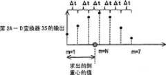
反复计测结束后,重心计算部76读取数据存储器75记忆的2N+1个数据,将这些数据排列成Δt间隔,求出第2A-D变换器35的输出值的延迟时间轴上的重心ΔtG。如果设接收各驱动信号w2产生的超声波的反射波后获得的第2A-D变换器35的输出值为Am,那么重心ΔtG可以由下列公式求出。After the repeated measurement, the center of
[公式1][Formula 1]
N=3时,如用图表示,就可以获得图25所示的曲线图。When N=3, the graph shown in FIG. 25 can be obtained as shown in the graph.
接收的反射波的频率变化的时序和接收用超声波振动器2的共振频率的变化的时序越接近,第2A-D变换器35的输出值就越大,时序离得越远,就越小。这样,求出第2A-D变换器35的输出值的延迟时间轴上的重心ΔtG后,即使接收的反射波的频率变化的时序和接收用超声波振动器2的共振频率的变化的时序不完全一致,也能插补延迟时间。就是说,在求出的延迟时间轴上的重心ΔtG中,表示接受信号强度的第2A-D变换器35的输出值成为最大,重心ΔtG成为接收的反射波的频率变化的时序和接收用超声波振动器2的共振频率的变化的时序最一致的延迟时间。The closer the timing of the frequency change of the received reflected wave to the timing of the resonance frequency change of the receiving
N最好是3以上。N越小,Δt就越大;N越大,Δt就越小。另外,第2A-D变换器35的取样频率例如在ΔTw是100μs时,成为10KHz。另外,第2A-D变换器35的分辨能,影响重心计算的精度,所以最好是10比特以上。N is preferably 3 or more. The smaller N, the larger Δt; the larger N, the smaller Δt. In addition, the sampling frequency of the second
从求出的接受信号强度的重心ΔtG减去N×Δt后,再加上T1的时间,成为传播时间。将音速与求出的传播时间相乘后,就求出到测量目标17为止的往返距离,用2除该值后,就求出到测量目标17的距离。和第1实施方式一样,最好进行温度补偿。The propagation time is obtained by subtracting N×Δt from the center of gravity ΔtG of the obtained received signal strength, and adding the time T1. The round-trip distance to the
采用本实施方式的超声波测距装置后,和第1实施方式一样,一边使超声波振动器的共振频率变化,一边外加频率被调制的驱动信号,或接收频率被调制的超声波。因此,即使构成超声波振动器的压电体元件的带域狭窄,也能用宽带域收发超声波,也能收发频率被调制的超声波。所以,能够不容易受到测量环境中的噪声及风等环境摇晃等的影响,进行高精度的测量。特别是改进来自测量目标的反射波的检出方法后,即使接收信号因测量距离及环境而衰减,也能正确地测量。According to the ultrasonic distance measuring device of this embodiment, as in the first embodiment, while changing the resonance frequency of the ultrasonic vibrator, a frequency-modulated drive signal is applied, or a frequency-modulated ultrasonic wave is received. Therefore, even if the band of the piezoelectric element constituting the ultrasonic vibrator is narrow, ultrasonic waves can be transmitted and received in a wide band, and ultrasonic waves with modulated frequency can also be transmitted and received. Therefore, it is less likely to be affected by noise in the measurement environment, environmental fluctuations such as wind, and the like, and high-precision measurement can be performed. In particular, by improving the detection method of the reflected wave from the measurement target, even if the received signal is attenuated by the measurement distance and the environment, it can be accurately measured.
此外,在本实施方式中,按照给定的时间间隔多次发送频率调制的超声波,使接收用超声波振动器的共振频率变化的时序——旨在外加DC控制电压的延迟时间在各Δt中变化。就是说,使发送频率调制的超声波的时间间隔恒定,使向接收用超声波振动器外加DC控制电压的延迟时间变化。可是,这些时间间隔及延迟时间,只要一方恒定另一方变化,就能求出超声波的正确的传播时间。这样,如图26所示,将频率调制的驱动信号的时间间隔各错开Δt,使向接收用超声波振动器外加DC控制电压的延迟时间恒定,也能如上所述求出超声波的正确的传播时间。In addition, in this embodiment, frequency-modulated ultrasonic waves are transmitted multiple times at predetermined time intervals, and the timing of changing the resonance frequency of the receiving ultrasonic vibrator—the delay time for applying the DC control voltage—changes for each Δt. . That is, the time interval for transmitting frequency-modulated ultrasonic waves is kept constant, and the delay time for applying a DC control voltage to the receiving ultrasonic vibrator is varied. However, if one of these time intervals and delay times is constant and the other is variable, the correct propagation time of ultrasonic waves can be obtained. In this way, as shown in FIG. 26, the time intervals of the frequency-modulated driving signals are shifted by Δt, and the delay time of applying the DC control voltage to the receiving ultrasonic vibrator is constant, and the correct propagation time of the ultrasonic wave can also be obtained as described above. .
在本实施方式的超声波测距装置中,驱动部生成按照调制信号对具有给定频率的载波信号加以调制的频率瞬变波。可是,和第1实施方式一样,还可以使用象频率瞬变波那样脉冲宽度及脉冲间隔变化的脉冲波。另外,如第1实施方式所述,也可以使用多个本实施方式的超声波测距装置,实现能够求出测量目标的方位的方位计。In the ultrasonic distance measuring device according to the present embodiment, the drive unit generates a frequency transient wave in which a carrier signal having a predetermined frequency is modulated according to the modulation signal. However, as in the first embodiment, a pulse wave whose pulse width and pulse interval changes like a frequency transient wave can also be used. In addition, as described in the first embodiment, a plurality of ultrasonic distance measuring devices according to this embodiment may be used to realize an azimuth gauge capable of obtaining the azimuth of a measurement target.
本发明作为求出到测量目标的距离的距离计,可以在各种领域中使用,因为使用超声波,所以可以在计算到用激光难以求出距离的粉体、镜面体、透明体等测量目标的距离中使用。另外,因为具有前文讲述的特长,所以在噪声很大的环境以及由于风等大气摇晃等时,在现有技术的超声波测距装置不适合的环境中,使用本发明的超声波测距装置后,也能够正确测量距离。这种特征,作为机器人的环境读出装置,也宜于使用本发明的超声波测距装置。The present invention can be used in various fields as a distance meter to obtain the distance to the measurement target. Since ultrasonic waves are used, it can be used to calculate distances to measurement targets such as powders, specular objects, and transparent objects that are difficult to obtain with laser light. used in distance. In addition, because of the advantages described above, the ultrasonic distance measuring device of the present invention is used in an environment where the ultrasonic distance measuring device of the prior art is not suitable in a noisy environment or due to atmospheric shaking such as wind, etc. It is also possible to measure distances correctly. This feature is also suitable for using the ultrasonic distance measuring device of the present invention as an environment reading device for a robot.
另外,由于不容易受到环境的影响,所以可以在超声波流量计中适当使用本发明的超声波测距装置。这时,隔着应该测量的流体移动的流路,将在发送用超声波振动器和接收用超声波振动器之间形成的超声波传播途径不与流体的移动方向正交地相对配置发送用超声波振动器和接收用超声波振动器。预先求出发送用超声波振动器和接收用超声波振动器之间的距离,及流体静止时的超声波的传播速度。由发送用超声波振动器直接向接收用超声波振动器发送超声波,按照前文讲述的步骤,求出传播时间。由于计测的传播时间,受到由超声波的传播途径和流体的移动方向决定的流体的移动带来的影响,所以可以根据计测的传播时间、传播距离及流体静止时的超声波的传播速度,求出流体的移动速度及流量。In addition, since it is not easily affected by the environment, the ultrasonic distance measuring device of the present invention can be suitably used in an ultrasonic flowmeter. In this case, the transmitting ultrasonic vibrator is arranged so that the ultrasonic propagation path formed between the transmitting ultrasonic vibrator and the receiving ultrasonic vibrator is not perpendicular to the moving direction of the fluid across the flow path through which the fluid to be measured is moved. and receiving ultrasonic vibrator. The distance between the transmitting ultrasonic vibrator and the receiving ultrasonic vibrator, and the propagation velocity of the ultrasonic waves when the fluid is at rest are obtained in advance. The ultrasonic wave is directly transmitted from the ultrasonic vibrator for transmission to the ultrasonic vibrator for reception, and the propagation time is obtained according to the procedure described above. Since the measured propagation time is affected by the movement of the fluid determined by the propagation path of the ultrasonic wave and the moving direction of the fluid, it can be calculated based on the measured propagation time, propagation distance, and the propagation speed of the ultrasonic wave when the fluid is still. The velocity and flow rate of the fluid.
本发明的超声波测距装置,不容易受到杂波及噪声、周围的媒体的摇晃等的影响,能够正确地测量到目标的距离。可在各种用途的距离测量装置中使用。另外,还可以在机器人的环境读出装置、流量计、方位计等中使用。The ultrasonic distance measuring device of the present invention is not easily affected by clutter and noise, shaking of surrounding media, etc., and can accurately measure the distance to a target. Can be used in distance measuring devices for various purposes. In addition, it can also be used in robot environment sensing devices, flow meters, azimuth meters, and the like.
另外,本发明的超声波振动器,可以在要求在宽带域中振动的各种超声波装置中适当使用,能够用小电力驱动,所以适合在携带性优异的超声波装置中采用。In addition, the ultrasonic vibrator of the present invention can be suitably used in various ultrasonic devices that require vibration in a wide band, and can be driven with a small power, so it is suitable for use in ultrasonic devices that are excellent in portability.
Claims (25)
Translated fromChineseApplications Claiming Priority (2)
| Application Number | Priority Date | Filing Date | Title |
|---|---|---|---|
| JP133303/2004 | 2004-04-28 | ||
| JP2004133303 | 2004-04-28 |
Publications (2)
| Publication Number | Publication Date |
|---|---|
| CN1820213Atrue CN1820213A (en) | 2006-08-16 |
| CN100573191C CN100573191C (en) | 2009-12-23 |
Family
ID=35241805
Family Applications (1)
| Application Number | Title | Priority Date | Filing Date |
|---|---|---|---|
| CNB2005800006562AExpired - LifetimeCN100573191C (en) | 2004-04-28 | 2005-04-26 | Supersonic range finder |
Country Status (4)
| Country | Link |
|---|---|
| US (1) | US7046015B2 (en) |
| JP (1) | JP3810430B2 (en) |
| CN (1) | CN100573191C (en) |
| WO (1) | WO2005106530A1 (en) |
Cited By (17)
| Publication number | Priority date | Publication date | Assignee | Title |
|---|---|---|---|---|
| CN102590815A (en)* | 2011-01-05 | 2012-07-18 | 苏州巴米特信息科技有限公司 | Ultrasonic wave-based mobile ranging method |
| CN103809168A (en)* | 2012-11-07 | 2014-05-21 | 现代摩比斯株式会社 | Method for processing ultrasonic wave sensor information of high speed drive in vehicle |
| CN104101870A (en)* | 2014-05-27 | 2014-10-15 | 浙江工商大学 | Frequency domain modulation type ultrasonic distance measuring system frequency inflection point judging method |
| CN104236647A (en)* | 2013-10-30 | 2014-12-24 | 安徽恩米特微电子股份有限公司 | Ultrasonic flowmeter based on single-chip microcomputer |
| CN106726380A (en)* | 2017-01-05 | 2017-05-31 | 东北大学秦皇岛分校 | Electronics blind waveguided shoe |
| CN107015230A (en)* | 2017-03-15 | 2017-08-04 | 中国人民解放军63655部队 | A kind of ultrasonic ranging method |
| CN108351403A (en)* | 2016-03-03 | 2018-07-31 | 密克罗奇普技术公司 | Ultrasonic wave proximity sensing peripheral equipment based on core independence peripheral equipment |
| CN108431553A (en)* | 2015-12-31 | 2018-08-21 | 贺里来倍株式会社 | The cone shaped area flow meter of range measurement in the way of magnetostriction |
| CN108802740A (en)* | 2018-06-11 | 2018-11-13 | 浙江国自机器人技术有限公司 | A kind of method, apparatus, equipment and the storage medium of ultrasound examination barrier |
| CN108896659A (en)* | 2017-06-11 | 2018-11-27 | 嘉兴博感科技有限公司 | A kind of method and system of enlarged configuration health monitoring range |
| CN109901173A (en)* | 2019-03-28 | 2019-06-18 | 如皋忠广电子技术有限公司 | Ultrasonic ranging method, device and electronic equipment based on duty cycle adjustment |
| CN109901172A (en)* | 2019-03-28 | 2019-06-18 | 如皋忠广电子技术有限公司 | Ultrasonic ranging method, device and the electronic equipment adjusted based on frequency |
| CN110494764A (en)* | 2017-04-10 | 2019-11-22 | 株式会社电装 | Object checking device |
| CN111609901A (en)* | 2020-05-24 | 2020-09-01 | 哈尔滨理工大学 | A high-precision short-distance ultrasonic liquid level measuring device |
| CN111788821A (en)* | 2018-03-09 | 2020-10-16 | 三星电子株式会社 | Use of Ultrasound to Test the Environment of Electronic Equipment |
| CN113196095A (en)* | 2018-12-18 | 2021-07-30 | 株式会社电装 | Object detection device |
| CN113466874A (en)* | 2020-03-30 | 2021-10-01 | 爱信精机株式会社 | Object detection system and object detection device |
Families Citing this family (46)
| Publication number | Priority date | Publication date | Assignee | Title |
|---|---|---|---|---|
| US7575371B1 (en)* | 2004-11-11 | 2009-08-18 | Fieldmetrics, Inc | Temperature sensor and extensometer |
| US7990270B2 (en) | 2005-01-28 | 2011-08-02 | Kirsen Technologies Corporation Inc. | Transportation security system and associated methods |
| US8643503B2 (en) | 2005-01-28 | 2014-02-04 | Kirill Mostov | Transportation security system and associated methods |
| JP5103794B2 (en)* | 2006-05-31 | 2012-12-19 | アイシン精機株式会社 | Obstacle detection device and position identification method |
| JP5103793B2 (en)* | 2006-05-31 | 2012-12-19 | アイシン精機株式会社 | Obstacle detection device and position identification method |
| DE102006032542A1 (en)* | 2006-07-13 | 2008-01-17 | Robert Bosch Gmbh | Method for distance measurement and ultrasonic distance sensor |
| JP5283888B2 (en)* | 2006-11-02 | 2013-09-04 | 株式会社東芝 | Ultrasonic diagnostic equipment |
| CN100592199C (en)* | 2006-11-10 | 2010-02-24 | 鸿富锦精密工业(深圳)有限公司 | Auto-focusing projector and auto-focusing method thereof |
| EP2100255A4 (en)* | 2006-12-06 | 2013-12-04 | Kirsen Technologies Corp | SYSTEM AND METHOD FOR DETECTING OBJECTS AND HAZARDOUS SUBSTANCES |
| GB0710078D0 (en)* | 2007-05-25 | 2007-07-04 | Stfc Science & Technology | Extension sensing actuator |
| US8257612B2 (en)* | 2007-07-05 | 2012-09-04 | Cabot Corporation | Compositions having multiple responses to excitation radiation and methods for making same |
| GB0717031D0 (en) | 2007-08-31 | 2007-10-10 | Raymarine Uk Ltd | Digital radar or sonar apparatus |
| EP2620785B1 (en)* | 2007-10-24 | 2017-12-06 | Kirsen Technologies Corporation | A system and method for space control and remote monitoring |
| EP2223152A4 (en) | 2007-11-20 | 2011-04-20 | Kirsen Technologies Corp | APPARATUS FOR DETECTION AND REMOTE MONITORING OF CONCEALED OBJECTS |
| DE102007060346A1 (en)* | 2007-12-14 | 2009-06-18 | Hochschule Offenburg | Delay measuring method for two dimensional or three dimensional-positioning of objects, involves evaluating correlation signal according to magnitude and phase for determining delay of ultrasonic pulse at transmission path |
| US8555721B2 (en)* | 2007-12-27 | 2013-10-15 | Scott Taillet | Sound measuring device |
| FR2928346B1 (en)* | 2008-03-05 | 2011-09-16 | Hutchinson | ANTI-FRICTION / DEFROSTING SYSTEM AND METHOD AND AIRCRAFT STRUCTURE INCORPORATING SAID SYSTEM |
| US9331656B1 (en)* | 2010-06-17 | 2016-05-03 | Steven M. Gottlieb | Audio systems and methods employing an array of transducers optimized for particular sound frequencies |
| CN102957483A (en)* | 2011-08-25 | 2013-03-06 | 深圳光启高等理工研究院 | Terminal device, system and method for realizing communication by sound wave |
| EP2793044B1 (en) | 2011-12-12 | 2016-11-02 | Murata Manufacturing Co., Ltd. | Position measurement device |
| US9945945B2 (en) | 2012-02-28 | 2018-04-17 | Nec Corporation | Signal processing apparatus, object detecting apparatus, apparatus provided with object detecting function, and object detecting method |
| KR102193234B1 (en)* | 2013-11-25 | 2020-12-18 | 현대모비스 주식회사 | Device for increasing the detection distance of ultrasonic sensors of vehicle and method thereof |
| EP2977789A1 (en)* | 2014-07-25 | 2016-01-27 | Nxp B.V. | Distance measurement |
| DE102015107752A1 (en)* | 2015-05-18 | 2016-11-24 | Endress + Hauser Flowtec Ag | Method for determining at least one tube wall resonance frequency and clamp-on ultrasonic flowmeter |
| US10107902B2 (en)* | 2015-09-29 | 2018-10-23 | Microchip Technology Incorporated | Core independent peripheral based ultrasonic ranging peripheral |
| CN106443575A (en)* | 2016-06-29 | 2017-02-22 | 西藏舟航物联科技有限公司 | Positioning method, positioner, radio frequency positioning device, and positioning system |
| CN106324606A (en)* | 2016-07-26 | 2017-01-11 | 京东方科技集团股份有限公司 | Pen, distance measurement method and terminal system |
| KR101939383B1 (en) | 2016-10-18 | 2019-04-10 | 현대오트론 주식회사 | Apparatus and method for driving ultrasonic sensor |
| WO2018175503A2 (en)* | 2017-03-20 | 2018-09-27 | Los Alamos National Security, Llc | Simultaneous real-time measurement of composition, flow, attenuation, density, and pipe-wall thickness in multiphase fluids |
| CN110160603B (en)* | 2018-02-11 | 2024-01-26 | 宁波方太厨具有限公司 | Oil cup liquid level measuring device of range hood |
| CN108267741A (en)* | 2018-03-12 | 2018-07-10 | 苏州青飞智能科技有限公司 | A kind of ultrasonic probe caliberating device and the method for demarcating ultrasonic probe |
| EP3617665B1 (en)* | 2018-08-29 | 2020-08-19 | Huba Control Ag | Ultrasonic flow meter |
| EP3629058B1 (en)* | 2018-09-27 | 2025-02-26 | Elmos Semiconductor SE | Method for carrying out a diagnosis or a self-test in an ultrasound monitoring system |
| JP7127465B2 (en)* | 2018-10-03 | 2022-08-30 | 株式会社Soken | Object detection device |
| JP7238422B2 (en)* | 2019-01-22 | 2023-03-14 | 株式会社リコー | distance measuring method, distance measuring device, in-vehicle device, moving body, distance measuring system |
| CN111220816B (en)* | 2020-01-19 | 2022-04-08 | 中船重工海声科技有限公司 | Time Difference Ultrasonic Velocity Measurement Method Using Frequency Hopping Signal |
| DE102020206622A1 (en)* | 2020-05-27 | 2021-12-02 | Robert Bosch Gesellschaft mit beschränkter Haftung | Method for determining the speed of an object with an ultrasonic pulse |
| CN111965652B (en)* | 2020-08-20 | 2024-03-12 | 国网黑龙江省电力有限公司电力科学研究院 | Live working protective cap based on random forest algorithm |
| JP7480637B2 (en)* | 2020-08-25 | 2024-05-10 | 株式会社Soken | Object detection device |
| FR3125330B1 (en)* | 2021-07-19 | 2024-01-12 | Commissariat Energie Atomique | Device for emitting and/or detecting acoustic waves with variable resonance frequency |
| CN114578363B (en)* | 2022-03-04 | 2023-10-13 | 苏州优达斯汽车科技有限公司 | Ultrasonic detection system and method |
| CN114740427A (en)* | 2022-05-26 | 2022-07-12 | 中国农业银行股份有限公司 | Indoor positioning method, device, equipment and medium |
| DE102022114985B3 (en) | 2022-06-14 | 2023-10-05 | Krohne Ag | Ultrasonic flow meter |
| CN116818047B (en)* | 2023-04-25 | 2024-01-12 | 河北华创测控技术有限公司 | Integrated intelligent ultrasonic liquid level meter |
| JP2024159196A (en)* | 2023-04-28 | 2024-11-08 | 株式会社東海理化電機製作所 | Ultrasonic sensor drive control device and ultrasonic sensor drive control method |
| KR20240162259A (en)* | 2023-05-08 | 2024-11-15 | 엘지이노텍 주식회사 | Positioning device of digital key |
Family Cites Families (7)
| Publication number | Priority date | Publication date | Assignee | Title |
|---|---|---|---|---|
| US3914987A (en)* | 1973-10-03 | 1975-10-28 | Krautkramer Branson | Ultrasonic measuring apparatus for determining wall thickness of a workpiece |
| JPS5288013A (en) | 1976-01-17 | 1977-07-22 | Canon Inc | Ultrasonic transducer |
| JPS585099A (en)* | 1981-07-01 | 1983-01-12 | Oki Electric Ind Co Ltd | Resonance variable type underwater transceiver |
| JPS61220593A (en)* | 1985-03-27 | 1986-09-30 | Hitachi Ltd | underwater transmitter |
| JPS639876A (en) | 1986-06-30 | 1988-01-16 | Tokyo Keiki Co Ltd | Method and device for measuring distance by ultrasonic wave |
| JPH07104063A (en) | 1993-10-04 | 1995-04-21 | Matsushita Electric Ind Co Ltd | Ultrasonic object measuring device |
| US6323441B1 (en)* | 2000-03-10 | 2001-11-27 | Honeywell International Inc. | Ultrasonic distance measuring system for monitoring railroad car loads |
- 2005
- 2005-04-26JPJP2006516894Apatent/JP3810430B2/ennot_activeExpired - Lifetime
- 2005-04-26CNCNB2005800006562Apatent/CN100573191C/ennot_activeExpired - Lifetime
- 2005-04-26WOPCT/JP2005/007915patent/WO2005106530A1/ennot_activeCeased
- 2005-08-29USUS11/214,426patent/US7046015B2/ennot_activeExpired - Lifetime
Cited By (23)
| Publication number | Priority date | Publication date | Assignee | Title |
|---|---|---|---|---|
| CN102590815A (en)* | 2011-01-05 | 2012-07-18 | 苏州巴米特信息科技有限公司 | Ultrasonic wave-based mobile ranging method |
| CN103809168A (en)* | 2012-11-07 | 2014-05-21 | 现代摩比斯株式会社 | Method for processing ultrasonic wave sensor information of high speed drive in vehicle |
| CN103809168B (en)* | 2012-11-07 | 2017-11-17 | 现代摩比斯株式会社 | Self-adapting ultrasonic sensor information processing method during high vehicle speeds |
| CN104236647A (en)* | 2013-10-30 | 2014-12-24 | 安徽恩米特微电子股份有限公司 | Ultrasonic flowmeter based on single-chip microcomputer |
| CN104101870A (en)* | 2014-05-27 | 2014-10-15 | 浙江工商大学 | Frequency domain modulation type ultrasonic distance measuring system frequency inflection point judging method |
| CN104101870B (en)* | 2014-05-27 | 2016-06-22 | 浙江工商大学 | A kind of frequency domain modulation formula ultrasonic ranging system frequency inflection point method of discrimination |
| CN108431553A (en)* | 2015-12-31 | 2018-08-21 | 贺里来倍株式会社 | The cone shaped area flow meter of range measurement in the way of magnetostriction |
| CN108351403B (en)* | 2016-03-03 | 2023-08-25 | 密克罗奇普技术公司 | Ultrasonic Proximity Sensing Peripheral Based on Core Standalone Peripheral |
| CN108351403A (en)* | 2016-03-03 | 2018-07-31 | 密克罗奇普技术公司 | Ultrasonic wave proximity sensing peripheral equipment based on core independence peripheral equipment |
| CN106726380A (en)* | 2017-01-05 | 2017-05-31 | 东北大学秦皇岛分校 | Electronics blind waveguided shoe |
| CN107015230B (en)* | 2017-03-15 | 2019-12-06 | 中国人民解放军63655部队 | ultrasonic ranging method |
| CN107015230A (en)* | 2017-03-15 | 2017-08-04 | 中国人民解放军63655部队 | A kind of ultrasonic ranging method |
| CN110494764A (en)* | 2017-04-10 | 2019-11-22 | 株式会社电装 | Object checking device |
| CN110494764B (en)* | 2017-04-10 | 2023-04-04 | 株式会社电装 | Object detection device |
| CN108896659A (en)* | 2017-06-11 | 2018-11-27 | 嘉兴博感科技有限公司 | A kind of method and system of enlarged configuration health monitoring range |
| CN111788821A (en)* | 2018-03-09 | 2020-10-16 | 三星电子株式会社 | Use of Ultrasound to Test the Environment of Electronic Equipment |
| CN111788821B (en)* | 2018-03-09 | 2022-07-12 | 三星电子株式会社 | Method and device for detecting surface near electronic equipment |
| CN108802740A (en)* | 2018-06-11 | 2018-11-13 | 浙江国自机器人技术有限公司 | A kind of method, apparatus, equipment and the storage medium of ultrasound examination barrier |
| CN113196095A (en)* | 2018-12-18 | 2021-07-30 | 株式会社电装 | Object detection device |
| CN109901173A (en)* | 2019-03-28 | 2019-06-18 | 如皋忠广电子技术有限公司 | Ultrasonic ranging method, device and electronic equipment based on duty cycle adjustment |
| CN109901172A (en)* | 2019-03-28 | 2019-06-18 | 如皋忠广电子技术有限公司 | Ultrasonic ranging method, device and the electronic equipment adjusted based on frequency |
| CN113466874A (en)* | 2020-03-30 | 2021-10-01 | 爱信精机株式会社 | Object detection system and object detection device |
| CN111609901A (en)* | 2020-05-24 | 2020-09-01 | 哈尔滨理工大学 | A high-precision short-distance ultrasonic liquid level measuring device |
Also Published As
| Publication number | Publication date |
|---|---|
| US20060022680A1 (en) | 2006-02-02 |
| JP3810430B2 (en) | 2006-08-16 |
| JPWO2005106530A1 (en) | 2007-12-13 |
| CN100573191C (en) | 2009-12-23 |
| WO2005106530A1 (en) | 2005-11-10 |
| US7046015B2 (en) | 2006-05-16 |
Similar Documents
| Publication | Publication Date | Title |
|---|---|---|
| CN1820213A (en) | Ultrasonic distance measure | |
| CN109154521B (en) | Ultrasonic liquid level sensor with reflector and a method for calibrating an ultrasonic transducer | |
| CN111257889B (en) | Determining time-of-flight measurements and distance detection systems with reduced dead zones | |
| CN1616947A (en) | Apparatus and method for measuring micromass using an oscillating circuit | |
| Cai et al. | Increasing ranging accuracy of aluminum nitride PMUTs by circuit coupling | |
| US9128565B2 (en) | Ultrasonic wave transmitter device, ultrasonic wave propagation time measurement system and ultrasonic wave propagation time measurement method | |
| KR102020628B1 (en) | Device for optimizing the operating frequency of ultrasonic sensor and method thereof | |
| JP5658061B2 (en) | Mechanical quantity sensor | |
| JP3324720B2 (en) | Flow velocity measuring device | |
| JP3256608B2 (en) | Ultrasonic water level measurement method and device | |
| KR101905873B1 (en) | Operating Frequency Optimizing Apparatus and Method of Ultrasonic Sensor | |
| JP3814573B2 (en) | Ultrasonic thickness measurement method and apparatus | |
| JPH1010143A (en) | Flow velocity measuring device | |
| JP2011077919A (en) | Ultrasonic transducer | |
| JP2011007764A (en) | Ultrasonic level meter | |
| Zhang et al. | Vibro-acoustography for modal analysis of arterial vessels | |
| JP2012251826A (en) | Inspection device and inspection method of underwater transmitter | |
| US20240174961A1 (en) | Cell detachment device and cell detachment method | |
| JP2011180036A (en) | Surface acoustic wave sensor | |
| JP2004056450A (en) | Ultrasonic sensor | |
| KR101586433B1 (en) | Ultrasonic transducer using light and method for controlling the same | |
| JP3533445B2 (en) | Underwater sound absorbing material sound velocity measuring instrument | |
| CA2467233A1 (en) | Ultrasonic sensor | |
| Aoki et al. | Sound focusing in liquid using a varifocal acoustic mirror | |
| JPH11108714A (en) | Ultrasonic transducer, driving method of ultrasonic transducer and flow velocity measuring device |
Legal Events
| Date | Code | Title | Description |
|---|---|---|---|
| C06 | Publication | ||
| PB01 | Publication | ||
| C10 | Entry into substantive examination | ||
| SE01 | Entry into force of request for substantive examination | ||
| C14 | Grant of patent or utility model | ||
| GR01 | Patent grant | ||
| CX01 | Expiry of patent term | ||
| CX01 | Expiry of patent term | Granted publication date:20091223 |