CN1817050A - Fiber optic cable distribution frame - Google Patents
Fiber optic cable distribution frameDownload PDFInfo
- Publication number
- CN1817050A CN1817050ACNA200480018908XACN200480018908ACN1817050ACN 1817050 ACN1817050 ACN 1817050ACN A200480018908X ACNA200480018908X ACN A200480018908XACN 200480018908 ACN200480018908 ACN 200480018908ACN 1817050 ACN1817050 ACN 1817050A
- Authority
- CN
- China
- Prior art keywords
- connector
- adapter
- optical fiber
- mounting panel
- cable
- Prior art date
- Legal status (The legal status is an assumption and is not a legal conclusion. Google has not performed a legal analysis and makes no representation as to the accuracy of the status listed.)
- Granted
Links
Images


Classifications
- H—ELECTRICITY
- H05—ELECTRIC TECHNIQUES NOT OTHERWISE PROVIDED FOR
- H05K—PRINTED CIRCUITS; CASINGS OR CONSTRUCTIONAL DETAILS OF ELECTRIC APPARATUS; MANUFACTURE OF ASSEMBLAGES OF ELECTRICAL COMPONENTS
- H05K7/00—Constructional details common to different types of electric apparatus
- H05K7/02—Arrangements of circuit components or wiring on supporting structure
- G—PHYSICS
- G02—OPTICS
- G02B—OPTICAL ELEMENTS, SYSTEMS OR APPARATUS
- G02B6/00—Light guides; Structural details of arrangements comprising light guides and other optical elements, e.g. couplings
- G02B6/44—Mechanical structures for providing tensile strength and external protection for fibres, e.g. optical transmission cables
- G02B6/4439—Auxiliary devices
- G02B6/444—Systems or boxes with surplus lengths
- G02B6/4452—Distribution frames
- G02B6/44526—Panels or rackmounts covering a whole width of the frame or rack
- G—PHYSICS
- G02—OPTICS
- G02B—OPTICAL ELEMENTS, SYSTEMS OR APPARATUS
- G02B6/00—Light guides; Structural details of arrangements comprising light guides and other optical elements, e.g. couplings
- G02B6/24—Coupling light guides
- G02B6/36—Mechanical coupling means
- G02B6/38—Mechanical coupling means having fibre to fibre mating means
- G02B6/3807—Dismountable connectors, i.e. comprising plugs
- G02B6/3833—Details of mounting fibres in ferrules; Assembly methods; Manufacture
- G02B6/3847—Details of mounting fibres in ferrules; Assembly methods; Manufacture with means preventing fibre end damage, e.g. recessed fibre surfaces
- G02B6/3849—Details of mounting fibres in ferrules; Assembly methods; Manufacture with means preventing fibre end damage, e.g. recessed fibre surfaces using mechanical protective elements, e.g. caps, hoods, sealing membranes
- G—PHYSICS
- G02—OPTICS
- G02B—OPTICAL ELEMENTS, SYSTEMS OR APPARATUS
- G02B6/00—Light guides; Structural details of arrangements comprising light guides and other optical elements, e.g. couplings
- G02B6/24—Coupling light guides
- G02B6/36—Mechanical coupling means
- G02B6/38—Mechanical coupling means having fibre to fibre mating means
- G02B6/3807—Dismountable connectors, i.e. comprising plugs
- G02B6/3873—Connectors using guide surfaces for aligning ferrule ends, e.g. tubes, sleeves, V-grooves, rods, pins, balls
- G02B6/3874—Connectors using guide surfaces for aligning ferrule ends, e.g. tubes, sleeves, V-grooves, rods, pins, balls using tubes, sleeves to align ferrules
- G02B6/3878—Connectors using guide surfaces for aligning ferrule ends, e.g. tubes, sleeves, V-grooves, rods, pins, balls using tubes, sleeves to align ferrules comprising a plurality of ferrules, branching and break-out means
- G02B6/3879—Linking of individual connector plugs to an overconnector, e.g. using clamps, clips, common housings comprising several individual connector plugs
- G—PHYSICS
- G02—OPTICS
- G02B—OPTICAL ELEMENTS, SYSTEMS OR APPARATUS
- G02B6/00—Light guides; Structural details of arrangements comprising light guides and other optical elements, e.g. couplings
- G02B6/24—Coupling light guides
- G02B6/36—Mechanical coupling means
- G02B6/38—Mechanical coupling means having fibre to fibre mating means
- G02B6/3807—Dismountable connectors, i.e. comprising plugs
- G02B6/389—Dismountable connectors, i.e. comprising plugs characterised by the method of fastening connecting plugs and sockets, e.g. screw- or nut-lock, snap-in, bayonet type
- G02B6/3893—Push-pull type, e.g. snap-in, push-on
- G—PHYSICS
- G02—OPTICS
- G02B—OPTICAL ELEMENTS, SYSTEMS OR APPARATUS
- G02B6/00—Light guides; Structural details of arrangements comprising light guides and other optical elements, e.g. couplings
- G02B6/44—Mechanical structures for providing tensile strength and external protection for fibres, e.g. optical transmission cables
- G02B6/4439—Auxiliary devices
- G02B6/444—Systems or boxes with surplus lengths
- G02B6/4441—Boxes
- G02B6/4442—Cap coupling boxes
- G—PHYSICS
- G02—OPTICS
- G02B—OPTICAL ELEMENTS, SYSTEMS OR APPARATUS
- G02B6/00—Light guides; Structural details of arrangements comprising light guides and other optical elements, e.g. couplings
- G02B6/44—Mechanical structures for providing tensile strength and external protection for fibres, e.g. optical transmission cables
- G02B6/4439—Auxiliary devices
- G02B6/444—Systems or boxes with surplus lengths
- G02B6/4441—Boxes
- G02B6/445—Boxes with lateral pivoting cover
- G—PHYSICS
- G02—OPTICS
- G02B—OPTICAL ELEMENTS, SYSTEMS OR APPARATUS
- G02B6/00—Light guides; Structural details of arrangements comprising light guides and other optical elements, e.g. couplings
- G02B6/44—Mechanical structures for providing tensile strength and external protection for fibres, e.g. optical transmission cables
- G02B6/4439—Auxiliary devices
- G02B6/4457—Bobbins; Reels
- G—PHYSICS
- G02—OPTICS
- G02B—OPTICAL ELEMENTS, SYSTEMS OR APPARATUS
- G02B6/00—Light guides; Structural details of arrangements comprising light guides and other optical elements, e.g. couplings
- G02B6/44—Mechanical structures for providing tensile strength and external protection for fibres, e.g. optical transmission cables
- G02B6/4439—Auxiliary devices
- G02B6/444—Systems or boxes with surplus lengths
- G02B6/44528—Patch-cords; Connector arrangements in the system or in the box
- G—PHYSICS
- G02—OPTICS
- G02B—OPTICAL ELEMENTS, SYSTEMS OR APPARATUS
- G02B6/00—Light guides; Structural details of arrangements comprising light guides and other optical elements, e.g. couplings
- G02B6/44—Mechanical structures for providing tensile strength and external protection for fibres, e.g. optical transmission cables
- G02B6/4439—Auxiliary devices
- G02B6/4471—Terminating devices ; Cable clamps
- G02B6/4478—Bending relief means
- H—ELECTRICITY
- H04—ELECTRIC COMMUNICATION TECHNIQUE
- H04Q—SELECTING
- H04Q2201/00—Constructional details of selecting arrangements
- H04Q2201/80—Constructional details of selecting arrangements in specific systems
- H04Q2201/804—Constructional details of selecting arrangements in specific systems in optical transmission systems
- Y—GENERAL TAGGING OF NEW TECHNOLOGICAL DEVELOPMENTS; GENERAL TAGGING OF CROSS-SECTIONAL TECHNOLOGIES SPANNING OVER SEVERAL SECTIONS OF THE IPC; TECHNICAL SUBJECTS COVERED BY FORMER USPC CROSS-REFERENCE ART COLLECTIONS [XRACs] AND DIGESTS
- Y10—TECHNICAL SUBJECTS COVERED BY FORMER USPC
- Y10T—TECHNICAL SUBJECTS COVERED BY FORMER US CLASSIFICATION
- Y10T29/00—Metal working
- Y10T29/49—Method of mechanical manufacture
- Y10T29/49826—Assembling or joining
Landscapes
- Physics & Mathematics (AREA)
- General Physics & Mathematics (AREA)
- Optics & Photonics (AREA)
- Engineering & Computer Science (AREA)
- Microelectronics & Electronic Packaging (AREA)
- Light Guides In General And Applications Therefor (AREA)
- Mechanical Coupling Of Light Guides (AREA)
- Exchange Systems With Centralized Control (AREA)
Abstract
Description
Translated fromChinese技术领域technical field
本发明大体上涉及用于连接电信线缆的机柜。The present invention generally relates to cabinets for connecting telecommunication cables.
背景技术Background technique
安装电信设备以满足一个特定客户的当前和潜在需求所需要安装的容量可能会大于客户的当前基本要求指定需要。可以安装额外的容量来允许简便地为新的和已有客户增加新的回路。一个具有如此额外的容量的电信连接机柜可以在制造工厂预先配置并在现场安装以拥有比为已有客户提供服务而实际所需回路更多的回路。在这些多余的或未来会扩展的回路连接到客户之前,希望在机柜内为接插线(patch cord)或其它连接线缆提供存储、组织和保护。The installed capacity required to install telecommunications equipment to meet a particular customer's current and potential needs may be greater than the customer's current base requirements specify. Additional capacity can be installed to allow easy addition of new circuits for new and existing customers. A telecommunications connection cabinet with such additional capacity can be preconfigured at the manufacturing plant and installed in the field to have more circuits than are actually required to serve existing customers. Before these redundant or future extended circuits are connected to customers, it is desirable to provide storage, organization and protection for patch cords or other connecting cables within the cabinet.
此类连接线缆可能包括端接有光纤连接器的光纤接插线。光纤连接器包含一般由套圈(ferrule)保持的抛光端面,所述套圈使得可以对由连接器保持的光纤进行定位以和另一条光纤或另一个光源接收和发送信号。希望使抛光端面尽可能避免污物以改善经过由连接器所保持光纤的光传输。所述污物可能对经由光纤的光传输产生不良影响,所述污物包括但不限于灰尘和指印。Such connecting cables may include fiber optic patch cords terminated with fiber optic connectors. A fiber optic connector includes a polished end face, typically retained by a ferrule that allows the optical fiber retained by the connector to be positioned to receive and transmit signals with another optical fiber or another light source. It is desirable to keep the polished end faces as free from contamination as possible to improve the transmission of light through the optical fiber held by the connector. Such contaminants, including but not limited to dust and fingerprints, can adversely affect the transmission of light through optical fibers.
连接器上可以设置防尘帽来保护光纤的抛光端面。然而,当装上所述防尘帽时,连接器不能容置于已知,例如不能容置在美国专利5,317,663和6,347,888中所述类型的光纤适配器中。在此引入这些专利所公开的内容以供参考。连接器在取下防尘帽时可插入这些已知的适配器内而存储起来,或对交叉连接点、互连点或其它某些类型的电信交换或连接设备进行预配线(pre-wiring)。尽管适配器可对插入到一个适配器中的单个连接器提供某种保护使之避开污物,但是这些适配器不能与防尘帽一样有效地保护抛光端面。A dust cap can be provided on the connector to protect the polished end face of the fiber. However, when the dust cap is fitted, the connector cannot be accommodated in known fiber optic adapters, for example of the type described in US Pat. Nos. 5,317,663 and 6,347,888. The disclosures of these patents are incorporated herein by reference. The connector can be inserted into these known adapters with the dust cap removed for storage, or for pre-wiring a cross-connect point, interconnection point, or some other type of telecommunications switching or connecting equipment . While adapters may provide some protection from dirt for the individual connectors inserted into one adapter, these adapters cannot protect polished end faces as effectively as dust caps.
希望改善已知的方法和设备来保护位于电信设备中的光纤连接器的抛光端面。It would be desirable to improve the known methods and apparatus for protecting the polished end faces of fiber optic connectors located in telecommunications equipment.
发明内容Contents of the invention
一种电信机柜,其包括以下部分:一个顶部、一个底板、一对相对的侧部、一个前壁和一个后壁,这些部分形成一个内部,从前面有一个用于进出所述内部的出入门。在所述内部安装有一个线缆管理结构、一个带有适配器的适配器安装板、以及安装在适配器安装板的开口内的光纤连接器保持器,所述适配器设置成光连接两条由光纤连接器端接的光纤线缆。所述连接器保持器有一个开口,该开口设置成容置带有防尘帽的光纤连接器并可从适配器安装板的前侧够到。一个光纤连接器包含一个带有抛光端面的套圈,所述套圈保持光纤的一端,且防尘帽环绕所述套圈和抛光端面设置,所述光纤连接器插入光纤连接器保持器的开口内。A telecommunications cabinet comprising the following parts: a top, a floor, a pair of opposing sides, a front wall and a rear wall, the parts forming an interior with an access door for accessing said interior from the front . Mounted within the interior is a cable management structure, an adapter mounting plate with an adapter configured to optically connect two optical fiber connectors Terminated fiber optic cable. The connector holder has an opening configured to receive the dust capped fiber optic connector and is accessible from the front side of the adapter mounting plate. A fiber optic connector comprising a ferrule with a polished end face, the ferrule retaining one end of an optical fiber, and a dust cap disposed around the ferrule and polished end face, the fiber optic connector is inserted into an opening of a fiber optic connector holder Inside.
一个电信连接机架带有一个机架安装结构、一个线缆管理结构、以及安装到该机架安装结构上的一个输出安装板和一个适配器安装板。所述适配器安装板包含多个尺寸适合容置并安装光纤适配器的适配器开口,用于光连接位于端接有光纤连接器的光纤线缆中的光纤,所述适配器安装板还包括多个安装在所述多个开口内的光纤适配器。一个光纤连接器保持器安装板安装到机架安装结构上且包含多个开口,这些开口的尺寸类似于适配器安装板中开口的尺寸,所述光纤连接器保持器安装板还包括安装在所述多个开口内的多个光纤连接器保持器。每一个光纤连接器保持器设置成容置一个带着防尘帽的光纤连接器,所述防尘帽环绕套圈的抛光端面设置,所述套圈保持一条光纤的端部。所述线缆管理结构设置成将光纤线缆从输出安装板导引到各个适配器安装板和线缆连接器保持器并存储多余长度的线缆。A telecommunications connection rack has a rack mounting structure, a cable management structure, and an output mounting plate and an adapter mounting plate mounted to the rack mounting structure. The adapter mounting plate includes a plurality of adapter openings sized to receive and mount fiber optic adapters for optically connecting optical fibers in fiber optic cables terminated with fiber optic connectors, and the adapter mounting plate also includes a plurality of adapter openings mounted on Fiber optic adapters within the plurality of openings. A fiber optic connector retainer mounting plate mounts to the rack mount structure and includes a plurality of openings having dimensions similar to the openings in the adapter mounting plate, said fiber optic connector retainer mounting plate further comprising A plurality of fiber optic connector retainers within the plurality of openings. Each fiber optic connector holder is configured to receive a fiber optic connector with a dust cap disposed around a polished end face of a ferrule that holds the end of a fiber optic. The cable management structure is configured to guide fiber optic cables from the output mounting plate to the respective adapter mounting plates and cable connector retainers and to store excess lengths of cables.
一种连接电信服务线缆的方法,包含提供一种设备安装机架,该设备安装机架带有一个输出模块、一个适配器模块、以及安装在该设备安装机架上的一个连接器保持器模块和一个线缆管理结构。多股式光纤服务线缆(service cable)引导到所述输出模块。所述服务线缆的多股式光纤分成从该输出模块延伸的各个光纤接插线,各接插线的末端由光纤连接器端接。光纤连接器包含一个防尘帽,该防尘帽环绕抛光端面而放置。一条第一接插线从输出模块延伸进入线缆管理结构,使得第一接插线的连接器靠近一个安装在所述连接器保持器模块前部开口上的光纤连接器保持器。该第一接插线的光纤连接器未取下防尘帽就插入在所述连接器保持器中。从连接器保持器中取下该第一接插线的连接器。从抛光端面上取下防尘帽。在线缆管理结构内调整所述第一接插线,使得其连接器靠近一个安装在位于所述适配器模块前部开口上的光纤适配器。所述第一接插线的连接器插入到所述适配器,使得所述接插线的光纤与插入到所述适配器相对端内的第二连接器光连接。A method of connecting telecommunications service cables comprising providing an equipment mounting rack with an output module, an adapter module, and a connector retainer module mounted on the equipment mounting rack and a cable management structure. A stranded fiber optic service cable leads to the output module. The stranded optical fiber of the service cable is divided into individual optical fiber patch cords extending from the output module, the ends of each patch cord being terminated by optical fiber connectors. Fiber optic connectors contain a dust cap that is placed around the polished end face. A first patch cord extends from the output module into the cable management structure such that the connector of the first patch cord is proximate a fiber optic connector holder mounted on the front opening of the connector holder module. The fiber optic connector of the first patch cord is inserted into the connector holder without removing the dust cap. Remove the first patch cord connector from the connector holder. Remove the dust cap from the polished end face. The first patch cord is aligned within the cable management structure so that its connector is adjacent a fiber optic adapter mounted on the front opening of the adapter module. A connector of the first patch cord is inserted into the adapter such that an optical fiber of the patch cord is optically connected with a second connector inserted into the opposite end of the adapter.
附图说明Description of drawings
包括在本说明书中并构成本说明书一部分的附图示出了本发明的多个方面,并与详细描述一起用于解释本发明的原理。附图的简要说明如下:The accompanying drawings, which are incorporated in and constitute a part of this specification, illustrate aspects of the invention and together with the detailed description serve to explain the principles of the invention. A brief description of the accompanying drawings follows:
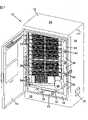
图1为根据本发明的一个电信连接机柜的前视立体图,且打开机柜前部的出入门。Figure 1 is a front perspective view of a telecommunications connection cabinet according to the present invention, with the access door at the front of the cabinet opened.
图2为图1中电信连接机柜的正视图,其中带有举例性的线缆通道。Figure 2 is a front view of the telecommunications connection cabinet of Figure 1 with exemplary cable channels.
图3为图1中电信连接机柜的正视图,且适配器和连接器保持器已取下。Figure 3 is a front view of the telecommunications connection cabinet of Figure 1 with the adapters and connector retainers removed.
图4为图3中电信连接机柜的后视图。FIG. 4 is a rear view of the telecommunications connection cabinet of FIG. 3. FIG.
图5为图1中电信机柜的机架、模块和线缆管理结构从机柜上取下时的前视立体图。FIG. 5 is a front perspective view of the telecommunications cabinet in FIG. 1 when the frame, modules and cable management structure are removed from the cabinet.
图6为图5中机架、模块和线缆管理结构的后视立体图。FIG. 6 is a rear perspective view of the rack, modules and cable management structure of FIG. 5 .
图7为图5中机架、模块和线缆管理结构的正视图。FIG. 7 is a front view of the rack, modules and cable management structure of FIG. 5 .
图8为图5中机架、模块和线缆管理结构的后视图。FIG. 8 is a rear view of the rack, modules and cable management structure of FIG. 5 .
图9为用于图1中电信连接机柜的接合抽屉模块的前视立体图。9 is a front perspective view of a splice drawer module for use in the telecommunications connection cabinet of FIG. 1 .
图10为用于图1所示电信连接机柜的接合抽屉模块的后视立体图。10 is a rear perspective view of a splice drawer module for use in the telecommunications connection cabinet shown in FIG. 1 .
图11为用于图1所示电信连接机柜的输出模块的前视立体图。11 is a front perspective view of an output module for use in the telecommunications connection cabinet shown in FIG. 1 .
图12为用于图1所示电信连接机柜的输出模块的后视立体图。12 is a rear perspective view of an output module for use in the telecommunications connection cabinet shown in FIG. 1 .
图13为用于图1中电信连接机柜的分离器模块或适配器模块的机壳的前视立体图。13 is a front perspective view of a splitter module or adapter module enclosure for the telecommunications connection cabinet of FIG. 1 .
图14为用于图1中电信连接机柜的分离器模块或适配器模块的机壳的后视立体图。14 is a rear perspective view of a splitter module or adapter module enclosure for the telecommunications connection cabinet of FIG. 1 .
图15为根据本发明的光纤连接器保持器的第一立体图。15 is a first perspective view of a fiber optic connector holder according to the present invention.
图16为图15中的光纤连接器保持器的第二立体图。FIG. 16 is a second perspective view of the fiber optic connector holder in FIG. 15 .
图17为图15中的光纤连接器保持器的俯视图。FIG. 17 is a top view of the fiber optic connector holder in FIG. 15 .
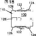
图18为图15中的光纤连接器保持器的仰视图。FIG. 18 is a bottom view of the fiber optic connector holder in FIG. 15 .
图19为图15中的光纤连接器保持器的第一端视图。FIG. 19 is a first end view of the fiber optic connector holder of FIG. 15. FIG.
图20为图15中的光纤连接器保持器的侧视图。FIG. 20 is a side view of the fiber optic connector holder of FIG. 15. FIG.
图21为图15中的光纤连接器保持器的第二相对端视图。FIG. 21 is a second opposite end view of the fiber optic connector holder of FIG. 15. FIG.
图22为一个光纤连接器保持器系统的第一立体图,该系统包含图15中的光纤连接器保持器,且一个光纤连接器插在该光纤连接器保持器内。22 is a first perspective view of a fiber optic connector holder system including the fiber optic connector holder of FIG. 15 with a fiber optic connector inserted within the fiber optic connector holder.
图23为图22中用于保持光纤连接器的所述系统的第二立体图。FIG. 23 is a second perspective view of the system of FIG. 22 for retaining fiber optic connectors.
图24为图22中用于保持光纤连接器的所述系统的俯视图。FIG. 24 is a top view of the system of FIG. 22 for retaining fiber optic connectors.
图25为图22中用于保持光纤连接器的所述系统的侧视图。FIG. 25 is a side view of the system of FIG. 22 for retaining fiber optic connectors.
图26为图22中用于保持光纤连接器的所述系统的端视图。FIG. 26 is an end view of the system of FIG. 22 for retaining fiber optic connectors.
图27为图8中用于保持光纤连接器的所述系统的横截面视图,且沿图25中的A-A线剖开。FIG. 27 is a cross-sectional view of the system for retaining fiber optic connectors in FIG. 8, taken along line A-A in FIG. 25. FIG.
图28为图22中用于保持光纤连接器的所述系统的分解立体图。FIG. 28 is an exploded perspective view of the system of FIG. 22 for retaining fiber optic connectors.
图29为图15中的光纤连接器保持器的主外壳的立体图。29 is a perspective view of the main housing of the fiber optic connector holder in FIG. 15 .
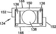
图30为图15中的光纤连接器保持器的内支架的第一立体图。30 is a first perspective view of the inner bracket of the fiber optic connector holder in FIG. 15 .
图31为图30中的内支架的第二立体图。FIG. 31 is a second perspective view of the inner bracket in FIG. 30 .
图32为图30中的内支架的俯视图。Fig. 32 is a top view of the inner bracket in Fig. 30 .
图33为图30中的内支架的侧视图。FIG. 33 is a side view of the inner bracket in FIG. 30 .
图34为图30中的内支架的第一端视图。FIG. 34 is a first end view of the inner bracket of FIG. 30. FIG.
图35为图30中的内支架的第二端视图。FIG. 35 is a second end view of the inner bracket of FIG. 30. FIG.
图36为图15中的光纤连接器保持器的盖板的第一立体图。36 is a first perspective view of the cover plate of the fiber optic connector holder in FIG. 15 .
图37为图36中的盖板的第二立体图。FIG. 37 is a second perspective view of the cover plate in FIG. 36 .
图38为图36中的盖板的俯视图。FIG. 38 is a top view of the cover plate in FIG. 36 .
图39为图36中的盖板的侧视图。FIG. 39 is a side view of the cover plate in FIG. 36 .
图40为图36中的盖板的仰视图。FIG. 40 is a bottom view of the cover plate in FIG. 36 .
图41为图36中的盖板的第一端视图。FIG. 41 is a first end view of the cover plate of FIG. 36. FIG.
图42为图36中的盖板的第二端视图。FIG. 42 is a second end view of the cover plate of FIG. 36. FIG.
图43为图29中的光纤连接器保持器的卡箍的立体图。FIG. 43 is a perspective view of the ferrule of the fiber optic connector holder in FIG. 29 .
图44为图43中的卡箍的端视图。FIG. 44 is an end view of the clip of FIG. 43. FIG.
图45为图43中的卡箍的侧视图。FIG. 45 is a side view of the clip of FIG. 43. FIG.
图46为图43中的卡箍的仰视图。FIG. 46 is a bottom view of the clip in FIG. 43. FIG.
图47为图15中的光纤连接器保持器的俯视图,该光纤连接器保持器插在隔板的一个开口内。Figure 47 is a top view of the fiber optic connector holder of Figure 15 inserted into an opening in the bulkhead.
图48为隔板的立体图,所述隔板包含多个用于容置光纤连接器适配器的开口,并且其中一开口中插着图15中的光纤连接器保持器。FIG. 48 is a perspective view of a partition including a plurality of openings for accommodating fiber optic connector adapters, and one of the openings is inserted with the fiber optic connector holder shown in FIG. 15 .
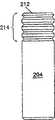
图49为图29中的光纤连接器的防尘帽的立体图。FIG. 49 is a perspective view of the dustproof cap of the optical fiber connector in FIG. 29 .
图50为图49中的防尘帽的侧视图。FIG. 50 is a side view of the dust cap of FIG. 49. FIG.
图51为图49中的防尘帽的端视图。FIG. 51 is an end view of the dust cap of FIG. 49. FIG.
图52为图49中的防尘帽的横截面视图。FIG. 52 is a cross-sectional view of the dust cap of FIG. 49 .
具体实施方式Detailed ways
现在将例示详细描述在附图中示例性地示出的本发明的多个方面。如果可能,在所有附图中相同的附图标记代表相同或相似的部件。Various aspects of the invention, which are exemplarily shown in the accompanying drawings, will now be described in detail by way of example. Wherever possible, the same reference numbers will be used throughout the drawings to refer to the same or like parts.
电信连接机柜,例如图1中所示的机柜10,用于组织或互联各种电信基础线缆。多股式的电信服务线缆,例如具有多根光纤的IFC或带状线缆,可用于电连接或光连接间隔较远的设备。所述服务线缆可以导入机柜10内,在机柜10中,该服务线缆可以连接到一个输出模块34并且分成各根光纤。所述这些股中的每一股可以连接到一条接插线46,该接插线46可以由光纤连接器端接。然后,接插线46的光纤连接器(诸如下面所描述的连接器200)可以插入到一个适配器50的前部内,所述适配器10安装至机柜10中的适配器模块36。A telecommunications connection cabinet, such as the
适配器模块36还可包含一个分离器(spliter),该分离器将来自多达32根单独的接插线46的信号组合至单根光纤线缆内。如图所示,有4个带有分离器的适配器模块36。如图所示,机柜10可有多达4条光纤用以承载多达128条接插线46的信号。这些多达4条的光纤线缆连接到安装在机柜10内的接合模块(splice module)32。这些多达4条的线缆可在接合抽屉32内接合,用于将所述信号传送到其它下游电信设备。The
对于接插线48而言,期望其连接到用于连接下游电信设备的回路,但这不是必需的,这些接插线布设成不连接到连接器保持器模块37。端接接插线48的连接器200连接到一个连接器保持器110。这些接插线48可选地不连接到任何下游设备并存储在连接器保持器110内,并受到保护而免于受损或者弄脏,直到需要时才使用。For
现在参照图1和2,机柜10包括一个机壳12,该机壳12具有一个顶部24、相对两侧部26、一个前壁22和一个底板20。如下图4所示,后壁23与顶部、侧部、前壁和底板配合,以将安装在机壳12中的设备封闭在内部13内。侧部26包含通气开口28,该开口28受到保护,防止雨、雪和灰尘进入内部13。前壁22包含一个前部出入开口16以允许够到安装在内部13中的设备的前部。门14铰接到开口16的一侧,并关闭开口16,以在关闭时封住内部13中的部件。底板20上的线缆入口18允许多股式电信服务线缆进入内部13,并且客户线缆从接合托盘处穿出内部13。尽管图1中示出只有一个开口18,都是可以根据进出机柜10的线缆的尺寸和数量而在底板20上设置更多的开口。Referring now to FIGS. 1 and 2 ,
多个电信设备和支承结构安装在内部13中。如下文将要描述的,内部13包含一个机架安装结构,电信设备安装到该结构上。内部13中的设备包括接合模块32、输出模块24、多个适配器模块36和多个连接器保持器模块37。与所述设备相邻地安装有多个线缆存储卷轴30和弯曲半径保护器42。存储卷轴30和半径保护器42配合,以在安装到内部13中的各种电信设备的前方之间导引线缆。A number of telecommunications equipment and support structures are installed within the interior 13 . As will be described below, interior 13 contains a rack mount structure to which telecommunications equipment is mounted. The equipment in
在内部13中,适配器模块36和连接器保持器模块37包括一个模块机壳,所述模块将在下文描述。模块36和37的各个机壳安装到在机柜10的内部机架安装结构内。多个适配器模块36一起组成工作连接堆叠38,并且多个连接器保持器模块37一起组成存储堆叠40。输出模块34安装到活动连接堆叠38的下方,因为服务线缆从下方穿过开口18进入机柜10。如图所示,机柜10还导引客户线缆穿过底板20,因此接合模块32位于活动连接和存储区域下方。如果服务和/或客户线缆穿过一个贯穿或邻接顶部24的开口进入机柜10,那么输出模块34和接合模块32可位于活动连接和存储区域的上方。Inside 13, the
现在还参照图3和图4,机柜10设置成前部出入式机柜,而且未提供从后壁23进入的结构。在操作现场,技术人员只需从前部开口16操作安装在机柜10中的设备,从而连接或断开一个特定客户的回路。不同设备之间的位于内部13中设备后面的所有连接是不容易够到到的,并且期望在机柜10离开制造厂之前已经预配置并连接好。可选地,若期望有此类出入口,后壁23可设计成带有一个出入门。Referring now also to FIGS. 3 and 4 , the
模块34、36和37包括相对于前壁22倾斜的正面,用于改善线缆在哦线缆管理结构(包括存储卷轴30和半径保护器42)和适配器50以及连接器保持器110之间的定位。
如图3和4中所示,连接器保持器110、适配器50和位于模块36及37中的任一分离器已取下。各个模块36和37的模块机壳56可以相同,并将在下文中进一步描述。如图1和2所示,在七个连接器保持器模块37中的每一个模块包含32个连接器保持器。如图所示,这提供了总计224个连接器200的存储容量。As shown in Figures 3 and 4,
如图所示的输出模块34包含十八个线缆分接器(breakout)54。每个线缆分接器54允许将服务线缆或服务线缆的子单元分成最多12根光纤。这为输出模块34提供了最大容量,来接收多达十八条服务线缆或服务线缆子单元,并且从这些服务线缆分出多达216条接插线46和48。这允许存储区域40中的连接器保持器用于最大数量的接插线46和48中的每条接插线,所述接插线可从输出模块34伸出。The
接插线46和48可由光纤连接器端接,例如由下图22至28中示出的连接器200端接。这些线缆中的光纤可端接于由连接器200中的套圈202所保持的抛光端面,这是本领域技术人员所公知的,并在美国专利5,317,663中公开,该专利在此引入以供参考。这些抛光端面和套圈202需要存储并保护起来,直到需要用于连接到其它光纤线缆或光信号设备。The
通常,一个防尘帽204可套在光纤的抛光端面和套圈202上,以保护所述抛光端面使之免受灰尘、指印或其它可能降低光信号传输性能的物体的污染。尽管已知将这些存储在已知的光纤适配器中,直到所连接线缆中的光纤需要连接到其它光纤线缆或光信号设备,但这种存储不太理想,因为适配器没有像防尘帽204一样密封所述抛光端面使之免遭污染,所述防尘帽204可靠地配合并保持在连接器200的套圈202周围。如果防尘帽204仍然围绕线缆的抛光端面和套圈202放置就位,已知的适配器不允许插入带着该防尘帽204的连接器200。Typically, a
现在参照图15和16,连接器保持器110包含一个形成一个内腔114的主外壳112。一个开口端118允许连接器200插入内腔114中,而对侧开口116允许防尘帽204从连接器保持器10伸出。一个卡箍120环绕主外壳112放置并包含一对弹性安装夹片122。一对凸缘124邻近弹性夹片122并从主外壳112的相对两侧126延伸。如下图所示,夹片122和凸缘124相配合以如图所示将保持器10可释放地安装在隔板上的一个开口内。Referring now to FIGS. 15 and 16 , the
主外壳112还包括一个底部130,底部130带有键槽128以容置连接器200的键形延伸部分,而使连接器200以一致的方向插入内腔114中。与底部130相对的是一个开放顶部,其由一块盖板132盖住。下图26中更详细地显示相关细节。图17至21为连接器保持器110的其它视图。The
现在参照图22至27,示出了连接器100带有位于内腔118内的连接器200。当连接器200插入并穿过开口端114时,防尘帽204从连接器保持器110的开口116伸出。Referring now to FIGS. 22 to 27 , the connector 100 is shown with the
现在参照图27和28,连接器保持器110还包含一个内支架134,内支架134带有一对相对的可释放式的卡钩136和一个尺寸适合容置防尘帽204的开口138。内支架134穿过开放顶部140而放置在主外壳112内,开放顶部140的开口138靠近开口116,并且卡钩136靠近开口端114。接着,盖板132放置在开放顶部140上并且卡箍120环绕盖板132和主外壳112设置。盖板132可用胶接、超声焊接或其它各种已知的紧固技术密封在开放顶部140内。连接器200包含一对相对的凹槽206,凹槽206用于在连接器200插入保持器110时容置卡钩136。Referring now to FIGS. 27 and 28 , the
如图所示,连接器200和保持器110为SC型。连接器200和保持器110可遵循其它类型或制式的电子连接器或适配器而不会偏离本发明的精神。As shown,
现在参照图29,主外壳112还包含沿着内腔114两侧的槽142,所述槽142用于在内腔114内容纳及放置内支架134的突出部分。沿侧面126设置一凹陷区域144以容置卡箍120。开放顶部140包含一凸缘146,盖板132设置在凸缘146上以关闭内腔114。一外部隔板168形成开口116的一部分。一内部隔板145与外部隔板168隔开放置并且这些隔板相互配合而形成槽142。在隔板145与168之间是形成所述槽142底部的定位面143。Referring now to FIG. 29 , the
现在参照图30至35,内支架134包含一对从横梁150延伸的卡臂148。用于容置连接器200的防尘帽204的开口138位于横梁150上。卡钩136位于卡臂148与横梁150相对的端部处。横梁150包含一对容置于主外壳112的槽142内的凸缘152。如图32所示,卡钩136包含一个斜面部分154,当连接器200穿过连接器保持器110的开口端118而插入到内腔114中时,该斜面部分154由连接器200接合。卡臂148向外倾斜允许连接器200穿过卡钩136。当连接器200完全插入内腔114后(如图27所示),卡钩136容置于凹槽206内,并且每个卡钩136的保持表面156将连接器200保持在内腔114内。Referring now to FIGS. 30-35 , the
内支架134设置成允许以两个取向中的任意一个插入主外壳112内腔114的槽142中。横梁150的一对边缘166将内支架相对于盖板132和主外壳112正确地定位在内腔114内,从而校准开口138以容置防尘帽204。The
现在参照图36至42,盖板132包含一个沿着外部表面168用于容置卡箍120的凹陷区域158。在外部表面168上还有一个用于容置标贴的凹陷区域172。沿着内部表面170形成的一对边缘164设置成容置在主外壳112的凸缘146上。外部凸缘160从内部表面170延伸,且与主外壳112内的隔板168相配合形成开116。还有一内部凸缘162从内部表面170伸出,且与凸缘160间隔开而形成槽163。槽163与主外壳112的槽142配合以容置内支架134的凸缘152。Referring now to FIGS. 36-42 ,
在槽163顶部处的是定位面161,定位面161与内支架134的一个边缘166配合而将内支架134定位在内腔114中,使得内支架134的开口138与开116对齐。当组装成连接器保持器110时,主外壳112的定位面143及盖板132的定位面161相配合而接合内支架134的两边缘166。主外壳112的槽142和盖板132的槽163配合以卡住内支架134的凸缘152。At the top of the
现在参照图43至46,卡箍120包含一横梁174和一对相对的侧部176。在侧部176上形成有弹性夹片122。侧部176容置于主外壳112的凹陷区域144内,并且横梁174容置于盖板132的凹陷区域158内。可以设想,卡箍120由弹性可变形的金属制成以方便从隔板的开口插入或取下。弹性夹片122各包含一个端部178和一个斜面180。Referring now to FIGS. 43-46 , the
图47和48示出插入在隔板182的开口184之内的光纤连接器保持器110。隔板182可以是诸如安装板之类的电信交换设备零部件的一个部分,隔板182用于在多根光纤之间或在连接器保持器模块37中形成多个连接,如图48所示,该隔板包含多个用于适配器的开口84。可选地,在只需要单个光纤连接器保持器110的场合,隔板182可只包含单个开口184。47 and 48 illustrate the fiber
连接器保持器110的开口端118穿过开口184插入,直到开口184的一对侧面186与弹性夹片122的斜面180接合。继续插入连接器保持器110将使得隔板侧面186向内朝着侧面126压下弹性夹片122。最终,隔板侧面186将穿过弹性夹片122的端部178。接着,弹性夹片122将弹回,如图48所示,从而将隔板侧面186卡在端部178和凸缘124之间。通过压下弹性夹片122并以与上述插入时相反的方向取下,可以将连接器保持器110从开口184取下。The open end 118 of the
可选地,凸缘124可设置成包含一紧固件开口,从而,连接器保持器110能由可拆卸的紧固件安装在开口184内。Optionally,
可以想象,用于安装适配器和连接器保持器的开口184可包含在滑动式适配器组件中,如本申请人为共同拥有人的美国专利5,497,444中所述。该专利所公开的内容在此引入以供参考。It is conceivable that
现在参照图49至52,防尘帽204包含一中央开口208,该开口208用于在套圈202穿过开口端210时容置套圈202。与开口端210相对的是封闭端212,封闭端212包含滚花214,从而可更好地抓牢防尘帽204便于取下。中央开口208绕套圈202而与之配合,以绕套圈提供一个密封并将防尘帽保持到连接器200。当插入套圈202时(如图27),由于减少了中央开口208内的空气体积,一个或多个螺旋形凹槽216沿内壁218设置在中央开口208内。凹槽216从封闭端212附近一直延伸到开口端210。凹槽216足够小能防止有害污物进入,并且,当套圈202插入时,还允许中央开口208内的空气排出,从而防尘帽204能够完全密封连接器200。当防尘帽204从套圈202取下时,凹槽216还允许空气进入中央开口208。每个凹槽216的形状还设计成当防尘帽204从套圈202上取下或放置在套圈202上时,允许空气进出中央开口208,同时禁止污物沿相同通道进出。Referring now to FIGS. 49-52 ,
现在参照图5至8,示出了不带机壳12的机柜10。与机壳12的侧部26相邻的一对竖直支承件51和52为安装在机柜10中的设备提供安装位置。一线缆管理安装板58安装在竖直支承件51上,并且多个存储卷轴30安装到安装板58上。与安装板58相邻的各个模块机壳56上安装有弯曲半径保护器42,弯曲半径保护器42为从存储卷轴30延伸到模块36或37的线缆46和48提供弯曲半径保护。Referring now to FIGS. 5-8 , the
一线缆夹60安装到输出模块34的后部,用于在服务线缆穿过底板20的开口18进入机柜10之后固定服务线缆。服务线缆、服务线缆的子单元或更小的光纤束可从线缆夹60开始穿过后部开口62进入输出模块34。在安装到安装板58的存储卷轴30之外,另一个存储卷轴30安装到输出模块34的前部,用于提供半径保护功能并将接插线46和48从线缆分接器54导引到安装板58的线缆存储卷轴30以及模块36、37的半径保护器42。A cable clip 60 is mounted to the rear of the
现在参照图9和10,接合模块32包含一可滑动地安装在机壳66内的接合抽屉64。接合模块机壳66包含一对安装凸缘72和74,安装凸缘72和74用于将接合模块32安装到安装板58和竖直支承件52上。抽屉64上有一个锁住抽屉的闩销68,用于防止有害地或意外地操作接合模块32中的接头。设置一后部开口70以允许线缆从模块36进入机壳66并在抽屉64内连接。Referring now to FIGS. 9 and 10 , the
现在参照图11和12,输出模块34包含一个正面(front face),正面上安装十八个线缆分接器54。输出模块34还包含一个用于安装到安装板58上的凸缘72和一个用于安装到竖直支承件52上的凸缘74。Referring now to Figures 11 and 12, the
现在参照图13和14,模块机壳56为适配器模块36和连接器保持器模块37提供基本外壳。机壳56包括一个带四个开口84的正面84。开口84的尺寸和构造设置成可以容置多达八个的适配器50或连接器保持器110,从而总共可以容纳三十二条接插线46或48。这些适配器50或连接器保持器110可由保持器夹保持在开口84内,例如由本申请人为共同拥有人的美国专利5,214,735所公开的保持器夹来保持,在此引入该专利所公开的内容以供参考。模块机壳56还定义了一个内部空间86,在侧壁78上有一个线缆出口80。当模块机壳56用于适配器模块36时,安装在开口84内的每个适配器50可以有一个连接器200插在后壁上,该连接器200将与插入到前侧的接插线46的连接器200光连接。后面的这些连接器200可以端接光纤线缆,从而光纤线缆可延伸穿过线缆出口80。Referring now to FIGS. 13 and 14 , the
可选地,适配器模块36可包含一个位于内部空间86内的分离器。接着,连接到各适配器50后部的连接器200将与该分离器光连接。从一个给定的模块36中的各个适配器50来的信号由该分离器组合至单根光纤线缆内,然后该该光纤线缆可以从线缆出口80穿出模块36,并到达接合模块32的后部开口70。在接合模块32内,每个承载来自于连接到模块36的多达32个适配器的接插线46的组合信号的线缆可以接合到另一条线缆,用于将信号分配到下游的设备或用户。Optionally,
如图所示,机柜10设计成只从正面进出,因为后壁23上没有提供出入开口。可以设想采用其它配置的机壳12用于机柜10,该配置可为内部13提供另外的出入口。一种优选的在机柜10内连接光纤服务线缆的方法减少了对安装在机壳12内设备的后部进行操作的需要。As shown, the
为了将服务线缆连接在机柜10内,所述服务线缆通过底板20的开口18进入机柜10。将该服务线缆导引到位于安装在竖直支承件51、52上的设备以及后壁23之间的空间内,然后用线缆夹60夹到输出模块34的后部。在线缆夹60处,线缆可分成子单元并被导引穿过开口62进入输出模块34的内部61。在内部61中,线缆的子单元进一步分成导引到线缆分接器54的单个光纤,在此处所述光纤穿出内部61,并且优选地,接到(up-iacketed to)由连接器200端接的标准接插线46或48。期望接插线46和48为标准尺寸的接插线,例如1.7mm、2.0mm或其它适合在机柜10内布设的尺寸。In order to connect service cables inside the
接插线46和48从分接器54处导引到安装在输出模块34上的存储卷轴30,并导引到安装在安装板58上的存储卷轴30。接插线46和48从这些存储卷轴穿过半径保护器42以及分别插在适配器50和连接器保持器100中的连接器200。如上所述,接插线46通过适配器模块36的内部86中的适配器50和可能的分离器而光连接到接合模块32,然后连接到下游设备。如上所述,接插线48存储在连接器保持器110以用于未来的使用,其上带有防尘帽104以保护抛光端面使之免于受损或弄脏。
当一根存储或待用接插线48需要连接到下游设备时,例如当一个新的客户请求服务或一个已有的客户需要扩展业务时,所需的待用接插线48从连接器保持器110上取下。从连接器200的套圈102上取下防尘帽104,从安装到安装板58的存储卷轴30上部分地取下接插线48。接着该接插线重新布设,使得其连接器200靠近用于连接到下游设备的所需适配器50。此时,先前的待用接插线48已变成一工作接插线46,并插入合适的适配器50内。当客户或其它下游设备不再需要先前所要求的回路时,通过反过来进行以上过程,可将一工作接插线46转换为一待用接插线48。When a storage or
通过如上所述地配置机柜10,在操作现场,技术人员只需要通过出入开口16从前部对所述机柜进行操作将可为新客户或已有客户连接一条回路或者断开一条回路。By configuring the
上述说明、例子和数据提供对包含本发明的各组成部分的制造和使用提供了完整说明。由于在本发明的精神和范围内而可得到本发明的多种实现方式,所以本发明的保护范围由附带的权利要求来限定。The above specification, examples and data provide a complete description of the manufacture and use of the composition comprising the invention. Since many implementations of the invention are possible within the spirit and scope of the invention, the scope of protection of the invention is defined by the appended claims.
Claims (18)
Applications Claiming Priority (2)
| Application Number | Priority Date | Filing Date | Title |
|---|---|---|---|
| US10/613,764 | 2003-07-02 | ||
| US10/613,764US7233731B2 (en) | 2003-07-02 | 2003-07-02 | Telecommunications connection cabinet |
Related Child Applications (1)
| Application Number | Title | Priority Date | Filing Date |
|---|---|---|---|
| CN2009102058379ADivisionCN101677412B (en) | 2003-07-02 | 2004-06-18 | Telecommunications connection cabinet and method for connecting telecommunications cabinets |
Publications (2)
| Publication Number | Publication Date |
|---|---|
| CN1817050Atrue CN1817050A (en) | 2006-08-09 |
| CN100566433C CN100566433C (en) | 2009-12-02 |
Family
ID=33552761
Family Applications (2)
| Application Number | Title | Priority Date | Filing Date |
|---|---|---|---|
| CNB200480018908XAExpired - Fee RelatedCN100566433C (en) | 2003-07-02 | 2004-06-18 | Fiber optic cable distribution frame |
| CN2009102058379AExpired - Fee RelatedCN101677412B (en) | 2003-07-02 | 2004-06-18 | Telecommunications connection cabinet and method for connecting telecommunications cabinets |
Family Applications After (1)
| Application Number | Title | Priority Date | Filing Date |
|---|---|---|---|
| CN2009102058379AExpired - Fee RelatedCN101677412B (en) | 2003-07-02 | 2004-06-18 | Telecommunications connection cabinet and method for connecting telecommunications cabinets |
Country Status (12)
| Country | Link |
|---|---|
| US (15) | US7233731B2 (en) |
| EP (2) | EP1639840B1 (en) |
| JP (1) | JP4511530B2 (en) |
| KR (1) | KR101118806B1 (en) |
| CN (2) | CN100566433C (en) |
| AT (1) | ATE543340T1 (en) |
| AU (2) | AU2004300877B2 (en) |
| CA (1) | CA2530885A1 (en) |
| ES (2) | ES2381671T3 (en) |
| MX (1) | MXPA06000222A (en) |
| TW (1) | TWI406623B (en) |
| WO (1) | WO2005006783A2 (en) |
Cited By (5)
| Publication number | Priority date | Publication date | Assignee | Title |
|---|---|---|---|---|
| CN101627637A (en)* | 2007-03-09 | 2010-01-13 | Adc电信公司 | Telecommunication rack unit tray |
| CN101384937B (en)* | 2006-02-13 | 2012-04-25 | Adc电信公司 | Fiber distribution hub with swing frame and modular termination panels |
| CN108594384A (en)* | 2011-10-07 | 2018-09-28 | Adc电信公司 | Fiber termination box, system and method |
| CN109154706A (en)* | 2016-03-15 | 2019-01-04 | 康宁研究与开发公司 | High-density dispensing frame with integrated splice compartment |
| CN110426802A (en)* | 2019-08-26 | 2019-11-08 | 上海天诚通信技术股份有限公司 | Novel wire distribution rack with Quick Release bracket |
Families Citing this family (229)
| Publication number | Priority date | Publication date | Assignee | Title |
|---|---|---|---|---|
| US6760531B1 (en) | 1999-03-01 | 2004-07-06 | Adc Telecommunications, Inc. | Optical fiber distribution frame with outside plant enclosure |
| US7142764B2 (en)* | 2003-03-20 | 2006-11-28 | Tyco Electronics Corporation | Optical fiber interconnect cabinets, termination modules and fiber connectivity management for the same |
| US7198409B2 (en)* | 2003-06-30 | 2007-04-03 | Adc Telecommunications, Inc. | Fiber optic connector holder and method |
| US7233731B2 (en)* | 2003-07-02 | 2007-06-19 | Adc Telecommunications, Inc. | Telecommunications connection cabinet |
| US6885798B2 (en) | 2003-09-08 | 2005-04-26 | Adc Telecommunications, Inc. | Fiber optic cable and furcation module |
| US7369741B2 (en)* | 2003-11-17 | 2008-05-06 | Fiber Optics Network Solutions Corp. | Storage adapter with dust cap posts |
| US6983095B2 (en)* | 2003-11-17 | 2006-01-03 | Fiber Optic Network Solutions Corporation | Systems and methods for managing optical fibers and components within an enclosure in an optical communications network |
| CA2471175A1 (en)* | 2004-06-16 | 2005-12-16 | Martin Bijman | Apparatus for optical cable management in telecommunications cabinets |
| US7218827B2 (en) | 2004-06-18 | 2007-05-15 | Adc Telecommunications, Inc. | Multi-position fiber optic connector holder and method |
| US7376321B2 (en)* | 2004-08-09 | 2008-05-20 | Adc Telecommunications, Inc. | Modules including multiple rows of adapters for high density optical fiber distribution frame |
| US7489849B2 (en) | 2004-11-03 | 2009-02-10 | Adc Telecommunications, Inc. | Fiber drop terminal |
| US7376322B2 (en) | 2004-11-03 | 2008-05-20 | Adc Telecommunications, Inc. | Fiber optic module and system including rear connectors |
| US7167628B2 (en) | 2004-12-13 | 2007-01-23 | Adc Telecommunications, Inc. | Service blocker device and method |
| US7260302B2 (en)* | 2005-02-16 | 2007-08-21 | Panduit Corp. | Patch cord management system |
| DE102005011208A1 (en)* | 2005-03-09 | 2006-09-21 | Adc Gmbh | Fiber optic cable termination |
| US7194181B2 (en) | 2005-03-31 | 2007-03-20 | Adc Telecommunications, Inc. | Adapter block including connector storage |
| WO2006135524A2 (en)* | 2005-05-18 | 2006-12-21 | Corning Cable Systems Llc | High density optical fiber distribution enclosure |
| US7376323B2 (en)* | 2005-05-25 | 2008-05-20 | Adc Telecommunications, Inc. | Fiber optic adapter module |
| US7400813B2 (en) | 2005-05-25 | 2008-07-15 | Adc Telecommunications, Inc. | Fiber optic splitter module |
| US7349619B2 (en) | 2005-05-25 | 2008-03-25 | Adc Telecommunications, Inc. | Fiber service blocker |
| US7636507B2 (en)* | 2005-06-17 | 2009-12-22 | Adc Telecommunications, Inc. | Compact blind mateable optical splitter |
| US7583883B2 (en)* | 2005-07-26 | 2009-09-01 | Adc Telecommunications, Inc. | Fiber optic connector holder |
| WO2007019454A1 (en)* | 2005-08-05 | 2007-02-15 | Corning Cable Systems Llc | Parking device for fiber distribution hub |
| US7643631B2 (en)* | 2005-08-26 | 2010-01-05 | Adc Telecommunications, Inc. | Enclosure for broadband service delivery system |
| US7346254B2 (en)* | 2005-08-29 | 2008-03-18 | Adc Telecommunications, Inc. | Fiber optic splitter module with connector access |
| US7623749B2 (en)* | 2005-08-30 | 2009-11-24 | Adc Telecommunications, Inc. | Fiber distribution hub with modular termination blocks |
| US7330626B2 (en)* | 2005-08-31 | 2008-02-12 | Adc Telecommunications, Inc. | Cabinet including optical bulkhead plate for blown fiber system |
| US7190874B1 (en) | 2005-10-03 | 2007-03-13 | Adc Telecommunications, Inc. | Fiber demarcation box with cable management |
| US7245809B1 (en)* | 2005-12-28 | 2007-07-17 | Adc Telecommunications, Inc. | Splitter modules for fiber distribution hubs |
| US7816602B2 (en) | 2006-02-13 | 2010-10-19 | Adc Telecommunications, Inc. | Fiber distribution hub with outside accessible grounding terminals |
| US7418181B2 (en) | 2006-02-13 | 2008-08-26 | Adc Telecommunications, Inc. | Fiber optic splitter module |
| WO2007101275A1 (en)* | 2006-03-03 | 2007-09-07 | Honeywell International, Inc. | Camera with auto-focus capability |
| US7760984B2 (en)* | 2006-05-04 | 2010-07-20 | Adc Telecommunications, Inc. | Fiber distribution hub with swing frame and wrap-around doors |
| EP2363739A3 (en)* | 2006-06-21 | 2011-09-21 | Firecomms Limited | An optical connector |
| MX2009001629A (en)* | 2006-08-21 | 2009-02-23 | Afl Telecommunications Llc | Fiber distribution hub. |
| US7711234B2 (en) | 2006-10-02 | 2010-05-04 | Adc Telecommunications, Inc. | Reskinnable fiber distribution hub |
| US7583885B2 (en)* | 2006-11-28 | 2009-09-01 | Adc Telecommunications, Inc. | Fiber distribution enclosure |
| US7496268B2 (en)* | 2006-12-13 | 2009-02-24 | Corning Cable Systems Llc | High density fiber optic hardware |
| US7916988B2 (en)* | 2006-12-22 | 2011-03-29 | Verizon Services Corp. | Optical splitter assembly |
| US7349616B1 (en) | 2007-01-12 | 2008-03-25 | Corning Cable Systems Llc | Fiber optic local convergence points for multiple dwelling units |
| US7822310B2 (en)* | 2007-02-28 | 2010-10-26 | Corning Cable Systems Llc | Fiber optic splice trays |
| US7522805B2 (en)* | 2007-03-09 | 2009-04-21 | Adc Telecommunications, Inc. | Wall mount distribution arrangement |
| US7715679B2 (en)* | 2007-05-07 | 2010-05-11 | Adc Telecommunications, Inc. | Fiber optic enclosure with external cable spool |
| US7471867B2 (en)* | 2007-05-15 | 2008-12-30 | Commscope Inc. Of North Carolina | Fiber optic splice and distribution enclosure |
| US7734138B2 (en)* | 2007-05-30 | 2010-06-08 | Corning Cable Systems Llc | Fiber optic connector holders |
| US7391954B1 (en) | 2007-05-30 | 2008-06-24 | Corning Cable Systems Llc | Attenuated optical splitter module |
| US20080298743A1 (en)* | 2007-05-31 | 2008-12-04 | Konstantinos Saravanos | Microsplitter module for optical connectivity |
| US20080298748A1 (en)* | 2007-05-31 | 2008-12-04 | Terry Dean Cox | Direct-connect optical splitter module |
| US7756379B2 (en) | 2007-08-06 | 2010-07-13 | Adc Telecommunications, Inc. | Fiber optic enclosure with internal cable spool |
| US8798427B2 (en) | 2007-09-05 | 2014-08-05 | Corning Cable Systems Llc | Fiber optic terminal assembly |
| US7720344B2 (en)* | 2007-10-22 | 2010-05-18 | Adc Telecommunications, Inc. | Fiber distribution hub |
| WO2009058928A1 (en)* | 2007-10-30 | 2009-05-07 | The Siemon Company | Vertical patching system |
| US7751672B2 (en) | 2007-10-31 | 2010-07-06 | Adc Telecommunications, Inc. | Low profile fiber distribution hub |
| US7860365B2 (en)* | 2007-11-16 | 2010-12-28 | Adc Telecommunications, Inc. | Edge protector for fiber optic cable routing |
| US8229265B2 (en)* | 2007-11-21 | 2012-07-24 | Adc Telecommunications, Inc. | Fiber distribution hub with multiple configurations |
| US8238709B2 (en) | 2007-12-18 | 2012-08-07 | Adc Telecommunications, Inc. | Multi-configuration mounting system for fiber distribution hub |
| US7715682B2 (en)* | 2008-03-04 | 2010-05-11 | Adc Telecommunications, Inc. | Fiber distribution hub having an adjustable plate |
| US7889961B2 (en) | 2008-03-27 | 2011-02-15 | Corning Cable Systems Llc | Compact, high-density adapter module, housing assembly and frame assembly for optical fiber telecommunications |
| CN101553095B (en)* | 2008-04-03 | 2011-08-31 | 3M创新有限公司 | Embedded communication equipment box |
| US7903922B2 (en)* | 2008-08-07 | 2011-03-08 | Fujikura Ltd. | Optical connector holder and optical termination cabinet, and method of optical fiber wiring in optical termination cabinet |
| ES2560802T3 (en) | 2008-08-27 | 2016-02-22 | Adc Telecommunications, Inc. | Fiber optic adapter with integrally molded bushing alignment structure |
| US8452148B2 (en) | 2008-08-29 | 2013-05-28 | Corning Cable Systems Llc | Independently translatable modules and fiber optic equipment trays in fiber optic equipment |
| US11294136B2 (en) | 2008-08-29 | 2022-04-05 | Corning Optical Communications LLC | High density and bandwidth fiber optic apparatuses and related equipment and methods |
| CN102209921B (en) | 2008-10-09 | 2015-11-25 | 康宁光缆系统有限公司 | There is the fibre-optic terminus supported from the adapter panel of the input and output optical fiber of optical splitters |
| US8879882B2 (en) | 2008-10-27 | 2014-11-04 | Corning Cable Systems Llc | Variably configurable and modular local convergence point |
| US8224144B2 (en) | 2008-10-31 | 2012-07-17 | Tyco Electronics Corporation | Fiber optic connector storage apparatus and methods for using the same |
| WO2010059623A1 (en) | 2008-11-21 | 2010-05-27 | Adc Telecommunications, Inc. | Fiber optic telecommunications module |
| US8363997B2 (en)* | 2008-12-19 | 2013-01-29 | Commscope, Inc. Of North Carolina | System for intelligent patching of telecommunication cables with a communication network |
| US8380036B2 (en)* | 2009-01-20 | 2013-02-19 | Adc Telecommunications, Inc. | Splitter module with connectorized pigtail manager |
| EP2221932B1 (en) | 2009-02-24 | 2011-11-16 | CCS Technology Inc. | Holding device for a cable or an assembly for use with a cable |
| US20100220967A1 (en)* | 2009-02-27 | 2010-09-02 | Cooke Terry L | Hinged Fiber Optic Module Housing and Module |
| CN106130646B (en) | 2009-03-05 | 2019-04-30 | Adc电信公司 | Methods, systems and apparatus for integrating wireless technologies into fiber optic networks |
| EP2237091A1 (en)* | 2009-03-31 | 2010-10-06 | Corning Cable Systems LLC | Removably mountable fiber optic terminal |
| GB2470184B (en)* | 2009-05-11 | 2015-01-07 | Connectix Ltd | Patch panel |
| US8699838B2 (en) | 2009-05-14 | 2014-04-15 | Ccs Technology, Inc. | Fiber optic furcation module |
| US9075216B2 (en) | 2009-05-21 | 2015-07-07 | Corning Cable Systems Llc | Fiber optic housings configured to accommodate fiber optic modules/cassettes and fiber optic panels, and related components and methods |
| US8538226B2 (en)* | 2009-05-21 | 2013-09-17 | Corning Cable Systems Llc | Fiber optic equipment guides and rails configured with stopping position(s), and related equipment and methods |
| US7899300B2 (en)* | 2009-06-03 | 2011-03-01 | Emerson Network Power, Energy Systems, North America, Inc. | Dust caps for fiber optic connectors |
| US8244089B2 (en)* | 2009-06-03 | 2012-08-14 | Emerson Network Power, Energy Systems, North America, Inc. | Dust caps for fiber optic connectors |
| EP2443497B1 (en) | 2009-06-19 | 2020-03-04 | Corning Cable Systems LLC | High density and bandwidth fiber optic apparatus |
| WO2010148325A1 (en) | 2009-06-19 | 2010-12-23 | Corning Cable Systems Llc | High fiber optic cable packing density apparatus |
| US8712206B2 (en) | 2009-06-19 | 2014-04-29 | Corning Cable Systems Llc | High-density fiber optic modules and module housings and related equipment |
| ES2403007A1 (en)* | 2009-07-01 | 2013-05-13 | Adc Telecommunications, Inc | Wall-mounted fiber distribution hub |
| US8374478B2 (en)* | 2009-07-17 | 2013-02-12 | Adc Telecommunications, Inc. | Fiber optic dust cap and connector for terminating multi-fiber optical cables |
| US8606067B2 (en)* | 2009-09-04 | 2013-12-10 | Adc Telecommunications, Inc. | Pedestal terminal with swing frame |
| US8428419B2 (en)* | 2009-09-23 | 2013-04-23 | Adc Telecommunications, Inc. | Fiber distribution hub with internal cable spool |
| US8467651B2 (en)* | 2009-09-30 | 2013-06-18 | Ccs Technology Inc. | Fiber optic terminals configured to dispose a fiber optic connection panel(s) within an optical fiber perimeter and related methods |
| US8625950B2 (en) | 2009-12-18 | 2014-01-07 | Corning Cable Systems Llc | Rotary locking apparatus for fiber optic equipment trays and related methods |
| WO2011088202A1 (en) | 2010-01-18 | 2011-07-21 | Adc Telecommunications, Inc. | Fiber distribution enclosure |
| US8262294B2 (en)* | 2010-02-04 | 2012-09-11 | Adc Telecommunications, Inc. | Fiber optic dust cap and connector for terminating multi-fiber optical cables |
| US8992099B2 (en) | 2010-02-04 | 2015-03-31 | Corning Cable Systems Llc | Optical interface cards, assemblies, and related methods, suited for installation and use in antenna system equipment |
| CN102870021B (en) | 2010-03-02 | 2015-03-11 | 蒂安电子服务有限责任公司 | Fibre-optic telecommunication module |
| US8649649B2 (en) | 2010-03-03 | 2014-02-11 | Adc Telecommunications, Inc. | Fiber distribution hub with connectorized stub cables |
| US9547144B2 (en) | 2010-03-16 | 2017-01-17 | Corning Optical Communications LLC | Fiber optic distribution network for multiple dwelling units |
| US20110235986A1 (en)* | 2010-03-24 | 2011-09-29 | Adc Telecommunications, Inc. | Optical fiber drawer with connectorized stub cable |
| US8913866B2 (en) | 2010-03-26 | 2014-12-16 | Corning Cable Systems Llc | Movable adapter panel |
| US9078287B2 (en) | 2010-04-14 | 2015-07-07 | Adc Telecommunications, Inc. | Fiber to the antenna |
| US8837940B2 (en) | 2010-04-14 | 2014-09-16 | Adc Telecommunications, Inc. | Methods and systems for distributing fiber optic telecommunication services to local areas and for supporting distributed antenna systems |
| CA2796221C (en) | 2010-04-16 | 2018-02-13 | Ccs Technology, Inc. | Sealing and strain relief device for data cables |
| US8792767B2 (en) | 2010-04-16 | 2014-07-29 | Ccs Technology, Inc. | Distribution device |
| EP2381284B1 (en) | 2010-04-23 | 2014-12-31 | CCS Technology Inc. | Under floor fiber optic distribution device |
| US9239442B2 (en) | 2010-04-27 | 2016-01-19 | Adc Communications (Shanghai) Co., Ltd. | Fiber optic module and chassis |
| US8660397B2 (en) | 2010-04-30 | 2014-02-25 | Corning Cable Systems Llc | Multi-layer module |
| US9632270B2 (en) | 2010-04-30 | 2017-04-25 | Corning Optical Communications LLC | Fiber optic housings configured for tool-less assembly, and related components and methods |
| US8879881B2 (en) | 2010-04-30 | 2014-11-04 | Corning Cable Systems Llc | Rotatable routing guide and assembly |
| US8705926B2 (en) | 2010-04-30 | 2014-04-22 | Corning Optical Communications LLC | Fiber optic housings having a removable top, and related components and methods |
| US9519118B2 (en) | 2010-04-30 | 2016-12-13 | Corning Optical Communications LLC | Removable fiber management sections for fiber optic housings, and related components and methods |
| US9720195B2 (en) | 2010-04-30 | 2017-08-01 | Corning Optical Communications LLC | Apparatuses and related components and methods for attachment and release of fiber optic housings to and from an equipment rack |
| US9075217B2 (en) | 2010-04-30 | 2015-07-07 | Corning Cable Systems Llc | Apparatuses and related components and methods for expanding capacity of fiber optic housings |
| WO2011140461A2 (en) | 2010-05-07 | 2011-11-10 | Adc Telecommunications, Inc. | Fiber distribution hub with pass-through interfaces |
| US9377597B2 (en)* | 2010-06-02 | 2016-06-28 | Commscope Technologies Llc | Aggregator for a switch rack system |
| EP2400775B1 (en)* | 2010-06-22 | 2014-01-15 | 3M Innovative Properties Co. | Support structure for telecommunication jacks |
| CN102346279B (en)* | 2010-07-30 | 2015-03-11 | 株式会社藤仓 | Optical connector and connector connection system |
| US8441780B2 (en) | 2010-08-25 | 2013-05-14 | Itron, Inc. | Utility-grade enclosure for incorporation of network communication devices |
| US8880765B2 (en) | 2010-08-25 | 2014-11-04 | Itron, Inc. | Interface bus for utility-grade network communication devices |
| US8718436B2 (en) | 2010-08-30 | 2014-05-06 | Corning Cable Systems Llc | Methods, apparatuses for providing secure fiber optic connections |
| WO2012054454A2 (en) | 2010-10-19 | 2012-04-26 | Corning Cable Systems Llc | Transition box for multiple dwelling unit fiber optic distribution network |
| US9279951B2 (en) | 2010-10-27 | 2016-03-08 | Corning Cable Systems Llc | Fiber optic module for limited space applications having a partially sealed module sub-assembly |
| WO2012058391A1 (en) | 2010-10-28 | 2012-05-03 | Corning Cable Systems Llc | Impact resistant fiber optic enclosures and related methods |
| US8662760B2 (en) | 2010-10-29 | 2014-03-04 | Corning Cable Systems Llc | Fiber optic connector employing optical fiber guide member |
| US9116324B2 (en) | 2010-10-29 | 2015-08-25 | Corning Cable Systems Llc | Stacked fiber optic modules and fiber optic equipment configured to support stacked fiber optic modules |
| US8494332B2 (en) | 2010-11-15 | 2013-07-23 | Adc Telecommunications, Inc. | Tray assembly for a fiber optic enclosure |
| CA2819235C (en) | 2010-11-30 | 2018-01-16 | Corning Cable Systems Llc | Fiber device holder and strain relief device |
| JP2012123056A (en)* | 2010-12-06 | 2012-06-28 | Hitachi Ltd | Housing for communication |
| US8873922B2 (en) | 2010-12-20 | 2014-10-28 | Adc Telecommunications, Inc. | Fan-out and parking module |
| WO2012106510A2 (en) | 2011-02-02 | 2012-08-09 | Corning Cable Systems Llc | Dense fiber optic connector assemblies and related connectors and cables suitable for establishing optical connections for optical backplanes in equipment racks |
| US9182563B2 (en) | 2011-03-31 | 2015-11-10 | Adc Telecommunications, Inc. | Adapter plate for fiber optic module |
| US9008485B2 (en) | 2011-05-09 | 2015-04-14 | Corning Cable Systems Llc | Attachment mechanisms employed to attach a rear housing section to a fiber optic housing, and related assemblies and methods |
| AU2012275598A1 (en) | 2011-06-30 | 2014-01-16 | Corning Optical Communications LLC | Fiber optic equipment assemblies employing non-U-width-sized housings and related methods |
| US8953924B2 (en) | 2011-09-02 | 2015-02-10 | Corning Cable Systems Llc | Removable strain relief brackets for securing fiber optic cables and/or optical fibers to fiber optic equipment, and related assemblies and methods |
| WO2013033890A1 (en) | 2011-09-06 | 2013-03-14 | Adc Telecommunications, Inc. | Adapter for fiber optic module |
| US9417418B2 (en) | 2011-09-12 | 2016-08-16 | Commscope Technologies Llc | Flexible lensed optical interconnect device for signal distribution |
| US8768136B2 (en)* | 2011-09-13 | 2014-07-01 | Yazaki North America, Inc. | Fiber optic connector/dust cover organizer |
| US9069151B2 (en) | 2011-10-26 | 2015-06-30 | Corning Cable Systems Llc | Composite cable breakout assembly |
| US9038832B2 (en) | 2011-11-30 | 2015-05-26 | Corning Cable Systems Llc | Adapter panel support assembly |
| US9219546B2 (en) | 2011-12-12 | 2015-12-22 | Corning Optical Communications LLC | Extremely high frequency (EHF) distributed antenna systems, and related components and methods |
| EP2795811B1 (en) | 2011-12-22 | 2018-08-22 | CommScope Technologies LLC | Fiber optic wall plate with redundancy system |
| US10110307B2 (en) | 2012-03-02 | 2018-10-23 | Corning Optical Communications LLC | Optical network units (ONUs) for high bandwidth connectivity, and related components and methods |
| NL1039467C2 (en)* | 2012-03-14 | 2013-09-18 | Conxys Technologies Internat B V | PANEL. |
| US11852883B2 (en)* | 2012-04-03 | 2023-12-26 | CommScope Connectivity Belgium BVBA | Cable clamp and telecommunications enclosure |
| US8873926B2 (en) | 2012-04-26 | 2014-10-28 | Corning Cable Systems Llc | Fiber optic enclosures employing clamping assemblies for strain relief of cables, and related assemblies and methods |
| US9004778B2 (en) | 2012-06-29 | 2015-04-14 | Corning Cable Systems Llc | Indexable optical fiber connectors and optical fiber connector arrays |
| US9250409B2 (en) | 2012-07-02 | 2016-02-02 | Corning Cable Systems Llc | Fiber-optic-module trays and drawers for fiber-optic equipment |
| WO2014011904A2 (en) | 2012-07-11 | 2014-01-16 | Adc Telecommunications, Inc. | Telecommunications cabinet modularization |
| US9049500B2 (en) | 2012-08-31 | 2015-06-02 | Corning Cable Systems Llc | Fiber optic terminals, systems, and methods for network service management |
| US9442265B2 (en)* | 2012-09-18 | 2016-09-13 | Clearfield, Inc. | Optical fiber management system |
| US9146362B2 (en) | 2012-09-21 | 2015-09-29 | Adc Telecommunications, Inc. | Insertion and removal tool for a fiber optic ferrule alignment sleeve |
| NZ706687A (en) | 2012-09-28 | 2017-09-29 | Adc Telecommunications Inc | Fiber optic cassette |
| US9146374B2 (en) | 2012-09-28 | 2015-09-29 | Adc Telecommunications, Inc. | Rapid deployment packaging for optical fiber |
| US9223094B2 (en) | 2012-10-05 | 2015-12-29 | Tyco Electronics Nederland Bv | Flexible optical circuit, cassettes, and methods |
| US8909019B2 (en) | 2012-10-11 | 2014-12-09 | Ccs Technology, Inc. | System comprising a plurality of distribution devices and distribution device |
| ES2551077T3 (en) | 2012-10-26 | 2015-11-16 | Ccs Technology, Inc. | Fiber optic management unit and fiber optic distribution device |
| CN102946571A (en)* | 2012-10-30 | 2013-02-27 | 辽宁省电力有限公司 | Outdoor terminal box for xPON access equipment |
| ES1141660Y (en) | 2012-12-19 | 2015-10-14 | Tyco Electronics Raychem Bvba | Distribution device with incrementally added dividers |
| US8985862B2 (en) | 2013-02-28 | 2015-03-24 | Corning Cable Systems Llc | High-density multi-fiber adapter housings |
| US9435975B2 (en) | 2013-03-15 | 2016-09-06 | Commscope Technologies Llc | Modular high density telecommunications frame and chassis system |
| CN203151759U (en)* | 2013-03-28 | 2013-08-21 | 中怡(苏州)科技有限公司 | Network communication accessing module and cable conjunction box thereof |
| US9344776B2 (en) | 2013-05-29 | 2016-05-17 | Go!Foton Holdings, Inc. | Patch panel tray assembly |
| US9939590B2 (en)* | 2013-10-22 | 2018-04-10 | CommScope Connectivity Spain, S.L. | Self-cleaning fiber optic connection system |
| CN104635303B (en)* | 2013-11-07 | 2017-01-04 | 泰科电子(上海)有限公司 | Fiber optic connector assembly and manufacture method thereof |
| WO2015126472A2 (en) | 2013-11-11 | 2015-08-27 | Adc Telecommunications, Inc. | Telecommunications module |
| WO2015116672A1 (en) | 2014-01-28 | 2015-08-06 | Adc Telecommunications, Inc. | Slidable fiber optic connection module with cable slack management |
| US9494758B2 (en) | 2014-04-03 | 2016-11-15 | Commscope Technologies Llc | Fiber optic distribution system |
| AU2015276109B2 (en) | 2014-06-17 | 2020-11-19 | Adc Czech Republic, S.R.O. | Cable distribution system |
| WO2015200321A1 (en) | 2014-06-23 | 2015-12-30 | Adc Telecommunications, Inc. | Fiber cable fan-out assembly and method |
| US10976512B2 (en) | 2014-09-23 | 2021-04-13 | Ppc Broadband, Inc. | House box with mounting surface for mounted access |
| US9882362B2 (en) | 2014-09-23 | 2018-01-30 | Ppc Broadband, Inc. | Enclosure for controling access to different telecommunication components |
| WO2016049242A1 (en) | 2014-09-23 | 2016-03-31 | Ppc Broadband, Inc. | Universal multi-purpose compartmentalized telecommunications box |
| US10509187B2 (en) | 2014-09-23 | 2019-12-17 | Ppc Broadband, Inc. | Universal multi-purpose compartmentalized telecommunications box |
| CN104216084A (en)* | 2014-09-29 | 2014-12-17 | 江苏通鼎通信设备有限公司 | Three-network co-construction type large-capacity cross connecting cabinet |
| US10362710B2 (en) | 2014-10-01 | 2019-07-23 | American Products, L.L.C. | Below grade enclosure |
| MX2017004130A (en) | 2014-10-06 | 2017-10-31 | Adc Telecommunications Inc | Facilitating installation of fiber optic networks. |
| US10054753B2 (en) | 2014-10-27 | 2018-08-21 | Commscope Technologies Llc | Fiber optic cable with flexible conduit |
| US9482385B2 (en) | 2014-11-13 | 2016-11-01 | Fujitsu Limited | Pivoting equipment mounting bracket |
| US9885845B2 (en)* | 2015-01-15 | 2018-02-06 | Commscope, Inc. Of North Carolina | Module and assembly for fiber optic interconnections |
| BR112017017259A2 (en)* | 2015-02-18 | 2018-04-17 | Adc Communications | fast scrolling indexing terminal layout |
| CN106081379B (en)* | 2015-04-27 | 2019-11-22 | 弗莱克斯电子有限责任公司 | Fastenerless Reels for Fiber Storage |
| MX2017014377A (en) | 2015-05-15 | 2018-08-15 | Adc Telecommunications Shanghai Distrib Co Ltd | Alignment sleeve assembly and optical fibre adapter. |
| CN104950408A (en)* | 2015-05-27 | 2015-09-30 | 中天宽带技术有限公司 | Photovoltaic intelligent beautification optical cable cross connection cabinet |
| AU2015207954C1 (en) | 2015-07-31 | 2022-05-05 | Adc Communications (Australia) Pty Limited | Cable breakout assembly |
| WO2017034931A1 (en) | 2015-08-21 | 2017-03-02 | Commscope Technologies Llc | Telecommunications module |
| US9851523B2 (en) | 2015-09-22 | 2017-12-26 | Go!Foton Holdings, Inc. | Apparatus for cable routing |
| CN105242367B (en)* | 2015-11-05 | 2018-09-07 | 国网冀北电力有限公司信息通信分公司 | A kind of cabinet |
| US10606009B2 (en) | 2015-12-01 | 2020-03-31 | CommScope Connectivity Belgium BVBA | Cable distribution system with fan out devices |
| WO2017124018A1 (en) | 2016-01-14 | 2017-07-20 | Communications Systems, Inc. | Stackable splitters |
| EP3408701B1 (en) | 2016-01-28 | 2023-04-26 | CommScope Connectivity Belgium BVBA | Modular telecommunications enclosure |
| EP3403125B1 (en) | 2016-03-18 | 2021-07-14 | Commscope Technologies LLC | Fiber-optic cable fanout conduit arrangement and method for organizing optical fibers |
| US10222571B2 (en) | 2016-04-07 | 2019-03-05 | Commscope Technologies Llc | Telecommunications module and frame |
| USD813187S1 (en)* | 2016-04-29 | 2018-03-20 | Corning Optical Communications LLC | Telecommunication terminal cabinet |
| US20180062729A1 (en)* | 2016-08-24 | 2018-03-01 | Commscope Technologies Llc | Electronic equipment cabinets having radio frequency relays |
| US10890730B2 (en) | 2016-08-31 | 2021-01-12 | Commscope Technologies Llc | Fiber optic cable clamp and clamp assembly |
| US10914909B2 (en) | 2016-10-13 | 2021-02-09 | Commscope Technologies Llc | Fiber optic breakout transition assembly incorporating epoxy plug and cable strain relief |
| CN106405765B (en)* | 2016-11-02 | 2019-06-04 | 杭州昱华科技有限公司 | Three-network-in-one optical fiber distributing box structure |
| CN106324781B (en)* | 2016-11-07 | 2019-03-12 | 湖南文理学院 | Temperature intelligent control wiring box |
| TWI608261B (en)* | 2016-11-29 | 2017-12-11 | 普泰光電股份有限公司 | Optical fiber adapter with shutter member |
| US10520693B2 (en) | 2017-02-09 | 2019-12-31 | Corning Research & Development Corporation | Pre-mounted fiber optic distribution cabinet assembly |
| US10291969B2 (en) | 2017-02-14 | 2019-05-14 | Go!Foton Holdings, Inc. | Rear cable management |
| CN110622051A (en) | 2017-05-08 | 2019-12-27 | 康普技术有限责任公司 | Optical fiber branch transition assembly |
| US10310206B2 (en) | 2017-05-22 | 2019-06-04 | Go!Foton Holdings, Inc. | Apparatus for cable routing |
| DE102017115702A1 (en)* | 2017-07-12 | 2019-01-17 | Dr. Ing. H.C. F. Porsche Aktiengesellschaft | Housing for a charging station and method for its production |
| US11226453B2 (en) | 2017-08-09 | 2022-01-18 | Commscope Technologies Llc | Board mounted active component assembly |
| EP3673308B1 (en) | 2017-08-23 | 2024-04-03 | Commscope Technologies LLC | Drop terminal |
| US11409068B2 (en) | 2017-10-02 | 2022-08-09 | Commscope Technologies Llc | Fiber optic circuit and preparation method |
| WO2019072782A1 (en)* | 2017-10-09 | 2019-04-18 | CommScope Connectivity Belgium BVBA | Cable fixation devices and methods |
| US10578823B2 (en) | 2017-12-28 | 2020-03-03 | Afl Ig Llc | Wall cabinets and fiber management trays |
| US11169344B2 (en) | 2018-02-27 | 2021-11-09 | Commscope Technologies Llc | Common module storage within a fiber distribution hub |
| US10884209B2 (en) | 2018-05-11 | 2021-01-05 | Clearfield, Inc. | Optical fiber distribution cabinet |
| CN109143506B (en)* | 2018-09-20 | 2020-06-30 | 河北鑫鹏通信设备有限公司 | Multichannel network optical fiber rapid distribution box |
| CN108832370B (en) | 2018-09-21 | 2024-06-18 | 新确精密科技(深圳)有限公司 | Adapter |
| US10955634B2 (en)* | 2018-12-04 | 2021-03-23 | Corning Research & Development Corporation | Splitter module with interlocking feature for stacking and installation |
| CN109814217B (en)* | 2019-04-03 | 2021-01-29 | 杭州昱华科技有限公司 | Light traffic box convenient to dilatation is reformed transform and is used |
| KR102156856B1 (en) | 2019-04-22 | 2020-09-16 | 주식회사 반도통신기술 | A optical cable protection apparatus of fiber to thehome |
| US12422641B2 (en) | 2019-07-17 | 2025-09-23 | Connectivity Solutions Direct LLC | Fiber optic splitter modules and systems |
| US11221455B2 (en) | 2019-07-17 | 2022-01-11 | Connectivity Solutions Direct LLC | Fiber optic splitter modules and systems |
| CN112298764A (en)* | 2019-07-31 | 2021-02-02 | 三赢科技(深圳)有限公司 | Material rack |
| WO2021055779A1 (en)* | 2019-09-20 | 2021-03-25 | Commscope Technologies Llc | Powered fiber distribution hub |
| CA3165116A1 (en) | 2020-01-29 | 2021-08-05 | David Lane | Terminal enclosure for a telecommunications system |
| US12339511B2 (en) | 2020-03-31 | 2025-06-24 | Commscope Technologies Llc | Fiber optic cable management systems and methods |
| IT202000009184A1 (en)* | 2020-04-28 | 2021-10-28 | Prysmian Spa | OUTDOOR CABINET FOR TELECOMMUNICATIONS |
| US11953750B2 (en)* | 2020-04-30 | 2024-04-09 | Commscope Technologies Llc | Interlocking fiber optic connector holder |
| EP3971622A1 (en) | 2020-07-02 | 2022-03-23 | Go!Foton Holdings, Inc. | Intelligent optical switch |
| CN113300160B (en)* | 2021-05-31 | 2022-08-05 | 安徽力盾网络科技有限公司 | Network boundary safety cabinet body for preventing data adapter from falling off |
| RU2759659C1 (en)* | 2021-06-11 | 2021-11-16 | АКЦИОНЕРНОЕ ОБЩЕСТВО "ЭЙРБУРГ" (АО "Эйрбург") | Cabinet for electronic equipment |
| CN113589462B (en)* | 2021-08-17 | 2022-06-28 | 杭州奥克光电设备有限公司 | Highly-integrated floor type optical cable cross-connecting cabinet |
| US12130478B1 (en)* | 2021-10-26 | 2024-10-29 | George Wakileh | Passive and active fiber connectivity module |
| JP7726045B2 (en)* | 2021-12-03 | 2025-08-20 | 住友電気工業株式会社 | Optical Communication Systems |
| EP4418678A1 (en)* | 2023-02-17 | 2024-08-21 | Siemens Aktiengesellschaft | Modular holder module, switchgear cabinet, assembly method |
| CN119496633A (en)* | 2024-10-17 | 2025-02-21 | 安徽兴雷联合电子科技有限公司 | Information security device with a portable fixed base |
| CN119355903B (en)* | 2024-12-26 | 2025-03-21 | 杭州华宏通信设备有限公司 | A fast wiring guide device for optical fiber distribution frame |
Family Cites Families (169)
| Publication number | Priority date | Publication date | Assignee | Title |
|---|---|---|---|---|
| US622717A (en)* | 1899-04-11 | Macher | ||
| US670530A (en)* | 1900-08-21 | 1901-03-26 | William Flockton Brownell | Hernial-truss support. |
| US4792203A (en) | 1985-09-17 | 1988-12-20 | Adc Telecommunications, Inc. | Optical fiber distribution apparatus |
| US4831403A (en) | 1985-12-27 | 1989-05-16 | Minolta Camera Kabushiki Kaisha | Automatic focus detection system |
| US4747020A (en) | 1986-05-16 | 1988-05-24 | Adc Telecommunications, Inc. | Wire distribution apparatus |
| US4736100A (en) | 1986-07-31 | 1988-04-05 | Amp Incorporated | Optical loop attenuator simulating an optical system |
| JPS63229409A (en) | 1987-03-18 | 1988-09-26 | Matsushita Electric Ind Co Ltd | Light emitting/light receiving module |
| US4824196A (en) | 1987-05-26 | 1989-04-25 | Minnesota Mining And Manufacturing Company | Optical fiber distribution panel |
| US4999652A (en) | 1987-12-21 | 1991-03-12 | Hewlett-Packard Company | Ink supply apparatus for rapidly coupling and decoupling a remote ink source to a disposable ink jet pen |
| FR2633061B1 (en) | 1988-06-20 | 1992-02-14 | Telecommunications Sa | BREWING, DISTRIBUTION AND / OR CONNECTION MODULE FOR OPTICAL FIBERS AND ITS APPLICATIONS |
| US4861134A (en) | 1988-06-29 | 1989-08-29 | American Telephone And Telegraph Company, At&T Bell Laboratories | Opto-electronic and optical fiber interface arrangement |
| US4900123A (en) | 1988-08-29 | 1990-02-13 | Gte Products Corporation | 1550 nm fiber distribution panel |
| US4977483A (en) | 1989-05-25 | 1990-12-11 | Perretta Louis A | Electronic component storage album |
| US4995688A (en) | 1989-07-31 | 1991-02-26 | Adc Telecommunications, Inc. | Optical fiber distribution frame |
| US5076688A (en) | 1990-03-23 | 1991-12-31 | Amp Incorporated | Optical simulator with loop-back attenuator having metalized optical fiber |
| EP0530325B1 (en) | 1990-05-21 | 1997-03-05 | Minnesota Mining And Manufacturing Company | Optical fiber distribution center |
| US5073042A (en) | 1990-06-21 | 1991-12-17 | Amp Incorporated | Coupling bushing for various types of optical fiber connectors |
| US5058983A (en) | 1990-07-06 | 1991-10-22 | Aster Corporation | Fiber optic connector terminator |
| US5142598A (en) | 1991-08-28 | 1992-08-25 | Porta Systems Corp. | Fiber optic connector having snap ring adjustment means |
| US5233674A (en) | 1991-11-21 | 1993-08-03 | Methode Electronics, Inc. | Fiber optic connector with sliding tab release |
| FR2685851B1 (en) | 1991-12-30 | 1994-02-04 | Alcatel Cit | DEVICE FOR SUPPORTING AND GUIDING CABLES FOR TRANSMITTING ELECTRIC OR LIGHT SIGNALS. |
| US5214735A (en) | 1992-04-06 | 1993-05-25 | Adc Telecommunications, Inc. | Fiber optic connector retainer |
| US5333221A (en) | 1992-06-30 | 1994-07-26 | The Whitaker Corporation | Universal adapter for optical connectors |
| US5274729A (en) | 1992-07-30 | 1993-12-28 | At&T Bell Laboratories | Universal optical fiber buildout system |
| US5274731A (en) | 1992-12-24 | 1993-12-28 | Adc Telecommunications, Inc. | Optical fiber cabinet |
| US5363465A (en) | 1993-02-19 | 1994-11-08 | Adc Telecommunications, Inc. | Fiber optic connector module |
| GB9307488D0 (en) | 1993-04-08 | 1993-06-02 | Amp Holland | Optical fibre connector latching mechanism |
| US5333222A (en) | 1993-05-14 | 1994-07-26 | Molex Incorporated | Adapter for interconnecting optical fiber connectors or the like |
| US5317663A (en) | 1993-05-20 | 1994-05-31 | Adc Telecommunications, Inc. | One-piece SC adapter |
| US5367598A (en) | 1993-10-21 | 1994-11-22 | Nec America, Inc. | Interface chassis for fiber optic transport system |
| US5469526A (en) | 1994-01-07 | 1995-11-21 | Porta Systems Corp. | Optical fiber support for printed circuit boards |
| TW232757B (en) | 1994-01-21 | 1994-10-21 | Adc Telecommunications Inc | High-density fiber distribution frame |
| US5442726A (en) | 1994-02-22 | 1995-08-15 | Hubbell Incorporated | Optical fiber storage system |
| US5402515A (en) | 1994-03-01 | 1995-03-28 | Minnesota Mining And Manufacturing Company | Fiber distribution frame system, cabinets, trays and fiber optic connector couplings |
| US5359688A (en) | 1994-03-04 | 1994-10-25 | Siecor Corporation | Metal internal holding clips for fiber optic connector coupling |
| GB9405535D0 (en) | 1994-03-21 | 1994-05-04 | Raychem Sa Nv | Splice organizing apparatus |
| US5408557A (en) | 1994-04-20 | 1995-04-18 | Hsu; Chung-Tang | FC-type optical fiber cable connector's adaptor |
| US5511144A (en) | 1994-06-13 | 1996-04-23 | Siecor Corporation | Optical distribution frame |
| US5506922A (en) | 1994-08-01 | 1996-04-09 | Molex Incorporated | Fiber optic component assembly with a movable protective shield |
| US6188687B1 (en) | 1994-11-30 | 2001-02-13 | Verizon Laboratories Inc. | Broadband switch that manages traffic and method therefor |
| JP3216692B2 (en)* | 1995-01-23 | 2001-10-09 | 日本電信電話株式会社 | Optical fiber connection changing apparatus and method |
| US5647760A (en) | 1995-05-17 | 1997-07-15 | Lucent Technologies Inc. | Insulation displacement contact including retention means |
| TW358552U (en) | 1995-08-02 | 1999-05-11 | Molex Inc | Adapter for interconnecting optical fiber connectors |
| US5647043A (en) | 1995-10-12 | 1997-07-08 | Lucent Technologies, Inc. | Unipartite jack receptacle |
| JPH09211264A (en) | 1996-02-01 | 1997-08-15 | Molex Inc | Adapter for optical fiber connector |
| US5790548A (en) | 1996-04-18 | 1998-08-04 | Bell Atlantic Network Services, Inc. | Universal access multimedia data network |
| US5708751A (en) | 1996-04-24 | 1998-01-13 | Tii Industries, Inc. | Optical fiber enclosure system |
| US6353183B1 (en) | 1996-05-23 | 2002-03-05 | The Siemon Company | Adapter plate for use with cable adapters |
| JPH1086450A (en)* | 1996-07-23 | 1998-04-07 | Canon Inc | Printing apparatus and printing method |
| US5734776A (en) | 1996-08-28 | 1998-03-31 | Adc Telecommunications, Inc. | Outside plant cross-connect apparatus |
| US5778130A (en) | 1996-12-31 | 1998-07-07 | Siecor Corporation | Optical fiber connector housing |
| US5778132A (en) | 1997-01-16 | 1998-07-07 | Ciena Corporation | Modular optical amplifier and cassette system |
| US5825955A (en)* | 1997-02-05 | 1998-10-20 | Molex Incorporated | Fiber optic diversion connector |
| US5956444A (en) | 1997-02-13 | 1999-09-21 | Amphenol Corporation | Radiation absorbing shield for fiber optic systems |
| US6061492A (en) | 1997-04-09 | 2000-05-09 | Siecor Corporation | Apparatus and method for interconnecting fiber cables |
| US5883995A (en) | 1997-05-20 | 1999-03-16 | Adc Telecommunications, Inc. | Fiber connector and adapter |
| US5975769A (en) | 1997-07-08 | 1999-11-02 | Telect, Inc. | Universal fiber optic module system |
| US5823646A (en) | 1997-09-02 | 1998-10-20 | Siecor Corporation | Door assembly for optical hardware cabinet |
| DE19739620A1 (en) | 1997-09-10 | 1999-03-11 | Basf Ag | Radiation-curable binder for printing inks |
| TW343739U (en) | 1997-09-13 | 1998-10-21 | Transian Technology Co Ltd | An optic adapter with protection feature |
| JPH11108751A (en) | 1997-10-08 | 1999-04-23 | Ishida Co Ltd | Measuring device with filter automatic regulating function |
| KR100573357B1 (en)* | 1997-10-23 | 2006-04-24 | 가부시키가이샤후지쿠라 | Optical connector |
| WO1999027404A1 (en) | 1997-11-20 | 1999-06-03 | Siemens Aktiengesellschaft | Device for guiding lines in communication systems |
| US6041155A (en) | 1997-12-10 | 2000-03-21 | Lucent Technologies Inc. | Universal dust cover |
| US6227717B1 (en) | 1997-12-16 | 2001-05-08 | The Siemon Company | Dust caps for use with telecommunications adapters and connectors |
| US6027252A (en) | 1997-12-19 | 2000-02-22 | The Whitaker Corporation | Simplified fiber optic receptacle |
| US5969294A (en) | 1997-12-31 | 1999-10-19 | Siecor Operations, Llc | Fiber optic connector cabinet with rotatably mounted adapter panels |
| US6023458A (en) | 1998-01-26 | 2000-02-08 | Gte Laboratories Incorporated | Method and system for distributing subscriber services using wireless bidirectional broadband loops |
| US6690835B1 (en)* | 1998-03-03 | 2004-02-10 | Interuniversitair Micro-Elektronica Centrum (Imec Vzw) | System and method of encoding video frames |
| US6079881A (en) | 1998-04-08 | 2000-06-27 | Molex Incorporated | Fiber optic connector receptacle assembly |
| US5909526A (en) | 1998-04-08 | 1999-06-01 | Molex Incorporated | Fiber optic connector assembly |
| US5930425A (en) | 1998-04-21 | 1999-07-27 | Lucent Technologies Inc. | High density coupling module |
| US6183727B1 (en)* | 1998-05-19 | 2001-02-06 | Arizona Board Of Regents | Use of long-wavelength electromagnetic radiation and photoprotective tumor localizing agents for diagnosis |
| US6044193A (en) | 1998-07-10 | 2000-03-28 | Siecor Operations, Llc | Fiber optic interconnection enclosure having a forced air system |
| US6208796B1 (en) | 1998-07-21 | 2001-03-27 | Adc Telecommunications, Inc. | Fiber optic module |
| KR100377823B1 (en)* | 1998-07-24 | 2003-03-26 | 니폰덴신뎅와 가부시키가이샤 | Board and system for distributing optical fibers |
| US6160946A (en) | 1998-07-27 | 2000-12-12 | Adc Telecommunications, Inc. | Outside plant fiber distribution apparatus and method |
| US6035029A (en) | 1998-08-24 | 2000-03-07 | Bell Atlantic Network Services, Inc. | System and method for subscriber line service control |
| US6480487B1 (en) | 1998-08-24 | 2002-11-12 | Verizon Services Group | Digital loop carrier remote terminal having integrated digital subscriber plug-in line cards for multiplexing of telephone and broadband signals |
| JP3311688B2 (en)* | 1998-08-28 | 2002-08-05 | 古河電気工業株式会社 | Optical information input / output stand |
| US6149315A (en) | 1998-09-04 | 2000-11-21 | Lucent Technologies Inc. | Side load resistant buildout |
| US6076975A (en)* | 1998-10-15 | 2000-06-20 | Molex Incorporated | Fiber optic connector assembly |
| US6347888B1 (en) | 1998-11-23 | 2002-02-19 | Adc Telecommunications, Inc. | Fiber optic adapter, including hybrid connector system |
| US6240229B1 (en)* | 1998-12-21 | 2001-05-29 | Molex Incorporated | Connector assembly |
| JP3698579B2 (en) | 1998-12-28 | 2005-09-21 | 株式会社フジクラ | Optical fiber alignment board |
| US6069797A (en) | 1998-12-29 | 2000-05-30 | Motorola, Inc. | Power distribution assembly |
| CN2388610Y (en)* | 1999-01-21 | 2000-07-19 | 深圳中和光学有限公司 | Dust-proof cap for optical fibre connector |
| JP2000241629A (en) | 1999-02-19 | 2000-09-08 | Fujikura Ltd | Optical distribution frame |
| US6535682B1 (en)* | 1999-03-01 | 2003-03-18 | Adc Telecommunications, Inc. | Optical fiber distribution frame with connector modules |
| US6760531B1 (en) | 1999-03-01 | 2004-07-06 | Adc Telecommunications, Inc. | Optical fiber distribution frame with outside plant enclosure |
| US6556763B1 (en) | 1999-03-01 | 2003-04-29 | Adc Telecommunications, Inc. | Optical fiber distribution frame with connector modules |
| US6424781B1 (en) | 1999-03-01 | 2002-07-23 | Adc Telecommunications, Inc. | Optical fiber distribution frame with pivoting connector panels |
| US6431762B1 (en) | 1999-04-09 | 2002-08-13 | Seiko Instruments Inc. | Optical connector adapter |
| US6188825B1 (en) | 1999-04-15 | 2001-02-13 | Lucent Technologies, Inc. | Dust cover for protecting optical fiber sleeve housing |
| US6356697B1 (en) | 1999-05-04 | 2002-03-12 | Sumitomo Electric Lightwave Corp. | Optical fiber cable distribution shelf with pivotably mounted trays |
| US6278829B1 (en) | 1999-05-05 | 2001-08-21 | Marconi Communications, Inc. | Optical fiber routing and support apparatus |
| US6236795B1 (en) | 1999-06-07 | 2001-05-22 | E. Walter Rodgers | High-density fiber optic cable distribution frame |
| JP4060992B2 (en)* | 1999-07-13 | 2008-03-12 | 三和電気工業株式会社 | Dustproof cap |
| US6464402B1 (en) | 1999-07-28 | 2002-10-15 | Fitel Usa Corp. | Optical fiber connector tuning index tool |
| US6496641B1 (en) | 1999-08-12 | 2002-12-17 | Bellsouth Intellectual Property Corporation | Fiber optic interface device |
| US6522804B1 (en) | 1999-08-12 | 2003-02-18 | Bellsouth Intellectual Property Corporation | Connectorized outside fiber optic drop |
| US6539147B1 (en) | 1999-08-12 | 2003-03-25 | Bellsouth Intellectual Property Corporation | Connectorized inside fiber optic drop |
| US6411767B1 (en) | 1999-08-24 | 2002-06-25 | Corning Cable Systems Llc | Optical fiber interconnection closures |
| US6234683B1 (en) | 1999-09-13 | 2001-05-22 | Stratos Lightwave, Inc. | Field repairable hermaphroditic connector |
| US6385381B1 (en) | 1999-09-21 | 2002-05-07 | Lucent Technologies Inc. | Fiber optic interconnection combination closure |
| US6259850B1 (en) | 1999-10-26 | 2001-07-10 | Lucent Technologies Inc. | Crossconnect module having monitoring provisions |
| JP3307618B2 (en) | 1999-10-28 | 2002-07-24 | 株式会社フジクラ | Optical distribution frame |
| JP2001133634A (en) | 1999-11-04 | 2001-05-18 | Sumitomo Electric Ind Ltd | Optical wiring rack |
| US6577595B1 (en) | 1999-11-12 | 2003-06-10 | Genuity Inc. | Systems and methods for transporting associated data signals over a network |
| US6496640B1 (en) | 1999-12-16 | 2002-12-17 | Corning Cable Systems Llc | Splice closure with removable and pivotable splice trays, and associated methods |
| JP3761762B2 (en) | 2000-02-23 | 2006-03-29 | 株式会社フジクラ | Optical distribution board |
| US6418262B1 (en) | 2000-03-13 | 2002-07-09 | Adc Telecommunications, Inc. | Fiber distribution frame with fiber termination blocks |
| JP2001296453A (en)* | 2000-03-24 | 2001-10-26 | Tyco Electronics Corp | Adaptor |
| US6760530B1 (en) | 2000-06-09 | 2004-07-06 | Cisco Technology, Inc. | Fiber cable connector clip |
| CN2426610Y (en) | 2000-06-16 | 2001-04-11 | 上海恰时科技发展有限公司 | Intension optic fibre wiring case |
| US6360050B1 (en) | 2000-09-08 | 2002-03-19 | Telect, Inc. | High density fiber distribution tray system |
| US6554485B1 (en) | 2000-09-11 | 2003-04-29 | Corning Cable Systems Llc | Translucent dust cap and associated method for testing the continuity of an optical fiber jumper |
| US6920213B2 (en) | 2000-09-15 | 2005-07-19 | Verizon Services Corp. | Methods and apparatus for facilitating the interaction between multiple telephone and computer users |
| US6425694B1 (en) | 2000-09-18 | 2002-07-30 | Molex Incorporated | Fiber optic receptacle with protective shutter |
| US6751392B1 (en)* | 2000-09-18 | 2004-06-15 | Molex Incorporated | Cable management system for connector assemblies |
| US6788786B1 (en) | 2000-09-22 | 2004-09-07 | Adc Telecommunications, Inc. | Multimedia patching box |
| US6542688B1 (en) | 2000-10-27 | 2003-04-01 | Corning Cable Systems Llc | Optical fiber splicing and connecting assembly |
| US6539160B2 (en) | 2000-10-27 | 2003-03-25 | Corning Cable Systems Llc | Optical fiber splicing and connecting assembly with coupler cassette |
| US6434313B1 (en) | 2000-10-31 | 2002-08-13 | Corning Cable Systems Llc | Fiber optic closure with couplers and splice tray |
| US6661961B1 (en) | 2000-11-01 | 2003-12-09 | Tyco Electronics Corporation | Fiber low profile network interface device |
| DE10058243C2 (en)* | 2000-11-19 | 2002-10-10 | Hahn Meitner Inst Berlin Gmbh | Method and arrangement for processing quantum mechanical information units |
| US6901200B2 (en) | 2000-12-22 | 2005-05-31 | Fiber Optic Network Solutions, Inc. | Module and housing for optical fiber distribution and DWDM equipment |
| USD466087S1 (en) | 2001-01-30 | 2002-11-26 | Nexans | Optical fiber connection cabinet |
| US20020181893A1 (en) | 2001-02-16 | 2002-12-05 | James White | Strain relief boot assembly for optical fibers |
| US6631237B2 (en) | 2001-03-06 | 2003-10-07 | Adc Telecommunications, Inc. | Termination and splice panel |
| US6654536B2 (en) | 2001-04-12 | 2003-11-25 | Corning Cable Systems Llc | Fiber management frame having connector platform |
| US6483977B2 (en) | 2001-04-12 | 2002-11-19 | Corning Cable Systems Llc | Fiber management frame having movable work platform |
| AU2001297998A1 (en) | 2001-05-21 | 2003-03-10 | Wave7 Optics, Inc. | Cable splice enclosure and components |
| US6792190B2 (en) | 2001-06-01 | 2004-09-14 | Telect, Inc. | High density fiber optic splitter/connector tray system |
| US6623170B2 (en) | 2001-06-20 | 2003-09-23 | Fci Americas Technology, Inc. | Angular mounted optical connector adaptor frame |
| US6547450B2 (en)* | 2001-06-27 | 2003-04-15 | Fitel Usa Corp. | Quick-release dust cap for an optical plug |
| US6674951B1 (en) | 2001-07-27 | 2004-01-06 | Ciena Corporation | Optical fiber management system and method and fiber bender thereof |
| JP2005091379A (en)* | 2001-10-09 | 2005-04-07 | Suncall Corp | Optical fiber connector |
| US6621975B2 (en) | 2001-11-30 | 2003-09-16 | Corning Cable Systems Llc | Distribution terminal for network access point |
| US6678457B2 (en) | 2001-12-01 | 2004-01-13 | Unicom Technologies, Co., Ltd | Optical splitter module |
| US20030113086A1 (en) | 2001-12-01 | 2003-06-19 | Unicom Technologies Co., Ltd. | Optical splitter module |
| US6909833B2 (en) | 2002-03-15 | 2005-06-21 | Fiber Optic Network Solutions, Inc. | Optical fiber enclosure system using integrated optical connector and coupler assembly |
| US6850685B2 (en) | 2002-03-27 | 2005-02-01 | Adc Telecommunications, Inc. | Termination panel with pivoting bulkhead and cable management |
| US6980725B1 (en)* | 2002-04-30 | 2005-12-27 | Calix Networks, Inc. | Space reuse during technology upgrade in a protection area of an outdoor enclosure |
| JP2003323939A (en) | 2002-05-01 | 2003-11-14 | Hataya Seisakusho:Kk | Receptacle |
| US6778752B2 (en) | 2002-05-31 | 2004-08-17 | Corning Cable Systems Llc | Below grade closure for local convergence point |
| ITTO20020178U1 (en) | 2002-10-04 | 2004-04-05 | Urmet Sistemi S P A | SYSTEM OF POTS-SPLITTER FILTER MODULES FOR ADSL. |
| JP2006502445A (en) | 2002-10-11 | 2006-01-19 | スリーエム イノベイティブ プロパティズ カンパニー | Fiber management drawer |
| US6815612B2 (en) | 2002-10-18 | 2004-11-09 | Corning Cable Systems Llc | Watertight seal for network interface device |
| US7086539B2 (en) | 2002-10-21 | 2006-08-08 | Adc Telecommunications, Inc. | High density panel with rotating tray |
| US6768860B2 (en) | 2002-12-05 | 2004-07-27 | Jds Uniphase Inc. | High density fiber optic module |
| US6764221B1 (en)* | 2002-12-30 | 2004-07-20 | Corning Calde Systems Llc | Flexible, multi-fiber fiber optic jumper |
| US7029322B2 (en) | 2003-02-27 | 2006-04-18 | Molex Incorporated | Connector panel mount system |
| US6853795B2 (en) | 2003-03-05 | 2005-02-08 | Corning Cable Systems Llc | High density fiber optic distribution frame |
| US7142764B2 (en) | 2003-03-20 | 2006-11-28 | Tyco Electronics Corporation | Optical fiber interconnect cabinets, termination modules and fiber connectivity management for the same |
| US6792191B1 (en) | 2003-04-22 | 2004-09-14 | Corning Cable Systems Llc | Local convergence cabinet |
| CN2625920Y (en) | 2003-05-08 | 2004-07-14 | 翟因祥 | Optical transmission device |
| US6870734B2 (en) | 2003-05-30 | 2005-03-22 | Adc Telecommunications, Inc. | Fiber containment system |
| US7198409B2 (en) | 2003-06-30 | 2007-04-03 | Adc Telecommunications, Inc. | Fiber optic connector holder and method |
| US7233731B2 (en) | 2003-07-02 | 2007-06-19 | Adc Telecommunications, Inc. | Telecommunications connection cabinet |
| US7239789B2 (en) | 2003-10-06 | 2007-07-03 | Preformed Line Products Company | Optical fiber splice case |
| US6983095B2 (en) | 2003-11-17 | 2006-01-03 | Fiber Optic Network Solutions Corporation | Systems and methods for managing optical fibers and components within an enclosure in an optical communications network |
| US6920274B2 (en)* | 2003-12-23 | 2005-07-19 | Adc Telecommunications, Inc. | High density optical fiber distribution frame with modules |
| US7120347B2 (en) | 2004-01-27 | 2006-10-10 | Corning Cable Systems Llc | Multi-port optical connection terminal |
| US7228036B2 (en) | 2004-11-30 | 2007-06-05 | Corning Cable Systems Llc | Adjustable tether assembly for fiber optic distribution cable |
| US7218827B2 (en) | 2004-06-18 | 2007-05-15 | Adc Telecommunications, Inc. | Multi-position fiber optic connector holder and method |
| US7340146B2 (en) | 2005-03-10 | 2008-03-04 | Yazaki Corporation | Dust shutter for an optical adapter |
| JP4786294B2 (en) | 2005-10-27 | 2011-10-05 | 株式会社ジャパンリーコム | Termination board in optical cable connection closure |
| US8254740B2 (en) | 2008-06-19 | 2012-08-28 | Adc Telecommunications, Inc. | Methods and systems for distributing fiber optic telecommunications services to local area |
- 2003
- 2003-07-02USUS10/613,764patent/US7233731B2/ennot_activeExpired - Lifetime
- 2004
- 2004-06-18ATAT04755793Tpatent/ATE543340T1/enactive
- 2004-06-18ESES04755793Tpatent/ES2381671T3/ennot_activeExpired - Lifetime
- 2004-06-18CNCNB200480018908XApatent/CN100566433C/ennot_activeExpired - Fee Related
- 2004-06-18JPJP2006517505Apatent/JP4511530B2/ennot_activeExpired - Fee Related
- 2004-06-18ESES11166490Tpatent/ES2397271T3/ennot_activeExpired - Lifetime
- 2004-06-18KRKR1020057025468Apatent/KR101118806B1/ennot_activeExpired - Fee Related
- 2004-06-18CNCN2009102058379Apatent/CN101677412B/ennot_activeExpired - Fee Related
- 2004-06-18MXMXPA06000222Apatent/MXPA06000222A/enactiveIP Right Grant
- 2004-06-18EPEP04755793Apatent/EP1639840B1/ennot_activeExpired - Lifetime
- 2004-06-18CACA002530885Apatent/CA2530885A1/ennot_activeAbandoned
- 2004-06-18WOPCT/US2004/019874patent/WO2005006783A2/enactiveApplication Filing
- 2004-06-18AUAU2004300877Apatent/AU2004300877B2/ennot_activeCeased
- 2004-06-18EPEP11166490Apatent/EP2360937B1/ennot_activeExpired - Lifetime
- 2004-06-29TWTW093119046Apatent/TWI406623B/ennot_activeIP Right Cessation
- 2007
- 2007-03-27USUS11/729,310patent/US7457503B2/ennot_activeExpired - Lifetime
- 2008
- 2008-11-24USUS12/276,886patent/US7844159B2/ennot_activeExpired - Lifetime
- 2010
- 2010-02-12AUAU2010200533Apatent/AU2010200533B2/ennot_activeCeased
- 2010-10-20USUS12/908,238patent/US7995894B2/ennot_activeExpired - Fee Related
- 2011
- 2011-07-05USUS13/176,577patent/US8401357B2/ennot_activeExpired - Fee Related
- 2013
- 2013-02-15USUS13/768,378patent/US8811791B2/ennot_activeExpired - Lifetime
- 2014
- 2014-07-28USUS14/341,938patent/US9304276B2/ennot_activeExpired - Fee Related
- 2015
- 2015-07-30USUS14/814,047patent/US9250408B2/ennot_activeExpired - Fee Related
- 2015-12-28USUS14/981,322patent/US9541724B2/ennot_activeExpired - Fee Related
- 2016
- 2016-11-30USUS15/365,226patent/US10151896B2/ennot_activeExpired - Lifetime
- 2018
- 2018-08-30USUS16/117,597patent/US10371915B2/ennot_activeExpired - Fee Related
- 2018-08-30USUS16/117,163patent/US10436998B2/ennot_activeExpired - Fee Related
- 2018-08-30USUS16/117,524patent/US10782497B2/ennot_activeExpired - Fee Related
- 2018-08-30USUS16/117,095patent/US10527809B2/ennot_activeExpired - Fee Related
- 2020
- 2020-07-20USUS16/933,515patent/US20210011237A1/ennot_activeAbandoned
Cited By (7)
| Publication number | Priority date | Publication date | Assignee | Title |
|---|---|---|---|---|
| CN101384937B (en)* | 2006-02-13 | 2012-04-25 | Adc电信公司 | Fiber distribution hub with swing frame and modular termination panels |
| CN101627637A (en)* | 2007-03-09 | 2010-01-13 | Adc电信公司 | Telecommunication rack unit tray |
| CN101627637B (en)* | 2007-03-09 | 2014-08-20 | Adc电信公司 | Telecommunication rack unit tray |
| CN108594384A (en)* | 2011-10-07 | 2018-09-28 | Adc电信公司 | Fiber termination box, system and method |
| CN108594384B (en)* | 2011-10-07 | 2022-03-08 | Adc电信公司 | Fiber optic cassettes, systems and methods |
| CN109154706A (en)* | 2016-03-15 | 2019-01-04 | 康宁研究与开发公司 | High-density dispensing frame with integrated splice compartment |
| CN110426802A (en)* | 2019-08-26 | 2019-11-08 | 上海天诚通信技术股份有限公司 | Novel wire distribution rack with Quick Release bracket |
Also Published As
Similar Documents
| Publication | Publication Date | Title |
|---|---|---|
| CN1817050A (en) | Fiber optic cable distribution frame | |
| CN1922525A (en) | Framework and related methods for fiber distribution and management | |
| WO2010077577A1 (en) | Fiber opitic adapter plate and cassette | |
| HK1094295B (en) | Telecommunications connection cabinet |
Legal Events
| Date | Code | Title | Description |
|---|---|---|---|
| C06 | Publication | ||
| PB01 | Publication | ||
| C10 | Entry into substantive examination | ||
| SE01 | Entry into force of request for substantive examination | ||
| REG | Reference to a national code | Ref country code:HK Ref legal event code:DE Ref document number:1094295 Country of ref document:HK | |
| C14 | Grant of patent or utility model | ||
| GR01 | Patent grant | ||
| REG | Reference to a national code | Ref country code:HK Ref legal event code:GR Ref document number:1094295 Country of ref document:HK | |
| CF01 | Termination of patent right due to non-payment of annual fee | ||
| CF01 | Termination of patent right due to non-payment of annual fee | Granted publication date:20091202 |