CN1809315A - Sleeping device and sleeper's in-bed state detection method - Google Patents
Sleeping device and sleeper's in-bed state detection methodDownload PDFInfo
- Publication number
- CN1809315A CN1809315ACN200480017285.4ACN200480017285ACN1809315ACN 1809315 ACN1809315 ACN 1809315ACN 200480017285 ACN200480017285 ACN 200480017285ACN 1809315 ACN1809315 ACN 1809315A
- Authority
- CN
- China
- Prior art keywords
- pressure
- bed
- sensitive sensor
- sensor
- sleeper
- Prior art date
- Legal status (The legal status is an assumption and is not a legal conclusion. Google has not performed a legal analysis and makes no representation as to the accuracy of the status listed.)
- Pending
Links
Images


Landscapes
- Invalid Beds And Related Equipment (AREA)
- Measurement Of The Respiration, Hearing Ability, Form, And Blood Characteristics Of Living Organisms (AREA)
- Measuring And Recording Apparatus For Diagnosis (AREA)
Abstract
Translated fromChinese
Description
Translated fromChinese技术领域technical field
本发明涉及一种床和用于监测人在床上的在床状态(in-bed state)的在床状态检测方法。The present invention relates to a bed and an in-bed state detection method for monitoring the in-bed state of a person on the bed.
背景技术Background technique
近来,作为用于床上就寝者的检测装置,例如JP-A-7-88089公开了一种装置,其中在医院或各种看护机构等中所设的床上设置了一压敏传感器,其用于检测作为就寝者的被看护人的是否在床上,以及用于检测被看护人的身体状况。该床设置成在就寝者躺卧的床的上表面上沿着床的宽度方向设有很多传感器,每个传感器由于压电效应产生一小电压,并且在床的纵向上以预定间隔设置如此布置的传感器的行。检测来自这些传感器的电压,由此确认被看护人是否在床上,并对被看护人的身体状况进行管理。Recently, JP-A-7-88089, for example, discloses a device in which a pressure-sensitive sensor is provided on a bed provided in a hospital or various care institutions, etc. It is used to detect whether the cared person who is a sleeper is in bed or not, and to detect the physical condition of the cared person. The bed is arranged such that many sensors are provided along the width direction of the bed on the upper surface of the bed on which the sleeper lies, and each sensor generates a small voltage due to the piezoelectric effect, and is arranged so as to be arranged at predetermined intervals in the longitudinal direction of the bed. row of sensors. By detecting the voltage from these sensors, it is confirmed whether the person being cared for is in bed, and the physical condition of the person being cared for is managed.
JP-A-10-229973公开了一种生物医学监测装置,其中沿床的宽度方向在床的上表面上设置了每个都具有长带形状的压电传感器,从而通过使用由这些传感器形成的振动检测装置判定就寝者的血压值和动脉硬化度(arteriosclerosis intensity)。JP-A-10-229973 discloses a biomedical monitoring device in which piezoelectric sensors each having a strip shape are provided on the upper surface of the bed in the width direction of the bed so that by using The vibration detection device determines the blood pressure value and arteriosclerosis intensity of the sleeper.
但是,如同第一个示例,在其中就寝者所躺卧的床上表面上设置有由很多压电元件形成的传感器的床上,很多昂贵的传感器以格栅形式布置,使得不可避免地增加床的成本。此外,由于传感器自身的灵敏度相对较低,所以传感器需要设置成几乎就位于就寝者所躺卧的床的上表面上,从而使床的舒适性变差。However, like the first example, in a bed in which sensors formed of many piezoelectric elements are provided on the surface of the bed on which a sleeper lies, many expensive sensors are arranged in a grid form, so that the cost of the bed is inevitably increased. . In addition, since the sensitivity of the sensor itself is relatively low, the sensor needs to be disposed almost directly on the upper surface of the bed on which the sleeper lies, thereby deteriorating the comfort of the bed.
此外,如同第二个示例,在沿宽度方向上设有每个都具有长带形状的压电传感器的床上,可以检测是否有人在床上,但是不能监测人在床上的位置偏移(shift)以预先防止人跌落等情况发生。此外,对于这种床,由于压电传感器设置在就寝者所躺卧的床的上表面上,所以不可避免地会使床的舒适性变差。In addition, as in the second example, on a bed provided with piezoelectric sensors each having a strip shape along the width direction, it is possible to detect whether or not a person is on the bed, but it is not possible to monitor the position shift (shift) of the person on the bed to Prevent people from falling in advance. Furthermore, with such a bed, since the piezoelectric sensor is provided on the upper surface of the bed on which the sleeper lies, it is inevitable that the comfort of the bed will be deteriorated.
作为另一种床,JP-A-2003-52765公开了一种电操作的床,其中床的床板部分(panel portion)是可调节的,并且该床设置有也是起到防止被褥或病人跌落的辅助装置作用的侧部护栏。以下将参照图33说明这种类型的传统电操作床。在图中,1表示电操作床,2表示背部抬升床板部分,3表示床板部分调节装置,而4表示由管材形成的护栏部分。护栏部分4由外框架管4a和内框架管4b构成,它们弯曲成弧形,以彼此平行,并且该弧形与背部抬升床板部分2的移动升降轨迹一致。这样,即使在手5插入外框架管4a和内框架管4b之间时抬升背部抬升床板部分2,手5会沿着背部抬升床板部分2的升降轨迹在外框架管4a或内框架管4b上滑动上移,从而防止手被卡住。As another bed, JP-A-2003-52765 discloses an electrically operated bed in which the panel portion of the bed is adjustable, and the bed is provided with a bed that also prevents bedding or patients from falling. Side rails for auxiliary devices. A conventional electrically operated bed of this type will be described below with reference to FIG. 33 . In the figure, 1 denotes an electrically operated bed, 2 denotes a back lifting bed board part, 3 shows a bed board part adjusting device, and 4 shows a guardrail part formed of a pipe. The
但是,这种类型的传统电操作床存在以下问题:当在人体的一部分插入外框架4a和内框架4b之间的情况下抬升背部抬升床板部分2时,人体的该部分由于姿势或者体形以及人体或织物表面的摩擦特性等原因而很难在外框架管4a或内框架管4b上滑动,从而人体的该部分会不小心被卡住。However, this type of conventional electrically operated bed has a problem that when the back lifts the
作为另一种床,JP-A-8-282358公开了一种设置有垫子的装置,其能够通过利用压敏传感器检测人体的心跳以及呼吸移动。图34为示出该传统人体检测装置构造的示图。As another bed, JP-A-8-282358 discloses a device provided with a cushion capable of detecting the heartbeat and respiratory movement of a human body by using a pressure-sensitive sensor. Fig. 34 is a diagram showing the configuration of this conventional human body detection device.
图中,70表示座位,71表示振动检测装置,72表示表面织物,73表示聚氨酯泡沫,74表示座位弹簧,75表示座位框架。多个振动检测装置71中的每一个被固定到构成座位70的座位弹簧74上,座位弹簧74经由表面织物72和聚氨酯泡沫73与座位70和人体的接触表面相隔恒定的距离r或者更远。这种情况下,r是坐在座位70上的人体感觉不到振动检测装置71的存在的一个距离。振动检测装置71的外壳越硬,聚氨酯泡沫73越软,则这一距离更长。In the figure, 70 denotes a seat, 71 denotes a vibration detection device, 72 denotes a surface fabric, 73 denotes a polyurethane foam, 74 denotes a seat spring, and 75 denotes a seat frame. Each of the plurality of
通过以这种方式,多个振动检测装置中的每一个以恒定或更远的距离被固定在远离由聚氨酯制成的座位表面的部分处,并且该多个振动检测装置的输出经处理用于判定座位上是否存在人体。由于多个振动检测装置设置成远离与人体的接触表面,所以即使在该多个振动检测装置由刚性部件构造的情况下也可以减小对就座感觉的影响。In this way, each of the plurality of vibration detection devices is fixed at a portion away from the seat surface made of polyurethane at a constant or greater distance, and the outputs of the plurality of vibration detection devices are processed for Determine whether there is a human body in the seat. Since the plurality of vibration detection devices are disposed away from the contact surface with the human body, the influence on the sitting feeling can be reduced even in the case where the plurality of vibration detection devices are constructed of rigid members.
但是,该发明涉及的是汽车的座位。在汽车座位的情况下,由于身体臀部以上的上部的整个重量集中在狭窄的臀部上,所以即使振动检测装置设置在由聚氨酯制成的座位的下表面处也能进行检测。当将这一技术思想原样地应用于床时,会显现出以下问题。But, what this invention relates to is the seat of automobile. In the case of a car seat, since the entire weight of the upper part of the body above the buttocks is concentrated on the narrow buttocks, detection can be performed even if a vibration detection device is provided at the lower surface of the seat made of polyurethane. When this technical idea is applied to a bed as it is, the following problems arise.
图35(a)至35(c)示出各种实验示例,每个实验示例中,对床使用多个振动检测装置(压电传感器)。图35(a)示出实验示例1,图35(b)示出实验示例2,图35(c)示出实验示例3。在图35(b)中,125表示由聚氨酯层形成的床,126表示设置在聚氨酯层床125之下的压电传感器。具体地,这种情况下,使用了缆状的压电传感器(下文中说明)。P表示躺卧在床上的人体。FIGS. 35( a ) to 35 ( c ) show various experimental examples in which a plurality of vibration detection devices (piezoelectric sensors) were used for the bed. FIG. 35( a ) shows Experimental Example 1, FIG. 35( b ) shows Experimental Example 2, and FIG. 35( c ) shows Experimental Example 3. In FIG. 35( b ), 125 denotes a bed formed of a polyurethane layer, and 126 denotes a piezoelectric sensor disposed under the
在人躺在其下部设置有缆状压电传感器126的聚氨酯层床125上的状态下,检测从缆状压电传感器126获得的信号(人体心脏产生的心跳),由此缆状压电传感器126检测到的检测值是较小的值。In the state where a person is lying on the
本发明的申请人认为造成这一结果的原因在于:当人躺在聚氨酯层床上时,人体P背部上的突出部分,即,头部P1、肩胛骨部分P2、臀部P3和脚跟部分P4以较大的力抵靠着床垫(bed pad),因而下陷较深。但是,由于人体的其它部分没有下陷得这么多,所以仅这四个部分起到振动源的作用,从而来自这些部分的心跳振动被向下传送。因此,即使是从缆状压电传感器126也不能检测到足够的信号。The applicant of the present invention believes that the reason for this result is that when a person is lying on a polyurethane layer bed, the protruding parts on the back of the human body P, that is, the head P1, the shoulder blade part P2, the buttocks P3 and the heel part P4 are larger. The force against the mattress (bed pad), thus sinking deeper. However, since other parts of the human body do not sink as much, only these four parts function as vibration sources, whereby heartbeat vibrations from these parts are transmitted downwards. Therefore, a sufficient signal cannot be detected even from the cable-shaped
当幅值增大时,获得更多其它噪声(外面经过的汽车的振动、在床附近经过的人的振动等),从而,说明了该装置可能适用于汽车座位,但是不适用于图35(b)所示的床。As the amplitude increases, more other noises are obtained (vibration of a passing car outside, vibration of a person passing near a bed, etc.), thus, illustrating that the device may be suitable for car seats, but not for Fig. 35 ( b) The bed shown.
图35(c)示出由该申请人想到用于克服上述图35(b)中的缺陷的实验示例,其中缆状压电传感器126设置在聚氨酯层床125上。当人躺在这样的床上时,传感器确保不仅能检测到来自头部P1、肩胛骨部分P2、臀部P3和脚跟部分P4的心跳振动,而且能够检测到例如颈部、腰部、大腿部分、小腿部分的其它部分的心跳振动。FIG. 35( c ) shows an experimental example conceived by the applicant for overcoming the above-mentioned drawback in FIG. 35( b ), in which a cable-like
但是,由于人躺在设置于床上的直径几毫米且弯曲很多次的传感器线缆上,一个实际的问题是床的舒适性不好。However, a practical problem is that the comfort of the bed is not good since a person lies on the sensor cable with a diameter of several millimeters and bent many times set on the bed.
该申请的第一发明是考虑了上述情况而做出的,该第一发明的目的是提供一种床和在床状态检测方法,其能够确保检测到就寝者的位置偏移,从而能预先防止人跌落,并同时防止成本增加和床的舒适度变差。The first invention of this application was made in consideration of the above-mentioned situation, and the purpose of the first invention is to provide a bed and bed occupancy detection method, which can ensure that the position deviation of the sleeper is detected, thereby preventing in advance Falls are prevented while preventing increased costs and poor bed comfort.
此外,该申请的第二发明的目的是提供一种能防止在抬升床时卡住意外物体的床。Furthermore, the object of the second invention of this application is to provide a bed that prevents accidental objects from being caught when the bed is raised.
此外,该申请的第三发明的目的是提供一种具有能够确保检测到心跳振动的床垫并且使人睡眠舒适的床。Furthermore, an object of the third invention of this application is to provide a bed that has a mattress that can ensure detection of heartbeat vibration and that allows a person to sleep comfortably.
发明内容Contents of the invention
上述目的可以通过以下构造来实现。The above object can be achieved by the following configuration.
(1)一种用于检测就寝者在寝具表面上的位置的偏移的床,其包括:(1) A bed for detecting a displacement of a sleeper's position on a bedding surface, comprising:
各具有线缆形状的第一压敏传感器和第二压敏传感器,它们分别沿着所述寝具表面的侧边缘分开设置在所述寝具表面的宽度方向的两个端侧处,所述传感器中的每一个检测由就寝者的移动引起的加速度分量;和a first pressure-sensitive sensor and a second pressure-sensitive sensor each having a cable shape, which are separately provided at both end sides in the width direction of the bedding surface along side edges of the bedding surface, in which Each of detects the acceleration component caused by the sleeper's movement; and
判定装置,其比较来自所述第一压敏传感器和第二压敏传感器的输出信号,以判定就寝者向着所述寝具表面的侧部的移动状态。judging means that compares output signals from the first pressure-sensitive sensor and the second pressure-sensitive sensor to judge a state of movement of the sleeping person toward the side of the bedding surface.
根据这种床,各自由线缆形状的压敏传感器构成的所述第一压敏传感器和第二压敏传感器设置在沿着寝具表面的两个端侧处沿着寝具表面的侧边缘的多个部分处,判定装置比较来自第一压敏传感器和第二压敏传感器的输出信号,从而判定就寝者在寝具表面上向侧部的位置偏移,从而根据判定结果预先防止就寝者从寝具表面跌落。此外,由于线缆形状的压敏传感器仅设置在寝具表面的两个端侧,与传感器以格栅形式设置的情况相比,可以尽可能地防止成本增加以及使人睡眠舒适性的下降。According to this bed, the first pressure-sensitive sensor and the second pressure-sensitive sensor each constituted by a cable-shaped pressure-sensitive sensor are provided at a plurality of points along the side edges of the bedding surface at both end sides along the bedding surface. At the first part, the judging means compares the output signals from the first pressure-sensitive sensor and the second pressure-sensitive sensor, thereby judging that the position of the sleeper on the bedding surface is shifted to the side, thereby preventing the sleeper from moving from the bedding surface in advance according to the judging result. fall. In addition, since the cable-shaped pressure-sensitive sensors are provided only on both end sides of the surface of the bedding, compared with the case where the sensors are provided in the form of a grid, an increase in cost and a decrease in sleeping comfort can be prevented as much as possible.
(2)如(1)所述的床,其中,将所述第一压敏传感器和第二压敏传感器布置成就寝者的头部侧的布线密度设为比其它区域高。(2) The bed according to (1), wherein the first pressure-sensitive sensor and the second pressure-sensitive sensor are arranged such that the wiring density is set higher on the head side of the sleeper than in other regions.
根据这种床,由于压敏传感器在就寝者头部侧的布线密度设得较高,所以头部的检测灵敏度得到特别的提高。这样,即使在就寝者将其头部靠近寝具表面上的侧端偏移的情况下,也可以以高灵敏度检测就寝者的头部,从而准确可靠地获取就寝者的偏移状态。According to such a bed, since the wiring density of the pressure-sensitive sensor is set higher on the side of the sleeper's head, the detection sensitivity of the head is particularly improved. In this way, even in the case where the sleeper deviates his head close to the side end on the surface of the bedding, the head of the sleeper can be detected with high sensitivity, thereby accurately and reliably acquiring the shifting state of the sleeper.
(3)如(1)或(2)所述的床,其中,将所述第一压敏传感器和第二压敏传感器布置成就寝者的腿部侧的布线密度设为比其它区域低。(3) The bed according to (1) or (2), wherein the first pressure-sensitive sensor and the second pressure-sensitive sensor are arranged such that the wiring density on the leg side of the sleeper is set lower than that on other regions.
根据这种床,由于压敏传感器在就寝者腿部侧的布线密度设得较低,所以腿部的检测灵敏度变低。这样,即使在没有发生偏移,就寝者躺在寝具表面的中心部分处且就寝者的腿张开的情况下,也可以消除错误判定就寝者的位置发生偏移的问题。According to such a bed, since the wiring density of the pressure-sensitive sensor is set low on the side of the legs of the sleeper, the detection sensitivity of the legs becomes low. In this way, even in the case where the sleeper is lying at the central portion of the bedding surface with the legs of the sleeper spread, even when there is no deviation, the problem of erroneously determining that the position of the sleeper has been deviated can be eliminated.
(4)如(2)或(3)所述的床,其中,所述第一压敏传感器和第二压敏传感器以波浪形状布设在寝具表面上,并且布线密度根据所述波浪形状相邻波之间的间隔而变化。(4) The bed described in (2) or (3), wherein the first pressure-sensitive sensor and the second pressure-sensitive sensor are arranged on the surface of the bedding in a wave shape, and the wiring density is adjacent according to the wave shape The interval between waves varies.
根据这种床,由于每个压敏传感器在寝具表面上以波浪形状布设,并且布线密度根据所述波浪形状相邻波之间的间隔而变化,所以可以方便地任意设定布线密度。According to this bed, since each pressure-sensitive sensor is arranged in a wave shape on the surface of the bedding, and the wiring density varies according to the interval between adjacent waves of the wave shape, the wiring density can be easily set arbitrarily.
(5)如(1)-(4)中的一个所述的床,其中,突伸段被设置在所述压敏传感器的上侧或下侧上,并且在其多个部分处重叠于所述压敏传感器上。(5) The bed according to one of (1)-(4), wherein the protruding section is provided on the upper side or the lower side of the pressure-sensitive sensor, and overlaps the pressure-sensitive sensor at a plurality of parts thereof. above the pressure sensitive sensor.
根据这种床,由于突伸段被设置在所述压敏传感器的上侧或下侧上,使得在其多个部分处重叠于所述压敏传感器上,所以就寝者的重量或移动可以以较大的力局部地作用在压敏传感器上,从而可以输出大的信号,并提高就寝者位置偏移的检测灵敏度。According to this bed, since the protruding section is provided on the upper side or the lower side of the pressure-sensitive sensor so as to overlap the pressure-sensitive sensor at a plurality of parts thereof, the weight or movement of the sleeper can be reduced. A larger force acts locally on the pressure-sensitive sensor, so that a large signal can be output and the detection sensitivity of the sleeper's positional deviation can be improved.
(6)如(5)所述的床,其中,所述压敏传感器粘附到一片部件上,并且所述突伸段粘附到一片部件上,其上粘附所述压敏传感器的所述压敏片部件和其上粘附所述突伸段的所述突伸段片部件彼此层叠。(6) The bed as described in (5), wherein the pressure-sensitive sensor is adhered to a one-piece member, and the protruding section is adhered to a one-piece member on which all parts of the pressure-sensitive sensor are adhered. The pressure sensitive sheet member and the protruding segment sheet member on which the protruding segment is adhered are laminated on each other.
根据这种床,仅仅通过将粘附有所述压敏传感器的所述压敏片和其上粘附所述突伸段的所述突伸段片彼此层叠,可以以相当简单的结构提高压敏传感器的灵敏度。According to this bed, only by laminating the pressure-sensitive sheet on which the pressure-sensitive sensor is adhered and the protruding segment sheet on which the protruding segment is adhered, the pressure can be increased with a relatively simple structure. Sensitivity of the sensitive sensor.
(7)如(1)-(6)中任何一个所述的床,其中,当判定就寝者在所述寝具表面上发生位置偏移时,所述判定装置输出一通知信号,并且还设置一通知装置,其响应于从所述判定装置输出的所述通知信号来通知偏移的发生。(7) The bed as described in any one of (1)-(6), wherein, when it is judged that the sleeper is displaced on the surface of the bedding, the judging means outputs a notification signal, and is further provided with a Notification means notifies occurrence of offset in response to said notification signal output from said determination means.
根据这种床,由于通知装置响应于从所述判定装置输出的所述通知信号进行通知,所以就寝者的位置偏移可以被通知给例如看护人员的第三方,从而可以迅速纠正该偏移。According to this bed, since the notification means notifies in response to the notification signal output from the determination means, the positional deviation of the sleeper can be notified to a third party such as a caregiver, so that the deviation can be promptly corrected.
(8).一种用于检测就寝者在寝具表面上的位置的偏移的床的在床检测方法,其包括以下步骤:(8). A bed occupancy detection method for detecting a displacement of a sleeping person's position on a bedding surface, comprising the following steps:
获得来自第一压敏传感器和第二压敏传感器的输出信号的强度之间的比率,所述第一和第二压敏传感器各自具有线缆形状,分别沿着所述寝具表面的侧边缘分开设置在所述寝具表面的宽度方向上的两个端侧,所述传感器中的每一个检测由就寝者的移动引起的加速度分量;和obtaining a ratio between intensities of output signals from a first pressure-sensitive sensor and a second pressure-sensitive sensor each having a cable shape separated along a side edge of the bedding surface, respectively provided on both end sides in the width direction of the bedding surface, each of the sensors detects an acceleration component caused by movement of a sleeper; and
当所述比率处于预先设定的一预定范围中时,判定就寝者在所述寝具表面上发生位置偏移。When the ratio is within a predetermined range set in advance, it is determined that the sleeper has a position deviation on the surface of the bedding.
根据这种床,获得来自第一压敏传感器和第二压敏传感器的输出信号的强度之间的比率,并且当所述比率处于预先设定的一预定范围中时,判定就寝者在所述寝具表面上发生位置偏移。这样,尽管构造简单,但是就寝者的位置偏移可以被可靠且准确地检测到。According to this bed, the ratio between the intensities of the output signals from the first pressure-sensitive sensor and the second pressure-sensitive sensor is obtained, and when the ratio is in a predetermined range set in advance, it is judged that the sleeper is in the Misalignment occurs on the surface of the bedding. In this way, although the configuration is simple, the positional deviation of the sleeping person can be reliably and accurately detected.
(9)一种床,其中包括一背部抬升床板部分和一膝部抬升床板部分中的至少一个以及对所述背部抬升床板部分和膝部抬升床板部分中的至少一个进行升降驱动的驱动装置,并且该床能够附接一侧部护栏,其特征在于:包括(9) A bed comprising at least one of a back-lifting deck portion and a knee-raising deck portion and a driving device for lifting and lowering at least one of the back-raising deck portion and knee-raising deck portion, and the bed is capable of attaching a side rail, characterized in that it includes
压敏传感器,其设置在所述背部抬升床板部分和膝部抬升床板部分中的至少一个的表面端部的一部分或者整个外围上;a pressure sensitive sensor disposed on a portion or the entire periphery of a surface end of at least one of the back lift deck portion and the knee lift deck portion;
判定装置,其基于来自所述压敏传感器的输出信号判定就寝者对所述压敏传感器的碰触;以及judging means that judges the touch of the pressure-sensitive sensor by the sleeper based on an output signal from the pressure-sensitive sensor; and
控制装置,其根据来自所述判定装置的判定信号控制所述驱动装置。A control means controls the drive means based on the determination signal from the determination means.
根据这种床,当在背部抬升床板部分或膝部抬升床板部分的升降操作过程中判定就寝者接触压敏传感器时,可以进行这样的控制,停止对背部抬升床板部分或膝部抬升床板部分的升降驱动,或者反转驱动方向。从而,可以防止在床的升降驱动中不小心被卡。According to this bed, when it is judged that the sleeper touches the pressure sensitive sensor during the raising and lowering operation of the back-lifting deck portion or the knee-raising deck portion, such control may be performed that the movement of the back-lifting deck portion or the knee-raising deck portion is stopped. Lift drive, or reverse drive direction. Therefore, it is possible to prevent accidental jamming during the raising and lowering drive of the bed.
(10)如(9)所述的床,其中,所述压敏传感器由一非线性挠性部件和一具有挠性的压电传感器形成,所述非线性挠性部件的变形量相对于负荷是非线性的,所述压电传感器根据所述非线性挠性部件的位移而变形。(10) The bed according to (9), wherein the pressure-sensitive sensor is formed of a nonlinear flexible member and a piezoelectric sensor having flexibility, and the deformation amount of the nonlinear flexible member is relative to the load is non-linear, the piezoelectric sensor deforms according to the displacement of the non-linear flexible member.
根据这种床,当就寝者对压敏传感器的压靠负荷大于等于预定值时,所述非线性挠性部件突然变形。从而,由于压电传感器也因非线性挠性部件的这一位移而突然变形,所以可以从压敏传感器获得具有足以用于检测由于就寝者的移动引起的碰触的幅度的输出信号。According to this bed, when the pressure-sensitive sensor is pressed by a sleeper with a load equal to or greater than a predetermined value, the nonlinear flexible member is suddenly deformed. Thus, since the piezoelectric sensor is also suddenly deformed by this displacement of the nonlinear flexible member, an output signal having a sufficient amplitude for detecting a touch due to the movement of the sleeping person can be obtained from the pressure sensitive sensor.
(11)如(10)所述的床,其中,所述非线性挠性部件由形成为带状并具有凸起部分的薄型弹性材料构成。(11) The bed according to (10), wherein the nonlinear flexible member is formed of a thin elastic material formed into a belt shape and having a raised portion.
根据这种床,由于如(10)或(11)所述的非线性挠性部件和压电传感器设置在能够根据负荷发生变形的变形装置中,所述非线性挠性部件和压电传感器在施加负荷时更易于变形,从而可以进一步提高压敏传感器的灵敏度。According to this bed, since the nonlinear flexible member and the piezoelectric sensor as described in (10) or (11) are provided in the deformation device capable of deforming according to the load, the nonlinear flexible member and the piezoelectric sensor are It is easier to deform when a load is applied, which can further improve the sensitivity of the pressure sensitive sensor.
(12)如(10)或(11)所述的床,其中,所述非线性挠性部件和所述压电传感器设置在能够根据负荷发生变形的变形装置中。(12) The bed according to (10) or (11), wherein the nonlinear flexible member and the piezoelectric sensor are provided in a deformation device capable of deforming according to a load.
根据这种床,所述非线性挠性部件和压敏传感器在施加负荷时更易于变形,从而可以进一步提高压敏传感器的灵敏度。According to this bed, the nonlinear flexible member and the pressure-sensitive sensor are more easily deformed when a load is applied, so that the sensitivity of the pressure-sensitive sensor can be further improved.
(13)如(12)所述的床,其中,所述变形装置具有中空部分,使得所述非线性挠性部件和所述压电传感器中的至少一个可以容易地变形。(13) The bed according to (12), wherein the deformation means has a hollow portion so that at least one of the nonlinear flexible member and the piezoelectric sensor can be easily deformed.
根据这种床,可以实现变形装置的实用构造。According to such a bed, a practical configuration of the deformation device can be achieved.
(14)如(9)-(13)中的一个所述的床,其中,所述判定装置基于来自所述压敏传感器的输出信号判定就寝者是否继续碰触所述压敏传感器。(14) The bed according to one of (9)-(13), wherein the determination means determines whether or not a sleeper continues to touch the pressure-sensitive sensor based on an output signal from the pressure-sensitive sensor.
根据这种床,压电型压敏传感器可以实现类似于静态负荷检测型的压敏传感器的操作,实用性得到提高。According to this bed, the piezoelectric type pressure sensitive sensor can realize the operation similar to that of the static load detection type pressure sensitive sensor, and the practicality is improved.
(15)如(9)-(14)中的一个所述的床,其中,所述控制装置布置成在所述驱动装置进行所述升降驱动时使来自所述判定装置的判定信号有效,而在所述驱动装置没有进行所述升降驱动时使来自所述判定装置的判定信号无效。(15) The bed according to one of (9)-(14), wherein the control means is arranged to enable a determination signal from the determination means when the drive means performs the lifting drive, and The determination signal from the determination means is invalidated when the drive means is not performing the lift drive.
根据这种床,即使例如在背部抬升床板部分的静止状态期间就寝者或者第三方碰触压敏传感器,也可以防止不小心驱动所述背部抬升床板部分升降。由于仅在背部抬升床板部分被驱动升降时使与接触压敏传感器对应的判定信号有效,所以可以提供具有安全感并不会发生误操作的点驱动床。According to this bed, even if, for example, a sleeper or a third party touches the pressure-sensitive sensor during a stationary state of the back-lifting deck portion, it is possible to prevent the back-lifting deck portion from being accidentally driven up and down. Since the determination signal corresponding to the contact pressure-sensitive sensor is valid only when the back lift bed board portion is driven up and down, it is possible to provide a point-driven bed that has a sense of security and does not cause erroneous operations.
(16)一种床,其包括:(16) A bed comprising:
低推斥力聚氨酯层;和low repulsion polyurethane layer; and
设置在所述低推斥力聚氨酯层的下表面上的压敏传感器。A pressure-sensitive sensor disposed on the lower surface of the low-repulsion polyurethane layer.
根据这种床,可以确保检测到心跳等,并且可以获得使人睡眠舒适的床垫。According to such a bed, detection of heartbeat and the like can be ensured, and a mattress for sleeping comfortably can be obtained.
(17)一种床,其包括:(17) A bed comprising:
低推斥力聚氨酯层;Low repulsion polyurethane layer;
设置在所述低推斥力聚氨酯层的下表面上的由普通聚氨酯制成的垫层;和a cushion layer made of ordinary polyurethane disposed on the lower surface of said low-repulsion polyurethane layer; and
设置在所述垫层的下表面上的压敏传感器。A pressure sensitive sensor is provided on the lower surface of the pad.
根据这种床,可以确保检测到心跳等,并且可以以低成本获得使人睡眠舒适的床垫。According to such a bed, detection of heartbeat and the like can be ensured, and a mattress for sleeping comfortably can be obtained at low cost.
(18)如(16)或(17)所述的床,其中,所述压敏传感器由具有挠性的缆状压电传感器构成。(18) The bed according to (16) or (17), wherein the pressure-sensitive sensor is composed of a flexible cable-shaped piezoelectric sensor.
根据这种床,可以进一步确保检测到心跳等。According to such a bed, detection of heartbeat and the like can be further ensured.
(19)一种床,其包括:(19) A bed comprising:
具有形成在其表面上的不平部分的刚性板;和a rigid plate having uneven portions formed on its surface; and
设置在所述刚性板上并如权利要求16-18的一个所述的床垫。Mattress arranged on said rigid board and according to one of claims 16-18.
根据这种床,可以进一步确保检测到心跳等。According to such a bed, detection of heartbeat and the like can be further ensured.
(20)一种床,其包括:(20) A bed comprising:
床架;bedstead;
附接在所述床架上从而能够倾斜的活动板;和a movable panel attached to said bed frame so as to be able to tilt; and
设置在所述活动板上并如权利要求19所述的床组件。A bed assembly as claimed in claim 19 arranged on said movable plate.
根据这种床,可以进一步确保检测到心跳,并且可以获得使人睡眠舒适的看护床。According to such a bed, the detection of the heartbeat can be further ensured, and a nursing care bed for sleeping comfortably can be obtained.
附图说明Description of drawings
图1是根据本发明第一实施例的床的分解透视图。Fig. 1 is an exploded perspective view of a bed according to a first embodiment of the present invention.
图2是构成床的检测装置的压敏片的平面图。Fig. 2 is a plan view of a pressure-sensitive sheet constituting a detection device of a bed.
图3是示出压敏传感器和突伸片的突伸段的平面图。Fig. 3 is a plan view showing a pressure sensitive sensor and a protruding section of a protruding piece.
图4是示出压敏传感器和突伸片的截面图。FIG. 4 is a sectional view showing a pressure sensitive sensor and a protruding piece.
图5是设置在压敏片上的压敏传感器的分解透视图。Fig. 5 is an exploded perspective view of a pressure sensitive sensor provided on a pressure sensitive sheet.
图6是示出检测装置构造和功能的框图。Fig. 6 is a block diagram showing the configuration and functions of the detection device.
图7是用于说明利用判定装置来判定位置变化的方法的图解。FIG. 7 is a diagram for explaining a method of determining a position change using the determination device.
图8(a)至8(c)是各自示出就寝者在寝具(bedding)表面上的位置的示意平面图。8(a) to 8(c) are schematic plan views each showing the position of a sleeper on a bedding surface.
图9是压敏片的分解透视图,用于说明压敏片另一构造。Fig. 9 is an exploded perspective view of the pressure-sensitive sheet for explaining another configuration of the pressure-sensitive sheet.
图10是构成床的检测装置的压敏片的示意平面图。Fig. 10 is a schematic plan view of a pressure-sensitive sheet constituting a detection device of a bed.
图11是就寝者的示意图,示出了就寝者的负荷在寝具表面上的分布。Figure 11 is a schematic diagram of a sleeper showing the distribution of the sleeper's load on the surface of the bedding.
图12(a)至12(c)是各自示出就寝者在寝具表面上的位置的示意平面图。12(a) to 12(c) are schematic plan views each showing the position of a sleeper on the surface of the bedding.
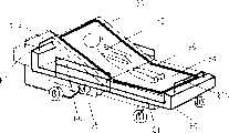
图13是根据本发明第二实施例的电动床的外部透视图。Fig. 13 is an external perspective view of an electric bed according to a second embodiment of the present invention.
图14是其中压敏传感器设置在背部抬升床板部分以及膝部抬升床板部分的表面端部的多个部分处的装置的外部透视图。14 is an external perspective view of the device in which pressure sensitive sensors are provided at portions of the surface ends of the back lift deck portion and the knee lift deck portion.
图15是示出所述装置的侧部护栏和床之间的位置关系的示意性侧视图。Fig. 15 is a schematic side view showing the positional relationship between the side rail and the bed of the device.
图16是示出就寝者碰触压敏传感器的状态的示意性透视图。Fig. 16 is a schematic perspective view showing a state where a sleeper touches the pressure-sensitive sensor.
图17是所述装置的压敏传感器的外部视图。Figure 17 is an external view of the pressure sensitive sensor of the device.
图18是一主要部分的示意图,其示出了所述装置的压敏传感器通过缝装机被固定到背部抬升床板部分和膝部抬升床板部分的状态。18 is a schematic diagram of a main part showing a state where the pressure-sensitive sensor of the device is fixed to the back-lifting deck portion and the knee-raising deck portion by a sewing machine.
图19是所述装置的用作压敏传感器的压电传感器的主要部分的透视图。Fig. 19 is a perspective view of a main part of a piezoelectric sensor serving as a pressure-sensitive sensor of the device.
图20是所述装置的具有判定装置的、用作压敏传感器的压电传感器的系统的外部视图。FIG. 20 is an external view of a system of piezoelectric sensors serving as pressure-sensitive sensors, of the device, having determination means.
图21是示出当负荷施加于所述装置的压敏传感器时的变形状态的外部视图。Fig. 21 is an external view showing a deformed state when a load is applied to the pressure-sensitive sensor of the device.
图22是一特性示图,示出了负荷施加于所述装置的压敏传感器时的负荷W、压敏传感器的位移L、压电传感器的输出信号D以及判定装置的判定输出J。22 is a characteristic diagram showing load W, displacement L of the pressure sensitive sensor, output signal D of the piezoelectric sensor, and judgment output J of the judging means when a load is applied to the pressure sensitive sensor of the device.
图23是示出所述装置的判定装置的判定程序的流程图。Fig. 23 is a flowchart showing a determination program of the determination means of the apparatus.
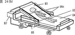
图24(a)是一外部透视图,示出了所述装置的压敏传感器以U形方式设置在背部抬升床板部分的表面上,位于上端部分和背部抬升床板部分的宽度方向上的两个端部处的情况;图24(b)是一外部透视图,示出了装置的压敏传感器设置在背部抬升床板部分的表面上,位于背部抬升床板部分的宽度方向上的两个端部处的情况。Fig. 24 (a) is an external perspective view showing that the pressure-sensitive sensor of the device is arranged on the surface of the back raised deck part in a U-shaped manner, two positions in the width direction of the upper end part and the back raised deck part. Situation at the ends; Figure 24(b) is an external perspective view showing that the pressure-sensitive sensors of the device are arranged on the surface of the back-lifting bed board part, at both ends in the width direction of the back-raising bed board part Case.
图25(a)是示出在所述装置中使用普通聚氨酯泡沫情况下的垫层状态的截面图,图25(b)是示出在所述装置中使用低推斥力(low-repulsion)聚氨酯泡沫情况下的垫层状态的截面图。Fig. 25(a) is a cross-sectional view showing the state of the cushion in the case of using ordinary polyurethane foam in the device, and Fig. 25(b) is a cross-sectional view showing the use of low-repulsion polyurethane in the device Sectional view of the cushion state in the case of foam.
图26(a)是被设置成所述装置的压敏传感器中压电传感器和非线性挠性件之间间隔的结构的截面图;图26(b)是被设置成所述装置的压敏传感器部分中具有中空部分的结构的截面图;图26(c)是设置成在所述装置的压敏传感器中设置一片状压电传感器的结构的截面图。Figure 26 (a) is a cross-sectional view of the structure of the interval between the piezoelectric sensor and the nonlinear flexible member configured as the pressure sensitive sensor of the device; Figure 26 (b) is configured as the pressure sensitive sensor of the device A cross-sectional view of a structure having a hollow portion in the sensor portion; FIG. 26(c) is a cross-sectional view of a structure configured to provide a sheet-shaped piezoelectric sensor in the pressure-sensitive sensor of the device.
图27(a)是其中压敏传感器设置在膝部抬升床板部分和背部抬升床板部分的后表面上的结构的外部透视图;图27(b)是其中压敏传感器设置在膝部抬升床板部分和背部抬升床板部分的侧表面上的结构的外部透视图;图27(c)是其中压敏传感器以之字形方式设置在床垫(mattress)的侧表面上的结构的外部透视图。FIG. 27( a ) is an external perspective view of a structure in which pressure-sensitive sensors are provided on the rear surfaces of the knee lift deck portion and the back lift deck portion; and the external perspective view of the structure on the side surface of the back lifting bed board part; FIG.
图28是根据本发明第三实施例的床的分解透视图。Fig. 28 is an exploded perspective view of a bed according to a third embodiment of the present invention.
图29(a)示出缆状压电传感器设置在不平板(uneven plate)上的情况,图29(b)示出缆状压电传感器设置在平板上的情况。Fig. 29 (a) shows the situation that the cable-shaped piezoelectric sensor is arranged on an uneven plate (uneven plate), and Fig. 29 (b) shows the situation that the cable-shaped piezoelectric sensor is arranged on a flat plate.
图30是缆状压电传感器的结构示图。Fig. 30 is a structural diagram of a cable-shaped piezoelectric sensor.
图31是示出施加到缆状压电传感器上的负荷和缆状压电传感器的传感器输出特性的示图。FIG. 31 is a graph showing a load applied to a cable-shaped piezoelectric sensor and sensor output characteristics of the cable-shaped piezoelectric sensor.
图32(a)示出用于检测心跳和呼吸的检测单元的框图,图32(b)示出用于说明将来自缆状压电传感器的响应于心跳、呼吸或由于翻身等引起的身体移动而产生的检测信号转换成脉冲信号的原理的示图。Fig. 32(a) shows a block diagram of a detection unit for detecting heartbeat and respiration, and Fig. 32(b) shows a block diagram for explaining the detection of signals from cable-shaped piezoelectric sensors in response to heartbeat, respiration, or body movement caused by turning over, etc. A schematic diagram of the principle of converting the generated detection signal into a pulse signal.
图33是示出传统电动床的外部透视图。Fig. 33 is an external perspective view showing a conventional electric bed.
图34是示出传统片的结构示图。Fig. 34 is a diagram showing the structure of a conventional sheet.
图35(a)至35(c)示出在床上使用压电传感器的各种实验示例。35(a) to 35(c) show various experimental examples using piezoelectric sensors on a bed.
附图中,标号11表示突伸片,13、55、61各自表示压敏片,15a表示寝具表面,17、53各自表示突伸片,21表示压敏传感器(第一压敏传感器),22表示压敏传感器(第二压敏传感器),23表示中心电极、25表示压电元件材料,27表示外电极,29表示护层(sheath),31表示第一信号处理单元,33表示第二信号处理单元,35表示放大电路,37表示滤波器,39表示平滑电路,41表示判定装置,43表示通知装置,51、52各自表示片,50表示床,A、B各自表示输出,H表示就寝者,80表示电动床,82表示就寝者,83表示背部抬升床板部分,84表示膝部抬升床板部分,85表示升降驱动单元,86、86a、92、93、94、110、112、114各自表示压敏传感器,87表示判定装置,88表示侧部护栏,89表示变形装置,90表示非线性挠性件,91表示压电传感器(线缆形),97表示凸缘部分,98表示中心电极,99表示外电极,100表示复合压电层,101表示覆盖层,102表示压电传感器端部,103表示断线检测电阻,104表示线缆,105表示连接器,107表示床垫的侧表面,108表示低推斥力聚氨酯泡沫,109表示普通聚氨酯泡沫,111表示中空部分,113表示压电传感器(片状),120表示床垫,121表示低推斥力聚氨酯层,122表示普通聚氨酯层,123表示缆状压电传感器布设片,124表示织物片,125表示床,126表示缆状压电传感器,127表示不平塑性板,128表示塑性板,129表示凹入部分,130表示外罩(cover bag),131表示片,132表示紧固件,134表示床架,135画框形状的框架,136表示活动板,137表示支撑板,138表示电机,145表示心跳和呼吸等的检测单元,146表示缆状压敏传感器(缆状压电传感器),147表示滤波电路,148表示放大电路,149表示计数电路,150表示显示单元。In the drawings, reference numeral 11 denotes a protruding piece, 13, 55, 61 each denote a pressure-sensitive piece, 15a denotes a bedding surface, 17, 53 each denote a protruding piece, 21 denotes a pressure-sensitive sensor (first pressure-sensitive sensor), 22 Indicates the pressure-sensitive sensor (second pressure-sensitive sensor), 23 indicates the center electrode, 25 indicates the piezoelectric element material, 27 indicates the outer electrode, 29 indicates the sheath, 31 indicates the first signal processing unit, and 33 indicates the second signal Processing unit, 35 denotes an amplifying circuit, 37 denotes a filter, 39 denotes a smoothing circuit, 41 denotes a judging device, 43 denotes a notification device, 51, 52 respectively denote chips, 50 denotes a bed, A, B respectively denote an output, H denotes a sleeper , 80 represents the electric bed, 82 represents the sleeper, 83 represents the back lifting bed board part, 84 represents the knee lifting bed board part, 85 represents the lifting drive unit, 86, 86a, 92, 93, 94, 110, 112, 114 represent the pressure Sensitive sensor, 87 means judging device, 88 means side guardrail, 89 means deformation device, 90 means nonlinear flexible part, 91 means piezoelectric sensor (cable shape), 97 means flange part, 98 means center electrode, 99 100 represents the composite piezoelectric layer, 101 represents the covering layer, 102 represents the end of the piezoelectric sensor, 103 represents the disconnection detection resistor, 104 represents the cable, 105 represents the connector, 107 represents the side surface of the mattress, 108 Indicates low repulsion polyurethane foam, 109 indicates ordinary polyurethane foam, 111 indicates hollow part, 113 indicates piezoelectric sensor (sheet), 120 indicates mattress, 121 indicates low repulsion polyurethane layer, 122 indicates ordinary polyurethane layer, 123 indicates cable 124 represents a fabric sheet, 125 represents a bed, 126 represents a cable-shaped piezoelectric sensor, 127 represents an uneven plastic plate, 128 represents a plastic plate, 129 represents a concave portion, 130 represents a cover bag, 131 132 represents a fastener, 134 represents a bed frame, 135 represents a frame in the shape of a picture frame, 136 represents a movable plate, 137 represents a support plate, 138 represents a motor, 145 represents a detection unit for heartbeat and respiration, etc., 146 represents a cable-like pressure Sensitive sensor (cable piezoelectric sensor), 147 represents a filter circuit, 148 represents an amplification circuit, 149 represents a counting circuit, and 150 represents a display unit.
具体实施方式Detailed ways
以下将参照附图说明根据本发明的床和在床状态检测方法的优选实施例。Preferred embodiments of the bed and bed occupancy detection method according to the present invention will be described below with reference to the accompanying drawings.
实施例1Example 1
图1是根据实施例1的床的分解透视图,图2是构成该装置的检测装置的压敏片的平面图,图3是示出压敏传感器和突伸片的突伸段的平面图,图4是从图3中的方向P观察到的截面图,图5是设置在压敏片上的压敏传感器的分解透视图。1 is an exploded perspective view of a bed according to
如图1所示,床50构造成使得突伸片11、压敏片13和床垫15依次层叠在框架10的床板表面10a上并组装。As shown in FIG. 1 , the bed 50 is configured such that the protruding
在突伸片11中,多个突伸段17彼此平行地沿着床50的纵向形成在突伸片的上表面侧。突伸段17不限于各自由图中所示线性连续的线形成的多个线的结构,而可以是断续设置的线形的突起、弯曲形状的突起或离散设置的突起。以压敏传感器设置在压敏片的下侧上的方式,将构成检测装置的压敏片13层叠在突伸片11的上表面上。层叠在压敏片13的上表面上的床垫15的上表面用作寝具表面15a。In the protruding
如图2所示,压敏片13具有在平面视图中呈矩形的片19以及一对压敏传感器21、22,该片19例如由柔软的无纺布(non-woven cloth)形成,所述一对压敏传感器21、22分别粘接层叠在片19的两个端侧,使得在它们之间具有一间隔,从而这些传感器被缝在片19上。As shown in FIG. 2, the pressure-sensitive sheet 13 has a rectangular sheet 19 in plan view and a pair of pressure-
压敏传感器21、22各自为使用了压电元件材料的长线缆形状的压电传感器,它们具有沿片19的两个端侧的边缘部分线性设置的直线部分21a、22a和沿所述直线部分以波浪形方式设置的波浪形部分21b、22b,该波浪形部分分别设置在片19上所述直线部分21a、22a的内侧。在这些压敏传感器21、22中,如图3所示,在平面视图中,波浪形部分21b、22b与位于波浪形部分下面的突伸片11的突伸段17相交。The pressure-
这样,如图4所示,由于躺在床垫15的寝具表面15a上的就寝者身体的重量和偏移,设置有压敏传感器21、22的压敏片13经由床垫15被推压,使得压敏传感器21、22的波浪形部分21b、22b的部分抵靠在突伸片11的突伸段17上。由此,来自就寝者的负荷局部地施加在与突伸段17相交的压敏传感器21、22上。这样,即使压敏传感器21、22的变形量增加,并且由此不仅在波浪形的波幅方向(床的宽度方向),而且在与之正交的方向(床的纵向)上均显现出就寝者的变形时,也可以确保检测到变形。Like this, as shown in FIG. Parts of the wave-shaped
接下来将说明压敏传感器21、22的具体构造。Next, specific configurations of the pressure-
如图5所示,压敏传感器21、22中的每一个布置成在沿其轴向的中心部分处具有一线圈形状的中心电极23,压电元件材料25覆盖在中心电极23的周围,外电极27设置在压电元件材料的外围,并且传感器的最外围覆盖有由氯乙烯树脂等制成的护层29。As shown in FIG. 5, each of the pressure-
在每个压敏传感器21、22中,具有能够承受120℃的可用温度的耐热性的树脂材料被用作压电元件材料25。压电元件材料具有能够用在高于90℃温度范围(120℃或更低)的特性,该温度范围是传统典型高分子压电元件材料(单轴取向的聚偏二氟乙烯)或由氯丁二烯和压电陶瓷粉末制成的压电元件材料的最大可用温度。In each of the pressure
此外,压电元件材料25由具有挠性的树脂和压电陶瓷形成,中心电极23由线圈形状的金属形成,膜状的挠性电极被用作外电极27,从而传感器具有类似于普通聚乙烯绳的挠性。In addition, the
此外,每个压敏传感器21、22具有类似于高分子压电元件材料的高灵敏度,并在低频范围(10Hz或更低)用于检测人体移动时具有类似于高分子压电元件材料的高灵敏度。这是因为压电元件材料25的介电常数(约为55)大于高分子压电元件材料的介电常数(约为10),从而即使在低频范围(10Hz或更低)其灵敏度的降低程度也较低。In addition, each of the pressure-
压电元件材料25由树脂材料和10μm或更小的压电陶瓷粉末通过复合构成。压电元件材料的振动检测特性和挠性是通过陶瓷和树脂分别实现的。The
在压电元件材料25中,由于聚氯乙烯被用作树脂材料,实现了有利于形成以及高耐热性(120℃)的挠性,并且可以实现不需要桥接(bridging)处理的更为简单的制造工艺。In the
由此获得的每个压敏传感器21、22在仅仅形成压电元件材料25的情况下不具有压电效应。因此,必须进行处理(极化处理),即通过向压电元件材料25施加几kV/mm的DC高压使压电元件材料25产生压电效应。该极化处理的执行方式为在压电元件材料25形成外电极27和中心电极23之后,在两个电极23、27上施加DC高压。Each of the pressure-
当在压电元件材料25中存在例如裂纹之类的小缺陷时,有可能在缺陷部分发生放电,因此在两个电极之间可能发生短路,从而不能施加足够的极化电压。但是,在压敏传感器21、22中,由于进行了独特的极化处理,即其中使用了能够粘附到恒定长度的压电元件材料25的一辅助电极,所以可以检测并避免缺陷,从而稳定极化,从而传感器可以加长而具有10m或更长的长度。When there is a small defect such as a crack in the
此外,在每个压敏传感器21、22中,由于线圈形状的金属中心电极被用作中心电极,而膜状电极(铝、聚对苯二甲酸乙二醇酯和铝的三层层叠的膜)被用作外电极27,确保了压电元件材料25和相应电极23、27之间的粘附。此外,可以方便地耦接外部引线,并且可以实现挠性线缆形状的安装结构。Furthermore, in each of the pressure-
铜-银合金线圈被用作中心电极23,铝、聚对苯二甲酸乙二醇酯和铝的三层层叠的膜被用作外电极27,聚乙烯树脂加压电陶瓷粉末被用作压电元件材料25和热塑性塑料,从而介电常数为55,电荷生成量为10至13C(库仑)/gf,并且最大可用温度为120℃。A copper-silver alloy coil was used as the
每个压敏传感器21、22布置成仅在向其施加力的时候输出信号,而即使该力继续施加于其上,只要没有偏移就不再输出任何信号。类似地,每个传感器具有检测加速度的特性,使得仅在移除力的时候才输出信号。这样,在每个压敏传感器21、22中,即使它是以弯曲方式设置的,该传感器在它被弯曲的时候输出信号,而在移位完成之后不输出信号。据此,每个压敏传感器21、22仅在向其一部分施加力的时候输出信号。Each pressure
因此,即使在缆状压电传感器以波浪形方式设置在床的下部的情况下,传感器在它们被弯曲的时候处于工作状态,而在移位完成之后不输出信号。据此,每个缆状压电传感器仅在向其一部分施加力的时候输出信号。Therefore, even in the case where the cable-like piezoelectric sensors are arranged in a wave-like manner at the lower portion of the bed, the sensors are in an active state when they are bent, and do not output a signal after the displacement is completed. Accordingly, each cable-like piezoelectric sensor outputs a signal only when force is applied to a portion thereof.
接下来将更为详细地说明床的结构和功能。Next, the structure and function of the bed will be described in more detail.
图6是示出床的检测装置的结构和功能的框图。Fig. 6 is a block diagram showing the structure and function of the bed detection device.
设置在压敏片13上的一对压敏传感器21、22中的一个和另一个分别用作第一压敏传感器21和第二压敏传感器22。One and the other of a pair of pressure-
第一压敏传感器21耦接至第一信号处理单元31,第二压敏传感器22耦接至第二信号处理单元33。在信号处理单元31、33中,来自压敏传感器21、22的输出信号分别被施加到放大电路35。The first pressure
第一信号处理单元31和第二信号处理单元33中的每一个布置成滤波器37和平滑电路39设置在放大电路35之后的阶段中,而来自第一压敏传感器21和第二压敏传感器22中对应的一个的输出信号被放大电路35放大,然后由滤波器37滤波得到所需的频率分量,并且由平滑电路39对信号波形进行平滑。Each of the first
然后,第一信号处理单元31和第二信号处理单元33的每一个被耦接至判定装置41。经平滑电路39平滑的电信号输入到判定装置41中。Then, each of the first
判定装置41基于来自第一信号处理单元31和第二信号处理单元33的电信号,判定躺在床垫15的寝具表面15a上的就寝者的位置的偏移。The determination means 41 determines a shift in the position of the sleeper lying on the
此外,一通知装置43耦接至判定装置41,通知装置43由例如扬声器的声音输出装置或例如显示器的显示装置构成。判定装置41根据就寝者的位置偏移的判定结果向通知装置43输出通知信号。然后,通知装置43响应于从判定装置41接收到的通知信号,通过声音或显示或两者组合的方式输出警报,从而通知就寝者在寝具表面15a上的位置偏移了。Furthermore, a
顺便提一下,第一压敏传感器21和第二压敏传感器22中的每一个经由一电阻性电路45耦接至电源47,并预先从电源47经由电阻性电路45向其供以用于检测的驱动电压。Incidentally, each of the first pressure-
判定装置41根据来自第一信号处理单元31和第二信号处理单元33的电信号的强度(利用信号的幅值或峰值的积分强度等)之间的比率判定就寝者的位置偏移。具体而言,如图7所示,预先制定一表,该表判定出与来自第一信号处理单元31和第二信号处理单元33的电信号的输出A、B的强度的比率对应的偏移范围。然后,比较来自第一信号处理单元31和第二信号处理单元33的电信号的输出A、B,并判定输出A、B的强度比率是处于预定的偏移状态的范围内,还是处于非偏移状态的范围内。The judging means 41 judges the positional shift of the sleeper based on the ratio between the intensities of the electric signals from the first
这样,当输出A、B的强度比率在远离非偏移状态的偏移状态范围时,判定装置41判定就寝者在寝具表面15a上的位置偏移了,从而向通知装置43输出通知信号。In this way, when the intensity ratio of the outputs A and B is within the range of the offset state away from the non-offset state, the determining
通知装置43响应于该通知信号通过声音或显示或两者组合的方式向例如看护人员的第三方输出警报,从而通知就寝者在寝具表面15a上的位置偏移了。The
在设置有由以上述方式构造的用于就寝者的检测装置的床中,在检测偏移之前进行调节,以便校正就寝者之间的个人差异,从而可以大大地提高检测准确性。具体的调节处理如下,首先,如图8(a)所示,在就寝者H躺在第一压敏传感器21和第二压敏传感器22之间的状态下,旋转设置在判定装置41处的一未示出的调节柄,从而进行调节,使得来自第一信号处理单元31的输出A的强度与来自第二信号处理单元33的输出B的强度大致一致。In a bed provided with the detection device for a sleeper constructed in the above manner, adjustment is made before detection of deviation so as to correct individual differences among sleepers, so that detection accuracy can be greatly improved. The specific adjustment process is as follows. First, as shown in FIG. An adjustment handle not shown, so that the intensity of the output A from the first
在此调节之后的状态下,如图8(b)或(c)所示,当寝具表面15a上的就寝者H在寝具表面15a上偏移时,施加到第一压敏传感器21和第二压敏传感器22上的负荷变化。根据负荷的变化,突伸片11的突伸段对压敏传感器的推压力也很大地变化,从而第一压敏传感器21和第二压敏传感器22输出检测信号。在图8(b)所示情况下,就寝者H的头部位于第一压敏传感器21上,而就寝者的脚部位于第二压敏传感器22上。由于头部比脚部沉,所以头部在床垫15中下陷得更低,因此头部处的压敏传感器的输出比脚部处的压敏传感器的输出大。因而,输出A、B的信号强度之间的差值变大。这样,就可以检测就寝者的偏移状态。通过这种方式,由于在就寝者H处于偏移状态时负荷变化大,所以可以检测出偏移状态。此外,即使在就寝者已经以偏移状态发生了偏移并现处于静止状态时,压敏传感器21、22也可以检测到由于由呼吸或心跳所引起的身体的较小偏移造成的振动。因此,通过比较振动的幅度,可以判定就寝者是否处于偏移状态。In the state after this adjustment, as shown in FIG. 8(b) or (c), when the sleeper H on the
此外,具体而言,在图8(c)所示的就寝者很可能跌落的偏移状态下,压敏传感器21、22的输出信号的强度之间的差异变得特别大。在根据输出信号的强度差异的大小对通知级别进行分类的情况下,可以以一种区分出需要紧急措施的情况的方式进行通知。Moreover, specifically, in the offset state shown in FIG. 8( c ) in which the sleeping person is likely to fall, the difference between the intensities of the output signals of the pressure-
此外,在这种情况下,就寝者H的重量造成的床垫15的下陷所引起的拉伸力作用在第一和第二压敏传感器21、22的直线部分21a、22a上,由此也产生了检测信号。这样,进一步提高了检测灵敏度。In addition, in this case, the stretching force caused by the sag of the mattress 15 due to the weight of the sleeping person H acts on the
由此,根据上述用于就寝者的检测装置和检测方法,各自由线缆形状的压电传感器构成的第一压敏传感器21和第二压敏传感器22分别沿寝具表面15的侧边缘设置在寝具表面15a的两个端侧,并且判定装置41比较来自第一压敏传感器21和第二压敏传感器22的输出信号,以判定寝具表面15a上就寝者向侧部的位置偏移。从而,可以从判定结果中得到就寝者的就寝状态,由此,可以预先防止就寝者从寝具表面15a跌落等情况。Thus, according to the detection device and detection method for sleepers described above, the first pressure-
此外,由于线缆形状的压电传感器仅设置在寝具表面15a的两个端侧,与沿着床的宽度方向和纵向以其间具有一间隔的格栅方式设置很多个由昂贵的压电元件构成的传感器的情况相比,最大可能地防止成本的增加。In addition, since the cable-shaped piezoelectric sensors are provided only on both end sides of the
此外,由于每个压敏传感器21、22本身是具有相当高灵敏度的传感器,所以即使在设置有压敏传感器21、22的压敏片13设置在床垫15下面时,也能够获得足够的检测灵敏度,使得可以消除压敏传感器严重影响床的舒适性的问题。此外,即使在压敏传感器21、22就设置在寝具表面15a之下的情况下,由于压敏传感器21、22没有设置在寝具表面15a的中心部分,而且压敏传感器21、22自身具有挠性,所以可以最大可能地防止影响床的舒适性。In addition, since each of the pressure-
此外,仅仅通过层叠设有压敏传感器21、22的压敏片13和设有突伸段17的突伸片11,就可以相当容易地提高压敏传感器21、22的检测灵敏度。Furthermore, the detection sensitivity of the pressure-
顺便提一下,在上述实施例中,尽管通过将设有突伸段17的突伸片11层叠在设有压敏传感器21、22的压敏片13上,灵敏度可得以提高,但是可以以上述方式来构造用于提高灵敏度的结构。Incidentally, in the above-mentioned embodiment, although the sensitivity can be improved by laminating the protruding
图9所示构造布置成对于各自由例如无纺布等形成的两个片51、52,压敏传感器21、22被粘附到一个片51上,各由线材(wire rod)等形成的突伸段53形成在另一个片52上,并且这些片51、52被层叠,以构成压敏片55。在使用压敏片55的情况下,可以不使用上述突伸片11,从而可以简化结构。此外,根据该构造,突伸段53起到将来自就寝者的负荷作为较大的力局部地施加在压敏传感器21、22上,从而可以提高灵敏度。当然,突伸段53可以设置在压敏传感器21、22的上面或下面。The configuration shown in FIG. 9 is arranged so that, for two
可以通过压敏传感器21、22检测到就寝者的心跳,并且可以基于检测的结果管理就寝者的健康状态。The heartbeat of the sleeper can be detected by the pressure-
接下来将说明根据第一实施例的压敏片的一变型示例。Next, a modified example of the pressure-sensitive sheet according to the first embodiment will be described.
图10是示出第一实施例的压敏片的变型示例的示意平面图。Fig. 10 is a schematic plan view showing a modified example of the pressure-sensitive sheet of the first embodiment.
将一压敏片61布置成每个压敏传感器21、22的波浪形部分的相邻波形间隔更短,从而增大躺在寝具表面15a上的就寝者的头部侧的区域Wa中的布线密度。相反,使每个压敏传感器21、22的波浪形部分的相邻波形间隔更长,从而减小躺在寝具表面15a上的就寝者的腿部侧的区域Wc中的布线密度(图中示出使压敏传感器在就寝方向上成线性从而使布线密度最小的一个示例)。A pressure-
通常,如图11所示,当就寝者躺下时,在头部、背部和臀部处,大的负荷施加在寝具表面15a上,而在腿部处并没有施加大的负荷。具体而言,就寝者的位置偏移受到头部的位置偏移的很大影响。因此,在该实施例中,将压敏传感器21、22布置成在头部侧布线密度高,以便检测即使是较小的偏移,而在偏移相对频繁因而易于造成错误检测的腿部侧,使其布线密度低。Generally, as shown in FIG. 11, when a sleeper lies down, a large load is applied to the
在根据该实施例的用于就寝者的检测装置中,如图12(a)所示,即使当使得就寝者H以歪斜方式躺在寝具表面15a上,从而略微地躺在区域Wa中的压敏传感器21上面而发生偏移时,也可以确保以高灵敏度检测到就寝者H的头部的位置偏移。In the detecting device for a sleeping person according to this embodiment, as shown in FIG. Even when the position of the head of the sleeping person H deviates from above the
此外,由于如图12(b)所示,将压敏传感器21、22布置成其密度在腿部侧较低,所以即使在没有显现出偏移状态,就寝者H躺在寝具表面15a的中心部分同时其腿张开的情况下,也可以消除由于就寝者H位置偏移而发出不必要警报的问题。Furthermore, since the pressure-
此外,如图12(c)所示,当就寝者H体重较轻并且象小孩等一样小时,压敏传感器21、22的检测灵敏度变低。但是由于腿部侧的压敏传感器21、22设置成更加靠近中心部分,所以可以确保执行对就寝者H的检测。这样,可以确保检测到就寝者的存在,并进一步如上述情况中一样以高准确度检测到就寝者的位置偏移。Furthermore, as shown in FIG. 12(c), when the sleeping person H is light in weight and small like a child or the like, the detection sensitivity of the pressure-
各个实施例中的压敏传感器21、22希望是由上述材料制成的压电传感器。但是,在本发明中,压敏传感器不限于这样的传感器,而可以使用诸如电接触类型的线缆形状的传感器之类的各种压敏传感器,其布置成例如一对电触点埋设在线缆中,并且触点由于线缆的弯曲而彼此接触,从而检测压力。The pressure-
实施例2Example 2
以下将参照图13-27说明本发明的第二实施例。A second embodiment of the present invention will be described below with reference to FIGS. 13-27.
本发明的第二实施例是基于图13-27来进行说明的。图13是安装了压敏传感器的电动床的外部透视图。图14是其中压敏传感器设置在膝部抬升床板部分和背部抬升床板部分的表面端部的多个部分处的装置的外部透视图。图15是示出所述装置的床和侧部护栏之间位置关系的示意性侧视图。图16是示出就寝者碰触压敏传感器的状态的示意性透视图。The second embodiment of the present invention is described based on FIGS. 13-27. Fig. 13 is an external perspective view of the electric bed installed with the pressure sensitive sensor. 14 is an external perspective view of the device in which pressure sensitive sensors are provided at portions of the surface ends of the knee lift deck portion and the back lift deck portion. Fig. 15 is a schematic side view showing the positional relationship between the bed and the side rails of the device. Fig. 16 is a schematic perspective view showing a state where a sleeper touches the pressure-sensitive sensor.
如图13所示,作为根据第二实施例的床的电动床80布置成:作为与就寝者82的上部对应的部分的床板部分的背部抬升床板部分83和作为对应于就寝者下部的部分的膝部抬升床板部分84安装在床架81上。床架81包括设置在背部抬升床板部分83的上端侧的抬升架81a和设置在膝部抬升床板部分84的下端侧的抬升架81b。此外,该装置包括用于抬升就寝者82的上部和下部的驱动装置85。压敏传感器86根据就寝者82碰触传感器时施加的压靠负荷所引起的压敏传感器的变形产生输出信号。为此,压敏传感器沿背部抬升床板部分83和膝部抬升床板部分84的表面端部的整个外围设置,并且还沿着背部抬升床板部分83和膝部抬升床板部分84的侧边缘设置。设置一判定装置87,其基于根据压敏传感器86变形获得的输出信号判定就寝者是否碰触压敏传感器86。驱动装置85的升降驱动操作由控制装置(未示出)根据来自判定装置87的判定信号来控制。在电动床80沿着床架81的宽度方向的两侧上设置有侧部护栏88。As shown in FIG. 13 , an
如图14所示,压敏传感器可以构造成设置在背部抬升床板部分和膝部抬升床板部分的表面端部的部分处。由于与将传感器设置在整个外围的结构相比,压敏传感器的长度可以更短,所以该构造更为实用。As shown in FIG. 14 , the pressure-sensitive sensors may be configured to be provided at portions of surface ends of the back lift deck portion and the knee lift deck portion. This configuration is more practical because the length of the pressure-sensitive sensor can be shortened compared to a structure in which the sensor is provided on the entire periphery.
图15示出电动床中床与侧部护栏之间的位置关系。侧部护栏88和床架81或者作为床的背部抬升床板部分83和膝部抬升床板部分84的侧表面107之间,需要一个较小的间隙来附接侧部护栏88。这样,在升降背部抬升床板部分83的时候,可能会发生物件不小心被卡在该间隙中。尽管侧部护栏88是设置为了防止就寝者2从床上跌落的,但是在与电动床结合时需要进行安全控制。Fig. 15 shows the positional relationship between the bed and the side rails in the electric bed. Between the side rails 88 and the
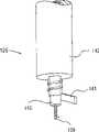
图17是压敏传感器的外部视图。图18是示出了压敏传感器通过缝装机被固定到背部抬升床板部分和膝部抬升床板部分的状态的主要部分的示意图。图19是用作压敏传感器的压电传感器的主要部分的透视图。图20是具有判定装置的用作压敏传感器的压电传感器的系统的外部视图。Fig. 17 is an external view of the pressure sensitive sensor. Fig. 18 is a schematic diagram of a main part showing a state in which the pressure-sensitive sensor is fixed to the back-lifting deck portion and the knee-raising deck portion by a sewing machine. Fig. 19 is a perspective view of a main part of a piezoelectric sensor used as a pressure sensitive sensor. Fig. 20 is an external view of a system of a piezoelectric sensor used as a pressure-sensitive sensor with a determination device.
在图17中,压敏传感器86(包括86a,但是以下仅称为86)设置有由弹性部件形成的变形装置89、非线性挠性部件和挠性线缆形状的压电传感器91。作为非线性挠性部件90,采用了例如以外凸方式使用的带状薄型的凸形弹性部件。这样的带状薄型弹性部件具有以下特性,即,在施加于其上的压力负荷达到预定值或者更大时它突然以内凹形状变形,并且在压力负荷移除时回复到原始形状。In FIG. 17, a pressure sensitive sensor 86 (including 86a, but hereinafter simply referred to as 86) is provided with a
图18所示的传感器布置成利用缝装机通过缝合线96将压敏传感器86的附接凸缘部分97牢固地结合在背部抬升床板部分83和膝部抬升床板部分84的表面端部处。压敏传感器86可以构造成通过双面粘贴带或者粘接剂等被牢固地结合在背部抬升床板部分83和膝部抬升床板部分84上。The sensor arrangement shown in FIG. 18 is such that the attachment flange portion 97 of the pressure
图19是示出根据本发明第一实施例的挠性线缆形状的压电传感器91的一部分的主要部分的结构的示图。FIG. 19 is a diagram showing the structure of a main part of a part of the flexible cable-shaped
压电传感器91构造成同心地层叠用作用于提取信号的电极的中心电极98、外电极99、由通过将烧结的压电陶瓷粉末混合到橡胶弹性材料中形成的复合电材料制成的复合压电层100、以及覆盖层101,然后将其形成为线缆形状并经过极化处理。该压电传感器具有如图5所示的类似构造和非常好的挠性,并根据其弹性变形产生输出信号。作为压电陶瓷,使用例如钛酸铅、钛锆酸铅(titanate lead zirconate)之类的铅基压电材料的烧结粉末,或者使用例如铌酸钠之类的非铅基的压电材料的烧结粉末。作为中心电极98,尽管可以使用普通金属单线,但是这里使用了通过将金属绕线缠绕在绝缘高分子(macromolecular)纤维的外周上而形成的电极。作为绝缘高分子纤维和金属绕线,希望分别采用商业上用于电热毯的聚合物纤维和含重量百分比5%的银的铜合金。此外,作为外电极99,使用通过在高分子层上粘附金属膜形成的带状电极。外电极构造成使得这样形成的带状电极缠绕在复合压电层100的外周上。使用聚对苯二甲酸乙二醇脂(PET)作为高分子层.通过在高分子层上粘附铝膜形成的带状电极具有耐120℃的耐热性,并且可商业上大量生产,使得优选以带状电极作为外电极99。The
顺便提一下,为了遮蔽来自外部环境的电噪声,用作压敏传感器86的压电传感器22优选布置成外电极99缠绕在复合压电层100的外周,以便部分地重叠于其上。尽管氯乙烯和聚乙烯可以用作覆盖层101,但是也可以使用诸如橡胶之类的比复合压电层100具有更好的挠性和弹性的弹性材料,由此压电传感器91可在就寝者82碰触传感器时弹性变形。作为这样的橡胶,可以使用例如乙烯丙烯橡胶(EPDM)、氯丁二烯橡胶(CR)、丁基橡胶(IIR)、硅橡胶(Si)或者热塑性的弹性体。Incidentally, in order to shield electrical noise from the external environment, the
图20是具有判定装置87的用作压敏传感器86的压电传感器91的系统的外部视图。在图20中,在线缆形状的压电传感器91的一个端部102中包括断线检测电阻103。断线检测电阻103耦接在线缆形状的压电传感器91的中心电极98和外部电极99之间。断线检测电阻103还用作放电部分,用于释放压电传感器91由于热电效应产生的电荷,从而部件可以正常化。用于判定就寝者82对传感器的碰触的判定装置87直接耦接至压电传感器91,从而压电传感器91和判定装置87结合在一起。104表示用于供电和输出检测信号的线缆,105表示连接器。FIG. 20 is an external view of a system of a
接下来将说明上述构造的操作和功能。Next, the operation and function of the above-described configuration will be explained.
如图16所示,在就寝者82在背部抬升床板部分83和膝部抬升床板部分84的升降操作过程中由于一些原因变换姿势,从仰卧状态变为侧卧状态,从而从背部抬升床板部分83和膝部抬升床板部分84的大致中间的位置偏移到端部位置的情况下,如果就寝者82碰触压敏传感器86,则来自压敏传感器86的输出信号被发送至判定装置87,从而判定装置87判定就寝者82碰触了传感器。然后驱动装置受到控制装置(未示出)的控制,立即停止对背部抬升床板部分83和膝部抬升床板部分84的升降驱动。在这种情况下,可以控制背部抬升床板部分83和膝部抬升床板部分84,使其回复到它们起始的位置。这种情况下,如果就寝者身体在停止驱动操作时被卡住,则由于该卡住状态可以被松开,所以装置的安全性可以进一步提高。As shown in FIG. 16, during the lifting operation of the back-lifting
上述操作控制仅在背部抬升床板部分83和膝部抬升床板部分84处于升降驱动过程中的时候进行,而在背部抬升床板部分83和膝部抬升床板部分84的非驱动状态过程中并不进行,即使压敏传感器86检测到就寝者82的偏移。The above-mentioned operation control is only performed when the back lifting
此外,在就寝者82的一部分身体在背部抬升床板部分83的升降操作过程中由于一些原因从背部抬升床板部分83的上端伸出的情况下,如果身体的该部分碰触压敏传感器86,则来自压敏传感器86的输出信号被发送至判定装置87,从而判定装置87判定就寝者82碰触传感器。随后,对背部抬升床板部分83和膝部抬升床板部分84的升降驱动立即被停止。这样,可以防止身体的一部分不小心抵靠在抬升架81a上以及身体的一部分不小心被抬升架81a卡住的问题。Furthermore, in the case where a part of the body of the
此外,在就寝者82的一部分身体在膝部抬升床板部分84的升降操作过程中由于一些原因从膝部抬升床板部分84的下端伸出的情况下,如果身体的该部分碰触压敏传感器86,则来自压敏传感器86的输出信号被发送至判定装置87,从而判定装置87判定就寝者82碰触传感器。随后,对膝部抬升床板部分84的升降驱动立即被停止。这样,可以防止身体的一部分不小心抵靠在抬升架81b上以及身体的一部分不小心被抬升架81b卡住的问题。Furthermore, in the case where a part of the body of the
图21是在由于就寝者82碰触传感器而在压敏传感器86上施加了负荷W时压敏传感器86的变形状态的外部视图。图22是示出负荷W、压敏传感器86的位移L(见图21)、压电传感器91的输出信号D以及判定装置的判定输出J的特性图。在图22中,从顶部起纵坐标表示W、L、D和J,而横坐标表示时间t。FIG. 21 is an external view of a deformed state of the pressure-
在图21和22中,当由于就寝者82碰触传感器而在压敏传感器86上施加了负荷W并且W在时间点t1变得大于W1时,非线性挠性部件90变形成内凹形状,从而L以非线性方式迅速增大。图21示出了这种情况下的这一状态。此时,由于压敏传感器91也很大地变形,所以D显现出大信号。然后,当D大于D1时,判定装置87判定就寝者82碰触传感器,从而在时间点t2将J设为高水平(Hi)并保持这一水平。然后,W逐渐减小,当W在时间点t3小于W1时,非线性挠性部件90变形成外凸形,并回复到原始形状,从而L以非线性方式迅速减小。此时,由于压电传感器91在与上述方向相反的方向上变形仍然很大,所以D显现出与以上情况中的信号极性相反的大信号。然后,当D小于D2时,判定装置87判定就寝者离开了传感器,从而在时间点t4将J设为Lo。In FIGS. 21 and 22, when a load W is applied to the pressure-
图23是示出上述判定程序的流程图。首先,当操作开始时,J被设为表示没有被就寝者82碰触的Lo,作为步骤ST1的初始值。当步骤ST2中D被判定为大于D1时,在步骤ST3中判定就寝者82碰触传感器,从而将J设为Hi。相反,如果D被判定为等于或小于D1,则一直等待直到步骤ST2中D变得大于D1。接下来,当在步骤ST4中D被判定为小于D2时,处理返回步骤ST1,并且判定就寝者12离开了传感器,从而将J设为Lo。相反,如果D被判定为等于或者大于D2,则一直等待直到在步骤ST4中D变成小于D2。FIG. 23 is a flowchart showing the above-mentioned determination procedure. First, when the operation starts, J is set to Lo indicating that it is not touched by the
将非线性挠性部件和具有挠性的压电传感器的组合作为根据实施例的压敏传感器的原因如下:The reason for combining the nonlinear flexible member and the piezoelectric sensor having flexibility as the pressure-sensitive sensor according to the embodiment is as follows:
(1)在作为检测负荷类型的压敏传感器,电极接触类型的带状压敏传感器或者阻值根据负荷而改变的压敏电阻变化类型的压敏传感器各自正常使用的情况下被设置在床的床垫的周围的情况下,当升降驱动背部抬升床板部分或膝部抬升床板部分时,由于压敏传感器在床垫弯曲的部分处弯曲而产生的应力的作用,压敏传感器会导致错误检测。(1) When the pressure sensitive sensor of the detection load type, the strip pressure sensitive sensor of the electrode contact type, or the pressure sensitive resistance change type of the pressure sensitive sensor whose resistance value changes according to the load are each normally used, it is installed on the side of the bed In the case of the surroundings of the mattress, when the lift drives the back to lift the deck part or the knees to lift the deck part, the pressure sensitive sensor may cause false detection due to the stress generated by the pressure sensitive sensor being bent at the curved part of the mattress.
(2)为了解决上述问题,当压敏传感器被分开并且将其分开部分分离设置以避免弯曲部分时,即使当物体接触压敏传感器时,由于床垫的柔软性它会吸收压力,所以显现出没有检测到接触的情况。特别是,在采用了使用用于预防褥疮的身体压力分布性能非常好的低推斥力聚氨酯泡沫的床的情况下,这样的未检测情况很可能发生。(2) In order to solve the above problems, when the pressure sensitive sensor is divided and its divided part is separated to avoid the bent part, even when an object touches the pressure sensitive sensor, it absorbs the pressure due to the softness of the mattress, so it appears No contact was detected. In particular, such non-detection is likely to occur in the case of a bed using low-repulsion polyurethane foam excellent in body pressure distribution properties for preventing decubitus ulcers.
相反,本实施例的压敏传感器使用具有挠性并根据变形的加速度来产生输出信号的传感器。考虑到安全性,背部抬升床板部分和膝部抬升床板部分的升降驱动的操作速度较低。这样,上述的床垫的弯曲部分处造成的压敏传感器的变形加速度也变得较小,使得来自压电传感器的由升降驱动产生的输出信号可以被抑制到较小的值。从而,可以通过适当地选择判定装置中用于判定接触的阈值来避免错误的判定。In contrast, the pressure-sensitive sensor of the present embodiment uses a sensor that has flexibility and generates an output signal according to the acceleration of deformation. In consideration of safety, the operation speed of the lifting drive of the back lift deck part and the knee lift deck part is low. In this way, the deformation acceleration of the pressure sensitive sensor caused at the above-mentioned curved portion of the mattress also becomes smaller, so that the output signal from the piezoelectric sensor by the lift drive can be suppressed to a small value. Thus, erroneous determination can be avoided by appropriately selecting a threshold value for determining contact in the determination means.
此外,由于还使用了非线性挠性部件,所以即使床垫是柔软的并且接触速度较低,非线性挠性部件在由于与物体的接触而被施加了预定值或者更大的负荷时也会突然变形。这样,因为压电传感器由于这样的非线性挠性部件的位移也突然变形,所以可以从压敏传感器获得具有足以用于检测与物体的接触的幅值的输出信号。In addition, since the non-linear flexible part is also used, even if the mattress is soft and the contact speed is low, the non-linear flexible part will not Suddenly deformed. In this way, since the piezoelectric sensor is also suddenly deformed due to the displacement of such a nonlinear flexible member, an output signal having an amplitude sufficient for detecting contact with an object can be obtained from the pressure sensitive sensor.
如上所述,本实施例布置成控制设置在背部抬升床板部分和膝部抬升床板部分中至少一个的表面端部的部分或整个外围上的压敏传感器、用于根据来自压敏传感器的输出信号判定就寝者对压敏传感器的接触的判定装置、以及用于根据来自判定装置的判定信号升降驱动背部抬升床板部分和膝部抬升床板部分的驱动装置。这样,当判定在背部抬升床板部分或膝部抬升床板部分的升降操作过程中就寝者接触压敏传感器时,可以进行这种控制,停止对背部抬升床板部分或膝部抬升床板部分的升降驱动,或者反转驱动方向。由此,可以防止在床的升降移动的时候不小心被卡住。As described above, the present embodiment is arranged to control the pressure-sensitive sensor provided on part or the entire periphery of the surface end of at least one of the back-lift deck portion and the knee-lift deck portion for judging means for judging the contact of the pressure sensitive sensor by the sleeper, and driving means for driving up and down the back lift deck part and the knee lift deck part according to the judgment signal from the judge means. Thus, when it is determined that a sleeper touches the pressure-sensitive sensor during lifting operation of the back-lifting deck portion or the knee-lifting deck portion, such control can be performed to stop the lifting drive of the back-lifting deck portion or the knee-raising deck portion, Or reverse the drive direction. Thus, it is possible to prevent accidental jamming when the bed is raised and lowered.
此外,由于压敏传感器由位移量相对于负荷呈非线性的非线性挠性部件和根据非线性挠性部件的位移而变形的具有挠性的压电传感器构成,所以可以提高就寝者接触压敏传感器相应的灵敏度。这是因为当就寝者在压敏传感器上的压靠负荷大于等于预定值时,非线性挠性部件突然变形。这样,由于压电传感器由于非线性挠性部件的位移也突然变形,所以可以从压敏传感器获得具有足以用于检测与物体的接触的幅值的输出信号。In addition, since the pressure-sensitive sensor is composed of a nonlinear flexible member whose displacement is nonlinear with respect to the load and a flexible piezoelectric sensor deformed according to the displacement of the nonlinear flexible member, it is possible to improve the contact pressure sensitivity of the sleeping person. The corresponding sensitivity of the sensor. This is because the non-linear flexible member is suddenly deformed when the pressure-sensitive sensor is pressed by a sleeper with a load equal to or greater than a predetermined value. In this way, since the piezoelectric sensor is also suddenly deformed due to the displacement of the nonlinear flexible member, an output signal having a sufficient amplitude for detecting contact with an object can be obtained from the pressure sensitive sensor.
此外,由于非线性挠性部件由形成为带状并具有外凸部分的薄型弹性材料构成,所以它简单且实用性高。In addition, since the nonlinear flexible member is formed of a thin elastic material formed in a belt shape and having a convex portion, it is simple and highly practical.
此外,由于非线性挠性部件和压电传感器设置在能够根据负荷发生变形的变形装置中,所以非线性挠性部件和压电传感器都更加易于在向其施加负荷时变形,从而可以进一步提高压敏传感器的灵敏度。In addition, since the nonlinear flexible member and the piezoelectric sensor are provided in a deformation device capable of deforming according to a load, both the nonlinear flexible member and the piezoelectric sensor are more easily deformed when a load is applied thereto, thereby making it possible to further increase the pressure. Sensitivity of the sensitive sensor.
此外,控制装置被设置用来在驱动装置进行升降驱动时使来自判定装置的判定信号生效,以及用来在驱动装置没有进行升降驱动时使来自判定装置的判定信号无效。因此,即使例如在背部抬升床板部分不动时就寝者或者第三方碰触压敏传感器的情况下,也能防止背部抬升床板部分不小心被驱动升降。由于使得来自判定装置的判定信号仅在背部抬升床板部分被升降驱动时有效,所以可以提供一种具有安全感且不会误操作的电动床。In addition, the control device is configured to enable the determination signal from the determination device when the drive device is driving up and down, and to invalidate the determination signal from the determination device when the drive device is not driving up and down. Therefore, even if, for example, a sleeper or a third party touches the pressure-sensitive sensor while the back-lifting deck portion is stationary, the back-lifting deck portion can be prevented from being accidentally driven up and down. Since the judgment signal from the judging device is valid only when the back-lifting bed board portion is driven up and down, it is possible to provide an electric bed that has a sense of security and is free from misoperation.
顺便提一下,就该实施例而言,尽管对于驱动升降背部抬升床板部分83和膝部抬升床板部分84的电动床进行了描述,但是与压敏传感器86、86a具有相同构造的压敏传感器可以应用于仅仅背部抬升床板83被驱动升降的电动床中。Incidentally, with this embodiment, although the description has been made for an electric bed that drives and lowers the back
将基于图24进行说明具有该构造的压敏传感器的布置。图24(a)示出压敏传感器86b沿背部抬升床板部分83的上端侧和宽度方向的两个端侧的侧边缘以U形方式设置在背部抬升床板部分的表面上。图24(b)示出压敏传感器86c沿着背部抬升床板部分83的宽度方向上的两个端部的侧边缘设置在背部抬升床板部分的表面上。设置了判定装置87,其根据来自压敏传感器86b或86c的输出信号判定就寝者与压敏传感器86b或86c的接触。这样,如果根据判定装置87的判定结果,背部抬升床板部分83被控制停止升降驱动或者回复其原始位置,则可以提供一种能够防止不小心卡住就寝者的电动床。The arrangement of the pressure-sensitive sensor having this configuration will be described based on FIG. 24 . Fig. 24(a) shows that the pressure-sensitive sensor 86b is arranged on the surface of the back raising bed board part in a U-shaped manner along the upper end side of the back raising
此外,它可以布置成将由压电传感器形成的压敏传感器设置在床垫的两侧,以便压敏传感器检测就寝者在床垫上的躺卧位置的偏移,当判定存在该偏移时,禁止升降驱动,从而预先防止被卡。这种情况下,该偏移是例如以如下方式判定的:每个压电传感器基于就寝者的心跳或呼吸检测身体的小的移动,并在压电传感器基于身体的小的移动的输出信号的比率为设定值或更大时,判定存在偏移。也就是说,以如下方式利用压电传感器基于身体的小移动的输出信号:当压电传感器之一的输出信号的幅度是其它压电传感器的输出信号的幅度的预定倍数或更大时,判定存在偏移。当判定存在偏移时,可以发出警报以通知由于该偏移使得就寝者处于不安全的状态,并发送消息促使就寝者回到床的中心。或者,可以通过护士呼叫系统或通信装置将偏移通知给看护人员。此外,当该构造以及第二实施例的结构两者都被采用时,可以更为有效地防止被卡。In addition, it may be arranged that pressure-sensitive sensors formed of piezoelectric sensors are provided on both sides of the mattress so that the pressure-sensitive sensors detect a deviation in the lying position of the sleeper on the mattress, and when it is judged that there is such a deviation, Prohibit lifting drive, so as to prevent being stuck in advance. In this case, the offset is determined, for example, in such a manner that each piezoelectric sensor detects a small movement of the body based on the heartbeat or respiration of the sleeper, and the output signal of the piezoelectric sensor based on the small movement of the body is determined. When the ratio is the set value or more, it is judged that there is an offset. That is, the output signals of the piezoelectric sensors based on small movements of the body are utilized in such a manner that when the amplitude of the output signal of one of the piezoelectric sensors is a predetermined multiple or greater than the amplitude of the output signals of the other piezoelectric sensors, it is determined that There is an offset. When it is determined that there is an offset, an alarm may be sounded to notify that the sleeper is in an unsafe state due to the offset, and a message may be sent to urge the sleeper to return to the center of the bed. Alternatively, a caregiver may be notified of the excursion via a nurse call system or communication device. Furthermore, when both this configuration and the structure of the second embodiment are employed, it is possible to prevent jamming more effectively.
顺便提一下,尽管利用由普通聚氨酯泡沫形成的床垫可以基于就寝者的心跳或呼吸检测身体的小的移动,但是利用低推斥力聚氨酯泡沫可以以更优的灵敏度基于就寝者心跳或呼吸检测身体的小的移动。这将基于图25进行说明。图25(a)是示出在使用普通聚氨酯泡沫情况下人的睡眠情况的截面图,图25(b)是示出在使用低推斥力聚氨酯泡沫情况下人的睡眠情况的截面图。Incidentally, although it is possible to detect a small movement of the body based on the heartbeat or respiration of the sleeper with a mattress formed of ordinary urethane foam, it is possible to detect the body movement based on the heartbeat or respiration of the sleeper with superior sensitivity using the low-repulsion urethane foam. small move. This will be explained based on FIG. 25 . FIG. 25( a ) is a sectional view showing the sleeping state of a human in the case of using ordinary polyurethane foam, and FIG. 25 ( b ) is a cross-sectional view showing the sleeping state of a human in the case of using low-repulsion polyurethane foam.
普通聚氨酯泡沫和低推斥力聚氨酯泡沫的物理特性的显著区别在于前者的回弹值约为35%,而后者的回弹值约为5%。换句话说,普通聚氨酯泡沫具有更大的推斥特性。这将基于本发明的申请人等进行的实验验证结果来说明。在普通聚氨酯泡沫109的情况下,如图25(a)所示,就寝者82背侧上的凸出部分,即,头部P1、肩胛骨部分P2、臀部P3和脚跟部分P4特别有力地抵靠在床的背部抬升床板部分83和膝部抬升床板部分84上,从而下陷得较低。The obvious difference between the physical properties of ordinary polyurethane foam and low repulsion polyurethane foam is that the rebound value of the former is about 35%, while that of the latter is about 5%. In other words, ordinary polyurethane foam has greater repelling properties. This will be explained based on the results of experimental verification conducted by the applicant of the present invention and others. In the case of ordinary urethane foam 109, as shown in FIG. 25( a), the protruding parts on the back side of the
相反,在低推斥力聚氨酯泡沫108的情况下,如图25(b)所示,就寝者82的背侧部分,例如从头部侧开始的颈、肩膀、背、腰、臀部、大腿、小腿、脚跟等均匀地陷入背部抬升床板部分83和膝部抬升床板部分84。Conversely, in the case of the low-
由于特性上的这一区别,在普通聚氨酯泡沫109的情况下,因为身体部分地接触床垫,基于心跳或呼吸的身体的小移动几乎不传递到床垫。因此,由于基于心跳或呼吸的身体的小移动几乎不被传送给压电传感器,由身体的小移动引起的压电传感器的位移较小。相反,在低推斥力聚氨酯泡沫108的情况下,由于整个身体均匀地接触床垫,基于心跳或呼吸的身体的小移动易于传送给压电传感器。从而,由于身体的小移动易于传送给压电传感器,使得由于身体的小移动引起的压电传感器的位移更大。当这样使用低推斥力聚氨酯泡沫时,与使用普通聚氨酯泡沫的情况相比可以以更优的灵敏度来检测基于心跳或呼吸的身体的小移动。Due to this difference in characteristics, in the case of ordinary urethane foam 109, since the body partially contacts the mattress, small movements of the body based on heartbeat or respiration are hardly transmitted to the mattress. Therefore, since small movements of the body based on heartbeat or respiration are hardly transmitted to the piezoelectric sensor, the displacement of the piezoelectric sensor caused by small movements of the body is small. On the contrary, in the case of the low-
接下来将说明第二实施例的一个变形示例。该示例示出压敏传感器的另一种构造。图26(a)是压敏传感器的截面图,其被布置成线缆形的压电传感器和非线性挠性部件之间间隔。图26(b)是压敏传感器的截面图,其中压敏传感器设置有一中空部分。图26(c)是压敏传感器的截面图,其中压敏传感器使用片状挠性压电传感器。以下将基于附图进行说明。Next, a modified example of the second embodiment will be described. This example shows another configuration of a pressure sensitive sensor. Fig. 26(a) is a cross-sectional view of a pressure-sensitive sensor arranged in a space between a cable-shaped piezoelectric sensor and a nonlinear flexible member. Fig. 26(b) is a cross-sectional view of the pressure sensitive sensor, wherein the pressure sensitive sensor is provided with a hollow portion. Fig. 26(c) is a sectional view of a pressure sensitive sensor using a sheet-like flexible piezoelectric sensor. Hereinafter, description will be given based on the drawings.
图26(a)示出布置成线缆形状的压电传感器91和非线性挠性部件90之间间隔的压敏传感器110。当就寝者82碰触压敏传感器110以向其施加一负荷时,首先线缆形状的压电传感器91变形,然后线缆形状的压电传感器91和非线性挠性部件90之间的弹性部件被充分压缩,此后非线性挠性部件90变形。这样,当就寝者82开始碰触传感器并且然后线缆形状的压电传感器91变形时,可以在非线性挠性部件90的变形之前判定就寝者82的碰触。FIG. 26( a ) shows the pressure-
图25(b)示出通过在图25(a)的结构中附加设置一中空部分111而形成的压敏传感器112。根据该构造,当就寝者82碰触传感器时,由于线缆形状的压电传感器91易于变形,所以输出信号变得更大,从而可以更容易地判定接触情况。FIG. 25(b) shows a pressure-sensitive sensor 112 formed by additionally providing a hollow portion 111 in the structure of FIG. 25(a). According to this configuration, when the
图26(c)是压敏传感器114的截面图,其中片状挠性压电传感器113被用作压电传感器。这种情况下,由于使用了片状压电传感器113,该传感器是平的,这与第一实施例不同,使得压敏传感器114高度实用。Fig. 26(c) is a cross-sectional view of a pressure-
顺便提一下,尽管上述实施例设置成使得压敏传感器86设置在背部抬升床板部分83和膝部抬升床板部分84的主表面上,但是也可以采用其它构造。例如,如图27(a)所示,压敏传感器86设置在背部抬升床板部分83和膝部抬升床板部分84的后表面上,从而当对背部抬升床板部分83和膝部抬升床板部分84进行降低驱动,同时检测到物体接触背部抬升床板部分83和膝部抬升床板部分84的后表面时,停止降低驱动或者反转驱动方向。这样,在降低驱动时,可以防止被卡在背部抬升床板部分83或膝部抬升床板部分84与电动床的床头板(head board)或床尾板(foot board)之间。Incidentally, although the above-described embodiment is configured such that the pressure-
此外,如图27(b)所示,压敏传感器86可以设置在背部抬升床板部分83和膝部抬升床板部分84的侧面上。这种情况下,可以防止物体不小心被卡在侧表面和侧部护栏88之间。In addition, as shown in FIG. 27( b ), pressure-
此外,压敏传感器可以设置成在背部抬升床板部分83和膝部抬升床板部分84的主表面和后表面上延伸。这种情况下,可以防止物体不小心卡在侧部护栏88和背部抬升床板部分83和膝部抬升床板部分84的包括主表面、侧表面以及后表面的所有表面之间。Additionally, pressure sensitive sensors may be provided to extend on the main and rear surfaces of the back raised
在背部抬升床板部分83和膝部抬升床板部分84设置有床垫的情况下,如图27(c)所示,压敏传感器86可以以之字形设置在床垫的侧表面上。这种情况下,压敏传感器86仅由压电传感器构成不包括非线性挠性部件。由于压敏传感器因其之字形而具有很多弯曲部分,所以当物体直接或间接接触压敏传感器时,变形部分的曲率变大,因此变形加速度变大。这样,压敏传感器的灵敏度得到提高,从而可以容易地检测到与物体的接触。此外,由于压敏传感器设置在床垫的侧表面上,所以就寝者在床上处于躺卧状态时不会感觉到不适。In the case where the back
实施例3Example 3
以下将参照附图说明作为根据本发明第三实施例的床的能够检测心跳的床等。A heartbeat-capable bed and the like as a bed according to a third embodiment of the present invention will be described below with reference to the drawings.
图28是根据本发明第三实施例的床的分解透视图。Fig. 28 is an exploded perspective view of a bed according to a third embodiment of the present invention.
图29是示出缆状压电传感器的附接状态的透视图。Fig. 29 is a perspective view showing an attached state of the cable-shaped piezoelectric sensor.
图30是所述装置的缆状压电传感器的结构示图。Fig. 30 is a structural view of the cable-shaped piezoelectric sensor of the device.
首先将简要地介绍本实施例中使用的缆状压电传感器。First, the cable-shaped piezoelectric sensor used in this embodiment will be briefly described.
缆状压电传感器是使用了由本发明申请人特别开发的压电元件材料的线缆形状的传感器。该压电传感器的结构如图30所示。The cable-shaped piezoelectric sensor is a cable-shaped sensor using a piezoelectric element material specially developed by the applicant of the present invention. The structure of this piezoelectric sensor is shown in FIG. 30 .
在图30中,126表示缆状压电传感器,其构造成压电元件材料140覆盖在由设置在传感器的轴向中心的芯线(中心电极)139形成的中心电极139的周围,然后在压电元件材料140的周围设置外电极141,并在最外围周围覆盖PVC(聚氯乙稀树脂)142。由于该压电传感器类似于图5所示的,所以省略对其的详细说明。In FIG. 30, 126 denotes a cable-shaped piezoelectric sensor, which is constructed such that a
图31是示出施加到缆状压电传感器126上的负荷和缆状压电传感器126的传感器输出特性的示图。申请人实验得到施加到缆状压电传感器126的负荷和传感器输出特性的关系,并发现当对缆状压电传感器126施加(a)中所示的弯曲负荷时,传感器输出表现出(b)中所示的现象。FIG. 31 is a graph showing a load applied to the cable-shaped
(1)也就是说,在没有对缆状压电传感器126施加负荷的时间点t0,传感器输出为2(V)。(1) That is, at time point t0 when no load is applied to the cable-shaped
(2)当在时间点t1在恒定方向上对缆状压电传感器126施加弯曲负荷时,在施加负荷之后传感器输出立刻增加到4(V),然后立即返回到0(V),之后再次回到2(V)。(2) When a bending load is applied to the cable-shaped
(3)此后,即使仍保持在弯曲状态下,传感器输出保持为2(V)。(3) Thereafter, the sensor output remains at 2 (V) even if it remains in the bent state.
(4)当缆状压电传感器126在时间点t3回复到原始状态时,在回复之后传感器输出立刻减小到0.8(V),然后立即返回到2.2(V),之后再次回到2(V)。(4) When the cable-shaped
通过这种方式,由于该缆状压电传感器响应于加速而产生输出,所以该传感器仅在向其施加力的时刻输出信号,而只要传感器没有变形,即没有加速度,即使此后继续施加力,该传感器也不产生任何输出。类似地,该传感器还具有仅在移除已经施加的力的时刻产生输出的特性。这样,即使该缆状压电传感器以波浪形方式设置在床的下部,尽管传感器在其被弯曲时处于工作状态,但是它在位移完成之后并不产生任何输出。此后,缆状压电传感器仅在向其的一部分施加力时产生输出。In this way, since the cable-shaped piezoelectric sensor produces an output in response to acceleration, the sensor only outputs a signal at the moment a force is applied to it, and as long as the sensor is not deformed, that is, there is no acceleration, even if force continues to be applied thereafter, the sensor The sensor also does not produce any output. Similarly, the sensor also has the property of producing an output only at the moment the force that has been applied is removed. Thus, even if the cable-shaped piezoelectric sensor is arranged in a wave-like manner at the lower part of the bed, although the sensor is in operation when it is bent, it does not generate any output after the displacement is completed. Thereafter, the cable-like piezoelectric sensor produces an output only when force is applied to a portion thereof.
图35(a)是本发明申请人想到的又一个实验示例,用于消除图(b)和(c)所示的常规装置的缺点。Fig. 35(a) is another experimental example conceived by the applicant of the present invention to eliminate the disadvantages of the conventional devices shown in Figs. (b) and (c).
在图35(a)中,164表示由低推斥力聚氨酯层构成的床,126表示设置于其下的缆状压电传感器,P表示躺在床上的人。In FIG. 35( a ), 164 denotes a bed made of a low-repulsion force polyurethane layer, 126 denotes a cable-shaped piezoelectric sensor disposed thereunder, and P denotes a person lying on the bed.
根据该构造,尽管缆状压电传感器126远离躺在床上的人,但是可以确保检测到心跳振动。According to this configuration, although the cable-like
原因是,由于低推斥力聚氨酯层121被用作床,所以人的背侧的部分,例如从头侧开始的颈、肩膀、背、腰、臀部、大腿、小腿、脚跟等,均匀下陷,使得如图所示心跳振动从聚氨酯层的整个表面传送到缆状压电传感器。The reason is that since the low-repulsion polyurethane layer 121 is used as a bed, parts of the back side of a person, such as the neck, shoulders, back, waist, buttocks, thighs, calves, heels, etc. The heartbeat vibration shown in the picture is transmitted from the entire surface of the polyurethane layer to the cable-shaped piezoelectric sensor.
图28是根据第三实施例的床的分解透视图,该床是基于图35的实验结果得到的。FIG. 28 is an exploded perspective view of a bed according to a third embodiment obtained based on the experimental results of FIG. 35 .
图中,120表示根据本发明的床垫,其由低推斥力聚氨酯层121和位于其下的普通聚氨酯层122构成。低推斥力层121的厚度为床垫120的整个厚度的1/2或者更少。In the figure, 120 represents a mattress according to the present invention, which is composed of a low-repulsion polyurethane layer 121 and a normal polyurethane layer 122 thereunder. The thickness of the low repulsion layer 121 is 1/2 or less of the entire thickness of the mattress 120 .
123表示由织物片124构成的片状的缆状压电传感器布设片和以波浪形方式设置于其上的缆状压电传感器126。123 denotes a sheet-shaped cable-shaped piezoelectric sensor arrangement sheet composed of a fabric sheet 124 and a cable-shaped
127表示不平塑性板,其不平是通过在塑性板128的表面上设置多个凹入部分129形成的。以下将说明该不平的功能和效果。127 denotes an uneven plastic plate, the unevenness of which is formed by providing a plurality of concave portions 129 on the surface of the plastic plate 128 . The function and effect of this unevenness will be described below.
130表示外罩,其形成为使得一大的片131被对折,而其三个侧部通过一接合件132被自由地打开和闭合。接合件132被打开,然后按照床垫120、缆状压电传感器布设片123和不平塑性板127的顺序依次层叠并以层叠状态将其容纳在外罩130中,然后闭合接合件132,从而完成床的垫层部分。130 denotes an outer cover, which is formed such that a large sheet 131 is folded in half and its three sides are freely opened and closed by an engaging piece 132 . The joint 132 is opened, and then the mattress 120, the cable-like piezoelectric sensor arrangement sheet 123, and the uneven plastic plate 127 are sequentially stacked and accommodated in the cover 130 in a stacked state, and then the joint 132 is closed, thereby completing the bed. cushion part.
134表示床架,其中支撑板136、137附接在画框形状的框架135中。支撑板(活动板)136布置成通过图示电机138的操作而倾斜。外罩130设置在支撑板136、137上,从而完成了床。134 denotes a bed frame with support plates 136, 137 attached in a frame 135 in the shape of a picture frame. The support plate (movable plate) 136 is arranged to be tilted by the operation of the illustrated motor 138 . The outer cover 130 is provided on support plates 136, 137, thus completing the bed.
以下将说明床垫120的“低推斥力聚氨酯”和“普通聚氨酯”。"Low repulsion polyurethane" and "common polyurethane" of the mattress 120 will be described below.
“低推斥力聚氨酯”形成为使得聚氨酯泡沫的组成,即,聚异氰酸酯的类型、功能团的数量和多羟基化合物的羟值被选择和构造成在聚氨酯泡沫的使用温度下(通常为室温)引起玻璃态转变,从而通过玻璃态现象提供低推斥力特性。"Low repulsion polyurethane" is formed so that the composition of the polyurethane foam, that is, the type of polyisocyanate, the number of functional groups, and the hydroxyl value of the polyol are selected and configured to induce Glass transition, thereby providing low repulsion properties through the glassy phenomenon.
相反,“普通聚氨酯”构造成在聚氨酯泡沫的使用温度下不引起玻璃态转变,从而提供高推斥力特性。In contrast, "ordinary polyurethane" is constructed so as not to cause a glass transition at the use temperature of the polyurethane foam, thereby providing high repulsion properties.
低推斥力聚氨酯和普通聚氨酯的物理特性值如下:The physical property values of low-repulsion polyurethane and ordinary polyurethane are as follows:
普通聚氨酯泡沫根据硬度被分为三种类型,即,柔软型、中等型和坚硬型。General polyurethane foam is classified into three types according to hardness, namely, soft type, medium type, and hard type.
1)柔软型聚氨酯泡沫密度为20±2kg/m3,硬度为6±1.5,撕裂强度为0.2kg/cm或更高,抗拉强度为0.6kg/cm2或更高,延伸率为150%或更高,冲击回弹性为35%或更高,残余应变为6%或更小。1) Soft polyurethane foam with a density of 20±2kg/m3 , a hardness of 6±1.5, a tear strength of 0.2kg/cm or higher, a tensile strength of 0.6kg/cm2 or higher, and an elongation of 150 % or more, the impact resilience is 35% or more, and the residual strain is 6% or less.
2)中间型聚氨酯泡沫密度为20±2kg/m3,硬度为11±1.5,撕裂强度为0.2kg/cm或更高,抗拉强度为0.7kg/cm2或更高,延伸率为120%或更高,冲击回弹性为35%或更高,残余应变为6%或更小。2) Intermediate polyurethane foam with a density of 20±2kg/m3 , a hardness of 11±1.5, a tear strength of 0.2kg/cm2 or higher, a tensile strength of 0.7kg/cm2 or higher, and an elongation of 120 % or more, the impact resilience is 35% or more, and the residual strain is 6% or less.
3)坚硬型聚氨酯泡沫密度为21±2kg/m3,硬度为15±2.0,撕裂强度为0.2kg/cm或更高,抗拉强度为0.7kg/cm2或更高,延伸率为120%或更高,冲击回弹性为35%或更高,残余应变为6%或更小。3) Rigid polyurethane foam with a density of 21±2kg/m3 , a hardness of 15±2.0, a tear strength of 0.2kg/cm2 or higher, a tensile strength of 0.7kg/cm2 or higher, and an elongation of 120 % or more, the impact resilience is 35% or more, and the residual strain is 6% or less.
低推斥力聚氨酯泡沫密度为65±10kg/m3,硬度为5.5±2.0,撕裂强度为0.2kg/cm或更高,抗拉强度为0.5kg/cm2或更高,延伸率为150%或更高,冲击回弹性为5%或更高,残余应变为3%或更小。Low repulsion polyurethane foam with a density of 65±10kg/m3 , a hardness of 5.5±2.0, a tear strength of 0.2kg/cm or higher, a tensile strength of 0.5kg/cm2 or higher, and an elongation of 150% or higher, impact resilience of 5% or higher, and residual strain of 3% or less.
上述密度和硬度是用JIS-K6401测量的,撕裂强度、抗拉强度和延伸率是用JIS-K6301测量的,而冲击回弹性和残余应变是用JIS-K6401测量的。The above-mentioned density and hardness are measured by JIS-K6401, tear strength, tensile strength and elongation are measured by JIS-K6301, and impact resilience and residual strain are measured by JIS-K6401.
尽管床垫可以仅由低推斥力聚氨酯层构成,但是如图28所示床垫120是由低推斥力聚氨酯层121和普通聚氨酯层122的双层结构构成的。这是因为当具有预定厚度的床垫仅由低推斥力聚氨酯层构成时,床垫变得很贵,并且下陷得太低,这是不希望的。Although the mattress may consist of only the low-repulsion polyurethane layer, the mattress 120 is composed of a double-layer structure of the low-repulsion polyurethane layer 121 and the general polyurethane layer 122 as shown in FIG. 28 . This is because when a mattress having a predetermined thickness is formed of only a low-repulsion polyurethane layer, the mattress becomes expensive and sags too low, which is not desirable.
这种情况下,使用以如下方式构造的这种床垫被证实是优选的:预定厚度的一半或者更少由低推斥力聚氨酯层形成,而其余厚度的普通垫层材料的聚氨酯层粘附在该低推斥力聚氨酯层之下。In this case, it proves to be preferable to use such a mattress constructed in such a way that half or less of the predetermined thickness is formed by a low-repulsion polyurethane layer, while the polyurethane layer of the ordinary cushion material of the remaining thickness is adhered to the The low repulsion polyurethane layer is underneath.
图29是一示意性透视图,其中,为了提高缆状压电传感器布设片123的检测灵敏度,(a)示出了缆状压电传感器布设片123设置在不平板上的情况,(b)示出了缆状压电传感器布设片设置在平板上的情况。Fig. 29 is a schematic perspective view, wherein, in order to improve the detection sensitivity of the cable-shaped piezoelectric sensor layout piece 123, (a) shows the situation that the cable-shaped piezoelectric sensor layout piece 123 is arranged on a flat plate, (b) It shows the case where the cable-shaped piezoelectric sensor arrangement sheet is arranged on a flat plate.
在如图29(b)所示,缆状压电传感器126设置在平板143上的情况下,如果缆状压电传感器126的以阴影方式示出的部分H从上方被按下,由于缆状压电传感器的被按部分从被下压之前的状态(虚线)开始被向下压,如放大图所示,所以仅仅该部分的位移表现为信号。In the case where the cable-shaped
相反,在如图29(a)所示,缆状压电传感器126设置在设有凹入部分129的不平塑性板127上的情况下,如果缆状压电传感器126的以阴影方式示出的部分H从上方被按下,在下压前后之间缆状压电传感器在高度方向上的位移如放大图所示表现为信号。此外,由于缆状压电传感器位于凹入部分129上的被按部分处在凹入部分129的边缘显现出较大的弯曲变形,同时由于该弯曲变形产生一信号。由弯曲变形产生的信号比由竖直方向上的位移产生的信号大得多。On the contrary, in the case where the cable-shaped
因此,由于在缆状压电传感器126下方设置不平塑性板127。顺便提一下,床垫可以构造成夹层型的床垫,其中由普通聚氨酯制成的垫层设置在低推斥力聚氨酯层的上下表面上,并且压电传感器可以设置在夹层型床垫的下表面上。Therefore, since the uneven plastic plate 127 is provided under the cable-like
可以通过已知的信号处理方法基于根据本实施例的缆状压电传感器的输出信号检测到位于床垫上的人的心跳和呼吸。图32示出用于检测心跳和呼吸的检测单元145的框图,以及用于说明将缆状压电传感器响应于心跳、呼吸或者翻身等身体的移动而产生的检测信号转变成脉冲信号的原理的示图(b)。The heartbeat and respiration of the person on the mattress can be detected based on the output signal of the cable-shaped piezoelectric sensor according to the present embodiment by a known signal processing method. Fig. 32 shows a block diagram of the
图32(a)中,145表示用于检测心跳、呼吸、翻身等的检测单元,146表示缆状压敏传感器(缆状压电传感器),147表示滤波电路,148表示放大电路,149表示计数电路,150表示显示单元。In Fig. 32 (a), 145 represents the detection unit for detecting heartbeat, breathing, turning over, etc., 146 represents a cable-shaped pressure-sensitive sensor (cable-shaped piezoelectric sensor), 147 represents a filter circuit, 148 represents an amplifier circuit, and 149 represents a count A circuit, 150, represents a display unit.
如图32(a)所示,当缆状压敏传感器(缆状压电传感器)146由于床上的人的心跳、呼吸或者由翻身等的身体的移动而变形时,缆状压敏传感器146由于压电效应产生如图(b)的(A)所示的电压波形。也就是说,检测电压的幅值在上床、在床上翻身和下床时较大,而由于呼吸和心跳引起的检测电压的幅值是相当小的,但是周期性的。前后两种情况之间检测电压的频率不同。基于这一认识,滤波电路147在所产生的电压输出中仅通过与心跳活动、呼吸活动和诸如翻身的身体移动的至少一者对应的预定频率成份,并且放大电路148放大所通过的预定频率成份。此外,计数电路149对放大电路的输出信号增至大于等于预定阈值的次数进行计数,从而分别如图中的(1)、(2)和(3)所示,脉冲显示出心跳的次数、呼吸的次数和翻身的次数,并且在每种情况下对脉冲数计数并显示在显示单元150上。As shown in FIG. 32( a), when the cable-shaped pressure-sensitive sensor (cable-shaped piezoelectric sensor) 146 is deformed due to the heartbeat and breathing of the person on the bed, or by the movement of the body such as turning over, the cable-shaped pressure-
在对心跳次数计数的情况下滤波电路147的带宽设为大约0.7到2Hz的范围;在对呼吸次数计数的情况下,设为大约0.1到0.5Hz的范围;在对诸如翻身之类的身体移动的次数计数的情况下,设为大约1到10Hz的范围。若当在对心跳次数计数时身体偏移,由于身体偏移引起的输出信号的水平大于心跳引起的信号水平,所以输出信号失真,从而可能造成误操作。因此,在对心跳次数计数的情况下设置上限和下限,并且在输出信号处于上下限之间的范围中时,对输出信号超出预定阈值的对应于心跳的次数进行计数。在对呼吸和身体移动的次数中的每一个进行计数的情况下,进行类似的程序。The bandwidth of the filter circuit 147 is set to a range of about 0.7 to 2 Hz in the case of counting the number of heartbeats; set to a range of about 0.1 to 0.5 Hz in the case of counting the number of breaths; In the case of counting the number of times, set it to a range of approximately 1 to 10 Hz. If the body deviates when counting the number of heartbeats, since the level of the output signal caused by the body shift is larger than that caused by the heartbeat, the output signal is distorted, thereby possibly causing erroneous operation. Therefore, upper and lower limits are set in the case of counting the number of heartbeats, and when the output signal is in a range between the upper and lower limits, the number of heartbeats corresponding to the output signal exceeding a predetermined threshold is counted. A similar procedure is performed with counting each of the number of breaths and body movements.
在上述示例中,尽管通过对输出信号增至大于等于预定阈值的次数进行计数而计数心跳次数和呼吸次数中的每一个,也可以使用其它已知的方法。例如,可以使用这样一种方法,其中压敏传感器146的输出信号由微机通过A/D转换器被转变成数字数据,并从数字数据的时间序列数据计算出自相关系数,从而计算心跳次数和呼吸次数。In the above example, although each of the number of heartbeats and the number of respirations is counted by counting the number of times the output signal increases to equal to or greater than a predetermined threshold, other known methods may also be used. For example, a method may be used in which the output signal of the pressure-
此外,尽管缆状压敏传感器用作缆状压敏传感器,但是也可以使用能够检测振动的传感器来替代它,例如共轴形状的静电电容传感器、线缆形状的压敏电阻型传感器。此外,可以使用带状或片状压敏传感器以及线缆形状的传感器,只要它可以被设置在床垫的下表面上并且能够检测由于人体的心跳或呼吸引起的振动。Furthermore, although a cable-shaped pressure-sensitive sensor is used as the cable-shaped pressure-sensitive sensor, a sensor capable of detecting vibration may be used instead of it, such as a coaxial-shaped electrostatic capacitance sensor, a cable-shaped piezoresistive sensor. In addition, a belt-shaped or sheet-shaped pressure-sensitive sensor and a cable-shaped sensor can be used as long as it can be provided on the lower surface of the mattress and can detect vibration due to the heartbeat or respiration of the human body.
工业应用性Industrial applicability
根据本发明的床和在床状态检测方法,各自由线缆形状的压敏传感器形成的第一检测装置和第二检测装置沿躺卧方向设置在寝具表面的两个端侧上,从而判定装置比较来自第一检测装置和第二检测装置的输出信号,由此判定就寝者在寝具表面上向侧部的位置偏移,由此根据判定结果预先防止就寝者由寝具表面跌落。According to the bed and bed occupancy detection method of the present invention, the first detection means and the second detection means each formed of a cable-shaped pressure-sensitive sensor are provided on both end sides of the bedding surface in the lying direction, thereby judging the By comparing the output signals from the first detection device and the second detection device, it is determined that the position of the sleeper on the surface of the bedding is shifted to the side, thereby preventing the sleeper from falling from the surface of the bedding in advance based on the determination result.
此外,由于线缆形状的压敏传感器仅设置在寝具表面的两个端侧,与各个由昂贵的压电元件形成的传感器以格栅形式设置在寝具表面的情况相比,可以尽可能地防止成本增加。In addition, since the cable-shaped pressure-sensitive sensors are provided only on both end sides of the bedding surface, it is possible to prevent the Increased costs.
本发明布置成控制设置在背部抬升床板部分和膝部抬升床板部分的至少一个的表面端部的整个外围或者一部分上的压敏传感器;用于基于来自压敏传感器的输出信号判定就寝者对压敏传感器的接触的判定装置;以及用于根据来自判定装置的判定信号升降驱动背部抬升床板部分和膝部抬升床板部分。这样,当在对背部抬升床板部分或膝部抬升床板部分的升降操作过程中判定就寝者接触压敏传感器时,可以进行这样的控制,停止对背部抬升床板部分或膝部抬升床板部分的升降驱动。由此,可以防止在对床的升降偏移时不小心被卡。The present invention is arranged to control a pressure sensitive sensor provided on the entire periphery or a part of the surface end of at least one of the back raising deck portion and the knee raising deck portion; The judging device of the contact of the sensitive sensor; and the lifting and lowering driving of the back lifting bed board part and the knee lifting bed board part according to the judging signal from the judging device. In this way, when it is determined that a sleeper touches the pressure sensitive sensor during the lifting operation of the back-lifting deck portion or the knee-lifting deck portion, such control can be performed that the lifting drive of the back-lifting deck portion or the knee-raising deck portion is stopped. . In this way, it is possible to prevent accidental jamming when the bed is raised and lowered.
此外,床垫由低推斥力聚氨酯层和设置在低推斥力聚氨酯层的下表面上的压电传感器构成,或者由低推斥力聚氨酯层、设置于其下表面的普通聚氨酯制成的垫层以及设置在该垫层下表面上的压电传感器构成,从而提供了能够确保检测到心跳振动并且床的舒适性良好的床垫。In addition, the mattress is composed of a low-repulsion polyurethane layer and a piezoelectric sensor provided on the lower surface of the low-repulsion polyurethane layer, or a cushion made of a low-repulsion polyurethane layer, ordinary polyurethane provided on the lower surface thereof, and The piezoelectric sensor provided on the lower surface of the cushion is constituted, thereby providing a mattress capable of ensuring detection of heartbeat vibration and having good comfort of the bed.
此外,当添加了在其表面上形成不平整部的刚性板时,可以更加可靠地检测心跳振动。当用这样的床垫形成床时,可以得到使人睡眠舒适的床。Furthermore, when a rigid plate having unevenness formed on its surface is added, heartbeat vibration can be detected more reliably. When such a mattress is used to form a bed, a comfortable bed for sleeping can be obtained.
Claims (20)
Translated fromChineseApplications Claiming Priority (4)
| Application Number | Priority Date | Filing Date | Title |
|---|---|---|---|
| JP177087/2003 | 2003-06-20 | ||
| JP2003177087AJP2005007067A (en) | 2003-06-20 | 2003-06-20 | Detection device and detection method for bedridden person |
| JP178103/2003 | 2003-06-23 | ||
| JP193430/2003 | 2003-07-08 |
Publications (1)
| Publication Number | Publication Date |
|---|---|
| CN1809315Atrue CN1809315A (en) | 2006-07-26 |
Family
ID=34099770
Family Applications (1)
| Application Number | Title | Priority Date | Filing Date |
|---|---|---|---|
| CN200480017285.4APendingCN1809315A (en) | 2003-06-20 | 2004-06-18 | Sleeping device and sleeper's in-bed state detection method |
Country Status (2)
| Country | Link |
|---|---|
| JP (1) | JP2005007067A (en) |
| CN (1) | CN1809315A (en) |
Cited By (27)
| Publication number | Priority date | Publication date | Assignee | Title |
|---|---|---|---|---|
| CN102210527A (en)* | 2010-04-02 | 2011-10-12 | 六圣有限公司 | Wavy rubber mattress, manufacturing method thereof and scraper for manufacturing wavy rubber mattress |
| CN102316839A (en)* | 2009-02-20 | 2012-01-11 | 皇家飞利浦电子股份有限公司 | System and method for bed height adjustment |
| CN102319057A (en)* | 2011-08-31 | 2012-01-18 | 深圳市视聆科技开发有限公司 | Wavy physiological signal acquisition device and physiological signal acquisition cushion |
| CN102370463A (en)* | 2011-08-31 | 2012-03-14 | 深圳市视聆科技开发有限公司 | Physiological signal non-contact acquisition method and non-contact sensor |
| CN102429642A (en)* | 2011-09-26 | 2012-05-02 | 深圳市视聆科技开发有限公司 | Method and system for acquiring physiological information, acquisition device and conversion device |
| CN102438520A (en)* | 2009-04-13 | 2012-05-02 | 威尔森斯科技公司 | System and method for preventing decubitus ulcers |
| CN101657156B (en)* | 2007-02-22 | 2013-01-09 | 皇家飞利浦电子股份有限公司 | Ballistocardiographic sensor system with a sensor arrangement and method of ballistocardiographic detection of body movements |
| CN103284727A (en)* | 2012-02-23 | 2013-09-11 | 广东乐心医疗电子股份有限公司 | Sleep monitoring method and device |
| CN103781419A (en)* | 2011-09-14 | 2014-05-07 | 惠普发展公司,有限责任合伙企业 | Patient environment with accelerometer |
| CN104127185A (en)* | 2013-05-03 | 2014-11-05 | 上海宽带技术及应用工程研究中心 | Method and system for monitoring behaviors of getting in and out of bed |
| CN104994786A (en)* | 2013-11-28 | 2015-10-21 | 皇家飞利浦有限公司 | Device and method for sleep monitoring |
| CN105287131A (en)* | 2015-10-29 | 2016-02-03 | 吴长江 | Highly-reliable nursing bed |
| WO2016034147A1 (en)* | 2014-09-05 | 2016-03-10 | 胡琨 | Method for collecting physiological signals of human body, spring mattress and system |
| WO2016034146A1 (en)* | 2014-09-05 | 2016-03-10 | 杨松 | Method for collecting physiological signals of human body, cushion and system |
| CN105451606A (en)* | 2014-07-18 | 2016-03-30 | 吉贤洙 | Device and method for adjusting temperature by using ball vibration sensor |
| CN105434122A (en)* | 2014-08-08 | 2016-03-30 | 上海宽带技术及应用工程研究中心 | Method and system for determining in-off bed state based on multi-channel sensors |
| CN105979870A (en)* | 2014-02-10 | 2016-09-28 | 株式会社村田制作所 | Early acute fall risk detection |
| CN106491103A (en)* | 2015-09-03 | 2017-03-15 | 刘恩铨 | safety protection system |
| CN108463142A (en)* | 2015-12-30 | 2018-08-28 | 德沃特奥金有限公司 | Sleep or dependence furniture and the electric furniture drive apparatus for this furniture |
| CN109561840A (en)* | 2016-08-12 | 2019-04-02 | 苹果公司 | vital sign monitoring system |
| CN109788853A (en)* | 2016-09-21 | 2019-05-21 | 德沃特奥金有限公司 | Electric furniture driver and furniture |
| CN109984749A (en)* | 2019-03-22 | 2019-07-09 | 杨松 | Gesture recognition bed necessaries and gesture recognition method |
| CN110200594A (en)* | 2019-06-09 | 2019-09-06 | 中国人民解放军海军特色医学中心 | A kind of vital sign parameter signals detection device and signal acquiring system |
| CN110522549A (en)* | 2019-09-30 | 2019-12-03 | 东莞市慕思寝室用品有限公司 | A kind of adjustment sleeping position method |
| CN110555978A (en)* | 2019-09-06 | 2019-12-10 | 上海长征医院 | prevent falling and weigh down warning mattress of bed |
| CN110987248A (en)* | 2019-11-28 | 2020-04-10 | 同济大学 | A kind of flexible tactile sensor and preparation method thereof |
| US11349063B2 (en) | 2017-05-22 | 2022-05-31 | Apple Inc. | Multi-element piezo sensor for in-bed physiological measurements |
Families Citing this family (5)
| Publication number | Priority date | Publication date | Assignee | Title |
|---|---|---|---|---|
| JP4900650B2 (en)* | 2005-11-17 | 2012-03-21 | アイシン精機株式会社 | Biological information pressure sensor and biological information pressure detection device |
| US8525680B2 (en)* | 2009-09-18 | 2013-09-03 | Hill-Rom Services, Inc. | Apparatuses for supporting and monitoring a condition of a person |
| JP5791156B2 (en)* | 2012-11-20 | 2015-10-07 | 公立大学法人秋田県立大学 | Intelligent bed and bed prediction sensor system |
| US12156729B2 (en)* | 2018-09-19 | 2024-12-03 | Mitsui Chemicals, Inc. | Human body detection device, bed device, and human body detection system |
| WO2025142300A1 (en)* | 2023-12-27 | 2025-07-03 | 三井化学株式会社 | Biological information detection device |
- 2003
- 2003-06-20JPJP2003177087Apatent/JP2005007067A/enactivePending
- 2004
- 2004-06-18CNCN200480017285.4Apatent/CN1809315A/enactivePending
Cited By (38)
| Publication number | Priority date | Publication date | Assignee | Title |
|---|---|---|---|---|
| CN101657156B (en)* | 2007-02-22 | 2013-01-09 | 皇家飞利浦电子股份有限公司 | Ballistocardiographic sensor system with a sensor arrangement and method of ballistocardiographic detection of body movements |
| CN102316839A (en)* | 2009-02-20 | 2012-01-11 | 皇家飞利浦电子股份有限公司 | System and method for bed height adjustment |
| CN102438520A (en)* | 2009-04-13 | 2012-05-02 | 威尔森斯科技公司 | System and method for preventing decubitus ulcers |
| CN102210527B (en)* | 2010-04-02 | 2014-04-23 | 六圣有限公司 | Wavy rubber mattress, manufacturing method thereof and scraper for manufacturing wavy rubber mattress |
| CN102210527A (en)* | 2010-04-02 | 2011-10-12 | 六圣有限公司 | Wavy rubber mattress, manufacturing method thereof and scraper for manufacturing wavy rubber mattress |
| CN102319057A (en)* | 2011-08-31 | 2012-01-18 | 深圳市视聆科技开发有限公司 | Wavy physiological signal acquisition device and physiological signal acquisition cushion |
| CN102370463A (en)* | 2011-08-31 | 2012-03-14 | 深圳市视聆科技开发有限公司 | Physiological signal non-contact acquisition method and non-contact sensor |
| CN102319057B (en)* | 2011-08-31 | 2013-11-06 | 深圳市视聆科技开发有限公司 | Wavy physiological signal acquisition device and physiological signal acquisition cushion |
| CN103781419A (en)* | 2011-09-14 | 2014-05-07 | 惠普发展公司,有限责任合伙企业 | Patient environment with accelerometer |
| CN102429642A (en)* | 2011-09-26 | 2012-05-02 | 深圳市视聆科技开发有限公司 | Method and system for acquiring physiological information, acquisition device and conversion device |
| CN102429642B (en)* | 2011-09-26 | 2014-03-05 | 深圳市视聆科技开发有限公司 | Method and system for acquiring physiological information and converter |
| CN103284727A (en)* | 2012-02-23 | 2013-09-11 | 广东乐心医疗电子股份有限公司 | Sleep monitoring method and device |
| CN103284727B (en)* | 2012-02-23 | 2016-01-27 | 广东乐心医疗电子股份有限公司 | Sleep monitor method and apparatus |
| CN104127185A (en)* | 2013-05-03 | 2014-11-05 | 上海宽带技术及应用工程研究中心 | Method and system for monitoring behaviors of getting in and out of bed |
| CN104994786A (en)* | 2013-11-28 | 2015-10-21 | 皇家飞利浦有限公司 | Device and method for sleep monitoring |
| US11154252B2 (en) | 2014-02-10 | 2021-10-26 | Murata Manufacturing Co., Ltd. | Early acute fall risk detection |
| CN105979870A (en)* | 2014-02-10 | 2016-09-28 | 株式会社村田制作所 | Early acute fall risk detection |
| CN105451606A (en)* | 2014-07-18 | 2016-03-30 | 吉贤洙 | Device and method for adjusting temperature by using ball vibration sensor |
| CN105434122A (en)* | 2014-08-08 | 2016-03-30 | 上海宽带技术及应用工程研究中心 | Method and system for determining in-off bed state based on multi-channel sensors |
| WO2016034147A1 (en)* | 2014-09-05 | 2016-03-10 | 胡琨 | Method for collecting physiological signals of human body, spring mattress and system |
| WO2016034146A1 (en)* | 2014-09-05 | 2016-03-10 | 杨松 | Method for collecting physiological signals of human body, cushion and system |
| CN106491103A (en)* | 2015-09-03 | 2017-03-15 | 刘恩铨 | safety protection system |
| CN105287131A (en)* | 2015-10-29 | 2016-02-03 | 吴长江 | Highly-reliable nursing bed |
| CN108463142A (en)* | 2015-12-30 | 2018-08-28 | 德沃特奥金有限公司 | Sleep or dependence furniture and the electric furniture drive apparatus for this furniture |
| US11419554B2 (en) | 2015-12-30 | 2022-08-23 | Dewertokin Technology Group Co., Ltd | Sleeping or reclining furniture and electric motor furniture drive for such furniture |
| CN109561840A (en)* | 2016-08-12 | 2019-04-02 | 苹果公司 | vital sign monitoring system |
| US11918381B2 (en) | 2016-08-12 | 2024-03-05 | Apple Inc. | Vital signs monitoring system |
| US11375957B2 (en) | 2016-08-12 | 2022-07-05 | Apple Inc. | Vital signs monitoring system |
| CN109561840B (en)* | 2016-08-12 | 2021-11-19 | 苹果公司 | Vital sign monitoring system |
| CN109788853A (en)* | 2016-09-21 | 2019-05-21 | 德沃特奥金有限公司 | Electric furniture driver and furniture |
| US11349063B2 (en) | 2017-05-22 | 2022-05-31 | Apple Inc. | Multi-element piezo sensor for in-bed physiological measurements |
| US12219877B2 (en) | 2017-05-22 | 2025-02-04 | Apple Inc. | Multi-element piezo sensors for physiological measurements |
| CN109984749A (en)* | 2019-03-22 | 2019-07-09 | 杨松 | Gesture recognition bed necessaries and gesture recognition method |
| CN110200594A (en)* | 2019-06-09 | 2019-09-06 | 中国人民解放军海军特色医学中心 | A kind of vital sign parameter signals detection device and signal acquiring system |
| CN110555978A (en)* | 2019-09-06 | 2019-12-10 | 上海长征医院 | prevent falling and weigh down warning mattress of bed |
| CN110522549A (en)* | 2019-09-30 | 2019-12-03 | 东莞市慕思寝室用品有限公司 | A kind of adjustment sleeping position method |
| CN110987248B (en)* | 2019-11-28 | 2021-09-03 | 同济大学 | Flexible touch sensor and preparation method thereof |
| CN110987248A (en)* | 2019-11-28 | 2020-04-10 | 同济大学 | A kind of flexible tactile sensor and preparation method thereof |
Also Published As
| Publication number | Publication date |
|---|---|
| JP2005007067A (en) | 2005-01-13 |
Similar Documents
| Publication | Publication Date | Title |
|---|---|---|
| CN1809315A (en) | Sleeping device and sleeper's in-bed state detection method | |
| EP1639941A1 (en) | Sleeping device and sleeper's in-bed state detection method | |
| CN1798521A (en) | Biological sensor and support system using the same | |
| TWI344346B (en) | ||
| CN1980602B (en) | Device and method for measuring biological information | |
| JP4122265B2 (en) | Bed pad and bed using the same | |
| CN1767873A (en) | Method of monitoring muscle activity and device for monitoring muscle activity | |
| CN1809313A (en) | Vibration detection device and toilet seat device | |
| KR101695955B1 (en) | Mattress assembly | |
| KR20060021393A (en) | Vibration Detection Device and Left Side Seat Device | |
| US20220029086A1 (en) | Presence determination device | |
| JP4796980B2 (en) | Pneumatic detection sensor | |
| JP2016028659A (en) | Vibration sensor part and vibration signal extraction device | |
| JP2005351781A (en) | Vibration detection device, human body detection device, and bed device equipped with the same | |
| JPWO2007029326A1 (en) | Heartbeat / respiration / behavior detection device for small animals | |
| JP2005110910A (en) | Vibration detection device and toilet seat device | |
| JP6072534B2 (en) | Biological information measuring panel and biological information measuring method | |
| JP2017176452A (en) | Mattress improved in nursing care/medical suitability | |
| US8922225B2 (en) | Sensing pad | |
| JP5036261B2 (en) | Biological information measurement panel | |
| TW201820997A (en) | Mattress | |
| CN212912476U (en) | Soft and strong honeycomb mattress of elasticity | |
| JP2005027735A (en) | Electric bed equipment | |
| JP5164529B2 (en) | Biological information measurement sensor | |
| JP2016007446A (en) | Biological signal detector and wake-up device |
Legal Events
| Date | Code | Title | Description |
|---|---|---|---|
| C06 | Publication | ||
| PB01 | Publication | ||
| C10 | Entry into substantive examination | ||
| SE01 | Entry into force of request for substantive examination | ||
| C02 | Deemed withdrawal of patent application after publication (patent law 2001) | ||
| WD01 | Invention patent application deemed withdrawn after publication |