CN1805713A - Ultrasonic diagnostic device - Google Patents
Ultrasonic diagnostic deviceDownload PDFInfo
- Publication number
- CN1805713A CN1805713ACNA2004800165206ACN200480016520ACN1805713ACN 1805713 ACN1805713 ACN 1805713ACN A2004800165206 ACNA2004800165206 ACN A2004800165206ACN 200480016520 ACN200480016520 ACN 200480016520ACN 1805713 ACN1805713 ACN 1805713A
- Authority
- CN
- China
- Prior art keywords
- image
- tissue
- tomographic image
- tomographic
- elastic modulus
- Prior art date
- Legal status (The legal status is an assumption and is not a legal conclusion. Google has not performed a legal analysis and makes no representation as to the accuracy of the status listed.)
- Granted
Links
Images


Classifications
- A—HUMAN NECESSITIES
- A61—MEDICAL OR VETERINARY SCIENCE; HYGIENE
- A61B—DIAGNOSIS; SURGERY; IDENTIFICATION
- A61B8/00—Diagnosis using ultrasonic, sonic or infrasonic waves
- A61B8/48—Diagnostic techniques
- A61B8/485—Diagnostic techniques involving measuring strain or elastic properties
- A—HUMAN NECESSITIES
- A61—MEDICAL OR VETERINARY SCIENCE; HYGIENE
- A61B—DIAGNOSIS; SURGERY; IDENTIFICATION
- A61B8/00—Diagnosis using ultrasonic, sonic or infrasonic waves
- A61B8/08—Clinical applications
- A—HUMAN NECESSITIES
- A61—MEDICAL OR VETERINARY SCIENCE; HYGIENE
- A61B—DIAGNOSIS; SURGERY; IDENTIFICATION
- A61B8/00—Diagnosis using ultrasonic, sonic or infrasonic waves
- A61B8/13—Tomography
- A61B8/14—Echo-tomography
- A—HUMAN NECESSITIES
- A61—MEDICAL OR VETERINARY SCIENCE; HYGIENE
- A61B—DIAGNOSIS; SURGERY; IDENTIFICATION
- A61B8/00—Diagnosis using ultrasonic, sonic or infrasonic waves
- A61B8/46—Ultrasonic, sonic or infrasonic diagnostic devices with special arrangements for interfacing with the operator or the patient
- A61B8/461—Displaying means of special interest
- A61B8/463—Displaying means of special interest characterised by displaying multiple images or images and diagnostic data on one display
- A—HUMAN NECESSITIES
- A61—MEDICAL OR VETERINARY SCIENCE; HYGIENE
- A61B—DIAGNOSIS; SURGERY; IDENTIFICATION
- A61B8/00—Diagnosis using ultrasonic, sonic or infrasonic waves
- A61B8/46—Ultrasonic, sonic or infrasonic diagnostic devices with special arrangements for interfacing with the operator or the patient
- A61B8/461—Displaying means of special interest
- A61B8/466—Displaying means of special interest adapted to display 3D data
- A—HUMAN NECESSITIES
- A61—MEDICAL OR VETERINARY SCIENCE; HYGIENE
- A61B—DIAGNOSIS; SURGERY; IDENTIFICATION
- A61B8/00—Diagnosis using ultrasonic, sonic or infrasonic waves
- A61B8/52—Devices using data or image processing specially adapted for diagnosis using ultrasonic, sonic or infrasonic waves
- A61B8/5215—Devices using data or image processing specially adapted for diagnosis using ultrasonic, sonic or infrasonic waves involving processing of medical diagnostic data
- A61B8/5238—Devices using data or image processing specially adapted for diagnosis using ultrasonic, sonic or infrasonic waves involving processing of medical diagnostic data for combining image data of patient, e.g. merging several images from different acquisition modes into one image
- G—PHYSICS
- G01—MEASURING; TESTING
- G01S—RADIO DIRECTION-FINDING; RADIO NAVIGATION; DETERMINING DISTANCE OR VELOCITY BY USE OF RADIO WAVES; LOCATING OR PRESENCE-DETECTING BY USE OF THE REFLECTION OR RERADIATION OF RADIO WAVES; ANALOGOUS ARRANGEMENTS USING OTHER WAVES
- G01S7/00—Details of systems according to groups G01S13/00, G01S15/00, G01S17/00
- G01S7/52—Details of systems according to groups G01S13/00, G01S15/00, G01S17/00 of systems according to group G01S15/00
- G01S7/52017—Details of systems according to groups G01S13/00, G01S15/00, G01S17/00 of systems according to group G01S15/00 particularly adapted to short-range imaging
- G01S7/52023—Details of receivers
- G01S7/52036—Details of receivers using analysis of echo signal for target characterisation
- G01S7/52042—Details of receivers using analysis of echo signal for target characterisation determining elastic properties of the propagation medium or of the reflective target
- G—PHYSICS
- G01—MEASURING; TESTING
- G01S—RADIO DIRECTION-FINDING; RADIO NAVIGATION; DETERMINING DISTANCE OR VELOCITY BY USE OF RADIO WAVES; LOCATING OR PRESENCE-DETECTING BY USE OF THE REFLECTION OR RERADIATION OF RADIO WAVES; ANALOGOUS ARRANGEMENTS USING OTHER WAVES
- G01S7/00—Details of systems according to groups G01S13/00, G01S15/00, G01S17/00
- G01S7/52—Details of systems according to groups G01S13/00, G01S15/00, G01S17/00 of systems according to group G01S15/00
- G01S7/52017—Details of systems according to groups G01S13/00, G01S15/00, G01S17/00 of systems according to group G01S15/00 particularly adapted to short-range imaging
- G01S7/52053—Display arrangements
- G01S7/52057—Cathode ray tube displays
- G01S7/52074—Composite displays, e.g. split-screen displays; Combination of multiple images or of images and alphanumeric tabular information
- G—PHYSICS
- G01—MEASURING; TESTING
- G01S—RADIO DIRECTION-FINDING; RADIO NAVIGATION; DETERMINING DISTANCE OR VELOCITY BY USE OF RADIO WAVES; LOCATING OR PRESENCE-DETECTING BY USE OF THE REFLECTION OR RERADIATION OF RADIO WAVES; ANALOGOUS ARRANGEMENTS USING OTHER WAVES
- G01S7/00—Details of systems according to groups G01S13/00, G01S15/00, G01S17/00
- G01S7/52—Details of systems according to groups G01S13/00, G01S15/00, G01S17/00 of systems according to group G01S15/00
- G01S7/52017—Details of systems according to groups G01S13/00, G01S15/00, G01S17/00 of systems according to group G01S15/00 particularly adapted to short-range imaging
- G01S7/52085—Details related to the ultrasound signal acquisition, e.g. scan sequences
- G01S7/52087—Details related to the ultrasound signal acquisition, e.g. scan sequences using synchronization techniques
- A—HUMAN NECESSITIES
- A61—MEDICAL OR VETERINARY SCIENCE; HYGIENE
- A61B—DIAGNOSIS; SURGERY; IDENTIFICATION
- A61B5/00—Measuring for diagnostic purposes; Identification of persons
- A61B5/02—Detecting, measuring or recording for evaluating the cardiovascular system, e.g. pulse, heart rate, blood pressure or blood flow
- A61B5/021—Measuring pressure in heart or blood vessels
- A—HUMAN NECESSITIES
- A61—MEDICAL OR VETERINARY SCIENCE; HYGIENE
- A61B—DIAGNOSIS; SURGERY; IDENTIFICATION
- A61B5/00—Measuring for diagnostic purposes; Identification of persons
- A61B5/24—Detecting, measuring or recording bioelectric or biomagnetic signals of the body or parts thereof
- A61B5/316—Modalities, i.e. specific diagnostic methods
- A61B5/318—Heart-related electrical modalities, e.g. electrocardiography [ECG]
- A61B5/346—Analysis of electrocardiograms
- A61B5/349—Detecting specific parameters of the electrocardiograph cycle
- A61B5/352—Detecting R peaks, e.g. for synchronising diagnostic apparatus; Estimating R-R interval
Landscapes
- Health & Medical Sciences (AREA)
- Life Sciences & Earth Sciences (AREA)
- Engineering & Computer Science (AREA)
- Physics & Mathematics (AREA)
- Biophysics (AREA)
- Biomedical Technology (AREA)
- Surgery (AREA)
- Veterinary Medicine (AREA)
- Public Health (AREA)
- Nuclear Medicine, Radiotherapy & Molecular Imaging (AREA)
- Pathology (AREA)
- Radiology & Medical Imaging (AREA)
- General Health & Medical Sciences (AREA)
- Heart & Thoracic Surgery (AREA)
- Medical Informatics (AREA)
- Molecular Biology (AREA)
- Animal Behavior & Ethology (AREA)
- Remote Sensing (AREA)
- Computer Networks & Wireless Communication (AREA)
- General Physics & Mathematics (AREA)
- Radar, Positioning & Navigation (AREA)
- Physiology (AREA)
- Computer Graphics (AREA)
- General Engineering & Computer Science (AREA)
- Computer Vision & Pattern Recognition (AREA)
- Ultra Sonic Daignosis Equipment (AREA)
Abstract
Description
Translated fromChinese技术领域technical field
本发明涉及叠加显示断层图像和组织特性图像的超声波诊断装置。The present invention relates to an ultrasonic diagnostic device for superimposing and displaying a tomographic image and a tissue characteristic image.
背景技术Background technique
现有的超声波诊断装置是通过将超声波照射到被检体上,并将该反射回波信号的强度转换为对应的象素的亮度,从而将被检体的结构作为断层图像得到的装置。另外,近年来,有通过分析反射回波信号的相位,来精密测量被检体的运动,由此求出被检体的弹性模量的尝试。Conventional ultrasonic diagnostic devices obtain the structure of the subject as a tomographic image by irradiating the subject with ultrasonic waves and converting the intensity of the reflected echo signal into the brightness of the corresponding pixels. In addition, in recent years, attempts have been made to obtain the elastic modulus of the subject by precisely measuring the motion of the subject by analyzing the phase of the reflected echo signal.
作为现有例1,提出了使用对反射回波信号进行了检波的输出信号的振幅和相位两者,来决定被检体的瞬间位置,从而进行高精度的追踪,来捕捉由心脏搏动引起的大振幅移位运动的微小振动的方法(例如,参照特开平10-005226号公报)。As a conventional example 1, it is proposed to use both the amplitude and phase of the detected output signal of the reflected echo signal to determine the instantaneous position of the subject and perform high-precision tracking to capture the abnormality caused by the heartbeat. A micro-vibration method for large-amplitude displacement motion (for example, refer to Japanese Patent Application Laid-Open No. 10-005226).
另外,作为现有例2,提出了进一步发展现有例1的方法,精密追踪由心跳引起的血管壁的里面和外面的各大振幅移位运动,求出在大振幅移位运动上叠加的微小振动的运动速度,并根据其差求出血管壁的局部弹性模量的方法和将弹性模量的空间分布叠加显示在断层图像上的装置(例如,参照特开2000-229078号公报)。In addition, as the conventional example 2, a method of further developing the conventional example 1 is proposed, and the large-amplitude displacement motion of the inside and outside of the blood vessel wall caused by the heartbeat is precisely tracked, and the superimposed on the large-amplitude displacement motion is obtained. A method of obtaining the local elastic modulus of the vessel wall from the difference between the movement speed of minute vibrations and a device for superimposing and displaying the spatial distribution of the elastic modulus on a tomographic image (for example, refer to JP-A-2000-229078).
但是,在上述现有例2中,没有记载任何弹性模量图像和断层图像的显示方法和装置的动作。根据上述现有例2,对于弹性模量的测量,需要追踪一次心跳的血管壁的运动,而求出微小振动的振幅。即,弹性模量图像一次心跳仅更新一次。即,由于一次心跳约为一秒,所以弹性模量图像的帧频约为一帧/秒。另一方面,断层图像一般在一秒期间显示15~30帧。因此,由于将弹性模量图像单纯地叠加显示到断层画面上时帧频大大不同,所以有不清楚是哪个部分的弹性模量的问题。However, in the above-mentioned Conventional Example 2, there is no description of the display method of the elastic modulus image and the tomographic image and the operation of the device. According to the above-mentioned conventional example 2, for the measurement of the elastic modulus, it is necessary to track the motion of the blood vessel wall in one heartbeat, and obtain the amplitude of the minute vibration. That is, the elastic modulus image is only updated once per heartbeat. That is, since one heartbeat is about one second, the frame rate of the elastic modulus image is about one frame/second. On the other hand, tomographic images are generally displayed 15 to 30 frames during one second. Therefore, since the frame rate is greatly different when the elastic modulus image is simply superimposed and displayed on the tomographic screen, there is a problem that the elastic modulus of which part is unclear.
发明内容Contents of the invention
本发明鉴于上述现有问题而作出,其目的是提供一种在超声波收发停止时,即,电影模式时,通过可以叠加显示以时相和位置关系匹配的断层图像和弹性模量图像为基础的组织特性图像,可以容易且详细地观察被检体组织的结构和特性关系优良的超声波诊断装置。The present invention is made in view of the above-mentioned existing problems, and its purpose is to provide a method based on a tomographic image and an elastic modulus image that can be superimposed and displayed when the ultrasonic transmission and reception is stopped, that is, in the cine mode. Tissue characteristic image is an ultrasonic diagnostic device that can easily and detailedly observe the structure and characteristic relationship of the tissue of the subject.
为了实现上述目的,本发明的超声波诊断装置,包括:超声波收发单元,对被检体收发超声波;断层图像处理部,根据接收信号生成表示被检体的结构的断层图像;组织特性图像处理部,分析接收信号来生成表示被检体的组织的物理特性的组织特性图像;存储单元(断层图像存储器、组织特性图像存储器),存储断层图像和组织特性图像;图像合成部,至少合成断层图像和组织特性图像;显示单元,至少显示断层图像和组织特性图像;控制单元,在超声波收发动作时(实时模式时),以任意的周期更新断层图像,并显示在显示单元上,并且存储到存储单元,以与断层图像不同的周期来更新组织特性图像,并显示在显示单元上,并且存储到存储单元,在超声波收发停止时(电影模式时),分别从存储单元读取过去取得的任意的组织特性图像和与该组织特性图像同步的断层图像后显示在显示单元。In order to achieve the above object, the ultrasonic diagnostic apparatus of the present invention includes: an ultrasonic transceiver unit, which transmits and receives ultrasonic waves to the subject; a tomographic image processing unit, which generates a tomographic image representing the structure of the subject according to the received signal; a tissue characteristic image processing unit, analyzing the received signal to generate a tissue characteristic image representing the physical characteristic of the tissue of the subject; a storage unit (tomographic image memory, tissue characteristic image memory) storing the tomographic image and the tissue characteristic image; an image synthesis unit synthesizing at least the tomographic image and the tissue A characteristic image; a display unit that at least displays a tomographic image and a tissue characteristic image; a control unit that updates the tomographic image at an arbitrary cycle when the ultrasonic wave is being transmitted and received (in real-time mode), displays it on the display unit, and stores it in the storage unit, The tissue characteristic image is updated at a cycle different from that of the tomographic image, displayed on the display unit, and stored in the storage unit. When the ultrasound transmission and reception is stopped (in cine mode), any tissue characteristic obtained in the past is read from the storage unit. The image and the tomographic image synchronized with the tissue characteristic image are then displayed on the display unit.
根据该结构,由于在实时模式中,实时得到断层图像,所以可以容易进行定位等探针操作或增益等各种设定操作,在电影模式中,可以得到被检体组织结构和特性的时相和位置关系匹配的断层图像和组织特性图像。According to this structure, since the tomographic image is obtained in real time in the real-time mode, various setting operations such as probe operations such as positioning and gain can be easily performed. In the cine mode, the time phase of the tissue structure and characteristics of the object can be obtained. The tomographic image and tissue property image matched with the positional relationship.
在上述结构的超声波诊断装置中,显示单元最好分割为第一显示区域和第二显示区域,在第一显示区域至少显示断层图像,在第二显示区域至少显示叠加了组织特性图像的断层图像;控制单元在超声波收发动作时,将断层图像显示在显示单元的至少第一显示区域,将组织特性图像显示在显示单元的第二显示区域;在超声波收发停止时,分别从存储单元读取组织特性图像和与该组织特性图像同步的断层图像,并显示在显示单元的至少第二显示区域。In the ultrasonic diagnostic apparatus having the above configuration, it is preferable that the display unit is divided into a first display area and a second display area, at least a tomographic image is displayed in the first display area, and at least a tomographic image superimposed with a tissue characteristic image is displayed in the second display area The control unit displays the tomographic image on at least the first display area of the display unit, and displays the tissue characteristic image on the second display area of the display unit when the ultrasonic transceiver is in operation; when the ultrasonic transceiver stops, read the tissue from the storage unit The characteristic image and the tomographic image synchronized with the tissue characteristic image are displayed on at least a second display area of the display unit.
根据该结构,通过对显示画面进行二分割,还可同时看到被组织特性图像隐去的部分,在实时模式中,可以进一步容易进行定位等探针操作和增益等各种设定操作,在电影模式中,由于可以同时得到时相一致的断层图像和组织特性图像,所以通过比较两者,可以容易把握被检体组织的结构和特性的关系。According to this configuration, by dividing the display screen into two, the part hidden by the tissue characteristic image can also be seen at the same time. In the real-time mode, it is easier to perform probe operations such as positioning and various setting operations such as gain. In the cine mode, since the tomographic image and the tissue property image with the same time phase can be simultaneously obtained, by comparing the two, the relationship between the structure and property of the tissue of the subject can be easily grasped.
另外,最好在超声波收发动作时,在第二显示区域显示与组织特性图像同步的断层图像。由此,在实时模式中,由于在第二显示区域显示被检体组织的结构和特性的位置关系匹配的断层图像和组织特性图像,所以可以马上得到诊断结果。In addition, it is preferable that a tomographic image synchronized with the tissue characteristic image is displayed on the second display area during the ultrasound transmission and reception operation. Thus, in the real-time mode, since the tomographic image and the tissue property image matching the positional relationship between the structure and property of the subject tissue are displayed in the second display area, the diagnosis result can be obtained immediately.
另外,在超声波收发停止时,最好在第一显示区域显示与组织特性图像同步的断层图像。由此,由于在电影模式中,可以同时得到时相一致的断层图像和组织特性图像,所以通过比较两者,可以容易把握被检体的结构和特性的关系。In addition, it is preferable to display a tomographic image synchronized with the tissue characteristic image in the first display area when ultrasonic transmission and reception is stopped. Thus, in the cine mode, a time-matched tomographic image and a tissue property image can be obtained at the same time, so the relationship between the structure and properties of the subject can be easily grasped by comparing the two.
在超声波收发停止时,最好在所述第二显示区域叠加显示在包含所述第一显示区域上所显示的断层图像的期间内求出的组织特性图像和与该组织特性图像同步的断层图像。由此,由于在第一显示区域,可以以一帧为单位来显示断层图像,所以在用于组织特性计算的期间内,可以详细调查被检体组织的结构的动态变化。When ultrasonic transmission and reception is stopped, it is preferable that the tissue characteristic image obtained during the period including the tomographic image displayed on the first display region and the tomographic image synchronized with the tissue characteristic image are superimposed and displayed on the second display region. . Thus, since the tomographic image can be displayed in units of one frame in the first display area, dynamic changes in the structure of the tissue of the subject can be investigated in detail during the period used for tissue property calculation.
另外,所述图像合成部最好将包含与所述断层图像和所述组织特性图像的至少一个对应的信息的关联波形与所述断层图像和所述组织特性图像合成后,显示在显示单元的显示画面上;所述控制单元在超声波收发停止时,强调显示生成了当前显示的组织特性图像的期间的关联波形。由此,可以在视觉上对应组织特性图像和生成了该图像的期间的心电波形或心音波形。In addition, it is preferable that the image synthesizing unit synthesizes a related waveform including information corresponding to at least one of the tomographic image and the tissue characteristic image with the tomographic image and the tissue characteristic image, and then displays it on the display unit. On the display screen: the control unit emphatically displays the associated waveform during the period when the currently displayed tissue characteristic image is generated when the ultrasound transmission and reception is stopped. Accordingly, it is possible to visually associate the tissue characteristic image with the electrocardiographic waveform or the heart sound waveform during the period in which the image was generated.
另外,组织特性最好是弹性模量。由此,得到了表示被检体组织的结构的断层图像和位置关系匹配的、表现被检体组织的硬软度的弹性模量图像。In addition, the tissue property is preferably elastic modulus. As a result, the tomographic image representing the structure of the subject tissue and the elastic modulus image representing the hardness and softness of the subject tissue are obtained in which the positional relationship is matched.
此外,组织特性最好是变形量或变形率。由此,可以良好地表现表示被检体组织的结构的断层图像和位置关系匹配的被检体组织变形容易度的特性。In addition, the tissue property is preferably a deformation amount or a deformation rate. Accordingly, it is possible to favorably express the characteristics of the ease of deformation of the subject tissue in which the tomographic image representing the structure of the subject tissue matches the positional relationship.
此外,组织特性最好是粘度。由此,可以良好地表现表示被检体组织的结构的断层图像和位置关系匹配的被检体组织的粘性特性。In addition, the tissue property is preferably viscosity. As a result, the tomographic image representing the structure of the subject tissue and the viscous properties of the subject tissue in which the positional relationship matches can be well expressed.
附图说明Description of drawings
图1是表示本发明的实施方式的超声波诊断装置的一结构例的框图;FIG. 1 is a block diagram showing a configuration example of an ultrasonic diagnostic apparatus according to an embodiment of the present invention;
图2是表示本发明的实施方式1的心电或心音波形、断层图像显示帧和弹性模量图像显示帧的时间图;FIG. 2 is a time chart showing ECG or heart sound waveforms, tomographic image display frames, and elastic modulus image display frames in
图3是表示图2中的实时模式时的监视器显示画面的一例的图;FIG. 3 is a diagram showing an example of a monitor display screen in the real-time mode in FIG. 2;
图4是表示图2中的定格之后的监视器显示画面的一例的图;Fig. 4 is a diagram showing an example of a monitor display screen after freezing in Fig. 2;
图5是表示图2中的电影模式时的监视器显示画面的一例的图;5 is a diagram showing an example of a monitor display screen in a movie mode in FIG. 2;
图6是表示本发明的实施方式1的变形例的监视器显示画面的一例的图;6 is a diagram showing an example of a monitor display screen according to a modification example of
图7是表示本发明的实施方式2的超声波诊断装置中的实时模式时的监视器显示画面的一例的图;7 is a diagram showing an example of a monitor display screen in a real-time mode in the ultrasonic diagnostic apparatus according to
图8是表示本发明的实施方式2的超声波诊断装置中的电影模式时的监视器显示画面的一例的图;8 is a diagram showing an example of a monitor display screen in a cine mode in the ultrasonic diagnostic apparatus according to
图9是表示本发明的实施方式2中的心电或心音波形、左侧断层图像显示帧、右侧断层图像显示帧和弹性模量图像显示帧的时间图;9 is a time chart showing the ECG or heart sound waveform, the left tomographic image display frame, the right tomographic image display frame, and the elastic modulus image display frame in
图10是表示本发明的实施方式2的变形例中的心电或心音波形、左侧断层图像显示帧、右侧断层图像显示帧和弹性模量图像显示帧的时间图;10 is a time chart showing electrocardiographic or heart sound waveforms, left tomographic image display frames, right tomographic image display frames, and elastic modulus image display frames in a modified example of
图11是表示本发明的实施方式2的变形例中的心电或心音波形、左侧断层图像显示帧、右侧断层图像显示帧和弹性模量图像显示帧的时间图;11 is a time chart showing electrocardiographic or heart sound waveforms, left tomographic image display frames, right tomographic image display frames, and elastic modulus image display frames in a modified example of
图12是表示本发明的实施方式2的另一变形例中的心电或心音波形、左侧断层图像显示帧、右侧断层图像显示帧和弹性模量图像显示帧的时间图;12 is a time chart showing the electrocardiogram or heart sound waveform, the left tomographic image display frame, the right tomographic image display frame, and the elastic modulus image display frame in another modified example of
图13是表示图11或图12中的电影模式时的监视器显示画面的一例的图。FIG. 13 is a diagram showing an example of a monitor display screen in the movie mode in FIG. 11 or FIG. 12 .
具体实施方式Detailed ways
下面,参照附图来说明本发明的最佳实施方式。Hereinafter, preferred embodiments of the present invention will be described with reference to the drawings.
另外,在本发明的实施方式中,将组织特性图像作为弹性模量图像来进行说明,但是本发明的精神并不限于此,对组织的变形量图像、变形率图像、粘度图像等以与断层图像不同的周期取得的所有被检体组织的组织特性图像也可适用本发明。In addition, in the embodiment of the present invention, the tissue characteristic image is described as an elastic modulus image, but the spirit of the present invention is not limited thereto. The present invention can also be applied to tissue characteristic images of all object tissues acquired at different periods of the images.
(实施方式1)(Embodiment 1)
图1是表示本发明的实施方式1的超声波诊断装置的一结构例的框图。图1中,作为控制单元的控制部100控制超声波诊断装置整体的动作。该控制包含信号处理的各种参数的设定、收发的定时控制、由按下定格键(freeze key)进行的实时(live)/电影模式的切换、模式控制、画面显示的控制等所有的控制。FIG. 1 is a block diagram showing a configuration example of an ultrasonic diagnostic apparatus according to
发送部102接受来自控制部100的指示,来驱动探头101,探头101将来自发送部102的发送驱动信号转换为超声波后照射到被检体上,并将从被检体内部反射来的超声波回波转换为电信号。接收部103放大接收信号,并仅检测出来自确定的位置/方向的超声波。The transmitting unit 102 receives instructions from the control unit 100 to drive the probe 101. The probe 101 converts the transmission driving signal from the transmitting unit 102 into ultrasonic waves and irradiates the subject, and returns the ultrasonic waves reflected from the interior of the subject to the test object. Waves are converted into electrical signals. The receiving unit 103 amplifies the received signal, and detects only ultrasonic waves from a specified position/direction.
断层图像处理部104由带通滤波器、对数放大器、检波器等构成,来成像被检体的内部结构。断层图像通常在一秒期间内生成15~30帧。在本实施方式中,由于作为表示组织的物理特性的组织特性而使用弹性模量,所以作为组织特性图像处理部的弹性模量图像处理部105根据接收信号测量由血压变化引起的被检体组织的变形量,并根据由血压测量部108测量出的血压差和变形量来计算组织的局部弹性模量,并将其成像。这里,在本实施方式中,作为算出弹性模量的单元,使用了例如在现有例2中公开的算法。即,追踪一次心跳的组织运动来求出组织的变形,根据一次心跳中的最高血压和最低血压来计算弹性模量。即,弹性模量图像一次心跳生成一次。The tomographic image processing unit 104 is composed of a bandpass filter, a logarithmic amplifier, a wave detector, and the like, and images the internal structure of the subject. A tomographic image is usually generated 15 to 30 frames per second. In the present embodiment, since the elastic modulus is used as the tissue characteristic representing the physical characteristic of the tissue, the elastic modulus image processing unit 105 as the tissue characteristic image processing unit measures the change in the subject tissue caused by the blood pressure change from the received signal. The local elastic modulus of the tissue is calculated from the blood pressure difference and the deformation amount measured by the blood pressure measurement unit 108 and imaged. Here, in the present embodiment, the algorithm disclosed in Conventional Example 2, for example, is used as means for calculating the modulus of elasticity. That is, the deformation of the tissue is obtained by tracking the tissue motion in one heartbeat, and the elastic modulus is calculated from the maximum blood pressure and the minimum blood pressure in one heartbeat. That is, the elastic modulus image is generated once per heartbeat.
图像合成部106合成由断层图像处理部104生成的断层图像、由弹性模量图像处理部105生成的弹性模量图像、进一步由心电或心音测量部109得到的心电波形或心音波形,并显示到作为显示单元的监视器107上。另外,作为存储单元的断层图像存储器110和弹性模量图像存储器111分别存储断层图像和弹性模量图像,波形存储器112存储心音波形或心电波形。The image synthesis unit 106 synthesizes the tomographic image generated by the tomographic image processing unit 104, the elastic modulus image generated by the elastic modulus image processing unit 105, and the electrocardiogram or heart sound waveform obtained by the electrocardiogram or heart sound measurement unit 109, and displayed on the monitor 107 as a display unit. In addition, the tomographic image memory 110 and the elastic modulus image memory 111 as storage units respectively store tomographic images and elastic modulus images, and the waveform memory 112 stores heart sound waveforms or electrocardiographic waveforms.
接着,参照图2到图5来进一步详细说明这样构成的超声波诊断装置的动作。Next, the operation of the ultrasonic diagnostic apparatus configured in this way will be described in more detail with reference to FIGS. 2 to 5 .
图2是表示在超声波收发动作时更新数据的状态(下面称作实时模式)、超声波收发停止时参考过去的数据的状态(下面称作电影模式)中的、在监视器107上显示的心电波形204、断层图像200的显示帧和弹性模量图像201的显示帧的时间图。Fig. 2 shows the state of updating data (hereinafter referred to as real-time mode) when ultrasonic transmission and reception is in operation, and the state of referring to past data (hereinafter referred to as movie mode) when ultrasonic transmission and reception stops, and the electrocardiogram displayed on monitor 107. A time chart of the
图3表示图2中的实时模式时的监视器107的显示画面,图4表示按下图2中的定格键,并进入到电影模式之后的监视器107的显示画面,图5表示在图2的电影模式中执行图像返回操作时的监视器107的显示画面。Fig. 3 shows the display screen of the monitor 107 during the real-time mode in Fig. 2, Fig. 4 shows the display screen of the monitor 107 after pressing the freeze key in Fig. 2 and entering the movie mode, Fig. 5 shows The display screen of the monitor 107 when the image return operation is performed in the movie mode of .
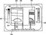
如图3到图5所示,在监视器107的显示画面上,除了在断层画面200上叠加显示弹性模量图像201之外,显示表示断层图像200的反射强度和画面上的亮度的对应的反射强度标度202、表示弹性模量和画面上的色调或亮度的对应的弹性模量标度203、心电或心音波形204等。图3到图5的断层图像200和弹性模量图像201作为一例,表示有粥肿302的血管的长轴剖面(血管壁301)。As shown in FIGS. 3 to 5 , on the display screen of the monitor 107 , in addition to superimposing and displaying the
下面,按照图2的定时来进行说明。Next, description will be made according to the timing in FIG. 2 .
首先,在实时模式中,断层图像200以15~30帧/秒连续更新,并一直显示最新的图像。另一方面,由于在断层图像200上叠加显示的弹性模量图像201根据一次心跳中组织的变形量和血压差来计算并生成弹性模量,所以与心跳同步地来进行更新,显示在一次心跳前的心跳期间得到的弹性模量图像201。弹性模量图像201与时相和位置关系对应(之后,称作“同步”)的断层图像200是该心跳期间中的任意一个图像,但是在此为心跳期间的最初的断层图像。First, in the real-time mode, the
即,参考图2,由于根据基于心跳期间C内的接收信号算出的弹性模量来生成弹性模量图像显示帧C,所以与弹性模量图像显示帧C同步的仅仅是心跳期间C的最初的断层图像显示帧2。因此,在实时模式中,如图3的显示画面所示,弹性模量图像201表示的弹性模量和断层图像200表示的组织结构不一致。That is, with reference to FIG. 2 , since the elastic modulus image display frame C is generated based on the elastic modulus calculated based on the received signal in the heartbeat period C, only the initial period of the heartbeat period C is synchronized with the elastic modulus image display frame C. The tomographic image shows
在实时模式中,将断层图像200和弹性模量图像201分别存储到断层图像存储器110和弹性模量图像存储器111中。另外,连续地图像显示由心电或心音测量部109得到的心音波形或心电波形,并存储到波形存储器112中。In the real-time mode, the
接着,在按下定格键,停止超声波发送,并进入到电影模式之后,如图4所示,将最新的弹性模量图像201和与其同步的断层图像200显示在监视器107上。参考图2,由于按下定格键的时刻的最新弹性模量图像201的显示帧D(下面,如201(D)所示)是根据心跳期间d的变形量生成的弹性模量图像,所以从断层图像存储器110中读取作为与其同步的断层图像200的心跳期间d的最初断层图像的显示帧7(200(7))后,将其显示到监视器107上。另外,如图4所示,在心电波形或心音波形204中,通过亮度或色调变化来强调显示表示生成了弹性模量图像显示帧201(D)的心跳期间CC(=d)的心电波形或心音波形(图中,用粗线表示)。Next, after pressing the freeze key to stop ultrasonic transmission and enter the movie mode, as shown in FIG. 4 , the latest
在电影模式中,可以通过返回/传送图像的操作来参考过去的图像。在本实施方式中,分别从弹性模量图像存储器111和断层图像存储器110中仅读取弹性模量图像显示帧和与其同步的断层图像显示帧后进行显示。参考图2,当执行图像返回操作时,从弹性模量图像存储器111中读取前一帧的弹性模量图像201的显示帧C(201(C)),从断层图像存储器110中读取与该弹性模量图像显示帧201(C)同步的断层图像200的显示帧2(200(2))来进行显示。In movie mode, you can refer to past images by returning/transferring images. In this embodiment, only the elastic modulus image display frame and the tomographic image display frame synchronized therewith are read from the elastic modulus image memory 111 and the tomographic image memory 110 respectively, and displayed. Referring to FIG. 2, when the image return operation is performed, the display frame C (201 (C)) of the
如图5所示,叠加显示弹性模量图像显示帧201(C)和断层图像显示帧200(2),通过亮度或色调变化来强调显示表示生成了所显示的弹性模量图像的心跳期间CC(=c)的心电波形或心音波形204的部分(图中,用虚线来表示)。As shown in FIG. 5 , an elastic modulus image display frame 201 (C) and a tomographic image display frame 200 (2) are superimposed and displayed, and the heartbeat period CC indicating that the displayed elastic modulus image is generated is highlighted by changing brightness or hue. (=c) part of the electrocardiographic waveform or the heart sound waveform 204 (indicated by a dotted line in the figure).
图2中,之后,若执行图像发送操作,则从弹性模量图像存储器111中读取弹性模量图像显示帧C的后一帧的弹性模量图像显示帧D,从断层图像存储器110中读取与弹性模量图像显示帧D同步的断层图像显示帧7,并显示在监视器107上。In FIG. 2 , afterward, if the image sending operation is performed, the elastic modulus image display frame D of the next frame of the elastic modulus image display frame C is read from the elastic modulus image memory 111, and the elastic modulus image display frame D of the next frame after the elastic modulus image display frame C is read from the tomographic image memory 110. The tomographic
如上所述,根据本实施方式,由于在实时模式中,实时地得到断层图像,所以可以容易进行定位等探针操作和增益等各种设定操作,在电影模式中,可以得到被检体组织的结构和弹性模量的时相和位置关系匹配的断层图像和弹性模量图像。As described above, according to this embodiment, since the tomographic image is obtained in real time in the real-time mode, various setting operations such as probe operations such as positioning and gain can be easily performed, and in the cine mode, it is possible to obtain The time phase and positional relationship of the structure and elastic modulus are matched to the tomographic image and elastic modulus image.
另外,通过进行弹性模量图像201向断层图像200的叠加的接通/截断,可以更容易地把握弹性模量和结构的关系。In addition, by performing ON/OFF superimposition of the
进一步,如图6所示,在断层图像200上仅显示由虚线所示的检查对象区域(ROI:Region Of Interest)208,而另一区域显示对应于ROI208的弹性模量图像201,可以得到相同的效果。Further, as shown in FIG. 6, on the
(实施方式2)(Embodiment 2)
接着,说明本发明的实施方式2的超声波诊断装置。Next, an ultrasonic diagnostic apparatus according to
另外,本实施方式的超声波诊断装置具有与在实施方式1的说明中参考的图1所示的结构相同的结构,与实施方式1不同点在于,二分割监视器107的显示画面,在一个显示区域(左侧显示区域)仅显示断层图像,在另一显示区域(右侧显示区域)上显示叠加了弹性模量图像201的断层图像。In addition, the ultrasonic diagnostic apparatus of this embodiment has the same structure as that shown in FIG. One area (left display area) displays only a tomographic image, and the other display area (right display area) displays a tomographic image superimposed with the
图7表示实时模式时的监视器107的显示画面,图8表示在电影模式下执行图像返回操作时的监视器107的显示画面。图9是表示在实时模式和电影模式中在监视器107上显示的心电或心音波形204、没有叠加弹性模量图像201的左侧断层图像205的显示帧、叠加了弹性模量图像201的右侧断层图像206的显示帧和弹性模量图像201的显示帧的时间图。FIG. 7 shows a display screen of the monitor 107 in the live mode, and FIG. 8 shows a display screen of the monitor 107 when an image return operation is performed in the movie mode. FIG. 9 shows an electrocardiographic or
图9中,叠加了弹性模量图像201的右侧断层图像206与实施方式1相同。另一方面,左侧断层图像205的显示帧在电影模式中,与弹性模量图像201的显示帧同步。In FIG. 9 , the right
这样,通过二分割显示画面,还可同时看到通过弹性模量图像201隐去的部分,在实时模式中,可以更容易地进行定位等探针操作和增益等各种设定操作,在电影模式中,可以同时得到时相一致的断层图像和弹性模量图像,所以比较两者,可以容易把握被检体组织的结构和弹性模量的关系。In this way, the part hidden by the
图10是表示本实施方式的变形例的实时模式和电影模式中、在监视器107上显示的心电或心音波形204、没有叠加弹性模量图像201的左侧断层图像205的显示帧、叠加了弹性模量图像201的右侧断层图像206的显示帧和弹性模量图像201的显示帧的时间图。FIG. 10 shows the display frame and superimposition of the electrocardiographic or
参考图10,在实时模式中,右侧断层图像206的显示帧2与弹性模量图像201的显示帧C同步。电影模式中的动作与图9的情况相同。Referring to FIG. 10 , in the real-time mode, the
如上所述,根据本发明的变形例,由于在实时模式中也在右侧断层图像206的右侧显示区域显示被检体组织的结构和弹性模量的位置关系匹配的断层图像和弹性模量图像201,所以可以马上得到诊断结果。As described above, according to the modified example of the present invention, since the right display area of the right
图11和图12是表示本实施方式的另一变形例的实时模式和电影模式中在监视器107上显示的心电或心音波形204、没有叠加弹性模量图像201的左侧断层图像205的显示帧、叠加了弹性模量图像201的右侧断层图像206的显示帧和弹性模量图像201的显示帧的时间图。图11和图12的实时模式中的动作分别与图9和图10的情况相同。下面,主要说明不同点。FIGS. 11 and 12 show the ECG or
首先,参照图11或图12,在按下定格键,进入到电影模式之后,在右侧断层图像206的右侧显示区域显示最新的弹性模量图像的显示帧D和与其对应的断层图像的显示帧7,但是在左侧断层图像205的左侧显示区域显示最新的断层图像的显示帧13。First, referring to FIG. 11 or FIG. 12, after pressing the freeze key to enter the movie mode, the display frame D of the latest elastic modulus image and the corresponding tomographic image are displayed in the right display area of the right
接着,若在电影模式中进行图像返回操作,则在左侧断层图像205的左侧显示区域,依次从断层图像存储器110中顺序读取并显示(显示帧12、11、10、...)前一帧的断层图像。另一方面,在右侧断层图像206的右侧显示区域,从弹性模量图像存储器111中读取包含在左侧断层图像205上当前显示的帧的心跳期间内得到的弹性模量图像显示帧201(D),从断层图像存储器110中读取与该弹性模量图像显示帧201(D)同步的断层图像显示帧206(7),来进行显示。Next, if the image return operation is performed in the cine mode, in the left display area of the left
但是,由于包含按下了定格键的定时的图像的心跳期间没有完成,所以这时显示之前得到的弹性模量图像显示帧和与其对应的断层图像显示帧。However, since the heartbeat period of the image including the timing at which the freeze key is pressed is not completed, the elastic modulus image display frame and the corresponding tomographic image display frame are displayed at this time.
因此,根据图11或图12所示的动作,每次进行图像返回操作时,在左侧断层图像205的左侧显示区域,从断层图像存储器110依次读取前一帧的断层图像来进行显示,但是在右侧断层图像206的右侧显示区域,在左侧断层图像205包含的心跳期间从d变为c时,即,左侧断层图像205从显示帧7更新为6来进行显示时,首先从弹性模量图像显示帧201(D)和与其对应的断层图像显示帧206(7)更新为弹性模量图像显示帧201(C)和与其对应的断层图像206(2)来进行显示。Therefore, according to the operation shown in FIG. 11 or FIG. 12 , every time the image return operation is performed, the tomographic image of the previous frame is sequentially read from the tomographic image memory 110 in the left display area of the left
图13表示执行图11或图12中的图像返回操作的结果,向弹性模量图像显示帧201(C)和与其对应的断层图像显示帧206(2)更新时的显示画面。在左侧断层图像205的左侧显示区域显示断层图像显示帧205(5),在右侧断层图像206的右侧显示区域叠加显示弹性模量图像显示帧201(C)和断层图像显示帧206(2)。另外,通过亮度或色调变化来强调显示表示生成了所显示的弹性模量图像的心跳期间的心电波形或心音波形204的部分(图中用粗线表示),在波形下显示表示左侧断层图像205的显示帧205(5)的时相的标记207。FIG. 13 shows the display screen when the elastic modulus image display frame 201(C) and the corresponding tomographic image display frame 206(2) are updated as a result of the image return operation in FIG. 11 or FIG. 12 . A tomographic image display frame 205(5) is displayed on the left display area of the left
如上所述,根据本实施方式的另一变形例,由于可以在左侧断层图像205的左侧显示区域以一帧为单位来显示断层图像,所以可以在用于弹性模量计算的心跳期间内详细调查被检体组织结构的动态变化。As described above, according to another modified example of the present embodiment, since the tomographic image can be displayed in units of one frame in the left display area of the left
另外,与实施方式1相同,通过可进行弹性模量图像201向右侧断层图像206的叠加的接通/截断,可以更容易地把握弹性模量和结构的关系。In addition, as in the first embodiment, since the superimposition of the
另外,在本发明的实施方式中,说明了计算对应于一次心跳的血压变化的被检体组织的变形量,并求出弹性模量的超声波诊断装置,但是本发明还可适用于求出根据由外部的压迫松弛或励振产生的接收信号的变化来计算出的、组织的变形量、变形率、弹性模量、粘度等被检体的组织特性的超声波诊断装置。这时,组织特性图像的生成周期最好为由外部的压迫松弛或励振的周期。In addition, in the embodiments of the present invention, an ultrasonic diagnostic device is described that calculates the amount of deformation of the subject's tissue corresponding to a change in blood pressure per heartbeat, and obtains the modulus of elasticity. However, the present invention can also be applied to obtain the An ultrasonic diagnostic device that calculates the tissue characteristics of the subject such as the amount of deformation, deformation rate, elastic modulus, and viscosity of the tissue from changes in received signals due to external compression, relaxation, or excitation. In this case, the generation period of the tissue characteristic image is preferably a period of relaxation or excitation by external pressure.
另外,在监视器107的显示画面上显示的一维波形并不限于心电和心音,可以实时显示血压波形和血管内径变化波形等的表示被检体信息的波形、组织追踪波形和组织厚度变化波形、变形量波形等表示用于求出弹性模量的中途经过的波形等所有种类的关联波形。由此,在显示表示被检体信息的波形的情况下,可以不另外参考显示装置,而从一个画面中得到需要的被检体信息,在显示表示中途经过的波形的情况下,可以详细观察用于求出最终的组织特性的信息。即,通过显示包含与断层图像和组织特性图像的至少一个对应的信息的波形,可以有效参考与所显示的图像有关的信息。进一步,作为强调显示生成了弹性模量图像的期间的方法,并不限于亮度或色调的变化,可以使用粗线、细线、虚线等线型的变化或用四边型、圆型、括号等包围的等所有强调方法。由此,可以一眼识别生成了弹性模量图像的期间的波形信息。In addition, the one-dimensional waveforms displayed on the display screen of the monitor 107 are not limited to electrocardiograms and heart sounds, and waveforms representing subject information such as blood pressure waveforms and blood vessel inner diameter change waveforms, tissue tracking waveforms, and tissue thickness changes can be displayed in real time. The waveform, the deformation amount waveform, and the like represent all kinds of related waveforms, such as a waveform passing through for obtaining the modulus of elasticity. Thus, when displaying a waveform showing subject information, necessary subject information can be obtained on one screen without separately referring to the display device, and when displaying a waveform showing halfway progress, it is possible to observe in detail Information used to obtain the final tissue characteristics. That is, by displaying a waveform containing information corresponding to at least one of a tomographic image and a tissue property image, it is possible to effectively refer to information related to the displayed image. Furthermore, as a method of emphasizing the period during which the elastic modulus image was generated, it is not limited to changes in brightness or hue, and changes in line types such as thick lines, thin lines, and dashed lines, or enclosing them with squares, circles, and brackets, etc. can be used. The etc. all emphasize methods. Thereby, the waveform information of the period in which the elastic modulus image was generated can be recognized at a glance.
产业上的可利用性Industrial availability
根据本发明,由于可以叠加显示时相和位置关系匹配的断层图像和组织特性图像,所以可以提供可容易且详细地观察被检体组织的结构和特性的关系的优良的超声波诊断装置。According to the present invention, since it is possible to superimpose and display a tomographic image and a tissue characteristic image matched in phase and positional relationship, it is possible to provide an excellent ultrasonic diagnostic apparatus capable of easily and detailedly observing the relationship between the structure and the characteristic of the object tissue.
Claims (9)
Translated fromChineseApplications Claiming Priority (3)
| Application Number | Priority Date | Filing Date | Title |
|---|---|---|---|
| JP169909/2003 | 2003-06-13 | ||
| JP2003169909 | 2003-06-13 | ||
| PCT/JP2004/008468WO2004110280A1 (en) | 2003-06-13 | 2004-06-10 | Ultrasonic diagnosis device |
Publications (2)
| Publication Number | Publication Date |
|---|---|
| CN1805713Atrue CN1805713A (en) | 2006-07-19 |
| CN1805713B CN1805713B (en) | 2010-04-28 |
Family
ID=33549390
Family Applications (1)
| Application Number | Title | Priority Date | Filing Date |
|---|---|---|---|
| CN2004800165206AExpired - Fee RelatedCN1805713B (en) | 2003-06-13 | 2004-06-10 | Ultrasonic diagnostic apparatus |
Country Status (6)
| Country | Link |
|---|---|
| US (1) | US7455640B2 (en) |
| EP (1) | EP1637082B1 (en) |
| JP (1) | JP4509027B2 (en) |
| CN (1) | CN1805713B (en) |
| DE (1) | DE602004032138D1 (en) |
| WO (1) | WO2004110280A1 (en) |
Cited By (5)
| Publication number | Priority date | Publication date | Assignee | Title |
|---|---|---|---|---|
| CN102413771A (en)* | 2009-04-24 | 2012-04-11 | 株式会社日立医疗器械 | Ultrasonic imaging device |
| CN102811665A (en)* | 2010-03-19 | 2012-12-05 | 株式会社日立医疗器械 | Ultrasonic diagnostic device and ultrasonic image display method |
| CN103211623A (en)* | 2013-05-15 | 2013-07-24 | 晁彦公 | Real-time monitoring system of B ultrasonic clinical information |
| CN106963424A (en)* | 2017-03-15 | 2017-07-21 | 深圳大学 | System and method for detecting arterial vessel viscoelasticity |
| CN114556144A (en)* | 2019-08-08 | 2022-05-27 | 布弗莱运营公司 | Method and apparatus for collecting ultrasound images |
Families Citing this family (24)
| Publication number | Priority date | Publication date | Assignee | Title |
|---|---|---|---|---|
| US8118746B2 (en)* | 2003-09-12 | 2012-02-21 | Hitachi Medical Corporation | Ultrasonic diagnostic apparatus |
| JP4657106B2 (en)* | 2003-11-21 | 2011-03-23 | 株式会社日立メディコ | Ultrasonic diagnostic equipment |
| WO2005122906A1 (en)* | 2004-06-18 | 2005-12-29 | Hitachi Medical Corporation | Ultrasonic diagnositic apparatus |
| WO2006011504A1 (en)* | 2004-07-28 | 2006-02-02 | Matsushita Electric Industrial Co., Ltd. | Ultrasonograph and ultrasonograph control method |
| EP1800604B1 (en)* | 2004-10-08 | 2009-09-09 | Hitachi Medical Corporation | Ultrasonic diagnosis device |
| WO2006106852A1 (en)* | 2005-03-30 | 2006-10-12 | Hitachi Medical Corporation | Ultrasonograph |
| WO2006121031A1 (en)* | 2005-05-09 | 2006-11-16 | Hitachi Medical Corporation | Ultrasonograph and ultrasonic image display method |
| JP4787570B2 (en)* | 2005-08-17 | 2011-10-05 | 日立アロカメディカル株式会社 | Ultrasonic diagnostic equipment |
| WO2007034738A1 (en)* | 2005-09-20 | 2007-03-29 | Matsushita Electric Industrial Co., Ltd. | Ultrasonic diagnostic equipment |
| WO2007046272A1 (en)* | 2005-10-19 | 2007-04-26 | Hitachi Medical Corporation | Ultrasonograph for creating elastic image |
| WO2007080870A1 (en)* | 2006-01-11 | 2007-07-19 | Matsushita Electric Industrial Co., Ltd. | Ultrasonograph |
| WO2007122698A1 (en)* | 2006-04-18 | 2007-11-01 | Panasonic Corporation | Ultrasonograph |
| EP2030573A4 (en)* | 2006-06-06 | 2013-02-27 | Hitachi Medical Corp | Ultrasonographic device |
| JP5242092B2 (en)* | 2007-07-11 | 2013-07-24 | 株式会社東芝 | Ultrasonic diagnostic equipment |
| US8485976B2 (en)* | 2008-08-29 | 2013-07-16 | Hitachi Medical Corporation | Ultrasonic diagnostic apparatus |
| US8083406B2 (en) | 2009-01-29 | 2011-12-27 | The Invention Science Fund I, Llc | Diagnostic delivery service |
| US8130904B2 (en) | 2009-01-29 | 2012-03-06 | The Invention Science Fund I, Llc | Diagnostic delivery service |
| KR101121245B1 (en)* | 2009-08-20 | 2012-03-23 | 삼성메디슨 주식회사 | Ultrasound system and method for providing elastic change information |
| DE102010009295B4 (en)* | 2010-02-25 | 2019-02-21 | Siemens Healthcare Gmbh | Method for displaying a region to be examined and / or treated |
| JP5294340B2 (en) | 2010-10-27 | 2013-09-18 | ジーイー・メディカル・システムズ・グローバル・テクノロジー・カンパニー・エルエルシー | Ultrasonic diagnostic equipment |
| JP5209026B2 (en)* | 2010-10-27 | 2013-06-12 | ジーイー・メディカル・システムズ・グローバル・テクノロジー・カンパニー・エルエルシー | Ultrasonic diagnostic equipment |
| JP2011173008A (en)* | 2011-06-14 | 2011-09-08 | Hitachi Medical Corp | Ultrasonograph |
| KR102379513B1 (en)* | 2020-07-08 | 2022-03-25 | 재단법인대구경북과학기술원 | Imaging System |
| JP7475313B2 (en)* | 2021-04-19 | 2024-04-26 | 富士フイルムヘルスケア株式会社 | Ultrasound diagnostic system, ultrasound diagnostic device, and diagnostic support server |
Family Cites Families (14)
| Publication number | Priority date | Publication date | Assignee | Title |
|---|---|---|---|---|
| US5619995A (en) | 1991-11-12 | 1997-04-15 | Lobodzinski; Suave M. | Motion video transformation system and method |
| JP3268396B2 (en) | 1992-05-15 | 2002-03-25 | 石原 謙 | Ultrasound diagnostic equipment |
| JP3474229B2 (en) | 1993-09-09 | 2003-12-08 | フクダ電子株式会社 | Ultrasound diagnostic equipment |
| JP3652791B2 (en) | 1996-06-24 | 2005-05-25 | 独立行政法人科学技術振興機構 | Ultrasonic diagnostic equipment |
| EP0961577A1 (en) | 1997-11-18 | 1999-12-08 | Koninklijke Philips Electronics N.V. | Method for the processing of signals relating to an object having moving parts and echographic device for carrying out this method |
| JP4201396B2 (en)* | 1998-08-20 | 2008-12-24 | 株式会社日立メディコ | Ultrasonic diagnostic equipment |
| JP3398080B2 (en)* | 1999-02-10 | 2003-04-21 | 科学技術振興事業団 | Vascular lesion diagnostic system and diagnostic program storage medium |
| US6398736B1 (en)* | 1999-03-31 | 2002-06-04 | Mayo Foundation For Medical Education And Research | Parametric imaging ultrasound catheter |
| US6371912B1 (en)* | 2000-04-05 | 2002-04-16 | Duke University | Method and apparatus for the identification and characterization of regions of altered stiffness |
| US6558324B1 (en)* | 2000-11-22 | 2003-05-06 | Siemens Medical Solutions, Inc., Usa | System and method for strain image display |
| US6749571B2 (en)* | 2002-09-19 | 2004-06-15 | Wisconsin Alumni Research Foundation | Method and apparatus for cardiac elastography |
| JP4257696B2 (en)* | 2002-10-28 | 2009-04-22 | 株式会社日立メディコ | Ultrasonic device |
| US6979294B1 (en)* | 2002-12-13 | 2005-12-27 | California Institute Of Technology | Split-screen display system and standardized methods for ultrasound image acquisition and processing for improved measurements of vascular structures |
| JP2004215968A (en) | 2003-01-16 | 2004-08-05 | Matsushita Electric Ind Co Ltd | Ultrasonic diagnostic apparatus and control method of ultrasonic diagnostic apparatus |
- 2004
- 2004-06-10JPJP2005506986Apatent/JP4509027B2/ennot_activeExpired - Fee Related
- 2004-06-10WOPCT/JP2004/008468patent/WO2004110280A1/ennot_activeCeased
- 2004-06-10EPEP04736585Apatent/EP1637082B1/ennot_activeExpired - Lifetime
- 2004-06-10DEDE602004032138Tpatent/DE602004032138D1/ennot_activeExpired - Lifetime
- 2004-06-10USUS10/560,375patent/US7455640B2/ennot_activeExpired - Fee Related
- 2004-06-10CNCN2004800165206Apatent/CN1805713B/ennot_activeExpired - Fee Related
Cited By (7)
| Publication number | Priority date | Publication date | Assignee | Title |
|---|---|---|---|---|
| CN102413771A (en)* | 2009-04-24 | 2012-04-11 | 株式会社日立医疗器械 | Ultrasonic imaging device |
| CN102413771B (en)* | 2009-04-24 | 2014-04-16 | 株式会社日立医疗器械 | Ultrasonic imaging device |
| CN102811665A (en)* | 2010-03-19 | 2012-12-05 | 株式会社日立医疗器械 | Ultrasonic diagnostic device and ultrasonic image display method |
| CN102811665B (en)* | 2010-03-19 | 2015-05-27 | 株式会社日立医疗器械 | Ultrasound diagnostic device and ultrasound image display method |
| CN103211623A (en)* | 2013-05-15 | 2013-07-24 | 晁彦公 | Real-time monitoring system of B ultrasonic clinical information |
| CN106963424A (en)* | 2017-03-15 | 2017-07-21 | 深圳大学 | System and method for detecting arterial vessel viscoelasticity |
| CN114556144A (en)* | 2019-08-08 | 2022-05-27 | 布弗莱运营公司 | Method and apparatus for collecting ultrasound images |
Also Published As
| Publication number | Publication date |
|---|---|
| CN1805713B (en) | 2010-04-28 |
| EP1637082A1 (en) | 2006-03-22 |
| DE602004032138D1 (en) | 2011-05-19 |
| US20060173309A1 (en) | 2006-08-03 |
| WO2004110280A1 (en) | 2004-12-23 |
| JPWO2004110280A1 (en) | 2006-07-27 |
| US7455640B2 (en) | 2008-11-25 |
| EP1637082B1 (en) | 2011-04-06 |
| JP4509027B2 (en) | 2010-07-21 |
| EP1637082A4 (en) | 2008-07-30 |
Similar Documents
| Publication | Publication Date | Title |
|---|---|---|
| CN1805713A (en) | Ultrasonic diagnostic device | |
| US7575551B2 (en) | Biological signal monitor device | |
| US9568598B2 (en) | Ultrasonic diagnostic apparatus and program | |
| US7588538B2 (en) | Ultrasonic diagnostic equipment and image processing apparatus | |
| WO2016067072A1 (en) | Imaging methods and apparatuses for performing shear wave elastography imaging | |
| IL216512A (en) | Method and apparatus for measuring heart contractility | |
| JP2004073287A (en) | Ultrasonic diagnostic apparatus, ultrasonic image display apparatus, and ultrasonic image display method | |
| WO2014081006A1 (en) | Ultrasonic diagnostic device, image processing device, and image processing method | |
| WO2003077765A1 (en) | Ultrasonographic system and ultrasonography | |
| US20070083116A1 (en) | Ultrasonic diagnostic apparatus | |
| WO2011013713A1 (en) | Ultrasonograph and urtrasonic processing device | |
| JP2018511447A (en) | Tissue morphology and elasticity information processing method, and elasticity detection apparatus | |
| CN1757380B (en) | Ultrasonic imaging device and ultrasonic imaging method | |
| JP2007222533A (en) | Ultrasonic diagnostic apparatus and ultrasonic image processing method | |
| WO2006098354A1 (en) | Ultrasonic diagnostic equipment and method for controlling same | |
| JPWO2007114305A1 (en) | Image processing apparatus, ultrasonic imaging apparatus including the same, and image processing method | |
| JPH0779974A (en) | Ultrasonic diagnostic equipment | |
| JPWO2007080870A1 (en) | Ultrasonic diagnostic equipment | |
| JP4921816B2 (en) | Ultrasonic diagnostic apparatus and control program therefor | |
| JP2008188288A (en) | Ultrasonic diagnostic apparatus and ultrasonic image display apparatus | |
| JP5179801B2 (en) | Ultrasonic image display method and apparatus | |
| JP2005027941A (en) | Ultrasonic diagnostic equipment | |
| JP2007195882A (en) | Ultrasonic diagnostic equipment | |
| JPWO2006126485A1 (en) | Ultrasonic diagnostic equipment | |
| JP2025015216A (en) | Ultrasonic diagnostic device and echo image display method |
Legal Events
| Date | Code | Title | Description |
|---|---|---|---|
| C06 | Publication | ||
| PB01 | Publication | ||
| C10 | Entry into substantive examination | ||
| SE01 | Entry into force of request for substantive examination | ||
| C14 | Grant of patent or utility model | ||
| GR01 | Patent grant | ||
| ASS | Succession or assignment of patent right | Owner name:KONICA MINOLTA OPTO INC. Free format text:FORMER OWNER: MATSUSHITA ELECTRIC INDUSTRIAL CO, LTD. Effective date:20140320 | |
| C41 | Transfer of patent application or patent right or utility model | ||
| TR01 | Transfer of patent right | Effective date of registration:20140320 Address after:Tokyo, Japan, Japan Patentee after:Konica Minolta Opto, Inc. Address before:Osaka Japan Patentee before:Matsushita Electric Industrial Co., Ltd. | |
| CF01 | Termination of patent right due to non-payment of annual fee | ||
| CF01 | Termination of patent right due to non-payment of annual fee | Granted publication date:20100428 Termination date:20200610 |