CN1801069A - Capacitive touch panel and detection method thereof - Google Patents
Capacitive touch panel and detection method thereofDownload PDFInfo
- Publication number
- CN1801069A CN1801069ACN 200410103139CN200410103139ACN1801069ACN 1801069 ACN1801069 ACN 1801069ACN 200410103139CN200410103139CN 200410103139CN 200410103139 ACN200410103139 ACN 200410103139ACN 1801069 ACN1801069 ACN 1801069A
- Authority
- CN
- China
- Prior art keywords
- axis
- touch panel
- capacitive touch
- phase
- detection method
- Prior art date
- Legal status (The legal status is an assumption and is not a legal conclusion. Google has not performed a legal analysis and makes no representation as to the accuracy of the status listed.)
- Granted
Links
- 238000001514detection methodMethods0.000titleclaimsdescription24
- 238000000034methodMethods0.000claimsdescription8
- 230000001419dependent effectEffects0.000claimsdescription2
- 230000006698inductionEffects0.000abstractdescription3
- 238000010586diagramMethods0.000description18
- 230000000737periodic effectEffects0.000description8
- 238000006243chemical reactionMethods0.000description5
- 230000006870functionEffects0.000description4
- 230000001939inductive effectEffects0.000description2
- 230000010354integrationEffects0.000description1
- 238000004519manufacturing processMethods0.000description1
- 239000011159matrix materialSubstances0.000description1
- 238000004806packaging method and processMethods0.000description1
Images


Landscapes
- Position Input By Displaying (AREA)
Abstract
Description
Translated fromChinese技术领域technical field
本发明涉及一种电容式触控板,特别是关于一种双轴非等间隔交错式感应扫描的电容式触控板。The invention relates to a capacitive touch panel, in particular to a capacitive touch panel with two-axis non-equal interval interlaced induction scanning.
背景技术Background technique
电容式触控板已经广泛地用作计算机系统的指向装置。传统的电容式触控板通过由检测矩阵式配置的许多感应器的电容变化量,判断手指碰触其面板的位置,并由手指碰触的位置的变化判断其移动量及移动速度。在鼠标Z轴上的应用如图1A及图1B所示,在电容式触控板10上具有多个感应器12,每个感应器12各自对应一独立的迹线,该迹线X1-X8构成一排扫描线16,当手指碰触到电容式触控板10时,经扫描该感应器12产生电容变化量如图1B所示,据以判断手指在面板上的位置,例如图1B中的分布表示手指在迹线X5连接的感应器上。当手指在触控板10上滑动时,产生电容变化量最大的位置也随之移动,由手指碰触的位置的变化判断其移动量及移动速度,经转换后送出Z轴信号。Capacitive touchpads have been widely used as pointing devices for computer systems. The traditional capacitive touch panel judges the position where the finger touches the panel by detecting the capacitance change of many sensors arranged in a matrix, and judges the movement amount and speed by the change of the finger touch position. The application on the Z axis of the mouse is shown in Figure 1A and Figure 1B, there are multiple sensors 12 on the capacitive touch panel 10, and each sensor 12 corresponds to an independent trace respectively, and the traces X1-X8 A row of scanning lines 16 is formed. When a finger touches the capacitive touch panel 10, the sensor 12 is scanned to generate a capacitance change as shown in FIG. 1B, so as to determine the position of the finger on the panel, for example, in FIG. The distribution of indicates that the finger is on the sensor connected by trace X5. When the finger slides on the touch panel 10, the position with the largest capacitance change also moves, and the movement amount and speed are judged by the change of the position touched by the finger, and the Z-axis signal is sent after conversion.
然而,当感应器12的数目愈多时,其对应迹线的数目就愈多,而且触控板10的控制器14内的应用电路也跟着复杂,因此芯片的尺寸、其制造与封装成本也相对提高。However, when the number of sensors 12 increases, the number of corresponding traces increases, and the application circuit in the controller 14 of the touch panel 10 is also complicated, so the size of the chip, its manufacturing and packaging costs are also relatively large. improve.
发明内容Contents of the invention
本发明要解决的技术问题是提供一种电容式触控板及其检测方法。The technical problem to be solved by the present invention is to provide a capacitive touch panel and a detection method thereof.
本发明要解决的另一个技术问题是提供一种减少迹线数目的电容式触控板。Another technical problem to be solved by the present invention is to provide a capacitive touch panel with a reduced number of traces.
本发明要解决的又一个技术问题是提供一种应用电路简单、成本低廉且易与一般Z轴鼠标电路整合的电容式触控板。Another technical problem to be solved by the present invention is to provide a capacitive touch panel with simple application circuit, low cost and easy integration with general Z-axis mouse circuit.
根据本发明,一种电容式触控板包括二轴各连接多个感应器,该感应器以非等间隔交错方式排列。According to the present invention, a capacitive touch panel includes a plurality of sensors connected to each of two axes, and the sensors are arranged in a staggered manner at non-equal intervals.
根据本发明,一种电容式触控板的检测方法,该电容式触控板含有第一及第二轴以及以非等间隔交错方式排列的多个感应器分别连接该第一及第二轴,该方法包括检测该感应器的电容变化量,以产生第一轴与第二轴信号,以及根据该第一轴与第二轴信号衍生的波形相位判断在该电容式触控板上滑动的移动方向。According to the present invention, a detection method of a capacitive touch panel, the capacitive touch panel includes first and second axes and a plurality of sensors arranged in a staggered manner at non-equal intervals respectively connected to the first and second axes , the method includes detecting the capacitance variation of the sensor to generate first-axis and second-axis signals, and judging the movement of sliding on the capacitive touch panel according to the waveform phase derived from the first-axis and second-axis signals direction of movement.
根据本发明,一种应用于鼠标Z轴的电容式触控板,包括二轴以及以非等间隔交错方式排列的多个感应器分别连接该二轴,该感应器产生的电容变化量在该二轴上产生相位领先或落后的Z轴信号籍以对一视窗的滚动条进行卷动。According to the present invention, a capacitive touch panel applied to the Z-axis of a mouse includes two axes and a plurality of sensors arranged in a staggered manner at non-equal intervals respectively connected to the two axes, and the capacitance variation generated by the sensors is within the range of the two axes. A Z-axis signal with a leading or lagging phase is generated on the two axes to scroll the scroll bar of a window.
根据本发明的电容式触控板及其检测方法,只要手指在电容式触控板上滑动即可产生周期性信号,不需经繁复的电路运算便可轻易达成鼠标Z轴的设计,解决公知的多迹线单一式感应扫描需要经过极为复杂的电路运算与转换过程方能仿真送出Z轴信号的问题。According to the capacitive touch panel and its detection method of the present invention, as long as the finger slides on the capacitive touch panel, periodic signals can be generated, and the Z-axis design of the mouse can be easily achieved without complicated circuit calculations, solving the problem of conventional The multi-trace single-type inductive scanning needs to go through extremely complicated circuit calculation and conversion process to simulate the problem of sending out the Z-axis signal.
此外,根据本发明产生的周期性信号所设计的鼠标Z轴具有与滚轮鼠标相同的结构,因此可轻易与一般Z轴鼠标的电路整合在一起,不需再经过复杂的电路运算及转换,且不必使用大量的迹线,使得应用电路较为简单、成本下降。In addition, the Z-axis of the mouse designed according to the periodic signal generated by the present invention has the same structure as the wheel mouse, so it can be easily integrated with the circuit of a general Z-axis mouse without complex circuit calculations and conversions, and Not having to use a large number of traces makes the application circuit simpler and lower in cost.
附图说明Description of drawings
图1A为公知的电容式触控板的示意图。FIG. 1A is a schematic diagram of a known capacitive touch panel.
图1B为图1A的电容式触控板检测产生的电容变化量的示意图。FIG. 1B is a schematic diagram of the amount of capacitance change generated by the detection of the capacitive touch panel in FIG. 1A .
图2为根据本发明的电容式触控板的示意图。FIG. 2 is a schematic diagram of a capacitive touch panel according to the present invention.
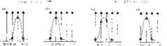
图3中(a)为图2的电容式触控板检测产生的电容变化量的示意图。(a) of FIG. 3 is a schematic diagram of the capacitance variation generated by the detection of the capacitive touch panel of FIG. 2 .
图3中(b)为图2的电容式触控板检测产生的电容变化量的示意图。(b) in FIG. 3 is a schematic diagram of the amount of capacitance change generated by the detection of the capacitive touch panel in FIG. 2 .
图3中(c)为图2的电容式触控板检测产生的电容变化量的示意图。(c) in FIG. 3 is a schematic diagram of the amount of capacitance change generated by the detection of the capacitive touch panel in FIG. 2 .
图3中(d)为图2的电容式触控板检测产生的电容变化量的示意图。(d) in FIG. 3 is a schematic diagram of the capacitance variation generated by the detection of the capacitive touch panel in FIG. 2 .
图4A为图2电容式触控板产生的相位领先波形的示意图。FIG. 4A is a schematic diagram of a phase-leading waveform generated by the capacitive touch panel in FIG. 2 .
图4B为图2电容式触控板产生的相位落后波形的示意图。FIG. 4B is a schematic diagram of a phase-lag waveform generated by the capacitive touch panel in FIG. 2 .
图5为图2的电容式触控板应用于鼠标的Z轴机构的示意图。FIG. 5 is a schematic diagram of a Z-axis mechanism where the capacitive touch panel of FIG. 2 is applied to a mouse.
图6为本发明的系统方块图。FIG. 6 is a system block diagram of the present invention.
图7为图6中的模拟方块的功能方块图。FIG. 7 is a functional block diagram of the analog block in FIG. 6 .
图8为根据本发明的另一实施例示意图。Fig. 8 is a schematic diagram according to another embodiment of the present invention.
图9为根据本发明的又一实施例示意图。Fig. 9 is a schematic diagram according to yet another embodiment of the present invention.
10电容式触控板 12感应器10 capacitive touch panel 12 sensors
14控制器 16扫描线14 controllers 16 scan lines
20电容式触控板 22轴20
24轴 26感应器24
28感应器 50鼠标28
52Z轴机构 602Z轴感测器52Z-axis mechanism 602Z-axis sensor
604信号处理单元 606模拟方块604 signal processing unit 606 analog block
608微控制器 610SRAM608 Microcontroller 610SRAM
612R0M 614数字方块612R0M 614 digital cubes
616鼠标 618Z轴机构616 mouse 618 Z-axis mechanism
620连接线 622计算机620 connection line 622 computer
702多任务器 704电流源702 multi-tasker 704 current source
706方大器 708数字至模拟转换器706 Fangda Device 708 Digital to Analog Converter
710模拟至数字转换器 712数字方块710 Analog to Digital Converter 712 Digital Cube
80电容式触控板 82轴80
84轴 86轴84
88a感应器 88b感应器
88C感应器 90电容式触控板
91轴 92轴91
93轴 94轴93
95a感应器 95b感应器受器
95c感应器 96感应器
具体实施方式Detailed ways
根据本发明,一种双轴非等间隔交错式感应扫描的电容式触控板如图2所示,电容式触控板20上具有轴22与24,以及多个感应器26与28以非等间隔交错方式排列,感应器26连接轴22,感应器28连接轴24。According to the present invention, a capacitive touch panel with two-axis non-equal spaced interlaced induction scanning is shown in FIG. Arranged in a staggered manner at equal intervals, the
参照图2,一种检测电容式触控板20的方法,包括检测轴22及24上以非等间隔交错方式排列的感应器26及28的电容变化量,产生轴22及24信号,接着根据该电容变化量设定及改变电压的准位,产生轴22及24的波形相位,最后根据该波形相位判断在电容式触控板20上的滑动的移动方向。With reference to Fig. 2, a kind of method for detecting
图3(a)-(d)为检测电容式触控板20所产生的电容变化量的示意图。当手指从电容式触控板20上方往下滑动时,首先触碰到没有感应器的位置,所产生的电容变化量如(a)所示,接着触碰到感应器26,所产生的电容变化量如(b)所示,之后同时触碰到感应器26及28,所产生的电容变化量如(c)所示,然后再触碰到感应器28,所产生的电容变化量如(d)所示,最后再触碰到没有感应器的位置,所产生的电容变化量如(a)所示,如此即产生一个由上往下滑动的周期信号。同样地,当手指从电容式触控板20下方往上滑动时,首先触碰到没有感应器的位置,所产生的电容变化量如(a)所示,接着触碰到感应器28,所产生的电容变化量如(d)所示,之后同时触碰到感应器28及26,所产生的电容变化量如(c)所示,然后再触碰到感应器26,所产生的电容变化量如(b)所示,最后再触碰到没有感应器的位置,所产生的电容变化量如(a)所示,产生一个由下往上滑动的周期信号。根据由上往下滑动的周期信号产生一个相位领先的电压波形如图4A所示,以及根据由下往上滑动的周期信号产生一个相位落后的电压波形如图4B所示,如图4A及图4B所示的相依信号即类似于鼠标Z轴滚轮的特性,因此根据本发明的电容式触控板及其检测方法,只要手指在电容式触控板上滑动即可产生周期性信号,不需经繁复的电路运算便可轻易达成鼠标Z轴的设计,解决公知的多迹线单一式感应扫描需要经过极为复杂的电路运算与转换过程方能仿真送出Z轴信号的问题。3( a )-( d ) are schematic diagrams of detecting the capacitance variation generated by the
此外,根据本发明产生的周期性信号所设计的鼠标Z轴具有与滚轮鼠标相同的结构,因此可轻易与一般Z轴鼠标的电路整合在一起,不需再经过复杂的电路运算及转换,且不必使用大量的迹线,使得应用电路较为简单、成本下降。In addition, the Z-axis of the mouse designed according to the periodic signal generated by the present invention has the same structure as the wheel mouse, so it can be easily integrated with the circuit of a general Z-axis mouse without complex circuit calculations and conversions, and Not having to use a large number of traces makes the application circuit simpler and lower in cost.
图5为图2的电容式触控板20应用在鼠标50的z轴机构52的示意图。配合电容式触控板的检测方法判断手指滑动的移动方向,并以移动方向控制在窗口上的滚动条的卷动功能。FIG. 5 is a schematic diagram of the
图6为本发明的系统方块图,本系统包括Z轴传感器602以及信号处理单元604,Z轴传感器602感应到的信号经由信号处理单元604中的模拟方块606、数字方块614、徽控制器608、SRAM610及ROM612处理后产生一Z轴信号,该Z轴信号可应用于鼠标616的Z轴机构618中,并通过由连接线620经由USB或PS/2接口与计算机622连接,达到在计算机622视窗上的滚动条的卷动功能。6 is a system block diagram of the present invention, the system includes a Z-axis sensor 602 and a signal processing unit 604, and the signal sensed by the Z-axis sensor 602 passes through the analog block 606, the digital block 614, and the emblem controller 608 in the signal processing unit 604. , SRAM610 and ROM612 produce a Z-axis signal after processing, and this Z-axis signal can be applied in the Z-axis mechanism 618 of mouse 616, and is connected with computer 622 through USB or PS/2 interface by connecting line 620, reaches computer 622 The scroll function of the scroll bar on the window.
图7为图6中模拟方块606的功能方块图,包括二Z轴信号Z1、Z2输入一多任务器702,一电流源704连接多任务器702的输出,以提供电流产生电压信号V1及V2,一数字至模拟转换器708提供一电压位准给放大器706,一模拟至数字转换器710连接放大器706的输出端,以将放大器706输出的模拟信号转换为数字信号,并通过由数字方块712交由微控制器608处理,以产生相位领先或相位落后的电压波形。7 is a functional block diagram of the analog block 606 in FIG. 6, including two Z-axis signals Z1, Z2 input to a
根据本发明,另一实施例的电容式触控板如图8所示,电容式触控板80在轴82及84之间增加辅助轴86,同样地,连接轴82与84的多个感应器88a与88b以非等间隔交错方式排列,连接轴86的多个感应器88C穿插于感应器88a与88b之间,轴82与84的功能与图2中轴22与24的功能相同,而检测感应器88C所产生轴86的信号可做为轴82与84的参考值,例如信号大小的基准。According to the present invention, another embodiment of the capacitive touch panel is shown in FIG. The
根据本发明,又一实施例的电容式触控板如图9所示,电容式触控板90上具有轴91、92、93及94,其中轴94可以有任意个。连接轴91与92的多个感应器95a与95b以非等间隔交错方式排列,轴93连接多个感应器95C介于感应器95a与95b之间,轴94连接的多个感应器96亦介于感应器95a与95b之间,图中为了清楚表示的缘故,被移至右侧。轴91与92的功能与图2中轴22与24的功能相同,检测感应器95C所产生轴93的信号可做为轴91与92的参考值,而检测感应器96所产生轴94的信号可做为辅助参考判断轴91与92的电容变化量。According to the present invention, a capacitive touch panel according to another embodiment is shown in FIG. 9 . The
如图8与图9所示的电容式触控板80及90,可减少手指在电容式触控板上滑动时信号的损失,增加电容式触控板的精确度。The
以上对于本发明的较佳实施例所作的叙述是为了阐明本发明的技术特征,而无意限定本发明的权利要求范围,基于以上的教导或从本发明的实施例学习而作修改或变化是可能的,实施例系为解说本发明的原理以及让熟习该项技术者以各种实施例利用本发明在实际应用上而选择及叙述,本发明的技术思想企图由以下的申请专利范围及其均等来决定。The above description of the preferred embodiments of the present invention is to clarify the technical characteristics of the present invention, and has no intention to limit the scope of the claims of the present invention. It is possible to modify or change based on the above teaching or learning from the embodiments of the present invention. The embodiment is selected and described for explaining the principle of the present invention and allowing those skilled in the art to utilize the present invention in practical application with various embodiments. to decide.
Claims (13)
Translated fromChinesePriority Applications (1)
| Application Number | Priority Date | Filing Date | Title |
|---|---|---|---|
| CNB2004101031395ACN100368975C (en) | 2004-12-31 | 2004-12-31 | Capacitive touch pad and detection method thereof |
Applications Claiming Priority (1)
| Application Number | Priority Date | Filing Date | Title |
|---|---|---|---|
| CNB2004101031395ACN100368975C (en) | 2004-12-31 | 2004-12-31 | Capacitive touch pad and detection method thereof |
Publications (2)
| Publication Number | Publication Date |
|---|---|
| CN1801069Atrue CN1801069A (en) | 2006-07-12 |
| CN100368975C CN100368975C (en) | 2008-02-13 |
Family
ID=36811108
Family Applications (1)
| Application Number | Title | Priority Date | Filing Date |
|---|---|---|---|
| CNB2004101031395AExpired - Fee RelatedCN100368975C (en) | 2004-12-31 | 2004-12-31 | Capacitive touch pad and detection method thereof |
Country Status (1)
| Country | Link |
|---|---|
| CN (1) | CN100368975C (en) |
Cited By (7)
| Publication number | Priority date | Publication date | Assignee | Title |
|---|---|---|---|---|
| CN101661359B (en)* | 2009-10-10 | 2011-06-01 | 友达光电股份有限公司 | Capacitive touch detection system and its detection signal receiving and waveform shaping module |
| CN101488068B (en)* | 2009-02-13 | 2012-05-09 | 苏州达方电子有限公司 | Touch control apparatus and its touch control method |
| CN101866248B (en)* | 2009-04-16 | 2012-07-04 | 义隆电子股份有限公司 | Two-layer circuit board structure for capacitive touch pad and manufacturing method thereof |
| CN102566841A (en)* | 2008-10-31 | 2012-07-11 | 宸鸿光电科技股份有限公司 | Structure of Curved Capacitive Touch Panel |
| CN102636718A (en)* | 2012-05-10 | 2012-08-15 | 意力(广州)电子科技有限公司 | Mutual capacitance touch screen detection method |
| CN101676846B (en)* | 2008-09-16 | 2012-09-26 | 索尼株式会社 | Contact detecting device and display device |
| CN108693986A (en)* | 2018-07-11 | 2018-10-23 | 歌尔科技有限公司 | A kind of touch plate response method, system and a kind of touch tablet and storage medium |
Family Cites Families (5)
| Publication number | Priority date | Publication date | Assignee | Title |
|---|---|---|---|---|
| JPH08171449A (en)* | 1994-12-20 | 1996-07-02 | Hosiden Corp | Tactile coordinate input device |
| JPH0997132A (en)* | 1995-09-29 | 1997-04-08 | Hosiden Corp | Touch type coordinate input device |
| US6392636B1 (en)* | 1998-01-22 | 2002-05-21 | Stmicroelectronics, Inc. | Touchpad providing screen cursor/pointer movement control |
| EP2267582B1 (en)* | 2002-02-06 | 2012-05-09 | Soundtouch Limited | Touch pad |
| KR100459230B1 (en)* | 2002-11-14 | 2004-12-03 | 엘지.필립스 엘시디 주식회사 | touch panel for display device |
- 2004
- 2004-12-31CNCNB2004101031395Apatent/CN100368975C/ennot_activeExpired - Fee Related
Cited By (9)
| Publication number | Priority date | Publication date | Assignee | Title |
|---|---|---|---|---|
| CN101676846B (en)* | 2008-09-16 | 2012-09-26 | 索尼株式会社 | Contact detecting device and display device |
| CN102566841A (en)* | 2008-10-31 | 2012-07-11 | 宸鸿光电科技股份有限公司 | Structure of Curved Capacitive Touch Panel |
| CN102566841B (en)* | 2008-10-31 | 2015-04-15 | 宸美(厦门)光电有限公司 | Structure of curved capacitive touch control panel |
| CN101488068B (en)* | 2009-02-13 | 2012-05-09 | 苏州达方电子有限公司 | Touch control apparatus and its touch control method |
| CN101866248B (en)* | 2009-04-16 | 2012-07-04 | 义隆电子股份有限公司 | Two-layer circuit board structure for capacitive touch pad and manufacturing method thereof |
| CN101661359B (en)* | 2009-10-10 | 2011-06-01 | 友达光电股份有限公司 | Capacitive touch detection system and its detection signal receiving and waveform shaping module |
| CN102636718A (en)* | 2012-05-10 | 2012-08-15 | 意力(广州)电子科技有限公司 | Mutual capacitance touch screen detection method |
| CN102636718B (en)* | 2012-05-10 | 2014-08-20 | 意力(广州)电子科技有限公司 | Mutual capacitance touch screen detection method |
| CN108693986A (en)* | 2018-07-11 | 2018-10-23 | 歌尔科技有限公司 | A kind of touch plate response method, system and a kind of touch tablet and storage medium |
Also Published As
| Publication number | Publication date |
|---|---|
| CN100368975C (en) | 2008-02-13 |
Similar Documents
| Publication | Publication Date | Title |
|---|---|---|
| CN100346274C (en) | Input method, control module and product defined by starting position and moving direction | |
| TWI273497B (en) | Dual-axis unequal-interval interlacing-type sensing-scan capacitance-type touch panel | |
| CN111785228B (en) | Touch display device and driving method thereof, driving circuit, and data driving circuit | |
| US11842013B2 (en) | Touch controller, touch screen driving circuit comprising the same, and method of operating touch screen driving circuit | |
| JP3889046B2 (en) | Digitizer controller | |
| US8258986B2 (en) | Capacitive-matrix keyboard with multiple touch detection | |
| US8730187B2 (en) | Techniques for sorting data that represents touch positions on a sensing device | |
| US8040324B2 (en) | Movement detection method for multiple objects on a capacitive touchpad | |
| EP2875421A1 (en) | Interface and synchronization method between touch controller and display driver for operation with touch integrated displays | |
| CN1945512A (en) | Display system, related electronic device and method for displaying image data | |
| CN102707828A (en) | Cancelling touch panel offset of a touch panel sensor | |
| KR102553515B1 (en) | Touch system, touch circuit, and touch sensing method | |
| US8686970B2 (en) | Touch input electronic device | |
| CN1801069A (en) | Capacitive touch panel and detection method thereof | |
| CN1313911C (en) | Coordinate detection method and system for touch panel | |
| CN1885251A (en) | Multi-object detection method for capacitive touch panel | |
| KR20220096882A (en) | Touch display device, touch driving circuit, touch controller, and sensing data transmission method | |
| JP6085013B2 (en) | Driving method of built-in touch panel | |
| CN115705115A (en) | Input sensing unit | |
| CN1661624A (en) | Capacitive touch panel with simplified scanning lines and detection method thereof | |
| TWI781751B (en) | Touch signal processing method and related touch device | |
| US20210181917A1 (en) | Touch sensor, display device, and method of driving a touch sensor | |
| CN102004588B (en) | Capacitive touch panel detection circuit and method | |
| CN2779483Y (en) | Coil touch device | |
| CN1244882C (en) | Panel sensing device and its positioning point searching method |
Legal Events
| Date | Code | Title | Description |
|---|---|---|---|
| C06 | Publication | ||
| PB01 | Publication | ||
| C10 | Entry into substantive examination | ||
| SE01 | Entry into force of request for substantive examination | ||
| C14 | Grant of patent or utility model | ||
| GR01 | Patent grant | ||
| CF01 | Termination of patent right due to non-payment of annual fee | Granted publication date:20080213 | |
| CF01 | Termination of patent right due to non-payment of annual fee |