CN1800894A - Multi-port circulator - Google Patents
Multi-port circulatorDownload PDFInfo
- Publication number
- CN1800894A CN1800894ACNA2005101296117ACN200510129611ACN1800894ACN 1800894 ACN1800894 ACN 1800894ACN A2005101296117 ACNA2005101296117 ACN A2005101296117ACN 200510129611 ACN200510129611 ACN 200510129611ACN 1800894 ACN1800894 ACN 1800894A
- Authority
- CN
- China
- Prior art keywords
- port
- polarization
- birefringent crystal
- quadrant
- circulator
- Prior art date
- Legal status (The legal status is an assumption and is not a legal conclusion. Google has not performed a legal analysis and makes no representation as to the accuracy of the status listed.)
- Granted
Links
- 230000010287polarizationEffects0.000description113
- 239000013078crystalSubstances0.000description94
- 230000001902propagating effectEffects0.000description56
- 230000003287optical effectEffects0.000description55
- 239000000835fiberSubstances0.000description20
- 230000009977dual effectEffects0.000description16
- 238000000034methodMethods0.000description5
- 238000005516engineering processMethods0.000description2
- 230000004048modificationEffects0.000description2
- 238000012986modificationMethods0.000description2
- 238000005215recombinationMethods0.000description2
- 230000006798recombinationEffects0.000description2
- 230000008878couplingEffects0.000description1
- 238000010168coupling processMethods0.000description1
- 238000005859coupling reactionMethods0.000description1
- 239000013307optical fiberSubstances0.000description1
Images


Classifications
- G—PHYSICS
- G02—OPTICS
- G02F—OPTICAL DEVICES OR ARRANGEMENTS FOR THE CONTROL OF LIGHT BY MODIFICATION OF THE OPTICAL PROPERTIES OF THE MEDIA OF THE ELEMENTS INVOLVED THEREIN; NON-LINEAR OPTICS; FREQUENCY-CHANGING OF LIGHT; OPTICAL LOGIC ELEMENTS; OPTICAL ANALOGUE/DIGITAL CONVERTERS
- G02F1/00—Devices or arrangements for the control of the intensity, colour, phase, polarisation or direction of light arriving from an independent light source, e.g. switching, gating or modulating; Non-linear optics
- G02F1/01—Devices or arrangements for the control of the intensity, colour, phase, polarisation or direction of light arriving from an independent light source, e.g. switching, gating or modulating; Non-linear optics for the control of the intensity, phase, polarisation or colour
- G02F1/09—Devices or arrangements for the control of the intensity, colour, phase, polarisation or direction of light arriving from an independent light source, e.g. switching, gating or modulating; Non-linear optics for the control of the intensity, phase, polarisation or colour based on magneto-optical elements, e.g. exhibiting Faraday effect
- G02F1/093—Devices or arrangements for the control of the intensity, colour, phase, polarisation or direction of light arriving from an independent light source, e.g. switching, gating or modulating; Non-linear optics for the control of the intensity, phase, polarisation or colour based on magneto-optical elements, e.g. exhibiting Faraday effect used as non-reciprocal devices, e.g. optical isolators, circulators
- G—PHYSICS
- G02—OPTICS
- G02B—OPTICAL ELEMENTS, SYSTEMS OR APPARATUS
- G02B6/00—Light guides; Structural details of arrangements comprising light guides and other optical elements, e.g. couplings
- G02B6/24—Coupling light guides
- G02B6/26—Optical coupling means
- G02B6/27—Optical coupling means with polarisation selective and adjusting means
- G02B6/2746—Optical coupling means with polarisation selective and adjusting means comprising non-reciprocal devices, e.g. isolators, FRM, circulators, quasi-isolators
Landscapes
- Physics & Mathematics (AREA)
- Nonlinear Science (AREA)
- Engineering & Computer Science (AREA)
- Power Engineering (AREA)
- General Physics & Mathematics (AREA)
- Optics & Photonics (AREA)
Abstract
Translated fromChineseDescription
Translated fromChinese本申请是中国专利申请号为03103816.6、申请日为2003年2月12日、发明名称为“多端口环行器”一案的分案申请。This application is a divisional application of the Chinese patent application number 03103816.6, the application date is February 12, 2003, and the invention name is "multi-port circulator".
技术领域technical field
本发明一般涉及光学技术。The present invention generally relates to optical technology.
背景技术Background technique
环行器往往与其他光学器件一起使用以实现某种光学功能。例如,环行器可以与Bragg光栅一起使用,从WMD光信号中提取特定波长的光信号。图1表示有四个端口1,2,3和4的四端口环行器444。射入端口1的光信号从端口2射出,射入端口2的光信号从端口3射出,和射入端口3的光信号从端口4射出。Circulators are often used in conjunction with other optical devices to perform certain optical functions. For example, circulators can be used with Bragg gratings to extract wavelength-specific optical signals from WMD optical signals. FIG. 1 shows a four port circulator 444 having four
在这个申请中,描述可扩展四端口环行器的实施装置。两个可扩展四端口环行器可以级联,形成一个八端口环行器,而三个可扩展四端口环行器可以级联,形成一个十二端口环行器。In this application, an implementation of a scalable four-port circulator is described. Two scalable four-port circulators can be cascaded to form an eight-port circulator, while three scalable four-port circulators can be cascaded to form a twelve-port circulator.
发明内容Contents of the invention
第一方面,本发明提供一种可扩展四端口环行器。该可扩展四端口环行器包括:中间双折射晶体,第一双折射晶体,第一非互易装置,第二双折射晶体,和第二非互易装置。第一非互易装置耦合到第一双折射晶体。第二非互易装置耦合到第二双折射晶体。中间双折射晶体包括:第一表面,第二表面,第三表面,和第四表面。第一表面耦合到第一非互易装置。第二表面耦合到第二非互易装置。第三表面确定第一和第二扩展接口。第四表面确定第三和第四扩展接口。In a first aspect, the present invention provides an expandable four-port circulator. The scalable four-port circulator includes: a middle birefringent crystal, a first birefringent crystal, a first non-reciprocal device, a second birefringent crystal, and a second non-reciprocal device. A first nonreciprocal device is coupled to the first birefringent crystal. A second non-reciprocal device is coupled to the second birefringent crystal. The intermediate birefringent crystal includes: a first surface, a second surface, a third surface, and a fourth surface. The first surface is coupled to a first non-reciprocal device. The second surface is coupled to a second non-reciprocal device. The third surface defines first and second expansion interfaces. The fourth surface defines third and fourth expansion interfaces.
第二方面,本发明提供一种多端口环行器。该多端口环行器包括:中间双折射晶体,第一公用非互易装置,第二公用非互易装置,第一公用双折射晶体,和第二公用双折射晶体。第一公用非互易装置耦合到中间双折射晶体。第二公用非互易装置耦合到中间双折射晶体。第一公用双折射晶体耦合到第一公用非互易装置。第二公用双折射晶体耦合到第二公用非互易装置。In a second aspect, the present invention provides a multi-port circulator. The multiport circulator includes: an intermediate birefringent crystal, a first common non-reciprocal device, a second common non-reciprocal device, a first common birefringent crystal, and a second common birefringent crystal. A first common non-reciprocal means is coupled to the intermediate birefringent crystal. A second common non-reciprocal device is coupled to the intermediate birefringent crystal. A first common birefringent crystal is coupled to a first common non-reciprocal device. A second common birefringent crystal is coupled to a second common non-reciprocal device.
第三方面,本发明提供一种多端口环行器。该多端口环行器包括:中间双折射晶体,第一和第二公用非互易装置,第一和第三旁侧双折射晶体,和第二和第四旁侧双折射晶体。第一和第二公用非互易装置中的每个装置耦合到中间双折射晶体。第一和第三旁侧双折射晶体中的每个晶体耦合到第一公用非互易装置。第二和第四旁侧双折射晶体中的每个晶体耦合到第二公用非互易装置。In a third aspect, the present invention provides a multi-port circulator. The multiport circulator includes: a middle birefringent crystal, first and second common non-reciprocal devices, first and third side birefringent crystals, and second and fourth side birefringent crystals. Each of the first and second common non-reciprocal means is coupled to an intermediate birefringent crystal. Each of the first and third side birefringent crystals is coupled to a first common non-reciprocal device. Each of the second and fourth side birefringent crystals is coupled to a second common non-reciprocal device.
第四方面,本发明提供一种多端口环行器。该多端口环行器包括:中间双折射晶体,第一和第三非互易装置,第二和第四非互易装置,第一旁侧双折射晶体,第二旁侧双折射晶体,第三旁侧双折射晶体,和第四旁侧双折射晶体。第一和第三非互易装置中的每个装置耦合到中间双折射晶体。第二和第四非互易装置中的每个装置耦合到中间双折射晶体。第一旁侧双折射晶体耦合到第一非互易装置。第二旁侧双折射晶体耦合到第二非互易装置。第三旁侧双折射晶体耦合到第三非互易装置。第四旁侧双折射晶体耦合到第四非互易装置。In a fourth aspect, the present invention provides a multi-port circulator. The multiport circulator includes: a middle birefringent crystal, first and third nonreciprocal devices, second and fourth nonreciprocal devices, a first side birefringent crystal, a second side birefringent crystal, a third a side birefringent crystal, and a fourth side birefringent crystal. Each of the first and third non-reciprocal means is coupled to an intermediate birefringent crystal. Each of the second and fourth non-reciprocal means is coupled to the intermediate birefringent crystal. A first side birefringent crystal is coupled to a first non-reciprocal device. A second side birefringent crystal is coupled to a second non-reciprocal device. A third side birefringent crystal is coupled to a third non-reciprocal device. A fourth side birefringent crystal is coupled to a fourth non-reciprocal device.
根据附图和以下的描述,其他的优点是显而易见的。Other advantages will be apparent from the drawings and the description below.
附图说明Description of drawings
图1表示一种四端口环行器。Figure 1 shows a four-port circulator.
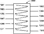
图2a说明有端口1001-1012的十二端口环行器。Figure 2a illustrates a twelve port circulator with ports 1001-1012.
图2b说明有四个端口和四个扩展接口的可扩展四端口环行器。Figure 2b illustrates an expandable four-port circulator with four ports and four expansion interfaces.
图2c说明三个可扩展四端口环行器级联在一起形成一个十二端口环行器。Figure 2c illustrates three scalable four-port circulators cascaded together to form a twelve-port circulator.
图2d说明图2c中所示可扩展四端口PM环行器中各个元件的位置和取向。Figure 2d illustrates the location and orientation of the various elements in the scalable four-port PM circulator shown in Figure 2c.
图3a(1)-图3a(3)说明在端口1引入的光信号被分割成两个光束,这两个光束重新组合之后从端口2射出。Figure 3a(1)-Figure 3a(3) illustrate that the optical signal introduced at
图3b(1)-图3b(3)说明在端口2引入的光信号被分割成两个光束,这两个光束重新组合之后从端口3射出。Figure 3b(1)-Figure 3b(3) illustrate that the optical signal introduced at
图3c(1)-图3c(3)说明在端口3引入的光信号被分割成两个光束,这两个光束重新组合之后从端口4射出。Figure 3c(1)-Figure 3c(3) illustrate that the optical signal introduced at
图3d(1)-图3d(3)说明在端口4引入的光信号被分割成两个光束,这两个光束组合之后从两个扩展接口射出。Fig. 3d(1)-Fig. 3d(3) illustrate that the optical signal introduced at the
图3e(1)-图3e(3)说明射入两个扩展接口的光束组合之后从端口1射出。Figures 3e(1)-3e(3) illustrate that beams entering two expansion ports are combined and
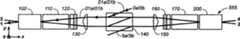
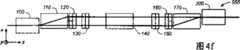
图4a-图4e分别说明图3a-图3e中光束在y-z平面上传播的光路。Figures 4a-4e respectively illustrate the optical path of the light beam propagating on the y-z plane in Figures 3a-3e.
图4f说明图4a-图4e中光束在x-z平面上传播的光路。Fig. 4f illustrates the optical path of the light beam propagating in the x-z plane in Figs. 4a-4e.
图5说明图2的三个可扩展四端口环行器级联在一起形成一个十二端口环行器。FIG. 5 illustrates that three scalable four-port circulators of FIG. 2 are cascaded together to form a twelve-port circulator.
图6和图7说明图5中十二端口环行器的其他实施方案。6 and 7 illustrate other embodiments of the twelve-port circulator of FIG. 5 .
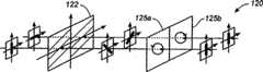
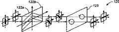
图8a和图8b说明有一个半波片和两个法拉第旋转器的非互易装置120的实施方案。Figures 8a and 8b illustrate an embodiment of a
图9a和图9b说明有两个半波片和一个法拉第旋转器的非互易装置120的实施方案。Figures 9a and 9b illustrate an embodiment of a
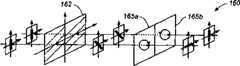
图10a和图10b说明有一个半波片和两个法拉第旋转器的非互易装置160的实施方案。Figures 10a and 10b illustrate an embodiment of a
图11a和图11b说明有两个半波片和一个法拉第旋转器的非互易装置160的实施方案。Figures 11a and 11b illustrate an embodiment of a
具体实施方式Detailed ways
本发明涉及光学技术的改进。以下的描述能使本领域的普通专业人员实现和利用本发明,而且它是在专利申请及其要求的语境下。本发明的各种改动对于专业人员是显而易见的,此处描述的一般原理可应用于其他的实施例。因此,本发明不局限于所描述的实施例,而是在最大的范围内符合此处描述的原理和特征。This invention relates to improvements in optical technology. The following description enables one of ordinary skill in the art to make and use the invention, and it is in the context of the patent application and its claims. Various modifications of the invention will be readily apparent to those skilled in the art, and the general principles described herein may be applied to other embodiments. Thus, the invention is not intended to be limited to the described embodiments but is to be accorded the widest extent consistent with the principles and features described herein.
本发明描述有特定元件和特定配置的一种可扩展四端口环行器和十二端口环行器。类似地,本发明描述的元件有特定的关系,例如,各个元件之间的距离或夹角。然而,本领域的普通专业人员容易理解,这种方法和系统可以有效地适用于有类似性质的其他元件,其他配置,和各个元件之间的其他关系。The present invention describes a scalable four-port circulator and twelve-port circulator with specific components and specific configurations. Similarly, elements described herein have specific relationships, such as distances or angles between elements. However, one of ordinary skill in the art will readily appreciate that the method and system may be effectively adapted to other elements having similar properties, other configurations, and other relationships between the various elements.
图2a表示包含十二个端口1001-1012的一种十二端口环行器。如图2a所示,射入端口1001的光信号从端口1002射出,而射入端口1002的光信号从端口1003射出。类似地,射入端口1003,1004,1005,1006,1007,1008,1009,1010,和1011的光信号分别从端口1004,1005,1006,1007,1008,1009,1010,1011,和1012射出。Figure 2a shows a twelve-port circulator comprising twelve ports 1001-1012. As shown in FIG. 2 a , an optical
利用若干种不同的方法可以构造十二端口环行器。一种可能的十二端口环行器实施方案是级联三个可扩展四端口环行器。图2b表示这个申请中描述的可扩展四端口环行器。可扩展四端口环行器555包括:四个端口1,2,3,和4,以及扩展接口0a,0b,5a,和5b。如图2b所示,在端口1射入的光信号从端口2射出,在端口2射入的光信号从端口3射出,和在端口3射入的光信号从端口4射出。此外,在扩展接口0a和0b射入的光信号合并在一起并从端口1射出,而在端口4射入的光信号被分割成两个光信号,分别从接口5a和5b射出。Twelve-port circulators can be constructed using several different methods. One possible twelve-port circulator implementation is to cascade three scalable four-port circulators. Figure 2b shows the scalable four-port circulator described in this application. The expandable four-
图2c表示三个可扩展四端口环行器555′,555和555″级联在一起,形成一个十二端口环行器1000。环行器555′的接口5a′和5b′分别耦合到环行器555的接口0a和0b,而环行器555的接口5a和5b分别耦合到环行器555″的接口0a″和0b″。四端口环行器555′的端口1′,2′,3′,和4′分别相当于十二端口环行器1000的端口1001,1002,1003,和1004;四端口环行器555的端口1,2,3,和4分别相当于十二端口环行器1000的端口1005,1006,1007,和1008;而四端口环行器555″的端口1″,2″,3″,和4″分别相当于十二端口环行器1000的端口1009,1010,1011,和1012。Fig. 2c shows that three expandable four-
图2d表示可扩展四端口环行器555的实施方案。环行器555包括:双光纤准直器100,双折射晶体110,非互易装置120,光楔130,双折射晶体140,光楔150,非互易装置160,双折射晶体170,和双光纤准直器200。双光纤准直器100和200中的每个准直器可以耦合到两个光纤(未画出)。环行器555包括:四个端口1,2,3,和4,以及扩展接口0a,0b,5a,和5b。准直器100中两个联结器分别构成端口1和3,而准直器200中两个联结器分别构成端口2和4。双折射晶体140表面142上两个区域构成扩展接口0a和0b,而双折射晶体140表面144上两个区域构成扩展接口5a和5b。FIG. 2d shows an implementation of a scalable four-
光束可以射入可扩展四端口环行器555中给定元件的四个区域之一。这四个区域标记为象限I,II,III,和IV,如图2d所示。在这个图中还画出x方向,y方向和z方向。正z方向是在双光纤准直器100中引入光束的传播方向。A light beam can be launched into one of four regions of a given element in expandable four-
图3a(1),3a(2)和3a(3)说明,在端口1引入的光信号被分割成光束12a和12b;光束12a和12b重新组合并从端口2射出。图3a(1)是透视图,图3a(2)是y-z平面上的平面视图,而图3a(3)是x-z平面上的平面视图。3a(1), 3a(2) and 3a(3) illustrate that an optical signal introduced at
在端口1引入的光信号在双折射晶体110中被分割成具有y偏振的光束12a和具有x偏振的光束12b。光束12a不发生偏转,并从双折射晶体110的象限II射出。光束12b沿正x方向发生偏转,并从双折射晶体110的象限I射出。在从双折射晶体110射出之后,光束12a和12b沿正z方向和略微正y方向传播。An optical signal introduced at
光束12a以y偏振射入非互易装置120的象限II,并以x偏振从象限II射出。在传播通过光楔130的象限II之后,光束12a发生偏转,基本上沿正z方向传播。然后,光束12a传播通过双折射晶体140的象限II,而没有发生偏转。在传播通过光楔150的象限II之后,光束12a发生偏转,沿正z方向和略微负y方向传播。此后,光束12a以x偏振射入非互易装置160的象限II,以x偏振从象限II射出。最后,光束12a射入双折射晶体170的象限II,在沿正x方向被该晶体偏转,并以x偏振射入双光纤准直器200。
光束12b以x偏振射入非互易装置120的象限I,并以x偏振从象限I射出。在传播通过光楔130的象限I之后,光束12b发生偏转,基本上沿正z方向传播。然后,光束12b传播通过双折射晶体140的象限I,不发生偏转。在传播通过光楔150的象限I之后,光束12b发生偏转,沿正z方向和略微负y方向传播。此后,光束12b以x偏振射入非互易装置160的象限I,并以y偏振从象限I射出。最后,光束12b传播通过双折射晶体170的象限I,不被该晶体偏转,并以y偏振射入双光纤准直器200。
光束12a和12b分别以x偏振和y偏振射入准直器200,在准直器200中组合,并从端口2射出。
图3b(1),3b(2)和3b(3)说明,在端口2引入的光信号被分割成光束23a和23b;光束23a和23b重新组合并从端口3射出。图3b(1)是透视图,图3b(2)是y-z平面上的平面视图,而图3b(3)是x-z平面上的平面视图。Figures 3b(1), 3b(2) and 3b(3) illustrate that the optical signal introduced at
在端口2引入的光信号被分割成具有x偏振的光束23a和具有y偏振的光束23b。光束23a沿负x方向发生偏转,并从双折射晶体170的象限II射出。光束23b不发生偏转,并从双折射晶体170的象限I射出。在从双折射晶体170射出之后,光束23a和23b沿负z方向和略微正y方向传播。The optical signal introduced at
光束23a以x偏振射入非互易装置160的象限II,并以y偏振从象限II射出。在传播通过光楔150的象限II之后,光束23a发生偏转,基本上沿负z方向传播。然后,光束23a射入双折射晶体140的象限II,沿负y方向发生偏转,并从双折射晶体140的象限III射出。在传播通过光楔130的象限III之后,光束23a发生偏转,沿负z方向和略微正y方向传播。此后,光束23a以y偏振射入非互易装置120的象限III,并以y偏振从象限III射出。最后,光束23a传播通过双折射晶体110的象限III,不发生偏转,并以y偏振射入双光纤准直器100。
光束23b以y偏振射入非互易装置160的象限I,并以y偏振从象限I射出。在传播通过光楔150的象限I之后,光束23b发生偏转,基本上沿负z方向传播。然后,光束23b射入双折射晶体140的象限I,沿负y方向发生偏转,并从双折射晶体140的象限IV射出。在传播通过光楔150的象限IV之后,光束23b发生偏转,沿负z方向但倾斜于正y方向传播。此后,光束23b以y偏振射入非互易装置120的象限IV,并以x偏振从象限IV射出。最后,光束23b射入双折射晶体110的象限IV,沿负x方向发生偏转,并以x偏振射入双光纤准直器100。
光束23a和23b分别以y偏振和x偏振射入双光纤准直器200,在准直器100中组合,并从端口3射出。
图3c(1),3c(2)和3c(3)说明,在端口3引入的光信号被分割成光束34a和34b;光束34a和34b重新组合,并从端口4射出。图3c(1)是透视图,图3c(2)是y-z平面上的平面视图,而图3c(3)是x-z平面上的平面视图。Figures 3c(1), 3c(2) and 3c(3) illustrate that the optical signal introduced at
在端口3引入的光信号被双折射晶体110分割成具有y偏振的光束34a和具有x偏振的光束34b。光束34a不发生偏转,并从双折射晶体110的象限III射出。光束34b沿正x方向发生偏转,并从双折射晶体110的象限IV射出。在从双折射晶体110射出之后,光束34a和34b沿正z方向和略微负y方向传播。The optical signal introduced at
光束34a以y偏振射入非互易装置120的象限III,并以x偏振从象限III射出。在传播通过光楔130的象限III之后,光束34a发生偏转,基本上沿正z方向传播。然后,光束34a传播通过双折射晶体140的象限III,不发生偏转。在传播通过光楔150的象限III之后,光束34a发生偏转,沿正z方向和略微正y方向传播。此后,光束34a以x偏振射入非互易装置160的象限III,并以x偏振从象限III射出。最后,光束34a射入双折射晶体170的象限II,沿正x方向发生偏转,并以x偏振射入双光纤准直器200。
光束34b以x偏振射入非互易装置120的象限IV,并以x偏振从象限I射出。在传播通过光楔130的象限IV之后,光束34b发生偏转,基本上沿正z方向传播。然后,光束34b传播通过双折射晶体140的象限IV,不发生偏转。在传播通过光楔150的象限IV之后,光束34b发生偏转,沿正z方向和略微正y方向传播。此后,光束34b以x偏振射入非互易装置160的象限IV,并以y偏振从象限IV射出。最后,光束34b传播通过双折射晶体170的象限IV,并以y偏振射入双光纤准直器200。
光束34a和34b分别以x偏振和y偏振射入准直器200,在准直器200中组合,并从端口4射出。
图3d(1),3d(2)和3d(3)说明,在端口4引入的光信号被分割成光束45a和45b;光束45a和45b分别从扩展接口5a和5b射出。图3d(1)是透视图,图3d(2)是y-z平面上的平面视图,而图3d(3)是x-z平面上的平面视图。Figures 3d(1), 3d(2) and 3d(3) illustrate that the optical signal introduced at
在双光纤准直器200的端口4引入的光信号被双折射晶体170分割成具有x偏振的光束45a和具有y偏振的光束45b。光束45a沿负x方向发生偏转,并从双折射晶体170的象限III射出。光束45b不发生偏转,并从双折射晶体170的象限IV射出。在从双折射晶体170射出之后,光束45a和45b沿负z方向和略微y方向传播。The optical signal introduced at
光束45a以x偏振射入非互易装置160的象限III,并以y偏振从象限III射出。在传播通过光楔150的象限III之后,光束45a发生偏转,基本上沿负z方向传播。然后,光束45a射入双折射晶体140的象限III,沿负y方向发生偏转,并以y偏振从双折射晶体140的表面144上扩展接口5a射出。
光束45b以y偏振射入非互易装置160的象限IV,并以y偏振从象限IV射出。在传播通过光楔150的象限IV之后,光束45b发生偏转,基本上沿负z方向传播。然后,光束45b射入双折射晶体140的象限IV,沿负y方向发生偏转,并以y偏振从双折射晶体140表面144上的扩展接口5b射出。
图3e(1),3e(2)和3e(3)说明,光束45a和45b分别射入可扩展四端口环行器555的扩展接口0a和0b,组合之后从端口1射出。图3e(1)是透视图,图3e(2)是y-z平面上的平面视图,而图3e(3)是x-z平面上的平面视图。3e(1), 3e(2) and 3e(3) illustrate that the
光束01a以y偏振射入双折射晶体140表面142上的扩展接口0a,并沿负z方向从双折射晶体140的象限II射出。在传播通过光楔130的象限II之后,光束01a发生偏转,沿负z方向但倾斜于负y方向传播。此后,光束01a以y偏振射入非互易装置120的象限II,并以y偏振从象限II射出。最后,光束01a传播通过双折射晶体110的象限I,不发生偏转,并以y偏振射入双光纤准直器200。
光束01b以y偏振射入双折射晶体140表面142上的扩展接口0b,并沿负z方向从双折射晶体140的象限I射出。在传播通过光楔130的象限I之后,光束01b发生偏转,沿负z方向和略微负y方向传播。此后,光束01b以y偏振射入非互易装置160的象限I,并以x偏振从象限I射出。最后,光束01b射入双折射晶体110的象限I,沿负x方向发生偏转,并以x偏振射入双光纤准直器100。
光束01a和01b分别以y偏振和x偏振射入准直器200,在准直器100中组合,并从端口1射出。
y-z平面上所示的图4a,4b,4c,4d,和4e分别表示图3a(3),3b(3),3c(3),3d(3),和3e(3)中光束的传播光路。图4f表示x-z平面上的光路。图4a-4e中的每个图表示在端口1,2,3,和4以及扩展接口0a和0b引入光束的传播光路。在每个图中,光束传播的实际光路是用带箭头的线条表示。Figures 4a, 4b, 4c, 4d, and 4e shown on the y-z plane represent the propagation paths of light beams in Figures 3a(3), 3b(3), 3c(3), 3d(3), and 3e(3) respectively . Figure 4f shows the light path in the x-z plane. Each of Figures 4a-4e represents the propagation path of light beams introduced at
图4a表示在端口1引入的光信号被分割成光束12a和12b,光束12a和12b重新组合之后从端口2射出。图4b表示在端口2引入的光信号被分割成光束23a和23b,光束23a和23b重新组合之后从端口3射出。图4c表示在端口3引入的光信号被分割成光束34a和34b,光束34a和34b重新组合之后从端口2射出。图4d表示在端口4引入的光信号被分割成光束45a和45b,光束45a和45b分别从扩展接口5a和5b射出。图4e表示光束01a和01b分别射入扩展接口0a和0b,组合之后从端口1射出。FIG. 4a shows that the optical signal introduced at
图5表示三个可扩展四端口环行器555′,555,和555″级联在一起,形成一个十二端口环行器1000。通过环行器555′表面144′与环行器555表面142的直接接触,环行器555′的扩展接口5a′和5b′分别耦合到环行器555的扩展接口0a和0b。在一种实施方案中,通过环行器555表面144与环行器555″表面142″的直接接触,环行器555的扩展接口5a和5b分别耦合到环行器555″的扩展接口0a″和0b″。环行器555′表面142′上的扩展接口0a′和0b′以及环行器555″表面144″上的扩展接口5a″和5b″是不使用的,所以不需要进行耦合。如图所示,可以利用单个双折射晶体410代替双折射晶体140′,140,和144″。Figure 5 shows three expandable four-
图6表示另一种实施方案的十二端口环行器1000。十二端口环行器1000包括四对反射器:反射器311和312,反射器321和322,反射器511和512,和反射器521和522。利用反射器311和312,使双光纤准直器100′,双折射晶体110′,非互易装置120′,和光楔130′中传播的光路沿正y方向一起移位。利用反射器321和322,使光楔150,非互易装置160,双折射晶体170,和双光纤准直器200中传播的光路沿正y方向一起移位。利用反射器511和512,使双光纤准直器100″,双折射晶体110″,非互易装置120″,和光楔130″中传播的光路沿负y方向一起移位。最后,利用反射器521和522,使光楔150″,非互易装置160″,双折射晶体170″,和双光纤准直器200″中传播的光路沿负y方向一起移位。FIG. 6 shows a twelve-
另一种实施方案的十二端口环行器1000还可以利用一对,两对,或三对反射器,以代替四对反射器。此外,可以利用单个反射器代替一对反射器。例如,若仅利用反射器312和去掉反射器311,则可以把双光纤准直器100′,双折射晶体110′,非互易装置120′,和光楔130′的取向一起旋转90度,使得在双光纤准直器100引入的光束传播方向最初是在负y方向。在十二端口环行器1000的实施方案中,一般可以把反射器,反射器对,或光楔称之为光路调节元件。Alternative embodiments of the twelve-
图7表示另一种实施方案的十二端口环行器1000,至少包括一个公用的元件以代替图5中的一组单个元件。例如,可以用图7中的公用双折射晶体110代替图5中的双折射晶体110′,110,和110″。类似地,可以用公用的双折射晶体710代替双折射晶体170′,170,和170″。可以用公用的非互易装置210代替非互易装置120′,120,和120″。可以用公用的非互易装置610代替非互易装置160′,160,和160″。FIG. 7 shows another embodiment of a twelve-
如上所述,可扩展四端口环行器555中每个元件的功能取决于光束射入的方向和象限。以下描述图2的可扩展四端口环行器555中每个元件的结构。当光束沿正z方向传播时,参照图3a和3c描述每个元件的功能。同样地,当光束沿负z方向传播时,参照图3b,3d,和3e描述每个元件的功能。As mentioned above, the function of each element in the expandable four-
双折射晶体110的结构和取向是为了完成以下的功能:(1)以y偏振沿正z方向传播通过双折射晶体120的光不发生偏转,而以y偏振沿正x方向传播的光发生偏转;(2)以y偏振沿负z方向传播通过双折射晶体120的光不发生偏转,而以x偏振沿负x方向传播的光发生偏转。因此,按照它们各自的偏振方向,双折射晶体120分割或合并光束。双折射晶体120中0光线的偏振方向是在y方向。The structure and orientation of the
非互易装置120的结构是为了完成以下的功能:(1)以x偏振沿正z方向传播通过非互易装置120并通过象限I或IV射入装置120的光保持x偏振,而以y偏振通过象限II或III射入装置120的光变成具有x偏振的光;(2)以y偏振沿负z方向传播通过非互易装置120并通过象限I或IV射入装置120的光变成具有x偏振的光,而以y偏振通过象限II或III射入装置120的光保持y偏振。The structure of the
双折射晶体140的结构和取向是为了完成以下的功能:(1)以x偏振沿正z方向传播通过双折射晶体140的光不发生偏转:(2)以y偏振沿负z方向传播通过双折射晶体140的光沿负y方向发生偏转。双折射晶体140中O光线的偏振方向是在x方向。The structure and orientation of the
非互易装置160的结构是为了完成以下的功能:(1)以x偏振沿正z方向传播通过非互易装置160并通过象限I或IV射入装置160的光变成具有y偏振的光,而以x偏振通过象限II或III射入装置160的光保持x偏振;(2)以y偏振沿负z方向传播通过互易装置160并通过象限I或IV射入装置160的光保持y偏振,而以x偏振通过象限II或III射入装置160的光变成具有y偏振的光。The structure of the
可以利用若干种不同的方法实现非互易装置120。如图8a和8b所示,非互易装置120包括:半波片122和法拉第旋转器125a和125b。在一种实施方案中,半波片122的光轴是在从正x方向旋转22.5度的矢量方向。当光束传播通过法拉第旋转器125a时,在正z或负z方向上,光束的偏振方向相对于正z轴旋转+45度。当光束传播通过法拉第旋转器125b时,在正z或负z方向上,光束的偏振方向相对于正z轴旋转-45度。The non-reciprocal means 120 can be implemented in several different ways. As shown in Figures 8a and 8b, the
如图8a所示,在沿z方向传播通过半波片122之后,具有x偏振的光束变成具有x+y偏振的光束,而具有y偏振的光束变成具有x-y偏振的光束。在传播通过法拉第旋转器125a之后,具有x-y偏振的光束旋转+45度,变成具有x偏振的光束。同样地,在传播通过法拉第旋转器125b之后,具有x+y偏振的光束旋转-45度,变成具有x偏振的光束。As shown in Fig. 8a, after propagating through the half-
如图8b所示,在沿负z方向传播通过法拉第旋转器125a之后,具有y偏振的光束旋转+45度,变成具有x-y偏振的光束。在传播通过半波片122之后,具有x-y偏振的光束变成具有y偏振的光束。在沿负z方向传播通过法拉第旋转器125b之后,具有y偏振的光束旋转-45度,变成具有x+y偏振的光束。在传播通过半波片122之后,具有x+y偏振的光束变成具有x偏振的光束。As shown in Figure 8b, after propagating through the
在图8a和8b的实施方案中,当半波片122的位置与法拉第旋转器125a和125b的位置交换之后,非互易装置120的功能保持不变。还可以给半波片122选取其他的光轴以及给法拉第旋转器125a和125b选取其他的旋转方向。In the embodiment of Figures 8a and 8b, the function of the
如图9a和9b所示,非互易装置120包括:半波片122a和122b以及法拉第旋转器125。半波片122a的光轴是在从正x方向旋转+22.5度的矢量方向。半波片122b的光轴是在从正x方向旋转-22.5度的矢量方向。当光束传播通过法拉第旋转器125之后,在正z或负z方向上,光束的偏振旋转+45度。As shown in FIGS. 9 a and 9 b , the
如图9a所示,在沿正z方向传播通过半波片122a之后,具有y偏振的光束变成具有x-y偏振的光束。同样地,在沿正z方向传播通过半波片122b之后,具有x偏振的光束变成具有x-y偏振的光束。在传播通过法拉第旋转器125之后,具有x-y偏振的光束旋转+45度,变成具有x偏振的光束。As shown in Fig. 9a, after propagating through the half-
如图9b所示,在沿负z方向传播通过法拉第旋转器125之后,具有y偏振的光束旋转+45度,变成具有x-y偏振的光束。在传播通过半波片122a之后,具有x-y偏振的光束变成具有y偏振的光束。在传播通过半波片122b之后,具有x-y偏振的光束变成具有x偏振的光束。As shown in Figure 9b, after propagating through the
在图9a和9b的实施方案中,当半波片122a和122b的位置与法拉第旋转器125的位置交换交换之后,非互易装置120的功能保持不变。还可以给半波片122a和122b选取其他的光轴以及给法拉第旋转器125选取其他的旋转方向。In the embodiment of FIGS. 9 a and 9 b , the function of the
类似于非互易装置120,利用一个半波片与两个法拉第旋转器的组合,或利用两个半波片与一个法拉第旋转器的组合,可以构造公用的非互易装置210。Similar to the
利用若干种不同的方法可以实现非互易装置160。如图10a和10b所示,非互易装置160包括:半波片162以及法拉第旋转器165a和165b。半波片162的光轴是在从正x方向旋转22.5度的矢量方向。当光束传播通过法拉第旋转器165a之后,在正z或负z方向上,光束的偏振方向旋转-45度。当光束传播通过法拉第旋转器165b之后,在正z或负z方向上,光束的偏振方向旋转+45度。The non-reciprocal means 160 can be implemented using several different methods. As shown in Figures 10a and 10b, the
如图10a所示,在沿正z方向传播通过半波片162之后,具有x偏振的光束变成具有x+y偏振的光束。在传播通过法拉第旋转器165a之后,具有x+y偏振的光束旋转-45度,变成具有x偏振的光束。在传播通过法拉第旋转器165b之后,具有x+y偏振的光束旋转+45度,变成具有y偏振的光束。As shown in Figure 10a, after propagating through the
如图10b所示,在沿负z方向传播通过法拉第旋转器165a之后,具有x偏振的光束旋转-45度,变成具有x-y偏振的光束。同样地,在沿负z方向传播通过法拉第旋转器165b之后,具有y偏振的光束旋转+45度,变成具有x-y偏振的光束。在传播通过半波片162之后,具有x-y偏振的光束变成具有y偏振的光束。As shown in Figure 10b, after propagating through the
在图10a和10b的实施方案中,当半波片162的位置与法拉第旋转器165a和165b的位置交换之后,非互易装置160的功能保持不变。还可以给半波片162选取其他的光轴以及给法拉第旋转器165a和165b选取其他的旋转方向。In the embodiment of Figures 10a and 10b, the function of the
如图11a和11b所示,非互易装置160包括:半波片162a和162b以及法拉第旋转器165。半波片162a的光轴是在从正x方向旋转-22.5度的矢量方向。半波片162b的光轴是在从正x方向旋转+22.5度的矢量方向。当光束传播通过法拉第旋转器165之后,在正z或负z方向上,光束的偏振方向旋转+45度。As shown in FIGS. 11 a and 11 b , the
如图11a所示,在沿正z方向传播通过半波片162a之后,具有x偏振的光束变成具有x-y偏振的光束。在沿正z方向传播通过半波片162b之后,具有x偏振的光束变成具有x+y偏振的光束。在传播通过法拉第旋转器165和旋转+45度之后,具有x-y偏振的光束变成具有x偏振的光束,而具有x+y偏振的光束变成具有y偏振的光束。As shown in Fig. 11a, after propagating through the half-
如图11b所示,在沿负z方向传播通过法拉第旋转器165和旋转+45度之后,具有x偏振的光束变成具有x+y偏振的光束,而具有y偏振的光束变成具有x-y偏振的光束。在传播通过半波片162a之后,具有x+y偏振的光束变成具有y偏振的光束。同样地,在传播通过半波片162b之后,具有x-y偏振的光束变成具有y偏振的光束。As shown in Figure 11b, after propagating through the
在图11a和11b的实施方案中,半波片162a和162b的位置可以与法拉第旋转器165的位置交换,而非互易装置160的功能保持不变。还可以给半波片162a和162b选取其他的光轴和给法拉第旋转器165选取其他的旋转方向。In the embodiment of Figures 11a and 11b, the position of the half-
类似于非互易装置160,利用一个半波片与两个法拉第旋转器的组合,或利用两个半波片与一个法拉第旋转器的组合,可以构造公用的非互易装置610。Similar to the
我们公开一种提供可扩展四端口环行器的方法和系统,这些四端口环行器可以级联或组合成一个十二端口环行器。虽然本发明的描述是参照所展示的实施例,本领域的普通专业人员容易地理解,可以对这些实施例作各种变动,这种变动都是在本发明的精神和范围内。例如,两个可扩展四端口环行器可以级联或组合成一个八端口环行器,四个可扩展环行器可以级联或组合成一个八端口环行器。一般地说,整数N个可扩展四端口环行器可以级联或组合成4N端口环行器。因此,在不偏离所附权利要求书精神和范围的条件下,本领域的普通专业人员可以进行各种改动。We disclose a method and system for providing scalable four-port circulators that can be cascaded or combined into a twelve-port circulator. Although the invention has been described with reference to the illustrated embodiments, those of ordinary skill in the art will readily appreciate that various changes may be made to these embodiments while remaining within the spirit and scope of the invention. For example, two scalable four-port circulators can be cascaded or combined to form an eight-port circulator, and four scalable circulators can be cascaded or combined to form an eight-port circulator. Generally speaking, an integer number of N scalable four-port circulators can be cascaded or combined into a 4N-port circulator. Accordingly, various modifications may be made by those of ordinary skill in the art without departing from the spirit and scope of the appended claims.
Claims (11)
Translated fromChineseApplications Claiming Priority (2)
| Application Number | Priority Date | Filing Date | Title |
|---|---|---|---|
| US10/075,432US6751366B2 (en) | 2002-02-12 | 2002-02-12 | Multi-port circulator |
| US10/075,432 | 2002-02-12 |
Related Parent Applications (1)
| Application Number | Title | Priority Date | Filing Date |
|---|---|---|---|
| CNB031038166ADivisionCN1242291C (en) | 2002-02-12 | 2003-02-12 | Multi-port circulator |
Publications (2)
| Publication Number | Publication Date |
|---|---|
| CN1800894Atrue CN1800894A (en) | 2006-07-12 |
| CN100356210C CN100356210C (en) | 2007-12-19 |
Family
ID=27660081
Family Applications (2)
| Application Number | Title | Priority Date | Filing Date |
|---|---|---|---|
| CNB2005101296117AExpired - Fee RelatedCN100356210C (en) | 2002-02-12 | 2003-02-12 | Multi-port circulator |
| CNB031038166AExpired - Fee RelatedCN1242291C (en) | 2002-02-12 | 2003-02-12 | Multi-port circulator |
Family Applications After (1)
| Application Number | Title | Priority Date | Filing Date |
|---|---|---|---|
| CNB031038166AExpired - Fee RelatedCN1242291C (en) | 2002-02-12 | 2003-02-12 | Multi-port circulator |
Country Status (2)
| Country | Link |
|---|---|
| US (2) | US6751366B2 (en) |
| CN (2) | CN100356210C (en) |
Families Citing this family (5)
| Publication number | Priority date | Publication date | Assignee | Title |
|---|---|---|---|---|
| US7286730B2 (en)* | 2006-03-15 | 2007-10-23 | Avanex Corporation | Optical switch having angle tuning elements and multiple-fiber collimators |
| TWI372270B (en)* | 2009-05-04 | 2012-09-11 | Ind Tech Res Inst | Optical switch and communication system of optical signal |
| CN102393198B (en)* | 2011-10-20 | 2015-04-08 | 武汉虹拓新技术有限责任公司 | Optical gyroscope |
| CN102854564B (en)* | 2012-09-11 | 2014-04-09 | 华中科技大学 | Four-port optical circulator with symmetric structure |
| FR3060248B1 (en)* | 2016-12-09 | 2019-03-15 | Safran Electrical & Power | OPTICAL RING OPERATED COMMUNICATION NETWORK FOR AIRCRAFT |
Family Cites Families (11)
| Publication number | Priority date | Publication date | Assignee | Title |
|---|---|---|---|---|
| JP2775547B2 (en)* | 1992-02-17 | 1998-07-16 | 秩父小野田株式会社 | Optical isolator |
| WO1995016216A1 (en)* | 1993-12-10 | 1995-06-15 | Jds Fitel Inc. | Optical non-reciprocal devices |
| EP0799432A4 (en)* | 1994-12-21 | 1999-03-24 | E Tek Dynamics Inc | Integrable fiberoptic coupler and resulting devices and systems |
| CA2148317C (en)* | 1995-05-01 | 1998-05-05 | Yihao Cheng | Optical circulator |
| US5689593A (en)* | 1995-10-13 | 1997-11-18 | E-Tek Dynamics, Inc. | Compact fiberoptic circulator with low polarization mode dispersion |
| US5682446A (en)* | 1995-10-13 | 1997-10-28 | E-Tek Dynamics, Inc. | Polarization mode dispersion-free circulator |
| US6026202A (en)* | 1997-02-25 | 2000-02-15 | Hewlett-Packard Company | Compact, low crosstalk, three-port optical circulator |
| US5909310A (en)* | 1997-12-08 | 1999-06-01 | U.S.A Kaifa Technology, Inc. | Optical circulator |
| US5930039A (en)* | 1997-12-08 | 1999-07-27 | U.S.A Kaifa Technology, Inc. | Optical circulator |
| US6154581A (en)* | 1998-10-27 | 2000-11-28 | Adc Telecommunications, Inc. | Multiple port, fiber optic circulator |
| US6246807B1 (en)* | 1999-04-06 | 2001-06-12 | Adc Telecommunications, Inc. | Optical circulator |
- 2002
- 2002-02-12USUS10/075,432patent/US6751366B2/ennot_activeExpired - Lifetime
- 2003
- 2003-02-12CNCNB2005101296117Apatent/CN100356210C/ennot_activeExpired - Fee Related
- 2003-02-12CNCNB031038166Apatent/CN1242291C/ennot_activeExpired - Fee Related
- 2004
- 2004-06-01USUS10/859,329patent/US6888971B2/ennot_activeExpired - Fee Related
Also Published As
| Publication number | Publication date |
|---|---|
| US20030152306A1 (en) | 2003-08-14 |
| CN100356210C (en) | 2007-12-19 |
| US6888971B2 (en) | 2005-05-03 |
| US6751366B2 (en) | 2004-06-15 |
| CN1438517A (en) | 2003-08-27 |
| US20040218846A1 (en) | 2004-11-04 |
| CN1242291C (en) | 2006-02-15 |
Similar Documents
| Publication | Publication Date | Title |
|---|---|---|
| CN1195238C (en) | Beam splitter and beam combiner with isolated polarized beam | |
| CN1251175A (en) | Optical circulator | |
| CN1239552A (en) | Optical isolator | |
| CN1352756A (en) | Multiple port fiber optical circulator | |
| JP2000028966A (en) | Optical signal transmission method and optical device | |
| CN1769936A (en) | Depolarizer | |
| CN110531458A (en) | A kind of super surface of achievable nonreciprocity function | |
| CN100406959C (en) | Light-gathering device | |
| JP2000019456A5 (en) | ||
| CN1800894A (en) | Multi-port circulator | |
| CN1278156C (en) | Optical splitter | |
| CN1530694A (en) | Reflective Variable Attenuator and Shunt Monitor | |
| CN1203350C (en) | Method and apparatus for optical swhich-over | |
| CN1303020A (en) | Light circulator | |
| CN1224852C (en) | Four-port polarization holding circulator | |
| JPH0668585B2 (en) | Optical isolator | |
| CN1195999C (en) | Multi-stage light isolator | |
| JP4287522B2 (en) | Split optical element and manufacturing method thereof | |
| CN2648707Y (en) | Closed circuit circulator | |
| CN2550777Y (en) | Multi-path light isolator | |
| CN1549002A (en) | Miniature 2X2 Magneto-optical Switch | |
| CN1159603C (en) | Optical circulator with three ports | |
| CN1450372A (en) | Optical isolator | |
| CN1224858C (en) | Three-port polarisation-retaining circulator with isolation function | |
| CN1190676C (en) | Optical circulator and its polarized light circulating device |
Legal Events
| Date | Code | Title | Description |
|---|---|---|---|
| C06 | Publication | ||
| PB01 | Publication | ||
| C10 | Entry into substantive examination | ||
| SE01 | Entry into force of request for substantive examination | ||
| C14 | Grant of patent or utility model | ||
| GR01 | Patent grant | ||
| CF01 | Termination of patent right due to non-payment of annual fee | ||
| CF01 | Termination of patent right due to non-payment of annual fee | Granted publication date:20071219 Termination date:20200212 |