CN1790816A - Output Components and Connectors - Google Patents
Output Components and ConnectorsDownload PDFInfo
- Publication number
- CN1790816A CN1790816ACNA2005101251506ACN200510125150ACN1790816ACN 1790816 ACN1790816 ACN 1790816ACN A2005101251506 ACNA2005101251506 ACN A2005101251506ACN 200510125150 ACN200510125150 ACN 200510125150ACN 1790816 ACN1790816 ACN 1790816A
- Authority
- CN
- China
- Prior art keywords
- conductor
- flat wire
- flat
- wire
- connector
- Prior art date
- Legal status (The legal status is an assumption and is not a legal conclusion. Google has not performed a legal analysis and makes no representation as to the accuracy of the status listed.)
- Granted
Links
- 239000004020conductorSubstances0.000claimsabstractdescription139
- RYGMFSIKBFXOCR-UHFFFAOYSA-NCopperChemical compound[Cu]RYGMFSIKBFXOCR-UHFFFAOYSA-N0.000claimsabstractdescription59
- 239000010949copperSubstances0.000claimsabstractdescription59
- 229910052802copperInorganic materials0.000claimsabstractdescription59
- 230000008878couplingEffects0.000claims2
- 238000010168coupling processMethods0.000claims2
- 238000005859coupling reactionMethods0.000claims2
- 229910000906BronzeInorganic materials0.000claims1
- 239000010974bronzeSubstances0.000claims1
- KUNSUQLRTQLHQQ-UHFFFAOYSA-Ncopper tinChemical compound[Cu].[Sn]KUNSUQLRTQLHQQ-UHFFFAOYSA-N0.000claims1
- 230000001070adhesive effectEffects0.000abstractdescription22
- 239000000853adhesiveSubstances0.000abstractdescription21
- 239000000463materialSubstances0.000abstractdescription20
- 239000010410layerSubstances0.000description64
- 238000009413insulationMethods0.000description15
- 238000010586diagramMethods0.000description9
- 239000012790adhesive layerSubstances0.000description8
- 238000001514detection methodMethods0.000description8
- 238000009434installationMethods0.000description7
- 239000011810insulating materialSubstances0.000description6
- 230000007935neutral effectEffects0.000description6
- 230000006378damageEffects0.000description4
- 239000012528membraneSubstances0.000description4
- 238000000034methodMethods0.000description4
- 239000002390adhesive tapeSubstances0.000description3
- 230000009977dual effectEffects0.000description3
- 238000009429electrical wiringMethods0.000description3
- 229920006267polyester filmPolymers0.000description3
- 229920002799BoPETPolymers0.000description2
- JOYRKODLDBILNP-UHFFFAOYSA-NEthyl urethaneChemical compoundCCOC(N)=OJOYRKODLDBILNP-UHFFFAOYSA-N0.000description2
- 239000005041Mylar™Substances0.000description2
- 239000004809TeflonSubstances0.000description2
- 229920006362Teflon®Polymers0.000description2
- 208000027418Wounds and injuryDiseases0.000description2
- 238000007792additionMethods0.000description2
- 230000000712assemblyEffects0.000description2
- 238000000429assemblyMethods0.000description2
- 238000005520cutting processMethods0.000description2
- 208000014674injuryDiseases0.000description2
- 239000007788liquidSubstances0.000description2
- 238000012986modificationMethods0.000description2
- 230000004048modificationEffects0.000description2
- -13M 9500PC)Substances0.000description1
- 238000005299abrasionMethods0.000description1
- XAGFODPZIPBFFR-UHFFFAOYSA-NaluminiumChemical compound[Al]XAGFODPZIPBFFR-UHFFFAOYSA-N0.000description1
- 229910052782aluminiumInorganic materials0.000description1
- 238000005452bendingMethods0.000description1
- 230000005540biological transmissionEffects0.000description1
- 239000007767bonding agentSubstances0.000description1
- 238000006243chemical reactionMethods0.000description1
- 238000004891communicationMethods0.000description1
- 238000010276constructionMethods0.000description1
- 230000008602contractionEffects0.000description1
- 238000005336crackingMethods0.000description1
- 230000005611electricityEffects0.000description1
- 229910052736halogenInorganic materials0.000description1
- 150000002367halogensChemical class0.000description1
- 230000002045lasting effectEffects0.000description1
- 238000003754machiningMethods0.000description1
- 239000011140metalized polyesterSubstances0.000description1
- 239000000203mixtureSubstances0.000description1
- 235000012149noodlesNutrition0.000description1
- 239000003973paintSubstances0.000description1
- 238000010422paintingMethods0.000description1
- 230000035515penetrationEffects0.000description1
- 238000007790scrapingMethods0.000description1
- 238000007789sealingMethods0.000description1
- 238000003860storageMethods0.000description1
- 239000000126substanceSubstances0.000description1
Images


Classifications
- H—ELECTRICITY
- H02—GENERATION; CONVERSION OR DISTRIBUTION OF ELECTRIC POWER
- H02G—INSTALLATION OF ELECTRIC CABLES OR LINES, OR OF COMBINED OPTICAL AND ELECTRIC CABLES OR LINES
- H02G3/00—Installations of electric cables or lines or protective tubing therefor in or on buildings, equivalent structures or vehicles
- H02G3/26—Installations of cables, lines, or separate protective tubing therefor directly on or in walls, ceilings, or floors
- H02G3/266—Mounting by adhesive material
- H—ELECTRICITY
- H01—ELECTRIC ELEMENTS
- H01B—CABLES; CONDUCTORS; INSULATORS; SELECTION OF MATERIALS FOR THEIR CONDUCTIVE, INSULATING OR DIELECTRIC PROPERTIES
- H01B7/00—Insulated conductors or cables characterised by their form
- H01B7/0009—Details relating to the conductive cores
- H01B7/0018—Strip or foil conductors
- H—ELECTRICITY
- H01—ELECTRIC ELEMENTS
- H01B—CABLES; CONDUCTORS; INSULATORS; SELECTION OF MATERIALS FOR THEIR CONDUCTIVE, INSULATING OR DIELECTRIC PROPERTIES
- H01B7/00—Insulated conductors or cables characterised by their form
- H01B7/08—Flat or ribbon cables
- H—ELECTRICITY
- H01—ELECTRIC ELEMENTS
- H01R—ELECTRICALLY-CONDUCTIVE CONNECTIONS; STRUCTURAL ASSOCIATIONS OF A PLURALITY OF MUTUALLY-INSULATED ELECTRICAL CONNECTING ELEMENTS; COUPLING DEVICES; CURRENT COLLECTORS
- H01R25/00—Coupling parts adapted for simultaneous co-operation with two or more identical counterparts, e.g. for distributing energy to two or more circuits
- H01R25/16—Rails or bus-bars provided with a plurality of discrete connecting locations for counterparts
- H—ELECTRICITY
- H02—GENERATION; CONVERSION OR DISTRIBUTION OF ELECTRIC POWER
- H02B—BOARDS, SUBSTATIONS OR SWITCHING ARRANGEMENTS FOR THE SUPPLY OR DISTRIBUTION OF ELECTRIC POWER
- H02B1/00—Frameworks, boards, panels, desks, casings; Details of substations or switching arrangements
- H02B1/20—Bus-bar or other wiring layouts, e.g. in cubicles, in switchyards
- H—ELECTRICITY
- H02—GENERATION; CONVERSION OR DISTRIBUTION OF ELECTRIC POWER
- H02G—INSTALLATION OF ELECTRIC CABLES OR LINES, OR OF COMBINED OPTICAL AND ELECTRIC CABLES OR LINES
- H02G3/00—Installations of electric cables or lines or protective tubing therefor in or on buildings, equivalent structures or vehicles
- H02G3/02—Details
- H02G3/08—Distribution boxes; Connection or junction boxes
- H—ELECTRICITY
- H01—ELECTRIC ELEMENTS
- H01R—ELECTRICALLY-CONDUCTIVE CONNECTIONS; STRUCTURAL ASSOCIATIONS OF A PLURALITY OF MUTUALLY-INSULATED ELECTRICAL CONNECTING ELEMENTS; COUPLING DEVICES; CURRENT COLLECTORS
- H01R13/00—Details of coupling devices of the kinds covered by groups H01R12/70 or H01R24/00 - H01R33/00
- H01R13/46—Bases; Cases
- H01R13/502—Bases; Cases composed of different pieces
- H01R13/506—Bases; Cases composed of different pieces assembled by snap action of the parts
- Y—GENERAL TAGGING OF NEW TECHNOLOGICAL DEVELOPMENTS; GENERAL TAGGING OF CROSS-SECTIONAL TECHNOLOGIES SPANNING OVER SEVERAL SECTIONS OF THE IPC; TECHNICAL SUBJECTS COVERED BY FORMER USPC CROSS-REFERENCE ART COLLECTIONS [XRACs] AND DIGESTS
- Y10—TECHNICAL SUBJECTS COVERED BY FORMER USPC
- Y10S—TECHNICAL SUBJECTS COVERED BY FORMER USPC CROSS-REFERENCE ART COLLECTIONS [XRACs] AND DIGESTS
- Y10S439/00—Electrical connectors
- Y10S439/925—Floor mounted, e.g. under carpet
Landscapes
- Engineering & Computer Science (AREA)
- Architecture (AREA)
- Civil Engineering (AREA)
- Structural Engineering (AREA)
- Power Engineering (AREA)
- Insulated Conductors (AREA)
- Coupling Device And Connection With Printed Circuit (AREA)
- Installation Of Indoor Wiring (AREA)
- Details Of Indoor Wiring (AREA)
- Details Of Connecting Devices For Male And Female Coupling (AREA)
- Endoscopes (AREA)
- Production Of Multi-Layered Print Wiring Board (AREA)
- Insertion, Bundling And Securing Of Wires For Electric Apparatuses (AREA)
- Connector Housings Or Holding Contact Members (AREA)
- Supports For Pipes And Cables (AREA)
- Chemically Coating (AREA)
- Non-Metallic Protective Coatings For Printed Circuits (AREA)
Abstract
Description
Translated fromChinese本申请是中国专利申请200410001234.4的分案申请。This application is a divisional application of Chinese patent application 200410001234.4.
技术领域technical field
本发明涉及平面布线,特别涉及在用于各种布线的一种薄的可弯曲的表面安装的扁平线。This invention relates to planar wiring, and more particularly to a thin flexible surface mounted flat wire for all kinds of wiring.
背景技术Background technique
目前的布线和重布线技术和作业对于现在的商业或居住方面的使用者造成诸多限制。很多布线用途方面,诸如电力、电话、天线/有线电视(CATV)、和低压布线、以及相关的插头、开关和连接等的任何添加、改变和移动是费钱或突显出来的、或此两者都有。Current wiring and rewiring techniques and practices impose limitations on today's commercial or residential users. For many wiring purposes, such as power, telephone, antenna/cable TV (CATV), and low-voltage wiring, any additions, changes, and moves, as well as associated plugs, switches, and connections, are costly or significant, or both Both.
临时的或可拆除的方法,在室内是麻烦的并难于隐藏或调合到一个地方。如延长电线、长电话线和天线/CATV线、外部扬声器线和低压线。Temporary or removable methods that are cumbersome indoors and difficult to hide or blend into one place. Such as extension cords, long telephone and antenna/CATV cords, external speaker cords and low voltage cords.
如果使用者希望隐蔽安装,永久安装一般要求专业人员安装在墙壁中,或用某种不好看的不可弯曲的导管。两种方法都是费钱的。If the user desires a concealed installation, permanent installation generally requires professional installation in the wall, or some kind of unsightly non-bendable conduit. Both methods are costly.
鉴于以上情况,需要一种在墙壁和天花板上布线和重布线用的固定的、不突显出来的、耗费低的、易于自安装的、位置明确的、隐蔽的系统,而且还需要在这样的新布线系统和常规布线系统之间可形成接口的配套插头、开关和连接。In view of the above, there is a need for a fixed, unobtrusive, low-cost, easily self-installable, well-placed, concealed system for wiring and rewiring on walls and ceilings, and also in such new Assorted plugs, switches and connections that form an interface between a wiring system and a conventional wiring system.
发明内容Contents of the invention
本发明目的旨在提供扁平的薄的可弯曲的多层线,它基本上可避免由于现有技术的限制和缺点产生的一个或多个问题。SUMMARY OF THE INVENTION It is an object of the present invention to provide flat thin flexible multilayer wires which substantially avoid one or more of the problems due to limitations and disadvantages of the prior art.
下面通过非限制性的例子但可以看到,本发明可用在广泛的用途中,包括:标准电力布线、扬声器布线、电话布线、低压布线,如安全系统、表面下照明和有线电视布线。By way of non-limiting example below, however, it will be seen that the present invention can be used in a wide variety of applications including: standard electrical wiring, speaker wiring, telephone wiring, low voltage wiring such as security systems, subsurface lighting and cable television wiring.
另外,本发明包括在现有常规圆形和本发明扁平线之间形成接口的几种独特的输出端开关和连接器。为获得这些和那些优点,并根据本发明的用途,作为被实施的和概括说明的例子,本发明提供一种表面安装可弯曲的多用途线。所述线包括:多个扁平的长的彼此基本平行间隔开的导体,每一导体包括多个铜片层;一粘结材料,分开所述多个扁平导线;一个绝缘层,包裹着所述多个平导体和粘结材料,其中所述粘结材料粘合到绝缘层上;所述扁平导体和绝缘层的截面高度设定为,使得当涂了漆或贴上墙纸后所述多用途线会与所述表面平整贴合。Additionally, the present invention includes several unique output end switches and connectors that interface between existing conventional round and flat wires of the present invention. To achieve these and those advantages, and in accordance with the use of the present invention, the present invention provides, by way of example implemented and broadly described, a surface mountable flexible utility cord. The wire comprises: a plurality of flat elongated conductors spaced substantially parallel to each other, each conductor comprising a plurality of copper sheet layers; an adhesive material separating the plurality of flat wires; an insulating layer surrounding the A plurality of flat conductors and bonding material, wherein the bonding material is bonded to the insulating layer; the cross-sectional height of the flat conductors and the insulating layer is set such that when painted or wallpapered, the multipurpose The thread will lie flat against said surface.
铜片层的厚度通常约为0.002英寸,但可在0.0004-0.020英寸范围之内,铜片层的层数和厚度可调节成适应其所需的用途。应认为在此所介绍的种种尺寸在本发明的实施中是可以作相当大的变化的。The thickness of the copper layers is usually about 0.002 inches, but can be in the range of 0.0004-0.020 inches, the number and thickness of the copper layers can be adjusted to suit the desired application. It should be understood that the dimensions described herein can vary considerably in the practice of the invention.
绝缘层可选自聚酯膜(如Dupont Mylar)、尿烷膜和聚四氟乙烯膜。粘结材料可从胶带(如3M 9500PC)和液体粘结剂选取或这两种组合。The insulating layer can be selected from polyester films (such as Dupont Mylar), urethane films and Teflon films. Adhesive materials can be selected from adhesive tape (such as 3M 9500PC) and liquid adhesive or a combination of these two.
在本发明的另一方面,提供了一种表面安装可弯曲多用线,所述线包括一单个扁平导体以及如上所述的粘结材料和绝缘材料。In another aspect of the present invention there is provided a surface mount flexible utility wire comprising a single flat conductor together with bonding material and insulating material as described above.
在本发明的另一方面,提供了一种输出端组件,所述组件具有一底部件,和可拆卸地固定到所述底部件上的输出端盖,并包括:In another aspect of the present invention, there is provided an outlet assembly having a bottom member, and an outlet cover removably secured to the bottom member, and comprising:
一铜框架组件,位于所述输出端盖中;a copper frame assembly located in said output end cap;
一扁平线连接组件,可拆卸地固定到所述输出端盖上;a flat wire connection assembly detachably fixed to said output end cap;
一第一组凸导电触头,固定地安装到所述铜框架组件上,用于分别与由所述扁平线连接组件的一个表面伸出来相应的长槽连通;和a first set of male conductive contacts fixedly mounted to said copper frame assembly for communicating with respective elongated slots protruding from a surface of said flat wire connection assembly; and
多个插座,与所述输出端盖结合成一体并接触所述铜框架组件。A plurality of sockets are integrated with the output end cap and contact the copper frame assembly.
在本发明的另一方面,提供了一种用于连接扁平线与常规线的连接器,所述连接器包括:In another aspect of the present invention, a connector for connecting flat wires and conventional wires is provided, the connector comprising:
多个沿所述连接器的第一表面上的常规固定螺丝,所述固定螺丝与常规布线引线选择连通;a plurality of conventional set screws along the first surface of the connector in selective communication with conventional wiring leads;
一个或多个沿所述连接器的第二表面上的扁平线插座,用于容纳所述扁平线各个导体,每个扁平线插座包括多个带缝弹簧,用于接触每个所述相应导体中的各个铜层。one or more flat wire receptacles along the second surface of said connector for receiving respective conductors of said flat wire, each flat wire receptacle comprising a plurality of slotted springs for contacting each of said respective conductors individual copper layers in the .
在本发明的另一方面,提供了一种将扁平线连接到一输出端框架组件的连接器,包括:In another aspect of the present invention, a connector for connecting flat wires to an output frame assembly is provided, comprising:
一个或多个沿所述连接器第一表面上的扁平线插座,用于容纳所述扁平线的各导体,每个所述扁平线插座包括多个带缝弹簧,用于接触每个所述各导体中的各铜层;和one or more flat wire receptacles along the first surface of the connector for receiving respective conductors of the flat wire, each of the flat wire receptacles including a plurality of slotted springs for contacting each of the each layer of copper in each conductor; and
一个或多个沿第二表面上的长槽,用于容纳沿所述输出框组件间隔开的凸导电触头。One or more elongated slots along the second surface for receiving male electrical contacts spaced along the output frame assembly.
应理解,上面的一般介绍和以下的详细介绍均是典型的和说明性的,目的在于对权利要求所述的本发明作进一步的说明。It is to be understood that both the foregoing general description and the following detailed description are exemplary and explanatory and are intended to provide further explanation of the invention as claimed.
附图说明Description of drawings
通过以下结合附图的本发明一个优选实施例的详细介绍,上述和其它目的及优点会更为明了。附图中:The above and other objects and advantages will be more apparent through the following detailed description of a preferred embodiment of the present invention with reference to the accompanying drawings. In the attached picture:
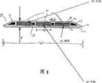
图1是在标准的电力布线中用的3-线扁平导体侧剖面图;Figure 1 is a side sectional view of a 3-wire flat conductor used in standard power wiring;
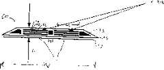
图2是在需要两个回路中用的5-线扁平导体的分解侧剖面图;Figure 2 is an exploded side sectional view of a 5-wire flat conductor used where two loops are required;
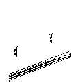
图3是在扬声器系统用的2-线扁平导体分解侧剖面图;Figure 3 is an exploded side sectional view of a 2-wire flat conductor used in a loudspeaker system;
图4是在电话中用的6-线扁平导体分解侧剖面图;Figure 4 is an exploded side sectional view of a 6-wire flat conductor used in a telephone;
图5是CATV用的2-线扁平导体分解侧剖面图;Fig. 5 is an exploded side sectional view of a 2-wire flat conductor for CATV;
图6是在低电压系统用的2-线扁平导体分解侧剖面图;Figure 6 is an exploded side sectional view of a 2-wire flat conductor used in a low voltage system;
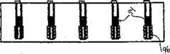
图7是通过一扁平线连接的可插的和独立的输出端的透视结构图;Fig. 7 is the perspective structural diagram of pluggable and independent output terminal connected by a flat line;
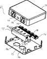
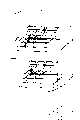
图8A是本发明输出端组件组件的分解透视图;Figure 8A is an exploded perspective view of the output end assembly of the present invention;
图8B是本发明输出端组件组件的另一个分解透视图;Figure 8B is another exploded perspective view of the output end assembly assembly of the present invention;
图8C是本发明完全构成的输出端组件的底视透视图;Figure 8C is a bottom perspective view of a fully constructed output end assembly of the present invention;
图9A是本发明扁平线到输出端框架的连接器的接口的透视图;Fig. 9 A is the perspective view of the interface of the connector of the flat wire to the output end frame of the present invention;
图9B、9C和9D分别是图9A扁平线到输出端框架的连接器的接口的顶视、侧视和底视图;9B, 9C and 9D are top view, side view and bottom view of the interface of the connector of the flat wire of FIG. 9A to the output end frame, respectively;
图9E是图9A扁平线到输出端框架连接器的底视透视图,示出长槽和电刷;Figure 9E is a bottom perspective view of the flat wire to output end frame connector of Figure 9A, showing the slot and brushes;
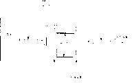
图10A是本发明扁平线到常规线的连接器的透视图;Fig. 10A is the perspective view of the connector of the present invention flat line to conventional line;
图10B、10C和10D分别是图10A扁平线到常规线的连接器的顶视、侧视和底视图;10B, 10C and 10D are top view, side view and bottom view of the connector of FIG. 10A flat line to conventional line, respectively;
图11A是本发明的三电刷凹形插头座系统的三维透视图;Figure 11A is a three-dimensional perspective view of the three-brush female socket system of the present invention;
图11B和11C分别是一侧面安装的开关的正视和侧视透视图;11B and 11C are front and side perspective views, respectively, of a side-mounted switch;
图12A是连接到天花板风扇的表面安装扁平线的透视图;Figure 12A is a perspective view of a surface mount flat wire connected to a ceiling fan;
图12B是本发明分离布线的开关实施例的透视图;Figure 12B is a perspective view of a switch embodiment of the present invention with separate wiring;
图13是扁平线/扬声器系统结构的示意图;Fig. 13 is a schematic diagram of the flat line/speaker system structure;
图14是扁平线/电话插孔系统示意图;Fig. 14 is a schematic diagram of a flat line/telephone jack system;
图15是扁平线/CATV系统的结构示意图;Fig. 15 is a structural schematic diagram of a flat line/CATV system;
图16是扁平线/嵌入照明系统结构示意图;Fig. 16 is a schematic structural diagram of a flat line/embedded lighting system;
图17是扁平线/DC电源系统结构示意图;Fig. 17 is a schematic structural diagram of a flat line/DC power supply system;
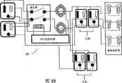
图18是不带可开关输入插头的4-输出端和3-接线端GFI检测电路示意图;Fig. 18 is a schematic diagram of a 4-output terminal and a 3-terminal GFI detection circuit without a switchable input plug;
图19是不带可开关输入插头的8-输出端GFI检测电路图示及;Fig. 19 is a schematic diagram of an 8-output GFI detection circuit without a switchable input plug;
图20是带可开关输入插头的8-输出端GFI检测电路图示;Fig. 20 is a schematic diagram of an 8-output terminal GFI detection circuit with a switchable input plug;
具体实施方式Detailed ways
一般来说,如以上所述,本发明可用于或适合用于广泛用途,包括:标准的电力布线、电话布线、扬声器布线、低压系统布线,如对讲机和安全系统、表面下照明和有线电视布线。另外本发明还包括与现有的常规圆线连接的独特的几种输出端和开关。而且,本发明也利用胶带、绝缘剥除工具和独特的连接器来实施具体方案。将对每个单独的单元进行详细讨论,并随后介绍本发明的应用。In general, as stated above, the present invention is useful or suitable for use in a wide variety of applications including: standard electrical wiring, telephone wiring, speaker wiring, low voltage system wiring such as intercom and security systems, subsurface lighting and cable television wiring . In addition, the present invention also includes several unique output terminals and switches connected with existing conventional round wires. Furthermore, the present invention also utilizes tapes, insulation stripping tools, and unique connectors to implement specific solutions. Each individual unit will be discussed in detail, followed by an introduction to the application of the invention.
每一个布线的实施例共有一基本共同的结构。但是依据具体的应用场合可对这基本共同的结构和结构单元的尺寸作出种种修改来达到所需的目的。Each wiring embodiment shares a substantially common structure. However, various modifications can be made to the basic common structure and the size of the structural units to achieve the desired purpose according to the specific application.
为了简化起见,就第一种线实施例详细地讨论该基本结构。应认为这基本结构的原理适用于所有线实施例。将对基本结构的修改作适当讨论。图中相同的标号用于表示图中相似的部件。For simplicity, the basic structure is discussed in detail with respect to the first wire embodiment. It should be considered that the principles of this basic structure apply to all wire embodiments. Modifications to the basic structure will be discussed where appropriate. The same reference numerals are used in the figures to refer to similar parts in the figures.
电线实施例Wire Example
交流电线AC wire
现参见附图,特别是图1,这里示出本发明的一标准110VAC 3-导体线实施例的分解侧剖面图。该分解剖面图仅是为说明和讨论用。在实际的3-导体实施例中,导体、绝缘和粘结剂单元之间看不到间隙(即,图1中白色区域)。这些导体、绝缘和粘结剂单元将在下面进一步说明。Referring now to the drawings, and in particular to Fig. 1, there is shown an exploded side sectional view of a standard 110VAC 3-conductor wire embodiment of the present invention. This exploded cross-sectional view is for illustration and discussion purposes only. In the actual 3-conductor embodiment, no gaps (ie, white areas in Figure 1 ) are visible between the conductor, insulation and adhesive units. These conductor, insulation and adhesive units are further described below.
一般来说,电力线10是扁平可弯曲的,它能够让使用者将电引入到室内的墙壁或天花板的任何区域。电力线10安装在墙壁或天花板的表面,从而不需要在壁和天花板内昂贵的重新布线。在该线上可以涂漆或贴纸而使其与壁面的其余部分平整贴合。Generally speaking, the
电力线10包括多个长的平行间隔开的多层导体11.如图1所示,一典型的110 VAC3-线实施例包括:一根AC接地导体、一根AC中线导体和一根火线导体。The
如图1所示,内粘结材料13分开扁平导体11,并构成外扁平导体的密封边。粘结材料13和导体11由绝缘材料薄层15包围。另外,外粘结层17贴在扁平线背后以便将该电力线贴附到需要表面上。As shown in FIG. 1, the inner
每个导体11包括一个或多个厚度为0.0004-0.020英寸的铜材料层,最好层的厚度为0.002英寸。三个铜层11a、11b和11c如图1所例示。导体层的厚度应是跨其长度和宽度均匀一致的,从而消除任何电阻热点。Each conductor 11 comprises one or more layers of copper material having a thickness of 0.0004-0.020 inches, preferably a layer having a thickness of 0.002 inches. Three copper layers 11a, 11b and 11c are illustrated in FIG. 1 . The thickness of the conductor layer should be uniform across its length and width, thereby eliminating any resistive hot spots.
具体应用场合的载流或信号的额度可以通过三种方式中任何一个单独地或组合地达到。第一,导体的宽度“w”可变化。第二,对每个导体11可重叠附加薄铜层。第三,导体11的厚度“t”可增加。The current-carrying or signal rating for a specific application can be achieved in any one of three ways, either alone or in combination. First, the width "w" of the conductor can vary. Second, an additional thin copper layer can be superimposed for each conductor 11 . Third, the thickness "t" of the conductor 11 may be increased.
对于多数的负载和电流的应用情况,每个导体一般由大约2-5个铜层组成。但应认识到,对于下面公开的实施例来说,用或多或少的层均在本发明的范围内。For most load and current applications, each conductor typically consists of about 2-5 copper layers. It should be recognized, however, that for the embodiments disclosed below, the use of more or fewer layers is within the scope of the invention.
例如,在每层约0.002英寸厚的情况下,五层铜层的导体包括绝缘约厚0.012英寸。即使这样的厚度,扁平线仍具有一极薄截面,一旦在上面涂漆或贴纸,在一个表面上几乎不可察觉出它的存在。For example, a conductor including insulation of five layers of copper is about 0.012 inches thick with each layer being about 0.002 inches thick. Even at this thickness, flat wire has an extremely thin cross-section, and once painted or pasted on it, its presence is barely perceptible on a surface.
现详细说明绝缘层15。仅用最小的厚度达到绝缘,仅在理想条件下防止导电。该绝缘层15的主要用途是线贴到表面上时有助于使线看起不凸显,以使得在安装时取得令人满意的外表。The insulating
绝缘层15也使铜导体层定向。另外绝缘材料可单独或与内部粘结剂结合使用将导电层组分开,并在不同用途的导体之间保持一安全的介电距离(如AC地线相对于中线和火线)。The insulating
如图所示,在多层扁平线10的边上,绝缘层可以但不是必须形成斜度以使其不凸显。绝缘材料可选自聚酯膜(如Dupont Mylar)、尿烷膜或聚四氟乙烯膜之类的材料。As shown, on the sides of the multilayer
应认识到其它的绝缘材料也是在本发明的范围,只要绝缘是柔软的可涂漆的及能贴在表面上的就可以用。绝缘也应是与粘结剂相容的、耐紫外线的、并具有与导体和该绝缘所粘结的表面具有相近的热膨胀和收缩特征。It should be recognized that other insulating materials are within the scope of the invention as long as the insulation is flexible, paintable and adhereable to the surface. The insulation should also be compatible with the adhesive, UV resistant, and have thermal expansion and contraction characteristics similar to those of the conductor and the surface to which the insulation is bonded.
其它希望的性质是,绝缘应经得起在安装过程中的拉力,在储存条件下不收缩或不松驰,并当用完时可拆下来。Other desirable properties are that the insulation should withstand tension during installation, not shrink or relax under storage conditions, and be removable when exhausted.
使用故障测定的电子装置预防任何绝缘的磨损、开裂、割裂、穿孔或任何其它的损伤-这些会造成电伤害不安全暴露,该故障测定的电子装置在能防止持久损害的时间范围内及时将使用者与有害电流切断。本说明书稍后讨论该电子故障测定装置,即接地故障断路器(GroundFault Interrupter)(GFI)电路。The use of fault-testing electronic devices to prevent any abrasion, cracking, splitting, perforation or any other damage to the insulation - which can cause electrical injury unsafe exposure, the fault-finding electronic device will be used in a timely manner within the time frame to prevent lasting damage cut off from harmful currents. This electronic fault detection device, the Ground Fault Interrupter (GFI) circuit, is discussed later in this specification.
现返回到图1,内粘结剂材料13应能够粘结绝缘层15。例如,胶带(如3M 9500PC)、液体结剂或这两者的结合可用作为内粘结剂。内粘结剂也有分开导电层组和在不同作用导体间保持安全介电距离的功能。另外,粘结剂13能够将在线内各组件中的间隙填平,使在表面上看不到。Returning now to FIG. 1 , the inner
内粘结剂材料13厚度约为导体11的截面高度‘t’,具体上是指内粘结剂分开导体11的位置。如图1所示,内粘结剂13可在扁平线的边上形成斜度而使其不凸显。The thickness of the inner
形成一个外粘结剂层17是为将线贴到希望贴的表面上。例如,外粘结层可以是两面胶带,一面固定到扁平线的背后,而另一面固定到墙壁或表面。另外,可以分别使用化学粘结剂,它可由任何既对绝缘层15又对扁平线10要贴的表面有良好粘结性能的粘结剂组成。An outer
例如具有0.002英寸的三层铜层制成的3-导体的扁平线10,截面高度‘t’将约为0.007-0.010英寸厚,对于额定电流15安培的线,3-导体的扁平线10的整个宽度‘w’约为2.0-2.5英寸,每个导体的宽度‘Wc’大约是0.4-0.6英寸,导体之间间隔‘Ws’大约是0.2-0.3英寸。For example, with a 3-conductor
为保证易于识别和正确安全的连接,AC接地导体的宽度‘Wc’与AC的中线和火线相比可稍增加。AC接地导体的宽度因此可较接近0.6英寸,而其它两个导体宽度可较接近0.4英寸,作为另一方案,AC接地导体的宽度也可比其它导体小。To ensure easy identification and a correct and safe connection, the width 'Wc ' of the AC ground conductor may be slightly increased compared to the AC neutral and live conductors. The width of the AC ground conductor can thus be closer to 0.6 inches, while the width of the other two conductors can be closer to 0.4 inches. Alternatively, the width of the AC ground conductor can also be smaller than the other conductors.
相近的尺寸可用于其它用途的线,但应理解在本发明的实施中,各尺寸能够有相当大的变化。Similar dimensions may be used for wires for other purposes, but it is understood that the dimensions can vary considerably in the practice of the present invention.
扁平线10为风扇、天花板照明或墙壁或艺术照明、向墙壁和天花板的具体位置供电的昂贵重布线工作,提供了一种简单而廉价的替换方案。The
在图2中示出本发明110VAC5-导体线20的分解侧视剖面图,它具有五个平行间隔开的多层铜导体。这5-导体线实施例包括上述3-导体线实施例的所有特征,附加的两个导体11提供一个第二电路。相同的或相似的部件以相同标号标示。In FIG. 2 is shown an exploded side cross-sectional view of a 110VAC 5-
该110VAC5-导体线用于一条线上希望有两个电路的场合。如一个线引向一个灯和一个风扇,或用一个带开关插头的地方。在这个实施例中,五个导体包括两个AC中线导体、两个火线导体和一个接地线导体。This 110VAC 5-conductor line is used where two circuits are desired on one line. Such as a line leading to a light and a fan, or a place with a switch plug. In this embodiment, the five conductors include two AC neutral conductors, two live conductors, and one ground conductor.
铜层的数目和厚度、导体11的宽度‘Wc’和厚度‘t’及导体之间的间隔‘Ws’基本与110VAC3-导体线是相同的。制成的扁平线20的整个宽度‘w’大约为3.5-4.25英寸。The number and thickness of copper layers, width 'Wc ' and thickness 't' of conductors 11 and spacing 'Ws ' between conductors are substantially the same as for 110VAC 3-conductor lines. The resulting
本发明的扁平线导体也可以用于构成220VAC线的实施例,如图1所示,制成的3导体的扁平线,例如具有约0.002英寸厚的四个铜层,其截面高度‘t’约0.012英寸。整个宽度‘w’约为3.0-3.5英寸,中线和火线导体宽度‘Wc’约0.4-0.6英寸,而接地导体的宽度‘w’约0.2-0.4英寸,导体之间的间隔‘Ws’约0.4-0.6英寸。The flat wire conductor of the present invention can also be used to construct the embodiment of 220VAC line, as shown in Figure 1, the flat wire of 3 conductors of making, for example has four copper layers about 0.002 inches thick, and its section height 't' About 0.012 inches. The overall width 'w' is about 3.0-3.5 inches, the neutral and live conductor width 'Wc ' is about 0.4-0.6 inches, and the ground conductor width 'w' is about 0.2-0.4 inches, the spacing between conductors is 'Ws ' About 0.4-0.6 inches.
与在3-导体110VAC电力线中一样,在3-导体220VAC电力线中接地导体宽度的不同是为便于该线与连接器的正确连接。As in the 3-conductor 110VAC power cord, the difference in ground conductor width in the 3-conductor 220VAC power cord is to facilitate proper connection of the cord to the connector.
扬声器线speaker wire
如图3所示,与上述实施例相同,本发明的扬声器线30是薄扁平的可弯曲的线,它使得使用者可将扬声器设置在室内墙壁或天花板的任何区域。扬声器线30例如可与立体声或单声组件一起用,或用于连接如‘环绕声的’强化电视或音响系统的外部扬声器。As shown in FIG. 3, same as the above-mentioned embodiment, the speaker wire 30 of the present invention is a thin, flat, bendable wire, which allows the user to place the speaker on any area of the indoor wall or ceiling. Speaker wires 30 may be used, for example, with stereo or mono components, or for connecting external speakers such as a 'surround sound' enhanced television or sound system.
扬声器30可安装到墙壁或天花板的表面,从而不要昂贵的墙内或天花板内的重新布线。该线上也可涂漆或贴纸以便与表面的其余部分平整贴合。The loudspeaker 30 can be mounted to a wall or ceiling surface, eliminating the need for costly in-wall or in-ceiling rewiring. The line can also be painted or stickered to fit evenly with the rest of the surface.
现参见图3,扬声器线30包括一对多层铜导体11,扬声器线30的导电容量最好等于10号绞合线,每个导休11一般具有两到三个铜层,在图3中前者具有的铜层11a和11b,铜层厚度约0.0004-0.020英寸,最好约为0.002英寸,应理解,铜层厚度可更小或更大,这取决于具体用途。Referring now to Fig. 3, the speaker wire 30 includes a pair of multilayer copper conductors 11, the conductive capacity of the speaker wire 30 is preferably equal to No. 10 twisted wire, and each conductor 11 generally has two to three copper layers, as shown in Fig. 3 The former has copper layers 11a and 11b with a thickness of about 0.0004-0.020 inches, preferably about 0.002 inches, it being understood that the thickness of the copper layers may be less or greater, depending on the application.
这对导体11由适当的粘结剂材料13分开,并且如前所述设两层由绝缘层15包围,可用与前述相似的绝缘材料和粘结剂。The pair of conductors 11 are separated by a suitable
根据它的用途,扬声器线30也可包括一包围着导体1的屏蔽材料18,用于减少外部信号和串扰,屏蔽材料18可以是一层或多层任何适当的金属或半金属屏蔽材料,例如,铝或喷镀金属的聚酯膜。Depending on its use, the speaker wire 30 may also include a shielding material 18 surrounding the conductor 1 for reducing external signals and crosstalk. The shielding material 18 may be one or more layers of any suitable metallic or semi-metallic shielding material, such as , aluminum or metallized polyester film.
制成的扬声器线30带三层铜层,截面高度‘t’约0.008英寸,整个宽度‘w’约2.5-3.0英寸,每个导体的宽度‘Wc’约0.6-0.8英寸,导体之间的间隔‘Ws’约0.2-0.3英寸。Loudspeaker wire 30 was fabricated with three layers of copper having a section height 't' of approximately 0.008 inches, an overall width 'w' of approximately 2.5-3.0 inches, and a width 'Wc ' of each conductor of approximately 0.6-0.8 inches, between conductors The interval 'Ws ' is about 0.2-0.3 inches.
如图3所示,线30的边可以形成倾斜状的而使其不凸显,也可提供如前所述的相似粘结层17,而用于将扬声器线30贴到适当的表面上。As shown in Figure 3, the edges of the wire 30 may be beveled so as not to protrude, or a similar
电话线telephone line
一个本发明的电话线40的说明性实施例示于图4,在此实施例中,设有六个多层的铜导体11,它们由粘结材料13分开并由绝缘层15包裹,六个导体线便于用在个人小交换机(PBX)的转接,提供一具有公共电话线入口的个人交换机。导体11大致与标准的22号电话线相当。An illustrative embodiment of a
可用两个、四个和八个多层铜导体电话线,而且,八个导体的实例近似于四个电线对绞合线(如无屏蔽的电线对绞合线(UTP)),它适合于传送数据。Two, four, and eight multilayer copper conductor telephone wires are available, and an example of eight conductors is approximately four wire-pair twisted wires (such as unshielded wire-pair twisted wire (UTP)), which is suitable for Send data.
每个导体11一般具有两个或三个铜层,在图4中铜层11a和11b表示的是前者的情况。铜层约0.0004-0.020英寸厚,最好约0.002英寸。应理解,铜层可更厚或更薄,这取决于具体用途。Each conductor 11 typically has two or three copper layers, the former being represented in FIG. 4 by copper layers 11a and 11b. The copper layer is about 0.0004-0.020 inches thick, preferably about 0.002 inches. It should be understood that the copper layer may be thicker or thinner, depending on the particular application.
制成的带有三铜层的电话线40,截面高度大约为0.008英寸,整个的宽度‘w’约1.5-3.5英寸,这取决于所用的导体11数目;每个导体的宽度‘Wc’约0.2-0.4英寸,导体之间的间隔‘Ws’约0.125-0.25英寸。A
如图4所示,线40的边可形成倾斜状而使其不凸显,也可设置与前面所述相似的外粘结层17来将电话线40贴到适当表面。As shown in Figure 4, the edges of the
有线电视CATV线CATV line
本发明的有线电视CATV线50的实施例示于图5。在此实施例中设有一对导体11,每个导体一般可有两或三个铜层,在图5中铜层11a和11b表示的是前者的情况,铜层约0.0004-0.020英寸厚,最好约为0.002英寸,应理解,可用更厚或更薄的铜层,这取决于应用场合。An embodiment of a CATV cable 50 of the present invention is shown in FIG. 5 . A pair of conductors 11 are provided in this embodiment, and each conductor generally can have two or three copper layers, and what copper layers 11a and 11b represent in Fig. 5 is the former situation, and copper layer is about 0.0004-0.020 inch thick, most Preferably about 0.002 inches, it will be appreciated that thicker or thinner layers of copper may be used, depending on the application.
如在前面实施例中所述,导体11由粘结材料13分开并由绝缘层15包裹,如图5所示,线50的边可形成倾斜状而使其不凸显,也提供与前述相似的外粘结层17,用于将线50贴到适当的表面上。As described in the previous embodiment, the conductor 11 is separated by the
制成的带有三个铜层的天线/CATV线50,截面高度‘t’大约0.008英寸,整个宽度‘w’约1.8-2.2英寸,每个导体的宽度‘Wc’约0.4-0.6英寸,如图5所示,导体之间的间隔‘Ws’约0.4-0.6英寸,这稍比前面的实施例大,这是为了减小射频干扰和提高传输质量。CATV线额定阻抗为300欧姆。Antenna/CATV wire 50 with three layers of copper was fabricated with a cross-sectional height 't' of approximately 0.008 inches, an overall width 'w' of approximately 1.8-2.2 inches, and a width 'Wc ' of each conductor of approximately 0.4-0.6 inches, As shown in FIG. 5, the spacing 'Ws ' between the conductors is about 0.4-0.6 inches, which is slightly larger than the previous embodiment, in order to reduce radio frequency interference and improve transmission quality. CATV lines have a rated impedance of 300 ohms.
低压线low voltage line
图6示出本发明的低压线60实施例,这种低压(直流)线的用途包括对讲机、安全系统和‘智能化室内装置’。图6示出两个DC电导体11。导体11的结构基本与前述的多层导体相同。内粘结材料13、绝缘层15和外结层17与前述实施例相同。Figure 6 shows an embodiment of a
每个导体11一般有两个或三个铜层,在图6中铜层11a、11b和11c表示的是后者的情况。铜层约0.0004-0.020英寸厚,最好约0.002英寸。应理解,铜层可更厚或更薄,这取决于应用场合。Each conductor 11 typically has two or three copper layers, the latter being shown in FIG. 6 as copper layers 11a, 11b and 11c. The copper layer is about 0.0004-0.020 inches thick, preferably about 0.002 inches. It should be understood that the copper layer may be thicker or thinner, depending on the application.
制成的带三层铜层的低压线60,截面高度‘t’约0.008英寸,整个宽度‘w’约1.2-1.6英寸。每个导体的宽度‘w’约0.3-0.5英寸,每根导体的宽度‘Wc’为0.3-0.5英寸,导体之间的间隔‘Ws’约0.2-0.3英寸。The
如图6所示,线60的边可形成倾斜状而使其不凸显。也可设置与前述相似的外粘结层17来将电话线60贴到适当的表面上。As shown in FIG. 6 , the sides of the
在表面下的照明用线Lighting wires under the surface
虽然用在表面下照明的薄的可弯曲线在结构上与上述110VAC3-导体和5-导体线实施例相似,其独特之处在于表面下照明线连有嵌套式的灯169。见图16。这使得使用者能够在需要表面下照明的隔间、架子或其它位置表面之下安装照明。这个实施例将在本说明书稍后讨论常规的线与扁平线系统连接装置时予以详细介绍。While the thin flexible wire used for subsurface lighting is similar in construction to the 110VAC 3-conductor and 5-conductor wire embodiments described above, it is unique in that the subsurface lighting wire has nested lights 169 attached to it. See Figure 16. This enables the user to install lighting under the surface of a cubicle, shelf, or other location where subsurface lighting is desired. This embodiment will be described in detail later in this specification when discussing conventional wire and flat wire system connection means.
电源输出端和连接器Power output and connectors
本发明包括,在本发明扁平线和常规现有电源输出端以及常规圆线系统之间形成连接点的一组电源输出端,这些连接输出端有两个基本类型,一个是直接‘可插’入到一常规的现有的电源插座中的装置,另一个是一‘独立的’表面安装装置。The invention comprises, a set of power outlets forming connection points between the flat wires of the invention and conventional existing power outlets and conventional round wire systems, these connection outlets are of two basic types, one is directly 'pluggable' One is a device that plugs into a conventional existing electrical outlet, the other is a 'stand-alone' surface mount device.
可插的连接输出端总是在标准家用电力布线装置和本发明的各种扁平线实施例之间形成一兼容接口。因此,可插的电源输出端总是在标准的电流源上。独立的装置与可插的装置通过本发明的各种扁平线实施例连接。The pluggable connection outlets always form a compatible interface between standard household electrical wiring arrangements and the various flat cord embodiments of the present invention. Therefore, pluggable power supply outputs are always on standard current sources. Stand-alone devices and pluggable devices are connected through the various flat wire embodiments of the present invention.
图7示出在可插的和独立的装置之间的典型接口结构,假设一常规的两电源插座设置在电源输出端65后面而由常规的圆形线69从墙壁66后面供电。因此,电源输出端65是直接可插型的。而电源输出端67是一没有插头附件的固定到墙上的独立电源输出端。因此这独立的电源输出口可以设置在室内任何地点,而与现有的电源插座位置无关。FIG. 7 shows a typical interface configuration between pluggable and stand-alone devices, assuming a conventional two-power outlet located behind the
例如在电力线实施例中,由常规的线69来的电流通过本发明的可插的电源输出端65和110VAC扁平线68输送到独立的电源输出端67。For example in the powerline embodiment, current from the
图8A是可插输出端装置的分解透视图,示出该装置各种内外组件。如所示,该输出口65包括侧面安装的容纳在一个输出端盖74内的插座72和73。另外,插座72和73可象标准插座结构那样安装在正面。侧面安装插座形式的优点是输出端盖可涂漆或贴纸使它与表面平整贴合。而且,如图8B所示,在输出端盖74的另一面也可设置附加的插座72′和73′,这便有四个插座。Figure 8A is an exploded perspective view of the pluggable outlet device showing various internal and external components of the device. As shown, the
可插输出端65的输出端底部75包括开口75a和75b,它们可放在常规现有输出端插座上并用螺丝或其它相似装置固定到表面上,此时输出端盖74位于底部75上。The
可插输出端65也包括一扁平线连接器76和一个带有复位按钮78的接地故障断路器(GFI)单元77。GFI单元77(它的操作稍后将在本文中讨论)包括两组凸触头79和79′,它们穿过开口75a和75b插入到与常规布线系统配套的相应的插座中,GFI单元77的功能是在扁平线穿孔或破裂时切断通到负载的电流。图8C是装好的可插电源输出端组件65的底面透视图,示出GFI凸触头79和79′通过底部件75的开口75a和75b延伸。The
独立的电源输出端67(见图7)在下述两方面不同于可插输出端65。第一,在独立的输出端中不需要设GFI单元77及其配套复位按钮78。第二,独立的输出端的底部75不需要开口75和75′,因为独立的输出端不直接与常规布线系统连接,在其它所有方面与可插和独立电源输出端是相同的。The independent power supply output 67 (see FIG. 7) differs from the
可使单个的电源输出端底部具有冲压开口75a和75b,以使它可用于可插或独立输出端组件上。A single power outlet can be provided with punched
图8B是可插电源输出端的另一个透视图,示出两组凸触头81和83,它们分别连接着扁平线连接器76和GFI单元77,应注意,扁平线连接器76和FGI单元77不是固定到底部件75上而是选择通过凸触头81和83连接到输出端盖74上。Figure 8B is another perspective view of the output end of the pluggable power supply, showing two sets of male contacts 81 and 83, which are respectively connected to the
在图8B中还示出在盖74底面上的铜框架84。铜框架84的作用是形成与插座72、72′、73和73′以及两组凸触头81和83的导电连接,如图8A所示,凸触点83插入到GFI单元77一表面上的相应的槽82中。Also shown in FIG. 8B is a copper frame 84 on the underside of the
现在详细讨论对于可插和独立电源输出端共用的扁平线连接器76,扁平线连接器76在本发明的扁平线和铜输出端框架84之间形成连接点。Discussing now in detail the
在图9A的透视图中示出这种扁平线到输出端框架的连接器90的一个例子。为说明示出的是一个5-导体的连接器组件,但应理解,该连接器可制造成与任何数目的扁平导体相连接的结构,导体可具有任何数目的铜层。An example of such a flat wire to
沿连接器90的一个表面形成多个扁平线插座92,用于容纳各个扁平线导体11。当用3-导体电线时,假若外线插座不拥挤,3-导体和5-导体电线可用相同的5-导体连接器组件90。其它线实施例具有它们自己的接口连接器90。因为连接器能够容易地交换和通过将连接器插入到在输出端盖74上固定的凸触头81中,该连接器便容易地插入到输出端盖74中,所以需要多种连接器不构成问题。A plurality of
每个扁平线插座包括多个带缝的弹簧94,用于连接多层导体11中的相应铜层(还见图9B),相应于上述多层铜导体实施例,一般形成两个到五个带缝弹簧94。Each flat wire socket includes a plurality of slotted
如图9A和9B透视图及图9C侧视图所示,在连接器90的另一表面上包括多个长凹槽98。如图8B所示,这些长凹槽98与相应的一组凸触头81相接,凸触头81只需滑入槽98中而形成连接。As shown in the perspective views of FIGS. 9A and 9B and the side view of FIG. 9C , the other surface of the
在图9E中更为清楚地看到,每个长槽98包括一系列电刷或电刷98a-98d,它们每个彼此独立运动,与凸触头81形成更好的连接和较大的接触面。As seen more clearly in FIG. 9E, each
现就一典型的5-导体而每个导体有三个铜层的实施例介绍将扁平线连接到连接器90上的顺序。首先每个导体11与一相应的扁平线插座92对齐。然后每个导体11的每个铜层插在带缝弹簧94之间。如图9D所示,带缝弹簧94通过螺丝96稍加以偏压。通过上紧该螺丝能确保使每个铜层的顶部和底部都与带缝弹簧接触。这确保了最好的导体接触,并保证每个铜层(和因此每个导体)具有相同阻抗力。The sequence for connecting the flat wires to the
最后,凸触头81和长凹槽98对齐,形成与可插或独立的电源输出端的连接,输出端盖74在面向连接器90的扁平线插座93的边上具有一小的切口,使扁平线能穿过输出端盖74到达连接器90。Finally, the male contact 81 is aligned with the
除了扁平线到输出端框架的连接器之外,还需要一第二种连接器来在常规的圆线和上述各种扁平线实施例之间的形成接口。例如,当扁平线与一壁灯、风扇或对讲系统连接时就有这样的需要。In addition to the flat wire to output frame connectors, a second type of connector is required to interface between the conventional round wire and the various flat wire embodiments described above. This is required, for example, when the flat wire is connected to a wall light, fan or intercom system.
在图10A的透视图中示出了这种连接器100的一个例子。它示出一个5-导体扁平线与常规线的连接器。为了说明,这里示出的是5-导体的连接器,但应理解,可制成任何数目的扁平导体与任何数目的常规圆导线连接的连接器。当用3-导体电力线时,若外线插座不拥挤,3-导体和3-导电线可共用一个5-导体连接器组件100,其它线实施例有它们自己的接口连接器。An example of such a
如图10A所示,连接器100沿它的一表面有多个常规的调节螺丝,为在常规圆形线布线系统(见图10B)中的通用的标准的‘绕接’连接提供一个接口,沿另一表面设有一个或多个扁平线插座102用于容纳每个扁平线导体。每个扁平线插座102包括多个带缝弹簧104(见图10D),用于接触在每个多层导体中的每一层。如图10A和10C所示,带缝弹簧104由螺丝96稍偏压,其作用与就连接器90所述的相同。扁平线导体与扁平线插座的连接与就连接器90所述是相同的。As shown in FIG. 10A, the
图11A示出一改进的三电刷插座110,它可以安装在本发明的可插65和独立67电源输出端中。Figure 11A shows a modified three
插座110包括模制的铜引线111和112,它们接触相应的电刷组件114和116。每个电刷组件包括三个电刷(114a,114b,114c;116a,116b,116c),在各组件中的每个电刷相对于其它两个独立运动。
因此,这三个电刷的组件与铜引线111和112形成较好的连接和较大的接触面。铜引线111和112的另一端延伸到铜框架84(见图8B)。另外,因为这三个电刷独立运动,插座能够更好地适应插头的扭矩。Thus, the assembly of three brushes forms a better connection and a larger contact area with the copper leads 111 and 112 . The other ends of the copper leads 111 and 112 extend to the copper frame 84 (see FIG. 8B ). Also, because the three brushes move independently, the socket is better able to accommodate the torque of the plug.
开关switch
提供了一组独特的开关以适用于本发明的线制品。这些开关可用电线连接到现有开关、或插入到现有插座输出端上或通过射频(RF)遥控电源操作。该开关主要用于上述3-导体、5-导体线和表面下照明的实施例。A unique set of switches is provided for use with the cordwork of the present invention. These switches can be wired to existing switches, or plugged into existing outlet outlets, or operated by radio frequency (RF) remote control power. This switch is primarily used for the 3-conductor, 5-conductor wire and subsurface lighting embodiments described above.
1.手柄控制、固定安装和分散接线;1. Handle control, fixed installation and decentralized wiring;
2.电容触摸开关或薄膜开关控制、固定安装及分散接线;2. Capacitive touch switch or membrane switch control, fixed installation and decentralized wiring;
3.电容式触摸开关或薄膜开关控制、固定安装及射频信号发送器/接收器对;3. Capacitive touch switch or membrane switch control, fixed installation and RF signal transmitter/receiver pair;
4.电容式触摸开关,或薄膜开关控制,手持或墙挂,射频信号发送器/接收器;和4. Capacitive touch switch, or membrane switch control, handheld or wall hanging, RF signal transmitter/receiver; and
5.电容式触摸开关或薄膜开关控制的作遮光器带指示灯,手持或墙挂,射频信号发送器/接收器。5. Capacitive touch switch or membrane switch controlled as shader with indicator light, hand-held or wall-mounted, RF signal transmitter/receiver.
不管用的开关是那具体种类,所有开关都共有某些相同的元件。各开关124’(见图12B)不是切换该AC电路,而是经过一低压线125(12VDC)发出一个信号到相应的插头,该插头开关这个AC电路,如图12B所示。Regardless of the particular type of switch used, all switches share certain elements in common. Each switch 124' (seeing Fig. 12B) is not to switch the AC circuit, but sends a signal to the corresponding plug through a low voltage line 125 (12VDC), and the plug switches the AC circuit, as shown in Fig. 12B.
如果该开关装置是硬连线,就通过电压电路耦接。这使开关在没有一适配插头装置的情况下不能用。If the switching device is hardwired, it is coupled via a voltage circuit. This renders the switch unusable without a suitable plug device.
工具tool
本发明的独特的扁平线要求同样独特的绝缘剥除工具以便于将其与连接器和现有电源输出插座连接。上述每种线实施例均有它自己的特殊工具。The unique flat wire of the present invention requires an equally unique insulation stripping tool in order to interface it with the connector and existing power outlet receptacle. Each of the wire embodiments described above has its own special tools.
设想两种形式:一种是专业电气人员或安装人员用的,另一种是非专业人员用的。专业的剥除工具设计成与操作一个常规剥除工具相似,以一次操作从导线11上切除和剥掉绝缘层17。考虑到导体厚度小,显然剥除工具应是精制的,以便能精确的切除和剥离。该精细加工会提高这些工具的成本,使它仅对专业人员用是经济可行的。Two formats are envisaged: one for professional electricians or installers, and one for non-professionals. The professional stripping tool is designed to cut and strip the
非专业人员用的第二种切割工具将线对准这剥除器,接近并垂直于导体削刮,使得使用者能够为达到导体层剥去必须的绝缘材料。然后使绝缘脱壳,用剪刀剪除。A second cutting tool for non-professionals aligns the wire with the stripper, scraping close to and perpendicular to the conductor, enabling the user to strip the insulation necessary to reach the conductor layer. The insulation is then shelled and removed with scissors.
系统使用system use
在图12A中示出说明性的一般系统实施例,包括上述各种线、输出端开关和连接器。An illustrative general system embodiment is shown in Figure 12A, including the various wires, output switches and connectors described above.
参见图12A,这里设有常规的电源插座120和开关124。一个人士想要在所示位置为一天花板风扇126布线,通常须进行昂贵的墙壁和天花板的布线工作而使电源到达该风扇。Referring to Fig. 12A, a
通过使用本发明的扁平线、电源输出端、开关和连接器,这个任务如下所述就大为简化。首先将一个可插输出端65(图8A)插入常规的电源插座120。然后,在希望的位置把一个独立的电源输出端67固定到墙上。在可插输出端65和独立输出端67以及独立电源输出端67和风扇之间布设扁平线123(如3-导体或5-导体线)。By using the flat wires, power outlets, switches and connectors of the present invention, this task is greatly simplified as described below. A pluggable outlet 65 (FIG. 8A) is first plugged into a conventional
连接器90(图12A中未示出,是图9A所示类型)将扁平线123连接到可插和独立电源输出端65和67。另外,另一个连接器100(图10A所示型的)将风扇126的常规圆线与扁平线123连接。Connector 90 (not shown in FIG. 12A , of the type shown in FIG. 9A ) connects
如上所述,扁平线123用粘结层17、一般用双面带固定到墙壁表面,在上面涂漆或贴纸而将线遮蔽。As mentioned above, the
如所示,在天花板和墙壁的结合点127处,扁平线123沿其宽度弯曲90度,因为扁平线123是贴在不同平面上的。除为了适应不同平面拐角沿扁平线宽度上弯曲任何角度外,该可弯曲线实际上能以任何角度在它自身上弯曲回来以适应在相同平面上的角度变化。As shown, at the ceiling and
例如设想在图12A中有一个第二墙壁照明装置126’。壁灯126’通过扁平线128连接着一个标准开关124。为了美观,不是在接近常规开关处装一个第二独立开关,而是将扁平线在点129和129’处弯曲45度角。扁平线基本上是在其自身上回折而达到45的转弯。Consider, for example, a second wall lighting device 126' in Figure 12A. Wall light 126' is connected to a standard switch 124 by flat wire 128. For aesthetics, instead of having a second independent switch close to the conventional switch, the flat wire is bent at a 45 degree angle at
图13-17是更为特殊的使用上面公开的扁平线的各种系统实施例的图示。这些系统简要说明如下。13-17 are illustrations of more specific embodiments of various systems using the flat wires disclosed above. These systems are briefly described below.
图13示出扁平线/常规的扬声器线的接口。为简化和易于图示,仅示出一个带立体声130的扬声器131。应理解,任何数目的扬声器可与一发明的扁平线一起使用。Figure 13 shows the flat wire/conventional speaker wire interface. For simplicity and ease of illustration, only one speaker 131 with stereo 130 is shown. It should be understood that any number of speakers may be used with an inventive flat wire.
如图所示,立体声系统130通过扁平线133连接着扬声器131。扬声器131能够设在任何希望的位置。然后常规的扬声器线136连接着墙上一独立的插头。一个第二独立插头位于新扬声器位置附近所希望的地点。然后扁平线133在两个独立的插头之间走线。然后扁平线133的整个长度可涂漆或贴纸,从而就看不见了难看而烦人的扬声器线。As shown, a stereo system 130 is connected to speakers 131 via flat cables 133 . The speaker 131 can be placed at any desired location. Conventional speaker wire 136 is then connected to a separate wall plug. A second separate plug is located at the desired location near the new speaker location. The flat wire 133 is then routed between two separate plugs. The entire length of the flat wire 133 can then be painted or stickered so that the unsightly and annoying speaker wires are invisible.
参见图14,这里是扁平线/常规电话插孔形成一电话分机的插口图示。See Figure 14, which is an illustration of a flat line/conventional telephone jack forming an extension telephone jack.
如图所示,现有的电话插孔或电话插座141通过扁平线143连接着电话分机插孔142。如图所示,一个扁平线电话装置147连接着现有的电话插孔141。然后把分机插孔142设在希望的位置,并连接到扁平线电话装置147’上。然后扁平线143连接在扁平线电话装147和147’之间。然后扁平线143的全长可涂漆或贴纸,从而就看不见了难看而烦人的电话线。As shown, an existing telephone jack or socket 141 is connected to an extension telephone jack 142 by a flat wire 143 . A flat line telephone set 147 is connected to the existing telephone jack 141 as shown. The extension jack 142 is then located at the desired location and connected to the flat line telephone set 147'. The flat line 143 is then connected between the flat line telephones 147 and 147'. The full length of the flat wire 143 can then be painted or stickered so that the unsightly and annoying phone wire is invisible.
图15是-CATV的应用图示。电缆输入151通过75欧姆的同轴电缆158进入室内。然后电缆158与75欧姆-300欧姆的转换装置157连接,转换装置157接近室内输151而设置在墙上。第二转换装置157’设在接近希望放电视机152的位置。然后扁平线153在两个转换位置之间连接。然后如上述全部扁平线上可涂漆或贴纸,从而就看不见了难看和烦人的CATV线。Fig. 15 is an application illustration of CATV. The
图16示出包括扁平线163和嵌入灯169的表面下照明的实施例。开关或插头161连接着扁平线163。嵌入灯169例如可以是20-100瓦的双头RSC底座的120V的卤素灯。扁平线可设置在希望附加照明的任何表位置,如在小隔间或架子下。然后扁平线上可涂漆或贴纸而与其余表面平整贴合。FIG. 16 shows an embodiment of subsurface lighting comprising flat wires 163 and embedded lights 169 . A switch or plug 161 is connected to a flat wire 163 . The recessed lamp 169 may be, for example, a 120V halogen lamp with 20-100 watts and a double-ended RSC base. The flat wire can be placed in any table location where additional lighting is desired, such as in a cubicle or under a shelf. The flat wires can then be painted or stickered to fit evenly with the rest of the surface.
本发明的扁平线也可用于直流电(DC)。参见图17,一直流电源171通过扁平线173连接着一个直流输出端172。与在其它系统实施例中一样,墙上的连接器在常规DC线158和扁平线153之间形成接口。The flat wire of the present invention can also be used for direct current (DC). Referring to FIG. 17 , a DC power supply 171 is connected to a DC output terminal 172 through a flat cable 173 . As in the other system embodiments, a wall connector interfaces between the
接地故障断路器(GFI)电路Ground Fault Interrupter (GFI) Circuit
因为扁平线在涂漆或贴纸后几乎看不见,稍后可能不当心将一个钉子或图片钩穿过扁平线,或因其他原因割断该线。Because the flat wire is nearly invisible after painting or stickers, it is possible to accidentally hook a nail or picture through the flat wire later, or cut the wire for other reasons.
因此,在每个系统中,装设一接地故障断路(GFI)单元77(见图8A-8C)作为一个安全措施,防止偶然穿透极薄的绝缘会发生的伤害。该接地一词是指任何人或物形成一接地线路,而不是通常的内部接地。Therefore, in each system, a Ground Fault Interrupt (GFI) unit 77 (see Figures 8A-8C) is installed as a safety measure against injury that could occur by accidental penetration of extremely thin insulation. The term ground refers to any person or thing forming a ground circuit other than the usual internal ground.
该GFI电路监控AC电路通过火线和中线导体的电流,如果测到比10毫安大的误差,通过一个电路断路器使两导体都断开。电路断路足够快来防止任何持久的有害放电。The GFI circuit monitors the AC circuit current through the live and neutral conductors, and if an error greater than 10 mA is detected, both conductors are disconnected via a circuit breaker. The circuit breaks quickly enough to prevent any permanent harmful discharge.
这个电路形成一个故障保险,而在连接前和连接后可对任何电路进行检查和重新检查。由电路来的电力形成的连接可使电路故障使电路断路器之外无电。This circuit forms a failsafe, and any circuit can be checked and rechecked before and after connection. A connection made by power from a circuit can cause a circuit to fail without power beyond the circuit breaker.
如上所述,该电路实际上位于可插电源输出端65中(见图8A-8C),输出端65插入到常规的墙壁插座中。GFI检测电路基本上是一常闭继电器。当到地面的故障电流超过某预定值,该继电器断开,中断到负载的电流,该预定值比使供电电路的过载电流保护装置动作所要的电流小。As mentioned above, the circuitry is actually located in the pluggable power supply output 65 (see Figures 8A-8C), which plugs into a conventional wall outlet. The GFI detection circuit is basically a normally closed relay. The relay opens, interrupting the current to the load when the fault current to ground exceeds a predetermined value, which is less than the current required to operate the overcurrent protection device of the supply circuit.
图18示出一标准单电路180不可开关双插头系统,它具有与一本发明4-插头、3-接线端装置连接的GFI检测电路。Figure 18 shows a standard
图19示出一标准单电路180不可开关双插头系统,它具有与本发明插头装置(4个主插头和4个分插头)连接的GFI检测电路。Figure 19 shows a standard
图20示出一标准双电路200可开关2-插头系统,因此需要两个GFI检测电路,每个分别与本发明的一个4-插头(2个主插头和2个分插头)装置连接。Figure 20 shows a standard
虽然已就上述实施例介绍了本发明。本行业人士会了解,在后附权利要求的精神和范围内,本发明在实施中可做出修改。Although the present invention has been described with respect to the above-mentioned embodiments. Those skilled in the art will appreciate that the invention may be modified in practice within the spirit and scope of the appended claims.
Claims (8)
Applications Claiming Priority (2)
| Application Number | Priority Date | Filing Date | Title |
|---|---|---|---|
| US46546695A | 1995-06-05 | 1995-06-05 | |
| US08/465,466 | 1995-06-05 |
Related Parent Applications (1)
| Application Number | Title | Priority Date | Filing Date |
|---|---|---|---|
| CN200410001234ADivisionCN100590752C (en) | 1995-06-05 | 1996-06-03 | Socket for use in an electrical outlet assembly |
Publications (2)
| Publication Number | Publication Date |
|---|---|
| CN1790816Atrue CN1790816A (en) | 2006-06-21 |
| CN100550524C CN100550524C (en) | 2009-10-14 |
Family
ID=23847929
Family Applications (3)
| Application Number | Title | Priority Date | Filing Date |
|---|---|---|---|
| CNB2005101251506AExpired - Fee RelatedCN100550524C (en) | 1995-06-05 | 1996-06-03 | the flat wire assembly |
| CNB961944420AExpired - Fee RelatedCN1139941C (en) | 1995-06-05 | 1996-06-03 | Surface mounted multi-purpose wire |
| CN200410001234AExpired - Fee RelatedCN100590752C (en) | 1995-06-05 | 1996-06-03 | Socket for use in an electrical outlet assembly |
Family Applications After (2)
| Application Number | Title | Priority Date | Filing Date |
|---|---|---|---|
| CNB961944420AExpired - Fee RelatedCN1139941C (en) | 1995-06-05 | 1996-06-03 | Surface mounted multi-purpose wire |
| CN200410001234AExpired - Fee RelatedCN100590752C (en) | 1995-06-05 | 1996-06-03 | Socket for use in an electrical outlet assembly |
Country Status (16)
| Country | Link |
|---|---|
| US (3) | US5807141A (en) |
| EP (1) | EP0830690B1 (en) |
| JP (2) | JPH11506865A (en) |
| KR (1) | KR100397581B1 (en) |
| CN (3) | CN100550524C (en) |
| AT (1) | ATE360255T1 (en) |
| AU (1) | AU703444B2 (en) |
| BR (1) | BR9608489B1 (en) |
| CA (1) | CA2220876C (en) |
| DE (1) | DE69637029T2 (en) |
| DK (1) | DK0830690T3 (en) |
| EA (1) | EA001499B1 (en) |
| ES (1) | ES2286823T3 (en) |
| NO (2) | NO323976B1 (en) |
| PT (1) | PT830690E (en) |
| WO (1) | WO1996039704A1 (en) |
Cited By (3)
| Publication number | Priority date | Publication date | Assignee | Title |
|---|---|---|---|---|
| CN112636280A (en)* | 2020-12-23 | 2021-04-09 | 广东伊莱特电器有限公司 | Junction box and carbon fiber heater |
| CN113131291A (en)* | 2021-03-11 | 2021-07-16 | 东莞市晟合科技有限公司 | Connecting wire carrying electronic component and manufacturing method thereof |
| CN116565621A (en)* | 2023-04-12 | 2023-08-08 | 常州捷翼汽车零部件有限公司 | An overall wiring harness structure with multi-layer distribution |
Families Citing this family (50)
| Publication number | Priority date | Publication date | Assignee | Title |
|---|---|---|---|---|
| US6107577A (en)* | 1995-06-05 | 2000-08-22 | Sexton; Robert Jay | Flat surface-mounted multi-purpose wire |
| US5762525A (en)* | 1996-08-06 | 1998-06-09 | Candeloro; Salvatore | Electrical wiring system |
| GB9621353D0 (en)* | 1996-10-11 | 1996-12-04 | Tunewell Technology Ltd | Improvements in or relating to a power distribution system |
| US6492595B2 (en)* | 1997-10-01 | 2002-12-10 | Decorp Americas, Inc. | Flat surface-mounted multi-purpose wire |
| FR2774497B1 (en)* | 1998-02-05 | 2000-07-21 | Daniel Ansel | METHOD USING SIGNAL ANALYSIS FOR CONTROLLING REMOTE ELECTRICAL DEVICES AND ASSOCIATED DEVICES |
| US6546098B1 (en) | 1999-06-21 | 2003-04-08 | Conexant Systems, Inc. | System and method for distributing enhanced telephony service to customer premises equipment |
| US6443746B1 (en)* | 1999-09-08 | 2002-09-03 | Jeff Yu | Multiple receptacle having a wireless coupling feature |
| JP2002334756A (en)* | 2001-05-09 | 2002-11-22 | Nichido Kogyo Kk | Receptacle |
| US6849794B1 (en) | 2001-05-14 | 2005-02-01 | Ronnie C. Lau | Multiple channel system |
| US20020186859A1 (en)* | 2001-06-12 | 2002-12-12 | Atia Gerardo W. | Framework for home theater systems |
| EP1349180B1 (en)* | 2002-03-27 | 2004-11-17 | Nexans | Electrical flat conductor ribbon cable |
| RU2244359C2 (en)* | 2002-10-18 | 2005-01-10 | Охотников Сергей Борисович | High-conductivity flat electric cable for power supply to electrical loads and for transmission of telephone, television, computer, and radio communication signals |
| US6991495B1 (en)* | 2002-10-28 | 2006-01-31 | Tower Manufacturing Corporation | Power strip with self-contained ground fault circuit interrupter module |
| US20040171288A1 (en)* | 2003-02-28 | 2004-09-02 | Tyco Electronics Corporation | Apparatus, articles of manufacture and method for a wire dress cover assembly |
| US7145073B2 (en)* | 2003-09-05 | 2006-12-05 | Southwire Company | Electrical wire and method of fabricating the electrical wire |
| US7215519B2 (en)* | 2003-10-20 | 2007-05-08 | The Boeing Company | Ground and line fault interrupt controller/adapter |
| JP3982511B2 (en)* | 2004-03-09 | 2007-09-26 | ソニー株式会社 | Flat cable manufacturing method |
| GB2415540A (en)* | 2004-06-25 | 2005-12-28 | John Frederick Davies | Flat cable system |
| US8686738B2 (en)* | 2006-07-24 | 2014-04-01 | Newire, Inc. | Electrical safety devices and systems for use with electrical wiring, and methods for using same |
| TWI477016B (en)* | 2006-07-24 | 2015-03-11 | Newire Inc | Source device for use with electrical flat wire, electrical flat wire system, method for monitoring an electrical flat wire and active safety device for use with electical flat wire |
| DE102007017571B4 (en)* | 2007-04-12 | 2009-12-31 | Phoenix Contact Gmbh & Co. Kg | Electric transfer module |
| KR100866496B1 (en)* | 2008-06-10 | 2008-11-03 | (주)동방전자 | Manufacturing method of flexible flat cable |
| JP2010041133A (en)* | 2008-07-31 | 2010-02-18 | Panasonic Electric Works Co Ltd | Information outlet apparatus |
| US9685259B2 (en) | 2009-06-19 | 2017-06-20 | 3M Innovative Properties Company | Shielded electrical cable |
| WO2010148165A2 (en) | 2009-06-19 | 2010-12-23 | 3M Innovative Properties Company | Shielded electrical cable |
| JP2011022198A (en) | 2009-07-13 | 2011-02-03 | Molex Inc | Optical connector |
| JP5290074B2 (en) | 2009-07-13 | 2013-09-18 | モレックス インコーポレイテド | Optical connector |
| CN101841141A (en)* | 2010-03-17 | 2010-09-22 | 张茂华 | Common low-tension connection box and connecting wire thereof |
| EP3200202A1 (en) | 2010-08-31 | 2017-08-02 | 3M Innovative Properties Company | Shielded electrical cable in twinaxial configuration |
| EP2522022A1 (en) | 2010-08-31 | 2012-11-14 | 3M Innovative Properties Company | Shielded electrical ribbon cable with dielectric spacing |
| WO2012030365A1 (en) | 2010-08-31 | 2012-03-08 | 3M Innovative Properties Company | High density shielded electrical cable and other shielded cables, systems, and methods |
| US12205732B2 (en) | 2010-08-31 | 2025-01-21 | 3M Innovative Properties Company | Shielded electric cable |
| CA2809345A1 (en) | 2010-08-31 | 2012-03-08 | 3M Innovative Properties Company | Connector arrangements for shielded electrical cables |
| US10147522B2 (en) | 2010-08-31 | 2018-12-04 | 3M Innovative Properties Company | Electrical characteristics of shielded electrical cables |
| CA2809044A1 (en) | 2010-08-31 | 2012-03-08 | 3M Innovative Properties Company | Shielded electrical cable |
| US8859901B2 (en) | 2010-09-23 | 2014-10-14 | 3M Innovative Properties Company | Shielded electrical cable |
| JP2012182047A (en)* | 2011-03-02 | 2012-09-20 | Auto Network Gijutsu Kenkyusho:Kk | Bus-bar set and method for manufacturing the same |
| USD699183S1 (en)* | 2012-04-24 | 2014-02-11 | WebTuner, Corp. | Television adapter with side mounted video and audio outputs, telephone and ethernet ports, and multiple power outlets |
| USD698723S1 (en)* | 2012-04-24 | 2014-02-04 | WebTuner, Corp. | Television adapter with front mounted video and audio outputs, telephone and ethernet ports, and multiple power outlets |
| US10295080B2 (en) | 2012-12-11 | 2019-05-21 | Schneider Electric Buildings, Llc | Fast attachment open end direct mount damper and valve actuator |
| WO2015017238A1 (en) | 2013-07-30 | 2015-02-05 | Andrew Llc | Hybrid cable with flat power conductors |
| KR20160064698A (en) | 2014-11-28 | 2016-06-08 | 장상욱 | the puzzle link multi-tap |
| EP3598429A1 (en)* | 2015-11-12 | 2020-01-22 | Lg Electronics Inc. | Display device |
| US10321839B2 (en) | 2016-03-31 | 2019-06-18 | General Electric Company | Lead cable for electrocardiograph systems |
| MX387759B (en) | 2017-11-16 | 2025-03-14 | Norman R Byrne | DATA OR ELECTRICAL POWER DISTRIBUTION SYSTEM. |
| US11539177B2 (en)* | 2018-06-15 | 2022-12-27 | Siemens Mobility, Inc. | Vital relay assembly for modular solid-state current-limiting |
| US11303079B2 (en) | 2019-05-28 | 2022-04-12 | Norman R. Byrne | Modular electrical system |
| RU2726630C1 (en)* | 2020-02-19 | 2020-07-15 | Борис Александрович Федкевич | Flat wire for indoor installation |
| NL2031426B1 (en)* | 2022-03-29 | 2023-10-20 | Lucas Holding B V | Vehicle charging cable |
| FR3141290A1 (en)* | 2022-10-24 | 2024-04-26 | Magik Elek Sas | Electric cable extension system, electric cable extension kit and assembly method. |
Family Cites Families (36)
| Publication number | Priority date | Publication date | Assignee | Title |
|---|---|---|---|---|
| US1687167A (en)* | 1926-03-18 | 1928-10-09 | Randolph M Mann | Connecting plug |
| US2200776A (en)* | 1937-12-08 | 1940-05-14 | Byron Jackson Co | Flat cable construction |
| US3168617A (en)* | 1962-08-27 | 1965-02-02 | Tape Cable Electronics Inc | Electric cables and method of making the same |
| CH541216A (en)* | 1972-06-16 | 1973-08-31 | Alusuisse | Process for the production of insulated electrical conductors, in particular strip-shaped multiple conductors |
| US4001652A (en)* | 1975-10-22 | 1977-01-04 | General Electric Company | Ground fault receptacle with improved stationary contact mounting and backing |
| US4030801A (en)* | 1976-08-24 | 1977-06-21 | Amp Incorporated | Electrical connector junction for carpeted floor |
| US4289370A (en)* | 1979-05-25 | 1981-09-15 | Thomas & Betts Corporation | Flat conductor cable electrical conductor junction means |
| US4313646A (en)* | 1980-02-25 | 1982-02-02 | Amp Incorporated | Power distribution system |
| US4404425A (en)* | 1980-12-05 | 1983-09-13 | Thomas & Betts Corporation | Cable assembly for undercarpet signal transmission |
| US4387949A (en)* | 1981-03-12 | 1983-06-14 | Thomas & Betts Corporation | Transition connection apparatus having grounding feature |
| US4419538A (en)* | 1981-11-13 | 1983-12-06 | W. L. Gore & Associates, Inc. | Under-carpet coaxial cable |
| FR2540683B1 (en)* | 1983-02-04 | 1989-01-06 | Assistance Maintenance Const E | DEVICE FOR SUPPLYING AN ELECTRIC RECEIVER WITH VARIABLE POSITION ON A SURFACE |
| US4567544A (en)* | 1983-10-05 | 1986-01-28 | Pass & Seymour, Inc. | Plug-in ground fault circuit interrupter module |
| US4549241A (en)* | 1984-02-13 | 1985-10-22 | General Electric Company | Ground and test arrangement for a ground fault circuit interrupter |
| US4548448A (en)* | 1984-04-05 | 1985-10-22 | New York Telephone Company | Bridging connector assembly and method of using same |
| US4602840A (en)* | 1984-06-01 | 1986-07-29 | Harvey Hubbell Incorporated | Under-carpet connection system |
| US4680423A (en)* | 1985-03-04 | 1987-07-14 | Amp Incorporated | High performance flat cable |
| US4644099A (en)* | 1985-04-11 | 1987-02-17 | Allied Corporation | Undercarpet cable |
| US4695679A (en)* | 1985-08-19 | 1987-09-22 | Thomas & Betts Corporation | Flat multiconductor cable for undercarpet wiring system |
| US4698457A (en)* | 1985-09-25 | 1987-10-06 | Thomas & Betts Corporation | Strippable shielded electrical cable assembly |
| JPH0339892Y2 (en)* | 1986-04-07 | 1991-08-22 | ||
| US4783579A (en)* | 1986-04-29 | 1988-11-08 | Amp Incorporated | Flat multi-conductor power cable with two insulating layers |
| US4927384A (en)* | 1986-08-21 | 1990-05-22 | Amp Incorporated | Flat wire to round wire electrical interconnect |
| US4768965A (en)* | 1987-01-08 | 1988-09-06 | Chang Yen C | Electrical connector with selective receptacles |
| US4771367A (en)* | 1987-05-04 | 1988-09-13 | High Q Manufacturing Co. | Electric plug with circuit breaker |
| US5109397A (en)* | 1988-04-22 | 1992-04-28 | Analogic Corporation | X-ray tomography apparatus with lateral movement compensation |
| JPH0215582A (en)* | 1988-06-30 | 1990-01-19 | Sumitomo Wiring Syst Ltd | Electrical connecting construction of sheet-shaped cable |
| US4927373A (en)* | 1989-10-26 | 1990-05-22 | Paige Manufacturing Company, Inc. | Electrical safety receptacle assembly |
| US5147218A (en)* | 1991-04-12 | 1992-09-15 | Minnesota Mining And Manufacturing Company | Pluggable modular splicing connector and bridging adapter |
| US5211584A (en)* | 1991-11-05 | 1993-05-18 | James Lee | Plug-in electrical receptacle |
| US5203712A (en)* | 1992-01-17 | 1993-04-20 | Amp Incorporated | Circuit wiring device |
| JPH05217429A (en)* | 1992-01-31 | 1993-08-27 | Yazaki Corp | Tape electric wire and method of manufacturing the same |
| US5383799A (en)* | 1993-03-26 | 1995-01-24 | Fladung; Philip E. | Multi-purpose plug-in electrical outlet adaptor |
| US5387125A (en)* | 1993-07-29 | 1995-02-07 | The Whitaker Corporation | Connector for flexible flat cable |
| US5409397A (en)* | 1993-11-15 | 1995-04-25 | Environmental Associates, Inc. | Adapter plug |
| US5500489A (en)* | 1994-07-26 | 1996-03-19 | The Whitaker Corporation | Cable for electronic retailing applications |
- 1996
- 1996-06-03DEDE69637029Tpatent/DE69637029T2/ennot_activeExpired - Lifetime
- 1996-06-03DKDK96917121Tpatent/DK0830690T3/enactive
- 1996-06-03EPEP96917121Apatent/EP0830690B1/ennot_activeExpired - Lifetime
- 1996-06-03WOPCT/US1996/008729patent/WO1996039704A1/enactiveIP Right Grant
- 1996-06-03AUAU59795/96Apatent/AU703444B2/ennot_activeCeased
- 1996-06-03CNCNB2005101251506Apatent/CN100550524C/ennot_activeExpired - Fee Related
- 1996-06-03CACA002220876Apatent/CA2220876C/ennot_activeExpired - Fee Related
- 1996-06-03ESES96917121Tpatent/ES2286823T3/ennot_activeExpired - Lifetime
- 1996-06-03BRBRPI9608489-8Apatent/BR9608489B1/ennot_activeIP Right Cessation
- 1996-06-03ATAT96917121Tpatent/ATE360255T1/enactive
- 1996-06-03CNCNB961944420Apatent/CN1139941C/ennot_activeExpired - Fee Related
- 1996-06-03CNCN200410001234Apatent/CN100590752C/ennot_activeExpired - Fee Related
- 1996-06-03PTPT96917121Tpatent/PT830690E/enunknown
- 1996-06-03EAEA199700363Apatent/EA001499B1/ennot_activeIP Right Cessation
- 1996-06-03KRKR1019970708502Apatent/KR100397581B1/ennot_activeExpired - Fee Related
- 1996-06-03JPJP9501232Apatent/JPH11506865A/ennot_activeCeased
- 1996-12-16USUS08/764,921patent/US5807141A/ennot_activeExpired - Lifetime
- 1997
- 1997-01-03USUS08/775,941patent/US5804768A/ennot_activeExpired - Lifetime
- 1997-09-04USUS08/923,260patent/US5899774A/ennot_activeExpired - Lifetime
- 1997-12-04NONO19975629Apatent/NO323976B1/ennot_activeIP Right Cessation
- 2005
- 2005-12-14JPJP2005360912Apatent/JP2006164990A/enactivePending
- 2006
- 2006-05-18NONO20062245Apatent/NO20062245L/ennot_activeApplication Discontinuation
Cited By (4)
| Publication number | Priority date | Publication date | Assignee | Title |
|---|---|---|---|---|
| CN112636280A (en)* | 2020-12-23 | 2021-04-09 | 广东伊莱特电器有限公司 | Junction box and carbon fiber heater |
| CN113131291A (en)* | 2021-03-11 | 2021-07-16 | 东莞市晟合科技有限公司 | Connecting wire carrying electronic component and manufacturing method thereof |
| CN116565621A (en)* | 2023-04-12 | 2023-08-08 | 常州捷翼汽车零部件有限公司 | An overall wiring harness structure with multi-layer distribution |
| WO2024213036A1 (en)* | 2023-04-12 | 2024-10-17 | 常州捷翼汽车零部件有限公司 | Multi-layer distributed integral wire harness structure |
Also Published As
Similar Documents
| Publication | Publication Date | Title |
|---|---|---|
| CN1790816A (en) | Output Components and Connectors | |
| US6492595B2 (en) | Flat surface-mounted multi-purpose wire | |
| US20160126683A1 (en) | Apparatus for positioning in-wall power | |
| EP1036393B1 (en) | Flat surface-mounted multi-purpose wire | |
| CA2453128C (en) | Flat surface-mounted multi-purpose wire | |
| AU739246B2 (en) | Flat surface-mounted multi-purpose wire | |
| AU761805B2 (en) | Flat surface-mounted multi-purpose wire | |
| HK1087539B (en) | Flat wire assembly | |
| HK1067230B (en) | Female receptacle for use in electrical outlet assembly | |
| HK1029650B (en) | Flat surface-mounted multi-purpose wire | |
| JP2005339979A (en) | Socket | |
| HK1003523B (en) | Flat surface-mountable multi-purpose wire | |
| KR200411268Y1 (en) | Outlet and switch equipped with wires for indoor wiring and wires for indoor wiring. | |
| MXPA97009664A (en) | Flat wire for multiple purposes mounted on a superfi |
Legal Events
| Date | Code | Title | Description |
|---|---|---|---|
| C06 | Publication | ||
| PB01 | Publication | ||
| C10 | Entry into substantive examination | ||
| SE01 | Entry into force of request for substantive examination | ||
| ASS | Succession or assignment of patent right | Owner name:NEWIRE CO.,LTD. Free format text:FORMER OWNER: ROBERT JIEYISAI GOLD Effective date:20060908 | |
| C41 | Transfer of patent application or patent right or utility model | ||
| TA01 | Transfer of patent application right | Effective date of registration:20060908 Address after:American Tennessee Applicant after:Newire Inc. Address before:Virginia Applicant before:R. J. Sexton | |
| REG | Reference to a national code | Ref country code:HK Ref legal event code:DE Ref document number:1087539 Country of ref document:HK | |
| C14 | Grant of patent or utility model | ||
| GR01 | Patent grant | ||
| REG | Reference to a national code | Ref country code:HK Ref legal event code:GR Ref document number:1087539 Country of ref document:HK | |
| C17 | Cessation of patent right | ||
| CF01 | Termination of patent right due to non-payment of annual fee | Granted publication date:20091014 Termination date:20140603 |