CN1781710A - Coating method and device - Google Patents
Coating method and deviceDownload PDFInfo
- Publication number
- CN1781710A CN1781710ACN 200510128697CN200510128697ACN1781710ACN 1781710 ACN1781710 ACN 1781710ACN 200510128697CN200510128697CN 200510128697CN 200510128697 ACN200510128697 ACN 200510128697ACN 1781710 ACN1781710 ACN 1781710A
- Authority
- CN
- China
- Prior art keywords
- nozzle
- hole
- discharge
- liquid
- ejection
- Prior art date
- Legal status (The legal status is an assumption and is not a legal conclusion. Google has not performed a legal analysis and makes no representation as to the accuracy of the status listed.)
- Pending
Links
- 238000000576coating methodMethods0.000titleclaimsabstractdescription20
- 239000007788liquidSubstances0.000claimsabstractdescription56
- 239000000758substrateSubstances0.000claimsabstractdescription24
- 239000011248coating agentSubstances0.000claimsdescription13
- 239000007921spraySubstances0.000claimsdescription10
- 239000012530fluidSubstances0.000claimsdescription3
- 239000010408filmSubstances0.000description18
- 230000007423decreaseEffects0.000description11
- 238000009826distributionMethods0.000description6
- 238000000034methodMethods0.000description6
- 239000010409thin filmSubstances0.000description6
- 238000012545processingMethods0.000description5
- 230000001681protective effectEffects0.000description5
- 239000011521glassSubstances0.000description4
- 239000004973liquid crystal related substanceSubstances0.000description4
- 238000012423maintenanceMethods0.000description3
- 238000010438heat treatmentMethods0.000description2
- 238000003754machiningMethods0.000description2
- 238000005520cutting processMethods0.000description1
- 238000013461designMethods0.000description1
- 238000010586diagramMethods0.000description1
- 230000000694effectsEffects0.000description1
- 238000005516engineering processMethods0.000description1
- 238000002474experimental methodMethods0.000description1
- 238000004519manufacturing processMethods0.000description1
- 230000002035prolonged effectEffects0.000description1
- 238000010926purgeMethods0.000description1
- 238000011084recoveryMethods0.000description1
- 238000005507sprayingMethods0.000description1
Images


Landscapes
- Nozzles (AREA)
Abstract
Description
Translated fromChinese(1)技术领域(1) Technical field
本发明涉及一种将从相互并列的多个喷嘴喷出的液体涂敷在基板上的涂敷方法及装置。The present invention relates to a coating method and device for coating a substrate with a liquid ejected from a plurality of nozzles arranged in parallel.
(2)背景技术(2) Background technology
在液晶显示装置的制造工序中,有在玻璃基板等基板上形成电路图形的成膜工序。在该成膜工序中,将从喷墨头等相互并列的多个喷嘴中喷出的液体涂敷在基板上,并通过液体在该基板上的摊开(扩散)形成定向膜、保护膜等功能性薄膜。In the manufacturing process of a liquid crystal display device, there is a film forming process of forming a circuit pattern on a substrate such as a glass substrate. In this film forming process, the liquid ejected from a plurality of nozzles arranged in parallel with each other such as an inkjet head is applied to the substrate, and the liquid is spread (diffused) on the substrate to form an orientation film, a protective film, etc. sex film.
为了在基板上形成膜厚均匀的功能性薄膜,就必须从各喷嘴以均等的喷出量喷出液体。因此,采用逐个喷嘴地调整各喷嘴的喷出量,使各喷嘴的喷出量均等化。并且,作为调整喷嘴的喷出量的技术如下所述。In order to form a functional thin film with a uniform film thickness on the substrate, it is necessary to discharge liquid from each nozzle with an equal discharge amount. Therefore, the discharge amount of each nozzle is adjusted on a nozzle-by-nozzle basis to equalize the discharge amount of each nozzle. In addition, as a technique for adjusting the discharge amount of the nozzle, it is as follows.
一种是在给予与各喷嘴的喷出孔连通的喷出腔内的液体以喷出能量时,调整产生喷出能量的压电元件的外加电压的方法。One is a method of adjusting the voltage applied to the piezoelectric element that generates the discharge energy when the liquid in the discharge chamber communicating with the discharge hole of each nozzle is given discharge energy.
调整与各喷嘴对应的压电元件的外加电压,使各喷嘴的喷出量均等的方法中,存在以下问题。In the method of adjusting the applied voltage of the piezoelectric element corresponding to each nozzle to make the discharge amounts of each nozzle equal, there are the following problems.
(a)当将在同一喷头内的喷嘴间产生的喷出量偏差通过调整压电元件的外加电压而均等化时,必须将每一喷嘴的压电元件的外加电压的调整范围扩大。因此,采用设置可调范围大的可变电阻器,但可调范围大的可变电阻器有调整是粗调的倾向,不能进行微调,喷出量的均等化不能充分地进行。另外,采用将对应喷嘴间的喷出量偏差的电阻器和微调用可变电阻器加以组合,设置在各压电元件的供电电路中,但此时电阻器的可调范围各种各样,必须准备多种电阻器。因此,保养管理作业繁杂,致使保养管理作业所需的时间延长,其结果是具有装置的工作效率降低的不良状况。(a) When adjusting the applied voltage of the piezoelectric element to equalize the variation in discharge amount generated among nozzles in the same head, the adjustment range of the applied voltage of the piezoelectric element for each nozzle must be expanded. Therefore, a variable resistor with a large adjustable range is used, but the variable resistor with a large adjustable range tends to be coarsely adjusted, fine adjustment cannot be performed, and the equalization of the discharge amount cannot be sufficiently performed. In addition, a resistor corresponding to the variation in discharge amount between nozzles and a variable resistor for fine-tuning are combined and installed in the power supply circuit of each piezoelectric element. However, the adjustable range of the resistor varies in this case. Various resistors must be prepared. Therefore, the maintenance and management work is complicated, and the time required for the maintenance and management work is prolonged. As a result, there is a disadvantage in that the operating efficiency of the device is lowered.
(b)在同一喷头内的各喷嘴的喷出量分布(例如图7(C)的●符号所示)中的喷出量最低的喷嘴(例如图7(A)的编号3喷嘴)中,在该喷嘴对应的压电元件的外加电压已经是该元件容许的最大外加电压时,必须降低其他喷嘴(例如图7(A)的编号1、编号2、编号4、编号5的喷嘴)对应的压电元件的外加电压,使所有喷嘴的喷出量降低(例如图7(C)的×符号所示)。这就意味着会产生在涂敷装置中涂敷一定膜厚所需的处理时间变长的不良状况。(b) In the nozzle with the lowest ejection amount (for example, No. 3 nozzle in FIG. 7(A) ) in the ejection amount distribution of each nozzle in the same nozzle (for example, shown by the symbol ● in FIG. 7(C), ), When the applied voltage of the piezoelectric element corresponding to the nozzle is already the maximum applied voltage allowed by the element, the voltage corresponding to other nozzles (such as nozzles No. 1, No. 2, No. 4, and No. 5 in Fig. 7(A)) must be reduced. The voltage applied to the piezoelectric element reduces the discharge amount of all the nozzles (for example, as indicated by the X mark in FIG. 7(C) ). This means that the processing time required to coat a certain film thickness in a coating apparatus will become long, and there will arise a problem.
(3)发明内容(3) Contents of the invention
本发明所要解决的问题是使从相互并列的多个喷嘴中喷出的喷出量简单地均等化。The problem to be solved by the present invention is to easily equalize the ejection amounts ejected from a plurality of nozzles arranged in parallel.
本发明的喷墨涂敷方法,将从相互并列的多个喷嘴中喷出的液体涂敷在基板上,通过互相调整各喷嘴的喷出孔的孔径或孔长,从而使从各喷嘴喷出的所述液体的喷出量均等。In the inkjet coating method of the present invention, the liquid ejected from a plurality of nozzles arranged side by side is applied on the substrate, and the diameter or hole length of the ejection holes of each nozzle is adjusted mutually, so that the liquid ejected from each nozzle The ejection amount of the liquid is equal.
另外,本发明的喷墨涂敷装置,由相互并列的多个喷嘴构成喷头,将从各喷嘴喷出的液体涂敷在基板上,通过互相调整各喷嘴的喷出孔的孔径或孔长,从而使从各喷嘴喷出的所述液体的喷出量均等。In addition, the inkjet coating device of the present invention constitutes a shower head by a plurality of nozzles arranged side by side, and the liquid ejected from each nozzle is applied on the substrate, and by adjusting the diameter or hole length of the ejection holes of each nozzle, Thereby, the ejection amount of the liquid ejected from each nozzle is equalized.
采用本发明的话,则可简单地使相互并列的多个喷嘴的喷出量均等化。According to the present invention, it is possible to easily equalize the discharge amounts of a plurality of nozzles arranged in parallel.
(4)附图说明(4) Description of drawings
图1是表示涂敷装置的主视图。Fig. 1 is a front view showing a coating device.
图2是图1的侧视图。FIG. 2 is a side view of FIG. 1 .
图3是表示喷墨头的主视图。Fig. 3 is a front view showing an inkjet head.
图4是表示喷墨头的剖视图。Fig. 4 is a cross-sectional view showing an inkjet head.
图5是沿图4的V-V线的箭头方向俯视图。Fig. 5 is a plan view along the arrow direction of line V-V in Fig. 4 .
图6是表示相对喷嘴的喷出孔的孔长变化的喷出量的增减关系的线图。FIG. 6 is a graph showing the relationship between increase and decrease of the discharge amount with respect to the change in the hole length of the discharge hole of the nozzle.
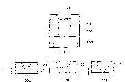
图7表示喷墨头,(A)是表示现有喷头的主视图,(B)是表示本发明喷头的主视图,(C)是表示各喷嘴的喷出量分布的线图。7 shows an inkjet head, (A) is a front view showing a conventional head, (B) is a front view showing a head of the present invention, and (C) is a line diagram showing the discharge amount distribution of each nozzle.
图8是表示调整喷嘴的喷出孔的孔长的方法的另一例子的剖视图。8 is a cross-sectional view showing another example of a method of adjusting the hole length of the discharge hole of the nozzle.
(5)具体实施方式(5) specific implementation
图1、图2所示的涂敷装置10将矩形板状的输送台13可滑动地支撑在导轨12上,该导轨12设置在水平设置的基座11的两侧。玻璃基板等的基板1保持在输送台13的上面并被输送。The
涂敷装置10在沿基座11上的基板1的输送方向的中间部立设有门形框架14,在门形框架14上横架有水平的安装构件15,在安装构件15的一侧面并列设置有多个喷墨式的喷头20。多个喷头20所形成的尺寸被设定为比基板1的宽度尺寸稍长。The
如图3~图5所示,喷头20具有从喷头主体20A的一端侧到另一端侧的单一的长槽状的主管21。与供给槽30连结的供液管31通过开关阀32与主管21的一端部相连接。在供给槽30上设置有形成配向膜、保护膜等功能性薄膜的液体用的液体补充管33、以及液体充填用加压气体管34。另外,与回收槽40连接的排液管41通过开关阀42与主管21的另一端部连接。As shown in FIGS. 3 to 5 , the
喷头20是由相互并列的多个例如编号1~编号5的5个(实际中例如为64个)喷嘴22排列为线状构成的。各喷嘴22在喷头本体20A内具有向基板1喷出液体的喷出孔22A以及与喷出孔22A连通的喷出腔22B,且将各喷出腔22B通过设在喷头本体20A上的支管22C在主管21长度方向的各位置上连接。The
喷头20通过加压气体管34中的例如N2气体将供给槽30内的液体从供液管31向主管21压送,并使其从排液管41流出,将液体充填到主管21中,然后,关闭排液管41的开关阀42,利用N2气体将供给槽30内的液体从供液管31经由主管21、支管22C向各喷嘴22的喷出腔22B压送,并使其从喷出孔22A流出,将液体充填到各喷嘴22的喷出腔22B、支管22C中。在将液体充填到喷出腔22B、支管22C中后,作为从喷出孔22A喷出液体的预备动作,停止向供给槽30内供给N2气体,同时打开未图示的放气阀,使供给槽30内的压力为大气压。此时,通过控制来自液体补充管33的液体供给量,将供给槽30内的液面高度调整为与喷头本体20A的下面高度相同或比其稍高。由此,供给槽30内的液体通过其液面和喷头本体20A下面的高度差引起的压力差而供给至供给管31,故根据因喷出而引起的喷出腔22B内的液体减少向喷出腔22B补充液体。The
喷头20将喷头本体20A的上面用挠性板23覆盖,在挠性板23的上面固定有与各喷嘴22的喷出腔22B相向的压电元件24。压电元件24与未图示的供电电路连接,被供给外加电压,使与外加电压驱动的压电元件24对应的喷嘴22的喷出腔22B产生容积变化,使充填的液体从喷出孔22A喷出,将该液体涂敷在保持在输送台13上并进行输送的基板1的上面上。涂敷在基板1上的液体通过在基板1上自然摊开(扩散)而形成定向膜、保护膜等功能性薄膜。In the
然而,涂敷装置10为在喷头20使从相互并列的多个喷嘴22中喷出的液体的喷出量均等化,而具有以下构成。However, the
(A)对于构成喷头20的喷嘴22,通过实验预先求得喷出孔22A的孔长L和喷出量K的关系。在喷出孔22A的孔径D一定而使孔长L变化时,以L/D=1时的喷出量为基准,L/D的值和喷出量K的增减值(相对基准喷出量的增减比例)的关系例如图6所示。由此可知,随着喷出孔22A的孔长L增大,喷出孔22A的流路阻力加大,而喷出量K减少。具体地说,在图6中,在喷出孔22A的孔长L为L/D=1时的孔长的1.2倍时,从该喷出孔22A喷出的喷出量比L/D=1时得到的喷出量减少10%左右。另外,在喷出孔22A的孔长L为L/D=1时的孔长的0.8倍时,从该喷出孔22A喷出的喷出量比L/D=1时得到的喷出量增加10%左右。(A) For the nozzle 22 constituting the
(B)掌握喷头20的相互并列为线状的多个喷嘴22各自的喷出量K的偏差ΔK的倾向。即,在各喷嘴22的喷出孔22A的孔长L相同的图7(A)所示的喷头中,分别对从各喷嘴22的喷出孔22A喷出的喷出量进行实际测量。并且,将喷出量最接近各喷嘴22的喷出孔22A的喷出量平均值的喷嘴22的喷出孔22A的喷出量作为基准,求得相对该喷出孔22A的喷出量的其他喷出孔22A的喷出量的偏差(增减的比例),据此得出各喷嘴22的喷出量分布。得到的喷出量分布如图7(C)的●符号所示。在图7(C)中,编号2、编号4的喷嘴22的喷出孔22A的喷出量相同,这2个喷出孔22A的喷出量最接近各喷嘴22的喷出孔22A的喷出量平均值,故选择将这2个喷出孔22A的喷出量作为基准。因此,编号2、编号4的喷嘴22的喷出孔22A的喷出量的偏差ΔK=0%。两端侧的编号1、编号5的喷嘴22的喷出孔22A的喷出量表现出比作为基准的编号2、编号4的喷嘴22的喷出孔22A的喷出量多10%(偏差ΔK=10%)的倾向。中央的编号3的喷嘴22的喷出孔22A的喷出量表现出比作为基准的编号2、编号4的喷嘴22的喷出孔22A的喷出量少10%(偏差ΔK=-10%)的倾向。(B) Grasp the tendency of the variation ΔK in the discharge amount K of each of the plurality of nozzles 22 of the
另外,各个喷嘴22的喷出孔22A的喷出量,可以通过将液体喷出在电子式重量计等的测定盘上并根据测出的重量算出,也可以从侧方向用高速摄像机对从喷出孔22A喷出的飞行中的液体进行拍摄,从其拍摄图像中求得飞行中的液体的直径,根据该直径算出喷出量。In addition, the discharge amount of the
(C)根据所述(A)、(B),通过互相调整构成喷头20的各喷嘴22的喷出孔22A的孔长L,从而实现各喷嘴22的喷出量的均等化。(C) According to the above (A) and (B), by adjusting the hole length L of the
即,在喷头20的各喷嘴22中,根据得到的所述(B)的喷出量的偏差结果,可知有在所述(A)中喷嘴22的喷出孔22A的孔长L长时喷出量减少,在孔长L短时喷出量增加的关系。因此,在排列为线状的编号1~编号5的喷嘴22中,将两端侧的编号1、编号5的喷嘴22的喷出孔22A的孔长L加长为图7(A)所示的孔长的1.2倍(调整为将图6中的喷出量K减少10%),将中央的编号3的喷嘴22的喷出孔22A的孔长L缩短为图7(A)所示的孔长的0.8倍(调整为将图6中的喷出量K增加10%)。由此,两端侧的编号1、编号5的喷嘴22的喷出量下降减少,中央的编号3的喷嘴22的喷出量上升增加,可使编号1~编号5的全部喷嘴22的喷出量大致均等化(图7(C)的○符号)。That is, in each nozzle 22 of the
例如,该调整也可通过将喷头20的喷头本体20A构成为能以图4所示的V-V线为界上下分割、更换形成有喷嘴22的下侧的喷头本体20A来进行。即,将下侧的喷头本体20A由图7(A)所示的各喷嘴22的喷出孔22A的孔长L相同的更换为图7(B)所示的喷出孔22A的孔长L根据喷嘴22的位置有所不同的。For example, this adjustment can also be performed by configuring the
在图7(A)的现有喷头20中,所有喷嘴22间的喷出量的偏差在±10%,与此相对,图7(B)的本发明的喷头20可使这些所有喷嘴22间的喷出量的偏差在±1%左右而大致均等化。该±1%左右的喷出量的偏差通过调整向各喷嘴22的压电元件24施加的电压来进行均等化。该外加电压的调整可通过可调范围比较小的可变电阻器来进行。In the existing
另外,在此,在得到各喷嘴22的喷出孔22A的喷出量分布时,选择喷出量最接近各喷出孔22A的喷出量平均值的喷出孔22A的喷出量作为基准,但也可将喷出量在各喷嘴22的喷出孔22A的喷出量中为最多的喷出孔22A的喷出量作为基准(基准喷出量),为使其他喷出孔22A的喷出量为基准喷出量而对其他喷出孔22A的孔长L进行调整。此时,因为可使各喷嘴22的喷出孔22A的喷出量比按照上述实施例调整的喷嘴22的喷出孔22A的多,故可缩短在基板上涂敷一定膜厚所需要的处理时间。In addition, here, when obtaining the discharge quantity distribution of the discharge holes 22A of each nozzle 22, the discharge quantity of the
另外,除上述情况之外,还可选择喷出量最接近各喷嘴22的喷出孔22A的喷出量中的最大值和最小值的中间值的喷出孔22A的喷出量作为基准,或者也可预先设定应从各喷嘴22的喷出孔22A喷出的喷出量并将其作为基准喷出量,或将各喷出孔22A的喷出量的平均值作为基准喷出量,或将各喷嘴22的喷出孔22A的喷出量中的最大值和最小值的中间值作为基准喷出量。In addition, in addition to the above-mentioned cases, the discharge amount of the
采用本实施例的话,可起到以下作用效果。If this embodiment is adopted, the following functions and effects can be achieved.
(a)在喷嘴22的喷出孔22A的孔长L和喷出量K之间存在预先取得的一定关系(例如图6)。因此,可事先掌握相互并列的多个喷嘴22各自的喷出量K的偏差倾向,通过改变各喷嘴22的喷出孔22A的孔长L来使该偏差大致均等化。因此,可防止处理时间增长且使涂敷精度提高。(a) There is a predetermined relationship acquired in advance between the hole length L of the
(b)因为孔长L由穿孔机的工具进深量(切削深度)决定,故使用单一的工具即可在喷嘴22的喷出孔22A上形成所有孔长L。因此,可简单地进行多个喷嘴22的喷出孔22A的加工。(b) Since the hole length L is determined by the tool depth (cutting depth) of the piercer, all the hole lengths L can be formed in the
(c)在针对同一喷头20内的各喷嘴22的喷出孔22A互相变更它们的孔长L时,利用同一工具即可应对,故不需要更换工作机床的工具。因此,可防止各喷嘴22的喷出孔22A的加工位置精度(孔间隔等)降低。由此,可尽量抑制喷出孔22A的孔间隔的不均,故可将液体以规定的间距高精度地涂敷在基板1上,例如在液晶显示装置的玻璃基板上形成定向膜、保护膜等功能性薄膜时,可使膜厚均等,提高形成在基板1上的功能性薄膜的品质。由此,可防止液晶显示装置的色彩不均匀、亮度不均匀等显示不均匀,提高显示品质。(c) When the hole lengths L of the discharge holes 22A of the nozzles 22 in the
(d)如上述(a)所述,可将在同一喷头20内的喷嘴22间产生的喷出量K的大的偏差大致均等化,故可仅将偏差的微调通过压电元件的外加电压的调整来对应。每一喷嘴22的压电元件24的外加电压的调整范围虽窄但却足够,应设置在各压电元件24的供电电路上的可变电阻器可使用可调范围小的能进行微调的电阻器,且可为单一的规格,没有必要准备多种电阻器。这样因为可使电阻器的可调范围单规格化,故可提高喷头的保养管理作业的效率,进一步使装置的运转率提高。(d) As described in (a) above, it is possible to roughly equalize the large variation in the discharge amount K generated between the nozzles 22 in the
(e)因为并不是仅通过压电元件24的外加电压的调整来进行喷嘴22的喷出量K的均等化,故不会制约压电元件24的容许最大外加电压,可通过喷出孔22A的孔长L的调整来增减喷嘴22的喷出量K。可简便提高所有喷嘴22的喷出量K,可缩短涂敷装置10涂敷一定膜厚所需的处理时间。(e) Since the discharge amount K of the nozzle 22 is not equalized only by adjusting the applied voltage of the
(f)喷墨头20可实现上述(a)~(e)。另外,作为能量发生元件除压电元件24外也可为加热板(发热电阻元件)等。(f) The
上面基于附图对本发明的实施例进行了详细说明,但本发明的具体构成不限于该实施例,在不脱离本发明主旨范围内的设计变更等也属于本发明。例如,在上述实施例中,例示了将喷嘴排列为线状的一列的情况,但并不限于此,也可配置为多列或交错状。The embodiments of the present invention have been described above in detail based on the drawings, but the specific configuration of the present invention is not limited to the embodiments, and design changes and the like within the scope not departing from the gist of the present invention also belong to the present invention. For example, in the above-mentioned embodiment, the case where the nozzles are arranged in a linear row was exemplified, but the present invention is not limited thereto, and may be arranged in a plurality of rows or in a staggered manner.
另外,对将排列为线状的多个喷嘴的喷出孔的孔长调整为从中央侧向端侧逐渐变长的例子进行了说明,但只要将喷出孔的孔长调整为使各喷嘴的喷出孔的喷出量均等即可。因此,也可通过将排列为线状的多个喷嘴分为各有规定数量喷嘴的喷嘴组、改变每一喷嘴组的喷出孔的孔长来进行调整。In addition, the example in which the length of the discharge holes of the plurality of nozzles arranged in a line is adjusted to gradually become longer from the center side to the end side has been described, but it is only necessary to adjust the hole length of the discharge holes so that each nozzle The ejection amount of the ejection holes should be equal. Therefore, adjustment can also be made by dividing the plurality of nozzles arranged in a line into nozzle groups each having a predetermined number of nozzles, and changing the hole length of the discharge hole for each nozzle group.
另外,例示了将排列为线状的喷嘴连接在单一主管上、通过该主管将从供给槽供给来的液体供给至各喷嘴的喷出腔的情况,但也可将液体从供给槽分别供给至各喷嘴的喷出腔。In addition, the case where the nozzles arranged in a line are connected to a single main pipe, and the liquid supplied from the supply tank is supplied to the discharge chamber of each nozzle through the main pipe is exemplified, but the liquid may be separately supplied from the supply tank to the discharge chamber of each nozzle. Discharge chamber of each nozzle.
另外,通过实验结果得出:在将排列为线状的喷嘴连接在单一主管上、将从该主管的一端侧供给来的液体向各喷嘴的喷出腔供给的结构的喷头中,如图7(C)的●符号所示,从各喷嘴喷出的液体的喷出量有在中央侧的喷嘴比两端侧的喷嘴少的倾向。In addition, it has been obtained through experimental results that in a nozzle head with a structure in which nozzles arranged in a line are connected to a single main pipe, and the liquid supplied from one end side of the main pipe is supplied to the discharge chamber of each nozzle, as shown in Fig. 7 As indicated by the - mark in (C), the ejection amount of the liquid ejected from each nozzle tends to be smaller in the nozzles on the center side than in the nozzles on the both end sides.
因此,在采用这种结构的喷头时,如图7(B)所示,在排列为线状的喷嘴中,也可预先将两端侧的喷嘴的喷出孔的孔长形成为比中央侧的喷嘴的喷出孔的孔长长。Therefore, when adopting the shower head of this structure, as shown in Fig. 7 (B), among the nozzles arranged in a line, it is also possible to preliminarily form the nozzles of the nozzles on the two end sides to be longer than the nozzles on the central side. The hole of the ejection hole of the nozzle is long.
此时也可使喷头的多个喷嘴各自的喷出量大致均等化。因此,例如在液晶显示装置的玻璃基板上形成定向膜、保护膜等功能性薄膜时,可提高其显示品质。Also at this time, the respective discharge amounts of the plurality of nozzles of the shower head can be substantially equalized. Therefore, for example, when a functional thin film such as an alignment film or a protective film is formed on a glass substrate of a liquid crystal display device, its display quality can be improved.
另外,以利用工具进行加工来调整喷嘴的喷出孔的孔长的情况为例进行了说明,但也可使用其他手段进行调整。In addition, the case where the hole length of the discharge hole of the nozzle is adjusted by machining with a tool has been described as an example, but other means may be used for adjustment.
例如,如图8所示,准备外形相同的圆筒形的3种孔长调节件25,该3种孔长调节件25分别具有孔长L为L1、L2、L3的喷出孔22A。另一方面,在喷头本体22A上对应孔长调节件25的形状预先形成用于嵌入孔长调节件25的凹部20B。并且,该凹部20B可选择性地嵌入3种孔长调节件25,从而调整喷出孔22A的孔长。For example, as shown in FIG. 8 , three kinds of cylindrical
另外,孔长调节件25相对凹部20B的固定采用在凹部20B的内侧面形成内螺纹部、同时在孔长调节件25的外侧面形成与所述内螺纹部对应的外螺纹部,从而拧入孔长调节件25的方式,与单纯的嵌入式相比,可确实地进行固定,同时可简单地进行拆装。In addition, the hole
另外,孔长调节件25不限定为3种,即喷出孔22A的孔长不限定为3种,也可大于等于3种。In addition, the hole
另外,各喷嘴间的喷出孔的喷出量偏差可以在容许值内,故对于喷出量相对基准喷出量在容许值内的喷出孔没有必要调整孔长。In addition, since the discharge amount variation of the discharge holes among the nozzles can be within the allowable value, it is not necessary to adjust the hole length for the discharge holes whose discharge amount is within the allowable value with respect to the reference discharge amount.
另外,以一个喷头的多个喷嘴的喷出孔的孔长调整为例进行了说明,但也可为使多个喷头的所有喷嘴的喷出孔的喷出量均等而调整各喷出孔的孔长。即,在喷头为多个时,对所有喷头的各喷嘴的喷出孔的喷出量进行实际测量,根据其平均值调整各喷嘴的喷出孔的孔长,使所有喷头的各喷嘴的喷出孔的喷出量收敛在容许的偏差范围内。In addition, the adjustment of the hole length of the discharge holes of a plurality of nozzles of a single head has been described as an example, but it is also possible to adjust the discharge amounts of the discharge holes of all the nozzles of a plurality of heads to equalize the discharge amount of each discharge hole. The hole is long. That is, when there are a plurality of shower heads, the discharge amounts of the discharge holes of each nozzle of all the shower heads are actually measured, and the length of the discharge holes of each nozzle is adjusted according to the average value, so that the spray volume of each nozzle of all the shower heads The ejection volume of the outlet hole converges within the allowable deviation range.
另外,以通过调整喷嘴的喷出孔的孔长从而使各喷嘴的液体喷出量均等为例进行了说明,但通过调整喷出孔的孔径,也可使各喷嘴的液体喷出量均等。In addition, an example of adjusting the length of the discharge hole of the nozzle to make the liquid discharge amount of each nozzle equal has been described, but the liquid discharge amount of each nozzle can also be made equal by adjusting the diameter of the discharge hole.
在此,喷出孔的液体喷出量,如果在喷出孔的孔长为一定时,有与孔径的大小成正比地增减的倾向。因此,在通过调整喷出孔的孔径从而使各喷嘴的液体喷出量均等时,可以进行调整,加大喷出量少的喷嘴的喷出孔的孔径,减小喷出量多的喷嘴的喷出孔的孔径。例如,在喷出量分布如图7(C)的●符号所示的喷嘴中,将编号1、编号5的喷嘴的喷出孔的孔径调整为比编号2、编号4的喷嘴的喷出孔的孔径小,将编号3的喷嘴的喷出孔的孔径调整为比编号2、编号4的喷嘴的喷出孔的孔径大,从而可使编号1~5的喷嘴的液体喷出量均等化。Here, the discharge amount of the liquid from the discharge hole tends to increase or decrease in proportion to the size of the hole diameter when the hole length of the discharge hole is constant. Therefore, when adjusting the aperture diameter of the ejection hole so that the liquid ejection amount of each nozzle is equal, it can be adjusted to increase the aperture diameter of the ejection hole of the nozzle with a small ejection amount and reduce the liquid ejection amount of the nozzle with a large amount of ejection. The diameter of the ejection hole. For example, in the nozzles whose discharge volume distribution is shown by the ● symbol in FIG. The hole diameter is small, and the hole diameter of the spray hole of the No. 3 nozzle is adjusted to be larger than that of the No. 2 and No. 4 nozzles, so that the liquid ejection volume of the Nos. 1 to 5 nozzles can be equalized.
另外,一个喷头的喷嘴数量以5个为例进行了说明,但也可以大于等于5个。In addition, the number of nozzles in one shower head is described as 5 as an example, but it may also be greater than or equal to 5.
Claims (6)
Applications Claiming Priority (3)
| Application Number | Priority Date | Filing Date | Title |
|---|---|---|---|
| JP2004342952 | 2004-11-26 | ||
| JP2004342952 | 2004-11-26 | ||
| JP2005324154 | 2005-11-08 |
Publications (1)
| Publication Number | Publication Date |
|---|---|
| CN1781710Atrue CN1781710A (en) | 2006-06-07 |
Family
ID=36772488
Family Applications (1)
| Application Number | Title | Priority Date | Filing Date |
|---|---|---|---|
| CN 200510128697PendingCN1781710A (en) | 2004-11-26 | 2005-11-25 | Coating method and device |
Country Status (1)
| Country | Link |
|---|---|
| CN (1) | CN1781710A (en) |
Cited By (2)
| Publication number | Priority date | Publication date | Assignee | Title |
|---|---|---|---|---|
| CN106757645A (en)* | 2017-03-06 | 2017-05-31 | 麦伟成 | A kind of new energy-conservation steel ring coating unit |
| US20220132980A1 (en)* | 2013-08-09 | 2022-05-05 | Reebok International Limited | Article of footwear with extruded components |
- 2005
- 2005-11-25CNCN 200510128697patent/CN1781710A/enactivePending
Cited By (2)
| Publication number | Priority date | Publication date | Assignee | Title |
|---|---|---|---|---|
| US20220132980A1 (en)* | 2013-08-09 | 2022-05-05 | Reebok International Limited | Article of footwear with extruded components |
| CN106757645A (en)* | 2017-03-06 | 2017-05-31 | 麦伟成 | A kind of new energy-conservation steel ring coating unit |
Similar Documents
| Publication | Publication Date | Title |
|---|---|---|
| KR100912008B1 (en) | Micro Deposition Device | |
| EP2805777B1 (en) | Coating method and device | |
| TWI453069B (en) | Method and apparatus for dispensing a viscous material on a substrate | |
| CN100445096C (en) | Industrial microdeposition system and corresponding microdeposition method | |
| US10682863B2 (en) | Liquid ejecting apparatus and control method | |
| CN106413915B (en) | Coating method | |
| TWI232977B (en) | Liquid droplet ejection apparatus, method of manufacturing electrooptic device, electrooptic device, and electronic device | |
| CN106573477B (en) | Device for printing on cylindrical object and method for printing using the device | |
| CN101164784B (en) | Head unit, droplet discharge device, and liquid discharge method | |
| TWI330595B (en) | Methods and apparatus for improved manufacturing of color filters | |
| KR20120027140A (en) | Magnetic drive for dispensing apparatus | |
| US9327312B2 (en) | Resin coating apparatus and a method for forming a resin layer using the same | |
| CN101534962A (en) | Ink ejector and ink ejection control method | |
| KR20170113191A (en) | Apparatus and Method of Forming EMI Shield Layer for Semi-conductor Package | |
| CN101314278A (en) | Arrangement method of droplet discharge head, discharge head unit, and droplet discharge device | |
| US11654681B2 (en) | Liquid ejecting head and liquid ejecting apparatus | |
| WO2018161546A1 (en) | Printing device and printing method | |
| CN101573185B (en) | Method and apparatus for filling liquid material | |
| CN1781710A (en) | Coating method and device | |
| KR20080102829A (en) | Uniform thickness thin film formation method using ink jet head | |
| CN101160181A (en) | Coating device and coating method | |
| US6527159B2 (en) | Surface mounting to an irregular surface | |
| CN103895346B (en) | A kind of ink-jet coating apparatus and spraying method | |
| KR100951995B1 (en) | Coating method and device | |
| KR20160111768A (en) | Unit for ejecting ink |
Legal Events
| Date | Code | Title | Description |
|---|---|---|---|
| C06 | Publication | ||
| PB01 | Publication | ||
| C10 | Entry into substantive examination | ||
| SE01 | Entry into force of request for substantive examination | ||
| C12 | Rejection of a patent application after its publication | ||
| RJ01 | Rejection of invention patent application after publication | Open date:20060607 |