CN1777401A - Prosthetic foot with adjustable properties and enhanced vertical load-bearing/shock-absorbing capacity - Google Patents
Prosthetic foot with adjustable properties and enhanced vertical load-bearing/shock-absorbing capacityDownload PDFInfo
- Publication number
- CN1777401A CN1777401ACNA038265281ACN03826528ACN1777401ACN 1777401 ACN1777401 ACN 1777401ACN A038265281 ACNA038265281 ACN A038265281ACN 03826528 ACN03826528 ACN 03826528ACN 1777401 ACN1777401 ACN 1777401A
- Authority
- CN
- China
- Prior art keywords
- foot
- keel
- foot keel
- prosthetic
- calf shank
- Prior art date
- Legal status (The legal status is an assumption and is not a legal conclusion. Google has not performed a legal analysis and makes no representation as to the accuracy of the status listed.)
- Granted
Links
- 210000002683footAnatomy0.000claimsabstractdescription376
- 244000309466calfSpecies0.000claimsabstractdescription120
- 210000004744fore-footAnatomy0.000claimsabstractdescription37
- 210000000544articulatio talocruralisAnatomy0.000claimsabstractdescription4
- 230000004044responseEffects0.000claimsdescription31
- 230000000694effectsEffects0.000claimsdescription21
- 230000005021gaitEffects0.000claimsdescription19
- 230000006835compressionEffects0.000claimsdescription13
- 238000007906compressionMethods0.000claimsdescription13
- 238000006243chemical reactionMethods0.000claimsdescription11
- 210000003371toeAnatomy0.000claimsdescription11
- 210000003423ankleAnatomy0.000claimsdescription8
- 238000000034methodMethods0.000claimsdescription6
- 230000035939shockEffects0.000claimsdescription5
- 210000001503jointAnatomy0.000claims1
- 230000002787reinforcementEffects0.000claims1
- 210000000452mid-footAnatomy0.000abstractdescription33
- 230000009183runningEffects0.000abstractdescription21
- 230000009191jumpingEffects0.000abstractdescription10
- 210000000548hind-footAnatomy0.000abstractdescription4
- 210000001699lower legAnatomy0.000description106
- 230000004043responsivenessEffects0.000description13
- 210000002414legAnatomy0.000description9
- 230000001965increasing effectEffects0.000description8
- 239000000463materialSubstances0.000description8
- 230000009192sprintingEffects0.000description8
- 230000005484gravityEffects0.000description7
- 239000004033plasticSubstances0.000description7
- 229920003023plasticPolymers0.000description7
- 230000001133accelerationEffects0.000description5
- 229910052782aluminiumInorganic materials0.000description5
- XAGFODPZIPBFFR-UHFFFAOYSA-NaluminiumChemical compound[Al]XAGFODPZIPBFFR-UHFFFAOYSA-N0.000description5
- 230000037396body weightEffects0.000description5
- 238000013461designMethods0.000description5
- 230000009471actionEffects0.000description4
- 230000003137locomotive effectEffects0.000description4
- 238000012986modificationMethods0.000description4
- 230000004048modificationEffects0.000description4
- 230000007423decreaseEffects0.000description3
- 239000013013elastic materialSubstances0.000description3
- 229920001971elastomerPolymers0.000description3
- 210000003141lower extremityAnatomy0.000description3
- 230000000704physical effectEffects0.000description3
- 229920001187thermosetting polymerPolymers0.000description3
- 210000002303tibiaAnatomy0.000description3
- 230000007704transitionEffects0.000description3
- 239000004593EpoxySubstances0.000description2
- RTAQQCXQSZGOHL-UHFFFAOYSA-NTitaniumChemical compound[Ti]RTAQQCXQSZGOHL-UHFFFAOYSA-N0.000description2
- 239000006096absorbing agentSubstances0.000description2
- 238000010521absorption reactionMethods0.000description2
- 230000004075alterationEffects0.000description2
- 238000002266amputationMethods0.000description2
- 210000003414extremityAnatomy0.000description2
- 239000003000extruded plasticSubstances0.000description2
- 210000002082fibulaAnatomy0.000description2
- 210000000454fifth toeAnatomy0.000description2
- 239000006260foamSubstances0.000description2
- ZMNSRFNUONFLSP-UHFFFAOYSA-NmephenoxaloneChemical compoundCOC1=CC=CC=C1OCC1OC(=O)NC1ZMNSRFNUONFLSP-UHFFFAOYSA-N0.000description2
- 229960001030mephenoxaloneDrugs0.000description2
- 230000003278mimic effectEffects0.000description2
- 230000037230mobilityEffects0.000description2
- 229920002635polyurethanePolymers0.000description2
- 239000004814polyurethaneSubstances0.000description2
- 239000010936titaniumSubstances0.000description2
- 229910052719titaniumInorganic materials0.000description2
- OKTJSMMVPCPJKN-UHFFFAOYSA-NCarbonChemical compound[C]OKTJSMMVPCPJKN-UHFFFAOYSA-N0.000description1
- 229920000049Carbon (fiber)Polymers0.000description1
- 229920000271Kevlar®Polymers0.000description1
- 229910000639Spring steelInorganic materials0.000description1
- 206010068872Toe walkingDiseases0.000description1
- 241000469816VarusSpecies0.000description1
- 230000002411adverseEffects0.000description1
- 229910045601alloyInorganic materials0.000description1
- 239000000956alloySubstances0.000description1
- 238000013459approachMethods0.000description1
- 230000000386athletic effectEffects0.000description1
- 239000004917carbon fiberSubstances0.000description1
- 230000008859changeEffects0.000description1
- 230000000295complement effectEffects0.000description1
- 230000003247decreasing effectEffects0.000description1
- 238000004146energy storageMethods0.000description1
- 230000002708enhancing effectEffects0.000description1
- 239000003822epoxy resinSubstances0.000description1
- 239000011152fibreglassSubstances0.000description1
- 239000000945fillerSubstances0.000description1
- 229910002804graphiteInorganic materials0.000description1
- 239000010439graphiteSubstances0.000description1
- 239000004761kevlarSubstances0.000description1
- 210000003127kneeAnatomy0.000description1
- 229910052751metalInorganic materials0.000description1
- 239000002184metalSubstances0.000description1
- 150000002739metalsChemical class0.000description1
- VNWKTOKETHGBQD-UHFFFAOYSA-NmethaneChemical compoundCVNWKTOKETHGBQD-UHFFFAOYSA-N0.000description1
- 238000000465mouldingMethods0.000description1
- MMMNTDFSPSQXJP-UHFFFAOYSA-Norphenadrine citrateChemical compoundOC(=O)CC(O)(C(O)=O)CC(O)=O.C=1C=CC=C(C)C=1C(OCCN(C)C)C1=CC=CC=C1MMMNTDFSPSQXJP-UHFFFAOYSA-N0.000description1
- 230000037081physical activityEffects0.000description1
- 229920000647polyepoxidePolymers0.000description1
- 229920000642polymerPolymers0.000description1
- 239000012858resilient materialSubstances0.000description1
- 230000000717retained effectEffects0.000description1
- 239000007787solidSubstances0.000description1
- 238000012546transferMethods0.000description1
Images


Classifications
- A—HUMAN NECESSITIES
- A61—MEDICAL OR VETERINARY SCIENCE; HYGIENE
- A61F—FILTERS IMPLANTABLE INTO BLOOD VESSELS; PROSTHESES; DEVICES PROVIDING PATENCY TO, OR PREVENTING COLLAPSING OF, TUBULAR STRUCTURES OF THE BODY, e.g. STENTS; ORTHOPAEDIC, NURSING OR CONTRACEPTIVE DEVICES; FOMENTATION; TREATMENT OR PROTECTION OF EYES OR EARS; BANDAGES, DRESSINGS OR ABSORBENT PADS; FIRST-AID KITS
- A61F2/00—Filters implantable into blood vessels; Prostheses, i.e. artificial substitutes or replacements for parts of the body; Appliances for connecting them with the body; Devices providing patency to, or preventing collapsing of, tubular structures of the body, e.g. stents
- A61F2/50—Prostheses not implantable in the body
- A61F2/60—Artificial legs or feet or parts thereof
- A61F2/66—Feet; Ankle joints
- A—HUMAN NECESSITIES
- A61—MEDICAL OR VETERINARY SCIENCE; HYGIENE
- A61F—FILTERS IMPLANTABLE INTO BLOOD VESSELS; PROSTHESES; DEVICES PROVIDING PATENCY TO, OR PREVENTING COLLAPSING OF, TUBULAR STRUCTURES OF THE BODY, e.g. STENTS; ORTHOPAEDIC, NURSING OR CONTRACEPTIVE DEVICES; FOMENTATION; TREATMENT OR PROTECTION OF EYES OR EARS; BANDAGES, DRESSINGS OR ABSORBENT PADS; FIRST-AID KITS
- A61F2/00—Filters implantable into blood vessels; Prostheses, i.e. artificial substitutes or replacements for parts of the body; Appliances for connecting them with the body; Devices providing patency to, or preventing collapsing of, tubular structures of the body, e.g. stents
- A61F2/50—Prostheses not implantable in the body
- A61F2/60—Artificial legs or feet or parts thereof
- A—HUMAN NECESSITIES
- A61—MEDICAL OR VETERINARY SCIENCE; HYGIENE
- A61F—FILTERS IMPLANTABLE INTO BLOOD VESSELS; PROSTHESES; DEVICES PROVIDING PATENCY TO, OR PREVENTING COLLAPSING OF, TUBULAR STRUCTURES OF THE BODY, e.g. STENTS; ORTHOPAEDIC, NURSING OR CONTRACEPTIVE DEVICES; FOMENTATION; TREATMENT OR PROTECTION OF EYES OR EARS; BANDAGES, DRESSINGS OR ABSORBENT PADS; FIRST-AID KITS
- A61F2/00—Filters implantable into blood vessels; Prostheses, i.e. artificial substitutes or replacements for parts of the body; Appliances for connecting them with the body; Devices providing patency to, or preventing collapsing of, tubular structures of the body, e.g. stents
- A61F2/50—Prostheses not implantable in the body
- A61F2/68—Operating or control means
- A61F2/74—Operating or control means fluid, i.e. hydraulic or pneumatic
- A—HUMAN NECESSITIES
- A61—MEDICAL OR VETERINARY SCIENCE; HYGIENE
- A61F—FILTERS IMPLANTABLE INTO BLOOD VESSELS; PROSTHESES; DEVICES PROVIDING PATENCY TO, OR PREVENTING COLLAPSING OF, TUBULAR STRUCTURES OF THE BODY, e.g. STENTS; ORTHOPAEDIC, NURSING OR CONTRACEPTIVE DEVICES; FOMENTATION; TREATMENT OR PROTECTION OF EYES OR EARS; BANDAGES, DRESSINGS OR ABSORBENT PADS; FIRST-AID KITS
- A61F2/00—Filters implantable into blood vessels; Prostheses, i.e. artificial substitutes or replacements for parts of the body; Appliances for connecting them with the body; Devices providing patency to, or preventing collapsing of, tubular structures of the body, e.g. stents
- A61F2/50—Prostheses not implantable in the body
- A61F2/76—Means for assembling, fitting or testing prostheses, e.g. for measuring or balancing, e.g. alignment means
- A—HUMAN NECESSITIES
- A61—MEDICAL OR VETERINARY SCIENCE; HYGIENE
- A61K—PREPARATIONS FOR MEDICAL, DENTAL OR TOILETRY PURPOSES
- A61K9/00—Medicinal preparations characterised by special physical form
- A61K9/48—Preparations in capsules, e.g. of gelatin, of chocolate
- A61K9/4816—Wall or shell material
- A—HUMAN NECESSITIES
- A61—MEDICAL OR VETERINARY SCIENCE; HYGIENE
- A61F—FILTERS IMPLANTABLE INTO BLOOD VESSELS; PROSTHESES; DEVICES PROVIDING PATENCY TO, OR PREVENTING COLLAPSING OF, TUBULAR STRUCTURES OF THE BODY, e.g. STENTS; ORTHOPAEDIC, NURSING OR CONTRACEPTIVE DEVICES; FOMENTATION; TREATMENT OR PROTECTION OF EYES OR EARS; BANDAGES, DRESSINGS OR ABSORBENT PADS; FIRST-AID KITS
- A61F2/00—Filters implantable into blood vessels; Prostheses, i.e. artificial substitutes or replacements for parts of the body; Appliances for connecting them with the body; Devices providing patency to, or preventing collapsing of, tubular structures of the body, e.g. stents
- A61F2/50—Prostheses not implantable in the body
- A61F2/60—Artificial legs or feet or parts thereof
- A61F2/66—Feet; Ankle joints
- A61F2/6607—Ankle joints
- A—HUMAN NECESSITIES
- A61—MEDICAL OR VETERINARY SCIENCE; HYGIENE
- A61F—FILTERS IMPLANTABLE INTO BLOOD VESSELS; PROSTHESES; DEVICES PROVIDING PATENCY TO, OR PREVENTING COLLAPSING OF, TUBULAR STRUCTURES OF THE BODY, e.g. STENTS; ORTHOPAEDIC, NURSING OR CONTRACEPTIVE DEVICES; FOMENTATION; TREATMENT OR PROTECTION OF EYES OR EARS; BANDAGES, DRESSINGS OR ABSORBENT PADS; FIRST-AID KITS
- A61F2/00—Filters implantable into blood vessels; Prostheses, i.e. artificial substitutes or replacements for parts of the body; Appliances for connecting them with the body; Devices providing patency to, or preventing collapsing of, tubular structures of the body, e.g. stents
- A61F2/02—Prostheses implantable into the body
- A61F2/30—Joints
- A61F2002/30001—Additional features of subject-matter classified in A61F2/28, A61F2/30 and subgroups thereof
- A61F2002/30316—The prosthesis having different structural features at different locations within the same prosthesis; Connections between prosthetic parts; Special structural features of bone or joint prostheses not otherwise provided for
- A61F2002/30329—Connections or couplings between prosthetic parts, e.g. between modular parts; Connecting elements
- A61F2002/30433—Connections or couplings between prosthetic parts, e.g. between modular parts; Connecting elements using additional screws, bolts, dowels, rivets or washers e.g. connecting screws
- A—HUMAN NECESSITIES
- A61—MEDICAL OR VETERINARY SCIENCE; HYGIENE
- A61F—FILTERS IMPLANTABLE INTO BLOOD VESSELS; PROSTHESES; DEVICES PROVIDING PATENCY TO, OR PREVENTING COLLAPSING OF, TUBULAR STRUCTURES OF THE BODY, e.g. STENTS; ORTHOPAEDIC, NURSING OR CONTRACEPTIVE DEVICES; FOMENTATION; TREATMENT OR PROTECTION OF EYES OR EARS; BANDAGES, DRESSINGS OR ABSORBENT PADS; FIRST-AID KITS
- A61F2/00—Filters implantable into blood vessels; Prostheses, i.e. artificial substitutes or replacements for parts of the body; Appliances for connecting them with the body; Devices providing patency to, or preventing collapsing of, tubular structures of the body, e.g. stents
- A61F2/02—Prostheses implantable into the body
- A61F2/30—Joints
- A61F2002/30001—Additional features of subject-matter classified in A61F2/28, A61F2/30 and subgroups thereof
- A61F2002/30316—The prosthesis having different structural features at different locations within the same prosthesis; Connections between prosthetic parts; Special structural features of bone or joint prostheses not otherwise provided for
- A61F2002/30329—Connections or couplings between prosthetic parts, e.g. between modular parts; Connecting elements
- A61F2002/30462—Connections or couplings between prosthetic parts, e.g. between modular parts; Connecting elements retained or tied with a rope, string, thread, wire or cable
- A—HUMAN NECESSITIES
- A61—MEDICAL OR VETERINARY SCIENCE; HYGIENE
- A61F—FILTERS IMPLANTABLE INTO BLOOD VESSELS; PROSTHESES; DEVICES PROVIDING PATENCY TO, OR PREVENTING COLLAPSING OF, TUBULAR STRUCTURES OF THE BODY, e.g. STENTS; ORTHOPAEDIC, NURSING OR CONTRACEPTIVE DEVICES; FOMENTATION; TREATMENT OR PROTECTION OF EYES OR EARS; BANDAGES, DRESSINGS OR ABSORBENT PADS; FIRST-AID KITS
- A61F2/00—Filters implantable into blood vessels; Prostheses, i.e. artificial substitutes or replacements for parts of the body; Appliances for connecting them with the body; Devices providing patency to, or preventing collapsing of, tubular structures of the body, e.g. stents
- A61F2/50—Prostheses not implantable in the body
- A61F2002/5001—Cosmetic coverings
- A—HUMAN NECESSITIES
- A61—MEDICAL OR VETERINARY SCIENCE; HYGIENE
- A61F—FILTERS IMPLANTABLE INTO BLOOD VESSELS; PROSTHESES; DEVICES PROVIDING PATENCY TO, OR PREVENTING COLLAPSING OF, TUBULAR STRUCTURES OF THE BODY, e.g. STENTS; ORTHOPAEDIC, NURSING OR CONTRACEPTIVE DEVICES; FOMENTATION; TREATMENT OR PROTECTION OF EYES OR EARS; BANDAGES, DRESSINGS OR ABSORBENT PADS; FIRST-AID KITS
- A61F2/00—Filters implantable into blood vessels; Prostheses, i.e. artificial substitutes or replacements for parts of the body; Appliances for connecting them with the body; Devices providing patency to, or preventing collapsing of, tubular structures of the body, e.g. stents
- A61F2/50—Prostheses not implantable in the body
- A61F2002/5003—Prostheses not implantable in the body having damping means, e.g. shock absorbers
- A61F2002/5006—Dampers, e.g. hydraulic damper
- A—HUMAN NECESSITIES
- A61—MEDICAL OR VETERINARY SCIENCE; HYGIENE
- A61F—FILTERS IMPLANTABLE INTO BLOOD VESSELS; PROSTHESES; DEVICES PROVIDING PATENCY TO, OR PREVENTING COLLAPSING OF, TUBULAR STRUCTURES OF THE BODY, e.g. STENTS; ORTHOPAEDIC, NURSING OR CONTRACEPTIVE DEVICES; FOMENTATION; TREATMENT OR PROTECTION OF EYES OR EARS; BANDAGES, DRESSINGS OR ABSORBENT PADS; FIRST-AID KITS
- A61F2/00—Filters implantable into blood vessels; Prostheses, i.e. artificial substitutes or replacements for parts of the body; Appliances for connecting them with the body; Devices providing patency to, or preventing collapsing of, tubular structures of the body, e.g. stents
- A61F2/50—Prostheses not implantable in the body
- A61F2002/5007—Prostheses not implantable in the body having elastic means different from springs, e.g. including an elastomeric insert
- A61F2002/5009—Prostheses not implantable in the body having elastic means different from springs, e.g. including an elastomeric insert having two or more elastomeric blocks
- A—HUMAN NECESSITIES
- A61—MEDICAL OR VETERINARY SCIENCE; HYGIENE
- A61F—FILTERS IMPLANTABLE INTO BLOOD VESSELS; PROSTHESES; DEVICES PROVIDING PATENCY TO, OR PREVENTING COLLAPSING OF, TUBULAR STRUCTURES OF THE BODY, e.g. STENTS; ORTHOPAEDIC, NURSING OR CONTRACEPTIVE DEVICES; FOMENTATION; TREATMENT OR PROTECTION OF EYES OR EARS; BANDAGES, DRESSINGS OR ABSORBENT PADS; FIRST-AID KITS
- A61F2/00—Filters implantable into blood vessels; Prostheses, i.e. artificial substitutes or replacements for parts of the body; Appliances for connecting them with the body; Devices providing patency to, or preventing collapsing of, tubular structures of the body, e.g. stents
- A61F2/50—Prostheses not implantable in the body
- A61F2002/5016—Prostheses not implantable in the body adjustable
- A61F2002/503—Prostheses not implantable in the body adjustable for adjusting elasticity, flexibility, spring rate or mechanical tension
- A—HUMAN NECESSITIES
- A61—MEDICAL OR VETERINARY SCIENCE; HYGIENE
- A61F—FILTERS IMPLANTABLE INTO BLOOD VESSELS; PROSTHESES; DEVICES PROVIDING PATENCY TO, OR PREVENTING COLLAPSING OF, TUBULAR STRUCTURES OF THE BODY, e.g. STENTS; ORTHOPAEDIC, NURSING OR CONTRACEPTIVE DEVICES; FOMENTATION; TREATMENT OR PROTECTION OF EYES OR EARS; BANDAGES, DRESSINGS OR ABSORBENT PADS; FIRST-AID KITS
- A61F2/00—Filters implantable into blood vessels; Prostheses, i.e. artificial substitutes or replacements for parts of the body; Appliances for connecting them with the body; Devices providing patency to, or preventing collapsing of, tubular structures of the body, e.g. stents
- A61F2/50—Prostheses not implantable in the body
- A61F2002/5016—Prostheses not implantable in the body adjustable
- A61F2002/5032—Prostheses not implantable in the body adjustable for adjusting fluid pressure
- A—HUMAN NECESSITIES
- A61—MEDICAL OR VETERINARY SCIENCE; HYGIENE
- A61F—FILTERS IMPLANTABLE INTO BLOOD VESSELS; PROSTHESES; DEVICES PROVIDING PATENCY TO, OR PREVENTING COLLAPSING OF, TUBULAR STRUCTURES OF THE BODY, e.g. STENTS; ORTHOPAEDIC, NURSING OR CONTRACEPTIVE DEVICES; FOMENTATION; TREATMENT OR PROTECTION OF EYES OR EARS; BANDAGES, DRESSINGS OR ABSORBENT PADS; FIRST-AID KITS
- A61F2/00—Filters implantable into blood vessels; Prostheses, i.e. artificial substitutes or replacements for parts of the body; Appliances for connecting them with the body; Devices providing patency to, or preventing collapsing of, tubular structures of the body, e.g. stents
- A61F2/50—Prostheses not implantable in the body
- A61F2002/5016—Prostheses not implantable in the body adjustable
- A61F2002/5033—Prostheses not implantable in the body adjustable for adjusting damping
- A—HUMAN NECESSITIES
- A61—MEDICAL OR VETERINARY SCIENCE; HYGIENE
- A61F—FILTERS IMPLANTABLE INTO BLOOD VESSELS; PROSTHESES; DEVICES PROVIDING PATENCY TO, OR PREVENTING COLLAPSING OF, TUBULAR STRUCTURES OF THE BODY, e.g. STENTS; ORTHOPAEDIC, NURSING OR CONTRACEPTIVE DEVICES; FOMENTATION; TREATMENT OR PROTECTION OF EYES OR EARS; BANDAGES, DRESSINGS OR ABSORBENT PADS; FIRST-AID KITS
- A61F2/00—Filters implantable into blood vessels; Prostheses, i.e. artificial substitutes or replacements for parts of the body; Appliances for connecting them with the body; Devices providing patency to, or preventing collapsing of, tubular structures of the body, e.g. stents
- A61F2/50—Prostheses not implantable in the body
- A61F2002/5072—Prostheses not implantable in the body having spring elements
- A61F2002/5073—Helical springs, e.g. having at least one helical spring
- A61F2002/5075—Multiple spring systems including two or more helical springs
- A—HUMAN NECESSITIES
- A61—MEDICAL OR VETERINARY SCIENCE; HYGIENE
- A61F—FILTERS IMPLANTABLE INTO BLOOD VESSELS; PROSTHESES; DEVICES PROVIDING PATENCY TO, OR PREVENTING COLLAPSING OF, TUBULAR STRUCTURES OF THE BODY, e.g. STENTS; ORTHOPAEDIC, NURSING OR CONTRACEPTIVE DEVICES; FOMENTATION; TREATMENT OR PROTECTION OF EYES OR EARS; BANDAGES, DRESSINGS OR ABSORBENT PADS; FIRST-AID KITS
- A61F2/00—Filters implantable into blood vessels; Prostheses, i.e. artificial substitutes or replacements for parts of the body; Appliances for connecting them with the body; Devices providing patency to, or preventing collapsing of, tubular structures of the body, e.g. stents
- A61F2/50—Prostheses not implantable in the body
- A61F2002/5072—Prostheses not implantable in the body having spring elements
- A61F2002/5079—Leaf springs
- A—HUMAN NECESSITIES
- A61—MEDICAL OR VETERINARY SCIENCE; HYGIENE
- A61F—FILTERS IMPLANTABLE INTO BLOOD VESSELS; PROSTHESES; DEVICES PROVIDING PATENCY TO, OR PREVENTING COLLAPSING OF, TUBULAR STRUCTURES OF THE BODY, e.g. STENTS; ORTHOPAEDIC, NURSING OR CONTRACEPTIVE DEVICES; FOMENTATION; TREATMENT OR PROTECTION OF EYES OR EARS; BANDAGES, DRESSINGS OR ABSORBENT PADS; FIRST-AID KITS
- A61F2/00—Filters implantable into blood vessels; Prostheses, i.e. artificial substitutes or replacements for parts of the body; Appliances for connecting them with the body; Devices providing patency to, or preventing collapsing of, tubular structures of the body, e.g. stents
- A61F2/50—Prostheses not implantable in the body
- A61F2002/5081—Additional features
- A61F2002/5083—Additional features modular
- A—HUMAN NECESSITIES
- A61—MEDICAL OR VETERINARY SCIENCE; HYGIENE
- A61F—FILTERS IMPLANTABLE INTO BLOOD VESSELS; PROSTHESES; DEVICES PROVIDING PATENCY TO, OR PREVENTING COLLAPSING OF, TUBULAR STRUCTURES OF THE BODY, e.g. STENTS; ORTHOPAEDIC, NURSING OR CONTRACEPTIVE DEVICES; FOMENTATION; TREATMENT OR PROTECTION OF EYES OR EARS; BANDAGES, DRESSINGS OR ABSORBENT PADS; FIRST-AID KITS
- A61F2/00—Filters implantable into blood vessels; Prostheses, i.e. artificial substitutes or replacements for parts of the body; Appliances for connecting them with the body; Devices providing patency to, or preventing collapsing of, tubular structures of the body, e.g. stents
- A61F2/50—Prostheses not implantable in the body
- A61F2/60—Artificial legs or feet or parts thereof
- A61F2002/607—Lower legs
- A—HUMAN NECESSITIES
- A61—MEDICAL OR VETERINARY SCIENCE; HYGIENE
- A61F—FILTERS IMPLANTABLE INTO BLOOD VESSELS; PROSTHESES; DEVICES PROVIDING PATENCY TO, OR PREVENTING COLLAPSING OF, TUBULAR STRUCTURES OF THE BODY, e.g. STENTS; ORTHOPAEDIC, NURSING OR CONTRACEPTIVE DEVICES; FOMENTATION; TREATMENT OR PROTECTION OF EYES OR EARS; BANDAGES, DRESSINGS OR ABSORBENT PADS; FIRST-AID KITS
- A61F2/00—Filters implantable into blood vessels; Prostheses, i.e. artificial substitutes or replacements for parts of the body; Appliances for connecting them with the body; Devices providing patency to, or preventing collapsing of, tubular structures of the body, e.g. stents
- A61F2/50—Prostheses not implantable in the body
- A61F2/60—Artificial legs or feet or parts thereof
- A61F2/66—Feet; Ankle joints
- A61F2002/6614—Feet
- A61F2002/6621—Toes
- A61F2002/6628—Big toes
- A—HUMAN NECESSITIES
- A61—MEDICAL OR VETERINARY SCIENCE; HYGIENE
- A61F—FILTERS IMPLANTABLE INTO BLOOD VESSELS; PROSTHESES; DEVICES PROVIDING PATENCY TO, OR PREVENTING COLLAPSING OF, TUBULAR STRUCTURES OF THE BODY, e.g. STENTS; ORTHOPAEDIC, NURSING OR CONTRACEPTIVE DEVICES; FOMENTATION; TREATMENT OR PROTECTION OF EYES OR EARS; BANDAGES, DRESSINGS OR ABSORBENT PADS; FIRST-AID KITS
- A61F2/00—Filters implantable into blood vessels; Prostheses, i.e. artificial substitutes or replacements for parts of the body; Appliances for connecting them with the body; Devices providing patency to, or preventing collapsing of, tubular structures of the body, e.g. stents
- A61F2/50—Prostheses not implantable in the body
- A61F2/60—Artificial legs or feet or parts thereof
- A61F2/66—Feet; Ankle joints
- A61F2002/6614—Feet
- A61F2002/6635—Metatarsals
- A—HUMAN NECESSITIES
- A61—MEDICAL OR VETERINARY SCIENCE; HYGIENE
- A61F—FILTERS IMPLANTABLE INTO BLOOD VESSELS; PROSTHESES; DEVICES PROVIDING PATENCY TO, OR PREVENTING COLLAPSING OF, TUBULAR STRUCTURES OF THE BODY, e.g. STENTS; ORTHOPAEDIC, NURSING OR CONTRACEPTIVE DEVICES; FOMENTATION; TREATMENT OR PROTECTION OF EYES OR EARS; BANDAGES, DRESSINGS OR ABSORBENT PADS; FIRST-AID KITS
- A61F2/00—Filters implantable into blood vessels; Prostheses, i.e. artificial substitutes or replacements for parts of the body; Appliances for connecting them with the body; Devices providing patency to, or preventing collapsing of, tubular structures of the body, e.g. stents
- A61F2/50—Prostheses not implantable in the body
- A61F2/60—Artificial legs or feet or parts thereof
- A61F2/66—Feet; Ankle joints
- A61F2002/6614—Feet
- A61F2002/6642—Heels
- A—HUMAN NECESSITIES
- A61—MEDICAL OR VETERINARY SCIENCE; HYGIENE
- A61F—FILTERS IMPLANTABLE INTO BLOOD VESSELS; PROSTHESES; DEVICES PROVIDING PATENCY TO, OR PREVENTING COLLAPSING OF, TUBULAR STRUCTURES OF THE BODY, e.g. STENTS; ORTHOPAEDIC, NURSING OR CONTRACEPTIVE DEVICES; FOMENTATION; TREATMENT OR PROTECTION OF EYES OR EARS; BANDAGES, DRESSINGS OR ABSORBENT PADS; FIRST-AID KITS
- A61F2/00—Filters implantable into blood vessels; Prostheses, i.e. artificial substitutes or replacements for parts of the body; Appliances for connecting them with the body; Devices providing patency to, or preventing collapsing of, tubular structures of the body, e.g. stents
- A61F2/50—Prostheses not implantable in the body
- A61F2/60—Artificial legs or feet or parts thereof
- A61F2/66—Feet; Ankle joints
- A61F2002/6614—Feet
- A61F2002/665—Soles
- A—HUMAN NECESSITIES
- A61—MEDICAL OR VETERINARY SCIENCE; HYGIENE
- A61F—FILTERS IMPLANTABLE INTO BLOOD VESSELS; PROSTHESES; DEVICES PROVIDING PATENCY TO, OR PREVENTING COLLAPSING OF, TUBULAR STRUCTURES OF THE BODY, e.g. STENTS; ORTHOPAEDIC, NURSING OR CONTRACEPTIVE DEVICES; FOMENTATION; TREATMENT OR PROTECTION OF EYES OR EARS; BANDAGES, DRESSINGS OR ABSORBENT PADS; FIRST-AID KITS
- A61F2/00—Filters implantable into blood vessels; Prostheses, i.e. artificial substitutes or replacements for parts of the body; Appliances for connecting them with the body; Devices providing patency to, or preventing collapsing of, tubular structures of the body, e.g. stents
- A61F2/50—Prostheses not implantable in the body
- A61F2/60—Artificial legs or feet or parts thereof
- A61F2/66—Feet; Ankle joints
- A61F2002/6614—Feet
- A61F2002/6657—Feet having a plate-like or strip-like spring element, e.g. an energy-storing cantilever spring keel
- A61F2002/6664—Dual structures made of two connected cantilevered leaf springs
- A—HUMAN NECESSITIES
- A61—MEDICAL OR VETERINARY SCIENCE; HYGIENE
- A61F—FILTERS IMPLANTABLE INTO BLOOD VESSELS; PROSTHESES; DEVICES PROVIDING PATENCY TO, OR PREVENTING COLLAPSING OF, TUBULAR STRUCTURES OF THE BODY, e.g. STENTS; ORTHOPAEDIC, NURSING OR CONTRACEPTIVE DEVICES; FOMENTATION; TREATMENT OR PROTECTION OF EYES OR EARS; BANDAGES, DRESSINGS OR ABSORBENT PADS; FIRST-AID KITS
- A61F2/00—Filters implantable into blood vessels; Prostheses, i.e. artificial substitutes or replacements for parts of the body; Appliances for connecting them with the body; Devices providing patency to, or preventing collapsing of, tubular structures of the body, e.g. stents
- A61F2/50—Prostheses not implantable in the body
- A61F2/60—Artificial legs or feet or parts thereof
- A61F2/66—Feet; Ankle joints
- A61F2002/6614—Feet
- A61F2002/6657—Feet having a plate-like or strip-like spring element, e.g. an energy-storing cantilever spring keel
- A61F2002/6671—C-shaped
- A—HUMAN NECESSITIES
- A61—MEDICAL OR VETERINARY SCIENCE; HYGIENE
- A61F—FILTERS IMPLANTABLE INTO BLOOD VESSELS; PROSTHESES; DEVICES PROVIDING PATENCY TO, OR PREVENTING COLLAPSING OF, TUBULAR STRUCTURES OF THE BODY, e.g. STENTS; ORTHOPAEDIC, NURSING OR CONTRACEPTIVE DEVICES; FOMENTATION; TREATMENT OR PROTECTION OF EYES OR EARS; BANDAGES, DRESSINGS OR ABSORBENT PADS; FIRST-AID KITS
- A61F2/00—Filters implantable into blood vessels; Prostheses, i.e. artificial substitutes or replacements for parts of the body; Appliances for connecting them with the body; Devices providing patency to, or preventing collapsing of, tubular structures of the body, e.g. stents
- A61F2/50—Prostheses not implantable in the body
- A61F2/60—Artificial legs or feet or parts thereof
- A61F2/66—Feet; Ankle joints
- A61F2002/6614—Feet
- A61F2002/6657—Feet having a plate-like or strip-like spring element, e.g. an energy-storing cantilever spring keel
- A61F2002/6678—L-shaped
- A—HUMAN NECESSITIES
- A61—MEDICAL OR VETERINARY SCIENCE; HYGIENE
- A61F—FILTERS IMPLANTABLE INTO BLOOD VESSELS; PROSTHESES; DEVICES PROVIDING PATENCY TO, OR PREVENTING COLLAPSING OF, TUBULAR STRUCTURES OF THE BODY, e.g. STENTS; ORTHOPAEDIC, NURSING OR CONTRACEPTIVE DEVICES; FOMENTATION; TREATMENT OR PROTECTION OF EYES OR EARS; BANDAGES, DRESSINGS OR ABSORBENT PADS; FIRST-AID KITS
- A61F2/00—Filters implantable into blood vessels; Prostheses, i.e. artificial substitutes or replacements for parts of the body; Appliances for connecting them with the body; Devices providing patency to, or preventing collapsing of, tubular structures of the body, e.g. stents
- A61F2/50—Prostheses not implantable in the body
- A61F2/60—Artificial legs or feet or parts thereof
- A61F2/66—Feet; Ankle joints
- A61F2002/6614—Feet
- A61F2002/6657—Feet having a plate-like or strip-like spring element, e.g. an energy-storing cantilever spring keel
- A61F2002/6685—S-shaped
- A—HUMAN NECESSITIES
- A61—MEDICAL OR VETERINARY SCIENCE; HYGIENE
- A61F—FILTERS IMPLANTABLE INTO BLOOD VESSELS; PROSTHESES; DEVICES PROVIDING PATENCY TO, OR PREVENTING COLLAPSING OF, TUBULAR STRUCTURES OF THE BODY, e.g. STENTS; ORTHOPAEDIC, NURSING OR CONTRACEPTIVE DEVICES; FOMENTATION; TREATMENT OR PROTECTION OF EYES OR EARS; BANDAGES, DRESSINGS OR ABSORBENT PADS; FIRST-AID KITS
- A61F2/00—Filters implantable into blood vessels; Prostheses, i.e. artificial substitutes or replacements for parts of the body; Appliances for connecting them with the body; Devices providing patency to, or preventing collapsing of, tubular structures of the body, e.g. stents
- A61F2/50—Prostheses not implantable in the body
- A61F2/68—Operating or control means
- A61F2/70—Operating or control means electrical
- A61F2002/704—Operating or control means electrical computer-controlled, e.g. robotic control
- A—HUMAN NECESSITIES
- A61—MEDICAL OR VETERINARY SCIENCE; HYGIENE
- A61F—FILTERS IMPLANTABLE INTO BLOOD VESSELS; PROSTHESES; DEVICES PROVIDING PATENCY TO, OR PREVENTING COLLAPSING OF, TUBULAR STRUCTURES OF THE BODY, e.g. STENTS; ORTHOPAEDIC, NURSING OR CONTRACEPTIVE DEVICES; FOMENTATION; TREATMENT OR PROTECTION OF EYES OR EARS; BANDAGES, DRESSINGS OR ABSORBENT PADS; FIRST-AID KITS
- A61F2/00—Filters implantable into blood vessels; Prostheses, i.e. artificial substitutes or replacements for parts of the body; Appliances for connecting them with the body; Devices providing patency to, or preventing collapsing of, tubular structures of the body, e.g. stents
- A61F2/50—Prostheses not implantable in the body
- A61F2/76—Means for assembling, fitting or testing prostheses, e.g. for measuring or balancing, e.g. alignment means
- A61F2002/7615—Measuring means
- A—HUMAN NECESSITIES
- A61—MEDICAL OR VETERINARY SCIENCE; HYGIENE
- A61F—FILTERS IMPLANTABLE INTO BLOOD VESSELS; PROSTHESES; DEVICES PROVIDING PATENCY TO, OR PREVENTING COLLAPSING OF, TUBULAR STRUCTURES OF THE BODY, e.g. STENTS; ORTHOPAEDIC, NURSING OR CONTRACEPTIVE DEVICES; FOMENTATION; TREATMENT OR PROTECTION OF EYES OR EARS; BANDAGES, DRESSINGS OR ABSORBENT PADS; FIRST-AID KITS
- A61F2220/00—Fixations or connections for prostheses classified in groups A61F2/00 - A61F2/26 or A61F2/82 or A61F9/00 or A61F11/00 or subgroups thereof
- A61F2220/0025—Connections or couplings between prosthetic parts, e.g. between modular parts; Connecting elements
- A61F2220/0041—Connections or couplings between prosthetic parts, e.g. between modular parts; Connecting elements using additional screws, bolts, dowels or rivets, e.g. connecting screws
- A—HUMAN NECESSITIES
- A61—MEDICAL OR VETERINARY SCIENCE; HYGIENE
- A61F—FILTERS IMPLANTABLE INTO BLOOD VESSELS; PROSTHESES; DEVICES PROVIDING PATENCY TO, OR PREVENTING COLLAPSING OF, TUBULAR STRUCTURES OF THE BODY, e.g. STENTS; ORTHOPAEDIC, NURSING OR CONTRACEPTIVE DEVICES; FOMENTATION; TREATMENT OR PROTECTION OF EYES OR EARS; BANDAGES, DRESSINGS OR ABSORBENT PADS; FIRST-AID KITS
- A61F2220/00—Fixations or connections for prostheses classified in groups A61F2/00 - A61F2/26 or A61F2/82 or A61F9/00 or A61F11/00 or subgroups thereof
- A61F2220/0025—Connections or couplings between prosthetic parts, e.g. between modular parts; Connecting elements
- A61F2220/0075—Connections or couplings between prosthetic parts, e.g. between modular parts; Connecting elements sutured, ligatured or stitched, retained or tied with a rope, string, thread, wire or cable
Landscapes
- Health & Medical Sciences (AREA)
- Transplantation (AREA)
- Life Sciences & Earth Sciences (AREA)
- Veterinary Medicine (AREA)
- Public Health (AREA)
- General Health & Medical Sciences (AREA)
- Animal Behavior & Ethology (AREA)
- Engineering & Computer Science (AREA)
- Vascular Medicine (AREA)
- Heart & Thoracic Surgery (AREA)
- Biomedical Technology (AREA)
- Oral & Maxillofacial Surgery (AREA)
- Cardiology (AREA)
- Orthopedic Medicine & Surgery (AREA)
- Chemical & Material Sciences (AREA)
- Medicinal Chemistry (AREA)
- Pharmacology & Pharmacy (AREA)
- Epidemiology (AREA)
- Prostheses (AREA)
- Finger-Pressure Massage (AREA)
- Orthopedics, Nursing, And Contraception (AREA)
- Thermotherapy And Cooling Therapy Devices (AREA)
Abstract
Description
Translated fromChinese技术领域technical field
本发明涉及一种可提供增强的涉及到应用力学的动态响应能力的高性能假足。The present invention relates to a high performance prosthetic foot that provides enhanced dynamic responsiveness related to applied mechanics.
背景技术Background technique
在Martin等人的美国专利No.5897594中公开了一种用于假腿的无关节式人造足。与早期的具有设置了关节以模仿踝功能的刚性结构的人造足的解决方案不同,Martin等人的无关节式人造足采用了设置于足模制物中的弹性足嵌件。该嵌件在纵向截面上为大致C形设计,具有朝向后方的开口,采用其上方C形肢状物来承接假腿的负载,并通过其下方C形肢状物来将该负载传递到与之相连的板簧上。在从下方看去时,板簧为凸起的设计,并且基本上平行于脚底区域延伸,向前超过足嵌件而进入到足尖区域中。Martin等人的发明的目的是针对减小脚跟的冲击、弹性、跟-趾行走以及横向稳定性来改善无关节式人造足,从而允许穿用者可自然地行走,其意图是允许穿用者正常行走,并且还可进行身体锻炼以及进行体育运动。然而,这种已知人造足的动态响应特性是有限的。需要提供一种具有增强的应用力学设计特征的高性能假足,该设计特征可增强截肢者的涉及到例如跑步、跳跃、短跑、起跑、制动以及急停活动的运动能力。A non-articulated artificial foot for a prosthetic leg is disclosed in US Patent No. 5,897,594 to Martin et al. Unlike earlier artificial foot solutions that had a rigid structure articulated to mimic the function of the ankle, the articulating artificial foot of Martin et al. employed an elastic foot insert set within the foot moulding. The insert has a roughly C-shaped design in longitudinal section, with an opening facing the rear, and uses its upper C-shaped limb to take the load of the prosthetic leg and transmits the load to the connected to the leaf spring. Seen from below, the leaf spring is of convex design and runs essentially parallel to the sole area, forward beyond the foot insert into the toe area. The purpose of Martin et al.'s invention is to improve the articulating artificial foot with regard to reducing heel impact, elasticity, heel-toe walking, and lateral stability, thereby allowing the wearer to walk naturally, the intention being to allow the wearer Walk normally, and can also engage in physical activity and play sports. However, the dynamic response properties of such known artificial feet are limited. There is a need to provide a high performance prosthetic foot with enhanced applied mechanical design features that enhance the amputee's locomotor capabilities involving activities such as running, jumping, sprinting, starting, braking, and emergency stops.
Van L.Philips提出了另外的假足,据称其能够给截肢者提供可从事多种活动的灵活性和机动性,这些活动在过去因现有技术假体的结构限制和相应性能而无法进行。这些已知的假足可支持跑步、跳跃和其它活动,据报道,它可以与穿用者的正常足相同的方式来使用。例如可参见美国专利No.6071313;No.5993488;No.5899944;No.5800569;No.5800568;No.5728177;No.5728176;No.5824112;No.5593457;No.5514185;No.5181932;和No.4822363。Van L. Philips proposes an additional prosthetic foot that it claims can provide amputees with the flexibility and mobility to perform a variety of activities that were previously impossible due to the structural limitations and corresponding performance of prior art prostheses . These known prosthetic feet support running, jumping, and other activities, and can reportedly be used in the same manner as a wearer's normal foot. See, for example, U.S. Patent Nos. 6071313; No. 5993488; No. 5899944; No. 5800569; No. 4822363.
发明公开invention disclosure
为了允许截肢运动员得到更高水平的性能,需要有具有增强的应用力学特性的高性能假足,该足在性能上优于人足和现有技术中的假足。高性能的假足对截肢运动员来说是有意义的,其可具有增强的应用力学特性、较高和较低的动态响应,以及可以精确调整以增强活动的水平和垂直分量的定位可调性,这些在本质上是任务特定型的。In order to allow amputee athletes to achieve higher levels of performance, there is a need for a high performance prosthetic foot with enhanced applied mechanical properties that outperforms both the human foot and prior art prosthetic feet. High-performance prosthetic feet are of interest for amputee athletes, with enhanced applied mechanics, higher and lower dynamic responses, and positional adjustability that can be precisely adjusted to enhance the horizontal and vertical components of motion , these are task-specific in nature.
本发明的假足旨在满足这些需求。根据这里所公开的一个示例性实施例,本发明的假足包括纵向延伸的足龙骨件,其具有位于一端的前足部分、位于相反端的后足部分,以及在前足和后足部分之间延伸并从中向上拱起的相对较长的中足部分。还提供了包括向下凸出的弯曲下端的小腿胫骨件(calf shank)。可调节的紧固装置将小腿胫骨件的弯曲下端连接到足龙骨件的向上拱起的中足部分上,从而形成了假足的踝关节区域。The prosthetic foot of the present invention aims to meet these needs. According to one exemplary embodiment disclosed herein, a prosthetic foot of the present invention includes a longitudinally extending foot keel having a forefoot portion at one end, a rearfoot portion at an opposite end, and a The relatively long portion of the midfoot that arches upward from the center. A calf shank including a downwardly convex curved lower end is also provided. An adjustable fastening device connects the curved lower end of the calf shank to the upwardly arched midfoot portion of the foot keel, thereby forming the ankle region of the prosthetic foot.
该可调紧固装置允许在足龙骨件的纵向上调整小腿胫骨件和足龙骨件相互之间的定位,以便调节该假足的性能。通过在足龙骨件的纵向上调整相对的足龙骨件的向上拱起的中足部分和小腿胫骨件的向下凸出的弯曲下端相互之间的定位,就可将假足的动态响应特性和运动输出改变成针对所需/所希望的水平和垂直线速度的任务特定型。公开了一种具有较高和较低动态响应能力以及双平面运动特性的多用途假足,其增强了参与体育和/或娱乐活动的截肢者的功能输出。还公开了一种尤其用于短跑的假足。The adjustable fastening means allows adjustment of the positioning of the calf shank and the foot keel relative to each other in the longitudinal direction of the foot keel to adjust the performance of the prosthetic foot. By adjusting the relative positioning of the upwardly arched midfoot portion of the foot keel and the downwardly convex curved lower end of the calf shank relative to each other in the longitudinal direction of the foot keel, the dynamic response characteristics and Motion output changes are task specific for required/desired horizontal and vertical line velocities. A multipurpose prosthetic foot with high and low dynamic responsiveness and biplanar motion characteristics is disclosed that enhances the functional output of amputees participating in sports and/or recreational activities. A prosthetic foot especially for sprinting is also disclosed.
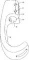
根据本发明的另一特征,增强了该高性能假足在各种活动期间吸收和恢复垂直负载或垂直冲击力的能力,其中,足龙骨件的向上拱起的中间部分设有弹簧,其在假足的使用期间可被压缩以吸收垂直负载,以及伸展开以恢复垂直负载。在示例性实施例中,该足龙骨件的拱形中间部分的后端向下且向前地卷绕而形成了弹簧。足龙骨件的后足部分通过该弹簧而连接到中间部分上。在假足的垂直加载期间,不仅通过伸展中间部分的拱形长度,而且还通过压缩弹簧来弹性加载式地储存能量。当作用于假足上的垂直方向上的力降低时,中间部分所储存的能量恢复。在垂直力可从低至三倍体重到高至十三倍体重而变化的从步行到跑步及跳跃的活动范围内,可以保持假足的适当功能而不会损坏。According to another feature of the present invention, the ability of the high performance prosthetic foot to absorb and recover vertical loads or vertical impact forces during various activities is enhanced, wherein the upwardly arched mid-section of the foot keel is provided with a spring that During use the prosthetic foot can be compressed to absorb vertical loads and expanded to recover vertical loads. In an exemplary embodiment, the rear end of the arched mid-section of the foot keel coils downwardly and forwardly to form a spring. The rear foot portion of the foot keel is connected to the mid portion by the spring. During vertical loading of the prosthetic foot, energy is stored elastically, not only by extending the arched length of the middle part, but also by compressing the spring. When the force in the vertical direction on the prosthetic foot is reduced, the energy stored in the mid-section is restored. Proper function of the prosthetic foot can be maintained without damage over a range of motion from walking to running and jumping where vertical forces can vary from as low as three times body weight to as high as thirteen times body weight.
通过对本发明的所公开示例性实施例的详细描述并参照附图,可以更加清楚本发明的这些和其它的目的、特征及优点。These and other objects, features and advantages of the present invention will become more apparent from the detailed description of the disclosed exemplary embodiments of the present invention with reference to the accompanying drawings.
附图说明Description of drawings
图1是示意性图示,显示了本发明假足的足龙骨件和小腿胫骨件的两个相邻并相互靠着的曲率半径R1和R2,其在步态中产生了该足在箭头B方向上的动态响应能力和运动输出,该箭头B的方向垂直于连接两个半径的切线A。Figure 1 is a schematic illustration showing two adjacent and mutually abutting radii of curvatureR1 andR2 of the foot keel and calf shank of the prosthetic foot of the present invention, which produce the foot in gait. Dynamic responsiveness and motion output in the direction of arrow B, which is perpendicular to the tangent A connecting the two radii.
图2是类似于图1的视图,但是显示了这两个半径的定位在根据本发明的假足中已发生变化,以提高该足在步态中的动态响应能力和运动输出的水平分量而降低其垂直分量,因此,垂直于切线A1的箭头B1比图1所示的情形更朝向水平。Figure 2 is a view similar to Figure 1 but showing that the positioning of these two radii has been changed in a prosthetic foot according to the invention to improve the dynamic responsiveness of the foot in gait and the horizontal component of motor output Its vertical component is reduced, so that the arrow B1 perpendicular to the tangent A1 is more horizontal than in the case shown in FIG. 1 .
图3是根据本发明一个示例性实施例的假足的侧视图,其具有用于将假足紧固到截肢者下肢上的暂用假肢转接器和与之相连的暂用假肢。3 is a side view of a prosthetic foot having a temporary prosthesis adapter and a temporary prosthesis attached thereto for securing the prosthetic foot to the lower limb of an amputee, according to an exemplary embodiment of the present invention.
图4是带有图3所示的暂用假肢转接器和暂用假肢的假足的正视图。FIG. 4 is a front view of the prosthetic foot with the temporary prosthetic adapter and temporary prosthesis shown in FIG. 3 .
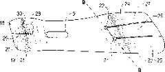
图5是图3和4所示实施例的顶视图。FIG. 5 is a top view of the embodiment shown in FIGS. 3 and 4. FIG.
图6是本发明的尤其用于短跑的另一足龙骨件的侧视图,其可应用在本发明的假足中。Figure 6 is a side view of another foot keel of the present invention, particularly for sprinting, which may be used in the prosthetic foot of the present invention.
图7是图6所示足龙骨件的顶视图。FIG. 7 is a top view of the foot keel shown in FIG. 6. FIG.
图8是图3所示假足中的足龙骨件的底视图,其提供了高、低动态响应特性和双平面运动性能。Fig. 8 is a bottom view of the foot keel in the prosthetic foot shown in Fig. 3, which provides high and low dynamic response characteristics and biplane motion performance.
图9是用于假足的本发明另一足龙骨件的侧视图,其尤其适用于做过足Symes切断术的截肢者进行短跑。Fig. 9 is a side view of another foot keel of the present invention for use in a prosthetic foot, especially for sprinting by an amputee who has had a Symesotomy of the foot.
图10是图9所示足龙骨件的顶视图。Figure 10 is a top view of the foot keel shown in Figure 9 .
图11是用于Symes截肢者的本发明假足的足龙骨件的另一变型,该足龙骨件为假足提供了高、低动态响应特性以及双平面运动性能。Fig. 11 is another variation of the foot keel of the prosthetic foot of the present invention for the Symes amputee, which provides high and low dynamic response characteristics and biplane motion performance to the prosthetic foot.
图12是图11所示足龙骨件的顶视图。FIG. 12 is a top view of the foot keel shown in FIG. 11. FIG.
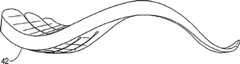
图13是本发明足龙骨件的侧视图,其中龙骨件的厚度从其中足部分到后足部分变细,例如逐渐减小。13 is a side view of a foot keel of the present invention wherein the thickness of the keel tapers, eg, tapers, from the midfoot portion to the rearfoot portion.
图14是足龙骨件的另一形式的侧视图,其中该厚度从龙骨件的中足朝向前足和后足均变细。Figure 14 is a side view of another version of the foot keel in which the thickness tapers from the midfoot of the keel towards both the forefoot and the rearfoot.
图15是本发明假足的抛物线形小腿胫骨件的从稍上方到正面看去的侧视图,小腿胫骨件的厚度朝向其上端变细。Figure 15 is a side view from slightly above to the front of the parabolic calf shank of the prosthetic foot of the present invention, the thickness of the calf shank tapering towards its upper end.
图16是与图15类似的侧视图,但显示了从中间朝向其上端和下端均变细的另一小腿胫骨件。Figure 16 is a side view similar to Figure 15 but showing another calf shank tapering from the middle towards both its superior and inferior ends.
图17是用于假足的C形小腿胫骨件的侧视图,该小腿胫骨件的厚度从中间朝向其上端和下端变细。Figure 17 is a side view of a C-shaped calf shank for a prosthetic foot, the thickness of which tapers from the middle towards its upper and lower ends.
图18是用于假足的C形小腿胫骨件的另一实例的侧视图,该小腿胫骨件的厚度从其中间部分到其上端逐渐减小。18 is a side view of another example of a C-shaped calf shank for a prosthetic foot, the calf shank gradually decreasing in thickness from its middle portion to its upper end.
图19是用于假足的S形小腿胫骨件的侧视图,其厚度从其中间到两个端部逐渐减小。Fig. 19 is a side view of an S-shaped calf shank for a prosthetic foot, the thickness of which gradually decreases from its middle to both ends.
图20是S形小腿胫骨件的另一实例,其厚度仅在其上端处变细。Figure 20 is another example of an S-shaped calf shank that tapers in thickness only at its upper end.
图21是用于本发明假足的在各端处变细的J形小腿胫骨件的侧视图。Figure 21 is a side view of a J-shaped calf shank tapered at each end for a prosthetic foot of the present invention.
图22是与图21类似的视图,但是显示了在厚度上仅朝向其上端逐渐减小的J形小腿胫骨件。Figure 22 is a view similar to Figure 21 but showing a J-shaped calf shank that only tapers in thickness toward its upper end.
图23是从稍上方看去的铝制或塑料连接件的侧视图,其用在如图3所示地将小腿胫骨件连接到足龙骨件上的本发明的可调紧固装置中。Figure 23 is a side view from slightly above of an aluminum or plastic connector used in the adjustable fastening device of the present invention connecting the calf shank to the foot keel as shown in Figure 3 .
图24是应用在图3-5所示假足上的暂用假肢转接器的从侧面和稍靠正面看去的视图,该转接器还可用于将足连接到附在截肢者腿上的暂用假肢上。Figure 24 is a side and slightly frontal view of a temporary prosthetic adapter applied to the prosthetic foot shown in Figures 3-5, which adapter can also be used to attach the foot to an amputee's leg temporary prosthetics.
图25是与图3所示类似的本发明另一假足的侧视图,但其显示了带有两个纵向隔开的可松开紧固件的连接件,这两个紧固件分别将连接件连接到小腿胫骨件和足龙骨件上。Figure 25 is a side view of another prosthetic foot of the present invention similar to that shown in Figure 3, but showing an attachment with two longitudinally spaced releasable The link connects to the calf shank and the foot keel.
图26是图25所示连接件的放大侧视图。Fig. 26 is an enlarged side view of the connector shown in Fig. 25 .
图27是图25所示假足的小腿胫骨件的放大侧视图。27 is an enlarged side view of the calf shank of the prosthetic foot shown in FIG. 25. FIG.
图28是本发明另一实施例的假足的后视图,其中,足龙骨件的拱形中间部分的后端形成有弹簧,其可在假足的多种应用期间被压缩以吸收垂直负载,并且伸展开以恢复垂直负载。28 is a rear view of a prosthetic foot according to another embodiment of the present invention, wherein the rear end of the arched mid-section of the foot keel is formed with a spring that can be compressed to absorb vertical loads during various applications of the prosthetic foot, And stretch out to recover the vertical load.
图29是图28所示假足的侧视图,其显示了连接到足龙骨件的朝上拱起的中间部分的后表面上的小腿胫骨件。29 is a side view of the prosthetic foot shown in FIG. 28 showing the calf shank attached to the posterior surface of the upwardly arched medial portion of the foot keel.
图30是图28和29所示假足的正视图。Figure 30 is a front view of the prosthetic foot shown in Figures 28 and 29.
图31是图28-30所示假足的足龙骨件的仰视图。Figure 31 is a bottom view of the foot keel of the prosthetic foot shown in Figures 28-30.
图32是图28-30所示假足的俯视图。Figure 32 is a top view of the prosthetic foot shown in Figures 28-30.
图33是类似于图28-32所示的本发明假足的另一形式的侧视图,不同之处在于,假足的足龙骨件具有安装到拱形中间部分的后端背面上的配件,以用于将假足的足龙骨件直接连接到附在使用者腿残端上的支承结构上。Figure 33 is a side view of another version of the prosthetic foot of the present invention similar to that shown in Figures 28-32, except that the foot keel of the prosthetic foot has fittings attached to the back end of the arched midsection, For connecting the foot keel of the prosthetic foot directly to a support structure attached to the user's leg stump.
图34是图33所示假足的俯视图。Fig. 34 is a top view of the prosthetic foot shown in Fig. 33 .
实施本发明的最佳方式Best Mode for Carrying Out the Invention
下面来看附图,从图3到5中的示例性实施例中可以看到,假足1包括纵向延伸的足龙骨件2,该足龙骨件2具有位于一端的前足部分3、位于另一端的后足部分4,以及在前足和后足部分之间延伸的向上拱起的中足部分5。在该示例性实施例中,中足部分5在前足和后足部分之间在其整个纵向范围上向上凸出式弯曲。Turning now to the drawings, it can be seen from the exemplary embodiment in FIGS. 3 to 5 that a
足1的直立小腿胫骨件6通过可松开的紧固件8和连接件11而在其向下凸出的弯曲下端7的一部分处连接到龙骨件中足部分5的贴近的后表面上。在该示例性实施例中,紧固件8是带有螺母和垫圈的单个螺栓,然而它也可以是可松开的压板或其它紧固件,用来在紧固件拧紧时将小腿胫骨件可靠地定位和保持在足龙骨件上。
参见图8,在龙骨件中足部分5的贴近后表面上形成有纵向延伸的开口9。在小腿胫骨件6的弯曲下端7内也形成有例如图15所示的纵向延伸的开口10。可松开的紧固件8延伸穿过开口9和10,这样,在将紧固件8松开或释放时便可在图5中A-A所示的纵向上调整小腿胫骨件和足龙骨件相互之间的定位,从而根据特定的任务来调节假足的性能。这样,紧固件8、连接件11以及纵向延伸的开口9和10构成了用于将小腿胫骨件连接到足龙骨件上以形成假足的踝关节区域的可调紧固装置。Referring to FIG. 8, a
从图1和2中可以看到调整小腿胫骨件6和足龙骨件2的定位的效果,其中两个相互紧邻的半径R1和R2代表足龙骨件中间部分5和小腿胫骨件6的相邻且相互面对的拱形或凸出的曲面。当把两个这种半径看作相互紧邻时,在与画在两个半径之间的图1所示切线A和图2所示切线A1垂直的方向上存在运动能力。这两个半径之间的相互关系决定了运动输出的方向。结果,足1的动态响应力的施加取决于这种关系。凹面的半径越大,动态响应能力就越强。然而,半径越小,响应就越快。The effect of adjusting the positioning of the
本发明假足中的小腿胫骨件和足龙骨件的定位能力可允许半径移动,因此可在体育运动中对足的水平或垂直线速度施加影响。例如,为了增强假足1的水平线速度能力,可进行定位变更以影响小腿胫骨件半径和足龙骨件半径的关系。也就是说,为了增强水平线速度特性,如对比图2和图1所显示的那样,足龙骨件的底部半径R2比其起始位置更靠近远端。这就将足1的动态响应特性和运动输出改变成更靠近水平方向,从而可通过相同的施加力来获得更大的水平线速度。The positioning capabilities of the calf shank and foot keel in the prosthetic foot of the present invention allow for radial movement, thereby influencing the horizontal or vertical linear velocity of the foot during athletic movement. For example, to enhance the horizontal linear velocity capability of the
当截肢者的需求涉及到水平和垂直的线速度时,他/她可通过实践来找到能满足其需求的用于各种运动的设置。例如,跳高运动员和篮球运动员比短跑运动员需要更多的垂直升程。连接件11是夹在相连的足龙骨件2和小腿胫骨件6之间的塑料或铝制的定位连接件(参见图3、4和23)。可松开的紧固件8延伸穿过连接件中的孔12。连接件沿小腿胫骨件和龙骨件中足部分5的贴近后表面的相连部分而延伸。As the amputee's needs relate to horizontal and vertical linear velocities, he or she can use practice to find settings for various movements that meet his or her needs. For example, high jumpers and basketball players require more vertical lift than sprinters.
小腿胫骨件6的弯曲下端7为抛物线形,该抛物线的最小曲率半径位于下端,并且以抛物线形最初向前、然后向上延伸。如图3所示,小腿胫骨件的曲率形成了向后的凹度。抛物线形状是有利的,因为它具有增强的动态响应特性,产生了与其相对更大半径的近端相关联的提高的水平线速度,同时在其下端具有更小的曲率半径,以实现更快的响应特性。抛物线形状的上端处的更大曲率半径使得参见图1和2来介绍的切线A在定位变化中保持为更加垂直地定向,这可以产生提高的水平线速度。The curved
在小腿胫骨件6的上端通过紧固件14连接了暂用假肢转接器13。转接器13又通过紧固件16紧固到暂用假肢15的下端上。暂用假肢15通过连接到腿残端上的支承结构(未示出)而紧固到截肢者的下肢上。A temporary
在该示例性实施例中,足龙骨件2的前足、中足和后足部分由单件弹性材料形成。例如,可以采用本质上为塑性的材料实心件,其在被地面反作用力偏转时具有形状保持特性。尤其是可采用与热固性环氧树脂层压在一起的高强度石墨或商品名称为Delran的挤压塑料或脱气的聚氨酯共聚物来形成足龙骨件以及小腿胫骨件。与这些材料相关的功能性质提供了具有较低重量和最小蠕变的高强度。利用假体工业标准在真空下来层压热固性环氧树脂。可将聚氨酯共聚物浇注到阴模中,并对挤压塑料进行机加工。每种材料的使用都具有其优点和缺点。In the exemplary embodiment, the forefoot, midfoot and rearfoot portions of
弹性材料的例如涉及刚度、挠度和强度的物理性质全部由材料的厚度决定。较薄材料比同样密度的较厚材料更容易偏转。所采用的材料及物理性能与假足龙骨件和小腿胫骨件的刚度和挠度特性相关。在图3到5所示的示例性实施例中,足龙骨件和小腿胫骨件的厚度是均匀的或对称的,但是,厚度可在这些部件的长度上以下面将讨论的方式变化,例如可使后足和前足区域更薄一些,并且对中足区域的偏转更敏感。Physical properties of elastic materials, such as those relating to stiffness, deflection, and strength, are all determined by the thickness of the material. Thinner material deflects more easily than thicker material of the same density. The materials used and their physical properties are related to the stiffness and deflection characteristics of the prosthetic foot keel and calf shank. In the exemplary embodiment shown in Figures 3 to 5, the thickness of the foot keel and calf shank is uniform or symmetrical, however, the thickness may vary over the length of these components in the manner discussed below, for example Made the rearfoot and forefoot areas a bit thinner and more responsive to deflection in the midfoot area.
为了帮助向假足1提供高、低动态响应能力,将中足部分5形成为纵向的拱形,使得纵向拱形的内侧比纵向拱形的外侧具有相对更高的动态响应能力。为此,在该示例性实施例中,纵向拱形的凹面的内侧在半径上比其外侧更大。后足部分4的后端17成形为向上弯曲的拱形,可在脚跟冲击期间通过压缩减震来对地面反作用力作出反应。后足部分4所形成的脚跟形成有后外角部18,该角部18比内侧角部19更靠后侧和更靠外侧,以促进后足在步态的初始接触阶段中进行外翻。前足部分3的前端20成形为向上弯曲的拱形,以模拟在步态最后站立阶段中的脚跟抬起脚趾离地位置中处于背屈状态下的人脚趾。在前足和后足的下部设有作为缓冲垫的橡胶或泡沫衬垫53和54。To help provide high and low dynamic responsiveness to the
在前足部分3的背面和足底面之间延伸穿过前足部分3的内侧伸展接合孔21和外侧伸展接合孔22产生了假足的增强的双平面运动能力。伸展连接部分23和24从相应孔中向前延伸到前足部分的前边沿,以形成内侧、中部和外侧的伸展支撑25、26和27,其带来了足龙骨件的前足部分的增强的双平面运动能力。伸展接合孔21和22沿图5中的线B-B设置在相对于足龙骨件纵向轴线A-A成350的α角延伸的横向平面内,其中内侧伸展接合孔21比外侧伸展接合孔22更靠前。投射在矢状面上的伸展接合孔21和22相对于横向平面倾斜成450角,其中孔的背面比足底面更靠前。采用这种设置,从可松开的紧固件8到外侧伸展接合孔22的距离比从可松开的紧固件到内侧伸展接合孔21的距离更短,使得假足1的外侧部分比内侧具有更短的脚趾杠杆(toe lever),以实现中足的高和低的动态响应。The medial
足龙骨件2的后足部分4的前部还包括在后足部分4的背面和足底面之间延伸穿过后足部分4的伸展接合孔28。伸展连接部分29从孔28中向后延伸到后足部分的后边沿,以形成伸展支撑30和31。这样就为假足的后足部分带来了增强的双平面运动能力。The front portion of the
如图3所示,足龙骨件2的中足部分5和前足部分3的背面形成了朝上的凹面32,使得它能够在功能上模仿人足的第五趾运动轴线。也就是说,凹面32具有定位成相对于足龙骨件纵向轴线A-A成20°到35°的角13的纵向轴线C-C,其中,内侧比外侧更靠前,以便促进步态的第五趾运动,如同在人足中的第二到第五趾骨的旋转的倾斜的低速档旋转轴线中一样。As shown in Figure 3, the backside of the
当截肢者在不平的地势上行走或运动员在足上向内或向外急停时,便可理解到双平面运动能力的重要性。地面作用力矢量的方向从矢状定位改变到具有额平面分量。地面将在与足向外作用相反的方向上向内作用。结果,小腿胫骨件向内侧倾斜,并且重力施加到足龙骨件的内侧结构上。响应于这些压力,足龙骨件2的内侧伸展连接支撑25和31背屈(向上偏转)并内翻,而外侧伸展连接支撑27和30足底屈曲(向下偏转)并外翻。这一运动用来将脚掌的足底面放在地面上(足底触地)。The importance of biplanar mobility is understood when an amputee walks on uneven terrain or when an athlete stops sharply in or out on the foot. The direction of the ground force vector changes from a sagittal orientation to have a frontal plane component. The ground will act inward in the opposite direction to the outward action of the foot. As a result, the calf shank tilts medially and gravity is applied to the medial structure of the foot keel. In response to these pressures, medial extension link struts 25 and 31 of
参见图6和7,在本发明的假足中可以使用本发明的另一足龙骨件33,其尤其适用于短跑。在短跑中,身体的重心变成基本上仅沿矢状面定位。假足不需要具有低动态响应特性。结果,不需要象在足龙骨件2中那样使前足、中足凹面的纵向轴线定位在35°的外部旋转方位上。相反,如在图6和7中所示,凹面的纵向轴线D-D的方位应当变成与额平面平行。这就使得短跑足仅在矢状方向作出反应。另外,前足和中足部分中的伸展接合孔34和35的方位沿着线E-E平行于额平面,即外侧孔35向前移动到与内侧孔34成一直线,并平行于额平面。足龙骨件33的前末端36也制成为与额平面平行。足龙骨件的后末端脚跟区域37也平行于额平面。这些修改会对假足的多用途性能带来不利影响。然而,它的性能特征是针对特定任务的。短跑足龙骨件33的另一个变型在该假足的前足部分的脚趾区域中,其中将足龙骨件2中的15°背屈增大为足龙骨件33中的25-40°背屈。Referring to Figures 6 and 7, another
图9和10显示了本发明的另一足龙骨件38,它可用在尤其适用于做过Symes切断术的截肢者进行短跑的假足中。为此,足龙骨件38的中足部分包括靠后的向上凹面39,其中可通过可松开的紧固件来将小腿胫骨件的弯曲下端连接到足龙骨件上。所有的下肢截肢者都可采用这种足龙骨件。足龙骨件38可适用于与Symes级截肢者相关的较长余肢。它的性能特征在动态响应性能方面快得多。它的应用并不专门用于这种程度的截肢。可将其应用在所有穿过胫骨和穿过股骨的截肢状况中。在图11和12的示例性实施例中,足龙骨件40还具有用于Symes截肢者的凹面41,该足龙骨件向假足提供了与图3-5和8所示示例性实施例中的相似的高、低动态响应特性,以及双平面运动性能。Figures 9 and 10 illustrate another
用于假足1的几个足龙骨件的功能特征与形状和设计特征相关,它们涉及到凹面、凸面、半径大小、伸展、压缩以及材料的物理性能,所有这些性质涉及到对行走、跑步和跳跃活动中的地面作用力作出反应。The functional characteristics of the several foot keels used in the
图13中的足龙骨件42与图3-5和8所示示例性实施例中的相类似,不同之处在于,足龙骨件的厚度从中足部分朝向后足的后部变细。图14中的足龙骨件43的厚度在其前端和后端处逐渐减小或变细。图14中的小腿胫骨件44和图16中的小腿胫骨件45显示了厚度上的类似变化,它们都可以用在假足1中。足龙骨件和小腿胫骨件的每一项设计都会产生不同的功能输出,这是因为这些功能输出涉及到水平和垂直的线速度,而这些速度在不同的运动任务中对于提高性能来说是特定的。多种小腿胫骨件结构以及足龙骨件和小腿胫骨件之间的设置调整的能力产生了假足小腿胫骨件的关系,该关系使得截肢者和/或修复学家具备在各种各样的体育和休闲活动中的一种选出活动中将假足调节到最高性能的能力。The
在图17-22中显示了用于假足1的其它小腿胫骨件,包括C形小腿胫骨件46和47,S形小腿胫骨件48和49,以及J形小腿胫骨件50和51。小腿胫骨件的上端还可包括笔直的垂直端,其带有连接到该最近末端上的棱形连板。可将公锥形螺栓(male pyramid)穿过该小腿胫骨件的垂直端而形成螺栓接合。还可在小腿胫骨件的近端和远端处的延伸开口内设置用来接受相邻公锥形螺栓和远端足龙骨件的塑料或铝填充物。本发明的假足是优选由标准化的单元或尺寸构造成的模块化系统,以便满足使用中的灵活性和多样性。Other calf shanks for the
所有与轨道相关的赛跑运动都是以逆时针方向进行的。本发明的另一可选特征考虑到了作用在沿着这种弯曲路径前进的足上的力。当物体沿弯曲路径运动时,向心加速度朝向旋转中心起作用。牛顿第三定律适合于能量作用。存在有相等且相反的反作用力。因此,对每一“向心”力来说,都存在有一个“离心”力。向心力朝向旋转中心作用,而离心力即反作用力远离旋转中心作用。当运动员在跑道上围绕曲线跑步时,向心力会将跑步者拉向曲线的中心,而离心力会将跑步者拉离曲线的中心。为了抵消试图让跑步者向外倾斜的离心力,跑步者要向内倾斜。如果跑步者在跑道上的旋转方向一直是逆时针的,则左侧是跑道的内侧。结果,根据本发明的特征,可将左、右假足小腿胫骨件的左侧制成为比右侧更厚,以增强截肢跑步者的曲线性能。All track-related running movements are performed in a counterclockwise direction. Another optional feature of the invention takes into account the forces acting on a foot advancing along such a curved path. When an object moves along a curved path, centripetal acceleration acts toward the center of rotation. Newton's third law applies to the action of energy. There are equal and opposite reaction forces. Therefore, for every "centripetal" force, there exists a "centrifugal" force. Centripetal force acts towards the center of rotation, while centrifugal force, the reaction force, acts away from the center of rotation. When an athlete runs around a curve on a track, centripetal force pulls the runner toward the center of the curve, while centrifugal force pulls the runner away from the center of the curve. To counteract the centrifugal force trying to tip the runner out, the runner leans in. If the runner's rotation is always counterclockwise on the track, the left side is the inside of the track. As a result, the left and right prosthetic foot calf shanks can be made thicker on the left side than the right side in accordance with features of the present invention to enhance curve performance in amputee runners.
在若干实施例中,足龙骨件2,33,38,42和43均是29厘米长,其与鞋子1的长度成一定比例,并且在图3、4和5以及不同小腿胫骨件和足龙骨件的若干视图中按比例示出。然而,本领域的普通技术人员容易理解,假足的具体尺寸可根据要配备此足的截肢者的大小、重量和其它特征的情况而变。In several embodiments, the foot keels 2, 33, 38, 42 and 43 are each 29 centimeters long, which is proportional to the length of the
下面来看假足1在行走和跑步站立阶段的步态周期内的工作情况。牛顿的涉及到惯性、加速度以及作用力与反作用力的运动三定律是足2的运动学基础。从牛顿第三定律即作用力与反作用力定律中已知,地面对足的作用力与足对地面的作用力方向相等且大小相反。它们称为地面反作用力。关于人的步态、跑步以及跳跃活动已经进行了许多科学研究。测力板的研究表明,在步态中遵循牛顿第三定律。从这些研究中可以知道地面对足的作用力的方向。Let's look at how the
可将行走/跑步活动的站立阶段进一步分解成减速和加速阶段。当假足接触地面时,足在地面上向前施加力,地面以相等且方向相反的方式进行反作用,也就是说,地面对假足向后施加作用。这一作用力使假足运动。行走和跑步活动的站立阶段分析从图3和18中的后外角部18成为接触点开始,其比足的内侧更向后和向外偏移。在初始接触时,这种偏移导致足向外翻,而小腿胫骨件向足底屈曲。小腿胫骨件总是在寻找可通过其胫骨来传递体重的位置,例如,其倾向于将其较长的垂直件置于可抵抗地面作用力的位置。这就是为何它使向后的足底屈曲移动到可抵抗向后作用在足上的地面反作用力。地面作用力导致小腿胫骨件压缩,并且其近端向后移动。小腿胫骨件的较小半径压缩,以模拟人的踝关节足底屈曲,通过压缩来将前足放在地面上。同时,足龙骨件2的顶部后侧通过压缩而向上压。这两种压缩作用力起作吸震的作用。一旦小腿胫骨件停止运动到足底屈曲中并且地面对足向后施加作用,那么后外侧脚跟18的偏移可进一步增强这种吸震作用,该偏移会导致足外翻,也起到吸震的作用。The stance phase of the walking/running activity can be further broken down into deceleration and acceleration phases. When the prosthetic foot contacts the ground, the foot exerts a force forward on the ground, and the ground reacts in an equal and opposite manner, that is, the ground acts on the prosthetic foot backwards. This force moves the prosthetic foot. The stance phase analysis of walking and running activities begins with the posterior
然后,足龙骨件和小腿胫骨件的已压缩件开始卸载,即它们设法回到其初始形状并释放掉所储存的能量,这导致小腿胫骨件的近端以加速的方式向前移动。当小腿胫骨件接近其垂直的初始位置时,地面作用力由对足向后作用改变为对足垂直向上作用。由于假足具有后侧和前侧足底面承重区域,并且它们由非承重的长拱形中间部分相连,因此来自假肢的垂直方向的作用力促使该长拱形的中间部分通过伸展来承受负载。后侧和前侧承重表面是分开的。由于地面作用力在性质上从垂直地转变成朝向前侧,因此这些垂直方向的作用力储存在足的长拱形中间部分内。小腿胫骨件可伸展,以模拟踝的背屈。这会导致假足枢轴转动而离开前侧足底承重表面。后足的长拱形从压缩态变化到伸展态。这就将所储存的垂直压缩力能量释放出来,以增强伸展性能。The compressed members of the foot keel and calf shank then begin to unload, ie they try to return to their original shape and release the stored energy, which causes the proximal end of the calf shank to move forward in an accelerated manner. As the calf shank approaches its vertical initial position, the ground force changes from acting posteriorly on the foot to acting vertically upward on the foot. Since the prosthetic foot has posterior and anterior plantar weight-bearing areas, and they are connected by a non-weight-bearing long-arched midsection, vertical forces from the prosthesis cause the long-arched midsection to take the load by stretching. The rear and front load-bearing surfaces are separate. Since the nature of ground forces transitions from vertical to forward, these vertical forces are stored within the long arched medial portion of the foot. The calf shank extends to simulate dorsiflexion of the ankle. This causes the prosthetic foot to pivot away from the anterior plantar weight-bearing surface. The long arch of the rear foot changes from compression to extension. This releases stored vertical compressive energy for enhanced stretch performance.
足龙骨件和小腿胫骨件的长拱形会阻碍它们各自结构的伸展。结果,小腿胫骨件的向前运动被阻止,足就开始枢轴转动而离开前侧足底承重表面。在图3-5和8、图11和12、图13和图14的示例性实施例所示的足龙骨件中,足龙骨件的中足部分的伸展具有高、低响应能力。由于这些足龙骨件的中足与前足过渡区域从足纵轴线向外偏离25°到35°,因此内侧长拱形部分比外侧长拱形部分更长。这是很重要的,因为在正常的足中,足的内侧在加速或减速期间要被用到。The long arches of the foot keel and calf shank impede the extension of their respective structures. As a result, forward movement of the calf shank is prevented and the foot begins to pivot away from the anterior plantar weight bearing surface. In the foot keels shown in the exemplary embodiments of Figures 3-5 and 8, Figures 11 and 12, Figures 13 and 14, the extension of the midfoot portion of the foot keel has high and low responsiveness. Because the midfoot to forefoot transition area of these foot keels is offset 25° to 35° outward from the longitudinal axis of the foot, the medial elongated arch portion is longer than the lateral elongated arch portion. This is important because in a normal foot the medial side of the foot is used during acceleration or deceleration.
假足的更长内侧拱形具有比外侧更大的动态响应特性。在慢速的行走或跑步中采用了外侧更短的脚趾杠杆。身体的重心以正弦曲线在空间中运动。它向内侧、外侧、近端和远端运动。在慢速地行走或跑步时,身体的重心比在快速行走或跑步时更向内侧和外侧运动。此外,动量或惯性更小,并且克服更高动态响应能力的能力更小。本发明的假足适合于适应这些应用力学中的原理。The longer medial arch of the prosthetic foot has greater dynamic response properties than the lateral. Outer shorter toe levers are used for slow walking or running. The center of gravity of the body moves in space in a sinusoidal curve. It moves medially, laterally, proximally and distally. When walking or running slowly, the body's center of gravity moves more inward and outward than when walking or running fast. Additionally, there is less momentum or inertia and less ability to overcome higher dynamic responsiveness. The prosthetic foot of the present invention is adapted to accommodate these principles in applied mechanics.
当地面作用力在假足上向前施加作用且假足在地面上被向后施加作用时,由于脚跟开始提升,因此中足部分的长拱形的前部的轮廓形成为可垂直于其足底面来施加这些朝后的作用力。这是施加这些作用力的最有效和最有效率的方法。关于假足的后侧后足部分存在相同的情况。它还成形为使得在初始接触时的向后地面作用力与足龙骨件的垂直其施力方向的足底面相反。As ground forces act forward on the prosthetic foot and the prosthetic foot is acted backward on the ground, the long arched front of the midfoot portion is contoured to be perpendicular to its foot as the heel begins to lift. bottom surface to apply these rearward forces. This is the most effective and efficient method of applying these forces. The same holds true for the posterior hindfoot portion of the prosthetic foot. It is also shaped so that the rearward ground force at initial contact is opposed to the plantar surface of the foot keel perpendicular to its direction of force application.
在脚跟提升、脚趾离地的行走和跑步活动的随后阶段中,前足部分的趾区域产生15°-35°的背屈。这种向上延伸的弓形允许向前地面作用力来压缩足的该区域。这种压缩比伸展受到更少的阻力,并且在假足的步态和跑步的摇摆阶段中实现平稳的过渡。在步态站立阶段的随后过程中,伸展的小腿胫骨件和伸展的中足长拱形部分将它们所储存的能量释放出来,以促进截肢者的身体重心的推进。During the subsequent phases of heel-lift, toe-off walking and running activities, a dorsiflexion of 15°-35° occurs in the toe region of the forefoot portion. This upwardly extending arch allows force toward the ground to compress this area of the foot. This compression experiences less resistance than extension and enables a smooth transition between the prosthetic foot's gait and the swing phase of running. During the subsequent stance phase of gait, the extended calf shank and extended midfoot long arch release their stored energy to facilitate propulsion of the amputee's body center of gravity.
在前面提到的几个实施例中,足龙骨件的后足和前足区域的后部结合有伸展接合孔和伸展接合支撑。当在不平坦的地势上行走时,伸展接合孔的方位起到斜接铰链的作用,增强了双平面运动性能,以便改善足底面的整体接触特性。In several of the aforementioned embodiments, the rear of the foot keel and the rear of the forefoot region incorporate expansion engagement holes and expansion engagement supports. When walking on uneven terrain, the orientation of the stretch articulation holes acts as a mitered hinge, enhancing bi-plane motion for improved overall contact characteristics on the plantar surface of the foot.
图9-12中的Symes足龙骨件在动态响应性能方面是显著不同的,这是因为这些性能与行走、跑步和跳跃活动相关。这些足龙骨件在四个显著特征上不同。这些情况包括在中足部分的贴近后部中存在有凹面,其可比平坦表面更好地适应Symes远端残肢形状。定位凹面要求拱形足龙骨件的中间部分的对应前侧和后侧半径更具活动性,并且尺寸更小。结果,所有中足长拱形半径和后足半径都是更密且更小的。这会显著地影响动态响应特性。更小的半径导致更小的动态响应。然而,假足对所有上述行走、跑步和跳跃的地面作用力的响应更快。结果是具有更小动态响应的更快的足。The Symes foot keels in Figures 9-12 are significantly different in terms of dynamic response properties as these properties relate to walking, running and jumping activities. These foot keels differ in four notable features. These include the presence of a concavity in the proximal portion of the midfoot portion that conforms to the shape of Symes' distal stump better than a flat surface. Locating the concavity requires that the corresponding anterior and posterior radii of the medial portion of the arched foot keel be more mobile and smaller in size. As a result, all midfoot long arch radii and rearfoot radii are denser and smaller. This significantly affects the dynamic response characteristics. A smaller radius results in less dynamic response. However, the prosthetic foot responds more quickly to all of the aforementioned ground forces of walking, running, and jumping. The result is a faster foot with less dynamic response.
采用本发明的假足便可通过定位变更来实现增强的任务特定型运动性能,这是因为这些定位变更会影响各任务的垂直和水平分量。人足是多功能的单元,其可行走、跑步和跳跃。另一方面,人的胫腓骨小腿胫骨结构不是多功能的单元。它是可在行走、跑步和跳跃活动中平行于其较长的近端-远端方位施加其作用力的简单杠杆。它是不可压缩的结构,并且不能储存能量。另一方面,本发明的假足具有动态响应能力,这是因为这些动态响应能力与运动员的行走、跑步和跳跃活动的水平和垂直线速度分量相关,并且优于人的胫骨和腓骨。结果就可以增强截肢者的运动性能。为此,根据本发明,可松开紧固件8并沿足龙骨件的纵向来调整小腿胫骨件和足龙骨件相互之间的定位。在图1和2中显示了这种变化。然后,在调整后的位置上用紧固件8将小腿胫骨件紧固到足龙骨件上。在调整期间,紧固件8的螺栓可相对于分别位于足龙骨件和小腿胫骨件内的相对且较长的纵向延伸开口9和10中的一个或两个滑动。The use of the prosthetic foot of the present invention enables enhanced task-specific locomotor performance through positioning changes that affect the vertical and horizontal components of each task. The human foot is a multifunctional unit that can walk, run and jump. On the other hand, the human tibiofibular tibial structure is not a multifunctional unit. It is a simple lever that exerts its force parallel to its longer proximal-distal orientation during walking, running and jumping activities. It is an incompressible structure and cannot store energy. On the other hand, the prosthetic foot of the present invention has dynamic responsiveness because these dynamic responsiveness is related to the horizontal and vertical linear velocity components of the athlete's walking, running and jumping activities, and is superior to the human tibia and fibula. As a result, the motor performance of amputees can be enhanced. To this end, according to the invention, the
增强了跑步者的性能特征的定位变更是一种足龙骨件相对于小腿胫骨件向前滑动且足底在小腿胫骨件上屈曲的定位变更,其中跑步者以脚掌来与地面进行初始接触,如短跑者一样。这种新的关系提高了跑步的水平分量。换句话说,由于小腿胫骨件的底面向足屈曲,并且与最初的脚跟接触相反,足以脚掌着地的位置与地面接触,因此地面会直接向后对足施加作用,而足会向前对地面施加作用。这会使得小腿胫骨件向前(通过伸展)和向下快速运动。通过会阻碍小腿胫骨件的初始运动方向的伸展而产生了动态响应力。结果,足就在趾骨足底面承重区域上枢轴转动。这会导致龙骨件的中足区域伸展,该伸展比压缩受到的更大阻碍。小腿胫骨件的伸展和中足的伸展的总效应是小腿胫骨件的进一步向前运动受到阻碍,这便允许使用者体内的膝伸展结构和臀伸展结构以更有效的方式向前和朝向近端来移动身体的重心(即水平速度增加)。在这种情况下,与跟趾跑步者相比,重心更向前而非更向上,跟趾跑步者的小腿胫骨件的向前运动受到小腿胫骨件的更少阻碍,并且开始受到比脚掌着地跑步者更多的背屈(垂直的)。An alignment change that enhances a runner's performance characteristics is one in which the foot keel slides forward relative to the calf shank and the plantar flexes on the calf shank, where the runner makes initial contact with the ground with the ball of the foot, as Same as sprinters. This new relationship increases the horizontal weight of the run. In other words, as the underside of the calf shank flexes toward the foot and contacts the ground just enough for the ball of the foot to strike, as opposed to the initial heel contact, the ground acts directly rearwardly on the foot and the foot acts forwardly on the ground effect. This causes the calf shank to move rapidly forward (by extension) and downward. Dynamic response forces are created by extension that would resist the initial direction of motion of the calf shank. As a result, the foot pivots on the weight-bearing areas of the plantar surfaces of the phalanges. This causes the midfoot region of the keel to expand, which is more hindered than compressed. The total effect of calf shank extension and midfoot extension is that further forward movement of the calf shank is impeded, which allows the knee and hip extension structures in the user's body to move forward and proximally in a more efficient manner. to move the body's center of gravity (ie, the horizontal velocity increases). In this case, with the center of gravity more forward than upward compared to a heel runner, the forward movement of the calf shank in the heel runner is less hindered by the calf shank and begins to be affected by the movement of the calf shank than the ball of the foot. Runners dorsiflex (vertically) more.
为在功能上分析该短跑用足,对小腿胫骨件和足龙骨件进行了定位变更。可以利用所有凹面均具有平行于额平面的纵向轴线方位的足龙骨件。小腿胫骨件是足底屈曲的,并可在足龙骨件上向后滑动。与带有类似于例如在图3-5和8中所示的多用途足龙骨件的平足跑步者相比,这使远端圆进一步减小。结果,实现了进一步增强的水平运动,并且动态响应融入到这种增强的水平能力中。To functionally analyze the sprint foot, positioning changes were made to the calf shank and foot keel. Foot keels may be utilized in which all concavities have a longitudinal axis orientation parallel to the frontal plane. The calf shank is plantar flexed and slides posteriorly on the foot keel. This further reduces the distal circle compared to a flat footed runner with a multipurpose foot keel similar to that shown, for example, in FIGS. 3-5 and 8 . As a result, further enhanced horizontal movement is achieved, and dynamic response is incorporated into this enhanced horizontal ability.
短跑运动员具有增加的运动、作用力和动量(惯性)的范围,其中动量是主导力。由于他们的站立阶段中的减速阶段短于其加速阶段,因此可实现增加的水平线速度。这意味着在初始接触中,当脚趾接触地面时,地面会向后对足施加作用,而足会向前对地面施加作用。与脚掌着地跑步者的初始接触相比,具有增加的作用力和动量的小腿胫骨件就被迫进入到还更大的屈曲和向下运动中。由于这些作用力的结果,通过伸展来对足的长拱形凹面加载,并且通过伸展来对小腿胫骨件加载。这些伸展作用力比与跑步相关的所有其它上述作用力受到更大程度的阻碍。结果,足的动态响应能力与所施加的力成比例。人的胫腓骨小腿胫骨响应只与能量力势有关,它是笔直的结构且不能储存能量。在短跑中,本发明假足内的这些伸展力比所有其它与行走和跑步相关的上述力更大。结果,足的动态响应能力与所施加的力成比例,并且与人体功能相比,有可能实现增强的截肢者运动性能。Sprinters have an increased range of motion, force and momentum (inertia), with momentum being the dominant force. Since the deceleration phase in their stance phase is shorter than their acceleration phase, an increased horizontal line speed can be achieved. This means that in initial contact, when the toes touch the ground, the ground acts backward on the foot and the foot acts forward on the ground. With increased force and momentum, the calf shank is forced into still greater flexion and downward motion compared to the initial contact of a runner on the ball of the ground. As a result of these forces, the long arch concavity of the foot is loaded by extension, and the calf shank is loaded by extension. These stretching forces are hindered to a greater degree than all the other aforementioned forces associated with running. As a result, the dynamic responsiveness of the foot is proportional to the applied force. Human tibia fibula calf tibia response is only related to energy potential, it is a straight structure and can not store energy. In sprinting, these stretching forces in the prosthetic foot of the present invention are greater than all other aforementioned forces associated with walking and running. As a result, the dynamic responsiveness of the foot is proportional to the applied force and it is possible to achieve enhanced locomotor performance in amputees compared to human function.
除了在小腿胫骨件和足龙骨件之间的可调紧固结构以及用于与暂用假肢下端相连的小腿胫骨件上端结构之外,图25所示的假足53与在图3所示的类似。在该示例性实施例中,足龙骨件54通过塑料或铝制连接件56可调节地连接到小腿胫骨件55上。连接件通过相应的可松开紧固件57和58连接到足龙骨件和小腿胫骨件上,这些紧固件57和58在沿着足龙骨件纵向的方向上在连接件中相互间隔开。将连接件连接到小腿胫骨件上的紧固件58比将足龙骨件和连接件相连的紧固件57更靠后。通过以这种方式提高小腿胫骨件的有效长度,可以增加小腿胫骨件本身的动态响应能力。与其它示例性实施例中的一样,可以与在小腿胫骨件和足龙骨件中的纵向延伸开口协同操作,以便进行定位变更。The
小腿胫骨件55的上端形成了用于容纳暂用假肢15的延伸开口59。一旦容纳到开口中,就可将暂用假肢可靠地夹紧到小腿胫骨件上,这可通过上紧螺栓60和61以沿着开口将小腿胫骨件的自由边62和63拉到一起来实现。通过松开螺栓、使暂用假肢相对于小腿胫骨件滑入到所需位置,并通过上紧螺栓来将暂用假肢重新夹紧到调整后的位置上,就可以容易地调整这种暂用假肢的连接。The upper end of the
在图28-32中显示了本发明另一实施例的假足64。该假足64包括弹性的纵向延伸的足龙骨件65,其具有后足底面承重区域66和前足底面承重区域67,以及在这些承重区域之间延伸的非承重的拱形中间部分68。为了增强高性能假足吸收和恢复垂直负载或垂直冲击力的能力,该中间部分可形成有弹簧69,其可在假足的使用期间被压缩以吸收垂直负载,以及伸展开以恢复垂直负载。弹簧69的这种弹性加载是中间部分的拱形长度的弹性加载的附加部分,后者如前述实施例中所述的通过伸展来产生。当作用于假足上的垂直方向力降低时,由中间部分的拱形长度和中间部分的压缩弹簧69所储存的能量就释放出来。Another embodiment of a prosthetic foot 64 of the present invention is shown in FIGS. 28-32. The prosthetic foot 64 includes a resilient longitudinally extending foot keel 65 having a rear plantar weight bearing region 66 and a forefoot plantar weight bearing region 67 and a non-weight bearing arched mid-section 68 extending between these weight bearing regions. To enhance the ability of the high performance prosthetic foot to absorb and recover vertical loads or vertical impact forces, the mid-section can be formed with a spring 69 that can be compressed to absorb vertical loads and expanded to recover vertical loads during use of the prosthetic foot. This spring loading of the spring 69 is in addition to the spring loading of the arched length of the intermediate portion, which is produced by stretching as described in the preceding embodiments. As the vertical force on the prosthetic foot decreases, the energy stored by the arched length of the mid-section and the compression spring 69 of the mid-section is released.
这些特征可增强假足在各种活动中在垂直力作用下保持完备功能而不损坏的能力,其中,该可施加的垂直力处于从最小垂直力(三倍体重)到最大垂直力(13倍体重)的范围内。在该实施例中,拱形中间部分的后端向下且向前卷绕而形成了弹簧69。例如可采用如图31中所示的两个螺纹紧固件70,70并借助该弹簧来将足龙骨件的后足底面承重区域或后足66连接到拱形中间部分68上。These features enhance the ability of the prosthetic foot to maintain full function without damage during a variety of activities under vertical forces ranging from minimum vertical force (three times body weight) to maximum vertical force (13 times body weight). body weight) range. In this embodiment, the rear end of the arcuate mid-section is coiled downwards and forwards to form a spring 69 . For example, two threaded fasteners 70, 70 as shown in FIG. 31 may be used to connect the rear foot plantar weight bearing area or rear foot 66 of the foot keel to the arched midsection 68 by means of the spring.
足龙骨件65具有组合半径的系统,在形成跟趾着地接触时该系统开始通过压缩来吸收垂直力。朝上凹的弯曲后足或脚跟杠杆形成了后足底面承重区域66,当脚跟接触时该承重区域66开始压缩,例如其曲率半径会变短。中足68最初会伸展,但其立即受到阻止,这是由于弹性足龙骨件的半径对伸展比对压缩而言提供了更大的阻力。随着足移动到站立中期,垂直负载增加,中足长拱形长度伸展,同时中足后端的弹簧69被压缩以用于储存能量。随着足运动到步态的脚跟离地阶段以及垂直负载减小,足龙骨件弹簧69和拱形长度可将储存于其内的能量恢复出来,以增强足的动态响应。The foot keel 65 has a system of combined radii that begin to absorb vertical forces by compressing when heel to toe contact is made. The upwardly concave curved rear foot or heel lever forms the rear foot plantar weight bearing area 66 which begins to compress when the heel contacts, eg its radius of curvature becomes shorter. The midfoot 68 initially expands, but is immediately arrested because the radius of the elastic foot keel provides greater resistance to extension than to compression. As the foot moves to mid-stance, the vertical load increases and the long arch length of the midfoot is extended while the spring 69 at the rear end of the midfoot is compressed for energy storage. As the foot moves through the heel-off phase of gait and the vertical load decreases, the energy stored in the foot keel spring 69 and arch length can be restored to enhance the dynamic response of the foot.
可进行从简单如步行到复杂如篮球比赛的各种等级活动的戴有假足64的患者不需要牺牲假足的任何功能,并且不需要进行人工变更。后承重区域66的前部包括伸展接合孔71,其在足龙骨件的背面和足底面之间延伸穿过足龙骨件。伸展连接部分72从孔71中向后延伸到足龙骨件的后边沿,以形成多个伸展支撑,其可为步态中假足的后承重区域带来增强的双平面运动能力。后足66还可具有成形为如图5,17和18所示的后外角部。足龙骨件的前足67和中足65部分还可具有图8中斜线所示的偏离式足底承重表面。前足67还可包括如图5,23和24中所示的多个伸展支承。A patient wearing a prosthetic foot 64 who can perform various levels of activity from as simple as walking to as complex as a game of basketball does not need to sacrifice any function of the prosthetic foot and does not require manual alterations. The front portion of the rear weight bearing area 66 includes an expansion engagement hole 71 that extends through the foot keel between the back of the foot keel and the plantar surface of the foot. Expansion link 72 extends rearwardly from aperture 71 to the rear edge of the foot keel to form a plurality of expansion supports that provide enhanced biplanar motion to the rear weight bearing area of the prosthetic foot during gait. The rear foot 66 may also have a rear outer corner shaped as shown in FIGS. 5 , 17 and 18 . The forefoot 67 and midfoot 65 portions of the foot keel may also have offset plantar weight bearing surfaces as indicated by the slanted lines in FIG. 8 . The forefoot 67 may also include multiple extension supports as shown in FIGS. 5 , 23 and 24 .
假足64还包括弹性的直立小腿胫骨件73,其具有连接到足龙骨件65上以形成假足的踝关节区域74的朝下且向前凸出式弯曲的下端。小腿胫骨件向上延伸以形成踝关节区域之上的腿的下假体部分,以用于连接到使用者腿残端上的支承结构上。为此可在小腿胫骨件的上端设置转接器,其未示出。踝关节区域之上的小腿胫骨件也朝前凸出式弯曲。小腿胫骨件的上端还可具有笔直的垂直端,其带有连接到该最近末端上的棱形连板或其它转接器,这如同上面针对用于本发明假足的其它小腿胫骨件所述。The prosthetic foot 64 also includes a resilient upright calf shank 73 having a downwardly and forwardly convexly curved lower end connected to the foot keel 65 to form an ankle region 74 of the prosthetic foot. The calf shank extends upwardly to form the lower prosthetic portion of the leg above the ankle joint area for attachment to a support structure on the user's leg stump. For this purpose, an adapter, not shown, can be provided on the upper end of the calf shank. The calf shank above the ankle area is also convexly curved forward. The upper end of the calf shank may also have a straight vertical end with a prismatic plate or other adapter attached to the proximal-most end, as described above for other calf shanks used in the prosthetic foot of the present invention .
将小腿胫骨件连接到足龙骨件上的紧固装置75包括压板76,其在相对端处具有用于松开和上紧压板的可松开紧固件77,78。松开压板可允许在足龙骨件的纵向方向上调整小腿胫骨件和足龙骨件相互之间的定位,同时可在足龙骨件的纵向方向上调整小腿胫骨件连接到足龙骨件之处的倾斜度。如上所述,这样使得可改变假足的动态响应方向。如同在前面的实施例中那样,小腿胫骨件73的上部形成了腿的下假体部分。该上部还可以大致曲线的方式向上延伸,以便在步态中响应于作用在其上的地面反作用力而伸展和压缩,用于可储存和释放能量以增强步态中假足的动态响应。在足龙骨件前足和后足部分的下部,假足64可具有作为缓冲垫的橡胶或泡沫衬垫,其未示出。另外,如同在其它实施例中一样,可在假足上设置装饰罩,这是本领域的技术人员所容易的理解。The fastening means 75 connecting the calf shank to the foot keel includes a
如图29所示,在足龙骨件和小腿胫骨件下端的前侧接合点处,在足龙骨件上粘合式连接了例如由塑料或橡胶形成的楔块79。该楔块用作阻挡件,以便在步态中限制向上延伸的小腿胫骨件的背屈。可选择楔块的大小,使其在包含足的纵向轴线的平面内更宽一些或更窄一些,以允许进行所需背屈量的调整。当然,可首先选定小腿胫骨件的弹性,以便使小腿胫骨件和足具有最佳动态性能。As shown in FIG. 29, at the anterior junction of the foot keel and the lower end of the calf shank, a wedge 79, formed, for example, of plastic or rubber, is adhesively attached to the foot keel. The wedge acts as a stop to limit dorsiflexion of the upwardly extending calf shank during gait. The size of the wedge can be chosen to be wider or narrower in a plane containing the longitudinal axis of the foot to allow adjustment for the desired amount of dorsiflexion. Of course, the elasticity of the calf shank can be selected first so that the calf shank and foot have the best dynamic performance.
图33和34中所示的本发明实施例是类似于图28-32所示假足的假足75,不同之处在于假足设有安装到拱形中间部分77的后端背面上的连接接头76,以用于将足的足龙骨件直接连接到附于使用者腿残端上的支承结构。在示例性实施例中,接头76为连接到连板78上的倒棱柱形连接接头的形式,其中连板78连接到中间部分77的上表面上并靠近其后端。该棱柱形接头由位于下垂的假体关节槽上的互补形关节槽式接头来容纳,以便将假足和假体关节槽相连。假足64和小腿胫骨件可由各种弹性材料制成。这些弹性材料可包括但不限于塑料、聚合物浸渍和包封的层压材料(碳纤维、玻璃纤维、以热固性环氧树脂浸渍的Kevlar),以及合金,例如弹簧钢、铝、钛或其它软金属如Flexon(软钛的商品名称)。The embodiment of the invention shown in FIGS. 33 and 34 is a
在此结束对示例性实施例的描述。尽管已经参照多个示例性实施例来对本发明进行了描述,但是应当理解,本技术领域的普通技术人员可以在不脱离本发明原理的精神和范围的前提下设计出许多其它的修改和实施例。更具体地说,在不脱离本发明精神的前提下,在前述公开、附图和所附权利要求范围内,可以对所述组合装置的零件和/或配置进行合理的变型和修改。除了对零件和/或配置进行变型和修改之外,对于本技术领域的普通技术人员来说,替换性使用也是显而易见的。This concludes the description of the exemplary embodiments. Although the present invention has been described with reference to a number of exemplary embodiments thereof, it should be understood that numerous other modifications and embodiments can be devised by those skilled in the art without departing from the spirit and scope of the principles of this invention. . More specifically, within the scope of the foregoing disclosure, drawings and appended claims, reasonable variations and modifications may be made to the components and/or configuration of the combination without departing from the spirit of the invention. In addition to variations and modifications in parts and/or configurations, alternative uses will be apparent to those skilled in the art.
Claims (26)
Translated fromChineseApplications Claiming Priority (2)
| Application Number | Priority Date | Filing Date | Title |
|---|---|---|---|
| US09/820,895US6562075B2 (en) | 2001-03-30 | 2001-03-30 | Prosthetic foot with tunable performance |
| PCT/US2003/009506WO2004096104A1 (en) | 2001-03-30 | 2003-03-31 | Prosthetic foot with tunable performance and improved vertical load/shock absorption |
Publications (2)
| Publication Number | Publication Date |
|---|---|
| CN1777401Atrue CN1777401A (en) | 2006-05-24 |
| CN100531686C CN100531686C (en) | 2009-08-26 |
Family
ID=25231989
Family Applications (6)
| Application Number | Title | Priority Date | Filing Date |
|---|---|---|---|
| CNB028110625AExpired - Fee RelatedCN100522109C (en) | 2001-03-30 | 2002-03-08 | Prosthetic foot with adjustable performance |
| CNB028110609AExpired - Fee RelatedCN1287753C (en) | 2001-03-30 | 2002-03-29 | Prosthetic foot with adjustable performance |
| CNB028110668AExpired - Fee RelatedCN100522110C (en) | 2001-03-30 | 2002-03-29 | Prosthetic foot with adjustable performance |
| CNB028110617AExpired - Fee RelatedCN100522108C (en) | 2001-03-30 | 2002-03-29 | Prosthetic foot with adjustable performance |
| CNB028299337AExpired - Fee RelatedCN100444814C (en) | 2001-03-30 | 2002-09-26 | prosthetic foot with adjustable performance |
| CNB038265281AExpired - Fee RelatedCN100531686C (en) | 2001-03-30 | 2003-03-31 | Prosthetic foot with adjustable performance and enhanced vertical load bearing/shock absorbing capability |
Family Applications Before (5)
| Application Number | Title | Priority Date | Filing Date |
|---|---|---|---|
| CNB028110625AExpired - Fee RelatedCN100522109C (en) | 2001-03-30 | 2002-03-08 | Prosthetic foot with adjustable performance |
| CNB028110609AExpired - Fee RelatedCN1287753C (en) | 2001-03-30 | 2002-03-29 | Prosthetic foot with adjustable performance |
| CNB028110668AExpired - Fee RelatedCN100522110C (en) | 2001-03-30 | 2002-03-29 | Prosthetic foot with adjustable performance |
| CNB028110617AExpired - Fee RelatedCN100522108C (en) | 2001-03-30 | 2002-03-29 | Prosthetic foot with adjustable performance |
| CNB028299337AExpired - Fee RelatedCN100444814C (en) | 2001-03-30 | 2002-09-26 | prosthetic foot with adjustable performance |
Country Status (12)
| Country | Link |
|---|---|
| US (5) | US6562075B2 (en) |
| EP (6) | EP1372547B1 (en) |
| JP (5) | JP4328095B2 (en) |
| CN (6) | CN100522109C (en) |
| AT (2) | ATE506036T1 (en) |
| AU (4) | AU2002305104A1 (en) |
| CA (6) | CA2446768C (en) |
| DE (2) | DE60239792D1 (en) |
| DK (1) | DK1372547T3 (en) |
| ES (1) | ES2364815T3 (en) |
| RU (4) | RU2305516C2 (en) |
| WO (6) | WO2002078577A1 (en) |
Cited By (1)
| Publication number | Priority date | Publication date | Assignee | Title |
|---|---|---|---|---|
| CN103239307A (en)* | 2013-04-24 | 2013-08-14 | 西南交通大学 | Method for detecting load bearing for power-assisted exoskeletons |
Families Citing this family (91)
| Publication number | Priority date | Publication date | Assignee | Title |
|---|---|---|---|---|
| US7686848B2 (en)* | 2000-06-30 | 2010-03-30 | Freedom Innovations, Llc | Prosthetic foot with energy transfer |
| US7341603B2 (en)* | 2000-06-30 | 2008-03-11 | Applied Composite Technology, Inc. | Prosthetic foot with energy transfer including variable orifice |
| US20050216098A1 (en)* | 2000-06-30 | 2005-09-29 | Roland J. Christensen | Variable resistance cell |
| US7572299B2 (en)* | 2000-06-30 | 2009-08-11 | Freedom Innovations, Llc | Prosthetic foot with energy transfer |
| US20060241783A1 (en)* | 2000-06-30 | 2006-10-26 | Christensen Roland J | Variable resistance cell |
| US7108723B2 (en)* | 2000-12-22 | 2006-09-19 | Townsend Barry W | Prosthetic foot |
| US7611543B2 (en)* | 2001-03-30 | 2009-11-03 | Bioquest Prosthetics, Llc | Prosthetic foot with tunable performance |
| US6562075B2 (en)* | 2001-03-30 | 2003-05-13 | Barry W. Townsend | Prosthetic foot with tunable performance |
| CN1243521C (en)* | 2000-12-22 | 2006-03-01 | 巴里·W·汤森 | prosthetic foot |
| US7410503B2 (en)* | 2001-03-30 | 2008-08-12 | Bioquest Prosthetics Llc | Prosthetic foot with tunable performance |
| US8236062B2 (en) | 2001-03-30 | 2012-08-07 | Bioquest Prosthetics Llc | Prosthetic foot with tunable performance |
| US7429272B2 (en)* | 2001-03-30 | 2008-09-30 | Bioquest Prosthetics Llc | Prosthetic foot with tunable performance |
| US20070213841A1 (en)* | 2001-03-30 | 2007-09-13 | Townsend Barry W | Prosthetic foot with tunable performance |
| US7374578B2 (en) | 2001-03-30 | 2008-05-20 | Bioquest Prosthetics, Llc | Prosthetic foot with tunable performance |
| US7507259B2 (en)* | 2001-03-30 | 2009-03-24 | Bioquest Prosthetics, Llc | Prosthetic foot with tunable performance |
| US7578852B2 (en)* | 2001-03-30 | 2009-08-25 | Bioquest Prosthetics, Llc | Prosthetic foot with tunable performance and improved vertical load/shock absorption |
| US20060185703A1 (en)* | 2001-03-30 | 2006-08-24 | Townsend Barry W | Mobility assistance apparatus |
| US7954502B2 (en)* | 2001-03-30 | 2011-06-07 | Bioquest Prosthetics, Llc | Mobility assistance apparatus |
| US8070829B2 (en)* | 2003-09-30 | 2011-12-06 | Bioquest Prosthetics Llc | Prosthetic foot with tunable performance |
| WO2005097011A1 (en)* | 2002-03-29 | 2005-10-20 | Townsend Barry W | Prosthetic foot with tunable performance |
| US7087065B2 (en) | 2001-10-04 | 2006-08-08 | Ethicon, Inc. | Mesh for pelvic floor repair |
| US6793683B1 (en)* | 2002-08-22 | 2004-09-21 | Aldo A. Laghi | Prosthetic foot with medial/lateral stabilization |
| US6702859B1 (en)* | 2002-08-22 | 2004-03-09 | Aldo A. Laghi | Dynamic prosthetic foot with multiple load points and anterior/posterior upper sections |
| US7917468B2 (en)* | 2005-08-01 | 2011-03-29 | Seven Networks, Inc. | Linking of personal information management data |
| WO2004113058A1 (en)* | 2003-06-25 | 2004-12-29 | Joseph Steven Egan | Method of construction of moulded products |
| US8007544B2 (en)* | 2003-08-15 | 2011-08-30 | Ossur Hf | Low profile prosthetic foot |
| US6942704B2 (en)* | 2003-08-29 | 2005-09-13 | S & L, Inc. | Prosthetic foot |
| US8574314B2 (en)* | 2003-09-30 | 2013-11-05 | Bioquest Prosthetics Llc | Resilient prosthetic and orthotic components which incorporate a plurality of sagittally oriented struts |
| US7520904B2 (en) | 2003-10-21 | 2009-04-21 | Freedom Innovations, Llc | Prosthetic foot with an adjustable ankle and method |
| US7462201B2 (en)* | 2003-10-21 | 2008-12-09 | Freedom Innovations, Llc | Prosthetic foot with an adjustable ankle and method |
| US20050240284A1 (en)* | 2004-04-27 | 2005-10-27 | Allert Daniel A | Prosthetic foot devices |
| US7347877B2 (en)* | 2004-05-28 | 2008-03-25 | össur hf | Foot prosthesis with resilient multi-axial ankle |
| US7581454B2 (en)* | 2004-05-28 | 2009-09-01 | össur hf | Method of measuring the performance of a prosthetic foot |
| DE102004031562A1 (en)* | 2004-06-29 | 2006-02-16 | Otto Bock Healthcare Ip Gmbh & Co. Kg | Artificial foot |
| WO2006081231A1 (en)* | 2005-01-25 | 2006-08-03 | College Park Industrier, Inc. | Sub-malleolar non-articulating prosthetic foot with improved dorsiflexion |
| US20060212131A1 (en)* | 2005-03-15 | 2006-09-21 | Curtis Michael J | Energy returning prosthetic foot |
| WO2006107329A1 (en)* | 2005-04-01 | 2006-10-12 | Townsend Barry W | Prosthetic foot with tunable performance |
| WO2007008803A2 (en)* | 2005-07-11 | 2007-01-18 | Ossur Hf | Energy returing prosthetic joint |
| US20070100466A1 (en)* | 2005-09-24 | 2007-05-03 | Allert Daniel A | Prosthetic foot devices |
| US20070169567A1 (en)* | 2006-01-20 | 2007-07-26 | Mts Systems Corporation | Duty cycle loading for orthopedic simulator |
| USD579115S1 (en)* | 2006-03-16 | 2008-10-21 | Otto Bock Healthcare Ip Gmbh & Co. Kg | Prosthesis |
| US7618464B2 (en)* | 2006-08-03 | 2009-11-17 | Freedom Innovations, Llc | Prosthetic foot with variable medial/lateral stiffness |
| US7824446B2 (en)* | 2006-12-06 | 2010-11-02 | Freedom Innovations, Llc | Prosthetic foot with longer upper forefoot and shorter lower forefoot |
| US7727285B2 (en)* | 2007-01-30 | 2010-06-01 | Freedom Innovations, Llc | Prosthetic foot with variable medial/lateral stiffness |
| US20080228288A1 (en)* | 2007-03-13 | 2008-09-18 | Ronald Harry Nelson | Composite Prosthetic Foot |
| US7794506B2 (en)* | 2007-09-18 | 2010-09-14 | Freedom Innovations, Llc | Multi-axial prosthetic ankle |
| US8034121B2 (en)* | 2008-04-18 | 2011-10-11 | Freedom Innovations, Llc | Prosthetic foot with two leaf-springs joined at heel and toe |
| US9011554B2 (en)* | 2008-07-25 | 2015-04-21 | Fillauer Composites Llc | High-performance multi-component prosthetic foot |
| DE102008060177A1 (en)* | 2008-12-02 | 2010-06-17 | Otto Bock Healthcare Gmbh | Artificial foot |
| WO2011106328A1 (en)* | 2010-02-23 | 2011-09-01 | össur hf | Metatarsal joint shape for prosthetic foot and control mechanism and system for same |
| EP2538891B1 (en)* | 2010-02-26 | 2015-04-15 | Össur HF | Prosthetic foot with a curved split |
| US8500825B2 (en) | 2010-06-29 | 2013-08-06 | Freedom Innovations, Llc | Prosthetic foot with floating forefoot keel |
| DE102010034893A1 (en)* | 2010-08-19 | 2012-02-23 | Medi Gmbh & Co. Kg | Foot prosthesis |
| US9060884B2 (en) | 2011-05-03 | 2015-06-23 | Victhom Human Bionics Inc. | Impedance simulating motion controller for orthotic and prosthetic applications |
| DE102011053765A1 (en) | 2011-09-20 | 2013-03-21 | Prosthetics-Solutions GmbH & Co KG | Foot spring assembly for foot prosthesis for connecting foot portion with artificial lower leg, has support body set between spring elements and on sub region on sides of spring layer and limiting compression of thickness of spring layer |
| WO2013049080A1 (en) | 2011-09-26 | 2013-04-04 | össur hf | Frictionless vertical suspension mechanism for prosthetic feet |
| EP2760380A4 (en) | 2011-09-29 | 2016-08-10 | Van L Phillips | APPARATUS AND METHODS FOR STORING AND RELEASING THE ENERGY OF A PROSTHESIS |
| US9017421B2 (en) | 2011-12-01 | 2015-04-28 | össur hf | Prosthetic foot with dual foot blades and vertically offset toe |
| US8961618B2 (en) | 2011-12-29 | 2015-02-24 | össur hf | Prosthetic foot with resilient heel |
| USD714939S1 (en)* | 2012-06-01 | 2014-10-07 | össur hf | Prosthetic foot with a colored edge |
| CN102700648B (en)* | 2012-06-14 | 2013-11-27 | 西北工业大学 | A self-adaptive deformable foot of a kangaroo-like jumping robot |
| CN102717846A (en)* | 2012-06-21 | 2012-10-10 | 戴文钟 | Sole structure of robot |
| US20140005801A1 (en) | 2012-06-27 | 2014-01-02 | Ossur Hf | Alignment adapter for prosthetic sport feet |
| US9259343B2 (en) | 2012-07-06 | 2016-02-16 | Newman Technologies LLC | Device for mitigating plantar fasciitis |
| WO2014022411A1 (en) | 2012-08-01 | 2014-02-06 | Ossur Hf | Prosthetic ankle module |
| USD718861S1 (en)* | 2013-02-25 | 2014-12-02 | Ossur Hf | Prosthetic foot component |
| US9561118B2 (en) | 2013-02-26 | 2017-02-07 | össur hf | Prosthetic foot with enhanced stability and elastic energy return |
| KR101512233B1 (en) | 2013-08-07 | 2015-04-16 | 근로복지공단 | Multi shaft artificial foot with elastomer means |
| WO2015116840A1 (en)* | 2014-01-29 | 2015-08-06 | Ossur Hf | Prosthetic sport feet |
| DE102014006571B3 (en)* | 2014-05-07 | 2015-08-06 | Otto Bock Healthcare Gmbh | prosthetic |
| US9999524B2 (en) | 2014-06-30 | 2018-06-19 | össur hf | Prosthetic feet and foot covers |
| DE102014010938B4 (en)* | 2014-07-28 | 2023-01-12 | Ottobock Se & Co. Kgaa | Prosthetic foot, system of prosthetic foot and a shoe and method for adjusting the heel height of a prosthetic foot |
| WO2016025625A1 (en)* | 2014-08-13 | 2016-02-18 | Altair Engineering, Inc. | Suit design for a leg prosthetic |
| US10034782B2 (en) | 2014-09-19 | 2018-07-31 | össur hf | Variable stiffness prosthetic foot |
| USD795433S1 (en) | 2015-06-30 | 2017-08-22 | Össur Iceland Ehf | Prosthetic foot cover |
| CN105438310B (en)* | 2015-12-17 | 2017-09-08 | 常州大学 | Anthropomorphic robot two-freedom parallel connection shock resistance machinery foot |
| KR102657960B1 (en) | 2016-10-18 | 2024-04-16 | 삼성전자주식회사 | Force transmitting frame and motion assist apparatus comprising thereof |
| US10064781B2 (en)* | 2016-12-01 | 2018-09-04 | Össur Iceland Ehf | Crutch with energy storage and energy return |
| WO2018102609A1 (en) | 2016-12-01 | 2018-06-07 | Össur Iceland Ehf | Prosthetic feet having heel height adjustability |
| US10980648B1 (en) | 2017-09-15 | 2021-04-20 | Össur Iceland Ehf | Variable stiffness mechanism and limb support device incorporating the same |
| US11446164B1 (en) | 2017-09-15 | 2022-09-20 | Össur Iceland Ehf | Variable stiffness mechanisms |
| KR20190069804A (en)* | 2017-12-12 | 2019-06-20 | 주식회사 박의지 | prosthetic foot |
| USD915596S1 (en) | 2018-04-10 | 2021-04-06 | Össur Iceland Ehf | Prosthetic foot with tapered fasteners |
| US12414867B1 (en) | 2018-06-01 | 2025-09-16 | Össur Iceland Ehf | Prosthetic feet with increased flexibility to accommodate different heel heights |
| CN108730395B (en)* | 2018-07-31 | 2020-03-13 | 东北大学 | Shock absorber with bionic ossicular chain structure |
| USD904617S1 (en) | 2018-09-10 | 2020-12-08 | Össur Iceland Ehf | Prosthetic foot |
| WO2020116214A1 (en)* | 2018-12-03 | 2020-06-11 | ソニー株式会社 | Robot leg structure |
| DE102020114021A1 (en)* | 2020-05-26 | 2021-12-02 | Ottobock Se & Co. Kgaa | Prosthetic foot insert and force application element and system from it |
| US12263102B2 (en) | 2020-08-28 | 2025-04-01 | Össur Iceland Ehf | Prosthetic foot with variable stiffness ankle |
| US12201537B2 (en) | 2020-11-30 | 2025-01-21 | Össur Iceland Ehf | Prosthetic foot with layers of fibrous material |
| USD1084610S1 (en)* | 2025-02-21 | 2025-07-22 | John Richard Medina | Platform shoe |
Family Cites Families (106)
| Publication number | Priority date | Publication date | Assignee | Title |
|---|---|---|---|---|
| DE295807C (en)* | ||||
| US640540A (en) | 1898-07-30 | 1900-01-02 | Richard E Daniels | Artificial lime. |
| US810180A (en) | 1905-05-02 | 1906-01-16 | Harris C Wintermute | Artificial limb. |
| DE325171C (en)* | 1919-08-19 | 1920-09-10 | Julius Fuchs Dr | Artificial foot |
| DE446938C (en)* | 1926-09-04 | 1927-07-08 | Koch Josef | Joint for artificial feet |
| US2453969A (en) | 1947-04-03 | 1948-11-16 | Edwin C Carter | Artificial limb |
| US3335428A (en) | 1964-11-02 | 1967-08-15 | Goodrich Co B F | Resilient prosthetic foot made from elastic polymers of different hardness |
| US4555817A (en)* | 1983-07-18 | 1985-12-03 | Mckendrick Roderick W | Prosthetic foot and ankle joint |
| US4645509A (en)* | 1984-06-11 | 1987-02-24 | Model & Instrument Development Corporation | Prosthetic foot having a cantilever spring keel |
| GB8508424D0 (en) | 1985-04-01 | 1985-05-09 | Univ London | Slide module |
| US5181932A (en) | 1989-04-13 | 1993-01-26 | Phillips L Van | Foot prosthesis having auxiliary ankle construction |
| US4822363A (en) | 1985-08-01 | 1989-04-18 | Phillips L Van | Modular composite prosthetic foot and leg |
| GB8605026D0 (en) | 1986-02-28 | 1986-04-09 | Hanger & Co Ltd J E | Artificial foot |
| US4892554A (en)* | 1987-12-21 | 1990-01-09 | Robinson David L | Prosthetic foot |
| FR2626463B1 (en)* | 1988-01-28 | 1992-06-19 | Espace Composites Sarl | REINFORCEMENT DEVICE FOR PROSTHETIC FOOT |
| GB2216423B (en) | 1988-03-04 | 1992-10-28 | Blatchford & Sons Ltd | Lower limb prosthesis |
| US5112356A (en)* | 1988-03-04 | 1992-05-12 | Chas A. Blatchford & Sons Limited | Lower limb prosthesis with means for restricting dorsi-flexion |
| US5219365A (en) | 1988-03-31 | 1993-06-15 | Sabolich, Inc. | Prosthetic foot |
| US4959073A (en)* | 1988-06-06 | 1990-09-25 | John Merlette | Foot prosthesis and method of making same |
| SU1623644A1 (en)* | 1988-07-11 | 1991-01-30 | Украинский Научно-Исследовательский Институт Протезирования, Протезостроения, Экспертизы И Восстановления Трудоспособности Инвалидов | Artificial foot for hip prosthesis |
| US4911724A (en)* | 1988-07-26 | 1990-03-27 | J&J Orthotics Inc. | Energy responsive prosthetic leg |
| US5066305A (en) | 1988-10-25 | 1991-11-19 | Model & Instrument Development Corporation | Prosthetic foot having a low profile cantilever spring keel |
| FR2640499A1 (en)* | 1988-12-15 | 1990-06-22 | Palfray Michel | Novel prosthetic foot structure |
| US5290319A (en) | 1991-02-28 | 1994-03-01 | Phillips L Van | Prosthetic foot incorporating adjustable bladders |
| US5514186A (en) | 1989-04-13 | 1996-05-07 | Phillips; Van L. | Attachment construction for prosthesis |
| US6406500B1 (en) | 1989-04-13 | 2002-06-18 | Van L. Phillips | Foot prosthesis having curved forefoot |
| US5387246A (en) | 1989-04-13 | 1995-02-07 | Phillips; Van L. | Prosthetic ski leg |
| US4938776A (en)* | 1989-05-12 | 1990-07-03 | Masinter Robert A | Integrated ankle and foot prosthetic system |
| DE3918810A1 (en) | 1989-06-09 | 1990-12-13 | Bock Orthopaed Ind | JOINTLESS PROSTHESIC FOOT |
| SE466380B (en)* | 1989-06-30 | 1992-02-10 | Affa Ortopedi Ab | STUPID FOR FOOT PROTES |
| US5139525A (en) | 1989-07-31 | 1992-08-18 | Kristinsson Oessur | Prosthetic foot |
| US4994086A (en) | 1989-08-09 | 1991-02-19 | United States Manufacturing Company | Universal modular frame for above-knee endoskeletal prosthesis |
| US5217500A (en) | 1990-01-12 | 1993-06-08 | Phillips L Van | Prosthetic leg |
| US5019109A (en) | 1990-03-09 | 1991-05-28 | Voisin Jerome P | Multi-axial rotation system for artificial ankle |
| SE469780B (en) | 1990-04-02 | 1993-09-13 | Finn Gramnaes | Artificial foot and use of a ball screw and ball nut at such foot |
| US5549714A (en)* | 1990-09-21 | 1996-08-27 | Phillips; Van L. | Symes foot prosthesis |
| US5376141A (en) | 1990-09-21 | 1994-12-27 | Phillips; Van L. | Low-profile symes foot prosthesis |
| DE4038063C2 (en) | 1990-11-29 | 1995-04-20 | Bock Orthopaed Ind | Articulated prosthetic foot |
| US6071313A (en) | 1991-02-28 | 2000-06-06 | Phillips; Van L. | Split foot prosthesis |
| US5899944A (en) | 1991-02-28 | 1999-05-04 | Phillips; Van L. | Prosthetic foot incorporating compressible members |
| US5181933A (en)* | 1991-02-28 | 1993-01-26 | Phillips L Van | Split foot prosthesis |
| US5314499A (en)* | 1991-04-04 | 1994-05-24 | Collier Jr Milo S | Artificial limb including a shin, ankle and foot |
| EP0606383B1 (en) | 1991-09-30 | 1997-03-12 | PHILLIPS, Van L. | Energy-storing prosthetic leg pylon |
| US5258039A (en) | 1991-11-15 | 1993-11-02 | The National University Of Singapore | Energy storing composite prosthetic foot |
| US5312669A (en)* | 1992-01-03 | 1994-05-17 | Becker Orthopedic Appliance Company | Thermoplastic composite reinforcement and method for orthotic, prosthetic and other devices |
| DE4209974C1 (en)* | 1992-03-27 | 1993-04-15 | Otto Bock Orthopaedische Industrie Besitz- Und Verwaltungs-Kommanditgesellschaft, 3408 Duderstadt, De | |
| US5376139A (en)* | 1992-09-21 | 1994-12-27 | Pitkin; Mark R. | Artificial foot and ankle |
| CA2127691A1 (en) | 1992-10-11 | 1994-05-26 | Alain Lallemand | Foot prosthesis |
| US5443528A (en) | 1992-11-17 | 1995-08-22 | Allen; Scott | Coil spring prosthetic foot |
| US5653767A (en) | 1992-11-17 | 1997-08-05 | Medonics, Llc | Prosthetic foot |
| WO1994010943A1 (en) | 1992-11-17 | 1994-05-26 | Allen Scott E | Coil spring prosthetic foot |
| TW267940B (en) | 1993-03-31 | 1996-01-11 | Phillips L Van | |
| US5482513A (en) | 1993-03-31 | 1996-01-09 | Wilson Michael T | Ankle joint with dedicated transverse rotator |
| US5443527A (en)* | 1993-03-31 | 1995-08-22 | Wilson Michael T | Prosthetic food and three-way ankle joint |
| US5695526A (en) | 1993-10-12 | 1997-12-09 | Wilson Michael T | One-piece mechanically differentiated prosthetic foot and associated ankle joint with syme modification |
| DE9315665U1 (en) | 1993-10-14 | 1993-12-09 | Ipos GmbH & Co KG, 21337 Lüneburg | Ankle spring element for prosthetic legs and artificial foot |
| US5509937A (en)* | 1994-01-14 | 1996-04-23 | Universite De Montreal | Prosthetic foot with enhanced heel control |
| US5653768A (en) | 1994-01-21 | 1997-08-05 | Bruce Kania | Dual cantilevered leaf spring structure |
| GB2286125A (en) | 1994-01-27 | 1995-08-09 | Sen Jung Chen | Artificial foot |
| RU2085155C1 (en)* | 1994-04-29 | 1997-07-27 | Центральный Научно-Исследовательский Институт Протезирования И Протезостроения | Artificial foot for lower limb prostheses |
| US5593456A (en) | 1994-05-17 | 1997-01-14 | Crp, Inc. | Foot and leg prosthesis and method of making same |
| US5509936A (en)* | 1994-06-30 | 1996-04-23 | Rappoport; Albert F. | Dual leaf spring strut system |
| US6206934B1 (en) | 1998-04-10 | 2001-03-27 | Flex-Foot, Inc. | Ankle block with spring inserts |
| TW386434U (en) | 1994-08-15 | 2000-04-01 | L Van Phillips | Prosthesis with foam block ankle |
| US5545230A (en) | 1994-10-11 | 1996-08-13 | Ohio Willow Wood Company | Prosthesis mounting adapter and method |
| FR2734151B1 (en)* | 1995-05-15 | 1997-11-14 | Corima | REACTIVE STRUCTURE OF PROSTHETIC FOOT |
| US5702488A (en) | 1995-09-12 | 1997-12-30 | Model & Instrument Development Corporation | Prosthetic pylon having an enclosed compressible volume of fluid to support a patient's weight |
| SE507814C2 (en)* | 1995-11-07 | 1998-07-20 | Gramtec Innovation Ab | Adjustable adapter for lower leg prostheses and way to mount an adjustable adapter |
| US20020087216A1 (en)* | 1996-02-16 | 2002-07-04 | Atkinson Stewart L. | Prosthetic walking system |
| US5800568A (en) | 1996-02-16 | 1998-09-01 | Model & Instrument Development Corporation | Prosthetic ankle and walking system |
| FR2745488B1 (en) | 1996-03-04 | 1998-07-31 | Corima | REACTIVE FOOT PROSTHESIS |
| US5746773A (en) | 1996-03-13 | 1998-05-05 | United States Manufacturing Company | C-shaped spring member for prosthetic limbs |
| RU2102942C1 (en)* | 1996-07-18 | 1998-01-27 | Ракетно-космическая корпорация "Энергия" им.С.П.Королева | Foot prosthesis |
| US5766264A (en)* | 1996-08-30 | 1998-06-16 | United States Manufacturing Company | Multi-axis prosthetic ankle joint |
| DE29823435U1 (en) | 1997-04-24 | 1999-07-29 | Otto Bock Orthopädische Industrie Besitz- und Verwaltungs-Kommanditgesellschaft, 37115 Duderstadt | Foot insert for an artificial foot |
| DE19717298C1 (en)* | 1997-04-24 | 1998-05-07 | Bock Orthopaed Ind | Spring-elastic foot prosthesis insert |
| DE29707416U1 (en) | 1997-04-24 | 1998-08-27 | Otto Bock Orthopädische Industrie Besitz- und Verwaltungs-Kommanditgesellschaft, 37115 Duderstadt | Spring-elastic foot insert |
| DE19718580A1 (en)* | 1997-05-05 | 1998-11-19 | Biedermann Motech Gmbh | Shaft adapter for connecting a stump socket to a prosthetic socket |
| US5879594A (en)* | 1997-07-10 | 1999-03-09 | Holtzman; Barry L. | Temperature responsive pressure splitter |
| US6228043B1 (en)* | 1997-07-18 | 2001-05-08 | Barry W. Townsend | Shoe, ankle orthosis and method for protecting the ankle |
| US6241776B1 (en) | 1997-08-04 | 2001-06-05 | Roland Christensen | Prosthetic foot with reinforcing member |
| US5944760A (en) | 1997-08-04 | 1999-08-31 | Roland J. Christensen Family Limited Partnership | Prosthetic foot with reinforcing member |
| GB9724680D0 (en)* | 1997-11-21 | 1998-01-21 | Blatchford & Sons Ltd | A foot and shin component for a lower limb prosthesis |
| RU2132665C1 (en)* | 1998-03-31 | 1999-07-10 | Александр Васильевич Щитов | Talocrural assembly of prosthesis |
| JP4212174B2 (en) | 1998-04-11 | 2009-01-21 | オットー・ボック・ヘルスケア・ゲーエムベーハー | Foot bush for artificial foot |
| DE29820904U1 (en)* | 1998-11-23 | 1999-04-29 | Schneider, Urs, 69118 Heidelberg | Prosthesis for leg amputees |
| US6206932B1 (en) | 1998-11-24 | 2001-03-27 | Timothy Johnson | Alignment device for a prosthetic limb |
| RU2157152C1 (en)* | 1999-02-05 | 2000-10-10 | Открытое акционерное общество "Ракетно-космическая корпорация "Энергия" им.С.П. Королева" | Crural prosthesis |
| US6290730B1 (en) | 1999-03-26 | 2001-09-18 | Ohio Willow Wood Company | Artificial foot and ankle |
| DE19918308A1 (en)* | 1999-04-22 | 2000-10-26 | Mueller Mahn Werner | Dynamic artificial foot has S shaped plate spring, horizontal back end, fixture bolt, securing pin and hollow spring |
| US6602295B1 (en)* | 1999-05-24 | 2003-08-05 | Ohio Willow Wood Company | Prosthetic foot having shock absorption |
| CA2277451A1 (en) | 1999-07-06 | 1999-11-24 | Robert Maurice Gabourie | Prosthetic foot providing plantar flexion and controlled dorsiflexion |
| US6187052B1 (en) | 1999-07-14 | 2001-02-13 | Joseph L. Molino | Prosthetic ankle joint |
| DE29920434U1 (en)* | 1999-11-22 | 2000-04-06 | Gömed Orthopädie-Service GmbH, 37412 Herzberg | Foot for a prosthetic leg |
| KR100362736B1 (en) | 2000-04-03 | 2002-12-28 | 한국과학기술원 | Energy-storing prosthetic feet |
| AU2001271778A1 (en)* | 2000-06-30 | 2002-01-14 | Roland J. Christensen | Prosthetic foot |
| US6402790B1 (en) | 2000-07-20 | 2002-06-11 | Dogan Celebi | Angularly adjustable reversible prosthetic device |
| US20020077706A1 (en) | 2000-08-30 | 2002-06-20 | Phillips Van L. | Energy storing foot prosthesis with improved plantar flexion |
| WO2002022056A1 (en)* | 2000-09-15 | 2002-03-21 | Bjarni Ellert Isleifsson | Ankle joints |
| DE10049714B4 (en)* | 2000-10-07 | 2004-11-11 | Otto Bock Orthopädische Industrie Besitz-und Verwaltungs GmbH & Co.KG | Foot insert for an artificial foot |
| AU2002231278A1 (en) | 2000-10-26 | 2002-05-06 | Van L. Phillips | Foot prosthesis having cushioned ankle |
| US6562075B2 (en)* | 2001-03-30 | 2003-05-13 | Barry W. Townsend | Prosthetic foot with tunable performance |
| US6443995B1 (en)* | 2000-12-22 | 2002-09-03 | Barry W. Townsend | Prosthetic foot |
| US6712860B2 (en) | 2001-02-09 | 2004-03-30 | Otto Bock Healthcare Lp | Lower leg prosthesis |
| US20030009238A1 (en) | 2001-07-03 | 2003-01-09 | Whayne James G. | Artificial limbs incorporating superelastic supports |
| JP2003164066A (en)* | 2001-11-21 | 2003-06-06 | Hitachi Koki Co Ltd | Battery pack |
- 2001
- 2001-03-30USUS09/820,895patent/US6562075B2/ennot_activeExpired - Lifetime
- 2002
- 2002-03-08JPJP2002576847Apatent/JP4328095B2/ennot_activeExpired - Fee Related
- 2002-03-08WOPCT/US2002/006901patent/WO2002078577A1/enactiveApplication Filing
- 2002-03-08EPEP02713785Apatent/EP1372547B1/ennot_activeExpired - Lifetime
- 2002-03-08DEDE60239792Tpatent/DE60239792D1/ennot_activeExpired - Lifetime
- 2002-03-08ATAT02713785Tpatent/ATE506036T1/ennot_activeIP Right Cessation
- 2002-03-08DKDK02713785.0Tpatent/DK1372547T3/enactive
- 2002-03-08RURU2003131884/14Apatent/RU2305516C2/ennot_activeIP Right Cessation
- 2002-03-08CACA2446768Apatent/CA2446768C/ennot_activeExpired - Fee Related
- 2002-03-08CNCNB028110625Apatent/CN100522109C/ennot_activeExpired - Fee Related
- 2002-03-08ESES02713785Tpatent/ES2364815T3/ennot_activeExpired - Lifetime
- 2002-03-29DEDE60239263Tpatent/DE60239263D1/ennot_activeExpired - Lifetime
- 2002-03-29USUS10/473,680patent/US7211115B2/ennot_activeExpired - Fee Related
- 2002-03-29RURU2003131885/14Apatent/RU2289362C2/enactive
- 2002-03-29EPEP02757836Apatent/EP1372548A4/ennot_activeWithdrawn
- 2002-03-29RURU2003131886/14Apatent/RU2003131886A/ennot_activeApplication Discontinuation
- 2002-03-29WOPCT/US2002/009573patent/WO2002078567A2/enactiveApplication Filing
- 2002-03-29RURU2003131887/14Apatent/RU2291676C2/enactive
- 2002-03-29JPJP2002576848Apatent/JP4185775B2/ennot_activeExpired - Fee Related
- 2002-03-29JPJP2002576837Apatent/JP2004526508A/enactivePending
- 2002-03-29EPEP02725392Apatent/EP1372545A4/ennot_activeWithdrawn
- 2002-03-29CNCNB028110609Apatent/CN1287753C/ennot_activeExpired - Fee Related
- 2002-03-29CACA2442113Apatent/CA2442113C/ennot_activeExpired - Fee Related
- 2002-03-29CNCNB028110668Apatent/CN100522110C/ennot_activeExpired - Fee Related
- 2002-03-29CACA002442103Apatent/CA2442103A1/ennot_activeAbandoned
- 2002-03-29EPEP02733905Apatent/EP1372546B1/ennot_activeExpired - Lifetime
- 2002-03-29WOPCT/US2002/009589patent/WO2002078578A1/enactiveApplication Filing
- 2002-03-29JPJP2002576838Apatent/JP4369125B2/ennot_activeExpired - Fee Related
- 2002-03-29AUAU2002305104Apatent/AU2002305104A1/ennot_activeAbandoned
- 2002-03-29WOPCT/US2002/009571patent/WO2002078566A2/ennot_activeApplication Discontinuation
- 2002-03-29CNCNB028110617Apatent/CN100522108C/ennot_activeExpired - Fee Related
- 2002-03-29ATAT02733905Tpatent/ATE499082T1/ennot_activeIP Right Cessation
- 2002-03-29AUAU2002255958Apatent/AU2002255958A1/ennot_activeAbandoned
- 2002-03-29CACA2442104Apatent/CA2442104C/ennot_activeExpired - Fee Related
- 2002-09-26JPJP2004539742Apatent/JP4286222B2/ennot_activeExpired - Fee Related
- 2002-09-26WOPCT/US2002/030471patent/WO2004028416A1/enactiveApplication Filing
- 2002-09-26CNCNB028299337Apatent/CN100444814C/ennot_activeExpired - Fee Related
- 2002-09-26EPEP02778336Apatent/EP1549265A4/ennot_activeWithdrawn
- 2002-09-26AUAU2002340009Apatent/AU2002340009A1/ennot_activeAbandoned
- 2002-09-26CACA002500424Apatent/CA2500424C/ennot_activeExpired - Fee Related
- 2002-10-04USUS10/263,795patent/US7226485B2/ennot_activeExpired - Fee Related
- 2003
- 2003-03-31WOPCT/US2003/009506patent/WO2004096104A1/enactiveApplication Filing
- 2003-03-31AUAU2003218436Apatent/AU2003218436A1/ennot_activeAbandoned
- 2003-03-31EPEP03714438Apatent/EP1613250A4/ennot_activeWithdrawn
- 2003-03-31CNCNB038265281Apatent/CN100531686C/ennot_activeExpired - Fee Related
- 2003-03-31CACA002520808Apatent/CA2520808C/ennot_activeExpired - Fee Related
- 2003-04-08USUS10/408,107patent/US7364593B2/ennot_activeExpired - Fee Related
- 2008
- 2008-03-28USUS12/057,607patent/US7708784B2/ennot_activeExpired - Fee Related
Cited By (2)
| Publication number | Priority date | Publication date | Assignee | Title |
|---|---|---|---|---|
| CN103239307A (en)* | 2013-04-24 | 2013-08-14 | 西南交通大学 | Method for detecting load bearing for power-assisted exoskeletons |
| CN103239307B (en)* | 2013-04-24 | 2015-03-25 | 西南交通大学 | Method for detecting load bearing efficiency for power-assisted exoskeletons |
Also Published As
Similar Documents
| Publication | Publication Date | Title |
|---|---|---|
| CN100531686C (en) | Prosthetic foot with adjustable performance and enhanced vertical load bearing/shock absorbing capability | |
| US7578852B2 (en) | Prosthetic foot with tunable performance and improved vertical load/shock absorption | |
| US8808395B2 (en) | Resilient prosthetic and orthotic components which incorporate a plurality of sagittally oriented struts | |
| CN1946357A (en) | Adjustable prosthetic feet | |
| US20020143408A1 (en) | Prosthetic foot with tunable performance | |
| US7955399B2 (en) | Prosthetic foot with tunable performance | |
| US8236062B2 (en) | Prosthetic foot with tunable performance | |
| US7429272B2 (en) | Prosthetic foot with tunable performance | |
| HK1089351A (en) | Prosthetic foot with tunable performance and improved vertical load/shock absorption | |
| HK1084007B (en) | Prosthetic foot with tunable performance | |
| HK1105573A (en) | Prosthetic foot with tunable performance | |
| HK1107246A (en) | Prosthetic foot with tunable performance | |
| HK1102288A (en) | Prosthetic foot with tunable performance |
Legal Events
| Date | Code | Title | Description |
|---|---|---|---|
| C06 | Publication | ||
| PB01 | Publication | ||
| C10 | Entry into substantive examination | ||
| SE01 | Entry into force of request for substantive examination | ||
| REG | Reference to a national code | Ref country code:HK Ref legal event code:DE Ref document number:1089351 Country of ref document:HK | |
| C14 | Grant of patent or utility model | ||
| GR01 | Patent grant | ||
| C17 | Cessation of patent right | ||
| CF01 | Termination of patent right due to non-payment of annual fee | Granted publication date:20090826 Termination date:20100331 | |
| REG | Reference to a national code | Ref country code:HK Ref legal event code:WD Ref document number:1089351 Country of ref document:HK |