CN1777385A - Dust collectors and electric vacuum cleaners - Google Patents
Dust collectors and electric vacuum cleanersDownload PDFInfo
- Publication number
- CN1777385A CN1777385ACNA2004800087423ACN200480008742ACN1777385ACN 1777385 ACN1777385 ACN 1777385ACN A2004800087423 ACNA2004800087423 ACN A2004800087423ACN 200480008742 ACN200480008742 ACN 200480008742ACN 1777385 ACN1777385 ACN 1777385A
- Authority
- CN
- China
- Prior art keywords
- dust
- main body
- compression assembly
- dust collector
- electric vacuum
- Prior art date
- Legal status (The legal status is an assumption and is not a legal conclusion. Google has not performed a legal analysis and makes no representation as to the accuracy of the status listed.)
- Granted
Links
- 239000000428dustSubstances0.000titleclaimsabstractdescription162
- 230000006835compressionEffects0.000claimsdescription31
- 238000007906compressionMethods0.000claimsdescription31
- 238000011144upstream manufacturingMethods0.000claimsdescription3
- 101100327917Caenorhabditis elegans chup-1 geneProteins0.000description12
- 238000000926separation methodMethods0.000description7
- 238000000034methodMethods0.000description3
- 230000000994depressogenic effectEffects0.000description2
- 238000010586diagramMethods0.000description2
- 230000000712assemblyEffects0.000description1
- 238000000429assemblyMethods0.000description1
- 238000004140cleaningMethods0.000description1
- 230000008878couplingEffects0.000description1
- 238000010168coupling processMethods0.000description1
- 238000005859coupling reactionMethods0.000description1
- 238000007599dischargingMethods0.000description1
Images


Classifications
- A—HUMAN NECESSITIES
- A47—FURNITURE; DOMESTIC ARTICLES OR APPLIANCES; COFFEE MILLS; SPICE MILLS; SUCTION CLEANERS IN GENERAL
- A47L—DOMESTIC WASHING OR CLEANING; SUCTION CLEANERS IN GENERAL
- A47L9/00—Details or accessories of suction cleaners, e.g. mechanical means for controlling the suction or for effecting pulsating action; Storing devices specially adapted to suction cleaners or parts thereof; Carrying-vehicles specially adapted for suction cleaners
- A47L9/10—Filters; Dust separators; Dust removal; Automatic exchange of filters
- A47L9/106—Dust removal
- A47L9/108—Dust compression means
- A—HUMAN NECESSITIES
- A47—FURNITURE; DOMESTIC ARTICLES OR APPLIANCES; COFFEE MILLS; SPICE MILLS; SUCTION CLEANERS IN GENERAL
- A47L—DOMESTIC WASHING OR CLEANING; SUCTION CLEANERS IN GENERAL
- A47L9/00—Details or accessories of suction cleaners, e.g. mechanical means for controlling the suction or for effecting pulsating action; Storing devices specially adapted to suction cleaners or parts thereof; Carrying-vehicles specially adapted for suction cleaners
- A47L9/10—Filters; Dust separators; Dust removal; Automatic exchange of filters
- A47L9/102—Dust separators
- A—HUMAN NECESSITIES
- A47—FURNITURE; DOMESTIC ARTICLES OR APPLIANCES; COFFEE MILLS; SPICE MILLS; SUCTION CLEANERS IN GENERAL
- A47L—DOMESTIC WASHING OR CLEANING; SUCTION CLEANERS IN GENERAL
- A47L9/00—Details or accessories of suction cleaners, e.g. mechanical means for controlling the suction or for effecting pulsating action; Storing devices specially adapted to suction cleaners or parts thereof; Carrying-vehicles specially adapted for suction cleaners
- A47L9/10—Filters; Dust separators; Dust removal; Automatic exchange of filters
- A47L9/14—Bags or the like; Rigid filtering receptacles; Attachment of, or closures for, bags or receptacles
- A47L9/1409—Rigid filtering receptacles
- A—HUMAN NECESSITIES
- A47—FURNITURE; DOMESTIC ARTICLES OR APPLIANCES; COFFEE MILLS; SPICE MILLS; SUCTION CLEANERS IN GENERAL
- A47L—DOMESTIC WASHING OR CLEANING; SUCTION CLEANERS IN GENERAL
- A47L9/00—Details or accessories of suction cleaners, e.g. mechanical means for controlling the suction or for effecting pulsating action; Storing devices specially adapted to suction cleaners or parts thereof; Carrying-vehicles specially adapted for suction cleaners
- A47L9/10—Filters; Dust separators; Dust removal; Automatic exchange of filters
- A47L9/16—Arrangement or disposition of cyclones or other devices with centrifugal action
- A—HUMAN NECESSITIES
- A47—FURNITURE; DOMESTIC ARTICLES OR APPLIANCES; COFFEE MILLS; SPICE MILLS; SUCTION CLEANERS IN GENERAL
- A47L—DOMESTIC WASHING OR CLEANING; SUCTION CLEANERS IN GENERAL
- A47L9/00—Details or accessories of suction cleaners, e.g. mechanical means for controlling the suction or for effecting pulsating action; Storing devices specially adapted to suction cleaners or parts thereof; Carrying-vehicles specially adapted for suction cleaners
- A47L9/20—Means for cleaning filters
Landscapes
- Engineering & Computer Science (AREA)
- Mechanical Engineering (AREA)
- Filters For Electric Vacuum Cleaners (AREA)
Abstract
Description
Translated fromChinese技术领域technical field
本发明涉及一种可连接和可分离于电动吸尘器主体的集尘器,以及一种包括该集尘器的电动吸尘器。The invention relates to a dust collector which can be connected and detached from the main body of the electric vacuum cleaner, and an electric vacuum cleaner including the dust collector.
背景技术Background technique
传统上,广为人知的旋风式真空电动吸尘器如图10所示(请参阅日本专利JP2001-104223A,第38和45段,图2)。Conventionally, a well-known cyclone vacuum electric cleaner is shown in Fig. 10 (see Japanese Patent JP2001-104223A,
该电动吸尘器包括一个上部开口的尘杯1,一个用于在该尘杯1中产生负压的电动鼓风机2,等等。在尘杯1的侧壁1A上设有吸入口3,该吸入口3通过吸入通道5与用于吸入灰尘的吸入单元4连通。The electric vacuum cleaner includes a
由吸入单元4吸入的灰尘穿过吸入通道5和尘杯1的吸入口3被引入尘杯1。在尘杯1中产生旋流以便将灰尘与空气分开,并且随后只有空气从尘杯1的开口的上部吸入电动鼓风机2并排到外部。Dust sucked by the
根据该电动吸尘器,由于灰尘收集于尘杯1中,所以不需要纸包过滤器。According to this electric vacuum cleaner, since the dust is collected in the
但是,在这样的电动吸尘器中,灰尘和空气仅仅是通过在尘杯1中产生的旋流来分离,所以收集在尘杯1中的灰尘几乎没有得到压缩,从而尘杯1中迅速集满灰尘,因此会产生尘杯1中收集的灰尘实际上非常少的问题。However, in such electric vacuum cleaners, the dust and air are separated only by the swirling flow generated in the
因此,提出一种电动吸尘器,其具有用于压缩在灰尘收集部位收集到的灰尘的压缩装置(请参考,日本专利申请2003-097017)。Therefore, there is proposed an electric vacuum cleaner having a compressing device for compressing the dust collected at the dust collecting portion (please refer to Japanese Patent Application No. 2003-097017).
但是,在该技术中,因为用于操作该压缩装置的球状突起设置在电动吸尘器主体的下部,远离于为了握持该电动吸尘器的主体而设置于主体上部的握管部,所以当用一只手握持该主体时,必须用另外一只手拨动球状突起才能操作该压缩控制装置,从而导致该压缩装置难于操作。However, in this technique, since the spherical protrusion for operating the compression device is provided at the lower part of the vacuum cleaner body, away from the grip pipe part provided at the upper part of the main body for gripping the main body of the vacuum cleaner, when using a When the main body is held by one hand, the other hand must be used to move the spherical protrusion to operate the compression control device, thus causing the compression device to be difficult to operate.
发明内容Contents of the invention
本发明的目的是提供一种操作简单的能够压缩灰尘的集尘器,以及可以使用该集尘器的电动吸尘器。The object of the present invention is to provide a dust collector capable of compressing dust which is easy to operate, and an electric vacuum cleaner which can use the dust collector.
为了达到上述的目的,根据本发明的一个方面的集尘器包括:具有用于储存灰尘的集尘室的主体;位于主体外部且用于握住以便搬送该主体的提手部分;包括用于压缩储存在集尘室里灰尘的压缩组件的压缩机构;以及操纵杆,其通过向提手部分移动该操纵杆来操作压缩组件。In order to achieve the above object, a dust collector according to an aspect of the present invention includes: a main body having a dust collection chamber for storing dust; a handle portion located outside the main body and used to hold the main body to carry the main body; a compressing mechanism compressing the compressing unit compressing the dust stored in the dust collecting chamber; and an operating lever operating the compressing unit by moving the operating lever toward the handle portion.
在一个实施例中,该操纵杆被置于当提手部分被把握时能够操作的位置上,并沿着提手部分上部表面设置。In one embodiment, the lever is positioned to be operable when the handle portion is grasped and is disposed along an upper surface of the handle portion.
该主体包括:分离装置,其设置于集尘室上游侧并用于分离灰尘和空气;灰尘排出口,其设置于集尘室的底部;以及底盖,其用于打开和关闭该排出口并在打开该底盖时通过压缩组件排出灰尘。The main body includes: a separating device provided on the upstream side of the dust collecting chamber for separating dust and air; a dust discharge port provided at the bottom of the dust collecting chamber; and a bottom cover for opening and closing the discharge port and Dust is expelled through the compression assembly when the bottom cover is opened.
该主体设置于电动吸尘器的主体内,并且能操作集尘器主体中的压缩组件的操作装置设置于电动吸尘器的主体中。The main body is arranged in the main body of the electric vacuum cleaner, and an operating device capable of operating the compression assembly in the dust collector main body is arranged in the main body of the electric vacuum cleaner.
附图说明Description of drawings
图1是根据本发明的电动吸尘器轮廓的透视图。Fig. 1 is a perspective view of an outline of an electric vacuum cleaner according to the present invention.
图2是图1中电动吸尘器的主体的局部剖视图。Fig. 2 is a partial sectional view of the main body of the electric vacuum cleaner in Fig. 1 .
图3是电动吸尘器的安装有集尘器的主体上的部分的剖视图。Fig. 3 is a cross-sectional view of the part of the electric vacuum cleaner on which the dust collector is attached.
图4是集尘器的透视图。Fig. 4 is a perspective view of the dust collector.
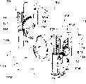
图5是移除壳罩的集尘器的透视图。Fig. 5 is a perspective view of the dust collector with the hood removed.
图6是一联动机构的结构透视图。Fig. 6 is a structural perspective view of a linkage mechanism.
图7是集尘器的横截面视图。Fig. 7 is a cross-sectional view of the dust collector.
图8是联动机构的一部分的透视图。Figure 8 is a perspective view of a portion of the linkage mechanism.
图9是在另一实施例中的集尘器主要部分的说明图。Fig. 9 is an explanatory diagram of a main part of a dust collector in another embodiment.
图10是传统的电动吸尘器结构的说明图。Fig. 10 is an explanatory diagram of the structure of a conventional electric vacuum cleaner.
具体实施方式Detailed ways
以下结合后面附图所示的具有依据本发明提出的集尘器的电动吸尘器的具体实施方式为例进行说明。The specific implementation of the electric vacuum cleaner with the dust collector according to the present invention shown in the accompanying drawings will be described below as an example.
请参阅图1所示,电动吸尘器10包括:一主体11;一集尘软管12,其一端连接到主体11,另一端连接到手边操作管13;一延伸管14,其可拆卸地连接到操作管13;以及一吸入单元15,其可拆卸地连接到延伸管14的前端。该集尘软管12的一端可拆卸地连接到设置于主体11内的连接口10A。Referring to Fig. 1, the
操作管13包括一操作部分13A,其设有复数个用于操作电动吸尘器10的操作开关13B。The
吸入单元15包括一吸入室(未图示),其设有一形成于吸入单元的底面的吸入口(未图示)并吸入灰尘。The
主体11包括一壳体20;一集尘器50,其可拆卸地设置在壳体20中设有的集尘器容纳室21中;一盖40,其具有一通过合页连接到壳体20的后部,以及一可上下开闭的前部,如图2所示。The
请参阅图4和图5所示,集尘器50包括一主体53,其具有设置在主体的前部(如图5中的左侧)的吸入口52,以及设置于主体后部的过滤器安装部分58。过滤器安装部分58具有一后部开口51。吸入口52通过连接口10A、集尘软管12和延伸管14与吸入单元15的吸入室连通。过滤器安装部分58形成为一圆柱形组件,其截面为矩形,并且,例如,一褶状过滤单元P可拆卸地设置在过滤器安装部分58内。Please refer to Fig. 4 and shown in Fig. 5,
集尘器容纳室21形成于壳体20的前部,集尘器容纳室21的上部开口22经常被盖40所关闭。电动鼓风机23设置于壳体20的后部,电动鼓风机23的吸入口24通过连接空气通道G与集尘器50的后部开口51连通。A dust
壳体20设有复数个排气孔25,并且后轮26上也设有复数个排气孔27。通过吸入口24被电动鼓风机23吸入并通过排出口(未图示)排出的空气从排气孔25和27释放出。The
主体53包括:一灰尘分离装置60,其将通过吸入口52吸入的含有灰尘的空气分离为空气和灰尘;一集尘室55,其设置于灰尘分离装置之下并且容纳灰尘分离装置60分离出的灰尘;一导向空气通道56,其用于将灰尘分离装置60分离出的灰尘导入集尘室55;以及一体式形成在集尘室55上的负压室57等等。集尘室55的底部上设有一用于排出灰尘的排出口53D,并且在该排出部设有一底盖59,使该排出口能够被打开和关闭。The
灰尘分离装置60具有一设有复数个开口61A的框架61,并且每个开口上设有一网状过滤器F1。一个喇叭状空气通道62形成于网状过滤器F1所包围的框架内侧。该空气通道62在前后方向上直线延伸。The
框架61具有:一前开口61a,其直接正对吸入口52且直径大于吸入口52的直径;和一后开口61b,其直径一般等于吸入口52的直径。The frame 61 has: a front opening 61a directly facing the
导向空气通道56连通框架62的后开口61b和设置在集尘室55的顶板55A的后部的引导口55d。The
负压室57与后部开口51连通,且灰尘分离装置60和导向空气通道56设置于负压室57内。灰尘分离装置60中的空气通道62通过框架61上每一个开口61A与负压室57连通。The negative pressure chamber 57 communicates with the
开口55Ha设置于集尘室的后壁55H上,集尘室55通过开口55Ha与负压室57连通,并且在开口55Ha上设置有过滤器F2。The opening 55Ha is provided on the rear wall 55H of the dust collection chamber, the
集尘器50上具有设置在主体53上部的提手部分54。如图4和图5所示,提手部分54包括一固定在主体53对侧的U字型带状组件。可以用手握住提手部分54来搬送主体53。The
还设有通过用手握住提手部分54来压缩集尘室55中所容纳的灰尘的压缩机构。There is also provided a compressing mechanism that compresses the dust contained in the
该压缩机构包括:一操纵杆85,其设置于在握住提手部分54时能够进行操作的位置上;以及一压缩组件100,其设置于集尘室55中使得当操作该操纵杆65时通过一联动机构70压缩集尘室55中的灰尘。该操纵杆85包括一个基本为U字型的带状组件,其在提手部分54上方并沿着该提手部分延伸,桥接设置于集尘器的主体53的对侧。The compression mechanism includes: an
如图6所示,压缩组件100设置在集尘室55的顶板55A之下,使得其可以上下移动,并且沿着导向空气通道56内侧设置的拱顶导向壁部101与压缩组件100一体式成型。As shown in FIG. 6 , the
而且,压缩组件100形成有正对灰尘分离装置60的后开口61b的开口102和正对集尘室55的引导口55d的开口103。对于压缩组件100的后缘部分,附有在过滤器F2上游的过滤器表面F2a滑动的叶片110。Furthermore, the
例如,联动机构70包括一连接操纵杆85的齿轮装置以及一与该齿轮装置连接的连杆装置。For example, the
该连杆装置具有可向上和向下延伸的连杆104和104,其可拆卸地附着于压缩组件100的对侧。如图7所示,连杆104和104插入设置在集尘室55的顶板55A的相对两端中的孔55f和55f,使得连杆能够上下移动。The linkage arrangement has upwardly and downwardly
齿轮装置包括设置在操纵杆85的腿86上的齿条72、与齿条72咬合的扇形齿轮73、设置在该齿轮73的轴74上的扇形齿轮75,以及如图8所示设置在连杆104和104上端用于与扇形齿轮75咬合的上下延伸的齿条组件105和105。The gear device comprises a
向下突出的轴87和87设置在操纵杆85的腿86和86的下部,轴87和87的上部形成有凸缘87F和87F。Downwardly protruding
如图5所示,轴87和87上附有弹簧S1和S1,弹簧S1和S1的上部咬合凸缘87F和87F,弹簧S1和S1的下部咬合集尘室55的顶板55A的上表面。操纵杆85受到弹簧S1和S1弹压力的弹压,并且设置于操纵杆85的相对的两端的凸出物85A和85A邻接于罩盒71和71的下表面,且操纵杆85受到限制以至于操纵杆85不能在超出预设量的范围移动。As shown in FIG. 5 , springs S1 and S1 are attached to the
每个扇形齿轮73可旋转地安装在每一个罩盒71上,每个扇形齿轮75的直径大于每个扇形齿轮73的直径。Each
当操纵杆85克服弹簧S1和S1的弹力作用而向下移动时,齿轮73和73逆时针转动(见图8),齿轮75和75同时与齿轮73和73一体进行逆时针转动。齿轮75和75的逆时针转动导致齿条106和106与连杆104和104一起向下移动。When the
因为每个齿轮75的直径大于每个齿轮73的直径,所以连杆104和104向下移动的量大于操纵杆85向下移动的量。Because the diameter of each
连杆104和104的下移导致压缩组件100也向下运动。The downward movement of the
这样,当操纵杆85向下移动时,压缩组件100通过联动机构70向下移动。Thus, when the
如图5所示,还设有一个用于打开和关闭底盖59的开关机构90,开关机构90包括一个设置在联动机构70附近的可上下移动的臂91,一个根据臂91的上下移动而绕着轴92旋转的连接组件93等等。As shown in Figure 5, a
如图4所示,臂91支撑在罩盒71内并可上下移动,并且臂91上部的操作部分91A通过罩盒71上设有的孔71B向上伸出。操作部分91A形成一个用于打开和关闭底盖59的操作部分。臂91被一个弹簧(未图示)向上弹压。As shown in FIG. 4 , the
如图5所示,连接组件93轴接于设置在侧壁55S上的轴92。如图5所示,钩94设置在连接组件93的下部,钩94咬合于设置在底盖59上的咬合部件(未图示)以使底盖59未被打开。As shown in FIG. 5 , the
当按压臂91的操作部分91A以便克服弹簧的弹力而向下移动臂91时,该连接组件93顺时针转动,并且连接组件93的钩94松开底盖59的咬合部以便打开底盖59。When the operating
如图4所示,沿箭头P1的方向绕左侧所示的轴线J1转动可以打开底盖59。这样,在按压臂91的操作部分91A时,通过开关机构90来打开底盖59。As shown in FIG. 4 , the
同时,该联动机构70以及开关机构90被保护它们的罩盒71所覆盖(见图4)。At the same time, the
电动吸尘器的主体11设有可以操作在集尘器的主体53上设置的提手部分54的操作装置。例如,该操作装置具有一设置在盖40里的孔41,和插入设置在孔41中的按钮42。该按钮42被一个弹簧(未图示)向上弹压,且通常用于盖住孔41。The
上下延伸的导向筒43设置在盖40的孔41之下,设置在按钮41的下表面的轴44可上下移动地插入导向筒43的导向孔43A中,以便按钮42可以上下移动。A guide cylinder 43 extending up and down is provided under the hole 41 of the
另外,凸缘45形成于按钮42的下表面,并且凸缘45邻接于此后描述的操纵杆85(见图2)。In addition, a
当按钮42向下移动时,该操纵杆85也向下移动。When the
[操作][operate]
接下来,说明如上所述结构的电动吸尘器的操作方法。Next, a method of operating the electric vacuum cleaner configured as described above will be described.
首先,如图2所示,电动吸尘器的主体11的集尘器容纳室21内设有集尘器50;如图1所示,集尘软管12连接到主体11的连接口10A,并且吸入单元15通过延伸管14连接操作管13。First, as shown in Figure 2, a
当操作操作管13上的操作部分13A的操作开关13B时,驱动电动鼓风机23。驱动电动鼓风机23使空气从电动鼓风机23的吸入口24处被吸入,通过连接空气通道G作用在集尘器50的后部开口51,因此,通过褶状过滤单元P,在集尘器50的负压室57内产生负压。When the operation switch 13B of the
负压通过集尘室55的过滤器F2、集尘室55的内部、以及灰尘分离装置60中的网过滤器F1,作用在灰尘分离装置60的空气通道62中,然后负压通过集尘器50的吸入口52,作用在集尘软管12、延伸管14和吸入单元15产生负压,使得通过吸入单元15吸入空气和灰尘。The negative pressure passes through the filter F2 of the
通过延伸管14和集尘软管12,吸入的空气和灰尘被引入到集尘器50的吸入口52。吸入吸入口52的灰尘和空气被吸入到灰尘分离装置60的空气通道62。Through the
吸入到空气通道62的一部分空气,通过灰尘分离装置60中的网状过滤器F1被吸入到集尘器50的负压室57中,进一步,通过集尘室50的后部开口51的褶状过滤单元P和连接空气通道G,进入到电动鼓风机23的吸入口24中。Part of the air sucked into the
另一方面,因为灰尘的质量远大于空气的质量,所以吸入灰尘分离装置60的空气通道62中的灰尘直接通过空气通道62,被压缩组件100的导向壁部101引导,并被引入到集尘室55中。也就是说,通过灰尘分离装置60来从空气中分离出灰尘,分离出的灰尘收集在集尘室55中。On the other hand, because the quality of the dust is much greater than that of the air, the dust sucked into the
此外,直接进入空气通道62中的空气通过压缩组件100的导向壁部101引导,并被引入集尘室55中。引入集尘室55中的空气通过集尘室55的后壁55H上的过滤器F2,被吸入到集尘器50的负压室57中,进一步通过集尘器50的后部开口51上的褶状过滤单元P和连接空气通道G,被吸入电动鼓风机23的吸入口24中。In addition, the air directly entering the
清洁工作结束时,按压设置在操作部分13A上的操作开关13B使电动鼓风机23停止。然后,按下设在主体11上的按钮42。当按钮42被按下时,操纵杆85克服弹簧S1和S1的弹力而被按下来。When the cleaning work is finished, the
当操纵杆85被按下时,压缩组件100被联动机构70向下移动。When the
当压缩组件100被向下按压时,压缩组件100的叶片110滑过过滤器F2的表面F2a,清除沾在过滤器表面F2a上的灰尘。另外,通过向下移动压缩组件100,存储在集尘室55中的灰尘被压缩。因此,能够在集尘室55中存储大量的灰尘。When the
当从按钮上松手时,操纵杆85通过弹簧S1和S1的弹力恢复到初始位置,压缩组件100和按钮42恢复到如图2所示的初始位置,与操纵杆85相连接。When the hand is released from the button, the
接下来,倾倒存储在集尘室55中的灰尘的例子如下所述:Next, an example of dumping the dust stored in the
首先,打开盖40,从主体11中取出集尘器50。当如图4所示的操作部分91A被压下时,通过开关机构90使底盖59沿箭头P1的方向绕轴线J1转动打开。First, the
然后,当同时握住操纵杆85和提手部分54时,操纵杆85被向下压向提手部分54,通过向下按压操纵杆85,通过联动机构70该压缩组件100被压到足够排出灰尘的位置。因此,集尘室55中的灰尘被从集尘器50的底口排出,从而容易倾倒灰尘。Then, when holding the
进而,因为压缩组件100能够从连杆104和104拆下,所以可以从压缩组件100上清除灰尘和类似物。Furthermore, since the
图9所示的是另一实施例中的集尘器150的一个部分。配置该集尘器150以通过联动机构70绕轴201转动压缩组件200到图中虚线所示位置。该过滤器F2为弧形,并且在转动压缩组件200时,叶片滑过过滤器F2的表面F2a且集尘室55中的灰尘通过压缩组件200排出。同时,在图9中,参考符号202,其表示的是一个开口。Figure 9 shows a portion of a dust collector 150 in another embodiment. The dust collector 150 is configured to rotate the compression assembly 200 around the shaft 201 to the position shown by the dotted line in the figure through the
产业上的可利用性Industrial availability
尽管上文描述了其中将根据本发明的集尘器用于电动吸尘器的实施例,但是所述集尘器的结构可应用于电动吸尘器之外的任何其它设备或装置。Although the embodiment in which the dust collector according to the present invention is used for an electric vacuum cleaner has been described above, the structure of the dust collector can be applied to any other equipment or devices other than electric vacuum cleaners.
Claims (6)
Applications Claiming Priority (2)
| Application Number | Priority Date | Filing Date | Title |
|---|---|---|---|
| JP2004113338 | 2004-04-07 | ||
| JP113338/2004 | 2004-04-07 |
Publications (2)
| Publication Number | Publication Date |
|---|---|
| CN1777385Atrue CN1777385A (en) | 2006-05-24 |
| CN100502753C CN100502753C (en) | 2009-06-24 |
Family
ID=35149716
Family Applications (3)
| Application Number | Title | Priority Date | Filing Date |
|---|---|---|---|
| CNB2004800426422AExpired - Fee RelatedCN100512740C (en) | 2004-04-07 | 2004-11-02 | Vacuum cleaner |
| CNB2004800087423AExpired - Fee RelatedCN100502753C (en) | 2004-04-07 | 2004-12-28 | Dust collectors and electric vacuum cleaners |
| CNU2005200001918UExpired - LifetimeCN2794414Y (en) | 2004-04-07 | 2005-01-18 | Electric vacuum cleaner |
Family Applications Before (1)
| Application Number | Title | Priority Date | Filing Date |
|---|---|---|---|
| CNB2004800426422AExpired - Fee RelatedCN100512740C (en) | 2004-04-07 | 2004-11-02 | Vacuum cleaner |
Family Applications After (1)
| Application Number | Title | Priority Date | Filing Date |
|---|---|---|---|
| CNU2005200001918UExpired - LifetimeCN2794414Y (en) | 2004-04-07 | 2005-01-18 | Electric vacuum cleaner |
Country Status (7)
| Country | Link |
|---|---|
| EP (1) | EP1733669B1 (en) |
| JP (1) | JPWO2005099545A1 (en) |
| KR (1) | KR100788777B1 (en) |
| CN (3) | CN100512740C (en) |
| DE (1) | DE602004029614D1 (en) |
| RU (1) | RU2327412C2 (en) |
| WO (1) | WO2005099545A1 (en) |
Cited By (17)
| Publication number | Priority date | Publication date | Assignee | Title |
|---|---|---|---|---|
| US7749295B2 (en) | 2005-12-10 | 2010-07-06 | Lg Electronics Inc. | Vacuum cleaner with removable dust collector, and methods of operating the same |
| US7770253B2 (en) | 2005-12-10 | 2010-08-10 | Lg Electronics Inc. | Vacuum cleaner with removable dust collector, and methods of operating the same |
| US7785396B2 (en) | 2005-12-10 | 2010-08-31 | Lg Electronics Inc. | Vacuum cleaner with removable dust collector, and methods of operating the same |
| US7882592B2 (en) | 2005-12-10 | 2011-02-08 | Lg Electronics Inc. | Vacuum cleaner |
| CN101229032B (en)* | 2007-01-24 | 2011-04-06 | Lg电子株式会社 | Dust collector of vacuum cleaner |
| US7958598B2 (en) | 2007-01-24 | 2011-06-14 | Lg Electronics Inc. | Vacuum cleaner |
| US7987551B2 (en) | 2005-12-10 | 2011-08-02 | Lg Electronics Inc. | Vacuum cleaner |
| US7992252B2 (en) | 2009-02-12 | 2011-08-09 | Lg Electronics Inc. | Vacuum cleaner |
| US8012250B2 (en) | 2005-12-10 | 2011-09-06 | Lg Electronics Inc. | Vacuum cleaner |
| US8151409B2 (en) | 2009-02-26 | 2012-04-10 | Lg Electronics Inc. | Vacuum cleaner |
| US8163051B2 (en) | 2007-01-24 | 2012-04-24 | Lg Electronics Inc. | Dust collector of vacuum cleaner |
| US8281455B2 (en) | 2005-12-10 | 2012-10-09 | Lg Electronics Inc. | Vacuum cleaner |
| US8404034B2 (en) | 2005-12-10 | 2013-03-26 | Lg Electronics Inc. | Vacuum cleaner and method of controlling the same |
| US8544143B2 (en) | 2005-12-10 | 2013-10-01 | Lg Electronics Inc. | Vacuum cleaner with removable dust collector, and methods of operating the same |
| US8713752B2 (en) | 2009-03-13 | 2014-05-06 | Lg Electronics Inc. | Vacuum cleaner |
| US8978197B2 (en) | 2009-03-13 | 2015-03-17 | Lg Electronics Inc. | Vacuum cleaner |
| CN105411482A (en)* | 2015-12-10 | 2016-03-23 | 江苏美的清洁电器股份有限公司 | Vertical dust collector |
Families Citing this family (17)
| Publication number | Priority date | Publication date | Assignee | Title |
|---|---|---|---|---|
| ATE449646T1 (en)* | 2006-02-24 | 2009-12-15 | Lg Electronics Inc | DUST COLLECTION CONTAINER AND VACUUM CLEANER |
| EP1825797B1 (en)* | 2006-02-24 | 2013-10-23 | LG Electronic Inc. | Method of controlling vacuum cleaner |
| RU2375951C2 (en)* | 2007-01-24 | 2009-12-20 | ЭлДжи ЭЛЕКТРОНИКС ИНК. | Vacuum cleaner (versions) |
| PL206801B1 (en)* | 2007-04-11 | 2010-09-30 | Zelmer Spo & Lstrok Ka Akcyjna | Blocking device for electric hoover |
| US20080264015A1 (en) | 2007-04-30 | 2008-10-30 | Samsung Gwangju Electronics Co., Ltd | Dust compressing apparatus of vacuum cleaner |
| US7785381B2 (en)* | 2007-04-30 | 2010-08-31 | Samsung Gwangju Electronics Co., Ltd. | Dust collecting apparatus with combined compacting and filter cleaning for a vacuum cleaner |
| KR100912318B1 (en)* | 2007-07-16 | 2009-08-14 | 엘지전자 주식회사 | Vacuum cleaner and his dust collector |
| KR100842963B1 (en)* | 2007-07-16 | 2008-07-01 | 엘지전자 주식회사 | Vacuum cleaner |
| RU2428916C2 (en)* | 2007-07-16 | 2011-09-20 | ЭлДжи ЭЛЕКТРОНИКС ИНК. | Vacuum cleaner |
| JP5306968B2 (en)* | 2009-11-06 | 2013-10-02 | 三菱電機株式会社 | Electric vacuum cleaner |
| JP2013128670A (en)* | 2011-12-21 | 2013-07-04 | Toshiba Corp | Vacuum cleaner |
| WO2013171618A1 (en)* | 2012-05-14 | 2013-11-21 | Koninklijke Philips N.V. | Robotic vacuum cleaner with removable dust container |
| JP2014018300A (en)* | 2012-07-13 | 2014-02-03 | Toshiba Corp | Vacuum cleaner |
| KR101476209B1 (en)* | 2013-01-08 | 2014-12-24 | 엘지전자 주식회사 | Cleaner for Bedding |
| KR101858067B1 (en)* | 2016-05-03 | 2018-05-18 | 엘지전자 주식회사 | Vacuum cleaner |
| EP3323334B1 (en) | 2016-11-17 | 2019-06-05 | Black & Decker Inc. | Vacuum cleaner |
| JP7222691B2 (en)* | 2018-12-18 | 2023-02-15 | 東芝ライフスタイル株式会社 | vacuum cleaner |
Family Cites Families (7)
| Publication number | Priority date | Publication date | Assignee | Title |
|---|---|---|---|---|
| JPS5648356U (en)* | 1979-09-20 | 1981-04-30 | ||
| JPS6058646B2 (en)* | 1981-02-17 | 1985-12-20 | 東芝テック株式会社 | vacuum cleaner |
| JPS57173650U (en)* | 1981-04-30 | 1982-11-01 | ||
| SU1326236A1 (en)* | 1986-02-03 | 1987-07-30 | Ю. Ф. Киселев, В. М. Опанасюк и А. В. Кр чек | Vacuum cleaner |
| DE60121652T2 (en)* | 2000-03-24 | 2007-07-26 | Sharp K.K. | Electric vacuum cleaner |
| JP2003190059A (en)* | 2001-12-27 | 2003-07-08 | Matsushita Electric Ind Co Ltd | Electric vacuum cleaner |
| JP3699679B2 (en)* | 2001-12-28 | 2005-09-28 | 松下電器産業株式会社 | Vacuum cleaner |
- 2004
- 2004-11-02CNCNB2004800426422Apatent/CN100512740C/ennot_activeExpired - Fee Related
- 2004-12-28RURU2006115703/11Apatent/RU2327412C2/ennot_activeIP Right Cessation
- 2004-12-28KRKR1020057018957Apatent/KR100788777B1/ennot_activeExpired - Fee Related
- 2004-12-28DEDE602004029614Tpatent/DE602004029614D1/ennot_activeExpired - Lifetime
- 2004-12-28JPJP2006519316Apatent/JPWO2005099545A1/enactivePending
- 2004-12-28CNCNB2004800087423Apatent/CN100502753C/ennot_activeExpired - Fee Related
- 2004-12-28WOPCT/JP2004/019621patent/WO2005099545A1/ennot_activeApplication Discontinuation
- 2004-12-28EPEP04807976Apatent/EP1733669B1/ennot_activeExpired - Lifetime
- 2005
- 2005-01-18CNCNU2005200001918Upatent/CN2794414Y/ennot_activeExpired - Lifetime
Cited By (29)
| Publication number | Priority date | Publication date | Assignee | Title |
|---|---|---|---|---|
| US8312593B2 (en) | 2005-12-10 | 2012-11-20 | Lg Electronics Inc. | Vacuum cleaner with removable dust collector, and methods of operating the same |
| US7998234B2 (en) | 2005-12-10 | 2011-08-16 | Lg Electronics Inc. | Vacuum cleaner with removable dust collector, and methods of operating the same |
| US7785396B2 (en) | 2005-12-10 | 2010-08-31 | Lg Electronics Inc. | Vacuum cleaner with removable dust collector, and methods of operating the same |
| US7882592B2 (en) | 2005-12-10 | 2011-02-08 | Lg Electronics Inc. | Vacuum cleaner |
| US8544143B2 (en) | 2005-12-10 | 2013-10-01 | Lg Electronics Inc. | Vacuum cleaner with removable dust collector, and methods of operating the same |
| US8404034B2 (en) | 2005-12-10 | 2013-03-26 | Lg Electronics Inc. | Vacuum cleaner and method of controlling the same |
| US7770253B2 (en) | 2005-12-10 | 2010-08-10 | Lg Electronics Inc. | Vacuum cleaner with removable dust collector, and methods of operating the same |
| US7987551B2 (en) | 2005-12-10 | 2011-08-02 | Lg Electronics Inc. | Vacuum cleaner |
| US8240001B2 (en) | 2005-12-10 | 2012-08-14 | Lg Electronics Inc. | Vacuum cleaner with removable dust collector, and methods of operating the same |
| US7749295B2 (en) | 2005-12-10 | 2010-07-06 | Lg Electronics Inc. | Vacuum cleaner with removable dust collector, and methods of operating the same |
| US8012250B2 (en) | 2005-12-10 | 2011-09-06 | Lg Electronics Inc. | Vacuum cleaner |
| US8021452B2 (en) | 2005-12-10 | 2011-09-20 | Lg Electronics Inc. | Vacuum cleaner with removable dust collector, and methods of operating the same |
| US8043397B2 (en) | 2005-12-10 | 2011-10-25 | Lg Electronics Inc. | Vacuum cleaner with removable dust collector, and methods of operating the same |
| US8043410B2 (en) | 2005-12-10 | 2011-10-25 | Lg Electronics Inc. | Vacuum cleaner with removable dust collector, and methods of operating the same |
| US8060979B2 (en) | 2005-12-10 | 2011-11-22 | Lg Electronics Inc. | Vacuum cleaner with removable dust collector, and methods of operating the same |
| US8281455B2 (en) | 2005-12-10 | 2012-10-09 | Lg Electronics Inc. | Vacuum cleaner |
| US7992253B2 (en) | 2007-01-24 | 2011-08-09 | Lg Electronics Inc. | Vacuum cleaner |
| US8163051B2 (en) | 2007-01-24 | 2012-04-24 | Lg Electronics Inc. | Dust collector of vacuum cleaner |
| US7958598B2 (en) | 2007-01-24 | 2011-06-14 | Lg Electronics Inc. | Vacuum cleaner |
| CN101229032B (en)* | 2007-01-24 | 2011-04-06 | Lg电子株式会社 | Dust collector of vacuum cleaner |
| US8726459B2 (en) | 2007-01-24 | 2014-05-20 | Lg Electronics Inc. | Vacuum cleaner |
| US7992252B2 (en) | 2009-02-12 | 2011-08-09 | Lg Electronics Inc. | Vacuum cleaner |
| US8528163B2 (en) | 2009-02-12 | 2013-09-10 | Lg Electronics Inc. | Vacuum cleaner |
| US8881343B2 (en) | 2009-02-12 | 2014-11-11 | Lg Electronics Inc. | Vacuum cleaner |
| US8151409B2 (en) | 2009-02-26 | 2012-04-10 | Lg Electronics Inc. | Vacuum cleaner |
| US8713752B2 (en) | 2009-03-13 | 2014-05-06 | Lg Electronics Inc. | Vacuum cleaner |
| US8978197B2 (en) | 2009-03-13 | 2015-03-17 | Lg Electronics Inc. | Vacuum cleaner |
| CN105411482A (en)* | 2015-12-10 | 2016-03-23 | 江苏美的清洁电器股份有限公司 | Vertical dust collector |
| CN105411482B (en)* | 2015-12-10 | 2018-07-13 | 江苏美的清洁电器股份有限公司 | Vertical type dust collector |
Also Published As
| Publication number | Publication date |
|---|---|
| CN100502753C (en) | 2009-06-24 |
| EP1733669B1 (en) | 2010-10-13 |
| KR20060058052A (en) | 2006-05-29 |
| RU2327412C2 (en) | 2008-06-27 |
| KR100788777B1 (en) | 2007-12-27 |
| RU2006115703A (en) | 2007-11-20 |
| CN100512740C (en) | 2009-07-15 |
| JPWO2005099545A1 (en) | 2008-03-06 |
| WO2005099545A1 (en) | 2005-10-27 |
| EP1733669A4 (en) | 2007-11-21 |
| CN2794414Y (en) | 2006-07-12 |
| EP1733669A1 (en) | 2006-12-20 |
| CN1925777A (en) | 2007-03-07 |
| DE602004029614D1 (en) | 2010-11-25 |
Similar Documents
| Publication | Publication Date | Title |
|---|---|---|
| CN1777385A (en) | Dust collectors and electric vacuum cleaners | |
| CN2917530Y (en) | Dust collecting container and electric vacuum cleaner equipped with such dust collecting container | |
| CN1152646C (en) | Cyclone dust collection device for vacuum cleaners | |
| JP4873355B2 (en) | Handheld cleaning tool | |
| CN1429521A (en) | Vacuum cleaners and electric vacuum cleaners | |
| KR101356519B1 (en) | Vacuum cleaner | |
| CN101044963A (en) | Vacuum cleaner | |
| TWI342198B (en) | ||
| EP1987755A3 (en) | Vacuum cleaner | |
| CN1434688A (en) | Multi cyclone vacuum cleaner | |
| CN101044962A (en) | Electric vacuum cleaner | |
| KR20060117001A (en) | Dust collection unit for vacuum cleaner | |
| CN101032382A (en) | Vacuum cleaner | |
| JP2009504311A (en) | Vacuum cleaner | |
| JP2011188952A (en) | Dust collecting device and vacuum cleaner | |
| CN1119118C (en) | Electric dust cleaner | |
| US20070039124A1 (en) | Exhaust structure of vacuum cleaner | |
| CN104490341A (en) | Electric dust collector | |
| CN1803081A (en) | Electric dust collector | |
| KR101282536B1 (en) | Dust collecting apparatus and electric cleaner | |
| WO2014030552A1 (en) | Electric vacuum cleaner | |
| CN112438648A (en) | Vacuum cleaner with a vacuum cleaner head | |
| CN101077285A (en) | Electric vacuum cleaner | |
| WO2005099544A1 (en) | Vacuum cleaner | |
| CN2860330Y (en) | Vacuum cleaner head and electric vacuum cleaner using the head |
Legal Events
| Date | Code | Title | Description |
|---|---|---|---|
| C06 | Publication | ||
| PB01 | Publication | ||
| C10 | Entry into substantive examination | ||
| SE01 | Entry into force of request for substantive examination | ||
| C14 | Grant of patent or utility model | ||
| GR01 | Patent grant | ||
| C41 | Transfer of patent application or patent right or utility model | ||
| TR01 | Transfer of patent right | Effective date of registration:20160817 Address after:Tokyo, Japan Patentee after:TOSHIBA LIFESTYLE PRODUCTS & SERVICES Corp. Address before:Tokyo, Japan Patentee before:TOSHIBA TEC Kabushiki Kaisha | |
| CF01 | Termination of patent right due to non-payment of annual fee | Granted publication date:20090624 | |
| CF01 | Termination of patent right due to non-payment of annual fee |