CN1772525B - Separate series-parallel hybrid dual power drive system - Google Patents
Separate series-parallel hybrid dual power drive systemDownload PDFInfo
- Publication number
- CN1772525B CN1772525BCN2004100903809ACN200410090380ACN1772525BCN 1772525 BCN1772525 BCN 1772525BCN 2004100903809 ACN2004100903809 ACN 2004100903809ACN 200410090380 ACN200410090380 ACN 200410090380ACN 1772525 BCN1772525 BCN 1772525B
- Authority
- CN
- China
- Prior art keywords
- drive
- drive system
- unit
- clutch
- motor unit
- Prior art date
- Legal status (The legal status is an assumption and is not a legal conclusion. Google has not performed a legal analysis and makes no representation as to the accuracy of the status listed.)
- Expired - Lifetime
Links
Images


Classifications
- B—PERFORMING OPERATIONS; TRANSPORTING
- B60—VEHICLES IN GENERAL
- B60K—ARRANGEMENT OR MOUNTING OF PROPULSION UNITS OR OF TRANSMISSIONS IN VEHICLES; ARRANGEMENT OR MOUNTING OF PLURAL DIVERSE PRIME-MOVERS IN VEHICLES; AUXILIARY DRIVES FOR VEHICLES; INSTRUMENTATION OR DASHBOARDS FOR VEHICLES; ARRANGEMENTS IN CONNECTION WITH COOLING, AIR INTAKE, GAS EXHAUST OR FUEL SUPPLY OF PROPULSION UNITS IN VEHICLES
- B60K6/00—Arrangement or mounting of plural diverse prime-movers for mutual or common propulsion, e.g. hybrid propulsion systems comprising electric motors and internal combustion engines
- B60K6/20—Arrangement or mounting of plural diverse prime-movers for mutual or common propulsion, e.g. hybrid propulsion systems comprising electric motors and internal combustion engines the prime-movers consisting of electric motors and internal combustion engines, e.g. HEVs
- B60K6/42—Arrangement or mounting of plural diverse prime-movers for mutual or common propulsion, e.g. hybrid propulsion systems comprising electric motors and internal combustion engines the prime-movers consisting of electric motors and internal combustion engines, e.g. HEVs characterised by the architecture of the hybrid electric vehicle
- B60K6/44—Series-parallel type
- B60K6/442—Series-parallel switching type
- Y—GENERAL TAGGING OF NEW TECHNOLOGICAL DEVELOPMENTS; GENERAL TAGGING OF CROSS-SECTIONAL TECHNOLOGIES SPANNING OVER SEVERAL SECTIONS OF THE IPC; TECHNICAL SUBJECTS COVERED BY FORMER USPC CROSS-REFERENCE ART COLLECTIONS [XRACs] AND DIGESTS
- Y02—TECHNOLOGIES OR APPLICATIONS FOR MITIGATION OR ADAPTATION AGAINST CLIMATE CHANGE
- Y02T—CLIMATE CHANGE MITIGATION TECHNOLOGIES RELATED TO TRANSPORTATION
- Y02T10/00—Road transport of goods or passengers
- Y02T10/60—Other road transportation technologies with climate change mitigation effect
- Y02T10/62—Hybrid vehicles
Landscapes
- Engineering & Computer Science (AREA)
- Chemical & Material Sciences (AREA)
- Combustion & Propulsion (AREA)
- Transportation (AREA)
- Mechanical Engineering (AREA)
- Electric Propulsion And Braking For Vehicles (AREA)
- Hybrid Electric Vehicles (AREA)
Abstract
Translated fromChinese
Description
Translated fromChinese技术领域technical field
本发明涉及一种动力驱动系统,尤指一种分离式串并联混合式双动力驱动系统。The invention relates to a power drive system, in particular to a separate series-parallel hybrid double power drive system.
背景技术Background technique
传统陆上、或水上、或空域载具通常为单动力系统,近年因节约能源及节制污染的需求,而致力于双动力驱动系统的研发,其中具有内燃引擎输出回转动能与电力驱动马达输出回转动能的双动力混合动力系统颇有进展,回顾已发展的双动力混合动力系统包括:Traditional land, water, or airspace vehicles are usually single-power systems. In recent years, due to the needs of energy saving and pollution control, they have devoted themselves to the research and development of dual-power drive systems, which have internal combustion engine output rotary kinetic energy and electric drive motor output. The dual-power hybrid system with rotary kinetic energy has made considerable progress. Reviewing the developed dual-power hybrid system includes:
1、串联式混合动力系统:为以引擎驱动发电机,再以发电机电能驱动马达产生回转动能进而驱动负载,此系统的缺点为在不同负载率时系统效率差异太大,且由马达及发电机负担全部功率,所需电机额定容量大,占用空间大、重量增加、成本高;1. Series hybrid power system: the engine drives the generator, and then the generator uses the electric energy of the generator to drive the motor to generate rotary kinetic energy and then drive the load. The generator bears all the power, and the required motor has a large rated capacity, takes up a lot of space, increases in weight, and costs high;
2、储能式串联驱动系统:于正常负载时,为以引擎驱动发电机,再以发电机电能驱动马达输出回转动能进而驱动负载,于轻载时,发电机的电能除驱动马达外,部份输入储放电装置以储存电能,供在引擎停止时,由储放电装置的电能驱动马达输出回转动能进而驱动负载,以减少污染提升能源效率,而于重载时,由引擎所驱动发电机的电能及储放电装置的电能,共同输往马达以输出回转动能驱动负载;2. Energy storage type series drive system: under normal load, the engine is used to drive the generator, and then the electric energy of the generator is used to drive the motor to output rotary kinetic energy to drive the load. Part of the input storage and discharge device is used to store electric energy. When the engine is stopped, the electric energy of the storage and discharge device drives the motor to output rotary kinetic energy and then drives the load to reduce pollution and improve energy efficiency. When the engine is heavy, it is driven by the engine to generate electricity. The electrical energy of the motor and the electrical energy of the storage and discharge device are jointly output to the motor to output rotary kinetic energy to drive the load;
3、并联式混合动力系统:于正常负载时,由引擎输出的回转动能直接驱动负载,而在轻载时,引擎所牵动的马达被切换为作发电机功能运转,以对储放电装置充电或对其他负载供电,或于引擎停止运转时,由储放电装置的电能驱动马达以输出回转动能驱动负载,以提升能源效率减少污染,重载时则由引擎输出的回转动能,及储放电装置电能驱动马达的回转动能共同驱动负载,此系统的缺点为需设置足够容量的储放电装置。3. Parallel hybrid power system: under normal load, the rotary kinetic energy output by the engine directly drives the load, while under light load, the motor driven by the engine is switched to function as a generator to charge the storage and discharge device Or supply power to other loads, or when the engine is stopped, the electric energy of the storage and discharge device drives the motor to output rotary kinetic energy to drive the load, so as to improve energy efficiency and reduce pollution. The electrical energy of the discharge device drives the rotary kinetic energy of the motor to jointly drive the load. The disadvantage of this system is that a storage and discharge device with sufficient capacity needs to be installed.
发明内容Contents of the invention
本发明要解决的技术问题是提供一种分离式串并联混合式双动力驱动系统,为用以供驱动陆上或水上、水下或空域的载具产业机具或其他以回转动能驱动的负载;The technical problem to be solved by the present invention is to provide a separate series-parallel hybrid dual-power drive system, which is used to drive vehicles, industrial equipment or other loads driven by rotary kinetic energy on land or on water, underwater or airspace ;
此项分离式串并联混合式双动力驱动系统,为设有两个或两个以上的分离式驱动系统,可供作独立运作各别驱动负载,或经由各别驱动的负载结合于共同机体;This separate series-parallel hybrid dual-power drive system is equipped with two or more separate drive systems, which can be used to drive loads independently, or combine the loads driven separately into a common body;
此项系统中分离式驱动系统中,设有第一驱动系统及第二驱动系统,第一驱动系统设有主动动力源、以及主要作为发电机的第一电机单元、以及选择性设置主要作为电动机功能的第二电机单元、以及操控回转动能传输状态的离合器组;第二驱动系统为设有主要作为电动机功能的第二电机单元作为第二驱动系统的回转动力源;In the separated drive system of this system, a first drive system and a second drive system are provided, and the first drive system is provided with an active power source, a first motor unit mainly used as a generator, and an optional setting mainly used as a motor Functional second motor unit, and a clutch set that controls the transmission state of rotary kinetic energy; the second drive system is provided with the second motor unit that mainly functions as a motor as the rotary power source of the second drive system;
此外并可选择性设置离合器,以操控各独立驱动系统间回转动能的相互传输或切断;In addition, the clutch can be selectively set to control the mutual transmission or cut-off of the rotary kinetic energy between the independent drive systems;
前述分离式串并联混合式双动力驱动系统,可藉人工或控制系统的操控,使主动回转动力源与第一电机单元间的传动关系呈耦合联结的状态,而第一电机单元与第二电机单元间的传动关系呈分离状态,而由主动回转动力源驱动第一电机单元发电输出电能,以驱动第二电机单元作电动机功能运转,而作串联式混合动力系统相关功能的运作;或由主动回转动力源的回转动能经离合器的操控,以输出回转动能驱动第一驱动系统的负载、或驱动第二驱动系统的负载或同时驱动两者的负载;The aforementioned separate series-parallel hybrid dual-power drive system can be manipulated manually or by the control system to make the transmission relationship between the active rotary power source and the first motor unit be in a coupled state, while the first motor unit and the second motor unit The transmission relationship between the units is separated, and the first motor unit is driven by the active rotary power source to generate and output electric energy to drive the second motor unit to operate as a motor, and to operate related functions of the series hybrid system; or by the active rotary power source The rotary kinetic energy of the rotary power source is manipulated by the clutch to output the rotary kinetic energy to drive the load of the first drive system, or drive the load of the second drive system, or drive both loads at the same time;
或由主动回转动力源与上述第一电机单元及第二电机单元及选择性设置的储放电装置结合,以作并联式混合动力系统相关功能的运作,而提供较多运转功能的一种创新的双动力驱动系统。Or an innovative one that provides more running functions by combining the active rotary power source with the above-mentioned first motor unit and second motor unit and the selectively provided storage and discharge device for the operation of related functions of the parallel hybrid power system. Dual power drive system.
本发明为由设有主动回转动力源包括以内燃引擎作为回转动力源、及主要作为发电机功能的第一电机组、及选择性设置第二电机组、及离合器所构成的第一驱动系统,与设有主要作为电动机功能的第二电机组的第二驱动系统,及设有供操控第一驱动系统与第二驱动系统之间回转动能传输状态的可操控离合器,而构成具有可作分离式的串联式混合动力系统运作、或并联式混合动力系统功能运作的分离式串并联混合式双动力驱动系统,系统的运作包括将系统操控为作串联式混合动力系统的运作状态,此时以引擎的回转动能,驱动设置于第一驱动系统的第一电机单元作发电机运转,而第一电机单元与第二电机单元间的离合器呈不作传动的脱离状态,第一电机单元发电输出的电能供驱动设置于第一驱动系统、或设置于第二驱动系统的第二电机单元作为电动机功能运转,以输出回转动能驱动负载,而作串联式混合动力系统的运作状态;The present invention is a first drive system composed of an active rotary power source including an internal combustion engine as a rotary power source, a first motor unit mainly functioning as a generator, a second motor unit, and a clutch, It is equipped with the second drive system of the second motor unit mainly functioning as a motor, and is provided with a controllable clutch for controlling the rotary kinetic energy transmission state between the first drive system and the second drive system, thus forming a separable The series-type hybrid system operates, or the separated series-parallel hybrid dual-power drive system operates with the function of the parallel hybrid system. The operation of the system includes controlling the system to operate as a series hybrid system. At this time, The rotary kinetic energy of the engine drives the first motor unit arranged in the first drive system to operate as a generator, and the clutch between the first motor unit and the second motor unit is in a disengaged state without transmission, and the first motor unit generates output Electric energy is used to drive the second motor unit installed in the first drive system or in the second drive system to function as a motor, and to output rotary kinetic energy to drive the load, so as to be in the operating state of the series hybrid power system;
于常态负载时,由引擎输出的回转动能,经传动装置单独驱动第一驱动系统、或经离合器的操控单独驱动第二驱动系统、或经离合器的操控同时驱动第一及第二驱动系统的负载。Under normal load, the rotary kinetic energy output by the engine drives the first drive system alone through the transmission device, or drives the second drive system independently through the control of the clutch, or simultaneously drives the first and second drive systems through the control of the clutch. load.
此项分离式串并联混合式双动力驱动系统,可依需要进一步选择设置或不设置储放电装置,若系统选择设置储放电装置,其主要运转功能含:This separate series-parallel hybrid dual-power drive system can further choose to install or not install a storage and discharge device according to needs. If the system chooses to install a storage and discharge device, its main operating functions include:
由储放电装置的电能,驱动设置于第一驱动系统的第一电机单元作电动机功能运转,或驱动设置于第一驱动系统或第二驱动系统的第二电机单元,作电动机功能运转以输出回转功能供驱动负载。The electric energy of the storage and discharge device is used to drive the first motor unit installed in the first drive system to operate as a motor, or to drive the second motor unit installed in the first drive system or the second drive system to operate as a motor to output rotation function for driving loads.
在轻负载时,除由引擎输出的回转动能直接驱动负载外,并可由设置于第一驱动系统的第一电机单元,及设置于第一驱动系统或第二驱动系统的第二电机单元的全部,或其中部分电机单元,作为发电机功能运转,其发电的电能供对储放电装置充电或对其他使用电能的负载供电。When the load is light, in addition to the rotary kinetic energy output by the engine to directly drive the load, it can also be provided by the first motor unit of the first drive system and the second motor unit of the first drive system or the second drive system. All, or some of the motor units, operate as a generator, and the electric energy generated by it is used to charge the storage and discharge device or to supply power to other loads that use electric energy.
于常态负载时,由引擎输出的回转动能经传动装置单独驱动第一驱动系统、或单独驱动第二驱动系统、或同时驱动第一及第二驱动系统的负载。During normal load, the rotary kinetic energy output by the engine drives the first drive system alone, or the second drive system alone, or simultaneously drives the loads of the first drive system and the second drive system through the transmission device.
于重负载时,可由储放电装置的电能,驱动设置于第一驱动系统的第一电机单元,及设置于第一或第二驱动系统的第二电机单元的全部、或其中部分电机单元作电动机功能运转,并与引擎动力共同驱动负载,作为并联式混合动力系统的运作。When the load is heavy, the electric energy of the storage and discharge device can be used to drive all or part of the first motor unit installed in the first drive system and the second motor unit installed in the first or second drive system as a motor Functional operation, and drive the load together with the engine power, as a parallel hybrid system operation.
本发明的基本系统包括由用于产生回转动能的主动回转动力源包括以内燃引擎作为回转动力源,直接、或经依需要选择性设置的可操控离合器,及具有多段或无段变速功能、或倒档功能、或空档功能或扭力转换功能的变速单元以驱动负载,并由主动回转动力源的回转动能,供驱动第一电机单元作发电机功能运转以共同构成第一驱动系统;The basic system of the present invention includes an active rotary power source for generating rotary kinetic energy, including an internal combustion engine as a rotary power source, a controllable clutch directly or selectively set according to needs, and has a multi-stage or stepless speed change function, The transmission unit with reverse gear function, neutral gear function or torque conversion function is used to drive the load, and the rotary kinetic energy of the active rotary power source is used to drive the first motor unit to operate as a generator to jointly constitute the first drive system;
第一电机单元所发电的电能,供驱动设置于第一驱动系统或设置于第二驱动系统的第二电机单元,作电动机功能运转以供驱动负载,或对其他使用电能的负载供电;The electric energy generated by the first motor unit is used to drive the second motor unit installed in the first drive system or in the second drive system to operate as a motor to drive loads, or to supply power to other loads that use electric energy;
设置于第一驱动系统的第二电机单元为用以协助驱动第一驱动系统所属的负载,可依系统需要选择设置或不设置。The second motor unit arranged in the first drive system is used to assist in driving the load belonging to the first drive system, and can be selected or not provided according to system requirements.
第二驱动系统以第二电机单元作为动力源,可直接或经依需要选择性设置的变速单元,以驱动所属的负载进而构成第二驱动系统,第二驱动系统与主动回转动力源之间,可依需要选择性设置传动单元、离合器等传动装置,以操控两者之间作回转动能的联结传输或不作联结的分离运作;或于第二驱动系统的第二电机单元转部或所驱动的回转机构,与第一驱动系统的第一电机单元或第二电机单元的转部或所驱动的回转机构之间,依需要选择性设置传动单元、离合器等传动装置,以操控两者之间作回转功能的联结传输或作分离的运作。The second drive system uses the second motor unit as the power source, which can drive the associated loads directly or via the speed change unit selectively set according to the needs to form the second drive system. Between the second drive system and the active rotary power source, Transmission units such as transmission units and clutches can be selectively set as required to control the connection and transmission of rotary kinetic energy between the two or the separation operation without connection; or in the second motor unit rotation part of the second drive system or driven Between the slewing mechanism and the rotating part of the first motor unit or the second motor unit of the first drive system or the driven slewing mechanism, transmission units, clutches and other transmission devices are selectively arranged as required to control the rotation between the two Functional connection transmission or separate operation.
此项分离式串并联混合式双动力驱动系统的运作,包括于轻载时,系统可被操控作串联式混合动力系统相关功能的运作、或被操控作并联式混合动力系统相关功能的运作;于系统作并联式混合动力系统运作时,其主动回转动力源可为呈与第一驱动系统所属的负载作传动联结的驱动状态,或呈不与第一驱动系统所属负载作传动联结的脱离状态;The operation of this separated series-parallel hybrid dual-power drive system includes that under light load, the system can be controlled to operate related functions of a series hybrid power system, or be controlled to operate related functions of a parallel hybrid power system; When the system operates as a parallel hybrid system, its active rotary power source can be in a drive state that is in transmission connection with the load belonging to the first drive system, or in a disengaged state that is not in transmission connection with the load in the first drive system ;
于系统作串联式混合动力系统运作时,其主动回转动力源可依运转需要与第一驱动系统所属负载呈传动联结,或呈不作传动联结的脱离状态,而第一驱动系统与第二驱动系统间的离合器则呈脱开状态,由作为主动回转动力源的引擎接受人工或控制系统的操控以输出回转功能,供驱动第一电机单元作发电机功能运转,以其发电的电能驱动设置于第一或第二驱动系统的第二电机单元,作电动机功能运转以驱动负载;When the system operates as a series hybrid power system, its active rotary power source can be connected to the load of the first drive system according to the operation needs, or it can be disengaged without transmission connection, and the first drive system and the second drive system The clutch between them is disengaged, and the engine as the active rotary power source is controlled manually or by the control system to output the rotary function, which is used to drive the first motor unit to operate as a generator, and the electric energy generated by it drives the second motor unit. The second motor unit of the first or second drive system operates as a motor to drive a load;
常态负载或重载时,系统可被操控为呈并联式混合动力系统相关功能的运作,包括由引擎的回转动能驱动第一驱动系统、或驱动第二驱动系统或两者同时驱动;若系统依需要选择加设储放电装置,则可由设置于第一驱动系统的第一电机单元、或设置于第一或第二驱动系统的第二电机单元或两者其中之一,藉储放电装置的电能作电动机功能运转,于重载或起动或加速时与引擎动能共同驱动负载,或于轻载时或市区行驶时,可作电动机功能运转驱动负载;Under normal load or heavy load, the system can be controlled to operate as a parallel hybrid system, including driving the first drive system by the rotary kinetic energy of the engine, or driving the second drive system or both simultaneously; if the system If you choose to add a storage and discharge device as needed, you can use the power of the storage and discharge device by the first motor unit installed in the first drive system, or the second motor unit installed in the first or second drive system, or one of the two. The electric energy can be used as a motor to drive the load together with the kinetic energy of the engine during heavy loads or when starting or accelerating, or it can be used as a motor to drive the load when it is lightly loaded or driving in urban areas;
此项分离式串并联混合式双动力驱动系统,若选择以引擎作为主动回转动力源,则其主要运作功能含:This separate series-parallel hybrid dual-power drive system, if the engine is selected as the active rotary power source, its main operating functions include:
——由引擎动力的回转动能经传动单元驱动设置于第一驱动系统的负载,或驱动设置于第二驱动系统的负载或两者同时驱动;——The rotary kinetic energy driven by the engine drives the load set in the first drive system through the transmission unit, or drives the load set in the second drive system or drives both simultaneously;
——于系统作串联式混合动力系统运作时,由引擎的回转动能经传动单元及经依需要选择性设置的可操控离合器,及具有多段或无段变速功能、或倒档功能、或空档功能、或扭力转换功能的变速单元构成第一驱动系统以驱动所属的负载,并藉由引擎回转动能驱动设置于第一驱动系统的第一电机单元作发电机功能运转,其发电的电能供驱动设置于第一或第二驱动系统的第二电机单元作电动机功能运转或供驱动其它使用电能的负载。——When the system operates as a series hybrid system, the rotary kinetic energy of the engine passes through the transmission unit and the controllable clutch selectively set according to needs, and has the function of multi-stage or stepless transmission, or reverse gear function, or idle The speed change unit with gear function or torque conversion function constitutes the first drive system to drive the associated load, and drives the first motor unit installed in the first drive system to operate as a generator through the rotational kinetic energy of the engine, and the electric energy generated by it It is used to drive the second motor unit installed in the first or second drive system to operate as a motor or to drive other loads using electric energy.
此项分离式串并联混合式双动力驱动系统的运作,包括于轻载时,系统可被操控作串联式混合动力系统相关功能的运作、或被操控作并联式混合动力系统相关功能的运作;于系统作并联式混合动力系统运作时,其主动回转动力源与第一驱动系统所属的负载可为呈传动联结的驱动状态,或与第一驱动系统所属负载为呈不作传动联结的脱离状态;The operation of this separated series-parallel hybrid dual-power drive system includes that under light load, the system can be controlled to operate related functions of a series hybrid power system, or be controlled to operate related functions of a parallel hybrid power system; When the system operates as a parallel hybrid system, the active rotary power source and the load belonging to the first drive system may be in a driving state of transmission connection, or may be in a disengaged state without transmission connection with the load belonging to the first drive system;
于系统作串联式混合动力系统运作时,其第一驱动系统与第二驱动系统间的离合器则呈脱开状态,而主动回转动力源可依运转需要与第一驱动系统所属负载呈传动联结,或呈不作传动联结的脱离状态,此时由作为主动回转动力源的引擎接受人工或控制系统的操控,驱动第一电机单元作发电机功能运转,以其发电的电能驱动设置于第一或第二驱动系统的第二电机单元,作电动机功能运转以驱动负载,而使系统运转于串联式混合动力系统的运作状态。When the system operates as a series hybrid power system, the clutch between the first drive system and the second drive system is disengaged, and the active rotary power source can be connected to the load of the first drive system according to the operation requirements. Or it is in a disengaged state without transmission connection. At this time, the engine as the active rotary power source accepts manual or control system control to drive the first motor unit to operate as a generator, and use the electric energy generated by it to drive the first or second motor. The second motor unit of the second drive system operates as a motor to drive a load, so that the system operates in the operating state of a series hybrid power system.
于系统作并联式混合动力系统的运作时,由引擎的回转动能驱动负载,或同时驱动设置于第一驱动系统的第一电机单元作发电机功能的运转,其发电的电能用以驱动设置于第一驱动系统、或设置于第二驱动系统的第二电机单元作电动机功能运转以驱动所属负载,或由第一电机单元发电的电能驱动其它使用电能的负载;When the system is operating as a parallel hybrid system, the rotary kinetic energy of the engine drives the load, or simultaneously drives the first motor unit installed in the first drive system to operate as a generator, and the electric energy generated by it is used to drive the device The first drive system, or the second motor unit installed in the second drive system, operates as a motor to drive the associated load, or the electric energy generated by the first motor unit drives other loads that use electric energy;
若系统选择加设储放电装置,则于系统作并联式混合动力系统的运作时,其运作功能包括:If the system chooses to add a storage and discharge device, when the system operates as a parallel hybrid system, its operating functions include:
——由储放电装置的电能,驱动设置于第一驱动系统的第一电机单元及设置于第一或第二驱动系统的第二电机单元的全部、或由储放电装置的电能驱动其中部分电机单元作电动机功能运转以驱动负载;或由第一或第二电机单元作为电动机功能运转的回转动能,与引擎的回转动能共同驱动负载,或——Drive all of the first motor unit installed in the first drive system and the second motor unit installed in the first or second drive system by the electric energy of the storage and discharge device, or drive part of the motors by the electric energy of the storage and discharge device The unit functions as a motor to drive a load; or the rotary kinetic energy of the first or second motor unit functioning as a motor drives the load jointly with the rotary kinetic energy of the engine, or
——由储放电装置的电能驱动设置于第一驱动系统的第一电机单元,及设置于第一或第二驱动系统的第二电机单元的全部,或其中部份电机单元,作电动机功能运转驱动负载;- All or part of the first motor unit installed in the first drive system and the second motor unit installed in the first or second drive system are driven by the electric energy of the storage and discharge device to operate as motors driving load;
——藉由引擎动能驱动设置于第一驱动系统的第一电机单元、及设置于第一或第二驱动系统的第二电机单元的全部,或其中部份电机单元作发电机功能运转,其发电电能供对储放电装置充电或对其他使用电能的负载供电;——Using the kinetic energy of the engine to drive all of the first motor unit installed in the first drive system and the second motor unit installed in the first or second drive system, or part of the motor units to operate as a generator, which Generating electric energy to charge the storage and discharge device or supply power to other loads that use electric energy;
——藉由负载逆向驱动设置于第一驱动系统的第一电机单元、及设置于第一或第二驱动系统的第二电机单元的全部,或其中部分电机单元,作再生发电的发电机功能运转,其发电的电能供对储放电装置充电或对其他使用电能的负载供电;——By reversely driving the first motor unit installed in the first drive system and all of the second motor unit installed in the first or second drive system, or part of the motor units, for regenerative power generator function The electric energy generated by it is used to charge the storage and discharge device or to supply power to other loads that use electric energy;
——藉由引擎的机械阻尼作为制动刹车功能,或于设有储放电装置时,同时由设置于第一驱动系统的第一电机单元,及设置于第一第二驱动系统的第二电机单元的全部或其中部分电机单元作为发电机功能运转,以对储放电装置充电或对其他使用电能的负载供电,以产生再生发电制动功能;——Using the mechanical damping of the engine as a braking function, or when a storage and discharge device is provided, at the same time, the first motor unit installed in the first drive system and the second motor installed in the first and second drive systems All or part of the motor unit of the unit operates as a generator to charge the storage and discharge device or to supply power to other loads that use electric energy to generate regenerative braking functions;
——由储放电装置驱动设置于第一驱动系统的第一电机单元,及驱动设置于第一或第二驱动系统的第二电机单元的全部或其中部分电机单元作电动机功能运转以供激活引擎或驱动其它负载;- drive the first motor unit installed in the first drive system by the storage and discharge device, and drive all or part of the motor unit installed in the first or second drive system to operate as a motor to activate the engine Or drive other loads;
公知内燃引擎无论以液态性燃油,如柴油、汽油、或其它燃油与空气混合加压,构成的燃料或以天然气或其它气体,如目前发展中以氢为燃料,运转中随负载扭力及转速皆有特定的燃料消耗比量(Brake Specific Fuel Consumption),为求最佳化,此项分离式串并联混合式双动力驱动系统在系统作串联式混合动力系统的运作、或作并联式混合动力系统运作时,可藉调控引擎运作于较高能源效率的设定转速及运转条件,以节省燃料及降低污染,前述引擎设定转速运转及运转条件的定义,为泛指系统作串联式混合动力系统运作、或作并联式混合动力系统运作时,由引擎驱动第一电机单元作发电机功能的运转,及由第二电机单元作电动机功能的运转,以操控引擎运转于耗用燃料较低,但可相对获得输出功率较高的较能节省燃料运转区域的运转速度范围,以达最佳制动燃料消耗比量(BrakeSpecific Fuel Consumption);或于系统选择加设储放电装置时,进一步藉引擎驱动设置于第一驱动系统的第一电机单元作发电机功能运转,并以其发电输出的电能,供对储放电装置作充电,或由储放电装置的电能与设置于第一驱动系统的第一电机单元发电的电能,共同驱动设置于第一或第二驱动系统的第二电机单元,以作电动机功能输出驱动所属的负载,并藉以调控引擎运作于较高能源效率的设定转速运转条件,即于系统作串联式混合动力系统功能运作,或作并联式混合动力系统运作且负载较轻时,可藉由引擎的回转动能驱动设置于第一驱动系统的第一电机单元,及设置于第一或第二驱动系统的第二电机单元的全部、或其中部份电机单元作发电机功能运转,以对储放电装置充电或对其他使用电能的负载供电;No matter the known internal combustion engine is fueled with liquid fuel, such as diesel oil, gasoline, or other fuel oil mixed with air to form a fuel, or with natural gas or other gas, such as hydrogen in the current development, the torque and speed vary with the load during operation. There is a specific fuel consumption ratio (Brake Specific Fuel Consumption), in order to optimize, this separate series-parallel hybrid dual-power drive system operates as a series hybrid system or as a parallel hybrid system in the system During operation, the engine can be adjusted to operate at a set speed and operating conditions with higher energy efficiency to save fuel and reduce pollution. The above-mentioned definition of engine setting speed operation and operating conditions generally refers to the system as a series hybrid system When operating, or as a parallel hybrid system, the engine drives the first motor unit to operate as a generator, and the second motor unit operates as a motor, so as to control the engine to operate at a lower fuel consumption, but It can relatively obtain the operating speed range of the fuel-saving operating area with higher output power to achieve the best brake fuel consumption ratio (Brake Specific Fuel Consumption); or when the system chooses to add a storage and discharge device, it can be further driven by the engine The first motor unit installed in the first drive system operates as a generator, and the electric energy generated and output by it is used to charge the storage and discharge device, or the electric energy of the storage and discharge device is combined with the first motor unit installed in the first drive system. The electric energy generated by the motor unit jointly drives the second motor unit installed in the first or second drive system, which is used as the motor function output to drive the associated load, and thereby regulates the engine to operate at a set speed with higher energy efficiency. That is to say, when the system operates as a series hybrid power system, or as a parallel hybrid power system with a light load, the first motor unit installed in the first drive system can be driven by the rotary kinetic energy of the engine, and set in the All or part of the second motor unit of the first or second drive system operates as a generator to charge the storage and discharge device or to supply power to other loads that use electric energy;
此项分离式串并联混合式双动力驱动系统在低功率输出如应用于车辆市区行驶时,可运转于较佳的(Brake Specific Fuel Consumption)BSFC状态,可改善内燃引擎低速或轻载时效率偏低与污染较高的缺失。This split series-parallel hybrid dual-power drive system can operate in a better (Brake Specific Fuel Consumption) BSFC state when the low power output is applied to the urban driving of the vehicle, which can improve the efficiency of the internal combustion engine at low speed or light load Deletion of low and high pollution.
附图说明Description of drawings
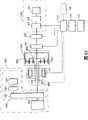
图1为本发明的系统方块图。Fig. 1 is a system block diagram of the present invention.
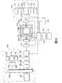
图2为本发明分离式串并联混合式双动力驱动系统的分离式实施例方块图之一。Fig. 2 is one of the block diagrams of the separated embodiment of the separated series-parallel hybrid dual-power drive system of the present invention.
图3为本发明分离式串并联混合式双动力驱动系统的分离式实施例方块图之二。Fig. 3 is the second block diagram of the separated embodiment of the separated series-parallel hybrid dual-power drive system of the present invention.
图4为本发明分离式串并联混合式双动力驱动系统的分离式实施例方块图之三。Fig. 4 is the third block diagram of the separated embodiment of the separated series-parallel hybrid dual-power driving system of the present invention.
图5为本发明分离式串并联混合式双动力驱动系统的分离式实施例方块图之四。Fig. 5 is the fourth block diagram of the separated embodiment of the separated series-parallel hybrid dual-power drive system of the present invention.
图6为本发明分离式串并联混合式双动力驱动系统的分离式实施例方块图之五。Fig. 6 is the fifth block diagram of the separated embodiment of the separated series-parallel hybrid dual-power drive system of the present invention.
图7为本发明分离式串并联混合式双动力驱动系统的分离式实施例方块图之六。Fig. 7 is the sixth block diagram of the separated embodiment of the separated series-parallel hybrid dual-power drive system of the present invention.
图8为本发明分离式串并联混合式双动力驱动系统的分离式实施例方块图之七。Fig. 8 is the seventh block diagram of the separated embodiment of the separated series-parallel hybrid dual-power drive system of the present invention.
图9为本发明分离式串并联混合式双动力驱动系统的分离式实施例方块图之八。Fig. 9 is the eighth block diagram of the separated embodiment of the separated series-parallel hybrid dual-power drive system of the present invention.
图10为本发明分离式串并联混合式双动力驱动系统的分离式实施例方块图之九。Fig. 10 is the ninth block diagram of the separated embodiment of the separated series-parallel hybrid dual-power driving system of the present invention.
图11为本发明分离式串并联混合式双动力驱动系统的分离式实施例方块图之十。Fig. 11 is the tenth block diagram of the separated embodiment of the separated series-parallel hybrid dual-power drive system of the present invention.
图12为本发明分离式串并联混合式双动力驱动系统的分离式实施例方块图之十一。Fig. 12 is the eleventh block diagram of the separated embodiment of the separated series-parallel hybrid dual-power drive system of the present invention.
图13为本发明分离式串并联混合式双动力驱动系统的分离式实施例方块图之十二。Fig. 13 is the twelfth block diagram of the separated embodiment of the separated series-parallel hybrid dual-power driving system of the present invention.
图14为本发明分离式串并联混合式双动力驱动系统的分离式实施例方块图之十三。Fig. 14 is the thirteenth block diagram of the separated embodiment of the separated series-parallel hybrid dual-power drive system of the present invention.
图15为本发明分离式串并联混合式双动力驱动系统的分离式实施例方块图之十四。Fig. 15 is the fourteenth block diagram of the separated embodiment of the separated series-parallel hybrid dual-power drive system of the present invention.
图16为本发明分离式串并联混合式双动力驱动系统的分离式实施例方块图之十五。Fig. 16 is the fifteenth block diagram of the separated embodiment of the separated series-parallel hybrid dual-power driving system of the present invention.
图17为本发明串并联混合式双动力驱动系统的分离式实施例方块图之十六。Fig. 17 is the sixteenth block diagram of the separated embodiment of the series-parallel hybrid dual-power drive system of the present invention.
图18为本发明分离式串并联混合式双动力驱动系统的分离式实施例方块图之十七。Fig. 18 is the seventeenth block diagram of the separated embodiment of the separated series-parallel hybrid dual-power drive system of the present invention.
图19为本发明分离式串并联混合式双动力驱动系统的分离式实施例方块图之十八。Fig. 19 is the eighteenth block diagram of the separated embodiment of the separated series-parallel hybrid dual-power driving system of the present invention.
图20为本发明串并联混合式双动力驱动系统的分离式实施例方块图之十九。Fig. 20 is the nineteenth block diagram of the separated embodiment of the series-parallel hybrid dual-power drive system of the present invention.
图21为本发明分离式串并联混合式双动力驱动系统的分离式实施例方块图之二十。Fig. 21 is the twentieth block diagram of the separated embodiment of the separated series-parallel hybrid dual-power driving system of the present invention.
图22为本发明以差动轮组取代图16游星轮组的分离式实施例方块图之二十一。Fig. 22 is the twenty-first block diagram of the separated embodiment of the present invention which replaces the planetary wheel set in Fig. 16 with a differential wheel set.
图23为本发明以差动轮组取代图17游星轮组的分离式实施例方块图之二十二。Fig. 23 is the twenty-second block diagram of the separated embodiment of the present invention which replaces the planetary wheel set in Fig. 17 with a differential wheel set.
图24为本发明以差动轮组取代图18游星轮组的分离式实施例方块图之二十三。Fig. 24 is the twenty-third block diagram of the separated embodiment of the present invention which replaces the planetary wheel set in Fig. 18 with a differential wheel set.
图25为本发明以差动轮组取代图19游星轮组的分离式实施例方块图之二十四。Fig. 25 is the twenty-fourth block diagram of the separated embodiment of the present invention which replaces the planetary wheel set in Fig. 19 with a differential wheel set.
图26为本发明以差动轮组取代图20游星轮组的分离式实施例方块图之二十五。Fig. 26 is the twenty-fifth block diagram of the separated embodiment of the present invention which replaces the planetary wheel set in Fig. 20 with a differential wheel set.
图27为本发明以差动轮组取代图21游星轮组的分离式实施例方块图之二十六。Fig. 27 is the twenty-sixth block diagram of the separated embodiment of the present invention which replaces the planetary wheel set in Fig. 21 with a differential wheel set.
图28为本发明以双动型电机单元取代图16游星轮组的分离式实施例方块图之二十七。Fig. 28 is the twenty-seventh block diagram of the separated embodiment in which the double-acting motor unit replaces the planetary wheel set in Fig. 16 according to the present invention.
图29为本发明以双动型电机单元取代图16游星轮组的分离式实施例方块图之二十八。Fig. 29 is the twenty-eighth block diagram of the separated embodiment of the present invention in which the planetary wheel set in Fig. 16 is replaced by a double-acting motor unit.
图30为本发明以双动型电机单元取代图18游星轮组的分离式实施例方块图之二十九。Fig. 30 is the twenty-ninth block diagram of the separated embodiment of the present invention in which the planetary wheel set in Fig. 18 is replaced by a double-acting motor unit.
图31为本发明以双动型电机单元取代图19游星轮组的分离式实施例方块图之三十。Fig. 31 is the thirtieth block diagram of the split embodiment in which the double-acting motor unit replaces the planetary wheel set in Fig. 19 according to the present invention.
图32为本发明以双动型电机单元取代图20游星轮组的分离式实施例方块图之三十一。Fig. 32 is the thirty-first block diagram of the separated embodiment in which the double-acting motor unit replaces the planetary wheel set in Fig. 20 according to the present invention.
图33为本发明以双动型电机单元取代图21游星轮组的分离式实施例方块图之三十二。Fig. 33 is the block diagram No. 32 of the separated embodiment of the present invention, which replaces the planetary wheel set in Fig. 21 with a double-acting motor unit.
图34为本发明主动回转动力源输出端设有前置驱动单元的系统方块示意图之一。Fig. 34 is one of the system block diagrams in which the output end of the active rotary power source is provided with a pre-drive unit according to the present invention.
图35为本发明主动回转动力源输出端设有前置驱动单元的系统方块示意图之二。Fig. 35 is the second schematic block diagram of the system in which the output end of the active rotary power source is provided with a pre-drive unit in the present invention.
图36为本发明主动回转动力源输出端设有前置驱动单元的系统方块示意图之三。Fig. 36 is the third schematic block diagram of the system in which the output end of the active rotary power source is provided with a pre-drive unit in the present invention.
图37为本发明主动回转动力源输出端设有前置驱动单元的系统方块示意图之四。Fig. 37 is the fourth schematic block diagram of the system in which the output end of the active rotary power source is provided with a pre-drive unit according to the present invention.
图38为本发明主动回转动力源输出端设有前置驱动单元的系统方块示意图之五。Fig. 38 is the fifth schematic block diagram of the system in which the output end of the active rotary power source is provided with a pre-drive unit according to the present invention.
图39为本发明主动回转动力源输出端设有前置驱动单元的系统方块示意图之六。Fig. 39 is the sixth schematic block diagram of the system in which the output end of the active rotary power source is provided with a pre-drive unit according to the present invention.
图40为本发明主动回转动力源输出端设有前置驱动单元的系统方块示意图之七。Fig. 40 is the seventh block diagram of the system in which the output end of the active rotary power source is provided with a pre-drive unit in the present invention.
图41为本发明主动回转动力源输出端设有前置驱动单元的系统方块示意图之八。Fig. 41 is the eighth schematic block diagram of the system in which the output end of the active rotary power source is provided with a pre-drive unit in the present invention.
图42为本发明主动回转动力源输出端设有前置驱动单元的系统方块示意图之九。Fig. 42 is the ninth block diagram of the system in which the output end of the active rotary power source is provided with a pre-drive unit in the present invention.
图43为本发明主动回转动力源输出端设有前置驱动单元的系统方块示意图之十。Fig. 43 is the tenth block diagram of the system in which the output end of the active rotary power source is provided with a pre-drive unit according to the present invention.
图44为本发明主动回转动力源输出端设有前置驱动单元的系统方块示意图之十一。Fig. 44 is the eleventh block diagram of the system in which the output end of the active rotary power source is provided with a pre-drive unit in the present invention.
图45为本发明主动回转动力源输出端设有前置驱动单元的系统方块示意图之十二。Fig. 45 is the twelveth schematic block diagram of the system in which the output end of the active rotary power source is provided with a pre-drive unit in the present invention.
图46为本发明主动回转动力源输出端设有前置驱动单元的系统方块示意图之十三。Fig. 46 is the thirteenth block diagram of the system in which the output end of the active rotary power source is provided with a pre-drive unit according to the present invention.
图47为本发明主动回转动力源输出端设有前置驱动单元的系统方块示意图之十四。Fig. 47 is the fourteenth schematic block diagram of the system in which the output end of the active rotary power source is provided with a pre-drive unit in the present invention.
图48为本发明主动回转动力源输出端设有前置驱动单元的系统方块示意图之十五。Fig. 48 is the fifteenth block diagram of the system in which the output end of the active rotary power source is provided with a pre-drive unit in the present invention.
图49为本发明主动回转动力源输出端设有前置驱动单元的系统方块示意图之十六。Fig. 49 is the sixteenth block diagram of the system in which the output end of the active rotary power source is provided with a pre-drive unit according to the present invention.
图50为本发明主动回转动力源输出端设有前置驱动单元的系统方块示意图之十七。Fig. 50 is the seventeenth block diagram of the system in which the output end of the active rotary power source is provided with a pre-drive unit according to the present invention.
图51为本发明主动回转动力源输出端设有前置驱动单元的系统方块示意图之十八。Fig. 51 is the eighteenth block diagram of the system in which the output end of the active rotary power source is provided with a pre-drive unit in the present invention.
具体实施方式Detailed ways
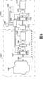
图1所示为本发明的系统方块图,为由主动回转动力源与第一电机单元及第二电机单元,经所选择性配置的离合器,及选择性配置的变速单元作系统性联结的形态。Fig. 1 is a system block diagram of the present invention, which is a form in which the active rotary power source is systematically connected with the first motor unit and the second motor unit, via a selectively configured clutch, and a selectively configured speed change unit .
图1所示的分离式串并联混合式双动力驱动系统,主要为藉由主动回转动力源、各种电机单元、传动单元、变速单元、离合器、驱动控制单元、中央控制单元、储放电装置、或辅助储放电装置、或电能驱动的负载等具特定功能的总成单元或装置所构成,其主要构成含:The separated series-parallel hybrid dual-power drive system shown in Figure 1 is mainly composed of active rotary power sources, various motor units, transmission units, transmission units, clutches, drive control units, central control units, storage and discharge devices, Or auxiliary storage and discharge devices, or electric energy-driven loads and other assembly units or devices with specific functions, its main components include:
——主动回转动力源100:为由至少一个公知的各种内燃引擎、外燃引擎、涡轮引擎、或其它物理效应致动的回转动能动力源所构成,主动回转动力源的转部可选择为直接耦合于第一电机单元101,或经由依需要作选择性设置的变速单元109、或选择性设置的传动单元129,或经由依需要作选择性设置的离合器102,再耦合于第一电机单元101的转部;——Active rotary power source 100: it is composed of at least one rotary kinetic power source actuated by various known internal combustion engines, external combustion engines, turbine engines, or other physical effects, and the rotary part of the active rotary power source can be selected In order to be directly coupled to the
——第一电机单元101:为由至少一个具发电机功能,或具有可切换作发电机功能或马达功能的交流或直流、无刷或有刷、同步或异步的回转电机所构成,若第一驱动系统1001依需要选择性设有第二电机单元103时,则由第一电机单元101的转部,经离合器112或差动轮组或游星轮组,耦合于第二电机单元103;或经离合器112及依需要作选择性设置的变速单元109,耦合于第二电机单元103的转部;——The first motor unit 101: it is composed of at least one AC or DC, brushless or brushed, synchronous or asynchronous rotary motor with generator function, or with switchable generator function or motor function. When a
——第二电机单元103:为由至少一个具马达功能,或具有可切换作马达功能或发电机功能的交流、或直流,无刷、或有刷,同步、或异步的回转电机所构成供作为第二驱动系统1002的回转动力源,第二电机单元103的转部输出端可选择为直接输出回转动能以驱动负载,或经依需要作选择性设置的离合器122,或经依需要作选择性设置的变速单元109以输出回转动能驱动负载;——The second motor unit 103: it is composed of at least one AC, or DC, brushless, or brushed, synchronous, or asynchronous rotary motor with motor function, or with switchable motor function or generator function. As the rotary power source of the
若系统选择设置离合器132时,则第二电机单元103的输入端可依需要选择性直接、或经变速单元、或可差动变速单元109联结于离合器132;If the system chooses to set the clutch 132, the input end of the
——离合器102:为藉人力、或机械力、或离心力、或气压、或油压的流力、或电磁力等所操控的离合器、或单向离合器(single way clutch)、或可调控的扭力耦合器或其它用以供传输或切断机械回转动能的传输装置所构成;离合器102为直接或经传动单元129,而耦合联结于主动回转动力源100的转部与第一电机单元101之间,此项离合器102并可依需要选择性设置一个或一个以上或不设置;——Clutch 102: a clutch controlled by manpower, or mechanical force, or centrifugal force, or air pressure, or oil pressure flow force, or electromagnetic force, or a one-way clutch (single way clutch), or an adjustable torque A coupler or other transmission devices for transmitting or cutting off mechanical rotary kinetic energy; the clutch 102 is directly or via a
——离合器112:为藉人力、或机械力、或离心力、或气压、或油压的流力、或电磁力等所操控的离合器、或单向离合器(single way clutch)、或可调控的扭力耦合器或其它用以供传输或切断机械回转动能的传输装置所构成;上述离合器112为耦合联结于第二电机单元103的转部与主动回转动力源100输出端之间,或耦合联结于第二电机单元103与第一电机单元101的转部之间,离合器112可为一个或一个以上;——clutch 112: a clutch controlled by manpower, or mechanical force, or centrifugal force, or air pressure, or oil pressure flow force, or electromagnetic force, or a one-way clutch (single way clutch), or an adjustable torque A coupler or other transmission devices used to transmit or cut off mechanical rotary kinetic energy; the above-mentioned
——离合器122:为藉人力、或机力、或离心力、或气压、或油压的流力、或电磁力等所操控的离合器、或单向离合器(single way clutch)、或可调控的扭力耦合器或其它用以供传输或切断机械回转动能的传输装置所构成;上述离合器122为耦合联结于负载120的输入端与第二电机单元103转部之间,离合器122为可依需要选择性设置一个或一个以上或不设置,或由耦合联结于负载120输入端的变速装置109的空档功能、或可调控的扭力耦合功能以取代离合器122的功能;——Clutch 122: a clutch controlled by manpower, or mechanical force, or centrifugal force, or air pressure, or oil pressure flow force, or electromagnetic force, or a one-way clutch (single way clutch), or an adjustable torque A coupler or other transmission devices for transmitting or cutting off mechanical rotational energy; the above-mentioned
——离合器132:为藉人力、或机力、或离心力、或气压、或油压的流力、或电磁力等所操控的离合器、或单向离合器(single way clutch)、或可调控的扭力耦合器或其它用以供传输或切断机械回转动能的传输装置所构成;上述离合器132为耦合联结于主动回转动力源100转部所耦合联结的传动单元129,与第二驱动系统1002的第二电机单元103转部之间;或依需要选择耦合联结于第一驱动系统1001中,供产生或传输主动回转动能的动力系统(Power Tra in)的回转机构,与第二驱动系统1002中供产生或传输主动回转功能的回转机构之间;以供操控第一驱动系统1001与第二驱动系统1002间回转动能的传输或切断,或于系统设有两组或两组以上的第二驱动系统1002时,供设置于各组第二驱动系统1002之间,以作回转动能的传输或切断;离合器132可依需要选择性设置一个或一个以上或不设置;——Clutch 132: a clutch controlled by manpower, or mechanical force, or centrifugal force, or air pressure, or oil pressure flow force, or electromagnetic force, or a one-way clutch (single way clutch), or an adjustable torque The coupling or other transmission devices for transmitting or cutting off the mechanical rotary kinetic energy; the above-mentioned
——传动单元129:为由各种固定速比、或自动、或半自动、或手排的多段或无段变速传动装置、或差动轮组、或周转轮组、流体扭力耦合器、或带式无段变速器(CVT)、或其它公知变速装置所构成并可依需要为具有空档、倒档等功能,供依需要选择耦合联结于主动回转动力源100的转部,其输出端为可供直接或经变速单元109或离合器102以驱动第一电机单元101,或供驱动第一驱动系统1001的负载120,或供耦合联结离合器132的输入端;此项传动单元129可依系统需要选择设置或不设置;此项传动单元129亦可由游星轮组801、或周转轮组1030、或双动型电机单元1040所取代;——Transmission unit 129: a multi-stage or stepless speed change transmission device with various fixed speed ratios, automatic, semi-automatic, or manual, or a differential wheel set, or an epicyclic wheel set, a fluid torsion coupling, or a belt Type continuously variable transmission (CVT) or other known speed change devices and can have neutral gear, reverse gear and other functions as required, for the rotating part that is selectively coupled and connected to the active
——变速单元109:为由各种固定速比、或自动、或半自动、或手排的多段或无段变速传动装置、或差动轮组、或周转轮组、流体扭力耦合器、或带式无段变速器(CVT)、或其它公知变速装置所构成并可依需要为具有倒档、空档等功能,供依需要选择耦合联结于主动回转动力源100的转部与离合器102之间,或选择设置于离合器102与第一电机单元101转部之间,或选择设置于第一电机单元101转部与离合器112转部之间,或选择设置于离合器112转部与第二电机单元103转部之间,或选择设置于第二电机单元103转部与离合器122转部之间,或选择设置于离合器122转部与负载120转部之间;上述变速单元109可依需要选择设置或不设置;——Transmission unit 109: it is a multi-stage or stepless speed change transmission device with various fixed speed ratios, automatic, semi-automatic, or manual, or a differential wheel set, or an epicyclic wheel set, a fluid torsion coupling, or a belt Type continuously variable transmission (CVT) or other known speed change devices and can have functions such as reverse gear and neutral gear as required, for selective coupling between the rotating part of the active
——驱动控制单元104:为由机电或固态电路所构成,供于系统作串联式混合动力系统运作,设置于第一驱动系统1001的第一电机单元101作发电机功能运转时,操控其发电输出的电能以驱动设置于第一驱动系统1001或第二驱动系统1002的第二电机单元103、及对储放电装置106充电,或操控对上述两种发电输出功能其中之一的运作;或供操控储放电装置106的电能,以驱动作为马达功能运转的第一电机单元101及第二电机单元103或驱动上述电机单元其中的部分电机单元,藉操控其驱动电压、电流、极性(直流时)、频率及相序(交流时),以操控电机单元的运转转向、转速、扭力、及异常保护;或于设置于第一驱动系统1001的第一电机单元101及设置于第一驱动系统1001或第二驱动系统1002的第二电机单元103或其中部分电机单元,接受负载逆向驱动而作发电功能运转时,藉操控所输往储放电装置106的充电电能,或输往其它负载的供电电能,以使电机单元作再生发电制动功能的运转;此项装置可依需要选择设置或不设置;——Drive control unit 104: composed of electromechanical or solid-state circuits, for the system to operate as a series hybrid power system, when the first motor unit 101 installed in the first drive system 1001 operates as a generator, it controls its power generation The output electric energy is used to drive the second motor unit 103 installed in the first drive system 1001 or the second drive system 1002, and to charge the storage and discharge device 106, or to control the operation of one of the above two power generation and output functions; or to supply Manipulate the electric energy of the storage and discharge device 106 to drive the first motor unit 101 and the second motor unit 103 that operate as a motor function or drive some of the motor units in the motor unit, by controlling its driving voltage, current, polarity (dc time ), frequency and phase sequence (in AC), to control the motor unit’s steering, speed, torque, and abnormal protection; or in the first motor unit 101 and the first drive system 1001 Or the second motor unit 103 of the second drive system 1002 or some of the motor units accept the reverse drive of the load to perform the function of generating electricity, by controlling the charging power delivered to the storage and discharge device 106, or the power supply delivered to other loads , so that the motor unit can operate with regenerative braking function; this device can be set or not set according to needs;
——中央控制单元105:为由固态、或机电式组件、或芯片及相关运作软件所构成,供接受操控接口107的操控,以操控此项分离式串并联混合式双动力驱动系统作相关功能运作,特别是相关系统运作中燃料耗用及污染调控的最佳化,为泛指系统作串联式混合动力系统运作或并联式混合动力系统运作时,使引擎运转于耗用燃料较低,但可相对获得输出功率较高的较节省燃料运转区域的运转速度范围,以达最佳制动燃料消耗比量(Brake Specific Fuel Consumption);以及藉操控驱动控制单元104以操控设置于第一驱动系统1001的第一电机单元101及设置于第一驱动系统1001或第二驱动系统1002的第二电机单元103、及储放电装置106之间作相对功能的运作,以及操控系统内各单元间的回授监控及互动的运转;此项装置可依需要选择设置或不设置;——Central Control Unit 105: It is composed of solid-state, or electromechanical components, or chips and related operating software, for receiving the control of the
——储放电装置106:为由各式可充放电蓄电瓶、或超电容、或其它可充放电蓄电装置所构成,此项储放电装置可依系统需要作选择性设置或不设置;——Storage and discharge device 106: It is composed of various rechargeable and discharge storage batteries, or supercapacitors, or other rechargeable and discharge storage devices. This storage and discharge device can be selectively installed or not installed according to the needs of the system;
——操控接口107:为由固态、或机电式组件、或芯片、及相关软件所构成,供接受人工或操控信号的输入,以操控此项分离式串并联混合式双动力驱动系统的运作;此项操控接口107可依需要选择设置或不设置;- Control interface 107: composed of solid-state or electromechanical components, or chips, and related software, for receiving manual or control signal input to control the operation of the separated series-parallel hybrid dual-power drive system; This
——辅助储放电装置110:为由各式可充放电蓄电瓶、或超电容、或飞轮蓄能的储放电装置或其它可充放电蓄电装置所构成,其电能经激活开关111的控制,以驱动作为主动回转动力源100的引擎组的起动马达121,进而直接或经传动装置119激活引擎组,或对周边配备或其它电能驱动的负载130供电;此项辅助储放电装置110及激活开关111及起动马达121可依需要选择设置或不设置;——Auxiliary storage and discharge device 110: it is composed of various rechargeable and dischargeable storage batteries, or ultracapacitors, or flywheel energy storage and discharge devices or other rechargeable and dischargeable storage devices, and its electric energy is controlled by the
——电能驱动的负载130:为可由前述第一电机单元101的发电电能、或第二电机单元103作为发电机功能运转时的发电电能,或储放电装置106、或辅助储放电装置110的电能为电源的周边负载;此项电能驱动的负载130可依需要选择设置或不设置;——The
藉上述系统的运作,其输出的回转动能可供驱动陆上、或水上、或空中载具及产业设备等需接受输入回转机械动能的负载。Through the operation of the above system, the output rotary kinetic energy can be used to drive loads that need to receive the input rotary mechanical kinetic energy, such as land, water, or aerial vehicles and industrial equipment.
此项分离式串并联混合式双动力驱动系统,若以引擎构成主动回转动力源,系统具有以下全部或部份运作功能,含:This separate series-parallel hybrid dual-power drive system, if the engine constitutes the active rotary power source, the system has all or part of the following operating functions, including:
——藉由引擎动力的回转动能驱动设置于第一驱动系统1001的负载120,或驱动设置于第二驱动系统1002的负载120或同时驱动前述负载的部份或全部;——drive the
——于系统作串联式混合动力系统的运作时,可藉由操控引擎由低转速至高转速运转,或作设定转速运转以驱动设置于第一驱动系统1001的第一电机单元101作发电机功能运转,若系统未设置储放电装置106,则以第一电机单元101发电的电能,供驱动设置于第一驱动系统1001或第二驱动系统1002的第二电机单元103作马达功能运转,以输出回转动能驱动负载120;若系统设置储放电装置106,则于负载较轻时,由设置于第一驱动系统1001的第一电机单元101所发电的电能,驱动设置于第一驱动系统1001或第二驱动系统1002的第二电机单元103,并同时对储放电装置106充电,于重负载时,则由设置于第一驱动系统1001的第一电机单元101的发电电能,与储放电装置106的电能同时驱动设置于第一驱动系统1001、或第二驱动系统1002的第二电机单元103,以输出回转动能驱动负载120,并调控引擎运作于较高能源效率的设定转速运转条件,以节省燃料及降低污染,前述引擎设定转速运转的定义,为泛指系统作串联式混合动力系统运作或并联式混合动力系统运作时,使引擎运转于耗用燃料较低,但可相对获得输出功率较高的较节省燃料运转区域的运转速度范围,以达最佳制动燃料消耗比量(Brake Specific Fuel Consumption);或于系统选择加设储放电装置106时,则进一步可藉引擎所驱动第一电机单元101的发电电能对储放电装置106作充电,或由储放电装置106的电能与第一电机单元101的发电电能,共同驱动第二电机单元103作电动机功能输出驱动负载120,以调控引擎运作于较高能源效率的定速运转条件,前述引擎设定转速运转的定义,为泛指系统作串联式混合动力系统运作或并联式混合动力系统运作时,使引擎运转于耗用燃料较低,但可相对获得输出功率较高的较节省燃料运转区域的运转速度范围,以达最佳制动燃料消耗比量(Brake Specific Fuel Consumption);——When the system is operating as a series hybrid system, the engine can be operated from a low speed to a high speed, or at a set speed to drive the first motor unit 101 installed in the first drive system 1001 as a generator Functional operation, if the system is not provided with the storage and discharge device 106, then the electric energy generated by the first motor unit 101 is used to drive the second motor unit 103 installed in the first drive system 1001 or the second drive system 1002 for motor function operation, so as to Output rotary kinetic energy to drive the load 120; if the system is equipped with a storage and discharge device 106, when the load is light, the electric energy generated by the first motor unit 101 installed in the first drive system 1001 drives the first drive system 1001 Or the second motor unit 103 of the second drive system 1002, and simultaneously charge the storage and discharge device 106, and when the load is heavy, the electric energy generated by the first motor unit 101 arranged on the first drive system 1001, and the storage and discharge device The electric energy of 106 simultaneously drives the second motor unit 103 installed in the first drive system 1001 or the second drive system 1002 to output rotary kinetic energy to drive the load 120, and regulate the engine to operate at a set speed with higher energy efficiency. , in order to save fuel and reduce pollution, the above-mentioned definition of engine running at a set speed generally refers to when the system operates as a series hybrid system or a parallel hybrid system, the engine runs at a lower fuel consumption, but can be relatively Obtain the operating speed range of the relatively fuel-saving operating area with higher output power to achieve the best brake fuel consumption ratio (Brake Specific Fuel Consumption); or when the system chooses to add a storage and
——于系统选择加设储放电装置106,则于系统作并联式混合动力系统的运作时,藉由储放电装置106的电能,驱动设置于第一驱动系统1001的第一电机单元101及设置于第一驱动系统1001或第二驱动系统1002的第二电机单元103或两者其中之一作马达功能运转,并与引擎动能共同驱动负载120,或于系统负载较轻时,引擎的回转动能除驱动负载120外,并可同时驱动设置于第一驱动系统1001的第一电机单元101及设置于第一驱动系统1001或第二驱动系统1002的第二电机单元103或其中部分第二电机单元103,以对储放电装置106充电或对其他电能驱动的负载130供电,于重载时则由储放电装置106的电能,驱动设置于第一驱动系统1001的第一电机单元101、及设置于第一驱动系统1001或第二驱动系统1002的第二电机单元103或其中部分第二电机单元103,与引擎所输出的回转动能共同驱动负载;——If the system chooses to add a storage and
——藉由储放电装置106的电能驱动设置于第一驱动系统1001的第一电机单元101、及设置于第一驱动系统1001或第二驱动系统1002的第二电机单元103或其中部分第二电机单元103,作马达功能运转驱动负载120;——Drive the
——藉由引擎动力驱动设置于第一驱动系统1001的第一电机单元101、及设置于第一驱动系统1001或第二驱动系统1002的第二电机单元103或其中部分第二电机单元103,作发电机功能运转,其发电电能供对储放电装置充电106或对其他电能驱动的负载130供电;——driving the
——藉由负载120逆向驱动设置于第一驱动系统1001的第一电机单元101、及设置于第一驱动系统1001或第二驱动系统1002的第二电机单元103或其中部分第二电机单元103,作再生发电的发电机功能运转,其发电的电能供对储放电装置106充电或对其他电能驱动的负载130供电;——Reverse driving the
——藉由引擎的机械阻尼作为制动刹车功能,或于设有储放电装置106时,同时由设置于第一驱动系统1001的第一电机单元101及设置于第一驱动系统1001或第二驱动系统1002的第二电机单元103或其中部分第二电机单元103,作为发电机功能运转,以对储放电装置106充电或对其他电能驱动的负载130供电,以产生再生发电制动功能;——Using the mechanical damping of the engine as a braking function, or when the storage and
——由储放电装置106驱动设置于第一驱动系统1001的第一电机单元101、及设置于第一驱动系统1001或第二驱动系统1002的第二电机单元103或其中部分第二电机单元103,作马达功能激活引擎;——The
——藉由操控离合器132,于闭合时供传输耦合联结于主动回转动力源100的传动单元129与第二驱动系统1002间的回转动能,或传输第一驱动系统1001与第二驱动系统1002间的回转动能,或传输两组或两组以上第二驱动系统间的回转动能;于脱离时切断上述回转动能的传输;——By manipulating the clutch 132, when it is closed, it is used to transmit the rotary kinetic energy between the
为求详述申请案的应用,以下图2~图39的实施例,为以上述系统及功能为基础的代表性实施例,相同原理的其它应用例并不以此为限,为求叙述简化,以下图2~图39实施例为将图1所示的系统省略变速单元109、辅助储放电装置110、激活开关111、起动马达121、中央控制单元105、操控接口107,而以引擎作为主动回转动力源100并保留第一电机单元101、第二电机单元103、离合器102、112、122、132、驱动控制单元104、及可选择性设置储放电装置106、电能驱动的负载130所构成,以供驱动负载120。In order to describe the application of the application in detail, the embodiments in Figures 2 to 39 below are representative embodiments based on the above-mentioned systems and functions, and other application examples of the same principle are not limited to this, in order to simplify the description 2 to 39 below, the system shown in FIG. 1 omits the
图2~图51为以本发明图1所示系统为基础的各种驱动系统实施例,个别实施例具有以下运转功能或部分功能,包括:Figures 2 to 51 are various drive system embodiments based on the system shown in Figure 1 of the present invention, and individual embodiments have the following operating functions or partial functions, including:
——系统功能1:系统为不设置储放电装置106,而作串联式混合动力系统功能的运作,无论主动回转动力源100的回转动能为经第一驱动系统1001驱动所属负载120的状态,或为不驱动第一驱动系统1001所属负载120的状态,系统皆可藉由人工操控、或藉由中央控制单元105及驱动控制单元104所构成控制系统作操控,由主动回转动力源100的回转动能驱动第一电机单元101作发电机功能运转,其发电的电能供驱动设置于第一驱动系统1001的第二电机单元103,作电动机功能运转以驱动所属负载120;——System function 1: The system is not provided with the storage and
——系统功能2:系统为不设置储放电装置106,而作串联式混合动力系统功能的运作,无论主动回转动力源100的回转动能为经第一驱动系统1001驱动所属负载120的状态,或为不驱动第一驱动系统1001所属负载120的状态,系统皆可藉由人工操控、或藉由中央控制单元105及驱动控制单元104所构成控制系统作操控,由主动回转动力源100的回转动能驱动第一电机单元101作发电机功能运转,其发电的电能供驱动设置于第二驱动系统1002的第二电机单元103作电动机功能运转以驱动所属负载120;——System function 2: The system is not provided with the storage and
——系统功能3:系统为不设置储放电装置106,而作串联式混合动力系统功能的运作,无论主动回转动力源100的回转动能为经第一驱动系统1001驱动所属负载120的状态,或为不驱动第一驱动系统1001所属负载120的状态,系统皆可藉由人工操控、或藉由中央控制单元105及驱动控制单元104所构成控制系统作操控,由主动回转动力源100的回转动能驱动第一电机单元101作发电机功能运转,其发电的电能供同时驱动第一驱动系统1001及第二驱动系统1002的第二电机单元103作电动机功能运转以驱动所属负载120;——System function 3: The system does not set the storage and
——系统功能4:系统为设有储放电装置106,而作串联式混合动力系统功能的运作,无论主动回转动力源100的回转动能为经第一驱动系统1001驱动所属负载120的状态,或为不驱动第一驱动系统1001所属负载120的状态,系统皆可藉由人工操控、或藉由中央控制单元105及驱动控制单元104所构成控制系统作操控,由主动回转动力源100的回转动能驱动第一电机单元101作发电机功能运转,其发电的电能可供对储放电装置106充电,或对其他由电能驱动的负载130(含外接不特定负载)供电,以及供驱动设置于第一驱动系统1001(含所属子单元如前置驱动单元1000)的电机单元103作电动机功能运转,以驱动所属负载120;——System function 4: The system is equipped with a storage and
——系统功能5:系统为设有储放电装置106,而作串联式混合动力系统功能的运作,无论主动回转动力源100的回转动能为经第一驱动系统1001驱动所属负载120的状态,或为不驱动第一驱动系统1001所属负载120的状态,系统皆可藉由人工操控、或藉由中央控制单元105及驱动控制单元104所构成控制系统作操控,由主动回转动力源100的回转动能驱动第一电机单元101作发电机功能运转,其发电的电能可供对储放电装置106充电,或对其他由电能驱动的负载130(含外接不特定负载)供电,以及供驱动设置于第二驱动系统1002的第二电机单元103作电动机功能运转,以驱动所属负载120;——System function 5: The system is equipped with a storage and
——系统功能6:系统为设有储放电装置106,而作串联式混合动力系统功能的运作,无论主动回转动力源100的回转动能为经第一驱动系统1001驱动所属负载120的状态,或为不驱动第一驱动系统1001所属负载120的状态,系统皆可藉由人工操控、或藉由中央控制单元105及驱动控制单元104所构成控制系统作操控,由主动回转动力源100的回转动能驱动第一电机单元101作发电机功能运转,其发电的电能可供对储放电装置106充电,或对其他由电能驱动的负载130(含外接不特定负载)供电,以及供同时驱动第一驱动系统1001及第二驱动系统1002的第二电机单元103作电动机功能运转,以驱动所属负载120;——System function 6: The system is equipped with a storage and
——系统功能7:系统为设有储放电装置106,而作串联式混合动力系统功能的运作,无论主动回转动力源100的回转动能为经第一驱动系统1001驱动所属负载120的状态,或为不驱动第一驱动系统1001所属负载120的状态,系统皆可藉由人工操控、或藉由中央控制单元105及驱动控制单元104所构成控制系统作操控,由主动回转动力源100的回转动能驱动第一电机单元101作发电机功能运转,其发电的电能与储放电装置106所输出的电能供驱动设置于第一驱动系统1001(含所属子单元如前置驱动单元1000)的电机单元103作电动机功能运转,以驱动所属负载120;——System function 7: The system is equipped with a storage and
——系统功能8:系统为设有储放电装置106,而作串联式混合动力系统功能的运作,无论主动回转动力源100的回转动能为经第一驱动系统1001驱动所属负载120的状态,或为不驱动第一驱动系统1001所属负载120的状态,系统皆可藉由人工操控、或藉由中央控制单元105及驱动控制单元104所构成控制系统作操控,由主动回转动力源100的回转动能驱动第一电机单元101作发电机功能运转,其发电的电能与储放电装置106所输出的电能供驱动第二驱动系统1002的电机单元103作电动机功能运转,以驱动所属负载120;——System function 8: The system is equipped with a storage and
——系统功能9:系统为设有储放电装置106,而作串联式混合动力系统功能的运作,无论主动回转动力源100的回转动能为经第一驱动系统1001驱动所属负载120的状态,或为不驱动第一驱动系统1001所属负载120的状态,系统皆可藉由人工操控、或藉由中央控制单元105及驱动控制单元104所构成控制系统作操控,由主动回转动力源100的回转动能驱动第一电机单元101作发电机功能运转,其发电的电能与储放电装置106所输出的电能供同时驱动第一驱动系统1001及第二驱动系统1002的第二电机单元103作电动机功能运转,以驱动所属负载120;——System function 9: The system is equipped with a storage and
——系统功能10:由作为主动回转动力源100的引擎回转动能驱动第一驱动系统1001所属负载120;——System function 10: drive the
——系统功能11:由作为主动回转动力源100的引擎回转动能驱动第二驱动系统1002所属负载120;——System function 11: drive the
——系统功能12:由作为主动回转动力源100的引擎回转动能同时驱动第一驱动系统1001的负载120及驱动第二驱动系统1002所属负载120;——System function 12: drive the
——系统功能13:藉由作为主动回转动力源100的引擎回转动能,驱动第一驱动系统1001的负载120,并由引擎回转动能驱动第一电机单元101作发电机功能运转,以对储放电装置106充电,或对其他电能驱动的负载130(含外接不特定负载)供电;——System function 13: drive the
——系统功能14:藉由作为主动回转动力源100的引擎回转动能,驱动第一驱动系统1001的负载120,并由引擎回转动能驱动设置于第一驱动系统1001或第二驱动系统1002的第二电机单元103作发电机功能运转,以对储放电装置106充电,或对其他电能驱动的负载130(含外接不特定负载)供电;——System function 14: Drive the
——系统功能15:藉由作为主动回转动力源100的引擎回转动能,驱动第一驱动系统1001的负载120,并由引擎回转动能驱动第一电机单元101作发电机功能运转,及同时驱动设置于第一驱动系统1001或第二驱动系统1002的第二电机单元103作发电机功能运转,以对储放电装置106充电,或对其他电能驱动的负载130(含外接不特定负载)供电;——system function 15: drive the
——系统功能16:藉由作为主动回转动力源100的引擎回转动能,驱动第二驱动系统1002的负载120,并由引擎回转动能驱动第一电机单元101作发电机功能运转,以对储放电装置106充电,或对其他电能驱动的负载130(含外接不特定负载)供电;- System Function 16: Drive the
——系统功能17:藉由作为主动回转动力源100的引擎回转动能,驱动第二驱动系统1002的负载120,并由引擎回转动能驱动设置于第一驱动系统1001或第二驱动系统1002的第二电机单元103作发电机功能运转,以对储放电装置106充电,或对其他电能驱动的负载130(含外接不特定负载)供电;——System function 17: Drive the
——系统功能18:藉由作为主动回转动力源100的引擎回转动能,驱动第二驱动系统1002的负载120,并由引擎回转动能驱动第一电机单元101作发电机功能运转,及同时驱动设置于第一驱动系统1001或第二驱动系统1002的第二电机单元103作发电机功能运转,以对储放电装置106充电,或对其他电能驱动的负载130(含外接不特定负载)供电;——system function 18: drive the
——系统功能19:藉由作为主动回转动力源100的引擎回转动能,驱动第一驱动系统1001的负载120,及同时驱动第二驱动系统1002的负载120,并由引擎回转动能驱动第一电机单元101作发电机功能运转,以对储放电装置106充电,或对其他电能驱动的负载130(含外接不特定负载)供电;——System function 19: Drive the
——系统功能20:藉由作为主动回转动力源100的引擎回转动能,驱动第一驱动系统1001的负载120,及同时驱动第二驱动系统1002的负载120,并由引擎回转动能驱动设置于第一驱动系统1001或第二驱动系统1002的第二电机单元103作发电机功能运转,以对储放电装置106充电,或对其他电能驱动的负载130(含外接不特定负载)供电;——System function 20: Drive the
——系统功能21:藉由作为主动回转动力源100的引擎回转动能,驱动第一驱动系统1001的负载120,及同时驱动第二驱动系统1002的负载120,并由引擎回转动能驱动第一电机单元101作发电机功能运转,及同时驱动设置于第一驱动系统1001或第二驱动系统1002的第二电机单元103作发电机功能运转,以对储放电装置106充电,或对其他电能驱动的负载130(含外接不特定负载)供电;——System function 21: Drive the
——系统功能22:由储放电装置106的电能,驱动设置于第一驱动系统1001或第二驱动系统1002的第二电机单元103作电动机功能运转,或同时驱动两者作电动机功能运转,以驱动第一驱动系统1001所属负载120;——System function 22: Drive the
——系统功能23:由储放电装置106的电能,驱动设置于第一驱动系统1001或第二驱动系统1002的第二电机单元103作电动机功能运转,或同时驱动两者作电动机功能运转,以驱动第二驱动系统1002所属负载120;——System function 23: Drive the
——系统功能24:由储放电装置106的电能,驱动设置于第一驱动系统1001或第二驱动系统1002的第二电机单元103作电动机功能运转,或同时驱动两者作电动机功能运转,以驱动第一驱动系统1001及第二驱动系统1002所属负载120;——System function 24: Drive the
——系统功能25:由储放电装置106的电能,驱动第一电机单元101作电动机功能运转,以驱动第一驱动系统1001所属负载120;——System function 25: Drive the
——系统功能26:由储放电装置106的电能,驱动第一电机单元101作电动机功能运转,以驱动第二驱动系统1002所属负载120;——System function 26: Drive the
——系统功能27:由储放电装置106的电能,驱动第一电机单元101作电动机功能运转,以驱动第一驱动系统1001及第二驱动系统1002所属负载120;——System function 27: Drive the
——系统功能28:由储放电装置106的电能,驱动第一电机单元101作电动机功能运转,或驱动设置于第一驱动系统1001或第二驱动系统1002的第二电机单元103作电动机功能运转,或同时驱动两者作电动机功能运转,以驱动第一驱动系统1001所属负载120;——System function 28: Drive the
——系统功能29:由储放电装置106的电能,驱动第一电机单元101作电动机功能运转,或驱动设置于第一驱动系统1001或第二驱动系统1002的第二电机单元103作电动机功能运转,或同时驱动两者作电动机功能运转,以驱动第二驱动系统1002所属负载120;——System function 29: Drive the
——系统功能30:由储放电装置106的电能,驱动第一电机单元101作电动机功能运转,或驱动设置于第一驱动系统1001或第二驱动系统1002的第二电机单元103作电动机功能运转,或同时驱动两者作电动机功能运转,以驱动第一驱动系统1001及第二驱动系统1002所属负载120;——System function 30: Drive the
——系统功能31:由储放电装置106电能,驱动设置于第一驱动系统的电机单元103作电动机功能运转以产生回转动能,与作为主动回转动力源100的引擎回转动能,共同驱动第一驱动系统1001所属负载120;——System function 31: the electrical energy of the storage and
——系统功能32:由储放电装置106电能,驱动设置于第二驱动系统1002的第二电机单元103作电动机功能运转以产生回转动能,与作为主动回转动力源100的引擎回转动能,共同驱动第二驱动系统1002所属负载120;——System function 32: the
——系统功能33:由储放电装置106的电能,驱动设置于第一驱动系统1001或第二驱动系统1002的第二电机单元103作电动机功能运转以产生回转动能,与作为主动回转动力源100的引擎回转动能,共同驱动第一驱动系统1001及第二驱动系统1002所属负载120;——System function 33: The
——系统功能34:由储放电装置106的电能,驱动第一电机单元101作电动机功能运转,供与作为主动回转动力源100的引擎回转动能,共同驱动第一驱动系统1001所属负载120;——System function 34: Drive the
——系统功能35:由储放电装置106的电能,驱动第一电机单元101作电动机功能运转以产生回转动能,与作为主动回转动力源100的引擎回转动能,共同驱动第二驱动系统1002所属负载120;——System function 35: The
——系统功能36:由储放电装置106的电能,驱动第一电机单元101作电动机功能运转,与作为主动回转动力源100的引擎回转动能,共同驱动第一驱动系统1001及第二驱动系统1002所属负载120;——System function 36: the electric energy of the storage and
——系统功能37:由储放电装置106的电能,驱动第一电机单元101作电动机功能运转,及同时驱动设置于第一驱动系统的电机单元103作电动机功能运转以产生回转动能,与作为主动动力源100的引擎回转动能,共同驱动第一驱动系统1001所属负载120;——System function 37: Drive the
——系统功能38:由储放电装置106的电能,驱动第一电机单元101作电动机功能运转,及同时驱动设置于第二驱动系统1002的第二电机单元103作电动机功能运转以产生回转动能,与作为主动回转动力源100的引擎回转动能,共同驱动第二驱动系统1002所属负载120;——System function 38: Drive the
——系统功能39:由储放电装置106的电能,驱动设置于第一驱动系统1001的第一电机单元101作电动机功能运转,及同时驱动设置于第一驱动系统1001或第二驱动系统1002的第二电机单元103作电动机功能运转以产生回转动能,与作为主动回转动力源100的引擎回转动能,共同驱动第一驱动系统1001及第二驱动系统1002所属负载120;——System function 39: Drive the
——系统功能40:由第一驱动系统1001所属的负载120牵动第一电机单元101作发电机功能运转,以对储放电装置106充电,或对其他电能驱动的负载130(含外接不特定负载)供电,以构成再生发电的动能回收制动刹车功能;——System function 40: the
——系统功能41:由第二驱动系统1002所属的负载120,逆向牵动第一电机单元101作发电机功能运转,以对储放电装置106充电,或对其他电能驱动的负载130(含外接不特定负载)供电,以构成再生发电的动能回收制动刹车功能;——System function 41: the
——系统功能42:由第一驱动系统1001及第二驱动系统1002所属的负载120,逆向牵动第一电机单元101作发电机功能运转,以对储放电装置106充电,或对其他电能驱动的负载130(含外接不特定负载)供电,以构成再生发电的动能回收制动刹车功能;——System function 42: The
——系统功能43:由第一驱动系统1001所属的负载,逆向牵动设置于第一驱动系统1001的第二电机单元103作发电机功能运转,以对储放电装置106充电,或对其他电能驱动的负载130(含外接不特定负载)供电,以构成再生发电的动能回收制动刹车功能;——System function 43: The load belonging to the
——系统功能44:由第二驱动系统1002所属的负载120,逆向牵动设置于第二驱动系统1002的第二电机单元103作发电机功能运转,以对储放电装置106充电,或对其他电能驱动的负载130(含外接不特定负载)供电,以构成再生发电的动能回收制动刹车功能;——System function 44: the
——系统功能45:由第一驱动系统1001及第二驱动系统1002所属的负载120,逆向牵动第一电机单元101作发电机功能运转,设置于第一驱动系统1001以及第二驱动系统1002的第二电机单元103作发电机功能运转,以对储放电装置106充电,或对其他电能驱动的负载130(含外接不特定负载)供电,以构成再生发电的动能回收制动刹车功能;——System function 45: the
——系统功能46:由第一驱动系统1001所属的负载120,逆向牵动第一电机单元101作发电机功能运转,以及逆向牵动设置于第一驱动系统1001的第二电机单元103作发电机功能运转,以对储放电装置106充电,或对其他电能驱动的负载130(含外接不特定负载)供电,以构成再生发电的动能回收制动刹车功能;——System function 46: the
——系统功能47:由第二驱动系统1002所属的负载120,逆向牵动第一电机单元101作发电机功能运转,以及逆向牵动设置于第二驱动系统1002的第二电机单元103作发电机功能运转,以对储放电装置106充电,或对其他电能驱动的负载130(含外接不特定负载)供电,以构成再生发电的动能回收制动刹车功能;——System function 47: the
——系统功能48:由第一驱动系统1001及第二驱动系统1002所属的负载120,逆向牵动第一电机单元101作发电机功能运转,以及逆向牵动设置于第一驱动系统1001及第二驱动系统1002的第二电机单元103作发电机功能运转,以对储放电装置106充电,或对其他电能驱动的负载130(含外接不特定负载)供电,以构成再生发电的动能回收制动刹车功能;——System function 48: the
——系统功能49:由作为主动回转源100的引擎的机械阻尼作为对负载120作制动刹车;——system function 49: use the mechanical damping of the engine as the
——系统功能50:由作为主动回转动力源100的引擎的机械阻尼,作为对第一驱动系统1001所属的负载120作制动刹车的运作,同时逆向牵动第一电机单元101作发电机功能运转,以对储放电装置106充电,或对其他电能驱动的负载130(含外接不特定负载)供电,以再生发电的阻尼对第一驱动系统1001所属负载120作制动刹车;——System function 50: The mechanical damping of the engine as the active
——系统功能51:由作为主动回转动力源100的引擎的机械阻尼,作为对第二驱动系统1002所属的负载120作制动刹车的运作,同时逆向牵动第一电机单元101作发电机功能运转,以对储放电装置106充电,或对其他电能驱动的负载130(含外接不特定负载)供电,以再生发电的阻尼对第二驱动系统1002所属的负载120作制动刹车;——System function 51: The mechanical damping of the engine as the active
——系统功能52:由作为主动回转动力源100的引擎的机械阻尼,作为对第一驱动系统1001及第二驱动系统1002所属的负载120作制动刹车的运作,同时逆向牵动第一电机单元101作发电机功能运转,以对储放电装置106充电,或对其他电能驱动的负载130(含外接不特定负载)供电,以再生发电的阻尼对第一驱动系统1001及第二驱动系统1002所属的负载120作制动刹车;——System function 52: The mechanical damping of the engine as the active
——系统功能53:由作为主动回转动力源100的引擎的机械阻尼,作为对第一驱动系统1001所属的负载120作制动刹车的运作,同时逆向牵动设置于第一驱动系统1001的第二电机单元103作发电机功能运转,以对储放电装置106充电,或对其他电能驱动的负载130(含外接不特定负载)供电,以再生发电的阻尼对第一驱动系统1001所属的负载120作制动刹车;——System function 53: The mechanical damping of the engine as the active
——系统功能54:由作为主动回转动力源100的引擎的机械阻尼,作为对第二驱动系统1002所属的负载120作制动刹车的运作,同时逆向牵动设置于第二驱动系统1002的第二电机单元103作发电机功能运转,以对储放电装置106充电,或对其他电能驱动的负载130(含外接不特定负载)供电,以再生发电的阻尼对第二驱动系统1002所属的负载120作制动刹车;——System function 54: The mechanical damping of the engine as the active
——系统功能55:由作为主动回转动力源100的引擎的机械阻尼,作为对第一驱动系统1001及第二驱动系统1002所属的负载120作制动刹车的运作,同时逆向牵动设置于第一驱动系统1001及第二驱动系统1002的第二电机单元103作发电机功能运转,以对储放电装置106充电,或对其他电能驱动的负载130(含外接不特定负载)供电,以再生发电的阻尼对第一驱动系统1001及第二驱动系统1002所属的负载120作制动刹车;——System function 55: The mechanical damping of the engine as the active
——系统功能56:由作为主动回转动力源100的引擎的机械阻尼,作为对第一驱动系统1001所属的负载120作制动刹车的运作,同时逆向牵动第一电机单元101作发电机功能运转,以及逆向牵动设置于第一驱动系统1001的第二电机单元103作发电机功能运转,以对储放电装置106充电,或对其他电能驱动的负载130(含外接不特定负载)供电,以再生发电的阻尼对第一驱动系统1001所属的负载120作制动刹车;——System function 56: The mechanical damping of the engine as the active
——系统功能57:由作为主动回转动力源100的引擎的机械阻尼,作为对第二驱动系统1002所属的负载120作制动刹车的运作,同时逆向牵动第一电机单元101作发电机功能运转,以及逆向牵动设置于第二驱动系统1002的第二电机单元103作发电机功能运转,以对储放电装置106充电,或对其他电能驱动的负载130(含外接不特定负载)供电,以再生发电的阻尼对第二驱动系统1002所属的负载120作制动刹车;——System function 57: The mechanical damping of the engine as the active
——系统功能58:由作为主动回转动力源100的引擎的机械阻尼,作为对第一驱动系统1001及第二驱动系统1002所属的负载120作制动刹车的运作,同时逆向牵动第一电机单元101作发电机功能运转,以及逆向牵动设置于第二驱动系统1002的第二电机单元103作发电机功能运转,以对储放电装置106充电,或对其他电能驱动的负载130(含外接不特定负载)供电,以再生发电的阻尼对第一驱动系统1001及第二驱动系统1002所属的负载120作制动刹车;——System function 58: The mechanical damping of the engine as the active
——系统功能59:若主动回转动力源100本身选择设置起马达121,则可由储放电装置106的电能驱动设置于引擎的起动马达121,以供起动作为主动回转源100的引擎;——System function 59: If the active
——系统功能60:由储放电装置106的电能驱动第一电机单元101作马达功能运转,以供起动作为主动回转动力源100的引擎;- System function 60: the electric energy of the storage and
——系统功能61:由储放电装置106的电能驱动设置于第一驱动系统1001或第二驱动系统1002的第二电机单元103,作马达功能运转,以供起动作为主动回转源100的引擎;——System function 61: the
——系统功能62:由储放电装置106的电能驱动第一电机单元101,同时驱动设置于第一驱动系统1001或第二驱动系统1002的第二电机单元103作马达功能运转,以供起动作为主动回转源100的引擎;——System function 62: drive the
——系统功能63:由作为主动回转动力源100的引擎回转动能,驱动第一电机单元101作发电机功能运转,以对储放电装置106充电,或对其他电能驱动的负载130(含外接不特定负载)供电;——System function 63: the rotational kinetic energy of the engine as the active
——系统功能64:由作为主动回转动力源100的引擎回转动能,驱动设置于第一驱动系统1001或第二驱动系统1002的第二电机单元103作发电机功能运转,或同时驱动上述两者作发电机功能运转,以对储放电装置106充电,或对其他电能驱动的负载130(含外接不特定负载)供电;——System function 64: The
——系统功能65:由作为主动回转动力源100的引擎回转动能,驱动第一电机单元101作发电机功能运转,以及同时驱动设置于第一驱动系统1001或第二驱动系统1002的第二电机单元103作发电机功能运转,或同时驱动前述第一电机单元101及第二电机单元103作发电机功能运转,以对储放电装置106充电,或对其他电能驱动的负载130(含外接不特定负载)供电;——System function 65: Drive the
——系统功能66:藉由主动回转动力源100驱动传动单元129及所耦合联结的离合器1020,供驱动可操控变速、倒档、或具有空档功能的变速单元109,构成前置驱动单元1000以驱动负载120;——System function 66: Drive the
——系统功能67:藉由主动回转动力源100驱动传动单元129及所耦合联结的离合器1020,供驱动可操控变速、倒档、或具有空档功能并具有两轴或两轴以上可差动输出的变速单元109,构成前置驱动单元1000以驱动各别差动输出轴所属的负载120;——System function 67: drive the
——系统功能68:于系统未设置储放电装置106时,藉由主动回转动力源100驱动独立的发电单元2000,发电单元2000所发电的电能,供驱动设置于第一驱动系统1001的第二电机单元103,或供驱动第二驱动系统1002的第二电机单元103、或同时驱动第一驱动系统1001及第二驱动系统1002的第二电机单元103作电动机功能运转,以输出回转动能驱动所属负载120;——System function 68: When the system is not equipped with the storage and
——系统功能69:于系统设置储放电装置106时,藉由主动回转动力源100驱动独立的发电单元2000,发电单元2000所发电的电能,供驱动设置于第一驱动系统1001的第二电机单元103,或供驱动第二驱动系统1002的第二电机单元103、或同时驱动第一驱动系统1001及第二驱动系统1002的第二电机单元103作电动机功能运转,以输出回转动能驱动所属负载120,以及对储放电装置106充电,或对其他电能驱动的负载130(含外接不特定负载)供电;——System function 69: When the storage and
——系统功能70:系统设置储放电装置106时,而藉由主动回转动力源100驱动独立的发电单元2000,发电单元2000所发电的电能,供驱动设置于第一驱动系统1001的第二电机单元103,或供驱动第二驱动系统1002的第二电机单元103、或同时驱动第一驱动系统1001及第二驱动系统1002的第二电机单元103作电动机功能运转,以输出回转动能驱动所属负载120;——System function 70: When the system is equipped with storage and
——系统功能71:于系统设置储放电装置106时,藉由主动回转动力源100驱动独立的发电单元2000,发电单元2000所发电的电能及储放电装置106所输出的电能,共同驱动设置于第一驱动系统1001的第二电机单元103,或共同驱动第二驱动系统1002的第二电机单元103、或同时共同驱动第一驱动系统1001及第二驱动系统1002的第二电机单元103作电动机功能运转,以输出回转动能驱动所属负载120;——System function 71: When the storage and
——系统功能72:于系统设置储放电装置106时,藉由主动回转动力源100驱动独立的发电单元2000,发电单元2000所发电的电能,供对储放电装置106充电,或对其他电能驱动的负载130(含外接不特定负载)供电;——System function 72: When the storage and
——系统功能73:于系统设置储放电装置106时,藉由负载逆向牵动发电单元2000以所发电电能对储放电装置106充电,或对其他电能驱动的负载130(含外接不特定负载)供电,以藉再生发电的阻尼对负载120作制动刹车;——System function 73: When the system is equipped with the storage and
——系统功能74:于系统设置储放电装置106,而发电单元2000停止运转时,藉由储放电装置106所输出的电能,供驱动设置于第一驱动系统1001的第二电机单元103,或供驱动第二驱动系统1002的第二电机单元103、或同时驱动第一驱动系统1001及第二驱动系统1002的第二电机单元103作电动机功能运转,以输出回转动能驱动所属负载120;- System function 74: when the system is equipped with a storage and
——系统功能75:藉由离合器132的操控,于离合器132呈闭合时,传输第一驱动系统1001与第二驱动系统1002间的回转动能;——System function 75: through the control of the clutch 132, when the clutch 132 is closed, transmit the rotary kinetic energy between the
——系统功能76:藉由离合器132的操控,于离合器132呈脱离时,第一驱动系统1001与第二驱动系统1002间的回转动能不作传输;——System function 76: through the control of the clutch 132, when the clutch 132 is disengaged, the rotary kinetic energy between the
——系统功能77:藉由离合器132的操控,于离合器132呈闭合时,传输主动回转动力源100所耦合联结的传动单元129与第二驱动系统1002间的回转动能;——system function 77: through the control of the clutch 132, when the clutch 132 is closed, transmit the rotary kinetic energy between the
——系统功能78:藉由离合器132的操控,于离合器132呈脱离时,主动回转动力源100所耦合联结的传动单元129与第二驱动系统1002间的回转动能不作传输;——System function 78: through the control of the clutch 132, when the clutch 132 is disengaged, the rotary kinetic energy between the
——系统功能79:藉由离合器132的操控,于离合器132呈闭合时,传输两组或两组以上的第二驱动系统1002间的回转动能;——System function 79: through the control of the clutch 132, when the clutch 132 is closed, transmit the rotary kinetic energy between two or more sets of
——系统功能80:藉由离合器132的操控,于离合器132呈脱离时,两组或两组以上的第二驱动系统1002间的回转动能不作传输。——System function 80: With the control of the clutch 132, when the clutch 132 is disengaged, the rotary kinetic energy between two or more sets of
前述图1及图2~图51所示各系统实施例为具有上述1~80的部分或全部功能;The aforementioned system embodiments shown in Figure 1 and Figures 2 to 51 have some or all of the functions of the above 1 to 80;
图2所示为本发明分离式串并联混合式双动力驱动系统的分离式实施例方块图之一,其构成为由主动回转动力源100供输出回转动能的转部,耦合联结选择性配置的传动单元129,及选择性配置的离合器102以驱动第一电机单元101,再经离合器112及选择性设置的变速单元109,以驱动所匹配的负载120构成第一驱动系统1001;Figure 2 shows one of the block diagrams of the separate embodiment of the separate series-parallel hybrid dual-power drive system of the present invention, which is composed of a rotating part that is supplied by an active
而由第二电机单元103作为第二驱动系统1002动力源,经选择性配置的离合器122、及选择性配置的变速单元109以驱动所匹配的负载120,构成第二驱动系统1002;The
藉由操控前述第一驱动系统1001及第二驱动系统1002构成分离式串并联混合式双动力驱动系统。By controlling the above-mentioned
此外并可依需要选择性将第一驱动系统1001的主动回转动力源100的回转动能输出端、或所耦合联结的传动单元129输出端、或所耦合联结的离合器102输出回转动能的转部、或所驱动第一电机单元101的转部耦合联结于离合器132的输入端,而离合器132的输出端,则供耦合联结于作为第二驱动系统1002动力源的第二电机单元103的转部、或所耦合联结的离合器122输出端、或所选择性配置的变速单元109输出端、或第二驱动系统1002所驱动负载120的输入端,以供操控第一驱动系统1001与第二驱动系统1002之间回转动能的传输状态。In addition, the rotary kinetic energy output end of the active
图3所示为本发明分离式串并联混合式双动力驱动系统的分离式实施例方块图之二,其构成为由主动回转动力源100供输出回转动能的转部,耦合联结选择性配置的传动单元129,及选择性设置的离合器102供驱动第一电机单元101,再经离合器112及选择性设置的变速单元109驱动所匹配的负载120,构成第一驱动系统1001;Figure 3 shows the second block diagram of the separate embodiment of the separate series-parallel hybrid dual-power drive system of the present invention, which is composed of an active
而由第二电机单元103作为第二驱动系统1002动力源,经选择性配置的变速单元109驱动所匹配的负载120,构成第二驱动系统1002;The
藉由操控前述第一驱动系统1001及第二驱动系统1002构成分离式串并联混合式双动力驱动系统。By controlling the above-mentioned
此外并可依需要选择性将第一驱动系统1001的主动回转动力源100的回转动能输出端、或所耦合联结的传动单元129输出端、或所耦合联结的离合器102输出回转动能的转部、或所驱动第一电机单元101的转部耦合联结于离合器132的输入端,而离合器132的输出端,则供耦合联结于作为第二驱动系统1002动力源的第二电机单元103的转部、或所选择性配置的变速单元109输出端、或第二驱动系统1002所驱动负载120的输入端,以供操控第一驱动系统1001与第二驱动系统1002之间回转动能的传输状态。In addition, the rotary kinetic energy output end of the active
图4所示为本发明分离式串并联混合式双动力驱动系统的分离式实施例方块图之三,其构成为由主动回转动力源100供输出回转动能的转部,耦合联结选择性配置的传动单元129,供驱动第一电机单元101,再经离合器112及选择性设置的变速单元109,以驱动所匹配的负载120构成第一驱动系统1001;Figure 4 shows the third block diagram of the separate embodiment of the separate series-parallel hybrid dual-power drive system of the present invention, which is composed of a rotating part that is supplied by an active
而由第二电机单元103作为第二驱动系统1002动力源,经选择性配置的离合器122、及选择性配置的变速单元109以驱动所匹配的负载120,构成第二驱动系统1002;The
藉由操控前述第一驱动系统1001及第二驱动系统1002构成分离式串并联混合式双动力驱动系统。By controlling the above-mentioned
此外并可依需要选择性将第一驱动系统1001的主动回转动力源100的回转动能输出端、或所耦合联结的传动单元129输出端、或所驱动第一电机单元101的转部耦合联结于离合器132的输入端,而离合器132的输出端,则供耦合联结于作为第二驱动系统1002动力源的第二电机单元103的转部、或所耦合联结的离合器122输出端、或所选择性配置的变速单元109输出端、或第二驱动系统1002所驱动负载120的输入端,以供操控第一驱动系统1001与第二驱动系统1002之间回转动能的传输状态。In addition, the rotary kinetic energy output end of the active
图5所示为本发明分离式串并联混合式双动力驱动系统的分离式实施例方块图之四,其构成为由主动回转动力源100供输出回转动能的转部,耦合联结选择性配置的传动单元129,驱动第一电机单元101,再经离合器112、及选择性设置的变速单元109以驱动所匹配的负载120,构成第一驱动系统1001;Figure 5 shows the fourth block diagram of the separate embodiment of the separate series-parallel hybrid dual-power drive system of the present invention, which is composed of a rotating part that is supplied with an active
而由第二电机单元103作为第二驱动系统1002动力源,经选择性配置的变速单元109以驱动所匹配的负载120,构成第二驱动系统1002;The
藉由操控前述第一驱动系统1001及第二驱动系统1002构成分离式串并联混合式双动力驱动系统。By controlling the above-mentioned
此外并可依需要选择性将第一驱动系统1001的主动回转动力源100的回转动能输出端、或所耦合联结的传动单元129输出端、或所驱动第一电机单元101的转部耦合联结于离合器132的输入端,而离合器132的输出端,则供耦合联结于作为第二驱动系统1002动力源的第二电机单元103的转部、或所选择性配置的变速单元109输出端、或第二驱动系统1002所驱动负载120的输入端,以供操控第一驱动系统1001与第二驱动系统1002之间回转动能的传输状态。In addition, the rotary kinetic energy output end of the active
图6所示为本发明分离式串并联混合式双动力驱动系统的分离式实施例方块图之五,其构成为于主动回转动力源100所驱动负载120输出端的同侧不同轴、或不同侧同轴、或不同侧不同轴的位置,经选择性配置的变速单元109,及选择性配置的离合器102,以供耦合联结所配置的第一电机单元101,以构成独立的发电单元2000;而主动回转动力源100供输出回转动能的转部,为耦合联结选择性配置的传动单元129及选择性配置的离合器112及选择性配置的变速单元109,以驱动所匹配的负载120构成第一驱动系统1001;Figure 6 shows the fifth block diagram of the separated embodiment of the separated series-parallel hybrid dual-power drive system of the present invention, which is composed of different shafts or different shafts on the same side of the output end of the
而由第二电机单元103作为第二驱动系统1002动力源,经选择性配置的离合器122、及选择性配置的变速单元109以驱动所匹配的负载120,构成第二驱动系统1002;The
藉由操控前述第一驱动系统1001及第二驱动系统1002的构成分离式串并联混合式双动力驱动系统。By controlling the aforementioned
此外并可依需要选择性将第一驱动系统1001的主动回转动力源100的回转动能输出端、或所耦合联结的传动单元129输出端、或所耦合联结的离合器112输出回转动能的转部、或所选择设置的变速单元109输出端、或所驱动第一电机单元101的转部耦合联结于离合器132的输入端,而离合器132的输出端,则供耦合联结于作为第二驱动系统1002动力源的第二电机单元103的转部、或所耦合联结的离合器122输出端、或所选择性配置的变速单元109输出端、或第二驱动系统1002所驱动负载120的输入端,以供操控第一驱动系统1001与第二驱动系统1002之间回转动能的传输状态。In addition, the rotary kinetic energy output end of the active
图7所示为本发明分离式串并联混合式双动力驱动系统的分离式实施例方块图之六,其构成为由主动回转动力源100供输出回转动能的转部,耦合联结选择性配置的传动单元129,及选择性配置的离合器102,及选择性设置的变速单元109,供驱动第一电机单元101,再经非同轴设置的变速单元109及离合器112及选择性设置的变速单元109,以驱动所匹配的负载120,构成第一驱动系统1001;Figure 7 shows the sixth block diagram of the separated embodiment of the separated series-parallel hybrid dual-power drive system of the present invention, which is composed of a rotating part that is supplied with an active
而由第二电机单元103作为第二驱动系统1002动力源,经选择性配置的离合器122、及选择性配置的变速单元109以驱动所匹配的负载120,构成第二驱动系统1002;The
藉由操控前述第一驱动系统1001及第二驱动系统1002构成分离式串并联混合式双动力驱动系统。By controlling the above-mentioned
此外并可依需要选择性将第一驱动系统1001的主动回转动力源100的回转动能输出端、或所耦合联结的传动单元129输出端、或所耦合联结的离合器102输出回转动能的转部、或所选择设置的变速单元109输出端、或所驱动第一电机单元101的转部耦合联结于离合器132的输入端,而离合器132的输出端,则供耦合联结于作为第二驱动系统1002动力源的第二电机单元103的转部、或所耦合联结的离合器122输出端、或所选择性配置的变速单元109输出端、或第二驱动系统1002所驱动负载120的输入端,以供操控第一驱动系统1001与第二驱动系统1002之间回转动能的传输状态。In addition, the rotary kinetic energy output end of the active
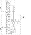
图8所示为本发明分离式串并联混合式双动力驱动系统的分离式实施例方块图之七,其构成为由主动回转动力源100供输出回转动能的转部,耦合联结选择性配置的传动单元129,及选择性配置的离合器102、变速单元109以供驱动第一电机单元101,再由第一电机单元101的转部,经传动单元129将回转动能传输至两个或两个以上的离合器112,及所各别选择性配置的变速单元109,以驱动所各别匹配的负载120以分别构成第一驱动系统1001;Fig. 8 shows the seventh block diagram of the separated embodiment of the separated series-parallel hybrid dual-power drive system of the present invention, which is composed of an active
而由两个或两个以上的第二电机单元103,作为第二驱动系统1002动力源,经选择性各别配置的离合器122、及选择性各别配置的变速单元109以各别驱动所匹配的负载120,而构成两个或两个以上的第二驱动系统1002;And by two or more than two
藉由操控前述第一驱动系统1001及第二驱动系统1002构成分离式串并联混合式双动力驱动系统。By controlling the above-mentioned
此外并可依需要选择性将第一驱动系统1001的主动回转动力源100的回转动能输出端、或所耦合联结的传动单元129输出端、或所耦合联结的离合器102输出回转动能的转部、或所选择性设置的变速单元109输出端、或所驱动第一电机单元101的转部耦合联结于呈多输出的传动单元129的输入端,而传动单元129的各输出端,则供各别经离合器132,以各别耦合联结于作为第二驱动系统1002动力源的两个或两个以上第二电机单元103的转部、或所各别耦合联结的离合器122输出端、或所各别选择性配置的变速单元109输出端、或第二驱动系统1002所各别驱动负载120的输入端,以供操控第一驱动系统1001与第二驱动系统1002之间回转动能的传输状态。In addition, the rotary kinetic energy output end of the active
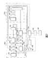
图9所示为本发明分离式串并联混合式双动力驱动系统的分离式实施例方块图之八,其构成为由主动回转动力源100供输出回转动能的转部,耦合联结选择性配置呈多输出轴的传动单元129,其各输出轴供各别耦合联结相对两个或两个以上选择性配置的离合器102及变速单元109,以供驱动两个或两个以上各别配置的第一电机单元101,及两个或两个以上各别配置的离合器112,及分别选择性配置的变速单元109,以供驱动所各别匹配的负载120,以分别构成第一驱动系统1001;Figure 9 shows the eighth block diagram of the separated embodiment of the separated series-parallel hybrid dual-power drive system of the present invention, which is composed of an active
而由两个或两个以上的第二电机单元103,作为第二驱动系统1002动力源,经选择性各别配置的离合器122、及选择性各别配置的变速单元109,以各别驱动所匹配的负载120,而构成两个或两个以上的第二驱动系统1002;And by two or more than two
藉由操控前述第一驱动系统1001及第二驱动系统1002构成分离式串并联混合式双动力驱动系统。By controlling the above-mentioned
此外并可依需要选择性将第一驱动系统1001的主动回转动力源100的回转动能输出端、或所耦合联结呈多输出轴的传动单元129的各别输出端、或所各别耦合联结的离合器102输出回转动能的转部、或所各别选择性设置的变速单元109的各输出端、或所各别驱动第一电机单元101的转部,各别耦合联结于各别离合器132的输入端,而各别离合器132的输出端,则供耦合联结于作为第二驱动系统1002动力源的各别第二电机单元103的转部、或所各别耦合联结的离合器122输出端、或所各别选择性配置的变速单元109输出端、或第二驱动系统1002所各别驱动负载120的输入端,以供操控第一驱动系统1001与第二驱动系统1002之间回转动能的传输状态。In addition, the rotary kinetic energy output end of the active
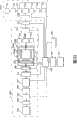
图10所示为本发明分离式串并联混合式双动力驱动系统的分离式实施例方块图之九,其构成为由主动回转动力源100供输出回转动能的转部,耦合联结选择性配置的传动单元129,及选择性配置的离合器102及变速单元109,以供驱动第一电机单元101,再经选择性设置的变速单元109、及经离合器112及可差动的变速单元109,以驱动可差动变速单元109两输出端所匹配的负载120构成第一驱动系统1001;Fig. 10 shows the ninth block diagram of the separated embodiment of the separated series-parallel hybrid dual-power drive system of the present invention, which is composed of an active
而由两个或两个以上的第二电机单元103,作为第二驱动系统1002动力源,经选择性各别配置的变速单元109以各别驱动所匹配的负载120,而构成第二驱动系统1002;Two or more
藉由操控前述第一驱动系统1001及第二驱动系统1002构成分离式串并联混合式双动力驱动系统。By controlling the above-mentioned
此外并可依需要选择性将第一驱动系统1001的主动回转动力源100的回转动能输出端、或所耦合联结的传动单元129输出端、或所耦合联结的离合器102输出回转动能的转部、或选择性设置变速单元109的输出端、或所驱动第一电机单元101的转部,耦合联结于离合器132的输入端,而离合器132的输出端,则供耦合联结于可差动的变速单元109的输入端,而可差动的变速单元109的两输出端,则供各别耦合联结于作为第二驱动系统1002动力源的两个各别设置的第二电机单元103的转部、以供操控第一驱动系统1001与第二驱动系统1002之间回转动能的传输状态。In addition, the rotary kinetic energy output end of the active
图11所示为本发明分离式串并联混合式双动力驱动系统的分离式实施例方块图之十,其构成为由主动回转动力源100供输出回转动能的转部,耦合联结选择性配置的传动单元129,及选择性配置的离合器102及变速单元109,以供驱动第一电机单元101,并由第一电机单元101的转部耦合联结选择性设置的变速单元109及离合器112,以驱动可差动的变速单元109两输出端所匹配的负载120构成第一驱动系统1001;Figure 11 shows the tenth block diagram of the separated embodiment of the separated series-parallel hybrid dual-power drive system of the present invention, which is composed of an active
而由两个或两个以上的第二电机单元103,作为第二驱动系统1002动力源,经选择性配置的变速单元109、离合器122、可差动的变速单元109,以驱动可差动变速单元109的两输出端所匹配的负载120,而构成第二驱动系统1002;And by two or more
藉由操控前述第一驱动系统1001及第二驱动系统1002构成分离式串并联混合式双动力驱动系统。By controlling the above-mentioned
此外并可依需要选择性将第一驱动系统1001的主动回转动力源100的回转动能输出端、或所耦合联结的传动单元129输出端、或所耦合联结的离合器102输出回转动能的转部、或选择性设置变速单元109的输入端、或所驱动第一电机单元101的转部耦合联结于离合器132的输入端,而离合器132的输出端,则供耦合联结于作为第二驱动系统1002动力源的第二电机单元103的转部、或所选择性配置的变速单元109输出端、或所耦合联结的离合器122输出端、或离合器122与所驱动负载120间的可差动的变速单元109输入端,以供操控第一驱动系统1001与第二驱动系统1002之间回转动能的传输状态。In addition, the rotary kinetic energy output end of the active
图12所示为本发明分离式串并联混合式双动力驱动系统的分离式实施例方块图之十一,其构成为由主动回转动力源100供输出回转动能的转部,耦合联结选择性配置的传动单元129,及选择性配置的离合器102及变速单元109,以供驱动第一电机单元101,并由第一电机单元101的转部耦合联结选择性设置的变速单元109及离合器112,再耦合联结于可选择性设置呈多输出端的传动单元129,呈多输出入端的传动单元129供联结于辅助电机单元1010,及供经离合器122以耦合联结选择性设置的变速单元109,驱动所匹配的负载120,构成第一驱动系统1001;Figure 12 shows the eleventh block diagram of the separate embodiment of the separate series-parallel hybrid dual-power drive system of the present invention, which is composed of an active
而由第二电机单元103,作为第二驱动系统1002动力源,经选择性配置的变速单元109,以驱动所匹配的负载120,构成第二驱动系统1002;The
藉由操控前述第一驱动系统1001及第二驱动系统1002构成分离式串并联混合式双动力驱动系统。By controlling the above-mentioned
此外并可依需要选择性将第一驱动系统1001的主动回转动力源100的回转动能输出端、或所耦合联结的传动单元129输出端、或所耦合联结的离合器102输出回转动能的转部、或选择性设置变速单元109输入端、或所驱动第一电机单元101的转部耦合联结于离合器132的输入端,而离合器132的输出端,则供耦合联结于作为第二驱动系统1002动力源的第二电机单元103的转部、或所选择性配置的变速单元109输出端、或第二驱动系统1002所驱动负载120的输入端,以供操控第一驱动系统1001与第二驱动系统1002之间回转动能的传输状态。In addition, the rotary kinetic energy output end of the active
图13所示为本发明分离式串并联混合式双动力驱动系统的分离式实施例方块图之十二,其构成为由主动回转动力源100供输出回转动能的转部,耦合联结选择性配置的传动单元129,及选择性配置的离合器102及变速单元109,以供驱动第一电机单元101,并由第一电机单元101的转部耦合联结选择性设置的变速单元109及离合器112,再耦合联结于可选择性设置呈多输出入端的传动单元129,呈多输出入端的传动单元129供联结于辅助电机单元1010,及供经离合器122以耦合联结具有差动功能的变速单元109,具差动功能的变速单元109的两输出端供驱动所匹配的负载120构成第一驱动单元1001;Figure 13 shows the twelfth block diagram of the separate embodiment of the separate series-parallel hybrid dual-power drive system of the present invention, which is composed of an active
而由两个或两个以上的第二电机单元103,作为第二驱动系统1002动力源,经选择性各别配置的变速单元109,以驱动所各别匹配的负载120,而构成第二驱动系统1002;Two or more
藉由操控前述第一驱动系统1001及第二驱动系统1002构成分离式串并联混合式双动力驱动系统。By controlling the above-mentioned
此外并可依需要选择性将第一驱动系统1001的主动回转动力源100的回转动能输出端、或所耦合联结的传动单元129输出端、或所耦合联结的离合器102输出回转动能的转部、或选择性设置变速单元109输入端、或所驱动第一电机单元101的转部耦合联结于离合器132的输入端,而离合器132的输出端,则供耦合联结于可差动的变速单元109的输入端,而可差动的变速单元109两输出端,则供各别耦合联结于作为第二驱动系统1002动力源的两个各别设置的第二电机单元103的转部,以供操控第一驱动系统1001与第二驱动系统1002之间回转动能的传输状态。In addition, the rotary kinetic energy output end of the active
图14所示为本发明分离式串并联混合式双动力驱动系统的分离式实施例方块图之十三,其构成为将主动回转动力源100的回转动能输出端制成同侧不同轴、或不同侧同轴、或不同侧不同轴的多个输出端的结构,以供选择性配置传动单元129,及选择性配置离合器102以耦合联结第一电机单元101,而构成发电单元2000;Figure 14 shows the thirteenth block diagram of the separate embodiment of the separate series-parallel hybrid dual-power drive system of the present invention, which is constituted by making the rotary kinetic energy output end of the active
以及由主动回转动力源100的回转动能输出端其中之一,用以耦合联结于选择性设置的传动单元129,及选择性设置的离合器112及选择性设置的变速单元109,以驱动所匹配的负载120,而与上述发电单元2000共同构成第一驱动系统1001;And one of the rotary kinetic energy output ends of the active
而由第二电机单元103作为第二驱动系统1002动力源,经选择性配置的离合器122、及选择性配置的变速单元109,以驱动所匹配的负载120,构成第二驱动系统1002;The
藉由操控前述第一驱动系统1001及第二驱动系统1002构成分离式串并联混合式双动力驱动系统。By controlling the above-mentioned
此外并可依需要选择性将第一驱动系统1001的主动回转动力源100的回转动能输出端、或所耦合联结的传动单元129输出端、或所耦合联结的离合器112输出回转动能的转部、或选择性设置的变速单元109输出端、或所驱动负载120的输入端耦合联结于离合器132的输入端,而离合器132的输出端,则供耦合联结于作为第二驱动系统1002动力源的第二电机单元103的转部、或所耦合联结的离合器122输出端、或所选择性配置的变速单元109输出端、或第二驱动系统1002所驱动负载120的输入端,以供操控第一驱动系统1001与第二驱动系统1002之间回转动能的传输状态。In addition, the rotary kinetic energy output end of the active
图15所示为本发明分离式串并联混合式双动力驱动系统的分离式实施例方块图之十四,其构成为将主动回转动力源100的回转动能输出端制成同侧不同轴、或不同侧同轴、或不同侧不同轴的多个输出端的结构,以供选择性配置传动单元129,及选择性配置离合器102以供耦合联结第一电机单元101,而构成发电单元2000;Figure 15 shows the fourteenth block diagram of the separated embodiment of the separated series-parallel hybrid dual-power drive system of the present invention, which is composed of the rotary kinetic energy output end of the active
以及由主动回转动力源100的回转动能输出端其中之一,用以耦合联结于选择性装置的传动单元129,及选择性设置的离合器112及选择性设置的可差动变速单元109,以驱动可差动变速单元109两输出端所匹配的负载120,而与上述发电单元2000共同构成第一驱动系统1001;And one of the rotary kinetic energy output ends of the active
而由两个或两个以上的第二电机单元103,作为第二驱动系统1002动力源,经选择性各别配置的变速单元109,以驱动所各别匹配的负载120,构成第二驱动系统1002;Two or more
或藉操控离合器132作脱离或闭合,以操控第一驱动系统1001与第二驱动系统1002之间回转动能的传输状态,以运作于前述功能1~80的相关功能。Alternatively, the clutch 132 is disengaged or closed to control the transmission state of rotational kinetic energy between the
此外并可依需要选择性将第一驱动系统1001的主动回转动力源100的回转动能输出端、或所耦合联结的传动单元129输出端、或所耦合联结的离合器112输出回转动能的转部、或可差动变速单元109输出端耦合联结于离合器132的输入端,而离合器132的输出端,则供耦合联结设置于第二驱动系统1002的可差动变速单元109的输入端,以分别供驱动两个作为第二驱动系统1002动力源的第二电机单元103的转部,以供操控第一驱动系统1001与第二驱动系统1002之间回转动能的传输状态。In addition, the rotary kinetic energy output end of the active
图16所示为本发明分离式串并联混合式双动力驱动系统的分离式实例方块图之十五,图17为本发明串并联混合式双动力驱动系统的分离式实例方块图之十六,图16及图17的实施例中,为由第一驱动系统1001及第二驱动系统1002所构成,其第一驱动系统1001的结构中,由主动回转动力源100输出回转动能的转部,用以耦合联结选择性设置的传动单元129,及耦合联结游星轮组801的游星轮803,而第一电机单元101的转部供联结于游星轮组801的太阳轮802,第一电机单元101的转部与静部间可藉驱动控制单元104的操控,依需要选择性作为电动机功能运作以输出回转动能、或作发电机功能运作在对外输出电能时产生阻尼,藉其阻尼的作用以使主动回转动力源100的回转动能经外环轮804输出;或藉操控驱动控制单元104使第一电机单元101的静部与转部间呈电磁力锁固的运作,电磁力锁固功能亦可依需要选择性由刹车制动器902所取代,并由第一电机单元101转部耦合于刹车制动器902的转动侧,而刹车制动器902的静止侧为锁固于机体或锁固于第一电机单元101的静部,藉此使第一电机单元101呈锁固而使主动回转动力源100的回转动能经外环轮804输出。Fig. 16 shows the block diagram No. 15 of the separated example of the separated series-parallel hybrid dual-power drive system of the present invention, and Fig. 17 is the sixteenth block diagram of the separated example block diagram of the series-parallel hybrid dual-powered drive system of the present invention. In the embodiment of Fig. 16 and Fig. 17, it is constituted by the
此外为配合系统由主动回转动力源100驱动第一电机单元101作发电机功能运作,必需设置刹车制动器901,并由上述游星轮组801的外环轮804,联结于离合器112的输入端及耦合于刹车制动器901的转动侧,刹车制动器901的静止侧为固锁于机体,离合器112的另一端可如图16所示直接、或经选择性设置的变速单元109对外输出驱动负载120,或如图17所示实施例中,离合器112的另一端可联结于可差动变速单元109的输入端,可差动变速单元109的两可差动输出端供驱动所各别匹配的负载120,而构成第一驱动系统1001;In addition, in order to cooperate with the system to drive the
上述第一驱动系统1001可依需要选择设置或不设置第二电机单元103,若系统的第一驱动系统1001依需要选择设置第二电机单元103时,则于图16实施例中第二电机单元103可为直接或经选择性设置的变速单元109耦合联结于负载120,于图17实施例中,则可耦合联结于离合器112所驱动的可差动的变速单元109的输入端,离合器112及刹车制动器901可为个别装置或一体共构;The above-mentioned
第二驱动系统1002藉由第二电机单元103作为动力源,以耦合联结选择性配置的变速单元109或其它传动装置,以驱动一个或一个以上的负载120,或依需要选择由第二电机单元103的转部联结于可差动变速单元109的输入端,可差动变速单元109的两可差动输出端供驱动所各别匹配的负载120,而藉上述结构构成第二驱动系统1002;The
或藉操控离合器132作脱离或闭合,以操控第一驱动系统1001与第二驱动系统1002之间回转动能的传输状态,以运作于前述功能1~80的相关功能。Alternatively, the clutch 132 is disengaged or closed to control the transmission state of rotational kinetic energy between the
上述图16及图17的实施例主要运转功能含:第一驱动系统1001的运转功能为于刹车制动器901闭合而离合器112脱离时,外环轮804被锁固,而由主动回转动力源100单独经游星轮803驱动太阳轮802带动第一电机单元101作发电机功能运转,以供驱动第一驱动系统1001本身所选择性配置的第二电机单元103,或供驱动第二驱动系统1002所配置的第二电机单元103,或同时驱动第一驱动系统1001及第二驱动系统1002所配置的第二电机单元103,作串联式混合动力的运转输出或对储放电装置106充电功能的运作或两种功能同时运作;The main operating functions of the above-mentioned embodiments of Figure 16 and Figure 17 include: the operating function of the
或由第一电机单元101发电的电能与储放电装置106的电能,共同驱动设置于第一驱动系统1001的第二电机单元103,或共同驱动设置于第二驱动系统1002的第二电机单元103,或共同驱动两驱动系统的第二电机单元103。Or the electric energy generated by the
设置于第一驱动系统1001的第二电机单元103,以及设置于第二驱动系统1002的第二电机单元103,可于离合器112闭合时,藉由储放电装置106的电能与主动回转动力源100的回转动能共同驱动负载120;The
于离合器112脱离而由主动回转动力源100驱动第一电机单元101作发电机功能运转时,第二电机单元103可藉由第一电机单元101所发电的电能,经驱动控制单元104的操控作串联式混合动力的运转;When the clutch 112 is disengaged and the active
或藉由储放电装置106的电能经驱动控制单元104的操控,单独驱动第二电机单元103作电动机功能驱动运转;Or through the control of the
或由第一电机单元101发电的电能与储放电装置106的电能,经驱动控制单元104的操控共同驱动第二电机单元103作电动机功能运转;Or the electric energy generated by the
此外亦可藉由第二电机单元103作刹车制动的再生发电功能运转,将再生发电的电能对储放电装置106充电或对其他电能驱动的负载供电;In addition, the
第一驱动系统1001所选择性配置的第二电机单元103的转部与负载120之间可为直接、或经依需要选择性设置变速单元109或其它传动装置,以驱动一个或一个以上的负载120,或依需要选择由第二电机单元103的转部联结于可差动变速单元109的输入端,而由可差动变速单元109的两可差动输出端供驱动所各别匹配的负载120;藉上述第一驱动系统1001的构成结构及运作以驱动所匹配的负载120。The
此外并可依需要选择性将第一驱动系统1001的主动回转动力源100的回转动能输出端,或所耦合联结的传动单元129输出端耦合联结于离合器132的输入端,而离合器132的输出端,则供耦合联结于图16所示作为第二驱动系统1002动力源的第二电机单元103的转部、或供耦合联结于选择性设置的变速单元109的输出端;或供耦合联结于如图17所示作为第二驱动系统1002动力源的第二电机单元103的转部、或供耦合联结于选择性配置于第二驱动系统1002,供耦合于两个或两个以上负载120的可差动的变速单元109输入端,以供操控第一驱动系统1001与第二驱动系统1002间回转动能的传输状态。In addition, the rotary kinetic energy output end of the active
图18所示为本发明分离式串并联混合式双动力驱动系统的分离式实施例方块图之十七,为由第一驱动系统1001及第二驱动系统1002所构成,其第一驱动系统1001的结构中,由主动回转动力源100输出回转动能的转部,用以耦合联结选择性设置的传动单元129,及耦合联结游星轮组801的游星轮803,而第一电机单元101的转部供联结于游星轮组801的太阳轮802,第一电机单元101的转部与静部间可藉驱动控制单元104的操控,依需要选择性作为电动机功能运作以输出回转动能、或作发电机功能运作在对外输出电能时产生阻尼,藉其阻尼的作用以使主动回转动力源100的回转动能经外环轮804输出;或藉操控驱动控制单元104使第一电机单元101的静部与转部间呈电磁力锁固的运作,电磁力锁固功能亦可依需要选择性由刹车制动器902所取代,并由第一电机单元101转部耦合于刹车制动器902的转动侧,而刹车制动器902的静止侧为锁固于机体或锁固于第一电机单元101的静部,藉此使第一电机单元101呈锁固而使主动回转动力源100的回转动能经外环轮804输出。Figure 18 shows the seventeenth block diagram of the separate embodiment of the separate series-parallel hybrid dual-power drive system of the present invention, which is composed of a
此外为配合系统由主动回转动力源100驱动第一电机单元101作发电机功能运作,必需设置刹车制动器901,并由上述游星轮组801的外环轮804联结于离合器112的输入端及耦合于刹车制动器901的转动侧,刹车制动器901的静止侧为固锁于机体,离合器112的另一端可直接、或经选择性设置的变速单元109对外输出驱动负载120;In addition, in order to cooperate with the system to drive the
上述第一驱动系统1001为可依需要选择设置或不设置第二电机单元103,若系统的第一驱动系统1001依需要选择设置第二电机单元103,则第二电机单元103可为直接或经选择性设置的变速单元109耦合联结于负载120,或耦合联结于离合器112所驱动的可差动的变速单元109的输入端,离合器112及刹车制动器901可为个别装置或一体共构;The above-mentioned
第二驱动系统1002藉由两个或两个以上第二电机单元103作为动力源,以个别耦合联结选择性配置的可差动的变速单元109或其它传动装置,以驱动各别所耦合的负载120,而藉上述结构构成第二驱动单元1002;The
或藉操控离合器132作脱离或闭合,以操控第一驱动系统1001与第二驱动系统1002之间回转动能的传输状态,以运作于前述功能1~80的相关功能。Alternatively, the clutch 132 is disengaged or closed to control the transmission state of rotational kinetic energy between the
上述图18的实施例主要运转功能含:第一驱动系统1001的运转功能为于刹车制动器901闭合而离合器112脱离时,外环轮804被锁固,而由主动回转动力源100单独经游星轮803驱动太阳轮802带动第一电机单元101作发电机功能运转,以供驱动第一驱动系统1001本身所选择性配置的第二电机单元103,或供驱动第二驱动系统1002所配置的第二电机单元103,或同时驱动第一驱动系统1001及第二驱动系统1002所配置的第二电机单元103,作串联式混合动力的运转输出或对储放电装置106充电功能的运作或两种功能同时运作;The main operating functions of the above-mentioned embodiment of FIG. 18 include: the operating function of the
或由第一电机单元101发电的电能与储放电装置106的电能,共同驱动设置于第一驱动系统1001的第二电机单元103,或共同驱动设置于第二驱动系统1002的第二电机单元103,或共同驱动两驱动单元的第二电机单元103。Or the electric energy generated by the
设置于第一驱动系统1001的第二电机单元103,以及设置于第二驱动系统1002的第二电机单元103,可于离合器112闭合时,藉由储放电装置106的电能与主动回转动力源100的回转动能共同驱动负载120;The
于离合器112脱离,刹车制动器901呈闭合状态而刹车制动器902呈脱离状态,此时由主动回转动力源100经游星轮组801驱动第一电机单元101作发电机功能运转时,第二电机单元103可藉由第一电机单元101所发电的电能作串联式混合动力的运转,或藉由储放电装置106的电能经驱动控制单元104的操控单独作电动机功能驱动运转,或由第一电机单元101发电的电能与储放电装置106的电能,经驱动控制单元104的操控共同驱动第二电机单元103作电动机功能运转;When the clutch 112 is disengaged, the
此外亦可藉由第二电机单元103作刹车制动的再生发电功能运转,将再生发电的电能对储放电装置106充电或对其他电能驱动的负载供电;In addition, the
第一驱动系统1001所选择性配置的第二电机单元103的转部与负载120之间可为直接、或经依需要选择性设置变速单元109或其它传动装置,以驱动一个或一个以上的负载120,或依需要选择由第二电机单元103的转部联结于可差动变速单元109的输入端,而由可差动变速单元109的两可差动输出端供驱动所各别匹配的负载120;藉上述第一驱动系统1001的构成结构及运作以驱动所匹配的负载120。The
此外并可依需要选择性将第一驱动系统1001的主动回转动力源100的回转动能输出端,或所耦合联结的传动单元129输出端耦合联结于离合器132的输入端,而离合器132的输出端,则供耦合联结于选择性配置于第二驱动系统1002,供耦合于两个或两个以上第二电机单元103的可差动的变速单元109输入端,以供操控第一驱动系统1001与第二驱动系统1002之间回转动能的传输状态。In addition, the rotary kinetic energy output end of the active
图19所示为本发明分离式串并联混合式双动力驱动系统的分离式实施例方块图之十八,图19实施例中,其第一驱动系统1001及第二驱动系统1002的结构与图16相同,而图20所示为本发明串并联混合式双动力驱动系统的分离式实施例方块图之十九,图20的实施例中,其第一驱动系统1001及第二驱动系统1002的结构与图17相同,唯其不同在离合器132的输入端,耦合联结于第一驱动系统1001所配置的第二电机单元103的转部,或第二电机单元103所配置的变速单元109的输入端或输出端,而离合器132的输出端,则为耦合联结于作为第二驱动系统1002动力源的第二电机单元103的转部,或耦合联结于第二电机单元103转部所选择性配置变速单元109或可差动的变速单元109输入端,上述离合器132可依需要选择性设置,以供操控第一驱动系统1001与第二驱动系统1002间回转动能的传输状态,而主动回转动力源100输出端为可依需要选择性设置变速单元109再驱动游星轮组801的游星轮803。Figure 19 shows the eighteenth block diagram of the separate embodiment of the separate series-parallel hybrid dual-power drive system of the present invention. In the embodiment of Figure 19, the structure and diagram of the
图21所示为本发明分离式串并联混合式双动力驱动系统的分离式实施例方块图之二十,图21的实施例中,其第一驱动系统1001及第二驱动系统1002的结构与图18相同,唯其不同在于离合器132的输入端,耦合联结于第一驱动系统1001所配置的第二电机单元103的转部,或第二电机单元103所配置的变速单元109的输入端或输出端,而离合器132的输出端,为耦合联结选择性设置于第二驱动系统1002的可差动变速单元109的输入端,而可差动的变速单元109的两输出端,为供分别耦合联结于作为第二驱动系统1002动力源的两个或两个以上第二电机单元103的转部,上述离合器132可依需要选择性设置,以供操控第一驱动系统1001与第二驱动系统1002间回转动能的传输状态,而主动回转动力源100输出端为可依需要选择性设置变速单元109再驱动游星轮组801的游星轮803;Figure 21 shows the twentieth block diagram of the separate embodiment of the separate series-parallel hybrid dual-power drive system of the present invention. In the embodiment of Figure 21, the structures of the
前述图16、17、18、19、20、21所述系统中第一驱动系统1001所配置游星轮组的差动功能,亦可由同功能原理而不同结构形态的周转轮组1030取代构成。16, 17, 18, 19, 20, 21, the differential function of the planetary wheel set configured in the
如图22为本发明以差动轮组取代图16游星轮组的分离式实施例方块图之二十一,图23为本发明以差动轮组取代图17游星轮组的分离式实施例方块图之二十二,图22及图23的实施例中为由周转轮组1030取代游星轮组801,周转轮组1030的三个输出入端中,第一输出入端501为供联结第一输出入轮组511,以及联结主动回转动力源100回转动能输出端,或联结于选择性设置的传动单元129,传动单元129为由主动回转动力源100所驱动,第二输出入端502为供联结第一电机单元101及刹车制动器902及第二输出入轮组512,第一输出入轮组511及第二输出入轮组512供耦合于差动轮组5130,以供经旋臂5131牵动差动输出轮组5132及第三输出入轮组513,以由第三输出入轮组513驱动第三输出入端503及所联结刹车制动器901的转部及离合器112,离合器112的另一端可如图22所示直接或经选择性设置的变速单元109驱动负载120,或如图23所示实施例中,由离合器112的另一端可联结于可差动变速单元109的输入端,可差动变速单元109的两可差动输出端供驱动所各别匹配的负载120,而构成第一驱动系统1001;Figure 22 is the 21st block diagram of the separate embodiment of the present invention replacing the planetary wheel set in Figure 16 with a differential wheel set, and Figure 23 is the separated embodiment of the present invention replacing the planetary wheel set in Figure 17 with a differential wheel set The twenty-second block diagram of the embodiment, in the embodiment of Fig. 22 and Fig. 23, the planetary wheel set 801 is replaced by the epicyclic wheel set 1030, and among the three input and output ends of the epicyclic wheel set 1030, the first input and output end 501 is For connecting the first output and output wheel set 511, and connecting the rotary kinetic energy output end of the active rotary power source 100, or connecting to the selectively provided transmission unit 129, the transmission unit 129 is driven by the active rotary power source 100, and the second output The input end 502 is for connecting the first motor unit 101 and the brake 902 and the second input-output wheel set 512, and the first input-output wheel set 511 and the second input-output wheel set 512 are coupled to the differential wheel set 5130 for The differential output wheel set 5132 and the third input and output wheel set 513 are driven by the swing arm 5131, so that the third input and output end 503 and the rotating part of the connected brake 901 and the clutch 112 are driven by the third input and output wheel set 513. The other end of the clutch 112 can drive the
上述第一驱动系统1001可依需要选择是否设置第二电机单元103,若选择设置第二电机单元103,则于图22实施例中第二电机单元103可为直接或经选择性设置的变速单元109耦合联结于负载120,于图23实施例中,则可耦合联结于离合器112所驱动的可差动的变速单元109的输入端;The above-mentioned
第二驱动系统1002藉由第二电机单元103作为第二驱动系统1002动力源,以耦合联结选择性配置的变速单元109或其它传动装置,以驱动一个或一个以上的负载120,或依需要选择由第二电机单元103的转部联结于可差动变速单元109的输入端,可差动变速单元109的两可差动输出端供驱动所各别匹配的负载120;而藉上述结构构成第二驱动系统1002;The
或藉操控离合器132作脱离或闭合,以操控第一驱动系统1001与第二驱动系统1002之间回转动能的传输状态,以运作于前述功能1~80的相关功能。Alternatively, the clutch 132 is disengaged or closed to control the transmission state of rotational kinetic energy between the
上述图22及图23实施例主要运转功能含:当离合器112脱离,刹车制动器901呈闭合而刹车制动器902呈脱离状态,此时由主动回转动力源100经周转轮组1030驱动第一电机单元101作发电机功能运转,其发电的电能藉驱动控制单元104的操控,供驱动设置于第一驱动系统1001的第二电机单元103,或供驱动设置于第二驱动系统1002的第二电机单元103,或同时驱动两者作电动机功能运转以驱动负载,构成串联式混合动力功能的运作;The main operating functions of the above-mentioned embodiments in Figure 22 and Figure 23 include: when the clutch 112 is disengaged, the
或于系统设有储放电装置106时,前述第二电机单元103接受第一电机单元101及储放电装置106的电能,经驱动控制单元104的操控驱动作电动机功能运转以驱动负载120;Or when the system is equipped with a storage and
或由前述第二电机单元103接受储放电装置106的电能经驱动控制单元104的操控驱动作电动机功能运转以驱动负载120;Or the aforementioned
或于刹车制动器901呈脱离而刹车制动器902呈闭合、离合器112呈闭合状态时,由前述第二电机单元103接受储放电装置106的电能经驱动控制单元104的操控驱动作电动机功能运转以和主动回转动力源100的回转动能共同驱动负载120;Or when the
或于刹车制动器901呈脱离而刹车制动器902呈闭合、离合器112呈闭合状态时,由主动回转动力源100的回转动能驱动负载120;Or when the
或由前述第二电机单元103作动能回收的再生发电以对储放电装置106充电或对其他电能驱动的负载130供电;Or the aforementioned
此外并可依需要选择性将第一驱动系统1001的主动回转动力源100的回转动能输出端,或所耦合联结的传动单元129输出端耦合联结于离合器132的输入端,而离合器132的输出端,则供耦合联结于图22所示作为第二驱动系统1002动力源的第二电机单元103的转部、或供耦合联结于选择性设置的变速单元109的输出端;或供耦合联结于如图23所示作为第二驱动系统1002动力源的第二电机单元103的转部、或供耦合联结于选择性配置于第二驱动系统1002,供耦合于两个或两个以上负载120的可差动的变速单元109输入端,以供操控第一驱动系统1001与第二驱动系统1002之间回转动能的传输状态。In addition, the rotary kinetic energy output end of the active
如图24为本发明以差动轮组取代图18游星轮组的分离式实施例方块图之二十三,图24中为由周转轮组1030以取代游星轮组801,周转轮组1030的三个输出入端中,第一输出入端501为供联结第一输出入轮组511,以及联结主动回转动力源100输出回转动能的转部,或联结于选择性设置的传动单元129,传动单元129为由主动回转动力源100所驱动,第二输出入端502为供联结第一电机单元101及刹车制动器902及第二输出入轮组512,第一输出入轮组511及第二输出入轮组512供耦合于差动轮组5130,以供经旋臂5131牵动差动输出轮组5132及第三输出入轮组513,以由第三输出入轮组513驱动第三输出入端503及所联结刹车制动器901及离合器112,离合器112的另一端联结于可差动变速单元109的输入端,可差动变速单元109的两可差动输出端供驱动所各别匹配的负载120,进而构成第一驱动系统1001;第一驱动系统1001可依需要选择是否设置第二电机单元103,若选择设置第二电机单元103,则第二电机单元103可耦合联结于离合器112或耦合联结于离合器112所驱动的可差动的变速单元109输入端;Figure 24 is the 23rd block diagram of the separated embodiment of the present invention replacing the planetary wheel set in Figure 18 with a differential wheel set. In Figure 24, the
第二驱动系统1002藉由两个或两个以上的第二电机单元103作为动力源,以个别耦合联结选择性配置的变速单元109或其它传动装置,以驱动各别所耦合的负载120,而藉上述结构构成第二驱动系统1002;The
或藉操控离合器132作脱离或闭合,以操控第一驱动系统1001与第二驱动系统1002之间回转动能的传输状态,以运作于前述功能1~80的相关功能。Alternatively, the clutch 132 is disengaged or closed to control the transmission state of rotational kinetic energy between the
上述图24的实施例主要运转功能含:当离合器112脱离,刹车制动器901呈闭合而刹车制动器902呈脱离状态,此时由主动回转动力源100经周转轮组1030驱动第一电机单元101作发电机功能运转,而由设置于第一驱动系统1001的第二电机单元103,或与设置于第二驱动系统1002的第二电机单元103,共同或由其中的一接受第一电机单元101发电电能经驱动控制单元104的操控以作电动机功能运转驱动负载驱动构成串联式混合动力功能的运作;The main operating functions of the above-mentioned embodiment in FIG. 24 include: when the clutch 112 is disengaged, the
或于系统设有储放电装置106时,前述第二电机单元103接受第一电机单元101及储放电装置106的电能,经驱动控制单元104的操控驱动作电动机功能运转以驱动负载120;或由前述第二电机单元103接受储放电装置106的电能经驱动控制单元104的操控驱动作电动机功能运转以驱动负载120;Or when the system is equipped with a storage and
或于刹车制动器901呈脱离而刹车制动器902呈闭合、离合器112呈闭合状态时,由前述第二电机单元103接受储放电装置106的电能经驱动控制单元104的操控驱动作电动机功能运转以和主动回转动力源100的回转动能共同驱动负载120;Or when the
或于刹车制动器901呈脱离而刹车制动器902呈闭合、离合器112呈闭合状态时,由主动回转动力源100的回转动能驱动负载120;Or when the
或由前述第二电机单元103作动能回收的再生发电以对储放电装置106充电或对其他电能驱动的负载130供电;Or the aforementioned
此外并可依需要选择性将第一驱动系统1001的主动回转动力源100的回转动能输出端,或所耦合联结的传动单元129输出端耦合联结于离合器132的输入端,而离合器132的输出端,则供耦合联结于选择性配置于第二驱动系统1002,供耦合于两个或两个以上第二电机单元103的可差动的变速单元109输入端,以供操控第一驱动系统1001与第二驱动系统1002之间回转动能的传输状态。In addition, the rotary kinetic energy output end of the active
图25所示为本发明以差动轮组取代图19游星轮组的分离式实施例方块图之二十四,图25实施例中,其第一驱动系统1001及第二驱动系统1002的结构与图22相同,而图26所示为本发明以差动轮组取代图20游星轮组的分离式实施例方块图之二十五,图25实施例中,其第一驱动系统1001及第二驱动系统1002的结构与图23相同,唯其不同在于离合器132的输入端,耦合联结于第一驱动系统1001所配置的第二电机单元103或的转部、或耦合联结于第二电机单元103所配置的变速单元109的输入端或输出端,而离合器132的输出端,则为耦合联结于作为第二驱动系统1002动力源的第二电机单元103的转部,或耦合联结于第二电机单元103转部所选择性配置的变速单元109、或可差动的变速单元109的输入端,上述离合器132可依需要选择性设置,以供操控第一驱动系统1001与第二驱动系统1002间回转动能的传输状态,而主动回转动力源100输出端为可依需要选择性设置变速单元109再驱动游星轮组801的游星轮803。Figure 25 shows the twenty-fourth block diagram of the separated embodiment of the present invention replacing the planetary wheel set in Figure 19 with a differential wheel set. In the embodiment of Figure 25, the
图27所示为本发明以差动轮组取代图21游星轮组的分离式实施例方块图之二十六,图27的实施例中,其第一驱动系统1001及第二驱动系统1002的结构与图24相同,唯其不同在于离合器132的输入端,耦合联结于第一驱动系统1001所配置的第二电机单元103的转部、或耦合联结于第二电机单元103所配置的变速单元109的输入端或输出端,而离合器132的输出端,为耦合联结选择性设置于第二驱动系统1002的可差动的变速单元109的输入端,而可差动的变速单元109的两输出端,为供分别耦合联结于作为第二驱动系统1002动力源的两个或两个以上第二电机单元103的转部,上述离合器132可依需要选择性设置,以供操控第一驱动系统1001与第二驱动系统1002间回转动能的传输状态,而主动回转动力源100输出端为可依需要选择性设置变速单元109,再驱动游星轮组801的游星轮803。Figure 27 shows the twenty-sixth block diagram of the separated embodiment of the present invention that replaces the planetary wheel set in Figure 21 with a differential wheel set. In the embodiment of Figure 27, its
前述图16、17、18、19、20、21所述系统中第一驱动单元1001所配置游星轮组的差动功能亦可由同功能不同结构型态的双动型电机单元所取代构成。16, 17, 18, 19, 20, 21 in the system described above, the differential function of the planetary gear set configured by the
图28所示为本发明以双动型电机单元取代图16游星轮组的分离式实施例方块图之二十七,图29为本发明以双动型电机单元取代图16游星轮组的分离式实施例方块图之二十八,图28及图29的实施例中,为由主动回转动力源100输出回转动能的转部,供耦合联结传动单元129、及耦合联结选择性配置的离合器102及变速单元109,以驱动第一电机单元101的转部;第一驱动系统1001并设有双动型电机单元1040,双动型电机单元1040为由交流或直流、无刷或有刷、同步或异步的双动型电机结构所构成,可为呈圆筒状或盘状或锥状结构,其构成包括第一转部1041及第二转部1042,第一转部1041与第二转部1042之间设有可操控离合器122,第一转部1041供与刹车制动器901的转部联结,再经离合器112与第一电机单元101的转部联结,刹车制动器901的静止侧为固锁于机体,双动型电机单元1040的第二转部1042,则可如图28实施例所示直接或经选择性设置的变速单元109以驱动负载120,或如图29所示由双动型电机单元1040的第二转部1042联结于可差动变速单元109的输入端,可差动变速单元109的两可差动输出端供驱动所各别匹配的负载120,而构成第一驱动系统1001;Figure 28 shows the twenty-seventh block diagram of the separated embodiment of the present invention replacing the planetary wheel set in Figure 16 with a double-acting motor unit, and Figure 29 shows that the present invention replaces the planetary wheel set in Figure 16 with a double-acting motor unit The twenty-eighth of the block diagram of the separate embodiment, in the embodiment of Fig. 28 and Fig. 29, is the rotary part that outputs the rotary kinetic energy from the active
第一驱动系统1001可依需要选择是否设置第二电机单元103,若选择设置第二电机单元103,则于图28实施例中第二电机单元103的转部,可为直接或经选择性设置的变速单元109耦合联结于负载120,于图29实施例中,则第二电机单元103的转部可耦合联结于第二转部1042所驱动的可差动的变速单元109;The
第二驱动系统1002藉由第二电机单元103作为动力源,以耦合联结选择性配置的变速单元109或其它传动装置,以驱动一个或一个以上的负载120,或依需要选择由第二电机单元103的转部联结于可差动变速单元109的输入端,可差动变速单元109的两可差动输出端供驱动所各别匹配的负载120,而藉上述结构构成第二驱动系统1002;The
或藉操控离合器132作脱离或闭合,以操控第一驱动系统1001与第二驱动系统1002之间回转动能的传输状态,以运作于前述功能1~80的相关功能。Alternatively, the clutch 132 is disengaged or closed to control the transmission state of rotational kinetic energy between the
上述图28、29实施例主要运转功能含:当离合器112脱离,刹车制动器901呈闭合而离合器122呈脱离状态,此时由主动回转动力源100驱动第一电机单元101作发电机功能运转,由设置于第一驱动系统1001的第二电机单元103,或与设置于第二驱动系统1002的第二电机单元103,共同或由其中的一接受第一电机单元101发电电能经驱动控制单元104的操控以作电动机功能运转驱动负载驱动构成串联式混合动力功能的运作;The main operating functions of the above-mentioned embodiments in Figures 28 and 29 include: when the clutch 112 is disengaged, the
或于系统设有储放电装置106时,前述第二电机单元103接受第一电机单元101及储放电装置106的电能,经驱动控制单元104的操控驱动作电动机功能运转以驱动负载120;Or when the system is equipped with a storage and
或由前述第二电机单元103接受储放电装置106的电能经驱动控制单元104的操控驱动作电动机功能运转以驱动负载120;Or the aforementioned
或于离合器102、112呈闭合而离合器122及刹车制动器901呈脱离状态时,由前述第二电机单元103接受储放电装置106的电能经驱动控制单元104的操控驱动作电动机功能运转以和主动回转动力源100的回转动能共同驱动负载120;Or when the
或由前述第二电机单元103作动能回收的再生发电以对储放电装置106充电或对其他电能驱动的负载130供电;Or the aforementioned
或于离合器102、112、122呈闭合而刹车制动器901脱离状态时,由主动回转动力源100的回转动能驱动负载120;Or when the
此外并可依需要选择性将第一驱动系统1001的主动回转动力源100的回转动能输出端,或所耦合联结的传动单元129输出端耦合联结于离合器132的输入端,而离合器132的输出端,则供耦合联结于图28所示作为第二驱动系统1002动力源的第二电机单元103的转部、或供耦合联结于选择性设置的变速单元109的输出端;或供耦合联结于如图29所示作为第二驱动系统1002动力源的第二电机单元103的转部、或供耦合联结于选择性配置于第二驱动系统1002,供耦合于两个或两个以上负载120的可差动的变速单元109输入端,以供操控第一驱动系统1001与第二驱动系统1002之间回转动能的传输状态。In addition, the rotary kinetic energy output end of the active
图30所示为本发明以双动型电机单元取代图18游星轮组的分离式实施例方块图之二十九,图30的实施例中,为由主动回转动力源100输出回转动能的转部,供耦合联结传动单元129、及耦合联结选择性配置的离合器102及变速单元109,以驱动第一电机单元101的转部;第一驱动系统1001并设有双动型电机单元1040,双动型电机单元1040为由交流或直流、无刷或有刷、同步或异步的双动型电机结构所构成,可为呈圆筒状或盘状或锥状结构,其构成包括第一转部1041及第二转部1042,第一转部1041与第二转部1042之间设有可操控离合器122,第一转部1041供与刹车制动器901的转部联结,再经离合器112与第一电机单元101的转部联结,刹车制动器901的静止侧为固锁于机体,双动型电机单元1040的第二转部1042则耦合联结于可差动变速单元109的输入端,可差动变速单元109的两可差动输出端供驱动所各别匹配的负载120,而构成第一驱动系统1001;Figure 30 shows the twenty-ninth block diagram of the separated embodiment of the present invention that replaces the planetary wheel set in Figure 18 with a double-acting motor unit. In the embodiment of Figure 30, the rotary kinetic energy is output by the active
第一驱动系统1001可依需要选择是否设置第二电机单元103,若选择设置第二电机单元103,则第二电机单元103可耦合联结于第二转部1042或耦合联结于第二转部1042所驱动的可差动的变速单元109输入端;The
第二驱动系统1002藉由两个或两个以上的第二电机单元103作为动力源,以个别耦合联结选择性配置的变速单元109或其它传动装置,以驱动各别所耦合的负载120,而藉上述结构,构成第二驱动系统1002;The
或藉操控离合器132作脱离或闭合,以操控第一驱动系统1001与第二驱动系统1002之间回转动能的传输状态,以运作于前述功能1~80的相关功能。Alternatively, the clutch 132 is disengaged or closed to control the transmission state of rotational kinetic energy between the
上述图30的实施例主要运转功能含:当离合器112脱离,刹车制动器901呈闭合而离合器122呈脱离状态,此时而由主动回转动力源100驱动第一电机单元101作发电机功能运转,由设置于第一驱动系统1001的第二电机单元103,或与设置于第二驱动系统1002的第二电机单元103,共同或由其中的一接受第一电机单元101发电电能经驱动控制单元104的操控以作电动机功能运转驱动负载驱动构成串联式混合动力功能的运作;The main operating functions of the above-mentioned embodiment of FIG. 30 include: when the clutch 112 is disengaged, the
或于系统设有储放电装置106时,前述第二电机单元103接受第一电机单元101及储放电装置106的电能,经驱动控制单元104的操控驱动作电动机功能运转以驱动负载120;Or when the system is equipped with a storage and
或于离合器102、112呈闭合而离合器122及刹车制动器901呈脱离状态时,由前述第二电机单元103接受储放电装置106的电能经驱动控制单元104的操控驱动作电动机功能运转以驱动负载120;Or when the
或由前述第二电机单元103接受储放电装置106的电能经驱动控制单元104的操控驱动作电动机功能运转以和主动回转动力源100的回转动能共同驱动负载120;Or the aforementioned
或由前述第二电机单元103作动能回收的再生发电以对储放电装置106充电或对其他电能驱动的负载130供电;Or the aforementioned
或于离合器102、112、122呈闭合而刹车制动器901脱离状态时,由主动回转动力源100的回转动能驱动负载120;Or when the
此外并可依需要选择性将第一驱动系统1001的主动回转动力源100的回转动能输出端,或所耦合联结的传动单元129输出端耦合联结于离合器132的输入端,而离合器132的输出端,则供耦合联结于选择性配置于第二驱动系统1002,供耦合于两个或两个以上第二电机单元103的可差动的变速单元109输入端,以供操控第一驱动系统1001与第二驱动系统1002之间回转动能的传输状态。In addition, the rotary kinetic energy output end of the active
图31所示为本发明以双动型电机单元取代图19游星轮组的分离式实施例方块图之三十,图31的实施例中,其第一驱动系统1001及第二驱动系统1002的结构与图28相同,而图32所示为本发明以双动型电机单元取代图20游星轮组的分离式实施例方块图之三十一,图32的实施例中,其第一驱动系统1001及第二驱动系统1002的结构与图29相同,此项系统的主动回转动力源100输出端亦可依需要选择性设置变速单元109,再驱动游星轮组801的游星轮803,并可依需要选择性设置离合器132,以供操控第一驱动系统1001与第二驱动系统1002间回转动能的传输状态,唯其不同在离合器132的输入端,为耦合联结于第一驱动系统1001所选择性配置的第二电机单元103的转部,或耦合联结于第二电机单元103所配置的变速单元109的输入端或输出端,而离合器132的输出端,则为耦合联结于作为第二驱动系统1002动力源的第二电机单元103的转部,或耦合联结设置于第二驱动系统1002的第二电机单元103转部所选择性配置变速单元109,或耦合联结于可差动的变速单元109的输入端。Figure 31 shows the thirtieth block diagram of the separate embodiment of the present invention replacing the planetary wheel set in Figure 19 with a double-acting motor unit. In the embodiment of Figure 31, its
图33所示为本发明以双动型电机单元取代图21游星轮组的分离式实施例方块图之三十二,图33的实施例中,其第一驱动系统1001及第二驱动系统1002的结构与图30相同,此项系统的主动回转动力源100输出端亦可依需要选择性设置变速单元109,再驱动游星轮组801的游星轮803,并可依需要选择性设置离合器132,以供操控第一驱动系统1001与第二驱动系统1002间回转动能的传输状态;唯其不同在于离合器132的输入端,为耦合联结于第一驱动系统1001所配置的第二电机单元103的转部,或耦合联结于第二电机单元103所配置的变速单元109的输入端或输出端,而第二电机单元103的输出端,为耦合联结选择性设置于第二驱动系统1002的可差动的变速单元109的输入端,而可差动的变速单元109的两输出端,为供分别耦合联结于作为第二驱动系统1002动力源的两个或两个以上第二电机单元103的转部。Figure 33 shows the block diagram No. 32 of the separated embodiment of the present invention, which replaces the planetary wheel set in Figure 21 with a double-acting motor unit. In the embodiment of Figure 33, its
此项分离式串并联混合式双动力驱动系统的主动回转动力源100,亦可将主动回转动力源100输出端,先供耦合联结离合器1020,离合器1020为藉人力、或机力、或离心力、或气压、或油压的流力、或电磁力等所操控的离合器、或单向离合器(single way clutch)、或可调控的扭力耦合器或其它用以供传输或切断机械回转动能的传输装置所构成;上述离合器1020为联结耦合于传动单元129与作为前置驱动单元1000的变速单元109及负载120之间,以操控对外输出回转动能的前置驱动单元1000驱动所属负载120,以及藉主动回转动力源100所驱动的第一电机单元101发电的电能,直接或经驱动控制单元104的操控,以驱动第二驱动系统1002的第二电机单元103,构成串联式混合动力驱动功能;或藉操控系统作并联式混合动力驱动等主要功能的运转,及其它如前述功能1~80的相关功能的运转;The active
图34所示为本发明主动回转动力源输出端设有前置驱动单元的系统方块示意图之一,图35为本发明主动回转动力源输出端设有前置驱动单元的系统方块示意图之二,图34及图35所示实施例中其主要构成含:Figure 34 shows one of the system block diagrams in which the output end of the active rotary power source of the present invention is provided with a front drive unit, and Figure 35 is the second block diagram of the system in which the output end of the active rotary power source is provided with a front drive unit in the present invention, Its main composition contains in the embodiment shown in Figure 34 and Figure 35:
——主动回转动力源100的输出端,为先供耦合联结传动单元129、辅助离合器1020,及依需要选择性设置的公知变速单元109,以驱动所属的负载120构成前置驱动单元1000;——The output end of the active
上述离合器1020,为供操控主动回转动力源100,与前置驱动单元1000所负载120之间回转动能的传输状态;The above-mentioned clutch 1020 is used to control the transmission state of rotary kinetic energy between the active
若主动回转动力源100为多轴输出,则前置驱动单元1000亦可选择设置于主动回转动力源100的其它输出端;If the active
另于主动回转动力源100的相同输出端或不同输出端,依需要选择性设置离合器102及变速单元109,以供驱动第一电机单元101,而和前置驱动单元1000共同构成第一驱动系统1001;In addition, at the same output end or different output ends of the active
第二驱动系统1002藉由第二电机单元103作为动力源,而耦合联结选择性设置的公知变速单元109,以驱动变速单元109所匹配的一个或一个以上的负载120,而构成第二驱动系统1002。The
前述前置驱动单元1000的离合器1020的输入端,为耦合联结于由主动回转动力源100所驱动的传动单元129的输出端、或耦合联结于主动回转动力源100的另一输出端,离合器1020与负载120之间所耦合联结的变速单元109,可如图34所示,依需要选择为由具可操控多段或无段变速、倒档、或具有空档功能的变速单元109所构成,以供驱动所属的负载120,或更进一步如图35所示,藉由可操控多段或无段变速、倒档、或具有空档功能,并具有两轴或两轴以上可差动运转输出的变速单元109所构成,以供驱动其各差动输出端所分别配置的负载120作可差动运转。The input end of the clutch 1020 of the aforementioned
第二驱动系统1002藉由第二电机单元103作为动力源,而耦合联结选择性设置的公知变速单元109,以驱动所配置的负载120构成第二驱动系统1002;The
第二驱动系统1002中,由第二电机单元103所驱动的变速单元109,亦可如图34所示,依需要选择为由具有可操控作多段或无段变速、倒档、或空档功能的变速单元109所构成,以供驱动所属的负载120,或更进一步如图35所示,由具有两轴或两轴以上可作可差动运转输出端的可差动的变速单元109所构成,以供驱动其个别差动输出端所分别配置的负载120作差动运转。In the
前述主动回转动力源100输出端经传动单元129所耦合联结的离合器102、及选择性设置的变速单元109、及第一电机单元101,除可依需要为结合于第一驱动系统1001外,亦可依需要而为结合于第二驱动系统1002或独立设置。The clutch 102 coupled to the output end of the aforementioned active
图34及图35所示系统中,主动回转动力源100除供驱动前置驱动单元1000外,其运作包括可藉主动回转动力源100驱动第一电机单元101以作发电机功能运转,其发电的电能供驱动设置于第二驱动系统1002的第二电机单元103,以产生回转动能驱动负载120,使系统作串联式混合动力系统功能的运作;In the system shown in Fig. 34 and Fig. 35, in addition to driving the
或于系统设有储放电装置106时,由主动回转动力源100驱动第一电机单元101作发电机功能运转,其发电的电能供对储放电装置106充电,或对其他电能驱动的负载130(含外接不特定负载)供电,以及供驱动第二驱动系统1002的第二电机单元103,以产生回转动能驱动负载120;Or when the system is equipped with a storage and
或于系统设有储放电装置106时,由主动回转动力源100驱动第一电机单元101作发电机功能运转,其所发电的电能,供对储放电装置106充电,或对其他以电能驱动的负载130(含外接不特定负载)供电;Or when the system is equipped with a storage and
或由第一电机单元101作发电机功能运转,其发电的电能与储放电装置106的电能,共同驱动第二电机单元103以产生回转动能驱动负载120,或对其他以电能驱动的负载130(含外接不特定负载)供电;Or the
或由储放电装置106的电能,单独驱动设置于第二驱动系统1002的第二电机单元103以产生回转动能驱动负载;Or use the electric energy of the storage and
或由储放电装置106的电能,驱动第二驱动系统1002的第二电机单元103产生的回转动能,与主动回转动力源100的回转动能,共同驱动负载;Or the electric energy of the storage and
或藉第一电机单元101、或第二电机单元103,于刹车制动产生的再生发电的电能,对储放电装置106充电,或对其他电能驱动的负载130(含外接不特定负载)供电。Or use the regenerative power generated by the
图36所示为本发明主动回转动力源输出端设有前置驱动单元的系统方块示意图之三,图36所示实施例的主要构成含:Figure 36 shows the third schematic block diagram of the system in which the output end of the active rotary power source of the present invention is provided with a pre-drive unit. The main components of the embodiment shown in Figure 36 include:
——主动回转动力源100的输出端,为先供耦合联结传动单元129、辅助离合器1020,及依需要选择性设置的公知变速单元109,以驱动所属的负载120,构成前置驱动单元1000;——The output end of the active
上述离合器1020,为供操控主动回转动力源100,与前置驱动单元1000所配置负载120之间回转动能的传输状态;The aforementioned clutch 1020 is used to control the transmission state of rotary kinetic energy between the active
若主动回转动力源100为多轴输出,则前置驱动单元1000亦可选择设置于主动回转动力源100的其它输出端;If the active
另于主动回转动力源100的相同输出端或不同输出端,依需要选择性设置离合器102及变速单元109,以供驱动第一电机单元101,而和前置驱动单元1000共同构成第一驱动系统1001;In addition, at the same output end or different output ends of the active
前述前置驱动单元1000的离合器1020的输入端,为耦合联结于由主动回转动力源100所驱动的传动单元129的输出端、或耦合联结于主动回转动力源100的另一输出端,离合器1020的输入端,为耦合联结于由主动回转动力源100所驱动的传动单元129的输出端、或耦合联结于主动回转动力源100的另一输出端;离合器1020与负载120之间所耦合联结的变速单元109,可依需要选择为由具可操控多段或无段变速、倒档、或具有空档功能的变速单元109所构成,或更进一步藉由可操控多段或无段变速、倒档、或具有空档功能,并具有两轴或两轴以上可差动运转输出的变速单元109所构成,以供驱动其各差动输出端所分别配置的负载120作可差动运转。The input end of the clutch 1020 of the aforementioned
另外由两个第二电机单元103作为第二驱动系统1002动力源,而各别耦合联结选择性设置的公知变速单元109,以各别驱动其所匹配负载120构成的第二驱动系统1002。In addition, two
第二驱动系统1002中,供耦合联结于两个或两个以上第二电机单元103的可差动的变速单元109,可依需要选择为由具有可操控作多段或无段变速、倒档、或空档功能,并具有两轴或两轴以上可差动运转的输出端,以供个别耦合联结于第二电机单元103的转部,进而驱动所个别配置的负载120作可差动运转。In the
前述主动回转动力源100输出端经传动单元129所耦合联结的离合器102、及选择性设置的变速单元109、及第一电机单元101,除可依需要为结合于第一驱动系统1001外,亦可依需要为结合于第二驱动系统1002或独立设置。The clutch 102 coupled to the output end of the aforementioned active
图36所示系统中,主动回转动力源100除供驱动前置驱动单元1000外,其运作包括可藉主动回转动力源100驱动第一电机单元101以产生发电机功能运转,其发电的电能,可供驱动设置于第二驱动系统1002的两个或两个以上的第二电机单元103,以产生回转动能驱动负载120,使系统作串联式混合动力系统功能的运作;In the system shown in FIG. 36 , the active
或于系统设有储放电装置106时,由主动回转动力源100驱动第一电机单元101作发电机功能运转,其发电的电能供对储放电装置106充电,或对其他电能驱动的负载130(含外接不特定负载)供电,以及供驱动第二驱动系统1002的两个或两个以上的第二电机单元103,以产生回转动能驱动负载120;Or when the system is equipped with a storage and
或于系统设有储放电装置106时,由主动回转动力源100驱动第一电机单元101作发电机功能运转,其所发电的电能,供对储放电装置106充电,或对其他以电能驱动的负载130(含外接不特定负载)供电;Or when the system is equipped with a storage and
或由第一电机单元101作发电机功能运转,其发电的电能与储放电装置106的电能,共同驱动第二电机单元103以产生回转动能驱动负载120,或对其他以电能驱动的负载130(含外接不特定负载)供电;Or the
或由储放电装置106的电能,单独驱动设置于第二驱动系统1002的第二电机单元103以产生回转动能驱动负载;Or use the electric energy of the storage and
或由储放电装置106的电能驱动第二驱动系统1002中第二电机单元103所产生的回转动能,与主动回转动力源100的回转动能,共同驱动负载;Or the electric energy of the storage and
或藉第一电机单元101、或第二电机单元103,于刹车制动产生的再生发电的电能,对储放电装置106充电,或对其他电能驱动的负载130(含外接不特定负载)供电。Or use the regenerative power generated by the
图37所示为本发明主动回转动力源输出端设有前置驱动单元的系统方块示意图之四,图38所示为本发明主动回转动力源输出端设有前置驱动单元的系统方块示意图之五,图37及图38所示实施例中,第一电机单元101转部与第二驱动系统1002转部之间设有离合器132,其主要构成含:Figure 37 shows the fourth schematic block diagram of the system in which the output end of the active rotary power source of the present invention is provided with a front drive unit, and Figure 38 shows the first block diagram of a system in which the output end of the active rotary power source of the present invention is provided with a front drive unit 5. In the embodiment shown in Figure 37 and Figure 38, a clutch 132 is provided between the rotating part of the
——主动回转动力源100的输出端,可先供耦合联结传动单元129、辅助离合器1020,及依需要选择性设置的公知变速单元109,以驱动所属的负载120构成前置驱动单元1000;——The output end of the active
上述离合器1020,为供操控主动回转动力源100,与前置驱动单元1000所配置负载120之间回转动能的传输状态;The aforementioned clutch 1020 is used to control the transmission state of rotary kinetic energy between the active
若主动回转动力源100为多轴输出,则前置驱动单元1000亦可选择设置于主动回转动力源100的其它输出端;If the active
另于主动回转动力源100的相同输出端或不同输出端,依需要选择性设置离合器102及变速单元109,以供驱动第一电机单元101,而和前置驱动单元1000共同构成第一驱动系统1001;In addition, at the same output end or different output ends of the active
前述前置驱动单元1000的离合器1020的输入端,为耦合联结于由主动回转动力源100所驱动的传动单元129的输出端、或耦合联结于主动回转动力源100的另一输出端;离合器1020与负载120之间所耦合联结的变速单元109,可如图37所示,依需要选择为由具可操控多段或无段变速、倒档、或具有空档功能的变速单元109所构成,以供驱动所属的负载120,或更进一步如图38所示,藉由可操控多段或无段变速、倒档、或具有空档功能,并具有两轴或两轴以上可差动运转输出的变速单元109所构成,以供驱动其各差动输出端所分别配置的负载120作可差动运转。The input end of the clutch 1020 of the aforementioned
此外可依需要选择将第一驱动系统1001所设置的第一电机单元101的转部、或所耦合联结经选择性设置的变速单元109的转部,耦合联结于离合器132的输入端,而离合器132的输出端,则供耦合联结于作为第二驱动单元1002动力源的第二电机单元103的转部、或联结于第二驱动系统1002中,与第二电机单元103转部耦合联结的可差动变速单元109的输入端,可差动变速单元109的两个可差动输出端,则供分别耦合联结所配置的负载120,而藉离合器132操控第一驱动系统1001与第二驱动系统1002之间回转动能的传输状态;In addition, the rotating part of the
第二驱动系统1002藉由第二电机单元103作为动力源,而耦合联结选择性设置的公知变速单元109,以驱动所配置的负载120构成第二驱动系统1002;The
第二驱动系统1002中,由第二电机单元103所驱动的变速单元109,亦可如图37所示,依需要选择为由具有可操控作多段或无段变速、倒档、或空档功能的变速单元109所构成,以供驱动所属负载120,或更进一步如图38所示,由具有两轴或两轴以上可作可差动运转输出端的可差动的变速单元109所构成,以供驱动其个别差动输出端所分别配置的负载120作差动运转。In the
前述主动回转动力源100经传动单元129的输出端与离合器132之间,所设置的离合器102、及选择性设置的变速单元109、及第一电机单元101及离合器132,除可依需要为结合于第一驱动系统1001外,亦可依需要为结合于第二驱动系统1002或独立设置。The above-mentioned active
图37及图38所示系统中,主动回转动力源100除供驱动前置驱动单元1000外,其运作包括可藉主动回转动力源100驱动第一电机单元101以产生发电机功能运转,其发电的电能,可供驱动设置于第二驱动系统1002的第二电机单元103,以产生回转动能驱动负载120,使系统作串联式混合动力系统功能的运作;In the system shown in Fig. 37 and Fig. 38, in addition to driving the
或于系统设有储放电装置106时,由主动回转动力源100驱动第一电机单元101作发电机功能运转,其发电的电能供对储放电装置106充电,或对其他电能驱动的负载130(含外接不特定负载)供电,以及供驱动第二驱动系统1002的第二电机单元103,以产生回转动能驱动负载120;Or when the system is equipped with a storage and
或于系统设有储放电装置106时,由主动回转动力源100驱动第一电机单元101作发电机功能运转,其所发电的电能,供对储放电装置106充电,或对其他以电能驱动的负载130(含外接不特定负载)供电;Or when the system is equipped with a storage and
或由第一电机单元101作发电机功能运转,其发电的电能与储放电装置106的电能,共同驱动第二电机单元103以产生回转动能驱动负载120,或对其他以电能驱动的负载130(含外接不特定负载)供电;Or the
或由储放电装置106的电能,单独驱动设置于第二驱动系统1002的第二电机单元103以产生回转动能驱动负载;Or use the electric energy of the storage and
或由储放电装置106电能驱动第二驱动系统1002中第二电机单元103所产生的回转动能,与主动回转动力源100的回转动能,共同驱动负载;Or the rotary kinetic energy generated by the
或藉第一电机单元101、或第二电机单元103,于刹车制动产生的再生发电的电能,对储放电装置106充电,或对其他电能驱动的负载130(含外接不特定负载)供电。Or use the regenerative power generated by the
或藉操控离合器132作脱离或闭合,以操控第一驱动系统1001与第二驱动系统1002之间回转动能的传输状态;Or disengage or close by controlling the clutch 132 to control the transmission state of rotary kinetic energy between the
图39所示为本发明主动回转动力源输出端设有前置驱动单元的系统方块示意图之六,图39所示实施例中,第一电机单元101转部与第二驱动系统1002转部之间设有可操控的离合器132,其主要构成含:Figure 39 shows the sixth block diagram of the system in which the output end of the active rotary power source of the present invention is provided with a pre-drive unit. There is a
——主动回转动力源100的输出端,可先供耦合联结传动单元129、辅助离合器1020,及依需要选择性设置的公知变速单元109,以驱动所属的负载120构成前置驱动单元1000;——The output end of the active
上述离合器1020,为供操控主动回转动力源100,与前置驱动单元1000所配置负载120之间回转动能的传输状态;The aforementioned clutch 1020 is used to control the transmission state of rotary kinetic energy between the active
若主动回转动力源100为多轴输出,则前置驱动单元1000亦可选择设置于主动回转动力源100的其它输出端;If the active
另于主动回转动力源100的相同输出端或不同输出端,依需要选择性设置离合器102及变速单元109,以供驱动第一电机单元101,而和前置驱动单元1000共同构成第一驱动系统1001;In addition, at the same output end or different output ends of the active
前述前置驱动单元1000的离合器1020的输入端,为耦合联结于由主动回转动力源100所驱动的传动单元129的输出端、或耦合联结于主动回转动力源100的另一输出端;离合器1020与负载120之间所耦合联结的变速单元109,可依需要选择为由具可操控多段或无段变速、倒档、或具有空档功能的变速单元109所构成,或更进一步藉由可操控多段或无段变速、倒档、或具有空档功能,并具有两轴或两轴以上可差动运转输出的变速单元109所构成,以供驱动其各差动输出端所分别配置的负载120作可差动运转。The input end of the clutch 1020 of the aforementioned
此外可依需要选择将第一驱动系统1001所设置的第一电机单元101的转部、或所耦合联结经选择性设置的变速单元109的转部,耦合联结于离合器132的输入端,而离合器132的输出端,为耦合联结于作为第二驱动单元1002动力源的两个第二电机单元103的转部、或联结于选择性设置于第二驱动系统1002中的可差动变速单元109的输入端,而藉可差动变速单元109的两个可差动输出端,耦合联结于两个或两个以上第二电机单元103的转部,而藉离合器132操控第一驱动系统1001与第二驱动系统1002之间回转动能的传输状态;In addition, the rotating part of the
若上述前置驱动单元1000或第二驱动系统1002的负载120为至少两个,并且相互之间需呈差动运转功能,则前置驱动单元1000的离合器1020与负载120之间所耦合联结的变速单元109,可依需要选择为具可操控变速、倒档、或空档功能的变速单元结构,或更进一步具有两轴或两轴以上可作可差动运转输出的变速单元结构所构成,以供驱动其各别差动输出端所分别耦合联结的负载120作差动运转;If there are at least two
第二驱动系统1002藉由两个第二电机单元103作为动力源,而各别耦合联结选择性设置的公知变速单元109,以各别驱动其所匹配负载120构成的第二驱动系统1002。The
第二驱动系统1002设有可差动的变速单元109以供接受离合器132所驱动,而可差动的变速单元109的两输出端,分别耦合联结两个或两个以上第二电机单元103的转部,可差动的变速单元109可依需要选择为由具有可操控作多段或无段变速、倒档、或空档功能,并具有两轴或两轴以上可作可差动运转输出端,以供驱动其个别差动输出端所分别耦合联结的负载120作差动运转。The
前述主动回转动力源100经传动单元129的输出端与离合器132之间,所设置的离合器102、及第一电机单元101、及选择性设置的变速单元109及离合器132,除可依需要为结合于第一驱动系统1001外,亦可为结合于第二驱动系统1002或独立设置。The above-mentioned active
图39所示系统中,主动回转动力源100除可供驱动前置驱动单元1000外,其主要运作包括当离合器132切断时,可藉主动回转动力源100驱动第一电机单元101以产生发电机功能运转,其发电输出的电能,可供驱动设置于第二驱动系统1002的两个或两个以上的第二电机单元103,以产生回转动能驱动负载120,使系统作串联式混合动力系统功能的运作;In the system shown in Figure 39, the active
或于系统设有储放电装置106时,由主动回转动力源100驱动第一电机单元101作发电机功能运转,其发电的电能供对储放电装置106充电,或对其他电能驱动的负载130(含外接不特定负载)供电,以及供驱动第二驱动系统1002的两个或两个以上的第二电机单元103,以产生回转动能驱动负载120;Or when the system is equipped with a storage and
或于系统设有储放电装置106时,由主动回转动力源100驱动第一电机单元101作发电机功能运转,其所发电的电能,供对储放电装置106充电,或对其他以电能驱动的负载130(含外接不特定负载)供电;Or when the system is equipped with a storage and
或由第一电机单元101作发电机功能运转,其发电的电能与储放电装置106的电能,共同驱动第二电机单元103以产生回转动能驱动负载120,或对其他以电能驱动的负载130(含外接不特定负载)供电;Or the
或由储放电装置106的电能,单独驱动设置于第二驱动系统1002的第二电机单元103以产生回转动能驱动负载;Or use the electric energy of the storage and
或由储放电装置106电能驱动第二驱动系统1002中第二电机单元103所产生的回转动能,与主动回转动力源100的回转动能,共同驱动负载;Or the rotary kinetic energy generated by the
或藉第一电机单元101、或第二电机单元103,于刹车制动产生的再生发电的电能,对储放电装置106充电,或对其他电能驱动的负载130(含外接不特定负载)供电。Or use the regenerative power generated by the
或藉操控离合器132作脱离或闭合,以操控第一驱动系统1001与第二驱动系统1002之间回转动能的传输状态;Or disengage or close by controlling the clutch 132 to control the transmission state of rotary kinetic energy between the
图40所示为本发明主动回转动力源输出端设有前置驱动单元的系统方块示意图之七,图41所示为本发明主动回转动力源输出端设有前置驱动单元的系统方块示意图之八,图40及图41所示实施例中,主动回转动力源100的输出端所耦合联结的传动单元129与第二驱动系统1002转部之间,设有可操控的离合器132,其主要构成含:Figure 40 shows the seventh schematic block diagram of the system with a front drive unit at the output end of the active rotary power source of the present invention, and Figure 41 shows the first block diagram of a system with a front drive unit at the output end of the active rotary power source of the present invention Eight, in the embodiment shown in Figure 40 and Figure 41, between the
——主动回转动力源100的输出端,可先供耦合联结传动单元129、辅助离合器1020,及依需要选择性设置的公知变速单元109以驱动所属的负载120,构成前置驱动单元1000;——The output end of the active
上述离合器1020,为供操控主动回转动力源100,与前置驱动单元1000所配置负载120之间回转动能的传输状态;The aforementioned clutch 1020 is used to control the transmission state of rotary kinetic energy between the active
若主动回转动力源100为多轴输出,则前置驱动单元1000亦可选择设置于主动回转动力源100的其它输出端;If the active
另于主动回转动力源100的相同输出端或不同输出端,依需要选择性设置离合器102及变速单元109以供驱动第一电机单元101,而和前置驱动单元1000共同构成第一驱动系统1001;In addition, at the same output end or different output ends of the active
前述前置驱动单元1000的离合器1020的输入端,为耦合联结于由主动回转动力源100所驱动的传动单元129的输出端、或耦合联结于主动回转动力源100的另一输出端;离合器1020与负载120之间所耦合联结的变速单元109,可如图40所示,依需要选择为由具可操控多段或无段变速、倒档、或具有空档功能的变速单元109所构成,以供驱动所属的负载120,或更进一步如图41所示,藉由可操控多段或无段变速、倒档、或具有空档功能,并具有两轴或两轴以上可差动运转输出的变速单元109所构成,以供驱动其各差动输出端所分别配置的负载120作可差动运转。The input end of the clutch 1020 of the aforementioned
此外可依需要选择将第一驱动系统1001所设置的主动回转动力源100输出端所耦合联结的传动单元129,为供耦合联结于离合器132输入端,离合器132的输出端,耦合联结于作为第二驱动系统1002动力源的第二电机单元103的转部,或联结于选择性设置于第二驱动系统1002中,供与第二电机单元103转部耦合联结的可差动变速单元109的输入端,可差动变速单元109的两个可差动输出端,则供分别耦合联结所设置的负载120,而藉离合器132操控第一驱动系统1001与第二驱动系统1002之间回转动能的传输状态;In addition, the
第二驱动系统1002藉由第二电机单元103作为动力源,而耦合联结选择性设置的公知变速单元109,以驱动所配置的负载120构成第二驱动系统1002;The
第二驱动系统1002中,由第二电机单元103所驱动的变速单元109,亦可如图40所示,依需要选择为由具有可操控作多段或无段变速、倒档、或空档功能的变速单元109所构成,以供驱动所属的负载120,或更进一步如图41所示,由具有两轴或两轴以上可作可差动运转输出端的可差动的变速单元109所构成,以供驱动其个别差动输出端所分别配置的负载120作差动运转。In the
前述主动回转动力源100经传动单元129的输出端所耦合联结的离合器102、及选择性设置的变速单元109、及第一电机单元101,除可依需要为结合于第一驱动系统1001外,亦可为结合于第二驱动系统1002或独立设置。The above-mentioned active
图40及图41所示系统中,主动回转动力源100除可供驱动前置驱动单元1000外,其主要运作包括可藉主动回转动力源100驱动第一电机单元101以产生发电机功能运转,其发电输出的电能可供驱动设置于第二驱动系统1002的第二电机单元103,以产生回转动能驱动负载120,使系统作串联式混合动力系统功能的运作;In the system shown in Fig. 40 and Fig. 41, besides the active
或于系统设有储放电装置106时,由主动回转动力源100驱动第一电机单元101作发电机功能运转,其发电的电能供对储放电装置106充电,或对其他电能驱动的负载130(含外接不特定负载)供电,以及供驱动第二驱动系统1002的第二电机单元103,以产生回转动能驱动负载120;Or when the system is equipped with a storage and
或于系统设有储放电装置106时,由主动回转动力源100所驱动的第一电机单元101作发电机功能运转,其所发电的电能,供对储放电装置106充电,或对其他以电能驱动的负载130(含外接不特定负载)供电;Or when the system is equipped with a storage and
或由第一电机单元101作发电机功能运转,其发电的电能与储放电装置106的电能,共同驱动第二电机单元103以产生回转动能驱动负载120,或对其他以电能驱动的负载130(含外接不特定负载)供电;Or the
或由储放电装置106的电能,单独驱动设置于第二驱动系统1002的第二电机单元103以产生回转动能驱动负载;Or use the electric energy of the storage and
或由储放电装置106电能驱动第二驱动系统1002中第二电机单元103所产生的回转动能,与主动回转动力源100的回转动能,共同驱动负载;Or the rotary kinetic energy generated by the
或藉第一电机单元101、或第二电机单元103,于刹车制动产生的再生发电的电能,对储放电装置106充电,或对其他电能驱动的负载130(含外接不特定负载)供电。Or use the regenerative power generated by the
或藉操控离合器132作脱离或闭合,以操控第一驱动系统1001与第二驱动系统1002之间回转动能的传输状态,以运作于前述功能1~80的相关功能。Alternatively, the clutch 132 is disengaged or closed to control the transmission state of rotational kinetic energy between the
图42所示为本发明主动回转动力源输出端设有前置驱动单元的系统方块示意图之九,图42所示实施例中,主动回转动力源100输出端所耦合联结的传动单元129与第二驱动系统1002转部之间,设有可操控的离合器132,其主要构成含:Figure 42 shows the ninth block diagram of the system in which the output end of the active rotary power source is provided with a pre-drive unit. In the embodiment shown in Figure 42, the
——主动回转动力源100的输出端,可先供耦合联结传动单元129、辅助离合器1020,及依需要选择性设置的公知变速单元109以驱动所属的负载120,构成前置驱动单元1000;——The output end of the active
上述离合器1020,为供操控主动回转动力源100,与前置驱动单元1000所配置负载120之间回转动能的传输状态;The aforementioned clutch 1020 is used to control the transmission state of rotary kinetic energy between the active
若主动回转动力源100为多轴输出,则前置驱动单元1000亦可选择设置于主动回转动力源100的其它输出端;If the active
另于主动回转动力源100的相同输出端或不同输出端,依需要选择性设置离合器102及变速单元109以供驱动第一电机单元101,而和前置驱动单元1000共同构成第一驱动系统1001;In addition, at the same output end or different output ends of the active
前述前置驱动单元1000的离合器1020的输入端,为耦合联结于由主动回转动力源100所驱动的传动单元129的输出端、或耦合联结于主动回转动力源100的另一输出端;离合器1020与负载120之间所耦合联结的变速单元109,可依需要选择为由具可操控多段或无段变速、倒档、或具有空档功能的变速单元109所构成,或更进一步藉由可操控多段或无段变速、倒档、或具有空档功能,并具有两轴或两轴以上可差动运转输出的变速单元109所构成,以供驱动其各差动输出端所分别配置的负载120作可差动运转。The input end of the clutch 1020 of the aforementioned
此外可依需要选择将第一驱动系统1001所设置的主动回转动力源100输出端所耦合联结的传动单元129,供耦合于离合器132的输入端,而离合器132的输出端,耦合联结于两个第二电机单元103的转部,或联结于选择性设置于第二驱动系统1002中的可差动变速单元109的输入端,而藉可差动变速单元109的两个可差动输出端,耦合联结于两个或两个以上第二电机单元103的转部,而藉离合器132操控第一驱动系统1001与第二驱动系统1002间回转动能的传输状态;In addition, the
若上述前置驱动单元1000或第二驱动系统1002的负载120为至少两个,并且相互之间需呈差动运转功能,则前置驱动单元1000的离合器1020与负载120之间所耦合联结的变速单元109,亦可依需要选择为具可操控变速、倒档、或空档功能的变速单元结构,或更进一步具有两轴或两轴以上可作可差动运转输出的变速单元结构所构成,以供驱动其各别差动输出端所分别耦合联结的负载120作差动运转;If there are at least two
第二驱动系统1002藉由两个第二电机单元103作为动力源,而各别耦合联结选择性设置的公知变速单元109,以各别驱动其所匹配负载120构成的第二驱动系统1002。The
第二驱动系统1002设有可差动的变速单元109以供接受离合器132所驱动,而可差动的变速单元109的两输出端,分别耦合联结两个或两个以上第二电机单元103的转部,可差动的变速单元109可依需要选择为由具有可操控作多段或无段变速、倒档、或空档功能,并具有两轴或两轴以上可作可差动运转输出端,以供驱动其个别差动输出端所分别耦合联结的负载120作差动运转。The
前述主动回转动力源100经传动单元129的输出端所耦合联结的离合器102、及第一电机单元101、及选择性设置的变速单元109、离合器132,除可依需要为结合于第一驱动系统1001外,亦可为结合于第二驱动系统1002或独立设置。The clutch 102, the
图42所示系统中,主动回转动力源100除可供驱动前置驱动单元1000外,其主要运作包括当离合器132切断时,可藉主动回转动力源100驱动第一电机单元101以产生发电机功能运转,其发电输出的电能,可供驱动设置于第二驱动系统1002的两个或两个以上的第二电机单元103,以产生回转动能驱动负载120,使系统作串联式混合动力系统功能的运作;In the system shown in Figure 42, the active
或于系统设有储放电装置106时,由主动回转动力源100驱动第一电机单元101作发电机功能运转,其发电的电能供对储放电装置106充电,或对其他电能驱动的负载130(含外接不特定负载)供电,以及供驱动第二驱动系统1002的两个或两个以上的第二电机单元103,以产生回转动能驱动负载120;Or when the system is equipped with a storage and
或于系统设有储放电装置106时,由主动回转动力源100所驱动的第一电机单元101作发电机功能运转,其所发电的电能,供对储放电装置106充电,或对其他以电能驱动的负载130(含外接不特定负载)供电;Or when the system is equipped with a storage and
或由第一电机单元101作发电机功能运转,其发电的电能与储放电装置106的电能,共同驱动第二电机单元103以产生回转动能驱动负载120,或对其他以电能驱动的负载130(含外接不特定负载)供电;Or the
或由储放电装置106的电能,单独驱动设置于第二驱动系统1002的第二电机单元103以产生回转动能驱动负载120;Or use the electric energy of the storage and
或由储放电装置106电能驱动第二驱动系统1002中第二电机单元103所产生的回转动能,与主动回转动力源100的回转动能,共同驱动负载120;Or the rotary kinetic energy generated by the
或藉第一电机单元101、或第二电机单元103,于刹车制动产生的再生发电的电能,对储放电装置106充电,或对其他电能驱动的负载130(含外接不特定负载)供电。Or use the regenerative power generated by the
或藉操控离合器132作脱离或闭合,以操控第一驱动系统1001与第二驱动系统1002之间回转动能的传输状态,以运作于前述功能1~80的相关功能。Alternatively, the clutch 132 is disengaged or closed to control the transmission state of rotational kinetic energy between the
图43所示为本发明主动回转动力源输出端设有前置驱动单元的系统方块示意图之十,图44所示为本发明主动回转动力源输出端设有前置驱动单元的系统方块示意图之十一,图43及图44所示实施例为由第一驱动系统1001及第二驱动系统1002所构成,其第一驱动系统1001的结构中,由主动回转动力源100输出轴供耦合联结于增设的传动单元129,再耦合联结于辅助离合器1020及依需要选择性设置公知变速单元109,以驱动所配置的负载120,构成前置驱动单元1000,并与主动回转动力源100共同构成第一驱动系统1001;Figure 43 shows the tenth schematic block diagram of the system in which the output end of the active rotary power source of the present invention is provided with a front drive unit, and Figure 44 shows the first block diagram of a system in which the output end of the active rotary power source of the present invention is provided with a front drive unit Eleven, the embodiment shown in Figure 43 and Figure 44 is composed of a
前述前置驱动单元1000的离合器1020的输入端,为耦合联结于由主动回转动力源100所驱动的传动单元129的输出端、或耦合联结于主动回转动力源100的另一输出端;离合器1020与负载120之间所耦合联结的变速单元109,可如图43所示,依需要选择为由具可操控多段或无段变速、倒档、或具有空档功能的变速单元109所构成,以供驱动所属的负载120,或更进一步如图44所示,藉由可操控多段或无段变速、倒档、或具有空档功能,并具有两轴或两轴以上可差动运转输出的变速单元109所构成,以供驱动其各差动输出端所分别配置的负载120作可差动运转。The input end of the clutch 1020 of the aforementioned
传动单元129的另一输出端供驱动游星轮组801的游星轮803,而第一电机单元101的转部供联结于游星轮组801的太阳轮802,第一电机单元101的转部与静部间,可藉驱动控制单元104的操控,依需要选择性作电动机功能运作以输出回转动能、或作发电机功能运作在对外输出电能时产生阻尼,藉其阻尼的作用以使主动回转动力源100的回转动能经外环轮804输出;或藉操控驱动控制单元104使第一电机单元101的静部与转部间呈电磁力锁固的运作,电磁力锁固功能亦可依需要选择性由刹车制动器902所取代,并由第一电机单元101转部耦合于刹车制动器902的转动侧,而刹车制动器902的静止侧为锁固于机体或锁固于第一电机单元101的静部,藉此使第一电机单元101呈锁固而使主动回转动力源100的回转动能经外环轮804输出。The other output end of the
此外可依需要选择性设置刹车制动器901以配合系统由主动回转动力源100驱动第一电机单元101作发电机功能运作,并由上述游星轮组801的外环轮804联结于离合器132的输入端及耦合于刹车制动器901的转动侧,刹车制动器901的静止侧为固锁于机体,离合器132的另一端为耦合联结于第二驱动系统1002的第二电机单元103的转部、或耦合联结于第二驱动系统1002所选择性设置的变速单元109的输入端,而选择性设置的离合器132,为供操控第一驱动单元1001与第二驱动单元1002间回转动能的传输,离合器132及刹车制动器901可为个别装置或一体共构;In addition, the
第二驱动单元1002为由第二电机单元103作为动力源,而如图43所示,耦合联结选择性配置的变速单元109或其它传动装置,以驱动一个或一个以上的负载120而构成第二驱动系统1002;或如图44所示,依需要选择由第二电机单元103的转部联结于可差动变速单元109的输入端,可差动变速单元109的两可差动输出端供驱动所各别匹配的负载120而构成第二驱动单元1002;The
上述游星轮组801、第一电机单元101、刹车制动器902、刹车制动器901及离合器132可依结构需要为结合于第一驱动系统1001,或结合于第二驱动系统1002,或为独立设置。The
图43及图44所示系统中,主动回转动力源100除可供驱动前置驱动单元1000外,其主要运作包括可藉主动回转动力源100驱动第一电机单元101以产生发电机功能运转,其发电输出的电能可供驱动设置于第二驱动系统1002的第二电机单元103,以产生回转动能驱动负载120,使系统作串联式混合动力系统功能的运作;In the system shown in Fig. 43 and Fig. 44, besides the active
或于系统设有储放电装置106时,由主动回转动力源100驱动第一电机单元101作发电机功能运转,其发电的电能供对储放电装置106充电,或对其他电能驱动的负载130(含外接不特定负载)供电,以及供驱动第二驱动系统1002的第二电机单元103,以产生回转动能驱动负载120;Or when the system is equipped with a storage and
或于系统设有储放电装置106时,由主动回转动力源100所驱动的第一电机单元101作发电机功能运转,其所发电的电能,供对储放电装置106充电,或对其他以电能驱动的负载130(含外接不特定负载)供电;Or when the system is equipped with a storage and
或由第一电机单元101作发电机功能运转,其发电的电能与储放电装置106的电能,共同驱动第二电机单元103以产生回转动能驱动负载120,或对其他以电能驱动的负载130(含外接不特定负载)供电;Or the
或由储放电装置106的电能,单独驱动设置于第二驱动系统1002的第二电机单元103以产生回转动能驱动负载;Or use the electric energy of the storage and
或由储放电装置106电能驱动第二驱动系统1002中第二电机单元103所产生的回转动能,与主动回转动力源100的回转动能,共同驱动负载;Or the rotary kinetic energy generated by the
或藉第一电机单元101、或第二电机单元103,于刹车制动产生的再生发电的电能,对储放电装置106充电,或对其他电能驱动的负载130(含外接不特定负载)供电。Or use the regenerative power generated by the
或藉操控离合器132作脱离或闭合,以操控第一驱动系统1001与第二驱动系统1002之间回转动能的传输状态,以运作于前述功能1~80的相关功能。Alternatively, the clutch 132 is disengaged or closed to control the transmission state of rotational kinetic energy between the
图45所示为本发明主动回转动力源输出端设有前置驱动单元的系统方块示意图之十二,图45所示实施例为由第一驱动系统1001及第二驱动系统1002所构成,其第一驱动系统1001的结构中,由主动回转动力源100输出轴供耦合联结于增设的传动单元129,再耦合联结于辅助离合器1020及依需要选择性设置公知变速单元109,以驱动所配置的负载120,构成前置驱动单元1000,并与主动回转动力源100共同构成第一驱动系统1001;Figure 45 shows the twelfth block diagram of the system in which the output end of the active rotary power source of the present invention is provided with a pre-drive unit. The embodiment shown in Figure 45 is composed of a
前述前置驱动单元1000的离合器1020的输入端,为耦合联结于由主动回转动力源100所驱动的传动单元129的输出端、或耦合联结于主动回转动力源100的另一输出端;离合器1020与负载120之间所耦合联结的变速单元109,可依需要选择为由具可操控多段或无段变速、倒档、或具有空档功能的变速单元109所构成,或更进一步藉由可操控多段或无段变速、倒档、或具有空档功能,并具有两轴或两轴以上可差动运转输出的变速单元109所构成,以供驱动其各差动输出端所分别配置的负载120作可差动运转。The input end of the clutch 1020 of the aforementioned
传动单元129的另一输出端供驱动游星轮组801的游星轮803,而第一电机单元101的转部供联结于游星轮组801的太阳轮802,第一电机单元101的转部与静部间,可藉驱动控制单元104的操控,依需要选择性作电动机功能运作以输出回转动能、或作发电机功能运作在对外输出电能时产生阻尼,藉其阻尼的作用以使主动回转动力源100的回转动能经外环轮804输出;或藉操控驱动控制单元104使第一电机单元101的静部与转部间呈电磁力锁固的运作,电磁力锁固功能亦可依需要选择性由刹车制动器902所取代,并由第一电机单元101转部耦合于刹车制动器902的转动侧,而刹车制动器902的静止侧为锁固于机体或锁固于第一电机单元101的静部,藉此使第一电机单元101呈锁固而使主动回转动力源100的回转动能经外环轮804输出。The other output end of the
此外可依需要选择性设置刹车制动器901以配合系统由主动回转动力源100驱动第一电机单元101作发电机功能运作,并由上述游星轮组801的外环轮804联结于离合器112的输入端及耦合于刹车制动器901的转动侧,刹车制动器901的静止侧为固锁于机体,离合器132的另一端,为耦合联结于第二驱动系统1002的两个或两个以上第二电机单元103的转部,所共同耦合联结的可差动的变速单元109的输入端,而选择性设置的离合器132,为供操控第一驱动单元1001与第二驱动单元1002间回转动能的传输,离合器132及刹车制动器901可为个别装置或一体共构;In addition, the
第二驱动系统1002为藉由两个或两个以上的第二电机单元103作为动力源,并个别经所选择性配置的变速单元109或其它传动装置,以驱动各别所耦合的负载120,藉上述结构构成第二驱动系统1002;The
上述游星轮组801、第一电机单元101、刹车制动器902、刹车制动器901及离合器132可依结构需要为结合于第一驱动系统1001,或结合于第二驱动系统1002,或为独立设置。The
图45所示系统中,主动回转动力源100除可供驱动前置驱动单元1000外,其主要运作包括当离合器132切断时,可藉主动回转动力源100驱动第一电机单元101以产生发电机功能运转,其发电输出的电能,可供驱动设置于第二驱动系统1002的两个或两个以上的第二电机单元103,以产生回转动能驱动负载120,使系统作串联式混合动力系统功能的运作;In the system shown in Figure 45, the active
或于系统设有储放电装置106时,由主动回转动力源100驱动第一电机单元101作发电机功能运转,其发电的电能供对储放电装置106充电,或对其他电能驱动的负载130(含外接不特定负载)供电,以及供驱动第二驱动系统1002的两个或两个以上的第二电机单元103,以产生回转动能驱动负载120;Or when the system is equipped with a storage and
或于系统设有储放电装置106时,由主动回转动力源100所驱动的第一电机单元101作发电机功能运转,其所发电的电能,供对储放电装置106充电,或对其他以电能驱动的负载130(含外接不特定负载)供电;Or when the system is equipped with a storage and
或由第一电机单元101作发电机功能运转,其发电的电能与储放电装置106的电能,共同驱动第二电机单元103以产生回转动能驱动负载120,或对其他以电能驱动的负载130(含外接不特定负载)供电;Or the
或由储放电装置106的电能,单独驱动设置于第二驱动系统1002的第二电机单元103以产生回转动能驱动负载120;Or use the electric energy of the storage and
或由储放电装置106电能驱动第二驱动系统1002中第二电机单元103所产生的回转动能,与主动回转动力源100的回转动能,共同驱动负载120;Or the rotary kinetic energy generated by the
或藉第一电机单元101、或第二电机单元103,于刹车制动产生的再生发电的电能,对储放电装置106充电,或对其他电能驱动的负载130(含外接不特定负载)供电;Or use the
或藉操控离合器132作脱离或闭合,以操控第一驱动系统1001与第二驱动系统1002之间回转动能的传输状态,以运作于前述功能1~80的相关功能。Alternatively, the clutch 132 is disengaged or closed to control the transmission state of rotational kinetic energy between the
图46所示为由本发明主动回转动力源输出端设有前置驱动单元的系统方块示意图之十三,图47所示为由本发明主动回转动力源输出端设有前置驱动单元的系统方块示意图之十四,图46及图47所示实施例为由第一驱动系统1001及第二驱动系统1002所构成,由主动回转动力源100输出轴供耦合联结于增设的传动单元129,再耦合联结于辅助离合器1020及依需要选择性设置公知变速单元109,以驱动所配置的负载120,构成前置驱动单元1000,并与主动回转动力源100共同构成第一驱动系统1001;Figure 46 shows the thirteenth block diagram of the system in which the output end of the active rotary power source of the present invention is provided with a front drive unit, and Figure 47 shows a schematic block diagram of a system in which the output end of the active rotary power source of the present invention is provided with a front drive unit Fourteenth, the embodiment shown in Figure 46 and Figure 47 is composed of the
前述前置驱动单元1000的离合器1020的输入端,为耦合联结于由主动回转动力源100所驱动的传动单元129的输出端、或耦合联结于主动回转动力源100的另一输出端;离合器1020与负载120之间所耦合联结的变速单元109,可如图46所示,依需要选择为由具可操控多段或无段变速、倒档、或具有空档功能的变速单元109所构成,以供驱动所属的负载120,或更进一步如图47所示,藉由可操控多段或无段变速、倒档、或具有空档功能,并具有两轴或两轴以上可差动运转输出的变速单元109所构成,以供驱动其各差动输出端所分别配置的负载120作可差动运转。The input end of the clutch 1020 of the aforementioned
系统并设置具有三个输出入端的周转轮组1030,第一输出入端501为供联结第一输出入轮组511,以及供联结于增设的传动单元129的另一输出端,第二输出入端502为供联结第一电机单元101及刹车制动器902及第二输出入轮组512,第一输出入轮组511及第二输出入轮组512供耦合于差动轮组5130,以供经旋臂5131牵动差动输出轮组5132及第三输出入轮组513,以由第三输出入轮组513驱动第三输出入端503及所联结刹车制动器901的转部及离合器132输入端,刹车制动器901的静止侧为固锁于机体,离合器132的另一端为耦合联结于第二驱动系统1002的第二电机单元103的转部、或耦合联结于第二驱动系统1002所选择性设置的变速单元109的输入端,而选择性设置的离合器132,为供操控第一驱动系统1001与第二驱动系统1002间回转动能的传输,离合器132及刹车制动器901可为个别装置或一体共构;The system is also provided with an
第二驱动系统1002为由第二电机单元103作为动力源,而如图46所示,耦合联结选择性配置的变速单元109或其它传动装置,以驱动一个或一个以上的负载120而构成第二驱动系统1002;或如图47所示,依需要选择由第二电机单元103的转部联结于可差动变速单元109的输入端,可差动变速单元109的两可差动输出端供驱动所各别匹配的负载120而构成第二驱动系统1002;The
上述周转轮组1030、第一电机单元101、刹车制动器902、刹车制动器901、离合器132可依结构需要为结合于第一驱动系统1001,或结合于第二驱动系统1002或为独立设置。The above-mentioned
图46及图47所示系统中,主动回转动力源100除可供驱动前置驱动单元1000外,其主要运作包括可藉主动回转动力源100驱动第一电机单元101以产生发电机功能运转,其发电输出的电能可供驱动设置于第二驱动系统1002的第二电机单元103,以产生回转动能驱动负载120,使系统作串联式混合动力系统功能的运作;In the system shown in Fig. 46 and Fig. 47, besides the active
或于系统设有储放电装置106时,由主动回转动力源100驱动第一电机单元101作发电机功能运转,其发电的电能供对储放电装置106充电,或对其他电能驱动的负载130(含外接不特定负载)供电,以及供驱动第二驱动系统1002的第二电机单元103,以产生回转动能驱动负载120;Or when the system is equipped with a storage and
或于系统设有储放电装置106时,由主动回转动力源100所驱动的第一电机单元101作发电机功能运转,其所发电的电能,供对储放电装置106充电,或对其他以电能驱动的负载130(含外接不特定负载)供电;Or when the system is equipped with a storage and
或由第一电机单元101作发电机功能运转,其发电的电能与储放电装置106的电能,共同驱动第二电机单元103以产生回转动能驱动负载120,或对其他以电能驱动的负载130(含外接不特定负载)供电;Or the
或由储放电装置106的电能,单独驱动设置于第二驱动系统1002的第二电机单元103以产生回转动能驱动负载;Or use the electric energy of the storage and
或由储放电装置106电能驱动第二驱动系统1002中第二电机单元103所产生的回转动能,与主动回转动力源100的回转动能,共同驱动负载;Or the rotary kinetic energy generated by the
或藉第一电机单元101、或第二电机单元103,于刹车制动产生的再生发电的电能,对储放电装置106充电,或对其他电能驱动的负载130(含外接不特定负载)供电;Or use the
或藉操控离合器132作脱离或闭合,以操控第一驱动系统1001与第二驱动系统1002之间回转动能的传输状态,以运作于前述功能1~80的相关功能。Alternatively, the clutch 132 is disengaged or closed to control the transmission state of rotational kinetic energy between the
图48所示为本发明主动回转动力源输出端设有前置驱动单元的系统方块示意图之十五,图48所示实施例为由第一驱动系统1001及第二驱动系统1002所构成,由主动回转动力源100输出轴供耦合联结于增设的传动单元129,再耦合联结于辅助离合器1020及依需要选择性设置公知变速单元109,以驱动所配置的负载120,构成前置驱动单元1000,并与主动回转动力源100共同构成第一驱动系统1001;Figure 48 shows the fifteenth block diagram of the system in which the output end of the active rotary power source of the present invention is provided with a pre-drive unit. The embodiment shown in Figure 48 is composed of a
前述前置驱动单元1000的离合器1020的输入端,为耦合联结于由主动回转动力源100所驱动的传动单元129的输出端、或耦合联结于主动回转动力源100的另一输出端;离合器1020与负载120之间所耦合联结的变速单元109,可依需要选择为由具可操控多段或无段变速、倒档、或具有空档功能的变速单元109所构成,或更进一步藉由可操控多段或无段变速、倒档、或具有空档功能,并具有两轴或两轴以上可差动运转输出的变速单元109所构成,以供驱动其各差动输出端所分别配置的负载120作可差动运转。The input end of the clutch 1020 of the aforementioned
系统并设置具有三个输出入端的周转轮组1030,第一输出入端501为供联结第一输出入轮组511,以及供联结于增设的传动装置129的另一输出端,第二输出入端502为供联结第一电机单元101及刹车制动器902及第二输出入轮组512,第一输出入轮组511及第二输出入轮组512供耦合于差动轮组5130,以供经旋臂5131牵动差动输出轮组5132及第三输出入轮组513,以由第三输出入轮组513驱动第三输出入端503及所联结刹车制动器901及离合器132输入端;刹车制动器901的静止侧为固锁于机体,离合器132的另一端,为耦合联结于第二驱动系统1002的两个或两个以上第二电机单元103的转部,所共同耦合联结的可差动的变速单元109的输入端,而选择性设置的离合器132,为供操控第一驱动系统1001与第二驱动系统1002间回转动能的传输,离合器132及刹车制动器901可为个别装置或一体共构;The system is also provided with an
第二驱动系统1002为藉由两个或两个以上的第二电机单元103作为动力源,并个别经所选择性配置的变速单元109或其它传动装置,以驱动各别所耦合的负载120,藉上述结构构成第二驱动系统1002;The
上述周转轮组1030、第一电机单元101、刹车制动器902、刹车制动器901、离合器132可依结构需要为结合于第一驱动系统1001,或结合于第二驱动系统1002或为独立设置。The above-mentioned
图48所示系统中,主动回转动力源100除可供驱动前置驱动单元1000外,其主要运作包括当离合器132切断时,可藉主动回转动力源100驱动第一电机单元101以产生发电机功能运转,其发电输出的电能,可供驱动设置于第二驱动系统1002的两个或两个以上的第二电机单元103,以产生回转动能驱动负载120,使系统作串联式混合动力系统功能的运作;In the system shown in Figure 48, the active
或于系统设有储放电装置106时,由主动回转动力源100驱动第一电机单元101作发电机功能运转,其发电的电能供对储放电装置106充电,或对其他电能驱动的负载130(含外接不特定负载)供电,以及供驱动第二驱动系统1002的两个或两个以上的第二电机单元103,以产生回转动能驱动负载120;Or when the system is equipped with a storage and
或于系统设有储放电装置106时,由主动回转动力源100所驱动的第一电机单元101作发电机功能运转,其所发电的电能,供对储放电装置106充电,或对其他以电能驱动的负载130(含外接不特定负载)供电;Or when the system is equipped with a storage and
或由第一电机单元101作发电机功能运转,其发电的电能与储放电装置106的电能,共同驱动第二电机单元103以产生回转动能驱动负载120,或对其他以电能驱动的负载130(含外接不特定负载)供电;Or the
或由储放电装置106的电能,单独驱动设置于第二驱动系统1002的第二电机单元103以产生回转动能驱动负载120;Or use the electric energy of the storage and
或由储放电装置106电能驱动第二驱动系统1002中第二电机单元103所产生的回转动能,与主动回转动力源100的回转动能,共同驱动负载120;Or the rotary kinetic energy generated by the
或藉第一电机单元101、或第二电机单元103,于刹车制动产生的再生发电的电能,对储放电装置106充电,或对其他电能驱动的负载130(含外接不特定负载)供电;Or use the
或藉操控离合器132作脱离或闭合,以操控第一驱动系统1001与第二驱动系统1002之间回转动能的传输状态,以运作于前述功能1~80的相关功能。Alternatively, the clutch 132 is disengaged or closed to control the transmission state of rotational kinetic energy between the
图49所示为由本发明主动回转动力源输出端设有前置驱动单元的系统方块示意图之十六,图50所示为由本发明主动回转动力源输出端设有前置驱动单元的系统方块示意图之十七,图49及图50所示实施例为由第一驱动系统1001及第二驱动系统1002所构成,由主动回转动力源100输出轴供耦合联结于增设的传动单元129,再耦合联结于辅助离合器1020及依需要选择性设置公知变速单元109,以驱动所配置的负载120,构成前置驱动单元1000,并与主动回转动力源100共同构成第一驱动系统1001;Figure 49 shows the sixteenth schematic block diagram of the system in which the output end of the active rotary power source of the present invention is provided with a front drive unit, and Figure 50 shows a schematic block diagram of a system in which the output end of the active rotary power source of the present invention is provided with a front drive unit Seventeenth, the embodiment shown in Figure 49 and Figure 50 is composed of the
前述前置驱动单元1000的离合器1020的输入端,为耦合联结于由主动回转动力源100所驱动的传动单元129的输出端、或耦合联结于主动回转动力源100的另一输出端;离合器1020与负载120之间所耦合联结的变速单元109,可依需要选择为由具可操控多段或无段变速、倒档、或具有空档功能的变速单元109所构成,或更进一步藉由可操控多段或无段变速、倒档、或具有空档功能,并具有两轴或两轴以上可差动运转输出的变速单元109所构成,以供驱动其各差动输出端所分别配置的负载120作可差动运转。The input end of the clutch 1020 of the aforementioned
传动单元129的另一输出端供驱动所耦合联结选择性配置的离合器102及变速单元109,以驱动第一电机单元101的转部;第一驱动系统1001并设有双动型电机单元1040,双动型电机单元1040为由交流或直流、无刷或有刷、同步或异步的双动型电机结构所构成,可为呈圆筒状或盘状或锥状结构,其构成包括第一转部1041及第二转部1042,第一转部1041与第二转部1042之间设有可操控离合器122,第一转部1041供与刹车制动器901的转部联结,再经离合器112与第一电机单元101的转部联结,刹车制动器901的静止侧为固锁于机体,双动型电机单元1040的第二转部1042则耦合联结离合器132输入端,离合器132的另一端为耦合联结于第二驱动系统1002的第二电机单元103的转部、或耦合联结于第二驱动系统1002所选择性设置的变速单元109的输入端,而选择性设置的离合器132,为供操控第一驱动系统1001与第二驱动系统1002间回转动能的传输;The other output end of the
第二驱动系统1002为由第二电机单元103作为动力源,而如图49所示,耦合联结选择性配置的变速单元109或其它传动装置,以驱动一个或一个以上的负载120而构成第二驱动系统1002;或如图50所示,依需要选择由第二电机单元103的转部联结于可差动变速单元109的输入端,可差动变速单元109的两可差动输出端供驱动所各别匹配的负载120而构成第二驱动系统1002;The
上述离合器102、变速单元109、第一电机单元101、离合器112、刹车制动器901、双动型电机单元1040、离合器122、离合器132,可依结构需要结合于第一驱动系统1001,或结合于第二驱动系统1002或为独立设置。The above-mentioned
图49及图50所示系统中,主动回转动力源100除可供驱动前置驱动单元1000外,其主要运作包括可藉主动回转动力源100驱动第一电机单元101以产生发电机功能运转,其发电输出的电能可供驱动设置于第二驱动系统1002的第二电机单元103,以产生回转动能驱动负载120,使系统作串联式混合动力系统功能的运作;In the system shown in Fig. 49 and Fig. 50, besides the active
或于系统设有储放电装置106时,由主动回转动力源100驱动第一电机单元101作发电机功能运转,其发电的电能供对储放电装置106充电,或对其他电能驱动的负载130(含外接不特定负载)供电,以及供驱动第二驱动系统1002的第二电机单元103,以产生回转动能驱动负载120;Or when the system is equipped with a storage and
或于系统设有储放电装置106时,由主动回转动力源100所驱动的第一电机单元101作发电机功能运转,其所发电的电能,供对储放电装置106充电,或对其他以电能驱动的负载130(含外接不特定负载)供电;Or when the system is equipped with a storage and
或由第一电机单元101作发电机功能运转,其发电的电能与储放电装置106的电能,共同驱动第二电机单元103以产生回转动能驱动负载120,或对其他以电能驱动的负载130(含外接不特定负载)供电;Or the
或由储放电装置106的电能,单独驱动设置于第二驱动系统1002的第二电机单元103以产生回转动能驱动负载;Or use the electric energy of the storage and
或由储放电装置106电能驱动第二驱动系统1002中第二电机单元103所产生的回转动能,与主动回转动力源100的回转动能,共同驱动负载;Or the rotary kinetic energy generated by the
或藉第一电机单元101、或第二电机单元103,于刹车制动产生的再生发电的电能,对储放电装置106充电,或对其他电能驱动的负载130(含外接不特定负载)供电;Or use the
或藉操控离合器132作脱离或闭合,以操控第一驱动系统1001与第二驱动系统1002之间回转动能的传输状态,以运作于前述功能1~80的相关功能。Alternatively, the clutch 132 is disengaged or closed to control the transmission state of rotational kinetic energy between the
图51所示为本发明主动回转动力源输出端设有前置驱动单元的系统方块示意图之十八,图51所示实施例为由第一驱动系统1001及第二驱动系统1002所构成,由主动回转动力源100输出轴供耦合联结于增设的传动单元129,再耦合联结于辅助离合器1020及依需要选择性设置公知变速单元109,以驱动所配置的负载120,构成前置驱动单元1000,并与主动回转动力源100共同构成第一驱动系统1001;Figure 51 shows the eighteenth block diagram of the system in which the output end of the active rotary power source of the present invention is provided with a pre-drive unit. The embodiment shown in Figure 51 is composed of a
前述前置驱动单元1000的离合器1020的输入端,为耦合联结于由主动回转动力源100所驱动的传动单元129的输出端、或耦合联结于主动回转动力源100的另一输出端;离合器1020与负载120之间所耦合联结的变速单元109,可依需要选择为由具可操控多段或无段变速、倒档、或具有空档功能的变速单元109所构成,或更进一步藉由可操控多段或无段变速、倒档、或具有空档功能,并具有两轴或两轴以上可差动运转输出的变速单元109所构成,以供驱动其各差动输出端所分别配置的负载120作可差动运转。The input end of the clutch 1020 of the aforementioned
传动单元129的另一输出端供驱动所耦合联结选择性配置的离合器102及变速单元109,以驱动第一电机单元101的转部;第一驱动系统1001并设有双动型电机单元1040,双动型电机单元1040为由交流或直流、无刷或有刷、同步或异步的双动型电机结构所构成,可为呈圆筒状或盘状或锥状结构,其构成包括第一转部1041及第二转部1042,第一转部1041与第二转部1042之间设有可操控离合器122,第一转部1041供与刹车制动器901的转部联结,再经离合器112与第一电机单元101的转部联结,刹车制动器901的静止侧为固锁于机离,双动型电机单元1040的第二转部1042则耦合联结离合器132的输入端,离合器132的另一端,为耦合联结于第二驱动系统1002的两个或两个以上第二电机单元103的转部,所共同耦合联结的可差动的变速单元109的输入端,而选择性设置的离合器132,为供操控第一驱动系统1001与第二驱动系统1002间回转动能的传输;The other output end of the
第二驱动系统1002为藉由两个或两个以上的第二电机单元103作为动力源,并个别经所选择性配置的变速单元109或其它传动装置,以驱动各别所耦合的负载120,藉上述结构,构成第二驱动系统1002;The
上述离合器102、变速单元109、第一电机单元101、离合器112、刹车制动器901、双动型电机单元1040、离合器122、离合器132,可依结构需要结合于第一驱动系统1001,或结合于第二驱动系统1002或为独立设置。The above-mentioned
图51所示系统中,主动回转动力源100除可供驱动前置驱动单元1000外,其主要运作包括当离合器132切断时,可藉主动回转动力源100驱动第一电机单元101以产生发电机功能运转,其发电输出的电能,可供驱动设置于第二驱动系统1002的两个或两个以上的第二电机单元103,以产生回转动能驱动负载120,使系统作串联式混合动力系统功能的运作;In the system shown in Figure 51, the active
或于系统设有储放电装置106时,由主动回转动力源100驱动第一电机单元101作发电机功能运转,其发电的电能供对储放电装置106充电,或对其他电能驱动的负载130(含外接不特定负载)供电,以及供驱动第二驱动系统1002的两个或两个以上的第二电机单元103,以产生回转动能驱动负载120;Or when the system is equipped with a storage and
或于系统设有储放电装置106时,由主动回转动力源100所驱动的第一电机单元101作发电机功能运转,其所发电的电能,供对储放电装置106充电,或对其他以电能驱动的负载130(含外接不特定负载)供电;Or when the system is equipped with a storage and
或由第一电机单元101作发电机功能运转,其发电的电能与储放电装置106的电能,共同驱动第二电机单元103以产生回转动能驱动负载120,或对其他以电能驱动的负载130(含外接不特定负载)供电;Or the
或由储放电装置106的电能,单独驱动设置于第二驱动系统1002的第二电机单元103以产生回转动能驱动负载120;Or use the electric energy of the storage and
或由储放电装置106电能驱动第二驱动系统1002中第二电机单元103所产生的回转动能,与主动回转动力源100的回转动能,共同驱动负载120;Or the rotary kinetic energy generated by the
或藉第一电机单元101、或第二电机单元103,于刹车制动产生的再生发电的电能,对储放电装置106充电,或对其他电能驱动的负载130(含外接不特定负载)供电;Or use the
或藉操控离合器132作脱离或闭合,以操控第一驱动系统1001与第二驱动系统1002之间回转动能的传输状态,以运作于前述功能1~80的相关功能。Alternatively, the clutch 132 is disengaged or closed to control the transmission state of rotational kinetic energy between the
前述图1~51所述的串并联混合式双动力驱动系统的分离式的各种实施例,可具有前述功能1~80的全部或部分功能;若系统设有多个第二驱动系统1002时,于各个第二驱动系统1002之间,可依应用的需要选择性设置离合器132以供操控回转动能的传输;而上述离合器132可为由藉人力、或机力、或离心力、或气压、或油压的流力、或电磁力等所操控的离合器、或单向离合器(single wayclutch)用以供传输或切断机械回转动能的传输的装置所构成,于离合器132闭合时供联结其两端的驱动单元,脱开时,则其两端的驱动单元为可个别运转;此外此项分离式串并联混合式双动力驱动系统,可依系统需要设置一个或一个以上的第一驱动系统1001,以及设有一个或一个以上的第二驱动系统1002。Various separate embodiments of the series-parallel hybrid dual-power drive system described in the aforementioned Figures 1 to 51 may have all or part of the
综合上述,此项分离式串并联混合式双动力驱动系统,为首创可操控系统作为串联式混合动力驱动运转、或并联式混合动力运转的双动力驱动功能,为藉由各别独立的第一驱动系统、第二驱动系统两系统之间作串联式混合动力驱动运转、或并联式的混合动力驱动运转,并可进一步加设可操控离合器,以操控两单元之间回转动能的相互传输状态,而使系统具有更多型态的驱动特性以供依负载需要作选择。To sum up the above, this separate series-parallel hybrid dual-power drive system is the first dual-power drive function that can control the system to operate as a series hybrid drive or a parallel hybrid drive. The drive system and the second drive system are operated in series hybrid drive operation or parallel hybrid drive operation, and a controllable clutch can be further added to control the mutual transmission state of rotary kinetic energy between the two units. So that the system has more types of driving characteristics for selection according to load requirements.
Claims (31)
Translated fromChinesePriority Applications (12)
| Application Number | Priority Date | Filing Date | Title |
|---|---|---|---|
| CN201310091754.8ACN103182928B (en) | 2004-11-12 | 2004-11-12 | Separate series-parallel hybrid dual power drive system |
| CN201310091735.5ACN103182927B (en) | 2004-11-12 | 2004-11-12 | Separate series-parallel hybrid dual power drive system |
| CN201310091533.0ACN103182926B (en) | 2004-11-12 | 2004-11-12 | Separate series-parallel hybrid dual power drive system |
| CN201310046179.XACN103085651B (en) | 2004-11-12 | 2004-11-12 | Separate series-parallel hybrid dual power drive system |
| CN201310041540.XACN103085650B (en) | 2004-11-12 | 2004-11-12 | Separate series-parallel hybrid dual power drive system |
| CN201310174179.8ACN103273836B (en) | 2004-10-29 | 2004-11-12 | Separate series-parallel hybrid dual power drive system |
| CN2004100903809ACN1772525B (en) | 2004-11-12 | 2004-11-12 | Separate series-parallel hybrid dual power drive system |
| CN201310103744.1ACN103204058B (en) | 2004-11-12 | 2004-11-12 | Separate series-parallel hybrid dual power drive system |
| CN201310041109.5ACN103072462B (en) | 2004-11-12 | 2004-11-12 | Separate series-parallel hybrid dual power drive system |
| CN201310041562.6ACN103072463B (en) | 2004-11-12 | 2004-11-12 | Separate series-parallel hybrid dual power drive system |
| CN201310081244.2ACN103129370B (en) | 2004-11-12 | 2004-11-12 | Separate series-parallel hybrid dual power drive system |
| CN201310041532.5ACN103121399B (en) | 2004-11-12 | 2004-11-12 | Separate series-parallel hybrid dual power drive system |
Applications Claiming Priority (1)
| Application Number | Priority Date | Filing Date | Title |
|---|---|---|---|
| CN2004100903809ACN1772525B (en) | 2004-11-12 | 2004-11-12 | Separate series-parallel hybrid dual power drive system |
Related Child Applications (11)
| Application Number | Title | Priority Date | Filing Date |
|---|---|---|---|
| CN201310091754.8ADivisionCN103182928B (en) | 2004-11-12 | 2004-11-12 | Separate series-parallel hybrid dual power drive system |
| CN201310091533.0ADivisionCN103182926B (en) | 2004-11-12 | 2004-11-12 | Separate series-parallel hybrid dual power drive system |
| CN201310041532.5ADivisionCN103121399B (en) | 2004-11-12 | 2004-11-12 | Separate series-parallel hybrid dual power drive system |
| CN201310174179.8ADivisionCN103273836B (en) | 2004-10-29 | 2004-11-12 | Separate series-parallel hybrid dual power drive system |
| CN201310091735.5ADivisionCN103182927B (en) | 2004-11-12 | 2004-11-12 | Separate series-parallel hybrid dual power drive system |
| CN201310046179.XADivisionCN103085651B (en) | 2004-11-12 | 2004-11-12 | Separate series-parallel hybrid dual power drive system |
| CN201310041562.6ADivisionCN103072463B (en) | 2004-11-12 | 2004-11-12 | Separate series-parallel hybrid dual power drive system |
| CN201310081244.2ADivisionCN103129370B (en) | 2004-11-12 | 2004-11-12 | Separate series-parallel hybrid dual power drive system |
| CN201310103744.1ADivisionCN103204058B (en) | 2004-11-12 | 2004-11-12 | Separate series-parallel hybrid dual power drive system |
| CN201310041540.XADivisionCN103085650B (en) | 2004-11-12 | 2004-11-12 | Separate series-parallel hybrid dual power drive system |
| CN201310041109.5ADivisionCN103072462B (en) | 2004-11-12 | 2004-11-12 | Separate series-parallel hybrid dual power drive system |
Publications (2)
| Publication Number | Publication Date |
|---|---|
| CN1772525A CN1772525A (en) | 2006-05-17 |
| CN1772525Btrue CN1772525B (en) | 2013-04-17 |
Family
ID=36759732
Family Applications (5)
| Application Number | Title | Priority Date | Filing Date |
|---|---|---|---|
| CN201310041532.5AExpired - Fee RelatedCN103121399B (en) | 2004-11-12 | 2004-11-12 | Separate series-parallel hybrid dual power drive system |
| CN201310103744.1AExpired - Fee RelatedCN103204058B (en) | 2004-11-12 | 2004-11-12 | Separate series-parallel hybrid dual power drive system |
| CN201310041562.6AExpired - Fee RelatedCN103072463B (en) | 2004-11-12 | 2004-11-12 | Separate series-parallel hybrid dual power drive system |
| CN2004100903809AExpired - LifetimeCN1772525B (en) | 2004-10-29 | 2004-11-12 | Separate series-parallel hybrid dual power drive system |
| CN201310081244.2AExpired - Fee RelatedCN103129370B (en) | 2004-11-12 | 2004-11-12 | Separate series-parallel hybrid dual power drive system |
Family Applications Before (3)
| Application Number | Title | Priority Date | Filing Date |
|---|---|---|---|
| CN201310041532.5AExpired - Fee RelatedCN103121399B (en) | 2004-11-12 | 2004-11-12 | Separate series-parallel hybrid dual power drive system |
| CN201310103744.1AExpired - Fee RelatedCN103204058B (en) | 2004-11-12 | 2004-11-12 | Separate series-parallel hybrid dual power drive system |
| CN201310041562.6AExpired - Fee RelatedCN103072463B (en) | 2004-11-12 | 2004-11-12 | Separate series-parallel hybrid dual power drive system |
Family Applications After (1)
| Application Number | Title | Priority Date | Filing Date |
|---|---|---|---|
| CN201310081244.2AExpired - Fee RelatedCN103129370B (en) | 2004-11-12 | 2004-11-12 | Separate series-parallel hybrid dual power drive system |
Country Status (1)
| Country | Link |
|---|---|
| CN (5) | CN103121399B (en) |
Families Citing this family (2)
| Publication number | Priority date | Publication date | Assignee | Title |
|---|---|---|---|---|
| CN101774346A (en)* | 2009-01-13 | 2010-07-14 | 北汽福田汽车股份有限公司 | Hybrid power assembly having four-wheel drive characteristics and vehicle assembled with same |
| US20110251007A1 (en)* | 2010-04-07 | 2011-10-13 | Tai-Her Yang | Dual gear train driving structure at input side of basin-type gear |
Citations (1)
| Publication number | Priority date | Publication date | Assignee | Title |
|---|---|---|---|---|
| CN1526926A (en)* | 2003-03-04 | 2004-09-08 | 杨泰和 | Series-parallel connection hybrid dual-power driving system |
Family Cites Families (13)
| Publication number | Priority date | Publication date | Assignee | Title |
|---|---|---|---|---|
| JP3257486B2 (en)* | 1997-11-12 | 2002-02-18 | トヨタ自動車株式会社 | Power output device and internal combustion engine control device |
| JP4211209B2 (en)* | 2000-08-25 | 2009-01-21 | トヨタ自動車株式会社 | Power output device and automobile equipped with the same |
| JP3692916B2 (en)* | 2000-08-29 | 2005-09-07 | トヨタ自動車株式会社 | Power output device and automobile equipped with the same |
| CA2425880A1 (en)* | 2000-10-16 | 2003-04-15 | Nissan Diesel Motor Co., Ltd. | Hybrid vehicle system |
| CA2433420A1 (en)* | 2001-01-03 | 2002-07-25 | The Regents Of The University Of California | Method for controlling the operating characteristics of a hybrid electric vehicle |
| CN1389358A (en)* | 2001-05-31 | 2003-01-08 | 陈清泉 | Series and parallel hybrid electric vehicle drive system using planetary gear system |
| JP2003032802A (en)* | 2001-07-11 | 2003-01-31 | Toyota Motor Corp | Power output device and automobile equipped with the same |
| CN1325295C (en)* | 2002-06-25 | 2007-07-11 | 杨泰和 | Hybrid power system and device controlled by active motor speed |
| JP3582521B2 (en)* | 2002-08-13 | 2004-10-27 | 日産自動車株式会社 | Driving force control device for four-wheel drive vehicle |
| US7004018B2 (en)* | 2002-08-27 | 2006-02-28 | Nissan Motor Co., Ltd. | Vehicle driving force control apparatus |
| JP3687639B2 (en)* | 2002-09-03 | 2005-08-24 | 日産自動車株式会社 | Rotation direction discrimination device for electric motor drive wheel |
| JP3573146B2 (en)* | 2002-09-03 | 2004-10-06 | 日産自動車株式会社 | Vehicle drive control device |
| CN1291855C (en)* | 2002-12-08 | 2006-12-27 | 中国第一汽车集团公司 | Dual-motor hybrid vehicle powertrain |
- 2004
- 2004-11-12CNCN201310041532.5Apatent/CN103121399B/ennot_activeExpired - Fee Related
- 2004-11-12CNCN201310103744.1Apatent/CN103204058B/ennot_activeExpired - Fee Related
- 2004-11-12CNCN201310041562.6Apatent/CN103072463B/ennot_activeExpired - Fee Related
- 2004-11-12CNCN2004100903809Apatent/CN1772525B/ennot_activeExpired - Lifetime
- 2004-11-12CNCN201310081244.2Apatent/CN103129370B/ennot_activeExpired - Fee Related
Patent Citations (1)
| Publication number | Priority date | Publication date | Assignee | Title |
|---|---|---|---|---|
| CN1526926A (en)* | 2003-03-04 | 2004-09-08 | 杨泰和 | Series-parallel connection hybrid dual-power driving system |
Also Published As
| Publication number | Publication date |
|---|---|
| CN103072463A (en) | 2013-05-01 |
| CN103129370A (en) | 2013-06-05 |
| CN1772525A (en) | 2006-05-17 |
| CN103121399A (en) | 2013-05-29 |
| CN103204058A (en) | 2013-07-17 |
| CN103204058B (en) | 2016-01-06 |
| CN103072463B (en) | 2016-05-11 |
| CN103129370B (en) | 2016-05-11 |
| CN103121399B (en) | 2016-05-11 |
Similar Documents
| Publication | Publication Date | Title |
|---|---|---|
| CN103273836B (en) | Separate series-parallel hybrid dual power drive system | |
| CN103171418B (en) | Series-parallel hybrid dual power drive system | |
| US8540601B2 (en) | Hybrid power output system | |
| US8307924B2 (en) | Hybrid power output system | |
| CN102085795A (en) | Hybrid driving system of vehicle clutch and power coupling synchronizer combined gear shift | |
| CN1772525B (en) | Separate series-parallel hybrid dual power drive system | |
| CN103182927B (en) | Separate series-parallel hybrid dual power drive system | |
| CN103182926B (en) | Separate series-parallel hybrid dual power drive system | |
| CN103182928B (en) | Separate series-parallel hybrid dual power drive system | |
| CN103085650B (en) | Separate series-parallel hybrid dual power drive system | |
| CN103072462B (en) | Separate series-parallel hybrid dual power drive system | |
| CN103085651B (en) | Separate series-parallel hybrid dual power drive system |
Legal Events
| Date | Code | Title | Description |
|---|---|---|---|
| C06 | Publication | ||
| PB01 | Publication | ||
| C10 | Entry into substantive examination | ||
| SE01 | Entry into force of request for substantive examination | ||
| C14 | Grant of patent or utility model | ||
| GR01 | Patent grant | ||
| CX01 | Expiry of patent term | Granted publication date:20130417 | |
| CX01 | Expiry of patent term |