CN1770037B - Image heating equipment - Google Patents
Image heating equipmentDownload PDFInfo
- Publication number
- CN1770037B CN1770037BCN200510116389.7ACN200510116389ACN1770037BCN 1770037 BCN1770037 BCN 1770037BCN 200510116389 ACN200510116389 ACN 200510116389ACN 1770037 BCN1770037 BCN 1770037B
- Authority
- CN
- China
- Prior art keywords
- magnetic flux
- temperature
- image heating
- coil
- recording material
- Prior art date
- Legal status (The legal status is an assumption and is not a legal conclusion. Google has not performed a legal analysis and makes no representation as to the accuracy of the status listed.)
- Active
Links
Images


Classifications
- H—ELECTRICITY
- H05—ELECTRIC TECHNIQUES NOT OTHERWISE PROVIDED FOR
- H05B—ELECTRIC HEATING; ELECTRIC LIGHT SOURCES NOT OTHERWISE PROVIDED FOR; CIRCUIT ARRANGEMENTS FOR ELECTRIC LIGHT SOURCES, IN GENERAL
- H05B6/00—Heating by electric, magnetic or electromagnetic fields
- H05B6/02—Induction heating
- G—PHYSICS
- G03—PHOTOGRAPHY; CINEMATOGRAPHY; ANALOGOUS TECHNIQUES USING WAVES OTHER THAN OPTICAL WAVES; ELECTROGRAPHY; HOLOGRAPHY
- G03G—ELECTROGRAPHY; ELECTROPHOTOGRAPHY; MAGNETOGRAPHY
- G03G15/00—Apparatus for electrographic processes using a charge pattern
- G03G15/20—Apparatus for electrographic processes using a charge pattern for fixing, e.g. by using heat
- G03G15/2003—Apparatus for electrographic processes using a charge pattern for fixing, e.g. by using heat using heat
- G03G15/2014—Apparatus for electrographic processes using a charge pattern for fixing, e.g. by using heat using heat using contact heat
- G03G15/2039—Apparatus for electrographic processes using a charge pattern for fixing, e.g. by using heat using heat using contact heat with means for controlling the fixing temperature
- G03G15/2042—Apparatus for electrographic processes using a charge pattern for fixing, e.g. by using heat using heat using contact heat with means for controlling the fixing temperature specially for the axial heat partition
- G—PHYSICS
- G03—PHOTOGRAPHY; CINEMATOGRAPHY; ANALOGOUS TECHNIQUES USING WAVES OTHER THAN OPTICAL WAVES; ELECTROGRAPHY; HOLOGRAPHY
- G03G—ELECTROGRAPHY; ELECTROPHOTOGRAPHY; MAGNETOGRAPHY
- G03G15/00—Apparatus for electrographic processes using a charge pattern
- G03G15/20—Apparatus for electrographic processes using a charge pattern for fixing, e.g. by using heat
- G03G15/2003—Apparatus for electrographic processes using a charge pattern for fixing, e.g. by using heat using heat
- G03G15/2014—Apparatus for electrographic processes using a charge pattern for fixing, e.g. by using heat using heat using contact heat
- G03G15/2053—Structural details of heat elements, e.g. structure of roller or belt, eddy current, induction heating
Landscapes
- Physics & Mathematics (AREA)
- General Physics & Mathematics (AREA)
- Electromagnetism (AREA)
- Fixing For Electrophotography (AREA)
- General Induction Heating (AREA)
Abstract
Description
Translated fromChinese技术领域technical field
本发明涉及使用一种电子照相成像方法的诸如全色打印机之类的成像设备。具体来说,它涉及使用一种基于电磁感应的加热方法以便对记录介质上的图像进行加热的图像加热设备。The present invention relates to an image forming apparatus such as a full-color printer using an electrophotographic image forming method. Specifically, it relates to an image heating apparatus using a heating method based on electromagnetic induction to heat an image on a recording medium.
背景技术Background technique
近年来,已经开始注意到降低加热设备的能源消耗(电功率消耗),同时,可用性(在更快的打印速度方面)得到改善,并且注意力也正快速增加;已经非常认真地采取了这样的降低能源消耗的努力。In recent years, attention has been paid to reducing the energy consumption (electrical power consumption) of heating devices, while usability (in terms of faster printing speeds) is improving, and attention is rapidly increasing; such reductions in energy consumption have been taken very seriously. expended effort.
作为能够满足上文描述的需要的设备,在日本公开专利申请59-33787中提出了一种使用基于电磁感应的加热方法的加热设备,即,使用高频电流作为热源的加热设备。这种基于电磁感应的加热设备由空心定影辊(该辊由导电金属材料制成),以及位于定影辊的空心中的线圈构成,以便其轴线与定影辊的轴线一致。在操作中,由通过线圈的流动的高频电流产生高频磁场,而该高频磁场在定影辊的壁上感应出涡流电流,在定影辊的壁中产生的热量(焦耳热)通过如此产生的涡流电流和定影辊本身的表面电阻之间的交互而直接对定影辊进行加热。诸如由这种加热设备所使用的基于电磁感应的加热方法的电热转导效率很高,这样便可以实质上缩短加热设备的预热时间。As a device capable of satisfying the needs described above, a heating device using a heating method based on electromagnetic induction, ie, a heating device using high-frequency current as a heat source, is proposed in Japanese Laid-Open Patent Application No. 59-33787. This electromagnetic induction-based heating device is composed of a hollow fixing roller made of a conductive metal material, and a coil positioned in the hollow of the fixing roller so that its axis coincides with that of the fixing roller. In operation, a high-frequency magnetic field is generated by a high-frequency current flowing through the coil, and this high-frequency magnetic field induces an eddy current on the wall of the fixing roller, and heat (Joule heat) generated in the wall of the fixing roller is generated by this The interaction between the eddy current and the surface resistance of the fuser roller itself directly heats the fuser roller. The electrothermal transfer efficiency of heating methods based on electromagnetic induction, such as those used by such heating devices, is so high that the warm-up time of the heating device can be substantially shortened.
然而,使用基于电磁感应的加热方法的图像加热设备存在下列问题。即,当将图像定影到就定影辊的长度方向的尺寸而言比定影辊小的记录介质时,定影辊的位于记录介质的路径内的部分被记录介质夺去了热量,而定影辊的位于记录介质的路径外部的部分没有被夺去热量。因此,定影辊的位于记录介质的路径外部的那些部分的温度持续升高。在图像加热设备使用基于感应的加热方法的情况下,定影辊的位于记录介质的路径外部的那些部分的这种温度升高更加明显,因为如上所述,基于电磁感应的加热方法的电热转导效率更高。However, an image heating apparatus using a heating method based on electromagnetic induction has the following problems. That is, when an image is fixed to a recording medium smaller than the fixing roller in terms of the lengthwise dimension of the fixing roller, the portion of the fixing roller located within the path of the recording medium is deprived of heat by the recording medium, while the portion of the fixing roller located The portion outside the path of the recording medium is not deprived of heat. Therefore, the temperature of those portions of the fixing roller located outside the path of the recording medium continues to rise. In the case of an image heating apparatus using an induction-based heating method, such a temperature rise in those portions of the fixing roller located outside the path of the recording medium is more pronounced because, as described above, the electrothermal conduction of the electromagnetic induction-based heating method higher efficiency.
作为处理此问题的一种装置,提出了一种通过对着定影辊的路径外的部分吹气来控制定影辊的位于记录介质的路径外部的那些部分的温度的方法,例如,日本公开专利申请2002-189380中说明了这种方法。然而,此方法是在已经被加热之后通过驱动诸如风扇之类的吹气装置来对定影辊的位于记录介质的路径外部的那些部分进行冷却的。因此,冷却空气的某些部分有时会侵害定影辊的路径外的部分,从而会大大地降低加热设备的效率。As a means to deal with this problem, a method of controlling the temperature of those parts of the fixing roller located outside the path of the recording medium by blowing air against the parts outside the path of the fixing roller has been proposed, for example, Japanese Laid-Open Patent Application This approach is described in 2002-189380. However, this method cools those portions of the fixing roller that are outside the path of the recording medium by driving an air blowing device such as a fan after having been heated. Therefore, some part of the cooling air sometimes encroaches on the part out of the path of the fixing roller, thereby greatly reducing the efficiency of the heating device.
日本公开专利申请9-171889说明了另一个装置作为上文所描述的装置的替换,用于处理上文所描述的问题。此方法使用磁通量挡板来防止在定影辊的路径外的部分产生热量。具体来说,磁通量阻挡构件由一种导电的(因此允许其中感应的电流流过它)并且电阻率低的非磁性物质制成。此磁通量阻挡构件的位置是这样的,以便其磁通量阻挡部分与线圈的其位置对应于定影辊的路径外的部分的那些部分相对。换句话说,磁通量的朝向定影辊的路径外的部分的那些部分被磁通量阻挡构件阻挡,以防止在定影辊的路径外的部分中产生热量。Japanese laid-open patent application 9-171889 describes another device as an alternative to the device described above for dealing with the problems described above. This method uses a magnetic flux barrier to prevent heat from being generated outside the path of the fuser roller. Specifically, the magnetic flux blocking member is made of a non-magnetic substance that is conductive (thus allowing the current induced therein to flow through it) and has a low electrical resistivity. The position of this magnetic flux blocking member is such that its magnetic flux blocking portion is opposed to those portions of the coil whose position corresponds to the out-of-path portion of the fixing roller. In other words, those portions of the magnetic flux toward the out-of-path portion of the fixing roller are blocked by the magnetic-flux blocking member to prevent heat from being generated in the out-of-path portion of the fixing roller.
为了最小化由于来自线圈的磁通量在其中感应的涡流电流而在磁性挡板中产生的热量,磁性挡板的电阻应该比较小。In order to minimize the heat generated in the magnetic barrier due to eddy currents induced therein by the magnetic flux from the coil, the resistance of the magnetic barrier should be relatively small.
日本公开专利申请2002-287563说明一种解决了涉及上文所描述的设计的问题的定影设备设计。根据此专利申请,当磁场阻挡构件部分地阻挡磁场时,使用不同于磁场阻挡构件不阻挡磁场时所使用的电流控制序列的电流控制序列,以便降低定影辊在定影辊的圆周方向的温度波动。Japanese Laid-Open Patent Application 2002-287563 describes a fusing device design that solves the problems related to the design described above. According to this patent application, when the magnetic field blocking member partially blocks the magnetic field, a current control sequence different from that used when the magnetic field blocking member does not block the magnetic field is used in order to reduce the temperature fluctuation of the fixing roller in the circumferential direction of the fixing roller.
然而,如果插入磁性挡板,同时控制提供到线圈的电功率的量以便使定影辊的表面温度保持在预先确定的级别,就会发生下面的问题。However, if the magnetic shutter is inserted while controlling the amount of electric power supplied to the coil so as to keep the surface temperature of the fixing roller at a predetermined level, the following problem occurs.
如果给线圈提供与在插入磁性挡板之前提供的相同电功率量,同时插入电阻比定影辊的电阻低的磁性挡板,则电流值会由于电阻值的减小而突然地提高。结果,定影辊的在记录介质的路径内的那一部分的温度会过度地提高。If the coil is supplied with the same amount of electric power as before the insertion of the magnetic shutter while inserting the magnetic shutter having a resistance lower than that of the fixing roller, the current value suddenly increases due to the decrease in the resistance value. As a result, the temperature of the portion of the fixing roller within the path of the recording medium may increase excessively.
发明内容Contents of the invention
如此,本发明的主要目的是防止涡流电流流过基于感应的图像加热设备的线圈,同时移动图像加热设备的磁性阻挡构件以便降低磁性达到图像加热设备的图像加热构件的量。Thus, the main object of the present invention is to prevent eddy currents from flowing through the coils of an induction based image heating device while moving the magnetic blocking member of the image heating device so as to reduce the amount of magnetism reaching the image heating member of the image heating device.
根据本发明的一个方面,提供一种图像加热设备,包括用于通过流过其的电流产生磁通量的线圈;具有导电层的图像加热构件,其中,通过磁通量来产生涡流电流,通过该涡流电流产生热,所述图像加热构件可用于对记录材料上的图像进行加热;导电磁通量调整构件,该构件可在第一位置和第二位置之间移动,以降低磁通量在所述图像加热构件中产生的涡流电流;用于感测图像加热构件的温度的温度传感器;电功率控制装置,用于根据所述温度传感器的输出来控制提供到所述线圈的电功率,其中,在磁通量调整构件开始从第一位置移动到第二位置之前,所述电功率控制装置改变提供到所述线圈的电功率条件。According to an aspect of the present invention, there is provided an image heating apparatus including a coil for generating magnetic flux by an electric current flowing therethrough; an image heating member having a conductive layer, wherein an eddy current is generated by the magnetic flux, and by the eddy current a heat, the image heating member can be used to heat the image on the recording material; conductive magnetic flux adjustment member, the member can be moved between the first position and the second position, to reduce the magnetic flux generated in the image heating member an eddy current; a temperature sensor for sensing the temperature of the image heating member; electric power control means for controlling electric power supplied to the coil based on an output of the temperature sensor, wherein the magnetic flux adjustment member starts from the first position Before moving to the second position, the electric power control device changes a condition of electric power supplied to the coil.
通过结合下面的附图对优选实施例进行的详细描述,本发明的这些目标及其他目的、特点、以及优点将变得显而易见。These objects and other objects, features, and advantages of the present invention will become apparent from the detailed description of preferred embodiments in conjunction with the following drawings.
附图说明Description of drawings
图1是显示本发明的第一个实施例的主旨的图形。Fig. 1 is a diagram showing the gist of a first embodiment of the present invention.
图2是典型的电子照相成像设备的简要剖面图,显示了其一般结构。Fig. 2 is a schematic sectional view of a typical electrophotographic image forming apparatus, showing its general structure.
图3是典型的定影设备的简要剖面图,显示了其一般结构。Fig. 3 is a schematic sectional view of a typical fixing device, showing its general structure.
图4是根据本发明的具有磁性阻挡装置的基于感应的加热设备的简要剖面图,显示了其一般结构。Figure 4 is a schematic cross-sectional view of an induction-based heating device with magnetic barrier means according to the present invention, showing its general structure.
图5是本发明的第一个实施例中的基于感应的加热设备的等效电路。Fig. 5 is an equivalent circuit of the induction-based heating device in the first embodiment of the present invention.
图6是显示了在本发明的第二个实施例中,定影辊的温度的变化和电功率输入量之间的关系的示意图。Fig. 6 is a graph showing the relationship between the change in the temperature of the fixing roller and the electric power input amount in the second embodiment of the present invention.
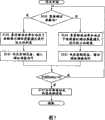
图7是本发明的第一个实施例中的控制序列的流程图。Fig. 7 is a flow chart of the control sequence in the first embodiment of the present invention.
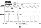
图8是显示在本发明的第一个实施例中,定影辊的温度的变化和电功率输入量之间的关系的示意图。Fig. 8 is a graph showing the relationship between the change in the temperature of the fixing roller and the electric power input amount in the first embodiment of the present invention.
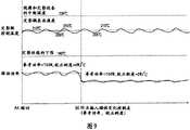
图9也是显示在本发明的第一个实施例中,定影辊的温度的变化和电功率输入量之间的关系的示意图。FIG. 9 is also a diagram showing the relationship between the change in the temperature of the fixing roller and the amount of electric power input in the first embodiment of the present invention.
图10显示第一个实施例中的用于控制提供到线圈的电功率量的值。Fig. 10 shows values for controlling the amount of electric power supplied to the coil in the first embodiment.
图11是本发明的第三个实施例中的控制序列的流程图。Fig. 11 is a flow chart of the control sequence in the third embodiment of the present invention.
图12显示在本发明的第三个实施例中,芯的纵向密度分布和定影辊的纵向表面温度分布之间的关系的示意图。Fig. 12 is a schematic diagram showing the relationship between the longitudinal density distribution of the core and the longitudinal surface temperature distribution of the fixing roller in the third embodiment of the present invention.
图13是本发明的第三个实施例中的基于感应的加热设备的等效电路。Fig. 13 is an equivalent circuit of an induction-based heating device in a third embodiment of the present invention.
图14显示在本发明的后面的实施例中,定影辊的纵向可加热范围的全部与定影辊的纵向可加热范围的被屏蔽了磁性的部分之间的近似关系的示意图。14 is a schematic diagram showing the approximate relationship between the entire longitudinal heatable range of the fixing roller and the magnetically shielded portion of the longitudinal heatable range of the fixing roller in the latter embodiment of the present invention.
具体实施方式Detailed ways
实施例1Example 1
(成像设备)(imaging equipment)
首先,将参考图2描述本实施例中的成像设备。感光鼓1作为图像承载构件被作为充电装置的充电辊2进行充电。感光鼓1的已充电的外围表面暴露于从作为曝光装置的基于激光的曝光设备的投射的激光束中,同时利用视频信号对该激光束进行调制。结果,在感光鼓1的外围表面上形成静电潜像。然后,基于感光鼓1的外围表面上的静电潜像,在感光鼓1的外围表面上,通过显影装置4形成可见的色粉影像。在感光鼓1上由调色剂构成的图像(下面将称为“色粉影像”)被转印到转印介质上,在本实施例中,转印介质是一张记录纸。顺便说一句,转印介质可以不同于本实施例中的转印介质;例如,可以是中间转印介质等等。在被转印到记录纸上之后,此时是未定影的图像的色粉影像通过定影装置7经加热定影到记录纸的表面上,关于这一点,稍后将进行描述。在转印色粉影像之后,通过诸如清理刀片等等之类的清理装置6去除感光鼓1的外围表面上保留的调色剂。当形成另一个图像时,重复与上文所描述的相同步骤。First, the imaging apparatus in this embodiment will be described with reference to FIG. 2 . The
(基于电磁感应的加热设备)(Heating equipment based on electromagnetic induction)
图4是本发明的第一个实施例中的作为图像加热设备的基于感应的加热设备的剖面图。Fig. 4 is a sectional view of an induction-based heating device as an image heating device in a first embodiment of the present invention.
作为图像加热构件的定影辊8的外径为40mm,壁厚为0.7mm,长度为340mm。它由金属铁芯、涂覆在金属铁芯的外围表面上的用于改善定影辊8的调色剂脱模特性(toner releasingproperty)的诸如PFA或PTFE之类的氟化树脂层构成,可以提供耐热弹性层,例如,设置在金属铁芯的外围表面和表面层之间的硅橡胶层。The
作为压力施加构件的压力辊9的外径为38mm,壁厚为3mm,长度为330mm。它由空心金属芯,以及在金属芯的外围表面上形成的、由具有调色剂脱模特性的耐热橡胶制成的绝热层构成。它可以具有诸如PFA或PTFE之类的氟化树脂层,作为用于改善压力辊9的调色剂脱模特性的表面层。The
加热辊8和压力辊9通过未显示的压力施加机制被可旋转地支撑,并彼此相对地施压,形成了一个固定夹,宽度大致为5mm,通过该夹N,记录介质可以被传递,同时保持被加热辊8和压力辊9夹住。加热辊8被未显示的马达以300mm/秒的圆周速度驱动,而压力辊9通过加热辊9的旋转,并使用加热辊8和压力辊9之间的固定夹N中的摩擦而旋转。作为本实施例中的记录介质的记录纸P被引入到固定夹N中,同时承载未定影的色粉影像t,并且当通过固定夹N传递记录纸P时,记录纸P上的未定影的色粉影像被固定夹N中的热和压力所定影。The
感应线圈13被由诸如PPS、PEEK、酚醛树脂等等之类的耐热磁性树脂中的某一种形成的支架支撑到芯12和支撑物17。其频率处于10-100kHz范围内的AC电流通过此感应线圈13流动,从而感应磁场,该磁场又在加热辊8的导电层中感应涡流电流。结果,在加热辊8的壁中产生热(焦耳热)。至于增大在加热辊8的壁中产生的热量的装置,可以增大线圈缠绕芯12的次数,使用诸如铁氧体、坡莫合金等等之类的导磁率高而剩余磁感应强度低的材料作为芯12的材料,以增大AC电流的频率,或使用类似的装置。The
作为磁性调整构件的调节器,以便它可以穿过线圈12和定影辊8之间的间隙。请参看图14,当定影辊8需要在其长度方向在其整个功能范围内被加热时,调节器保持在第一位置,即,后退位置14,而当它需要只在其中央部分加热时,即,当要通过定影设备传递的记录介质的大小小于利用定影设备传递的最大的(最宽的)记录介质的大小时,调节器被移到第二位置15,在该位置,调节器被直接放置在线圈12和定影辊8之间,以便对于定影辊8的不需要加热的那些部分屏蔽磁性。希望磁性调整构件由导电、无磁性,并且电阻率小的材料制成。例如,希望由铜、铝、银、其合金等等制成。本实施例中的磁性调整构件由铜制成。为了防止线圈12的温度提高,以及为了最小化磁性调整构件本身中产生的热量,希望磁性调整构件的电阻率小于图像加热构件的材料的电阻率。An adjuster as a magnetic adjustment member so that it can pass through the gap between the
为了进行下面的说明,可以把包括定影辊的热产生装置看作为简单的电路。For the following description, the heat generating means including the fixing roller can be regarded as a simple electrical circuit.
当利用下面公式(1),可以大致计算定影辊的壁中产生的热量W的量,在公式(1)中,字母I和R分别代表电流和电阻:When using the following formula (1), the amount of heat W generated in the wall of the fixing roller can be roughly calculated. In the formula (1), the letters I and R represent current and resistance respectively:
W∝I2·R ...(1)W∝I2 R...(1)
这里,将讨论当不调整磁性时和当调整磁性时两种情况之间产生的热量的差。Here, the difference in heat generation between the two cases when the magnetic properties are not adjusted and when the magnetic properties are adjusted will be discussed.
首先,将讨论公式(1)中的电阻R的变化。图5是加热装置的等效电路的简化版本,图5中的参考符号SW表示调节器的插入或缩回。感应加热还涉及线圈L。然而,为了简化,没有显示线圈L,只显示了加热中涉及的电阻R。符号Rcoil代表线圈的内阻。定影辊的电阻被分成两部分:定影辊的纵向中心部分的电阻RheatR-Center,以及定影辊的被磁性阻挡构件屏蔽了磁性的纵向末端部分的电阻RheatR-End。参考符号Rshut代表在插入磁性阻挡构件之后定影辊的纵向末端部分的电阻。电阻Rcoil的值可以通过测量施加于线圈的电压和流过线圈的电流量来获得。(Rcoil+RheatR-Center+RheatR-End)的值可以从当通过电磁感应对定影辊进行加热时流过的电流的量和施加的电压的幅值获得。RheatR-Center和RheatR-End之间的比率大致等于定影辊的没有被屏蔽磁性的纵向部分的长度以及定影辊的被屏蔽了磁性的纵向部分的总长度之间的比率。如此,可以轻松地获得RheatR-Center和RheatR-End的值,因为Rshut的值可以根据通过将磁性调整构件移动到磁性阻挡位置获得的(Rcoil+RheatR-Center+Rshutl)的值,以及如上所述获取的(Rcoil+RheatR-Center)的值来获得。在本实施例中,当周围温度为正常并且施加的AC电压为30kHz时获得的这些电阻值的比率是:First, changes in resistance R in formula (1) will be discussed. Fig. 5 is a simplified version of the equivalent circuit of the heating device, the reference symbol SW in Fig. 5 indicating the insertion or retraction of the regulator. Induction heating also involves the coil L. However, for simplicity, the coil L is not shown, only the resistance R involved in the heating is shown. The symbol Rcoil represents the internal resistance of the coil. The resistance of the fixing roller is divided into two parts: the resistance RheatR-Center of the longitudinal center portion of the fixing roller, and the resistance RheatR-End of the longitudinal end portions of the fixing roller magnetically shielded by the magnetic blocking member. Reference symbol Rshut represents the electrical resistance of the longitudinal end portion of the fixing roller after insertion of the magnetic blocking member. The value of resistance Rcoil can be obtained by measuring the voltage applied to the coil and the amount of current flowing through the coil. The value of (Rcoil +RheatR-Center +RheatR-End ) can be obtained from the amount of current flowing and the magnitude of applied voltage when the fixing roller is heated by electromagnetic induction. The ratio between RheatR-Center and RheatR-End is approximately equal to the ratio between the length of the non-magnetically shielded longitudinal portion of the fixing roller and the total length of the magnetically shielded longitudinal portion of the fixing roller. In this way, the values of RheatR-Center and RheatR-End can be easily obtained because the value of Rshut can be obtained according to the value of (Rcoil +RheatR-Center +Rshutl ) obtained by moving the magnetic adjustment member to the magnetic blocking position value, and the value of (Rcoil +RheatR-Center ) obtained as described above. In this embodiment, the ratio of these resistance values obtained when the ambient temperature is normal and the applied AC voltage is 30 kHz is:
Rcoil∶RheatR-Center∶RheatR-End∶Rshut=1∶28∶17∶2Rcoil : Rheat R-Center : Rheat R-End : Rshut = 1: 28: 17: 2
Rshut比较小的原因是调节器由铜制成,因此,单位面积的阻抗值比较小。The reason why Rshut is relatively small is that the regulator is made of copper, so the resistance value per unit area is relatively small.
当磁性没有被阻挡时加热装置的总电阻是:The total resistance of the heating device when the magnetism is not blocked is:
Rcoil+RheatR-Center+RheatR-End ...(2),Rcoil +Rheat R-Center +Rheat R-End ...(2),
而当磁性部分地被阻挡时加热装置的总电阻是:And the total resistance of the heating device when the magnetism is partially blocked is:
Rcoil+RheatR-Center+Rshut ...(3)Rcoil +Rheat R-Center +Rshut ...(3)
本实施例中的基于感应的加热设备通过利用一种普通功率控制方法来加以控制,以便提供给它的电功率的值保持恒定。具体来说,通过控制电流脉冲同时利用高频反相器来监视线圈的两个端子之间的电压,使提供到加热设备的电功率的值保持恒定。至于提供给高频反相器的电源,通过控制电流同时监视电压,可以使其保持恒定。使用上文所描述的控制的原因如下:产生的热量对定影设备是必不可少的,并且通过控制线圈电流的量来控制加热设备的方法允许提供到加热设备的电功率的值随着电压波动而波动。如此,对于普通设备使用此方法是不切实际的,因为普通设备在电功率的可用量方面是有限的。The induction-based heating device in this embodiment is controlled by using an ordinary power control method so that the value of electric power supplied thereto is kept constant. Specifically, the value of the electrical power supplied to the heating device is kept constant by controlling the current pulses while monitoring the voltage between the two terminals of the coil with a high frequency inverter. As for the power supplied to the high-frequency inverter, it can be kept constant by controlling the current while monitoring the voltage. The reason for using the above-described control is as follows: the heat generated is essential to the fixing device, and the method of controlling the heating device by controlling the amount of coil current allows the value of electric power supplied to the heating device to vary with voltage fluctuations. fluctuation. As such, it is impractical to use this method for common equipment, which is limited in the amount of electrical power available.
当输入到磁通量产生装置的功率P为Pin;电阻的总量为R;流过线圈的电流为I时,则流过电路的电流的量可通过下列公式(4)来表达:When the power P input to the magnetic flux generating device is Pin; the total amount of resistance is R; when the current flowing through the coil is I, the amount of current flowing through the circuit can be expressed by the following formula (4):
I=(Pin/R)1/2 ...(4)I=(Pin /R)1/2 ... (4)
这里,当磁性没有被阻挡时的电路的电阻RNB和当磁性部分地被阻挡时电路的电阻RB之间比率可以从下列公式(5)获得:Here, the ratio between the resistance RNB of the circuit when the magnetism is not blocked and the resistanceRB of the circuit when the magnetism is partially blocked can be obtained from the following formula (5):
RNB/RB=(Rcoil+RheatR_Center+RheatR_End)RNB /RB =(Rcoil +RheatR_Center +RheatR_End )
/(Rcoil+RheatR_Center+Rshut)=1.56/(Rcoil +RheatR_Center +Rshut )=1.56
根据公式(4),如果控制电功率输入Pin的值以便它保持恒定,则电流I的量响应于电阻R的值的变化而变化。根据公式(5),当磁性没有被阻挡时流过的电流I的量是当磁性部分地被阻挡时流过的电流量的1.25倍(=1.561/2)。According to the formula (4), if the value of the electric power input Pin is controlled so that it remains constant, the amount of the current I changes in response to the change of the value of the resistance R. According to formula (5), the amount of current I that flows when the magnetism is not blocked is 1.25 times (=1.561/2 ) the amount of current that flows when the magnetism is partially blocked.
换句话说,公式(1)中的电流I的量增大。因此,如果在磁性被阻挡时,通过给磁通量产生装置提供与在磁性没有被阻挡时要提供的相同的电功率量,由其中产生热量来对定影辊进行加热,则在线圈中产生的热量以及在定影辊的中心部分产生的热量增大到在磁性部分地被阻挡时产生的热量的1.56倍。In other words, the amount of current I in formula (1) increases. Therefore, if the fixing roller is heated by generating heat therefrom by supplying the magnetic flux generating means with the same amount of electric power as that to be supplied when the magnetism is not blocked when the magnetism is blocked, the heat generated in the coil and the The heat generated at the central portion of the fixing roller increased to 1.56 times that generated when the magnetism was partially blocked.
下面是本发明的发明人在考虑到上文所描述的问题的情况下所提出的实际控制方法。The following is an actual control method proposed by the inventors of the present invention in consideration of the problems described above.
在本实施例中,当磁性需要被阻挡时,基于不同于当磁性不需要被阻挡时所使用的磁场产生装置控制表,通过电磁感应来对定影辊进行加热。本实施例中的磁场产生装置控制表与用于驱动磁场产生装置所提供的电功率的量相关。它显示了电功率的基本量和调整比率。磁场产生装置控制表可以显示要流过磁通量产生装置的线圈电流的量,参数可以是记录介质类型、周围环境,等等。In this embodiment, when the magnetism needs to be blocked, the fixing roller is heated by electromagnetic induction based on the control table of the magnetic field generating device which is different from that used when the magnetism does not need to be blocked. The magnetic field generating device control table in this embodiment is related to the amount of electric power supplied for driving the magnetic field generating device. It shows the basic amount and adjustment ratio of electric power. The magnetic field generating device control table can display the amount of coil current to flow through the magnetic flux generating device, and the parameters can be recording medium type, surrounding environment, and the like.
这里,假设用户选择了使用A4大小的记录纸连续地制作多个副本的作业。图9显示了在执行作业时发生的定影辊的温度分布,以及电功率输入的量的变化。当使用A4大小的记录纸作为记录介质时,定影辊需要在其长度方向整体地进行加热,因此,磁性阻挡构件保持在后退位置。对于此作业,定影温度被保持在210℃。超过温度级别230℃,定影设备,具体来说是其线圈,将被损坏,低于温度级别180℃,图像定影将不会令人满意。根据图10中的表,为驱动磁通量产生装置而提供的电功率的基本量是700W,调整比率为4W/℃。控制设备16响应由位于如图4所示的定影设备的加热辊的附近的热敏电阻11检测到的温度级别,控制用于驱动磁通量产生装置的电功率15的量。具体来说,使用下列公式,响应获得的值,不断地改变电功率输入的量:Here, it is assumed that the user selects a job of continuously making a plurality of copies using A4-sized recording paper. FIG. 9 shows the temperature distribution of the fixing roller, and changes in the amount of electric power input, which occur when jobs are performed. When A4-sized recording paper is used as the recording medium, the fixing roller needs to be heated as a whole in its length direction, and therefore, the magnetic blocking member is held at the retracted position. For this job, the fixing temperature was kept at 210°C. Above the temperature level of 230°C, the fixing device, specifically its coil, will be damaged, and below the temperature level of 180°C, image fixing will not be satisfactory. According to the table in Fig. 10, the basic amount of electric power supplied for driving the magnetic flux generating means is 700W, and the adjustment ratio is 4W/°C. The
电功率输入的量=基本电功率输入的量+调整比率×(定影温度级别-检测到的温度级别) ...(8)The amount of electric power input = the amount of basic electric power input + adjustment ratio × (fixing temperature level - detected temperature level) ... (8)
当在给定时刻检测到的温度级别是203℃时,电功率输入的量被设置为740W(=700+4×(210-203)),即,使用公式(8)计算出的值。在下一时刻检测到的温度级别是213℃,因此,电功率输入的量被设置为708W,这是通过相同的计算获得的。在下一时刻检测到的温度级别是213℃,因此,电功率输入的量被设置为688W。通过重复这些步骤,加热辊的温度仍保持在210的附近,这是温度控制的预定的目标温度级别,虽然加热辊的温度会上下波动。在此控制之下温度波动的幅度为。换句话说,加热辊的温度高达215℃。When the temperature level detected at a given moment is 203° C., the amount of electric power input is set to 740 W (=700+4×(210−203)), that is, a value calculated using formula (8). The temperature level detected at the next moment is 213°C, therefore, the amount of electric power input is set to 708W, which is obtained by the same calculation. The temperature level detected at the next moment is 213° C., therefore, the amount of electric power input is set to 688W. By repeating these steps, the temperature of the heating roller is still maintained at around 210, which is the predetermined target temperature level of the temperature control, although the temperature of the heating roller fluctuates up and down. Under this control, the amplitude of the temperature fluctuation is . In other words, the temperature of the heating roller was as high as 215°C.
接下来,假设用户选择了使用B5大小的记录纸连续地制作多个副本的作业。当使用B5大小的记录纸来进行成像时,必须在加热辊的长度方向仅对其一部分进行加热。因此,一旦作业开始,就响应来自控制设备16的信号而插入磁性阻挡构件。参看图14,加热辊的对于此作业将要加热的那一部分,在加热辊的长度方向的尺寸大致与B5大小的记录介质的宽度相同。如此,如果由于诸如上文所描述的原因输入了与为前面的作业输入的电功率相同的电功率量,则加热辊的中心部分的温度升高将会变得较大;向上的温度波动的检测到的幅度是向上+30℃,向下-10℃。如此,如果图像定影的温度级别仍停留在210℃,则加热辊的中心部分的温度级别已高达240℃,在该温度或超过该温度,线圈将被损坏。温度波动的幅度高达40℃。因此,未定影的图像的将在温度波动的顶端被定影的那些部分的光泽度级别将不同于未定影的图像的将在温度波动的底端定影的那些部分。换句话说,记录介质和其上面的图像的光泽度将不均匀。因此,在本实施例中,一旦开始阻挡磁性,控制表就被切换到图10所示的控制表。即,提供到磁通量产生装置的电功率的基本量,以及调整比率,被切换到500W和2W/℃,而图像定影的温度级别仍保持在210℃。这些变化,温度波动的幅度减少到,与磁性没有被阻挡期间相同。因此,加热辊的中心部分的温度不高于215℃,也不会低于205℃。换句话说,不仅不会产生过度的温度上升,而且进行了定影,而不会发生光泽度不均匀的问题。Next, assume that the user selects a job of continuously making a plurality of copies using B5-sized recording paper. When image formation is performed using recording paper of B5 size, it is necessary to heat only a part of the heating roller in its lengthwise direction. Thus, the magnetic blocking member is inserted in response to a signal from the
接下来,将参考图7中的流程图比较详细地描述此过程。Next, this process will be described in more detail with reference to the flowchart in FIG. 7 .
首先,在步骤S100中,输入要执行的作业的类型。在步骤S101中,判断是否需要通过磁性调整构件来阻挡磁性。例如,当记录纸的宽度等于在垂直于记录介质传送方向的方向A4大小的记录纸的宽度时,则判断磁性不需要被阻挡,而如果它不大于B5大小的记录纸的宽度,则判断磁性需要部分地被阻挡。此外,如果加热辊的在记录介质路径外部的那些部分的温度上升到超过传递其宽度不超过B5大小的记录纸时用于图像定影的预先确定的级别,则判断磁性需要部分地被阻挡。当磁性需要部分地被阻挡时,采取步骤S102,其中,输入磁性阻挡信号时,已经使用的电功率的基本量和对应的调整比率被切换到当磁性需要部分地被阻挡时的那些量。然后,开始移动磁性调整构件(S103)。First, in step S100, the type of job to be executed is input. In step S101, it is judged whether the magnetism needs to be blocked by a magnetic adjustment member. For example, when the width of the recording paper is equal to the width of the recording paper of the size A4 in the direction perpendicular to the conveying direction of the recording medium, it is judged that the magnetic properties do not need to be blocked, and if it is not larger than the width of the recording paper of the B5 size, it is judged that the magnetic properties do not need to be blocked. Need to be partially blocked. Furthermore, if the temperature of those parts of the heating roller outside the recording medium path rises above a predetermined level for image fixing when conveying recording paper whose width does not exceed the B5 size, it is judged that the magnetism needs to be partially blocked. When the magnetic needs are partially blocked, step S102 is taken, wherein, when the magnetic blocking signal is input, the basic amount of electric power that has been used and the corresponding adjustment ratio is switched to those amounts when the magnetic needs are partially blocked. Then, the movement of the magnetic adjustment member is started (S103).
在移动磁性阻挡构件之前或与此同时,在移动磁性阻挡构件时要提供的电功率的量(第二功率控制)必须切换到正常操作过程中(当磁性不需要部分地被阻挡时)要提供的电功率的量(第一功率控制)。在本实施例中,当移动磁性调整构件时,以及在磁性调整构件被移到第二位置之后,使用相同的功率控制。然而,可以使得当移动磁性调整构件时使用的功率控制不同于在磁性调整构件被移到第二位置之后使用的功率控制,并且这将不会导致任何问题。如果在步骤S101中判断磁性不需要部分地被阻挡,则执行正常功率控制(S104),并确认磁性调整构件处于第一位置(S105)。然后,判断作业是否已经完成(S106)。如果确认作业已经完成,则将定影设备置于待机状态(S107),并结束操作(S108)。Before or at the same time as moving the magnetic blocking member, the amount of electrical power to be provided when moving the magnetic blocking member (second power control) must be switched to that to be provided during normal operation (when the magnetism does not need to be partially blocked) Amount of electric power (first power control). In this embodiment, the same power control is used when moving the magnetic adjustment member, and after the magnetic adjustment member has been moved to the second position. However, it is possible to make the power control used when moving the magnetic adjustment member different from the power control used after the magnetic adjustment member has been moved to the second position, and this will not cause any problems. If it is judged in step S101 that the magnetism does not need to be partially blocked, normal power control is performed (S104), and it is confirmed that the magnetism adjusting member is in the first position (S105). Then, it is judged whether the job has been completed (S106). If it is confirmed that the job has been completed, the fixing device is placed in a standby state (S107), and the operation is ended (S108).
图像定影所需的电功率的量受到待加热的对象的类型,即,记录纸的类型等等的影响。因此,通过在与开始对磁性进行部分阻挡的同时,在将电功率输入的量切换到500W之后,即,移动电功率输入的量的中值,来执行在本实施例中的控制,可以使定影辊的温度保持恒定,如图1所示。至于这期间的线圈的温度,不管磁性是否部分地被阻挡,以及记录纸的类型如何,它都保持恒定。The amount of electric power required for image fixing is affected by the type of object to be heated, that is, the type of recording paper, and the like. Therefore, by performing the control in this embodiment after switching the amount of electric power input to 500 W, that is, shifting the median value of the amount of electric power input, while starting to partially block magnetism, it is possible to make the fixing roller The temperature is kept constant, as shown in Figure 1. As for the temperature of the coil during this period, it remains constant regardless of whether the magnetism is partially blocked or not, and the type of recording paper.
在本实施例中:In this example:
接下来,假设用户选择了使用A4大小的记录纸连续地制作多个副本的作业。图8显示了在执行作业时发生的温度分布,以及电功率输入的量的变化。当使用A4大小的记录纸时,定影辊需要在其长度方向整体地进行加热。因此,磁性阻挡构件保持在退后位置。对于此作业,用于图像定影的目标温度级别被设置为210℃。超过温度级别230℃,定影设备,具体来说是其线圈,将被损坏,低于温度级别180℃,图像定影将不会令人满意。为驱动磁通量产生装置而提供的电功率的基本量是800W。响应由热敏电阻检测到的定影辊的温度,打开或关闭用于驱动磁通量产生装置的电源。温度波动的量是
接下来,假设用户选择了使用B5大小的记录纸连续地制作多个副本的作业。当使用B5大小的记录纸来进行成像时,必须在加热辊的长度方向对其仅一部分进行加热。因此,一旦作业开始,就插入磁性阻挡构件。在不对控制进行改变的情况下,加热辊的温度将达到240℃,超过该温度,线圈将被损坏,如在第一实施例中那样。如此,当磁性部分地被阻挡时提供的电功率的量被设置为700W,同时将目标温度保持在210℃。在对该控制进行此修改的情况下,温度波动的量减少到
存在这样的可能性:如果插入了磁性调整构件,同时电功率输入的量被保持在与当磁性调整构件不在磁性调整位置时输入的电功率的量相同的级别,则用于驱动磁通量产生装置的电源将被插入磁性调整构件的瞬间流动的过度的电流量(冲击电流)损坏。是否发生此现象取决于电源的容量。因此,此问题,或电源的损坏,可以通过确保在电功率输入的量被切换到在调整磁性时要提供的电功率的量之后插入磁性调整构件来加以防止。There is a possibility that if the magnetic adjustment member is inserted while the amount of electric power input is maintained at the same level as the amount of electric power input when the magnetic adjustment member is not in the magnetic adjustment position, the power source for driving the magnetic flux generating device will It is damaged by the excessive amount of electric current (rush current) flowing momentarily inserted into the magnetic adjustment member. Whether this phenomenon occurs depends on the capacity of the power supply. Therefore, this problem, or damage to the power supply, can be prevented by ensuring that the magnetic adjustment member is inserted after the amount of electrical power input is switched to the amount of electrical power to be supplied when adjusting the magnetic properties.
然而,降低当磁性部分地被阻挡时要提供的电功率的量,可以提高电磁感应对加热辊进行加热的效率。由于在线圈本身中产生热量而丢失的提供到加热装置的电功率的量Wloss-coil可以按如下方式表示,并考虑到负载,即,单位时间长度内电流流过线圈的时间长度的比率:However, reducing the amount of electric power to be supplied when the magnetism is partially blocked improves the efficiency of heating the heating roller by electromagnetic induction. The amount Wloss-coil of the electrical power supplied to the heating device that is lost due to heat generation in the coil itself can be expressed as follows, taking into account the load, that is, the ratio of the length of time that current flows through the coil per unit length of time:
Wloss-coil=Icoil2×Rcoil×负载Wloss-coil = Icoil2 × Rcoil × load
如果电源被打开的时间长度的比率为20%,则磁通量产生装置被驱动的平均量为160W。假设电源的电压是100V,当控制设置被保持为原始值时,线圈丢失的电功率的量Wloss-coil可以使用下列公式来进行计算:If the ratio of the length of time that the power is turned on is 20%, the average amount by which the magnetic flux generating means is driven is 160W. Assuming that the voltage of the power supply is 100V, when the control setting is kept at the original value, the amount of electrical power lost by the coil Wloss-coil can be calculated using the following formula:
Wloss-coil 800W=(800/100)2·Rcoil·(20/100)Wloss-coil 800W =(800/100)2 ·Rcoil ·(20/100)
Wloss-coil 160W=(160/100)2·Rcoil·(100/100)Wloss-coil 160W =(160/100)2 ·Rcoil ·(100/100)
因此,通过分别将当磁性部分地被阻挡时要提供的电功率的量和负载改变为160W和100%,功率损耗的量可以减少到1/5(=Wloss-coil-160W/Wloss-coil-800W),从而增大功率的有效量。Therefore, by changing the amount of electrical power and load to be supplied when the magnetism is partially blocked to 160W and 100% respectively, the amount of power loss can be reduced to 1/5 (=Wloss-coil-160W /Wloss-coil -800W ), thereby increasing the effective amount of power.
如果在插入磁性阻挡构件之前已经给磁通量产生装置提供了适当的功率量,则插入磁性阻挡构件而不改变电功率输入的量将提高如上所述的损耗量。如此,当需要部分地阻挡磁性时,通过切换电功率输入的量,提供到磁通量产生装置的电功率的有效量可以得到提高,如在本实施例中那样。换句话说,当输入磁性阻挡信号时,在功率控制被切换到当移动磁性阻挡构件时要使用的功率控制的同时,或在输入磁性阻挡信号之后预先确定的时间长度,或响应于磁性阻挡构件移动开始信号,将移动磁性调整构件。Inserting the magnetic blocking member without changing the amount of electrical power input will increase the amount of losses as described above if the magnetic flux generating means has been supplied with an appropriate amount of power prior to insertion of the magnetic blocking member. As such, the effective amount of electrical power supplied to the magnetic flux generating means can be increased by switching the amount of electrical power input when partial magnetic blocking is desired, as in this embodiment. In other words, when the magnetic blocking signal is input, while the power control is switched to the power control to be used when moving the magnetic blocking member, or after a predetermined length of time after the magnetic blocking signal is input, or in response to the magnetic blocking member Moving the start signal will move the magnetic adjustment member.
在上文中,描述了在插入磁性调整构件紧前面改变电功率输入的量的控制方法。然而,也可以改变电功率控制表本身。In the above, the control method of changing the amount of electric power input immediately before inserting the magnetic adjustment member has been described. However, it is also possible to change the electric power control table itself.
实施例2Example 2
本实施例中的图像加热设备的结构基本上与第一个实施例中的结构相同。然而,在本实施例中,不是改变电功率输入的量,而是使得当磁性需要部分地被阻挡时定影辊的温度将被保持的目标温度级别低于当磁性不需要部分地被阻挡时的目标温度级别,如下文所述的。The structure of the image heating apparatus in this embodiment is basically the same as that in the first embodiment. However, in this embodiment, instead of changing the amount of electric power input, the target temperature level at which the temperature of the fixing roller is to be maintained when the magnetism needs to be partially blocked is made lower than the target when the magnetism does not need to be partially blocked. temperature class, as described below.
图6显示在用户选择了使用A4大小的记录纸连续地制作多个副本的作业之后发生的定影辊的温度分布,以及电功率输入的量的变化。当使用A4大小的记录纸作为记录介质时,定影辊需要在其长度方向整体地进行加热,因此,磁性阻挡构件保持在退后位置。对于此作业,目标温度级别,或定影辊的温度将被保持的温度级别,为210℃。超过温度级别230℃,定影设备,具体来说是其线圈,将被损坏,低于温度级别180℃,图像定影将不会令人满意。电功率输入的量为800W。响应由位于加热辊附近的热敏电阻检测到的定影设备的加热辊的温度来打开或关闭感应加热设备的电源。在此作业期间发生的温度波动的振幅相对于目标温度为。换句话说,加热辊的温度可高达220℃。FIG. 6 shows the temperature distribution of the fixing roller, and changes in the amount of electric power input that occur after the user selects a job of continuously making a plurality of copies using A4-sized recording paper. When A4-sized recording paper is used as the recording medium, the fixing roller needs to be heated as a whole in its length direction, and therefore, the magnetic blocking member is held at the retracted position. For this job, the target temperature level, or the temperature level at which the temperature of the fuser roller is to be maintained, is 210°C. Above the temperature level of 230°C, the fixing device, specifically its coil, will be damaged, and below the temperature level of 180°C, image fixing will not be satisfactory. The amount of electric power input was 800W. The power of the induction heating device is turned on or off in response to the temperature of the heating roller of the fixing device detected by the thermistor located near the heating roller. The amplitude of temperature fluctuations that occur during this operation relative to the target temperature is . In other words, the temperature of the heating roller can be as high as 220°C.
接下来,用户选择了使用B5大小的记录纸连续地制作多个副本的作业。当使用B5大小的记录纸来进行成像时,必须在加热辊的长度方向对其仅一部分进行加热。因此,一旦作业开始,就插入磁性阻挡构件。在不对控制作出改变的情况下,加热辊的中心部分的温度将会过度地上升;测试显示,温度波动的振幅在+侧为30℃,而在-侧为10℃。换句话说,在目标温度保持在210℃的情况下,加热辊的中心部分的温度将高达240℃,该温度高到足以使线圈损坏。因此,在本实施例中,在磁性部分地被阻挡时加热辊的温度将被保持到的目标温度级别被设置为195℃。由于辐射,定影辊的表面温度在纵向末端部分趋于低于中心部分。此外,在定影辊的长度方向的定影辊的中心部分附近设置热敏电阻。因此,当使用A4大小的记录介质来进行成像时,定影辊的在位置方面对应于记录介质的宽度方向中记录介质的边缘部分的那些部分的温度有时下降到180℃,即使目标温度被设置为210℃。比较起来,定影辊的在B5大小的记录介质的路径内的那一部分的温度的不均匀性程度小于定影辊在A4大小的记录介质的路径内的那一部分的温度不均匀性程度。如此,即使目标温度被设置为195℃,定影辊的在位置方面对应于B5大小的记录介质的边缘部分的那一部分的温度所下降到的最低温度级别将不低于180℃。因此,在使用本实施例中的控制方法的情况下,加热辊的中心部分所达到的最高温度级别为225℃,而定影辊的中心部分所下降到的最低温度级别为185℃。因此,图像被令人满意地定影,而不存在有关温度过度升高的问题。Next, the user selects a job of continuously making a plurality of copies using B5-sized recording paper. When image formation is performed using recording paper of B5 size, it is necessary to heat only a part of the heating roller in its lengthwise direction. Therefore, once the work starts, the magnetic blocking member is inserted. Without a change in control, the temperature of the central part of the heating roller would rise excessively; tests showed that the amplitude of the temperature fluctuation was 30°C on the + side and 10°C on the -side. In other words, in the case where the target temperature is kept at 210°C, the temperature of the central portion of the heating roller will be as high as 240°C, which is high enough to damage the coil. Therefore, in the present embodiment, the target temperature level to which the temperature of the heating roller is to be maintained when the magnetism is partially blocked is set to 195°C. Due to radiation, the surface temperature of the fixing roller tends to be lower at the longitudinal end portions than at the central portion. In addition, a thermistor is provided near the central portion of the fixing roller in the longitudinal direction of the fixing roller. Therefore, when image formation is performed using an A4-sized recording medium, the temperature of those portions of the fixing roller corresponding in position to the edge portion of the recording medium in the width direction of the recording medium sometimes drops to 180° C. even if the target temperature is set to 210°C. In comparison, the degree of temperature unevenness of the portion of the fixing roller within the path of the B5 size recording medium is smaller than that of the portion of the fixing roller within the path of the A4 size recording medium. Thus, even if the target temperature is set to 195°C, the lowest temperature level to which the temperature of the portion of the fixing roller corresponding in position to the edge portion of the B5-sized recording medium falls will not be lower than 180°C. Therefore, in the case of using the control method in this embodiment, the highest temperature level reached by the central portion of the heating roller is 225°C, and the lowest temperature level to which the central portion of the fixing roller falls is 185°C. Therefore, the image was satisfactorily fixed without problems regarding an excessive rise in temperature.
此时,将参考图11描述本实施例中的控制序列。At this time, the control sequence in this embodiment will be described with reference to FIG. 11 .
首先,在步骤S400中,输入表示所选择的成像作业的信号。在步骤S401中,判断是否有必要通过磁性调整构件部分地阻挡磁性。例如,当记录纸的宽度等于在垂直于记录介质传送方向的方向中A4大小的记录纸的宽度时,则判断磁性不需要部分地被阻挡,而如果它不大于B5大小的记录纸的宽度时,则判断磁性需要部分地被阻挡。然后,当需要对磁性进行部分阻挡时,采取步骤S402,其中,当输入磁性阻挡信号时,目标温度被切换到195。然后,开始移动磁性调整构件的过程(S103)。First, in step S400, a signal representing a selected imaging job is input. In step S401, it is judged whether it is necessary to partially block the magnetism by the magnetism adjusting member. For example, when the width of the recording paper is equal to the width of the recording paper of the A4 size in the direction perpendicular to the conveying direction of the recording medium, it is judged that the magnetism does not need to be partially blocked, while if it is not larger than the width of the recording paper of the B5 size , it is judged that the magnetism needs to be partially blocked. Then, when partial blocking of the magnetism is required, step S402 is taken, wherein the target temperature is switched to 195 when the magnetic blocking signal is input. Then, the process of moving the magnetic adjustment member starts (S103).
在插入磁性阻挡构件之前,或与此同时,在移动磁性调整构件时要使用的用于温度控制的目标温度级别必须切换到用于温度控制的正常目标温度级别(在磁性不被阻挡时要使用的目标温度级别)。在本实施例中,使用与当移动磁性调整构件时用于温度控制的温度级别相同的温度级别作为在将磁性调整构件移动到第二位置之后用于进行温度控制的目标温度级别。然而,在将磁性调整构件移动到第二位置之后所使用的进行温度控制的目标温度级别可以不同于当移动磁性阻挡构件时用于进行温度控制的温度级别,只要前者低于用于温度控制的正常目标温度级别即可。当在步骤S401中判断磁性不需要被阻挡时,执行正常的电功率控制(S404)。然后,判断磁性调整构件是否处于第一位置(S405)。然后,判断作业是否已经完成(S406)。当判断作业已经完成时,将定影设备置于待机状态(S407),并结束操作(S408)。Before inserting the magnetic blocking member, or at the same time, the target temperature level for temperature control to be used when moving the magnetic adjustment member must be switched to the normal target temperature level for temperature control (to be used when the magnetic is not blocked target temperature level). In this embodiment, the same temperature level as that used for temperature control when moving the magnetic adjustment member is used as the target temperature level for temperature control after moving the magnetic adjustment member to the second position. However, the target temperature level for temperature control used after moving the magnetic adjustment member to the second position may be different from the temperature level for temperature control when moving the magnetic blocking member, as long as the former is lower than the target temperature level for temperature control. The normal target temperature level is sufficient. When it is judged in step S401 that the magnetism does not need to be blocked, normal electric power control is performed (S404). Then, it is judged whether the magnetic adjustment member is in the first position (S405). Then, it is judged whether the job has been completed (S406). When it is judged that the job has been completed, the fixing device is placed in a standby state (S407), and the operation is ended (S408).
实施例3Example 3
本实施例中的图像加热设备的结构基本上与第一个实施例中的结构相同。然而,在本实施例中,使磁场产生装置的芯在其纵向末端部分的密度比在中心部分的密度更大。The structure of the image heating apparatus in this embodiment is basically the same as that in the first embodiment. However, in this embodiment, the core of the magnetic field generating means is made denser at its longitudinal end portions than at its central portion.
为了减少定影设备的电功率消耗和预热时间,时常需要降低加热构件的热容量。然而,如果加热构件的热容量降低,则可以存储在其中的热量变得相当小,因此,加热构件的温度减小的量较大,尤其在加热辊的纵向末端部分,因为,与加热辊的中心部分不同,这些部分(热源)不会在其长度方向从两侧暴露于电磁通量中,此外,还有许多热辐射源,如马达、齿轮,等等,它们位于加热构件的纵向末端部分的附近。换句话说,如果加热构件的热容量降低,则会发生加热构件在纵向末端部分的温度比其中心部分的温度低得多的问题。作为防止此问题的一个方法,通过使芯的末端部分的密度大于芯的中心部分的密度,以便使加热构件的纵向末端部分的磁通密度比加热构件的中心部分的磁通密度更大,可以调整在加热构件的纵向末端部分中产生的热量。当使用此方法时,上文所提及的不同的电阻之间的比率是:In order to reduce the electric power consumption and warm-up time of the fixing device, it is often necessary to reduce the heat capacity of the heating member. However, if the heat capacity of the heating member is reduced, the amount of heat that can be stored therein becomes considerably smaller, and therefore, the amount of temperature reduction of the heating member is larger, especially at the longitudinal end portion of the heating roller, because, unlike the center of the heating roller different parts, these parts (heat sources) are not exposed to electromagnetic flux from both sides in the direction of their length, in addition, there are many sources of heat radiation, such as motors, gears, etc., which are located in the vicinity of the longitudinal end parts of the heating member . In other words, if the heat capacity of the heating member is lowered, there occurs a problem that the temperature of the heating member is much lower at the longitudinal end portions than at the central portion thereof. As a method of preventing this problem, by making the density of the end portion of the core higher than that of the central portion of the core so that the magnetic flux density of the longitudinal end portion of the heating member is larger than that of the central portion of the heating member, it is possible to The amount of heat generated in the longitudinal end portion of the heating member is adjusted. When using this method, the ratio between the different resistors mentioned above is:
Rcoil∶RheatR-Center∶RheatR-End∶Rshut=1∶20∶25∶2。Rcoil : Rheat R-Center : Rheat R-End : Rshut = 1:20:25:2.
在此情况下,芯的纵向中心部分比芯的纵向末端部分密度低。因此,如果插入磁性阻挡构件而不对控制序列进行某些修改,则在芯中产生的热量大于当芯的纵向末端部分的密度与芯的纵向中心部分的密度相同时在芯中产生的热量。在第一个实施例中,当磁性部分地被阻挡时,线圈中产生的热量是当磁性没有被阻挡时线圈中产生的热量的1.56倍。然而,在本实施例中,即,当芯的纵向末端部分的密度大于芯的纵向中心部分的密度时,根据公式(5),当磁性部分地被阻挡时线圈中产生的热量将变为当磁性没有被阻挡时线圈中产生的热量的2.00倍,除非对控制序列进行了某些修改。此外,本实施例中的加热构件的电阻R在被磁性调整构件屏蔽的部分减少的量大于第一个实施例中的减少量。因此,电流增大的量变得更大。因此,如果插入了磁性阻挡装置而不改变目标温度、电功率输入的量、控制的系数等等,在第一个到第三个实施例的说明中提到的问题将变得明显。In this case, the longitudinal central portion of the core is less dense than the longitudinal end portions of the core. Therefore, if the magnetic blocking member is inserted without some modification of the control sequence, the heat generated in the core is greater than if the longitudinal end portions of the core have the same density as the longitudinal central portion of the core. In the first embodiment, when the magnetism is partially blocked, the heat generated in the coil is 1.56 times the heat generated in the coil when the magnetism is not blocked. However, in this embodiment, that is, when the density of the longitudinal end portion of the core is greater than that of the longitudinal center portion of the core, according to the formula (5), the heat generated in the coil when the magnetism is partially blocked will become when 2.00 times the heat generated in the coil when the magnetism is not blocked, unless certain modifications are made to the control sequence. In addition, the resistance R of the heating member in this embodiment is reduced by a larger amount at the portion shielded by the magnetic adjustment member than in the first embodiment. Therefore, the amount of current increase becomes larger. Therefore, if the magnetic blocking means is inserted without changing the target temperature, the amount of electric power input, the coefficient of control, etc., the problems mentioned in the description of the first to third embodiments will become apparent.
然而,只要目标温度、电功率输入的量、控制调整表中的一个,或其任何组合,或它们中的全部被改变,如在本发明的本实施例中那样,在磁性部分地被阻挡之前,或与此同时,将获得其满意度级别对应于所选择的改变的类型的满意效果。即,上文所描述的问题,如,电源被涡流电流损坏;定影设备,具体来说是其线圈,被加热构件的温度的过度升高所损坏;产生光泽度不一致的副本,等等,不会发生,并且本实施例中的定影设备的性能与其芯的密度在其长度方向跨整体是均匀的定影设备的性能一样令人满意。However, as soon as one of the target temperature, the amount of electrical power input, the control adjustment table, or any combination thereof, or all of them are changed, as in this embodiment of the invention, before the magnetics are partially blocked, Or at the same time, a satisfactory effect will be obtained whose satisfaction level corresponds to the type of change selected. That is, the problems described above, such as that the power supply is damaged by eddy current; that the fixing device, specifically its coil, is damaged by an excessive rise in the temperature of the heating member; that copies with inconsistent glossiness are produced, etc., do not occurred, and the performance of the fixing device in this embodiment was as satisfactory as that of a fixing device whose core density in its lengthwise direction was uniform across the whole.
尽管参考这里所说明的结构描述了本发明,但是,它不只限于所阐述的细节,本申请涵盖这样的修改或改变,只要它们在下列权利要求的范围内,或在对它们的改进的范围内。Although the invention has been described with reference to the structures illustrated herein, it is not limited to the details set forth and the application covers such modifications or changes as long as they come within the scope of the following claims, or within the scope of improvements to them .
Claims (13)
Translated fromChineseApplications Claiming Priority (3)
| Application Number | Priority Date | Filing Date | Title |
|---|---|---|---|
| JP2004308337 | 2004-10-22 | ||
| JP2004-308337 | 2004-10-22 | ||
| JP2004308337 | 2004-10-22 |
Related Child Applications (1)
| Application Number | Title | Priority Date | Filing Date |
|---|---|---|---|
| CN200810170426.6ADivisionCN101414148B (en) | 2004-10-22 | 2005-10-21 | Image heating equipment |
Publications (2)
| Publication Number | Publication Date |
|---|---|
| CN1770037A CN1770037A (en) | 2006-05-10 |
| CN1770037Btrue CN1770037B (en) | 2012-02-22 |
Family
ID=35652350
Family Applications (2)
| Application Number | Title | Priority Date | Filing Date |
|---|---|---|---|
| CN200510116389.7AActiveCN1770037B (en) | 2004-10-22 | 2005-10-21 | Image heating equipment |
| CN200810170426.6AActiveCN101414148B (en) | 2004-10-22 | 2005-10-21 | Image heating equipment |
Family Applications After (1)
| Application Number | Title | Priority Date | Filing Date |
|---|---|---|---|
| CN200810170426.6AActiveCN101414148B (en) | 2004-10-22 | 2005-10-21 | Image heating equipment |
Country Status (5)
| Country | Link |
|---|---|
| US (3) | US8099008B2 (en) |
| EP (1) | EP1650611B1 (en) |
| JP (1) | JP4850982B2 (en) |
| CN (2) | CN1770037B (en) |
| DE (1) | DE602005014838D1 (en) |
Families Citing this family (24)
| Publication number | Priority date | Publication date | Assignee | Title |
|---|---|---|---|---|
| JP4717412B2 (en) | 2004-10-22 | 2011-07-06 | キヤノン株式会社 | Heating device |
| US7251428B2 (en) | 2004-10-22 | 2007-07-31 | Canon Kabushiki Kaisha | Image forming apparatus with heating rotatable member and reset control means for interrupting a currently executing image formation job |
| JP4208816B2 (en) | 2004-10-22 | 2009-01-14 | キヤノン株式会社 | Image heating device |
| JP4208815B2 (en)* | 2004-10-22 | 2009-01-14 | キヤノン株式会社 | Image heating device |
| CN1770037B (en)* | 2004-10-22 | 2012-02-22 | 佳能株式会社 | Image heating equipment |
| JP4731982B2 (en)* | 2005-04-28 | 2011-07-27 | キヤノン株式会社 | Image heating device |
| JP4756967B2 (en)* | 2005-09-14 | 2011-08-24 | キヤノン株式会社 | Image heating device |
| US20110064441A1 (en)* | 2009-09-15 | 2011-03-17 | Kabushiki Kaisha Toshiba | Temperature Control Method for Fixing Device |
| JP5503248B2 (en)* | 2009-10-19 | 2014-05-28 | キヤノン株式会社 | Image heating device |
| JP2011090087A (en)* | 2009-10-21 | 2011-05-06 | Canon Inc | Image heating device |
| JP5773774B2 (en) | 2011-06-24 | 2015-09-02 | キヤノン株式会社 | Image heating device and C-shaped retaining ring |
| JP5383868B2 (en) | 2011-06-24 | 2014-01-08 | キヤノン株式会社 | Image heating apparatus and recording material conveying apparatus |
| JP5904748B2 (en) | 2011-10-14 | 2016-04-20 | キヤノン株式会社 | Image heating device |
| JP6071306B2 (en)* | 2012-07-30 | 2017-02-01 | キヤノン株式会社 | Image heating device |
| JP6137893B2 (en) | 2013-03-22 | 2017-05-31 | キヤノン株式会社 | Heating apparatus and image forming apparatus |
| US20140363326A1 (en) | 2013-06-10 | 2014-12-11 | Grid Logic Incorporated | System and method for additive manufacturing |
| US10350683B2 (en) | 2013-10-02 | 2019-07-16 | Grid Logic Incorporated | Multiple flux concentrator heating |
| US10241850B2 (en) | 2013-10-02 | 2019-03-26 | Grid Logic Incorporated | Non-magnetodielectric flux concentrator |
| JP2015096922A (en) | 2013-11-15 | 2015-05-21 | キヤノン株式会社 | Image forming apparatus, controller, and control method thereof |
| JP6282141B2 (en) | 2014-03-03 | 2018-02-21 | キヤノン株式会社 | Fixing device |
| EP4353384A3 (en) | 2016-02-03 | 2024-06-26 | Grid Logic Incorporated | System and method for manufacturing a part |
| WO2021226531A2 (en) | 2020-05-08 | 2021-11-11 | Grid Logic Incorporated | System and method for manufacturing a part |
| CN112462816B (en)* | 2020-10-30 | 2022-07-29 | 北京空间飞行器总体设计部 | Self-adaptive temperature control method for improving temperature stability of system |
| CN117270356A (en)* | 2023-09-26 | 2023-12-22 | 珠海奔图电子有限公司 | Printing control method and device, image forming apparatus, and storage medium |
Citations (1)
| Publication number | Priority date | Publication date | Assignee | Title |
|---|---|---|---|---|
| CN1525266A (en)* | 2003-02-28 | 2004-09-01 | ������������ʽ���� | Image heating plant |
Family Cites Families (35)
| Publication number | Priority date | Publication date | Assignee | Title |
|---|---|---|---|---|
| JPS5672470A (en)* | 1979-11-20 | 1981-06-16 | Konishiroku Photo Ind Co Ltd | Temperature control method of heat roller type fixing device |
| JPS58200262A (en)* | 1982-05-19 | 1983-11-21 | Canon Inc | Heat roll fixing device |
| JPS5933787A (en) | 1982-08-19 | 1984-02-23 | 松下電器産業株式会社 | High frequency induction heating roller |
| JPS5945475A (en)* | 1982-09-08 | 1984-03-14 | Fuji Xerox Co Ltd | Temperature control device for fixation device of heating roll type |
| JPH0711376B2 (en) | 1988-01-28 | 1995-02-08 | 三洋電機株式会社 | Ice bank type water cooler |
| US5464964A (en) | 1991-12-11 | 1995-11-07 | Canon Kabushiki Kaisha | Image heating apparatus changing set temperature in accordance with temperature of heater |
| JPH08220912A (en) | 1995-02-17 | 1996-08-30 | Canon Inc | Fixing device by electromagnetic induction heating |
| JP3624040B2 (en) | 1995-12-20 | 2005-02-23 | キヤノン株式会社 | Heating device |
| EP0797130B1 (en) | 1996-03-21 | 2001-10-10 | Canon Kabushiki Kaisha | Image heating apparatus |
| JP2000122466A (en)* | 1998-10-19 | 2000-04-28 | Canon Inc | Image forming device |
| JP2000321903A (en)* | 1999-05-12 | 2000-11-24 | Ricoh Co Ltd | Induction heating type fixing device |
| JP2002006677A (en)* | 2000-06-20 | 2002-01-11 | Dainippon Printing Co Ltd | Magnetic printer |
| JP4545899B2 (en) | 2000-07-31 | 2010-09-15 | キヤノン株式会社 | Heating apparatus and image forming apparatus |
| US6516166B2 (en)* | 2000-09-28 | 2003-02-04 | Canon Kabushiki Kaisha | Image fixing apparatus |
| US6643476B1 (en) | 2000-10-31 | 2003-11-04 | Kabushiki Kaisha Toshiba | Image forming apparatus with accurate temperature control for various media having different thickness |
| JP3814543B2 (en)* | 2001-02-23 | 2006-08-30 | キヤノン株式会社 | Image heating device |
| JP3880326B2 (en) | 2001-03-26 | 2007-02-14 | キヤノン株式会社 | Heating device and image forming apparatus provided with the heating device |
| JP2003098897A (en) | 2001-09-25 | 2003-04-04 | Canon Inc | Heating device and image forming device |
| KR100389872B1 (en)* | 2001-11-12 | 2003-07-04 | 삼성전자주식회사 | Method and apparatus for controlling power for fusing roller of electrophotographic image forming apparatus |
| JP2003168549A (en)* | 2001-12-04 | 2003-06-13 | Canon Inc | Heating device, heat fixing device, and image forming device |
| JP2004163896A (en) | 2002-09-25 | 2004-06-10 | Canon Inc | Image forming apparatus and fixing device |
| JP2004206920A (en) | 2002-12-24 | 2004-07-22 | Canon Inc | Heating device |
| JP4110046B2 (en) | 2003-06-10 | 2008-07-02 | キヤノン株式会社 | Image heating device |
| US7122769B2 (en) | 2003-12-25 | 2006-10-17 | Canon Kabushiki Kaisha | Induction heating apparatus for image fixing |
| US7132631B2 (en) | 2003-12-25 | 2006-11-07 | Canon Kabushiki Kaisha | Induction heating for image flexing with means for adjusting magnetic flux |
| US20050173415A1 (en) | 2003-12-26 | 2005-08-11 | Canon Kabushiki Kaisha | Heating apparatus |
| JP4208749B2 (en) | 2004-03-05 | 2009-01-14 | キヤノン株式会社 | Image heating device |
| EP1650612B1 (en) | 2004-10-22 | 2019-05-15 | Canon Kabushiki Kaisha | Image heating apparatus |
| JP4208816B2 (en) | 2004-10-22 | 2009-01-14 | キヤノン株式会社 | Image heating device |
| US7251428B2 (en) | 2004-10-22 | 2007-07-31 | Canon Kabushiki Kaisha | Image forming apparatus with heating rotatable member and reset control means for interrupting a currently executing image formation job |
| CN1770037B (en) | 2004-10-22 | 2012-02-22 | 佳能株式会社 | Image heating equipment |
| JP4208815B2 (en) | 2004-10-22 | 2009-01-14 | キヤノン株式会社 | Image heating device |
| JP2006120524A (en) | 2004-10-22 | 2006-05-11 | Canon Inc | Heating device |
| JP4652769B2 (en) | 2004-10-22 | 2011-03-16 | キヤノン株式会社 | Induction heating fixing device |
| JP4717412B2 (en) | 2004-10-22 | 2011-07-06 | キヤノン株式会社 | Heating device |
- 2005
- 2005-10-21CNCN200510116389.7Apatent/CN1770037B/enactiveActive
- 2005-10-21DEDE602005014838Tpatent/DE602005014838D1/enactiveActive
- 2005-10-21EPEP05023040Apatent/EP1650611B1/enactiveActive
- 2005-10-21USUS11/254,706patent/US8099008B2/enactiveActive
- 2005-10-21CNCN200810170426.6Apatent/CN101414148B/enactiveActive
- 2011
- 2011-08-12JPJP2011177145Apatent/JP4850982B2/ennot_activeExpired - Fee Related
- 2011-12-12USUS13/323,175patent/US8358949B2/ennot_activeExpired - Fee Related
- 2012
- 2012-12-12USUS13/712,150patent/US8606160B2/enactiveActive
Patent Citations (1)
| Publication number | Priority date | Publication date | Assignee | Title |
|---|---|---|---|---|
| CN1525266A (en)* | 2003-02-28 | 2004-09-01 | ������������ʽ���� | Image heating plant |
Non-Patent Citations (2)
| Title |
|---|
| JP特开2000-122466A 2000.04.28 |
| JP特开2003-149993A 2003.05.21 |
Also Published As
| Publication number | Publication date |
|---|---|
| US20060088327A1 (en) | 2006-04-27 |
| DE602005014838D1 (en) | 2009-07-23 |
| JP4850982B2 (en) | 2012-01-11 |
| CN101414148A (en) | 2009-04-22 |
| EP1650611B1 (en) | 2009-06-10 |
| US8358949B2 (en) | 2013-01-22 |
| US8099008B2 (en) | 2012-01-17 |
| EP1650611A1 (en) | 2006-04-26 |
| US8606160B2 (en) | 2013-12-10 |
| JP2011221567A (en) | 2011-11-04 |
| CN101414148B (en) | 2012-03-28 |
| US20130098900A1 (en) | 2013-04-25 |
| CN1770037A (en) | 2006-05-10 |
| US20120118877A1 (en) | 2012-05-17 |
Similar Documents
| Publication | Publication Date | Title |
|---|---|---|
| CN1770037B (en) | Image heating equipment | |
| JP4917903B2 (en) | Heating device, fixing device, temperature control method for heating member, and image forming apparatus | |
| US7620338B2 (en) | Fixing apparatus having a curie point heater and image forming apparatus | |
| US20070127958A1 (en) | Image heating apparatus | |
| US20060237445A1 (en) | Image heating apparatus | |
| US20110091230A1 (en) | Image heating apparatus | |
| JP6366399B2 (en) | Heat fixing device | |
| JP3814543B2 (en) | Image heating device | |
| JP6261324B2 (en) | Image heating device | |
| JP2011090087A (en) | Image heating device | |
| US8139971B2 (en) | Image heating apparatus operable in stand-by-mode | |
| US20130119052A1 (en) | Image heating device | |
| JP2002296936A (en) | Fusing system utilizing electromagnetic heating | |
| JP5311180B2 (en) | Fixing apparatus and image forming apparatus | |
| JP2017097144A (en) | Fixing device and heating rotating body | |
| JPH0996990A (en) | Heat fixing device and image forming device | |
| JP4827484B2 (en) | Image heating device | |
| JP5325444B2 (en) | Fixing apparatus and image forming apparatus having the same | |
| JP2009150972A (en) | Fixing device and image forming apparatus | |
| JP6381336B2 (en) | Image heating apparatus and image forming apparatus | |
| JP6391339B2 (en) | Fixing device | |
| JP2024094927A (en) | Fixing member and fixing device | |
| JP2009175190A (en) | Fixing device and image forming apparatus | |
| JP2005121981A (en) | Heating device for image forming device | |
| JP2006084648A (en) | Image forming apparatus |
Legal Events
| Date | Code | Title | Description |
|---|---|---|---|
| C06 | Publication | ||
| PB01 | Publication | ||
| C10 | Entry into substantive examination | ||
| SE01 | Entry into force of request for substantive examination | ||
| C14 | Grant of patent or utility model | ||
| GR01 | Patent grant |