Movatterモバイル変換


[0]ホーム

URL:


CN1761429A - Clamp and clamp device for biological tissue - Google Patents

Clamp and clamp device for biological tissue
Download PDF

Info

Publication number
CN1761429A
CN1761429ACN 200480006894CN200480006894ACN1761429ACN 1761429 ACN1761429 ACN 1761429ACN 200480006894CN200480006894CN 200480006894CN 200480006894 ACN200480006894 ACN 200480006894ACN 1761429 ACN1761429 ACN 1761429A
Authority
CN
China
Prior art keywords
clamp
tissue
bio
handle
mentioned
Prior art date
Legal status (The legal status is an assumption and is not a legal conclusion. Google has not performed a legal analysis and makes no representation as to the accuracy of the status listed.)
Granted
Application number
CN 200480006894
Other languages
Chinese (zh)
Other versions
CN100464716C (en
Inventor
原田新悦
增田春彦
西村幸
原田明
冈田良昭
Current Assignee (The listed assignees may be inaccurate. Google has not performed a legal analysis and makes no representation or warranty as to the accuracy of the list.)
Sumitomo Bakelite Co Ltd
Original Assignee
Sumitomo Bakelite Co Ltd
Priority date (The priority date is an assumption and is not a legal conclusion. Google has not performed a legal analysis and makes no representation as to the accuracy of the date listed.)
Filing date
Publication date
Application filed by Sumitomo Bakelite Co LtdfiledCriticalSumitomo Bakelite Co Ltd
Publication of CN1761429ApublicationCriticalpatent/CN1761429A/en
Application grantedgrantedCritical
Publication of CN100464716CpublicationCriticalpatent/CN100464716C/en
Anticipated expirationlegal-statusCritical
Expired - Fee Relatedlegal-statusCriticalCurrent

Links

Images

Landscapes

Abstract

The present invention provides a clamping device for a living tissue, which comprises an outer tube insertable into a living body cavity, an operating member inserted into the outer tube so as to be able to advance and retreat freely, an operating wire inserted into the operating member so as to be able to advance and retreat freely, a grip member attached to a distal end of the operating wire and having an automatic opening property and opening and closing by advancing and retreating of the operating member, and an automatic opening clamp detachably mounted to a distal end of the grip member by opening and closing of the grip member and having a clamping portion for clamping a living body, and which can reliably clamp a lesion for a long period of time in a process of ligation of a bleeding part of a living tissue by an endoscope, suturing of a fissure, marking at the time of excision of a mucous tissue, and the like.

Description

Translated fromChinese
夹钳以及生物体组织的夹钳装置Clamp and clamp device for biological tissue

技术领域technical field

本发明涉及一种作为通过内视镜进行生物体组织的出血部位的结扎、裂创的缝合以及粘膜组织切除时的标记等的内视镜用处理工具来使用的夹钳以及生物体组织的夹钳装置。The present invention relates to a clamp and a clip for living tissue used as an endoscopic treatment tool for ligation of a bleeding part of living tissue, suturing of a wound, and marking of mucosal tissue excision through an endoscope. clamp device.

背景技术Background technique

作为内视镜用处理工具来使用的夹钳,使用于如通过内视镜结扎出血部位、或缝合裂创、或作为粘膜切除时的标记来使用等,在很多病例中被使用。在JP实开昭62-170010号公报公开的生物体组织的夹钳装置如图35所示,由具有张开习性的夹钳801、闭合夹钳前端部的夹钳紧固用环802、可在未图示的前端安装了挂钩的操作金属丝上可装卸的连接板803构成。该生物体组织的夹钳装置800在夹持病灶等的生物体组织时,将连接板803安装在挂钩上,并通过内视镜把夹钳801的打开的前端部分放到病灶部,通过拉紧位于操作构件内腔的操作金属丝,夹钳801以拉进到夹钳紧固用环802内的方式移动,由此开口部闭合并夹持病灶。并且,因为夹钳801用其前端侧开口部夹持病灶,所以在夹钳紧固用环802上受到了向夹钳801的基端侧方向的作用力。但是,一旦对生物体进行了结扎,通常需要维持数日到1周左右的夹持状态,如果立刻脱落,就必须再次用夹钳进行结扎。这种再次的处理对患者来说是很痛苦的。Clips used as endoscopic treatment tools are used in many cases, for example, to ligate a bleeding site through an endoscope, to suture a wound, or to use as a marker for mucosal resection. The clamp device for living tissue disclosed in JP Real Opening No. 62-170010 is shown in FIG. The connecting plate 803 which can be attached and detached to the operation wire of the hook is attached to the front end which is not shown in figure. When the clamp device 800 for biological tissue clamps biological tissue such as lesions, the connecting plate 803 is installed on the hook, and the opened front end of the clamp 801 is placed on the lesions through the endoscope, and by pulling The operating wire tightly located in the inner cavity of the operating member moves the clamp 801 so as to be drawn into the clamp fastening ring 802 , thereby closing the opening and clamping the lesion. Furthermore, since the clamp 801 clamps the lesion with its distal opening, the clamp fastening ring 802 receives a force toward the proximal side of the clamp 801 . However, once the living body is ligated, it usually needs to be kept in a clamped state for several days to a week, and if it falls off immediately, it must be ligated again with clamps. This reprocessing is very painful for the patient.

另外,连接板803比夹钳紧固用环802突出,为防止在夹钳801没完全闭合的状态下夹钳801从挂钩脱落,在夹钳紧固用环802内填充有胶状的固定剂804,但是对较小的夹钳紧固用环802的内腔进行填充,不仅在在制作上有困难,同时在进一步夹持生物体组织时,存在填充到夹钳紧固用环802内腔的固定剂804剥落的问题。In addition, the connecting plate 803 protrudes from the ring 802 for clamp fastening, and in order to prevent the clamp 801 from falling off the hook when the clamp 801 is not fully closed, the ring 802 for clamp fastening is filled with a glue-like fixing agent. 804, but filling the inner cavity of the smaller clamp fastening ring 802 is not only difficult in production, but also when the biological tissue is further clamped, there is a problem of filling the inner cavity of the clamp fastening ring 802 Fixative 804 peeling problem.

在JP特开昭50-75797号公报中公开了:经内视镜用夹钳把持体内的组织并留置该夹钳的组织夹钳装置。因为该夹钳装置直接将夹钳装载于设置在操作金属丝前端的挂钩上,所以在留置夹钳时,为了从挂钩卸下夹钳,就必须使夹钳装置前后左右移动,存在其使用方法复杂的问题。JP Unexamined Patent Publication No. 50-75797 discloses a tissue clamping device in which a tissue in the body is grasped with a clamp through an endoscope and the clamp is left in place. Since this clamp device directly mounts the clamp on the hook provided at the front end of the operation wire, when the clamp is left in place, in order to remove the clamp from the hook, the clamp device must be moved back and forth, left and right, and there is a method of use complicated question.

在JP实开平2-6011号公报中,如图36所示公开了解决上述缺点的夹钳装置900。该夹钳装置900设置有在操作金属丝901的前端设置的挂钩902、一端具有与挂钩902的栓销906配合的配合孔904,并且在另一端具有与夹钳连接并通过拉长可变形的未图示的钩的连接构件903,为了使夹钳905留置在生物体组织内,当通过操作金属丝901使连接板903移动到身边侧时,连接板904的钩被拉长,从而解除夹钳905和连接板903的配合状态。In JP Utility Publication No. Hei 2-6011, as shown in FIG. 36 , aclamp device 900 that solves the above-mentioned disadvantages is disclosed. Theclamp device 900 is provided with ahook 902 arranged at the front end of theoperating wire 901, one end has amatching hole 904 that is matched with thepin 906 of thehook 902, and the other end is connected with the clamp and deformable by elongation. The connectingmember 903 of the hook which is not shown in the figure, in order to make theclamp 905 remain in the living body tissue, when the connectingplate 903 is moved to the side by operating thewire 901, the hook of the connectingplate 904 is elongated, thereby releasing the clamp. The mating state of thepliers 905 and the connectingplate 903.

根据该夹钳装置900,改善了将夹钳从挂钩卸下的复杂的操作,但是因为夹钳留置后连接板903被配合在操作金属丝901上,所以必须在取出内视镜后拆除连接板903,存在废弃成为无用零件的连接板903的问题。另外,因为连接板903较小,所以偶尔会被内视镜的吸引口吸引,存在导致吸引不良的问题。另外,JP特开昭50-75797号公报以及JP实开平2-6011号公报所述的夹钳装置,在夹钳装置装载夹钳时,因为挂钩是单臂,所以都存在平衡性差,夹钳易从挂钩脱落的问题。According to thisclamp device 900, the complicated operation of detaching the clamp from the hook is improved, but since the connectingplate 903 is engaged with theoperation wire 901 after the clamp is indwelling, the connecting plate must be removed after taking out the endoscope. 903, there is a problem of discarding the connectingplate 903 which becomes useless parts. In addition, since the connectingplate 903 is small, it is occasionally sucked by the suction port of the endoscope, causing a problem of poor suction. In addition, in the tong device described in JP Patent Opening No. 50-75797 and JP Real Opening No. 2-6011, when the tong device is loaded with tongs, because the hook is a single arm, the balance is poor, and the tongs The problem of easy falling off from the hook.

另一方面,在实开平1-77703号公报中公开了使用了由棘爪的卡止爪和被卡止爪构成的棘轮机构的夹钳装置。该夹钳装置是将被卡止爪的间距形成得比卡止爪更细,或者至少配置2组卡止爪和被卡止爪,在不改变爪的间距的前提下,移动一方的相位使整体的移动间距变小的装置,该装置通过拉伸固定夹钳的金属丝,使夹钳张开到最大开脚,通过进一步拉伸金属丝来关闭夹钳,最后破坏连接板从而释放夹钳。On the other hand, Japanese Unexamined Patent Application Publication No. 1-77703 discloses a clamp device using a ratchet mechanism composed of a locking claw and a locked claw of a ratchet. In this clamping device, the pitch of the latched claws is formed to be thinner than that of the latched claws, or at least two sets of latched claws and the latched claws are arranged. A device with a smaller overall moving distance, which stretches the metal wire that fixes the clamp to open the clamp to the maximum opening, then closes the clamp by further stretching the wire, and finally breaks the connecting plate to release the clamp .

根据该夹钳装置,操作构件的移动量能通过棘轮机构进行细微的操作,但是因为通过棘轮机构进行夹钳的安装和开脚的操作,所以为了使夹钳准确地停止在打算好的位置上,操作者必须一边看夹钳一边进行位置调整操作,存在操作复杂的问题。According to this clamp device, the amount of movement of the operating member can be finely manipulated by the ratchet mechanism. However, since the clamp is mounted and the foot is opened by the ratchet mechanism, it is necessary to stop the clamp at the intended position accurately. Therefore, the operator must perform the position adjustment operation while looking at the clamp, and there is a problem that the operation is complicated.

另外,在JP实开平2-6011号公报中公开的夹钳装置900,因为挂钩的栓销906和连接板903的小的配合孔904的配合操作是在昏暗的内视镜室进行,所以装载夹钳905较难。另外,因为在将栓销906配合到配合孔904的状态中操作手柄,所以在操作手柄时有时会发生栓销906脱落的情况。进而,在必须用夹钳把持病灶的较多病例中进行迅速的作业是较难的。In addition, in theclamping device 900 disclosed in JP Real Opening No. 2-6011, because the cooperation operation of thepin 906 of the hook and the small matchinghole 904 of the connectingplate 903 is carried out in a dark endoscope room, the loading Clamp 905 is more difficult. In addition, since the handle is operated in a state where thelatch pin 906 is fitted into thefitting hole 904, it sometimes happens that thelatch pin 906 comes off when the handle is operated. Furthermore, it is difficult to perform quick work in many cases where the focus must be grasped with forceps.

另外,在JP特开2000-335631号公报中公开了能在基材和基材之间存放内视镜用夹钳的内视镜用夹钳包装体。通过该内视镜用包装体,预先在包装体内进行灭菌处理,可使灭菌作业变得容易。可是,从该内视镜用夹钳包装体向夹钳装置装载夹钳时,为了使手不直接接触夹钳,在内视镜用夹钳包装体半张开的状态从该包装体的上方用一只手拿着夹钳,在用另一只手拿着手柄和操作构件2个构件的状态下,将挂钩的栓销挂到连接板的小的配合孔。因此这种操作需要熟练且复杂。In addition, JP-A-2000-335631 discloses a clip package for an endoscope capable of storing a clip for an endoscope between base materials. According to the packaging body for an endoscope, the sterilization treatment is carried out in advance in the packaging body, and the sterilization operation can be facilitated. However, when loading the clips from the clip package for endoscopes to the clip device, in order not to directly touch the clips with the hands, the package body for clips for endoscopes is half-opened from above the package. Hold the pliers with one hand, and while holding the handle and the operating member with the other hand, hook the pin of the hook to the small fitting hole of the connecting plate. Therefore, this operation requires skill and complexity.

发明内容Contents of the invention

因此,本发明的目的在于提供内视镜用处理工具夹钳,其可以在通过内视镜进行生物体组织的出血部位的结扎、裂创的缝合、以及粘膜组织切除时的标记等中,能长时间可靠地夹持病灶。另外,本发明的另一个目的在于提供生物体组织的夹钳装置,其不需要观察夹钳的打开情况,不需要进行细微的位置调整。另外,本发明的又一目的在于提供生物体组织的夹钳装置,其在夹钳的装载、卸下时不需要复杂的操作。Therefore, it is an object of the present invention to provide a treatment tool clamp for endoscope that can be used in ligation of bleeding parts of living tissue, suturing of lacerations, and marking of mucosal tissue resection through an endoscope. Reliable gripping of lesions over a long period of time. In addition, another object of the present invention is to provide a clamp device for living tissue, which does not require observation of the opening state of the clamp and fine position adjustment. In addition, another object of the present invention is to provide a clamp device for living tissue that does not require complicated operations when loading and unloading the clamp.

即,本发明提供一种作为内视镜用处理工具使用的夹钳,其由在前端具有夹持部且具有从基端部延伸的两腕部的自动张开性的夹钳主体和夹圈构成,该自动张开性夹钳主体分别在夹钳基端部具有第一凹部以及在该第一凹部和夹钳前端部之间具有第二凹部,该夹圈在装载到该第一凹部的同时,通过外力从第一凹部的装载位置滑动位移,并被装载在该第二凹部,从而闭合该夹钳主体前端的夹持部。That is, the present invention provides a clamp used as a treatment tool for an endoscope, which is composed of a clamp body having a gripping portion at a front end and an automatically expandable arm portion extending from a base end portion, and a clamp ring. The main body of the self-expanding clamp has a first recess at the base end of the clamp and a second recess between the first recess and the front end of the clamp, and the clamp ring is mounted on the first recess. At the same time, the external force slides and displaces from the loading position of the first concave portion, and is loaded in the second concave portion, thereby closing the clamping portion at the front end of the clamp body.

另外,本发明提供一种生物体组织的夹钳装置,其具备:外筒管,其可插入到生物体腔内;操作构件,其可进退自由地插通到上述外筒管内;操作金属丝,其可进退自由地插通到上述操作构件内;具有自动张开性的把持构件,其附设在操作金属丝的前端、并通过该操作构件的进退来进行开关。In addition, the present invention provides a clamping device for biological tissue, which includes: an outer tube that can be inserted into a cavity of a living body; an operating member that can be freely inserted into the outer tube; and an operating wire. It can be freely inserted into the above-mentioned operating member; the holding member with automatic expansion is attached to the front end of the operating wire, and the switch is performed by the advancing and retreating of the operating member.

另外,本发明提供一种夹钳架,其具有1个或2个以上将夹钳的前端朝向下方并在没入状态收纳的夹钳收纳槽,所述夹钳由在前端具有夹持部且具有从基端部延伸的两腕部的自动张开性的夹钳主体和装载在该基端侧的凹部且向前端方向能够自由移动的夹圈构成。In addition, the present invention provides a clamp frame having one or more clamp storage grooves for storing the clamps in a submerged state with the front ends of the clamps facing downward. The self-expandable tong main body of both wrists extending from the base end and the clamp ring mounted in the concave portion on the base end side and freely movable toward the front end are configured.

附图说明Description of drawings

图1是本实施例的夹钳的立体图;Fig. 1 is the perspective view of the clamp of the present embodiment;

图2是表示图1的夹钳的闭合状态的图;Fig. 2 is a diagram representing a closed state of the clamp of Fig. 1;

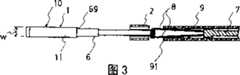
图3是表示图1的夹钳的使用状态的剖面图;Fig. 3 is a cross-sectional view showing the state of use of the clamp of Fig. 1;

图4是表示本例的生物体组织的夹钳装置的前端侧的一部分的立体图;4 is a perspective view showing part of the front end side of the clamping device for living tissue of this example;

图5是表示装载了夹钳的状态的图;Fig. 5 is a diagram showing a state where the tongs are loaded;

图6是表示闭合了夹钳的状态的图;Fig. 6 is a diagram showing a state in which the clamp is closed;

图7是表示拆下了闭合的夹钳的状态的图;Fig. 7 is a diagram showing a state where the closed clamp is removed;

图8是省略了夹钳的描述的夹钳装置的前端侧的剖面图;8 is a cross-sectional view of the front end side of the clamp device with the description of the clamp omitted;

图9是图6的纵向剖面图;Fig. 9 is a longitudinal sectional view of Fig. 6;

图10是表示本例的生物体组织的夹钳装置的变形例的图;FIG. 10 is a diagram showing a modified example of the clamping device for living tissue of this example;

图11是表示第二实施方式的生物体组织的夹钳装置的一部分的立体图;Fig. 11 is a perspective view showing a part of the clamping device for living tissue according to the second embodiment;

图12是表示本例的生物体组织的夹钳装置的一部分的剖面图;Fig. 12 is a sectional view showing part of the clamping device for living tissue of this example;

图13是本例的生物体组织的夹钳装置的分解图;Fig. 13 is an exploded view of the clamping device of the biological tissue of this example;

图14是省略了棒状构件的一部分的放大图;Fig. 14 is an enlarged view omitting a part of the rod-shaped member;

图15是操作金属丝的放大图;Figure 15 is an enlarged view of the operating wire;

图16是从上面看图15的操作金属丝的图;Figure 16 is a view of the operating wire of Figure 15 viewed from above;

图17(A)是表示操作构件和滑动短管的接触关系的图,(B)是沿着(A)的A-A线看到的图;Fig. 17(A) is a diagram showing the contact relationship between the operating member and the short slide tube, and (B) is a diagram seen along the A-A line of (A);

图18(B)是表示本例的作为夹钳装置的构成构件的手柄轴的一部分的主视图,(A)是(B)的左视图;Fig. 18(B) is a front view showing a part of the handle shaft as a constituent member of the clamp device of this example, and (A) is a left side view of (B);

图19(B)是表示本例的作为夹钳装置的构成构件的旋转体的主视图,(A)是(B)的左视图,(C)是(B)的右视图;Fig. 19(B) is a front view showing the rotating body as a constituent member of the tong device of this example, (A) is a left side view of (B), and (C) is a right side view of (B);

图20(B)是本例的作为夹钳装置的构成构件的位置保持机构的主视图,(A)是(B)的左视图;Fig. 20(B) is a front view of the position holding mechanism as a component of the clamp device of this example, and (A) is a left side view of (B);

图21(B)是本例的作为夹钳装置的构成构件的停止机构的主视图,(A)是(B)的左视图;Fig. 21 (B) is the front view of the stop mechanism as the constituent member of the clamp device of this example, (A) is the left side view of (B);

图22是说明本例的夹钳装置的各操作工序的纵向剖面图;Fig. 22 is a longitudinal sectional view illustrating each operation process of the clamp device of this example;

图23是说明旋转体的动作的图;Fig. 23 is a diagram illustrating the action of the rotating body;

图24是第三实施方式的生物体组织的夹钳装置的立体图;Fig. 24 is a perspective view of a clamping device for biological tissue according to a third embodiment;

图25是装载到本例的生物体组织的夹钳装置的装载具的主视图;Fig. 25 is a front view of the loader loaded on the clamp device of the living tissue of this example;

图26是夹钳保持构件的立体图;Figure 26 is a perspective view of a clamp retaining member;

图27是夹钳保持构件的剖面图;Figure 27 is a cross-sectional view of a clamp retaining member;

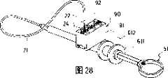
图28是说明本例的生物体组织的夹钳装置的使用方法的图;FIG. 28 is a diagram illustrating a method of using the living tissue clamping device of this example;

图29是表示保持夹钳的状态的图;Fig. 29 is a diagram showing a state in which the clamp is held;

图30是表示将夹钳收纳在外筒管的状态的图;Fig. 30 is a diagram showing a state in which the tongs are housed in the outer tube;

图31是表示从把持构件卸下前端闭合了的夹钳的状态的图;Fig. 31 is a diagram showing a state in which the clamp with the front end closed is detached from the grasping member;

图32是其它夹钳保持构件的立体图;Figure 32 is a perspective view of other clamp retaining components;

图33以及图34是说明其它夹钳保持构件的使用方法的剖面图;33 and 34 are cross-sectional views illustrating how to use other clamp holding members;

图35是以往的夹钳装置的一部分的剖面图;Fig. 35 is a sectional view of a part of a conventional clamp device;

图36是以往的其它夹钳装置的一部分的立体图。Fig. 36 is a perspective view of a part of another conventional clamp device.

具体实施方式Detailed ways

在本发明的生物体组织的夹钳装置(以下简称为“夹钳装置”)以及夹钳中,所谓的前端侧是指在使用状态的生物体组织侧,所谓的基端侧是指与生物体组织的相反侧。参照图1~图3对本发明实施方式的夹钳进行说明。如图1及图2所示,本例的夹钳10包含使细长的金属制板簧在中央部弯曲而得到的夹钳主体1和筒状的夹圈2。夹钳主体1包含,在前端夹持生物体组织的夹持部3、3和显示大致コ字状剖面的基端部4以及在从基端部4延伸出的前端具有自动张开性的两腕部11、11。为了能够进退自由地插入到后述操作构件的内腔,构成夹钳主体的金属制板簧的宽度尺寸w被限制。In the clamp device for living tissue (hereinafter simply referred to as "clamp device") and the clamp of the present invention, the so-called front end side refers to the living body tissue side in use state, and the so-called base end side refers to the biological tissue side. the opposite side of the body tissue. A clamp according to an embodiment of the present invention will be described with reference to FIGS. 1 to 3 . As shown in FIGS. 1 and 2 , thepliers 10 of this example include a pliers main body 1 obtained by bending an elongated metal leaf spring at a central portion, and acylindrical clip ring 2 . The clamp main body 1 includes clampingparts 3 and 3 for clamping living tissue at the front end, abase end part 4 showing a substantially U-shaped cross-section, and two self-expanding parts extending from thebase end part 4 at the front end.Wrist 11, 11. The width dimension w of the metal leaf spring constituting the clamp main body is limited so that it can be freely inserted into the cavity of the operation member described later.

夹钳主体1分别在基端部4具有第一凹部5以及在第一凹部5和夹钳前端部之间具有第二凹部6、6,夹圈2装载于第一凹部5。作为在基端部的第一凹部5的设置部位,优选位于具有把持构件8的前端能够挂在大致コ字状剖面部41上的空间、又不使处于张开状态的夹钳前端的开口变小的位置。另外,作为第二凹部6的设置位置,只要是在第一凹部5和夹钳前端部之间、并且使夹钳前端的夹持部3、3恰好接触的位置,就没有特别的限定。在本例中,通过在第二凹部6的前端侧设置板幅段差69并且通过段差69将基端侧做成凹部,在夹圈2被外力从第一凹部5的装载位置滑动位移时,能够可靠地装载在第二凹部6。虽然夹钳主体的第二凹部6的凹度与第一凹部5相比较大,但从能可靠地完成夹圈2的装载的角度来看是比较理想的。另外,夹钳前端的夹持部3、3使两腕部的前端部向内侧弯曲的同时,在其接触面设置凹凸部,这一点从能够可靠地夹持生物体组织的观点看是理想的。The clamp main body 1 has afirst recess 5 at thebase end 4 andsecond recesses 6 , 6 between thefirst recess 5 and the front end of the clamp, and theclamp ring 2 is mounted on thefirst recess 5 . As the setting position of the firstconcave portion 5 at the base end portion, it is preferably located in a space where the front end of the graspingmember 8 can be hung on the substantiallyU-shaped section 41, without changing the opening of the front end of the clamp in the opened state. small location. In addition, the installation position of the secondconcave portion 6 is not particularly limited as long as it is between the firstconcave portion 5 and the tip of the clamp and the position where the clampingportions 3 and 3 of the tip of the clamp are just in contact. In this example, by providing aplate width step 69 on the front end side of the secondconcave portion 6 and making the base end side a concave portion through thestep difference 69, when theclamp ring 2 is slid and displaced from the loading position of the firstconcave portion 5 by an external force, it can It is reliably loaded on the secondconcave portion 6 . Although the concavity of the secondconcave portion 6 of the clamp body is larger than that of the firstconcave portion 5 , it is ideal from the viewpoint of reliably completing the loading of theclip ring 2 . In addition, it is desirable that the clampingportions 3, 3 at the front end of the clamp bend the front end portions of both arms inwardly, and provide concavo-convex portions on the contact surface. .

夹钳10通常如图1所示,前端的夹持部3打开着,在该状态下,在基端部4的第一凹部5上装载有夹圈2。装载于第一凹部5的夹圈2,因为夹圈2的内腔部分卡在凹下的部分,所以只要没有外力作用就不会自然地前后移动,另外,只要不偏移到前端侧就不会使夹持部3的开口幅度变小。作为夹钳的材质,选用例如不锈钢、钛等。另外,夹钳的腕部的长度,虽然没有特别的限制,但是优选2.0~6.0mm,特别优选3.0~5.0mm。当长度处于上述范围时,夹钳的把持性特别优越。Generally, as shown in FIG. 1 , theclamp 10 has the clampingportion 3 at the front end opened, and theclamp ring 2 is mounted on the firstconcave portion 5 of thebase end portion 4 in this state. Thecollar 2 mounted on thefirst recess 5 does not move back and forth naturally unless there is an external force because the inner cavity of thecollar 2 is caught in the recessed part. The width of the opening of the clampingportion 3 will be reduced. As a material of the clamp, for example, stainless steel, titanium, or the like is selected. In addition, the length of the arm portion of the clamp is not particularly limited, but is preferably 2.0 to 6.0 mm, particularly preferably 3.0 to 5.0 mm. When the length is in the above-mentioned range, the gripping property of the clamp is particularly excellent.

下面,说明用夹钳10夹持生物体组织的方法。首先,将附设在夹钳装置的操作金属丝7前端的具有自动张开性的一对臂状的把持构件8挂在夹钳1的基端部4的大致コ字状剖面部41的内侧。接着,当拉动处于操作构件9的内腔并可前后移动的操作金属丝7时,把持构件8被拉入到操作构件9的内腔且夹圈2碰到操作构件9的前端91。进而,通过拉动操作金属丝7,夹钳主体的两腕部11从夹钳的基端部侧慢慢拉入到夹圈2的内腔,当拉入到第二凹部6的位置时,段差69和夹圈2接触,夹圈2被止住,夹钳主体1的前端的夹持部3、3接触,成为未图示的夹持生物体组织的状态(图2)。接着,当向拉入操作金属丝7的相反方向、即向前方推动时,具有自动张开性的把持构件8从夹钳的基端部4自动地脱出。另一方面,处于闭合状态的夹钳主体1,因为夹圈2可靠地固定在第二凹部6的凹下部分,夹钳主体1与应夹持的生物体组织的大小没有关系,能可靠地夹持住,所以不会立刻脱落,可长期维持夹持生物体组织的状态。Next, a method for clamping living tissue with theclamp 10 will be described. First, a pair of self-expandable arm-shapedholding members 8 attached to the front end of theoperating wire 7 of the clamp device are hung inside the substantiallyU-shaped section 41 of thebase end 4 of the clamp 1 . Then, when theoperating wire 7 that is in the lumen of the operatingmember 9 and can move back and forth is pulled, the holdingmember 8 is pulled into the lumen of the operatingmember 9 and theclamp ring 2 hits thefront end 91 of the operatingmember 9 . Furthermore, by pulling theoperating wire 7, the twoarms 11 of the clamp main body are slowly drawn into the inner cavity of theclamp ring 2 from the base end side of the clamp, and when drawn into the position of thesecond recess 6, thelevel difference 69 is in contact with theclamp ring 2, theclamp ring 2 is stopped, and theclamping parts 3, 3 at the front end of the clamp main body 1 are in contact with each other, and become a state of clamping living tissue not shown in the figure (FIG. 2). Next, when theoperation wire 7 is pushed in the opposite direction to that of pulling in theoperation wire 7 , that is, pushed forward, the graspingmember 8 having self-expandability is automatically disengaged from thebase end portion 4 of the clamp. On the other hand, in the clamp main body 1 in the closed state, because theclip ring 2 is reliably fixed on the concave part of the secondconcave portion 6, the clamp main body 1 has nothing to do with the size of the biological tissue to be clamped, and can reliably It is clamped, so it will not fall off immediately, and the state of clamping biological tissues can be maintained for a long time.

作为夹钳主体1的材质,优选在体腔内、特别在分泌消化酶的胃等中不能被腐蚀的不锈钢以及钛合金等的金属,或者ABS树脂、硬质氯乙烯树脂、聚酰胺、以及聚乙烯等的塑料。另外,从在夹持生物体组织时,从打开夹钳前端的夹持部3的状态到闭合状态,需要长时间保持其闭合状态的观点出发,优选富有弹性的材质。另外,作为夹圈2的材质,并不特别地限制,但是因为和夹钳主体1共同使用,所以可以举出和夹钳主体1相同的材质。具体来说,优选选用氟树脂、聚酰胺、硅树脂等的塑料或者不锈钢、钛合金等的金属。As the material of the clamp main body 1, metals such as stainless steel and titanium alloy that cannot be corroded in the body cavity, especially in the stomach that secretes digestive enzymes, or ABS resin, hard vinyl chloride resin, polyamide, and polyethylene are preferable. etc. plastic. In addition, from the viewpoint of maintaining the closed state for a long time from the state where the grippingportion 3 at the front end of the clamp is opened to the closed state when gripping the living tissue, a material with high elasticity is preferable. In addition, the material of theclamp ring 2 is not particularly limited, but since it is used together with the clamp main body 1, the same material as that of the clamp main body 1 can be used. Specifically, plastics such as fluororesins, polyamides, and silicone resins, or metals such as stainless steel and titanium alloys are preferably used.

根据本实施例的夹钳10,可长期可靠的夹持病灶等的生物体组织。According to theclamp 10 of this embodiment, it is possible to reliably clamp living tissues such as lesions for a long time.

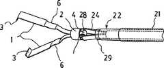
参照图4~图10对本发明的第一实施方式的生物体组织的夹钳装置进行说明。本实施例所述的生物体组织的夹钳装置20具备:外筒管21,其可插入到生物体腔内;操作构件22,其可进退自由地插通到外筒管21内;操作金属丝23,其可进退自由地插通到操作构件22内;把持构件24,其附设在操作金属丝23的前端、通过该操作构件的进退来进行开关且具有自动张开性;自动张开性的夹钳10a,其通过该把持构件的开关可自由装卸地装载在把持构件24的前端并具有夹持生物体组织的夹持部。此外,操作金属丝23的基端部与未图示的手柄连接。A clamping device for living tissue according to a first embodiment of the present invention will be described with reference to FIGS. 4 to 10 . Theclamp device 20 for biological tissue described in this embodiment includes: anouter tube 21, which can be inserted into the cavity of a living body; an operatingmember 22, which can be freely inserted into theouter tube 21; anoperating wire 23, which can be freely inserted into the operatingmember 22; the holdingmember 24, which is attached to the front end of theoperating wire 23, is switched by the advancing and retreating of the operating member and has automatic expansion; the automatic expansion Theclamp 10a is detachably mounted on the front end of the holdingmember 24 by opening and closing of the holding member, and has a holding portion for holding living tissue. Moreover, the base end part of theoperation wire 23 is connected to the handle which is not shown in figure.

在生物体组织的夹钳装置20中,操作构件22的材质,虽然没有特别的限制,但是可以举出聚醚醚酮、聚酰胺、聚酰亚胺等的热可塑性树脂以及薄壁金属线圈。热可塑性树脂从可将操作手柄的动作可靠地传递到前端侧的方面来说是理想的。薄壁金属线圈虽然通过弯曲或拉伸产生间隙,但是从弯曲性和刚性这一点来说是理想的。操作构件22的外径虽然没有特别的限制,但是优选1.7~2.7mm,特别地优选1.9~2.3mm。In theclamping device 20 for living tissue, the material of the operatingmember 22 is not particularly limited, but examples thereof include thermoplastic resins such as polyetheretherketone, polyamide, and polyimide, and thin-walled metal coils. The thermoplastic resin is ideal in that it can reliably transmit the movement of the operating handle to the front end side. A thin-walled metal coil is ideal in terms of bendability and rigidity, although a gap is created by bending or stretching. The outer diameter of theoperation member 22 is not particularly limited, but is preferably 1.7 to 2.7 mm, particularly preferably 1.9 to 2.3 mm.

操作金属丝23将把持构件24固定在前端的同时,具有比金属丝主体的直径稍大并带有段差26的连接部25。另外,从操作构件22的前端到基端侧是操作构件的冲程隔离的位置,在操作构件22的内壁附设操作金属丝主体可插通且与段差26接触的挡块27,防止操作构件22的过量突出的同时,也防止向把持构件24的操作构件22的过量进入。操作金属丝23的材质,虽然没有特别的限制,但是优选其全部或者一部分具有可挠性的材质。具体地,可以举出不锈钢、碳素钢等的金属线、聚酰胺、聚酯、超高分子量聚乙烯等树脂纤维。While theoperating wire 23 fixes the holdingmember 24 at the front end, it has a connectingportion 25 with a step 26 that is slightly larger than the diameter of the wire main body. In addition, from the front end of theoperation member 22 to the base end side is the position where the stroke of the operation member is isolated, and the inner wall of theoperation member 22 is attached with astopper 27 through which the main body of the operation wire can be inserted and which is in contact with the step difference 26, so as to prevent theoperation member 22 from moving. Excessive intrusion into theoperation member 22 of the holdingmember 24 is also prevented while protruding excessively. The material of theoperation wire 23 is not particularly limited, but it is preferable that all or a part thereof has flexibility. Specifically, metal wires such as stainless steel and carbon steel, and resin fibers such as polyamide, polyester, and ultrahigh-molecular-weight polyethylene are mentioned.

外筒管21是中空的长尺状可挠性构件。外筒管21的内径虽然没有特别的限制,但是优选1.8~2.8mm,特别优选2.0~2.4mm。当内径在上述范围内时,操作性特别优越。另外,外筒管21的长度虽然没有特别的限制,但是优选1,500~3,000mm,特别优选1,600~2,300mm。如果长度在上述范围内,在内视镜内的操作性就特别优越。外筒管21的材质,虽然没有特别的限制,但可以举出例如聚四氯乙烯(PTFE)、四氯乙烯-六氟丙烯共聚树脂(FEP)等的氟树脂。Theouter tube 21 is a hollow long flexible member. The inner diameter of theouter tube 21 is not particularly limited, but is preferably 1.8 to 2.8 mm, particularly preferably 2.0 to 2.4 mm. When the inner diameter is within the above range, the workability is particularly excellent. In addition, the length of theouter tube 21 is not particularly limited, but is preferably 1,500 to 3,000 mm, particularly preferably 1,600 to 2,300 mm. When the length is within the above range, the operability in the endoscope is particularly excellent. The material of theouter tube 21 is not particularly limited, but examples thereof include fluororesins such as polytetrachloroethylene (PTFE) and tetrachloroethylene-hexafluoropropylene copolymer resin (FEP).

在生物体组织的夹钳装置20中,作为夹钳10a,虽然只要是如图4所示那样的具备具有自动张开性的两腕部11a和用于闭合两腕部11a的夹持部15的夹圈12的话,就没有特别的限制,但是优选图1以及图2所示的夹钳10。In theclamp device 20 for living tissue, as theclamp 10a, as long as it is equipped with botharm portions 11a with automatic expansion and clamping portions 15 for closing the twoarm portions 11a as shown in FIG. There is no particular limitation on theclamp ring 12, but theclamp 10 shown in FIG. 1 and FIG. 2 is preferred.

根据上述结构,说明向上述生物体组织的夹钳装置20装载夹钳10a的方法。例如,在图4的状态,将操作金属丝23固定在操作手柄,通过拉动操作手柄使操作构件22在操作金属丝23的轴线方向移向把持构件24侧。由此,由一对腕部构成的把持构件24一边与操作构件22的内周面接触,一边因为进入基端侧而徐徐闭合。并且,操作构件22的前端挂钩28被闭合,把持夹钳10a的基端部14来保持夹钳10a。进而,通过拉动操作手柄,夹圈12靠到操作构件22的前端,接着,夹圈12与处于夹钳10a的两腕部中间的段差13接触,夹钳的夹持部15、15闭合(图6、图9)。从该状态,通过将操作构件22返回到原来的位置,把持构件24从操作构件22突出,根据把持构件24具有的自动张开性,一对腕部成为打开的状态,从而能在闭合状态下卸下夹钳10a。Based on the above configuration, a method for loading theclip 10 a on theclip device 20 for living tissue described above will be described. For example, in the state of FIG. 4 , theoperating wire 23 is fixed on the operating handle, and the operatingmember 22 is moved toward the holdingmember 24 in the axial direction of theoperating wire 23 by pulling the operating handle. As a result, the graspingmember 24 composed of a pair of arm portions is gradually closed by entering into the proximal end side while being in contact with the inner peripheral surface of the operatingmember 22 . Then, the front-end hook 28 of theoperation member 22 is closed, and the base end portion 14 of theclamp 10a is held to hold theclamp 10a. And then, by pulling the operating handle, the clampingring 12 leans against the front end of the operatingmember 22, then, the clampingring 12 is in contact with thestep 13 in the middle of the two wrists of theclamp 10a, and the clamping parts 15, 15 of the clamp are closed (Fig. 6. Figure 9). From this state, by returning theoperation member 22 to the original position, thegrip member 24 protrudes from theoperation member 22. According to the automatic expansion property of thegrip member 24, the pair of wrists becomes an open state, so that they can be opened in the closed state. Remove theclamp 10a.

根据生物体组织的夹钳装置20,在夹钳的装载或卸下中,不需要复杂的操作。另外,在用把持构件24保持夹钳10a时,即使操作构件22有多少移动,把持构件24也被收纳在操作构件22的内腔,并且因为前端挂钩28相互重合,夹钳10a不容易落下。另外,即使前端挂钩28间的间隙有多少打开,因为有夹钳10a的基端部4的呈コ字状剖面41的板的宽度,所以夹钳10a也不会从把持构件24落下。According to theclip device 20 for living tissue, complicated operations are not required for loading or unloading clips. In addition, when theclamp 10a is held by the graspingmember 24, even if the operatingmember 22 moves somewhat, the graspingmember 24 is accommodated in the inner cavity of the operatingmember 22, and since the front end hooks 28 overlap each other, theclamp 10a is not easy to drop. In addition, even if the gap between the front end hooks 28 is opened to some extent, theclamp 10a will not fall from the holdingmember 24 because of the plate width of theU-shaped cross section 41 of thebase end portion 4 of theclamp 10a.

在生物体组织的夹钳装置20中,作为把持构件24的形状,并不限定在上述略V字形状,例如,也可以是如图10所示的略U字形状的24a。通过使把持构件24a的腕部弯曲,随着形状变化,能分散加在连接部25的负荷,提高弹簧特性,进而,跟直线状相比,也能使前端部更早地闭合。弯曲的形状,可考虑在两腕部开关动作时,弹簧的特性采用任意的形状。In theclamping device 20 for living tissue, the shape of the graspingmember 24 is not limited to the above-mentioned substantially V-shape, and may be, for example, a substantially U-shape 24a as shown in FIG. 10 . By bending the arm of the grasping member 24a, the load applied to theconnection part 25 can be distributed according to the shape change, the spring characteristic can be improved, and the front end can be closed earlier than the straight one. As for the curved shape, any shape can be adopted in consideration of the characteristics of the spring when both wrists are switched on and off.

另外,作为操作构件22以及操作金属丝23的操作方法,并不限定于上述方法,例如可列举固定操作金属丝23来使操作构件22移动的方法、以及使操作金属丝23以及操作构件22共同移动的方法。In addition, as the operation method of theoperation member 22 and theoperation wire 23, it is not limited to the above method, for example, the method of fixing theoperation wire 23 to move theoperation member 22, and the method of making theoperation wire 23 and theoperation member 22 common method of movement.

根据生物体组织的夹钳装置20,因为在夹钳的装载、卸下等过程中不需要复杂的操作,所以作为使用于明确进行生物体组织的出血部位的结扎、切除等处理的区域用的标记等的生物体组织的夹钳装置非常有用。According to theclamp device 20 for living tissue, since no complicated operations are required in the process of loading and unloading the clamp, it is used as an area for clearly performing ligation, excision, etc. of the bleeding part of the living tissue. It is very useful for clamping device of living tissue such as marking.

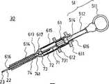
接着,针对第二实施方式的生物体组织的夹钳装置,参照图11~图23进行说明。图12省略了图11的滑动筒状体211的描述。在本例的生物体组织的夹钳装置30中,在与第一实施方式的生物体组织的夹钳装置20相同的结构要素标有相同的符号,并省略了其说明,主要针对不同的点进行说明。即,在生物体组织的夹钳装置30中,与生物体组织的夹钳装置20不同的点在于,还具有控制操作构件的手柄51、设置有使手柄51前进的同时使手柄51的前进停止的第一压入机构、暂时保持手柄51的停止位置的保持机构、使从手柄51的停止位置进一步前进的同时使手柄的前进停止的第二压入机构、手柄51自动地返回到第一压入前的位置的返回机构。即,夹钳装置30具备:外筒管21;以及中空的滑动筒状体211,其和外管筒21在前端侧连接,在基端侧具有连接凸缘213;装置主体部61,其具备前端侧部与滑动筒状体211的内腔配合的主室;停止机构63,其以固定状态装载在装置主体部61的主室内,且位于前端侧;位置保持机构64,其以固定状态装载到在基端侧与停止机构63接触的主室内;手柄51,其从基端侧插入到装置主体部61内;棒状构件71,其基端侧的一端接触到旋转体65的基板651的里面,另一端从装置主体部61的前端侧突出。Next, a clamping device for living tissue according to a second embodiment will be described with reference to FIGS. 11 to 23 . FIG. 12 omits the description of the sliding cylinder 211 of FIG. 11 . In the livingtissue clamping device 30 of this example, the same components as those in the livingtissue clamping device 20 of the first embodiment are denoted by the same reference numerals, and descriptions thereof are omitted, and differences are mainly focused on. Be explained. That is, the clampingdevice 30 for living tissue differs from the clampingdevice 20 for living tissue in that it further includes ahandle 51 for controlling the operating member, and a device for stopping the advance of thehandle 51 while advancing thehandle 51 is provided. The first push-in mechanism, the holding mechanism that temporarily holds the stop position of thehandle 51, the second push-in mechanism that stops the advancement of the handle while further advancing from the stop position of thehandle 51, and thehandle 51 automatically returns to the first push-in mechanism. Return mechanism to the position before entering. That is, theclamp device 30 is provided with: anouter tube 21; and a hollow sliding cylindrical body 211 connected to theouter tube 21 at the front end side and having a connecting flange 213 at the base end; The main chamber in which the front end side is matched with the inner cavity of the sliding cylindrical body 211; thestop mechanism 63, which is mounted in the main chamber of the devicemain body 61 in a fixed state, and is located on the front end side; theposition holding mechanism 64, which is mounted in a fixed state To the main chamber that is in contact with thestop mechanism 63 at the base end side; thehandle 51 is inserted into the devicemain body 61 from the base end side; , and the other end protrudes from the front end side of the devicemain body 61 .

手柄51包含环状的把持部511和一端与把持部511连接、另一端具备王冠状的第一凸轮部514的手柄轴512。把持部511是手术者用手把持操作的,具有手术者的手指可插入的空间。第一凸轮部514是在圆筒构件的端面上每隔60度形成谷部的具有6个三角状突起的环状突起。第一凸轮部514与在停止机构63内以及位置保持机构64内移动的旋转体65的3个卡止叶片653配合并将手柄的前进力以及旋转力加给旋转体65。此外,附图作图上存在环状的把持部511和手柄轴512的连接部周围的形态不同的地方。Thehandle 51 includes anannular grip portion 511 and ahandle shaft 512 that is connected to thegrip portion 511 at one end and has a crown-shapedfirst cam portion 514 at the other end. Thegrip part 511 is gripped and operated by the operator's hand, and has a space into which the operator's fingers can be inserted. Thefirst cam portion 514 is an annular protrusion having six triangular protrusions that form valleys at intervals of 60 degrees on the end surface of the cylindrical member. Thefirst cam portion 514 cooperates with the three locking blades 653 of therotating body 65 moving in thestop mechanism 63 and theposition holding mechanism 64 to apply the forward force and the rotating force of the handle to therotating body 65 . In addition, there is a difference in the form around the connecting portion of the ring-shapedgrip portion 511 and thehandle shaft 512 in the drawings.

位置保持机构64是固定在装置主体部61的主室内615的圆筒构件,其在操作前的状态中决定旋转体65的收纳位置,通过第一压入操作,引导旋转体65前进的同时,将旋转体诱导至第二压入的开始位置。在内周面644沿着长度方向形成有配合旋转体65的3个板状的叶片构件653的3个配合槽641。另外,在前端侧开口的圆周边缘附设有具备6个锯齿剖面形状的缺口部645的凸轮槽642。当旋转体的叶片构件653的前端通过弹性加载接触到缺口部645的斜面时,凸轮槽642给与最大60度的旋转。缺口部645的斜面从前端侧看是在逆时针方向向下倾斜地形成的。Theposition holding mechanism 64 is a cylindrical member fixed in themain chamber 615 of the devicemain body 61, and determines the storage position of therotating body 65 in the state before operation, and guides the rotatingbody 65 to move forward through the first push-in operation. The rotary body is induced to the starting position of the second press-in. Three engaging grooves 641 for engaging the three plate-shaped blade members 653 of therotating body 65 are formed along the longitudinal direction on the inner peripheral surface 644 . In addition, a cam groove 642 having six notches 645 having a zigzag cross-sectional shape is attached to the peripheral edge of the opening on the front end side. When the front end of the blade member 653 of the rotating body contacts the slope of the notch portion 645 by elastic loading, the cam groove 642 gives a maximum 60-degree rotation. The slope of the notch 645 is formed to be inclined downward in the counterclockwise direction when viewed from the front end side.

停止机构63是在装置主体部61的主室内接触在位置保持机构64的前端侧而被固定的圆筒构件,通过第一压入操作使进入的旋状体65停止的同时,通过第二压入操作引导旋转体65的进入。停止机构63具有在内周面从前端侧延伸到轴方向的中途(图22中,符号m的长度)的3个肋631。3个肋631以120度为间隔且一个肋条从前端侧看,形成在相对于铅直轴逆时针旋转50度的位置。此外,停止机构63在设置于装置主体部61的主室内的状态下,前端开口接触到主室的壁。因此,旋转体65并不会从停止机构63向前端方向突出。停止机构63的长度1是旋转体65的前进行程。Thestop mechanism 63 is a cylindrical member fixed by contacting the front end side of theposition holding mechanism 64 in the main chamber of the devicemain body 61, and stops the enteringspiral body 65 by the first push-in operation, and at the same time by the second push-in operation. The entry operation guides the entry of therotating body 65. Thestop mechanism 63 has threeribs 631 extending from the front end side to the middle of the axial direction (in FIG. Formed at a position rotated 50 degrees counterclockwise with respect to the vertical axis. In addition, when thestop mechanism 63 is installed in the main chamber of the devicemain body 61 , the front end opening contacts the wall of the main chamber. Therefore, the rotatingbody 65 does not protrude toward the front end from thestopper mechanism 63 . The length 1 of thestop mechanism 63 is the forward stroke of therotating body 65 .

旋转体65与手柄轴前端的第一凸轮部514配合,使位置保持机构64以及停止机构63内前进、后退或者旋转,来对棒状构件71传递操作力。旋转体65具有缺口部654以120度为间距位于前端侧的基板651,以及在基板651上在轴方向延伸的同时在缺口部654之间以120度间距附设的板状的叶片构件653中,其基端侧的一端为尖形剖面形状的第二凸轮部654。另外,在基板651的里面中央具有配合棒状构件71的前端部731的配合孔655。The rotatingbody 65 cooperates with thefirst cam portion 514 at the front end of the handle shaft to move theposition holding mechanism 64 and thestop mechanism 63 forward, backward, or rotate to transmit the operating force to the rod-shapedmember 71 . The rotatingbody 65 has a base plate 651 with notches 654 at a pitch of 120 degrees on the front end side, and a plate-shaped blade member 653 provided between the notches 654 at a pitch of 120 degrees while extending in the axial direction on the base plate 651 , One end on the proximal side is a second cam portion 654 having a pointed cross-sectional shape. In addition, a fitting hole 655 for fitting thefront end portion 731 of the rod-shapedmember 71 is provided at the center of the back surface of the base plate 651 .

棒状构件71具备:操作金属丝23,其在前端附设把持构件24、基端被固定在固定环部73;操作构件22,在其内腔插通操作金属丝23、在基板侧具有细调节部741;滑动短管75,在基端侧与细调节部741接触的筒状管外周面上形成窗部751。滑动短管75的基端部751与旋转体的基板651里面的配合孔655配合。固定环部73固定在比装置主体部61的主室稍微前端侧,不与手柄的操作连动。在滑动短管75的窗部751,可自由滑移地嵌合有操作金属丝23的固定环部73。操作构件22通过旋转体65的前进(手柄51的前进),经由滑动短管75抵抗弹簧74的弹性加载前进,当通过弹簧74的弹性加载旋转体65后退时就会与此连动而后退。另外,操作金属丝23可进退自由地插入到操作构件22内,基端侧的连接部733在滑动短管75的窗部751内滑移,所以不与手柄51的操作(操作构件22的动作)连动。The rod-shapedmember 71 is equipped with: anoperation wire 23, which is attached with a grippingmember 24 at the front end, and whose base end is fixed to the fixedring portion 73; 741 : slide theshort tube 75, and form awindow portion 751 on the outer peripheral surface of the cylindrical tube in contact with thefine adjustment portion 741 at the base end side. Thebase end portion 751 of theshort slide tube 75 fits into the fitting hole 655 inside the base plate 651 of the rotating body. The fixedring portion 73 is fixed slightly on the front end side of the main chamber of the devicemain body portion 61, and is not linked to the operation of the handle. The fixedring portion 73 of theoperating wire 23 is fitted in thewindow portion 751 of theshort slide tube 75 so as to be slidable. The operatingmember 22 advances through the advancement of the rotating body 65 (advancement of the handle 51), and advances against the elastic loading of thespring 74 via the short slidingtube 75. When the elastic loading of thespring 74, the rotatingbody 65 moves backward in conjunction with this. In addition, theoperation wire 23 can be freely inserted into theoperation member 22, and theconnection portion 733 on the base end side slides in thewindow portion 751 of theshort slide tube 75, so it is not related to the operation of the handle 51 (the operation of the operation member 22). )Gearing.

在装置主体部61的内部具有从前端侧顺次出入操作构件22的前端开口616、收纳弹簧74的室614、固定棒状构件的固定环部73的固定部617、收纳停止机构63和位置保持机构64的主室615、插入手柄轴的前端的插入口616。装置主体部61在筒状体从基端侧开始附设第一凸缘部611、第二凸缘部612来提高操作性。The inside of the devicemain body 61 has a front end opening 616 through which theoperation member 22 is inserted and withdrawn in order from the front end side, achamber 614 for accommodating thespring 74, a fixingpart 617 for fixing the fixingring part 73 of the rod-shaped member, thestorage stop mechanism 63, and the position holding mechanism. Themain chamber 615 of 64 is inserted into theinsertion port 616 at the front end of the handle shaft. The devicemain body 61 is provided with afirst flange portion 611 and asecond flange portion 612 on the cylindrical body from the base end side to improve operability.

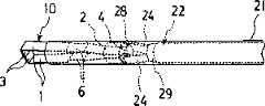
滑动筒状体211是操作中空外筒管21的进退的构件,是嵌入到装置主体部61前端部的筒状物。前端侧与插入到生物体腔内的中空外筒管21连接,在基端侧具备具有与装置主体部的凹部613配合的凸部(未图示)的固定凸缘213。在固定凸缘213附设有解除滑动筒状体211与装置主体部61的配合的配合解除机构214。操作构件22插入到外筒管21。并且,装载于装置主体部61的滑动筒状体211,在解除与装置主体部61之间的配合的状态下,如果拉手柄51或者进行滑动筒状体211的压入操作,则外筒管21就相对于操作构件22前进。由此,夹钳10a的两腕部闭合,在闭合夹钳10a的状态下,可暂时性的收纳在外筒管21内。由此,在将外筒管21插入到内视镜时,因为夹钳10a被收纳在外筒管21内,所以不损伤内视镜的钳子孔。The sliding cylindrical body 211 is a member for operating the forward and backward movement of the hollow outercylindrical tube 21 , and is a cylindrical body fitted into the front end of the devicemain body 61 . The distal end is connected to the hollowouter tube 21 inserted into the living body cavity, and the proximal end is provided with a fixing flange 213 having a convex portion (not shown) that fits into theconcave portion 613 of the device main body. Attached to the fixing flange 213 is an engagement release mechanism 214 for releasing the engagement between the sliding cylindrical body 211 and the devicemain body 61 . The operatingmember 22 is inserted into theouter tube 21 . And, when the sliding cylindrical body 211 mounted on the devicemain body 61 is released from the engagement with the devicemain body 61, if thehandle 51 is pulled or the sliding cylindrical body 211 is pushed in, the outer tube will 21 is advanced relative to the operatingmember 22. As a result, both arms of theclamp 10a are closed, and theclamp 10a can be temporarily stored in theouter tube 21 in the closed state. Thereby, when theouter tube 21 is inserted into the endoscope, since theclamp 10a is accommodated in theouter tube 21, the forceps hole of the endoscope is not damaged.

下面,主要参照图22以及图23对第二实施方式的夹钳装置30的操作方法进行以下说明。夹钳装置30的操作方法包含第一压入操作、保持工序、第二压入操作以及返回工序。在第一压入操作中,当压入手柄51时,手柄前端的第一凸轮部514和旋转体65的第二凸轮部654接触(图22(a)以及图23(a))。此时,第一凸轮部514和第二凸轮部654的相互的凸轮部的山状顶部稍微错位地配置着。因此,手柄前端的第一凸轮部514的山状的顶部515一边与旋转体的第二凸轮部654的山状的倾斜面接触,一边前进。并且,旋转体65从位置保持机构64向停止机构内63移动。当旋转体65进入停止机构63内时,第一凸轮部514和第二凸轮部654完全啮合,旋转体65从初始位置逆时针旋转30度(第一次旋转)。在该状态中,因为是旋转体的基板651与停止机构63的肋631接触的关系,所以旋转体65只移动行程n,碰到肋631的端面而停止(图22(b)以及图23(b))。通过第一压入操作,与旋转体65的移动连动的棒状构件71的操作构件22前进,把持构件24拉入到操作构件22内,闭合把持构件24的前端,在把持构件24保持夹钳10a(图5)。Next, the operation method of theclamp device 30 according to the second embodiment will be described below mainly with reference to FIGS. 22 and 23 . The operation method of theclamp device 30 includes a first pushing operation, a holding step, a second pushing operation, and a returning step. In the first pushing operation, when thehandle 51 is pushed in, thefirst cam portion 514 at the front end of the handle contacts the second cam portion 654 of the rotating body 65 ( FIG. 22( a ) and FIG. 23( a )). At this time, the mountain tops of the cam portions of thefirst cam portion 514 and the second cam portion 654 are slightly shifted from each other. Therefore, the mountain-shaped top 515 of thefirst cam portion 514 at the front end of the handle moves forward while contacting the mountain-shaped inclined surface of the second cam portion 654 of the rotating body. Then, the rotatingbody 65 moves from theposition holding mechanism 64 to the inside of thestop mechanism 63 . When therotating body 65 enters thestop mechanism 63, thefirst cam portion 514 and the second cam portion 654 are fully engaged, and therotating body 65 rotates 30 degrees counterclockwise from the initial position (the first rotation). In this state, because the base plate 651 of the rotating body is in contact with therib 631 of thestop mechanism 63, the rotatingbody 65 only moves by stroke n, and stops when it hits the end surface of the rib 631 (Fig. 22(b) and Fig. 23( b)). By the first push-in operation, the operatingmember 22 of the rod-shapedmember 71 moved forward in conjunction with the movement of therotating body 65, the holdingmember 24 is drawn into the operatingmember 22, the front end of the holdingmember 24 is closed, and the clamp is held on the holdingmember 24. 10a (Fig. 5).

在保持工序中,第一压入操作后,当从手柄51拿开手时,利用弹簧74的反弹力旋转体65后退,旋转体65的第二凸轮部和位置保持机构的凸轮槽642配合。此时,旋转体65的第二凸轮部的前端沿着锯齿状的凸轮槽642的倾斜面从初始位置逆时针旋转60度(第二次旋转)并在凸轮槽642的谷部停止(图22(c)以及图23(c))。由此,可维持将张开的夹钳10a保持在把持构件24前端的状态。另外,因为夹钳10a的开度一定,所以不需要做由细微的手柄操作的位置调整。In the holding process, when the hand is removed from thehandle 51 after the first push-in operation, the rotatingbody 65 retreats due to the rebound force of thespring 74, and the second cam portion of therotating body 65 engages with the cam groove 642 of the position holding mechanism. At this time, the front end of the second cam portion of therotating body 65 rotates 60 degrees counterclockwise from the initial position along the inclined surface of the serrated cam groove 642 (the second rotation) and stops at the valley portion of the cam groove 642 (Fig. 22 (c) and Figure 23(c)). Thereby, the state where the openedclamp 10a is held at the front end of the graspingmember 24 can be maintained. In addition, since the opening degree of theclamp 10a is constant, it is not necessary to perform position adjustment by fine handle operation.

在第二压入操作中,当从保持状态按手柄时,手柄轴的第一凸轮部514和旋转体的第二凸轮部配合,进而旋转体65从初始位置旋转90度(第三次旋转)。在该状态下,旋转体65的缺口部654和停止机构63的肋631处于配合的位置关系。在该状态下,压入手柄51,旋转体65前进到停止机构63的前端(图22(d)以及图23(d))。通过第二压入操作,与旋转体65的移动连动的棒状构件71的操作构件22又前进行程m,关闭夹钳10a的夹持部15(图6)。In the second push-in operation, when the handle is pressed from the holding state, thefirst cam portion 514 of the handle shaft is engaged with the second cam portion of the rotating body, so that the rotatingbody 65 rotates 90 degrees from the initial position (the third rotation) . In this state, the notch portion 654 of therotating body 65 and therib 631 of thestop mechanism 63 are in a positional relationship that engages with each other. In this state, thehandle 51 is pushed in, and therotating body 65 advances to the front end of the stop mechanism 63 ( FIG. 22( d ) and FIG. 23( d )). By the second push-in operation, the operatingmember 22 of the bar-shapedmember 71 in conjunction with the movement of therotating body 65 advances further by stroke m, and closes the clamping portion 15 of theclamp 10a ( FIG. 6 ).

在返回工序中,第二压入操作后,当从手柄51拿开手时,利用弹簧74的反弹作用,操作构件22返回,与此连动,解除旋转体65、叶片构件653和停止机构63的肋631的配合,旋转体65的前端碰上螺旋状的凸轮槽642,进而沿着其倾斜面,在谷部停止,从初始位置逆时针旋转120度(第四次旋转)。在该状态中,成为旋转体65的叶片构件653和位置保持机构64的槽641配合的位置。因此,旋转体65自动返回到初始的位置。通过返回工序,因为操作构件22返回到原来的位置,所以具有自动张开性的把持构件的前端张开,夹钳10a从把持构件24脱落。另一方面,夹钳10a的前端闭合,结束向生物体组织的夹钳10a的装载。In the return process, after the second push-in operation, when the hand is removed from thehandle 51, the operatingmember 22 is returned by the rebound action of thespring 74, and in conjunction with this, the rotatingbody 65, the blade member 653 and thestop mechanism 63 are released. With the cooperation of therib 631, the front end of therotating body 65 hits the helical cam groove 642, and then stops at the valley along its inclined surface, and rotates 120 degrees counterclockwise from the initial position (the fourth rotation). In this state, the blade member 653 of therotating body 65 is engaged with the groove 641 of theposition holding mechanism 64 . Therefore, the rotatingbody 65 automatically returns to the original position. In the return step, since theoperation member 22 returns to the original position, the front end of the grasping member having self-expandability is opened, and theclip 10a is detached from the graspingmember 24 . On the other hand, the front end of theclip 10a is closed, and loading of theclip 10a on the living tissue is completed.

在第二实施方式的夹钳装置30中,操作方法并不限定于上述那样相对性地看固定操作金属丝23而使操作构件22移动的方法。例如通过使弹簧的位置、旋转体、停止机构、位置保持机构的方向相反,也能固定操作构件而使操作金属丝移动。另外,通过改变旋转体、停止机构、位置保持机构的形状,也能进行多阶段的停止、位置保持。In theclamp device 30 of the second embodiment, the operation method is not limited to the method of moving theoperation member 22 by fixing theoperation wire 23 as described above. For example, by reversing the position of the spring, the direction of the rotating body, the stop mechanism, and the position holding mechanism, the operation member can be fixed to move the operation wire. In addition, by changing the shape of the rotating body, the stop mechanism, and the position holding mechanism, multi-stage stopping and position holding can also be performed.

根据第二实施方式的夹钳装置30,在进行经内视镜的生物体组织的出血部位的结扎或切除等时,不需要用内视镜观察夹钳张开的情况,因为不需要做通过细微的手柄操作进行位置调整,所以能谋求缩短处理时间。另外,通过在手柄标有已决定移动距离的停止位置,可使内视镜处理具的前端按规定量出入。According to theclamp device 30 of the second embodiment, when performing endoscopic ligation or excision of the bleeding part of the living tissue, it is not necessary to observe the opening of the clamp with the endoscope, because there is no need to pass through the clamp. The position is adjusted by fine handle operation, so the processing time can be shortened. In addition, by marking the stop position with a determined moving distance on the handle, the front end of the endoscope treatment tool can be moved in and out by a predetermined amount.

下面,参照图24~图31对第三实施方式的夹钳装置进行说明。在第三实施方式的夹钳装置40中,与第二实施方式的夹钳装置30相同的结构要素标有相同的符号并省略了其说明,主要针对不同点进行说明。即,夹钳装置40与夹钳装置30的不同点是在第二凸缘612附近的装置主体部61的外周面附设了夹钳保持构件90。夹钳保持构件90是方块体91,在收纳槽92的直角方向具有3个由将夹钳10的前端向下并在没入状态收纳的夹钳收纳槽92和通过收纳槽92的中心并直行的导轨槽93构成的大致十字槽94。另外,在方块体91的里面形成有和装载工具80配合的配合槽94。通过闭合配合槽94的一端作为壁,从而容易定位。即,当装载工具的板状卡止片81完全与配合槽94配合时,使得夹钳保持构件90大致处于装置主体部61的中央。Next, a clamp device according to a third embodiment will be described with reference to FIGS. 24 to 31 . In the clamp device 40 of the third embodiment, the same reference numerals are assigned to the same constituent elements as those of theclamp device 30 of the second embodiment, and description thereof will be omitted, and the difference will be mainly described. That is, the difference between the clip device 40 and theclip device 30 is that theclip holding member 90 is attached to the outer peripheral surface of the devicemain body 61 in the vicinity of thesecond flange 612 . Theclamp holding member 90 is ablock body 91, and has threeclamp storage slots 92 in the direction perpendicular to thestorage slots 92, which are stored in a submerged state with the front end of theclamp 10 downward, and a straight line through the center of thestorage slot 92. Therail groove 93 constitutes a substantiallycross groove 94 . In addition, afitting groove 94 fitting with theloading tool 80 is formed in the inner side of theblock body 91 . Positioning is facilitated by closing one end of thefitting groove 94 as a wall. That is, when the plate-shapedlocking piece 81 of the loading tool is completely engaged with the engaginggroove 94 , theclamp holding member 90 is positioned approximately at the center of the devicemain body 61 .

夹钳收纳槽92的槽宽度比两腕部11的板宽幅稍大并且从最深部向表面宽度稍宽。夹钳收纳槽92的深度是在收纳夹钳10的状态下能稍稍看得见基端部的程度的深度,另外,夹钳收纳槽92的槽长度比夹钳10在自然状态张开的宽度稍小。由此,在将夹钳10收纳在收纳槽92时,因为使得两腕部稍微闭合那样地进入,所以能稳定地收纳。导轨槽93的形状虽然没有特别的限制,但是在本例中,通过做成平面视图呈箭头形状的槽,把持构件24的前端挂钩28容易引导至夹钳的基端部的大致コ字形状部41。优选导轨槽93用发光涂料着色,以便在较暗的内视镜室中也能识别导轨槽93。作为形成在结构体91的夹钳收纳槽92的数量,除了上述3个外可以是1个、2个、或者4个以上。夹钳保持构件90的材质,虽然没有特别的限制,但是当使用透明的材料时,从外部能观察夹钳10是否被收纳这一点来说是好的。透明的材料,可以选取丙烯腈·丁二烯·苯乙烯树脂(ABS树脂)、聚乙烯、聚苯乙烯、聚碳酸酯、丙烯树脂等的树脂材料。另外,夹钳保持构件90,在将夹钳10收纳在收纳槽92的状态,被收纳在未图示的灭菌袋,从不需要每次进行灭菌处理,操作性上好这方面来说是理想的。The groove width of theclamp storage groove 92 is slightly larger than the plate width of botharm portions 11 and is slightly wider from the deepest portion toward the surface. The depth of theclamp storage groove 92 is such that the base end can be seen slightly in the state where theclamp 10 is stored, and the groove length of theclamp storage groove 92 is longer than the width of theclamp 10 in a natural state. slightly smaller. Thereby, when storing thepliers 10 in thestorage groove 92, since both arms are inserted so as to be slightly closed, it can be stored stably. The shape of therail groove 93 is not particularly limited, but in this example, by making it an arrow-shaped groove in plan view, thefront end hook 28 of the holdingmember 24 can be easily guided to the substantially U-shaped portion of the base end portion of the clamp. 41. Therail groove 93 is preferably colored with luminescent paint, so that therail groove 93 can also be recognized in a darker endoscope room. As the number ofclip storage grooves 92 formed in thestructure body 91, one, two, or four or more may be used other than the above-mentioned three. The material of theclip holding member 90 is not particularly limited, but it is preferable to use a transparent material so that whether or not theclip 10 is housed can be observed from the outside. As the transparent material, resin materials such as acrylonitrile butadiene styrene resin (ABS resin), polyethylene, polystyrene, polycarbonate, and acrylic resin can be selected. In addition, theclip holding member 90 is stored in a sterilization bag (not shown) in the state where theclip 10 is stored in thestorage groove 92, and it is never necessary to perform sterilization treatment every time, and the operability is good. is ideal.

装载工具80是用于在装置主体部61的筒状体安装夹钳保持构件90的适配器。装载工具80由装载于装置主体部61的环部82和具有附设在环部82上方的凸缘部82且与夹钳保持构件90的配合槽94配合的板状的卡止片81构成。Theloading tool 80 is an adapter for attaching theclip holding member 90 to the cylindrical body of the devicemain body 61 . Theloading tool 80 is composed of aring portion 82 mounted on the devicemain body portion 61 and a plate-shapedlocking piece 81 having aflange portion 82 attached above thering portion 82 and engaging with afitting groove 94 of theclamp holding member 90 .

下面,参照图28~图31对使用夹钳装置40来止血的方法进行说明。在图28中,滑动筒状体211的凸缘213省略描述。首先,在将夹钳10收纳在收纳槽92的状态下,从灭菌袋取出夹钳保持构件90,固定在装置主体部61。一边用手拿外筒管21的前端部分,一边将把持构件24的前端推到夹钳保持构件90的导轨槽93上。此时,因为手不能直接接触夹钳10,所以不用担心污染。Next, a method of hemostasis using the clip device 40 will be described with reference to FIGS. 28 to 31 . In FIG. 28 , the description of the flange 213 of the sliding cylindrical body 211 is omitted. First, with theclip 10 stored in thestorage groove 92 , theclip holding member 90 is taken out from the sterilization bag and fixed to the devicemain body 61 . While holding the front end portion of the outercylindrical tube 21 by hand, the front end of the holdingmember 24 is pushed onto therail groove 93 of theclamp holding member 90 . At this time, since hands cannot directly touch theclamp 10, there is no fear of contamination.

下面,当压入手柄51进行第一压入操作时,操作构件22前进,附设在操作金属丝23前端的把持构件24的前端闭合,保持夹钳10的基端部4(图28、图29)。该操作只要用一只手握住手柄51,用另一只手握住外筒管21就可以,可简单的操作。另外,通过将把持构件24的前端压入到导轨槽93这样简单的操作就可在把持构件24上安装夹钳10。此外,在操作构件22的前端侧附设与夹圈2接触的环部29。环部29的外径和夹圈2的外径几乎相同,能通过操作构件22的前进来使夹圈2前进。Next, when the push-inhandle 51 performs the first push-in operation, the operatingmember 22 advances, and the front end of the holdingmember 24 attached to the front end of theoperating wire 23 is closed to keep thebase end portion 4 of the clamp 10 (Fig. 28, Fig. 29 ). This operation only needs to hold thehandle 51 with one hand, and hold theouter tube 21 with the other hand, which can be easily operated. In addition, theclamp 10 can be attached to the holdingmember 24 by a simple operation such as pressing the front end of the holdingmember 24 into therail groove 93 . In addition, aring portion 29 in contact with theclamp ring 2 is attached to the front end side of theoperation member 22 . The outer diameter of thering portion 29 is substantially the same as that of theclamp ring 2 , and theclamp ring 2 can be advanced by advancing theoperation member 22 .

在该状态下,解除装置主体部61和滑动筒状体211的配合,将手柄51拉到基端侧。由此,操作构件22相对外筒管21被拉到基端侧,夹钳10以闭合前端的状态暂时收纳在外筒管21内(图30)。在该状态,将外筒管21通过未图示的内视镜中,将内视镜整体插入到生物体内的出血部位的附近。并且,一边确认内视镜,一边从内视镜的前端使外筒管21外伸。接着,当将手柄51压入到前端侧时,因为操作构件22相对于外筒管21前进,所以夹钳10从外筒管21外伸,并且前端处于张开的状态。接着,将前端张开的夹钳10推至目的部位。并且,当进一步压入手柄51进行第二压入操作时,操作构件22前进,将夹钳的夹圈2推到前端侧。由此,夹圈2与夹钳10的第二凹部6配合,闭合前端并夹持生物体的目的部位。因为由操作构件22被推出的夹圈2与第二凹部6配合,所以能维持夹钳闭合的状态。闭合夹钳10后,当从手柄51拿开手时,通过返回机构,手柄51回到原来的位置。此时,因为操作构件22也后退,所以把持构件24打开,能将闭合的夹钳10从把持构件24卸下(图31)。并且,将夹钳10留置在体内,将把持构件24与内视镜同时从体内拿出。当用夹钳10把持的部位坏死时,夹钳10自然的脱落并从体内排出。In this state, the engagement between the devicemain body 61 and the sliding cylindrical body 211 is released, and thehandle 51 is pulled to the proximal end side. As a result, theoperation member 22 is pulled toward the base end side with respect to theouter tube 21, and theclip 10 is temporarily accommodated in theouter tube 21 with the distal end closed ( FIG. 30 ). In this state, the outercylindrical tube 21 is passed through an endoscope not shown, and the entire endoscope is inserted into the vicinity of the bleeding site in the living body. Then, while confirming the endoscope, the outercylindrical tube 21 is extended from the front end of the endoscope. Next, when thehandle 51 is pushed into the front end side, since theoperation member 22 advances relative to theouter tube 21 , thepliers 10 protrude from theouter tube 21 , and the tip is opened. Next, push theclamp 10 with its front end opened to the target site. Then, when thehandle 51 is further pushed in to perform the second pushing operation, theoperation member 22 advances, and theclamp ring 2 of the pliers is pushed to the front end side. Thus, theclamp ring 2 cooperates with thesecond recess 6 of theclamp 10 to close the front end and clamp the target part of the living body. Since theclamp ring 2 pushed out by theoperation member 22 is engaged with the secondconcave portion 6, the closed state of the clamp can be maintained. After closing theclamp 10, when the hand is taken away from thehandle 51, thehandle 51 returns to the original position through the return mechanism. At this time, since theoperation member 22 also retreats, the holdingmember 24 is opened, and theclosed clamp 10 can be detached from the holding member 24 ( FIG. 31 ). Then, theclamp 10 is left in the body, and the holdingmember 24 is taken out of the body at the same time as the endoscope. When the part grasped by theclip 10 is necrotic, theclip 10 will fall off naturally and be discharged from the body.

下面,参照图32~图34对夹钳保持构件90的变形例进行说明。在夹钳保持构件90a中,与夹钳保持构件90相同的结构要素标有相同的符号并省略了其说明,主要针对不同的点进行说明。即,在夹钳保持构件90a中,和夹钳保持构件90不同的点是:做1个大致十字槽;将导轨槽93a做成通过收纳槽的中心直行并朝向中心下降倾斜,在导轨槽中心部的深度做成在收纳夹钳10的状态中处在夹圈2的上方且该把持构件搭在被收纳的该夹钳的大致コ字状的基端部的深度;还有,不是向着装置主体部61的外周面装载,而与夹钳装置做成另外的构件。作为导轨槽93的形式,除了选取在平面视图为上述箭头形状、矩形形状以外,还有扇形形状等。Next, modifications of theclip holding member 90 will be described with reference to FIGS. 32 to 34 . In theclip holding member 90a, the same components as those of theclip holding member 90 are denoted by the same reference numerals and their descriptions are omitted, and the different points will be mainly described. That is, in theclamp holding member 90a, the points different from theclamp holding member 90 are: a substantially cross groove is made; theguide rail groove 93a is made to go straight through the center of the storage groove and slope downward toward the center, and the center of the guide rail groove The depth of the portion is made to be above theclamp ring 2 in the state of accommodating theclamp 10 and the depth of the base end portion of the substantially U-shaped portion of the clamp that the gripping member is placed on; in addition, it is not toward the device The outer peripheral surface of themain body portion 61 is mounted, and is made as a separate member from the clamp device. As the form of theguide rail groove 93, in addition to the above-mentioned arrow shape and rectangular shape in plan view, there is also a sector shape and the like.

接着,对取出收纳在夹钳保持构件90a的夹钳10的方法进行说明。此外,图33是图32的剖面图,图34是表示在图33中把持构件24闭合状态的图。将把持构件24的前端推到装载夹钳10的夹钳保持构件90a的导轨槽93a上。在该状态下,通过使操作构件22移向夹钳保持构件90a侧,维持由保持构件24保持夹钳10的状态(图34)。接着,将夹钳10从夹钳保持构件90a卸下,完成向夹钳10的夹钳装置的装载。Next, a method of taking out theclip 10 stored in theclip holding member 90a will be described. In addition, FIG. 33 is a sectional view of FIG. 32 , and FIG. 34 is a diagram showing a closed state of the holdingmember 24 in FIG. 33 . The front end of the holdingmember 24 is pushed onto therail groove 93 a of theclamp holding member 90 a of theloading clamp 10 . In this state, by moving the operatingmember 22 to the side of theclip holding member 90a, the state in which theclip 10 is held by the holdingmember 24 is maintained ( FIG. 34 ). Next, thetongs 10 are detached from thetongs holding member 90a, and the loading of the tongs device to thetongs 10 is completed.

根据第三实施方式的夹钳装置40,除了起到和第二实施方式的夹钳装置30同样的操作之外,用一只手握住手柄51,用另一只手握住外筒管21,用将把持构件24的前端压入到导轨槽93这种简单的操作就可将夹钳10安装到把持构件24上。因此,即使不习惯于该操作的操作者也能简单并且效率较高地进行夹钳装载操作。According to the clamp device 40 of the third embodiment, in addition to performing the same operation as that of theclamp device 30 of the second embodiment, thehandle 51 is held with one hand, and theouter tube 21 is held with the other hand. Theclamp 10 can be mounted on the holdingmember 24 by a simple operation of pressing the front end of the holdingmember 24 into theguide rail groove 93 . Therefore, even an operator who is not accustomed to this operation can easily and efficiently perform the tong loading operation.

产业上的可利用性Industrial availability

本发明的夹钳以及夹钳装置作为使用于通过内视镜进行生物体组织的出血部位的结扎、裂创的缝合以及粘膜组织切除时的标记等的处理工具非常有用。The clip and the clip device of the present invention are very useful as treatment tools for ligation of bleeding parts of living tissue, suturing of lacerations, and marking of mucosal tissue excision using an endoscope.

Claims (22)

9. the gripping mechanism of bio-tissue as claimed in claim 7 is characterized in that, possesses: Handle axis, and whole advance and retreat of itself and above-mentioned handle and front end possess first cam part; The position holding mechanism of tubular, it has cam path at the circumferential edges of front opening when inner peripheral surface has axially extended mating groove; The shut-down mechanism of tubular when it is positioned at the front of this position holding mechanism, has from front to axially extended rib midway at inner peripheral surface; Rotary body, it cooperates with first cam part of Handle axis in this position holding device He in this arresting stop, and becomes whole moving axially with Handle axis; Spring, it is resisted advancing of handle and gives and elastic force.
CNB200480006894XA2003-03-172004-03-16Clamping Device for Biological TissueExpired - Fee RelatedCN100464716C (en)

Applications Claiming Priority (6)

Application NumberPriority DateFiling DateTitle
JP20030727472003-03-17
JP072747/20032003-03-17
JP073655/20032003-03-18
JP190806/20032003-07-03
JP309507/20032003-09-02
JP061630/20042004-03-05

Related Child Applications (1)

Application NumberTitlePriority DateFiling Date
CNB2007101860791ADivisionCN100522081C (en)2003-03-172004-03-16Clip and clipping instrument for biological tissues

Publications (2)

Publication NumberPublication Date
CN1761429Atrue CN1761429A (en)2006-04-19
CN100464716C CN100464716C (en)2009-03-04

Family

ID=36707286

Family Applications (2)

Application NumberTitlePriority DateFiling Date
CNB2007101860791AExpired - Fee RelatedCN100522081C (en)2003-03-172004-03-16Clip and clipping instrument for biological tissues
CNB200480006894XAExpired - Fee RelatedCN100464716C (en)2003-03-172004-03-16Clamping Device for Biological Tissue

Family Applications Before (1)

Application NumberTitlePriority DateFiling Date
CNB2007101860791AExpired - Fee RelatedCN100522081C (en)2003-03-172004-03-16Clip and clipping instrument for biological tissues

Country Status (1)

CountryLink
CN (2)CN100522081C (en)

Cited By (11)

* Cited by examiner, † Cited by third party
Publication numberPriority datePublication dateAssigneeTitle
CN102883666A (en)*2010-04-082013-01-16库克医学技术有限责任公司Marker clip device
CN104688293A (en)*2015-02-152015-06-10建德市康华医疗器材有限公司Detachable tissue holder and working method thereof
CN106132315A (en)*2014-03-312016-11-16奥林巴斯株式会社Auricle ligation treatment apparatus and auricle ligation system
CN106137303A (en)*2015-04-232016-11-23北京派尔特医疗科技股份有限公司A kind of titanium clamp pincers
CN107105984A (en)*2015-10-272017-08-29奥林巴斯株式会社Insertion apparatus
CN108748244A (en)*2018-05-232018-11-06青岛万龙智控科技有限公司Push-press type grasping mechanism and its method
CN109745632A (en)*2018-12-212019-05-14中国人民解放军总医院 Tools for placing esophageal tumor markers
CN109788955A (en)*2016-12-282019-05-21株式会社钟化Medical clamp box
CN114533180A (en)*2018-11-092022-05-27奥林巴斯株式会社Endoscope jig, method of manufacturing the same, and method of adjusting opening width of the jig
CN114652371A (en)*2016-08-052022-06-24波士顿科学国际有限公司 Systems, devices and related methods for retracting tissue
US12075998B2 (en)2008-11-262024-09-03Smith & Nephew, Inc.Tissue repair device

Families Citing this family (16)

* Cited by examiner, † Cited by third party
Publication numberPriority datePublication dateAssigneeTitle
US8465502B2 (en)2008-08-252013-06-18Covidien LpSurgical clip applier and method of assembly
US9358015B2 (en)2008-08-292016-06-07Covidien LpEndoscopic surgical clip applier with wedge plate
US8403945B2 (en)2010-02-252013-03-26Covidien LpArticulating endoscopic surgical clip applier
US8968337B2 (en)2010-07-282015-03-03Covidien LpArticulating clip applier
CN103989500B (en)*2014-05-232015-11-18南京微创医学科技有限公司A kind of hemostatic clamp
CA2958160A1 (en)2016-02-242017-08-24Covidien LpEndoscopic reposable surgical clip applier
US10492795B2 (en)2016-11-012019-12-03Covidien LpEndoscopic surgical clip applier
US11583291B2 (en)2017-02-232023-02-21Covidien LpEndoscopic surgical clip applier
US10675043B2 (en)2017-05-042020-06-09Covidien LpReposable multi-fire surgical clip applier
CN107569269B (en)*2017-07-132020-11-10中山大学附属第三医院 A liver subsegment Glisson branch ligator
US11376015B2 (en)2017-11-032022-07-05Covidien LpEndoscopic surgical clip applier and handle assemblies for use therewith
CN113226200B (en)*2018-12-252024-05-14奥林巴斯株式会社Ligation device, feeder, and connection method
US11779340B2 (en)2020-01-022023-10-10Covidien LpLigation clip loading device
US12114866B2 (en)2020-03-262024-10-15Covidien LpInteroperative clip loading device
CN113440206A (en)*2020-03-262021-09-28柯惠有限合伙公司Interoperation anchor clamps loading attachment
CN113243959B (en)*2021-05-192022-05-31川北医学院附属医院 A disposable cervical hemostatic clip for post-operative cesarean scar pregnancy

Family Cites Families (6)

* Cited by examiner, † Cited by third party
Publication numberPriority datePublication dateAssigneeTitle
US4076120A (en)*1976-12-101978-02-28American Hospital Supply CorporationCartridge for holding hemostatic clips
GB2226245A (en)*1988-11-181990-06-27Alan CrockardEndoscope, remote actuator and aneurysm clip applicator.
DE4319829C1 (en)*1993-06-161994-08-25Lerch Karl DieterSet for treating vascular deformities
US5634932A (en)*1995-10-101997-06-03Industrial & Scientific Designs, Ltd.Cantilever aneurysm clip system
GB9722203D0 (en)*1997-10-211997-12-17Univ LondonSurgical clip
CN2451057Y (en)*2000-11-302001-10-03彭庆州Orthopedic corpus liberum extracting device with adsorption function

Cited By (13)

* Cited by examiner, † Cited by third party
Publication numberPriority datePublication dateAssigneeTitle
US12075998B2 (en)2008-11-262024-09-03Smith & Nephew, Inc.Tissue repair device
CN102883666A (en)*2010-04-082013-01-16库克医学技术有限责任公司Marker clip device
CN106132315A (en)*2014-03-312016-11-16奥林巴斯株式会社Auricle ligation treatment apparatus and auricle ligation system
CN104688293A (en)*2015-02-152015-06-10建德市康华医疗器材有限公司Detachable tissue holder and working method thereof
CN106137303A (en)*2015-04-232016-11-23北京派尔特医疗科技股份有限公司A kind of titanium clamp pincers
CN107105984A (en)*2015-10-272017-08-29奥林巴斯株式会社Insertion apparatus
CN114652371A (en)*2016-08-052022-06-24波士顿科学国际有限公司 Systems, devices and related methods for retracting tissue
CN109788955A (en)*2016-12-282019-05-21株式会社钟化Medical clamp box
CN108748244A (en)*2018-05-232018-11-06青岛万龙智控科技有限公司Push-press type grasping mechanism and its method
CN114533180A (en)*2018-11-092022-05-27奥林巴斯株式会社Endoscope jig, method of manufacturing the same, and method of adjusting opening width of the jig
CN114533180B (en)*2018-11-092024-05-14奥林巴斯株式会社Endoscope clamp, manufacturing method thereof, and method for adjusting opening width of clamp
CN109745632B (en)*2018-12-212020-06-30中国人民解放军总医院 Tools for placing esophageal tumor markers
CN109745632A (en)*2018-12-212019-05-14中国人民解放军总医院 Tools for placing esophageal tumor markers

Also Published As

Publication numberPublication date
CN100464716C (en)2009-03-04
CN100522081C (en)2009-08-05
CN101164502A (en)2008-04-23

Similar Documents

PublicationPublication DateTitle
CN1761429A (en) Clamp and clamp device for biological tissue
KR101078544B1 (en)Clip and clipping instrument for biological tissues
CN1846634A (en) Force Limiting Mechanisms for Medical Devices
JP5465498B2 (en) End effector for use with surgical cutting and stapling instruments
CN1672646A (en)Slotted pins guiding knife in a curved cutter stapler
JP5602766B2 (en) Medical device for grasping tissue with a pivotable jaw instrument
JP2005193039A (en)Surgical instrument adapted for applying a plurality of surgical fasteners to body tissue
CN1679450A (en) Cartridges for Curved Knife Cutters
JP2006346445A (en)Surgical stapler having aluminum head
CN1923147A (en)Staple cartridges for forming staples having differing formed staple heights
CN1669535A (en) Knife Retract Arm for Curved Knife Stapler
CN101040786A (en)Surgical fastener and instrument
CN1682667A (en) Replaceable Cartridge Assembly for Surgical Stapling and Cutting Instruments
JP2005193041A (en)Surgical appliance adapted for applying a plurality of surgical fasteners to body tissue
JP2003038495A (en)Endoscopic suturing tool
JP5178369B2 (en) Endoscopic treatment tool
WO2015122353A1 (en)Treatment instrument
JP6432175B2 (en) Endoscopic treatment tool
CN105025827A (en) Surgical Instruments
JPWO2018123137A1 (en) Medical clip cartridge
JP6233146B2 (en) Device for releasing holding of body tissue holding member
WO2016059908A1 (en)Holding mechanism and insertion device
JP2009022776A (en)Ligating device of biological tissue
JP2007275386A (en)Medical forceps
JP4755234B2 (en) Biological tissue ligation device

Legal Events

DateCodeTitleDescription
C06Publication
PB01Publication
C10Entry into substantive examination
SE01Entry into force of request for substantive examination
C14Grant of patent or utility model
GR01Patent grant
CF01Termination of patent right due to non-payment of annual fee

Granted publication date:20090304

Termination date:20170316

CF01Termination of patent right due to non-payment of annual fee

[8]ページ先頭

©2009-2025 Movatter.jp