CN1760299B - Adhesive segment indexing method and apparatus and roll of adhesive segments for use therewith - Google Patents
Adhesive segment indexing method and apparatus and roll of adhesive segments for use therewithDownload PDFInfo
- Publication number
- CN1760299B CN1760299BCN2005101067495ACN200510106749ACN1760299BCN 1760299 BCN1760299 BCN 1760299BCN 2005101067495 ACN2005101067495 ACN 2005101067495ACN 200510106749 ACN200510106749 ACN 200510106749ACN 1760299 BCN1760299 BCN 1760299B
- Authority
- CN
- China
- Prior art keywords
- adhesive
- adhesive segment
- release tape
- carrier release
- segment
- Prior art date
- Legal status (The legal status is an assumption and is not a legal conclusion. Google has not performed a legal analysis and makes no representation as to the accuracy of the status listed.)
- Expired - Fee Related
Links
Images


Classifications
- B—PERFORMING OPERATIONS; TRANSPORTING
- B65—CONVEYING; PACKING; STORING; HANDLING THIN OR FILAMENTARY MATERIAL
- B65H—HANDLING THIN OR FILAMENTARY MATERIAL, e.g. SHEETS, WEBS, CABLES
- B65H37/00—Article or web delivery apparatus incorporating devices for performing specified auxiliary operations
- B65H37/02—Article or web delivery apparatus incorporating devices for performing specified auxiliary operations for applying adhesive
- B—PERFORMING OPERATIONS; TRANSPORTING
- B65—CONVEYING; PACKING; STORING; HANDLING THIN OR FILAMENTARY MATERIAL
- B65H—HANDLING THIN OR FILAMENTARY MATERIAL, e.g. SHEETS, WEBS, CABLES
- B65H37/00—Article or web delivery apparatus incorporating devices for performing specified auxiliary operations
- B65H37/002—Web delivery apparatus, the web serving as support for articles, material or another web
- C—CHEMISTRY; METALLURGY
- C09—DYES; PAINTS; POLISHES; NATURAL RESINS; ADHESIVES; COMPOSITIONS NOT OTHERWISE PROVIDED FOR; APPLICATIONS OF MATERIALS NOT OTHERWISE PROVIDED FOR
- C09J—ADHESIVES; NON-MECHANICAL ASPECTS OF ADHESIVE PROCESSES IN GENERAL; ADHESIVE PROCESSES NOT PROVIDED FOR ELSEWHERE; USE OF MATERIALS AS ADHESIVES
- C09J7/00—Adhesives in the form of films or foils
- C09J7/10—Adhesives in the form of films or foils without carriers
- C—CHEMISTRY; METALLURGY
- C09—DYES; PAINTS; POLISHES; NATURAL RESINS; ADHESIVES; COMPOSITIONS NOT OTHERWISE PROVIDED FOR; APPLICATIONS OF MATERIALS NOT OTHERWISE PROVIDED FOR
- C09J—ADHESIVES; NON-MECHANICAL ASPECTS OF ADHESIVE PROCESSES IN GENERAL; ADHESIVE PROCESSES NOT PROVIDED FOR ELSEWHERE; USE OF MATERIALS AS ADHESIVES
- C09J7/00—Adhesives in the form of films or foils
- C09J7/40—Adhesives in the form of films or foils characterised by release liners
- C09J7/403—Adhesives in the form of films or foils characterised by release liners characterised by the structure of the release feature
- B—PERFORMING OPERATIONS; TRANSPORTING
- B65—CONVEYING; PACKING; STORING; HANDLING THIN OR FILAMENTARY MATERIAL
- B65H—HANDLING THIN OR FILAMENTARY MATERIAL, e.g. SHEETS, WEBS, CABLES
- B65H2511/00—Dimensions; Position; Numbers; Identification; Occurrences
- B65H2511/50—Occurence
- B65H2511/51—Presence
- B65H2511/512—Marks, e.g. invisible to the human eye; Patterns
- B—PERFORMING OPERATIONS; TRANSPORTING
- B65—CONVEYING; PACKING; STORING; HANDLING THIN OR FILAMENTARY MATERIAL
- B65H—HANDLING THIN OR FILAMENTARY MATERIAL, e.g. SHEETS, WEBS, CABLES
- B65H2701/00—Handled material; Storage means
- B65H2701/10—Handled articles or webs
- B65H2701/12—Surface aspects
- B65H2701/124—Patterns, marks, printed information
- B65H2701/1241—Patterns, marks, printed information register marks
- B—PERFORMING OPERATIONS; TRANSPORTING
- B65—CONVEYING; PACKING; STORING; HANDLING THIN OR FILAMENTARY MATERIAL
- B65H—HANDLING THIN OR FILAMENTARY MATERIAL, e.g. SHEETS, WEBS, CABLES
- B65H2701/00—Handled material; Storage means
- B65H2701/10—Handled articles or webs
- B65H2701/19—Specific article or web
- B65H2701/194—Web supporting regularly spaced adhesive articles, e.g. labels, rubber articles, labels or stamps
- B65H2701/19402—Glue dots, arranged individually or in patterns
- C—CHEMISTRY; METALLURGY
- C09—DYES; PAINTS; POLISHES; NATURAL RESINS; ADHESIVES; COMPOSITIONS NOT OTHERWISE PROVIDED FOR; APPLICATIONS OF MATERIALS NOT OTHERWISE PROVIDED FOR
- C09J—ADHESIVES; NON-MECHANICAL ASPECTS OF ADHESIVE PROCESSES IN GENERAL; ADHESIVE PROCESSES NOT PROVIDED FOR ELSEWHERE; USE OF MATERIALS AS ADHESIVES
- C09J2301/00—Additional features of adhesives in the form of films or foils
- C09J2301/20—Additional features of adhesives in the form of films or foils characterized by the structural features of the adhesive itself
- C09J2301/204—Additional features of adhesives in the form of films or foils characterized by the structural features of the adhesive itself the adhesive coating being discontinuous
- Y—GENERAL TAGGING OF NEW TECHNOLOGICAL DEVELOPMENTS; GENERAL TAGGING OF CROSS-SECTIONAL TECHNOLOGIES SPANNING OVER SEVERAL SECTIONS OF THE IPC; TECHNICAL SUBJECTS COVERED BY FORMER USPC CROSS-REFERENCE ART COLLECTIONS [XRACs] AND DIGESTS
- Y10—TECHNICAL SUBJECTS COVERED BY FORMER USPC
- Y10T—TECHNICAL SUBJECTS COVERED BY FORMER US CLASSIFICATION
- Y10T428/00—Stock material or miscellaneous articles
- Y10T428/14—Layer or component removable to expose adhesive
- Y10T428/1476—Release layer
- Y—GENERAL TAGGING OF NEW TECHNOLOGICAL DEVELOPMENTS; GENERAL TAGGING OF CROSS-SECTIONAL TECHNOLOGIES SPANNING OVER SEVERAL SECTIONS OF THE IPC; TECHNICAL SUBJECTS COVERED BY FORMER USPC CROSS-REFERENCE ART COLLECTIONS [XRACs] AND DIGESTS
- Y10—TECHNICAL SUBJECTS COVERED BY FORMER USPC
- Y10T—TECHNICAL SUBJECTS COVERED BY FORMER US CLASSIFICATION
- Y10T428/00—Stock material or miscellaneous articles
- Y10T428/14—Layer or component removable to expose adhesive
- Y10T428/149—Sectional layer removable
- Y10T428/1495—Adhesive is on removable layer
Landscapes
- Chemical & Material Sciences (AREA)
- Organic Chemistry (AREA)
- Application Of Or Painting With Fluid Materials (AREA)
- Coating Apparatus (AREA)
- Adhesives Or Adhesive Processes (AREA)
- Adhesive Tapes (AREA)
- Auxiliary Devices For And Details Of Packaging Control (AREA)
Abstract
Translated fromChineseDescription
Translated fromChinese技术领域technical field
本发明一般地涉及压敏粘合剂以及将其涂敷到所需表面上的方法,特别是涉及与分度载体分离带的带卷结合使用的涂敷系统与方法,压敏粘合剂段固定于上述分度载体分离带上,并通过使用该涂敷系统与方法能被独自分配。This invention relates generally to pressure sensitive adhesives and methods of applying them to desired surfaces, and more particularly to application systems and methods for use in conjunction with rolls of indexed carrier release tape, Pressure Sensitive Adhesives Segment Fixed on the above-mentioned indexed carrier release tape, and can be dispensed individually by using the application system and method.
背景技术Background technique
术语“粘合剂”主要是指一类“粘性”材料。粘合剂及粘合剂涂敷器应将其技术创新归功于工业革命,工业革命导致了科学与技术突破的爆发。工业革命的突破包括用于配制特定市场与特定工业粘合剂的新材料与配料的引入。在制造新的粘合剂时,公司努力地考虑理想的质量状况,如粘合剂的塑性、韧性、最小固化或硬化时间,温度与耐化学腐蚀性。如今,粘合剂科技与其应用的涂敷设备构成了有多于七百家公司竞争市场份额的数十亿美元的行业的基础。更重要的是,这些公司争取制造并引入新的粘合剂,以及以简单、便捷、便宜、安全方式涂敷粘合剂的设备与方法。The term "adhesive" refers primarily to a class of "sticky" materials. Adhesives and adhesive applicators owe their technological innovations to the Industrial Revolution, which led to an explosion of scientific and technological breakthroughs. Breakthroughs of the Industrial Revolution included the introduction of new materials and ingredients for formulating market-specific and industry-specific adhesives. When manufacturing new adhesives, companies strive to consider ideal quality profiles such as adhesive plasticity, toughness, minimum curing or hardening time, temperature and chemical resistance. Today, adhesive technology and the application equipment it employs forms the basis of a multi-billion dollar industry with more than seven hundred companies vying for market share. More importantly, these companies strive to manufacture and introduce new adhesives, as well as equipment and methods for applying adhesives in a simple, convenient, cheap, and safe manner.
上世纪粘合剂技术的重要突破之一就是压敏热塑粘合剂的采用。热塑性粘合剂具有良好的粘附特性;它们能够通过加热被软化并通过冷却而被硬化。这些特性有助于热塑粘合剂产生防水、弹性和持久的柔性键。热塑粘合剂具有众所周知的塑性记忆,它指的是每次热塑粘合剂被加热时,它能被塑造成任何所需的形式。One of the major breakthroughs in adhesive technology in the last century was the introduction of pressure-sensitive thermoplastic adhesives. Thermoplastic adhesives have good adhesive properties; they can be softened by heating and hardened by cooling. These properties help thermoplastic adhesives create water-resistant, elastic and long-lasting flexible bonds. Thermoplastic adhesives have a well-known plastic memory, which refers to the ability of a thermoplastic adhesive to be molded into any desired form each time it is heated.
热塑粘合剂在现代工业中有着重要的应用。例如,在大规模邮寄品的准备中,销售人经常期望将一卡片,如信用卡或类似物附加于载体文件上,以便消费者能很容易地从载体文件上撕掉所述卡片。制造这样一种附件的一种方法包括使用压敏热塑粘合剂。例如,在印刷或核对工序中,通过使用一个加热容器来熔化该热塑粘合剂和采用一个计量泵来分配该热塑粘合剂,一部分热塑粘合剂能够被计量地供给到载体文件上,一信用卡则被压于其上。Thermoplastic adhesives have important applications in modern industry. For example, in the preparation of mass mailings, it is often desirable for a seller to attach a card, such as a credit card or the like, to the carrier document so that the customer can easily tear the card off the carrier document. One method of making such an attachment involves the use of pressure sensitive thermoplastic adhesives. For example, in a printing or collating process, a portion of the thermoplastic adhesive can be metered to the carrier document by using a heating vessel to melt the thermoplastic adhesive and a metering pump to dispense the thermoplastic adhesive on which a credit card is pressed.
除了上述热塑粘合剂的用途外,现在工业上还发现了很多其它用途。例如,热塑粘合剂日常用作小粘结点以取消机械紧固件,如U形钉、螺钉、铆钉、夹钳、搭扣、钉子及缝合的使用。热塑粘合剂也广泛地用于箱、盒、瓦楞板、袋、信封、一次性产品(尿布或其它纸制品)、香烟、标签和邮票的包装与制造。事实上,现今对热塑粘合剂的需求扩展到了非常宽泛的使用领域。In addition to the above-mentioned uses for thermoplastic adhesives, the industry is now finding many other uses. For example, thermoplastic adhesives are routinely used as small bond points to eliminate the use of mechanical fasteners, such as staples, screws, rivets, clamps, buckles, nails, and sutures. Thermoplastic adhesives are also widely used in the packaging and manufacture of cases, boxes, corrugated board, bags, envelopes, disposable products (diapers or other paper products), cigarettes, labels and stamps. In fact, today's demand for thermoplastic adhesives extends to a very wide range of uses.
工业上日益需要在现场从易于使用、有效和安全的分配设备中使用热塑粘合剂。为了提供涂敷于一表面的热塑粘合剂,现有已知的实施例已经考虑了下述所有的热塑粘合剂承载介质与涂敷方法:作为粘合剂分配器的热融“胶枪”;用于手工涂敷粘合剂的载有粘合剂段的载体分离带;一种与载有粘合剂段的载体分离带结合使用的柱塞形分配系统;一种与载有粘合剂段的载体分离带结合使用的纸板盒涂敷器系统;一种与载有粘合剂段的载体分离带一起使用的电动分配系统,该系统通过按压一个手掌大小的按钮而被驱动;一种具有一个机械手控触发器、用于将容纳于其内的载有粘合剂段的载体分离带向前送进的手持式机械粘合剂段涂敷器设备,该设备还有用于支撑该手持式机械粘合剂段涂敷器的架台,该架台具有一个动力系统,当一个工件送入与该粘合剂段涂敷器接触以在其上涂敷粘合剂段时,它用于自动地驱动机械触发器。There is a growing need in industry to apply thermoplastic adhesives in the field from dispensing equipment that is easy to use, effective and safe. In order to provide a thermoplastic adhesive applied to a surface, prior known embodiments have considered all of the following thermoplastic adhesive carrier media and application methods: "Hot Melt as an Adhesive Dispenser" glue gun"; a carrier release tape loaded with adhesive segments for manual application of adhesive; a plunger-shaped dispensing system used in conjunction with a carrier release tape loaded with adhesive segments; a Carton applicator system for use with carrier release tape with adhesive segments; a motorized dispensing system for use with carrier release tape loaded with adhesive segments that is activated by pressing a palm-sized button Drive; a hand-held mechanical adhesive segment applicator device having a mechanical hand-actuated trigger for advancing a carrier release tape loaded with adhesive segments contained therein, the device also being useful A gantry supporting the hand-held mechanical adhesive segment applicator, the gantry having a power system, when a workpiece is brought into contact with the adhesive segment applicator to apply the adhesive segment thereto, It is used to automatically actuate the mechanical trigger.
使用“胶枪”设备是一种效率低、使用困难而且有时不安全的将热塑粘合剂涂敷至所期望表面的方法。首先,使用该装置的成本相对较高。该设备与方法也是能量与胶的低效消耗装置。特别是,只在短时间内操作这种分配器的成本(电的使用,因滴下而导致的废胶)超过了它的其它可能意识到的潜在优点。安全性也是一问题。胶枪设备可能不安全,因为它们包括一个用于加热一批可计量的粘合剂材料至其熔融点的热源。使用这种工具的主要缺陷在于,热的、熔融的热塑粘合剂能够烧伤未经培训的使用者,并且也能使得使用者要将胶涂敷于其上的基质熔融。最后,用胶枪涂敷热塑粘合剂并不能使热塑粘合剂承受低温或冷却成光滑表面,而相反通常会在干燥的粘合剂内留下“蛛网”。简言之,现有技术的胶枪涂敷器低效、费力且不安全。Using a "glue gun" device is an inefficient, difficult to use, and sometimes unsafe method of applying thermoplastic adhesives to desired surfaces. First, the cost of using the device is relatively high. The apparatus and method are also inefficient consumers of energy and glue. In particular, the cost of operating such a dispenser for only a short period of time (electricity use, glue waste due to dripping) outweighs its other potential advantages that may be realized. Security is also an issue. Glue gun devices can be unsafe because they include a heat source used to heat a metered batch of adhesive material to its melting point. The main disadvantage of using such tools is that the hot, molten thermoplastic adhesive can burn the untrained user and also melt the substrate onto which the user is applying the glue. Finally, applying thermoplastic adhesives with a glue gun does not allow the thermoplastic adhesive to withstand low temperatures or cool down to a smooth surface, but instead often leaves a "spider web" within the dried adhesive. In short, prior art glue gun applicators are inefficient, laborious and unsafe.
现有技术中的胶枪涂敷器的很多缺点已被美国专利号为5,935,670,申请人为Downs的专利(’670专利)所克服,该专利在此结合以作参考。’670专利公开了一种将冷的粘合剂段涂敷至所期望表面上的方法。’670专利的技术主更关注于清洁、不变的载体分离带的制造,该分离带具有不同摩擦系数的第一和第二分离表面,且粘合剂段以周期间隔施加在其上。该载有粘合剂段的载体分离带随后被卷绕成卷。此实施例允许使用者用手从载体分离带上涂敷该粘合剂段。Many of the disadvantages of prior art glue gun applicators have been overcome by US Patent No. 5,935,670 to Downs (the '670 patent), which is incorporated herein by reference. The '670 patent discloses a method of applying a cold adhesive segment to a desired surface. The technology of the '670 patent is more concerned with the manufacture of a clean, unchanging carrier release tape having first and second release surfaces with different coefficients of friction and adhesive segments applied thereto at periodic intervals. The adhesive segment-laden carrier release tape is then wound into a roll. This embodiment allows the user to apply the adhesive segment by hand from the carrier release tape.
虽然在’670专利中所教导的载有粘合剂段的载体分离带提供了较高的创新及商业上成功的产品,但是以有效方式将粘合剂段从分离带涂敷至工件上仍有挑战性。特别是,卷绕的载有粘合剂段的载体分离带必须解绕以呈现用于涂敷的粘合剂段。在粘合剂段已被涂敷至所期望的表面后,所述分离带必须解绕另外一段距离以准备下一粘合剂段的涂敷。以手动方式将载体分离带送进是很耗时的,且“用过”的载体分离带必须或撕掉并处理或者完全留下。最后,未用的载有粘合剂段的载体分离带卷的落下或无意解绕也是一个问题。While the adhesive segment-laden carrier release tape taught in the '670 patent provides a highly innovative and commercially successful product, applying the adhesive segment from the release tape to the workpiece in an efficient manner remains a challenge. challenging. In particular, the wound adhesive segment-laden carrier release tape must be unwound to present the adhesive segment for application. After the adhesive segment has been applied to the desired surface, the release tape must be unwound an additional distance in preparation for the application of the next adhesive segment. Feeding the carrier release tape manually is time consuming and "used" carrier release tape must either be torn off and disposed of or left entirely. Finally, dropping or unintentional unwinding of unused rolls of adhesive segment-laden carrier release tape is also a problem.
美国专利号6,319,442,申请人为Downs的专利(’442专利)在此结合以作参考,该专利进一步发展了’670专利中的先前已知的载有粘合剂段的载体分离带。如同’670专利,’442专利也考虑了一种载体分离带,它具有不同摩擦系数的第一和第二分离表面;粘合剂段以周期间隔涂敷于其上。但是,与’670专利不同的是,’442专利还考虑了一种热塑粘合剂载体分离带,该带具有跨越其横向宽度并在粘合剂段之间预切的横向缝线或穿孔。因而,’442专利的经预切的带允许各部分载体分离带与相应的热塑粘合剂从带卷上移开以用于手工涂敷至所期望的表面。虽然这个实施例纠正了’670专利所存在的具有一定长度的用完的未切载体分离带的问题,但’442专利的载体分离带(还有’670专利)并不适于与一更有效的用于粘合剂段涂敷的分配器的结合使用。U.S. Patent No. 6,319,442, to Downs (the '442 patent), incorporated herein by reference, further develops the previously known adhesive segment-laden carrier release tape of the '670 patent. Like the '670 patent, the '442 patent also contemplates a carrier release tape having first and second release surfaces having different coefficients of friction; adhesive segments are applied thereto at periodic intervals. However, unlike the '670 patent, the '442 patent also contemplates a thermoplastic adhesive carrier release tape having transverse seams or perforations precut across its transverse width and between adhesive segments . Thus, the pre-cut tape of the '442 patent allows portions of the carrier release tape and corresponding thermoplastic adhesive to be removed from the tape roll for manual application to the desired surface. While this embodiment corrects the problem of the '670 patent having a length of spent uncut carrier release tape, the carrier release tape of the '442 patent (and the '670 patent) is not suitable for use with a more efficient Incorporation of dispensers for adhesive segment application.
虽然,’670与’442专利主要关注于载有粘合剂段的载体分离带的制造,但是它们也考虑了与多种分配设备结合的载有粘合剂段的载体分离带的使用问题。首先,如’670与’442专利中详细描述的柱塞形涂敷器表明易于操作,但是它实质上是一种将粘合剂段从载有粘合剂段的载体分离带上涂敷至一工件上的手动操作设备。另一种先前已知的热塑粘胶涂敷器是所谓的盒形涂敷器。如’670与’442专利所述,该盒形涂敷器封装有一个载有粘合剂段的载体分离带的带卷。该载体分离带由手工从该盒形涂敷器推进。外露的粘合剂段必须在要胶粘的表面与纸板盒涂敷器的顶部之间被按压以保证粘合。这种涂敷工艺将未用完的粘合剂段暴露于灰尘与其它漂浮物中,而这会导致粘合剂段失去它们的胶粘粘性并损坏或弄脏所期望的表面。此外,该盒形涂敷器是一种完全手工的操作设备。While the '670 and '442 patents are primarily concerned with the manufacture of adhesive segment loaded carrier release tapes, they also contemplate the use of adhesive segment loaded carrier release tapes in conjunction with various dispensing devices. First, the plunger-shaped applicator, as detailed in the '670 and '442 patents, appears to be easy to operate, but it is essentially a method of applying adhesive segments from a carrier release tape loaded with adhesive segments to A manually operated device on a workpiece. Another previously known thermoplastic adhesive applicator is the so-called box applicator. As described in the '670 and '442 patents, the cassette applicator houses a roll of carrier release tape loaded with adhesive segments. The carrier release strip is manually advanced from the cassette applicator. The exposed adhesive segment must be pressed between the surface to be glued and the top of the carton applicator to ensure the bond. This coating process exposes the unused adhesive segments to dirt and other flotsam, which can cause the adhesive segments to lose their adhesive tack and damage or stain the desired surface. Furthermore, the box applicator is a completely manually operated device.
并非所有先前已知的由载有粘合剂段的载体分离带涂敷热塑粘合剂的设备都是完全以手工进行操作的。先前已知的半自动方法去除了手工推进载体分离带的需要。例如,上述盒形涂敷器可以修改成包括有一个马达,该马达用于从盒子里或者以一固定速率自动推进所述载有粘合剂段的载体分离带,该速率相当于工人随着粘合剂段的分配将工件完全压靠到粘合剂段上的速率,或者响应于按钮的按压以驱动马达从而推动载有粘合剂段的载体分离带一个选定量。Not all previously known apparatus for applying thermoplastic adhesive from a carrier release tape carrying adhesive segments is entirely manual. Previously known semi-automatic methods remove the need to manually advance the carrier separation tape. For example, the above-described box-shaped applicator can be modified to include a motor for automatically advancing the adhesive segment-laden carrier release tape from the box or at a fixed rate equivalent to that of a worker Dispensing of the adhesive segment The rate at which the workpiece is fully pressed against the adhesive segment, or the motor is driven in response to the depression of the button to push the adhesive segment-laden carrier release tape a selected amount.
一种更先进的机械式粘合剂段涂敷设备与方法在美国专利申请号10/360,395和10/360,457,申请日为2003年2月8日,及美国专利申请号10/368,231,申请日为2003年2月18日的专利申请中公开,上述申请转让于本申请的受让人,因而它们公开的内容在此结合以作参考。上述专利申请描述了一种将粘合剂段从一条载体分离带上涂敷至一个工件的手持式机械设备,所述载体分离带具有附着于其上的压敏粘合剂段。一个分度装置设置于该载体分离带上以便于分配各粘合剂段。该分度装置包括设置在载体分离带表面内的多个带图案的刻痕、切口或压印。该手持式粘合剂段涂敷设备包括一个用于通过分度装置啮合载体分离带的装置,从而每次手工驱动涂敷器上的触发机构时推进分离带从而露出一个新的要处理的粘合剂段。该手持式粘合剂段涂敷器可被安装在一个架台上,该架台将涂敷器支撑在一个希望的可调位置上。可以设置一个气动传动装置以啮合涂敷器的触发器从而推进载体分离带,以露出一个新的要从涂敷器自动分配的粘合剂段。该传动装置由一个触发机构启动,该触发机构靠近粘合剂段由涂敷器分配的地方安装,随着粘合剂段从该处分配,它与工件啮合。可替换地,该传动装置可以由手或脚操作开关启动。A more advanced mechanical adhesive segment application apparatus and method is described in U.S. Patent Application Nos. 10/360,395 and 10/360,457, filed February 8, 2003, and U.S. Patent Application No. 10/368,231, filed Disclosed in a patent application filed February 18, 2003, assigned to the assignee of the present application, the disclosures of which are hereby incorporated by reference. The aforementioned patent application describes a handheld mechanical device for applying adhesive segments to a workpiece from a carrier release tape having pressure sensitive adhesive segments attached thereto. An indexing device is provided on the carrier release tape to facilitate dispensing the adhesive segments. The indexing means includes a plurality of patterned scores, cuts or embossments disposed in the surface of the carrier release tape. The hand-held adhesive segment applicator includes a means for engaging the carrier release tape by indexing means, thereby advancing the release tape each time a trigger mechanism on the applicator is manually actuated to expose a new adhesive to be processed. Mixture segment. The handheld adhesive segment applicator can be mounted on a stand that supports the applicator in a desired adjustable position. A pneumatic actuator may be provided to engage the trigger of the applicator to advance the carrier release strip to expose a new segment of adhesive to be automatically dispensed from the applicator. The actuator is activated by a trigger mechanism mounted proximate to where the adhesive segment is dispensed from the applicator, which engages the workpiece as the adhesive segment is dispensed therefrom. Alternatively, the transmission may be activated by a hand or foot operated switch.
先前的从一条载有粘合剂段的载体分离带上将热塑粘合剂段涂敷至一工件上的系统与方法的限制在于,这种将热塑粘合剂实际涂敷至一工件上的系统与方法的操作实质上还是手工进行的。即使在该系统中提供了对载有粘合剂段的载体分离带的自动或给以动力的推动,所露出的粘合剂段仍必须或手动移动与工件接触的涂敷器或手动移动与涂敷器接触的工件而被涂敷至工件上。因而将热塑粘合剂从载有粘合剂段的载体分离带上涂敷至工件的这种系统与方法并不能很好地适用于高速大量的涂敷。A limitation of previous systems and methods for applying thermoplastic adhesive segments to a workpiece from a carrier release tape loaded with adhesive segments is that the actual application of the thermoplastic adhesive to a workpiece Operation of the systems and methods above is still substantially manual. Even if automatic or powered advancement of the carrier release tape carrying the adhesive segments is provided in this system, the exposed adhesive segments must either be manually moved with the applicator in contact with the workpiece or manually moved with the The applicator contacts the workpiece and is coated onto the workpiece. Thus, systems and methods for applying thermoplastic adhesive to workpieces from carrier release tape carrying adhesive segments are not well suited for high speed, high volume application.
因而,所期望的是一种将热塑粘合剂从一条载有粘合剂段的载体分离带上自动涂敷到工件上的用在高速大量装配线形式的涂敷中的系统与方法。这种粘合剂段涂敷器应当提供使粘合剂段从载体分离带至工作的确实自动释放。这种系统还应该提供对载体分离带的精确分度与推进,以保证正常的操作与粘合剂段在涂敷器设备与工件上的定位。Accordingly, what is desired is a system and method for automatically applying thermoplastic adhesive to workpieces from a carrier release tape carrying adhesive segments in application in the form of a high speed, high volume assembly line. Such an adhesive segment applicator should provide positive automatic release of the adhesive segment from the carrier release tape to the job. Such a system should also provide precise indexing and advancing of the carrier release tape to ensure proper operation and positioning of the adhesive segment on the applicator device and on the workpiece.
发明内容Contents of the invention
本发明提供了一种将热塑粘合剂涂敷至工件上的自动系统与方法,该热塑粘合剂来自于被涂敷至一载有粘合剂段的载体分离带上的粘合剂段带卷。本发明可以在一个系统内执行,该系统自动将载有粘合剂段的载体分离带推进而将一个粘合剂段定位在设备上以便将该粘合剂段涂敷到一工件上。该载有粘合剂段的载体分离带的精确分度与推进最好是由载体分离带的光学分度提供,例如通过光学探测被印刷在或者以其它方式被设置在粘合剂段的载体分离带上的横向线或其它分度标志连同其上附着的粘合剂段。该系统可以通过使用一个自动驱动的涂敷器头自动将粘合剂段从载有粘合剂段的载体分离带上涂敷到一工件上,所述涂敷器头接触与其上的粘合剂段相反的载有粘合剂段的载体分离带的表面以将粘合剂段推靠到工件上,从而将粘合剂段涂敷到工件上。根据本发明,涂敷器头可以包括一个或多个位于其上的尖锐突起,当所述头将载体分离带和粘合剂段压靠工件时,所述突起刺入载体分离带,但未刺入分离带上的粘合剂段。人们还能发现,以此方式对载体分离带进行穿孔有利于确保粘合剂段与载体分离带的分离及粘合剂段由涂敷器头对工件的涂敷。可替换地,该粘合剂段载体分离带可以在其上的每一粘合剂段下方预穿孔,在此情况下,尖锐突起并不需要设置在涂敷器头上。The present invention provides an automated system and method for applying thermoplastic adhesive to workpieces from bonding applied to an adhesive-laden segment of carrier release tape Dosage strips. The present invention may be implemented in a system that automatically advances a carrier release tape carrying adhesive segments to position an adhesive segment on equipment for applying the adhesive segment to a workpiece. Precise indexing and advancement of the adhesive segment-laden carrier release tape is preferably provided by optical indexing of the carrier release tape, for example by optical detection of the carrier printed or otherwise disposed on the adhesive segment. Transverse lines or other graduated markings on a release tape with adhesive segments attached thereto. The system can automatically apply adhesive segments from a carrier release tape loaded with adhesive segments to a workpiece by using a self-driven applicator head that contacts the adhesive bond thereon. The adhesive segment-carrying carrier separates the surface of the tape opposite the adhesive segment to push the adhesive segment against the workpiece, thereby applying the adhesive segment to the workpiece. According to the invention, the applicator head may include one or more sharp protrusions thereon which penetrate the carrier release tape and the adhesive segment when the head presses the carrier release tape and the adhesive segment against the workpiece, but do not Pierce the adhesive segment on the release tape. It has also been found that perforating the carrier release tape in this way facilitates the separation of the adhesive segment from the carrier release tape and the application of the adhesive segment to the workpiece by the applicator head. Alternatively, the adhesive segment carrier release strip may be pre-perforated under each adhesive segment thereon, in which case the sharp protrusions need not be provided on the applicator head.
根据本发明的一种自动粘合剂段的分度与涂敷方法及设备,采用设置于不同载体分离带上的粘合剂段的带卷。载体分离带的第一表面的摩擦系数大于该载体分离带的第二表面的摩擦系数,于是该载体分离带的第一表面提供比载体分离带的第二表面更小的释放。粘合剂段附着在载体分离带的摩擦系数更高的第一表面上,于是该载有粘合剂段的载体分离带可以解绕,而粘合剂段仍仅保留在载体分离带的一个表面上。A method and apparatus for automatic adhesive segment indexing and application according to the present invention uses rolls of adhesive segments arranged on separate carrier tapes. The coefficient of friction of the first surface of the carrier release tape is greater than the coefficient of friction of the second surface of the carrier release tape, so that the first surface of the carrier release tape provides less release than the second surface of the carrier release tape. The adhesive segment is attached to the first surface of the carrier release tape with a higher coefficient of friction, so that the carrier release tape carrying the adhesive segment can be unwound while the adhesive segment remains on only one side of the carrier release tape. On the surface.
根据本发明,该载有粘合剂段的载体分离带包括其上的可光学检测的分度标志。这种分度标志可以包括各种线,例如在载体分离带上,例如该带上附着的在热塑粘合剂段之间横向延伸的黑线。其它的可光学检测的分度标志可以印刷于或以其它方式涂敷于载有粘合剂段的载体分离带的一面或两面上。这种可光学检测标志包括穿过载有粘合剂段的载体分离带的物理穿孔。该分度标志可以作为将热塑粘合剂段附着在载体分离带上的工序的一部分设置在载有粘合剂段的载体分离带上,或者可以由载体分离带的制造者提供。总之,该分度标志必须沿着有差别的载体分离带的一个或两个表面以精确的间隔进行设置。在将热塑粘合剂涂敷至有差别的载体分离带的过程中,例如通过在涂敷工艺中使用分度标志的光学检测,该热塑粘合剂材料相对于分度标志被精确地附着于载体分离带上的合适位置。According to the present invention, the adhesive segment-laden carrier release tape includes optically detectable graduation marks thereon. Such index markings may include various lines, for example on a carrier release tape, such as black lines extending laterally between segments of thermoplastic adhesive attached to the tape. Other optically detectable graduation marks may be printed or otherwise applied to one or both sides of the adhesive segment loaded carrier release tape. Such optically detectable markings include physical perforations through the carrier release tape carrying the adhesive segments. The index marks may be provided on the adhesive segment loaded carrier release tape as part of the process of attaching the thermoplastic adhesive segment to the carrier release tape, or may be provided by the manufacturer of the carrier release tape. In any case, the index marks must be placed at precise intervals along one or both surfaces of the differential carrier separation strip. During the application of the thermoplastic adhesive to the differentiated carrier release tape, the thermoplastic adhesive material is accurately adjusted relative to the index marks, for example by optical detection during the application process using index marks. Attached to the appropriate location on the carrier release tape.
正如下文所详细描述的,人们发现,在根据本发明的自动粘合剂段涂敷系统中,如果一个或多个洞或孔刺入热塑粘合剂段下方的载有粘合剂段的载体分离带,该粘合剂段可以更有把握地被一涂敷器头从载有粘合剂段的载体分离带上移开并涂敷到一工件上。这些刺入载有粘合剂段的载体分离带上的穿孔可以在形成载有粘合剂段的载体分离带带卷的工序中形成。这可以通过例如在热塑粘合剂段已涂敷到载体分离带并至少部分冷却后,将一个或多个穿孔刺入与粘合剂段相反的载体分离带侧而实现。这些穿孔可以使用一合适的模具而被提供,例如具有合适的尖锐突起以刺入与粘合剂段相反的载体分离带侧的旋转模具,该突起刺入但最好不要刺透涂敷于载体分离带上的粘合剂段。这在下文会更详细地描述,根据本发明这种刺入载体分离带的穿孔也可以在将粘合剂段用粘合剂段涂敷器从分离带上涂敷到一工件的工序过程中形成。As described in detail below, it has been found that in an automated adhesive segment application system according to the present invention, if one or more holes or apertures penetrate into the adhesive segment-laden Carrier release tape, the adhesive segment can be more securely removed by an applicator head from the carrier release tape carrying the adhesive segment and applied to a workpiece. The perforations piercing the adhesive segment-laden carrier release tape may be formed during the process of forming the adhesive segment-laden carrier release tape roll. This can be accomplished, for example, by piercing one or more perforations into the side of the carrier release tape opposite the adhesive segment after the thermoplastic adhesive segment has been applied to the carrier release tape and at least partially cooled. These perforations may be provided using a suitable die, such as a rotary die with suitable sharp protrusions to penetrate the side of the carrier release tape opposite the adhesive segment, the protrusions piercing, but preferably not piercing, the coated carrier Detach the adhesive segment on the tape. This will be described in more detail below. According to the invention, the perforation piercing the release tape of the carrier can also be done during the process of applying the adhesive segment from the release tape to a workpiece with an adhesive segment applicator. form.
根据本发明的一种自动粘胶段涂敷器最好包括多个部件,所有部件都被安装在一个可移动的支撑结构上。安装在该可移动支撑结构上的部件可以包括一个供给卷轴,该卷轴包括一个根据本发明的载有粘合剂段的载体分离带的带卷,一个带导轨,一个收带盘,一个收带盘驱动马达,一个带夹钳,一个涂敷器头,用于带夹钳和涂敷器头的的气动或其它合适的传动装置,还有一个光学分度检测器。该涂敷器头贯穿带导轨整个长度上形成的中心孔或腔,并具有一个或多个在其端部上形成的尖锐突起,以便在粘合剂段涂敷至工件上时,在粘合剂段相反侧上的载有粘合剂段的载体分离带的整个长度上刺入或提供穿孔,从而确保粘合剂段从分离带上的离开及其对工件的涂敷。安装有上述部件的整个支撑结构最好依次安装在一支撑底座上,该底座朝着或远离工件移动,从而载有粘合剂段的载体分离带上的粘合剂段被涂敷到工件上。最好设置一个气动或其它合适的机构,以便通过相对于支撑结构底座移动所述支撑结构而朝向和远离工件移动所述支撑结构。最好设置一个合适的控制器以检测并控制系统的操作,从而将来自载有粘合剂段的载体分离带上的粘合剂以一种能确保粘合剂段从载体分离带上分离而到达工件上的方式自动涂敷到一系列工件上。An automatic adhesive segment applicator according to the present invention preferably comprises a plurality of components, all of which are mounted on a movable support structure. Components mounted on the movable support structure may include a supply reel comprising a roll of carrier release tape loaded with adhesive segments according to the invention, a tape guide, a take-up reel, a take-up A disc drive motor, a belt clamp, an applicator head, pneumatic or other suitable actuators for the belt clamp and applicator head, and an optical indexing detector. The applicator head extends through a central hole or cavity formed the entire length of the belt guide and has one or more sharp protrusions formed on its end to facilitate the bonding of the adhesive segment as it is applied to the workpiece. Perforations are pierced or provided throughout the entire length of the carrier release tape carrying the adhesive segment on the side opposite the agent segment, thereby ensuring release of the adhesive segment from the release tape and its application to the workpiece. The entire support structure to which the above components are mounted is preferably in turn mounted on a support base which is moved towards or away from the workpiece so that the adhesive segments on the carrier release tape carrying the adhesive segments are applied to the workpiece . Preferably a pneumatic or other suitable mechanism is provided to move the support structure towards and away from the workpiece by moving the support structure relative to the support structure base. Preferably, a suitable controller is provided to detect and control the operation of the system so that the adhesive from the carrier release tape carrying the adhesive segments is delivered in a manner that ensures that the adhesive segments are separated from the carrier release tape without detaching the adhesive segments from the carrier release tape. The approach to the workpiece is automatically applied to a series of workpieces.
在操作中,如上文所述,其上形成有可光学检测的分度标志的载有粘合剂段的载体分离带的一个带卷被放置在供给卷轴上。该载有粘合剂段的载体分离带穿过夹钳与带导轨直到收带盘上。收带盘将集聚已经从其上移去粘合剂段的分离带。光学感应器用于检测载有粘合剂段的载体分离带上的分度标志,以便给系统控制器提供一信号,从而向系统控制器指示分离带的位置、进而指示分离带上的热塑粘合剂段相对于带导轨与涂敷器头的位置。通过使用这种分度信息,系统控制器可以操作马达驱动收带盘,以将载有粘合剂段的载体分离带从供带盘上拉出,并且相对于涂敷器头将一个粘合剂段定位在分离带上,该涂敷器头从而可用于将粘合剂段涂敷至一个工件上。在这一点上,一个或多个带夹钳被封闭,且整个支撑结构相对于支撑底座移动,从而将热塑粘合剂段带近将要被涂敷的工件。该一个或多个带夹钳的操作(例如或单独或与紧带轮结合)在涂敷工序中防止在将要被涂敷至一工件上的粘合剂段的区域内发生不希望的分离带的移动。涂敷器头随后快速移动而抵靠在与粘合剂段相对的载有粘合剂段的载体分离带的侧面上,以便将粘合剂段推靠在将要被涂敷的工件的表面上。粘合剂段涂敷器头最好包括一个或多个尖锐突起,它们刺入载有粘合剂段的载体分离带的表面,但并不刺穿该分离带相反侧上的粘合剂段。人们相信,所提供的贯穿分离带的这些穿孔阻止了粘合剂段与分离带之间的空气压力,当涂敷器头缩回时,该空气压力有时可能导致粘合剂段不能从分离带上移开而到达工件上。涂敷器头的将粘合剂段压靠在工件上的伸出与缩回,及所提供的贯穿载体分离带的穿孔最好可以快速接连执行两次以便确保粘合剂段从载体分离带上移开而到达工件上。在粘合剂段以此方式被涂敷到工件上以后,整个系统支撑结构可以移离工件,且带夹钳松开,从而允许载有粘合剂段的载体分离带的供料卷轴自由运动。控制器随后操纵马达驱动卷带轴,将载有粘合剂段的载体分离带从供料卷轴上拉出,以将该载体分离带上的下一个粘合剂段定位在涂敷器头前面的带导轨上的正确位置上,以便为下一工件的涂敷作准备。光学感应器用于检测分离带上的分度标志,以便反馈给控制器,从而确保载有粘合剂段的载体分离带正确定位以便进行下一涂敷。In operation, a roll of adhesive segment-laden carrier release tape having optically detectable index marks formed thereon is placed on a supply reel, as described above. The carrier release tape laden with adhesive segments is passed through the clamps and tape guides onto the take-up reel. The take-up reel will accumulate the release tape from which the adhesive segment has been removed. The optical sensor is used to detect the index mark on the carrier release tape carrying the adhesive segment to provide a signal to the system controller indicating the position of the release tape and thus the thermoplastic adhesive on the release tape. The position of the compound segment relative to the belt guide and applicator head. Using this indexing information, the system controller can operate the motor to drive the take-up reel to pull the carrier release tape laden with adhesive segments off the supply reel and place an adhesive segment relative to the applicator head. The segment is positioned on the release tape and the applicator head can then be used to apply the adhesive segment to a workpiece. At this point, one or more tape clamps are closed and the entire support structure is moved relative to the support base, thereby bringing the segment of thermoplastic adhesive close to the workpiece to be coated. Operation of the one or more band clamps (either alone or in combination with the pinch pulley, for example) prevents undesired separation bands from occurring in the area of the adhesive segment to be applied to a workpiece during the coating process. of the mobile. The applicator head is then rapidly moved against the side of the carrier release tape carrying the adhesive segment opposite the adhesive segment to push the adhesive segment against the surface of the workpiece to be coated . The adhesive segment applicator head preferably includes one or more sharp projections which penetrate the surface of the carrier release tape carrying the adhesive segment but do not pierce the adhesive segment on the opposite side of the release tape . It is believed that the provision of these perforations through the release tape prevents air pressure between the adhesive segment and the release tape which, when the applicator head is retracted, may sometimes cause the adhesive segment to fail to release from the release tape. Move up and onto the workpiece. The extension and retraction of the applicator head to press the adhesive segment against the workpiece, and the provided perforation through the carrier release tape, can preferably be performed twice in quick succession in order to ensure that the adhesive segment is released from the carrier release tape. Move up and onto the workpiece. After the adhesive segment has been applied to the workpiece in this manner, the entire system support structure can be moved away from the workpiece and the tape clamp released, allowing free movement of the feed reel of the carrier release tape carrying the adhesive segment . The controller then operates the motor to drive the take-up spool to pull the adhesive segment-laden carrier release tape off the supply spool to position the next adhesive segment on the carrier release tape in front of the applicator head In the correct position on the belt guide rail, in order to prepare for the coating of the next workpiece. Optical sensors are used to detect index marks on the release tape for feedback to the controller to ensure that the carrier release tape with adhesive segments is positioned correctly for the next application.
整个自动涂敷操作由操作者手工启动,例如每次由操作者提供一个将由设备涂敷一个热塑粘合剂段的工件时。可替换地,涂敷操作作为生产线系统的一部分可以被自动启动,例如每次一个工件被检测处于正确定位以便系统将一个热塑粘合剂段涂敷于该工件上时。The entire automatic application operation is manually initiated by the operator, for example each time the operator presents a workpiece to be applied by the apparatus with a segment of thermoplastic adhesive. Alternatively, the application operation may be initiated automatically as part of the production line system, for example each time a workpiece is detected to be in the correct position for the system to apply a segment of thermoplastic adhesive to the workpiece.
根据下面结合附图所作的详细描述,本发明的其它目的、特征及优点将会更清楚。Other objects, features and advantages of the present invention will become more clear from the following detailed description in conjunction with the accompanying drawings.
附图说明Description of drawings
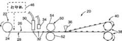
图1是用于制造被光学分度的载有粘合剂段的载体分离带的带卷的制造工艺的示意图。1 is a schematic illustration of a manufacturing process for making a roll of optically indexed adhesive segment loaded carrier release tape.
图2是被分度的载有粘合剂段的载体分离带的一个带段的透视图,该分离带具有可光学检测的分度标志线,所述标志线在分离带上的热塑粘合剂段与一个用于检测该分度标志的光学检测器之间横跨分离带延伸。Figure 2 is a perspective view of a segment of an indexed adhesive segment-laden carrier release tape having optically detectable indexing marking lines on thermoplastic adhesive on the release tape. Extending across the separation zone is a mixture segment and an optical detector for detecting the graduated markings.
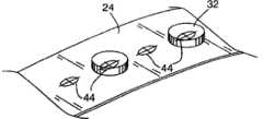
图3是一个与图2相类似的视图,它显示了根据本发明所使用的位于载有粘合剂段的载体分离带上的另一实施例的分度标志。Figure 3 is a view similar to Figure 2 showing another embodiment of index marks on a carrier release tape carrying adhesive segments for use in accordance with the present invention.
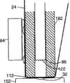
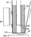
图4是一个方法实施例的详细示意性横断面侧视图,该方法用于在分离带的制造工艺过程中在与热塑粘合剂段相对的载体分离带表面上提供穿孔。Figure 4 is a detailed schematic cross-sectional side view of an embodiment of a method for providing perforations in the surface of the carrier release tape opposite the thermoplastic adhesive segments during the release tape manufacturing process.
图5显示了由图1所示工序制造的被分度的载有粘合剂段的载体分离带带卷的立体图。FIG. 5 shows a perspective view of an indexed roll of adhesive segment-laden carrier release tape produced by the process shown in FIG. 1 .
图6是根据本发明的自动粘合剂段涂敷器设备的一实施例的正视图。Figure 6 is a front view of one embodiment of an automated adhesive segment applicator apparatus in accordance with the present invention.
图7是沿图6中7-7线的自动粘合剂段涂敷器设备的实施例的侧视图。7 is a side view of an embodiment of the automatic adhesive segment applicator apparatus taken along line 7-7 of FIG. 6 .
图8是沿图6中8-8线的根据本发明的粘合剂段涂敷器设备一实施例的带导轨、带夹钳与涂敷器头的更详细的视图。Figure 8 is a more detailed view of the belt rail, belt clamp and applicator head of an embodiment of an adhesive segment applicator apparatus in accordance with the present invention taken along line 8-8 of Figure 6 .
图9是根据本发明的用于一种自动粘合剂段涂敷器设备的一示例性控制系统的示意性方框图。9 is a schematic block diagram of an exemplary control system for an automated adhesive segment applicator apparatus in accordance with the present invention.
图10是显示使用根据本发明的一种粘合剂段分度设备将热塑粘合剂段从载有粘合剂段的载体分离带上涂敷至一工件上的示例性方法的流程图。10 is a flow chart showing an exemplary method of applying thermoplastic adhesive segments from a carrier release tape loaded with adhesive segments to a workpiece using an adhesive segment indexing apparatus in accordance with the present invention .
图11-14示意性地显示了根据本发明的粘合剂段涂敷器设备一实施例的一部分,它们显示了在使用该设备将一个粘合剂段从一个载有粘合剂段的载体分离带上涂敷至一工件期间,上述部分的各个位置。Figures 11-14 schematically show a portion of an embodiment of an adhesive segment applicator device according to the present invention, showing use of the device to transfer an adhesive segment from a carrier carrying an adhesive segment During the application of the separation tape to a workpiece, the various positions of the above-mentioned parts.
具体实施方式Detailed ways
本发明提供了用于以一快速而有效的方式将粘合剂段从一条载有粘合剂段的载体分离带上自动涂敷至一工件或一系列工件上的一种系统与方法。本发明可以使用位于载体分离带上的光学分度标志以确保载体分离带在设备内的精确定位。该系统还使用了一种自动涂敷方法,该方法保证在涂敷工序中完全可靠地将粘合剂段从载体分离带上移至一工件上。根据本发明的示例性的涂敷设备与方法的结构与操作,连同其内所使用的光学分度载体分离带及这种载有粘合剂段的载体分离带的制造都将在下文详细描述。The present invention provides a system and method for automatically applying adhesive segments from an adhesive segment-laden carrier release tape to a workpiece or series of workpieces in a rapid and efficient manner. The present invention may use optical indexing marks on the carrier release tape to ensure precise positioning of the carrier release tape within the device. The system also utilizes an automated application method that ensures a completely reliable transfer of the adhesive segments from the carrier release tape to a workpiece during the application process. The structure and operation of an exemplary coating apparatus and method according to the present invention, together with the optically indexed carrier release tape used therein and the manufacture of such adhesive segment-loaded carrier release tape, will be described in detail below. .
首先结合图1,将对用于根据本发明的自动粘合剂段涂敷方法与设备的载有粘合剂段的载体分离带的示例性制造工序进行描述。一种用于制造根据本发明的载有粘合剂段的载体分离带的系统20设置有一个反张紧卷筒22,该卷筒22固定有一个具有分离差别的载体分离带24的贮料辊,载体分离带24具有一个第一表面26和一个与第一表面相反的第二表面28。该载体分离带24可以由纸制造,并在第一表面26和第二表面28上具有有机硅分离材料。载体分离带24的第一表面26具有比载体分离带24的第二表面28的摩擦系数更大的摩擦系数,于是载体分离带的第一表面26相比载体分离带24的第二表面更不易于分离。First, with reference to FIG. 1 , an exemplary manufacturing process of an adhesive segment-loaded carrier release tape for use in an automated adhesive segment application method and apparatus according to the present invention will be described. A
载体分离带24从张紧卷筒22开始分配,载体分离带24的第一表面26面朝上以在由一个计量泵(未显示)供应热塑粘合剂的一对热塑胶定径喷嘴30(图1中仅可以看见一个)的下面移动,以便当第一表面26移过喷嘴30时将粘合剂段32并排地分配到第一表面26上。空气喷嘴34对准第一表面26,随后冷却粘合剂段32,且该粘合剂段32也随着载体带24的向前移动而被自然对流冷却。The
一个纵切刀36将载体带24分成多个带段,每一带段随后在受控张力下在卷带盘38上卷绕成带卷40。也可以设置绞盘与惰轮,于是卷带盘38上的张力可以被供带盘22所提供的张力单独控制。A
粘合剂段32起初高于载体带24的第一表面26隆起,但是随着其卷绕于卷带盘38上,每个粘合剂段32在载体带24下一连续层的载体带24的第二表面28下被按压,并沉积在载体带24的第一表面26上,从而将粘合剂段压平成为圆盘。可替换地,在卷绕于卷带盘38之前,一个具有非粘表面的冷却滚筒也可用于压平该粘合剂段32。
表面26与28分离特性上的差异,粘合剂段32最初在一热的状态下涂敷至表面26以便产生更好的粘合的事实,以及由于冷却因而使得粘合剂段32在卷绕于卷带盘38之前就“结皮”的事实,所有这些都保证了当带卷40被解绕时,粘合剂段32仍保持粘附于第一表面26。The difference in the separation characteristics of the
应该注意,虽然此处所描述的粘合剂段32基本为圆形,但是本发明也可以使用具有其它二维形状的粘合剂段涂敷于载体分离带上。粘合剂段的形状通常可以由将热塑粘合剂涂敷于载体带24上的热塑胶定径喷嘴30的形状或其它特性确定。It should be noted that although the
根据本发明,载有粘合剂段的载体分离带24具有一系列形成于其上的可光学检测的分度标志。正如下文将会详细描述的那样,这些可光学检测的分度标志被根据本发明的自动粘合剂段涂敷器系统所采用,以便精确地定位被涂敷器所涂敷的粘合剂段。如下所述,例如在图2中,可光学检测的分度标志可以采取线42的形式,所述线42形成于载体分离带24上并在分离带上的粘合剂段32之间横跨分离带24延伸。人们应当理解,在载有粘合剂段的载体分离带上可以使用各种不同的可光学检测的分度标志。例如,如图3所示,可以沿载体带24在规则位置上设置打印记录标志44。According to the present invention, the adhesive segment-laden
无论是采用哪一种分度标志42,44,分度标志42,44可以形成于载体分离带24的一个或者两个表面26,28上。除了形成于载体分离带24的一个或两个表面26,28上之外,分度标志还可以被形成为形成于载体分离带24上的穿孔或者其它切口或孔,这些分度标志可以被一个光学检测器检测到。再如图3所示,所述可光学检测的分度标志44可以被定位在载体分离带24的表面26,28上,不仅是在其上的粘合剂段32之间,而且相对粘合剂段32位于分离带24的表面26,28上的不同位置。例如,载体分离带24上的粘合剂段32可以由一种透明的热塑材料制成,在此情形下,分度标志44可以被部分地或全部地定位于载体分离带24上的粘合剂段32之下,而且仍可被光学检测器检测到。Regardless of which type of index marks 42 , 44 is used, the index marks 42 , 44 may be formed on one or both
最好是,在粘合剂段32沉积在载体分离带24上之前,所述分度标志42,44可以被预印或者被以其它方式形成在载体分离带24之上或之内。可替换地,所述分度标志42,44可以被印刷或者被以其它方式形成在载体分离带24之上或之内,以作为系统20工序的一部分或者由系统20将粘合剂段32沉积在载体带24上的工序的一部分。在此情形下,例如,可以将一台打印机46、诸如一台激光打印机或者类似设备作为系统20的一部分,如图1所示用于制造所述载有粘合剂段的载体分离带。在此情形下,打印机46或者其它设备被用来在将粘合剂段32沉积在载体分离带24上之前在其一个或两个表面上形成分度标志42和44。请注意,假如将要用的分度标志是形成于载体带24之上或之内的物理刻痕、刺孔或穿孔,则可以采用一种不同于打印机46的设备,例如一种其外圆周上设有许多砧模刮刀(die blade)的旋转砧模(rotary die),以便在载体分离带24上形成所述分度标志。总之,不管是由制造者在载体分离带24上印刷或形成,还是在将粘合剂段32涂敷到载体分离带24上的过程中,所述可光学检测的分度标志最好是沿着载体分离带24的长度方向以均匀的间距纵向连续形成于载体分离带24上。Preferably, the index marks 42 , 44 may be pre-printed or otherwise formed on or in the
在将粘合剂段32涂敷到载体分离带24上期间,最重要的是,粘合剂段32是以一致的相对于形成于载体分离带24上的分度标志的位置、沿着载体分离带24的长度方向被沉积在载体分离带24上。为了获得这种将粘合剂段32沉积在载体分离带24上的精确控制,可以如图2所示使用一个光学传感器48或者类似部件来协调分配喷嘴30的操作,以便粘合剂段32能够相对于载体分离带24上的分度标志被正确设置。During the application of the
应当注意到,在一些情形下,沉积在载体分离带24上的粘合剂段32可以被一个光学检测器检测或者做成可检测的,粘合剂段32本身可以被用作分度标志。例如,可以制定用于形成所述粘合剂段32的热塑粘合剂使之具有变化的性能比如粘性等。热塑粘合剂32还可以制定成具有可光学检测性,比如通过将该热塑粘合剂与颜料混合,或者具有其它可光学检测特性。例如,在紫外线辐射下发光是一些热塑粘合剂的固有特性,可以利用这一事实而采用由这种热塑粘合剂所形成的粘合剂段32作为分度标志本身。It should be noted that in some cases the
贯穿本专利申请的其它部分,印刷或者以其它方式形成于载体分离带24之内或之上的分度标志将参考作为如图2所示和所述的示例性线性分度标志42描述。然而,应当知道,在本说明书中以及在权利要求书中所用的术语“分度标志”和“可光学检测的分度”以及任何类似的术语,还涉及到其它类型的分度标志,不管是印刷在载体分离带24之上还是形成在载体分离带24之内,包括沉积在载体分离带24上的可光学检测的粘合剂段32。Throughout the remainder of this patent application, graduation markings printed or otherwise formed in or on
正如在下文中将详细描述的那样,已经发现,为了采用根据本发明的一种自动粘合剂段涂敷器,将粘合剂段32从一个粘合剂段载体分离带24上涂敷到一个工件上,假如使位于该粘合剂段32之下或之后的载体分离带24的一部分被穿孔或者打孔而形成一个或多个穿孔,则可以更好地确保粘合剂段32从该载体分离带24上分离到工件上。正如下文所详细描述地,粘合剂段32背面的载体分离带24上的穿孔根据本发明可以在将粘合剂段32涂敷到一个工件的过程中由一自动粘合剂段涂敷器操作。可替换地,在制造载有粘合剂段的载体分离带的过程中,可以在沉积于载体分离带24上的粘合剂段32背面的载体分离带24上形成一个或多个穿孔。例如,所述粘合剂段32可以被沉积在一条其上已经形成有如此穿孔的载体分离带24上。然而,由于所述粘合剂段32是以液体形式沉积在载体分离带24上的,就有这样的可能,被沉积的液体热塑粘合剂可以渗进载体分离带24上的这些预成形的穿孔,结果导致在载体分离带24的两个相对表面26和28上都有热塑粘合剂。显然,这是不能接受的。As will be described in detail hereinafter, it has been found that in order to employ an automatic adhesive segment applicator according to the present invention, the
作为选择,最好是,假如穿孔要被制成穿透粘合剂段32的背面的载体分离带24,所述粘合剂段32沉积于所述载体分离带24上,那么最好是在所述热塑粘合剂段32已经被沉积于载体分离带上、而且至少是部分地被冷却和被硬化之后,再透过载体分离带24形成这样的穿孔。在图1和图4中,示意性地示出了一种用于在载体分离带24上形成这样穿孔的示例性系统和方法,用标记50表示。在此情形下,一个旋转砧模52以及相应的旋转铁砧54协同动作,以便在沉积于载体分离带24上的每一粘合剂段32的背面的载体分离带24上穿孔。典型地,该旋转砧模52是鼓形的并且在其外圆周上形成有多个刮刀或凸起56。所述旋转铁砧54上形成有相应的凹槽58。载体分离带24在旋转砧模52与旋转铁砧54之间被有效地夹紧。当载体分离带24在旋转砧模52与旋转铁砧54之间通过时,旋转砧模52上的凸起56穿过载体分离带24上的表面28在载体分离带24上冲压出一个或多个孔,所述表面28与粘合剂段32所沉积的表面26相反。形成于旋转砧模52上的所述凸起56最好是足够长以致于穿透载体分离带24而没有全部穿透沉积于其上的粘合剂段32。当分离带24被旋转砧模52穿孔时,带凹槽的旋转铁砧54为载体分离带24提供支承。旋转铁砧54上的凹槽58的大小和形状形成为这样,当载有粘合剂段的载体分离带24通过铁砧54与旋转砧模52之间时,载体分离带24上的粘合剂段32被定位在凹槽58内,从而铁砧54为环绕粘合剂段32的载体分离带24提供支承,而与载体分离带24上的粘合剂段32没有实际上的接触或者挤压。应当知道,尽管这里图示和描述的此实施例示出了给载体分离带24穿孔仅仅是在与其上沉积有粘合剂段32相一致的位置上,但是作为选择,所述穿孔也可以沿着载体分离带24的整个长度形成,只要至少一个这种穿孔是在载体分离带24上在粘合剂段32所沉积的每一个位置上形成即可。Alternatively, preferably, if the perforations are to be made through the
参见图5,示出了已被分度的载有粘合剂段的载体分离带24的一个带卷,其上包含有多个可分配的粘合剂段32。可以看到,该被分度的载有粘合剂段的载体分离带24卷绕在一个中空的圆柱形芯轴62上,该芯轴62例如可以由纸板、塑料或类似材料制成。该芯轴62的内部具有两个被安装或形成于其内的、形状相同的便于定向的片段64和66。所述便于定向的片段64和66将用来使得带卷60以正确的定向容易地安装到一个供给卷轴(下文将详细描述)上。由于芯轴62内部的所述便于定向的片段64和66的存在及其结构,就不可能将带卷60反向放置到供给卷轴上。Referring to Fig. 5, there is shown a roll of adhesive segment loaded
下面将首先结合图6和图7,对根据本发明的一种自动粘合剂段涂敷器装置70进行描述。形成根据本发明的一种自动粘合剂段涂敷器装置70的各种部件被安装在一个可移动的支承结构72上。该可移动的支承结构72可以被制造成比如一个板形结构件,由钢、铝或其它合适的脊状的且坚固的材料制成。该支承结构72被安装成可相对于一个支承结构底座74移动。例如,该支承结构72可以通过一个合适的支座结构76可移动地安装到支承杆轴承78,所述杆轴承78被固定地连接到支承结构底座74上。采用一个支座结构致动设备79,比如一个气动气缸或者类似设备来移动所述支承结构72,在此情形下,使支承结构72在支承杆轴承78上相对于支承结构底座74上下移动。An automatic adhesive segment applicator device 70 according to the present invention will first be described below with reference to FIGS. 6 and 7 . The various components forming an automatic adhesive segment applicator device 70 according to the invention are mounted on a movable support structure 72 . The movable support structure 72 may be manufactured, for example, as a plate-shaped structural member, made of steel, aluminum or other suitable ridged and strong material. The support structure 72 is mounted for movement relative to a support structure base 74 . For example, the support structure 72 may be movably mounted by a suitable standoff structure 76 to a support rod bearing 78 fixedly connected to the support structure base 74 . A support structure actuating device 79, such as a pneumatic cylinder or similar, is used to move said support structure 72, in this case up and down relative to support structure base 74 on support rod bearings 78.
根据本发明的所述自动粘合剂段涂敷器装置70的安装在所述支承结构72上的主要部件包括一个供给卷轴80、一个带导轨82、一个带夹钳84、一个涂敷器头86(设置在带导轨82内,如图8所示)、一个废带收带盘88和一个光学分度标志检测器90。还有连接到支承结构72上的合适的致动器,其包括,比如,一个用于致动带夹钳84的气缸致动器92,一个用于操作涂敷器头86的气缸致动器94,以及一个用于驱动收带盘88的马达96。The main components of the automatic adhesive segment applicator device 70 according to the invention mounted on the support structure 72 include a supply reel 80, a
所述供给卷轴80可以通过一个延伸臂98安装到支承结构72上。该延伸臂98可以以任何常规的和便利的方式被固连到支承结构72上。如上所述,可以用任何传统的方式设置供给卷轴80以支承载有粘合剂段的载体分离带24的一个带卷60。供给卷轴80最好是包括便于定向的片段100和102,它们被这样设计大小、形状和定位,以便与带卷60上的相应的便于定向片段64和66啮合,从而确保带卷60仅在正确的定向上被安装在供给卷轴80上,即这样的定向,其上具有粘合剂段32的载体分离带24的表面26被指引通过所述粘合剂段分度涂敷器装置70,该装置用于给工件涂敷粘合剂段。供给卷轴80最好是设置成可以允许卷轴80旋转,从而,在所述粘合剂段涂敷器装置70的正常运转期间,当带被从带卷60上拉出时,载有粘合剂段的载体分离带24可以被从带卷60上解绕。然而,最好是以任何传统方式提供足够的抗旋转阻力,以防止供给卷轴80在其它状态下自由旋转,从而防止安装在供给卷轴80上的带卷60发生非故意的解绕。The supply spool 80 may be mounted to the support structure 72 by an extension arm 98 . The extension arm 98 may be secured to the support structure 72 in any conventional and convenient manner. As noted above, the supply spool 80 may be arranged in any conventional manner to support a
所述带导轨82是细长的,具有两个相对的细长侧面104和106,在粘合剂段涂敷器70运行期间,所述载有粘合剂段的载体分离带24就沿着这两个侧面伸直。带导轨82的侧面104和106最好是被设计成,有利于对载体分离带24绕着带导轨82通过涂敷器头86进行导向,其中涂敷器头86设置在带导轨82内部,并且在操作期间从带导轨82的一端108延伸。为了实现载体分离带24绕带导轨82的导向,带导轨82的侧面104和106可以设置轨道110或者其它类似结构,它们以稍微大于所述载有粘合剂段的载体分离带24的宽度的距离沿着带导轨82的侧面104和106相间隔。在运行期间,当载有粘合剂段的载体分离带24移动通过粘合剂段涂敷器70时,所述轨道110或其它结构有助于防止载有粘合剂段的载体分离带24滑出载体导轨82。在带导轨82的侧面104和106与端面108之间的过渡段112最好是圆形的且平滑的,以利于载有粘合剂段的载体分离带24绕带导轨82的运动而不会导致损坏带24或者导致粘合剂段32从其上非故意的脱落。The
所述带夹钳84被设计成,在一个粘合剂段32从载体分离带24上涂敷到一个工件上的期间,使得载有粘合剂段的载体分离带24牢牢地定位抵靠在带导轨82上。如图8所示,带夹钳84最好是包括有从其上沿带导轨82的一个侧面104的方向上延伸的突出部114。当通过操作带夹钳致动器92,使带夹钳84在带导轨82的方向上移动时,带夹钳突出部114将载有粘合剂段的载体分离带24夹紧在突出部114与带导轨82的侧面104之间,从而防止载有粘合剂段的载体分离带24移动。突出部114彼此间隔一定距离,以致在两者之间形成一个缺口116,从而当带夹钳84闭合抵靠在带导轨82上时,除了突出部114外带夹钳84的本体保持与带导轨82相互远离,因而防止带夹钳84与沉积在载有粘合剂段的载体分离带24上的粘合剂段32发生接触,此时载体分离带24在带夹钳84与带导轨82之间通过。请注意,带夹钳致动器92可以以任何传统的方式实现,比如,采用一个利用气压和/或弹簧回复的气动气缸。The
请注意,在粘合剂段涂敷器70运行期间,重要的是,在涂敷器头86动作以将一个粘合剂段32涂敷到一个工件上期间,载有粘合剂段的载体分离带24被牢固地保持在相对于涂敷器头86的位置。这比如通过在带导轨82的两个侧面104和106上设置一个带夹钳84而可以实现。作为选择,可以采用单个带夹钳84,如图6所示,其中,在带导轨82的远离带夹钳84的相对侧面上设置一个夹送滚轮装置118。可以采用一种传统的夹送滚轮装置118,粘合剂段32已经从其上移除的用过的载体分离带24通过该夹送滚轮装置118而被伸展,而且该夹送滚轮装置118仅允许载体分离带24在一个经过该控制器装置118直至收带盘88的方向上运动。Please note that during the operation of the adhesive segment applicator 70, it is important that the carrier carrying the adhesive segment be The
所述涂敷器头86最好是被安装成在一个形成于并贯通带导轨82的内孔120中进行轴向运动,从而该涂敷器头86可以移进或移出带导轨82以便从带导轨82的端面108处的内孔120延伸。涂敷器头86的大小和形状最好是大体上与粘合剂段32的大小相一致,粘合剂段32将被涂敷器头86涂敷到工件上。涂敷器头86最好是包括至少一个、最好是多个从其上延伸的尖锐凸起122。正如下文将详细描述的那样,在粘合剂段涂敷器70运行期间,涂敷器头致动器94被操作而将涂敷器头86从带导轨82的端面108向外移动,以便与在一个粘合剂段32对面的载体分离带24的表面28接触,从而将该粘合剂段32压靠在一个工件上以将该粘合剂段32涂敷到该工件上。设计凸起122的大小,并协调涂敷器头82的运动,以便在粘合剂段32的背面刺穿载体分离带24,最好是没有完全刺透粘合剂段32而至工件,其中该粘合剂段32被沉积在该工件上。在涂敷过程中,以此方式形成刺穿分离带24的孔,这有利于粘合剂段32从载体分离带24上释放到工件上,以便在利用本发明的粘合剂段涂敷器70将粘合剂段32快速自动地涂敷到一个工件上期间,确保粘合剂段32可靠地涂敷到该工件上。The
所述收带盘88可以被设计成一种传统的旋转卷轴,当粘合剂段32已经被从载体分离带24上移除之后,载体分离带24就卷绕在卷轴上。收带盘88最好是可以被一台马达96驱动,比如一台步进或伺服马达。如图所示,收带盘马达96可以被安装在位于支承结构板72的与收带盘88相对的侧面上。一根驱动轴可以从马达96延伸穿过支承结构72而直接啮合并驱动所述夹送滚轮装置118。一条连接在夹送滚轮装置118与收带盘88之间的传动带126将收带盘88连接到马达96上。在运行时,操作马达96以使夹送滚轮装置118和收带盘88旋转,以便将载体分离带24从安装在供给卷轴80上的带卷60上拉出,载体分离带24环绕带导轨82被伸展。The take-up reel 88 may be designed as a conventional rotating reel on which the
根据本发明,采用一种光学分度标志检测器90来检测形成于所述载有粘合剂段的载体分离带24上的分度标志42。该光学检测器90可以以任何传统方式实现,并且具体选择和实施以检测形成于载体分离带24上或内的特定类型的分度标志。该光学分度标志检测器90可以被安装在支承结构72上的任何合适和便利的位置以检测所述分度标志42。According to the present invention, an optical index mark detector 90 is used to detect index marks 42 formed on the adhesive segment-laden
下面将结合图9,对根据本发明的一种用于粘合剂段涂敷器的示例性控制系统130进行详细的描述。该系统控制器132可以以一种传统方式实施以实现这里描述的功能。比如,可以通过整体地或部分地采用一个微处理器或者其它可编程设备和/或采用考虑周到的数字和/或模拟电路相结合,来实施该控制器132。该控制器132可以但不是必须被安装到粘合剂段涂敷器的支承结构72上。An exemplary control system 130 for an adhesive segment applicator according to the present invention will be described in detail below with reference to FIG. 9 . The system controller 132 may be implemented in a conventional manner to carry out the functions described herein. For example, the controller 132 may be implemented in whole or in part by a microprocessor or other programmable device and/or by a combination of thoughtful digital and/or analog circuits. The controller 132 may, but need not, be mounted to the support structure 72 of the adhesive segment applicator.
所述光学分度标志检测器90作为一个带位置传感器来操作,其给所述系统控制器132提供一种关于分度标志42在载体分离带24上的检测位置的输入信息。该控制器132对从所述带位置传感器90接收到的信号进行处理,以便用一种传统方式来确定载有粘合剂段的载体分离带24的位置。在控制涂敷器70以从载体分离带24上将一个粘合剂段32涂敷到一个工件上之前,该控制器132基于从所述带位置传感器90接收到的信号来确定载有粘合剂段的载体分离带24是否正确就位,从而一个粘合剂段32被定位在带导轨82的端面108上以便被涂敷器头86涂敷到一个工件上。假如一个粘合剂段32不在所希望的位置上,则控制器132就通过一个合适的传统马达控制器134给带推进马达96发送一个控制信号,以使夹送滚轮装置118和收带盘88旋转,将载有粘合剂段的载体分离带24从供给带卷60上向前推进,直至来自带位置传感器90的信号显示出一个粘合剂段32正处于所希望的位置上。(最好是提供一个手动的刻度输入136,假如通过观察确定了控制器132不是将粘合剂段正确定位在所希望的位置上以便于涂敷到一个工件上,则向控制器132提供一个输入)。The optical index mark detector 90 operates as a belt position sensor which provides an input to the system controller 132 regarding the detected position of the
一旦所述载有粘合剂段的载体分离带24被如此定位,使得粘合剂段32被定位在带导轨82的端面108处的适合位置上,控制器就向支承结构致动器79、带夹钳致动器92以及涂敷器头致动器94发送合适的控制信号,以便自动地顺序地控制它们的运行,而采用一种下文将详细描述的方式自动地将该粘合剂段涂敷到一个工件上。此涂敷工序可以从手动操作开始,比如通过一个人工触发器138,该触发器138向控制器132提供一个触发信号。该人工触发器138可以比如作为一个手或脚操作的开关来实施,当操作者将一个工件定位在所需位置上或者注意到一个工件正处于所需位置上以等待一个粘合剂段32涂敷于其上时,该开关给控制器提供一个触发信号以开始粘合剂段涂敷程序。作为选择,可以由一输送机或者其它与工件相关的触发器140来自动地开始所述粘合剂段涂敷工序。比如,这样一种工件触发器140可以提供一个触发信号以开始将粘合剂段32涂敷到一个工件上,采用一个传统系统来检测一个工件相对于粘合剂段涂敷器70存在于正确位置上。这样一种自动工件触发器140可以、特别是应用于装配线类型的装置上。Once the adhesive segment-laden
如前所述,支承结构致动器79、带夹钳致动器92以及涂敷器头致动器94可以采用气动气缸类型的致动器。在此情形下,提供用来操作如此致动器的控制信号是由控制器132提供给合适的相应开关设备142,144和146以将压缩空气从一个压缩空气源148导引到合适的气缸致动器79,92和94,以便在需要的时候且以需要的方式操作致动器。请注意,最好仅使用一个单一压缩空气源148给涂敷器装置70中所用的所有气缸致动器79,92和94提供动力源。As previously mentioned, the support structure actuator 79, the band clamp actuator 92, and the applicator head actuator 94 may be pneumatic cylinder type actuators. In this case, the control signals provided to operate such actuators are provided by the controller 132 to the appropriate corresponding switchgear 142, 144 and 146 to direct compressed air from a compressed air source 148 to the appropriate cylinder. Actuators 79, 92 and 94 are used to operate the actuators when and in the desired manner. Note that only a single compressed air source 148 is preferably used to power all of the air cylinder actuators 79, 92 and 94 used in the applicator assembly 70.
下面将结合图10的示例性流程图表以及图11-14,对一种用于操作根据本发明的一种粘合剂段涂敷器装置的示例性方法进行描述,该方法用以将一个粘合剂段32从载有粘合剂段的载体分离带24涂敷到一个工件152上。图11-14示意性地示出,在粘合剂段涂敷器运行期间,在不同点上,载有粘合剂段的载体分离带24、带导轨82、带夹钳84、涂敷器头86以及工件152的相对位置。An exemplary method for operating an adhesive segment applicator device according to the present invention for applying an adhesive segment will now be described with reference to the exemplary flow diagram of FIG. The
所述系统控制器132首先利用从带位置传感器90提供的信号来确定粘合剂段涂敷器装置70中带24的位置154。具体是,控制器利用带位置传感器90来确定带是否正确就位156,以致一个粘合剂段32被定位在带导轨82的端面108上并且在内孔120的开口前方,其中涂敷器头86被定位于此孔中。假如载有粘合剂段的载体分离带24未处于所希望的位置,则控制器给带推进马达96发送合适的信号以使带前进158,直至来自于带位置传感器90的信号显示出带处于所需位置上。The system controller 132 first uses the signal provided from the belt position sensor 90 to determine the
然后控制器132等待一个触发信号160。如上所述,当工件152处于所需位置上以便粘合剂段涂敷于其上时,可以通过操作者手动或者自动地由一个工件定位或检测系统来提供所述触发信号。当控制器等待该触发信号时,载有粘合剂段的载体分离带24配置有一个准备涂敷到工件152上的粘合剂段32上,装置部件正处于图11所示的位置。The controller 132 then waits for a
当接收到一个触发信号,显示出一个工件正位于一个粘合剂段要被涂敷至其上的位置后,控制器132向带夹钳致动器92发送一个信号以致动带夹钳84并因而夹紧162带,载有粘合剂段的载体分离带24这样就位,以致于在将被涂敷到工件上的粘合剂段32的区域内,带24不会移动。When a trigger signal is received indicating that a workpiece is positioned where an adhesive segment is to be applied, the controller 132 sends a signal to the band clamp actuator 92 to actuate the
随着带被夹紧,控制器132向支承结构致动器79发送一个信号,以降低支承结构72,并使得将要被涂敷到工件152上的粘合剂段32开始与工件152接触。在夹紧162带和降低164支承结构72之后,所述装置处于如图12所示的位置。With the tape clamped, the controller 132 sends a signal to the support structure actuator 79 to lower the support structure 72 and bring the
然后,控制器132给涂敷器头致动器94提供一个信号以快速降低166致动器头86而抵靠在载体分离带24的与粘合剂段32相对的侧面上。如图13所示,此操作将粘合剂段32压靠在工件152上,从而将粘合剂段32涂敷到工件152上。同时,所述尖锐凸起122在分离带24上形成一个或多个穿孔,但最好是没有穿透粘合剂段32而至工件152。之后,控制器132可以将合适的信号发送给涂敷器头致动器94以使涂敷器头回缩168到带导轨82内。应当相信,当涂敷器头86从欲将已被涂敷到工件152上的粘合剂段32从该工件152上往回拉而回缩时,因在粘合剂段32后面的分离带24上刺有孔或小孔,可防止在粘合剂段32之后形成空气压力。因而,在粘合剂段32后面的分离带24上形成一个或多个穿孔可以确保粘合剂段32从分离带24上分离并完成向工件152的涂敷。Controller 132 then provides a signal to applicator head actuator 94 to quickly lower 166
最好是,对于每一个将被涂敷到一个工件上的粘合剂段32而言,使涂敷器头86伸出166和回缩168的步骤可以快速重复170至少一次。这进一步确保粘合剂段32从载体分离带24上释放并涂敷到工件152上。Preferably, the step of extending 166 and retracting 168 the
当涂敷器头86已经运行而将粘合剂段32涂敷到工件152上之后,控制器132可以发送一个控制信号给支承结构致动器79以将支承结构72升高而回到它的起始位置,并可以发送一个信号给带夹钳致动器92以释放174带夹钳92而允许所述载有粘合剂段的载体分离带24移动。当已经将一个粘合剂段32涂敷到工件152上之后,控制器132然后可以发送一个控制信号给带推进马达96以将载有粘合剂段的载体分离带24向前推进,以便将下一个粘合剂段定位在载体分离带上的正确位置以用于涂敷到一个工件上,如图14所示。如上所述,比如,可以利用所述光学带位置传感器90来检测载体分离带24上的分度标志42,以确保载体分离带24上的该下一个粘合剂段32处于正确的位置上。After the
应当知道,本发明并不局限于这里所描述和图示的具体示例性应用和实施例。特别是,尽管这里图示和描述的示例性粘合剂段涂敷器装置70通常是相对于在涂敷器70下方的工件152位置沿垂直方向上上下移动,但是,根据本发明的一种粘合剂段涂敷器装置可以相对于一个工件被定位在任何方向上并且相对于它被定向和操作,以将一个粘合剂段从一条粘合剂段载体分离带上涂敷到该工件上。It should be understood that the present invention is not limited to the specific exemplary applications and embodiments described and illustrated herein. In particular, although the exemplary adhesive segment applicator assembly 70 shown and described herein generally moves up and down in a vertical direction relative to the position of the
Claims (10)
Applications Claiming Priority (2)
| Application Number | Priority Date | Filing Date | Title |
|---|---|---|---|
| US10/920,151 | 2004-08-17 | ||
| US10/920,151US7837815B2 (en) | 1997-02-06 | 2004-08-17 | Adhesive segment indexing method and apparatus and roll of adhesive segments for use therewith |
Related Child Applications (1)
| Application Number | Title | Priority Date | Filing Date |
|---|---|---|---|
| CN2012100253595ADivisionCN102602734A (en) | 2004-08-17 | 2005-08-16 | Adhesive segment distribution tape |
Publications (2)
| Publication Number | Publication Date |
|---|---|
| CN1760299A CN1760299A (en) | 2006-04-19 |
| CN1760299Btrue CN1760299B (en) | 2012-04-04 |
Family
ID=35115706
Family Applications (2)
| Application Number | Title | Priority Date | Filing Date |
|---|---|---|---|
| CN2012100253595APendingCN102602734A (en) | 2004-08-17 | 2005-08-16 | Adhesive segment distribution tape |
| CN2005101067495AExpired - Fee RelatedCN1760299B (en) | 2004-08-17 | 2005-08-16 | Adhesive segment indexing method and apparatus and roll of adhesive segments for use therewith |
Family Applications Before (1)
| Application Number | Title | Priority Date | Filing Date |
|---|---|---|---|
| CN2012100253595APendingCN102602734A (en) | 2004-08-17 | 2005-08-16 | Adhesive segment distribution tape |
Country Status (7)
| Country | Link |
|---|---|
| US (2) | US7837815B2 (en) |
| EP (1) | EP1627837B1 (en) |
| CN (2) | CN102602734A (en) |
| AT (1) | ATE427906T1 (en) |
| DE (1) | DE602005013727D1 (en) |
| ES (1) | ES2323473T3 (en) |
| PL (1) | PL1627837T3 (en) |
Cited By (1)
| Publication number | Priority date | Publication date | Assignee | Title |
|---|---|---|---|---|
| WO2024132760A1 (en)* | 2022-12-22 | 2024-06-27 | Tesa Se | Application system having a transfer belt |
Families Citing this family (16)
| Publication number | Priority date | Publication date | Assignee | Title |
|---|---|---|---|---|
| US20080099132A1 (en)* | 2006-10-27 | 2008-05-01 | Glue Dots International, Llc | Product driven in-line glue dot applicator and method for using same |
| US20080099510A1 (en) | 2006-10-27 | 2008-05-01 | Glue Dots International, Llc | Product Driven In-Line Glue Dot Applicator And Method For Using Same |
| NL1033386C1 (en)* | 2007-02-13 | 2008-08-14 | Gerard Dietz | Device for removing adhesive units from a carrier tape, called a dispenser. |
| DE102007056778B4 (en) | 2007-11-23 | 2021-05-27 | Lohmann Gmbh & Co. Kg | Method of making a combination adhesive device |
| WO2010021025A1 (en)* | 2008-08-19 | 2010-02-25 | 日東電工株式会社 | Method for cutting optical film and device employing the method |
| CN101885951B (en)* | 2009-05-15 | 2013-10-02 | 友达光电(厦门)有限公司 | Aeolotropic conductive tape and attaching device and attaching method thereof |
| KR101148536B1 (en)* | 2010-07-26 | 2012-05-21 | 이도희 | Method of manufacturing a promotion tab end for a can |
| CH703698A1 (en)* | 2010-09-03 | 2012-03-15 | Roland F Gratzer | An apparatus for position-accurate applying of elements on a surface of an object. |
| WO2012116806A1 (en)* | 2011-02-28 | 2012-09-07 | Gratzer! Technologies Gmbh & Co. Kg | Apparatus for fixing rigid decorative bodies from a transfer strip onto a substrate |
| US20140150959A1 (en)* | 2011-07-19 | 2014-06-05 | Gratzer! Technologies Gmbh & Co. Kg | Method and apparatus for fixing rigid decorative elements on a substrate, and carrier strip with decorative elements |
| ITVR20110205A1 (en)* | 2011-11-17 | 2013-05-18 | G S M S R L | PROCEDURE FOR APPLICATION OF DECORATIVE ELEMENTS |
| USD708666S1 (en) | 2011-11-18 | 2014-07-08 | Glue Dots International, Llc | Dispenser |
| US20130193249A1 (en)* | 2012-01-31 | 2013-08-01 | Georgia-Pacific Consumer Products Lp | Product, Dispenser and Method of Dispensing Product |
| US20180112108A1 (en)* | 2016-10-20 | 2018-04-26 | The Boeing Company | Segmented film adhesive, method of making the adhesive and method of applying the adhesive to a non-planar surface |
| CN108172705A (en)* | 2017-11-13 | 2018-06-15 | 东莞市德尔能新能源股份有限公司 | A kind of mobile phone internal battery pastes protection foam device and method automatically |
| US12252293B2 (en)* | 2021-03-22 | 2025-03-18 | Zebra Technologies Corporation | Adhesive label application system for a robotic device |
Citations (2)
| Publication number | Priority date | Publication date | Assignee | Title |
|---|---|---|---|---|
| US6319442B1 (en)* | 1997-02-06 | 2001-11-20 | Glue Dots International, Llc | Process of making a thermoplastic adhesive dispensing tape |
| US6596105B2 (en)* | 2001-05-03 | 2003-07-22 | Rock-Tenn Company | High-speed label applicator |
Family Cites Families (124)
| Publication number | Priority date | Publication date | Assignee | Title |
|---|---|---|---|---|
| FR2730698B1 (en)* | 1995-02-22 | 1997-05-09 | Euro Label 06 | AUTOMATIC PRODUCT LABELING SYSTEM |
| US2276297A (en)* | 1938-12-31 | 1942-03-17 | Dennison Mfg Co | Label dispenser |
| US2373092A (en)* | 1940-08-02 | 1945-04-10 | Avery Ray Stanton | Label and tape dispensing machine |
| US2278297A (en) | 1941-10-16 | 1942-03-31 | Socony Vacuum Oil Co Inc | Handling thermophore mixtures |
| GB681096A (en) | 1948-07-13 | 1952-10-15 | Clarence Wedekind Vogt | Improvements in or relating to bag arrangements |
| US2647843A (en)* | 1950-03-29 | 1953-08-04 | Permacel Tape Corp | Adhesive tape |
| US2754994A (en)* | 1951-02-21 | 1956-07-17 | Kleen Stik Products Inc | Label dispenser |
| GB780291A (en) | 1954-10-15 | 1957-07-31 | Dominic Anthony Sanni | Improvements in shaker dispenser packets and manufacture thereof |
| US2838171A (en)* | 1956-03-15 | 1958-06-10 | Paramount Paper Products Compa | Price tag dispenser |
| US2847843A (en) | 1956-09-06 | 1958-08-19 | Royal Sales Company | Cigarette lighter |
| NL123671C (en)* | 1956-10-16 | 1900-01-01 | ||
| US2912140A (en)* | 1957-03-07 | 1959-11-10 | Kleen Stik Products Inc | Label dispenser |
| US3161554A (en) | 1958-11-05 | 1964-12-15 | Johnson & Johnson | Adhesive tape |
| US3068881A (en) | 1959-02-06 | 1962-12-18 | Gen Motors Corp | Make-up valve for air system |
| US3066881A (en)* | 1959-09-25 | 1962-12-04 | Minnesota Mining & Mfg | Label dispenser |
| US3085572A (en) | 1961-10-06 | 1963-04-16 | Johnson & Johnson | Tape |
| US3225916A (en)* | 1963-01-09 | 1965-12-28 | Dayton Abrasive Products Inc | Assemblage of abrasive elements |
| US3267623A (en)* | 1963-02-08 | 1966-08-23 | Merit Products Inc | Abrasive article |
| US3308002A (en)* | 1963-11-27 | 1967-03-07 | Dymo Industries Inc | Method and apparatus for application of pressure sensitive adhesive material |
| US3308802A (en)* | 1964-04-20 | 1967-03-14 | Applegate Earl | Power driven baseball pitching machine with batter signalling means |
| US3239403A (en)* | 1965-01-06 | 1966-03-08 | Lord Corp | Method of joining two members by means of an adhesive coated carbon cloth resistance member |
| US3464883A (en)* | 1965-12-20 | 1969-09-02 | Avery Products Corp | Self-contained,solvent-retaining,pressure-sensitive adhesive product |
| US3445263A (en)* | 1966-05-24 | 1969-05-20 | Hercules Inc | Pressure sensitive adhesive tape |
| US3457919A (en)* | 1966-06-22 | 1969-07-29 | Smith & Nephew | Adhesive surgical and other tapes,plasters,bandages,dressings,and the like |
| NL6617858A (en) | 1966-12-20 | 1968-06-21 | ||
| US3567148A (en)* | 1968-06-13 | 1971-03-02 | Allamatic Corp | Constant tension paper supply mechanism |
| US3736281A (en)* | 1968-06-25 | 1973-05-29 | Flintkote Co | Method of making pressure-sensitive hot-melt adhesives |
| US3582438A (en)* | 1968-11-04 | 1971-06-01 | Marion E Harbour | Tape handling tool |
| US3587148A (en) | 1968-12-27 | 1971-06-28 | Rca Corp | Method of assembly of electron tubes |
| US3877959A (en)* | 1969-06-13 | 1975-04-15 | Sigmond Weiss | Method of fabricating seaming tape |
| US3619324A (en)* | 1969-06-26 | 1971-11-09 | Sato Kiko Kk | Miniature labeling apparatus |
| US3501365A (en)* | 1969-07-11 | 1970-03-17 | Litton Business Systems Inc | Pressure sensitive label strip construction |
| BE756865A (en)* | 1970-01-05 | 1971-03-01 | Acumeter Lab | FLUID APPLICATOR |
| US3741486A (en)* | 1970-06-18 | 1973-06-26 | I Kawamata | Ice shaving device for home use |
| US3741786A (en) | 1971-05-28 | 1973-06-26 | Avery Products Corp | Transfer tape having non-contiguous pressure sensitive adhesive patterns |
| US3932328A (en)* | 1971-11-02 | 1976-01-13 | Johnson & Johnson | Hot melt adhesive composition and tape |
| DE2237923A1 (en)* | 1972-08-02 | 1974-02-21 | Guetermann & Co | DEVICES FOR JOINING TEXTILE FABRICS IN PARTICULAR WITH WELDING OR HEAT SEALABLE POLYMERS |
| CA1035092A (en) | 1973-02-20 | 1978-07-18 | E.I. Du Pont De Nemours And Company | Soft thermoplastic segmented copolyesters as pressure sensitive adhesives |
| US3932326A (en)* | 1973-02-20 | 1976-01-13 | E. I. Du Pont De Nemours And Company | Soft thermoplastic segmented copolyesters as pressure sensitive adhesives |
| US3957724A (en) | 1973-12-11 | 1976-05-18 | Minnesota Mining And Manufacturing Company | Stratum having release properties and method of making |
| US4100852A (en)* | 1974-03-07 | 1978-07-18 | Monarch Marking Systems, Inc. | Label printing apparatus |
| US3969181A (en)* | 1974-06-03 | 1976-07-13 | Minnesota Mining And Manufacturing Company | Transfer adhesive dispensing device |
| US3956223A (en)* | 1974-07-01 | 1976-05-11 | Borden, Inc. | Hot-melt pressure-sensitive adhesive |
| US4002794A (en)* | 1975-07-18 | 1977-01-11 | Nashua Corporation | Adhesive material and articles incorporating same |
| US4454180A (en)* | 1975-10-01 | 1984-06-12 | Mers Herbert | Labelling system |
| US4116746A (en)* | 1977-03-07 | 1978-09-26 | Monarch Marking Systems, Inc. | Hand-held labeler |
| US4211805A (en)* | 1977-05-27 | 1980-07-08 | Cel-U-Dex, Inc. | Self-adhesive labeling article |
| US4719261A (en)* | 1978-09-22 | 1988-01-12 | H. B. Fuller Company | Hot melt adhesive for elastic banding and method for utlizing the same |
| US4543099A (en)* | 1978-12-06 | 1985-09-24 | H. B. Fuller Company | Method for imparting elastic properties to a flexible substrate |
| US4272311A (en)* | 1979-05-17 | 1981-06-09 | Angelo Joseph J D | Method and apparatus for automatically labelling containers |
| US4287255A (en)* | 1979-09-06 | 1981-09-01 | Avery International Corporation | Reinforced adhesive tapes |
| US4294357A (en)* | 1980-01-10 | 1981-10-13 | Kennecott Corporation | Pop up abrasive disc dispenser |
| DE3024869C2 (en)* | 1980-07-01 | 1982-06-09 | Th. Goldschmidt Ag, 4300 Essen | Use of a mixture of an acrylate-based copolymer and an isocyanate as a curable adhesive |
| US4387831A (en)* | 1980-12-17 | 1983-06-14 | Claire O. McNally | Container for dispensing articles carried on a web |
| US4440830A (en)* | 1981-04-16 | 1984-04-03 | Wempe Lawrence K | Substrates coated with release composition based on polyvinyl alcohol and composites with pressure sensitive adhesives |
| GB2109773B (en)* | 1981-07-29 | 1985-08-21 | Bin Chang Sang | Dispensing label strip |
| DE83081T1 (en) | 1981-12-28 | 1984-01-05 | Kabushiki Kaisha Sato, Tokyo | LABEL REMOVER. |
| US4402794A (en)* | 1982-05-24 | 1983-09-06 | Atlantic Richfield Company | Purification of butylene oxides by extractive distillation with selected extractive distillation solvents |
| US4552608A (en)* | 1983-09-16 | 1985-11-12 | B & H Manufacturing Company | System for computer controlled labeling machine |
| US4961804A (en)* | 1983-08-03 | 1990-10-09 | Investment Holding Corporation | Carrier film with conductive adhesive for dicing of semiconductor wafers and dicing method employing same |
| US4508588A (en)* | 1983-08-15 | 1985-04-02 | Parrish John T | Scraper for removing labels or the like |
| US4470864A (en)* | 1983-09-01 | 1984-09-11 | Tennessee Imports | Pneumatic labelling apparatus |
| US4562102A (en) | 1984-03-01 | 1985-12-31 | Minnesota Mining And Manufacturing Company | Roll of predetermined length strips of pressure-sensitive tape |
| US5158818A (en)* | 1984-01-30 | 1992-10-27 | National Starch And Chemical Investment Holding Corporation | Conductive die attach tape |
| US4731066A (en)* | 1984-03-30 | 1988-03-15 | Personal Products Company | Elastic disposable diaper |
| US4959008A (en)* | 1984-04-30 | 1990-09-25 | National Starch And Chemical Investment Holding Corporation | Pre-patterned circuit board device-attach adhesive transfer system |
| US5049434A (en)* | 1984-04-30 | 1991-09-17 | National Starch And Chemical Investment Holding Corporation | Pre-patterned device substrate device-attach adhesive transfer system |
| JPH018499Y2 (en)* | 1985-01-30 | 1989-03-07 | ||
| US4851278A (en)* | 1986-08-11 | 1989-07-25 | Minnesota Mining And Manufacturing Company | Acrylate hot melt adhesive containing zinc carboxylate |
| US4718971A (en)* | 1986-10-09 | 1988-01-12 | Moore Push-Pin Company | Dispenser for a transfer adhesive |
| FR2606784B1 (en)* | 1986-11-14 | 1989-03-03 | Rhone Poulenc Multi Tech | ELECTRICALLY CONDUCTIVE POTENTIALLY ADHESIVE COMPOSITION |
| US4851074A (en)* | 1987-05-27 | 1989-07-25 | Uchida Hiromichi | Automatic transferring device for double-coated adhesive tape |
| GB8719483D0 (en) | 1987-08-18 | 1987-09-23 | Colorwave Peel A Print Ltd | Print mounting systems |
| US4804437A (en)* | 1987-09-10 | 1989-02-14 | Santono Tirtoprodjo | Tape dispenser |
| US4822687A (en)* | 1988-01-22 | 1989-04-18 | Minnesota Mining And Manufacturing Company | Silicone release compositions |
| US4985499A (en)* | 1988-02-22 | 1991-01-15 | Kuraray Company Ltd. | Pressure sensitive adhesive composition |
| US4965113A (en)* | 1988-02-29 | 1990-10-23 | The Excello Specialty Company | Transfer adhesive sandwich and method of applying adhesive to substrates |
| CA1328642C (en)* | 1988-03-31 | 1994-04-19 | Philip Anthony Ratermann | Merchandising label printer/applier |
| US4846924A (en)* | 1988-06-16 | 1989-07-11 | Monarch Marking Systems, Inc. | Method and apparatus for converting hand-held thermal labeler to a table top printer |
| GB8817239D0 (en) | 1988-07-20 | 1988-08-24 | Adhesive Materials Ltd | Adhesive labels & methods for their manufacture |
| DE3843068A1 (en)* | 1988-12-21 | 1990-06-28 | Esselte Meto Int Gmbh | DEVICE FOR FEEDING A LABEL TAPE |
| US5202169A (en)* | 1991-01-23 | 1993-04-13 | Spendlove Max J | Releasable fastener, method of releasably fastening, and releasable fastener dispenser |
| US5316613A (en)* | 1991-09-06 | 1994-05-31 | Minnesota Mining And Manufacturing Company | Definite length transfer adhesive dispenser |
| CA2115673C (en)* | 1991-09-12 | 2003-04-08 | Clyde D. Calhoun | Patterned pressure sensitive adhesive transfer tape |
| US5254206A (en)* | 1992-01-31 | 1993-10-19 | Wing Donald B | Hand-held labeling device |
| US5431763A (en)* | 1992-11-19 | 1995-07-11 | Boss Systems, L.L.C. | Linerless labeling system |
| US5486254A (en)* | 1993-01-21 | 1996-01-23 | Total Register, Inc. | Dual drive registration system |
| US5499877A (en) | 1993-04-06 | 1996-03-19 | Fujicopian Co., Ltd. | Transfer ribbon cassette, a case for enclosing the cassette, and a paint film transfer device having the same |
| DE4319023C1 (en) | 1993-06-01 | 1994-09-29 | Neschen Hans Gmbh & Co Kg | Pressure-sensitive, unsupported, double-sided adhesive tape, and use of a polyacrylic ester contact adhesive for its preparation |
| US5456792A (en)* | 1993-11-15 | 1995-10-10 | Sandar Industries, Inc. | Adhesive dispenser |
| US5486259A (en)* | 1994-01-05 | 1996-01-23 | Monarch Marking Systems, Inc. | Labeler with adjustable roll mounting means |
| US5685944A (en)* | 1994-04-28 | 1997-11-11 | Fujicopian Co., Ltd. | Film transfer apparatus and a film transfer roller used therein |
| CH689975A5 (en)* | 1994-05-24 | 2000-02-29 | Bobst Sa | Safety device in a platen press for processing plate elements. |
| US5489453A (en)* | 1994-06-13 | 1996-02-06 | Friesch; Andrew J. | Adhesive storage and shipment container |
| US5575097A (en)* | 1995-03-16 | 1996-11-19 | Jeffrey P. Chou | Page turning device |
| US5725719A (en)* | 1995-06-26 | 1998-03-10 | Wallace Computer Services, Inc. | Linerless label product, method of making, apparatus and method for dispensing the product |
| US5779852A (en)* | 1996-06-11 | 1998-07-14 | Sensormatic Electronics Corporation | Handheld applicator |
| US5875715A (en)* | 1996-06-19 | 1999-03-02 | Monarch Marking Systems, Inc. | Hand-held labeler |
| US5910227A (en)* | 1996-08-22 | 1999-06-08 | Monarch Marking Systems, Inc. | Hand-held labeler |
| US5988249A (en)* | 1996-08-22 | 1999-11-23 | Monarch Marking Systems, Inc. | Hand-held labeler |
| US20030118771A1 (en)* | 1997-02-06 | 2003-06-26 | Downs John P. | Roll of adhesive segments for use in an adhesive segment applicator apparatus and method of making the same |
| US7195049B2 (en) | 1997-02-06 | 2007-03-27 | Glue Dots International, Llc | Handheld mechanical adhesive segment applicator apparatus and method |
| US20030164220A1 (en) | 1997-02-06 | 2003-09-04 | Downs John P. | Stand and pneumatic actuator for adhesive segment applicator apparatus |
| US6143105A (en)* | 1998-04-27 | 2000-11-07 | Moore U.S.A., Inc. | Semi-automatic mailpiece printer/label applicator |
| US6230780B1 (en)* | 1998-04-30 | 2001-05-15 | Automated Systems Technology, L.L.C. | Label applicator mechanism and hand-held labeller |
| TW394747B (en)* | 1998-06-24 | 2000-06-21 | Plus Kk | A Coated film transfer-printing apparatus |
| US6280565B1 (en)* | 1998-07-06 | 2001-08-28 | Robert H. Underwood | Label gun |
| US6171439B1 (en)* | 1998-10-15 | 2001-01-09 | Glen Groeneweg | Manual stamp dispenser |
| US6102098A (en)* | 1998-10-19 | 2000-08-15 | Anthony J. Randazzo | Hand held postage stamp applicator |
| US6439289B1 (en)* | 1998-10-26 | 2002-08-27 | Joseph P. Schlotthauer | Hand held postage stamp dispenser with display and advertising capability |
| JP2000343890A (en)* | 1999-06-07 | 2000-12-12 | Fujicopian Co Ltd | Paint transfer tool |
| JP2001018586A (en) | 1999-07-05 | 2001-01-23 | General Kk | Transfer tool |
| GB2361442B (en) | 2000-04-19 | 2002-05-01 | Fantas Tak Ltd | Adhesive applicator |
| US6527888B2 (en)* | 2000-05-17 | 2003-03-04 | Shrink Packaging Systems Corporation | Surveillance tag applicator |
| US6433055B1 (en)* | 2000-09-13 | 2002-08-13 | Dow Corning Corporation | Electrically conductive hot-melt silicone adhesive composition |
| FR2825343B1 (en)* | 2001-05-30 | 2003-11-28 | Ns Testut Sas | ETIQUETEUSE |
| JP4553340B2 (en) | 2001-08-13 | 2010-09-29 | 株式会社トンボ鉛筆 | Film transfer tool |
| US20030056869A1 (en)* | 2001-09-27 | 2003-03-27 | Fmc Technologies, Inc. | Label inventory control system |
| GB2381442A (en) | 2001-11-03 | 2003-05-07 | Christopher Bridges | Combined oven and dishwasher using a single chamber for both functions |
| US20030084987A1 (en)* | 2001-11-08 | 2003-05-08 | Rodriguez Peter A. | Adhesive applicator |
| GB2397258B (en) | 2003-01-14 | 2006-01-18 | Fantas Tak Ltd | Apparatus for dispensing adhesive |
| DE20300805U1 (en) | 2003-01-20 | 2003-03-27 | Mura-Metalltechnik GmbH, 48683 Ahaus | Device for holding lines |
| US7820262B2 (en)* | 2003-03-25 | 2010-10-26 | Tru-Vision Plastics, Inc. | Retail merchandising strip |
| US20050126692A1 (en)* | 2003-12-09 | 2005-06-16 | Hajny Roger V. | System and method for advancing thermoplastic adhesive segment dispensing tape and applying adhesive segments thereby |
- 2004
- 2004-08-17USUS10/920,151patent/US7837815B2/ennot_activeExpired - Fee Related
- 2005
- 2005-08-15ATAT05255029Tpatent/ATE427906T1/ennot_activeIP Right Cessation
- 2005-08-15PLPL05255029Tpatent/PL1627837T3/enunknown
- 2005-08-15EPEP05255029Apatent/EP1627837B1/ennot_activeExpired - Lifetime
- 2005-08-15ESES05255029Tpatent/ES2323473T3/ennot_activeExpired - Lifetime
- 2005-08-15DEDE602005013727Tpatent/DE602005013727D1/ennot_activeExpired - Lifetime
- 2005-08-16CNCN2012100253595Apatent/CN102602734A/enactivePending
- 2005-08-16CNCN2005101067495Apatent/CN1760299B/ennot_activeExpired - Fee Related
- 2010
- 2010-11-15USUS12/946,009patent/US20110059282A1/ennot_activeAbandoned
Patent Citations (2)
| Publication number | Priority date | Publication date | Assignee | Title |
|---|---|---|---|---|
| US6319442B1 (en)* | 1997-02-06 | 2001-11-20 | Glue Dots International, Llc | Process of making a thermoplastic adhesive dispensing tape |
| US6596105B2 (en)* | 2001-05-03 | 2003-07-22 | Rock-Tenn Company | High-speed label applicator |
Cited By (1)
| Publication number | Priority date | Publication date | Assignee | Title |
|---|---|---|---|---|
| WO2024132760A1 (en)* | 2022-12-22 | 2024-06-27 | Tesa Se | Application system having a transfer belt |
Also Published As
| Publication number | Publication date |
|---|---|
| EP1627837B1 (en) | 2009-04-08 |
| CN102602734A (en) | 2012-07-25 |
| US7837815B2 (en) | 2010-11-23 |
| US20050266198A1 (en) | 2005-12-01 |
| DE602005013727D1 (en) | 2009-05-20 |
| EP1627837A1 (en) | 2006-02-22 |
| ES2323473T3 (en) | 2009-07-16 |
| US20110059282A1 (en) | 2011-03-10 |
| PL1627837T3 (en) | 2009-09-30 |
| ATE427906T1 (en) | 2009-04-15 |
| CN1760299A (en) | 2006-04-19 |
Similar Documents
| Publication | Publication Date | Title |
|---|---|---|
| CN1760299B (en) | Adhesive segment indexing method and apparatus and roll of adhesive segments for use therewith | |
| US5935670A (en) | Thermoplastic adhesive dispensing method and apparatus | |
| US5431767A (en) | Apparatus for applying adhesive tape | |
| US5658420A (en) | Apparatus for applying adhesive tape | |
| DE60131885T2 (en) | ROLLING SYSTEM FOR RAIL-MATERIAL MATERIAL AND DEVICE FOR PUTTING RAIL-MATERIAL MATERIAL | |
| EP1429986B1 (en) | A tape applicator and methods of applying tape to a surface | |
| EP1541514A1 (en) | Handheld mechanical adhesive segment applicator apparatus and method | |
| HU228120B1 (en) | Labeling apparatus and method | |
| US20060040085A1 (en) | Adhesive segment applicator method and apparatus and roll of adhesive segments for use therewith | |
| CN104986405A (en) | Automatic label feeder | |
| DK167568B1 (en) | PROCEDURE FOR RENDERING LABELS AND LABELS FOR USE WITH THIS PROCEDURE AND LABELING APPARATUS FOR EXECUTING THE PROCEDURE | |
| US20050126692A1 (en) | System and method for advancing thermoplastic adhesive segment dispensing tape and applying adhesive segments thereby | |
| US5289669A (en) | Coreless winder and method of use | |
| US5236535A (en) | Method for the manufacture and placement of pressure-sensitive composite components and associated apparatus | |
| US20050118378A1 (en) | Thermoplastic adhesive dispensing method and apparatus | |
| EP2483169B1 (en) | Method for affixing self-adhesive labels to product containers | |
| US20030164220A1 (en) | Stand and pneumatic actuator for adhesive segment applicator apparatus | |
| EP2022722B1 (en) | Labelling machine | |
| RU2301765C2 (en) | Labeling method and apparatus | |
| JP2981847B2 (en) | Bonding preparation device | |
| CN112794152B (en) | Glue stirring mechanism and gluing device | |
| US20190134922A1 (en) | Method of attaching cushion pad to surface of automative component assembly for friction and noise prevention | |
| JP3939638B2 (en) | Label mount feeder | |
| JP2006027050A (en) | Label continuum manufacturing method and manufacturing apparatus |
Legal Events
| Date | Code | Title | Description |
|---|---|---|---|
| C06 | Publication | ||
| PB01 | Publication | ||
| C10 | Entry into substantive examination | ||
| SE01 | Entry into force of request for substantive examination | ||
| C14 | Grant of patent or utility model | ||
| GR01 | Patent grant | ||
| CF01 | Termination of patent right due to non-payment of annual fee | Granted publication date:20120404 Termination date:20140816 | |
| EXPY | Termination of patent right or utility model |