CN1756517A - Systems and methods for interbody spinal stabilization using an expandable device - Google Patents
Systems and methods for interbody spinal stabilization using an expandable deviceDownload PDFInfo
- Publication number
- CN1756517A CN1756517ACNA2003801086349ACN200380108634ACN1756517ACN 1756517 ACN1756517 ACN 1756517ACN A2003801086349 ACNA2003801086349 ACN A2003801086349ACN 200380108634 ACN200380108634 ACN 200380108634ACN 1756517 ACN1756517 ACN 1756517A
- Authority
- CN
- China
- Prior art keywords
- expansible
- equipment
- expandable
- height
- expansion
- Prior art date
- Legal status (The legal status is an assumption and is not a legal conclusion. Google has not performed a legal analysis and makes no representation as to the accuracy of the status listed.)
- Pending
Links
Images


Classifications
- A—HUMAN NECESSITIES
- A61—MEDICAL OR VETERINARY SCIENCE; HYGIENE
- A61F—FILTERS IMPLANTABLE INTO BLOOD VESSELS; PROSTHESES; DEVICES PROVIDING PATENCY TO, OR PREVENTING COLLAPSING OF, TUBULAR STRUCTURES OF THE BODY, e.g. STENTS; ORTHOPAEDIC, NURSING OR CONTRACEPTIVE DEVICES; FOMENTATION; TREATMENT OR PROTECTION OF EYES OR EARS; BANDAGES, DRESSINGS OR ABSORBENT PADS; FIRST-AID KITS
- A61F2/00—Filters implantable into blood vessels; Prostheses, i.e. artificial substitutes or replacements for parts of the body; Appliances for connecting them with the body; Devices providing patency to, or preventing collapsing of, tubular structures of the body, e.g. stents
- A61F2/02—Prostheses implantable into the body
- A61F2/30—Joints
- A61F2/46—Special tools for implanting artificial joints
- A61F2/4603—Special tools for implanting artificial joints for insertion or extraction of endoprosthetic joints or of accessories thereof
- A61F2/4611—Special tools for implanting artificial joints for insertion or extraction of endoprosthetic joints or of accessories thereof of spinal prostheses
- A—HUMAN NECESSITIES
- A61—MEDICAL OR VETERINARY SCIENCE; HYGIENE
- A61F—FILTERS IMPLANTABLE INTO BLOOD VESSELS; PROSTHESES; DEVICES PROVIDING PATENCY TO, OR PREVENTING COLLAPSING OF, TUBULAR STRUCTURES OF THE BODY, e.g. STENTS; ORTHOPAEDIC, NURSING OR CONTRACEPTIVE DEVICES; FOMENTATION; TREATMENT OR PROTECTION OF EYES OR EARS; BANDAGES, DRESSINGS OR ABSORBENT PADS; FIRST-AID KITS
- A61F2/00—Filters implantable into blood vessels; Prostheses, i.e. artificial substitutes or replacements for parts of the body; Appliances for connecting them with the body; Devices providing patency to, or preventing collapsing of, tubular structures of the body, e.g. stents
- A61F2/02—Prostheses implantable into the body
- A61F2/30—Joints
- A61F2/44—Joints for the spine, e.g. vertebrae, spinal discs
- A61F2/442—Intervertebral or spinal discs, e.g. resilient
- A—HUMAN NECESSITIES
- A61—MEDICAL OR VETERINARY SCIENCE; HYGIENE
- A61F—FILTERS IMPLANTABLE INTO BLOOD VESSELS; PROSTHESES; DEVICES PROVIDING PATENCY TO, OR PREVENTING COLLAPSING OF, TUBULAR STRUCTURES OF THE BODY, e.g. STENTS; ORTHOPAEDIC, NURSING OR CONTRACEPTIVE DEVICES; FOMENTATION; TREATMENT OR PROTECTION OF EYES OR EARS; BANDAGES, DRESSINGS OR ABSORBENT PADS; FIRST-AID KITS
- A61F2/00—Filters implantable into blood vessels; Prostheses, i.e. artificial substitutes or replacements for parts of the body; Appliances for connecting them with the body; Devices providing patency to, or preventing collapsing of, tubular structures of the body, e.g. stents
- A61F2/02—Prostheses implantable into the body
- A61F2/30—Joints
- A61F2/44—Joints for the spine, e.g. vertebrae, spinal discs
- A61F2/4455—Joints for the spine, e.g. vertebrae, spinal discs for the fusion of spinal bodies, e.g. intervertebral fusion of adjacent spinal bodies, e.g. fusion cages
- A61F2/446—Joints for the spine, e.g. vertebrae, spinal discs for the fusion of spinal bodies, e.g. intervertebral fusion of adjacent spinal bodies, e.g. fusion cages having a circular or elliptical cross-section substantially parallel to the axis of the spine, e.g. cylinders or frustocones
- A—HUMAN NECESSITIES
- A61—MEDICAL OR VETERINARY SCIENCE; HYGIENE
- A61F—FILTERS IMPLANTABLE INTO BLOOD VESSELS; PROSTHESES; DEVICES PROVIDING PATENCY TO, OR PREVENTING COLLAPSING OF, TUBULAR STRUCTURES OF THE BODY, e.g. STENTS; ORTHOPAEDIC, NURSING OR CONTRACEPTIVE DEVICES; FOMENTATION; TREATMENT OR PROTECTION OF EYES OR EARS; BANDAGES, DRESSINGS OR ABSORBENT PADS; FIRST-AID KITS
- A61F2/00—Filters implantable into blood vessels; Prostheses, i.e. artificial substitutes or replacements for parts of the body; Appliances for connecting them with the body; Devices providing patency to, or preventing collapsing of, tubular structures of the body, e.g. stents
- A61F2/02—Prostheses implantable into the body
- A61F2/30—Joints
- A61F2/44—Joints for the spine, e.g. vertebrae, spinal discs
- A61F2/4455—Joints for the spine, e.g. vertebrae, spinal discs for the fusion of spinal bodies, e.g. intervertebral fusion of adjacent spinal bodies, e.g. fusion cages
- A61F2/447—Joints for the spine, e.g. vertebrae, spinal discs for the fusion of spinal bodies, e.g. intervertebral fusion of adjacent spinal bodies, e.g. fusion cages substantially parallelepipedal, e.g. having a rectangular or trapezoidal cross-section
- A—HUMAN NECESSITIES
- A61—MEDICAL OR VETERINARY SCIENCE; HYGIENE
- A61B—DIAGNOSIS; SURGERY; IDENTIFICATION
- A61B17/00—Surgical instruments, devices or methods
- A61B2017/00535—Surgical instruments, devices or methods pneumatically or hydraulically operated
- A61B2017/00557—Surgical instruments, devices or methods pneumatically or hydraulically operated inflatable
- A—HUMAN NECESSITIES
- A61—MEDICAL OR VETERINARY SCIENCE; HYGIENE
- A61B—DIAGNOSIS; SURGERY; IDENTIFICATION
- A61B17/00—Surgical instruments, devices or methods
- A61B17/02—Surgical instruments, devices or methods for holding wounds open, e.g. retractors; Tractors
- A61B17/025—Joint distractors
- A61B2017/0256—Joint distractors for the spine
- A—HUMAN NECESSITIES
- A61—MEDICAL OR VETERINARY SCIENCE; HYGIENE
- A61F—FILTERS IMPLANTABLE INTO BLOOD VESSELS; PROSTHESES; DEVICES PROVIDING PATENCY TO, OR PREVENTING COLLAPSING OF, TUBULAR STRUCTURES OF THE BODY, e.g. STENTS; ORTHOPAEDIC, NURSING OR CONTRACEPTIVE DEVICES; FOMENTATION; TREATMENT OR PROTECTION OF EYES OR EARS; BANDAGES, DRESSINGS OR ABSORBENT PADS; FIRST-AID KITS
- A61F2/00—Filters implantable into blood vessels; Prostheses, i.e. artificial substitutes or replacements for parts of the body; Appliances for connecting them with the body; Devices providing patency to, or preventing collapsing of, tubular structures of the body, e.g. stents
- A61F2/02—Prostheses implantable into the body
- A61F2/28—Bones
- A61F2002/2817—Bone stimulation by chemical reactions or by osteogenic or biological products for enhancing ossification, e.g. by bone morphogenetic or morphogenic proteins [BMP] or by transforming growth factors [TGF]
- A—HUMAN NECESSITIES
- A61—MEDICAL OR VETERINARY SCIENCE; HYGIENE
- A61F—FILTERS IMPLANTABLE INTO BLOOD VESSELS; PROSTHESES; DEVICES PROVIDING PATENCY TO, OR PREVENTING COLLAPSING OF, TUBULAR STRUCTURES OF THE BODY, e.g. STENTS; ORTHOPAEDIC, NURSING OR CONTRACEPTIVE DEVICES; FOMENTATION; TREATMENT OR PROTECTION OF EYES OR EARS; BANDAGES, DRESSINGS OR ABSORBENT PADS; FIRST-AID KITS
- A61F2/00—Filters implantable into blood vessels; Prostheses, i.e. artificial substitutes or replacements for parts of the body; Appliances for connecting them with the body; Devices providing patency to, or preventing collapsing of, tubular structures of the body, e.g. stents
- A61F2/02—Prostheses implantable into the body
- A61F2/28—Bones
- A61F2002/2835—Bone graft implants for filling a bony defect or an endoprosthesis cavity, e.g. by synthetic material or biological material
- A—HUMAN NECESSITIES
- A61—MEDICAL OR VETERINARY SCIENCE; HYGIENE
- A61F—FILTERS IMPLANTABLE INTO BLOOD VESSELS; PROSTHESES; DEVICES PROVIDING PATENCY TO, OR PREVENTING COLLAPSING OF, TUBULAR STRUCTURES OF THE BODY, e.g. STENTS; ORTHOPAEDIC, NURSING OR CONTRACEPTIVE DEVICES; FOMENTATION; TREATMENT OR PROTECTION OF EYES OR EARS; BANDAGES, DRESSINGS OR ABSORBENT PADS; FIRST-AID KITS
- A61F2/00—Filters implantable into blood vessels; Prostheses, i.e. artificial substitutes or replacements for parts of the body; Appliances for connecting them with the body; Devices providing patency to, or preventing collapsing of, tubular structures of the body, e.g. stents
- A61F2/02—Prostheses implantable into the body
- A61F2/30—Joints
- A61F2002/30001—Additional features of subject-matter classified in A61F2/28, A61F2/30 and subgroups thereof
- A61F2002/30003—Material related properties of the prosthesis or of a coating on the prosthesis
- A61F2002/3006—Properties of materials and coating materials
- A61F2002/30062—(bio)absorbable, biodegradable, bioerodable, (bio)resorbable, resorptive
- A—HUMAN NECESSITIES
- A61—MEDICAL OR VETERINARY SCIENCE; HYGIENE
- A61F—FILTERS IMPLANTABLE INTO BLOOD VESSELS; PROSTHESES; DEVICES PROVIDING PATENCY TO, OR PREVENTING COLLAPSING OF, TUBULAR STRUCTURES OF THE BODY, e.g. STENTS; ORTHOPAEDIC, NURSING OR CONTRACEPTIVE DEVICES; FOMENTATION; TREATMENT OR PROTECTION OF EYES OR EARS; BANDAGES, DRESSINGS OR ABSORBENT PADS; FIRST-AID KITS
- A61F2/00—Filters implantable into blood vessels; Prostheses, i.e. artificial substitutes or replacements for parts of the body; Appliances for connecting them with the body; Devices providing patency to, or preventing collapsing of, tubular structures of the body, e.g. stents
- A61F2/02—Prostheses implantable into the body
- A61F2/30—Joints
- A61F2002/30001—Additional features of subject-matter classified in A61F2/28, A61F2/30 and subgroups thereof
- A61F2002/30003—Material related properties of the prosthesis or of a coating on the prosthesis
- A61F2002/3006—Properties of materials and coating materials
- A61F2002/30092—Properties of materials and coating materials using shape memory or superelastic materials, e.g. nitinol
- A—HUMAN NECESSITIES
- A61—MEDICAL OR VETERINARY SCIENCE; HYGIENE
- A61F—FILTERS IMPLANTABLE INTO BLOOD VESSELS; PROSTHESES; DEVICES PROVIDING PATENCY TO, OR PREVENTING COLLAPSING OF, TUBULAR STRUCTURES OF THE BODY, e.g. STENTS; ORTHOPAEDIC, NURSING OR CONTRACEPTIVE DEVICES; FOMENTATION; TREATMENT OR PROTECTION OF EYES OR EARS; BANDAGES, DRESSINGS OR ABSORBENT PADS; FIRST-AID KITS
- A61F2/00—Filters implantable into blood vessels; Prostheses, i.e. artificial substitutes or replacements for parts of the body; Appliances for connecting them with the body; Devices providing patency to, or preventing collapsing of, tubular structures of the body, e.g. stents
- A61F2/02—Prostheses implantable into the body
- A61F2/30—Joints
- A61F2002/30001—Additional features of subject-matter classified in A61F2/28, A61F2/30 and subgroups thereof
- A61F2002/30108—Shapes
- A61F2002/3011—Cross-sections or two-dimensional shapes
- A61F2002/30112—Rounded shapes, e.g. with rounded corners
- A61F2002/30133—Rounded shapes, e.g. with rounded corners kidney-shaped or bean-shaped
- A—HUMAN NECESSITIES
- A61—MEDICAL OR VETERINARY SCIENCE; HYGIENE
- A61F—FILTERS IMPLANTABLE INTO BLOOD VESSELS; PROSTHESES; DEVICES PROVIDING PATENCY TO, OR PREVENTING COLLAPSING OF, TUBULAR STRUCTURES OF THE BODY, e.g. STENTS; ORTHOPAEDIC, NURSING OR CONTRACEPTIVE DEVICES; FOMENTATION; TREATMENT OR PROTECTION OF EYES OR EARS; BANDAGES, DRESSINGS OR ABSORBENT PADS; FIRST-AID KITS
- A61F2/00—Filters implantable into blood vessels; Prostheses, i.e. artificial substitutes or replacements for parts of the body; Appliances for connecting them with the body; Devices providing patency to, or preventing collapsing of, tubular structures of the body, e.g. stents
- A61F2/02—Prostheses implantable into the body
- A61F2/30—Joints
- A61F2002/30001—Additional features of subject-matter classified in A61F2/28, A61F2/30 and subgroups thereof
- A61F2002/30108—Shapes
- A61F2002/3011—Cross-sections or two-dimensional shapes
- A61F2002/30182—Other shapes
- A61F2002/30187—D-shaped or half-disc-shaped
- A—HUMAN NECESSITIES
- A61—MEDICAL OR VETERINARY SCIENCE; HYGIENE
- A61F—FILTERS IMPLANTABLE INTO BLOOD VESSELS; PROSTHESES; DEVICES PROVIDING PATENCY TO, OR PREVENTING COLLAPSING OF, TUBULAR STRUCTURES OF THE BODY, e.g. STENTS; ORTHOPAEDIC, NURSING OR CONTRACEPTIVE DEVICES; FOMENTATION; TREATMENT OR PROTECTION OF EYES OR EARS; BANDAGES, DRESSINGS OR ABSORBENT PADS; FIRST-AID KITS
- A61F2/00—Filters implantable into blood vessels; Prostheses, i.e. artificial substitutes or replacements for parts of the body; Appliances for connecting them with the body; Devices providing patency to, or preventing collapsing of, tubular structures of the body, e.g. stents
- A61F2/02—Prostheses implantable into the body
- A61F2/30—Joints
- A61F2002/30001—Additional features of subject-matter classified in A61F2/28, A61F2/30 and subgroups thereof
- A61F2002/30108—Shapes
- A61F2002/30199—Three-dimensional shapes
- A61F2002/30224—Three-dimensional shapes cylindrical
- A61F2002/30235—Three-dimensional shapes cylindrical tubular, e.g. sleeves
- A—HUMAN NECESSITIES
- A61—MEDICAL OR VETERINARY SCIENCE; HYGIENE
- A61F—FILTERS IMPLANTABLE INTO BLOOD VESSELS; PROSTHESES; DEVICES PROVIDING PATENCY TO, OR PREVENTING COLLAPSING OF, TUBULAR STRUCTURES OF THE BODY, e.g. STENTS; ORTHOPAEDIC, NURSING OR CONTRACEPTIVE DEVICES; FOMENTATION; TREATMENT OR PROTECTION OF EYES OR EARS; BANDAGES, DRESSINGS OR ABSORBENT PADS; FIRST-AID KITS
- A61F2/00—Filters implantable into blood vessels; Prostheses, i.e. artificial substitutes or replacements for parts of the body; Appliances for connecting them with the body; Devices providing patency to, or preventing collapsing of, tubular structures of the body, e.g. stents
- A61F2/02—Prostheses implantable into the body
- A61F2/30—Joints
- A61F2002/30001—Additional features of subject-matter classified in A61F2/28, A61F2/30 and subgroups thereof
- A61F2002/30108—Shapes
- A61F2002/30199—Three-dimensional shapes
- A61F2002/30261—Three-dimensional shapes parallelepipedal
- A—HUMAN NECESSITIES
- A61—MEDICAL OR VETERINARY SCIENCE; HYGIENE
- A61F—FILTERS IMPLANTABLE INTO BLOOD VESSELS; PROSTHESES; DEVICES PROVIDING PATENCY TO, OR PREVENTING COLLAPSING OF, TUBULAR STRUCTURES OF THE BODY, e.g. STENTS; ORTHOPAEDIC, NURSING OR CONTRACEPTIVE DEVICES; FOMENTATION; TREATMENT OR PROTECTION OF EYES OR EARS; BANDAGES, DRESSINGS OR ABSORBENT PADS; FIRST-AID KITS
- A61F2/00—Filters implantable into blood vessels; Prostheses, i.e. artificial substitutes or replacements for parts of the body; Appliances for connecting them with the body; Devices providing patency to, or preventing collapsing of, tubular structures of the body, e.g. stents
- A61F2/02—Prostheses implantable into the body
- A61F2/30—Joints
- A61F2002/30001—Additional features of subject-matter classified in A61F2/28, A61F2/30 and subgroups thereof
- A61F2002/30316—The prosthesis having different structural features at different locations within the same prosthesis; Connections between prosthetic parts; Special structural features of bone or joint prostheses not otherwise provided for
- A61F2002/30317—The prosthesis having different structural features at different locations within the same prosthesis
- A61F2002/30324—The prosthesis having different structural features at different locations within the same prosthesis differing in thickness
- A—HUMAN NECESSITIES
- A61—MEDICAL OR VETERINARY SCIENCE; HYGIENE
- A61F—FILTERS IMPLANTABLE INTO BLOOD VESSELS; PROSTHESES; DEVICES PROVIDING PATENCY TO, OR PREVENTING COLLAPSING OF, TUBULAR STRUCTURES OF THE BODY, e.g. STENTS; ORTHOPAEDIC, NURSING OR CONTRACEPTIVE DEVICES; FOMENTATION; TREATMENT OR PROTECTION OF EYES OR EARS; BANDAGES, DRESSINGS OR ABSORBENT PADS; FIRST-AID KITS
- A61F2/00—Filters implantable into blood vessels; Prostheses, i.e. artificial substitutes or replacements for parts of the body; Appliances for connecting them with the body; Devices providing patency to, or preventing collapsing of, tubular structures of the body, e.g. stents
- A61F2/02—Prostheses implantable into the body
- A61F2/30—Joints
- A61F2002/30001—Additional features of subject-matter classified in A61F2/28, A61F2/30 and subgroups thereof
- A61F2002/30316—The prosthesis having different structural features at different locations within the same prosthesis; Connections between prosthetic parts; Special structural features of bone or joint prostheses not otherwise provided for
- A61F2002/30329—Connections or couplings between prosthetic parts, e.g. between modular parts; Connecting elements
- A61F2002/30405—Connections or couplings between prosthetic parts, e.g. between modular parts; Connecting elements made by screwing complementary threads machined on the parts themselves
- A61F2002/30411—Connections or couplings between prosthetic parts, e.g. between modular parts; Connecting elements made by screwing complementary threads machined on the parts themselves having two threaded end parts connected by a threaded central part with opposite threads at its opposite ends, i.e. for adjusting the distance between both end parts by rotating the central part
- A—HUMAN NECESSITIES
- A61—MEDICAL OR VETERINARY SCIENCE; HYGIENE
- A61F—FILTERS IMPLANTABLE INTO BLOOD VESSELS; PROSTHESES; DEVICES PROVIDING PATENCY TO, OR PREVENTING COLLAPSING OF, TUBULAR STRUCTURES OF THE BODY, e.g. STENTS; ORTHOPAEDIC, NURSING OR CONTRACEPTIVE DEVICES; FOMENTATION; TREATMENT OR PROTECTION OF EYES OR EARS; BANDAGES, DRESSINGS OR ABSORBENT PADS; FIRST-AID KITS
- A61F2/00—Filters implantable into blood vessels; Prostheses, i.e. artificial substitutes or replacements for parts of the body; Appliances for connecting them with the body; Devices providing patency to, or preventing collapsing of, tubular structures of the body, e.g. stents
- A61F2/02—Prostheses implantable into the body
- A61F2/30—Joints
- A61F2002/30001—Additional features of subject-matter classified in A61F2/28, A61F2/30 and subgroups thereof
- A61F2002/30316—The prosthesis having different structural features at different locations within the same prosthesis; Connections between prosthetic parts; Special structural features of bone or joint prostheses not otherwise provided for
- A61F2002/30329—Connections or couplings between prosthetic parts, e.g. between modular parts; Connecting elements
- A61F2002/30428—Connections or couplings between prosthetic parts, e.g. between modular parts; Connecting elements made by inserting a protrusion into a slot
- A—HUMAN NECESSITIES
- A61—MEDICAL OR VETERINARY SCIENCE; HYGIENE
- A61F—FILTERS IMPLANTABLE INTO BLOOD VESSELS; PROSTHESES; DEVICES PROVIDING PATENCY TO, OR PREVENTING COLLAPSING OF, TUBULAR STRUCTURES OF THE BODY, e.g. STENTS; ORTHOPAEDIC, NURSING OR CONTRACEPTIVE DEVICES; FOMENTATION; TREATMENT OR PROTECTION OF EYES OR EARS; BANDAGES, DRESSINGS OR ABSORBENT PADS; FIRST-AID KITS
- A61F2/00—Filters implantable into blood vessels; Prostheses, i.e. artificial substitutes or replacements for parts of the body; Appliances for connecting them with the body; Devices providing patency to, or preventing collapsing of, tubular structures of the body, e.g. stents
- A61F2/02—Prostheses implantable into the body
- A61F2/30—Joints
- A61F2002/30001—Additional features of subject-matter classified in A61F2/28, A61F2/30 and subgroups thereof
- A61F2002/30316—The prosthesis having different structural features at different locations within the same prosthesis; Connections between prosthetic parts; Special structural features of bone or joint prostheses not otherwise provided for
- A61F2002/30329—Connections or couplings between prosthetic parts, e.g. between modular parts; Connecting elements
- A61F2002/30518—Connections or couplings between prosthetic parts, e.g. between modular parts; Connecting elements with possibility of relative movement between the prosthetic parts
- A61F2002/3052—Connections or couplings between prosthetic parts, e.g. between modular parts; Connecting elements with possibility of relative movement between the prosthetic parts unrestrained in only one direction, e.g. moving unidirectionally
- A—HUMAN NECESSITIES
- A61—MEDICAL OR VETERINARY SCIENCE; HYGIENE
- A61F—FILTERS IMPLANTABLE INTO BLOOD VESSELS; PROSTHESES; DEVICES PROVIDING PATENCY TO, OR PREVENTING COLLAPSING OF, TUBULAR STRUCTURES OF THE BODY, e.g. STENTS; ORTHOPAEDIC, NURSING OR CONTRACEPTIVE DEVICES; FOMENTATION; TREATMENT OR PROTECTION OF EYES OR EARS; BANDAGES, DRESSINGS OR ABSORBENT PADS; FIRST-AID KITS
- A61F2/00—Filters implantable into blood vessels; Prostheses, i.e. artificial substitutes or replacements for parts of the body; Appliances for connecting them with the body; Devices providing patency to, or preventing collapsing of, tubular structures of the body, e.g. stents
- A61F2/02—Prostheses implantable into the body
- A61F2/30—Joints
- A61F2002/30001—Additional features of subject-matter classified in A61F2/28, A61F2/30 and subgroups thereof
- A61F2002/30316—The prosthesis having different structural features at different locations within the same prosthesis; Connections between prosthetic parts; Special structural features of bone or joint prostheses not otherwise provided for
- A61F2002/30535—Special structural features of bone or joint prostheses not otherwise provided for
- A61F2002/30537—Special structural features of bone or joint prostheses not otherwise provided for adjustable
- A61F2002/3055—Special structural features of bone or joint prostheses not otherwise provided for adjustable for adjusting length
- A—HUMAN NECESSITIES
- A61—MEDICAL OR VETERINARY SCIENCE; HYGIENE
- A61F—FILTERS IMPLANTABLE INTO BLOOD VESSELS; PROSTHESES; DEVICES PROVIDING PATENCY TO, OR PREVENTING COLLAPSING OF, TUBULAR STRUCTURES OF THE BODY, e.g. STENTS; ORTHOPAEDIC, NURSING OR CONTRACEPTIVE DEVICES; FOMENTATION; TREATMENT OR PROTECTION OF EYES OR EARS; BANDAGES, DRESSINGS OR ABSORBENT PADS; FIRST-AID KITS
- A61F2/00—Filters implantable into blood vessels; Prostheses, i.e. artificial substitutes or replacements for parts of the body; Appliances for connecting them with the body; Devices providing patency to, or preventing collapsing of, tubular structures of the body, e.g. stents
- A61F2/02—Prostheses implantable into the body
- A61F2/30—Joints
- A61F2002/30001—Additional features of subject-matter classified in A61F2/28, A61F2/30 and subgroups thereof
- A61F2002/30316—The prosthesis having different structural features at different locations within the same prosthesis; Connections between prosthetic parts; Special structural features of bone or joint prostheses not otherwise provided for
- A61F2002/30535—Special structural features of bone or joint prostheses not otherwise provided for
- A61F2002/30537—Special structural features of bone or joint prostheses not otherwise provided for adjustable
- A61F2002/30556—Special structural features of bone or joint prostheses not otherwise provided for adjustable for adjusting thickness
- A—HUMAN NECESSITIES
- A61—MEDICAL OR VETERINARY SCIENCE; HYGIENE
- A61F—FILTERS IMPLANTABLE INTO BLOOD VESSELS; PROSTHESES; DEVICES PROVIDING PATENCY TO, OR PREVENTING COLLAPSING OF, TUBULAR STRUCTURES OF THE BODY, e.g. STENTS; ORTHOPAEDIC, NURSING OR CONTRACEPTIVE DEVICES; FOMENTATION; TREATMENT OR PROTECTION OF EYES OR EARS; BANDAGES, DRESSINGS OR ABSORBENT PADS; FIRST-AID KITS
- A61F2/00—Filters implantable into blood vessels; Prostheses, i.e. artificial substitutes or replacements for parts of the body; Appliances for connecting them with the body; Devices providing patency to, or preventing collapsing of, tubular structures of the body, e.g. stents
- A61F2/02—Prostheses implantable into the body
- A61F2/30—Joints
- A61F2002/30001—Additional features of subject-matter classified in A61F2/28, A61F2/30 and subgroups thereof
- A61F2002/30316—The prosthesis having different structural features at different locations within the same prosthesis; Connections between prosthetic parts; Special structural features of bone or joint prostheses not otherwise provided for
- A61F2002/30535—Special structural features of bone or joint prostheses not otherwise provided for
- A61F2002/30561—Special structural features of bone or joint prostheses not otherwise provided for breakable or frangible
- A—HUMAN NECESSITIES
- A61—MEDICAL OR VETERINARY SCIENCE; HYGIENE
- A61F—FILTERS IMPLANTABLE INTO BLOOD VESSELS; PROSTHESES; DEVICES PROVIDING PATENCY TO, OR PREVENTING COLLAPSING OF, TUBULAR STRUCTURES OF THE BODY, e.g. STENTS; ORTHOPAEDIC, NURSING OR CONTRACEPTIVE DEVICES; FOMENTATION; TREATMENT OR PROTECTION OF EYES OR EARS; BANDAGES, DRESSINGS OR ABSORBENT PADS; FIRST-AID KITS
- A61F2/00—Filters implantable into blood vessels; Prostheses, i.e. artificial substitutes or replacements for parts of the body; Appliances for connecting them with the body; Devices providing patency to, or preventing collapsing of, tubular structures of the body, e.g. stents
- A61F2/02—Prostheses implantable into the body
- A61F2/30—Joints
- A61F2002/30001—Additional features of subject-matter classified in A61F2/28, A61F2/30 and subgroups thereof
- A61F2002/30316—The prosthesis having different structural features at different locations within the same prosthesis; Connections between prosthetic parts; Special structural features of bone or joint prostheses not otherwise provided for
- A61F2002/30535—Special structural features of bone or joint prostheses not otherwise provided for
- A61F2002/30563—Special structural features of bone or joint prostheses not otherwise provided for having elastic means or damping means, different from springs, e.g. including an elastomeric core or shock absorbers
- A—HUMAN NECESSITIES
- A61—MEDICAL OR VETERINARY SCIENCE; HYGIENE
- A61F—FILTERS IMPLANTABLE INTO BLOOD VESSELS; PROSTHESES; DEVICES PROVIDING PATENCY TO, OR PREVENTING COLLAPSING OF, TUBULAR STRUCTURES OF THE BODY, e.g. STENTS; ORTHOPAEDIC, NURSING OR CONTRACEPTIVE DEVICES; FOMENTATION; TREATMENT OR PROTECTION OF EYES OR EARS; BANDAGES, DRESSINGS OR ABSORBENT PADS; FIRST-AID KITS
- A61F2/00—Filters implantable into blood vessels; Prostheses, i.e. artificial substitutes or replacements for parts of the body; Appliances for connecting them with the body; Devices providing patency to, or preventing collapsing of, tubular structures of the body, e.g. stents
- A61F2/02—Prostheses implantable into the body
- A61F2/30—Joints
- A61F2002/30001—Additional features of subject-matter classified in A61F2/28, A61F2/30 and subgroups thereof
- A61F2002/30316—The prosthesis having different structural features at different locations within the same prosthesis; Connections between prosthetic parts; Special structural features of bone or joint prostheses not otherwise provided for
- A61F2002/30535—Special structural features of bone or joint prostheses not otherwise provided for
- A61F2002/30581—Special structural features of bone or joint prostheses not otherwise provided for having a pocket filled with fluid, e.g. liquid
- A61F2002/30583—Special structural features of bone or joint prostheses not otherwise provided for having a pocket filled with fluid, e.g. liquid filled with hardenable fluid, e.g. curable in-situ
- A—HUMAN NECESSITIES
- A61—MEDICAL OR VETERINARY SCIENCE; HYGIENE
- A61F—FILTERS IMPLANTABLE INTO BLOOD VESSELS; PROSTHESES; DEVICES PROVIDING PATENCY TO, OR PREVENTING COLLAPSING OF, TUBULAR STRUCTURES OF THE BODY, e.g. STENTS; ORTHOPAEDIC, NURSING OR CONTRACEPTIVE DEVICES; FOMENTATION; TREATMENT OR PROTECTION OF EYES OR EARS; BANDAGES, DRESSINGS OR ABSORBENT PADS; FIRST-AID KITS
- A61F2/00—Filters implantable into blood vessels; Prostheses, i.e. artificial substitutes or replacements for parts of the body; Appliances for connecting them with the body; Devices providing patency to, or preventing collapsing of, tubular structures of the body, e.g. stents
- A61F2/02—Prostheses implantable into the body
- A61F2/30—Joints
- A61F2002/30001—Additional features of subject-matter classified in A61F2/28, A61F2/30 and subgroups thereof
- A61F2002/30316—The prosthesis having different structural features at different locations within the same prosthesis; Connections between prosthetic parts; Special structural features of bone or joint prostheses not otherwise provided for
- A61F2002/30535—Special structural features of bone or joint prostheses not otherwise provided for
- A61F2002/30581—Special structural features of bone or joint prostheses not otherwise provided for having a pocket filled with fluid, e.g. liquid
- A61F2002/30584—Special structural features of bone or joint prostheses not otherwise provided for having a pocket filled with fluid, e.g. liquid filled with gas
- A—HUMAN NECESSITIES
- A61—MEDICAL OR VETERINARY SCIENCE; HYGIENE
- A61F—FILTERS IMPLANTABLE INTO BLOOD VESSELS; PROSTHESES; DEVICES PROVIDING PATENCY TO, OR PREVENTING COLLAPSING OF, TUBULAR STRUCTURES OF THE BODY, e.g. STENTS; ORTHOPAEDIC, NURSING OR CONTRACEPTIVE DEVICES; FOMENTATION; TREATMENT OR PROTECTION OF EYES OR EARS; BANDAGES, DRESSINGS OR ABSORBENT PADS; FIRST-AID KITS
- A61F2/00—Filters implantable into blood vessels; Prostheses, i.e. artificial substitutes or replacements for parts of the body; Appliances for connecting them with the body; Devices providing patency to, or preventing collapsing of, tubular structures of the body, e.g. stents
- A61F2/02—Prostheses implantable into the body
- A61F2/30—Joints
- A61F2002/30001—Additional features of subject-matter classified in A61F2/28, A61F2/30 and subgroups thereof
- A61F2002/30316—The prosthesis having different structural features at different locations within the same prosthesis; Connections between prosthetic parts; Special structural features of bone or joint prostheses not otherwise provided for
- A61F2002/30535—Special structural features of bone or joint prostheses not otherwise provided for
- A61F2002/30593—Special structural features of bone or joint prostheses not otherwise provided for hollow
- A—HUMAN NECESSITIES
- A61—MEDICAL OR VETERINARY SCIENCE; HYGIENE
- A61F—FILTERS IMPLANTABLE INTO BLOOD VESSELS; PROSTHESES; DEVICES PROVIDING PATENCY TO, OR PREVENTING COLLAPSING OF, TUBULAR STRUCTURES OF THE BODY, e.g. STENTS; ORTHOPAEDIC, NURSING OR CONTRACEPTIVE DEVICES; FOMENTATION; TREATMENT OR PROTECTION OF EYES OR EARS; BANDAGES, DRESSINGS OR ABSORBENT PADS; FIRST-AID KITS
- A61F2/00—Filters implantable into blood vessels; Prostheses, i.e. artificial substitutes or replacements for parts of the body; Appliances for connecting them with the body; Devices providing patency to, or preventing collapsing of, tubular structures of the body, e.g. stents
- A61F2/02—Prostheses implantable into the body
- A61F2/30—Joints
- A61F2002/30001—Additional features of subject-matter classified in A61F2/28, A61F2/30 and subgroups thereof
- A61F2002/30621—Features concerning the anatomical functioning or articulation of the prosthetic joint
- A61F2002/30624—Hinged joint, e.g. with transverse axle restricting the movement
- A—HUMAN NECESSITIES
- A61—MEDICAL OR VETERINARY SCIENCE; HYGIENE
- A61F—FILTERS IMPLANTABLE INTO BLOOD VESSELS; PROSTHESES; DEVICES PROVIDING PATENCY TO, OR PREVENTING COLLAPSING OF, TUBULAR STRUCTURES OF THE BODY, e.g. STENTS; ORTHOPAEDIC, NURSING OR CONTRACEPTIVE DEVICES; FOMENTATION; TREATMENT OR PROTECTION OF EYES OR EARS; BANDAGES, DRESSINGS OR ABSORBENT PADS; FIRST-AID KITS
- A61F2/00—Filters implantable into blood vessels; Prostheses, i.e. artificial substitutes or replacements for parts of the body; Appliances for connecting them with the body; Devices providing patency to, or preventing collapsing of, tubular structures of the body, e.g. stents
- A61F2/02—Prostheses implantable into the body
- A61F2/30—Joints
- A61F2002/30001—Additional features of subject-matter classified in A61F2/28, A61F2/30 and subgroups thereof
- A61F2002/30667—Features concerning an interaction with the environment or a particular use of the prosthesis
- A61F2002/30677—Means for introducing or releasing pharmaceutical products, e.g. antibiotics, into the body
- A—HUMAN NECESSITIES
- A61—MEDICAL OR VETERINARY SCIENCE; HYGIENE
- A61F—FILTERS IMPLANTABLE INTO BLOOD VESSELS; PROSTHESES; DEVICES PROVIDING PATENCY TO, OR PREVENTING COLLAPSING OF, TUBULAR STRUCTURES OF THE BODY, e.g. STENTS; ORTHOPAEDIC, NURSING OR CONTRACEPTIVE DEVICES; FOMENTATION; TREATMENT OR PROTECTION OF EYES OR EARS; BANDAGES, DRESSINGS OR ABSORBENT PADS; FIRST-AID KITS
- A61F2/00—Filters implantable into blood vessels; Prostheses, i.e. artificial substitutes or replacements for parts of the body; Appliances for connecting them with the body; Devices providing patency to, or preventing collapsing of, tubular structures of the body, e.g. stents
- A61F2/02—Prostheses implantable into the body
- A61F2/30—Joints
- A61F2/30767—Special external or bone-contacting surface, e.g. coating for improving bone ingrowth
- A61F2/30771—Special external or bone-contacting surface, e.g. coating for improving bone ingrowth applied in original prostheses, e.g. holes or grooves
- A61F2002/30772—Apertures or holes, e.g. of circular cross section
- A—HUMAN NECESSITIES
- A61—MEDICAL OR VETERINARY SCIENCE; HYGIENE
- A61F—FILTERS IMPLANTABLE INTO BLOOD VESSELS; PROSTHESES; DEVICES PROVIDING PATENCY TO, OR PREVENTING COLLAPSING OF, TUBULAR STRUCTURES OF THE BODY, e.g. STENTS; ORTHOPAEDIC, NURSING OR CONTRACEPTIVE DEVICES; FOMENTATION; TREATMENT OR PROTECTION OF EYES OR EARS; BANDAGES, DRESSINGS OR ABSORBENT PADS; FIRST-AID KITS
- A61F2/00—Filters implantable into blood vessels; Prostheses, i.e. artificial substitutes or replacements for parts of the body; Appliances for connecting them with the body; Devices providing patency to, or preventing collapsing of, tubular structures of the body, e.g. stents
- A61F2/02—Prostheses implantable into the body
- A61F2/30—Joints
- A61F2/30767—Special external or bone-contacting surface, e.g. coating for improving bone ingrowth
- A61F2/30771—Special external or bone-contacting surface, e.g. coating for improving bone ingrowth applied in original prostheses, e.g. holes or grooves
- A61F2002/30841—Sharp anchoring protrusions for impaction into the bone, e.g. sharp pins, spikes
- A—HUMAN NECESSITIES
- A61—MEDICAL OR VETERINARY SCIENCE; HYGIENE
- A61F—FILTERS IMPLANTABLE INTO BLOOD VESSELS; PROSTHESES; DEVICES PROVIDING PATENCY TO, OR PREVENTING COLLAPSING OF, TUBULAR STRUCTURES OF THE BODY, e.g. STENTS; ORTHOPAEDIC, NURSING OR CONTRACEPTIVE DEVICES; FOMENTATION; TREATMENT OR PROTECTION OF EYES OR EARS; BANDAGES, DRESSINGS OR ABSORBENT PADS; FIRST-AID KITS
- A61F2/00—Filters implantable into blood vessels; Prostheses, i.e. artificial substitutes or replacements for parts of the body; Appliances for connecting them with the body; Devices providing patency to, or preventing collapsing of, tubular structures of the body, e.g. stents
- A61F2/02—Prostheses implantable into the body
- A61F2/30—Joints
- A61F2/30767—Special external or bone-contacting surface, e.g. coating for improving bone ingrowth
- A61F2/30771—Special external or bone-contacting surface, e.g. coating for improving bone ingrowth applied in original prostheses, e.g. holes or grooves
- A61F2002/30878—Special external or bone-contacting surface, e.g. coating for improving bone ingrowth applied in original prostheses, e.g. holes or grooves with non-sharp protrusions, for instance contacting the bone for anchoring, e.g. keels, pegs, pins, posts, shanks, stems, struts
- A—HUMAN NECESSITIES
- A61—MEDICAL OR VETERINARY SCIENCE; HYGIENE
- A61F—FILTERS IMPLANTABLE INTO BLOOD VESSELS; PROSTHESES; DEVICES PROVIDING PATENCY TO, OR PREVENTING COLLAPSING OF, TUBULAR STRUCTURES OF THE BODY, e.g. STENTS; ORTHOPAEDIC, NURSING OR CONTRACEPTIVE DEVICES; FOMENTATION; TREATMENT OR PROTECTION OF EYES OR EARS; BANDAGES, DRESSINGS OR ABSORBENT PADS; FIRST-AID KITS
- A61F2/00—Filters implantable into blood vessels; Prostheses, i.e. artificial substitutes or replacements for parts of the body; Appliances for connecting them with the body; Devices providing patency to, or preventing collapsing of, tubular structures of the body, e.g. stents
- A61F2/02—Prostheses implantable into the body
- A61F2/30—Joints
- A61F2/44—Joints for the spine, e.g. vertebrae, spinal discs
- A61F2/442—Intervertebral or spinal discs, e.g. resilient
- A61F2/4425—Intervertebral or spinal discs, e.g. resilient made of articulated components
- A61F2002/443—Intervertebral or spinal discs, e.g. resilient made of articulated components having two transversal endplates and at least one intermediate component
- A—HUMAN NECESSITIES
- A61—MEDICAL OR VETERINARY SCIENCE; HYGIENE
- A61F—FILTERS IMPLANTABLE INTO BLOOD VESSELS; PROSTHESES; DEVICES PROVIDING PATENCY TO, OR PREVENTING COLLAPSING OF, TUBULAR STRUCTURES OF THE BODY, e.g. STENTS; ORTHOPAEDIC, NURSING OR CONTRACEPTIVE DEVICES; FOMENTATION; TREATMENT OR PROTECTION OF EYES OR EARS; BANDAGES, DRESSINGS OR ABSORBENT PADS; FIRST-AID KITS
- A61F2/00—Filters implantable into blood vessels; Prostheses, i.e. artificial substitutes or replacements for parts of the body; Appliances for connecting them with the body; Devices providing patency to, or preventing collapsing of, tubular structures of the body, e.g. stents
- A61F2/02—Prostheses implantable into the body
- A61F2/30—Joints
- A61F2/44—Joints for the spine, e.g. vertebrae, spinal discs
- A61F2002/448—Joints for the spine, e.g. vertebrae, spinal discs comprising multiple adjacent spinal implants within the same intervertebral space or within the same vertebra, e.g. comprising two adjacent spinal implants
- A—HUMAN NECESSITIES
- A61—MEDICAL OR VETERINARY SCIENCE; HYGIENE
- A61F—FILTERS IMPLANTABLE INTO BLOOD VESSELS; PROSTHESES; DEVICES PROVIDING PATENCY TO, OR PREVENTING COLLAPSING OF, TUBULAR STRUCTURES OF THE BODY, e.g. STENTS; ORTHOPAEDIC, NURSING OR CONTRACEPTIVE DEVICES; FOMENTATION; TREATMENT OR PROTECTION OF EYES OR EARS; BANDAGES, DRESSINGS OR ABSORBENT PADS; FIRST-AID KITS
- A61F2/00—Filters implantable into blood vessels; Prostheses, i.e. artificial substitutes or replacements for parts of the body; Appliances for connecting them with the body; Devices providing patency to, or preventing collapsing of, tubular structures of the body, e.g. stents
- A61F2/02—Prostheses implantable into the body
- A61F2/30—Joints
- A61F2/46—Special tools for implanting artificial joints
- A61F2/4603—Special tools for implanting artificial joints for insertion or extraction of endoprosthetic joints or of accessories thereof
- A61F2002/4625—Special tools for implanting artificial joints for insertion or extraction of endoprosthetic joints or of accessories thereof with relative movement between parts of the instrument during use
- A61F2002/4627—Special tools for implanting artificial joints for insertion or extraction of endoprosthetic joints or of accessories thereof with relative movement between parts of the instrument during use with linear motion along or rotating motion about the instrument axis or the implantation direction, e.g. telescopic, along a guiding rod, screwing inside the instrument
- A—HUMAN NECESSITIES
- A61—MEDICAL OR VETERINARY SCIENCE; HYGIENE
- A61F—FILTERS IMPLANTABLE INTO BLOOD VESSELS; PROSTHESES; DEVICES PROVIDING PATENCY TO, OR PREVENTING COLLAPSING OF, TUBULAR STRUCTURES OF THE BODY, e.g. STENTS; ORTHOPAEDIC, NURSING OR CONTRACEPTIVE DEVICES; FOMENTATION; TREATMENT OR PROTECTION OF EYES OR EARS; BANDAGES, DRESSINGS OR ABSORBENT PADS; FIRST-AID KITS
- A61F2/00—Filters implantable into blood vessels; Prostheses, i.e. artificial substitutes or replacements for parts of the body; Appliances for connecting them with the body; Devices providing patency to, or preventing collapsing of, tubular structures of the body, e.g. stents
- A61F2/02—Prostheses implantable into the body
- A61F2/30—Joints
- A61F2/46—Special tools for implanting artificial joints
- A61F2/4603—Special tools for implanting artificial joints for insertion or extraction of endoprosthetic joints or of accessories thereof
- A61F2002/4625—Special tools for implanting artificial joints for insertion or extraction of endoprosthetic joints or of accessories thereof with relative movement between parts of the instrument during use
- A61F2002/4628—Special tools for implanting artificial joints for insertion or extraction of endoprosthetic joints or of accessories thereof with relative movement between parts of the instrument during use with linear motion along or rotating motion about an axis transverse to the instrument axis or to the implantation direction, e.g. clamping
- A—HUMAN NECESSITIES
- A61—MEDICAL OR VETERINARY SCIENCE; HYGIENE
- A61F—FILTERS IMPLANTABLE INTO BLOOD VESSELS; PROSTHESES; DEVICES PROVIDING PATENCY TO, OR PREVENTING COLLAPSING OF, TUBULAR STRUCTURES OF THE BODY, e.g. STENTS; ORTHOPAEDIC, NURSING OR CONTRACEPTIVE DEVICES; FOMENTATION; TREATMENT OR PROTECTION OF EYES OR EARS; BANDAGES, DRESSINGS OR ABSORBENT PADS; FIRST-AID KITS
- A61F2210/00—Particular material properties of prostheses classified in groups A61F2/00 - A61F2/26 or A61F2/82 or A61F9/00 or A61F11/00 or subgroups thereof
- A61F2210/0004—Particular material properties of prostheses classified in groups A61F2/00 - A61F2/26 or A61F2/82 or A61F9/00 or A61F11/00 or subgroups thereof bioabsorbable
- A—HUMAN NECESSITIES
- A61—MEDICAL OR VETERINARY SCIENCE; HYGIENE
- A61F—FILTERS IMPLANTABLE INTO BLOOD VESSELS; PROSTHESES; DEVICES PROVIDING PATENCY TO, OR PREVENTING COLLAPSING OF, TUBULAR STRUCTURES OF THE BODY, e.g. STENTS; ORTHOPAEDIC, NURSING OR CONTRACEPTIVE DEVICES; FOMENTATION; TREATMENT OR PROTECTION OF EYES OR EARS; BANDAGES, DRESSINGS OR ABSORBENT PADS; FIRST-AID KITS
- A61F2210/00—Particular material properties of prostheses classified in groups A61F2/00 - A61F2/26 or A61F2/82 or A61F9/00 or A61F11/00 or subgroups thereof
- A61F2210/0014—Particular material properties of prostheses classified in groups A61F2/00 - A61F2/26 or A61F2/82 or A61F9/00 or A61F11/00 or subgroups thereof using shape memory or superelastic materials, e.g. nitinol
- A—HUMAN NECESSITIES
- A61—MEDICAL OR VETERINARY SCIENCE; HYGIENE
- A61F—FILTERS IMPLANTABLE INTO BLOOD VESSELS; PROSTHESES; DEVICES PROVIDING PATENCY TO, OR PREVENTING COLLAPSING OF, TUBULAR STRUCTURES OF THE BODY, e.g. STENTS; ORTHOPAEDIC, NURSING OR CONTRACEPTIVE DEVICES; FOMENTATION; TREATMENT OR PROTECTION OF EYES OR EARS; BANDAGES, DRESSINGS OR ABSORBENT PADS; FIRST-AID KITS
- A61F2210/00—Particular material properties of prostheses classified in groups A61F2/00 - A61F2/26 or A61F2/82 or A61F9/00 or A61F11/00 or subgroups thereof
- A61F2210/0085—Particular material properties of prostheses classified in groups A61F2/00 - A61F2/26 or A61F2/82 or A61F9/00 or A61F11/00 or subgroups thereof hardenable in situ, e.g. epoxy resins
- A—HUMAN NECESSITIES
- A61—MEDICAL OR VETERINARY SCIENCE; HYGIENE
- A61F—FILTERS IMPLANTABLE INTO BLOOD VESSELS; PROSTHESES; DEVICES PROVIDING PATENCY TO, OR PREVENTING COLLAPSING OF, TUBULAR STRUCTURES OF THE BODY, e.g. STENTS; ORTHOPAEDIC, NURSING OR CONTRACEPTIVE DEVICES; FOMENTATION; TREATMENT OR PROTECTION OF EYES OR EARS; BANDAGES, DRESSINGS OR ABSORBENT PADS; FIRST-AID KITS
- A61F2220/00—Fixations or connections for prostheses classified in groups A61F2/00 - A61F2/26 or A61F2/82 or A61F9/00 or A61F11/00 or subgroups thereof
- A61F2220/0025—Connections or couplings between prosthetic parts, e.g. between modular parts; Connecting elements
- A—HUMAN NECESSITIES
- A61—MEDICAL OR VETERINARY SCIENCE; HYGIENE
- A61F—FILTERS IMPLANTABLE INTO BLOOD VESSELS; PROSTHESES; DEVICES PROVIDING PATENCY TO, OR PREVENTING COLLAPSING OF, TUBULAR STRUCTURES OF THE BODY, e.g. STENTS; ORTHOPAEDIC, NURSING OR CONTRACEPTIVE DEVICES; FOMENTATION; TREATMENT OR PROTECTION OF EYES OR EARS; BANDAGES, DRESSINGS OR ABSORBENT PADS; FIRST-AID KITS
- A61F2230/00—Geometry of prostheses classified in groups A61F2/00 - A61F2/26 or A61F2/82 or A61F9/00 or A61F11/00 or subgroups thereof
- A61F2230/0002—Two-dimensional shapes, e.g. cross-sections
- A61F2230/0004—Rounded shapes, e.g. with rounded corners
- A61F2230/0015—Kidney-shaped, e.g. bean-shaped
- A—HUMAN NECESSITIES
- A61—MEDICAL OR VETERINARY SCIENCE; HYGIENE
- A61F—FILTERS IMPLANTABLE INTO BLOOD VESSELS; PROSTHESES; DEVICES PROVIDING PATENCY TO, OR PREVENTING COLLAPSING OF, TUBULAR STRUCTURES OF THE BODY, e.g. STENTS; ORTHOPAEDIC, NURSING OR CONTRACEPTIVE DEVICES; FOMENTATION; TREATMENT OR PROTECTION OF EYES OR EARS; BANDAGES, DRESSINGS OR ABSORBENT PADS; FIRST-AID KITS
- A61F2230/00—Geometry of prostheses classified in groups A61F2/00 - A61F2/26 or A61F2/82 or A61F9/00 or A61F11/00 or subgroups thereof
- A61F2230/0002—Two-dimensional shapes, e.g. cross-sections
- A61F2230/0028—Shapes in the form of latin or greek characters
- A61F2230/0034—D-shaped
- A—HUMAN NECESSITIES
- A61—MEDICAL OR VETERINARY SCIENCE; HYGIENE
- A61F—FILTERS IMPLANTABLE INTO BLOOD VESSELS; PROSTHESES; DEVICES PROVIDING PATENCY TO, OR PREVENTING COLLAPSING OF, TUBULAR STRUCTURES OF THE BODY, e.g. STENTS; ORTHOPAEDIC, NURSING OR CONTRACEPTIVE DEVICES; FOMENTATION; TREATMENT OR PROTECTION OF EYES OR EARS; BANDAGES, DRESSINGS OR ABSORBENT PADS; FIRST-AID KITS
- A61F2230/00—Geometry of prostheses classified in groups A61F2/00 - A61F2/26 or A61F2/82 or A61F9/00 or A61F11/00 or subgroups thereof
- A61F2230/0063—Three-dimensional shapes
- A61F2230/0069—Three-dimensional shapes cylindrical
- A—HUMAN NECESSITIES
- A61—MEDICAL OR VETERINARY SCIENCE; HYGIENE
- A61F—FILTERS IMPLANTABLE INTO BLOOD VESSELS; PROSTHESES; DEVICES PROVIDING PATENCY TO, OR PREVENTING COLLAPSING OF, TUBULAR STRUCTURES OF THE BODY, e.g. STENTS; ORTHOPAEDIC, NURSING OR CONTRACEPTIVE DEVICES; FOMENTATION; TREATMENT OR PROTECTION OF EYES OR EARS; BANDAGES, DRESSINGS OR ABSORBENT PADS; FIRST-AID KITS
- A61F2230/00—Geometry of prostheses classified in groups A61F2/00 - A61F2/26 or A61F2/82 or A61F9/00 or A61F11/00 or subgroups thereof
- A61F2230/0063—Three-dimensional shapes
- A61F2230/0082—Three-dimensional shapes parallelepipedal
- A—HUMAN NECESSITIES
- A61—MEDICAL OR VETERINARY SCIENCE; HYGIENE
- A61F—FILTERS IMPLANTABLE INTO BLOOD VESSELS; PROSTHESES; DEVICES PROVIDING PATENCY TO, OR PREVENTING COLLAPSING OF, TUBULAR STRUCTURES OF THE BODY, e.g. STENTS; ORTHOPAEDIC, NURSING OR CONTRACEPTIVE DEVICES; FOMENTATION; TREATMENT OR PROTECTION OF EYES OR EARS; BANDAGES, DRESSINGS OR ABSORBENT PADS; FIRST-AID KITS
- A61F2250/00—Special features of prostheses classified in groups A61F2/00 - A61F2/26 or A61F2/82 or A61F9/00 or A61F11/00 or subgroups thereof
- A61F2250/0004—Special features of prostheses classified in groups A61F2/00 - A61F2/26 or A61F2/82 or A61F9/00 or A61F11/00 or subgroups thereof adjustable
- A61F2250/0009—Special features of prostheses classified in groups A61F2/00 - A61F2/26 or A61F2/82 or A61F9/00 or A61F11/00 or subgroups thereof adjustable for adjusting thickness
- A—HUMAN NECESSITIES
- A61—MEDICAL OR VETERINARY SCIENCE; HYGIENE
- A61F—FILTERS IMPLANTABLE INTO BLOOD VESSELS; PROSTHESES; DEVICES PROVIDING PATENCY TO, OR PREVENTING COLLAPSING OF, TUBULAR STRUCTURES OF THE BODY, e.g. STENTS; ORTHOPAEDIC, NURSING OR CONTRACEPTIVE DEVICES; FOMENTATION; TREATMENT OR PROTECTION OF EYES OR EARS; BANDAGES, DRESSINGS OR ABSORBENT PADS; FIRST-AID KITS
- A61F2250/00—Special features of prostheses classified in groups A61F2/00 - A61F2/26 or A61F2/82 or A61F9/00 or A61F11/00 or subgroups thereof
- A61F2250/0014—Special features of prostheses classified in groups A61F2/00 - A61F2/26 or A61F2/82 or A61F9/00 or A61F11/00 or subgroups thereof having different values of a given property or geometrical feature, e.g. mechanical property or material property, at different locations within the same prosthesis
- A61F2250/0036—Special features of prostheses classified in groups A61F2/00 - A61F2/26 or A61F2/82 or A61F9/00 or A61F11/00 or subgroups thereof having different values of a given property or geometrical feature, e.g. mechanical property or material property, at different locations within the same prosthesis differing in thickness
- A—HUMAN NECESSITIES
- A61—MEDICAL OR VETERINARY SCIENCE; HYGIENE
- A61F—FILTERS IMPLANTABLE INTO BLOOD VESSELS; PROSTHESES; DEVICES PROVIDING PATENCY TO, OR PREVENTING COLLAPSING OF, TUBULAR STRUCTURES OF THE BODY, e.g. STENTS; ORTHOPAEDIC, NURSING OR CONTRACEPTIVE DEVICES; FOMENTATION; TREATMENT OR PROTECTION OF EYES OR EARS; BANDAGES, DRESSINGS OR ABSORBENT PADS; FIRST-AID KITS
- A61F2310/00—Prostheses classified in A61F2/28 or A61F2/30 - A61F2/44 being constructed from or coated with a particular material
- A61F2310/00005—The prosthesis being constructed from a particular material
- A61F2310/00011—Metals or alloys
- A—HUMAN NECESSITIES
- A61—MEDICAL OR VETERINARY SCIENCE; HYGIENE
- A61F—FILTERS IMPLANTABLE INTO BLOOD VESSELS; PROSTHESES; DEVICES PROVIDING PATENCY TO, OR PREVENTING COLLAPSING OF, TUBULAR STRUCTURES OF THE BODY, e.g. STENTS; ORTHOPAEDIC, NURSING OR CONTRACEPTIVE DEVICES; FOMENTATION; TREATMENT OR PROTECTION OF EYES OR EARS; BANDAGES, DRESSINGS OR ABSORBENT PADS; FIRST-AID KITS
- A61F2310/00—Prostheses classified in A61F2/28 or A61F2/30 - A61F2/44 being constructed from or coated with a particular material
- A61F2310/00005—The prosthesis being constructed from a particular material
- A61F2310/00179—Ceramics or ceramic-like structures
- A—HUMAN NECESSITIES
- A61—MEDICAL OR VETERINARY SCIENCE; HYGIENE
- A61F—FILTERS IMPLANTABLE INTO BLOOD VESSELS; PROSTHESES; DEVICES PROVIDING PATENCY TO, OR PREVENTING COLLAPSING OF, TUBULAR STRUCTURES OF THE BODY, e.g. STENTS; ORTHOPAEDIC, NURSING OR CONTRACEPTIVE DEVICES; FOMENTATION; TREATMENT OR PROTECTION OF EYES OR EARS; BANDAGES, DRESSINGS OR ABSORBENT PADS; FIRST-AID KITS
- A61F2310/00—Prostheses classified in A61F2/28 or A61F2/30 - A61F2/44 being constructed from or coated with a particular material
- A61F2310/00005—The prosthesis being constructed from a particular material
- A61F2310/00329—Glasses, e.g. bioglass
- A—HUMAN NECESSITIES
- A61—MEDICAL OR VETERINARY SCIENCE; HYGIENE
- A61F—FILTERS IMPLANTABLE INTO BLOOD VESSELS; PROSTHESES; DEVICES PROVIDING PATENCY TO, OR PREVENTING COLLAPSING OF, TUBULAR STRUCTURES OF THE BODY, e.g. STENTS; ORTHOPAEDIC, NURSING OR CONTRACEPTIVE DEVICES; FOMENTATION; TREATMENT OR PROTECTION OF EYES OR EARS; BANDAGES, DRESSINGS OR ABSORBENT PADS; FIRST-AID KITS
- A61F2310/00—Prostheses classified in A61F2/28 or A61F2/30 - A61F2/44 being constructed from or coated with a particular material
- A61F2310/00005—The prosthesis being constructed from a particular material
- A61F2310/00353—Bone cement, e.g. polymethylmethacrylate or PMMA
- A—HUMAN NECESSITIES
- A61—MEDICAL OR VETERINARY SCIENCE; HYGIENE
- A61F—FILTERS IMPLANTABLE INTO BLOOD VESSELS; PROSTHESES; DEVICES PROVIDING PATENCY TO, OR PREVENTING COLLAPSING OF, TUBULAR STRUCTURES OF THE BODY, e.g. STENTS; ORTHOPAEDIC, NURSING OR CONTRACEPTIVE DEVICES; FOMENTATION; TREATMENT OR PROTECTION OF EYES OR EARS; BANDAGES, DRESSINGS OR ABSORBENT PADS; FIRST-AID KITS
- A61F2310/00—Prostheses classified in A61F2/28 or A61F2/30 - A61F2/44 being constructed from or coated with a particular material
- A61F2310/00005—The prosthesis being constructed from a particular material
- A61F2310/00365—Proteins; Polypeptides; Degradation products thereof
Landscapes
- Health & Medical Sciences (AREA)
- Engineering & Computer Science (AREA)
- Biomedical Technology (AREA)
- Orthopedic Medicine & Surgery (AREA)
- Neurology (AREA)
- Transplantation (AREA)
- Life Sciences & Earth Sciences (AREA)
- Public Health (AREA)
- Heart & Thoracic Surgery (AREA)
- Vascular Medicine (AREA)
- Cardiology (AREA)
- Animal Behavior & Ethology (AREA)
- General Health & Medical Sciences (AREA)
- Oral & Maxillofacial Surgery (AREA)
- Veterinary Medicine (AREA)
- Physical Education & Sports Medicine (AREA)
- Prostheses (AREA)
- Surgical Instruments (AREA)
- Compounds Of Unknown Constitution (AREA)
- Media Introduction/Drainage Providing Device (AREA)
Abstract
Description
Translated fromChinese相关申请的交叉参考:Cross-references to related applications:
本申请要求2002年11月21提交的第60/428,061号临时申请的申请日的权益。This application claims the benefit of the filing date of Provisional Application No. 60/428,061, filed November 21,2002.
背景background
脊椎变形时,由于盘空间的状况或手术期间产生的状况,脊柱的毗邻椎骨间的盘空间高度可能缺乏或异常,在外科手术期间恢复盘空间高度可能需要装置的插入以在植入物植入期间提供和维持盘空间的分离。这类装置的使用需要时间去允许这种插入,以及需要手术部位额外的暴露以容纳该类装置。When the spine is deformed, the height of the disc space between adjacent vertebrae of the spine may be absent or abnormal due to the condition of the disc space or conditions created during surgery. Restoring the height of the disc space during surgery may require the insertion of devices to place the implants Provide and maintain disk space separation during this time. The use of such devices requires time to allow such insertion, as well as additional exposure of the surgical site to accommodate such devices.
已开发了椎体间融合笼,其在插入后具有调整高度的能力。然而,这种调整可能需要操作笼内笨重的和复杂的各装置以调整笼的高度。这种调整也可能导致负荷在椎骨终板上、椎骨终板与各自的笼表面的接触面上的非均一散布。并且,笼内的内部扩张机构减少了笼内可用于骨生长材料的空间。Interbody fusion cages have been developed that have the ability to adjust in height after insertion. However, such adjustments may require the manipulation of cumbersome and complicated devices within the cage to adjust the height of the cage. Such adjustments may also result in non-uniform distribution of loads on the vertebral endplates and the interface of the vertebral endplates with the respective cage surfaces. Also, the internal expansion mechanism within the cage reduces the space available for bone growth material within the cage.
仍需要最小化外科暴露和脊柱手术期间使用的装置数目的脊柱稳定系统和方法,减少插入稳定装置所需时间,并减少稳定性丧失的可能。There remains a need for spinal stabilization systems and methods that minimize surgical exposure and the number of devices used during spinal surgery, reduce the time required to insert a stabilization device, and reduce the likelihood of loss of stability.
概述overview
提供了减少椎骨间脊柱稳定的复杂性和侵入性的系统,该系统具有一可用一可扩张输送装置输送至脊柱的盘间隙的可扩张的设备。该可扩张设备在盘间隙内由输送装置的可扩张元件扩张,以分离盘间隙和植入该扩张的设备以提供稳定性。A system is provided that reduces the complexity and invasiveness of intervertebral spinal stabilization having an expandable device that can be delivered to the disc space of the spine with an expandable delivery device. The expandable device is expanded within the disc space by an expandable element of the delivery device to separate the disc space and implant the expanded device to provide stability.
依据一个方面,提供了一种脊柱植入系统,该系统包含一个可扩张设备和一个输送装置。该输送装置包含一适合于该设备的内腔的大小和形状的远端扩张元件,以在用输送装置将塌陷的可扩张设备输送至外科部位后,对该设备施加扩张力。According to one aspect, a spinal implant system is provided that includes an expandable device and a delivery device. The delivery device includes a distal expansion element adapted to the size and shape of the lumen of the device to apply an expanding force to the device after delivery of the collapsed expandable device to the surgical site with the delivery device.
依据另一方面,提供了一种脊柱植入系统,该系统包含一个可扩张设备和一个输送装置。该输送装置包含一个球囊形式的远端扩张元件,该球囊是可扩张的以对可扩张设备施加扩张力。According to another aspect, a spinal implant system comprising an expandable device and a delivery device is provided. The delivery device includes a distal expansion element in the form of a balloon that is expandable to apply an expansion force to the expandable device.
依据另一方面,提供了一种脊柱植入系统,该系统包含一个可扩张设备和一个输送装置。该输送装置在塌陷的可扩张设备内包含一个具有可扩张元件的远端部分,该可扩张元件构型为沿着可扩张设备的长度均一地施加一扩张力,以在原处扩张可扩张设备。According to another aspect, a spinal implant system comprising an expandable device and a delivery device is provided. The delivery device includes a distal portion within the collapsed expandable device having an expandable element configured to apply an expansion force uniformly along the length of the expandable device to expand the expandable device in situ.
依据再一个方面,提供了一种固定于一输送装置的可扩张部分上的可扩张设备。该可扩张设备具有一非扩张的结构,用于在最小侵入性外科过程中输送至手术部位,以及在其后可由输送装置扩张至一扩张的结构用于在该外科部位的术后植入。According to yet another aspect, an expandable device secured to an expandable portion of a delivery device is provided. The expandable device has a non-expanded configuration for delivery to a surgical site during a minimally invasive surgical procedure and is thereafter expandable by a delivery device to an expanded configuration for post-operative implantation at the surgical site.
另一个方面考虑了用于在盘间隙内放置一椎体间融合设备的各个方法,其中该椎体间融合设备由输送装置输送和扩张以分离盘间隙。骨填充材料可被放置在扩张的可扩张设备内以便于椎骨间的融合。Another aspect contemplates methods for placing an interbody fusion device within a disc space, wherein the interbody fusion device is delivered and expanded by a delivery device to separate the disc space. Bone filler material may be placed within the expanded expandable device to facilitate fusion between the vertebrae.
另一个方面考虑了用于在盘间隙内放置一椎体间设备的各个方法,其中该椎体间设备由输送装置输送和扩张以分离盘间隙。一弹性核心可被放置在可扩张设备的腔内以维持脊柱的盘间隙的运动。Another aspect contemplates methods for placing an interbody device within a disc space, wherein the interbody device is delivered and expanded by a delivery device to separate the disc space. An elastic core may be placed within the lumen of the expandable device to maintain movement of the disc space of the spine.
这些和其它各方面还呈现在下面的描述中。These and other aspects also appear in the description below.
附图简述Brief description of attached drawings
图1是依据一实施方案的塌陷的可扩张设备和输送装置的截面图。Figure 1 is a cross-sectional view of a collapsed expandable device and delivery device according to one embodiment.
图2是处于扩张状况中的图1中的可扩张设备和输送装置。Figure 2 is the expandable device and delivery device of Figure 1 in an expanded condition.
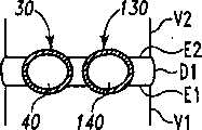
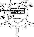
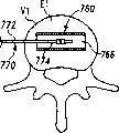
图3A和3B分别是一个脊柱节段的平面图和正视图,该脊柱节段具有一个准备容纳一对例如图1所示的可扩张设备的椎骨间隙。3A and 3B are plan and front views, respectively, of a spinal segment having a intervertebral space prepared to receive a pair of expandable devices such as that shown in FIG. 1 .
图4A和4B分别是平面图和正视图,其中图1的可扩张设备和输送装置显示为截面并放置在脊柱节段准备好的位置内。4A and 4B are plan and front views, respectively, in which the expandable device and delivery device of FIG. 1 are shown in section and placed in a prepared position of a spinal segment.
图5A和5B分别是平面图和正视图,其中可扩张设备和输送装置显示为截面并在脊柱节段准备好的位置内如图2所示一样扩张。5A and 5B are plan and front views, respectively, in which the expandable device and delivery device are shown in section and expanded as shown in FIG. 2 within the prepared position of the spinal segment.
图6A和6B分别是平面图和正视图,其中图2的扩张的可扩张设备显示为截面并位于脊柱节段准备好的位置内并输送装置已塌陷。6A and 6B are plan and front views, respectively, in which the expanded expandable device of FIG. 2 is shown in cross-section and in the prepared position of the spinal segment with the delivery device collapsed.
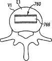
图7A和7B分别是部分截面的平面图和正视图,其中图2的扩张的可扩张设备显示为截面并位于脊柱节段准备好的位置内并输送装置已去除。7A and 7B are plan and elevation views, respectively, in partial section, with the expanded expandable device of FIG. 2 shown in section and in a prepared position at a spinal segment with the delivery device removed.
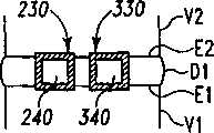
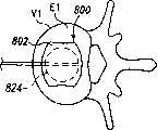
图8A和8B分别是一个脊柱节段的平面图和正视图,该脊柱节段具有一个准备容纳一对依据另一实施方案的可扩张设备的椎骨间隙。8A and 8B are plan and front views, respectively, of a spinal segment having a intervertebral space prepared to receive a pair of expandable devices according to another embodiment.
图9A和9B分别是部分截面的平面图和正视图,其中另一实施方案的塌陷的可扩张设备和输送装置显示为截面并放置在脊柱节段准备好的位置内。9A and 9B are plan and elevation views, respectively, in partial section, with another embodiment of a collapsed expandable device and delivery device shown in section and placed in a prepared position for a spinal segment.
图10A和10B分别是平面图和正视图,其中扩张的可扩张设备和输送装置显示为截面并位于脊柱节段准备好的位置内。10A and 10B are plan and front views, respectively, with the expanded expandable device and delivery device shown in cross-section and in a prepared position for a spinal segment.
图11A和11B分别是平面图和正视图,其中扩张的可扩张设备显示为截面并位于脊柱节段准备好的位置内且输送装置已塌陷。11A and 11B are plan and front views, respectively, with the expanded expandable device shown in cross-section and in the prepared position of the spinal segment with the delivery device collapsed.
图12A和12B分别是平面图和正视图,其中扩张的可扩张设备显示为截面并位于脊柱节段准备好的位置内且输送装置已去除。12A and 12B are plan and front views, respectively, with the expanded expandable device shown in cross-section and in the prepared position of the spinal segment with the delivery device removed.
图13是位于脊柱的盘间隙内的图7A和7B的可扩张设备的末端正视图。13 is an end elevation view of the expandable device of FIGS. 7A and 7B positioned within the disc space of the spine.
图14是位于脊柱的盘间隙内的图12A和12B的可扩张设备的末端正视图。14 is an end elevation view of the expandable device of FIGS. 12A and 12B positioned within the disc space of the spine.
图15是位于脊柱的盘间隙内的另一实施方案的一对可扩张设备的末端正视图。15 is an end elevational view of another embodiment of a pair of expandable devices positioned within the disc space of the spine.
图16是位于脊柱的盘间隙内的显示为截面的另一实施方案的可扩张设备的侧面正视图。Figure 16 is a side elevational view of another embodiment of an expandable device shown in section within the disc space of the spine.
图17是一截面图,示出用于插入一个或多个可扩张设备的至一脊柱的盘间隙的通道。Figure 17 is a cross-sectional view showing access to the disc space of a spine for insertion of one or more expandable devices.
图18是一截面图,示出用于插入一个或多个可扩张设备的至一脊柱的盘间隙的另一通道。Figure 18 is a cross-sectional view showing another channel for inserting one or more expandable devices into the disc space of a spine.
图19是一截面图,示出用于插入一个或多个可扩张设备的至一脊柱的盘间隙的另一通道。Fig. 19 is a cross-sectional view showing another channel for inserting one or more expandable devices into the disc space of a spine.
图20是一截面图,示出用于插入一个或多个可扩张设备的至一脊柱的盘间隙的另一通道。Fig. 20 is a cross-sectional view showing another channel for inserting one or more expandable devices into the disc space of a spine.
图21是另一实施方案可扩张设备的端视图。Figure 21 is an end view of another embodiment expandable device.
图22是处于非扩张结构中的另一实施方案可扩张设备的透视图。Figure 22 is a perspective view of another embodiment expandable device in a non-expanded configuration.
图23是处于非扩张结构中的另一实施方案可扩张设备的正视图。Figure 23 is a front view of another embodiment expandable device in a non-expanded configuration.
图24是处于扩张结构中的图23中的可扩张设备的正视图。Figure 24 is a front view of the expandable device of Figure 23 in an expanded configuration.
图25是已扩张的图24中的可扩张设备的端视图。Figure 25 is an end view of the expandable device of Figure 24 expanded.
图26是变形的脊柱节段的正视图,该脊柱节段具有一放置在盘间隙内处于非扩张状态的可扩张设备。Figure 26 is an elevational view of a deformed spinal segment with an expandable device placed in the disc space in a non-expanded state.
图27是图26中的脊柱节段,可扩张植入物在盘间隙内已扩张。Figure 27 is the spinal column segment of Figure 26 with the expandable implant expanded within the disc space.
图28是图27中的脊柱节段,第二可扩张植入物在盘间隙内已扩张。Figure 28 is the spinal column segment of Figure 27 with the second expandable implant expanded within the disc space.
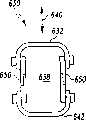
图29是处于非扩张结构中的另一实施方案可扩张设备的正视图。Figure 29 is a front view of another embodiment expandable device in a non-expanded configuration.
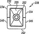
图30是处于扩张结构中的图29中的可扩张设备的正视图。Figure 30 is a front view of the expandable device of Figure 29 in an expanded configuration.
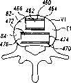
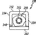
图31是图29的非扩张的可扩张设备的端视图,其中具有一输送装置的远端部分。31 is an end view of the non-expanded expandable device of FIG. 29 with a distal portion of a delivery device.
图32是图31中的可扩张设备和输送装置部分的端视图,输送装置的远端部分和可扩张设备已扩张。32 is an end view of the expandable device and delivery device portion of FIG. 31 with the distal portion of the delivery device and expandable device expanded.
图33是图32中已扩张的可扩张设备的端视图,中介元件放置在其腔内。Figure 33 is an end view of the expanded expandable device of Figure 32 with an intervening member positioned within its lumen.
图34是图33中已扩张的可扩张设备和中介元件的端视图,可扩张设备呈这样一种形式:允许由该中介元件提供主要支撑。Fig. 34 is an end view of the expanded expandable device of Fig. 33 and an intervening member, the expandable device in a form that allows primary support to be provided by the intervening member.
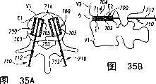
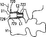
图35A和35B分别是依据另一实施方案、放置在脊柱节段的塌陷的盘间隙内、显示为截面的塌陷的可扩张设备和输送装置的平面图和正视图。35A and 35B are plan and front views, respectively, of a collapsed expandable device and delivery device, shown in section, placed within a collapsed disc space of a spinal segment, according to another embodiment.
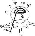
图36A和36B分别是位于该脊柱节段的恢复的盘间隙内、显示为截面的已扩张的可扩张设备和输送装置的平面图和正视图。36A and 36B are plan and front views, respectively, of the expanded expandable device and delivery device, shown in section, within the restored disc space of the spinal segment.
图37A和37B分别是位于该脊柱节段的恢复的盘间隙内、显示为截面的已扩张的可扩张设备的平面图和正视图,且输送装置被去除。37A and 37B are plan and front views, respectively, of the expanded expandable device, shown in section, within the restored disc space of the spinal segment, with the delivery device removed.
图38A和38B分别是依据另一实施方案、放置在脊柱节段的塌陷的盘间隙内、显示为截面的塌陷的可扩张设备和输送装置的平面图和正视图。38A and 38B are plan and front views, respectively, of a collapsed expandable device and delivery device, shown in section, placed within a collapsed disc space of a spinal segment, according to another embodiment.
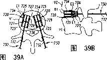
图39A和39B分别是位于该脊柱节段的恢复的盘间隙内、显示为截面的已扩张的可扩张设备和输送装置的平面图和正视图。39A and 39B are plan and front views, respectively, of the expanded expandable device and delivery device, shown in section, within the restored disc space of the spinal segment.
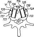
图40A和40B分别是位于该脊柱节段的恢复的盘间隙内、显示为截面的已扩张的可扩张设备的平面图和正视图,且输送装置被去除。40A and 40B are plan and front views, respectively, of the expanded expandable device, shown in section, within the restored disc space of the spinal segment, with the delivery device removed.
图41A和41B分别是依据另一实施方案、放置在脊柱节段的塌陷的盘间隙内、显示为截面的塌陷的可扩张设备和输送装置的平面图和正视图。41A and 41B are plan and front views, respectively, of a collapsed expandable device and delivery device, shown in section, placed within a collapsed disc space of a spinal segment, according to another embodiment.
图42A和42B分别是位于该脊柱节段的恢复的盘间隙内、显示为截面的已扩张的可扩张设备和输送装置的平面图和正视图。42A and 42B are plan and front views, respectively, of the expanded expandable device and delivery device, shown in section, within the restored disc space of the spinal segment.
图43A和43B分别是位于该脊柱节段的恢复的盘间隙内、显示为截面的已扩张的可扩张设备的平面图和正视图,且输送装置被去除。43A and 43B are plan and front views, respectively, of the expanded expandable device, shown in section, within the restored disc space of the spinal segment, with the delivery device removed.
图44A和44B分别是依据另一实施方案、放置在脊柱节段的塌陷的盘间隙内、显示为截面的塌陷的可扩张设备和输送装置的平面图和正视图。44A and 44B are plan and front views, respectively, of a collapsed expandable device and delivery device, shown in section, placed within a collapsed disc space of a spinal segment, according to another embodiment.
图45A和45B分别是位于该脊柱节段的恢复的盘间隙内、显示为截面的已扩张的可扩张设备和输送装置的平面图和正视图。45A and 45B are plan and front views, respectively, of the expanded expandable device and delivery device, shown in section, within the restored disc space of the spinal segment.
图46A和46B分别是位于该脊柱节段的恢复的盘间隙内、显示为截面的已扩张的可扩张设备的平面图和正视图,且输送装置被去除。46A and 46B are plan and front views, respectively, of the expanded expandable device, shown in section, within the restored disc space of the spinal segment, with the delivery device removed.
图47A和47B分别是一输送装置当远端可扩张元件处于非扩张状态和扩张状态时的正视图。47A and 47B are front views of a delivery device with the distal expandable member in a non-expanded and expanded state, respectively.
图48A和48B分别是依据另一实施方案、放置在脊柱节段的塌陷的盘间隙内、显示为截面的塌陷的可扩张设备和输送装置的平面图和正视图。48A and 48B are plan and front views, respectively, of a collapsed expandable device and delivery device, shown in section, placed within a collapsed disc space of a spinal segment, according to another embodiment.
图49A和49B分别是位于该脊柱节段的恢复的盘间隙内、显示为截面的已扩张的可扩张设备和输送装置的平面图和正视图。49A and 49B are plan and front views, respectively, of the expanded expandable device and delivery device, shown in section, within the restored disc space of the spinal segment.
图50A和50B分别是位于该脊柱节段的恢复的盘间隙内、显示为截面的已扩张的可扩张设备的平面图和正视图,且输送装置被去除。50A and 50B are plan and front views, respectively, of the expanded expandable device, shown in section, within the restored disc space of the spinal segment, with the delivery device removed.
图解实施方案的描述Description of the Illustrated Implementation
为了促进对本发明原理的理解,现提及并使用专门语言描述附图中图解的实施方案。无论如何应明确并不因此限制本发明的范围,本发明相关领域的技术人员通常会做的对所阐述的设备的任何类似的代替和进一步改进以及类似于这里阐述的任何本发明原理的进一步应用已被考虑到。In order to promote an understanding of the principles of the invention, reference will now be made and specific language will be used to describe the embodiments illustrated in the drawings. In any event, it should be expressly and without thereby limiting the scope of the present invention, any similar substitutions and further improvements to the devices described and any further application of the principles of the invention as set forth herein would normally be made by a person skilled in the art to which the invention relates has been taken into account.
已具有用于在一脊柱节段的骨结构之内和之间放置和展开可扩张设备的系统和方法。这样的系统可包含将该可扩张设备输送至手术部位并在该位置扩张该可扩张设备的装置。当放置在一椎骨间隙时,这样的扩张可分离毗邻的椎骨、恢复变形的脊柱节段、并提供一个或更多骨结构的直接和长期的支撑。Systems and methods exist for placing and deploying expandable devices within and between the bony structures of a spinal segment. Such systems may include means for delivering the expandable device to a surgical site and expanding the expandable device at that location. When placed in a intervertebral space, such expansion can separate adjacent vertebrae, restore deformed spinal segments, and provide immediate and long-term support of one or more bony structures.
依据一个实施方案,该输送装置包含一个具有一可扩张远端部分的球囊导管型装置,一个塌陷的可扩张设备围绕该可扩张的远端部分放置和固定以输送至手术部位。该输送装置可在最小侵入性外科过程中被采用以将该塌陷的或非扩张的可扩张设备输送至手术部位。紧接着该可扩张设备在手术部位的放置,该输送装置的远端部分可扩张以在手术部位展开和扩张该可扩张设备。当放置在一椎骨间隙时,可扩张设备的这种展开和扩张能够,例如,分离毗邻的椎骨以提供理想的盘间隙高度。According to one embodiment, the delivery device comprises a balloon catheter type device having an expandable distal portion around which a collapsed expandable device is placed and secured for delivery to the surgical site. The delivery device can be employed in a minimally invasive surgical procedure to deliver the collapsed or non-expanded expandable device to the surgical site. Following placement of the expandable device at the surgical site, the distal portion of the delivery device is expandable to deploy and expand the expandable device at the surgical site. When placed in a intervertebral space, such deployment and expansion of the expandable device can, for example, separate adjacent vertebrae to provide the desired disc space height.
该系统和方法可在至脊柱的最小侵入性外科通路中被采用。这样的通路包含前方的、后方的、经椎孔的、侧方的、斜的、经椎弓根的、以及至盘间隙的其它通路。这些通路在自然状态下可以是单一入口或多个入口的。该通路可至脊柱节段的任何部分,包含骶、腰、胸和颈区。使用该可扩张设备的扩张分离盘间隙去除了在该可扩张设备插入前在该盘间隙内放置一分离设备以维持盘间隙分离的需要。该系统和方法可以和任何检视系统一起使用以协助监测可扩张设备在盘间隙的放置和该设备由分离装置的扩张。合适的检视系统的例子包含荧光镜、内镜、显微镜、CT扫描、X-射线和肉眼观察系统。The system and method can be employed in minimally invasive surgical access to the spine. Such pathways include anterior, posterior, transforaminal, lateral, oblique, transpedicular, and other pathways to the disc space. These pathways may be single-entry or multi-entry in nature. The access can be to any part of the spinal segment, including the sacral, lumbar, thoracic, and cervical regions. Expanding the separation of the disc space using the expandable device removes the need to place a separation device within the disc space to maintain separation of the disc space prior to insertion of the expandable device. The system and method can be used with any inspection system to assist in monitoring placement of an expandable device in the disc space and expansion of the device by a detachment device. Examples of suitable viewing systems include fluoroscopic, endoscopic, microscope, CT scanning, X-ray and naked eye viewing systems.
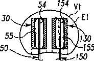
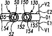
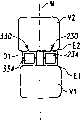
现参考图1和2,示出一个可扩张设备30的第一实施方案。在该实施方案中,可扩张设备30包含一个可放置在脊柱的盘间隙内的延长的主体,该主体包含一个可沿第一椎骨的一个终板放置的第一部分34,和一个可沿毗邻的第二椎骨的终板放置的第二部分44。第一部分34在远端引导插入端36和近端跟随端32之间延伸。第二部分44在远端引导插入端46和近端跟随端42之间延伸。在第一部分34和第二部分44之间确定一空腔40。空腔40可开口于远端36和跟随端32并在之间延伸。Referring now to Figures 1 and 2, a first embodiment of an
第一部分34可具有许多啮合元件38,第二部分44也可具有许多啮合元件48。啮合元件38、48可与椎骨的骨组织啮合,可以是例如齿、长钉、隆脊、螺纹、倒钩、刻痕、凸起、毛刺和它们的组合的形式。进一步考虑了外表面可以是光滑的,或辅助固定的或具有啮合元件。第一和第二部分34、44可进一步分别包含一个或更多开口39、49,以便于骨向内生长。The
第一部分34和第二部分44可从一非扩张结构,如图1所示,彼此移开至一扩张的结构,如图2所示。在非扩张的结构中,可扩张设备30在第一部分34和第二部分44之间具有如图1所示的高度H1。在扩张的结构中,可扩张设备30在第一部分34和第二部分44之间具有高度H2。考虑了高度H1使可扩张设备30能够被插入,例如,毗邻的椎体之间塌陷或否则变形的盘间隙内。高度H2可对应于提供一理想的毗邻椎骨间盘间隙高度所需的第一和第二部分34、44之间的间隔高度。The
可提供一输送装置50以将可扩张设备30由它的非扩张结构改变为它的扩张结构。输送装置50包含一近端轴52和一包含一可扩张元件55的远端部分54。在图示说明的实施方案中,可扩张元件55是一个可膨胀的球囊样结构,其具有如图1所示的塌陷的结构,和如图2所示的扩大的膨胀的结构。轴52可具有一个腔,可通过该腔从开口56为可扩张元件55的内腔57供给液体或材料以扩大或膨胀可扩张元件55。可扩张元件55可放置在可扩张设备30的腔40内,且可扩张元件55和可扩张设备30均处于非扩张或塌陷结构。A
当可扩张设备输送到手术部位后,可扩张元件55可被膨胀以给可扩张元件55提供扩大的结构,这样即分开可扩张设备30的第一和第二部分34、44,如图2所示。当可扩张设备30被扩张时,第一部分34和第二部分44彼此移开,和腔40的容积增大。该扩张可分离毗邻的椎骨以在毗邻的终板之间提供理想的间距和恢复盘间隙的高度。After the expandable device is delivered to the surgical site, the
合适的输送装置50的一个例子包含一个高压球囊导管。轴52可以是刚性的、半刚性的或柔性的。轴52可由金属、聚合体、或其组合制造。轴52可具有至少一个腔以使可扩张元件55可被生物相容性液体,如空气或盐水膨胀或扩大。其它实施方案考虑了轴52包含多个腔以,例如,输送骨移植物、骨生长材料、或其它合适的填充材料进入扩张的设备30的扩张的腔40内。考虑了可扩张元件55在填充材料的放置之前或同时是塌陷的。One example of a
在图示说明的实施方案中,远端部分54包含一单一的可扩张元件55,虽然也考虑了多个可扩张元件以为远端部分54提供可选择的扩张性能。例如,远端部分54可包含具有不同高度的一远端可扩张元件和一近端可扩张元件以使可扩张设备30的扩张的第一和第二部分34、44之间具有角度。在另一例子中,远端部分54可包含可被选择性扩张的一上方可扩张元件和一下方可扩张元件,以移动第一和第二部分34、44中毗邻的一个而第一和第二部分中的另一个仍保持静止。在再一个例子中,可扩张元件55单方向扩张以在扩张的方向上移动第一和第二部分34、44中毗邻的一个。In the illustrated embodiment, the
在另一实施方案中,考虑远端部分54在扩张后可由轴52切断,并在术后保持可扩张设备30于扩张状态。相应地,可扩张元件55可被骨生长材料或其它合适的骨填充材料扩张以便于骨的生长和通过扩张的设备30保持椎间隙的活动。当填充材料在可扩张元件55内适当地变硬以防止从其中延伸流动,轴52可被去除。代替地或另外地,毗邻可扩张设备55可提供一个阀门设备以阻止填充材料从其中退出。可扩张元件55可由多孔材料、可再吸收材料、或其它合适的材料制造以允许穿过扩张的设备的腔的骨生长。在再一个实施方案中,可扩张设备55由一聚合物膨胀,该聚合物可流进可扩张元件并在此后聚合以在第一和第二部分34、44之间形成一弹性核心。In another embodiment, it is contemplated that the
可扩张元件55可包含与处于扩张结构的腔40的大小和形状相匹配的大小和形状。处于扩张的结构,可扩张元件55可沿第一部分34的内壁表面在引导端36和跟随端32之间实施均匀的扩张力。如果如图2所示被构造为用于双向扩张,可扩张元件55可沿第二部分44在引导端46和跟随端42之间实施均匀的扩张力。该均匀的扩张力沿着毗邻的椎骨终板分散分离负荷以沿着可扩张设备30的长度提供均匀的分离。可扩张元件55和/或腔40可具有任何合适的总体形状包含圆锥形、截头圆锥形、球形、立方体形、球形、多角形、卵形、长圆锥形、长球形、矩形、锥形、阶梯形、狗骨形、分支形和其中的组合。
可扩张元件55可由任何能经受住为原位扩张或膨胀可扩张元件55而供给的压力的合适的材料制成。各例子包含各种聚合物材料,包含聚乙烯、对苯二酸酯、聚烯烃、聚亚安酯、尼龙、聚氯乙烯、硅或其它适合的材料。组成可扩张元件55的材料可被编织或非编织的织物材料加固。合适的加固材料的例子包含那些本质上是聚合物的或金属的材料。
现参考图3A至7B,讨论在一椎间隙内使用可扩张设备和输送装置的外科技术的一个实施例。现参考图3A和3B,示出一个脊柱节段,该脊柱节段包含一具有一下方终板E1的下方椎骨V1,一具有一上方终板E2的椎骨V2,以及其间一未分离的盘间隙D。在适当的椎间盘切除术和终板准备后,该未分离的盘间隙包含插入位置60、160用于容纳可扩张设备。插入位置60包含形成于终板E1内的容纳底座64和形成于终板E2内的容纳底座62,底座通过铰削、敲碎(scraping)、切除或砍凿中的任何一种或其组合形成。Referring now to Figures 3A through 7B, one embodiment of a surgical technique using an expandable device and delivery device within a disc space will be discussed. Referring now to Figures 3A and 3B, a spinal column segment is shown comprising a lower vertebra V1 with a lower endplate E1, a vertebra V2 with an upper endplate E2, and an unseparated disc space therebetween d. After proper discectomy and endplate preparation, this non-separated disc space contains
容纳底座62、64可被制成大小和形状匹配将放置在其中的可扩张设备的部分的外表面形状。类似的,插入位置160可包含一个形成于终板E1内的容纳底座164和形成于终板E2内的容纳底座162,底座通过铰削、敲碎、切除或砍凿中的任何一种或其组合形成。容纳底座162、164可被制成大小和形状匹配将放置在其中的可扩张设备的部分的外表面形状。在图解说明的实施方案中,容纳底座62、64、162、164具有一半圆形截面以容纳一具有圆形或弓形截面的可扩张设备。也考虑了其它形状,包含用于容纳底座的矩形和正方形截面。还进一步考虑了不形成容纳底座,以及植入物放置为直接接触终板的皮质骨或另外准备过的终板。The receiving bases 62, 64 may be sized and shaped to match the shape of the outer surface of the portion of the expandable device to be placed therein. Similarly, the
如图4A和4B所示,非扩张的可扩张设备30、130连接于输送装置50、150的塌陷的可扩张元件54、154以输送至手术部位。然后可扩张设备30、130被放置进入未分离的盘间隙D内准备好的插入位置60、160内。一种放射对比液体、盐溶液、压缩空气、或其它合适的液体或物质可通过一可操纵的注射器或泵被输送至可扩张元件55、155以为毗邻椎骨的分离提供足够的压力。随着各自的可扩张元件55、155的压力和容积增加,可扩张设备30、130逐渐被扩张。可扩张设备30、130的第一和第二部分的表面分别与准备好的终板位置62、64和终板位置162、164相接触。可扩张元件55、155内的压力持续增加以膨胀或增大可扩张元件55、155和扩张可扩张设备30、130,直到如图5A和5B所示达到理想的盘间隙D1。因此,在塌陷的可扩张设备30、130插入前分离未分离的盘间隙D并非必要。As shown in Figures 4A and 4B, the non-expandable
然后可扩张元件55、155缩小或塌陷,如图6A和6B所示。然后可扩张元件55、155可从它们各自的已扩张的可扩张设备30、130移开,如图7A和7B所示。填充材料可被堆积、塞满、放置、输送或注射进入扩张的可扩张设备30、130的腔40、140内和/或已分离的盘间隙D1内以促进融合和对毗邻各椎体的长期的支撑。The
任何合适的成骨性的材料或组分被考虑用于填充材料,包含自体移植物、异体移植物、异种移植物、去矿物质的骨和合成的和天然的骨移植物替代品,例如生物陶瓷和聚合物和骨诱导性因子。在此应用的术语成骨性材料或成骨性组分广泛的包含任何促进骨生长或愈合的材料包含自体移植物、异体移植物、异种移植物、骨移植物替代品和天然的和合成的和重组的蛋白、激素和同类的物质。Any suitable osteogenic material or component is contemplated for filling materials, including autografts, allografts, xenografts, demineralized bone and synthetic and natural bone graft substitutes, such as biological Ceramics and polymers and osteoinductive factors. The term osteogenic material or osteogenic component as used herein broadly encompasses any material that promotes bone growth or healing including autografts, allografts, xenografts, bone graft substitutes and natural and synthetic and recombinant proteins, hormones and the like.
自体移植物可使用钻、圆凿、刮匙和环锯和其它该领域外科医生熟知的工具和方法从例如髂嵴的部位获得。优选地,移植物从髂嵴使用最小侵入性供体外科手术获得。该成骨性材料也可包含骨准备终板时被外科医生刮削掉的骨。Autografts can be obtained from sites such as the iliac crest using drills, chisels, curettes and trephines and other tools and methods well known to surgeons in the art. Preferably, the graft is obtained from the iliac crest using minimally invasive donor surgery. The osteogenic material may also comprise bone scraped away by the surgeon during bone preparation of the endplate.
代替骨的结构和功能的天然的和合成的移植物替代物也被考虑用于成骨性组分。任何这样的移植物替代物已被考虑,包含例如,去矿物质的骨基质、带有骨片的去矿物质的骨基质、PMMA和其它可注射的合成的骨粘合剂、矿物质组分和生物陶瓷。一个生物陶瓷材料的大范围的集合,包含本领域公知的能够被使用以有利于该目的的BIOGLASS、羟磷灰石和磷酸钙合成物。优选的钙合成物包含生物活性玻璃、磷酸三钙和羟磷灰石。在一个实施方案中,该移植物替代物是一种包含磷酸三钙和羟磷灰石的双相的磷酸钙陶瓷。Natural and synthetic graft substitutes that replace the structure and function of bone are also contemplated for the osteogenic component. Any such graft substitutes are contemplated, including, for example, demineralized bone matrix, demineralized bone matrix with bone fragments, PMMA and other injectable synthetic bone adhesives, mineral components and bioceramics. A broad collection of bioceramic materials including BIOGLASS(R), hydroxyapatite and calcium phosphate compositions known in the art can be used to facilitate this purpose. A preferred calcium composition comprises bioactive glass, tricalcium phosphate and hydroxyapatite. In one embodiment, the graft substitute is a biphasic calcium phosphate ceramic comprising tricalcium phosphate and hydroxyapatite.
在一些实施方案中,所使用的成骨性组分可包含一种在治疗上有效的数量的刺激或诱导骨生长的骨诱导剂或生长因子或蛋白,该骨诱导剂或生长因子或蛋白位于制药上可接受的载体内的。考虑了重组的人骨形态发生蛋白(rhBMP)的骨诱导性因子,因为它们易于得到并且不引起感染性疾病的传播。该骨形态发生蛋白可以是rhBMP-2、rhBMP-4或它们的异源二聚体。然而,任何骨形态发生蛋白包含设计为BMP-1到BMP-13的骨形态发生蛋白已被考虑。In some embodiments, the osteogenic component used may comprise a therapeutically effective amount of an osteoinductive agent or growth factor or protein that stimulates or induces bone growth located at in a pharmaceutically acceptable carrier. Recombinant human bone morphogenetic protein (rhBMP) osteoinductive factors were considered because they are readily available and do not cause the spread of infectious disease. The bone morphogenetic protein may be rhBMP-2, rhBMP-4 or their heterodimers. However, any bone morphogenetic protein including those designed for BMP-1 to BMP-13 is contemplated.
用于成骨性组分的载体材料的选择基于生物相容性、生物降解能力、机械性能和接触面性能以及可扩张设备的结构。可能的载体包含硫酸钙、聚乳酸、聚酐、胶原、磷酸钙、聚合的丙烯酸酯和去矿物质的骨。该载体可以是能够输送蛋白的任何合适的载体。该载体可以是能被完全吸收入身体,例如一种由Integra LifeSciences公司出售的商品名为Helistat可吸收胶原止血剂的可吸收的胶原海绵。另一载体是一种双相磷酸钙陶瓷。陶瓷块可从Sofamor Danek Group,B.P.4-62180 Rang-du-Fliers,法国,和Bioland,132 Roud Espangne,31100 Toulouse,法国买到。成骨性因子可以任何适合的方式引入载体中。例如,载体可被浸入包含该因子的溶液中。一个优选的实施方案考虑使用Regeneration Technologies,Inc出售的OSTEOFIL异体移植物糊。该异体移植物糊可被从切割手术获得的局部自体移植物补充。The choice of carrier material for the osteogenic component is based on biocompatibility, biodegradability, mechanical and interface properties, and the structure of the expandable device. Possible carriers include calcium sulfate, polylactic acid, polyanhydrides, collagen, calcium phosphate, polymerized acrylates, and demineralized bone. The carrier can be any suitable carrier capable of delivering the protein. The carrier can be fully absorbed into the body, such as an absorbable collagen sponge sold by Integra LifeSciences under the tradename Helistat(R) Absorbable Collagen Hemostat. Another support is a biphasic calcium phosphate ceramic. Ceramic blocks are available from Sofamor Danek Group, B.P. 4-62180 Rang-du-Fliers, France, and Bioland, 132 Roud Espangne, 31100 Toulouse, France. Osteogenic factors can be introduced into the carrier in any suitable manner. For example, the support can be immersed in a solution containing the factor. A preferred embodiment contemplates the use of OSTEOFIL(R) allograft paste sold by Regeneration Technologies, Inc. This allograft paste can be supplemented by local autograft obtained from excisional surgery.
在图3A至7B的实施方案中,可扩张设备30、130可分别被输送装置50、150放射状扩张。考虑了可扩张设备30、130之一可被插入合适的盘间隙位置,然后被扩张以分离椎骨V1和V2。然后另一个可扩张设备被输送至另一插入位置,以及然后被扩张至至少接触椎骨V1和V2的终板。考虑了相同的输送装置50或150可用于输送和扩张每一设备。可选择地,每一可扩张设备30、130可被提前连接至单独的输送装置50、150。通过输送装置50、150之一位于一个已输送和扩张的设备30、130内而另一个可扩张设备30、130被输送和在另一盘间隙位置扩张,可以保持盘间隙D1的分离。In the embodiment of Figures 3A to 7B,
现参考图8A至12B,示出用于输送和在一椎间隙内扩张可扩张设备的系统和技术的另一实施方案。在图8A和8B中,示出一个脊柱节段,该脊柱节段包含具有终板E1的下方椎骨V1、具有终板E2的上方椎骨V2、和其间未分离的盘间隙D。在适当的椎间盘切除术和终板准备后,该未分离的盘空间包含插入位置260、360用于容纳可扩扎设备。插入位置260可包含形成于终板E1内的容纳底座264和形成于终板E2内的容纳底座262,底座通过如下方式中的任何一种或其组合形成:从该终板铰削、敲碎、切除或砍凿骨材料。类似的,插入位置360可包含一个形成于终板E1内的容纳底座364和形成于终板E2内的容纳底座362,底座通过铰削、敲碎、切除或砍凿中的任何一种或其组合形成。容纳底座362、364可被制成大小和形状匹配将放置在其中的可扩张设备的部分的外表面形状。在该图解的实施方案中,容纳底座262、264、362、364被构成为具有矩形截面以容纳一放置其中的可扩张设备的被对应地成形的部分。Referring now to FIGS. 8A-12B , another embodiment of systems and techniques for delivering and expanding an expandable device within a disc space is shown. In FIGS. 8A and 8B , a spinal column segment is shown comprising an inferior vertebra V1 with an endplate E1 , an upper vertebra V2 with an endplate E2 , and an unseparated disc space D therebetween. After proper discectomy and endplate preparation, this non-separated disc space contains
如图9A和9B所示,可扩张设备230、330分别沿着输送装置250、350的远端部分254、354连接于塌陷的可扩张元件255、355。然后可扩张设备230、330在未分离的盘间隙D内被放置进入相应的插入位置260、360内。一种放射对比液体、盐溶液、压缩空气、或其它合适的液体或物质可通过一可操纵的注射器或泵通过轴252、352被输送至可扩张元件255、355以为扩张可扩张设备230、330提供足够的压力和在该扩张期间分离毗邻的椎骨。随着各自的可扩张元件255、355的压力和容积增加,可扩张设备230、330逐渐被扩张,这样第一和第二部分朝向各自的椎骨V1和V2彼此移开。可扩张设备230、330在毗邻的椎骨之间在垂直方向上基本是双向可扩张的或单向可扩张的。As shown in FIGS. 9A and 9B ,
可扩张设备230的第一和第二部分的表面与准备好的终板位置262、264相接触,和可扩张设备330的第一和第二部分的表面与终板位置362、364相接触。可扩张元件255、355被增大或膨胀直到如图10A和10B所示达到理想的盘间隙D1。因此,在塌陷的可扩张设备230、330插入前分离未分离的盘间隙D并非必要。The surfaces of the first and second portions of the
然后可扩张元件255、355缩小或塌陷,如图11A和11B所示。然后远端部分254、354可从它们各自的已扩张的可扩张设备移开,如图12A和12B所示。骨生长促进材料包含骨移植物、骨移植物替代品、骨生长因子/载体、同种异体移植物、自体移植物、治疗性制剂、和其它合适的材料可被堆积、塞满、或注射进入扩张的可扩张设备230、330的各腔内和/或已分离的盘间隙D1内以促进融合和对毗邻各椎体的长期的支撑。附加或代替地,骨粘合剂,包含生物活性骨粘合剂,可被堆积、塞满、或注射进入该可扩张设备的腔内以提供对毗邻椎骨的长期支撑。The
考虑了用于可扩张设备的各种截面形状和扩张特性。在图13中,示出位于一脊柱的盘间隙内的可扩张设备30、130具有圆形截面形状。可扩张设备30、130是可放射性地扩张的,这样每一设备的高度上和侧向上的范围由于扩张而增加。在图14中,示出位于一脊柱的盘间隙内的可扩张设备230、330具有一矩形截面形状。可扩张设备230、330是可双向或单向扩张的以垂直增加每一设备的高度而侧向范围保持几乎不变。在图15中,示出位于一脊柱的盘间隙内的可扩张设备400、410具有卵圆形截面形状。可扩张设备400、410是基本上可双向或单向扩张的以垂直增加每一设备的高度而侧向范围轻微扩张或保持几乎不变。也考虑了其它截面形状,包含例如多边形、椭圆和跑道形状。Various cross-sectional shapes and expansion characteristics for expandable devices are considered. In Fig. 13, the
进一步考虑了可在一椎间隙内放置两个以上可扩张设备,以恢复椎骨间的盘空间高度。还考虑了可在一椎间隙内放置单一的可扩张设备。It is further contemplated that more than two expandable devices may be placed within a disc space to restore disc space height between vertebrae. It is also contemplated that a single expandable device may be placed within a disc space.
考虑了沿着可扩张设备的长度的各种形状。例如,在图16中,示出包含一沿其长度的锥形截面的可扩张设备420。可扩张设备420包含一具有后方末端428和前方末端426的第一部分422。可扩张设备420进一步包含一具有后方末端432和前方末端430的第二部分424。在扩张的状态下,如图16所示,后方末端428、432被放置为彼此较前方末端426、430更靠近。这个位置在可扩张设备420的上方和下方表面之间提供一锥形,当可扩张设备420由腔436内的相应成形的输送装置的远端部分扩张时,该锥形恢复该脊柱节段正常的脊柱前凸曲线。对于正常的脊柱后凸曲线,前方和后方末端之间的相对位置可反转。Various shapes along the length of the expandable device are contemplated. For example, in FIG. 16, an expandable device 420 is shown comprising a tapered cross-section along its length. Expandable device 420 includes a first portion 422 having a posterior end 428 and an anterior end 426 . The expandable device 420 further includes a second portion 424 having a posterior end 432 and an anterior end 430 . In the expanded state, as shown in FIG. 16 , the rear ends 428 , 432 are positioned closer to each other than the front ends 426 , 430 . This position provides a taper between the superior and inferior surfaces of the expandable device 420 that restores the spinal segment to normal when the expandable device 420 is expanded by the distal portion of a correspondingly shaped delivery device within the lumen 436. lordotic curve. For a normal kyphotic curve, the relative position between the anterior and posterior extremities may be reversed.
为了椎骨间应用,考虑了各种至脊柱的盘间隙的通道。在图17中,使用一前方通道,在其内形成插入位置70、72以容纳一对并排的可扩张设备30、130。其它实施方案考虑一个插入单一的可扩张设备的前方通道,该可扩张设备定大小和形状为双侧支撑毗邻的椎骨。For intervertebral applications, various accesses to the disc space of the spine are contemplated. In Fig. 17, a frontal channel is used in which insertion locations 70, 72 are formed to accommodate a pair of side-by-side
在图18中,显示了一个后方通道,在该后方通道内植入物容纳位置74、76在盘间隙内在后部形成。可扩张设备30、130以一塌陷的状态从一后方通道插入该植入物容纳位置,此后被扩张以分离盘间隙。通过以一塌陷的状态将可扩张设备30、130插入一后方通道,该通道内收缩至盘间隙的神经根和肌肉的数量被最小化。而且,在盘间隙内不需要单独的分离器或其它设备,该分离器或其它设备将在盘间隙内占据空间,目的是在植入物插入期间保持分离。这样的分离器还可在通向植入物插入位置的解剖空间内占据空间。去除分离器在盘间隙内为已扩张的可扩张设备的占据提供了额外的空间。In Fig. 18, a posterior channel is shown in which implant receiving locations 74, 76 are formed posteriorly within the disc space. The
在图19中,显示了一个后侧方通道,在该后侧方通道内插入位置78、80在盘间隙内倾斜形成。可扩张设备440、450以一塌陷的状态从一后侧方通道插入该植入物容纳位置,此后被扩张以分离盘间隙。可扩张设备440、450在盘间隙内形成一V形,该V形的尖端指向前方。通过以一塌陷的状态将可扩张设备440、450插入一后侧方通道,该通道沿着该椎骨的后部中心远离脊髓区域移动。并且,在此过程中不需要将被放置在盘间隙内的单独的分离器或其它设备,在盘间隙内为已扩张的可扩张设备的占据提供了额外的空间。In Fig. 19, a rear side channel is shown in which the
在图20中,显示了一个侧方通道,在该侧方通道内形成侧向彼此隔开穿过盘空间的插入位置82、84。可扩张设备460、470以一塌陷的状态从一侧方通道插入该插入位置,此后被扩张以分离盘间隙。通过以一塌陷的状态将可扩张设备460、470插入一侧方通道,神经根和肌肉收缩的数量和在胸廓过程中肋架的扩张一起被最小化。而且,在盘间隙内不需要单独的分离器或其它设备以保持分离,该分离器或其它设备将在盘间隙内和至盘间隙的通道内占据空间。其它的实施方案考虑了一个侧方通道,在其内插入一单一的可扩张设备,该可扩张设备定大小和形状为提供对毗邻椎骨的前方和后方支撑。In Fig. 20, a side channel is shown in which
在图20中,在前部放置的可扩张设备460包含一个主体462,该主体462在一引导插入端464和一相对的跟随端466之间延伸。在后部放置的可扩张设备470包含一主体472,该主体472在一引导插入端474和一相对的跟随端476之间延伸。在各自的引导和跟随端之间的主体462的长度可短于主体472的长度,以在盘间隙内容纳可扩张设备460的前部放置。In FIG. 20 , an anteriorly positioned
此处考虑的可扩张设备可以各种形式被提供。例如,如图21所示,可扩张设备的第一和第二部分沿着第一和第二部分交迭的侧壁可以是可调地连接。可扩张设备480包含类似于上述可扩张设备30的一第一部分482和一第二部分492。第一部分432包含相对的侧壁484、485,和第二部分492包含相对的侧壁494、495。第一部分482和第二部分492确定了其间的一个腔488,输送装置50的可扩张元件55可被放置在该腔中。The expandable devices contemplated herein may be provided in a variety of forms. For example, as shown in FIG. 21, the first and second portions of the expandable device may be adjustably connected along overlapping sidewalls of the first and second portions. Expandable device 480 includes a first portion 482 and a second portion 492 similar to
毗邻的侧壁484、494包含许多啮合彼此的互相交叉的齿,和毗邻的侧壁485、495包含许多啮合彼此的互相交叉的齿。在图解说明的实施方案中,该互相交叉的齿沿侧壁484、485、494、495的长度的全部或部分延伸。该互相交叉的齿可使第一和第二部分482、492紧接着腔488内的可扩张元件55的扩张如箭头490所指示单向或双向彼此移开。该互相交叉的齿可包含一抵抗或阻止第一和第二部分在扩张后朝向彼此移动的棘齿结构。Adjacent side walls 484, 494 include a plurality of interdigitated teeth that engage each other, and adjacent side walls 485, 495 include a plurality of interdigitated teeth that engage each other. In the illustrated embodiment, the interdigitated teeth extend along all or part of the length of the side walls 484 , 485 , 494 , 495 . The interdigitated teeth allow first and second portions 482 , 492 to move away from each other in either one or both directions as indicated by arrow 490 following expansion of
可扩张设备480在分离后立即保持对分离的椎骨的支撑,即使在从腔488去除可扩张元件55之后。该互相交叉的齿还确定多个第一和第二部分482、492之间的扩张的或分离的位置,该多个扩张的或分离的位置提供可由单个可扩张设备480实现的各分离高度。因此,可扩张设备480在垂直方向上是可塌陷的以便于由输送装置插入一塌陷的盘间隙,和此后在垂直方向上是可扩张的以分离该盘间隙和保持手术后的分离。The expandable device 480 maintains support for the separated vertebrae immediately after separation, even after the
在另一实施例中,该可扩张设备可由形状记忆材料或可塑材料制成,该可扩张设备是非扩张的或塌陷的用于在插入前放置在输送装置上。一旦插入脊柱的盘间隙内,该设备可通过输送装置的膨胀或扩大放射状地扩张以呈现和保持一扩张的结构。该可扩张设备的扩张可通过温度变化、化学变化、或由于输送装置50的可扩张元件55膨胀或扩大的力导致的变化而实现。In another embodiment, the expandable device may be made of a shape memory material or a moldable material, the expandable device being non-expandable or collapsed for placement on the delivery device prior to insertion. Once inserted into the disc space of the spine, the device can be expanded radially by inflation or enlargement of the delivery device to assume and maintain an expanded configuration. Expansion of the expandable device may be accomplished through temperature changes, chemical changes, or changes due to the force of expansion or expansion of the
例如,图22示出可扩张设备530包含一主体538,该主体538确定一在近端534和远端536之间延伸的内腔532。主体538包含多个在其周围的部分542,每一该部分确定一个伸长的弹性开口544。毗邻片段542通过合叶546相互连接。主体538由足够可塑或可成形材料制成,以使一旦施加如箭头540指示的放射状扩张力,弹性开口544可增大和合页546可伸展以允许片段542彼此移开,增大内腔532,从而分离毗邻椎骨。For example, FIG. 22 shows an
在另一个实施例中,该可扩张设备可包含第一机械结构,该第一机械结构允许用于使用输送装置插入该设备的塌陷状况。在插入后,紧接输送装置远端部分的膨胀或扩大,该设备可被机械调整以在手术部位呈现一扩张的状况。这样的可扩张设备的例子包含那些由金属丝网制成的,和具有由机械联接连接的第一和第二部分的设备,如图23-25所示。In another embodiment, the expandable device may comprise a first mechanical structure that allows for a collapsed condition for insertion of the device using a delivery device. Following insertion, following inflation or enlargement of the distal portion of the delivery device, the device may be mechanically adjusted to assume an expanded condition at the surgical site. Examples of such expandable devices include those made of wire mesh and having first and second portions connected by a mechanical linkage, as shown in Figures 23-25.
在图23-25中,设备630包含一第一部分632和一第二部分642。联接650可移动地将第一和第二部分632、642彼此连接。联接650包含可枢转地彼此连接的第一和第二元件652、654。元件652、654每一个都包含一放置在第一部分632的凹槽634中各自的一个内的第一末端,和相对的放置在第二部分642的凹槽644中各自的一个内的第二末端。元件650、652的末端可包含一结构,该结构与沿着各自的凹槽634、644形成的棘齿表面互相交叉。在图23所示的非扩张结构中,元件652、654的末端放置在各自的凹槽634、644的外侧端。In FIGS. 23-25 ,
当第一和第二部分632、642被在空腔638中使用可扩张元件55双向互相移开时,如箭头640所示,则元件650、652的末端沿每个各自的第一和第二部分632、642的凹槽634、644纵向移向另一个,如图24所示。刚性元件652、654将第一和第二部分632、642相互移开,并且沿凹槽634、644啮合棘齿表面,以在第一和第二部分632、642间保持扩张的或分离的位置,如图24和25所示。因此可扩张设备是垂直可塌陷的,以便于使用输送装置插入塌陷的盘间隙,并且此后是垂直可扩张的以分离盘间隙和在手术后保持分离。When the first and
现参考图26-28,示出使用这里说明的可扩张设备用于恢复侧凸脊柱节段的一个技术的各种步骤。图26-28将参考可扩张设备30、330被说明,应明确这里说明的其他可扩张设备实施例也可应用在这个技术中。在图26中,脊柱节段包含分别在终板E1和E2间具有变形的或塌陷的盘D的椎骨V1和椎骨V2。可扩张设备230被以非扩张状态放置在脊柱中线M侧的盘间隙D中,脊柱节段对该脊柱中线M是凹面弯曲的。Referring now to FIGS. 26-28 , there are shown various steps in one technique for restoring a scoliotic spinal segment using the expandable devices described herein. Figures 26-28 will be described with reference to
在图27中,可扩张设备例如使用输送装置250的可扩张元件255来扩张,以使终板E1和E2相互移开,并进入更平行或自然的位置,得到恢复的盘间隙D1。在图28中,第二可扩张设备330被放置在脊柱中线M的相对侧的盘间隙D1,并扩张以提供平衡的双面脊柱节段的支撑。In Fig. 27, the expandable device is expanded, eg, using
对于多水平侧凸矫正过程,使用一个或多个另外的放置在其他椎骨水平的盘间隙中的可扩张设备230恢复理想的脊柱节段也被考虑。在可扩张设备230、330扩张后,空腔可被填充材料填充,譬如移植骨、移植骨代用品、和用于促进愈合的骨促进材料。若想要保持一个或多个恢复的椎骨水平的运动,则运动保留设备可被插入可扩张设备230、330的空腔,如下面进一步的说明。For multi-level scoliosis correction procedures, restoration of the ideal spinal segment using one or more additional
图29-30提供可扩张设备230、330的实施方案的正视图。可扩张设备230包含第一部分232和第二部分242,第一部分232和第二部分242限定其中的空腔240。第一部分232包含侧壁234,每个侧壁包含臂235。凹槽238沿臂235的一端形成。臂235包含沿凹槽238延伸的啮合表面23。第二部分242同样地包含侧壁244,每个侧壁包含臂245和凹槽248,臂245被容纳在凹槽238中,以及臂235被容纳在凹槽248中。臂245包含沿此延伸的啮合表面247,该啮合表面247与毗邻的第一部分232的臂235的啮合表面237相啮合。29-30 provide front views of embodiments of expandable devices 230,330. The
在图29和31中,可扩张设备230被显示处于塌陷状态,在第二部分240的臂245完全进入毗邻第一部分230的凹槽238的情况下。非扩张状态的可扩张元件255被放置空腔240中,以及可扩张设备230非扩张。在图30和32中,可扩张元件255被扩张以互相移开第一和第二部分232、242至一个扩张的结构。啮合表面237、247可互相交叉和相互啮合,以维持可扩张设备230处于扩张状态,即使压缩负荷被施加至第一和第二部分232、242。啮合表面237、247可具有棘齿的或其它适当的结构,该结构允许第一和第二部分232、242互相离开的运动,而阻挡或阻止第一和第二部分232、242互相靠近的运动。In FIGS. 29 and 31 , the
在图33中,可扩展元件255被去除,以及运动保留设备270被放置在扩张的可扩张设备230的空腔240中。运动保留设备270可包括弹性核272和可沿第一和第二部分232、242的各自部分放置的上、下板274、276。在运动保留设备270被放置在空腔240中情况时,在第一和第二部分232、242的啮合表面之间的接触被消除,以使负荷由弹性核272支撑。例如,臂235、245中一个或两个和/或啮合表面237、247可被去除,或随时间的过去而被吸收。在第一和第二部分232、242之间的压缩负荷支撑能力的去除允许压缩负荷由弹性核272支撑。In FIG. 33 ,
弹性核272允许被压缩的毗邻椎骨间的运动,同时维持毗邻椎骨终板间的理想放置。通过去除负荷支撑臂和/或在第一和第二部分232、242间的啮合表面237、247,可实现在第一和第二部分232、242之间由刚性负荷支撑臂235、245支撑的负荷至弹性核272的转移。在一个实施方案中,通过在第一和第二部分232、242之间的刚性负荷支撑的体内降解可实现负荷去除。例如,刚性负荷支撑臂235、245,或整个第一和第二部分232、242可由生物可再吸收多聚物或其他生物可降解的或可再吸收的材料制造。The resilient core 272 allows movement between the compressed adjacent vertebrae while maintaining ideal placement between the endplates of the adjacent vertebrae. By removing the load support arms and/or the engaging
在一个实施例,通过将可聚合的多聚物注射入可扩张元件255,弹性核272可被形成在手术部位。通过将第一和第二部分232、242互相移开并与毗邻椎骨终板接触,多聚物使可扩张元件255扩张和恢复盘间隙高度。在聚合后,轴252可被分离,和可扩张元件255保留在可扩张设备230的空腔中。可扩张元件255可具有与在第一和第二部分232、242之间的空腔相匹配的大小和形状,以沿其整个长度提供弹性负荷支撑。在使用这种类型弹性核的实施方案中,设备20不需要具备在第一和第二部分232、242之间的刚性负荷支撑臂。In one embodiment, elastic core 272 may be formed at the surgical site by injecting a polymerizable polymer into
图35A和35B分别是放置在脊柱V1和V2之间的塌陷的盘间隙D内、另一实施方案的一对塌陷的可扩张设备700和相关的输送装置710的平面图和正视图。塌陷的或非扩张的可扩张设备700围绕各自的位于输送装置710的远端的非扩张的可扩张元件714固定,以输送至塌陷的盘间隙D。在图解说明实施方案中,从后通道进入盘间隙D,尽管也考虑了其他通道。可扩张设备700包含在相对侧703、705之间的宽度。35A and 35B are plan and front views, respectively, of another embodiment of a pair of collapsed
图36A和36B分别是平面图和正视图,其中可扩张设备700由通过输送装置710的轴712输送的液体扩张。在已扩张状况下,可扩张设备700的下和上表面702、704作用于毗邻椎骨终板E1、E2上以分离椎骨V1、V2,并提供恢复的盘间隙D1。在扩张期间和扩张后,可扩张设备700在相对侧703、705之间的宽度几乎保持不变。因此设备700是垂直可扩张的以增加它们的高度而它们的宽度保持恒定。36A and 36B are plan and front views, respectively, of
可扩张设备700沿其长度在前和后端间是逐渐变细的。在已图解说明的实施方案中,后端包含第一高度708,以及前端包含大于第一高度708的第二高度709。逐渐变小的高度在终板E1、E2间提供一可能需要的理想角度。还考虑了设备700可在前端逐渐变细。The
图37A和37B分别是平面图和正视图,其中已扩张的可扩张设备700位于脊柱节段已恢复的盘间隙D1内,并且输送装置710被从可扩张设备700的空腔706中去除。用于融合或在毗邻椎骨间维持运动的填充材料可被放置在空腔706中。37A and 37B are plan and front views, respectively, with the expanded
图38A和38B分别是放置在脊柱V1和V2之间的塌陷的盘间隙D内、另一实施方案的一对塌陷的可扩张设备720和相关的输送装置730的平面图和正视图。塌陷的或非扩张的可扩张设备720围绕各自的位于输送装置730的远端的非扩张的可扩张元件734、736安装,以输送至塌陷的盘间隙D。可扩张设备720每个包含后方部分723和前方部分725,以及在相对侧727、729之间的宽度。可扩张设备720的高度和宽度在其塌陷的或非扩张状态中沿部分723、725基本上是一致的。38A and 38B are plan and front views, respectively, of another embodiment of a pair of collapsed
图39A和39B分别是平面图和正视图,其中可扩张设备720由通过输送装置730的轴732输送的液体扩张。在已扩张状况下,可扩张设备720的后方和前方部分723、725作用于毗邻椎骨终板E1、E2上以分离椎骨V1、V2,并提供恢复的盘间隙D1。在扩张期间和扩张后,可扩张设备720在相对侧727、729之间的宽度几乎保持不变。因此设备720是垂直可扩张的宽度保持恒定。39A and 39B are plan and front views, respectively, of
可扩张设备720在前路部分725和后路部分723之间的高度是阶梯变化的,以为已扩张的可扩张设备720提供较大的前方高度。阶梯变化的的高度在终板E1、E2间提供一理想角度。还考虑了设备720在前方高度上可以是向下阶梯变化的。为便于这个阶梯样分离,输送装置730可具有前方可扩张元件734和后方可扩张元件736。可扩张元件734、736可在其扩张的结构中具有不同高度,该高度与放置可扩张元件734、736的前方和后方部分725、723的各自的扩张的高度相一致。The height of the
图40A和40B分别是平面图和正视图,其中已扩张的可扩张设备720位于脊柱节段恢复的盘间隙D1中,并且输送装置730被从可扩张设备720的空腔726中去除。用于融合或在毗邻椎骨间维持运动的填充材料可被放置在空腔726中。40A and 40B are plan and front views, respectively, with expanded
图41A和41B分别是放置在脊柱V1和V2之间的塌陷的盘间隙D内、另一实施方案的一对塌陷的可扩张设备740和相关的输送装置750的平面图和正视图。塌陷的或非扩张的可扩张设备740围绕各自的位于输送装置750的远端的非扩张的可扩张元件754安装,以输送至塌陷的盘间隙D。在塌陷状态中,可扩张设备740包含一凸面弯曲的前壁742和凹面弯曲的后壁744。壁742、744形成香蕉形或肾形,该形状便于从单一通道将可扩张设备740放置在盘间隙中用于对椎骨V1和V2的双侧支撑。41A and 41B are plan and front views, respectively, of another embodiment of a pair of collapsed
图42A和42B分别是平面图和正视图,其中可扩张设备740由通过输送装置750的轴752输送的液体扩张。在已扩张状况下,可扩张设备740的上方和下方部分747、748作用于毗邻椎骨终板E1、E2以分离椎骨V1、V2,并提供恢复的盘间隙D1。可扩张设备740的扩张可引起后壁744向后移动,以使在已扩张状况下,后壁744基本上是线性的,以使可扩张设备740具有D形。42A and 42B are plan and front views, respectively, of
可扩张设备740包含凸面弯曲的前壁742,该壁742便于可扩张设备740沿着弯曲的插入路径的放置,在该路径中前壁742与终板E1、E2的弯曲前部的曲线相一致。在已图解说明的实施方案中,可扩张设备740被放置在盘间隙D的前半部分。可扩张元件754在被扩张时可具有与D形内腔746相一致的形状。The
图43A和43B分别是平面图和正视图,其中已扩张的可扩张设备740位于脊柱节段恢复的盘间隙D1中,并且输送装置750被从可扩张设备740的空腔746中去除。用于融合或在毗邻椎骨间维持运动的填充材料可被放置在空腔746中。43A and 43B are plan and front views, respectively, with expanded
图44A和44B分别是放置在脊柱V1和V2之间的塌陷的盘间隙D内、另一实施方案的一对塌陷的可扩张设备760和相关的输送装置770的平面图和正视图。塌陷的或非扩张的可扩张设备760围绕各自的位于输送装置770的远端的非扩张的可扩张元件774安装,以从侧通道中输送至塌陷的盘间隙D。可扩张设备760包含沿可扩张元件774的相对侧啮合的及可毗邻各自终板E1和E2放置的第一部分762和第二部分764。44A and 44B are plan and front views, respectively, of another embodiment of a pair of collapsed
图45A和45B分别是平面图和正视图,其中可扩张设备760通过操作输送装置770的轴772以扩张可扩张元件774而被扩张。在已扩张状况下,可扩张设备760的第一和第二部分762、764作用于毗邻椎骨终板E1、E2以分离椎骨V1、V2,并提供恢复的盘间隙D1。45A and 45B are plan and front views, respectively, in which
图46A和46B分别是平面图和正视图,其中已扩张的可扩张设备760位于脊柱节段恢复的盘间隙D1中,并且输送装置770被从可扩张设备760的空腔766中去除。用于融合或在毗邻椎骨间维持运动的填充材料可被放置在空腔766中。46A and 46B are plan and front views, respectively, with expanded
输送装置770的进一步的细节被提供在图47A和47B中。轴772包含近端手柄部分773和延伸通过可扩张元件774的远端部分776。可扩张元件774包含第一枢转连接778和第二枢转连接780。连接778、780每一个包含一中间枢转点,该中间枢转点与远端部分776啮合并是可移动。连接778、780进一步包含连接在其上和下端的分离元件782、784。Further details of
远端部分776被连接至连接778、780,以使当轴772如图47A所示使用手柄部分773绕其轴旋转时,连接778、780的枢转中间部分被拉向彼此以移动分离元件782、784彼此离开,如图47B所示。当被放置在可扩张元件的空腔中时,分离元件782、784接触可扩张设备毗邻的部分,以扩张该可扩张设备和分离盘间隙。当获得理想的分离时,通过以相反方向旋转轴772和朝向彼此移动分离元件782、784,可扩张设备770可从移植物中去除。The
图48A和48B分别是放置在椎骨V1和V2之间塌陷的盘间隙D内的另一实施方案的塌陷的可扩张设备800和相关输送装置820的平面图和正视图。该塌陷的或非扩张的可扩张设备800围绕位于输送装置800远端的非扩张的可扩张元件824安装,用于在一前方通道内输送至塌陷的盘间隙D。可扩张设备800包含一第一部分802和一第二部分804,该第一和第二部分沿着可扩张元件824的相对的两侧啮合并可毗邻终板E1和E2中各自的一个放置。48A and 48B are plan and front views, respectively, of another embodiment of a collapsed
第一和第二部分802、804包含占据了毗邻椎骨终板相当大部分的大小和形状,以为负荷的分散提供大的表面面积。在一个实施方案中,第一和第二部分占据椎骨终板的一半以上,并包含一个穿越脊柱中线延伸的宽度以提供对毗邻椎骨的双侧支撑。第一和第二部分802、804每一个都包含如图示的D形、卵圆形、圆形、矩形、或具有圆形前和后壁的矩形的各终板接触表面。The first and
第一部分802包含多个从那延伸的啮合元件806,该啮合元件朝向毗邻的椎骨终板E2延伸。类似地,第二部分804包含多个从那向终板E1延伸的啮合元件806。在非扩张结构中,第一和第二部分802、804包含一个高度,该高度允许啮合元件806、808沿着终板E1、E2移动而不啮合终板和不妨碍设备800在盘间隙内的放置。The
图49A和49B分别是平面图和正视图,其中可扩张设备800被增大或膨胀的可扩张元件824扩张。在该扩张的状态下,可扩张设备的第一和第二部分802、804作用于毗邻的椎骨终板E1、E2上,以分离椎骨V1、V2和提供恢复的盘间隙D1。并且,啮合元件806、808被驱动进入毗邻椎骨终板E1、E2以获得第一和第二部分802、804至椎骨V2、V1的固定。然后可扩张元件824可缩小和从可扩张设备800移开。第一和第二部分802、804之间的相对位置可由第一和第二部分802、804与各自的椎骨终板的啮合来保持。考虑了第一和第二部分802、804可如上述由延伸其间的啮合元件相互连接,虽然第一和第二部分802、804的扩张或分离也可仅由它们与各自的椎骨终板的固定来保持。49A and 49B are plan and front views, respectively, of
图50A和50B分别是平面图和正视图,其中扩张的可扩张设备800位于脊柱节段的恢复的盘间隙D1内,以及输送装置820从可扩张设备800的腔内被去除。然后可在第一和第二部分802、804之间的空隙或腔内放置一运动保留设备810,如箭头818所指示的。该动作保护设备810可以如上所讨论的是一个弹性的核。在一个实施方案中,该弹性核812包含上方和下方凸面弯曲的表面814、816,该表面接触第一和第二部分802、804中毗邻的一个,以便于毗邻椎骨间关于弹性核812的运动。50A and 50B are plan and front views, respectively, with the expanded
于是脊柱的负荷可被传递至运动保留设备810以允许在那被支撑的脊柱节段的运动。传递脊柱负荷可通过在第一和第二部分802、804之间延伸的负荷支撑元件或啮合元件的移动来完成,或通过朝向彼此移动第一和第二部分802、804来完成,如上面讨论的。进一步考虑运动保留设备810可以一减小尺寸的结构插在第一和第二部分802、804之间,以及此后释放或扩张以接触毗邻的第一和第二部分802、804。进一步考虑椎骨V1、V2可被过度-分离以容纳运动包护设备810的插入,然后被压缩使第一和第二部分802、804与此接触。The load of the spine may then be transferred to the
仍然另一个实施方案中,可扩张元件824包含一运动保留设备810的外壳。在该实施方案中,可扩张元件824被一种适当的可聚合的材料膨胀。该可聚合的材料可以在原位固化,以及孔口或轴822被切断或去除,这样可扩张元件824的弹性核在手术后保留在第一和第二部分802、804之间。In yet another embodiment, the
此处的可扩张设备可具有一个或更多开口、窗、或其它结构,其允许它的内腔和毗邻的骨结构之间的连通以便于骨向内生长。该可扩张设备可包含一个单一的腔或多个腔。进一步考虑了该可扩张设备可具有支撑机构,该支撑机构可放置在腔内以保持或协助保持该设备的扩张的状态。The expandable device herein may have one or more openings, windows, or other structures that allow communication between its lumen and adjacent bony structures to facilitate bony ingrowth. The expandable device may comprise a single lumen or multiple lumens. It is further contemplated that the expandable device may have a support mechanism that may be placed within the lumen to maintain or assist in maintaining the expanded state of the device.
此处讨论的可扩张设备可由任何生物相容性材料制成,该生物相容性材料包含金属、聚合物和合成物。金属的例子包含钛和钛合金;镍钛合金;不锈钢;和钴铬合金。聚合物的例子包含例如聚芳醚酮;聚醚醚酮;聚砜;聚烯烃;聚乙烯;酪氨酸基聚碳酸酯;聚酯;聚交酯;聚乙醇酸交酯(polyglicolide);聚原酸酯;聚磷腈;聚羟基丁酸酯;和聚羟基戊酸酯。合成物的例子包含例如碳填充合成物;羟磷灰石填充合成物;生物活性玻璃填充合成物;和皮质骨片填充合成物。The expandable devices discussed herein can be made from any biocompatible material, including metals, polymers, and composites. Examples of metals include titanium and titanium alloys; nickel titanium alloys; stainless steel; and cobalt chromium alloys. Examples of polymers include, for example, polyaryletherketone; polyetheretherketone; polysulfone; polyolefin; polyethylene; tyrosine-based polycarbonate; polyester; polylactide; polyglycolide; polyglycolide; Orthoesters; polyphosphazenes; polyhydroxybutyrates; and polyhydroxyvalerates. Examples of composites include, for example, carbon-filled composites; hydroxyapatite-filled composites; bioactive glass-filled composites; and cortical bone chip-filled composites.
虽然本发明在附图和前述中被详细图示解释和说明,但图示解释和说明的本发明被认为是说明性的和不具限制特性,在本发明的宗旨范围内的所有变化和改良都要求被保护。While the invention has been illustrated and described in detail in the drawings and foregoing description, the invention illustrated and described is to be considered as illustrative and not restrictive in character and all changes and modifications within the spirit of the invention are considered claim to be protected.
Claims (71)
Applications Claiming Priority (2)
| Application Number | Priority Date | Filing Date | Title |
|---|---|---|---|
| US42808102P | 2002-11-21 | 2002-11-21 | |
| US60/428,081 | 2002-11-21 |
Publications (1)
| Publication Number | Publication Date |
|---|---|
| CN1756517Atrue CN1756517A (en) | 2006-04-05 |
Family
ID=32393346
Family Applications (2)
| Application Number | Title | Priority Date | Filing Date |
|---|---|---|---|
| CNA2003801086349APendingCN1756517A (en) | 2002-11-21 | 2003-11-19 | Systems and methods for interbody spinal stabilization using an expandable device |
| CNA2003801039066APendingCN1713863A (en) | 2002-11-21 | 2003-11-19 | Systems and techniques for interbody spinal stabilization with expandable devices |
Family Applications After (1)
| Application Number | Title | Priority Date | Filing Date |
|---|---|---|---|
| CNA2003801039066APendingCN1713863A (en) | 2002-11-21 | 2003-11-19 | Systems and techniques for interbody spinal stabilization with expandable devices |
Country Status (9)
| Country | Link |
|---|---|
| US (1) | US20040133280A1 (en) |
| EP (2) | EP1562523A1 (en) |
| JP (2) | JP2006507090A (en) |
| CN (2) | CN1756517A (en) |
| AT (1) | ATE395885T1 (en) |
| AU (2) | AU2003298670A1 (en) |
| CA (2) | CA2506624A1 (en) |
| DE (1) | DE60321225D1 (en) |
| WO (1) | WO2004047691A1 (en) |
Cited By (3)
| Publication number | Priority date | Publication date | Assignee | Title |
|---|---|---|---|---|
| CN103830023A (en)* | 2012-11-26 | 2014-06-04 | 思邦科技脊柱智慧公司 | Expandable cage for intracorporeal fusion of lumbar vertebrae |
| CN104936555A (en)* | 2013-01-24 | 2015-09-23 | 华沙整形外科股份有限公司 | Expandable spinal implant system and method |
| CN110141340A (en)* | 2019-04-01 | 2019-08-20 | 上海中医药大学附属龙华医院 | A spinal fracture collapse and expansion device |
Families Citing this family (363)
| Publication number | Priority date | Publication date | Assignee | Title |
|---|---|---|---|---|
| US20050245937A1 (en)* | 2004-04-28 | 2005-11-03 | St. Francis Medical Technologies, Inc. | System and method for insertion of an interspinous process implant that is rotatable in order to retain the implant relative to the spinous processes |
| US6068630A (en) | 1997-01-02 | 2000-05-30 | St. Francis Medical Technologies, Inc. | Spine distraction implant |
| US20080039859A1 (en) | 1997-01-02 | 2008-02-14 | Zucherman James F | Spine distraction implant and method |
| US8128661B2 (en) | 1997-01-02 | 2012-03-06 | Kyphon Sarl | Interspinous process distraction system and method with positionable wing and method |
| US7959652B2 (en) | 2005-04-18 | 2011-06-14 | Kyphon Sarl | Interspinous process implant having deployable wings and method of implantation |
| US7306628B2 (en) | 2002-10-29 | 2007-12-11 | St. Francis Medical Technologies | Interspinous process apparatus and method with a selectably expandable spacer |
| US20080086212A1 (en) | 1997-01-02 | 2008-04-10 | St. Francis Medical Technologies, Inc. | Spine distraction implant |
| US7201751B2 (en) | 1997-01-02 | 2007-04-10 | St. Francis Medical Technologies, Inc. | Supplemental spine fixation device |
| US20050228397A1 (en)* | 1998-08-14 | 2005-10-13 | Malandain Hugues F | Cavity filling device |
| US20050049707A1 (en)* | 2003-08-29 | 2005-03-03 | Ferree Bret A. | Cemented artificial disc replacements |
| US6805695B2 (en) | 2000-04-04 | 2004-10-19 | Spinalabs, Llc | Devices and methods for annular repair of intervertebral discs |
| US20020026244A1 (en)* | 2000-08-30 | 2002-02-28 | Trieu Hai H. | Intervertebral disc nucleus implants and methods |
| US8388684B2 (en) | 2002-05-23 | 2013-03-05 | Pioneer Signal Technology, Inc. | Artificial disc device |
| US6793678B2 (en) | 2002-06-27 | 2004-09-21 | Depuy Acromed, Inc. | Prosthetic intervertebral motion disc having dampening |
| EP1542626B1 (en) | 2002-08-15 | 2012-09-26 | Synthes GmbH | Controlled artificial intervertebral disc implant |
| CA2495404C (en) | 2002-08-15 | 2011-05-03 | Justin K. Coppes | Intervertebral disc implant |
| FR2844179B1 (en) | 2002-09-10 | 2004-12-03 | Jean Taylor | POSTERIOR VERTEBRAL SUPPORT KIT |
| US7549999B2 (en) | 2003-05-22 | 2009-06-23 | Kyphon Sarl | Interspinous process distraction implant and method of implantation |
| US7833246B2 (en) | 2002-10-29 | 2010-11-16 | Kyphon SÀRL | Interspinous process and sacrum implant and method |
| US7909853B2 (en) | 2004-09-23 | 2011-03-22 | Kyphon Sarl | Interspinous process implant including a binder and method of implantation |
| US8147548B2 (en) | 2005-03-21 | 2012-04-03 | Kyphon Sarl | Interspinous process implant having a thread-shaped wing and method of implantation |
| US8070778B2 (en) | 2003-05-22 | 2011-12-06 | Kyphon Sarl | Interspinous process implant with slide-in distraction piece and method of implantation |
| US7931674B2 (en) | 2005-03-21 | 2011-04-26 | Kyphon Sarl | Interspinous process implant having deployable wing and method of implantation |
| US20080021468A1 (en)* | 2002-10-29 | 2008-01-24 | Zucherman James F | Interspinous process implants and methods of use |
| US8048117B2 (en) | 2003-05-22 | 2011-11-01 | Kyphon Sarl | Interspinous process implant and method of implantation |
| WO2004047689A1 (en)* | 2002-11-21 | 2004-06-10 | Sdgi Holdings, Inc. | Systems and techniques for intravertebral spinal stablization with expandable devices |
| US7335203B2 (en) | 2003-02-12 | 2008-02-26 | Kyphon Inc. | System and method for immobilizing adjacent spinous processes |
| AU2004212942A1 (en) | 2003-02-14 | 2004-09-02 | Depuy Spine, Inc. | In-situ formed intervertebral fusion device |
| WO2004084742A1 (en) | 2003-03-24 | 2004-10-07 | Theken Surgical Llc | Spinal implant adjustment device |
| US6969405B2 (en)* | 2003-04-23 | 2005-11-29 | Loubert Suddaby | Inflatable intervertebral disc replacement prosthesis |
| US20050010297A1 (en)* | 2003-05-08 | 2005-01-13 | Kuros Biosurgery Ag | Balloon technologies for tissue repair |
| US20050015140A1 (en)* | 2003-07-14 | 2005-01-20 | Debeer Nicholas | Encapsulation device and methods of use |
| US7169405B2 (en)* | 2003-08-06 | 2007-01-30 | Warsaw Orthopedic, Inc. | Methods and devices for the treatment of intervertebral discs |
| US20050080422A1 (en)* | 2003-10-14 | 2005-04-14 | Centerpulse Spine-Tech, Inc. | Instruments for use with implants, and methods |
| EP1532950B1 (en) | 2003-11-18 | 2008-03-26 | Zimmer GmbH | Spinal disc prosthesis |
| US7959634B2 (en) | 2004-03-29 | 2011-06-14 | Soteira Inc. | Orthopedic surgery access devices |
| US7544208B1 (en) | 2004-05-03 | 2009-06-09 | Theken Spine, Llc | Adjustable corpectomy apparatus |
| US7585316B2 (en) | 2004-05-21 | 2009-09-08 | Warsaw Orthopedic, Inc. | Interspinous spacer |
| DE602005023605D1 (en)* | 2004-05-21 | 2010-10-28 | Myers Surgical Solutions Llc | FRACTURE FIXATION AND STITIZATION STABILIZATION SYSTEM |
| FR2871366A1 (en) | 2004-06-09 | 2005-12-16 | Ceravic Soc Par Actions Simpli | PROSTHETIC EXPANSIBLE BONE IMPLANT |
| CN102499729B (en) | 2004-06-23 | 2015-07-22 | 直空间有限公司 | Device system and method for tissue displacement or separation |
| WO2006034436A2 (en) | 2004-09-21 | 2006-03-30 | Stout Medical Group, L.P. | Expandable support device and method of use |
| US8012209B2 (en) | 2004-09-23 | 2011-09-06 | Kyphon Sarl | Interspinous process implant including a binder, binder aligner and method of implantation |
| US7235592B2 (en) | 2004-10-12 | 2007-06-26 | Zimmer Gmbh | PVA hydrogel |
| AR055833A1 (en)* | 2005-01-07 | 2007-09-12 | Celonova Biosciences Inc | IMPLANTABLE THREE DIMENSIONAL BEAR SUPPORT |
| US20060167547A1 (en)* | 2005-01-21 | 2006-07-27 | Loubert Suddaby | Expandable intervertebral fusion implants having hinged sidewalls |
| US8096995B2 (en) | 2005-02-17 | 2012-01-17 | Kyphon Sarl | Percutaneous spinal implants and methods |
| US8029567B2 (en) | 2005-02-17 | 2011-10-04 | Kyphon Sarl | Percutaneous spinal implants and methods |
| US8038698B2 (en) | 2005-02-17 | 2011-10-18 | Kphon Sarl | Percutaneous spinal implants and methods |
| US7927354B2 (en) | 2005-02-17 | 2011-04-19 | Kyphon Sarl | Percutaneous spinal implants and methods |
| US8157841B2 (en) | 2005-02-17 | 2012-04-17 | Kyphon Sarl | Percutaneous spinal implants and methods |
| US8100943B2 (en) | 2005-02-17 | 2012-01-24 | Kyphon Sarl | Percutaneous spinal implants and methods |
| US7998174B2 (en) | 2005-02-17 | 2011-08-16 | Kyphon Sarl | Percutaneous spinal implants and methods |
| US8007521B2 (en) | 2005-02-17 | 2011-08-30 | Kyphon Sarl | Percutaneous spinal implants and methods |
| US8057513B2 (en) | 2005-02-17 | 2011-11-15 | Kyphon Sarl | Percutaneous spinal implants and methods |
| US7998208B2 (en) | 2005-02-17 | 2011-08-16 | Kyphon Sarl | Percutaneous spinal implants and methods |
| US7993342B2 (en) | 2005-02-17 | 2011-08-09 | Kyphon Sarl | Percutaneous spinal implants and methods |
| US20070276493A1 (en) | 2005-02-17 | 2007-11-29 | Malandain Hugues F | Percutaneous spinal implants and methods |
| US8029549B2 (en) | 2005-02-17 | 2011-10-04 | Kyphon Sarl | Percutaneous spinal implants and methods |
| US7988709B2 (en) | 2005-02-17 | 2011-08-02 | Kyphon Sarl | Percutaneous spinal implants and methods |
| US8092459B2 (en) | 2005-02-17 | 2012-01-10 | Kyphon Sarl | Percutaneous spinal implants and methods |
| US8034080B2 (en) | 2005-02-17 | 2011-10-11 | Kyphon Sarl | Percutaneous spinal implants and methods |
| US8097018B2 (en) | 2005-02-17 | 2012-01-17 | Kyphon Sarl | Percutaneous spinal implants and methods |
| US8096994B2 (en) | 2005-02-17 | 2012-01-17 | Kyphon Sarl | Percutaneous spinal implants and methods |
| CA2591921A1 (en) | 2005-02-23 | 2006-08-31 | Zimmer Technology, Inc. | Blend hydrogels and methods of making |
| US8066742B2 (en) | 2005-03-31 | 2011-11-29 | Warsaw Orthopedic, Inc. | Intervertebral prosthetic device for spinal stabilization and method of implanting same |
| US7862590B2 (en) | 2005-04-08 | 2011-01-04 | Warsaw Orthopedic, Inc. | Interspinous process spacer |
| US8034079B2 (en) | 2005-04-12 | 2011-10-11 | Warsaw Orthopedic, Inc. | Implants and methods for posterior dynamic stabilization of a spinal motion segment |
| US7780709B2 (en) | 2005-04-12 | 2010-08-24 | Warsaw Orthopedic, Inc. | Implants and methods for inter-transverse process dynamic stabilization of a spinal motion segment |
| US7789898B2 (en) | 2005-04-15 | 2010-09-07 | Warsaw Orthopedic, Inc. | Transverse process/laminar spacer |
| US20060247780A1 (en)* | 2005-04-27 | 2006-11-02 | Bert Jeffrey K | Expandable artificial disc and associated methods and instrumentation |
| US7727233B2 (en) | 2005-04-29 | 2010-06-01 | Warsaw Orthopedic, Inc. | Spinous process stabilization devices and methods |
| US9060820B2 (en) | 2005-05-18 | 2015-06-23 | Sonoma Orthopedic Products, Inc. | Segmented intramedullary fracture fixation devices and methods |
| US8961516B2 (en) | 2005-05-18 | 2015-02-24 | Sonoma Orthopedic Products, Inc. | Straight intramedullary fracture fixation devices and methods |
| US8187327B2 (en)* | 2005-05-18 | 2012-05-29 | Kyphon Sarl | Selectively-expandable bone scaffold |
| US7955339B2 (en)* | 2005-05-24 | 2011-06-07 | Kyphon Sarl | Low-compliance expandable medical device |
| FR2887434B1 (en) | 2005-06-28 | 2008-03-28 | Jean Taylor | SURGICAL TREATMENT EQUIPMENT OF TWO VERTEBRATES |
| US20070010844A1 (en)* | 2005-07-08 | 2007-01-11 | Gorman Gong | Radiopaque expandable body and methods |
| US20070010845A1 (en)* | 2005-07-08 | 2007-01-11 | Gorman Gong | Directionally controlled expandable device and methods for use |
| US20070010824A1 (en)* | 2005-07-11 | 2007-01-11 | Hugues Malandain | Products, systems and methods for delivering material to bone and other internal body parts |
| US8105236B2 (en)* | 2005-07-11 | 2012-01-31 | Kyphon Sarl | Surgical access device, system, and methods of use |
| US20070006692A1 (en)* | 2005-07-11 | 2007-01-11 | Phan Christopher U | Torque limiting device |
| US8021365B2 (en)* | 2005-07-11 | 2011-09-20 | Kyphon Sarl | Surgical device having interchangeable components and methods of use |
| EP1903949A2 (en) | 2005-07-14 | 2008-04-02 | Stout Medical Group, L.P. | Expandable support device and method of use |
| US8366773B2 (en) | 2005-08-16 | 2013-02-05 | Benvenue Medical, Inc. | Apparatus and method for treating bone |
| WO2008103781A2 (en) | 2007-02-21 | 2008-08-28 | Benvenue Medical, Inc. | Devices for treating the spine |
| AU2006279558B2 (en) | 2005-08-16 | 2012-05-17 | Izi Medical Products, Llc | Spinal tissue distraction devices |
| US20070050032A1 (en)* | 2005-09-01 | 2007-03-01 | Spinal Kinetics, Inc. | Prosthetic intervertebral discs |
| JP5167494B2 (en)* | 2005-10-10 | 2013-03-21 | ドナ・ジーン・カーヴァー | Artificial intervertebral disc replacement system and method |
| US8357181B2 (en) | 2005-10-27 | 2013-01-22 | Warsaw Orthopedic, Inc. | Intervertebral prosthetic device for spinal stabilization and method of implanting same |
| US7862591B2 (en) | 2005-11-10 | 2011-01-04 | Warsaw Orthopedic, Inc. | Intervertebral prosthetic device for spinal stabilization and method of implanting same |
| US8480576B2 (en) | 2005-12-07 | 2013-07-09 | Faheem A. Sandhu | Access system for minimally invasive spinal surgery |
| CA2632120C (en)* | 2005-12-07 | 2014-07-08 | Zimmer, Inc. | Methods of bonding or modifying hydrogels using irradiation |
| WO2007073488A2 (en)* | 2005-12-19 | 2007-06-28 | Stout Medical Group, L.P | Expendable support device and method of use |
| US7988695B2 (en) | 2005-12-21 | 2011-08-02 | Theken Spine, Llc | Articulated delivery instrument |
| DE602006017160D1 (en) | 2005-12-22 | 2010-11-11 | Zimmer Inc | Perfluorocyclobutane crosslinked hydrogels |
| US8801790B2 (en) | 2005-12-27 | 2014-08-12 | Warsaw Orthopedic, Inc. | Intervertebral disc augmentation and rehydration with superabsorbent polymers |
| US8506633B2 (en) | 2005-12-27 | 2013-08-13 | Warsaw Orthopedic, Inc. | Rehydration and restoration of intervertebral discs with polyelectrolytes |
| US20070173821A1 (en)* | 2006-01-13 | 2007-07-26 | Sdgi Holdings, Inc. | Materials, devices, and methods for treating multiple spinal regions including the posterior and spinous process regions |
| US20070173820A1 (en)* | 2006-01-13 | 2007-07-26 | Sdgi Holdings, Inc. | Materials, devices, and methods for treating multiple spinal regions including the anterior region |
| US20070168039A1 (en)* | 2006-01-13 | 2007-07-19 | Sdgi Holdings, Inc. | Materials, devices and methods for treating multiple spinal regions including vertebral body and endplate regions |
| US8083795B2 (en) | 2006-01-18 | 2011-12-27 | Warsaw Orthopedic, Inc. | Intervertebral prosthetic device for spinal stabilization and method of manufacturing same |
| US20070173823A1 (en) | 2006-01-18 | 2007-07-26 | Sdgi Holdings, Inc. | Intervertebral prosthetic device for spinal stabilization and method of implanting same |
| US7682376B2 (en) | 2006-01-27 | 2010-03-23 | Warsaw Orthopedic, Inc. | Interspinous devices and methods of use |
| US7837711B2 (en) | 2006-01-27 | 2010-11-23 | Warsaw Orthopedic, Inc. | Artificial spinous process for the sacrum and methods of use |
| US7691130B2 (en) | 2006-01-27 | 2010-04-06 | Warsaw Orthopedic, Inc. | Spinal implants including a sensor and methods of use |
| US7520888B2 (en) | 2006-02-14 | 2009-04-21 | Warsaw Orthopedic, Inc. | Treatment of the vertebral column |
| US7918889B2 (en)* | 2006-02-27 | 2011-04-05 | Warsaw Orthopedic, Inc. | Expandable spinal prosthetic devices and associated methods |
| US8262698B2 (en) | 2006-03-16 | 2012-09-11 | Warsaw Orthopedic, Inc. | Expandable device for insertion between anatomical structures and a procedure utilizing same |
| US7976549B2 (en)* | 2006-03-23 | 2011-07-12 | Theken Spine, Llc | Instruments for delivering spinal implants |
| US8110242B2 (en) | 2006-03-24 | 2012-02-07 | Zimmer, Inc. | Methods of preparing hydrogel coatings |
| US7993404B2 (en)* | 2006-03-29 | 2011-08-09 | Warsaw Orthopedic, Inc. | Transformable spinal implants and methods of use |
| US20070233245A1 (en)* | 2006-03-31 | 2007-10-04 | Sdgi Holdings, Inc. | Methods and instruments for delivering intervertebral devices |
| US7985246B2 (en) | 2006-03-31 | 2011-07-26 | Warsaw Orthopedic, Inc. | Methods and instruments for delivering interspinous process spacers |
| JP2007275236A (en)* | 2006-04-05 | 2007-10-25 | Olympus Terumo Biomaterials Corp | Device for repairing vertebral body |
| US8642059B2 (en) | 2006-04-24 | 2014-02-04 | Warsaw Orthopedic, Inc. | Controlled release systems and methods for intervertebral discs |
| US8118844B2 (en) | 2006-04-24 | 2012-02-21 | Warsaw Orthopedic, Inc. | Expandable device for insertion between anatomical structures and a procedure utilizing same |
| US7771414B2 (en) | 2006-04-24 | 2010-08-10 | Warsaw Orthopedic, Inc. | Controlled release devices for therapeutic treatments of spinal discs |
| US8642060B2 (en)* | 2006-04-24 | 2014-02-04 | Warsaw Orthopedic, Inc. | Controlled release systems and methods for osteal growth |
| US7879027B2 (en)* | 2006-04-24 | 2011-02-01 | Warsaw Orthopedic, Inc. | Controlled release devices for fusion of osteal structures |
| US7806900B2 (en) | 2006-04-26 | 2010-10-05 | Illuminoss Medical, Inc. | Apparatus and methods for delivery of reinforcing materials to bone |
| US7811290B2 (en) | 2006-04-26 | 2010-10-12 | Illuminoss Medical, Inc. | Apparatus and methods for reinforcing bone |
| US8133279B2 (en) | 2006-04-27 | 2012-03-13 | Warsaw Orthopedic, Inc. | Methods for treating an annulus defect of an intervertebral disc |
| US20070255286A1 (en)* | 2006-04-27 | 2007-11-01 | Sdgi Holdings, Inc. | Devices, apparatus, and methods for improved disc augmentation |
| US20070255406A1 (en)* | 2006-04-27 | 2007-11-01 | Sdgi Holdings, Inc. | Devices, apparatus, and methods for bilateral approach to disc augmentation |
| US20070270823A1 (en) | 2006-04-28 | 2007-11-22 | Sdgi Holdings, Inc. | Multi-chamber expandable interspinous process brace |
| US8348978B2 (en) | 2006-04-28 | 2013-01-08 | Warsaw Orthopedic, Inc. | Interosteotic implant |
| US8048118B2 (en) | 2006-04-28 | 2011-11-01 | Warsaw Orthopedic, Inc. | Adjustable interspinous process brace |
| US8252031B2 (en) | 2006-04-28 | 2012-08-28 | Warsaw Orthopedic, Inc. | Molding device for an expandable interspinous process implant |
| US8105357B2 (en) | 2006-04-28 | 2012-01-31 | Warsaw Orthopedic, Inc. | Interspinous process brace |
| US7846185B2 (en) | 2006-04-28 | 2010-12-07 | Warsaw Orthopedic, Inc. | Expandable interspinous process implant and method of installing same |
| EP2023864B1 (en) | 2006-05-01 | 2019-07-10 | Stout Medical Group, L.P. | Expandable support device |
| US8062337B2 (en) | 2006-05-04 | 2011-11-22 | Warsaw Orthopedic, Inc. | Expandable device for insertion between anatomical structures and a procedure utilizing same |
| US20070276496A1 (en) | 2006-05-23 | 2007-11-29 | Sdgi Holdings, Inc. | Surgical spacer with shape control |
| US8147517B2 (en) | 2006-05-23 | 2012-04-03 | Warsaw Orthopedic, Inc. | Systems and methods for adjusting properties of a spinal implant |
| US20080140082A1 (en)* | 2006-07-17 | 2008-06-12 | Eren Erdem | Kit and methods for medical procedures within a sacrum |
| US8048119B2 (en) | 2006-07-20 | 2011-11-01 | Warsaw Orthopedic, Inc. | Apparatus for insertion between anatomical structures and a procedure utilizing same |
| US20080021556A1 (en)* | 2006-07-21 | 2008-01-24 | Edie Jason A | Expandable vertebral implant and methods of use |
| US20080058931A1 (en)* | 2006-07-21 | 2008-03-06 | John White | Expandable vertebral implant and methods of use |
| US8118872B2 (en) | 2006-08-10 | 2012-02-21 | Pioneer Surgical Technology, Inc. | System and methods for inserting a spinal disc device into an intervertebral space |
| US7976550B2 (en)* | 2006-08-10 | 2011-07-12 | Pioneer Surgical Technology | Insertion instrument for artificial discs |
| US8409213B2 (en)* | 2006-08-10 | 2013-04-02 | Pioneer Surgical Technology, Inc. | Insertion instrument for artificial discs |
| US20080058954A1 (en)* | 2006-08-22 | 2008-03-06 | Hai Trieu | Methods of treating spinal injuries using injectable flowable compositions comprising organic materials |
| US20080086115A1 (en) | 2006-09-07 | 2008-04-10 | Warsaw Orthopedic, Inc. | Intercostal spacer device and method for use in correcting a spinal deformity |
| US8506636B2 (en) | 2006-09-08 | 2013-08-13 | Theken Spine, Llc | Offset radius lordosis |
| US8414616B2 (en)* | 2006-09-12 | 2013-04-09 | Pioneer Surgical Technology, Inc. | Mounting devices for fixation devices and insertion instruments used therewith |
| US8372084B2 (en)* | 2006-09-22 | 2013-02-12 | Pioneer Surgical Technology, Inc. | System and methods for inserting a spinal disc device into an intervertebral space |
| US20080086142A1 (en)* | 2006-10-06 | 2008-04-10 | Kohm Andrew C | Products and Methods for Delivery of Material to Bone and Other Internal Body Parts |
| WO2008060401A2 (en)* | 2006-10-09 | 2008-05-22 | Donna Jean Carver | Artificial spinal disc replacement system and method |
| US8097019B2 (en) | 2006-10-24 | 2012-01-17 | Kyphon Sarl | Systems and methods for in situ assembly of an interspinous process distraction implant |
| FR2908035B1 (en) | 2006-11-08 | 2009-05-01 | Jean Taylor | INTEREPINE IMPLANT |
| CA2669129C (en) | 2006-11-10 | 2014-09-16 | Illuminoss Medical, Inc. | Systems and methods for internal bone fixation |
| US7879041B2 (en) | 2006-11-10 | 2011-02-01 | Illuminoss Medical, Inc. | Systems and methods for internal bone fixation |
| US7879104B2 (en) | 2006-11-15 | 2011-02-01 | Warsaw Orthopedic, Inc. | Spinal implant system |
| WO2008064346A2 (en) | 2006-11-22 | 2008-05-29 | Sonoma Orthopedic Products, Inc. | Fracture fixation device, tools and methods |
| WO2008070863A2 (en) | 2006-12-07 | 2008-06-12 | Interventional Spine, Inc. | Intervertebral implant |
| US8979931B2 (en)* | 2006-12-08 | 2015-03-17 | DePuy Synthes Products, LLC | Nucleus replacement device and method |
| US7875079B2 (en) | 2006-12-14 | 2011-01-25 | Warsaw Orthopedic, Inc. | Vertebral implant containment device and methods of use |
| US7955392B2 (en) | 2006-12-14 | 2011-06-07 | Warsaw Orthopedic, Inc. | Interspinous process devices and methods |
| US8715352B2 (en) | 2006-12-14 | 2014-05-06 | Depuy Spine, Inc. | Buckling disc replacement |
| US7972382B2 (en) | 2006-12-26 | 2011-07-05 | Warsaw Orthopedic, Inc. | Minimally invasive spinal distraction devices and methods |
| US20080161929A1 (en) | 2006-12-29 | 2008-07-03 | Mccormack Bruce | Cervical distraction device |
| US20100087924A1 (en)* | 2007-01-05 | 2010-04-08 | University Of Virginia Patent Foundation | Expandable Intervertebral Prosthesis Device for Posterior Implantation and Related Method Thereof |
| US7824427B2 (en)* | 2007-01-16 | 2010-11-02 | Perez-Cruet Miquelangelo J | Minimally invasive interbody device |
| EP2124778B1 (en) | 2007-02-21 | 2019-09-25 | Benvenue Medical, Inc. | Devices for treating the spine |
| PL2124831T3 (en) | 2007-03-15 | 2017-03-31 | Ortho-Space Ltd. | Prosthetic devices |
| CA2680814A1 (en)* | 2007-03-15 | 2008-09-18 | Bioprotect Ltd. | Soft tissue fixation devices |
| US20080255624A1 (en)* | 2007-03-30 | 2008-10-16 | Gregory Arcenio | Methods and devices for multipoint access of a body part |
| US9687353B2 (en)* | 2007-03-31 | 2017-06-27 | Spinal Kinetics, Inc. | Prosthetic intervertebral discs having balloon-based fillable cores that are implantable by minimally invasive surgical techniques |
| US8840646B2 (en) | 2007-05-10 | 2014-09-23 | Warsaw Orthopedic, Inc. | Spinous process implants and methods |
| US8273124B2 (en) | 2007-05-17 | 2012-09-25 | Depuy Spine, Inc. | Self-distracting cage |
| US20080294200A1 (en)* | 2007-05-25 | 2008-11-27 | Andrew Kohm | Spinous process implants and methods of using the same |
| US20090005816A1 (en)* | 2007-06-26 | 2009-01-01 | Denardo Andrew J | Spinal rod, insertion device, and method of using |
| US8900307B2 (en) | 2007-06-26 | 2014-12-02 | DePuy Synthes Products, LLC | Highly lordosed fusion cage |
| US7731988B2 (en) | 2007-08-03 | 2010-06-08 | Zimmer, Inc. | Multi-polymer hydrogels |
| US8348976B2 (en) | 2007-08-27 | 2013-01-08 | Kyphon Sarl | Spinous-process implants and methods of using the same |
| US8062739B2 (en) | 2007-08-31 | 2011-11-22 | Zimmer, Inc. | Hydrogels with gradient |
| US20090088789A1 (en)* | 2007-09-28 | 2009-04-02 | O'neil Michael J | Balloon With Shape Control For Spinal Procedures |
| KR101570502B1 (en)* | 2007-10-19 | 2015-11-19 | 신세스 게엠바하 | Hemi-prosthesis |
| US8142441B2 (en)* | 2008-10-16 | 2012-03-27 | Aesculap Implant Systems, Llc | Surgical instrument and method of use for inserting an implant between two bones |
| US8591587B2 (en) | 2007-10-30 | 2013-11-26 | Aesculap Implant Systems, Llc | Vertebral body replacement device and method for use to maintain a space between two vertebral bodies within a spine |
| US8182537B2 (en)* | 2007-10-30 | 2012-05-22 | Aesculap Implant Systems, Llc | Vertebral body replacement device and method for use to maintain a space between two vertebral bodies within a spine |
| US20090112325A1 (en)* | 2007-10-30 | 2009-04-30 | Biospine, Llc | Footplate member and a method for use in a vertebral body replacement device |
| US9427289B2 (en) | 2007-10-31 | 2016-08-30 | Illuminoss Medical, Inc. | Light source |
| EP2214580B1 (en)* | 2007-11-16 | 2013-05-22 | Synthes GmbH | Porous containment device for stabilization of vertebral compression fractures |
| US7947784B2 (en) | 2007-11-16 | 2011-05-24 | Zimmer, Inc. | Reactive compounding of hydrogels |
| US8403968B2 (en) | 2007-12-26 | 2013-03-26 | Illuminoss Medical, Inc. | Apparatus and methods for repairing craniomaxillofacial bones using customized bone plates |
| US8034362B2 (en) | 2008-01-04 | 2011-10-11 | Zimmer, Inc. | Chemical composition of hydrogels for use as articulating surfaces |
| WO2009089367A2 (en) | 2008-01-09 | 2009-07-16 | Providence Medical Technology, Inc. | Methods and apparatus for accessing and treating the facet joint |
| EP2237748B1 (en) | 2008-01-17 | 2012-09-05 | Synthes GmbH | An expandable intervertebral implant |
| US20090198338A1 (en)* | 2008-02-04 | 2009-08-06 | Phan Christopher U | Medical implants and methods |
| US8267939B2 (en) | 2008-02-28 | 2012-09-18 | Stryker Spine | Tool for implanting expandable intervertebral implant |
| US20090222096A1 (en)* | 2008-02-28 | 2009-09-03 | Warsaw Orthopedic, Inc. | Multi-compartment expandable devices and methods for intervertebral disc expansion and augmentation |
| US8114136B2 (en) | 2008-03-18 | 2012-02-14 | Warsaw Orthopedic, Inc. | Implants and methods for inter-spinous process dynamic stabilization of a spinal motion segment |
| US8936641B2 (en) | 2008-04-05 | 2015-01-20 | DePuy Synthes Products, LLC | Expandable intervertebral implant |
| WO2009125242A1 (en) | 2008-04-08 | 2009-10-15 | Vexim | Apparatus for restoration of the spine and methods of use thereof |
| US20090299373A1 (en)* | 2008-05-30 | 2009-12-03 | Cook Incorporated | Kyphoplasty banded balloon catheter |
| US9381049B2 (en) | 2008-06-06 | 2016-07-05 | Providence Medical Technology, Inc. | Composite spinal facet implant with textured surfaces |
| US8267966B2 (en) | 2008-06-06 | 2012-09-18 | Providence Medical Technology, Inc. | Facet joint implants and delivery tools |
| CA2725811A1 (en) | 2008-06-06 | 2009-12-10 | Providence Medical Technology, Inc. | Facet joint implants and delivery tools |
| US8361152B2 (en) | 2008-06-06 | 2013-01-29 | Providence Medical Technology, Inc. | Facet joint implants and delivery tools |
| US11224521B2 (en) | 2008-06-06 | 2022-01-18 | Providence Medical Technology, Inc. | Cervical distraction/implant delivery device |
| EP2361046B1 (en) | 2008-06-06 | 2019-04-24 | Providence Medical Technology, Inc. | Cervical distraction/implant delivery device |
| US9333086B2 (en) | 2008-06-06 | 2016-05-10 | Providence Medical Technology, Inc. | Spinal facet cage implant |
| JP2012504027A (en) | 2008-09-26 | 2012-02-16 | ソノマ・オーソペディック・プロダクツ・インコーポレーテッド | Bone fixation device, tool and method |
| US8114131B2 (en) | 2008-11-05 | 2012-02-14 | Kyphon Sarl | Extension limiting devices and methods of use for the spine |
| US20100211176A1 (en) | 2008-11-12 | 2010-08-19 | Stout Medical Group, L.P. | Fixation device and method |
| WO2010056895A1 (en) | 2008-11-12 | 2010-05-20 | Stout Medical Group, L.P. | Fixation device and method |
| JP5685548B2 (en)* | 2008-12-22 | 2015-03-18 | ジンテス ゲゼルシャフト ミット ベシュレンクテル ハフツング | Expandable interspinous spacer |
| US8114135B2 (en) | 2009-01-16 | 2012-02-14 | Kyphon Sarl | Adjustable surgical cables and methods for treating spinal stenosis |
| WO2010093955A1 (en)* | 2009-02-12 | 2010-08-19 | Osteotech,Inc. | Segmented delivery system |
| US8142435B2 (en)* | 2009-02-19 | 2012-03-27 | Aesculap Implant Systems, Llc | Multi-functional surgical instrument and method of use for inserting an implant between two bones |
| EP2405835B1 (en)* | 2009-03-12 | 2017-11-15 | Vexim | Apparatus for bone restoration of the spine |
| US8535327B2 (en) | 2009-03-17 | 2013-09-17 | Benvenue Medical, Inc. | Delivery apparatus for use with implantable medical devices |
| US9526620B2 (en) | 2009-03-30 | 2016-12-27 | DePuy Synthes Products, Inc. | Zero profile spinal fusion cage |
| US8210729B2 (en) | 2009-04-06 | 2012-07-03 | Illuminoss Medical, Inc. | Attachment system for light-conducting fibers |
| US8512338B2 (en) | 2009-04-07 | 2013-08-20 | Illuminoss Medical, Inc. | Photodynamic bone stabilization systems and methods for reinforcing bone |
| US20100268341A1 (en)* | 2009-04-16 | 2010-10-21 | WARSAW ORTHOPEDIC, INC., An Indian Corporation | Minimally invasive expandable vertebral implant and method |
| US20100268340A1 (en)* | 2009-04-16 | 2010-10-21 | Warsaw Orthopedic, Inc. | Minimally Invasive Expandable Contained Vertebral Implant and Method |
| US8372117B2 (en) | 2009-06-05 | 2013-02-12 | Kyphon Sarl | Multi-level interspinous implants and methods of use |
| US8157842B2 (en) | 2009-06-12 | 2012-04-17 | Kyphon Sarl | Interspinous implant and methods of use |
| KR101687435B1 (en) | 2009-07-06 | 2016-12-19 | 신세스 게엠바하 | Expandable fixation assemblies |
| EP2467099B1 (en) | 2009-08-19 | 2019-05-15 | Synthes GmbH | Apparatus for augmenting bone |
| EP2467098A4 (en)* | 2009-08-19 | 2015-07-08 | Illuminoss Medical Inc | Devices and methods for bone alignment, stabilization and distraction |
| US8403988B2 (en) | 2009-09-11 | 2013-03-26 | Depuy Spine, Inc. | Minimally invasive intervertebral staple distraction devices |
| US9615933B2 (en) | 2009-09-15 | 2017-04-11 | DePuy Synthes Products, Inc. | Expandable ring intervertebral fusion device |
| US10245159B1 (en) | 2009-09-18 | 2019-04-02 | Spinal Surgical Strategies, Llc | Bone graft delivery system and method for using same |
| US10973656B2 (en) | 2009-09-18 | 2021-04-13 | Spinal Surgical Strategies, Inc. | Bone graft delivery system and method for using same |
| US8906028B2 (en) | 2009-09-18 | 2014-12-09 | Spinal Surgical Strategies, Llc | Bone graft delivery device and method of using the same |
| US8771317B2 (en) | 2009-10-28 | 2014-07-08 | Warsaw Orthopedic, Inc. | Interspinous process implant and method of implantation |
| US20120283833A1 (en)* | 2009-12-04 | 2012-11-08 | Brannon James K | Articular cartilage treatment method |
| US9393129B2 (en) | 2009-12-10 | 2016-07-19 | DePuy Synthes Products, Inc. | Bellows-like expandable interbody fusion cage |
| US10201325B2 (en) | 2010-01-07 | 2019-02-12 | Bioprotect Ltd. | Controlled tissue dissection systems and methods |
| US8114132B2 (en) | 2010-01-13 | 2012-02-14 | Kyphon Sarl | Dynamic interspinous process device |
| US8317831B2 (en) | 2010-01-13 | 2012-11-27 | Kyphon Sarl | Interspinous process spacer diagnostic balloon catheter and methods of use |
| US20110184520A1 (en)* | 2010-01-27 | 2011-07-28 | Warsaw Orthopedic, Inc. | Sacro-iliac joint implant, method and apparatus |
| WO2011098989A1 (en)* | 2010-02-15 | 2011-08-18 | Nonlinear Technologies Ltd. | Expanding conduits |
| US8147526B2 (en) | 2010-02-26 | 2012-04-03 | Kyphon Sarl | Interspinous process spacer diagnostic parallel balloon catheter and methods of use |
| US8353957B2 (en) | 2010-04-20 | 2013-01-15 | Warsaw Orthopedic, Inc. | Expandable medical device and method |
| US8535380B2 (en) | 2010-05-13 | 2013-09-17 | Stout Medical Group, L.P. | Fixation device and method |
| US20110295370A1 (en)* | 2010-06-01 | 2011-12-01 | Sean Suh | Spinal Implants and Methods of Use Thereof |
| US8684965B2 (en) | 2010-06-21 | 2014-04-01 | Illuminoss Medical, Inc. | Photodynamic bone stabilization and drug delivery systems |
| US8979860B2 (en) | 2010-06-24 | 2015-03-17 | DePuy Synthes Products. LLC | Enhanced cage insertion device |
| US9907560B2 (en) | 2010-06-24 | 2018-03-06 | DePuy Synthes Products, Inc. | Flexible vertebral body shavers |
| US8623091B2 (en) | 2010-06-29 | 2014-01-07 | DePuy Synthes Products, LLC | Distractible intervertebral implant |
| US20120010706A1 (en)* | 2010-07-06 | 2012-01-12 | Allergan, Inc. | Non-rotating implant assembly and backing plate therefor |
| BR112013002765A2 (en) | 2010-07-15 | 2017-09-19 | Nlt Spine Ltd | deflectable implant, system and methods for implantation |
| EP3017793A3 (en) | 2010-07-15 | 2016-08-17 | Spine Wave, Inc. | A plastically deformable inter-osseous device |
| US8814908B2 (en) | 2010-07-26 | 2014-08-26 | Warsaw Orthopedic, Inc. | Injectable flexible interspinous process device system |
| WO2012017438A1 (en) | 2010-08-04 | 2012-02-09 | Ortho-Space Ltd. | Shoulder implant |
| GB2482921A (en)* | 2010-08-19 | 2012-02-22 | Illuminoss Medical Inc | Devices and methods for bone alignment, stabilization and distraction |
| EP2608747A4 (en) | 2010-08-24 | 2015-02-11 | Flexmedex Llc | Support device and method for use |
| US9402732B2 (en) | 2010-10-11 | 2016-08-02 | DePuy Synthes Products, Inc. | Expandable interspinous process spacer implant |
| US9149286B1 (en) | 2010-11-12 | 2015-10-06 | Flexmedex, LLC | Guidance tool and method for use |
| EP2654584A1 (en) | 2010-12-22 | 2013-10-30 | Illuminoss Medical, Inc. | Systems and methods for treating conditions and diseases of the spine |
| US8486149B2 (en) | 2011-02-23 | 2013-07-16 | DePuy Synthes Products, LLC | Expandable interbody fusion implant |
| EP2677969B1 (en)* | 2011-02-23 | 2017-08-30 | Synthes GmbH | Expandable interbody fusion implant |
| US8562650B2 (en) | 2011-03-01 | 2013-10-22 | Warsaw Orthopedic, Inc. | Percutaneous spinous process fusion plate assembly and method |
| US8518087B2 (en) | 2011-03-10 | 2013-08-27 | Interventional Spine, Inc. | Method and apparatus for minimally invasive insertion of intervertebral implants |
| US8394129B2 (en) | 2011-03-10 | 2013-03-12 | Interventional Spine, Inc. | Method and apparatus for minimally invasive insertion of intervertebral implants |
| JP4995978B2 (en)* | 2011-03-15 | 2012-08-08 | 宏美 林 | Treatment method of living body excluding human body |
| US8591548B2 (en) | 2011-03-31 | 2013-11-26 | Warsaw Orthopedic, Inc. | Spinous process fusion plate assembly |
| EP2693967B1 (en) | 2011-04-07 | 2017-10-18 | Vexim Sas | Expandable orthopedic device |
| US8591549B2 (en) | 2011-04-08 | 2013-11-26 | Warsaw Orthopedic, Inc. | Variable durometer lumbar-sacral implant |
| US8518114B2 (en)* | 2011-04-21 | 2013-08-27 | Warsaw Orthopedic, Inc. | Expandable implant system and methods of use |
| US8814873B2 (en) | 2011-06-24 | 2014-08-26 | Benvenue Medical, Inc. | Devices and methods for treating bone tissue |
| US20130023876A1 (en) | 2011-07-19 | 2013-01-24 | Illuminoss Medical, Inc. | Combination Photodynamic Devices |
| US8936644B2 (en) | 2011-07-19 | 2015-01-20 | Illuminoss Medical, Inc. | Systems and methods for joint stabilization |
| EP2729092B1 (en) | 2011-08-16 | 2016-09-21 | Stryker European Holdings I, LLC | Expandable implant |
| EP2747682A4 (en) | 2011-08-23 | 2015-01-21 | Flexmedex Llc | Tissue removal device and method |
| US8685096B2 (en) | 2011-08-23 | 2014-04-01 | Amendia, Inc. | Lumbar fusion device |
| WO2013036707A1 (en)* | 2011-09-09 | 2013-03-14 | Spine Wave, Inc. | Lateral approach expandable spinal implant and method |
| US9289307B2 (en) | 2011-10-18 | 2016-03-22 | Ortho-Space Ltd. | Prosthetic devices and methods for using same |
| US9198765B1 (en) | 2011-10-31 | 2015-12-01 | Nuvasive, Inc. | Expandable spinal fusion implants and related methods |
| US20130116791A1 (en)* | 2011-11-04 | 2013-05-09 | Boo Holdings, Llc | Expandable intervertebral spacer implant |
| US8632593B2 (en)* | 2011-11-23 | 2014-01-21 | Globus Medical, Inc. | Stabilizing vertebrae with expandable spacers |
| CN104582639A (en)* | 2012-05-29 | 2015-04-29 | Nlt-脊椎有限公司 | Laterally deflectable implant |
| US8939977B2 (en) | 2012-07-10 | 2015-01-27 | Illuminoss Medical, Inc. | Systems and methods for separating bone fixation devices from introducer |
| EP2877129B1 (en)* | 2012-07-25 | 2017-10-11 | Spineology, Inc. | Mesh spacer hybrid |
| EP2877127B1 (en) | 2012-07-26 | 2019-08-21 | Synthes GmbH | Expandable implant |
| US20140067069A1 (en) | 2012-08-30 | 2014-03-06 | Interventional Spine, Inc. | Artificial disc |
| US9445918B1 (en) | 2012-10-22 | 2016-09-20 | Nuvasive, Inc. | Expandable spinal fusion implants and related instruments and methods |
| USD732667S1 (en) | 2012-10-23 | 2015-06-23 | Providence Medical Technology, Inc. | Cage spinal implant |
| USD745156S1 (en) | 2012-10-23 | 2015-12-08 | Providence Medical Technology, Inc. | Spinal implant |
| EP2742914A1 (en)* | 2012-12-14 | 2014-06-18 | FACET-LINK Inc. | Infinitely height-adjustable vertebral fusion implant |
| US9687281B2 (en) | 2012-12-20 | 2017-06-27 | Illuminoss Medical, Inc. | Distal tip for bone fixation devices |
| US9717601B2 (en) | 2013-02-28 | 2017-08-01 | DePuy Synthes Products, Inc. | Expandable intervertebral implant, system, kit and method |
| US9522070B2 (en) | 2013-03-07 | 2016-12-20 | Interventional Spine, Inc. | Intervertebral implant |
| US9277928B2 (en) | 2013-03-11 | 2016-03-08 | Interventional Spine, Inc. | Method and apparatus for minimally invasive insertion of intervertebral implants |
| US10342675B2 (en) | 2013-03-11 | 2019-07-09 | Stryker European Holdings I, Llc | Expandable implant |
| US8864830B2 (en)* | 2013-03-12 | 2014-10-21 | Spine Wave, Inc. | Apparatus and methods for inserting an interbody fusion device |
| US9993353B2 (en) | 2013-03-14 | 2018-06-12 | DePuy Synthes Products, Inc. | Method and apparatus for minimally invasive insertion of intervertebral implants |
| US9480574B2 (en) | 2013-03-14 | 2016-11-01 | Benvenue Medical, Inc. | Spinal fusion implants and devices and methods for deploying such implants |
| US10085783B2 (en) | 2013-03-14 | 2018-10-02 | Izi Medical Products, Llc | Devices and methods for treating bone tissue |
| US9795493B1 (en) | 2013-03-15 | 2017-10-24 | Nuvasive, Inc. | Expandable intervertebral implant and methods of use thereof |
| US9788971B1 (en) | 2013-05-22 | 2017-10-17 | Nuvasive, Inc. | Expandable fusion implant and related methods |
| US10149770B2 (en) | 2013-07-09 | 2018-12-11 | Seaspine, Inc. | Orthopedic implant with adjustable angle between tissue contact surfaces |
| US9801734B1 (en) | 2013-08-09 | 2017-10-31 | Nuvasive, Inc. | Lordotic expandable interbody implant |
| US9364344B2 (en) | 2013-10-03 | 2016-06-14 | Amendia, Inc. | Expandable spinal implant |
| US9820865B2 (en) | 2013-10-31 | 2017-11-21 | Nlt Spine Ltd. | Adjustable implant |
| US9737411B2 (en) | 2013-12-11 | 2017-08-22 | Nlt Spine Ltd. | Worm-gear actuated orthopedic implants and methods |
| JP2014073405A (en)* | 2013-12-20 | 2014-04-24 | Vexim Sa | Apparatus and usage for bone restoration of vertebra |
| FR3015221B1 (en) | 2013-12-23 | 2017-09-01 | Vexim | EXPANSIBLE INTRAVERTEBRAL IMPLANT SYSTEM WITH POSTERIOR PEDICULAR FIXATION |
| US9770278B2 (en) | 2014-01-17 | 2017-09-26 | Arthrex, Inc. | Dual tip guide wire |
| AU2015267055B2 (en) | 2014-05-27 | 2020-04-02 | Christopher U. Phan | Lateral mass fixation implant |
| JP2017520357A (en) | 2014-05-28 | 2017-07-27 | プロビデンス メディカル テクノロジー インコーポレイテッド | Outer mass fixing system |
| US10492923B2 (en) | 2014-06-25 | 2019-12-03 | Seaspine, Inc. | Expanding implant with hinged arms |
| US10314605B2 (en) | 2014-07-08 | 2019-06-11 | Benvenue Medical, Inc. | Apparatus and methods for disrupting intervertebral disc tissue |
| US9814499B2 (en) | 2014-09-30 | 2017-11-14 | Arthrex, Inc. | Intramedullary fracture fixation devices and methods |
| KR101722509B1 (en)* | 2015-01-26 | 2017-04-03 | 가톨릭관동대학교산학협력단 | Apparatus for cartilage-culture |
| KR101754342B1 (en) | 2015-01-26 | 2017-07-06 | 가톨릭관동대학교산학협력단 | Member of 3-dimensional cartilage-culture and apparatus of cartilage-culture having the same |
| US10022243B2 (en) | 2015-02-06 | 2018-07-17 | Benvenue Medical, Inc. | Graft material injector system and method |
| US11426290B2 (en) | 2015-03-06 | 2022-08-30 | DePuy Synthes Products, Inc. | Expandable intervertebral implant, system, kit and method |
| US20180049754A1 (en)* | 2015-03-13 | 2018-02-22 | Redemed S.R.L. | Intervertebral prosthesis, apparatus for implanting intervertebral prostheses and surgical method for implanting intervertebral prostheses, particularly for percutaneous mini-invasive surgery procedures |
| JP6643364B2 (en) | 2015-06-25 | 2020-02-12 | インスティテュート フォー マスキュロスケレタル サイエンス アンド エジュケイション,リミテッド | Interbody fusion device and system for implantation |
| CN104905859B (en)* | 2015-07-01 | 2017-11-24 | 上海凯利泰医疗科技股份有限公司 | For the fixing device of Cruciate ligament reconstruction, fixing means and application method |
| US9913727B2 (en) | 2015-07-02 | 2018-03-13 | Medos International Sarl | Expandable implant |
| US9713536B2 (en)* | 2015-08-12 | 2017-07-25 | Warsaw Orthopedic, Inc. | Expandable spinal implant and method of implanting same |
| CN108289689A (en) | 2015-10-13 | 2018-07-17 | 普罗维登斯医疗技术公司 | Joint of vertebral column implantation material conveying device and system |
| USD841165S1 (en) | 2015-10-13 | 2019-02-19 | Providence Medical Technology, Inc. | Cervical cage |
| WO2017074276A1 (en)* | 2015-10-26 | 2017-05-04 | Tobb Ekonomi Ve Teknoloji Universitesi | An expandable cage |
| TW201806562A (en) | 2016-06-28 | 2018-03-01 | 普羅維登斯醫療科技公司 | Spinal implant and methods of using the same |
| EP3474784A2 (en) | 2016-06-28 | 2019-05-01 | Eit Emerging Implant Technologies GmbH | Expandable and angularly adjustable intervertebral cages with articulating joint |
| US11510788B2 (en) | 2016-06-28 | 2022-11-29 | Eit Emerging Implant Technologies Gmbh | Expandable, angularly adjustable intervertebral cages |
| USD887552S1 (en) | 2016-07-01 | 2020-06-16 | Providence Medical Technology, Inc. | Cervical cage |
| US10307265B2 (en) | 2016-10-18 | 2019-06-04 | Institute for Musculoskeletal Science and Education, Ltd. | Implant with deployable blades |
| US10405992B2 (en) | 2016-10-25 | 2019-09-10 | Institute for Musculoskeletal Science and Education, Ltd. | Spinal fusion implant |
| US10537436B2 (en) | 2016-11-01 | 2020-01-21 | DePuy Synthes Products, Inc. | Curved expandable cage |
| US10888433B2 (en) | 2016-12-14 | 2021-01-12 | DePuy Synthes Products, Inc. | Intervertebral implant inserter and related methods |
| US10758286B2 (en) | 2017-03-22 | 2020-09-01 | Benvenue Medical, Inc. | Minimal impact access system to disc space |
| US10398563B2 (en) | 2017-05-08 | 2019-09-03 | Medos International Sarl | Expandable cage |
| US11871968B2 (en) | 2017-05-19 | 2024-01-16 | Providence Medical Technology, Inc. | Spinal fixation access and delivery system |
| US11344424B2 (en) | 2017-06-14 | 2022-05-31 | Medos International Sarl | Expandable intervertebral implant and related methods |
| US10940016B2 (en) | 2017-07-05 | 2021-03-09 | Medos International Sarl | Expandable intervertebral fusion cage |
| WO2019051260A1 (en) | 2017-09-08 | 2019-03-14 | Pioneer Surgical Technology, Inc. | Intervertebral implants, instruments, and methods |
| CA3114320A1 (en)* | 2017-09-29 | 2019-04-04 | Musc Foundation For Research Development | Expandable device |
| USD907771S1 (en) | 2017-10-09 | 2021-01-12 | Pioneer Surgical Technology, Inc. | Intervertebral implant |
| US20200289285A1 (en)* | 2017-11-16 | 2020-09-17 | Providence Medical Technology, Inc. | Arthroplasty implant for a facet joint |
| US11648128B2 (en) | 2018-01-04 | 2023-05-16 | Providence Medical Technology, Inc. | Facet screw and delivery device |
| WO2019148083A1 (en) | 2018-01-29 | 2019-08-01 | Benvenue Medical, Inc. | Minimally invasive interbody fusion |
| WO2019178575A1 (en) | 2018-03-16 | 2019-09-19 | Benvenue Medical, Inc. | Articulated instrumentation and methods of using the same |
| CN108670394B (en)* | 2018-06-14 | 2024-04-19 | 谢少鹏 | A bone expansion structure |
| CN108670329B (en)* | 2018-06-22 | 2024-01-05 | 王志荣 | Vertebral endplate treatment device |
| US11071572B2 (en) | 2018-06-27 | 2021-07-27 | Illuminoss Medical, Inc. | Systems and methods for bone stabilization and fixation |
| WO2020061464A1 (en) | 2018-09-21 | 2020-03-26 | Providence Medical Technology, Inc. | Vertebral joint access and decortication devices and methods of using |
| US11446156B2 (en) | 2018-10-25 | 2022-09-20 | Medos International Sarl | Expandable intervertebral implant, inserter instrument, and related methods |
| USD933230S1 (en) | 2019-04-15 | 2021-10-12 | Providence Medical Technology, Inc. | Cervical cage |
| KR102297977B1 (en)* | 2019-06-05 | 2021-09-08 | 신대원 | Expandable Cage Module, Balloon Module and Cage Installation Device Set Including thereof and installing Method thereof |
| USD911525S1 (en) | 2019-06-21 | 2021-02-23 | Providence Medical Technology, Inc. | Spinal cage |
| KR102297980B1 (en)* | 2019-06-28 | 2021-09-07 | 신대원 | Expandable vertebra cage |
| US11273057B2 (en) | 2019-11-26 | 2022-03-15 | GetSet Surgical SA | Spinal surgery instruments, systems, and methods |
| USD925740S1 (en) | 2019-11-26 | 2021-07-20 | GetSet Surgical SA | Spinal fusion cage |
| US11173042B2 (en) | 2019-11-26 | 2021-11-16 | GetSet Surgical SA | Spinal surgery devices, systems, and methods |
| US11278426B2 (en) | 2019-11-26 | 2022-03-22 | GetSet Surgical SA | Spinal surgery assemblies, systems, and methods |
| GB201917592D0 (en)* | 2019-12-02 | 2020-01-15 | Aurora Medical Ltd | Implant |
| USD945621S1 (en) | 2020-02-27 | 2022-03-08 | Providence Medical Technology, Inc. | Spinal cage |
| US11426286B2 (en) | 2020-03-06 | 2022-08-30 | Eit Emerging Implant Technologies Gmbh | Expandable intervertebral implant |
| US20230094575A1 (en)* | 2020-03-16 | 2023-03-30 | Board Of Regents, The University Of Texas System | Improved spinal implant |
| US20230363928A1 (en)* | 2020-09-23 | 2023-11-16 | Bloom Biomedical, Inc. | Intervertebral fusion device with bone graft lumbar |
| US11944553B2 (en) | 2021-01-08 | 2024-04-02 | DePuy Synthes Products, Inc. | Expanding spinal fusion cage |
| US11850160B2 (en) | 2021-03-26 | 2023-12-26 | Medos International Sarl | Expandable lordotic intervertebral fusion cage |
| US11752009B2 (en) | 2021-04-06 | 2023-09-12 | Medos International Sarl | Expandable intervertebral fusion cage |
| US12090064B2 (en) | 2022-03-01 | 2024-09-17 | Medos International Sarl | Stabilization members for expandable intervertebral implants, and related systems and methods |
Family Cites Families (44)
| Publication number | Priority date | Publication date | Assignee | Title |
|---|---|---|---|---|
| US3875595A (en)* | 1974-04-15 | 1975-04-08 | Edward C Froning | Intervertebral disc prosthesis and instruments for locating same |
| CH671691A5 (en)* | 1987-01-08 | 1989-09-29 | Sulzer Ag | |
| US4863477A (en)* | 1987-05-12 | 1989-09-05 | Monson Gary L | Synthetic intervertebral disc prosthesis |
| US4772287A (en)* | 1987-08-20 | 1988-09-20 | Cedar Surgical, Inc. | Prosthetic disc and method of implanting |
| DE8807485U1 (en)* | 1988-06-06 | 1989-08-10 | Mecron Medizinische Produkte Gmbh, 1000 Berlin | Intervertebral disc endoprosthesis |
| US4969888A (en)* | 1989-02-09 | 1990-11-13 | Arie Scholten | Surgical protocol for fixation of osteoporotic bone using inflatable device |
| US5059193A (en)* | 1989-11-20 | 1991-10-22 | Spine-Tech, Inc. | Expandable spinal implant and surgical method |
| US5236460A (en)* | 1990-02-12 | 1993-08-17 | Midas Rex Pneumatic Tools, Inc. | Vertebral body prosthesis |
| US5390683A (en)* | 1991-02-22 | 1995-02-21 | Pisharodi; Madhavan | Spinal implantation methods utilizing a middle expandable implant |
| US5123926A (en)* | 1991-02-22 | 1992-06-23 | Madhavan Pisharodi | Artificial spinal prosthesis |
| US5171278A (en)* | 1991-02-22 | 1992-12-15 | Madhavan Pisharodi | Middle expandable intervertebral disk implants |
| US5423850A (en)* | 1993-10-01 | 1995-06-13 | Berger; J. Lee | Balloon compressor for internal fixation of bone fractures |
| US5480400A (en)* | 1993-10-01 | 1996-01-02 | Berger; J. Lee | Method and device for internal fixation of bone fractures |
| ATE361028T1 (en)* | 1994-01-26 | 2007-05-15 | Kyphon Inc | IMPROVED INFLATABLE DEVICE FOR USE IN SURGICAL METHODS OF FIXATION OF BONE |
| US6248110B1 (en)* | 1994-01-26 | 2001-06-19 | Kyphon, Inc. | Systems and methods for treating fractured or diseased bone using expandable bodies |
| WO1995020362A1 (en)* | 1994-01-26 | 1995-08-03 | Reiley Mark A | Improved inflatable device for use in surgical protocol relating to fixation of bone |
| US5571189A (en)* | 1994-05-20 | 1996-11-05 | Kuslich; Stephen D. | Expandable fabric implant for stabilizing the spinal motion segment |
| US5645597A (en)* | 1995-12-29 | 1997-07-08 | Krapiva; Pavel I. | Disc replacement method and apparatus |
| US5785647A (en)* | 1996-07-31 | 1998-07-28 | United States Surgical Corporation | Surgical instruments useful for spinal surgery |
| US6190414B1 (en)* | 1996-10-31 | 2001-02-20 | Surgical Dynamics Inc. | Apparatus for fusion of adjacent bone structures |
| EP0873145A2 (en)* | 1996-11-15 | 1998-10-28 | Advanced Bio Surfaces, Inc. | Biomaterial system for in situ tissue repair |
| US6039761A (en)* | 1997-02-12 | 2000-03-21 | Li Medical Technologies, Inc. | Intervertebral spacer and tool and method for emplacement thereof |
| EP1905392B1 (en)* | 1997-03-07 | 2011-05-18 | Kyphon SÀRL | System for percutaneous bone and spinal stabilization, fixation and repair |
| IL128261A0 (en)* | 1999-01-27 | 1999-11-30 | Disc O Tech Medical Tech Ltd | Expandable element |
| US5972015A (en)* | 1997-08-15 | 1999-10-26 | Kyphon Inc. | Expandable, asymetric structures for deployment in interior body regions |
| US6159215A (en)* | 1997-12-19 | 2000-12-12 | Depuy Acromed, Inc. | Insertion instruments and method for delivering a vertebral body spacer |
| US6440138B1 (en)* | 1998-04-06 | 2002-08-27 | Kyphon Inc. | Structures and methods for creating cavities in interior body regions |
| US6126689A (en)* | 1998-06-15 | 2000-10-03 | Expanding Concepts, L.L.C. | Collapsible and expandable interbody fusion device |
| US5928284A (en)* | 1998-07-09 | 1999-07-27 | Mehdizadeh; Hamid M. | Disc replacement prosthesis |
| FR2782632B1 (en)* | 1998-08-28 | 2000-12-29 | Materiel Orthopedique En Abreg | EXPANSIBLE INTERSOMATIC FUSION CAGE |
| US6293967B1 (en)* | 1998-10-29 | 2001-09-25 | Conor Medsystems, Inc. | Expandable medical device with ductile hinges |
| US6183517B1 (en)* | 1998-12-16 | 2001-02-06 | Loubert Suddaby | Expandable intervertebral fusion implant and applicator |
| US6419704B1 (en)* | 1999-10-08 | 2002-07-16 | Bret Ferree | Artificial intervertebral disc replacement methods and apparatus |
| US6491724B1 (en)* | 1999-08-13 | 2002-12-10 | Bret Ferree | Spinal fusion cage with lordosis correction |
| AU770261B2 (en)* | 1999-06-04 | 2004-02-19 | Warsaw Orthopedic, Inc. | Artificial disc implant |
| US6419705B1 (en)* | 1999-06-23 | 2002-07-16 | Sulzer Spine-Tech Inc. | Expandable fusion device and method |
| EP1792586B1 (en)* | 1999-09-14 | 2012-12-26 | Spine Solutions Inc. | Insert instrument for an implant between vertebrae |
| US6332894B1 (en)* | 2000-03-07 | 2001-12-25 | Zimmer, Inc. | Polymer filled spinal fusion cage |
| WO2002013700A2 (en)* | 2000-08-11 | 2002-02-21 | Sdgi Holdings, Inc. | Surgical instrumentation and method for treatment of the spine |
| US6582467B1 (en)* | 2000-10-31 | 2003-06-24 | Vertelink Corporation | Expandable fusion cage |
| US6454807B1 (en)* | 2000-11-30 | 2002-09-24 | Roger P. Jackson | Articulated expandable spinal fusion cage system |
| US6443989B1 (en)* | 2000-12-04 | 2002-09-03 | Roger P. Jackson | Posterior expandable fusion cage |
| US6595998B2 (en)* | 2001-03-08 | 2003-07-22 | Spinewave, Inc. | Tissue distraction device |
| CN100584294C (en)* | 2002-08-27 | 2010-01-27 | 华沙整形外科股份有限公司 | System for intravertebral reduction |
- 2003
- 2003-11-19AUAU2003298670Apatent/AU2003298670A1/ennot_activeAbandoned
- 2003-11-19CACA002506624Apatent/CA2506624A1/ennot_activeAbandoned
- 2003-11-19JPJP2004555493Apatent/JP2006507090A/enactivePending
- 2003-11-19CACA002505468Apatent/CA2505468A1/ennot_activeAbandoned
- 2003-11-19JPJP2004555519Apatent/JP2006510400A/enactivePending
- 2003-11-19AUAU2003295717Apatent/AU2003295717B2/ennot_activeExpired - Fee Related
- 2003-11-19WOPCT/US2003/037181patent/WO2004047691A1/enactiveApplication Filing
- 2003-11-19DEDE60321225Tpatent/DE60321225D1/ennot_activeExpired - Fee Related
- 2003-11-19EPEP03796425Apatent/EP1562523A1/ennot_activeWithdrawn
- 2003-11-19CNCNA2003801086349Apatent/CN1756517A/enactivePending
- 2003-11-19EPEP03786920Apatent/EP1575459B1/ennot_activeExpired - Lifetime
- 2003-11-19ATAT03786920Tpatent/ATE395885T1/ennot_activeIP Right Cessation
- 2003-11-19CNCNA2003801039066Apatent/CN1713863A/enactivePending
- 2003-11-20USUS10/717,684patent/US20040133280A1/ennot_activeAbandoned
Cited By (4)
| Publication number | Priority date | Publication date | Assignee | Title |
|---|---|---|---|---|
| CN103830023A (en)* | 2012-11-26 | 2014-06-04 | 思邦科技脊柱智慧公司 | Expandable cage for intracorporeal fusion of lumbar vertebrae |
| CN104936555A (en)* | 2013-01-24 | 2015-09-23 | 华沙整形外科股份有限公司 | Expandable spinal implant system and method |
| CN110141340A (en)* | 2019-04-01 | 2019-08-20 | 上海中医药大学附属龙华医院 | A spinal fracture collapse and expansion device |
| CN110141340B (en)* | 2019-04-01 | 2024-02-20 | 上海中医药大学附属龙华医院 | Backbone fracture struts device that sinks |
Also Published As
| Publication number | Publication date |
|---|---|
| EP1575459A1 (en) | 2005-09-21 |
| JP2006507090A (en) | 2006-03-02 |
| AU2003295717A1 (en) | 2004-06-18 |
| CA2506624A1 (en) | 2004-06-10 |
| ATE395885T1 (en) | 2008-06-15 |
| US20040133280A1 (en) | 2004-07-08 |
| JP2006510400A (en) | 2006-03-30 |
| EP1562523A1 (en) | 2005-08-17 |
| DE60321225D1 (en) | 2008-07-03 |
| AU2003295717B2 (en) | 2009-10-01 |
| EP1575459B1 (en) | 2008-05-21 |
| CN1713863A (en) | 2005-12-28 |
| CA2505468A1 (en) | 2004-06-10 |
| WO2004047691A1 (en) | 2004-06-10 |
| AU2003298670A1 (en) | 2004-06-18 |
Similar Documents
| Publication | Publication Date | Title |
|---|---|---|
| CN1756517A (en) | Systems and methods for interbody spinal stabilization using an expandable device | |
| US10226356B2 (en) | Universally expanding cage | |
| US11491023B2 (en) | Methods and apparatus for minimally invasive modular interbody fusion devices | |
| US7766967B2 (en) | Intervertebral disc nucleus replacement implants and methods | |
| CN1209078C (en) | Spinal fusion implant | |
| CN102395334B (en) | Deployment systems and methods for expandable spinal implants | |
| US7857818B2 (en) | Method and apparatus for delivering an intervertebral disc implant | |
| US7951203B2 (en) | Interbody fusion device | |
| JP5450899B2 (en) | Plastically deformable interosseous device | |
| US20070191861A1 (en) | Instruments and methods for implanting nucleus replacement material in an intervertebral disc nucleus space | |
| US20070093906A1 (en) | Nucleus implant and method | |
| US20060041311A1 (en) | Devices and methods for treating facet joints | |
| US20100249933A1 (en) | Systems and techniques for intravertebral spinal stabilization with expandable devices | |
| US12207856B2 (en) | Minimally invasive interbody fusion |
Legal Events
| Date | Code | Title | Description |
|---|---|---|---|
| C06 | Publication | ||
| PB01 | Publication | ||
| C41 | Transfer of patent application or patent right or utility model | ||
| TA01 | Transfer of patent application right | Effective date of registration:20060224 Address after:Delaware Applicant after:SDGI Holding, Inc. Address before:Delaware Applicant before:SDGI Holding, Inc. Co-applicant before:Trieu Hai H. | |
| C10 | Entry into substantive examination | ||
| SE01 | Entry into force of request for substantive examination | ||
| ASS | Succession or assignment of patent right | Owner name:WARSAW ORTHOPEDICS INC. Free format text:FORMER OWNER: SDGI HOLDINGS, INC. Effective date:20061215 | |
| C41 | Transfer of patent application or patent right or utility model | ||
| TA01 | Transfer of patent application right | Effective date of registration:20061215 Address after:indiana Applicant after:Warsaw Orthopedic Inc. Address before:Delaware Applicant before:SDGI Holding, Inc. | |
| C02 | Deemed withdrawal of patent application after publication (patent law 2001) | ||
| WD01 | Invention patent application deemed withdrawn after publication | Open date:20060405 |