CN1739049A - Optical connector with total internal reflection adjoining surface - Google Patents
Optical connector with total internal reflection adjoining surfaceDownload PDFInfo
- Publication number
- CN1739049A CN1739049ACNA2004800024509ACN200480002450ACN1739049ACN 1739049 ACN1739049 ACN 1739049ACN A2004800024509 ACNA2004800024509 ACN A2004800024509ACN 200480002450 ACN200480002450 ACN 200480002450ACN 1739049 ACN1739049 ACN 1739049A
- Authority
- CN
- China
- Prior art keywords
- connector
- optical
- internal reflection
- total internal
- light guide
- Prior art date
- Legal status (The legal status is an assumption and is not a legal conclusion. Google has not performed a legal analysis and makes no representation as to the accuracy of the status listed.)
- Pending
Links
- 230000003287optical effectEffects0.000titleclaimsabstractdescription100
- 230000013011matingEffects0.000claimsdescription32
- 238000000034methodMethods0.000claimsdescription16
- 230000005855radiationEffects0.000claimsdescription12
- 230000008569processEffects0.000claimsdescription7
- 230000007246mechanismEffects0.000claimsdescription5
- 230000000694effectsEffects0.000claimsdescription4
- 230000010354integrationEffects0.000claimsdescription3
- 239000000835fiberSubstances0.000description32
- 238000010586diagramMethods0.000description14
- 239000013307optical fiberSubstances0.000description10
- 238000004891communicationMethods0.000description9
- 239000006185dispersionSubstances0.000description9
- 230000008901benefitEffects0.000description8
- 239000011521glassSubstances0.000description8
- 239000000463materialSubstances0.000description8
- 238000013461designMethods0.000description6
- 210000000887faceAnatomy0.000description4
- 238000005259measurementMethods0.000description4
- 230000001681protective effectEffects0.000description4
- 238000000576coating methodMethods0.000description3
- 239000010408filmSubstances0.000description3
- 230000002452interceptive effectEffects0.000description3
- 239000012528membraneSubstances0.000description3
- IJGRMHOSHXDMSA-UHFFFAOYSA-NAtomic nitrogenChemical compoundN#NIJGRMHOSHXDMSA-UHFFFAOYSA-N0.000description2
- 239000011248coating agentSubstances0.000description2
- 238000009833condensationMethods0.000description2
- 230000005494condensationEffects0.000description2
- 230000008878couplingEffects0.000description2
- 238000010168coupling processMethods0.000description2
- 238000005859coupling reactionMethods0.000description2
- 239000010410layerSubstances0.000description2
- 239000007788liquidSubstances0.000description2
- 238000004519manufacturing processMethods0.000description2
- 239000011241protective layerSubstances0.000description2
- 230000002829reductive effectEffects0.000description2
- 230000019491signal transductionEffects0.000description2
- 229910052710siliconInorganic materials0.000description2
- 239000010703siliconSubstances0.000description2
- 239000000758substrateSubstances0.000description2
- 229910010413TiO 2Inorganic materials0.000description1
- GWEVSGVZZGPLCZ-UHFFFAOYSA-NTitan oxideChemical compoundO=[Ti]=OGWEVSGVZZGPLCZ-UHFFFAOYSA-N0.000description1
- 230000001154acute effectEffects0.000description1
- 238000007796conventional methodMethods0.000description1
- 230000003670easy-to-cleanEffects0.000description1
- 238000005342ion exchangeMethods0.000description1
- 238000012423maintenanceMethods0.000description1
- 238000012544monitoring processMethods0.000description1
- 229910052757nitrogenInorganic materials0.000description1
- 230000005693optoelectronicsEffects0.000description1
- 230000036961partial effectEffects0.000description1
- 238000002310reflectometryMethods0.000description1
- 230000002441reversible effectEffects0.000description1
- 238000005096rolling processMethods0.000description1
- 238000000926separation methodMethods0.000description1
- 239000013589supplementSubstances0.000description1
- 239000010409thin filmSubstances0.000description1
- 230000000007visual effectEffects0.000description1
- 239000011800void materialSubstances0.000description1
- 238000004804windingMethods0.000description1
Images


Classifications
- G—PHYSICS
- G02—OPTICS
- G02B—OPTICAL ELEMENTS, SYSTEMS OR APPARATUS
- G02B6/00—Light guides; Structural details of arrangements comprising light guides and other optical elements, e.g. couplings
- G02B6/24—Coupling light guides
- G02B6/26—Optical coupling means
- G02B6/35—Optical coupling means having switching means
- G02B6/3502—Optical coupling means having switching means involving direct waveguide displacement, e.g. cantilever type waveguide displacement involving waveguide bending, or displacing an interposed waveguide between stationary waveguides
- G02B6/3506—Translating the waveguides along the beam path, e.g. by varying the distance between opposed waveguide ends, or by translation of the waveguide ends
- G—PHYSICS
- G02—OPTICS
- G02B—OPTICAL ELEMENTS, SYSTEMS OR APPARATUS
- G02B6/00—Light guides; Structural details of arrangements comprising light guides and other optical elements, e.g. couplings
- G02B6/24—Coupling light guides
- G02B6/26—Optical coupling means
- G02B6/32—Optical coupling means having lens focusing means positioned between opposed fibre ends
- G02B6/325—Optical coupling means having lens focusing means positioned between opposed fibre ends comprising a transparent member, e.g. window, protective plate
- G—PHYSICS
- G02—OPTICS
- G02B—OPTICAL ELEMENTS, SYSTEMS OR APPARATUS
- G02B6/00—Light guides; Structural details of arrangements comprising light guides and other optical elements, e.g. couplings
- G02B6/24—Coupling light guides
- G02B6/36—Mechanical coupling means
- G02B6/38—Mechanical coupling means having fibre to fibre mating means
- G02B6/3807—Dismountable connectors, i.e. comprising plugs
- G02B6/381—Dismountable connectors, i.e. comprising plugs of the ferrule type, e.g. fibre ends embedded in ferrules, connecting a pair of fibres
- G02B6/3825—Dismountable connectors, i.e. comprising plugs of the ferrule type, e.g. fibre ends embedded in ferrules, connecting a pair of fibres with an intermediate part, e.g. adapter, receptacle, linking two plugs
- G—PHYSICS
- G02—OPTICS
- G02B—OPTICAL ELEMENTS, SYSTEMS OR APPARATUS
- G02B6/00—Light guides; Structural details of arrangements comprising light guides and other optical elements, e.g. couplings
- G02B6/24—Coupling light guides
- G02B6/36—Mechanical coupling means
- G02B6/38—Mechanical coupling means having fibre to fibre mating means
- G02B6/3807—Dismountable connectors, i.e. comprising plugs
- G02B6/3873—Connectors using guide surfaces for aligning ferrule ends, e.g. tubes, sleeves, V-grooves, rods, pins, balls
- G02B6/3874—Connectors using guide surfaces for aligning ferrule ends, e.g. tubes, sleeves, V-grooves, rods, pins, balls using tubes, sleeves to align ferrules
- G02B6/3878—Connectors using guide surfaces for aligning ferrule ends, e.g. tubes, sleeves, V-grooves, rods, pins, balls using tubes, sleeves to align ferrules comprising a plurality of ferrules, branching and break-out means
- G—PHYSICS
- G02—OPTICS
- G02B—OPTICAL ELEMENTS, SYSTEMS OR APPARATUS
- G02B6/00—Light guides; Structural details of arrangements comprising light guides and other optical elements, e.g. couplings
- G02B6/24—Coupling light guides
- G02B6/42—Coupling light guides with opto-electronic elements
- G02B6/4296—Coupling light guides with opto-electronic elements coupling with sources of high radiant energy, e.g. high power lasers, high temperature light sources
- G02B2006/4297—Coupling light guides with opto-electronic elements coupling with sources of high radiant energy, e.g. high power lasers, high temperature light sources having protection means, e.g. protecting humans against accidental exposure to harmful laser radiation
- G—PHYSICS
- G02—OPTICS
- G02B—OPTICAL ELEMENTS, SYSTEMS OR APPARATUS
- G02B6/00—Light guides; Structural details of arrangements comprising light guides and other optical elements, e.g. couplings
- G02B6/24—Coupling light guides
- G02B6/26—Optical coupling means
- G02B6/35—Optical coupling means having switching means
- G02B6/351—Optical coupling means having switching means involving stationary waveguides with moving interposed optical elements
- G02B6/3522—Optical coupling means having switching means involving stationary waveguides with moving interposed optical elements the optical element enabling or impairing total internal reflection
- G—PHYSICS
- G02—OPTICS
- G02B—OPTICAL ELEMENTS, SYSTEMS OR APPARATUS
- G02B6/00—Light guides; Structural details of arrangements comprising light guides and other optical elements, e.g. couplings
- G02B6/24—Coupling light guides
- G02B6/26—Optical coupling means
- G02B6/35—Optical coupling means having switching means
- G02B6/354—Switching arrangements, i.e. number of input/output ports and interconnection types
- G02B6/3544—2D constellations, i.e. with switching elements and switched beams located in a plane
- G02B6/3546—NxM switch, i.e. a regular array of switches elements of matrix type constellation
- G—PHYSICS
- G02—OPTICS
- G02B—OPTICAL ELEMENTS, SYSTEMS OR APPARATUS
- G02B6/00—Light guides; Structural details of arrangements comprising light guides and other optical elements, e.g. couplings
- G02B6/24—Coupling light guides
- G02B6/26—Optical coupling means
- G02B6/35—Optical coupling means having switching means
- G02B6/3564—Mechanical details of the actuation mechanism associated with the moving element or mounting mechanism details
- G02B6/3568—Mechanical details of the actuation mechanism associated with the moving element or mounting mechanism details characterised by the actuating force
- G02B6/3574—Mechanical force, e.g. pressure variations
- G—PHYSICS
- G02—OPTICS
- G02B—OPTICAL ELEMENTS, SYSTEMS OR APPARATUS
- G02B6/00—Light guides; Structural details of arrangements comprising light guides and other optical elements, e.g. couplings
- G02B6/24—Coupling light guides
- G02B6/36—Mechanical coupling means
- G02B6/38—Mechanical coupling means having fibre to fibre mating means
- G02B6/3807—Dismountable connectors, i.e. comprising plugs
- G02B6/3833—Details of mounting fibres in ferrules; Assembly methods; Manufacture
- G02B6/3846—Details of mounting fibres in ferrules; Assembly methods; Manufacture with fibre stubs
Landscapes
- Physics & Mathematics (AREA)
- General Physics & Mathematics (AREA)
- Optics & Photonics (AREA)
- Optical Couplings Of Light Guides (AREA)
- Mechanical Coupling Of Light Guides (AREA)
Abstract
Translated fromChinese
Description
Translated fromChinese技术领域technical field
本发明涉及光连接器。所讨论的光连接器可以用在大量的实际应用中,例如光连接装置用于光纤通讯系统、光网络部分中。还可以用于例如改进方法以增加光网络的功能性。The present invention relates to optical connectors. The optical connectors discussed can be used in a large number of practical applications, such as optical connection devices used in optical fiber communication systems, optical network parts. It can also be used, for example, to improve methods to increase the functionality of optical networks.
背景技术Background technique
光网络设计中的一个主要问题就是网络中光器件的放置。器件的使用和放置的设计决策不仅要适应网络上的初始通信量,而且要能适应将来的网络增长,后者常常是不可预知的。这个问题对于需要减少成本且不可预测增长量的都市(或城市)网络尤其严峻。A major issue in optical network design is the placement of optical components in the network. Design decisions for device usage and placement must accommodate not only the initial traffic on the network, but also future network growth, which is often unpredictable. This problem is especially acute for metropolitan (or city) networks where costs need to be reduced and growth is unpredictable.
通常解决该问题的方法是在一开始使用足够多的器件以适应当前可预见的通信增长量,并且当需要适应额外升级时,将使用一部分不用的网络。在对当前通信的影响减小到最小的情况下,很难实现该过程,且这一过程也是主要的运行支出。使用一部分不用的网络,包括当需要时将一个新网络器件交换旋转(truck-roll)并接合入现有网络。这会产生较大的运行成本,也意味着网络环线或线路系统每次数小时不可用。另一种选择是在网络内安装一个内嵌连接器,等将来需要升级时,即交换旋转并接合一个实际需要的新器件。这同样会产生高额的运行成本,尽管“停机时间”少于前述情况(几十分钟而不是数小时)。最后,将来需要升级时可以安装一个2*2光开关,网络实际需求增加时,该开关可以在电路中增加新的器件。因为该过程很快(该类型开关实际需要时间<10ms),可靠性就较低,并且因为产生两个信号通路,需要两个额外的连接器,因此损耗较高。而且大多数该类型开关需要电源,由此增加了网络的前期成本。The usual solution to this problem is to start out with enough devices to accommodate the currently foreseeable traffic growth, and use a portion of the unused network when additional upgrades need to be accommodated. This process is difficult to implement with minimal impact on current communications and is a major operational expense. Using a portion of the unused network involves truck-rolling and splicing a new network device into the existing network when required. This creates significant operating costs and also means that the network loop or line system is unavailable for hours at a time. Another option is to install an in-line connector in the network, and when a future upgrade is required, the swap rotates and engages a new device that is actually needed. This again results in high operating costs, although the "downtime" is less than in the previous case (tens of minutes instead of hours). Finally, a 2*2 optical switch can be installed when an upgrade is needed in the future. When the actual demand of the network increases, the switch can add new devices to the circuit. Because the process is fast (actually <10 ms for this type of switching), reliability is lower and losses are higher because two signal paths are created requiring two additional connectors. Also, most switches of this type require a power supply, thereby adding to the upfront cost of the network.
本申请现有技术:下列文献中标识出了几个现有技术的设备。PRIOR ART TO THE APPLICATION: Several prior art devices are identified in the following documents.
EP 1186932A2;US 6,393,174;US 5,390,226;US 4176908EP 1186932A2; US 6,393,174; US 5,390,226; US 4176908
其中一些文献公开了带有全内反射表面的设备,但这些文献都没有公开下列内容。Some of these documents disclose devices with total internal reflection surfaces, but none of these documents disclose the following.
发明内容Contents of the invention
广义上说,本发明提供了一种光连接器,其包含至少一个用于传输光射线的光导;一个全内反射表面,所述射线投射到该表面上,因此光导内的光射线被所述表面反射到连接器的一个光学器件方向,以及使得该连接器可以与其他任何适当匹配设置的光连接器互相连接的装置。Broadly stated, the present invention provides an optical connector comprising at least one light guide for transmitting light rays; a total internal reflection surface onto which said rays are projected so that light rays within the light guide are Surface reflection to an optics orientation of the connector, and means for enabling the connector to be interconnected with any other suitably mated optical connector.
这种设置具有很大的优点,因为其使得现有光路的升级对通信具有绝对最小的破坏。使用光分插复用(OADM)滤波器等实现随后的升级,从而简化了网络设计,而且再次将对现有通信的影响最小化。遵循渐进扩展的策略减少了资本支出。通过简化升级过程降低了运行成本。通过去除不必需的器件以及用放大器和DSCM(色散补偿模块)等实现运行中升级,从而增强了网络性能。This arrangement is of great advantage as it allows the upgrade of existing optical paths with absolutely minimal disruption to communications. Subsequent upgrades are enabled using, for example, optical add-drop multiplexing (OADM) filters, thereby simplifying network design and again minimizing impact to existing communications. Following a strategy of incremental scaling reduces capital expenditures. Reduced operating costs by simplifying the upgrade process. Network performance is enhanced by removing unnecessary components and implementing on-the-fly upgrades with amplifiers and DSCMs (Dispersion Compensation Modules), etc.
与本发明的广义方面相一致的辅助方面中,使用全内反射表面可以使该表面把光导内的射线反射到连接器的一个光学器件方向,也可以选择破坏其内反射特性使得射线透过表面。In ancillary aspects consistent with the broad aspects of the invention, the use of a total internal reflection surface allows the surface to reflect radiation within the light guide to one of the optics of the connector, or optionally destroys its internal reflection properties such that the radiation passes through the surface .
另一个辅助方面中,连接器包含了能够让该连接器与其他任何适当匹配设置的光连接器互相连接的装置,当所述第一连接器需要与任何其他连接器互相连接时,其集成了破坏该连接器的全内反射的装置;连接器的互相连接装置可以是这样有效定位的,这样如前述当连接器与另一个合适的连接器互相连接后,连接器的全内反射表面充分靠近另一个连接器的全内反射破坏装置,从而使得光射线通过两个互相连接的连接器形成的接合处。In another ancillary aspect, the connector includes means for interconnecting the connector with any other optical connector in a suitable mating arrangement, when said first connector needs to be interconnected with any other connector, it integrates Means for disrupting the total internal reflection of the connector; the interconnecting means of the connectors may be effectively positioned so that when the connector is interconnected with another suitable connector as described above, the total internal reflection surface of the connector is sufficiently close to the The total internal reflection of another connector destroys the device so that light rays pass through the junction formed by two interconnected connectors.
与本发明的广义方面相一致的辅助方面中,射线以第一种模式反射至所述光学器件,其对射线进行处理,其中对眼睛有害的射线保留在连接器内,因而连接器操作对眼睛是安全的。In an ancillary aspect consistent with the broad aspect of the invention, the radiation is reflected in a first mode to said optics, which processes the radiation, wherein the radiation harmful to the eyes remains within the connector so that the operation of the connector is harmful to the eyes. is safe.
另一个辅助方面中,所述连接器包含了多个光导。当该连接器与相似的匹配连接器运行第二种模式时,该设置尤其有优势,因为这种接合使得射线可以从一个连接器端口切换到另一个端口。In another subsidiary aspect, the connector includes a plurality of light guides. This setup is especially advantageous when the connector is running a second mode with a similar mating connector, since this engagement allows the ray to switch from one connector port to the other.
另一个辅助方面中,互相连接装置允许一个匹配连接器首先以无表面破坏方式接触,随后集成了能提供表面破坏的最终快速闭合机构。In another ancillary aspect, the interconnection means allows a mating connector to be first contacted in a non-disruptive manner followed by the integration of a final snap-close mechanism that provides surface disruption.
另一个辅助方面中,在光导和表面之间放置了附加的反射装置。这种设置的优点在于例如允许光导在连接器内平行,甚至与全内反射表面正交。In another auxiliary aspect, additional reflective means are placed between the light guide and the surface. An advantage of this arrangement is, for example, to allow the light guide to be parallel within the connector, or even to be normal to the total internal reflection surface.
另一个辅助方面中,在光导和表面之间放置了折射装置,其能够自适应的把从光导中发射出来的射线方向调节为投射到全内反射表面上。其也允许光导在连接器内平行,甚至与全内反射表面正交。In another auxiliary aspect, a refracting device is placed between the light guide and the surface, which can adaptively adjust the direction of the rays emitted from the light guide to be projected onto the total internal reflection surface. It also allows the light guide to be parallel within the connector, or even orthogonal to the TIR surface.
另一个辅助方面中,全内反射表面位于棱镜的至少两个面上。这种设置也是很有好处的,例如其可以将匹配连接器以一定角度放置(例如与连接器成90度)。In another subsidiary aspect, total internal reflection surfaces are located on at least two faces of the prism. This arrangement is also advantageous, for example it allows the mating connector to be placed at an angle (eg 90 degrees to the connector).
本发明也提供了一个多连接器系统,其包含了与前述任一方面相一致的第一连接器,其与一个或多个其它光连接器结合使用,其它各个连接器进行适当的匹配设置,按照本发明上述第三个方面中的方法与所述第一光连接器互相连接,获得此处概述的效果。The present invention also provides a multi-connector system, which includes a first connector consistent with any of the preceding aspects, which is used in combination with one or more other optical connectors, and the other connectors are properly matched, According to the method in the above-mentioned third aspect of the present invention, the first optical connector is interconnected to obtain the effects outlined here.
附图说明Description of drawings
图1a,1b,1c给出了本发明第一个实施例中使用光连接器的三个不同的状态;Figure 1a, 1b, 1c have provided three different states of using the optical connector in the first embodiment of the present invention;
图2是本发明第二个实施例中光连接器的第一连接部分的示意图;Fig. 2 is the schematic diagram of the first connection part of the optical connector in the second embodiment of the present invention;
图3是图2中的实施例位于“匹配”(第二种使用模式)状态下的示意图;Fig. 3 is a schematic diagram showing that the embodiment in Fig. 2 is in a state of "matching" (the second mode of use);
图4a,4b,4c和4d阐释了第二个实施例的变化形式;Figures 4a, 4b, 4c and 4d illustrate variants of the second embodiment;
图5是本发明第三个实施例中光连接器的示意图;5 is a schematic diagram of an optical connector in a third embodiment of the present invention;
图6是本发明第四个实施例中光连接器的示意图;6 is a schematic diagram of an optical connector in a fourth embodiment of the present invention;
图7是本发明第五个实施例中光连接器的示意图;7 is a schematic diagram of an optical connector in a fifth embodiment of the present invention;
图8是本发明第六个实施例中光连接器的示意图;Fig. 8 is a schematic diagram of an optical connector in a sixth embodiment of the present invention;
图9是本发明第七个实施例中光连接器的示意图;9 is a schematic diagram of an optical connector in a seventh embodiment of the present invention;
图10是第七个实施例位于第一种“匹配”(第二种使用模式)状态下的示意图;Fig. 10 is a schematic diagram of the seventh embodiment in the first "matching" (second usage mode) state;
图11是第七个实施例位于第二种“匹配”(第二种使用模式)状态下的示意图;Fig. 11 is a schematic diagram of the seventh embodiment in the second "matching" (second use mode) state;
图12是第七个实施例位于第三种“匹配”(第二种使用模式)状态下的示意图;Fig. 12 is a schematic diagram of the seventh embodiment in the third "matching" (second usage mode) state;
图13是第七个实施例位于第四种“匹配”(第二种使用模式)状态下的示意图;Fig. 13 is a schematic diagram of the seventh embodiment in the fourth "matching" (second use mode) state;
图14阐释了包括了多个光导的第二光连接器装置;Figure 14 illustrates a second optical connector arrangement comprising a plurality of light guides;
图15是本发明的第一个实施例中使用第一种使用模式的光连接器的防潮形式示意图;Fig. 15 is a schematic diagram of the moisture-proof form of the optical connector using the first mode of use in the first embodiment of the present invention;
图16是一种带有所示第二种不同匹配连接器的防潮连接器;Figure 16 is a moisture-proof connector with a second different mating connector shown;
图17是一个阐释了本发明的光连接器的级联装置的示意图;Fig. 17 is a schematic diagram illustrating the cascading device of the optical connector of the present invention;
图18给出了本发明第八个实施例中的光连接器;Fig. 18 has provided the optical connector in the eighth embodiment of the present invention;
图19到21给出了本发明的光连接器可以应用的多个实际应用场合;Figures 19 to 21 show multiple practical applications where the optical connector of the present invention can be applied;
图22给出了包含了本发明光连接器的光连接器装置背板实施形式;Figure 22 shows the implementation form of the backplane of the optical connector device including the optical connector of the present invention;
图23a和23b是本发明第一个实施例中光连接器作为保护眼睛的连接器的示意图;23a and 23b are schematic diagrams of an optical connector as a connector for eye protection in the first embodiment of the present invention;
图24a和24b阐释了本发明另一个实施例中保护眼睛的光连接器的示意图。24a and 24b illustrate schematic views of an eye-protecting optical connector in another embodiment of the present invention.
具体实施方式Detailed ways
图1a给出了一个连接器,其包含主体10,其容纳了第一和第二光导12、14,每个光导的一端分别由准直器18、20连接到一个折射器件16,所述实施例中的准直仪是渐变折射率透镜(“GRIN”透镜)。第一种运行模式时,连接器可以与其他任何连接器分离,这样从光导12发出的射线由玻璃-空气接口处的全内反射表面11反射到光导14。保护膜13限定了一个空气间隙15。Figure 1a shows a connector comprising a
本说明书中的术语“联锁”可以广义的解释,其包括其含义内的所有形式,匹配接触,互相支撑,缠绕以及其他不同于简单的连接器面接触的各种连接形式。The term "interlock" in this specification can be interpreted in a broad sense, which includes all forms within its meaning, mating contact, mutual support, winding and other various connection forms different from simple connector surface contact.
主体10内还包括了联锁装置,其包括两个或多个对准孔22用于精确对准(第二种运行模式)。选择另一个连接器使得当连接器匹配时,全内反射表面匹配能够让光射线通过接合处。Also included within the
图1b给出了通过对准孔互相接触的两个连接器或连接部分。Figure 1b shows two connectors or connection parts contacting each other through the alignment holes.
第一种使用模式下,连接器的第一连接部分操作取决于空气间隙(低折射率介质或真空)存在于折射器件16的面24上,而且为了防止折射器件/空气间隙界面污损,优选使用一些适当的方法固定一个保护罩26,这些方法对于光连接器设计领域的技术人员是很明显的。In the first mode of use, the operation of the first connection portion of the connector depends on the presence of an air gap (low-index medium or vacuum) on the
连接器的第一种使用模式下,其中第一连接部分与第二连接部分相分离,第一连接部分的端口1输入的光信号会在玻璃-空气界面24上实现全内反射,并从端口2出射。因此例如第一连接部分位于网络环路内,传送给端口2的信号在环路内其他地方也是可用的。In the first use mode of the connector, wherein the first connection part is separated from the second connection part, the optical signal input from the port 1 of the first connection part will realize total internal reflection on the glass-
现在假定对环路进行扩展-改进方式-即补充一些光学器件(如分插复用器),所提供的保护罩或膜26可以去除,第二连接部分与第一部分基本相同,其压在第一连接部分之上,并用插入到孔22内的定位销28或类似装置将它们对准(见图1b)。第二连接部分也有一个折射器件,如图1b中的器件30,但在此种情况下为了更佳的实现效果,在折射器件30的外表面上镀了一层折射率匹配材料32。第二连接部分压在第一连接部分之上,直到全内反射表面24和材料之间仍存在一个非常小的空气间隙(例如大约50微米)。然后在远小于10ms的时间内(实际<1ms),第二连接部分一直推向第一连接部分,直到折射器件16、30的两个相对表面紧密接触(图1c)。这种紧密接触再加上匹配材料,能够确保第一连接部分内不会发生内反射,因此端口1处的光信号直通入折射器件30,到达光导33,通过端口4出射。类似的,进入第二连接部分的端口3的信号也直通到光导14,通过端口2出射。为了保证匹配连接器内的光串扰在端口1和2之间小于-50dB,折射率匹配材料一般在折射器件的折射率的0.2%之内。Assume now that the loop is extended-improved-i.e. supplement some optical devices (such as add-drop multiplexer), the provided protective cover or
两个连接部分的匹配构成了连接器的第二种使用模式,其中引入一个以前没有的光学器件在网络中发挥作用。新引入的光学器件连接到端口3和4,比起前述已知的扩展光网络的传统方法,引入新的光器件的损耗低至可以接受,对通信中断也很小,且成本非常低。The mating of the two connecting parts constitutes a second usage mode of the connector, in which a previously unavailable optic is introduced to play a role in the network. Newly introduced optical devices are connected to ports 3 and 4, the loss of introducing new optical devices is acceptably low, the interruption of communication is small, and the cost is very low compared to the previously known conventional methods of extending optical networks.
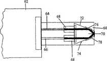
图2中给出了本发明第二个实施例中的第一种使用模式下的光连接器。本实施例中,套管60与连接器主体外壳62接触,其包含了标准部件,例如弹簧触点、闭锁机制和应变消除形式。套管包含第一和第二光信号导向装置,也即一定长度的光纤64、66-如第一个实施例-送入准直器件68,例如GRIN透镜,准直器将其引导至折射器件70,后者的两个壁72、74上各有一个折射装置76、78。这些折射装置可以采取的形式是局部空气间隙,或填充了一些低折射率介质的间隙,或者真空,或者是表面72、74外部的反射表面。Fig. 2 shows the optical connector in the first use mode in the second embodiment of the present invention. In this embodiment, the
使用这些反射装置允许光纤64、66基本平行的从端口1和端口2(未示出)退出连接器外壳62。由于之后连接器能够采用标准光纤连接器中常用的制备技术,其在制备和使用方面具有相当多的优点。图3给出了第二种使用模式下用插口(receptacle)80将两个连接部分匹配到一起,插口能精确的对准连接部分。The use of these reflective means allows the
图4a中给出了类似的装置,但其集成了两个额外的特征。第一个特征是连接部分的一个或两个前表面进行抛光,在匹配面83内产生了一个较小的曲率,例如FC/PC光纤连接器中常用的20mm半径左右。此时,当连接部分互相匹配,闭合力略微展平了连接部分的端面,从而保证匹配面的中心具有非常好的物理接触。一般来说,连接力在1kg左右,直径大约为250微米区域的玻璃被展平。A similar setup is shown in Figure 4a, but with two additional features integrated. The first feature is that one or both front surfaces of the connecting part are polished to produce a small curvature in the mating surface 83, such as a radius of about 20 mm commonly used in FC/PC fiber optic connectors. At this point, when the connecting parts are mated with each other, the closing force slightly flattens the end faces of the connecting parts, thereby ensuring very good physical contact at the center of the mating faces. Generally speaking, the connection force is around 1kg, and the glass is flattened in a region with a diameter of about 250 microns.
第二个特征是使用了快速闭合机制,例如BelvilleTM垫圈79就放在需要匹配的一个表面之前。最好将第一连接部分的套管从一端插入到定位插口(例如穿板式连接器固定架81)中,然后把垫圈从另外一端插入插口,直到垫圈接触到第一连接部分的全内反射表面的外边缘。最后第二连接部分从插口的另一端插入且向前推,直到第二连接部分的匹配面刚刚接触到BelvilleTM垫圈的外表面(见图4b)。垫圈的曲率自动地确保了两个匹配面之间有一个适当的最小距离(10-100微米)。此外第二连接部分的压力迫使垫圈变形并展平,因为垫圈仅占据了第一连接部分全内反射表面的凸起不如内部更为强烈的外缘部分(见图4c),这样两个匹配面可以很好的结合。(连接器外壳的背面有一个更方便的弹簧,可以很容易的从10微米拉伸到100微米,而不会显著减小压力)。The second feature is the use of a quick closure mechanism such as a BelvilleTM washer 79 placed just before a surface to be mated. It is best to insert the bushing of the first connection part into the positioning socket (such as the through-board connector holder 81) from one end, and then insert the gasket into the socket from the other end until the gasket touches the total internal reflection surface of the first connection part the outer edge of the . Finally the second connecting part is inserted from the other end of the socket and pushed forward until the mating face of the second connecting part just touches the outer surface of the Belville™ washer (see Figure 4b). The curvature of the gasket automatically ensures an appropriate minimum distance (10-100 microns) between the two mating surfaces. In addition, the pressure of the second connection part forces the gasket to deform and flatten, because the gasket only occupies the outer edge part of the first connection part whose total internal reflection surface is less convex than the inner part (see Figure 4c), so that the two mating surfaces Can be combined very well. (There is a more convenient spring on the back of the connector housing that can be easily stretched from 10 microns to 100 microns without significantly reducing the pressure).
在此强调一下BelvilleTM垫圈特征并不是曲面匹配面所必需使用的,而仅仅是性能增强,因为其增强了对连接部分对最后闭合的速度和控制。It is emphasized here that the BelvilleTM gasket feature is not required for use with curved mating surfaces, but is merely a performance enhancement as it enhances the speed and control of the final closure of the joint.
除了在一个或两个匹配面上提供连续曲率,还可以采用阶形表面设置(未示出),其中平面的,或者甚至曲面的匹配面替换成了垫圈可以嵌入的凹槽,凹槽的深度应该使得垫圈仍能让相对的匹配面满足其距离函数。In addition to providing continuous curvature on one or both mating faces, it is also possible to employ a stepped surface arrangement (not shown) in which the planar, or even curved, mating face is replaced by a groove into which the washer fits, the depth of the groove being It should be such that the gasket still allows the opposing mating face to satisfy its distance function.
图4d中所示的一个附加特征是在用传统连接器方法制备的连接器内集成了一对TIR(全内反射表面)界面。当该连接器与传统连接器或连接器对相匹配时,该连接器内含的机械特征将两个TIR表面互相推近。这样做的优点是提供了一个密封容积来保护TIR表面,而另一个优点在于容许传统连接器的互用性。An additional feature shown in Figure 4d is the integration of a pair of TIR (total internal reflection surface) interfaces within a connector prepared by conventional connector methods. When the connector is mated with a conventional connector or connector pair, mechanical features incorporated into the connector push the two TIR surfaces closer to each other. This has the advantage of providing a sealed volume to protect the TIR surface, and has the additional advantage of allowing interoperability with conventional connectors.
图5阐释了本发明第三个实施例中的光连接器。其给出了一个曲面折射器件82(半球透镜),其实现的折射功能与图2和3中所示的器件相同,但其额外使用了其曲面来实现准直和聚焦操作。Fig. 5 illustrates an optical connector in a third embodiment of the present invention. It presents a curved refractive device 82 (hemispherical lens) which performs the same refraction function as the device shown in Figures 2 and 3, but additionally uses its curved surface for collimation and focusing operations.
图6所示的第四个实施例中,套管86包住了一个渐变折射率(GRIN)透镜84,后者用于对光纤85的射线同时实现聚焦和射束偏转功能。优选使用高孔径GRIN,数值孔径大约是0.6,例如纤芯接触半径处的折射率是1.468(SMF28光纤),从而将背反射最小化,而中心折射率是1.85,光束入射角~35度。这样就很容易的超过了高折射率材料和空气之间32度的临界角。In a fourth embodiment shown in FIG. 6 , a
GRIN透镜长度是1/4螺距(因此能够将在光纤上的位置转换成在匹配面中心的角度)。光纤尽可能越互相靠近越有利,因为这样能减少连接器套管的角对准公差,典型的透镜长度大约为0.2mm,纤芯直径大约为125mm,总直径在0.15到0.25mm之间。为了便于处理,如果需要可以将长度增加到3/4个螺距。这是一种尤其利于装配的结构,因为部件呈圆对称-GRIN透镜是一段很短的圆柱部分,主套管的孔可以是具有七根光纤的光纤直径的三倍大小(如图16),或者将两根光纤非常靠近的放在双孔套管内,同时圆柱透镜接触到套管内凹槽的底端。GRIN透镜所需的折射率范围较大,其制备可以在拉丝之前将不同的玻璃熔融成同心管来完成。The GRIN lens length is 1/4 pitch (thus being able to convert the position on the fiber to the angle at the center of the mating plane). It is advantageous to have the fibers as close to each other as possible to reduce the angular alignment tolerance of the connector ferrule, typical lens length is about 0.2mm, core diameter is about 125mm, and the overall diameter is between 0.15 and 0.25mm. For easier handling, the length can be increased to 3/4 pitch if desired. This is a structure that is especially convenient for assembly because of the circular symmetry of the parts - the GRIN lens is a very short cylindrical section, the bore of the main ferrule can be three times the diameter of a fiber with seven fibers (Fig. 16), Alternatively, place the two fibers very close together in the dual-bore ferrule, with the cylindrical lens touching the bottom of the groove in the ferrule. The wide range of refractive indices required for GRIN lenses can be fabricated by fusing different glasses into concentric tubes prior to drawing.
图7给出了第五个实施例集成了一个球透镜87,其在玻璃-空气界面具有一个抛光平面的全内反射面88。透镜通过在曲面界面上折射来实现偏转和准直功能。光导和球透镜之间有一个空间89,其可以填充空气、真空或任何其他适当的低折射率液体。Figure 7 shows a fifth embodiment incorporating a
图8给出了第六个实施例集成了一个位于光基板92上的光波导结构90(即二氧化硅-硅波导或离子交换波导)。该结构包含了两个独立的波导94、96,分别迫使光射线从全内反射表面到达该表面上的点98或从该点出射。FIG. 8 shows a sixth embodiment integrating an optical waveguide structure 90 (ie, silica-silicon waveguide or ion-exchange waveguide) on an optical substrate 92 . The structure contains two independent waveguides 94, 96 which respectively force light rays from the total internal reflection surface to or from a point 98 on the surface.
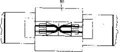
图9阐释了本发明第七个实施例中的光连接器,其给出了棱镜器件100与套管102端面相接触,后者包含了光导104、106分别与准直装置108、110结合使用,准直装置可能再次包含了GRIN透镜。棱镜器件100具有两个反射界面112、114,在连接器部分的第一种使用模式下,这两个界面能够将入射光射线从输入全部内反射到输出端。Figure 9 illustrates the optical connector in the seventh embodiment of the present invention, which shows the
图10给出了一对连接器部分采用适当的插口,例如穿板式连接器固定架118以准共线形式匹配。此处光导104内的光射线由两个棱镜器件反射两次,进入光导119,提供给与第二连接部分耦合的光学器件,随后光学器件返回的光射线进入光导116,由此通过第二棱镜器件120进入第一棱镜器件100,然后通过光导106出射。FIG. 10 shows that a pair of connector parts are mated in a quasi-collinear manner using appropriate sockets, such as bulkhead connector holders 118 . Here the light ray in the
图11给出了同一装置的可选形式,其中两个连接部分在插口117内以接近90°的角度匹配。这种装置在通讯设备中具有优势,因为其通过提供“角形反射器”功能减小了所需容纳光纤弯曲半径的空间。光信号通路如箭头所示。Figure 11 shows an alternative version of the same device, in which the two connecting parts mate within the
图12给出了同一装置的另一种可选形式,但此次利用了透镜器件的两个反射面,以此两个独立的连接器部分132、134可以和第一连接器部分130匹配。该装置的优点是,尽管其具有两个连接器的功能,第一连接部分130未连接状态(第一种使用模式)时的直通损耗也仅是单个连接器直通损耗的大小。光信号通路如箭头所示。Figure 12 shows another alternative form of the same arrangement, but this time using the two reflective surfaces of the lens device, whereby two
另一个装置设想将四个连接部分结合使用也在本发明的范围内。It is also within the scope of the invention that another arrangement envisages the use of four connecting parts in combination.
图13给出了一个光连接器装置,其中连接部分包含几对光导(光纤)呈平行排列或以任何适当的方向排列,所示的数量是三对光导,包括一个中央光纤。由于系统对称,能够沿着套管中心高精度的排列七根光纤。实例中所示,光纤1和光纤2成对,光纤3和光纤4成对,而光纤5和光纤6成对。中央光纤相当于一个标准的“直通”连接器,监控连接器的闭合时很有用。这种装置的优点在于可以通过同一个匹配孔径同时实现多个连接。很显然通过改变中央光纤的直径,可以类似的排列不同数量的光纤对,此外该特征可以结合使用任何适当的射束准直和重定向方法。Figure 13 shows an optical connector arrangement in which the connecting portion comprises several pairs of light guides (optical fibers) arranged in parallel or in any suitable orientation, the number shown being three pairs of light guides including a central optical fiber. Due to the symmetry of the system, seven optical fibers can be aligned with high precision along the center of the ferrule. In the example shown, fiber 1 is paired with
图14给出了另一个可选的多光纤装置。该装置中,两排光纤垂直对准,且光纤对连接到各自的连接部分。已给出有四个连接部分141和一个连接器校准槽142。优选在基板如硅或塑料的校准槽上安装两排光纤,随后为了获得光纤对,将这两排光纤互相垂直校准。用于反射和聚焦功能的一排光学器件可以用前述图片所示的任一种适当的光学设备来构造。Figure 14 shows another optional multi-fiber device. In this device, two rows of optical fibers are aligned vertically, and pairs of optical fibers are connected to respective connection sections. Four connecting portions 141 and one connector alignment groove 142 are shown. The two rows of fibers are preferably mounted on alignment grooves of a substrate, such as silicon or plastic, which are then aligned perpendicularly to each other in order to obtain fiber pairs. The array of optics used for the reflective and focusing functions can be constructed using any of the suitable optics shown in the preceding figures.
比较有利地,多光纤连接器装置中,连接器匹配操作会断开几对光纤,同时匹配其他对光纤。这一点有大量的网络应用。为了消除或至少减小水分侵蚀或冷凝,本发明在第一连接部分的末端使用了防潮帽,从而保持空气间隙,或者使用一次性牺牲保护层,如图1a所示。但是在一些应用场合可能认为该方法不可靠,而且其不能够在不中断全内反射的条件下清洁连接部分的末端面(匹配面)。另外,一旦保护层或末端帽脱落,就会在连接器顶端上形成冷凝,中断了全内反射,由此增加了连接器损耗,并且损害了连接器原有的保护眼睛的特性(见其后)。Advantageously, in a multi-fiber connector arrangement, the connector mating operation disconnects several pairs of fibers while mating other pairs of fibers. There are tons of web applications for this. In order to eliminate or at least reduce moisture ingress or condensation, the present invention uses a moisture cap at the end of the first connection part, thereby maintaining an air gap, or a disposable sacrificial protective layer, as shown in Figure 1a. However, this method may be considered unreliable in some applications and it is not possible to clean the end face (mating face) of the connection part without interrupting the total internal reflection. In addition, once the protective layer or end cap comes off, condensation will form on the top of the connector, interrupting total internal reflection, thereby increasing connector loss, and compromising the original eye protection characteristics of the connector (see ).
防潮的第一连接部分如图15所示。其集成了一个薄镜片151,其折射率与所示棱镜基本相同,由柔性膜152支撑,其能保持与棱镜面153几个微米的偏移,其也相当于密封。玻璃镜片和棱镜面之间形成了一个空隙154,其是密封或防潮的。当两个连接器匹配时,柔性膜发生变形,使得薄玻璃镜片接触到棱镜,从而允许光信号直通到对面的光导。因此连接器的优点是防潮,同时很容易清洁,而且在未匹配状态下不会中断全内反射。The moisture-proof first connection part is shown in FIG. 15 . It integrates a thin mirror 151 with substantially the same refractive index as the prism shown, supported by a flexible membrane 152 that maintains an offset of a few microns from the prism face 153, which also acts as a seal. A void 154 is formed between the glass mirror and the prism face, which is sealed or moisture-proof. When the two connectors mate, the flexible membrane deforms so that the thin glass mirror contacts the prism, allowing light signals to pass through to the opposite light guide. The connector therefore has the advantage of being moisture-resistant while being easy to clean without disrupting total internal reflection in the unmated state.
图16给出了防潮光连接器的一个优选实施例。左边的第一连接部分是防潮的。由于玻璃镜片163,折射率匹配玻璃(例如20微米厚)的薄膜161与全内反射面162保持了一定间隔,例如10微米,并且在该间隔内密封入可压缩的、不冷凝的低折射率介质165,例如干燥的氮气。右边的连接部分是不防潮的,有一个曲面164,例如10mm半径。这两个连接部分靠拢时,第二连接部分的圆形表面压迫表面162上的玻璃膜,从而将光信号从端口3耦合到端口4。Figure 16 shows a preferred embodiment of the moisture-proof optical connector. The first connection on the left is moisture-proof. A
为了减小匹配状态时的交叉干扰程度,玻璃镜片薄膜的匹配面相对于内部T IR表面有一个小角度。可选的或附加的,在连接之前向匹配面添加少量折射率匹配液体也可以减小匹配状态下的交叉干扰程度和损耗。To reduce the level of crosstalk in the mated state, the mating face of the glass lens film is at a small angle with respect to the inner TIR surface. Alternatively or additionally, adding a small amount of index-matching liquid to the mating surface prior to connection can also reduce cross-talk and loss in the mated state.
防潮连接器的另一种设计是选择第一连接部分端面的折射率,使得即使该端面被水气涂覆仍然能产生全内反射。为此,合适的材料是TiO2(金红石),折射率大约是2.2。需要注意的是使用折射率不同的材料时,如果需要应该使用减反射膜来减少损耗。Another design of the moisture-proof connector is to choose the refractive index of the end face of the first connecting part so that total internal reflection can still occur even if the end face is coated with moisture. A suitable material for this is TiO2 (rutile), with a refractive index of approximately 2.2. It should be noted that when using materials with different refractive indices, anti-reflection coatings should be used to reduce losses if necessary.
光信号分成两路随后又重新合并时会产生多路串扰(MPI)。大量实际应用中,需要将MPI保持较低程度——例如,干扰信号的量值需要比主信号低50dB。当本发明的连接器耦合到光学器件时,如图1所示,匹配状态下连接器内的剩余反射就构成了一个干扰信号。Multipath Interference (MPI) occurs when an optical signal splits into two paths and then recombines. In many practical applications, it is necessary to keep the MPI low—for example, the magnitude of the interfering signal needs to be 50dB lower than the main signal. When the connector of the present invention is coupled to an optical device, as shown in FIG. 1, the residual reflection within the connector in the mated state constitutes an interfering signal.
图17给出了一种方法,级联两个连接器使MPI抑制加倍。未匹配状态下,信号通路是端口1-端口2-端口1A-端口2A,实现两次全内反射。网络器件160把端口4连接到端口3A。匹配状态下,主通路是端口1-端口4-网络器件-端口3A-端口2A,而干扰信号的通路是端口1-端口2-端口1A-端口2A。这种情况下将不需要的信号进行两次反射(例如,每次-40dB,总抑制就是-80dB)。这两个连接器优选作为多路连接器结构的一部分,如图13或图14。可选择的,端口2也可以内部连接到端口1A,例如使用内部反射器。Figure 17 shows a way to double the MPI rejection by cascading two connectors. In the unmatched state, the signal path is port 1-port 2-port 1A-port 2A, realizing two total internal reflections. Network device 160 connects port 4 to port 3A. In the matching state, the main path is port 1-port 4-network device-port 3A-port 2A, and the path of the interference signal is port 1-port 2-port 1A-port 2A. In this case the unwanted signal is reflected twice (eg -40dB each for a total rejection of -80dB). These two connectors are preferably part of a multi-way connector structure, as shown in FIG. 13 or FIG. 14 . Alternatively,
图18阐释了本发明最后一个实施例中的光连接器。图18中第二种使用模式下的光连接器包含第一和第二连接部分400、402,其中分别容纳了光导404、406、408和410,不需要额外增加准直器或者折射器件。这些光导分别在匹配面上以一定角度(例如45°)会聚,其中第一连接部分400的匹配面又相当于第一种运行模式下的全内反射器。因为两个连接部分互相接触,光导404内的光射线直通到光导408,而反向射线进入光导410又直通到光导406。Fig. 18 illustrates the optical connector in the last embodiment of the present invention. The optical connector in the second usage mode in FIG. 18 includes first and second connecting
本实施例中,很重要的一点是需要精确的切割和抛光光导的匹配端,以避免出现干扰空气间隙,后者会破坏第一连接部分向第二连接部分以及反方向的通信。In this embodiment, it is important to precisely cut and polish the mating end of the light guide to avoid interfering air gaps that would disrupt communication from the first connection portion to the second connection portion and vice versa.
值得提到的是,为了实现特定功能,新的光学器件不必位于第二连接部分的外部,而可以集成在其内部。具体实例包括滤波器、抽头、传感器、隔离器和/或光电器件。It is worth mentioning that, in order to achieve a specific function, the new optical device does not have to be located outside the second connection part, but can be integrated inside it. Specific examples include filters, taps, sensors, isolators, and/or optoelectronic devices.
图19给出了本发明连接器的一个特定有利的用途。如图所示,第一连接部分(或连接器)170位于一条线路内。光分插复用装置(OADM)滤波器174连接到环路装置的第二连接部分。当两个半连接器匹配时,信号改道经过OADM滤波器发送。通信中断很短(<<10ms),而这是许多光学系统能够接受的。为了增加其他扩展性能,环路可以包括本发明中的第二光连接器176。Figure 19 shows a particularly advantageous use of the connector of the present invention. As shown, the first connection portion (or connector) 170 is located within a line. An optical add-drop multiplexer (OADM) filter 174 is connected to the second connection portion of the loop device. When the two connector halves are mated, the signal is re-routed and sent through the OADM filter. Communication interruptions are short (<<10ms), which is acceptable for many optical systems. In order to increase other expansion capabilities, the loop may include the second
连接器也能用于提供放大器节点之间的弹性点。Connectors can also be used to provide elastic points between amplifier nodes.
许多升级或维护情况下,能够测量线路上光信号而不中断通信路径是非常有用的。这可借助于耦合到抽头耦合器200(一般抽取信号的1%到10%)的连接器来实现,如图20所示。连接器再次中断光路<<10ms。随后抽头信号可按照需求送入测量装置202。In many upgrade or maintenance situations, it is useful to be able to measure the optical signal on the line without interrupting the communication path. This can be accomplished by means of a connector coupled to a tap coupler 200 (which typically taps 1% to 10% of the signal), as shown in FIG. 20 . The connector interrupts the optical path again <<10ms. The tap signal can then be sent to the
另一种引入光学抽头的装置是在连接器的两个匹配面之间创建一个大约1微米的小间隔,其能够部分衰减界面上的反射,从而将第一连接部分中的一小部分光耦合到第二连接部分的各个光导内。获得该间隔的一种方法是适当设计前述快速闭合机制,这样瞬时闭合力使得两个表面间有一个限定间距。Another means of introducing optical taps is to create a small separation of about 1 micron between the two mating faces of the connector, which partially attenuates reflections on the interface, thereby coupling a small portion of the light in the first connection part into the respective light guides of the second connection part. One way to achieve this spacing is to properly design the aforementioned snap-close mechanism so that the momentary closing force creates a defined spacing between the two surfaces.
通过连接器,放大器204可以插入到线路中。Through a connector, the amplifier 204 can be plugged into the line.
图21给出了用本发明的连接器将两个现有环路-主回路206和次级环路208-连接到单个较大的环路中。实际上为了实现该过程,优选采用下列步骤:首先在匹配两个半连接器之前,改道发送第一连接部分邻近的这些环路节点上的通信;然后匹配两个半连接器,启动放大后环路的新通路,最后将新通路对于之前改道的通信重新可用。Figure 21 shows the connection of two existing loops -
色散是许多光学系统中一个重要问题,因为其会在沿光纤系统传送信号时引起脉冲展宽。色散是高速系统(10Gbps以及更高速率)或无最佳光线类型的一个特定问题。简单的光纤系统(例如2.5Gbps,几个波长)可能配备了最小色散补偿。从几个波长升级到10Gbps/40Gbps需要增加色散补偿模块(DCMs)或色散斜率补偿模块(DSCMs)。实现该过程首先用本发明中带有抽头耦合器和色散测量装备的光连接器测量信号质量,其部分如图20所描述。然后用色散测量装备计算固定色散补偿的最优值。抽头耦合器和测量装备可以用低成本的固定DCM或DSCM替代。Chromatic dispersion is an important issue in many optical systems because it causes pulse broadening as signals are transmitted along the fiber optic system. Dispersion is a particular problem in high-speed systems (10Gbps and higher) or non-optimal light types. Simple fiber optic systems (eg 2.5Gbps, several wavelengths) may be equipped with minimal dispersion compensation. Upgrading from several wavelengths to 10Gbps/40Gbps requires the addition of dispersion compensation modules (DCMs) or dispersion slope compensation modules (DSCMs). To realize this process, first use the optical connector with tap coupler and dispersion measurement equipment in the present invention to measure the signal quality, part of which is described in FIG. 20 . The optimal value of the fixed dispersion compensation is then calculated with the dispersion measurement equipment. Tap couplers and measurement equipment can be replaced with low-cost fixed DCMs or DSCMs.
图22给出了本发明中多个连接器220a、220b用于光后连线板应用。该设置可以将电路板222插入后连线板224,光信号从各个电路板发送到光学器件或安装在电路板上的模块226。后连线板连接器可以是单个连接器或“多个”连接器。当然后连线板可以采用多种“布线”设置,此处仅给出了一种设置。本申请中使用允许信号以大角度旋转的连接器是很有利的,例如图11所示。当然也可以混合多种类型的连接器,例如图1所示的连接部分设置和图2所示的匹配连接部分设置一起位于后连线板上。这要求光导内的光射线(射束)在两种设置中有相同的角度(例如45°),射束直径和匹配面的折射率也互相匹配。后连线板的外界面(如果需要)可以直接通过板外(off-shelf)连接器228,或通过卡上(on-card)连接器(未示出)。FIG. 22 shows a plurality of
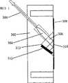
本发明的光连接器的第一连接部分采用第一种使用模式时,假设第二光导已经适当的端接,不会发射出很强的射线强度。仅需要单端口类型的光连接器时,能够在连接器内部进行第二端口(第二光导)的端接。图23a给出了前述本发明第一实施例中光连接器的第一连接部分,其中光纤300位于连接部分的主体302内,与准直器件304通信,后者依次连接到一个棱镜306,其向外的表面310作为全内反射面。如前所述也可以选择提供保护罩308。When the first connection part of the optical connector of the present invention adopts the first mode of use, assuming that the second light guide has been properly terminated, no strong radiation intensity will be emitted. When only a single-port type optical connector is required, the termination of the second port (second light guide) can be performed inside the connector. Fig. 23a has provided the first connection part of the optical connector in the first embodiment of the present invention described above, wherein the
但是不同之处在于表面310反射的光信号被反射信号投射到棱镜306的面313上的光吸收处(optical dump)312所吸收。可选择在该点放置一个反射器,后者能够将投射信号沿着基本相同的路径反射回去,反馈信号随后再次被面310反射,并沿着光纤300反射回相反的方向。这样做的效果是增强了反馈信号,其依赖于前述ALS系统。(已知系统中,主反射面(此处是310)通常与光纤轴向正交)。如果期望保持与标准FC/PC类型的光连接器相同的反射率,反射层应该是空气间隙形式。But the difference is that the optical signal reflected by the
保护眼睛装置更为普通的运行模式是将图23a所示的第一连接部分连接到其相应的第二连接部分(见图23b)。后者可以使用图1b所示的第二连接部分的形式。和图23a所示的第一连接部分一样,第二连接部分有一个光端口(光导)将光信号传送到与第二连接部分相连接的光纤。A more common mode of operation of the eye protection device is to connect the first connection part shown in Figure 23a to its corresponding second connection part (see Figure 23b). The latter can take the form of the second connection part shown in Figure 1b. Like the first connection part shown in Fig. 23a, the second connection part has an optical port (optical guide) to transmit the optical signal to the optical fiber connected to the second connection part.
另一个可选择的方面,可以将荧光材料用于镀膜312,其能在连接器内可视化的指示光信号的存在,以此满足个人要求,后者随后能够进行任何所需的操作。In another optional aspect, a fluorescent material can be used for the
后一种装置的变形提供了可视化指示光纤断裂的装置。可以用与可视LED或激光器314串连的一串三个或四个光电二极管替代前述的镀膜312来实现该功能。A variation of the latter device provides a visual indication of fiber breakage. A string of three or four photodiodes connected in series with a visible LED or laser 314 could be used instead of the
当然,除了使用第一个实施例中带角度的光导设置(图1),本领域技术人员也可以适当选择采用其他任一种设置。Of course, in addition to using the angled light guide arrangement ( FIG. 1 ) in the first embodiment, those skilled in the art may choose to adopt any other arrangement as appropriate.
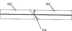
保护眼睛的连接器装置的第二个实施例是图24a和24b的主要内容,其中光纤端接到连接部分320。接收装置321处接收到的光纤末端插入直径为2.5mm的套管322,后者的外端以相对于纤芯大于50度的角度抛光掉1.5mm,如图所示。放大的切割部分如图24b中的324所示,由此投射到套管的带角度端面上的光信号被反射到套管的侧壁上,如箭头所示,其中信号被侧壁所吸收。A second embodiment of an eye protection connector arrangement is the subject of FIGS. The fiber end received at the
所示连接器的另一种使用模式中,类似的连接部分压在所示连接部分320的套管端面之上,这样破坏了套管/空气界面324的全内反射操作,由此信号能够传送到对面的套管325处,然后输出到其自身相连的光纤。In another mode of use of the illustrated connector, a similar connection portion is pressed against the sleeve end face of the illustrated
Claims (11)
Translated fromChineseApplications Claiming Priority (2)
| Application Number | Priority Date | Filing Date | Title |
|---|---|---|---|
| GB0301136AGB2387447B (en) | 2003-01-20 | 2003-01-20 | Optical connector with total internal reflection surface |
| GB0301136.8 | 2003-01-20 |
Publications (1)
| Publication Number | Publication Date |
|---|---|
| CN1739049Atrue CN1739049A (en) | 2006-02-22 |
Family
ID=9951356
Family Applications (1)
| Application Number | Title | Priority Date | Filing Date |
|---|---|---|---|
| CNA2004800024509APendingCN1739049A (en) | 2003-01-20 | 2004-01-20 | Optical connector with total internal reflection adjoining surface |
Country Status (6)
| Country | Link |
|---|---|
| US (1) | US7324728B2 (en) |
| EP (1) | EP1588200A1 (en) |
| JP (1) | JP2006515687A (en) |
| CN (1) | CN1739049A (en) |
| GB (2) | GB2387447B (en) |
| WO (1) | WO2004066006A1 (en) |
Cited By (1)
| Publication number | Priority date | Publication date | Assignee | Title |
|---|---|---|---|---|
| CN101515050B (en)* | 2008-02-19 | 2013-04-24 | 丰田合成株式会社 | Light coupler and manufacturing method thereof |
Families Citing this family (21)
| Publication number | Priority date | Publication date | Assignee | Title |
|---|---|---|---|---|
| GB2401268A (en)* | 2003-04-30 | 2004-11-03 | Polatis Ltd | Optical switching in response to the presence of a connector |
| JP4855933B2 (en)* | 2005-04-12 | 2012-01-18 | 東洋ガラス株式会社 | GRIN lens manufacturing method and GRIN lens |
| US7887243B2 (en)* | 2007-03-16 | 2011-02-15 | Honeywell Federal Manufacturing & Technologies, Llc | Miniature mechanical transfer optical coupler |
| US7682089B2 (en)* | 2007-08-15 | 2010-03-23 | Rohlen Brooks H | System and method for positioning a probe |
| US8417071B2 (en) | 2010-05-24 | 2013-04-09 | Xyratex Technology Limited | Data storage system, a modular printed circuit board, a backplane and a backplane component |
| CN101968557B (en)* | 2010-09-10 | 2013-08-28 | 华为技术有限公司 | Reflector structure |
| US8781273B2 (en) | 2010-12-07 | 2014-07-15 | Corning Cable Systems Llc | Ferrule assemblies, connector assemblies, and optical couplings having coded magnetic arrays |
| US8774577B2 (en) | 2010-12-07 | 2014-07-08 | Corning Cable Systems Llc | Optical couplings having coded magnetic arrays and devices incorporating the same |
| WO2013077880A1 (en)* | 2011-11-23 | 2013-05-30 | Intel Corporation | Optical transceiver interface with flat surface lens and flat surface interfaces |
| US8734024B2 (en)* | 2011-11-28 | 2014-05-27 | Corning Cable Systems Llc | Optical couplings having a coded magnetic array, and connector assemblies and electronic devices having the same |
| CN103454729B (en)* | 2013-09-12 | 2016-01-20 | 电子科技大学 | A kind of spaceborne space optical switch and implementation method |
| WO2015086308A1 (en) | 2013-12-09 | 2015-06-18 | Koninklijke Philips N.V. | Optical fiber connector validation |
| WO2015086272A1 (en) | 2013-12-09 | 2015-06-18 | Koninklijke Philips N.V. | Optical fiber connector |
| CN106104337B (en) | 2014-03-19 | 2019-06-21 | 3M创新有限公司 | Optical Connector |
| WO2016048825A1 (en) | 2014-09-23 | 2016-03-31 | Corning Optical Communications LLC | Optical connectors and complimentary optical receptacles having magnetic attachment |
| US10502902B2 (en) | 2015-09-30 | 2019-12-10 | Sony Corporation | Optical communication connector, optical communication cable, and electronic device |
| TWI731128B (en)* | 2016-08-10 | 2021-06-21 | 日商索尼股份有限公司 | Optical connectors, optical cables and electronic equipment |
| JP6749228B2 (en)* | 2016-12-19 | 2020-09-02 | 株式会社フジクラ | Ferrule for optical connector |
| WO2018116855A1 (en) | 2016-12-19 | 2018-06-28 | 株式会社フジクラ | Ferrule, ferrule with optical fiber, and manufacturing method of ferrule with optical fiber |
| EP3635372A4 (en)* | 2017-06-09 | 2021-05-26 | Verivin Ltd. | Characterization of liquids in sealed containers |
| WO2020102465A1 (en)* | 2018-11-14 | 2020-05-22 | Molex, Llc | Lensed optical fiber connector with feedback mirror assembly |
Family Cites Families (27)
| Publication number | Priority date | Publication date | Assignee | Title |
|---|---|---|---|---|
| US3870398A (en)* | 1973-07-05 | 1975-03-11 | Corning Glass Works | Passive coupler for optical communication system |
| US4176908A (en)* | 1977-12-14 | 1979-12-04 | Bell Telephone Laboratories, Incorporated | Devices for monitoring, switching, attenuating or distributing light |
| JPS561909A (en) | 1979-06-20 | 1981-01-10 | Hitachi Cable Ltd | Connecting method of optical fiber |
| GB2059621B (en) | 1979-09-25 | 1983-09-28 | Standard Telephones Cables Ltd | Optical fibre connector |
| JPS59109022A (en)* | 1982-12-14 | 1984-06-23 | Nippon Sheet Glass Co Ltd | Optical wave guide circuit |
| JPS6214538A (en)* | 1985-07-11 | 1987-01-23 | Mitsubishi Electric Corp | Optical data way terminal equipment |
| JPS63113509A (en)* | 1986-10-31 | 1988-05-18 | Oki Electric Ind Co Ltd | Optical jack panel |
| US6251278B1 (en)* | 1987-06-08 | 2001-06-26 | Chromatochem, Inc. | Process for separating a substance from a mixture |
| JPH04366804A (en) | 1991-06-13 | 1992-12-18 | Hitachi Ltd | two-way optical outlet |
| US5179602A (en) | 1991-07-02 | 1993-01-12 | Norcross Corporation | Magnetically operated fiber optic switch for controlling light transmission |
| US5251278A (en) | 1992-05-22 | 1993-10-05 | Samborsky James K | Fiber optic monitoring device |
| DE4233489A1 (en)* | 1992-10-05 | 1994-04-07 | Electronic Production Partners | Optical component |
| DE4242649A1 (en)* | 1992-12-17 | 1994-06-23 | Asea Brown Boveri | Optical coupler |
| US5666448A (en)* | 1995-09-22 | 1997-09-09 | Rockwell International Corporation | Variable splitting optical coupler |
| JPH09145957A (en)* | 1995-11-20 | 1997-06-06 | Fujitsu Ltd | Optical connector |
| DE19618203A1 (en) | 1996-05-07 | 1997-11-13 | Daimler Benz Ag | Light signal transmission device for assembly group carrier system |
| US6295154B1 (en) | 1998-06-05 | 2001-09-25 | Texas Instruments Incorporated | Optical switching apparatus |
| US6253007B1 (en) | 1998-07-08 | 2001-06-26 | Optical Switch Corporation | Method and apparatus for connecting optical fibers |
| JP2000231031A (en)* | 1999-02-09 | 2000-08-22 | Oyo Koden Kenkyushitsu:Kk | Optical coupler |
| JP2001075026A (en)* | 1999-09-07 | 2001-03-23 | Seikoh Giken Co Ltd | Reflection mirror type optical fiber switch |
| US6438283B1 (en) | 1999-10-08 | 2002-08-20 | Optical Switch Corporation | Frustrated total internal reflection switch using double pass reflection and method of operation |
| US6463189B1 (en) | 2000-02-24 | 2002-10-08 | Avanex Corporation | Method and apparatus for optical switching devices utilizing a bi-morphic piezoelectric apparatus |
| JP2001350105A (en)* | 2000-06-08 | 2001-12-21 | Oyokoden Lab Co Ltd | Optical switch |
| US6519382B1 (en)* | 2000-09-11 | 2003-02-11 | Optical Switch Corporation | Frustrated total internal reflection switch using waveguides and method of operation |
| US6393174B1 (en)* | 2000-11-15 | 2002-05-21 | Optical Switch Corporation | Integrated fiber array optical switch using double-pass propagation and method of operation |
| US6842564B2 (en) | 2001-04-05 | 2005-01-11 | Richard H. Laughlin | Remotely configurable add/drop for wavelength division multiplexing and method of operating the same |
| US7177494B1 (en)* | 2005-01-14 | 2007-02-13 | St. Clair Intellectual Property Consultants, Inc. | Optical control device and method |
- 2003
- 2003-01-20GBGB0301136Apatent/GB2387447B/ennot_activeExpired - Lifetime
- 2003-05-29GBGB0312244Apatent/GB2397392A/ennot_activeWithdrawn
- 2004
- 2004-01-20WOPCT/GB2004/000174patent/WO2004066006A1/ennot_activeApplication Discontinuation
- 2004-01-20CNCNA2004800024509Apatent/CN1739049A/enactivePending
- 2004-01-20JPJP2006500221Apatent/JP2006515687A/enactivePending
- 2004-01-20EPEP04703426Apatent/EP1588200A1/ennot_activeWithdrawn
- 2004-01-20USUS10/542,680patent/US7324728B2/ennot_activeExpired - Lifetime
Cited By (1)
| Publication number | Priority date | Publication date | Assignee | Title |
|---|---|---|---|---|
| CN101515050B (en)* | 2008-02-19 | 2013-04-24 | 丰田合成株式会社 | Light coupler and manufacturing method thereof |
Also Published As
| Publication number | Publication date |
|---|---|
| EP1588200A1 (en) | 2005-10-26 |
| US20060072878A1 (en) | 2006-04-06 |
| GB0312244D0 (en) | 2003-07-02 |
| GB2397392A (en) | 2004-07-21 |
| WO2004066006A1 (en) | 2004-08-05 |
| GB2387447B (en) | 2004-04-28 |
| GB2387447A (en) | 2003-10-15 |
| JP2006515687A (en) | 2006-06-01 |
| GB0301136D0 (en) | 2003-02-19 |
| US7324728B2 (en) | 2008-01-29 |
Similar Documents
| Publication | Publication Date | Title |
|---|---|---|
| CN1739049A (en) | Optical connector with total internal reflection adjoining surface | |
| US20230168435A1 (en) | Ferrule-less fiber optic connector having multiple optical fibers | |
| US5841562A (en) | Bidirectional modular optoelectronic transceiver assembly | |
| US7539367B2 (en) | Optical system connection structure, optical component, and optical communication module | |
| US9322987B2 (en) | Multicore fiber coupler between multicore fibers and optical waveguides | |
| US10718914B2 (en) | Optoelectronic module assembly having an optical fiber alignment assembly coupled to an optoelectronic device assembly | |
| EP3807686B1 (en) | Optical connectors and detachable optical connector assemblies for optical chips | |
| EP2666042B1 (en) | Electro-optical device having an elastomeric body and related methods | |
| JP2020060796A (en) | Optical connector, optical connector system, and active optical cable including the same | |
| US20120251045A1 (en) | Multi-core fiber optical coupling elements | |
| US20140185991A1 (en) | Translating lens holder assemblies employing bore relief zones, and optical connectors incorporating the same | |
| WO2017118271A1 (en) | Parallel transmission and reception optical module for dual-link transmission, and preparation method | |
| US9022669B2 (en) | Gradient index lens assemblies, fiber optic connectors, and fiber optic cable assemblies employing lens alignment channels | |
| CN108572419B (en) | Long-distance active optical cable | |
| US11609395B2 (en) | Waveguide substrates and assemblies including the same | |
| CN114966962A (en) | Back side fiber attachment to silicon photonics chip | |
| US8538229B1 (en) | Pluggable variable optical attenuators and methods for making the same | |
| US20250012973A1 (en) | Interface structure, optical connector, transmitter, receiver, optical cable, and optical communication system | |
| US8672558B2 (en) | APC adapter | |
| US12204149B2 (en) | Interposer with feedback | |
| WO2019152620A1 (en) | Fiber optical interface with reduced reflections | |
| US20250110292A1 (en) | Optical module | |
| CN217606137U (en) | Optical module | |
| US20250116824A1 (en) | Expanded beam optical ferrules | |
| CA2414795A1 (en) | Fiber optic coupler |
Legal Events
| Date | Code | Title | Description |
|---|---|---|---|
| C06 | Publication | ||
| PB01 | Publication | ||
| C10 | Entry into substantive examination | ||
| SE01 | Entry into force of request for substantive examination | ||
| C02 | Deemed withdrawal of patent application after publication (patent law 2001) | ||
| WD01 | Invention patent application deemed withdrawn after publication |