CN1738563A - inflatable device - Google Patents
inflatable deviceDownload PDFInfo
- Publication number
- CN1738563A CN1738563ACN 200380108885CN200380108885ACN1738563ACN 1738563 ACN1738563 ACN 1738563ACN 200380108885CN200380108885CN 200380108885CN 200380108885 ACN200380108885 ACN 200380108885ACN 1738563 ACN1738563 ACN 1738563A
- Authority
- CN
- China
- Prior art keywords
- bladder
- inflatable
- valve
- fluid
- support
- Prior art date
- Legal status (The legal status is an assumption and is not a legal conclusion. Google has not performed a legal analysis and makes no representation as to the accuracy of the status listed.)
- Granted
Links
- 239000012530fluidSubstances0.000claimsabstractdescription170
- 238000007789sealingMethods0.000claimsabstractdescription69
- 239000000463materialSubstances0.000claimsdescription34
- 238000000034methodMethods0.000claimsdescription25
- 230000005540biological transmissionEffects0.000claimsdescription10
- 230000008878couplingEffects0.000claimsdescription9
- 238000010168coupling processMethods0.000claimsdescription9
- 238000005859coupling reactionMethods0.000claimsdescription9
- 230000007246mechanismEffects0.000claimsdescription8
- 229920000742CottonPolymers0.000claimsdescription5
- 230000036541healthEffects0.000claimsdescription5
- 238000010276constructionMethods0.000claimsdescription3
- 239000002390adhesive tapeSubstances0.000claimsdescription2
- 239000004033plasticSubstances0.000claimsdescription2
- 229920003023plasticPolymers0.000claimsdescription2
- 238000000926separation methodMethods0.000claims16
- 238000013022ventingMethods0.000claims4
- 230000004888barrier functionEffects0.000claims3
- 238000005086pumpingMethods0.000claims2
- 239000002689soilSubstances0.000claims2
- 239000012814acoustic materialSubstances0.000claims1
- 238000012856packingMethods0.000claims1
- 230000000630rising effectEffects0.000claims1
- 239000012528membraneSubstances0.000abstractdescription44
- 230000009977dual effectEffects0.000abstractdescription2
- 239000010410layerSubstances0.000description33
- 238000012559user support systemMethods0.000description22
- 230000008901benefitEffects0.000description10
- 230000006870functionEffects0.000description8
- 239000006260foamSubstances0.000description6
- 239000007789gasSubstances0.000description5
- 239000002344surface layerSubstances0.000description5
- 230000000881depressing effectEffects0.000description4
- 230000004044responseEffects0.000description4
- 230000000153supplemental effectEffects0.000description4
- 230000008859changeEffects0.000description3
- 230000003203everyday effectEffects0.000description3
- 238000005192partitionMethods0.000description3
- 238000007493shaping processMethods0.000description3
- 229920002994synthetic fiberPolymers0.000description3
- 230000009471actionEffects0.000description2
- 230000004075alterationEffects0.000description2
- 230000000712assemblyEffects0.000description2
- 238000000429assemblyMethods0.000description2
- 230000000994depressogenic effectEffects0.000description2
- 239000000835fiberSubstances0.000description2
- 230000006872improvementEffects0.000description2
- 230000004048modificationEffects0.000description2
- 238000012986modificationMethods0.000description2
- 239000012209synthetic fiberSubstances0.000description2
- XLYOFNOQVPJJNP-UHFFFAOYSA-NwaterSubstancesOXLYOFNOQVPJJNP-UHFFFAOYSA-N0.000description2
- 230000003213activating effectEffects0.000description1
- 230000004913activationEffects0.000description1
- 239000000853adhesiveSubstances0.000description1
- 230000001070adhesive effectEffects0.000description1
- 239000003570airSubstances0.000description1
- 238000005452bendingMethods0.000description1
- 230000009286beneficial effectEffects0.000description1
- 239000002775capsuleSubstances0.000description1
- 238000001816coolingMethods0.000description1
- 230000005611electricityEffects0.000description1
- 239000004744fabricSubstances0.000description1
- 239000003292glueSubstances0.000description1
- 230000001788irregularEffects0.000description1
- 239000007788liquidSubstances0.000description1
- 238000005259measurementMethods0.000description1
- 239000002184metalSubstances0.000description1
- 239000002991molded plasticSubstances0.000description1
- 230000007935neutral effectEffects0.000description1
- 238000003825pressingMethods0.000description1
- 230000008569processEffects0.000description1
- 230000004083survival effectEffects0.000description1
- 230000009182swimmingEffects0.000description1
- 239000004758synthetic textileSubstances0.000description1
- PICXIOQBANWBIZ-UHFFFAOYSA-Nzinc;1-oxidopyridine-2-thioneChemical class[Zn+2].[O-]N1C=CC=CC1=S.[O-]N1C=CC=CC1=SPICXIOQBANWBIZ-UHFFFAOYSA-N0.000description1
Images


Landscapes
- Mattresses And Other Support Structures For Chairs And Beds (AREA)
Abstract
Description
Translated fromChinese本发明的技术领域Technical Field of the Invention
这项发明涉及充气装置,具体地说,涉及可充气的支撑装置。This invention relates to inflatable devices and, in particular, to inflatable support devices.
本发明的现有技术Prior Art of the Invention
充气装置被用于各种各样的需要浮力或褥垫支撑、空间有限或希望便于携带的环境。例如,可充气的底垫,垫子和其他的身体支撑物被用于诸如野营、医院被褥和在家中每天或偶尔使用的被褥之类的应用。这样的充气装置有附加的优势,即支撑的充气程度能为了提供对不规则物体(例如,人体)的均匀支撑进行调整。其它充气装置的例子包括小船、筏子和其它在水中使用的装置,在这种情况下使用充气装置可能有益于支撑、健康、舒适和安全。Inflatables are used in a variety of situations where buoyancy or mattress support is required, space is limited, or portability is desired. For example, inflatable underpads, cushions and other body supports are used in applications such as camping, hospital bedding, and everyday or occasional bedding at home. Such an inflatable device has the added advantage that the degree of inflation of the support can be adjusted in order to provide uniform support for irregular objects such as a human body. Examples of other inflatable devices include boats, rafts, and other devices used in water, where the use of an inflatable device may be beneficial for support, health, comfort and safety.
充气装置通常包括用于装置的充气和放气的阀门。充气装置所的阀门可能包括自紧密封阀门,例如,在通过引证在此将其全部并入的美国专利第6,237,621号中描述的那些。充气装置还可能包括诸如手动或电动泵之类的机构,帮助装置充气和/或放气。Inflatable devices typically include valves for inflation and deflation of the device. Valves in the inflatable device may include self-tight sealing valves such as those described in US Patent No. 6,237,621, which is hereby incorporated by reference in its entirety. Inflatable devices may also include a mechanism, such as a manual or electric pump, to help inflate and/or deflate the device.
本发明的概述Summary of the invention
本发明的第一方面指向一种充气装置,其中包括:(A)可充气囊状物;和(B)流动控制器,后者包括:(i)与可充气囊状物耦合并且受其支撑的阀门,阀门是为控制流体进出囊状物的流动而配置和安排的,阀门形成密封以便响应囊状物里面的流体压力将流体维持在囊状物中;和(ii)为在机械装置起作用的时候打开阀门而配置和安排的机械装置。A first aspect of the invention is directed to an inflatable device comprising: (A) an inflatable bladder; and (B) a flow controller comprising: (i) coupled to and supported by the inflatable bladder a valve configured and arranged to control the flow of fluid into and out of the bladder, the valve forming a seal to maintain the fluid within the bladder in response to fluid pressure within the bladder; and A mechanical device configured and arranged to open a valve when activated.
所述充气装置可能进一步包括与囊状物耦合为装入阀门而配置和安排的隔舱,所述隔舱适合接受来自泵的增压流体。在一些实施方案中,阀门是包括适合在所述隔舱中存在空气压力时防止阀门打开的盖子的自紧密封阀门,其中盖子和机械装置是这样配置的,以致当机械装置起作用的时候它偏置打开盖子。自紧密封阀门可能进一步包括为响应囊状物里面的流体压力形成密封而配置和安排的隔膜,其中隔膜和机械装置是这样配置的,以致当机械装置起作用的时候,它偏置打开盖子和隔膜。非必选的是,机械装置被装入隔舱。机械装置可能与囊状物耦合并且受囊状物支撑。在一些实施方案中,机械装置包括电机械装置。The inflatable device may further include a compartment coupled with the bladder configured and arranged to receive the valve, the compartment being adapted to receive pressurized fluid from the pump. In some embodiments, the valve is a self-tightening sealing valve comprising a cover adapted to prevent opening of the valve in the presence of air pressure in said compartment, wherein the cover and mechanism are arranged so that it Bias to open the lid. The self-tight sealing valve may further include a diaphragm configured and arranged to form a seal in response to fluid pressure inside the bladder, wherein the diaphragm and mechanism are configured so that when the mechanism is activated, it biases open the lid and diaphragm. Optionally, the mechanism is housed in the compartment. A mechanical device may be coupled to and supported by the bladder. In some embodiments, the mechanical device includes an electromechanical device.
在一些实施方案中,电机械装置适合与适合将增压流体提供给所述隔舱的泵协同打开阀门给囊状物充气。非必选的是,电机械装置适合打开阀门,将囊状物中的流体放掉。在一些实施方案中,泵是通过软管与隔舱耦合的。泵可能被包在隔音材料之内。在一些实施方案中,隔舱是沿着可充气囊状物的轮廓或在可充气囊状物的轮廓之内安排的。In some embodiments, the electromechanical device is adapted to open a valve to inflate the bladder in cooperation with a pump adapted to provide pressurized fluid to said compartment. Optionally, the electromechanical means are adapted to open the valve to release fluid from the bladder. In some embodiments, the pump is coupled to the compartment by a hose. The pump may be enclosed in soundproofing material. In some embodiments, the compartments are arranged along or within the contour of the inflatable bladder.
充气装置可能是底垫。底垫可能包括补充材料,而且流动控制器的一部分至少部分地被补充材料支撑着。在一些实施方案中,泵的一部分至少部分地被补充材料支撑着。泵可能被可充气囊状物支撑着。The inflatable device may be the bottom cushion. The base pad may include supplemental material, and a portion of the flow controller is at least partially supported by the supplemental material. In some embodiments, a portion of the pump is at least partially supported by the supplemental material. The pump may be supported by an inflatable bladder.
本发明的另一方面指向可充气的底垫,其中包括:(A)第一个可充气囊状物;(B)与第一个可充气囊状物毗邻安排的第二个可充气囊状物;(C)流动控制器,其中包括:(i)与第一囊状物耦合并且受其支撑的第一阀门,第一阀门是为控制流体进出第一囊状物的流动而配置和安排的,其中第一阀门形成密封以便响应第一囊状物中的流体压力将流体维持在第一囊状物中;(ii)与第二囊状物耦合并且受其支撑的第二阀门,第二阀门是为控制流体进出第一囊状物的流动而被配置和安排的,第二阀门形成密封以便响应第二囊状物里面的流体压力将流体维持在第二囊状物中;以及(ii)为在电机械装置处于第一个起作用位置的时候打开第一阀门和在电机械装置处于第二个起作用位置的时候打开第二阀门而配置和安排的电机械装置;以及(D)与囊状物耦合为装入第一阀门和第二阀门而配置和安排的隔舱,所述隔舱适合接受来自泵的增压流体。Another aspect of the invention is directed to an inflatable bottom cushion comprising: (A) a first inflatable bladder; (B) a second inflatable bladder disposed adjacent to the first inflatable bladder; (C) a flow controller comprising: (i) a first valve coupled to and supported by the first bladder, the first valve being configured and arranged to control the flow of fluid into and out of the first bladder wherein the first valve forms a seal to maintain fluid within the first bladder in response to fluid pressure in the first bladder; (ii) a second valve coupled to and supported by the second bladder, The second valve is configured and arranged to control the flow of fluid into and out of the first bladder, the second valve forming a seal to maintain fluid in the second bladder in response to fluid pressure within the second bladder; and ( ii) an electromechanical device configured and arranged to open a first valve when the electromechanical device is in a first operative position and a second valve when the electromechanical device is in a second operative position; and (D ) coupled with the bladder to a compartment configured and arranged to receive the first valve and the second valve, the compartment adapted to receive pressurized fluid from the pump.
在一些实施方案中,隔舱与底垫轮廓齐平或在底垫轮廓之内。在一些实施方案中,隔舱是V形的。非必选的是,电机械装置是这样配置的,以致在第一个起作用位置并且有增压流体提供给所述隔舱之时,第一囊状物被流体填充,而当所述电机械装置处于第二个起作用位置并且增压流体提供给所述隔舱的时候,第二囊状物被流体填充。在一些实施方案中,隔舱与第一囊状物和第二囊状物的组合轮廓齐平或在所述组合轮廓之内。电机械装置可能包括至少打开第一阀门的传动臂。电机械装置可能包括打开第一阀门和第二阀门的传动臂。在一些实施方案中,所述传动臂是弧形的(arcurate)。In some embodiments, the compartments are flush with or within the contours of the bottom mat. In some embodiments, the compartments are V-shaped. Optionally, the electromechanical device is configured such that in the first active position and when pressurized fluid is supplied to the compartment, the first bladder is filled with fluid, and when the electromechanical device The second bladder is filled with fluid when the mechanism is in the second active position and pressurized fluid is supplied to the compartment. In some embodiments, the compartment is flush with or within the combined contour of the first bladder and the second bladder. The electromechanical device may include an actuator arm that opens at least the first valve. The electromechanical device may include an actuator arm that opens the first valve and the second valve. In some embodiments, the transmission arm is arcurate.
本发明的另一方面指向可充气的底垫,其中包括:可充气囊状物;铰接装置,包括:把可充气囊状物支撑在地板上的支撑结构,所述支撑结构有沿着支撑结构的长度安排的众多区域,和至少一个接缝,所述的至少一个接缝每个都位于中间毗邻一些所述区域。Another aspect of the present invention is directed to an inflatable undercushion comprising: an inflatable bladder; an articulation comprising: a support structure for supporting the inflatable bladder on the floor, said support structure having a a plurality of regions arranged in length, and at least one seam each intermediately adjacent some of said regions.
在一些实施方案中,铰接装置包括相对另一个区域移动至少一个区域的马达。在一些实施方案中,所述区域由腿部区域、躯干区域和头部区域组成。充气装置可能是底垫。充气装置可能是充气床垫。充气装置可能适合在铰接装置起作用之时放气。充气装置可能适合在铰接装置后来起作用之时再次充气。在一些实施方案中,至少所述区域之一实质上是连续的。在其它的实施方案中,每个所述区域实质上都是连续的。In some embodiments, the articulation includes a motor that moves at least one region relative to another region. In some embodiments, the region consists of a leg region, a torso region, and a head region. The inflatable device may be the bottom cushion. The inflatable device may be an air mattress. Inflatables may be suitable for deflation while the articulation is in action. The inflator may be adapted to re-inflate when the articulation is subsequently activated. In some embodiments, at least one of the regions is substantially continuous. In other embodiments, each of said regions is substantially continuous.
本发明的另一方面指向充气装置,其中包括:第一个可充气囊状物;和与第一囊状物毗邻安排的第二个可充气囊状物,所述的第一囊状物和第二囊状物适合在对应的第一充气水平下将身体维持在第一个身体位置,而在对应的第二充气水平下将身体维持在第二个身体位置。Another aspect of the present invention is directed to an inflatable device comprising: a first inflatable bladder; and a second inflatable bladder disposed adjacent to the first bladder, said first bladder and The second bladder is adapted to maintain the body in the first body position at the corresponding first inflation level and maintain the body in the second body position at the corresponding second inflation level.
充气装置可能进一步包括至少安排在第一囊状物和第二囊状物之一上的舒适层。在一些实施方案中,第一个身体位置是平卧,而第二个身体位置是斜倚着。在一些实施方案中,第一囊状物的第一充气水平高于第一囊状物的第二充气水平,而且第二囊状物的第一充气水平高于第二囊状物的第二充气水平。第一囊状物可能适合支撑使用者的躯干,而第二囊状物是枕头。The inflatable device may further comprise a comfort layer arranged on at least one of the first bladder and the second bladder. In some embodiments, the first body position is supine and the second body position is reclining. In some embodiments, the first inflation level of the first bladder is higher than the second inflation level of the first bladder, and the first inflation level of the second bladder is higher than the second inflation level of the second bladder. inflation level. The first bladder may be adapted to support the user's torso, while the second bladder is a pillow.
本发明的又一方面指向可充气的身体支撑装置,其中包括:可充气囊状物;和与可充气囊状物可拆开地连接并且适合支撑可充气囊状物的支架,所述支架包括安排在可充气囊状物下面的隔舱。可充气的身体支撑装置可能进一步包括与所述支架可拆开地连接并且将可充气囊状物支撑在隔舱上面的框架。Yet another aspect of the present invention is directed to an inflatable body support device comprising: an inflatable bladder; and a frame detachably connected to the inflatable bladder and adapted to support the inflatable bladder, the frame comprising Compartment arranged under the inflatable bladder. The inflatable body support device may further include a frame detachably connected to the frame and supporting the inflatable bladder above the compartment.
可充气囊状物可以与支架铰接地耦合。在一些实施方案中,可充气囊状物通过与支架铰接的框架与铰接地支架耦合。在一些实施方案中,可充气囊状物是充气床垫。在其它的实施方案中,可充气囊状物是椅子。框架可能适合相对支架滑移、旋转或举起可充气囊状物。在一些实施方案中,可充气的身体支撑装置进一步包括准许相对支架滑移、旋转和举起可充气囊状物的铁轨、导轨或轨道。在一些实施方案中,可充气的身体支撑装置进一步包括将可充气囊状物维持在升高的位置的锁定机构。The inflatable bladder can be hingedly coupled to the bracket. In some embodiments, the inflatable bladder is coupled to the hinged support via a frame that is hinged to the support. In some embodiments, the inflatable bladder is an air mattress. In other embodiments, the inflatable bladder is a chair. The frame may be adapted to slide, rotate or lift the inflatable bladder relative to the frame. In some embodiments, the inflatable body support device further includes rails, rails or tracks that permit sliding, rotation and lifting of the inflatable bladder relative to the frame. In some embodiments, the inflatable body support device further includes a locking mechanism to maintain the inflatable bladder in the raised position.
本发明的又一方面指向使用包括可充气囊状物和至少一个定形构件的可成形充气装置的方法,其中所述的至少一个定形构件与所述可充气囊状物是这样组合的以致可充气囊状物在充气条件下与所述定形构件组合的总体形状实质上不同于可充气囊状物独自的充气形状,所述方法包括如下行为:调整那至少一个定形构件使之对应于选定的第一形状;给可充气囊状物充气使之达到选定的第一形状;调整那至少一个定形构件使之对应于选定的第二形状;和给囊状物充气或放气使之达到选定的第二形状。Yet another aspect of the present invention is directed to a method of using a shapeable inflatable device comprising an inflatable bladder and at least one shape-setting member, wherein said at least one shape-setting member is combined with said inflatable bladder such that inflatable The overall shape of the bladder in combination with the shaping member in an inflated condition is substantially different from the inflated shape of the inflatable bladder alone, the method comprising the act of adjusting the at least one shaping member to correspond to the selected first shape; inflating the inflatable bladder to achieve the selected first shape; adjusting the at least one shape-setting member to correspond to the selected second shape; and inflating or deflating the bladder to achieve The selected second shape.
所述方法可能进一步包括在选定的第一形状之时用身体的第一部分使用充气装置和在选定的第二形状之时用身体的第二部分使用充气装置的行为。在一些实施方案中,第一个调整行为形成适合头部使用的装置,而第二个调整行为形成适合背部和腿部之一使用的装置。在一些实施方案中,将囊状物充气到选定的第一形状的行为形成第一尺寸的垫枕,而将囊状物充气到选定的第二形状的行为形成第二尺寸的垫枕。在一些实施方案中,至少第一形状和第二形状之一是非圆筒形的。在一些实施方案中,至少一个紧固件直接与可充气囊状物连接。在一些实施方案中,调整使那至少一个定形构件使之对应于选定的第二形状的行为包括调整刚性构件。The method may further comprise the act of using the inflatable device with the first part of the body when the first shape is selected and using the inflatable device with the second part of the body when the second shape is selected. In some embodiments, a first act of adjustment results in a device adapted for head use and a second act of adjustment results in a device adapted for use on one of the back and legs. In some embodiments, the act of inflating the bladder to a selected first shape forms a bolster of a first size, and the act of inflating the bladder to a selected second shape forms a bolster of a second size . In some embodiments, at least one of the first shape and the second shape is non-cylindrical. In some embodiments, at least one fastener is directly attached to the inflatable bladder. In some embodiments, the act of adjusting the at least one shape-setting member to correspond to the selected second shape includes adjusting the rigidizing member.
本发明的另一方面指向使用包括囊状物的可成形充气装置的方法,所述方法包括如下行为:调整囊状物使之对应于选定的第一形状;给可充气囊状物充气使之达到选定的第一形状;调整囊状物使之对应于选定的第二形状;和给所述的囊状物充气或放气使之达到选定的第二形状。在一些实施方案中,调整囊状物使之符合选定的第一形状的行为和调整囊状物使之符合选定的第二形状的行为之一包括折叠囊状物。Another aspect of the invention is directed to a method of using a formable inflatable device comprising a bladder, the method comprising the acts of: adjusting the bladder to correspond to a selected first shape; inflating the inflatable bladder to to achieve the selected first shape; adjust the bladder to correspond to the selected second shape; and inflate or deflate said bladder to achieve the selected second shape. In some embodiments, one of the act of conforming the bladder to the selected first shape and the act of conforming the bladder to the selected second shape comprises folding the bladder.
本发明的又一方面指向可充气的充气床垫,其中包括:可充气囊状物;和毗邻可充气囊状物的加热器。在一些实施方案中,加热器由至少一个有安排在囊状物上的粘胶带的电阻片组成。在一些实施方案中,囊状物有长度,而且那至少一个电阻片实质上沿着囊状物的整个长度延伸。加热器可能是沿着底垫的尺寸均匀地布置的。在一些实施方案中,加热器是仅仅沿着底垫的一部分布置的。Yet another aspect of the invention is directed to an inflatable air mattress comprising: an inflatable bladder; and a heater adjacent to the inflatable bladder. In some embodiments, the heater consists of at least one resistive sheet with an adhesive tape disposed on the bladder. In some embodiments, the bladder has a length, and the at least one resistive sheet extends along substantially the entire length of the bladder. The heaters may be evenly spaced along the dimensions of the underpad. In some embodiments, the heater is disposed along only a portion of the bottom mat.
本发明的又一方面指向使用包括可充气囊状物、表面层和安排在囊状物和表面层之间的第一中间层的充气装置的方法,所述方法包括如下行为:除去第一中间层;以及把第二中间层放在安排在囊状物和表面层之间的位置。在一些实施方案中,第一中间层至少由下列材料之一组成:泡沫塑料、棉花和绒毛。在一些实施方案中,第一中间层和第二中间层包括彼此相同的材料。在一些实施方案,第一中间层和第二中间层包括彼此不同的材料。Yet another aspect of the invention is directed to a method of using an inflatable device comprising an inflatable bladder, a surface layer and a first intermediate layer arranged between the bladder and the surface layer, the method comprising the act of removing the first intermediate layer layer; and placing a second intermediate layer in a position arranged between the bladder and the surface layer. In some embodiments, the first intermediate layer is composed of at least one of the following materials: foam, cotton, and fleece. In some embodiments, the first intermediate layer and the second intermediate layer comprise the same material as each other. In some embodiments, the first intermediate layer and the second intermediate layer comprise different materials from each other.
附图简要说明Brief description of the drawings
这些附图不倾向于按比例绘制。在这些附图中,在各种不同的附图中举例说明的每个同一的或几乎同一的零部件是用相似的数字表现的。为了清楚,并非每个零部件在每张附图中都被标注出来。在这些附图中:The drawings are not intended to be drawn to scale. In the drawings, each identical or nearly identical component that is illustrated in various figures is represented by a like numeral. For purposes of clarity, not every component may be labeled in every drawing. In these drawings:
图1是包括本发明的阀门和电机械装置的流体移动装置的一个实施方案的剖视图;Figure 1 is a cross-sectional view of one embodiment of a fluid moving device comprising a valve and an electromechanical device of the present invention;
图2是包括本发明的两个阀门和众多激励装置的流体的移动装置的另一个实施方案的剖视图;Figure 2 is a cross-sectional view of another embodiment of a fluid moving device comprising two valves and a plurality of activating devices of the present invention;
图3A是本发明的另一个实施方案的剖视图,其中包括在第一种条件下的流体移动装置、两个阀门和传动装置;Figure 3A is a cross-sectional view of another embodiment of the invention including the fluid moving device, two valves and the transmission in a first condition;
图3B举例说明在第二种条件下本发明的图3A所示实施方案;Figure 3B illustrates the embodiment of the invention shown in Figure 3A under a second condition;
图4A-4C举例说明与本发明的自紧密封阀门组合的传动装置组件的另一个实施方案;Figures 4A-4C illustrate another embodiment of an actuator assembly combined with the self-tightening sealing valve of the present invention;
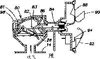
图5A-5C举例说明充气装置的可仿效实施方案,其中流动控制器的一部分与可充气囊状物耦合,而且至少流动控制器的一部分用分可充气囊状物支撑着;5A-5C illustrate an exemplary embodiment of an inflatable device wherein a portion of the flow controller is coupled to an inflatable bladder and at least a portion of the flow controller is supported by the inflatable bladder;
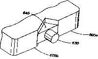
图6A-6C是双重囊状物底垫的可仿效实施方案的例证,其中第一个可充气囊状物和第二个可充气囊状物都与公用的流体控制器流体耦合;6A-6C are illustrations of an exemplary embodiment of a dual bladder base pad, wherein both a first inflatable bladder and a second inflatable bladder are fluidly coupled to a common fluid controller;
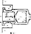
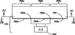
图7A-7C是底垫和相关结构的可仿效实施方案的例证;Figures 7A-7C are illustrations of exemplary embodiments of base pads and related structures;
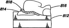
图8A-8D是包括多位置身体支撑装置的充气装置的可仿效实施方案的例证;8A-8D are illustrations of exemplary embodiments of inflatable devices including multi-position body support devices;
图9A-9B是包括储藏隔舱的充气装置的实施方案的示意例证;9A-9B are schematic illustrations of embodiments of an inflatable device including a storage compartment;
图10A-10C举例说明包括与隔膜组合的可充气囊状物的充气装置实施方案;10A-10C illustrate an embodiment of an inflatable device comprising an inflatable bladder in combination with a membrane;
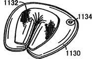
图11A-11D举例说明包括与外层膜片组合的可充气囊状物可成形充气装置的可仿效实施方案;Figures 11A-11D illustrate an exemplary embodiment of a formable inflation device comprising an inflatable bladder in combination with an outer membrane;
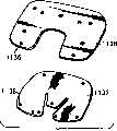
图12A-12B举例说明可仿效的实施方案包括被附上到外层膜片使用紧固件的可充气囊状物;Figures 12A-12B illustrate an exemplary embodiment comprising an inflatable bladder attached to the outer membrane using fasteners;
图13a-13H举例说明可充气囊状物附着到外层膜片上的进一步可仿效的实施方案;Figures 13a-13H illustrate a further exemplary embodiment of an inflatable bladder attached to the outer membrane;
图14-15举例说明包括有可以被包在或部分地包在覆盖层之内的用于充气和放气的阀门的可充气囊状物的可成形充气装置附加实施方案;14-15 illustrate an additional embodiment of a formable inflatable device including an inflatable bladder having a valve for inflation and deflation that may be enclosed or partially enclosed within a cover layer;
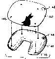
图16-18举例说明作为可以在第一充气水平充当颈部或腿部支撑而在第二充气水平充当腰部支撑的枕头成形的可成形充气装置;16-18 illustrate a shapeable inflatable device shaped as a pillow that can act as neck or leg support at a first inflation level and lumbar support at a second inflation level;
图19-20举例说明能在不同的充气水平实现不同的功能的充气装置的另一个实施方案。19-20 illustrate another embodiment of an inflatable device capable of performing different functions at different inflation levels.
本发明的详细描述Detailed description of the invention
这项发明在它的应用方面不局限于在下面的描述中陈述的或在那些附图中图解说明的零部件的构造和安排的细节。本发明能够用其它实施方案体现和以各种不同的方式实践或实施。另外,在此使用的措辞和术语是为了描述而不应该作为限制对待。“包括”、“其中包括”、或“有”、“包含”或“包括”以及它们的变化的使用在本文中意味着囊括其后列出的项目和其同等物以及附加的项目。The invention is not limited in its application to the details of construction and arrangement of parts set forth in the following description or illustrated in those drawings. The invention is capable of other embodiments and of being practiced or carried out in various ways. Also, the phraseology and terminology used herein are for the purpose of description and should not be regarded as limiting. The use of "including," "including," or "having," "comprising" or "comprising" and variations thereof herein is meant to encompass the items listed thereafter and equivalents thereof as well as additional items.
如同在此使用的那样,“可充气的”将被理解为是能够用诸如气体、空气、液体之类的任何流体充气的。如同在此使用的那样,“充气装置”包括至少一个能充气和密封的而且可能包括许多种形状、尺寸、构造和材料的流体不能渗透的囊状物。As used herein, "inflatable" will be understood to be capable of being inflated with any fluid, such as gas, air, liquid or the like. As used herein, an "inflator" includes at least one fluid-impermeable bladder that is inflatable and sealable and may include a wide variety of shapes, sizes, configurations and materials.
本发明的一个方面涉及能连同电机械装置一起使用偏置打开阀门的自紧密封阀门。具体地说,在一个实施方案中,本发明涉及能在流体移动装置的压力下打开给充气装置充气而且不需要来自电机械装置的任何帮助就能在来自充气装置内的流体的压力下关闭的自紧密封阀门。在这个实施方案中,电机械装置用来偏置打开阀门以便至少将充气装置部分地放气,例如,调整充气装置内的流体数量以及将充气装置充分放气。例如,自紧密封阀门能被电机械装置打开短暂的持续时间以便调整充气装置内的流体数量,而且能被偏置打开以便将充气装置充分放气。作为替代,在本文中描述的这个或下面的任何实施方案中,电机械装置也可能用来在充气期间打开阀门。One aspect of the present invention relates to a self-tight sealing valve that can be biased to open the valve using an electromechanical device. Specifically, in one embodiment, the present invention relates to inflatable devices that can be opened under pressure from a fluid moving device to inflate an inflatable device and can be closed under pressure from fluid within the inflatable device without any assistance from an electromechanical device. Self-tight sealing valve. In this embodiment, an electromechanical device is used to bias open the valve to at least partially deflate the inflatable device, eg, adjust the amount of fluid within the inflatable device and fully deflate the inflatable device. For example, a self-tight sealing valve can be opened by electromechanical means for a brief duration to adjust the amount of fluid within the inflatable device, and can be biased open to fully deflate the inflatable device. Alternatively, in this or any of the following embodiments described herein, electromechanical means may also be used to open the valve during inflation.
在另一个实施方案中,本发明包括与自紧密封阀门耦合的电机械装置,其中电机械装置包括不与阀门连接但改为能被移动到与自紧密封阀门接触偏置打开自紧密封阀门的传动臂。在这个实施方案中,在关闭位置,或不同于打开位置的任何位置,电机械装置和传动臂都不可能与自紧密封阀门组件接触。本发明的另一个实施方案包括电机械装置和两个阀门组件,包括至少两个流体不能渗透的囊状物的充气装置的每个流体不能渗透的囊状物一个。在这个实施方案中,电机械装置能用来每次偏置打开一个自紧密封阀门,以便调整与相应的自紧密封阀门耦合的流体不能渗透的囊状物里面的流体数量或给流体不能渗透的囊状物充分放气。本发明其它的实施方案将在下文中描述。In another embodiment, the present invention includes an electromechanical device coupled to a self-seal valve, wherein the electromechanical device includes an electromechanical device that is not connected to the valve but instead can be moved into contact with the self-seal valve to bias open the self-seal valve. transmission arm. In this embodiment, in the closed position, or in any position other than the open position, it is impossible for the electromechanical device and actuator arm to contact the self-tightening sealing valve assembly. Another embodiment of the invention comprises an electromechanical device and two valve assemblies, one for each fluid impermeable bladder of an inflatable device comprising at least two fluid impermeable bladders. In this embodiment, an electromechanical device can be used to bias open one self-tight sealing valve at a time in order to adjust the amount of fluid within the fluid-impermeable bladder coupled to the corresponding self-tight sealing valve or to provide a fluid-impermeable The bladder is fully deflated. Other embodiments of the present invention will be described below.
如同将在此揭示的那样,本发明各种不同的实施方案的一些优点包括与传统的阀门和螺线管组合相比实质上减少电机械传动装置的功率需求和实质上减少电机械传动装置的操作周期。另一个优点是众多包括螺线管和马达之类的东西的电机械装置能与至少一个自紧密封阀门组合起来使用。另外一个优点是本发明的阀门和电机械装置能灵活地用来提供众多调整功能,例如,为充气装置的舒适性控制提供较小的充气/放气调整,以及充气装置的实质性充气或放气。As will be disclosed herein, some of the advantages of the various embodiments of the present invention include substantially reducing the power requirements of the electromechanical actuator and substantially reducing the power requirements of the electromechanical actuator compared to conventional valve and solenoid combinations. operating cycle. Another advantage is that a variety of electromechanical devices including solenoids and motors and the like can be used in combination with at least one self-tight sealing valve. Another advantage is that the valve and electromechanical device of the present invention can be flexibly used to provide numerous adjustment functions, for example, providing minor inflation/deflation adjustments for comfort control of an inflatable device, as well as substantial inflation or deflation of an inflatable device. gas.
反之,在传统装置中,螺线管已与充气装置的阀门结合起来使用。在这样的充气装置中,阀门通常使用弹簧把阀门维持在正常偏置关闭位置。螺线管通常与阀门一起提供而且通常是为克服弹簧把阀门偏置到关闭位置的力打开阀门而按规定尺寸制作和安排的。这样的螺线管通常是安放阀门膜片的中心。在这样的安排中,将阀门偏置到关闭位置的弹簧的力量必须大于充气装置内的最大内部空气压力,以便当充气装置被充气的时候将阀门维持在关闭位置。因此,螺线管必须是为提供比弹簧提供的力大的打开阀门的力按规定尺寸制作和安排的。除此之外,由于弹簧将阀门正常地偏置到关闭位置,螺线管通常必须为了给充气装置充气和排尽充气装置中的空气两个目的而被赋予打开阀门的能量。Conversely, in conventional devices, solenoids have been used in conjunction with the valves of the inflatable devices. In such inflatable devices, the valve typically uses a spring to maintain the valve in a normally biased closed position. A solenoid is usually supplied with the valve and is usually sized and arranged to open the valve against the force of a spring biasing the valve to a closed position. Such a solenoid is usually the center of the valve diaphragm. In such an arrangement, the force of the spring biasing the valve to the closed position must be greater than the maximum internal air pressure within the inflator to maintain the valve in the closed position when the inflatable is inflated. Therefore, the solenoid must be sized and arranged to provide a force to open the valve greater than that provided by the spring. In addition, because the spring normally biases the valve to the closed position, the solenoid typically must be energized to open the valve for both the purpose of inflating the inflator and exhausting air from the inflator.
这种安排导致螺线管给充气装置充气或将充气装置放气的长操作周期,因为螺线管必须在整个充气或放气过程中都被赋予能量。除此之外,螺线管必须是为提供足以克服弹簧提供的将阀门维持在关闭位置的力而按规定尺寸制作的,所以通常是尺寸大、功耗高、价格昂贵的螺线管器件。除此之外,这种安排存在能提供给充气装置的和从充气装置中排放的流体数量通常一样的缺点,因为螺线管通常只能将阀门打开或关闭到单一位置。此外,螺线管电机械组件通常限制流动路径,因此需要给充气装置足够的充气或放气时间。例如,Select Comfort使这种典型安排的充气床垫要花费大约10分钟来充气。因此,这种安排存在不能在充份的时限中控制充气装置里面的流体数量的缺点。具体地说,用这种安排微调充气装置的充气水平的时间通常太长。This arrangement results in long operating cycles for the solenoid to inflate or deflate the inflator since the solenoid must be energized throughout the inflation or deflation process. In addition, the solenoid must be sized to provide sufficient force against the force provided by the spring to maintain the valve in the closed position, so it is usually a large, power-hungry, expensive solenoid device. In addition, this arrangement suffers from the disadvantage that generally the same amount of fluid is supplied to the inflator as it is exhausted from the inflator, since the solenoid can generally only open or close the valve to a single position. In addition, solenoid electromechanical assemblies often restrict the flow path, thus requiring adequate inflation or deflation time for the inflator. For example, the Select Comfort(R) air mattress of this typical arrangement takes about 10 minutes to inflate. Thus, this arrangement suffers from the disadvantage of not being able to control the amount of fluid within the inflator for a sufficient period of time. In particular, the time to fine-tune the inflation level of the inflatable device is often too long with this arrangement.
人们将领会到本发明的阀门和电机械装置组合能作为充气装置的独立的阀门的替代品或替换物使用。例如,本发明的阀门和电机械装置能用在通过引证在此并入的美国专利第5,267,363号(以下称之为“363号专利”)和第5,367,726号(以下称之为“726号专利”)所揭示的流体移动装置和阀门组合之内,以便给可充气的床垫充气和控制所述床垫内的流体数量。人们还应该领会到,虽然本发明列举的阀门和电机械装置组合通常能用来为充气装置充气、放气和控制充气装置内的流体数量,但是这种组合能与任何充气装置一起使用,例如:充气家具;或诸如椅子、底垫和枕头之类支撑项目;诸如救生用具、隔板、缓冲挡板和衬垫之类可充气的安全装置;诸如支撑、管状物和固定器之类可充气的医学装置;诸如填料和行李衬里材料之类可充气的行李装置;诸如游泳辅助设备、漂流物、管状物和救生圈之类可充气的娱乐装置;诸如小船、筏子和轮胎之类可充气的交通工具和交通工具零部件;诸如建筑物、手提式围栏、平台、斜坡之类可充气的支撑结构;诸如椅垫、靠背、床垫之类可充气的身体支撑装置。It will be appreciated that the combination valve and electromechanical device of the present invention can be used as a replacement or alternative to a separate valve for an inflatable device. For example, the valve and electromechanical devices of the present invention can be used in U.S. Patent Nos. 5,267,363 (hereinafter referred to as the "363 patent") and 5,367,726 (hereinafter referred to as the "726 patent"), which are hereby incorporated by reference. ) within the disclosed fluid moving device and valve combination for inflating and controlling the amount of fluid within an inflatable mattress. It should also be appreciated that while the combination of valves and electromechanical devices recited herein can generally be used to inflate, deflate, and control the amount of fluid within an inflatable device, such a combination can be used with any inflatable device, such as : inflatable furniture; or support items such as chairs, bolsters, and pillows; inflatable safety devices such as survival aids, dividers, bumpers, and pads; inflatable items such as supports, tubes, and anchors medical devices; inflatable luggage devices such as padding and luggage lining materials; inflatable recreational devices such as swimming aids, floats, tubes and lifebuoys; inflatable transportation devices such as boats, rafts and tires Tool and vehicle components; inflatable support structures such as buildings, handrails, platforms, ramps; inflatable body support devices such as chair cushions, backrests, mattresses.
人们还应该领会到,下文揭示的本发明的任何阀门和电机械装置组合都能连同任何流体移动装置一起使用,例如,通过引证在此并入的美国专利第6,237,653号所揭示的、通过引证在此并入的悬而未决的美国专利申请第09/859,706号所揭示的和通过引证在此并入的悬而未决的美国专利申请第10/113,836号所揭示的那些流体移动装置。It should also be appreciated that any valve and electromechanical device combination of the present invention disclosed hereinafter can be used in conjunction with any fluid moving device, such as disclosed in U.S. Patent No. 6,237,653, incorporated by reference herein, in Fluid moving devices are those disclosed in co-pending US patent application Ser. No. 09/859,706, which is hereby incorporated by reference, and in co-pending US patent application Ser. No. 10/113,836, which is hereby incorporated by reference.
人们将进一步领会到,本发明的阀门和电机械装置组合通常被用在大约从0到1磅/平方英寸(以下用“psi”表示)的压力范围。然而,人们也应该领会到,本发明的阀门和电机械装置组合能在大约1psi以上的任何压力下使用而且在那种压力下阀门和电机械装置仍然适当地动作,例如,提供能被电机械装置偏置打开的充气装置密封,而且这样的压力范围在本发明的范围之内。人们将会理解,如同在此使用的那样,从近似0psi到大约1psi的压力范围被理解为低压范围,从大约1psi到2psi的压力范围被理解为中等压力范围,而从大约2psi到5psi的压力范围被理解为较高的压力范围。It will be further appreciated that the valve and electromechanical combination of the present invention is generally used in a pressure range from about 0 to 1 pound per square inch (hereinafter "psi"). However, it should also be appreciated that the valve and electromechanical combination of the present invention can be used at any pressure above about 1 psi and still operate properly at that pressure, e.g. The inflatable device seals with the device biased open, and such pressure ranges are within the scope of the invention. It will be understood that, as used herein, a pressure range from approximately 0 psi to about 1 psi is understood to be a low pressure range, a pressure range from about 1 psi to 2 psi is understood to be an intermediate pressure range, and a pressure range from about 2 psi to 5 psi is understood to be a low pressure range. Ranges are understood as higher pressure ranges.
现在参照图1,依照本发明的诸方面举例说明阀门和电机械装置组合的一个实施方案的剖视图。具体地说,举例说明至少部分地在有作为流体不能渗透的囊状物的外壁14的充气装置12之内或者与所述充气装置12耦合的流体移动装置100。具体地说,流体不能渗透的囊状物14把充气装置的外部与充气装置的内部16分开。在这个实施方案中,阀门10包括限定通过它流体可以转移进和转移出充气装置的内部16的圆形孔口26的外壁20和阀壁24。圆形孔口优选有大约1英寸或更大的直径。然而,人们应该领会到,这个直径也可以小于1英寸,例如在3/8英寸到3/4英寸的范围内,以便与直径在这个范围的管道系统耦合。阀门还包括从直径25的孔口26到增大的直径30的外壁20的锥形壁,以形成锥形阀座28。自紧密封阀门还包括通常是圆形的、可变形的、柔性的而且对于这个实施方案有小于孔口26的较大直径区域30且大于较小直径25的直径的隔膜40。Referring now to FIG. 1, a cross-sectional view of one embodiment of a combined valve and electromechanical device is illustrated in accordance with aspects of the present invention. In particular, a fluid moving device 100 is illustrated that is at least partially within or coupled to an
然而,人们应该领会到,依照本发明,只要为充气装置提供充份的密封,隔膜40可以是任何形状、材料、尺寸和构造的。在列举的实施方案中,阀门10包括隔膜40在关闭位置与阀座28配对密封孔口26的自紧密封阀门。在一个实施方案中,柔性的隔膜组件包括被隔膜支撑42支撑着的隔膜40。在列举的实施方案中,隔膜支撑42与壁24通过铰链连接,以致它能围绕着铰接点打开和关闭。然而,人们应该领会到隔膜在与阀门10的隔膜40的组合中隔膜支撑42可以是众多能自紧密封的结构之中的任何一种,例如,通过引证在此并入的美国专利第6,237,621号所揭示的那种。换句话说,柔性隔膜组件可以以任何允许隔膜在流体移动装置110提供的流体的影响下打开和在缺乏来自流体移动装置的流体时在充气装置16里面适当的流体压力下关闭的方式构成。人们应该进一步领会到,自紧密封阀门10可以包括熟悉这项技术的人已知的许多不同的变化,例如,柔性隔膜没有隔膜支撑。通常,隔膜支撑42是用比较硬的塑料材料构成的,而且隔膜40可以以任何允许隔膜40定位在孔口26之内并且由于流体移动装置110提供的流体的影响以及由于电机械装置50提供的影响打开的方式与隔膜支撑连接。However, it should be appreciated that the
因此,依照本发明的一个实施方案,阀门10是在来自流体移动装置110给充气装置16增压的流体的影响之下打开并且在缺乏这样的流体时关闭将流体保持在充气装置16内的自紧密封阀门。在这个实施方案中,自紧密封是通过充气装置12内的流体压力偏置隔膜40顶住阀座28实现的。Thus, in accordance with one embodiment of the present invention,
人们将领会到,电机械装置50可以是能够将自紧密封阀门10偏置到打开位置的任何装置。可以与本发明一起使用的电机械装置的一些例子包括螺线管和电动马达,例如,有至少两个位置能被安排与自紧密封阀门10的打开位置和关闭位置对应的马达。例如,如同下面将会进一步详细讨论的那样,电马达能用来在第一个位置偏置打开自紧密封阀门和在第二个位置允许自紧密封阀门10关闭。作为替代,另一个例子是包括适当的齿轮安排有至少两个位置能适合把自紧密封阀门偏置打开和允许阀门10关闭的电马达。It will be appreciated that the
在图1的实施方案中,电机械装置50包括被电机械装置50偏置通过对阀门的某个部分起作用打开阀门10(如图所示)的传动臂52。如图1所示,在本发明的一个实施方案中,传动臂52被耦合到或被直接连接到能被赋予能量偏置传动臂使隔膜40偏离阀座28打开阀门10的螺线管50的移动部分上,或作为所述移动部分的一部分。人们将领会到,传动臂52可以为了将阀门10偏置到打开位置对阀门10的任何部分起作用,例如,顶开隔膜40或隔膜支撑42。人们还将领会到,依照本发明的这个实施方案,偏置打开阀门10所必需的力被减少。因为隔膜支撑42是通过铰接点安装到框架20上的,所以传动臂52能对隔膜40或隔膜支撑42在铰接点对面的部分施力。具体地说,传动臂52对隔膜40或隔膜支撑42远离阀门10对壁24的铰接点的部分施力。因此,螺线管50和自紧密封阀门10的组合有与在铰接点相比只需要在远离铰接点的阀门部分施加较小的力就能将阀门推到打开位置的优点。具体地说,进一步远离传动臂接触隔膜40或阀门臂42的铰接点,用电机械装置将阀门10偏置到打开位置需要较小的力。In the embodiment of FIG. 1, the
依照本发明的一个实施方案,电机械装置50和传动臂52被赋予能量移动隔膜40和支撑臂42之中任何一个使之离开阀座28,破坏自紧密封阀门10的密封,调节或彻底改变充气装置12内的流体数量。具体地说,传动臂52的阴影部分53举例说明阀门臂在用来彻底偏置打开自紧密封阀门10的第一位置。除此之外,传动臂52的全黑部分举例说明阀门在第二位置,在该位置它已被螺线管50和传动臂52允许这样关闭以致传动臂不再将隔膜40或隔膜支撑42偏置到充分远离阀座。因此,人们将领会到,螺线管50的传动臂的第一个位置能用来彻底打开自紧密封阀门,而传动臂的第二个位置能用来允许阀门在它的常态条件下操作,以便在流体移动装置110提供的流体的影响下打开和在充气装置12内有足够的流体之时关闭。人们将领会到,传动臂的第一个位置能被配置成为了将充气装置12充分放气较长时间地彻底打开阀门,或者它能被配置成为了调整充气装置12内的流体数量短暂地彻底打开阀门。换句话说,在充气装置内提供受控的流体压力,例如,调整充气装置的舒适水平。如同先前描述的那样,在此描述的任何实施方案在充气期间也可以利用电机械装置的活动。According to one embodiment of the present invention, the
参照图2,举例说明本发明的自紧密封阀门在电机械装置的组合中的另一个实施方案的截面。人们将领会到,图2中与图1相似的参考数字对应于相似的零件而且为了简明扼要每个零件的描述在此将不被重复。在图2的实施方案中,和本发明的自紧密封阀门与电机械装置的组合是为充气装置充气、放气和调整装置充气内的流体数量的流动控制装置100的一部分。流动控制装置100包括泵110和多个与各自的电机械装置50组合的自紧密封阀门10。在图2的实施方案中,自紧密封阀门和电机械装置的每个组合都独立操作,然而,人们将领会到,众多自紧密封阀门可以在与一个或多个在图3A-3B中举例说明的那种电机械装置的组合中操作,而且这样的组合也可以独立地或相互依存地操作。Referring to Figure 2, there is illustrated a cross-section of another embodiment of the self-tight sealing valve of the present invention in combination with an electromechanical device. It will be appreciated that like reference numerals in FIG. 2 as in FIG. 1 correspond to like parts and that the description of each part will not be repeated here for the sake of brevity. In the embodiment of Fig. 2, the combination of self-tight sealing valve and electromechanical device of the present invention is part of a flow control device 100 for inflating, deflated and adjusting the amount of fluid within the inflatable device. The flow control device 100 includes a
如图2所示,在一种说明性条件下,下面的阀门被传动臂52和螺线管50偏置到彻底打开的位置,以便至少部分地将来自与较低的阀门耦合的流体不能渗透的囊状物的空气排出。除此之外,如图2所示,在另一种说明性条件下,当传动臂在允许阀门10以正常方式(被举例说明为在来自流体移动装置100的流体的影响下向上打开)操作的位置的时候,上面的阀门10能在由泵110提供的流体的影响下打开,以便给与上面的阀门耦合的流体不能渗透的囊状物充气。人们将领会到,在上面的阀门的举例说明的条件下,阀门10以正常方式(不在来自电机械装置的影响下)操作也能在缺乏来自流体移动装置的流体时靠流体不能渗透的囊状物中充足的流体关闭以便自动密封流体不能渗透的囊状物。人们还将领会到,任一种自紧密封阀门和电机械装置的组合都能以任一种方式操作,而且图2举例说明的阀门条件仅仅是为了举例说明。在这种安排下,流动控制装置100被用来给两个流体不能渗透的囊状物充气和放气以及调整所述囊状物内的流体数量,其中所述囊状物与各自相应的上面的或下面的自紧密封阀门耦合。因此,本发明用图2举例说明的实施方案对于有至少两个囊状物的充气装置是有用的,例如,有为两个不同的使用者准备的分开的舒适区域的双人充气床垫,每个区域有独立的囊状物。As shown in Figure 2, under one illustrative condition, the lower valve is biased to a fully open position by
图2的实施方案还可能包括将控制臂105第三个电机械装置60,偏置到两个位置之一以允许要么将空气提供给从与上面的阀门耦合的流体不能渗透的囊状物或与下面的阀门耦合的流体不能渗透的囊状物要么排尽所述囊状物中的空气。具体地说,第三个电机械装置60偏置旋转臂105以便在自紧密封阀门之一与流体移动装置之间形成密封,以致流体每次只能提供给一个流体不能渗透的囊状物或从一个流体不能渗透的囊状物中排出。例如,在自紧密封阀门在流体移动装置110提供的流体压力下向上打开期间,上面的流体不能渗透的囊状物可以被来自流体移动装置110的流体填充。在这一种条件下,旋转臂105在来自电机械装置的影响下被旋转到在下面的自紧密封阀门与流体移动装置之间形成密封的位置,以致禁止将流体提供给与下面的自紧密封阀门耦合的流体不能渗透的囊状物。人们将领会到,采用这种安排,旋转臂也能被旋转到在上面的自紧密封阀门和流体移动装置之间形成密封的第二位置,以致阻止将流体提供给与上面的自紧密封阀门耦合的流体不能渗透的囊状物。在旋转臂的第二位置,流体能从与下面的自紧密封阀门耦合的不渗透的囊状物中排出或提供给所述的囊状物。换句话说,在图2的流动控制装置100的一个实施方案中,在任一时刻两个流体不能渗透的囊状物之中只有一个可以被充气或排气。因此,人们将领会到,采用图2的安排,一个流体不能渗透的囊状物不能在第二囊状物要放气之时被同时充气。The embodiment of Figure 2 may also include biasing the
现在参照图3A和图3B,举例说明本发明的有至少两个不同的操作位置的另一个实施方案的截面。具体地说,虽然本发明的电机械装置能包括前面讨论的螺线管,但是它也可能包括能用来偏置传动臂64的马达62。人们将领会到,在图3A和图3B中与在图1和图2中相似的参考数字表示相似的零件,而且为了简明扼要不必重复描述每个零件的。在图3A和图3B的实施方案中,马达和传动臂有至少两个能用来分别对各自的自紧密封阀门10进行操作的位置。具体地说,如图3A所示,在第一个位置中,马达这样偏置传动臂64,以便充分移动下面的自紧密封阀门的柔性隔膜使之离开阀座28打开流动路径,至少部分地排放与下面的自紧密封阀门耦合的可充气囊状物中的空气。除此之外,马达能将传动臂移动到第二位置,以便允许下面的阀门在正常的自紧密封条件(例如,用在与下面的自紧密封阀门耦合的流体不能渗透的囊状物之内充足的流体自紧密封)下操作和在流体移动装置110提供的充份的流体压力下打开。在一个实施方案中,在马达62的第二个位置,传动臂配置成将上面的阀门偏置到充分打开位置(柔性隔膜至少部分地从阀座28移开),以便至少部分地排出与上面的自紧密封阀门耦合的可充气囊状物中的空气。作为替代,在本发明的另一个实施方案中,马达和传动臂的第二个位置可能是两个自紧密封阀门皆不被传动臂偏置打开的位置,如图3B所示。在这个实施方案中,马达还可能包括第三个位置,在该位置马达能将传动臂偏置到充分打开上面的自紧密封阀门的位置,以便至少部分地排出与上面的自紧密封阀门耦合的流体不能渗透的囊状物中的空气。Referring now to FIGS. 3A and 3B , there is illustrated a cross-section of another embodiment of the present invention having at least two different operating positions. Specifically, while the electromechanical device of the present invention can include the solenoids discussed above, it may also include a
在一个实施方案中,马达还能用来旋转这样旋转臂105在自紧密封阀门之一和流体移动装置之间形成密封,以致流体每次只能提供给一个流体不能渗透的囊状物。例如,如图3A所示,在自紧密封阀门在流体移动装置110提供的流体压力下向上打开期间,上面的流体不能渗透的囊状物可以被来自流体移动装置110的流体填充。对于这个位置,旋转臂105在来自马达的影响下被旋转到在下面的自紧密封阀门和流体移动装置之间形成密封的位置,以致禁止将流体提供给与下面的自紧密封阀门耦合的流体不能渗透的囊状物。人们将领会到,采用这种安排,旋转臂还能被旋转到在上面的自紧密封阀门和流体移动装置之间形成密封的第二个位置,以致禁止将流体提供给与上面的自紧密封阀门耦合的流体不能渗透的囊状物。在旋转臂的这个第二位置,流体能从与下面的自紧密封阀门耦合的流体不能渗透的囊状物中排出或提供给所述的流体不能渗透的囊状物。In one embodiment, the motor can also be used to rotate such that the
采用前面讨论的任何实施方案,给至少一个流体不能渗透的囊状物充气和放气以及调整那至少一个流体不能渗透的囊状物中的流体数量的方法也是由本发明提供的。具体地说,在一个实施方案中,为了给充气装置充气,自紧密封阀门能在流体移动装置提供的流体的影响下被偏置打开。在充气装置之内流体压力充足之时,自紧密封阀门被充气装置内的流体压力偏置到关闭位置。电机械装置用来调整充气装置内的流体数量或充分放掉充气装置内某个数量的流体。除此之外,对于包括至少两个囊状物的充气装置的实施方案,上述的行为能借助通过第二个电机械装置和自紧密封阀门将流体提供给第二个流体不能渗透的囊状物得到补充,而且第二个电机械装置和自紧密封阀门能被用来或调整充气装置里面的流体数量或彻底改变来自第二流体不能渗透的囊状物之内的流体数量。Methods of inflating and deflating at least one fluid-impermeable bladder and adjusting the amount of fluid in that at least one fluid-impermeable bladder are also provided by the present invention using any of the previously discussed embodiments. Specifically, in one embodiment, in order to inflate the inflatable device, the self-tight sealing valve can be biased open under the influence of fluid provided by the fluid moving device. The self-tight sealing valve is biased to a closed position by fluid pressure within the inflatable device upon sufficient fluid pressure within the inflatable device. The electromechanical device is used to adjust the amount of fluid in the inflatable device or to fully discharge a certain amount of fluid in the inflatable device. In addition, for embodiments of the inflatable device comprising at least two bladders, the above-described behavior enables fluid to be provided to the second fluid-impermeable bladder via a second electromechanical device and a self-tightening sealing valve. The inflatable is replenished, and a second electromechanical device and self-tight sealing valve can be used to either adjust the amount of fluid within the inflatable device or completely change the amount of fluid from within the second fluid-impermeable bladder.
图4A-4C举例说明本发明的与自紧密封阀门组合的电机械装置组件的另一个实施方案。这个实施方案包括自紧密封阀门组件80,例如,下文描述的那种。自紧密封阀门组件包括柔性隔膜40和使隔膜在能通过它把流体供应给流体不能渗透的囊状物14的内部16a或从流体不能渗透的囊状物14的内部16a排出的孔口之内定位的隔膜支撑42。自紧密封阀门组件还包括来自隔膜支撑42为与传动臂84的一部分86相互作用而配置的伸出臂82。所述组件还包括有也与传动臂84的那个部分86相互作用的表面83的盖子81。传动臂84和部分86是为向上偏置盖子81将盖子打开而配置的,而且是为了当放气杠杆88被例如使用者的手指90压下的时候偏置伸出臂82推动隔膜支撑42和隔膜40使之至少部分地远离阀座28(如图4B所示)而配置的。组件还包括也能被使用者的手指90压下使传动臂移动到与盖子81的表面83接触将盖子打开的充气杠杆92,如图4C所示。尽管杠杆92被举例说明成是用手指移动的,但是电机械装置可以用来移动传动臂。充气杠杆也是为了在它被压下的时候接触和偏置给流体移动装置供电的电源开关94将流体从流体移动装置供应到自紧密封阀门80而配置的,也如图4C所示。4A-4C illustrate another embodiment of the electromechanical device assembly of the present invention in combination with a self-tightening sealing valve. This embodiment includes a self-tight
在图4A-4C举例说明的实施方案中,传动臂还包括将传动臂84维持在脱离盖子81和自紧密封阀门80的平衡位置的弹簧组件96。为了将充气装置放气,通过压下放气杠杆88,强迫传动臂与盖子81的表面83和自紧密封阀门组件的伸出臂82接触,以便偏置打开盖子和偏置打开自紧密封阀门80,如图4B所示。通过压下充气杠杆92,强迫传动臂84与盖子81的表面83接触以便如图4C所示偏置打开盖子给充气装置充气。如图4C所示,充气杠杆两次接通流体移动装置以便将流体提供给充气装置以及为了将流体提供给充气装置偏置打开盖子。In the embodiment illustrated in FIGS. 4A-4C , the actuator arm also includes a
在这个实施方案中,自紧密封阀门被配置成在自紧密封阀门缺乏来自传动臂84的任何偏置打开之时通过压下充气杠杆偏置打开盖子的时候在来自流体移动装置的足够的流体压力下打开。自紧密封阀门还被配置成在缺乏这种来自流体移动装置的流动压力并且缺乏来自传动装置的任何偏置之时靠流体不能渗透的囊状物16内充足的流体压力关闭到关闭位置。自紧密封阀门被进一步配置成至少部分地打开以允许流体在盖子和自紧密封阀门被传动臂偏置打开时候通过压下充气杠杆从充气装置通过自紧密封阀门流出,以便调整充气装置内的流体数量。In this embodiment, the self-tight sealing valve is configured such that when the lid is biased open by depressing the inflatable lever in the absence of any bias opening of the self-tight sealing valve from the
人们应该领会到,虽然图4A-4C举例说明传动装置和阀门组件的实施方案包括单一的自紧密封阀门,但是可能提供众多这样的自紧密封阀门,例如,在公用外壳98内提供一排这样的自紧密封阀门,全部与所述的流体移动装置耦合,而且全部拥有各自的放气杠杆88、充气杠杆92和包括传动臂84的弹簧组件96,以便能够为了给充气装置内的众多流体不能渗透的囊状物充气和放气分别偏置打开和关闭每个自紧密封阀门组件。换句话说,图4A-4C的组件能用来为包括众多流体不能渗透的囊状物的充气装置填充或放掉流体和控制所述充气装置内的流体数量,其中每个所述囊状物都有图4A-4C所示的组件,以便能够独立地控制每个流体不能渗透的囊状物之内的流体压力,而且有仅仅必须使用单一流体移动装置的附加利益。人们将领会到流体移动装置可以位于远离自紧密封阀门和电机械组件的地方。It should be appreciated that while FIGS. 4A-4C illustrate that the embodiment of the transmission and valve assembly includes a single self-sealed valve, it is possible to provide a plurality of such self-sealed valves, for example, providing a row of such valves within a
图5A是依照本发明的另一方面的充气装置500的实施方案的示意图,其中流动控制器510的一部分与可充气囊状物505耦合并且实际上被可充气囊状物505支撑着。流动控制器510由阀门520、电机械装置530、密封隔板540、泵550和为泵接通电源和切断电源的电子器件组成。在举例说明的实施方案中,充气装置500是能以多种形状和尺寸提供的可充气的充气床垫,例如,通常被称为“双人”、“单人”、“皇后”和“国王”尺寸的作为日常寝具常用的那些。然而,本发明不局限于底垫,而且任何适当的充气装置依照本发明的这个方面都可能用来支撑流动控制器的所述部分。5A is a schematic illustration of an embodiment of an
依照本发明的这个方面,至少阀门520与可充气囊状物505耦合并且被囊状物505支撑着。阀门520可能是前面参照图4-4C描述的并以类似的方式配置的自紧密封阀门。阀门520是这样安排的,以致电机械装置530的传动臂532能向上偏置盖子522将盖子打开并且推动隔膜542使之至少部分地远离阀座528,以允许如果增压空气是从泵550提供的那么给囊状物505充气和在缺乏增压空气时给囊状物放气。例如,在放气期间释放的空气可能通过泵流出,虽然泵可能或不可能主动地将空气抽出去。According to this aspect of the invention, at
当充气装置要充气的时候,电机械装置530操作打开阀门520。在一些实施方案中,电机械装置530位于隔舱545之内。人们将领会到,阀门520能如同此前描述的那样适合在电机械装置未被激活的情况下由于隔舱中的空气压力关闭。在一些实施方案中,电机械装置530与囊状物耦合并且被囊状物支撑是有利的。例如,电机械装置可能是前面描述的马达或螺线管。电可以以任何适当的方式提供给电机械装置,例如,如同下面描述的那样通过维持泵给隔舱适当增压的能力的端口。在一些实施方案中,电机械装置530可能被非电的机械装置代替,以致所述装置能通过按压与阀门机械耦合的按钮来操作。The
隔板540可以是能够形成能够限制空气从隔舱内部向囊状物周围的环境流动以致当来自泵的增压空气提供给隔舱的时候能实现足以填充可充气囊状物505的压力的隔舱545的任何适当的结构。在一些实施方案中,隔舱是气密的,而且泵是以气密方式与隔舱耦合的。在阀门520是自紧密封阀门的实施方案中,泵550提供的压力可以推开隔膜以便填充囊状物。然而,在其它的实施方案中,如上所述,电机械装置推开隔膜以便为充填囊状物创造条件。在一些实施方案中,隔板540能够接到泵550上。然而,软管可能用来将泵与隔板耦合。The
泵550可以直接与充气装置500连接或可以位于远离充气装置的地方用适当的软管(未展示)接到充气装置上。在一些应用中,为了减少躺在充气装置500上的人可查觉的马达噪音,将马达定位在远离床垫的位置可能是符合需要的。例如,位于远处的泵可以直接放在床下面的地板上或放在离开床垫穿过房间的位置。在这种希望泵位于远处的应用中,将马达包在隔音材料中或以其它方式覆盖泵来减少噪音可能也是符合需要的。The
隔板540可以是如上所述与充气装置500适当地耦合限制空气向周围环境流动的模塑的塑料零件。在一些实施方案中,隔舱545有与(用虚线552举例说明的)囊状物轮廓齐平或在囊状物轮廓里面的轮廓。在这样的实施方案中,装阀门或许也装电机械装置的流体隔舱装配在与床垫一起使用的床架之内是可能的。隔舱545可以有任何适当的形状。
在一些实施方案中,流动控制器510可以包括控制面板560,例如,该控制面板可能位于床架上,借此允许使用者容易接近控制面板。使用者可以用控制面板控制可充气囊状物的充气/放气并因此控制床垫的坚硬程度。In some embodiments, the
人们将领会到,在阀门如同前面描述的那样为了将流体维持在充气装置500中与可充气囊状物耦合并与可充气囊状物形成密封的实施方案中,泵550不需要为了将流体维持在充气装置500中形成气密密封;而且在用软管把泵550与隔舱连接起来的实施方案中,软管不需要是气密的。人们就进一步领会到,因为对泵和/或软管的气密特性要求有所降低,所以提供较高的空气体积的泵的使用变得容易,例如,充气床垫能以较高的速率填充。例如,底垫可以在不足1分钟的时间里被填充完毕。高速填充的一个好处是,躺在充气装置上个体能感觉到支撑方面的改变和依照感觉(即,触觉)选择填充水平。It will be appreciated that in embodiments where the valve is coupled to and forms a seal with the inflatable bladder in order to maintain fluid in the
图5B和5C是前面参照图5A描述的床垫和流动控制器的可仿效的实施方案的示意图。在举例说明的实施方案中,床垫500包括至少部分地包围可充气囊状物505的附加材料(统称为补充材料)。补充材料可以是日常床垫通用的材料,例如,用天然的或合成的织物缝制或中间絮软物的表面层506。床垫还可能包括至少一个内在弹簧(innerspring),以及可以位于床垫顶面或侧壁或在所述位置附近用于缓冲、支撑和使身体舒适的泡沫塑料、棉花、绒毛或其它天然纤维或合成纤维之中的任何一种或全部。底垫还可能包括位于可充气囊状物505上面用来睡觉和/或斜倚的最高的中央表面。还可能有夹在囊状物和床垫表面层之间的材料中间层504。中间层可能包括泡沫、棉花、绒毛或其它天然纤维或合成纤维,而且床垫可能有这样的构造以允许中间层的可互换性为使用者提供附加的睡眠表面选项。因此,床垫的使用者能通过选择中间层选择对床垫的感觉。床垫500通常另外包括支撑那至少一个可充气囊状物505、流动控制器510和附加材料的底部表面和侧壁。Figures 5B and 5C are schematic illustrations of exemplary embodiments of the mattress and flow controller previously described with reference to Figure 5A. In the illustrated embodiment,
依照本发明的这个举例说明的实施方案,床垫500包括与可充气囊状物505耦合的流动控制器510,其中流动控制器510至少部分地被床垫结构的一个元素支撑着。例如,参照图5C,床垫包括围绕着那至少一个可充气囊状物的周边结构508,而且流动控制器位于周边结构之内,如图所示。非必选的是,流动控制器510可能被整合到在泡沫塑料或其它床垫填充材料之内的床垫结构之中,以致它不是独立的分立部件。According to this illustrated embodiment of the invention,
如图5B和5C所示,床垫结构可能进一步包括支撑床垫(例如,把床垫支撑在地板上方)的框架570。在一个(未举例说明的)实施方案中,框架还可能支撑流动控制器510的一个或多个零部件。例如,流动控制器的一个或多个零部件可能镶嵌在所述框架之内或附着到所述框架上。As shown in Figures 5B and 5C, the mattress structure may further include a
在一些实施方案中,例如,在双人床垫(例如,皇后或国王尺寸)中,床垫可能包括被分隔元素分开的两个可充气囊状物。在这种情况,每个可充气囊状物可以包括它自己的流体控制器或者如同下面参照图6A和6B更详细地讨论的那样可以与共用的流动控制器相连。在这样的实施方案中,每个流动控制器可以与由使用者控制的分开的或共用的控制面板612耦合。In some embodiments, for example, in a twin mattress (eg, queen or king size), the mattress may include two inflatable bladders separated by a divider element. In this case, each inflatable bladder may include its own fluid controller or may be connected to a common fluid controller as discussed in more detail below with reference to FIGS. 6A and 6B. In such embodiments, each flow controller may be coupled to a separate or common control panel 612 that is controlled by the user.
图6A是依照本发明诸方面的双人床垫实施方案600的示意图,其中第一个可充气囊状物605A和第二个可充气囊状物605B与共用的流体控制器流体耦合。在举例说明的实施方案中,流动控制器的某些部分是用V形隔舱645支撑的。图6B是有V形隔舱645和泵650的双人床垫600的透视图。6A is a schematic illustration of a
图6C是与本发明的双人床垫实施方案一起使用的可仿效的流动控制器的细节的示意图。阀门620a和620b(例如,自紧密封阀门)被分别接到右边的床垫605b和左边的床垫605a上。隔板640实质上在床垫轮廓606之内。在举例说明的实施方案中,泵650被举例说明成与隔舱连接。然而,泵可以如同前面描述的那样通过软管与隔舱耦合。Figure 6C is a schematic illustration of a detail of an exemplary flow controller for use with a twin size mattress embodiment of the present invention. Valves 620a and 620b (eg, self-tightening sealing valves) are attached to the
隔板640可以与阀门620a和620b连接,如同举例说明的那样形成隔舱645。在这样的实施方案中,隔舱是通过阀门与可充气囊状物605a和605b耦合的。作为替代,隔板可以与囊状物连接形成隔舱645。在一些实施方案中,隔板可能与囊状物这样连接,以致囊状物形成隔舱的一个或多个侧面。A bulkhead 640 may be connected to the valves 620a and 620b as illustrated to form a
在举例说明的实施方案中,单一电机械装置630可以是当泵650正在运行填充对应的底垫605、605b的时候为偏置传动臂635打开阀门620a和620b之一而操作的。如上所述,臂可能移置阀门盖子和隔膜两者,或者可能仅仅这样移置盖子,以致来自泵的空气压力使隔膜移位。电机械装置630通常在三个位置操作:向左移位打开阀门620a、向右移位打开阀门620b和在两个阀门皆不打开的中立位置。在举例说明的实施方案中,臂635有弧形的(arcurate)形状,而且电机械装置有在臂形成的正确路径(用虚线632举例说明)中移动的齿轮组。然而,臂635可以被制成任何适当的形状(例如,直线)而且可以以适合打开阀门620a、620b的方式移动。In the illustrated embodiment, a single electromechanical device 630 may be operable to bias the actuator arm 635 to open one of the valves 620a and 620b while the
如图7A-7C所示,在一些实施方案中,床垫705可能伴有其它特征,例如,加热器710和/或铰接装置775。加热器可能是任何适当的加热器。例如,在充气床垫中,加热器710可以沿着床垫705的整个底部定位。在一些实施方案中,加热器是沿着床垫的长度或宽度均匀地安排的。术语“均匀地”意味着完全覆盖,或沿着床垫的尺寸等间隔地隔开。作为替代,由于空气的传热特性,加热器可能仅仅位于床垫底部的某个部分(例如,床垫的角落)。图7C举例说明有泵750和沿着床垫的长度延伸的包括粘合剂和电阻片的加热器710的床垫的实施方案。给电阻片供电以产生热量。电阻片将热量提供给床垫的中央部分,而且空气的散热特性实质上将热量均匀地分散在床垫中。虽然举例说明的是单一的电阻片,但是可以使用众多电阻片,而且一个或多个电阻片可以沿着任何适当的方向沿着床垫排列。As shown in FIGS. 7A-7C , in some embodiments,
再一次参照图7A,铰接装置775可以是能够升高或降低床垫某个部分的任何适当的结构。在举例说明的实施方案中,铰接装置包括马达780和床垫支撑790。马达可以是能够相对于躯干区域705b抬起床垫的头部区域705a和腿部区域705c之一或两者的任何适当的马达。Referring again to FIG. 7A, the hinge means 775 may be any suitable structure capable of raising or lowering a portion of the mattress. In the illustrated embodiment, the articulation device includes a
床垫支撑790可以能够在马达780提供动力时操纵床垫的任何适当的结构。如图7B所示,床垫支撑790可以是能够在选定的位置792a、792b弯曲或在选定的位置有适当的结合点(例如,铰链)的实质上连续的结构。术语“实质上连续的”意味着能够阻止床垫在间隙中塌陷形成床垫的无支撑区域。例如,实质上连续的结构可能包括:(1)一系列板条,每个板条都横跨宽度W延伸,这些板条被适当地隔开以避免无支撑的区域,或(2)可能有用来为流动控制器供电的通孔的连续平板。Mattress support 790 may be any suitable structure capable of manipulating a mattress when powered by
人们将领会到,升高或降低床垫的某个区域可能伴有床垫705的放气以有助于保证床垫维持与床垫支撑790的接触和更连续和正确地弯曲。随着床垫变得越来越平,床垫可以被再次充气。放气/再充气可以是人为控制的,或者可以自动地与床垫的铰接部分协调,例如,提供在铰接期间测量床垫中的压力。非必选的是,为了实现自动铰接,可能包括一个控制器。It will be appreciated that raising or lowering a certain area of the mattress may be accompanied by deflation of the
现在参照图8A-8C,依照本发明的另一方面,充气装置810包括多位置身体支撑装置,该装置包括第一个可充气囊状物812和第二个可充气囊状物814。囊状物812和囊状物814是相邻安排的。在一些实施方案中,它们可以被连接在一起,而且在一些实施方案中,它们被这样连接在一起以致它们分享共用的壁。Referring now to FIGS. 8A-8C , in accordance with another aspect of the present invention, an
在举例说明的实施方案中,充气装置810包括有对应的第一充气水平的第一个可充气囊状物812和有对应的第一充气水平的第二个可充气囊状物814。每个都处于它们对应的第一充气水平的第一囊状物812和第二囊状物814组合形成身体在第一个身体位置(例如,平卧800)使用的充气装置810的第一种配置。随后,第一囊状物和第二囊状物可以为了实现对应的第二充气水平被充气或放气。每个都处在它们对应的第二充气水平的第一囊状物812和第二囊状物814组合形成符合第二个身体位置(例如,被支撑在装置810上的身体816斜倚着801或坐着802)的充气装置810的第二种配置。In the illustrated embodiment, the
被支撑在装置810上的身体的第一和第二位置可以是许多位置之中的任何一个,而且囊状物812和囊状物814对应的充气水平可以为了提供预期位置而选定的。例如,第一个位置可能对应于完全平卧位置800,如图8A所示,第一充气水平可能实质上包括囊状物812的完全充气和囊状物814的完全放气。人们应该领会到,关于气体之类的可压缩的流体,术语“完全充气”是相对术语,指的是通常用于特定囊状物的最大充气水平。因为较高的充气水平将使身体816保持比较直的状态,不允许身体816的某些部分陷入囊状物812,因此维持平卧位置800,所以当充气装置810构成床垫的时候,囊状物812较高的充气水平通常用来提供平卧位置800。The first and second positions of the body supported on
在第一位置800是平卧位置的情况下,第二个位置801可能是对应于囊状物812的第二充气水平的斜倚位置801或就座位置802。通常,囊状物812的第二充气水平可能低于第一充气水平,从而允许身体816陷入囊状物812,而且假定斜倚位置801或就座位置802。当身体816的第二个位置被定义为斜倚位置801的时候,身体816的第三个位置可以定义为就座802,而且可能对应于囊状物812的第三充气水平。囊状物812的第三充气水平可能低于囊状物812的第一和第二充气水平,以致允许支撑在装置810上的身体816进一步陷入囊状物812,进入就座位置802。人们应该理解,平卧、斜倚着和就座的传统定义在这里是想要的而且这些术语是相对的。例如,就座可以包括某种程度的斜倚,如图8C所示。因此,人们应该领会到,就座位置和斜倚位置可能在某种程度上重叠,在图8C中作为就座展示的位置与坐直的位置相比较是斜倚位置。Where the
人们将领会到,在图8A-8C所示的每个位置,第二囊状物814都帮助囊状物812提供支撑在充气装置上的身体的预期位置。例如,如图8A-8C所示,第二囊状物814可能包括枕头。在第二囊状物814包括枕头的场合,它可能是适合支撑使用者的头部和/或背部和肩部的枕头。人们应该领会到,第二囊状物814的充气水平不需要与第一囊状物812的充气水平相匹配,而且在一些实施方案中,它们可能成反比。例如,如图8A-8C所示,在第一囊状物812是充气装置组成床垫部分而第二囊状物814组成枕头的情况下,通过在增加第二囊状物的充气水平的同时降低第一囊状物的充气水平,将身体的头部和肩部支撑在充气装置上是可能的,同时允许身体的下半部分陷入囊状物812,将身体位置从平卧位置变成斜倚位置。囊状物814的进一步充气与囊状物812的进一步放气结合可以使身体位置从斜倚位置变成就座位置。It will be appreciated that in each of the positions shown in Figures 8A-8C, the
尽管上述的充气装置可以提供多位置能力的优势,但是在身体支撑方面令人想要的其它特征在可充气囊状物中可能缺乏。例如,可充气囊状物通常的流体不能渗透性可能限制身体支撑的能力,使之难以充分考虑到对位于囊状物上的人的空气和湿气的循环。此外,可充气囊状物的表面不可能提供所需要的对身体支撑的“感觉”。最后,在使用比较坚硬的充气装置的场合,充气装置和被支撑的身体之间的接触表面面积可能减少。传统的舒适层(例如,中间絮有软物的材料)可能不是太薄就是不是为全面解决这些问题设计的。因此,在图8D所示的一个实施方案中,舒适层包括传统的垫子818。传统的垫子可能是至少1厘米厚,而且可能至少覆盖囊状物的一面的四分之三。在某些实施方案中,传统的垫子至少2厘米厚,并且实质上覆盖囊状物一个整面。在另一些实施方案中,传统的垫子高达10厘米厚,并且实质上覆盖整个囊状物。人们应该领会到,这些实施方案仅仅倾向于作为例子而且可能混在一起,例如,1厘米厚的囊状物外层实质上覆盖整个囊状物。While the inflatable devices described above may offer the advantage of multi-position capability, other features that are desirable in terms of body support may be lacking in inflatable bladders. For example, the general fluid impermeability of inflatable bladders can limit the ability to support the body, making it difficult to adequately allow for circulation of air and moisture to a person seated on the bladder. Furthermore, the surface of the inflatable bladder may not provide the desired "feel" of body support. Finally, where a stiffer inflatable is used, the contact surface area between the inflatable and the supported body may be reduced. Traditional comfort layers (e.g., materials with a soft core) may be either too thin or not designed to fully address these issues. Thus, in one embodiment shown in FIG. 8D , the comfort layer comprises a
传统的垫子818可以以任何方式和使用允许垫子818实现它预期的支撑和舒适功能的任何材料构成。例如,垫子818可能是方形的或有圆角的,并且可能如上所述在总厚度方面改变,或者如同“装蛋箱”中泡沫塑料那样在不同位置之间改变。垫子818可能是用诸如绒毛、合成纤维或天然纤维、泡沫塑料之类的传统材料构成的。垫子818可能是为保持对囊状物的相对位置而构造的。例如,垫子818可能与囊状物接合。依据这个实施方案,垫子818可能是用胶、按扣、尼龙搭扣、拉链等附着到囊状物上的。The
图9A和9B是本发明利用典型的轻型充气装置增加它们的功能性的另一方面的示意图。在这个实施方案的一个例子中,本发明指向包括有可充气囊状物912的使用者支撑物920和有储藏隔舱922而且位于使用者支撑物920之下的支架924的家具制品。在这个实施方案中,使用者支撑物920是活动的以允许通向储藏隔舱922。因此,人们能看到本发明的这个实施方案怎样利用气体填充的充气装置的轻便性质。因为气体填充的充气装置可能是比较轻的,它可能容易搬动露出使用者支撑物下面的储藏空间。9A and 9B are schematic illustrations of another aspect of the present invention utilizing typical lightweight inflatable devices to increase their functionality. In an example of this embodiment, the invention is directed to an article of furniture comprising a
使用者支撑物920可以是以任何方式使用任何材料制成的,只要它满足支撑要求而且就特定的应用而言足够轻。类似地,支架924可以以任何方式使用足以支撑使用者支撑物920的任何材料制成。储藏隔舱922可以用任何材料以允许储藏隔舱922实现预期的储藏功能并允许支架924支撑使用者支撑物920的任何方式制成。储藏隔舱922的形状可能部分地由支架924的形状决定。The
图9A和9B举例说明依照本发明的这个实施方案作为床布置的家具制品。在这个特定的实施方案中,使用者支撑物920包括充气床垫,而支架924包括床架。充气床垫可以是尺寸(例如,双人、单人、皇后、国王)与标准的被褥尺寸兼容的传统充气床垫。床架通常可以是内部空间适合充当隔舱922的空箱或类似的东西。床架可以进一步包括一个或多个诸如网、梁或盖子之类禁止充气床垫陷入储藏隔舱922的支撑。储藏隔舱922可以以各种不同的方式隔成较小的小隔舱。在另一个实施方案中,本发明可以被配置成长椅或椅子。在这样的实施方案中,使用者支撑物920可以包括椅子或长椅的支撑部分,例如,椅子或长椅铺垫子的上面部分,而且支架可以包括椅子或长椅的下面部分。Figures 9A and 9B illustrate an article of furniture arranged as a bed according to this embodiment of the invention. In this particular embodiment,
支架924可以包括使将使用者支撑物920从储藏隔舱922上移开变得容易的结构。例如,支架924可能适合使滑移、旋转或升高使用者支撑物920使之离开支架924变得容易。在希望使用者支撑物能滑动的情况下,支架924可能适合降低与使用者支撑物920之间的摩擦力。在某些这样的实施方案中,导轨、轨道、铁轨之类的东西可以用来促进使用者支撑物920的滑移运动。
在一个包括使用者支撑物和支架的实施方案中,使用者支撑物920与支架924可拆开地连接在一起,以致使用者支撑物920可以为了提供通向储藏隔舱922的通道而被移动。例如,使用者支撑物920可以被铰接到支架924上。在使用者支撑物920铰接到支架924上的场合,铰链可以包括技术上已知的任何传统铰链,包括典型的金属铰链或一块柔性材料。充气装置910可以包括按规定尺寸制作的适合这样固定使用者支撑物920以致可接近储藏隔舱922的锁926。例如,锁926可以是按规定尺寸制作的而且适合把使用者支撑物920固定在升高的位置。锁926可以是能够把使用者支撑物920保持在升高的位置的任何装置。例如,锁926可能与位于使用者支撑物和支架924之间的铰链920相关联,或者可能是支撑着使用者支撑物920防止它合拢的装置,如图9B所示。在包括储藏隔舱的一些实施方案中,储藏隔舱可以用于与参照图7A-7B描述的铰接装置的组合。In one embodiment comprising a user support and a stand, the
依照本发明的另一方面,可成形充气装置可以包括在与定形膜片/覆盖层的组合中的一个或多个可充气囊状物。参照图1OA-C,举例说明可以作为长枕垫型枕头使用的充气装置的一个实施方案。在这个例子中,可充气囊状物1080可以与膜片/覆盖层1082结合。如图所示10A,膜片/覆盖层1082可以是平面膜片,它可以是矩形的并且可以这样包在可充气囊状物1080周围以致整体结构可以有圆筒形的管状形状。然而,人们将领会到,囊状物可以不必是圆筒形的,而且可以为了形成非圆筒形形状的结构而与膜片/覆盖层组合,下面将会更详细地讨论。此外,膜片/覆盖层1082不需要是矩形的,但是可以导致结构的预期总形状的另一种形状。According to another aspect of the present invention, the formable inflatable device may comprise one or more inflatable bladders in combination with a shaped membrane/cover. Referring to Figures 10A-C, one embodiment of an inflatable device that may be used as a bolster-type pillow is illustrated. In this example, an inflatable bladder 1080 may be combined with a membrane/cover 1082 . As shown in Figure 10A, the membrane/cover 1082 can be a planar membrane, which can be rectangular and can be wrapped around the inflatable bladder 1080 such that the overall structure can have a cylindrical tubular shape. However, it will be appreciated that the bladder need not be cylindrical, and may be combined with a membrane/cover to form a non-cylindrical shaped structure, as discussed in more detail below. Furthermore, the diaphragm/covering layer 1082 need not be rectangular, but another shape may result in the desired overall shape of the structure.
在一个例子中,囊状物1080可以是用柔软而且可能略有弹性的同时诸如水或空气之类的流体实质上不能渗透的材料制成的。囊状物的这种材料柔韧性与囊状物的充气水平(注入囊状物的流体数量)可以改变这一事实结合可以导致有高度的延展性和可成形性的囊状物。此外,囊状物还可以用于与可成形的又可连接的膜片/覆盖层1082的组合,这允许进一步控制充气结构的形状。例如,可成形的又可连接的膜片可以限制可充气囊状物的特定部分的充气,借此在充气时改变囊状物的形状。在一些实施方案中,为了适应不同的支撑要求,除了在控制囊状物里面的充气水平之外可以使用折叠或用别的办法操纵或控制形状。在这样的实施方案中,折叠或许可能伴有膜片的使用。在一个例子中,膜片/覆盖层1082可以有可以用来围绕着可充气囊状物1080紧固膜片(如图所示)的紧固件1084。紧固件可以是钩环紧固件,例如,Velcro钩环紧固件,或图示的那种较大的钩环紧固件,或者可以是其它类型的紧固件,例如,前面讨论的钮扣、按扣、可调整的绳索、或锁扣紧固件。在一个例子中,如图10A和10C所示,膜片/覆盖层1082可以有许多孔1086和一排钩状紧固件1084,以致结构的直径可以通过将紧固件1084钩住适当的一排孔1086得到控制。作为替代,在一些实施方案中,两个或更多的紧固件1084可以被固定到可充气囊状物1080上,因此无论有无膜片/覆盖层的附着都允许囊状物的一部分附着到囊状物的另一部分上,从而控制囊状物的形状,如图10B所示。在一些实施方案中,可充气囊状物1080可以具有刚性的或柔性的肋条,作为用于变形能力的其它构件的补充或替代品,以便增添变形能力或以别的方式限制囊状物的体积。肋条可以在囊状物的内部或外部。这样的肋条可以如同本文讨论的那样与任何可充气囊状物一起使用。In one example, bladder 1080 may be made of a material that is soft and possibly slightly elastic, while being substantially impermeable to fluids such as water or air. This material flexibility of the bladder combined with the fact that the inflation level of the bladder (the amount of fluid injected into the bladder) can be varied can result in a bladder that is highly malleable and formable. Additionally, bladders may also be used in combination with a formable yet connectable membrane/covering layer 1082, which allows further control over the shape of the inflatable structure. For example, a shapeable yet connectable membrane may limit the inflation of certain portions of the inflatable bladder, thereby changing the shape of the bladder upon inflation. In some embodiments, folding or otherwise manipulating or controlling the shape may be used in addition to controlling the level of inflation inside the bladder in order to accommodate different support requirements. In such embodiments, the folding may possibly be accompanied by the use of a membrane. In one example, the membrane/cover 1082 may have fasteners 1084 that may be used to secure the membrane around the inflatable bladder 1080 (as shown). The fasteners may be hook and loop fasteners, such asVelcro® hook and loop fasteners, or the larger hook and loop fasteners shown, or may be other types of fasteners, such as those discussed earlier. buttons, snaps, adjustable cords, or snap fasteners. In one example, as shown in FIGS. 10A and 10C , the membrane/covering 1082 can have a plurality of holes 1086 and an array of hooked fasteners 1084 so that the diameter of the structure can be adjusted by hooking the fasteners 1084 to an appropriate The row of holes 1086 is controlled. Alternatively, in some embodiments, two or more fasteners 1084 may be secured to the inflatable bladder 1080, thereby allowing a portion of the bladder to be attached with or without the attachment of the membrane/cover. onto another part of the bladder to control the shape of the bladder, as shown in Figure 10B. In some embodiments, the inflatable bladder 1080 may have rigid or flexible ribs, in addition to or instead of other components for deformability, to add deformability or otherwise limit the volume of the bladder . The ribs can be inside or outside the bladder. Such ribs may be used with any inflatable bladder as discussed herein.
在长枕垫型枕头的例子中,可充气囊状物可以被实质上包在可以为了提供有某种预期直径的枕头而扣紧的膜片/覆盖层里面。一旦选定枕头的预期直径,囊状物可以被充气到约束膜片/覆盖层和/或紧固件允许的最大程度,即,完全填充到设定的直径,为使用者提供坚挺的支撑。作为替代,如果使用者希望装置不那么坚挺或可塑性比较强,囊状物可以少充气以便不完全充满设定直径限定的体积。例如,长枕垫型枕头的直径可以是可调整的,从完全充气时的大约10英寸(25.4cm)到仅仅部分充气时的大约3英寸(7.62cm)。使用可调整的紧固件控制枕头的直径有维持枕头的实质上圆筒形形状的优点,即使囊状物未完全充气,仍然为使用者提供支撑。虽然充气装置的上述特征已参照长枕垫型枕头按照可调整的直径予以描述,但是人们将领会到装置不局限于这种结构,而且在此描述的原则可以适用于非圆筒形形状的其它结构。人们将领会到那,虽然上述的紧固件被举例说明成与覆盖层连接并且仅仅与囊状物耦合,但是在一些依照本发明的实施方案中,用于使囊状物成形的紧固件可以与囊状物直接连接。In the example of a bolster type pillow, the inflatable bladder may be substantially enclosed within a membrane/cover which may be fastened to provide a pillow of a certain desired diameter. Once the desired diameter of the pillow is selected, the bladder can be inflated to the maximum extent the constraining membrane/cover and/or fasteners allow, ie, to be completely filled to the set diameter, providing firm support to the user. Alternatively, if the user wishes the device to be less rigid or more malleable, the bladder can be less inflated so as not to completely fill the volume defined by the set diameter. For example, a bolster-type pillow may be adjustable in diameter from about 10 inches (25.4 cm) when fully inflated to about 3 inches (7.62 cm) when only partially inflated. Using adjustable fasteners to control the diameter of the pillow has the advantage of maintaining the substantially cylindrical shape of the pillow, providing support to the user even when the bladder is not fully inflated. Although the above features of the inflatable device have been described with reference to a bolster-type pillow in terms of adjustable diameters, it will be appreciated that the device is not limited to this configuration and that the principles described herein may be applied to other than cylindrical shapes. structure. It will be appreciated that while the fasteners described above have been illustrated as being attached to the cover and only coupled to the bladder, in some embodiments according to the invention, the fasteners used to shape the bladder Can be attached directly to the bladder.
依照另一个例子,膜片/覆盖层可以有至少包括可充气囊状物部分的封套型结构。可充气囊状物的可塑能力和再次成形能力与诸如紧固件之类的调整装置结合可以提供尺寸和形状在需要时可以很容易修改的枕头或其它装置。可充气囊状物可以有考虑到容易充气和放气的阀门。在可能需要或希望有附加结构的情况下,附着或调节装置可以允许刚性构件与囊状物组合提供附加结构。According to another example, the membrane/cover may have an envelope-type structure including at least a portion of the inflatable bladder. The malleability and reshapeability of the inflatable bladder combined with adjustment means such as fasteners can provide a pillow or other device whose size and shape can be easily modified as needed. The inflatable bladder may have a valve allowing for easy inflation and deflation. Where additional structure may be needed or desired, the attachment or adjustment means may allow the rigid member to be combined with the bladder to provide the additional structure.
参照图11A-D,举例说明包括与局部的外层膜片1132组合的可充气囊状物1130的可成形充气装置的另一个实施方案的一些例子。这种类型的充气装置可以称为枕头,虽然它可以为其它功能服务而且可以用于其它应用,不仅仅作为枕头。可充气囊状物1130包括用于充气和放气的阀门1134。局部的外层膜片1132可以以可连接的衣领和枕头或垫子的形状的形式提供,可以受衣领和可充气囊状物1130的附着方式和充气水平方面的变化控制。这种枕头结构可以提供多种舒适形状选项,例如,图11A所示的圆形,图11B所示的“U”形,图11C所示的新月形,或图11D所示的实质上笔直的管形。在一个例子中,局部的外层膜片1132可以被絮进或贴上舒适层,和/或可以包括提高舒适性的织物。Referring to FIGS. 11A-D , some examples of another embodiment of a formable inflatable device comprising an
参照图12A和12B,可充气囊状物1130可以使用紧固件1136附着到局部外层膜片1132上。在一个例子中,紧固件1136可以在可充气的囊状物1130和局部的外层膜片1132两者上提供,以致局部的外层膜片1132可以附着到可充气囊状物1130上。紧固件可以是曾经举例说明的按扣。例如,局部的外层膜片1132可以如图12A所示包括按扣136的凸出部分,而且可充气囊状物1130可以包括对应的凹进部分。作为替代,紧固件可以有附着到可充气囊状物上的凸出部分。紧固件还可以是另一种类型的紧固件,例如,钮扣紧固件,钩环紧固件等等。通过使用所提供的一些或所有的紧固件把局部的外层膜片紧固以各种不同的方式到可充气囊状物上,所述结构可以被做成需要的形状,例如,图11A-B所示的形状。作为替代,可以提供第二个局部的外层膜片1138,如图12B所示,而且所述结构可以是通过借助紧固件1136将第一个局部的外层膜片1132附着到第二个局部的外层膜片1138上形成的,其中可充气囊状物被放在两个膜片之间。依照另一个例子,外层膜片可以可拆开地实质上完全包围可充气囊状物,而且可以包括直接通向阀门的孔口。Referring to FIGS. 12A and 12B ,
参照图13A-H,举例说明可充气囊状物1130和局部的外层膜片1132的固定组合的一些例子。局部的外层膜片1132可以通过它的附着在充气之时约束可充气囊状物1130而且可以使它呈现与充气之后充气的囊状物1130将独自自然呈现的形状不同的形状。这种以局部的外层膜片可以附着到可充气囊状物上的方式提供的易变性提供非常容易成形而且允许将一种形状的单一可充气囊状物用在多种应用的装置。Referring to Figures 13A-H, some examples of fixed combinations of
依照可成形充气装置的又一个实施方案,有用于充气和放气的阀门1144的可充气囊状物1140可以被包在或部分地包在覆盖层1142里面,如图14所示。覆盖层1142可以是用诸如橡胶、棉网之类的柔性材料或技术上曾使用的任何其它材料制成的,而且可以有不同于可充气囊状物1140的体积。例如,覆盖层1142可以是为了限制可充气囊状物的尺寸和/或形状提供尺寸和/或形状不同于囊状物本身的最终的充气装置结构而按规定尺寸制作和配置的。通过这种安排,囊状物和覆盖层在组合中提供体积和形状不同于囊状物本身呈现的体积和形状的充气装置。除此之外,人们将理解可充气囊状物材料的柔韧性和调节囊状物充气水平的能力所提供的易变程度提供一种有多种舒适水平的充气装置。可充气囊状物1140在覆盖层1142里面充气还可以提供可能并非由可充气囊状物1140独自提供的舒适和/或支撑表面。例如,U形的可充气囊状物可以被装在近似矩形的覆盖层之内,如图14所示,借此提供有包括覆盖层但没有可充气囊状物部分的支撑/舒适区域1145的枕头。因此,这种结构可以提供与U形的可充气囊状物靠它自己或用限定形状的覆盖层可能提供的那些不同的舒适和/或支撑特征。According to yet another embodiment of the formable inflatable device, an
人们将领会到图14和15举例说明与覆盖层组合的可充气囊状物的一些例子,但是有多种可能的舒适表面的许多不同的充气装置可以通过各种不同的囊状物形状和体积与不同形状、尺寸和材质的覆盖层的组合获得。例如,参照图15,覆盖层1142可能到不将可充气囊状物1140完全包住,但是可以有用来使覆盖层1142附着到可充气囊状物1140的某个部分上的紧固件1146。例如,紧固件可以是钩环紧固件、可调整绳的绳索、钮扣、按扣或熟悉这项技术的人已知的另一种类型的紧固件。依照另一个例子,覆盖层例如可以以可以包围可充气囊状物的袋子的形式(例如,网袋)提供。在某些例子中,覆盖层1142还可以有孔1148以允许使用者触及阀门1144给在覆盖层1142里面或被覆盖层1142部分覆盖的可充气囊状物1140充气和/或放气。It will be appreciated that Figures 14 and 15 illustrate some examples of inflatable bladders in combination with cover layers, but that there are many different inflatable devices with a variety of possible comfort surfaces available through a variety of bladder shapes and volumes. Combinations with covering layers of different shapes, sizes and materials are obtained. For example, referring to FIG. 15 , the
本发明的另一方面指向充气装置基于可以将不同的位置提供给身体的某个部分或可以形成对身体的不同部分有用的装置的充气水平实现不同功能的能力。例如,充气装置可以是前面参照图10A-15描述的任何适当的装置。例如,如图16-17所示,作为枕头配置的充气装置1610可以在第一充气水平充当颈部支撑而在第二充气水平充当腰部支撑和成形构件(例如,覆盖层1082、外层膜片1132、紧固件1136)的第一种配置。因为用作部支撑的枕头通常比用作颈部支撑的枕头小,所以用作颈部支撑的充气水平的枕头可以被部分地放气通过释放流体把它带到适合用作腰部支撑的充气水平。类似地,充气水平适合用作腰部支撑的枕头可以被进一步充气通过增加流体把它带到适合用作颈部支撑的充气水平。Another aspect of the invention is directed to the ability of an inflatable device to perform different functions based on inflation levels that may provide different locations to a certain part of the body or may form a device useful to different parts of the body. For example, the inflatable device may be any suitable device described above with reference to Figures 10A-15. For example, as shown in FIGS. 16-17, an
能够基于不同的充气水平实现不同的功能的充气装置的另一个例子展示在图19-20中。在这个示范实施方案中,充气装置1610是作为可以在第一充气水平(图20)充当靠背、在第二充气水平(图19)充当腿部支撑而在第三充气水平支撑(图18)充当头部和/或颈部支撑的枕头配置的。例如,所述的枕头可以在完全充气的条件作为靠背使用,在部分放气的条件下作为腿部支撑使用,并且在进一步放气的条件下作为头部支撑使用。在一些情况下,为了实现预期的构型,可以达到某种充气水平,而且可以折叠所述装置或以别的方式改变充气装置的形状。在采用本发明其它的实施方案时,可以通过增加或释放包括可充气囊状物的充气装置中的流体来调节充气水平。这个和图16-18所示的示范实施方案仅仅是依照本发明调节充气装置中的流体水平可以允许所述装置实现多样的功能的许多不同方法中的两个例子。Another example of an inflatable device capable of performing different functions based on different inflation levels is shown in FIGS. 19-20 . In this exemplary embodiment,
至此已描述了这项发明的至少一个实施方案的一些方面,人们将领会到各种不同的变更、修改和改进对于熟悉这项技术的人将很容易发生。例如,人们将领会到那,就上述的任何实施方案而言,流体移动装置可以在远离举例来说自紧密封阀门提供,以及给流体移动装置和任何电机械装置接通和断开偏压的控制偏置可以远离流体移动装置和电机械装置。除此之外,人们将领会到,可能有为了帮助充气装置充气(例如,在自紧密封阀门在充气时不被流体移动装置略微打开的情况下)电机械装置也可以用来打开本文描述的任何实施方案中的自紧密封阀门的一些实施方案或应用。这样的变更、修改和改进倾向于作为这份揭示的一部分,而且倾向于落在本发明的精神和范围之内。因此,前面的描述和图画仅仅是作为例子。Having thus described some aspects of at least one embodiment of this invention, it is to be appreciated various alterations, modifications, and improvements will readily occur to those skilled in the art. For example, it will be appreciated that, with respect to any of the embodiments described above, the fluid moving means may be provided remotely from, for example, a self-tight sealing valve, and the fluid moving means and any electromechanical means for switching on and off biasing. The control bias can be remote from the fluid moving device and the electromechanical device. In addition, it will be appreciated that electromechanical devices may also be used to open the valves described herein in order to assist inflating the inflatable device (for example, where the self-tightening seal valve is not slightly opened by the fluid moving device when inflated). Some embodiments or applications of the self-sealing valve of any embodiment. Such alterations, modifications, and improvements are intended to be part of this disclosure, and are intended to be within the spirit and scope of the invention. Accordingly, the foregoing descriptions and drawings are by way of example only.
Claims (65)
Applications Claiming Priority (4)
| Application Number | Priority Date | Filing Date | Title |
|---|---|---|---|
| US42715102P | 2002-11-18 | 2002-11-18 | |
| US60/427,307 | 2002-11-18 | ||
| US60/427,151 | 2002-11-18 | ||
| US10/430,040 | 2003-05-05 |
Publications (2)
| Publication Number | Publication Date |
|---|---|
| CN1738563Atrue CN1738563A (en) | 2006-02-22 |
| CN100486487C CN100486487C (en) | 2009-05-13 |
Family
ID=36081136
Family Applications (1)
| Application Number | Title | Priority Date | Filing Date |
|---|---|---|---|
| CNB2003801088857AExpired - Fee RelatedCN100486487C (en) | 2002-11-18 | 2003-11-18 | Air charging system |
Country Status (1)
| Country | Link |
|---|---|
| CN (1) | CN100486487C (en) |
Cited By (1)
| Publication number | Priority date | Publication date | Assignee | Title |
|---|---|---|---|---|
| CN113243701A (en)* | 2020-02-13 | 2021-08-13 | 波音公司 | Configurable ergonomic pad |
Family Cites Families (2)
| Publication number | Priority date | Publication date | Assignee | Title |
|---|---|---|---|---|
| CN2212696Y (en)* | 1994-09-05 | 1995-11-15 | 赵弘昌 | Inflating valve for inflating body |
| WO1998003810A1 (en)* | 1996-07-19 | 1998-01-29 | Chaffee Robert B | Valve for inflatable objects |
- 2003
- 2003-11-18CNCNB2003801088857Apatent/CN100486487C/ennot_activeExpired - Fee Related
Cited By (1)
| Publication number | Priority date | Publication date | Assignee | Title |
|---|---|---|---|---|
| CN113243701A (en)* | 2020-02-13 | 2021-08-13 | 波音公司 | Configurable ergonomic pad |
Also Published As
| Publication number | Publication date |
|---|---|
| CN100486487C (en) | 2009-05-13 |
Similar Documents
| Publication | Publication Date | Title |
|---|---|---|
| CA2506385C (en) | Inflatable device | |
| CN100369567C (en) | Inflatable chambers fluidly connected by one-way valves and methods of use thereof | |
| US7424760B2 (en) | Body support, comfort device | |
| US10517407B2 (en) | Adjustable comfort mattress system and processes | |
| US7000276B2 (en) | Body support surface comfort device | |
| CN1738563A (en) | inflatable device | |
| JPH11187953A (en) | Air bed | |
| WO2013139857A1 (en) | A cushion assembly | |
| US20020112292A1 (en) | Lumbar support and comfort feel adjustment device | |
| IES86090Y1 (en) | A cushion assembly |
Legal Events
| Date | Code | Title | Description |
|---|---|---|---|
| C06 | Publication | ||
| PB01 | Publication | ||
| C10 | Entry into substantive examination | ||
| SE01 | Entry into force of request for substantive examination | ||
| C14 | Grant of patent or utility model | ||
| GR01 | Patent grant | ||
| CF01 | Termination of patent right due to non-payment of annual fee | ||
| CF01 | Termination of patent right due to non-payment of annual fee | Granted publication date:20090513 |