CN1725982A - Miniaturized Ultrasonic Transducer - Google Patents
Miniaturized Ultrasonic TransducerDownload PDFInfo
- Publication number
- CN1725982A CN1725982ACNA2003801059873ACN200380105987ACN1725982ACN 1725982 ACN1725982 ACN 1725982ACN A2003801059873 ACNA2003801059873 ACN A2003801059873ACN 200380105987 ACN200380105987 ACN 200380105987ACN 1725982 ACN1725982 ACN 1725982A
- Authority
- CN
- China
- Prior art keywords
- flexible circuit
- circuit
- ultrasonic transducer
- acoustic
- integrated circuit
- Prior art date
- Legal status (The legal status is an assumption and is not a legal conclusion. Google has not performed a legal analysis and makes no representation as to the accuracy of the status listed.)
- Granted
Links
Images


Classifications
- A—HUMAN NECESSITIES
- A61—MEDICAL OR VETERINARY SCIENCE; HYGIENE
- A61B—DIAGNOSIS; SURGERY; IDENTIFICATION
- A61B8/00—Diagnosis using ultrasonic, sonic or infrasonic waves
- A61B8/12—Diagnosis using ultrasonic, sonic or infrasonic waves in body cavities or body tracts, e.g. by using catheters
Landscapes
- Life Sciences & Earth Sciences (AREA)
- Health & Medical Sciences (AREA)
- Biomedical Technology (AREA)
- Biophysics (AREA)
- Nuclear Medicine, Radiotherapy & Molecular Imaging (AREA)
- Pathology (AREA)
- Radiology & Medical Imaging (AREA)
- Engineering & Computer Science (AREA)
- Physics & Mathematics (AREA)
- Heart & Thoracic Surgery (AREA)
- Medical Informatics (AREA)
- Molecular Biology (AREA)
- Surgery (AREA)
- Animal Behavior & Ethology (AREA)
- General Health & Medical Sciences (AREA)
- Public Health (AREA)
- Veterinary Medicine (AREA)
- Transducers For Ultrasonic Waves (AREA)
- Ultra Sonic Daignosis Equipment (AREA)
Abstract
Description
Translated fromChinese本发明整体涉及一种超声换能器,其具有足够小的尺寸以便使得它们能够在小型医疗器械中使用,尤其是在经食道的检查装置、内窥镜(laproscopic)检查装置以及心内检查装置中使用,尤其涉及这种具有安装于集成电路上的声学元件的超声换能器。The present invention generally relates to ultrasound transducers having sufficiently small dimensions to enable their use in small medical devices, especially in transesophageal, laproscopic and intracardiac examination devices In particular, it relates to such ultrasonic transducers with acoustic elements mounted on integrated circuits.
本发明还涉及用于制造超声换能器的方法,这种超声换能器具有足够小的尺寸从而使得它们能够在医疗器械中使用,尤其是在经食道的检查装置、内窥镜检查装置以及心内检查装置中使用。The invention also relates to a method for manufacturing ultrasound transducers with sufficiently small dimensions to enable their use in medical devices, especially in transesophageal examination devices, endoscopic examination devices and Used in intracardiac examination devices.
典型的超声换能器在用于身体部分成像的医疗器械中用来产生三维图像,这种换能器的各种部件具有复杂互连关系。因此,已经证明构造这种换能器需要高成本。而且,这种换能器的缺点在于由于部件具有复杂互连关系,所以它们需要较大的空间从而不能在需要极小的或微型超声换能器的设备中使用,这些设备例如用于检查食道、心脏以及其它较小的身体部分的设备。Typical ultrasonic transducers used in medical devices for imaging body parts to generate three-dimensional images have complex interconnection of various components of such transducers. Therefore, the construction of such transducers has proven to be costly. Furthermore, such transducers have the disadvantage that due to the complex interconnection of the components, they require relatively large space and cannot be used in devices requiring extremely small or miniature ultrasound transducers, such as for examining the esophagus , heart, and other smaller body parts.
因此,尽管这种换能器可以用作超声换能器,但是由于尺寸太大所以它们不能用作经食道的换能器、内窥镜换能器和心内换能器。Thus, although such transducers can be used as ultrasound transducers, they cannot be used as transesophageal, endoscopic and intracardiac transducers due to their size.
本发明的目的是提供一种具有极小的、微型尺寸的新的、改进型超声换能器。It is an object of the present invention to provide a new and improved ultrasonic transducer of extremely small, miniature size.
本发明的另一个目的是提供一种新的、改进型超声换能器,这种超声换能器具有足够小的尺寸从而使得其能够在小型医疗器械中使用,尤其是在经食道的检查装置、内窥镜检查装置以及心内检查装置中使用。Another object of the present invention is to provide a new and improved ultrasonic transducer of sufficiently small size to enable its use in small medical devices, especially in transesophageal examination devices , Endoscopic examination equipment and intracardiac examination equipment.
本发明的又一个目的是提供一种新的、改进型超声换能器,其包括柔性电路从而能够使得换能器的尺寸与现有技术的超声换能器相比减小。Yet another object of the present invention is to provide a new and improved ultrasonic transducer comprising a flexible circuit so as to enable a reduction in the size of the transducer compared to prior art ultrasonic transducers.
本发明的又一个目的是提供一种用于制造超声换能器的新的、改进型方法,其中超声换能器具有足够小的尺寸从而使得它们能够在小型医疗器械中使用,尤其是在经食道的检查装置、内窥镜检查装置以及心内检查装置中使用。Yet another object of the present invention is to provide a new and improved method for manufacturing ultrasonic transducers of sufficiently small size so that they can be used in small medical devices, especially in It is used in esophageal examination equipment, endoscopic examination equipment, and intracardiac examination equipment.
为实现这些及其它目的,根据本发明的超声换能器包括导热主体、至少部分绕着主体弯曲的柔性电路、连接于柔性电路上的声学组件以及用于控制声学组件传输与接收超声波的电子部件。信号传输线路或管路,如同轴导线、扁平带状缆线或长柔性电路均连接于柔性电路上,以便使得电子部件、声学组件以及信号传输线路连接于通过柔性电路部分限定的电路中。电子部件、声学组件任选地设置于柔性电路上。通过使得柔性电路与设置于其上的电子部件和声学组件绕着主体弯曲,就将它们放置成容许实现紧凑型换能器的垂直构型,这种换能器与现有技术的超声换能器相比具有小型乃至微型尺寸。To achieve these and other objects, an ultrasonic transducer according to the present invention includes a thermally conductive body, a flexible circuit at least partially bent around the body, an acoustic assembly connected to the flexible circuit, and electronic components for controlling the acoustic assembly to transmit and receive ultrasonic waves . Signal transmission lines or tubing, such as coaxial wires, flat ribbon cables, or long flex circuits, are attached to the flexible circuit so that the electronic components, acoustic components, and signal transmission lines are connected in an electrical circuit partially defined by the flexible circuit. Electronic components, acoustic components are optionally provided on the flexible circuit. By bending the flex circuit with the electronics and acoustic components disposed thereon around the body, they are placed in a vertical configuration that allows for a compact transducer that is different from prior art ultrasonic transducers. devices have small or even miniature dimensions.
更特别而言,柔性电路绕着主体弯曲以便使得具有设置于其上的声学组件的那部分位于主体的第一侧上,而使得具有设置于其上的电子部件的第二部分位于第二、相对侧上。绕着主体的腿部的180°弯曲就使得柔性电路分成两部分。其它的弯曲提供用于使得柔性电路的终端部分可以通过其它的柔性电路与主体结构设置沿垂直方向分开,其中单个传输线路连接于终端部分上。More particularly, the flexible circuit is bent around the body such that the portion having the acoustic assembly disposed thereon is on a first side of the body and the second portion having the electronic components disposed thereon is on the second, on the opposite side. The 180° bend around the legs of the body causes the flexible circuit to split into two parts. Additional bends are provided to allow the terminal portion of the flexible circuit to be separated vertically from the main structural arrangement by the other flexible circuit to which the individual transmission lines are attached.
优选地,电子部件设置于由主体所限定的腔中。安装着电子部件的那部分柔性电路也可以放置于这个腔中。Preferably, the electronic components are arranged in a cavity defined by the body. The portion of the flexible circuit that houses the electronic components may also be placed in this cavity.
在一个实施例中,声学组件包括声学元件和电连接于声学元件上的集成电路。集成电路还电连接于柔性电路上。具体而言,柔性电路与集成电路各自具有连接点或连接器垫,其中导线结合提供用于连接集成电路与柔性电路的连接点。In one embodiment, the acoustic assembly includes an acoustic element and an integrated circuit electrically connected to the acoustic element. The integrated circuit is also electrically connected to the flexible circuit. Specifically, the flexible circuit and the integrated circuit each have connection points or connector pads, wherein wire bonds provide the connection points for connecting the integrated circuit to the flexible circuit.
根据本发明的超声换能器的另一个实施例包括外壳、设置于外壳中的声学元件以及集成电路,该集成电路在外壳中邻近声学元件设置并且连接于声学元件上。集成电路连接于电传输线路上。用于连接于集成电路上的连接点设置于其共用平面上。更具体而言,集成电路可以利用金属隆起、焊料隆起、聚合物隆起、细线接合、z轴导电弹性连接器、z轴导电粘合剂、z轴导电薄膜和/或回流焊料而连接于声学元件和信号传输线路上。另外,集成电路可以使用导线结合、导线附连装置和/或引线的接头结合而联接于中间互连衬底如至少为部分的柔性电路上。互连衬底还可以是薄膜电路或陶瓷电路并且/或者使用层压电路技术。Another embodiment of an ultrasound transducer according to the invention comprises a housing, an acoustic element disposed in the housing, and an integrated circuit disposed in the housing adjacent to the acoustic element and connected to the acoustic element. The integrated circuit is connected to the electrical transmission line. Connection points for connecting to the integrated circuit are arranged on its common plane. More specifically, the integrated circuit can be attached to the acoustic circuit using metal bumps, solder bumps, polymer bumps, fine wire bonds, z-axis conductive elastic connectors, z-axis conductive adhesives, z-axis conductive films, and/or reflowed solder. components and signal transmission lines. Additionally, the integrated circuit may be coupled to an intermediate interconnect substrate, such as at least part of a flex circuit, using wire bonding, wire attachment means, and/or wire bonding. The interconnect substrate may also be a thin film or ceramic circuit and/or use laminated circuit technology.
根据本发明的超声换能器的又一个实施例包括具有连接点的柔性电路、安装于柔性电路和集成电路上的声学组件以及电子部件,其中该集成电路具有电联接于集成电路上的连接点和声学元件,电子部件用于控制声学组件从而使得声学组件传输与接收超声波。所形成的导线结合用于连接集成电路的连接点与柔性电路的连接点。于是,声学组件与电子部件连接于由柔性电路部分限定的电路中。导线结合可以只沿着集成电路的周边的一部分来形成。在一个实施例中,两行导线结合都沿着集成电路的一对相对边缘中的每一个来形成。Yet another embodiment of an ultrasonic transducer according to the present invention includes a flexible circuit having connection points, an acoustic assembly and electronic components mounted on the flexible circuit and an integrated circuit, wherein the integrated circuit has connection points electrically coupled to the integrated circuit and acoustic components, electronic components are used to control the acoustic components so that the acoustic components transmit and receive ultrasonic waves. The wire bonds formed are used to connect the connection points of the integrated circuit to the connection points of the flexible circuit. The acoustic assembly and electronic components are then connected in an electrical circuit defined by the flexible circuit portion. Wire bonds may be formed along only a portion of the perimeter of the integrated circuit. In one embodiment, both rows of wire bonds are formed along each of a pair of opposing edges of the integrated circuit.
在根据本发明的另一个实施例中,用于制造微型超声换能器的方法包括以下步骤:在柔性电路上设置声学组件,如在柔性电路为扁平时,将用于控制声学组件的电子部件联接于声学组件电路上,将信号传输线路联接于柔性电路上以便使得电子部件、声学组件与信号传输线路连接于由柔性电路部分限定的电路中,以及令柔性电路至少部分的绕着导热主体弯曲从而形成至少一个绕着主体的180°弯曲。当电子部件也安装于柔性电路上时,在将柔性电路绕着主体弯曲之后,声学组件将与电子部件沿垂直方向分开。按照这种方式,声学组件与电子部件以一个基本上在另一个上方的方式处于垂直结构设置中以便提供紧凑型换能器,这种换能器具有足够小的尺寸以便使得它们能够在经食道的检查装置、内窥镜检查装置以及心内检查装置中使用。In another embodiment according to the present invention, a method for manufacturing a miniature ultrasonic transducer comprises the steps of arranging an acoustic assembly on a flexible circuit, such as when the flexible circuit is flat, electronic components for controlling the acoustic assembly Coupled to the acoustic component circuit, coupling the signal transmission line to the flexible circuit so that the electronic components, the acoustic component and the signal transmission line are connected in the circuit partially defined by the flexible circuit, and the flexible circuit is at least partially bent around the thermally conductive body Thereby forming at least one 180° bend around the body. When the electronic components are also mounted on the flexible circuit, the acoustic assembly will be separated from the electronic components in a vertical direction after bending the flexible circuit around the body. In this way, the acoustic assembly and electronics are arranged substantially one above the other in a vertical configuration to provide a compact transducer of sufficiently small size to allow them to be placed in the transesophageal It is used in inspection devices, endoscopic inspection devices, and intracardiac inspection devices.
参看下图,下面将对本发明的这些及其它目的、特征和优点进行说明。These and other objects, features and advantages of the present invention will be described below with reference to the following drawings.
图1是根据本发明的换能器的剖视图,其示于经食道的检查探测器的尖端的草图中;Figure 1 is a cross-sectional view of a transducer according to the invention, shown in sketch of the tip of a transesophageal examination probe;
图2是声学组件的示意图,其中声学元件安装于集成电路上;Figure 2 is a schematic diagram of an acoustic assembly, wherein the acoustic elements are mounted on an integrated circuit;
图3是图2中表示为3的段的第一实施例的放大视图;Figure 3 is an enlarged view of a first embodiment of the segment denoted 3 in Figure 2;
图4是图2中表示为3的段的第二实施例的放大视图;Figure 4 is an enlarged view of a second embodiment of the segment indicated as 3 in Figure 2;
图5是根据图1中所示的本发明实施例的换能器的俯视图;Figure 5 is a top view of the transducer according to the embodiment of the invention shown in Figure 1;
图6是根据本发明的换能器的另一实施例的剖视图,其示于经食道的检查探测器的尖端的草图中;Figure 6 is a cross-sectional view of another embodiment of a transducer according to the present invention, shown in sketch of the tip of a transesophageal examination probe;
图7是根据本发明的换能器的另一实施例的剖视图,其示于经食道的检查探测器的尖端的草图中;Figure 7 is a cross-sectional view of another embodiment of a transducer according to the present invention, shown in sketch of the tip of a transesophageal examination probe;
图8是沿图7中的线8-8剖开的剖视图;以及Figure 8 is a cross-sectional view taken along line 8-8 in Figure 7; and
图9是根据本发明的换能器的另一实施例的剖视图,其示于经食道的检查探测器的尖端的草图中。Figure 9 is a cross-sectional view of another embodiment of a transducer according to the present invention, shown in sketch of the tip of a transesophageal examination probe.
参看附图,其中相同的参考数字是指相同或类似的元件。图1示出了通常表示为10的根据本发明的超声换能器的第一实施例。这种超声换能器足够小以便安装于由线12代表的标准尺寸的经食道的检查探测器的尖端内,或者安装于另一个类似尺寸或较小的探测器外壳内。以前,不能够使得超声换能器小型化以便安装于这种装置的尖端内。Referring to the drawings, wherein like reference numerals refer to like or similar elements. FIG. 1 shows a first embodiment of an ultrasound transducer according to the invention, generally designated 10 . Such an ultrasound transducer is small enough to fit within the tip of a standard size transesophageal examination probe represented by
为了实现这种小型化,换能器10包括导热主体14和绕着主体14弯曲的柔性电路16。通过提供柔性电路16并将换能器10工作所必须的部件联接于柔性电路16上,可以将柔性电路16弯曲成所需形状以便使得其能够安装于检查装置的尖端12内。柔性电路16为层压制品,该层压制品包括导电路径和使得能够与电部件建立电连接的连接点。如下面所述,其使用中间互连衬底来将集成电路连接于信号传输线路上。To achieve this miniaturization, transducer 10 includes a thermally
柔性电路16绕着主体14弯曲,主体14在柔性电路16所绕着的部分处具有大致为U形的横截面并因而确定了腔18。主体14具有中央支承部分14a和各位于支承部分14a两端的腿部14b、14c,其中柔性电路16由支承部分14a支承并在腿部14b、14c上面弯曲。The
柔性电路16并不需要在其整个长度上都具有柔性来实现本发明的目的,尽管可能如此。当然,应当满足柔性电路16被弯曲的那些部分,例如在腿部14b、14c上弯曲的那些部分具有柔性。柔性电路16未被弯曲的其它部分,例如支承着下面所述的换能器10的部件的那些平面部分可以具有刚性。这样,柔性电路16可以由一个或多个柔性电路板与一个或多个刚性电路板例如PCB(印刷电路板)或陶瓷电路板组合形成。The
如图1中所示,腔18形成于主体14的下侧。柔性电路16具有位于主体14上方的第一平面部分16a、位于腔18中的第二平面部分16b、通过一百八十度(180°)弯曲16d与第一平面部分16a隔开的终端16c和通过一百八十度(180°)弯曲16f与第二平面部分16b隔开的第二终端16e。在图1所示的实施例中,终端16c和16e基本为平面并且至少部分彼此相对地位于主体14的下方。柔性电路16还包括与腔18中的部分16b相邻的弯曲部分16g和位于主体14上的部分16a与弯曲部分16g之间的一百八十度(180°)弯曲16h。As shown in FIG. 1 , a cavity 18 is formed on the underside of the
一百八十度(180°)弯曲16d、16f与16h可以包括通过如图1中所示的直形部分隔开的一对九十度(90°)弯曲或者整个为弓形。弯曲的形式取决于主体14的形状。总之,柔性电路16弯曲以便提供一个位于主体14上面的部分和一个位于主体14下面的部分。One hundred eighty degree (180°) bends 16d, 16f and 16h may include a pair of ninety degree (90°) bends separated by a straight portion as shown in FIG. 1 or be entirely arcuate. The form of the bend depends on the shape of the
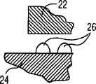
声学组件20安装于柔性电路16的第一平面部分16a的上表面上。尽管声学组件20可以是用于传输和接收超声波的任何已知类型的,但是在优选的实施例中,声学组件20包括许多连接于连接器垫上的声学元件22或者利用倒装互连技术位于集成电路24的上表面上,这些具体的细节对本发明所属领域的普通技术人员而言是众所周知。声学元件22与集成电路24之间的互连的数量可以根据声学元件22的数量和声学元件22及集成电路24的尺寸与形状而变,并且甚至可以大约高达3000。声学元件22可以设置于线性阵列中,即设置于声学元件的直线中以便提供一维换能器,或者设置于多维阵列中,例如设置于声学元件的两维矩阵中以便提供二维换能器。声学组件20可以是平面式或弯曲式。The
用于将声学元件22连接于集成电路24上的其它方法包括使用金属、焊料或聚合物隆起26(如图3和4中所示)、细线接合、z轴导电弹性连接器、z轴导电粘合剂、z轴导电薄膜和回流焊料。在图3中,隆起26形成于集成电路24上,而在图4中,隆起26形成于声学元件22上,开口28形成于集成电路24的上表面中以便能够与集成电路24中的导电层接触。还可以使用反向倒装互连技术。Other methods for attaching the
如图5中所示,集成电路24通过导线结合连接于柔性电路16上,即柔性电路16上的连接点或连接器垫30通过短导线34(也称作导线结合)连接于在集成电路24上表面的连接点或连接器垫32上。因此,电连接装置,即用于声学元件22和柔性电路16的连接器垫或连接点均设置于集成电路24的上表面上。尽管如此,但是在其它实施例中连接装置可以设置于不同表面上。As shown in FIG. 5 , the
柔性电路16与集成电路24之间的导线结合可以全部绕着集成电路24的周边来提供,或如图5所示,只是沿着周边的一个或多个离散部分来提供。更具体而言,如图5所示,在集成电路24的一对相对侧上具有两行导线结合(也称作双行)。通过只在集成电路24的一对相对侧上具有多行导线结合,就为换能器10提供了更符合人机工程学的设计,即更窄的换能器。The wire bonds between
代替导线结合,导线附连装置或引线的接头结合可以提供于连接器垫30与连接器垫32之间。Instead of wire bonding, wire attachment means or terminal bonding of leads may be provided between the
优选地,集成电路24的位置尽可能靠近主体14以便提供至主体14的短传热路径。在在集成电路24与主体14之间的短传热路径使得由集成电路24所产生的热能够被传输至主体14从而消散。因此,主体14用作散热器,并因此由具有良好导热性的材料如铜、铝、黄铜、石墨及其混合物或其它导热材料制成。Preferably, the
在图6所示的一个实施例中,集成电路24与主体14直接接触,从而提供可能最短的传热路径。这样就使得绕着集成电路24形成柔性电路16成为可能。In one embodiment shown in FIG. 6, the
用于操作与控制换能器10所需的电子操作部件36按照本领域的任何已知方式例如通过表面安装来安装于柔性电路16的第二平面部分16b上,从而使得部件36位于腔18中。通常,可能具有十个或更多个这种部件。因此,部件36位于腔18中并且不会伸出主体14的下表面。应当指出,由于柔性电路16绕着主体14弯曲,所以在换能器10的制造过程中(以下所述)声学组件20与部件36安装于柔性电路16的同一侧上。The
当柔性电路16弯曲时,就减少了换能器10的垂直尺寸。在一个实施例中,柔性电路16可以弯曲直至柔性电路16(绕着主体14弯曲)、声学元件22和集成电路24的组合的垂直尺寸小于集成电路24的水平长度的百分之七十五,乃至小于百分之五十。When
为了将柔性电路16连接于从检查装置通往相关联设备如监控与记录装置的多条同轴导线38上,就使用了一对附加柔性电路40、42,其中每个附加柔性电路都具有用于同轴导线38的适当连接装置,例如连接点或连接器垫44。同轴导线38的数量可以根据换能器10的应用情况而不同,但是可以高达160乃至200。每个柔性电路40、42通过将同轴导线38的裸露传导部分38a结合至柔性电路40、42的连接点上而连接于同轴导线38的一部分上,例如使用已知的结合法来实现。柔性电路40、42可以整体都具有柔性或者具有柔性部分和刚性部分,甚至可以整体都具有刚性。In order to connect the
将同轴导线38连接于柔性电路40、42上的操作可以与带有声学组件20和任选电子部件36的柔性电路16的制造分开进行。考虑到具有许多同轴导线38,这样就提供了明显的优点,因为其能够使得柔性电路16及相关元件部分的制造,与用于将柔性电路16连接于外部装置(同轴导线38和柔性电路40、42)上的连接机构的制造分开。The operation of attaching the
柔性电路40、42使用电互连如z轴导电薄膜或导电粘合剂46而连接于柔性电路16上。按照这种方式,通过柔性电路40、42与粘合剂46就提供了柔性电路16与同轴导线38之间的电连接。代替z轴导电薄膜或粘合剂,还可以使用z轴导电弹性连接器或回流焊料。The
代替将电子部件36安装于柔性电路16上,用于控制声学组件20的电子部件或电子装置可以安装于柔性电路40、42上或同轴导线38远离换能器10的端部上。电子部件还可以被集成入集成电路24中。Instead of mounting the
为了制造换能器10,就形成主体14并形成柔性电路16,然后将柔性电路16切制成所需尺寸以便使得其能够绕着主体14弯曲。在形成柔性电路16的同时或之后,将声学组件20和电子部件36安装于柔性电路16的同一侧。为了使得声学组件20能够安装于柔性电路16上,将粘合剂应用于集成电路24的下侧。对声学组件20与电子部件36的安装位置进行选择以便将声学组件20放置于腔18上并将电子部件36放置于腔18中,如图1所示。然后,通过导线结合34将声学部件20的连接点32连接于柔性电路16的连接点30上。声学组件20可以通过将这组声学元件22安装于集成电路24上并使用倒装互连技术将它们连接而预形成。To manufacture the transducer 10 , the
柔性电路40、42与用于柔性电路16和同轴导线38电连接所需的连接点一起形成,然后例如通过焊接而附连于同轴导线38上。柔性电路40、42还利用z轴导电薄膜或导电粘合剂46来附连于柔性电路16的终端16c、16e上。柔性电路40、42可以先附连于同轴导线38上而后再附连于柔性电路16上,反之亦然。The
一旦声学组件20、电子部件36和柔性电路40、42(优选地带有附连于其上的同轴导线38)附连于柔性电路16上,就将粘合剂应用于柔性电路16将与主体14接触的那部分上(并且/或者应用于柔性电路16将靠着主体14的那部分上),而后柔性电路16绕着主体14弯曲以便使得具有安装于其上的声学组件20的柔性电路的平面部分16a位于主体14的支承部分14a上,使得具有安装于其上的电子部件36的平面部分16b位于主体14的腔18中,并使得具有附连于其上的柔性电路40、42的终端部分16c、16e位于主体14的下面。此外,柔性电路16在主体14上进行弯曲以便使得柔性电路16的弯曲16d部分地位于主体14的腿部14b上,使得弯曲16f部分地位于主体14的腔18内,使得弓形部分16g位于腔18中并使得弯曲16h位于主体14的腿部14c上。因此,声学组件20、电子部件36与将柔性电路16连接于同轴导线38上的连接机构都沿垂直方向彼此分开地位于垂直结构设置中,从而就减少了换能器的水平尺寸。实际上,可以从图5中看出,换能器10的尺寸并不大于集成电路24的尺寸。于是就提供了可以装配于经食道的检查装置的顶端(如图1中所示的线12)中的紧凑型换能器。Once the
图7和8示出了根据本发明的换能器的另一实施例。在这个实施例中,所提供的另一个柔性电路48具有用于同轴导线38的适当连接如连接点或连接器垫。柔性电路48通过将同轴导线38的裸露传导部分结合至柔性电路48的连接点上而连接于同轴导线38的一部分上,例如使用已知的结合法来实现。柔性电路48可以整体都具有柔性或者具有柔性部分和刚性部分,甚至可以整体都具有刚性。将同轴导线38连接于柔性电路48上的操作可以与带有声学组件20和任选电子部件36的柔性电路48的制造分开进行。7 and 8 show another embodiment of a transducer according to the invention. In this embodiment, another flexible circuit 48 is provided with suitable connections for the
由于具有三个柔性电路40、42、48,所以在每个电路40、42、48上的同轴导线38的数量小于只提供两个柔性电路40、42时的数量(假定同轴导线38的总量相同),从而就进一步减少了换能器10的厚度。Since there are three
柔性电路48使用电互连如z轴导电薄膜或导电粘合剂46而连接于柔性电路16上。更具体而言,柔性电路48连接于柔性电路16的侧翼部分16k,该侧翼部分16k通过180°弯曲16j与柔性电路的第二平面部分16b的一个侧缘隔开。为了进一步减少了换能器10的厚度,可以提供从柔性电路16的第二平面部分16b的另一个侧缘延伸的另一个侧翼。还可以设想所使用的柔性电路16可以只从柔性电路16的一个或两个平面部分的侧缘延伸。Flex circuit 48 is attached to flex
图9示出了根据本发明的换能器的另一实施例。在这个实施例中,换能器50包括导热主体52和绕着主体52弯曲的柔性电路54。通过提供柔性电路54并将换能器50工作所必须的部件联接于柔性电路54上,可以将柔性电路54弯曲成所需形状以便使得其能够安装于检查装置的尖端12内。Fig. 9 shows another embodiment of a transducer according to the invention. In this embodiment, the transducer 50 includes a thermally conductive body 52 and a flex circuit 54 that bends around the body 52 . By providing a flexible circuit 54 and coupling the components necessary for the operation of the transducer 50 to the flexible circuit 54, the flexible circuit 54 can be bent into a desired shape to enable it to fit within the
主体52具有中央支承部分52a和各位于支承部分52a两端的腿部52b、52c,其中柔性电路54由支承部分52a支承并在腿部52b、52c上面弯曲。腔58形成于在支承部分52a下面的主体52的下侧。The main body 52 has a central support portion 52a and leg portions 52b, 52c at each end of the support portion 52a, wherein the flexible circuit 54 is supported by the support portion 52a and bent over the legs 52b, 52c. A cavity 58 is formed on the lower side of the main body 52 below the support portion 52a.
柔性电路54具有面向腔58的第一终端平面部分54a、位于主体52的支承部分52a上的第二平面部分54b、通过一百八十度(180°)弯曲54d与第二平面部分54b隔开的终端54c和将第一终端平面部分54a与第二平面部分54b隔开的一百八十度(180°)弯曲54e。终端54c基本为平面并且位于主体52的下方。一百八十度(180°)弯曲54d、54e可以包括通过如图9中所示的直形部分隔开的一对九十度(90°)弯曲或者整个为弓形。弯曲的形式可以部分取决于主体52的形状。The flex circuit 54 has a first terminal planar portion 54a facing the cavity 58, a second planar portion 54b positioned on the support portion 52a of the body 52, and separated from the second planar portion 54b by a one-eighty-degree (180°) bend 54d. A terminal 54c and a one-hundred-eighty-degree (180°) bend 54e separating the first terminal planar portion 54a from the second planar portion 54b. Terminal 54c is substantially planar and is located below body 52 . One hundred eighty degree (180°) bends 54d, 54e may include a pair of ninety degree (90°) bends separated by a straight portion as shown in FIG. 9 or be entirely arcuate. The form of the curvature may depend in part on the shape of the body 52 .
柔性电路54并不需要在其整个长度上都具有柔性来实现本发明的目的,但是当然应当满足至少被弯曲的那些部分具有柔性。柔性电路54未被弯曲的其它部分,例如支承着下面所述的换能器50的部件的那些平面部分可以具有刚性。声学组件20安装于柔性电路54的第二平面部分54b的上表面上,并且在所示的优选实施例中,声学组件20包括一阵列声学元件22和集成电路24。声学组件20安装于柔性电路54上的操作可以与声学组件20安装于上述柔性电路16上的操作相同,即通过导线结合34将柔性电路54的连接点30连接于集成电路24的连接点32上来完成。柔性电路54可以具有开口以便能够使得集成电路24与主体52直接接触。The flex circuit 54 does not need to be flexible over its entire length to achieve the purposes of the present invention, but it should of course suffice that at least those portions that are bent be flexible. Other portions of the flexible circuit 54 that are not bent, such as those planar portions that support the components of the transducer 50 described below, may be rigid.
用于操作与控制换能器50所需的电子部件36安装于第一平面部分54a上,从而使得部件36位于腔58中。于是,所形成的腔58具有设计成用于容放电子部件36的形状。应当指出,由于柔性电路54绕着主体52弯曲,所以在换能器50的制造过程中(以下所述)声学组件20与部件36安装于柔性电路54的相对侧上。The
为了将柔性电路54连接于从检查装置通往相关联设备如监控与记录装置的多条同轴导线38上,就使用了附加柔性路60,其中附加柔性电路具有用于同轴导线38的适当连接装置,例如连接点或连接器垫。柔性电路60具有U形部分60a和具有两个平面段的V形部分60b,其中U形部分的一条腿与柔性电路54的终端54c相对,而另一条腿与柔性电路54的第一平面部分54a相对。V形部分60的平面段通过将同轴导线38的裸露传导部分38a结合至柔性电路60的连接点上而连接于同轴导线38上,例如使用已知的结合法来实现。柔性电路60可以整体都具有柔性或者具有一个或多个柔性部分和一个或多个刚性部分。In order to connect the flexible circuit 54 to the plurality of
柔性电路60使用电互连如z轴导电薄膜或导电粘合剂62而连接于柔性电路54上(柔性电路54的终端54c连接于柔性电路60的U形部分60a的对应腿上)。按照这种方式,通过柔性电路60与粘合剂62就提供了柔性电路54与同轴导线38之间的电连接。代替z轴导电薄膜或粘合剂,还可以使用z轴导电弹性连接器或回流焊料。Flex circuit 60 is attached to flex circuit 54 using an electrical interconnect such as a z-axis conductive film or conductive adhesive 62 (terminals 54c of flex circuit 54 are attached to corresponding legs of U-shaped portion 60a of flex circuit 60). In this manner, electrical connection between the flexible circuit 54 and the
代替将电子部件36安装于柔性电路54上,用于控制声学组件20的电子部件或电子装置可以安装于柔性电路60上或同轴导线38远离换能器10的端部上。电子部件还可以被集成入集成电路24中。Instead of mounting the
为了制造换能器50,就形成主体52并形成柔性电路54,然后将柔性电路54切制成所需尺寸以便使得其能够绕着主体52弯曲。在形成柔性电路54的同时或之后,将声学组件20和电子部件36安装于柔性电路54的相对侧。为了使得声学组件20能够安装于柔性电路54上,将粘合剂应用于集成电路24的下侧。对声学部件20与电子部件36的安装位置进行选择以便将声学组件20放置于腔58上并将电子部件36放置于腔58中,如图9所示。利用导线结合34可将声学组件20的连接点连接于柔性电路54的连接点上。声学组件20可以通过将一组声学元件22安装于集成电路24上并使用倒装互连技术将它们连接而预形成。To manufacture transducer 50 , body 52 is formed and flex circuit 54 is formed, and flex circuit 54 is cut to size so that it can be bent around body 52 . At the same time as or after forming the flexible circuit 54 , the
柔性电路60与用于柔性电路54和同轴导线38电连接所需的连接点一起形成,然后附连于同轴导线38上。柔性电路60还利用z轴导电薄膜或导电粘合剂62来附连于柔性电路54的终端54c上。柔性电路70可以先附连于同轴导线38上而后再附连于柔性电路54上,反之亦然。The flex circuit 60 is formed with the required connection points for the electrical connection of the flex circuit 54 to the
一旦声学组件20、电子部件36和柔性电路60(优选地带有附连于其上的同轴导线38)附连于柔性电路54上,就将粘合剂应用于柔性电路54将与主体52接触的那部分上(并且/或者应用于柔性电路54将靠着主体52的那部分上),而后柔性电路54绕着主体52弯曲以便使得具有安装于其上的声学组件20的柔性电路54的平面部分54b位于主体52的支承部分52a上,使得具有安装于其上的电子部件36的平面部分54a位于主体52的腔58下面,并使得具有附连于其上的柔性电路60的终端部分54c位于主体52的下面,其中电子部件36位于腔58中。此外,柔性电路54在主体52上进行弯曲以便使得柔性电路54的弯曲54d部分地位于主体52的腿部52b上并且使得弯曲54e位于主体52的腿部52c上。因此,声学组件20、电子部件36与将柔性电路54连接于同轴导线38上的连接机构都位于垂直结构设置中,从而就减少了换能器的水平尺寸。于是就提供了可以装配于经食道的检查装置的顶端(如图9中所示的线12)中的紧凑型换能器。Once the
附图中所示的这些实施例都使用同轴导线38。然而,本发明还设想使用其它类型的信号传输线路,包括但是并不限于扁平带状缆线或长柔性电路。用于本发明的信号传输线路包括将会电联接于柔性电路的连接点上的导电元件。The embodiments shown in the figures all use
尽管本文中已经参看附图对本发明的所示实施例进行了描述,但是应该理解本发明并不限于这些的准确实施例,在不背离本发明的范围及精神实质的情况下,本发明所属领域的普通技术人员对本发明可以做出多种其它变动与变型。Although illustrated embodiments of the present invention have been described herein with reference to the accompanying drawings, it should be understood that the invention is not limited to these precise embodiments, and that the invention pertains without departing from the scope and spirit of the invention. Those of ordinary skill in the art can make many other changes and modifications to the present invention.
Claims (27)
Translated fromChineseApplications Claiming Priority (2)
| Application Number | Priority Date | Filing Date | Title |
|---|---|---|---|
| US43253602P | 2002-12-11 | 2002-12-11 | |
| US60/432,536 | 2002-12-11 |
Related Child Applications (1)
| Application Number | Title | Priority Date | Filing Date |
|---|---|---|---|
| CNA2007101938438ADivisionCN101172046A (en) | 2002-12-11 | 2003-11-24 | Miniaturized ultrasonic transducer |
Publications (2)
| Publication Number | Publication Date |
|---|---|
| CN1725982Atrue CN1725982A (en) | 2006-01-25 |
| CN100435741C CN100435741C (en) | 2008-11-26 |
Family
ID=32507952
Family Applications (2)
| Application Number | Title | Priority Date | Filing Date |
|---|---|---|---|
| CNA2007101938438APendingCN101172046A (en) | 2002-12-11 | 2003-11-24 | Miniaturized ultrasonic transducer |
| CNB2003801059873AExpired - Fee RelatedCN100435741C (en) | 2002-12-11 | 2003-11-24 | Miniaturized ultrasonic transducer |
Family Applications Before (1)
| Application Number | Title | Priority Date | Filing Date |
|---|---|---|---|
| CNA2007101938438APendingCN101172046A (en) | 2002-12-11 | 2003-11-24 | Miniaturized ultrasonic transducer |
Country Status (6)
| Country | Link |
|---|---|
| US (1) | US20060116584A1 (en) |
| EP (1) | EP1575429A1 (en) |
| JP (1) | JP2006510269A (en) |
| CN (2) | CN101172046A (en) |
| AU (1) | AU2003280172A1 (en) |
| WO (1) | WO2004052209A1 (en) |
Cited By (5)
| Publication number | Priority date | Publication date | Assignee | Title |
|---|---|---|---|---|
| CN101495247B (en)* | 2006-07-24 | 2011-11-23 | 皇家飞利浦电子股份有限公司 | Ultrasonic transducer featuring a pitch independent interposer and method of making the same |
| CN101517737B (en)* | 2006-09-25 | 2012-10-31 | 皇家飞利浦电子股份有限公司 | Flip Chip Interconnection Through Chip Vias |
| CN108618809A (en)* | 2017-03-22 | 2018-10-09 | 精工爱普生株式会社 | Ultrasonic device unit, ultrasonic probe and ultrasonic unit |
| CN109414252A (en)* | 2016-06-30 | 2019-03-01 | 富士胶片株式会社 | Ultrasonic endoscope |
| CN110381844A (en)* | 2017-03-02 | 2019-10-25 | 皇家飞利浦有限公司 | Ultrasound equipment |
Families Citing this family (28)
| Publication number | Priority date | Publication date | Assignee | Title |
|---|---|---|---|---|
| US8641627B2 (en)* | 2003-11-26 | 2014-02-04 | Imacor Inc. | Transesophageal ultrasound using a narrow probe |
| US20090309217A1 (en)* | 2006-06-26 | 2009-12-17 | Koninklijke Philips Electronics N.V. | Flip-chip interconnection with a small passivation layer opening |
| EP2036125B1 (en)* | 2006-06-26 | 2019-05-22 | Koninklijke Philips N.V. | Flip-chip interconnection with formed couplings |
| US20080058597A1 (en)* | 2006-09-06 | 2008-03-06 | Innurvation Llc | Imaging and Locating Systems and Methods for a Swallowable Sensor Device |
| US20080112885A1 (en) | 2006-09-06 | 2008-05-15 | Innurvation, Inc. | System and Method for Acoustic Data Transmission |
| EP2063766B1 (en) | 2006-09-06 | 2017-01-18 | Innurvation, Inc. | Ingestible low power sensor device and system for communicating with same |
| WO2009027522A1 (en) | 2007-08-30 | 2009-03-05 | Oslo Universitetssykehus Hf | Automated monitoring of myocardial function by ultrasonic transducers positioned on the heart |
| US9197470B2 (en) | 2007-10-05 | 2015-11-24 | Innurvation, Inc. | Data transmission via multi-path channels using orthogonal multi-frequency signals with differential phase shift keying modulation |
| US8617058B2 (en) | 2008-07-09 | 2013-12-31 | Innurvation, Inc. | Displaying image data from a scanner capsule |
| RU2547165C2 (en) | 2008-12-23 | 2015-04-10 | Конинклейке Филипс Электроникс Н.В. | Integrated circuit with suppression of spurious acoustic modes and method of producing same |
| US8207652B2 (en)* | 2009-06-16 | 2012-06-26 | General Electric Company | Ultrasound transducer with improved acoustic performance |
| US8345508B2 (en) | 2009-09-20 | 2013-01-01 | General Electric Company | Large area modular sensor array assembly and method for making the same |
| US9192353B2 (en)* | 2009-10-27 | 2015-11-24 | Innurvation, Inc. | Data transmission via wide band acoustic channels |
| JP5039167B2 (en)* | 2010-03-24 | 2012-10-03 | 株式会社東芝 | Two-dimensional array ultrasonic probe and probe diagnostic apparatus |
| US8647259B2 (en) | 2010-03-26 | 2014-02-11 | Innurvation, Inc. | Ultrasound scanning capsule endoscope (USCE) |
| JP5826478B2 (en)* | 2010-10-28 | 2015-12-02 | 日立アロカメディカル株式会社 | Tissue insertion type ultrasonic probe |
| JP2014057136A (en)* | 2012-09-11 | 2014-03-27 | Hitachi Aloka Medical Ltd | Ultrasonic probe |
| US9949739B2 (en)* | 2013-02-27 | 2018-04-24 | Microvention, Inc. | Integral wiping system and method |
| US8959998B2 (en)* | 2013-05-15 | 2015-02-24 | Air Products And Chemicals, Inc. | Ultrasonic liquid level sensing systems |
| US10151618B2 (en) | 2014-01-24 | 2018-12-11 | Versum Materials Us, Llc | Ultrasonic liquid level sensing systems |
| CN107106136B (en)* | 2015-01-13 | 2020-09-22 | 皇家飞利浦有限公司 | Interposer electrical interconnect coupling methods, apparatus, and systems |
| EP3244801B1 (en)* | 2015-01-13 | 2019-08-14 | Koninklijke Philips N.V. | Interposer electrical interconnect with spring |
| CN107209053B (en)* | 2015-02-03 | 2021-01-08 | 霍尼韦尔国际公司 | Piezoelectric ultrasonic detector |
| TWI669789B (en)* | 2016-04-25 | 2019-08-21 | 矽品精密工業股份有限公司 | Electronic package |
| CN112384148B (en)* | 2018-07-10 | 2025-04-04 | 皇家飞利浦有限公司 | Wire connections in ultrasound imaging devices, systems and methods |
| CN112839591B (en)* | 2018-10-19 | 2024-11-15 | 奥林巴斯株式会社 | Ultrasonic probes and ultrasonic endoscopes |
| US12114863B2 (en) | 2018-12-05 | 2024-10-15 | Microvention, Inc. | Implant delivery system |
| US11656355B2 (en) | 2020-07-15 | 2023-05-23 | Siemens Medical Solutions Usa, Inc. | Direct chip-on-array for a multidimensional transducer array |
Family Cites Families (11)
| Publication number | Priority date | Publication date | Assignee | Title |
|---|---|---|---|---|
| US4977898A (en)* | 1988-02-25 | 1990-12-18 | Hoffrel Instruments, Inc. | Miniaturized encapsulated ultrasonic transducer |
| NL9001755A (en)* | 1990-08-02 | 1992-03-02 | Optische Ind De Oude Delft Nv | ENDOSCOPIC SCANNER. |
| US5429136A (en)* | 1993-04-21 | 1995-07-04 | Devices For Vascular Intervention, Inc. | Imaging atherectomy apparatus |
| US5452267A (en)* | 1994-01-27 | 1995-09-19 | Magnetrol International, Inc. | Midrange ultrasonic transducer |
| US5560362A (en)* | 1994-06-13 | 1996-10-01 | Acuson Corporation | Active thermal control of ultrasound transducers |
| US5857974A (en)* | 1997-01-08 | 1999-01-12 | Endosonics Corporation | High resolution intravascular ultrasound transducer assembly having a flexible substrate |
| US5947905A (en)* | 1997-10-15 | 1999-09-07 | Advanced Coronary Intervention, Inc. | Ultrasound transducer array probe for intraluminal imaging catheter |
| US6113546A (en)* | 1998-07-31 | 2000-09-05 | Scimed Life Systems, Inc. | Off-aperture electrical connection for ultrasonic transducer |
| US6551248B2 (en)* | 2001-07-31 | 2003-04-22 | Koninklijke Philips Electronics N.V. | System for attaching an acoustic element to an integrated circuit |
| EP1414347A1 (en)* | 2001-07-31 | 2004-05-06 | Koninklijke Philips Electronics N.V. | Transesophageal and transnasal, transesophageal ultrasound imaging systems |
| US7022080B2 (en)* | 2002-06-27 | 2006-04-04 | Acuson Corporation | Electrical and mechanical enhancements for a modular transducer system |
- 2003
- 2003-11-24USUS10/537,891patent/US20060116584A1/ennot_activeAbandoned
- 2003-11-24CNCNA2007101938438Apatent/CN101172046A/enactivePending
- 2003-11-24EPEP03772542Apatent/EP1575429A1/ennot_activeWithdrawn
- 2003-11-24AUAU2003280172Apatent/AU2003280172A1/ennot_activeAbandoned
- 2003-11-24WOPCT/IB2003/005418patent/WO2004052209A1/enactiveApplication Filing
- 2003-11-24CNCNB2003801059873Apatent/CN100435741C/ennot_activeExpired - Fee Related
- 2003-11-24JPJP2004558908Apatent/JP2006510269A/enactivePending
Cited By (8)
| Publication number | Priority date | Publication date | Assignee | Title |
|---|---|---|---|---|
| CN101495247B (en)* | 2006-07-24 | 2011-11-23 | 皇家飞利浦电子股份有限公司 | Ultrasonic transducer featuring a pitch independent interposer and method of making the same |
| CN101517737B (en)* | 2006-09-25 | 2012-10-31 | 皇家飞利浦电子股份有限公司 | Flip Chip Interconnection Through Chip Vias |
| CN109414252A (en)* | 2016-06-30 | 2019-03-01 | 富士胶片株式会社 | Ultrasonic endoscope |
| CN109414252B (en)* | 2016-06-30 | 2021-05-11 | 富士胶片株式会社 | Ultrasonic endoscope |
| US11076838B2 (en) | 2016-06-30 | 2021-08-03 | Fujifilm Corporation | Ultrasonic endoscope |
| CN110381844A (en)* | 2017-03-02 | 2019-10-25 | 皇家飞利浦有限公司 | Ultrasound equipment |
| CN110381844B (en)* | 2017-03-02 | 2023-04-04 | 皇家飞利浦有限公司 | Ultrasound device |
| CN108618809A (en)* | 2017-03-22 | 2018-10-09 | 精工爱普生株式会社 | Ultrasonic device unit, ultrasonic probe and ultrasonic unit |
Also Published As
| Publication number | Publication date |
|---|---|
| AU2003280172A1 (en) | 2004-06-30 |
| JP2006510269A (en) | 2006-03-23 |
| WO2004052209A1 (en) | 2004-06-24 |
| EP1575429A1 (en) | 2005-09-21 |
| CN100435741C (en) | 2008-11-26 |
| CN101172046A (en) | 2008-05-07 |
| US20060116584A1 (en) | 2006-06-01 |
Similar Documents
| Publication | Publication Date | Title |
|---|---|---|
| CN1725982A (en) | Miniaturized Ultrasonic Transducer | |
| US7791252B2 (en) | Ultrasound probe assembly and method of fabrication | |
| US10312566B2 (en) | Cable connection structure and endoscope device | |
| US10653306B2 (en) | Electronic circuit unit, imaging unit, and endoscope | |
| US6497667B1 (en) | Ultrasonic probe using ribbon cable attachment system | |
| US20170224306A1 (en) | High frequency ultrasound probe | |
| JP2014502201A (en) | Ultrasonic device forming method and related apparatus | |
| CN105101864A (en) | Endoscope device | |
| US12370576B2 (en) | Chip-on-array with interposer for a multidimensional transducer array | |
| CN1802036A (en) | Ultrasonic probe | |
| US20230291988A1 (en) | Image pickup unit, method of manufacturing image pickup unit, and endoscope | |
| CN104838671A (en) | Connection structure for semiconductor device, ultrasonic module, and ultrasonic endoscope system having built-in ultrasonic module | |
| CN109259795B (en) | Method for bonding intermediate member and integrated circuit chip and ultrasonic probe using the same | |
| US9919343B2 (en) | Ultrasound transducer and ultrasound endoscope | |
| JP2001198126A (en) | Ultrasonic probe and manufacturing method thereof | |
| US7400513B2 (en) | Conductive printed board, multicore cable and ultrasonic probe using the same | |
| JPH07131896A (en) | Ultrasonic probe and manufacturing method thereof | |
| US12028597B2 (en) | Image pickup apparatus and endoscope | |
| US11955498B2 (en) | Image pickup apparatus, endoscope, and method of manufacturing image pickup apparatus | |
| US20060253027A1 (en) | Redundant wire bonds for increasing transducer reliability | |
| JP7370559B2 (en) | Circuit boards, board modules, and device modules | |
| JP2002315751A (en) | Ultrasonic probe |
Legal Events
| Date | Code | Title | Description |
|---|---|---|---|
| C06 | Publication | ||
| PB01 | Publication | ||
| C10 | Entry into substantive examination | ||
| SE01 | Entry into force of request for substantive examination | ||
| C14 | Grant of patent or utility model | ||
| GR01 | Patent grant | ||
| C17 | Cessation of patent right | ||
| CF01 | Termination of patent right due to non-payment of annual fee | Granted publication date:20081126 Termination date:20091224 |