CN1711550A - capacitive target sensor - Google Patents
capacitive target sensorDownload PDFInfo
- Publication number
- CN1711550A CN1711550ACNA2003801030235ACN200380103023ACN1711550ACN 1711550 ACN1711550 ACN 1711550ACN A2003801030235 ACNA2003801030235 ACN A2003801030235ACN 200380103023 ACN200380103023 ACN 200380103023ACN 1711550 ACN1711550 ACN 1711550A
- Authority
- CN
- China
- Prior art keywords
- electric field
- field sensing
- electrode
- sensing
- emitting
- Prior art date
- Legal status (The legal status is an assumption and is not a legal conclusion. Google has not performed a legal analysis and makes no representation as to the accuracy of the status listed.)
- Granted
Links
Images


Classifications
- G—PHYSICS
- G01—MEASURING; TESTING
- G01R—MEASURING ELECTRIC VARIABLES; MEASURING MAGNETIC VARIABLES
- G01R29/00—Arrangements for measuring or indicating electric quantities not covered by groups G01R19/00 - G01R27/00
- G01R29/12—Measuring electrostatic fields or voltage-potential
- G—PHYSICS
- G01—MEASURING; TESTING
- G01R—MEASURING ELECTRIC VARIABLES; MEASURING MAGNETIC VARIABLES
- G01R23/00—Arrangements for measuring frequencies; Arrangements for analysing frequency spectra
- G01R23/02—Arrangements for measuring frequency, e.g. pulse repetition rate; Arrangements for measuring period of current or voltage
- G01R23/12—Arrangements for measuring frequency, e.g. pulse repetition rate; Arrangements for measuring period of current or voltage by converting frequency into phase shift
- G—PHYSICS
- G01—MEASURING; TESTING
- G01R—MEASURING ELECTRIC VARIABLES; MEASURING MAGNETIC VARIABLES
- G01R27/00—Arrangements for measuring resistance, reactance, impedance, or electric characteristics derived therefrom
- G01R27/02—Measuring real or complex resistance, reactance, impedance, or other two-pole characteristics derived therefrom, e.g. time constant
- G01R27/26—Measuring inductance or capacitance; Measuring quality factor, e.g. by using the resonance method; Measuring loss factor; Measuring dielectric constants ; Measuring impedance or related variables
- G—PHYSICS
- G06—COMPUTING OR CALCULATING; COUNTING
- G06F—ELECTRIC DIGITAL DATA PROCESSING
- G06F3/00—Input arrangements for transferring data to be processed into a form capable of being handled by the computer; Output arrangements for transferring data from processing unit to output unit, e.g. interface arrangements
- G06F3/01—Input arrangements or combined input and output arrangements for interaction between user and computer
- G06F3/03—Arrangements for converting the position or the displacement of a member into a coded form
- G06F3/041—Digitisers, e.g. for touch screens or touch pads, characterised by the transducing means
- G06F3/044—Digitisers, e.g. for touch screens or touch pads, characterised by the transducing means by capacitive means
- G—PHYSICS
- G06—COMPUTING OR CALCULATING; COUNTING
- G06V—IMAGE OR VIDEO RECOGNITION OR UNDERSTANDING
- G06V40/00—Recognition of biometric, human-related or animal-related patterns in image or video data
- G06V40/10—Human or animal bodies, e.g. vehicle occupants or pedestrians; Body parts, e.g. hands
- G06V40/12—Fingerprints or palmprints
- G06V40/13—Sensors therefor
- G06V40/1306—Sensors therefor non-optical, e.g. ultrasonic or capacitive sensing
Landscapes
- Engineering & Computer Science (AREA)
- Physics & Mathematics (AREA)
- General Physics & Mathematics (AREA)
- Theoretical Computer Science (AREA)
- Human Computer Interaction (AREA)
- Multimedia (AREA)
- General Engineering & Computer Science (AREA)
- Measurement Of Length, Angles, Or The Like Using Electric Or Magnetic Means (AREA)
- Image Input (AREA)
Abstract
Description
Translated fromChinese本发明涉及使用电场感测的目标或特征感测。电场感测也称为准静电感测,并且可称之为交叉电容性感测。本发明特别适合于(但不限于)指纹感测。The present invention relates to object or feature sensing using electric field sensing. Electric field sensing is also known as quasi-electrostatic sensing, and may be referred to as cross-capacitive sensing. The invention is particularly suitable for, but not limited to, fingerprint sensing.
用于目标感测的感测技术包括电容性感测和电场感测,电场感测也称为准静电感测,并且还可以称之为交叉电容性感测。使用电场感测来检测三维空间的目标已经公知了很长时间,例如可用于接近式传感器。事实上,象鼻鱼使用电场感测来检测目标。按它的最简单的形式,电容性感测只使用一个电极,并且测量这个电极的负载电容。这个负载电容是通过对于在电极和电极周围的所有接地目标之间的所有电容求和确定的。这就是在接近式感测中所要作的工作。电场感测可以称为交叉电容感测,它使用两个电极,并且有效地测量在这两个电极之间的比电容。可以认为与电场产生设备连接的电极是一个电场感测发射电极,并且可以认为与测量设备连接的电极是一个电场感测接收电极。通过施加一个交变电压可以激励第一电极(发射电极)。由此,因为在电极之间存在电容耦合(即,电场线效应),可以在第二电极(接收电极)中感应出一个位移电流。如果将目标放在这些电极附近(即,在场线内),某些场线被所述目标终止,电容性电流减小。如果监视这个电流,就可以感测目标的存在。Sensing techniques for object sensing include capacitive sensing and electric field sensing, which is also known as quasi-electrostatic sensing and may also be referred to as cross-capacitive sensing. The use of electric field sensing to detect objects in three dimensions has been known for a long time, eg for proximity sensors. In fact, weevils use electric field sensing to detect targets. In its simplest form, capacitive sensing uses only one electrode and measures the load capacitance of this electrode. This load capacitance is determined by summing all capacitances between the electrode and all grounded targets around the electrode. This is what you do in proximity sensing. Electric field sensing, which may be referred to as cross-capacitive sensing, uses two electrodes and effectively measures the specific capacitance between the two electrodes. The electrode connected to the electric field generating device can be considered as an electric field sensing transmitting electrode, and the electrode connected to the measuring device can be considered as an electric field sensing receiving electrode. The first electrode (emitter electrode) can be excited by applying an alternating voltage. Thus, a displacement current can be induced in the second electrode (receiving electrode) because of capacitive coupling (ie, field line effect) between the electrodes. If a target is placed near these electrodes (ie, within the field lines), some of the field lines are terminated by the target and the capacitive current decreases. If this current is monitored, the presence of a target can be sensed.
US-6,025,726公开的是一种电场感测装置的应用,这种电场感测装置尤其是用于计算机和其它应用的一种用户输入设备。所述的电场感测装置根据期望的应用感测用户手指(一根或多根)、手、或整个身体的位置。US-6,025,726 discloses the use of an electric field sensing device, in particular as a user input device for computers and other applications. The electric field sensing device senses the position of the user's finger(s), hand, or entire body depending on the desired application.
诸如在US-6,025,726中公开的装置在所感测的目标位置的精确度或灵敏度方面受到了限制。与对于某些应用所期望的或者所需要的精确度相比(例如指纹感测,这里要求分开感测指纹的各个凸纹的位置),所述装置可达到的精确度达不到这种要求,这是不期望的。Devices such as those disclosed in US-6,025,726 are limited in the accuracy or sensitivity of the sensed target position. The achievable accuracy of the device falls short of the accuracy desired or required for certain applications (such as fingerprint sensing, where the position of the individual ridges of the fingerprint is required to be sensed separately). , which is not expected.
本发明人已经意识到,期望提供一种采用电场感测的目标感测装置,它能提供比常规的装置所能够提供的更局部化的位置感测。这导致对于常规装置的基本限制的分析,即关于电场感测输出如何随距离r下降的灵敏度分布(profile),所述的距离r是距一个理想化的接收器电极的距离。所进行的评估表明,常规的装置在发射和接收电极的后面存在一个接地平面的情况下至多提供的一个这样的灵敏度分布,其中的电场感测输出按照1/r6的关系下降。The present inventors have recognized that it would be desirable to provide an object sensing device employing electric field sensing that provides more localized position sensing than conventional devices are able to provide. This leads to the analysis of a fundamental limitation of conventional devices, namely the sensitivity profile on how the electric field sensing output falls off with distance r from an idealized receiver electrode. Evaluations performed have shown that conventional arrangements, in the presence of a ground plane behind the transmit and receive electrodes, provide at most a sensitivity profile in which the electric field sensing output falls off by 1/r6 .
在第一方面,本发明提供一种使用电场感测的目标或特征感测系统,电场感测还称为准静电感测,还可以称之为交叉电容性感测。这个系统包括至少一个电极装置,每个电极装置包括一个电场感测接收电极和至少两个电场感测发射电极。与驱动其它的电场感测发射电极的交变电压相比,电场感测发射电极之一(或者,在超过两个电场感测发射电极的情况下是一个或多个电场感测发射电极)由一个包括至少某些反相位部分的交变电压来驱动,例如反相信号或其它形式的其特征在于包括相反的极性的信号。In a first aspect, the present invention provides an object or feature sensing system using electric field sensing, also known as quasi-electrostatic sensing, also known as cross-capacitive sensing. The system comprises at least one electrode arrangement, each electrode arrangement comprising an electric field sensing receive electrode and at least two electric field sensing transmit electrodes. One of the electric field sensing emitter electrodes (or, in the case of more than two electric field sensing emitter electrodes, one or more electric field sensing emitter electrodes) is driven by an alternating voltage that drives the other electric field sensing emitter electrodes Driven by an alternating voltage comprising at least some anti-phase components, such as an anti-phase signal or other form of signal characterized by comprising opposite polarities.
这将改善当检测由于目标或特征的存在而在电场感测接收电极中感应的电流的变化时所进行的目标感测的空间精确度。This will improve the spatial accuracy of object sensing when detecting changes in the current induced in the electric field sensing receive electrode due to the presence of an object or feature.
在一个优选安排中,电场感测接收电极是实心的或块形(例如与圆环形形状相反的形状),电场感测发射电极是圆环形式,并且第一电场感测发射电极定位在电场感测接收电极的周围,第二电场感测发射电极定位在第一电场感测发射电极的周围(并且,如果还有一个或多个电场感测发射电极,这个或这些电场感测发射电极要定位在对应的前一个电场感测发射电极的周围,依此类推)。In a preferred arrangement, the electric field sensing receive electrode is solid or block-shaped (e.g. the opposite shape of a circular ring shape), the electric field sensing transmit electrode is in the form of a circular ring, and the first electric field sensing transmit electrode is positioned in the electric field Sensing around the receiving electrode, a second electric field sensing transmitting electrode is positioned around the first electric field sensing transmitting electrode (and, if there is one or more electric field sensing transmitting electrodes, the electric field sensing transmitting electrode(s) positioned around the corresponding previous electric field sensing emitter electrode, and so on).
在一种安排中,两个电场感测发射电极基本上是圆环形式,它们安排在电场感测接收电极的周围,所述的电场感测接收电极基本上是实心圆的形式。In one arrangement, two electric field sensing transmitting electrodes are substantially in the form of circular rings arranged around an electric field sensing receiving electrode substantially in the form of a solid circle.
在另一方面,本发明提供感测目标的方法,所述方法包括提供上述的各项并且对其进行相应的使用。In another aspect, the invention provides a method of sensing an object, the method comprising providing the above and using them accordingly.
具体来说,本发明提供一种感测目标的方法,所述方法包括提供至少一个电极装置,每个电极装置包括一个电场感测接收电极和至少两个电场感测发射电极。所述的方法进一步还包括:与驱动其它的电场感测发射电极的交变电压相比,由一个包括至少某些反相位部分的交变电压来驱动电场感测发射电极之一(或者,在超过两个电场感测发射电极的情况下,驱动一个或多个电场感测发射电极),例如反相信号或其它形式的其特征在于包括相反的极性的信号。Specifically, the present invention provides a method of sensing an object, the method comprising providing at least one electrode arrangement, each electrode arrangement comprising an electric field sensing receiving electrode and at least two electric field sensing transmitting electrodes. The method further includes driving one of the electric field sensing emitter electrodes (or, In the case of more than two electric field-sensing emitter electrodes, one or more electric-field-sensing emitter electrodes are driven), for example with inverted signals or other forms of signals characterized by comprising opposite polarities.
本发明的其它方面如在权利要求书中所要求保护的那样。Other aspects of the invention are as claimed in the claims.
与常规的装置相比,上述的装置和方法提高了局部化位置感测的程度。并且具有改善灵敏度分布的趋势,在有益的实例中,灵敏度分布的改进甚至还可以提高局部化程度,达到电场感测输出按照1/r12关系下降的程度。The above-described devices and methods increase the degree of localized position sensing compared to conventional devices. And there is a tendency to improve the sensitivity distribution, and in beneficial instances, the improvement of the sensitivity distribution can even increase the degree of localization, to the extent that the electric field sensing output falls according to the 1/r12 relationship.
下面参照附图借助于实例描述本发明的实施例,其中:Embodiments of the invention are described below by way of example with reference to the accompanying drawings, in which:
图1表示常规的电场感测系统(不按比例);Figure 1 represents a conventional electric field sensing system (not to scale);
图2是表示图1的系统的常规的电流感测电路的功能模块的方块图;2 is a block diagram representing the functional blocks of a conventional current sensing circuit of the system of FIG. 1;
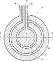
图3表示一个目标感测系统的电极装置(不按比例);Figure 3 shows an electrode arrangement (not to scale) of an object sensing system;
图4表示图3的电极装置,这是通过图3的线X1-X2的横截面图;Figure 4 represents the electrode arrangement of Figure 3, which is a cross-sectional view through line X1-X2 of Figure 3;
图5表示一个目标感测系统;Figure 5 shows an object sensing system;
图6定性地表示提供给某些电场感测发射电极的不同交变电压;Figure 6 qualitatively represents different alternating voltages supplied to certain electric field sensing emitter electrodes;
图7表示一个目标响应曲线的计算结果,该目标响应曲线表示作为目标相对于电场感测接收电极的位置的函数的理论上归一化的信号随,所述电场感测接收电极用于理想的径向对称安排的电场感测电极。Figure 7 shows the results of the calculation of a target response curve representing the theoretically normalized signal response as a function of the position of the target relative to the electric field sensing receive electrode for an ideal Electric field sensing electrodes arranged radially symmetrically.
首先给出常规的电场感测装置的基本操作的梗概说明。图1表示的就是一个常规的电场感测系统1(没按比例画出),所述的电场感测系统包括一个电场感测发射电极2、一个电场感测接收电极4、一个交变电压源6、和一个电流感测电路8。First, an outline description of the basic operation of a conventional electric field sensing device is given. What Fig. 1 represented is exactly a conventional electric field sensing system 1 (not drawn to scale), and described electric field sensing system comprises an electric field sensing transmitting
交变电压源6连接到电场感测发射电极2和电流感测电路8。电流感测电路8单独地连接到电场感测接收电极4。The
在操作中,当将一个交变电压加到电场感测发射电极2时,产生电场线,其中典型的电场线11、12、13通过电场感测接收电极4。电场线11、12、13感生少量的交变电流,这个交变电流是通过电流感测电路8测量的(电流感测电路8使用来自交变电压的一个抽头出的信号以与电场感应电流相位联系起来,下面对此还要进行更加详细地描述)。In operation, when an alternating voltage is applied to the electric field sensing transmitting
当目标10放在两个电极2、4附近的时候,目标中断了这些场线(在如图1所示的情况下,是场线11和12),否则这些场线会通过目标10占据的空间,因此会减小从电场感测接收电极4流出的电流。这样,可以使用由电流感测电路测量的电流电平来作为在两个电极2、4附近目标存在的度量。When the
图2是表示常规的电流感测电路8的功能模块的方块图。电流感测电路8包括一个放大器20、乘法器22、和低通滤波器24。这些功能模块可以用任何合适的形式实施,例如使用在US 6,025,726中公开的电路设计。在这里引用了这个专利的内容以作参照。FIG. 2 is a block diagram showing functional blocks of a conventional
在操作中,在电场感测接收电极4中感应的位移电流26由放大器20放大,并且通过乘法器22与加到电场感测发射电极2的电压的抽头出的并经过相移的(通过一个未示出的相移模块)版本27相乘。所抽头出的电压是经过相移的,因而能使它的相位与位移电流26的相位相同。这样,如果在这里我们假定放大器20是理想的,即不会对位移电流26引入任何附加的相移,则所抽头出的电压的相位移动了90°。如果实际上放大器20的确会对位移电流26引入附加的相移,则要根据适应这种情况的需要来调节所抽头出的电压的相位。In operation, a displacement current 26 induced in the electric field sensing receive
然后对于乘法器22的输出进行低通滤波,以提供输出信号28。于是,输出信号28就是由电场感测发射电极2产生的电场在电场感测接收电极4中感应出来的电流的度量,并且输出信号28将要响应于放在电场感测电极2、4附近的目标10而变化。然后,根据需要通过外部电子装置(未示出)处理所述的输出信号28。The output of multiplier 22 is then low pass filtered to provide output signal 28 . The output signal 28 is then a measure of the current induced in the field-sensing receive
图3表示按照本发明的第一个实施例的目标感测系统的电极装置30(没按比例画出)。所述电极装置包括一个电场感测接收电极32、一个内部电场感测发射电极34、和一个外部电场感测发射电极36。电场感测接收电极具有基本上圆形的形状(即实心圆)。内部电场感测发射电极34基于在电场感测接收电极32的周围的基本上圆环的形状。外部电场感测发射电极36具有在内部电场感测发射电极34的周围的基本上圆环的形状。这样,两个发射电极34、36彼此同心并且与电场感测接收电极32都是同心的。Fig. 3 shows an electrode arrangement 30 (not drawn to scale) of an object sensing system according to a first embodiment of the present invention. The electrode arrangement includes an electric field
如以下所述,这些电极中的每个电极都设有引出或接触部分,因此它们都可以连接到控制电路的各单独部分。电场感测接收电极32设有一个接收电极接触件37。内部电场感测发射电极34设有一个内部发射电极接触件38。外部电场感测发射电极36设有一个外部发射电极接触件39。在圆环形式的每个电场感测发射电极32、34内设有缺口,以使接触件37、38、39能够从装置中引出。应该认识到,可以提供另外的接触件装置取而代之,例如可使用通孔来制成接触件(在这种情况下可以形成完整的圆环)。As described below, each of these electrodes is provided with a lead-out or contact portion so that they can be connected to separate parts of the control circuit. The electric field
为清楚起见,图3没按比例画出,特别是与电极之间的空间相比以及与接触件的宽度相比,这些元件的相对尺寸没按比例画出。本领域的普通技术人员按照若干因素来选择所述元件的尺寸,这些因素包括制造能力、期望感测的目标的典型尺寸。For the sake of clarity, Figure 3 is not drawn to scale, especially the relative dimensions of these elements compared to the spaces between the electrodes and compared to the width of the contacts. One of ordinary skill in the art selects the dimensions of the elements according to several factors, including manufacturability, typical dimensions of the target desired to be sensed.
在这个实施例中,期望这个装置用于指纹感测。在这个实施例中所用的尺寸如下:In this embodiment, it is expected that this device will be used for fingerprint sensing. The dimensions used in this example are as follows:
电场感测接收电极32的半径:40微米;Radius of electric field sensing receiving electrode 32: 40 microns;
内部电场感测发射电极34的内径:60微米;Inner diameter of the internal electric field sensing emitter electrode 34: 60 microns;
内部电场感测发射电极34的外径:73微米;The outer diameter of the internal electric field sensing emitter electrode 34: 73 microns;
外部电场感测发射电极36的内径:93微米;The inner diameter of the external electric field sensing emitter electrode 36: 93 microns;
外部电场感测发射电极36的外径:101微米;The outer diameter of the external electric field sensing emitter electrode 36: 101 microns;
在对应电极之间的环形间隔:20微米和19微米;Annular spacing between corresponding electrodes: 20 microns and 19 microns;
接触件宽度:20微米。Contact width: 20 microns.
图4表示电极装置30的通过图3的线X1-X2的横截面图。如从结合图3的描述可知,如图所示,沿着横截面X1-X2有内部电场感测发射电极34的两个部分和外部电场感测发射电极36的两个部分。如在图4的横截面图中所示的,在电场感测电极32、34、36的下面还提供一个接地平面40。FIG. 4 shows a cross-sectional view of the
可以按照任何方便的方式制造电场感测电极32、34、36和接地平面40。在这里,它们是通过在一个玻璃板(未示出)的上侧淀积电场感测电极32、34、36同时在同一个玻璃板的下侧淀积接地平面40形成的。Electric
图5表示按照本发明的第一个实施例的目标感测系统50。使用相同的附图标记描述与以上所述相同的元件。目标感测系统50包括多个电极装置,每个电极装置都具有以上所述的类型和形状,即包括如图3和4所示的对应的电场感测接收电极32、内部电场感测发射电极34、和外部电场感测发射电极36。对应的电极装置被安排在一个矩阵中。为清楚起见,在图5中只表示出一个这样的电极装置30。还是为清楚起见,只表示出电场感测接收电极32的一部分,并且只表示出内部电场感测发射电极34和外部电场感测发射电极36的两个环形部分(如以上参照附图4所描述的)的每一个环形部分之一(即所示的部分对应于通过图3的线X1-X3的横截面,而不是对应图3的线X1-X2的整体)。FIG. 5 shows an
如图5所示,玻璃板52位于电极装置30的上方。要感测的目标可以定位在玻璃板52上或玻璃板52的附近。在如图5所示的例中,指尖压在玻璃板52上。指尖的指纹轮廓一个凸纹如图5所示,这个凸纹压在玻璃板52上,在电极装置30的附近。因为手指的所有人将他或她的整个指尖压在玻璃板52上,所以其它的指尖凸纹(未示出)同时也压在玻璃板上的其它位置,即对应于电极装置矩阵的其它电极装置。As shown in FIG. 5 , a
电场感测接收电极32和内部电场感测发射电极34按照与以上参照附图1和2所述的相同方式耦合到交变电压源6和电流感测电路8。The electric field sensing receive
交变电压源6还耦合到内部电场感测发射电极36,但要经过一个反相器电路56。The alternating
在电极装置30的下边还包括一个接地平面,这个接地平面对应于上述参照附图4描述的接地平面40,但为清楚起见在图5中没有表示出这个接地平面。这个接地平面对于实现位置局部化的最佳清晰度是优选的,但如果期望的话也可以省去。Also included on the lower side of the
下面参照附图6说明目标感测系统50的操作,图6定性地表示出向内部和外部电场感测发射电极提供的不同交变电压。The operation of the
图6表示交变电压源6输出的并且直接加到内部电场感测发射电极34的交变电压V34的曲线图120。在这个实施例中,这个交变电压是一个+/-10伏和100kHz频率的双极性的方波。在图6中表示的是交变电压V34的周期的正部分122和负部分124。FIG. 6 shows a
反相器电路56使得由交变电压源6提供的交变电压反相,反相的输出被馈送到外部电场感测发射电极36。图6还表示出这个反相的交变电压V36的曲线图130。在图6中表示的是交变电压V36的周期的负部分132和正部分134。The
这样,现在考虑内部和外部电场感测发射电极,显然,当内部电场感测发射电极34正由交变电压V34的周期的正部分122驱动时,外部电场感测发射电极36正由反相电压V36的周期的负部分132驱动。类似地,当内部电场感测发射电极34正由交变电压V34的周期的负部分124驱动时,外部电场感测发射电极36正由反相电压V36的周期的正部分134驱动。换言之,两个发射电极彼此相对地用相反极性的交变电压驱动。这可以称为反相位的操作。Thus, now considering the inner and outer electric field sensing emitter electrodes, it is clear that while the inner electric field
如以上参照附图1和2所述的,由于施加交变电压V34,内部电场感测发射电极34产生电场,这个电场产生从电场感测接收电极32输出的电流26,这个电流26被指纹凸纹54改变。这个电流输入到放大器20并且通过乘法器22与电压V34的抽头出的和移相的版本27相乘,然后经过低通滤波以提供输出信号28。As described above with reference to FIGS. 1 and 2 , due to the application of the alternating voltage V34 , the internal electric field
然而,由于施加反相电压V36,外部电场感测发射电极36也产生电场,这个电场也对从电场感测接收电极32输出的电流26产生贡献,这个贡献被指纹凸纹54改变。因此,在目标感测系统50操作期间,对于电流26的这个贡献也被输入到放大器20,并且通过乘法器22与电压V34的抽头出的和移相的版本27相乘,然后经过低通滤波以便向输出信号28提供它的贡献。However, due to the application of the reverse voltage V36 , the external electric field
由内部电场感测发射电极34产生的对电流26的贡献当由乘法器22相乘时向输出信号28提供一个正的贡献。The contribution to current 26 produced by internal electric field
然而,与加到内部电场感测发射电极34的电压相比,加到外部电场感测发射电极36的电压是反相的。这样,由外部电场感测发射电极36对电流26产生的贡献当由乘法器22相乘时向输出信号28提供一个负的贡献,而不是正的贡献。这样,其效果是,外部电场感测发射电极36的这一贡献改变了由于内部电场感测发射电极34产生的贡献。这种改变因而改善了总的输出信号28对于待感测目标(在这种情况下即指纹凸纹54)相对电场感测接收电极32的位置的依赖性。However, the voltage applied to the outer electric field
于是,提供由反相电压(与如图1所示的常规装置相比)驱动的附加电场感测发射电极36的效果是改善位置感测,因为由附加外部电场感测发射电极36提供的场改变了由于内部电场感测发射电极34提供的场而产生的来自电流感测电路8的感测输出28。The effect of providing an additional electric field
这个效果利用了静电相互作用随距离下降的属性。在接收电极的正上方的电位(或电场强度)主要是由内部发射电极上的电压支配的,因为在所有的方向这个电极是最近的。然而,当离开中心时,来自内部电极的电位(或电场强度)消失得比来自外部发射器电极的贡献(负的)更快,因为后者较大。这就意味着,净信号的下降比其它情况都快。当进一步远高中心时(超越了两个电极),来自内部和另一电极的贡献都趋向于零,总的(净)信号下降到零。因此,通过适当平衡来自内部和外部电极的贡献,可以改变灵敏度分布。This effect takes advantage of the property that electrostatic interactions fall off with distance. The potential (or electric field strength) directly above the receiving electrode is dominated by the voltage on the inner transmitting electrode, since this electrode is closest in all directions. However, when moving away from the center, the potential (or electric field strength) from the inner electrodes disappears faster than the (negative) contribution from the outer emitter electrodes because the latter is larger. This means that the net signal drops faster than it would otherwise. When going further up the center (beyond both electrodes), the contributions from both the inner and the other electrode tend to zero and the total (net) signal drops to zero. Thus, by properly balancing the contributions from the inner and outer electrodes, the sensitivity distribution can be altered.
现在进一步考虑由这些装置提供的位置精确度的程度,所述的位置在平行于电场感测电极32、34、36平面的一个“x-y”平面(即距电极所在平面的固定距离为“z”的平面,这里的x、y、z是垂直轴)中。Considering further now the degree of positional accuracy provided by these devices in an "x-y" plane parallel to the plane of the electric
通过使用数学模型,对于一个理想的径向对称装置,可以计算出一个目标响应曲线,所述的目标响应曲线表示一个作为目标相对于电场感测接收电极的位置的函数的理论上归一化的信号(即,由于目标的存在引起的输出信号28的变化)。更具体来说,考虑一个圆形电场感测接收电极,它具有两个分别提供内部和外部电场感测发射电极的圆形的同心的环。By using a mathematical model, for an ideal radially symmetric device, a target response curve can be calculated that represents a theoretically normalized signal (ie, the change in output signal 28 due to the presence of the target). More specifically, consider a circular electric field sensing receive electrode with two circular concentric rings providing inner and outer electric field sensing transmit electrodes, respectively.
图7表示归一化信号相对于目标位置的一个这样的理论计算结果,目标位置是用相对单位确定的。计算是针对理想情况进行的,其中:Figure 7 shows the result of one such theoretical calculation of the normalized signal relative to the target position, which is determined in relative units. Calculations are performed for the ideal case where:
圆形电场感测接收电极的半径=内部电场感测发射电极的内径=1;The radius of the circular electric field sensing receiving electrode=the inner diameter of the internal electric field sensing transmitting electrode=1;
内部电场感测发射电极的外径=外部电场感测发射电极的内径=1.5;以及Outer diameter of inner electric field sensing emitter electrode = inner diameter of outer electric field sensing emitter electrode = 1.5; and
外部电场感测发射电极的外径=2。The outer diameter of the external electric field sensing emitter electrode=2.
对于指定的一组尺寸,并且对于加到两个电场感测发射电极的两个电压的不同的相对大小,得到归一化信号相对于目标位置的不同结果。(要说明的是,在上述的实施例中加到内部和外部电场感测发射电极这两者的电压大小相同(例如见图6),但也不必是这种情况,在其它的实施例中,如果期望,使用作为反相器电路56的一部分提供的或者在整个系统的其它地方提供的适当的电路,也可以加上不同的电压大小)。图7表示的是根据V36/V34的对应比例(严格地说,是幅度比)等于0.65、0.72、0.75(如图7所示)的情况对于3个不同计算得到的结果。For a given set of dimensions, and for different relative magnitudes of the two voltages applied to the two electric field sensing emitter electrodes, different results are obtained for the normalized signal with respect to the target position. (It should be noted that in the above-described embodiments the voltages applied to both the inner and outer electric field sensing emitter electrodes are of the same magnitude (see, for example, FIG. 6 ), but this need not be the case, and in other embodiments , different voltage magnitudes may also be applied, if desired, using appropriate circuitry provided as part of the
当减小V36/V34的值时(例如V36/V34=0.65),即实际上内部电场感测发射电极占优势时,响应曲线变得平直,并且响应趋向于返回到常规的单个电场感测发射电极装置的情况。When reducing the value of V36 /V34 (e.g. V36 /V34 = 0.65), i.e. when the internal electric field sensing emitter electrode actually dominates, the response curve becomes flattened and the response tends to return to the conventional A single electric field senses the condition of the emitter electrode arrangement.
作为一个推论,当比值V36/V34增加时(例如V36/V34=0.75),响应曲线变得更加尖锐,但还显示出一个负的下跌,即实际上外部电场感测发射电极占优势。As a corollary, when the ratio V36 /V34 is increased (eg V36 /V34 = 0.75), the response curve becomes sharper, but also shows a negative dip, that is, the external electric field sensing emitter electrode actually accounts for Advantage.
于是,对于V36/V34=0.72,实现了最佳的响应(在此例中),因为对于这个值的曲线随距离陡峭地下降但又不包括负的下跌。的确,V36/V34=0.72的曲线对应于1/r12的曲线,比起常规的装置极大地改善了位置精确度。The best response (in this example) is then achieved for V36 /V34 =0.72, since the curve for this value drops off steeply with distance but does not include negative dips. Indeed, the curve of V36 /V34 =0.72 corresponds to the curve of 1/r12 , greatly improving the positional accuracy compared to conventional arrangements.
于是,通过优化或者选择加到两个电场感测发射电极的相对电压的幅度,可以实现或者尝试不同的响应特性。替换地,通过相应地优化或者选择各个电场感测电极的尺寸,也可以实现这一点。另一种替换方案是组合地选择或改变电极尺寸和电压。Thus, by optimizing or selecting the magnitude of the relative voltages applied to the two electric field sensing emitter electrodes, different response characteristics can be achieved or attempted. Alternatively, this can also be achieved by optimizing or selecting the dimensions of the individual electric field sensing electrodes accordingly. Another alternative is to select or vary electrode size and voltage in combination.
在这个实施例中,将多个电极装置30提供在一个矩阵中。按照正在进行的目标感测操作(在本例中是指纹检测和分析),通过另外的控制和处理电路(未示出)以任何合适的方式组合地处理来自每个电极装置30的输出信号28。In this embodiment, a plurality of
上述安排的一个优点是,在进行感测时目标不需要直接放在感测电极上。例如,参照附图5,手指可以压在玻璃板52上,玻璃板52可以与电场感测电极32、34、36分开,因此可以保护这些电极不受物理的和腐蚀的损伤。An advantage of the above arrangement is that the target need not be placed directly on the sensing electrodes for sensing to take place. For example, referring to FIG. 5, a finger can be pressed against a
在上述的实施例中,描述了各个电极的尺寸。也可以按照其它应用的需要使用另外的尺寸。例如,电场感测接收电极、内部电场感测发射电极、和外部电场感测发射电极全可以有彼此不同的半径,或者这些电极中的任何两个电极可以彼此相同,或者所有这三个电极都可以相同。还有,绝对尺寸可以与以上所述的尺寸不同。In the above-described embodiments, the dimensions of the respective electrodes have been described. Additional dimensions may also be used as desired for other applications. For example, the electric-field-sensing receive electrode, the inner electric-field-sensing transmit electrode, and the outer electric-field-sensing transmit electrode may all have different radii from each other, or any two of these electrodes may be identical to each other, or all three electrodes may be Can be the same. Also, the absolute dimensions may differ from those described above.
在上述实施例中,内部电场感测发射电极和外部电场感测发射电极都是围绕中心定位的圆形电场感测接收电极的同心圆环的形式。但是,也可以使用安排成同心的布局的除了环以外的形状。换言之,接收电极可以是任何期望的块形(所谓块形,即与环形相反的实心形状),例如正方形、长方形、三角形、不规则形状等,发射电极则是围绕它的任何期望的环状,外部发射电极是围绕内部发射电极的环状,而内部发射电极本身则要围绕接收电极。In the embodiments described above, both the inner electric field sensing transmit electrode and the outer electric field sensing transmit electrode are in the form of concentric rings surrounding a centrally located circular electric field sensing receive electrode. However, shapes other than rings arranged in a concentric layout may also be used. In other words, the receiving electrode can be any desired block shape (so-called block shape, that is, a solid shape opposite to a ring shape), such as a square, a rectangle, a triangle, an irregular shape, etc., and the transmitting electrode is any desired ring shape around it, The outer transmit electrode is a ring that surrounds the inner transmit electrode, which itself surrounds the receive electrode.
另一种可能性是,提供电场感测接收电极、第一电场感测发射电极、和第二电场感测发射电极,但是它们按照任何便利的方式安排,即不一定非是同心的。在这种情况下,可以采用任何合适的电极布局,加到第二电场感测发射电极的驱动电压在某种程度上是反相的(或完全反相),即与加到第一电场感测发射电极的驱动电压相比是相反的极性或者是反相位的。Another possibility is to provide an electric field sensing receive electrode, a first electric field sensing transmit electrode and a second electric field sensing transmit electrode, but arranged in any convenient way, ie not necessarily concentrically. In this case, any suitable electrode layout can be used, and the driving voltage applied to the second electric field sensing emitter electrode is somewhat antiphase (or completely antiphase), that is, the driving voltage applied to the first electric field sensing electrode. The driving voltage of the emitter electrode is of opposite polarity or phase inversion.
在上述的实施例中,除了第一或常规的电场感测发射电极以外,还要提供一个附加的电场感测发射电极。在另外的实施例中,还可以提供另外的附加的电场感测发射电极,以便进一步改变来自第一常规的电场感测发射电极的输出的位置感测效果。这些另外的附加的电场感测发射电极也由一个驱动电压驱动,这个驱动电压在某种程度上是反相的(或者完全是反相的),即与提供给第一电场感测发射电极的驱动电压相比是相反的极性或者是反相位的。在环形装置的情况下,这些另外的电场感测发射电极可以是另外的环形形状。例如,在第一和第二电场感测发射电极都是圆环形状的情况下,这些另外的电场感测发射电极优选地是另外的环形形状。还有,对于任何一个这样的可能性,可以利用与加到第一电场感测发射电极的驱动电压相同的驱动电压来驱动一个或多个另外的电场感测发射电极。In the above embodiments, besides the first or conventional electric field sensing emitting electrode, an additional electric field sensing emitting electrode is provided. In further embodiments, further additional electric field sensing emitter electrodes may also be provided in order to further vary the position sensing effect of the output from the first conventional electric field sensing emitter electrode. These further additional field-sensing emitter electrodes are also driven by a drive voltage that is somewhat (or completely) inverse to the voltage applied to the first electric-field-sensing emitter electrode. The drive voltages are of opposite polarity or phase inversion. In the case of a ring arrangement, these further electric field sensing emitter electrodes may be of a further ring shape. For example, in case the first and second electric field sensing emitter electrodes are both circular ring shaped, these further electric field sensing emitter electrodes are preferably further ring shaped. Also, for any of these possibilities, one or more further electric field sensing emitter electrodes may be driven with the same drive voltage as applied to the first electric field sensing emitter electrode.
在上述的实施例中,参照附图6描述了驱动电压的形式。在另外的实施例中,可以使用其它的数值和/或形式。例如,另外的幅度可以用于这两个电场感测发射电极或者它们当中的任何一个。类似地,可以使用另外的频率。在上述的实施例中,波形是方波。还可以使用另外的交变波形,例如使用正弦波。In the above-described embodiment, the form of the driving voltage is described with reference to FIG. 6 . In other embodiments, other values and/or formats may be used. For example, additional amplitudes may be used for either or both of the electric field sensing emitter electrodes. Similarly, additional frequencies may be used. In the embodiments described above, the waveform is a square wave. It is also possible to use other alternating waveforms, for example using a sine wave.
在上述的实施例中,加到第二电场感测发射电极的驱动电压在某种程度上是反相的(或完全反相),即与加到第一电场感测发射电极的驱动电压相比是相反的极性或者是反相位的。在上述的实施例中,这就是说,将加到第一电场感测发射电极的驱动电压的交变周期的每个振荡按照相反的形式复制成加到第二电场感测发射电极的驱动电压。然而,将这些驱动电压同时加到这些电极上并不是必要的。低通滤波器24有一个积分时间常数,更加一般的情况是,在这个时间常数内,以相等的时间量驱动两个发射电极,每个电极相对于参考信号27都有正确的(相位或反相位)关系。对于这一点更进一步,另一种可能性是,利用相同的相位来顺序地驱动这些电极,但是在驱动外部电极时,要通过切换入一个附加的相位延迟来改变参考信号的相位。In the above-mentioned embodiments, the driving voltage applied to the second electric field sensing emitter electrode is to some extent inverse (or completely inverse), that is, it is in phase with the driving voltage applied to the first electric field sensing emitter electrode. The ratio is opposite polarity or anti-phase. In the embodiments described above, this means that each oscillation of the alternating period of the drive voltage applied to the first electric field sensing emitter electrode is replicated in reverse form to the drive voltage applied to the second electric field sense emitter electrode . However, it is not essential that these drive voltages be applied to these electrodes simultaneously. The low-pass filter 24 has an integral time constant during which, more generally, both transmit electrodes are driven for an equal amount of time, with each electrode having the correct (phase or opposite phase) relative to the reference signal 27. phase) relationship. Taking this a step further, another possibility is to drive the electrodes sequentially with the same phase, but change the phase of the reference signal by switching in an additional phase delay when driving the outer electrodes.
在上述的实施例中,采用电流感测电路28来感测在电场感测接收电极中感应的位移电流。然而,为此目的还可以使用任何其它合适的电路或装置。一种可能性是,使用形成本申请人的一个待审查专利申请的主题内容的那种类型的电流感测电路,这个待审查的专利申请即美国专利申请No.10/153261,申请人标号为PHGB010089,在这里引用了这个申请的主题内容以作参考。In the above-mentioned embodiments, the current sensing circuit 28 is used to sense the displacement current induced in the electric field sensing receiving electrode. However, any other suitable circuit or arrangement may also be used for this purpose. One possibility is to use a current sensing circuit of the type that forms the subject of a co-pending patent application of the present applicant's, namely U.S. Patent Application No. 10/153,261, Applicant's Serial No. PHGB010089, the subject matter of this application is incorporated herein by reference.
在上述的实施例中,目标感测系统用作指纹感测和分析系统的一部分。然而,本发明不限于这样的应用,本发明还可以用作一个独立的目标感测系统或者合并了目标感测的任何其它的处理和系统的一部分。In the embodiments described above, the object sensing system was used as part of the fingerprint sensing and analysis system. However, the present invention is not limited to such applications, and the present invention can also be used as a stand-alone object sensing system or as part of any other process and system incorporating object sensing.
进而,术语“目标”不限于需要整体感测的分立的目标,相反,这个术语可以包括一个较大的目标的各个特征或元素,这个较大的目标可以逐个地解决或逐个地感测,例如在上述的主要的实施例中所描述的手指的指纹的一个或多个凸纹。一个另外的可能性是,通过感测一个指定的目标的特定特征,可以导出这个指定的目标的取向。Further, the term "object" is not limited to discrete objects requiring sensing as a whole, but rather the term may include individual features or elements of a larger object which may be addressed or sensed individually, e.g. One or more ridges of the fingerprint of a finger as described in the main embodiment above. An additional possibility is that by sensing certain features of a given target, the orientation of the given target can be derived.
可以将目标感测系统合并入一个显示设备或系统中(或与之组合)以便提供一个用户输入或互动装置。例如,可以将目标感测系统合并在一个有源矩阵液晶显示设备的内部,例如沿着在US 5,130,829中公开的液晶显示设备的各行构造并操作,在这里引用了US5,130,829的内容以作参考。在这种情况下,可以使用形成在这里引用以作参考的待审查的美国专利申请No.10/153261的主题内容的这种类型的上述电流感测电路,从而得到特定的好处。The object sensing system may be incorporated into (or combined with) a display device or system to provide a user input or interaction means. For example, an object sensing system may be incorporated within an active matrix liquid crystal display device constructed and operated, for example, along the rows of a liquid crystal display device as disclosed in US 5,130,829, the contents of which are incorporated herein by reference . In this case, a current sensing circuit of the type described above which forms the subject matter of co-pending US Patent Application No. 10/153,261, incorporated herein by reference, may be used to particular advantage.
阅读了本发明的公开内容后,其它的变化和修改对于本领域的普通技术人员来说都显而易见。这样的变化和修改可能涉及到在本领域中已经公知的等效特征和其它特征,可以使用所述的等效特征和其它特征来代替或者补充这里已经描述过的特征。After reading the present disclosure, other changes and modifications will become apparent to those of ordinary skill in the art. Such changes and modifications may involve equivalent and other features already known in the art, which may be used instead of or in addition to features already described herein.
虽然在本申请中已经将权利要求制定成特征的特定组合,但应该理解,本发明的公开内容的范围还包括在这里明显地或隐含地公开的或者经过对其的任何推广而得到的任何新颖的特征或者任何新颍的特征组合,而不管它是否涉及与任何权利要求中要求保护的发明相同的发明,并且不管它是否能解决与本发明所解决的相同的任何或所有的技术问题。Although claims have been made in this application to particular combinations of features, it should be understood that the scope of the present disclosure also includes any and all features disclosed herein, expressly or implicitly, or through any generalization thereof. Novel features or any novel combination of features, regardless of whether it relates to the same invention as claimed in any claim, and regardless of whether it can solve any or all of the same technical problems as the present invention solves.
在各个单独的实施例的内容中描述的特征还可以组合在一起提供在单个实施例中。相反,为简单计而在单个实施例的上下文中描述的各个特征还可以分开提供,或者提供在任何合适的子组合中。本申请的申请人在这里声明:在本申请的审查期间或者是由此导出的任何其它的申请的审查期间,对于这样的特征和/或特征组合可制定出新的权利要求。Features that are described in the context of separate embodiments can also be provided in combination in a single embodiment. Conversely, various features that are, for brevity, described in the context of a single embodiment, may also be provided separately or in any suitable subcombination. The applicant of the present application hereby declares that new claims may be formulated to such features and/or combinations of features during the prosecution of this application or any other application derived therefrom.
Claims (14)
Applications Claiming Priority (2)
| Application Number | Priority Date | Filing Date | Title |
|---|---|---|---|
| GB0226404.2 | 2002-11-12 | ||
| GBGB0226404.2AGB0226404D0 (en) | 2002-11-12 | 2002-11-12 | Object sensing |
Publications (2)
| Publication Number | Publication Date |
|---|---|
| CN1711550Atrue CN1711550A (en) | 2005-12-21 |
| CN100338617C CN100338617C (en) | 2007-09-19 |
Family
ID=9947691
Family Applications (1)
| Application Number | Title | Priority Date | Filing Date |
|---|---|---|---|
| CNB2003801030235AExpired - Fee RelatedCN100338617C (en) | 2002-11-12 | 2003-10-30 | Capacitive object sensor |
Country Status (9)
| Country | Link |
|---|---|
| US (1) | US7339381B2 (en) |
| EP (1) | EP1563447A1 (en) |
| JP (1) | JP2006505785A (en) |
| KR (1) | KR20050074602A (en) |
| CN (1) | CN100338617C (en) |
| AU (1) | AU2003274490A1 (en) |
| GB (1) | GB0226404D0 (en) |
| TW (1) | TW200428294A (en) |
| WO (1) | WO2004044827A1 (en) |
Cited By (5)
| Publication number | Priority date | Publication date | Assignee | Title |
|---|---|---|---|---|
| CN101359906B (en)* | 2007-07-31 | 2010-11-03 | 义隆电子股份有限公司 | Object positioning detector and object positioning method of capacitive touch panel |
| CN102870327A (en)* | 2010-05-07 | 2013-01-09 | 罗伯特·博世有限公司 | Detection of a dielectric object |
| CN102934359A (en)* | 2009-12-11 | 2013-02-13 | 微晶片科技德国第二公司 | Multifunctional touch and/or proximity sensor |
| CN104521143A (en)* | 2012-08-02 | 2015-04-15 | 布罗泽汽车部件制造哈尔施塔特有限公司 | Methods for controlling a capacitive anti-trap system and anti-trap system |
| CN102934359B (en)* | 2009-12-11 | 2016-11-30 | 微晶片科技德国公司 | Multifunctional touching and/or proximity sense |
Families Citing this family (21)
| Publication number | Priority date | Publication date | Assignee | Title |
|---|---|---|---|---|
| DE10252165A1 (en) | 2002-11-09 | 2004-05-19 | Philips Intellectual Property & Standards Gmbh | Communications integrated circuit for implementation of send and receive functions of a network node, especially of a motor vehicle data bus node using the local interconnect network protocol, has an autonomous interface circuit |
| JP4378607B2 (en)* | 2003-08-29 | 2009-12-09 | ソニー株式会社 | measuring device |
| DE102006034778B4 (en) | 2005-07-27 | 2023-11-30 | Microchip Technology Germany Gmbh | Detection device, in particular for implementing a protection system |
| US8057288B2 (en)* | 2008-06-20 | 2011-11-15 | Nissan North America, Inc. | Contact-free vehicle air vent |
| US8212569B1 (en)* | 2008-07-17 | 2012-07-03 | The United States Of America, As Represented By The Secretary Of The Navy | Coupled bi-stable circuit for ultra-sensitive electric field sensing utilizing differential transistor pairs |
| KR101043098B1 (en)* | 2009-12-18 | 2011-06-21 | 연세대학교 산학협력단 | Apparatus and method for measuring distance to object, robot having same |
| KR101157573B1 (en)* | 2010-11-25 | 2012-06-19 | 연세대학교 산학협력단 | Electric sensor system and method of discriminating target object using the same |
| US8547360B2 (en) | 2011-07-08 | 2013-10-01 | National Semiconductor Corporation | Capacitive touch screen sensing and electric field sensing for mobile devices and other devices |
| JP5912727B2 (en)* | 2012-03-23 | 2016-04-27 | 株式会社ワコム | Position detection device |
| US9322794B2 (en)* | 2012-12-18 | 2016-04-26 | Apple Inc. | Biometric finger sensor including array shielding electrode and related methods |
| NO20131423A1 (en) | 2013-02-22 | 2014-08-25 | Idex Asa | Integrated fingerprint sensor |
| DE102013019197A1 (en)* | 2013-11-15 | 2015-05-21 | Audi Ag | Automotive air conditioning with adaptive air vent |
| US10231572B2 (en)* | 2013-12-20 | 2019-03-19 | Koninklijke Philips N.V. | Consumable recognition system, set of consumables and beverage dispenser |
| CN106575351B (en) | 2014-02-21 | 2019-12-13 | 傲迪司威生物识别公司 | Sensor employing overlapping grid lines and conductive probes for extending a sensing surface from the grid lines |
| USD776664S1 (en)* | 2015-05-20 | 2017-01-17 | Chaya Coleena Hendrick | Smart card |
| US12350029B2 (en) | 2016-01-27 | 2025-07-08 | Life Detection Technologies, Inc. | Computation of parameters of a body using an electric field |
| US12310709B2 (en) | 2016-01-27 | 2025-05-27 | Life Detection Technologies, Inc. | Computation of parameters of a body using an electric field |
| US12310710B2 (en) | 2016-01-27 | 2025-05-27 | Life Detection Technologies, Inc. | Computation of parameters of a body using an electric field |
| KR20180105202A (en)* | 2016-01-27 | 2018-09-27 | 라이프 디텍션 테크놀로지스, 인크. | Systems and methods for detecting physical changes without physical contact |
| KR102121011B1 (en)* | 2019-01-11 | 2020-06-09 | 길현수 | Human body detection apparatus using static electricity, and temperature control apparatus using it |
| US10996807B2 (en)* | 2019-05-24 | 2021-05-04 | Korea University Research And Business Foundation | Touch sensor with modular shape and display device including the same |
Family Cites Families (9)
| Publication number | Priority date | Publication date | Assignee | Title |
|---|---|---|---|---|
| JPH0668510B2 (en)* | 1985-11-01 | 1994-08-31 | エナジーサポート株式会社 | Voltage sensor |
| JPS62112072A (en)* | 1985-11-09 | 1987-05-23 | Takamatsu Electric Works Ltd | Voltage sensor and zero-phase voltage detection device using the same sensor |
| GB2245741A (en) | 1990-06-27 | 1992-01-08 | Philips Electronic Associated | Active matrix liquid crystal devices |
| GB2286247A (en)* | 1994-02-03 | 1995-08-09 | Massachusetts Inst Technology | Capacitive position detection |
| US5844415A (en) | 1994-02-03 | 1998-12-01 | Massachusetts Institute Of Technology | Method for three-dimensional positions, orientation and mass distribution |
| JPH11183178A (en)* | 1997-12-16 | 1999-07-09 | Murata Mfg Co Ltd | Microoscillator |
| JP3815771B2 (en) | 2000-11-27 | 2006-08-30 | 株式会社ミツトヨ | Capacitance type gap sensor and signal detection method thereof |
| US7109726B2 (en)* | 2001-07-25 | 2006-09-19 | Koninklijke Philips Electronics N.V. | Object sensing |
| GB2385132A (en)* | 2002-02-12 | 2003-08-13 | Seiko Epson Corp | A capacitance sensor |
- 2002
- 2002-11-12GBGBGB0226404.2Apatent/GB0226404D0/ennot_activeCeased
- 2003
- 2003-10-30CNCNB2003801030235Apatent/CN100338617C/ennot_activeExpired - Fee Related
- 2003-10-30EPEP03758465Apatent/EP1563447A1/ennot_activeWithdrawn
- 2003-10-30KRKR1020057008458Apatent/KR20050074602A/ennot_activeCeased
- 2003-10-30JPJP2004550881Apatent/JP2006505785A/ennot_activeWithdrawn
- 2003-10-30WOPCT/IB2003/004823patent/WO2004044827A1/enactiveApplication Filing
- 2003-10-30USUS10/534,008patent/US7339381B2/ennot_activeExpired - Fee Related
- 2003-10-30AUAU2003274490Apatent/AU2003274490A1/ennot_activeAbandoned
- 2003-11-07TWTW092131247Apatent/TW200428294A/enunknown
Cited By (9)
| Publication number | Priority date | Publication date | Assignee | Title |
|---|---|---|---|---|
| CN101359906B (en)* | 2007-07-31 | 2010-11-03 | 义隆电子股份有限公司 | Object positioning detector and object positioning method of capacitive touch panel |
| CN102934359A (en)* | 2009-12-11 | 2013-02-13 | 微晶片科技德国第二公司 | Multifunctional touch and/or proximity sensor |
| CN102934359B (en)* | 2009-12-11 | 2016-11-30 | 微晶片科技德国公司 | Multifunctional touching and/or proximity sense |
| US9525416B2 (en) | 2009-12-11 | 2016-12-20 | Microchip Technology Germany Gmbh | Multifunctional touch and/or proximity sensor |
| CN102870327A (en)* | 2010-05-07 | 2013-01-09 | 罗伯特·博世有限公司 | Detection of a dielectric object |
| CN102870327B (en)* | 2010-05-07 | 2016-02-24 | 罗伯特·博世有限公司 | The detection of dielectric object |
| US9310454B2 (en) | 2010-05-07 | 2016-04-12 | Robert Bosch Gmbh | Detection of a dielectric object |
| CN104521143A (en)* | 2012-08-02 | 2015-04-15 | 布罗泽汽车部件制造哈尔施塔特有限公司 | Methods for controlling a capacitive anti-trap system and anti-trap system |
| US10669765B2 (en) | 2012-08-02 | 2020-06-02 | Brose Fahrzeugteile Gmbh & Co. Kommanditgesellschaft, Hallstadt | Methods for controlling a capacitive anti-trap system and anti-trap system |
Also Published As
| Publication number | Publication date |
|---|---|
| CN100338617C (en) | 2007-09-19 |
| US20070139049A1 (en) | 2007-06-21 |
| US7339381B2 (en) | 2008-03-04 |
| WO2004044827A1 (en) | 2004-05-27 |
| JP2006505785A (en) | 2006-02-16 |
| GB0226404D0 (en) | 2002-12-18 |
| EP1563447A1 (en) | 2005-08-17 |
| KR20050074602A (en) | 2005-07-18 |
| AU2003274490A1 (en) | 2004-06-03 |
| TW200428294A (en) | 2004-12-16 |
Similar Documents
| Publication | Publication Date | Title |
|---|---|---|
| CN1711550A (en) | capacitive target sensor | |
| CN103677336B (en) | position detecting device | |
| CN1277175C (en) | display device touch screen | |
| CN201285539Y (en) | Equipment and system for obtaining multiple values from contact type sensor panel | |
| EP2958000B1 (en) | Touch panel and touch detection circuit | |
| EP2998841B1 (en) | Position detecting device and position detecting method | |
| CN1302370C (en) | Target Detection | |
| US7816838B2 (en) | Piezoelectric force sensing | |
| TWI578217B (en) | Method and device for multi-touch sensing configuration | |
| CN1853155A (en) | Object sensing | |
| CN103150072B (en) | Touch device and touch method thereof | |
| CN1576799A (en) | Capacitive sensor | |
| US9182867B2 (en) | Apparatus and method for detecting adjacent object and method of driving electronic device | |
| CN103279248A (en) | Integrated touch organic light-emitting diode display device | |
| US10545608B2 (en) | Touch sensor electrode system and method | |
| CN113330405A (en) | Touch device and touch detection method thereof | |
| CN205068343U (en) | Touch -control module and display device | |
| CN103049161B (en) | Sensing apparatus for measuring position of touch object by electromagnetic induction and method for controlling the same | |
| CN119148885A (en) | Touch device | |
| TW202147085A (en) | Touch sensing method, touch sensing apparatus and electronic device | |
| CN1845045A (en) | Touch Sensing Device | |
| CN115335798A (en) | Touch device and touch detection method thereof | |
| KR20120055175A (en) | Apparatus and method for driving touch sensor | |
| US20150022493A1 (en) | Touch pen | |
| TWI497385B (en) | Capacitive touch sensing device and detection method thereof |
Legal Events
| Date | Code | Title | Description |
|---|---|---|---|
| C06 | Publication | ||
| PB01 | Publication | ||
| C10 | Entry into substantive examination | ||
| SE01 | Entry into force of request for substantive examination | ||
| C14 | Grant of patent or utility model | ||
| GR01 | Patent grant | ||
| C17 | Cessation of patent right | ||
| CF01 | Termination of patent right due to non-payment of annual fee | Granted publication date:20070919 Termination date:20091130 |