CN1705008B - Method for realizing multi-scan mode on display screen and wireless communication device - Google Patents
Method for realizing multi-scan mode on display screen and wireless communication deviceDownload PDFInfo
- Publication number
- CN1705008B CN1705008BCN 200510075422CN200510075422ACN1705008BCN 1705008 BCN1705008 BCN 1705008BCN 200510075422CN200510075422CN 200510075422CN 200510075422 ACN200510075422 ACN 200510075422ACN 1705008 BCN1705008 BCN 1705008B
- Authority
- CN
- China
- Prior art keywords
- area
- pixel
- wireless telecom
- telecom equipment
- equipment according
- Prior art date
- Legal status (The legal status is an assumption and is not a legal conclusion. Google has not performed a legal analysis and makes no representation as to the accuracy of the status listed.)
- Expired - Lifetime
Links
Images


Classifications
- G—PHYSICS
- G09—EDUCATION; CRYPTOGRAPHY; DISPLAY; ADVERTISING; SEALS
- G09G—ARRANGEMENTS OR CIRCUITS FOR CONTROL OF INDICATING DEVICES USING STATIC MEANS TO PRESENT VARIABLE INFORMATION
- G09G3/00—Control arrangements or circuits, of interest only in connection with visual indicators other than cathode-ray tubes
- G09G3/20—Control arrangements or circuits, of interest only in connection with visual indicators other than cathode-ray tubes for presentation of an assembly of a number of characters, e.g. a page, by composing the assembly by combination of individual elements arranged in a matrix no fixed position being assigned to or needed to be assigned to the individual characters or partial characters
- G09G3/34—Control arrangements or circuits, of interest only in connection with visual indicators other than cathode-ray tubes for presentation of an assembly of a number of characters, e.g. a page, by composing the assembly by combination of individual elements arranged in a matrix no fixed position being assigned to or needed to be assigned to the individual characters or partial characters by control of light from an independent source
- G09G3/3406—Control of illumination source
- G09G3/3413—Details of control of colour illumination sources
- G—PHYSICS
- G09—EDUCATION; CRYPTOGRAPHY; DISPLAY; ADVERTISING; SEALS
- G09G—ARRANGEMENTS OR CIRCUITS FOR CONTROL OF INDICATING DEVICES USING STATIC MEANS TO PRESENT VARIABLE INFORMATION
- G09G3/00—Control arrangements or circuits, of interest only in connection with visual indicators other than cathode-ray tubes
- G09G3/20—Control arrangements or circuits, of interest only in connection with visual indicators other than cathode-ray tubes for presentation of an assembly of a number of characters, e.g. a page, by composing the assembly by combination of individual elements arranged in a matrix no fixed position being assigned to or needed to be assigned to the individual characters or partial characters
- G09G3/34—Control arrangements or circuits, of interest only in connection with visual indicators other than cathode-ray tubes for presentation of an assembly of a number of characters, e.g. a page, by composing the assembly by combination of individual elements arranged in a matrix no fixed position being assigned to or needed to be assigned to the individual characters or partial characters by control of light from an independent source
- G09G3/36—Control arrangements or circuits, of interest only in connection with visual indicators other than cathode-ray tubes for presentation of an assembly of a number of characters, e.g. a page, by composing the assembly by combination of individual elements arranged in a matrix no fixed position being assigned to or needed to be assigned to the individual characters or partial characters by control of light from an independent source using liquid crystals
- G09G3/3611—Control of matrices with row and column drivers
- G—PHYSICS
- G09—EDUCATION; CRYPTOGRAPHY; DISPLAY; ADVERTISING; SEALS
- G09G—ARRANGEMENTS OR CIRCUITS FOR CONTROL OF INDICATING DEVICES USING STATIC MEANS TO PRESENT VARIABLE INFORMATION
- G09G2310/00—Command of the display device
- G09G2310/02—Addressing, scanning or driving the display screen or processing steps related thereto
- G09G2310/0202—Addressing of scan or signal lines
- G09G2310/0213—Addressing of scan or signal lines controlling the sequence of the scanning lines with respect to the patterns to be displayed, e.g. to save power
- G—PHYSICS
- G09—EDUCATION; CRYPTOGRAPHY; DISPLAY; ADVERTISING; SEALS
- G09G—ARRANGEMENTS OR CIRCUITS FOR CONTROL OF INDICATING DEVICES USING STATIC MEANS TO PRESENT VARIABLE INFORMATION
- G09G2320/00—Control of display operating conditions
- G09G2320/06—Adjustment of display parameters
- G09G2320/0613—The adjustment depending on the type of the information to be displayed
- G—PHYSICS
- G09—EDUCATION; CRYPTOGRAPHY; DISPLAY; ADVERTISING; SEALS
- G09G—ARRANGEMENTS OR CIRCUITS FOR CONTROL OF INDICATING DEVICES USING STATIC MEANS TO PRESENT VARIABLE INFORMATION
- G09G2330/00—Aspects of power supply; Aspects of display protection and defect management
- G09G2330/02—Details of power systems and of start or stop of display operation
- G09G2330/021—Power management, e.g. power saving
- G—PHYSICS
- G09—EDUCATION; CRYPTOGRAPHY; DISPLAY; ADVERTISING; SEALS
- G09G—ARRANGEMENTS OR CIRCUITS FOR CONTROL OF INDICATING DEVICES USING STATIC MEANS TO PRESENT VARIABLE INFORMATION
- G09G3/00—Control arrangements or circuits, of interest only in connection with visual indicators other than cathode-ray tubes
- G09G3/20—Control arrangements or circuits, of interest only in connection with visual indicators other than cathode-ray tubes for presentation of an assembly of a number of characters, e.g. a page, by composing the assembly by combination of individual elements arranged in a matrix no fixed position being assigned to or needed to be assigned to the individual characters or partial characters
- G09G3/34—Control arrangements or circuits, of interest only in connection with visual indicators other than cathode-ray tubes for presentation of an assembly of a number of characters, e.g. a page, by composing the assembly by combination of individual elements arranged in a matrix no fixed position being assigned to or needed to be assigned to the individual characters or partial characters by control of light from an independent source
- G09G3/36—Control arrangements or circuits, of interest only in connection with visual indicators other than cathode-ray tubes for presentation of an assembly of a number of characters, e.g. a page, by composing the assembly by combination of individual elements arranged in a matrix no fixed position being assigned to or needed to be assigned to the individual characters or partial characters by control of light from an independent source using liquid crystals
- G09G3/3611—Control of matrices with row and column drivers
- G09G3/3674—Details of drivers for scan electrodes
- G09G3/3677—Details of drivers for scan electrodes suitable for active matrices only
Landscapes
- Engineering & Computer Science (AREA)
- Physics & Mathematics (AREA)
- Computer Hardware Design (AREA)
- General Physics & Mathematics (AREA)
- Theoretical Computer Science (AREA)
- Chemical & Material Sciences (AREA)
- Crystallography & Structural Chemistry (AREA)
- Control Of Indicators Other Than Cathode Ray Tubes (AREA)
Abstract
Translated fromChineseDescription
Translated fromChinese技术领域technical field
本发明涉及液晶显示器领域,并且具体地,涉及液晶显示器屏幕的多模式操作领域。The present invention relates to the field of liquid crystal displays and, in particular, to the field of multi-mode operation of liquid crystal display screens.
背景技术Background technique
使用与高刷新频率相结合的高分辨率显示器从而提供视频/动画/图形的用户体验,可以显著增加手持电源系统的负荷。目前的结果是端用户可以享受较好的图形体验,而代价是缩短的电池寿命和/或增加的电池体积和尺寸。由于与以高频驱动显示器上多个象素相关联的切换低效率,具有高刷新频率的高分辨率显示器易于损耗功率。例如,除背光照明之外,场顺序(field-sequential)显示器的功率需求的80-90%与当以例如2500Hz的频率刷新屏幕时所关联的切换损耗相关。场顺序显示器切换功率损耗比基于色彩滤波器的传统液晶显示器中功率损耗大5至10倍。Using a high-resolution display combined with a high refresh rate to provide a video/animation/graphics user experience can significantly increase the load on the handheld power system. The current result is that end users can enjoy a better graphics experience at the expense of reduced battery life and/or increased battery bulk and size. High resolution displays with high refresh rates are prone to dissipating power due to switching inefficiencies associated with driving multiple pixels on the display at high frequencies. For example, 80-90% of the power requirements of a field-sequential display, in addition to backlighting, is related to switching losses associated when the screen is refreshed at a frequency of eg 2500 Hz. Field sequential display switching power losses are 5 to 10 times greater than those in conventional color filter based LCDs.
因此,希望减少液晶显示器中的切换功率损耗。此外,为了在视频/动画/图形环境中为用户提供更大的灵活性,希望在显示器屏幕上同时提供不同的观看模式(viewing modes)。Therefore, it is desirable to reduce switching power losses in liquid crystal displays. Furthermore, in order to provide users with greater flexibility in a video/animation/graphics environment, it is desirable to provide different viewing modes simultaneously on the display screen.
发明内容Contents of the invention
因此,本发明解决了在保持或增加视觉质量的同时,减少切换损耗以及相应的显示器功率需求的问题。Thus, the present invention solves the problem of reducing switching losses and corresponding display power requirements while maintaining or increasing visual quality.
如果可以将显示器的现用区域(active area)分类为多个区域,从而使得每一个区域可以不同地进行电驱动,则可以减少与以高频率刷新屏幕相关联的切换损耗。Switching losses associated with refreshing the screen at a high frequency can be reduced if the active area of the display can be classified into multiple regions so that each region can be electrically driven differently.
在显示器的现用区域可以分类为多个区域的情况下,本发明在保持适合区域类别的光学性能的同时,通过在每一个区域中利用最小化功率消耗的算法驱动象素,从而减少切换损耗。因此,动态、高功率、高刷新的需求可以与包含色彩或视频的区域相隔离,同时,低功率、低刷新频率应用于包含静态“黑白”或单色文本的区域中。In cases where the active area of a display can be classified into multiple areas, the present invention reduces switching losses by driving pixels in each area using an algorithm that minimizes power consumption while maintaining optical performance appropriate to the area class. . Thus, dynamic, high-power, high-refresh needs can be isolated to areas containing color or video, while low-power, low-refresh rates should be applied to areas containing static "black and white" or monochrome text.
在场顺序显示器的情况下,现用区域可以分类为不同的区域,例如彩色和单色区域。因此,可以按照“部分彩色模式”驱动包含两种类型区域的图像。这些区域可以具有不同比特的色彩深度和不同的刷新频率。In the case of a field sequential display, the active area can be classified into different areas, eg color and monochrome areas. Therefore, an image including two types of areas can be driven in "partial color mode". These regions can have different bit color depths and different refresh rates.
通常,以2500Hz更新场顺序显示器,并且该频率驱动的区域可以是83Hz的完全彩色视频。然而,显示单色文本不需要这种动态、完全彩色的能力。在单色区域中,刷新频率可以安全地减小到250Hz(可以是55Hz),而在视觉质量上没有损失。事实上,如果最优化驱动波形来提高单色区域中的对比度,从而使例如文本的数据显示受益,则可以提高视觉质量。Typically, field sequential displays are updated at 2500Hz, and the region driven by this frequency can be full color video at 83Hz. However, this dynamic, full-color capability is not required to display monochrome text. In monochrome territory, the refresh rate can be safely reduced to 250Hz (could be 55Hz) with no loss in visual quality. In fact, the visual quality can be improved if the drive waveform is optimized to increase the contrast in monochromatic areas, thereby benefiting the display of data such as text.
使用不同驱动方案使得可以在保持视觉质量的同时,根据正在被显示的数据而减少总功率消耗。在场顺序显示器的情况下,切换损耗在单色区域中降低了因数10,并且整个功率节约与分类为单色的现用区域的百分比成比例。如果单色区域占据了整个显示器,从而得到与具有使用彩色滤波器的显示器相类似的功率消耗的显示器设备,通过在“部分彩色模式”下进行操作可以消除达到90%的切换损耗。Using different drive schemes makes it possible to reduce overall power consumption depending on the data being displayed while maintaining visual quality. In the case of field sequential displays, switching losses are reduced by a factor of 10 in monochrome regions, and the overall power saving is proportional to the percentage of active region classified as monochrome. If a monochromatic area occupies the entire display, resulting in a display device with similar power consumption to a display using color filters, switching losses of up to 90% can be eliminated by operating in a "partial color mode".
部分彩色模式可以通过栅极驱动器和控制器实现,从而允许要被较低频率激活的某些栅极线在显示器的相关部分减少刷新频率。Partial color mode can be implemented with gate drivers and controllers, allowing certain gate lines to be activated at a lower frequency to reduce the refresh rate in the relevant portion of the display.
附图说明Description of drawings
本发明的实施例将通过参考附图的方式进行描述,其中:Embodiments of the invention will be described with reference to the accompanying drawings, in which:
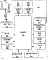
图1是示出了根据本发明的无线通信网络中无线通信设备的相关部件的方框图;FIG. 1 is a block diagram showing relevant components of a wireless communication device in a wireless communication network according to the present invention;
图2是根据本发明的图1的优选无线通信设备的更详细的图示;Figure 2 is a more detailed illustration of the preferred wireless communication device of Figure 1 in accordance with the present invention;
图3示出了本发明的背光液晶显示器的实施例;Fig. 3 shows the embodiment of backlight liquid crystal display of the present invention;
图4示出了本发明的液晶显示器和液晶显示器控制器的实施例;Fig. 4 shows the embodiment of liquid crystal display and liquid crystal display controller of the present invention;
图5示出了本发明的方法的流程图;Fig. 5 shows the flowchart of the method of the present invention;
图6示出了根据本发明的显示器屏幕的典型划分;Figure 6 shows a typical division of a display screen according to the present invention;
图7示出了实施例的LCD和LCD控制器的方框图;Figure 7 shows a block diagram of the LCD and LCD controller of an embodiment;
图8示出了针对光源和显示器扫描的定时方案;Figure 8 shows a timing scheme for light source and display scanning;
图9示出了光源和LCD之间的相关定时的实施例;Figure 9 shows an embodiment of relative timing between a light source and an LCD;
图10示出了光源和LCD之间的相关定时的可选实施例;Figure 10 shows an alternative embodiment of the relative timing between the light source and the LCD;
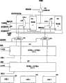
图11示出了具有可选截止区域的具体实施例;Figure 11 shows a specific embodiment with optional cut-off regions;
图12示出了栅极线驱动器的部分的实施例;Figure 12 shows an embodiment of a portion of a gate line driver;
图13(a)到(d)示出了用于扫描图11的具体实施例的流程图;Figure 13 (a) to (d) show the flow chart for scanning the specific embodiment of Figure 11;
图14示出了图13的方法的概况;以及Figure 14 shows an overview of the method of Figure 13; and
图15示出了在一帧之内针对一个色彩扫描的实施例的进一步详细描述。Figure 15 shows a further detailed description of an embodiment of scanning for one color within one frame.
具体实施方式Detailed ways
本发明涉及一种方法和设备,尤其涉及例如手持通信设备的移动站,其实现了用于减少显示器中功率切换损耗的方法。优选地,显示器是液晶显示器,并且光源包括不同色彩的发光二级管(LED)。液晶显示器可以按照每秒钟30或更高的帧频进行操作。LCD控制器在每一帧期间提供了一列脉冲,所述脉冲的数目或长度或二者兼有可以改变。脉冲的数目或单个脉冲的脉冲宽度可以用于改变象素的灰度级。优选地,光源的LED包括红、绿和蓝色。本发明设想了例如青色、品红和黄色的其它色彩方案。可以通过调整LCD控制器从而驱动每帧中不同的栅极线,从而实现本发明。尽管在实质上本发明集中在液晶显示器上,但是LCD的优选使用是在移动站中。The present invention relates to a method and apparatus, and more particularly to a mobile station such as a handheld communication device, implementing a method for reducing power switching losses in a display. Preferably, the display is a liquid crystal display and the light source comprises light emitting diodes (LEDs) of different colours. Liquid crystal displays can operate at a frame rate of 30 or more per second. The LCD controller provides a train of pulses during each frame, the number or length of the pulses or both can be varied. The number of pulses or the pulse width of a single pulse can be used to change the gray level of a pixel. Preferably, the LEDs of the light source include red, green and blue. Other color schemes such as cyan, magenta, and yellow are contemplated by the present invention. The invention can be implemented by adjusting the LCD controller to drive different gate lines in each frame. Although in essence the present invention focuses on liquid crystal displays, the preferred use of LCDs is in mobile stations.
图1是通信系统100的方框图,所述通信系统包括通过无线通信网络进行通信的移动站102。优选地,移动站102包括可视显示器112、键盘114以及可能一个或多个辅助用户接口(UI)116,其中每一个与控制器106相连。控制器106还与射频(RF)收发机108和天线110相连。1 is a block diagram of a communication system 100 that includes a
通常,控制器106表现为中央处理器(CPU),所述CPU在存储器部件(未示出)中运行操作系统软件。控制器106通常控制移动站102的整体操作,而与通信功能相关联的信号处理操作通常在RF接收机电路108中执行。控制器106设备与显示器112相接,从而显示所接收的信息、所存储的信息、用户输入等。键盘114可以是电话类型的小键盘或者完整字母数字的键盘,通常提供键盘用于输入存储在移动站102中的数据、向网络传输的信息、设置电话呼叫的电话号码、要在移动站102上执行的命令以及可能的其它或不同的用户输入。Typically, the
移动站102通过天线110将通信信号发送给无线链路上的无线网络,并从其接收通信信号。RF收发机电路108执行与基站和基站控制器(BSC)(未示出)的功能相类似的功能,包括例如调制/解调和可能的编码/解码以及加密/解密。还设想RF收发机电路108可以执行除由BSC所执行功能之外的某些功能。对于本领域的技术人员来说显而易见,使RF收发机电路108适应移动站102将意欲在其中操作的一个或多个具体网络。
移动站102包括用于容纳一个或多个可充电电池132的电池接口(IF)134。电池132为移动站102中的电路提供电功率,并且电池IF134为电池132提供机械连接和电连接。电池IF 134与调节器136相连,所述调节器调节设备的功率。当移动站102完全运作时,通常RF收发机电路108的RF发射机仅当其向网络发送时被操作(keyed)或开启,并且否则被关闭从而节省资源。类似地,通常周期地关闭RF收发机电路108的RF接收机,从而节省功率,直到在所指定的事件周期期间需要接收信号或信息(如果存在)。The
移动站102使用订户身份识别模块(SIM)140进行操作,所述SIM在SIM接口(IF)142处连接到或插入移动站102。SIM 140是传统的“智能卡”的一种类型,其中所述传统“智能卡”用于识别移动站102终端用户(或者订户)以及用于个性化设备。没有SIM 140,移动站终端不能通过无线网络进行完全通信操作。通过将SIM 140插入移动站102中,终端用户可以访问任何和全部他/她所预定的服务。通常,SIM 140包括处理器和用于存储信息的存储器。由于SIM 140与SIM IF 142相连,其通过通信线144与控制器106相连。为了识别订户,SIM 140包含一些用户参数,例如国际移动订户身份(IMSI)。使用SIM 140的优点是终端用户不需要被任何单个物理移动站所绑定。SIM 140还可以存储用于移动站的额外用户信息,包括数据手册(或者日历)信息以及最近的呼叫信息。The
移动站102可以包括单个单元,例如数据通信设备、具有数据的多功能通信设备以及语音通信能力,对于无线通信可用的个人数字助理(PDA),或者包括内部调制解调器的计算机。可选地,移动站102可以是包括多个分离部件的多模块单元,包括但不局限于计算机或者连接到无线调制解调器的其它设备。具体地,例如,在图1的移动站方框图中,RF接收机电路108和天线110可以实现为可以插入膝上型计算机的端口中的无线电调制解调器单元。在这种情况下,膝上型计算机可以包括显示器112、键盘114、一个或多个辅助UI 116、以及体现为计算机CPU的控制器106。还设想通常可以调整不能进行无线通信的计算机或者其它装置,使其能够连接到并且有效进行RF收发机电路108和例如上述之一的单个单元设备的天线110的控制。这种移动站102可以具有更具体的实现,如根据图2的移动站202的下述描述。
优选地,图2是移动站202的详细方框图。优选地,移动站202是至少具有语音和高级数据通信能力的双向通信设备,包括与其它计算机系统通信的能力。依赖于移动站202所提供的功能,可以认为其是数据消息传递设备、双向寻呼机、具有数据消息传递功能的蜂窝电话、无线因特网装置、或者数据通信设备(具有或者没有电话技术能力)。移动站202可以在其地理覆盖区内与多个混合收发机站200中的任一进行通信。Preferably, FIG. 2 is a detailed block diagram of a
移动站202将通常包括在通信子系统211中,其包括接收机、发射机以及相关联的部件,例如一个或多个(优选是嵌入或内置的)天线器件和本地振荡器(LOs),以及例如数字信号处理器(DSP)(未示出)的处理模块。通信子系统211类似于图1所示的RF收发机电路108和天线110。对于通信领域的技术人员来说显而易见,通信子系统211的具体设计依赖于移动站202要在其中进行操作的通信网络。The
网络访问与移动站202的订户或者用户相关联,并且因此移动站202要求将订户身份识别卡或者“SIM”卡262插入SIM IF 264,以便于在网络中操作。SIM 262包括根据图1所描述的特点。移动站202是电池供电的设备,所以其还包括电池IF 254,用于容纳一个或多个可充电电池256。如果不是所有电路均处于移动站202中,这种电池256为大多数提供电功率,并且电池IF 254为其提供机械连接和电连接。电池IF 254与调节器(未示出)成对,所述调节器向所有电路提供功率V+。Network access is associated with the subscriber or user of the
移动站202包括微处理器238(其是图1的控制器106的一种实现),所述微处理器控制移动站202的整体操作。通过通信子系统211执行至少包括数据和语音通信的通信功能。微处理238还与附加设备子系统进行交互,所述附加设备子系统例如显示器222、快闪存储器224、随机存取存储器(RAM)226、辅助输入/输出(I/O)子系统228、串行端口230、键盘232、扬声器234、麦克风236短距离通信子系统240、以及通常在242所指派的任何其它设备子系统。图2中所示的一些子系统执行与通信相关的功能,而其它子系统可以提供“驻留的”或者设备上的功能。值得注意的是,例如键盘232和显示器222的一些子系统,例如,可以用于与通信相关的功能,例如输入在通信网络上传递的文本消息,以及驻留设备的功能,例如计算器或者任务列表。微处理器238所使用的操作系统软件优选存储于例如快闪存储器224的永久性存储器中,可选地,其可以是只读存储器(ROM)或者类似的存储器件(未示出)。本领域的技术人员将理解,操作系统、具体的设备应用或者其部件可以临时加载到易失性存储器中,例如RAM226。The
除了其操作系统功能,优选地,微处理器238使得在移动站202上可以执行软件应用。预定的控制基本设备操作的应用集合,至少包括数据和语音通信应用,通常在其制造期间被安装到移动站202上。可以加载到移动站202上的优选应用可以是具有组织和管理关于用户的数据项的个人信息管理器(PIM)应用,例如,但并不局限于即时消息传递(IM)、电子邮件、日历事件、语音邮件、约会和任务项。当然,在移动站202和SIM 262上可用一个或多个存储器存储单元,从而便于PIM数据项和其它信息的存储。In addition to its operating system functions,
优选地,PIM应用具有通过无线网络发送和接收数据项的能力。在优选实施例中,PIM数据项通过无线网络被无缝地集成、同步和更新,因此,所存储的和/或与主计算机系统相关联的移动站用户的相应数据项相对于这些项在移动站202上产生镜像主计算机。这在主计算机系统是移动站用户的办公计算机系统的情况下是尤其有利的。还可以通过网络200、辅助I/O子系统228、串行端口230、短距离通信子系统240或者任何其它合适的子系统242将附加应用加载到移动站202中,并且由用户安装在RAM 226或者优选的非易失性存储器(未示出)中,用于由微处理器238执行。这种在应用安装方面的灵活性增加了移动站202的功能性,并且可以提供增强的设备上(on-device)功能、通信相关功能或二者。例如,安全通信应用使得能够使用移动站202执行电子商务功能和其它财务交易。Preferably, the PIM application has the capability to send and receive data items over a wireless network. In a preferred embodiment, the PIM data items are seamlessly integrated, synchronized and updated over the wireless network so that the corresponding data items of the mobile station user stored and/or associated with the host computer system are moved relative to these items A mirrored host computer is created on
在数据通信模式下,可以由通信子系统211处理例如文本消息、电子邮件消息或者网页下载的接收信号,并且将其输入到微处理器238。优选地,微处理器238将进一步处理信号,用于向显示器222、辅助I/O设备228或者二者输出,正如以下的参考图3-7所描述。例如,移动站202的用户还可以使用键盘232连同显示器222以及可能的辅助I/O设备228编辑诸如电子邮件信息的数据项。键盘232优选是完整字母数字键盘和/或电话类型的小键盘。可以通过通信子系统211在通信网络上发送这些所编辑的数据项。In data communication mode, received signals such as text messages, e-mail messages, or web page downloads may be processed by the
对于语音通信,除了所接收的信号将输出到扬声器234以及将由麦克风236产生用于传输的信号,移动站202的总体操作实质上是类似的。还可以在移动站202上实现可选的语音或者视频I/O子系统,例如语音消息记录子系统。尽管优选主要通过扬声器234完成语音或音频信号的输出,显示器222还可以用于在语音呼叫期间提供呼叫方身份的指示或者如一些示例中的其它语音呼叫相关的信息。For voice communications, the overall operation of
通常在个人数字助理(PDA)类型的通信设备中实现图2中的串行端口230,为此希望与用户的桌面计算机进行同步,尽管是可选的。串行端口230使得用户能够通过外部设备或者软件应用设置首选项,并且除了通过无线通信网络,利用向移动站202提供信息或者软件下载,扩展移动站202的能力。例如,可以通过直接并且因此可靠且可信的与提高安全设备通信的连接,使用可选的下载路径将加密密钥下载到移动站202上。
图2的短距离通信子系统240是附加的可选部件,其为移动站202和不同系统或设备之间提供通信,这不需要像类似的设备。例如,子系统240可以包括红外设备和所关联的电路及部件或者BluetoothTM通信模块,从而为类似使能的系统和设备提供通信。BluetoothTM是Bluetooth SIG公司的注册商标。The short-
根据本发明的实施例,移动站202是多任务手持无线通信设备,其配置用于发送和接收数据项,以及用于制造和接收语音通话。为了提供用户友好的环境从而控制移动站202的操作,驻留在站202(未示出)上的操作系统提供了GUI,所述GUI具有主屏幕和相对于主屏幕可操纵(navigable)的多个子屏幕。According to an embodiment of the present invention,
图3更详细地示出了液晶显示器单元222,其中将从多个LED322、324、326所形成的光源用作背光。LCD控制器316向有源矩阵的公共电极308和有源器件310提供电压。有源器件优选是薄膜晶体管。分别在衬底306和312上支持公共电极308和有源器件。优选地,LCD包括亮度增强膜或层304,从而最优化对于观众的光分布。由于优选的液晶材料是上等的扭转向列,使用了偏振膜302和314。液晶控制器316设置LCD的象素灰度级。可选的处理器318可以调整LCD控制器316与光源控制器320的同步。优选地,将LCD控制器316和处理器318集成到单个设备317中,可以将其简单地称作具有控制光源控制器320能力的LCD控制器。可以通过使用红色、绿色和蓝色LED 322、324、326来实现光源。在具体实施例中,使用四个绿色、四个红色和两个蓝色LED以提供全彩色和/或黑白显示器。LED控制器320可以排列三个色彩的顺序,或者可以同时为所有色彩的LED供电,并且同时终止提供给LED的功率。光导328可以具有倾斜阻挡(tapered block)结构,并且可以近似地具有梯形形式,从而将光更均匀地分布在LCD中。光导还可以具有不平坦区域330、332,用于散射光以避免LCD图像中的屏蔽效应。尽管示出了不平坦区域330从光导328的表面向外凸出,并且示出了不平坦区域332向光导328的表面内部凸出,只要该排列能够有效地散射来自LED 322的光,可以对不平坦区域进行不同的排列。可以研磨、浇铸、波纹、化学蚀刻等不平坦区域。优选地,为了最大化对光的利用,由反射器部分包围LED322、324、326和光导328,从而使得仅开口完全由LCD的光透射区域限定。Figure 3 shows the liquid
图4示出了用于本发明的方法的LCD控制器402和LCD 430的实施例。LED控制器可以内在地适于提供光序列,每一序列以根据已激发的LED的具体波长为中心,其后是从所有LED或者至少两个LED同时所产生的光,所述LED产生以两个不同波长为中心的光。在图4中,在与LED控制器同步的过程中,LCD控制器402根据X-Y矩阵排列中的列驱动器410(源驱动器)和行选择器412-422(栅极驱动器),针对以具体波长为中心每一个光来产生灰度级图案。对于红光图案,仅将由类驱动器410可选择的象素设置为透射状态,从而提供所期望的图案。关闭不具有光的红色分量的象素。随后对于绿光和蓝光图案,进行类似的过程。当通过给定象素透射所有红、绿和蓝色时,因为由观众所观察到地三基色的混合,该象素可以表现为白色或者类似白色。使用光源确定色彩的优点包括消除了彩色滤波器层,因此通过减少光吸收层而增强了显示器的亮度,并且由于仅需要一个象素提供全部色彩而不是分离的红、绿和蓝象素,从而提高了分辨率。在分辨率提高的同时,允许象素的尺寸增加;换句话说,使用光源而不是LCD来确定色彩,优化了衬底真实状态(estate)的使用率。FIG. 4 shows an embodiment of an LCD controller 402 and an LCD 430 for the method of the present invention. The LED controller may be inherently adapted to provide sequences of light, each sequence centered at a specific wavelength according to the LEDs that have been excited, followed by light simultaneously generated from all LEDs or from at least two LEDs that generate light in two Light centered at different wavelengths. In FIG. 4, in the process of synchronizing with the LED controller, the LCD controller 402, according to the column driver 410 (source driver) and the row selectors 412-422 (gate driver) in the X-Y matrix arrangement, targets at a specific wavelength of Center each light to produce grayscale patterns. For the red pattern, only the pixels selectable by the class driver 410 are set to the transmissive state, thereby providing the desired pattern. Pixels that do not have the red component of light are turned off. A similar process followed for the green and blue patterns. When all red, green and blue are transmitted through a given pixel, that pixel may appear white or nearly white because of the mixing of the primary colors as observed by the viewer. Advantages of using a light source to determine color include the elimination of color filter layers, thus enhancing the brightness of the display by reducing the number of light-absorbing layers, and since only one pixel is required to provide the full color rather than separate red, green, and blue pixels, Improved resolution. This allows the pixel size to increase at the same time as the resolution; in other words, using the light source instead of the LCD to determine color optimizes the utilization of the substrate real estate.
图5中概括地示出了本发明的方法。尽管本实施例针对将LCD屏幕划分为单色和彩色区域,但是设想了其它方案,例如高比特率彩色、低比特率彩色、单色等。处理器将某些线指定为彩色502或者单色504。认为其余线处于截止状态。如果显示器屏幕在显示模式508下是工作的,则在扫描任何单色线之前扫描所有彩色线。首先扫描彩色线的原因是因为其具有不同于单色线的计时(clocking)方案。在其它实施例中,可以在扫描彩色线之前扫描单色线。如果单色和/或彩色线要进行改变514,通过重复步骤501-506来确定新配置。在彩色区域中的扫描涉及:在第二或连续扫掠(sweep)彩色区域中的任一线之前先对扫描区域中的每一线进行第一扫掠。The method of the present invention is schematically shown in FIG. 5 . Although the present embodiment is directed to dividing the LCD screen into monochrome and color regions, other schemes are contemplated, such as high bit rate color, low bit rate color, monochrome, etc. The processor designates certain lines as color 502 or monochrome 504 . The remaining threads are considered to be in cut-off state. If the display screen is active in display mode 508, all colored lines are scanned before any monochromatic lines are scanned. The reason color lines are scanned first is because they have a different clocking scheme than monochrome lines. In other embodiments, monochromatic lines may be scanned before colored lines. If monochromatic and/or colored lines are to be changed 514, a new configuration is determined by repeating steps 501-506. Scanning in a colored area involves taking a first sweep of each line in the scanned area before a second or successive sweep of any line in the colored area.
图6示出了本发明中通常显示屏幕的实施例。显示器602、612的顶部和底部区域都为截止(off)。截止区域的着色依赖于无偏的液晶材料和任意偏振膜的方向。在显示器屏幕的典型划分中,彩色区域604、单色区域606、其它彩色区域608以及其它单色区域610位于顶部和底部截止区域602、612之间。很清楚可以具有许多其它排列;但是,在本发明中,显示器屏幕基本划分为水平带,其是三种模式之一:彩色、单色或者截止。例如,显示器屏幕可以划分为单色区域和截止区域、单色区域和彩色区域、或者彩色区域和截止区域。Fig. 6 shows an example of a typical display screen in the present invention. Both the top and bottom regions of the displays 602, 612 are off. The coloration of the cut-off region depends on the unbiased liquid crystal material and the orientation of any polarizing film. In a typical division of a display screen, the color region 604 , the monochrome region 606 , the other color region 608 , and the other monochrome region 610 are located between the top and bottom cutoff regions 602 , 612 . Clearly many other arrangements are possible; however, in the present invention, the display screen is essentially divided into horizontal strips, which are one of three modes: color, monochrome or cutoff. For example, a display screen may be divided into a monochrome area and a cutoff area, a monochrome area and a color area, or a color area and a cutoff area.
图7示出了LCD控制器器件和LCD的实施例的方框图。通过源驱动器704为象素提供灰度级。存储器712用于提供图像数据。存储器可以是易失性的,例如随机存取存储器,或者非易失性的,例如只读存储器。使用图像数据来访问一比特图案,用于提供灰度级或者通过查询表来切换象素。查询表A 708提供多比特图案,其表示了灰度级值,或与其相关。优选地,图案的比特至少共计为6,并且可以是8、10、12或者总共16。查询表B 710提供了单个比特或者比特序列,所述比特表示单色区域中的象素或显示器屏幕上的线的导通或截止状态。可选地,可以提供截止状态值,其中源极驱动器将不偏离由开关(即,多路复用器)706所选择的液晶显示器象素。栅极线驱动器工作,从而独立扫掠可扫描区域的两种类型的每一种。即,将访问彩色区域扫描序列存储器件724,并且在为扫描而访问单色序列存储器件726之前或之后,使用其扫描所指定的显示器屏幕702的部分。扫描单色扫描序列存储器件726的频率不同于针对彩色存储器件724的频率。开关722向栅极驱动器720提供了正确的序列,并且,可选地,在剩余的时间期间,使栅极针对OFF区域无效。Figure 7 shows a block diagram of an embodiment of an LCD controller device and LCD. Gray scale is provided to the pixels by the source driver 704 . The memory 712 is used to provide image data. Memory can be volatile, such as random access memory, or non-volatile, such as read-only memory. Use the image data to access a one-bit pattern for providing grayscale or to switch pixels through a look-up table. Look-up table A 708 provides a multi-bit pattern that represents, or is related to, grayscale values. Preferably, the bits of the pattern add up to at least 6, and may be 8, 10, 12 or 16 in total. Look-up table B 710 provides a single bit or sequence of bits that represent the on or off state of a pixel in a monochrome region or a line on a display screen. Alternatively, an off-state value can be provided where the source driver will not deviate from the LCD pixel selected by switch (ie, multiplexer) 706 . The gate line drivers operate to independently scan each of the two types of scannable areas. That is, the color area scan sequence storage device 724 will be accessed and used to scan the designated portion of the display screen 702 before or after the monochrome sequence storage device 726 is accessed for scanning. The frequency at which the monochrome scan sequence storage device 726 is scanned is different than the frequency for the color storage device 724 . Switch 722 provides the correct sequence to gate driver 720 and, optionally, deactivates the gate for the OFF region during the remainder of the time.
图8示出了仅彩色模式,其中整个显示器屏幕是彩色的,或者显示器屏幕的非彩色部分处于截止状态。在操作中,通过在扫描期间写入象素的脉冲而得到象素灰度级。在全彩色模式下,针对三个色彩将每一个彩色帧802划分为三部分(或场)804、806、808。通过光的具体色彩所照亮的每一个象素从脉冲图案得到灰度级值,所述脉冲图案进入向象素提供电荷的薄膜晶体管的源极。脉冲图案(即,彩色扫描)包括针对每一个象素的多个较高和/或较低的脉冲。在扫描包括彩色象素的彩色区域期间,对每一个彩色象素应用一个脉冲。在彩色区域扫描(或扫掠)832期间,真正的扫描占据了针对给定色彩的时间分配830的大部分。在一帧期间,彩色象素的连续扫描建立了灰度级值。在扫描周期内的时间分配的较小部分是空闲时间834。在扫描周期的大部分期间,光源关闭814。在可选的实施例中,对于大部分或者全部扫描周期,光源可以保持开启,和/或真实扫描可以针对给定色彩占据时间分配的不同部分。当针对象素的行或列的最终的灰度级值相当合适地建立时,开启光源(例如,发光二极管)812。在一些实施例中,在光源开启期间,显示器的公共电极从第一偏压电平822反转为第二偏压电平824,从而阻止电荷在液晶中积累,所述积累将降低性能并且破坏显示器。针对每一帧的每一个色彩出现公共电极电压的反转。因此,针对红色、绿色和蓝色象素LCD,公共电极电压反转三次。本发明设想了其它反转模式,例如行反转和象素反转。在行反转中,可选地,可以通过源极驱动器从极性的第一集合为给定行提供电压,并且然后从与第一集合相反的极性的第二集合提供电压;即,可以应用电压的非反转对,并且可以以后应用电压的非反转对。在象素反转中,可以为每一行提供具有相反极性的电压集合的任意列。Figure 8 shows a color-only mode, where the entire display screen is in color, or the achromatic portion of the display screen is turned off. In operation, pixel gray levels are obtained by writing pulses to the pixel during scanning. In full color mode, each
从在单色区域中切换的减少可以得到本发明的节约功率的优点。图9和图10示出了针对具有单色和彩色区域的显示器的单个帧的两个实施例。在图9中,每一个象素被激发一次时出现单色扫描916。在单色扫描期间,使用一个时钟脉冲为单色象素设置开启或关闭值,得到较少的切换功率消耗。则,从栅极线驱动器由多脉冲得到灰度级值,其中在与场中的单个色彩相对应的多扫描期间,源驱动器加载新数据。在扫描时间的大部分期间,没有照明906。在扫描的末端,开启所指派的彩色的光源904,同时栅极驱动器变得空闲912。图10示出了可选实施例,其中单色和彩色扫描1016、1014与图9所示相同,但是对于具有短LED OFF时间1006的更长的时间周期1004、1008,光源以更低的功率工作。The power saving advantages of the present invention can be derived from the reduction in switching in monochromatic regions. Figures 9 and 10 show two embodiments of a single frame for a display with monochrome and color regions. In FIG. 9, monochrome scanning 916 occurs when each pixel is fired once. During monochrome scanning, one clock pulse is used to set the on or off value for monochrome pixels, resulting in less switching power consumption. Gray scale values are then derived from multiple pulses from the gate line drivers, where the source drivers are loaded with new data during the multiple scans corresponding to a single color in the field. During most of the scan time, there is no illumination 906. At the end of the scan, the light source of the assigned color is turned on 904 while the gate driver becomes idle 912 . Figure 10 shows an alternative embodiment where the monochrome and
图11示出了本发明的更具体的实施例,其中将显示器屏幕分别划分为几个区域,其中由源极驱动器1102和栅极驱动器1104激发象素。显示器屏幕的顶部和底部是截止区域1108、1116。显示器屏幕的中心是在两个彩色区域1110、1114之间的单色区域1112。使用如图12所示的两个输出移位寄存器(例如,串行输入/并行输出移位寄存器)A、B扫描两个彩色区域。移位寄存器A 1210和移位寄存器B 1208分别包含用于区域A和B的栅极移位寄存器的初始化值。优选地,其包含其各自区域的起始线(starting line)数目的one-hot编码。(正如本发明的实施例中所使用,one-hot编码指单个现用比特,其通过移位寄存器移位,从而使得在某一时间的象素仅一行从源驱动器写入。)加载第一移位寄存器A 1210,并且将其用于扫描一次第一彩色区域,然后加载移位寄存器B 1208,并且将其用于扫描一次第二彩色区域。交替移位寄存器,直到完成该帧中的全部扫描数目。在彩色区域扫描时间期间,时钟速率COLOUR LINE CLOCK相当高。例如,可以使用10MHz的时钟。在扫描彩色区域之后,使用较低的时钟MONO LINE CLOCK扫描单色区域,从而将二进制值输入到象素以引起象素的导通或截止。可以使用开关1228,通过图7中的REGION SELECT信号,向根据区域的存储器件1218、1226传输COLOUR LINE CLOCK或者MONOLINE CLOCK。存储器件1218、1226可以是锁存器,其将数据锁定在时钟、D类型触发器等的上升沿或下降沿上。使用计数器1202-1206掌握每一个区域中线的数目。在可选的实施例中,在扫描任何其它彩色区域之前,多次扫描每一个彩色区域。在另一个实施例中,在扫描彩色区域之前扫描单色区域。FIG. 11 shows a more specific embodiment of the present invention, in which the display screen is divided into several areas respectively, where the pixels are driven by the
图14示出了与图12的显示器扫描系统相对应的本发明的方法的实施例的概况。在通常的方法中,进行初始化1404(例如,初始化寄存器),并且通过在一帧期间的从1406-1410的连续扫描,三个彩色场进行循环。单色区域可以在所有、部分或者单个彩色场期间进行更新。FIG. 14 shows an overview of an embodiment of the method of the present invention corresponding to the display scanning system of FIG. 12 . In a typical approach, initialization 1404 occurs (eg, registers are initialized), and the three color fields cycle through successive scans from 1406-1410 during a frame. Monochrome regions can be updated during all, part, or a single color field.
图13示出了图14的方法的更详细的实施例。开始,通过开关1228,将栅极时钟设置等于COLOUR LINE CLOCK。解除声明(deassert)图12的LOAD SOURCE PATTERN 1302,从而使得OUTPUT SHIFT REGISTER能够将其数据移位。加载计数器1202-1206,加载每个色彩的扫描数目,并且加载彩色和单色存储器件1208-12101304。关闭光源1306。加载对彩色区域B的计数12041308。针对计数器的每一个计数,只要计数器没有超时1310:栅极时钟以COLOUR LINE CLOCK频率进行切换1312,初始化栅极移位寄存器1314,从而通过使用开关A和B(图12)以及坚持LOAD SOURCEPATTERN(图12),在彩色区域B 1114的起始处开始扫描,并且一连串栅极时钟引起彩色区域B的每一行1114接收新的源图案1507,其用于加载显示器屏幕1316的彩色区域B 1114中的唯一线(行)。然后,加载彩色区域A的计数器,并且除了区域A 1110,针对计数器的每一个计数重复类似处理,只要计数器不超时1320、1322、1324、1326。在已充分扫描彩色区域从而建立其灰度级值之后,开启光源1328、1330。在已完全扫描彩色区域之后(即,脉冲序列平面是零)1332、1334,公共电极极性反转1346。如果确定要刷新单色区域1336,则为计数器加载单色区域中的线数目M 1338,并且如果计数不是零,则以降低的时钟频率1342扫描单色区域一次1344,所述降低的时钟频率由线时钟的划分而确定,而线时钟由每场的扫描数目划分,从而产生MONO LINE CLOCK。可以通过其它方式建立所降低的时钟频率,并且所述时钟频率可以占用周期的空闲时间。FIG. 13 shows a more detailed embodiment of the method of FIG. 14 . Initially, the gate clock is set equal to COLOUR LINE CLOCK via switch 1228. The
可以用多种其它方式输入图13的方法。在一个实施例中,在正常模式下,可以将计数加载到串行输入/并行输出移位寄存器A、B,然后将模式切换到部分彩色。参考完第一行之后,使栅极驱动器的输出无效。然后,当恢复单色启动时,使栅极驱动器输出有效。栅极时钟减速。驱动彩色区域B的每一行,直到到达彩色区域B的末端。输出移位寄存器复位为SIPO A。驱动彩色区域A的每一行,直到到达彩色区域A的末端。然后,输出移位寄存器复位为SIPO B,除非已经针对该帧执行了预定的扫描数目,所述扫描数目用于得到灰度级。如果达到了预定的扫描数目,则使栅极时钟无效,开启光源,并且公共电极反转。确定是否恢复正常模式。如果不,则保持部分彩色模式,并且通过降低栅极时钟再一次开始处理。否则,假设是正常模式,直到第一行准备好数据传输,在所述正常模式下,使用快速栅极时钟控制显示器的象素栅极,并且栅极驱动器的输出无效。通过示意性的示例,如果M表示单色区域扫描,并且BA表示彩色区域B和A的扫描,则可以将处理描述为:M BA BA BA BA BA BA BA BA BA BA BABA反转等待,其中,在彩色区域BA扫描的最后一个或者最后几个、反转周期以及等待周期期间导通光。The method of FIG. 13 may be imported in a variety of other ways. In one embodiment, in normal mode, the counts can be loaded into the serial-in/parallel-out shift registers A, B and then the mode switched to partial color. After referencing the first row, deassert the output of the gate driver. Then, when monochrome startup is restored, the gate driver output is asserted. The gate clock is decelerated. Drive each row of colored region B until the end of colored region B is reached. The output shift register is reset to SIPO A. Each row of colored area A is driven until the end of colored area A is reached. Then, the output shift register is reset to SIPO B, unless a predetermined number of scans have been performed for the frame, which is used to obtain gray levels. If the predetermined number of scans is reached, the gate clock is deactivated, the light source is turned on, and the common electrode is inverted. Determine whether to return to normal mode. If not, the partial color mode is maintained and processing is started again by lowering the gate clock. Otherwise, normal mode is assumed, in which the pixel gates of the display are controlled using a fast gate clock and the output of the gate driver is inactive until the first row is ready for data transfer. By way of a schematic example, if M denotes a monochrome area scan, and BA denotes a scan of color areas B and A, then the process can be described as: M BA BA BA BA BA BA BA BA BA BABA reverse wait, where, The light is turned on during the last or last few scans of the color area BA, the inversion period, and the waiting period.
图15示出了针对场扫描的更详细的实施例。栅极线驱动器移位一次1504。不声明加载模式1506。加载新的源模式1507。驱动显示矩阵上的源极线1508。行计数器减11510。只要不终止计数器(例如,在倒计数模式下,行计数保持大于零)1512,在步骤1504重新开始扫描。Figure 15 shows a more detailed embodiment for field scanning. The gate line driver is shifted 1504 once. Load mode 1506 is not declared. A new source schema is loaded 1507 . The source lines 1508 on the display matrix are driven. The row counter is decremented by 11510. As long as the counter is not terminated (eg, in countdown mode, the row count remains greater than zero) 1512, scanning is resumed at step 1504.
本应用的上述实施例仅用于作为示例。在不偏离本申请范围的前提下,本领域的技术人员可以对具体实施例进行变化、修改和变体。在所引用的权利要求中所描述的本发明的目的是覆盖和包含本技术的所有合适修改。The above-described embodiments of the application are intended to be examples only. Variations, modifications and variations to the specific embodiments may be effected by those skilled in the art without departing from the scope of the present application. It is the intention of the invention described in the appended claims to cover and embrace all suitable modifications of the technology.
Claims (23)
Applications Claiming Priority (2)
| Application Number | Priority Date | Filing Date | Title |
|---|---|---|---|
| EP04102468.8AEP1603108B1 (en) | 2004-06-02 | 2004-06-02 | Mixed Monochrome and Colour Display Driving Technique |
| EP04102468.8 | 2004-06-02 |
Publications (2)
| Publication Number | Publication Date |
|---|---|
| CN1705008A CN1705008A (en) | 2005-12-07 |
| CN1705008Btrue CN1705008B (en) | 2010-04-28 |
Family
ID=34929162
Family Applications (1)
| Application Number | Title | Priority Date | Filing Date |
|---|---|---|---|
| CN 200510075422Expired - LifetimeCN1705008B (en) | 2004-06-02 | 2005-06-01 | Method for realizing multi-scan mode on display screen and wireless communication device |
Country Status (4)
| Country | Link |
|---|---|
| EP (1) | EP1603108B1 (en) |
| CN (1) | CN1705008B (en) |
| CA (1) | CA2508183C (en) |
| SG (1) | SG117594A1 (en) |
Families Citing this family (12)
| Publication number | Priority date | Publication date | Assignee | Title |
|---|---|---|---|---|
| GB0918147D0 (en)* | 2009-10-16 | 2009-12-02 | Liquavista Bv | Display device and display apparatus |
| TWI425488B (en)* | 2009-11-03 | 2014-02-01 | Nuvoton Technology Corp | Driver of field sequential display and driving mehtod thereof |
| CN102346996B (en)* | 2010-08-04 | 2013-12-25 | 深圳莱宝高科技股份有限公司 | Display apparatus and driving circuit thereof |
| SG11201502619UA (en)* | 2012-10-05 | 2015-05-28 | Tactual Labs Co | Hybrid systems and methods for low-latency user input processing and feedback |
| US10482822B2 (en) | 2016-09-09 | 2019-11-19 | Apple Inc. | Displays with multiple scanning modes |
| US10109240B2 (en) | 2016-09-09 | 2018-10-23 | Apple Inc. | Displays with multiple scanning modes |
| CN106652972B (en) | 2017-01-03 | 2020-06-05 | 京东方科技集团股份有限公司 | Processing circuit of display screen, display method and display device |
| CN106782268B (en) | 2017-01-04 | 2020-07-24 | 京东方科技集团股份有限公司 | Display system and driving method for display panel |
| CN107145192B (en) | 2017-04-27 | 2021-01-15 | Oppo广东移动通信有限公司 | Electronic device |
| JP7252786B2 (en)* | 2019-02-28 | 2023-04-05 | キヤノン株式会社 | Communication device, communication method, and program |
| CN112447145B (en)* | 2019-08-29 | 2022-06-24 | 北京小米移动软件有限公司 | Display panel, display mode switching method and device, and electronic equipment |
| CN114582252B (en)* | 2022-02-28 | 2023-11-24 | 深圳市思坦科技有限公司 | Display module, display panel and display |
Citations (3)
| Publication number | Priority date | Publication date | Assignee | Title |
|---|---|---|---|---|
| EP0852371A1 (en)* | 1995-09-20 | 1998-07-08 | Hitachi, Ltd. | Image display device |
| CN1322339A (en)* | 1999-09-27 | 2001-11-14 | 时至准钟表股份有限公司 | Method for driving color liquid crystal display panel and method for control of display of time piece |
| CN1409290A (en)* | 2001-10-01 | 2003-04-09 | 株式会社半导体能源研究所 | Display device and electronic equipment using said display device |
Family Cites Families (8)
| Publication number | Priority date | Publication date | Assignee | Title |
|---|---|---|---|---|
| JPH07152340A (en)* | 1993-11-30 | 1995-06-16 | Rohm Co Ltd | Display device |
| US6677936B2 (en)* | 1996-10-31 | 2004-01-13 | Kopin Corporation | Color display system for a camera |
| US20010040538A1 (en)* | 1999-05-13 | 2001-11-15 | William A. Quanrud | Display system with multiplexed pixels |
| WO2001069584A1 (en)* | 2000-03-14 | 2001-09-20 | Mitsubishi Denki Kabushiki Kaisha | Image display and image displaying method |
| WO2001091098A1 (en)* | 2000-05-24 | 2001-11-29 | Hitachi, Ltd. | Color/black-and-white switchable portable terminal and display device |
| WO2002026905A2 (en)* | 2000-09-26 | 2002-04-04 | Matsushita Electric Industrial Co., Ltd. | Display unit and drive system thereof and an information display unit |
| GB2378343B (en)* | 2001-08-03 | 2004-05-19 | Sendo Int Ltd | Image refresh in a display |
| CN1295655C (en)* | 2001-11-24 | 2007-01-17 | Tdv技术公司 | Generation of stereo image sequence from 2D image sequence |
- 2004
- 2004-06-02EPEP04102468.8Apatent/EP1603108B1/ennot_activeExpired - Lifetime
- 2005
- 2005-05-20SGSG200503181Apatent/SG117594A1/enunknown
- 2005-05-24CACA2508183Apatent/CA2508183C/ennot_activeExpired - Lifetime
- 2005-06-01CNCN 200510075422patent/CN1705008B/ennot_activeExpired - Lifetime
Patent Citations (3)
| Publication number | Priority date | Publication date | Assignee | Title |
|---|---|---|---|---|
| EP0852371A1 (en)* | 1995-09-20 | 1998-07-08 | Hitachi, Ltd. | Image display device |
| CN1322339A (en)* | 1999-09-27 | 2001-11-14 | 时至准钟表股份有限公司 | Method for driving color liquid crystal display panel and method for control of display of time piece |
| CN1409290A (en)* | 2001-10-01 | 2003-04-09 | 株式会社半导体能源研究所 | Display device and electronic equipment using said display device |
Also Published As
| Publication number | Publication date |
|---|---|
| EP1603108B1 (en) | 2017-03-22 |
| EP1603108A1 (en) | 2005-12-07 |
| CN1705008A (en) | 2005-12-07 |
| CA2508183A1 (en) | 2005-12-02 |
| CA2508183C (en) | 2010-11-23 |
| SG117594A1 (en) | 2005-12-29 |
Similar Documents
| Publication | Publication Date | Title |
|---|---|---|
| US8134306B2 (en) | Visual notification methods for candy-bar type cellphones | |
| US7714832B2 (en) | Mixed monochrome and colour display driving technique | |
| US7239742B2 (en) | Display device and control system thereof | |
| CN1705008B (en) | Method for realizing multi-scan mode on display screen and wireless communication device | |
| CN100407257C (en) | frame rate controller | |
| CN101635132B (en) | Display device, display method, and electronic device | |
| US8421827B2 (en) | Method for maintaining the white colour point in a field-sequential LCD over time | |
| JP2021096309A (en) | Display controller, display device, control program for display controller, and control method | |
| US10783843B2 (en) | Display panel, display apparatus and driving method thereof | |
| WO2011123237A1 (en) | Reduced-power communications within an electronic display | |
| US8564529B2 (en) | Method for driving liquid crystal display device | |
| US8170626B2 (en) | Portable electronic device and display control method employed in the same | |
| KR20050060033A (en) | Image or video display device and method of controlling a refresh rate of a display | |
| EP1178650A2 (en) | Portable information terminal apparatus | |
| WO2012050675A1 (en) | Low power inversion scheme with minimized number of output transitions | |
| CN111767017A (en) | Display panel and display method thereof | |
| HK1084767A (en) | Mixed monochrome and colour display driving technique | |
| CA2518006C (en) | Visual notification methods for candy-bar type cellphones | |
| HK1084767B (en) | Mixed monochrome and colour display driving technique | |
| CN100414597C (en) | Double-mode display device of mobile communication terminal and its display method | |
| CA2519967C (en) | Method for maintaining the white colour point in a field-sequential lcd over time | |
| HK1088978A (en) | Method for maintaining the white colour point over time in a field-sequential colour lcd | |
| HK1088977A (en) | Visual notification methods for mobilephones | |
| Nguyen et al. | Improved gray‐scale monochrome and color AMEL displays using analog pixel | |
| HK1168909A (en) | Low power inversion scheme with minimized number of output transitions |
Legal Events
| Date | Code | Title | Description |
|---|---|---|---|
| C06 | Publication | ||
| PB01 | Publication | ||
| C10 | Entry into substantive examination | ||
| SE01 | Entry into force of request for substantive examination | ||
| C14 | Grant of patent or utility model | ||
| GR01 | Patent grant | ||
| CP03 | Change of name, title or address | ||
| CP03 | Change of name, title or address | Address after:Voight, Ontario, Canada Patentee after:BlackBerry Ltd. Country or region after:Canada Address before:Voight, Ontario, Canada Patentee before:RESEARCH IN MOTION Ltd. Country or region before:Canada | |
| TR01 | Transfer of patent right | ||
| TR01 | Transfer of patent right | Effective date of registration:20240528 Address after:Ai Erlandubailin Patentee after:Maliki Innovation Co.,Ltd. Country or region after:Ireland Address before:Voight, Ontario, Canada Patentee before:BlackBerry Ltd. Country or region before:Canada | |
| CX01 | Expiry of patent term | ||
| CX01 | Expiry of patent term | Granted publication date:20100428 |