CN1702328A - Vortex compressor - Google Patents
Vortex compressorDownload PDFInfo
- Publication number
- CN1702328A CN1702328ACNA2005100629936ACN200510062993ACN1702328ACN 1702328 ACN1702328 ACN 1702328ACN A2005100629936 ACNA2005100629936 ACN A2005100629936ACN 200510062993 ACN200510062993 ACN 200510062993ACN 1702328 ACN1702328 ACN 1702328A
- Authority
- CN
- China
- Prior art keywords
- safety valve
- chamber
- valve
- flow path
- scroll
- Prior art date
- Legal status (The legal status is an assumption and is not a legal conclusion. Google has not performed a legal analysis and makes no representation as to the accuracy of the status listed.)
- Granted
Links
Images


Classifications
- F—MECHANICAL ENGINEERING; LIGHTING; HEATING; WEAPONS; BLASTING
- F04—POSITIVE - DISPLACEMENT MACHINES FOR LIQUIDS; PUMPS FOR LIQUIDS OR ELASTIC FLUIDS
- F04C—ROTARY-PISTON, OR OSCILLATING-PISTON, POSITIVE-DISPLACEMENT MACHINES FOR LIQUIDS; ROTARY-PISTON, OR OSCILLATING-PISTON, POSITIVE-DISPLACEMENT PUMPS
- F04C29/00—Component parts, details or accessories of pumps or pumping installations, not provided for in groups F04C18/00 - F04C28/00
- F04C29/12—Arrangements for admission or discharge of the working fluid, e.g. constructional features of the inlet or outlet
- F04C29/124—Arrangements for admission or discharge of the working fluid, e.g. constructional features of the inlet or outlet with inlet and outlet valves specially adapted for rotary or oscillating piston pumps
- F—MECHANICAL ENGINEERING; LIGHTING; HEATING; WEAPONS; BLASTING
- F04—POSITIVE - DISPLACEMENT MACHINES FOR LIQUIDS; PUMPS FOR LIQUIDS OR ELASTIC FLUIDS
- F04C—ROTARY-PISTON, OR OSCILLATING-PISTON, POSITIVE-DISPLACEMENT MACHINES FOR LIQUIDS; ROTARY-PISTON, OR OSCILLATING-PISTON, POSITIVE-DISPLACEMENT PUMPS
- F04C18/00—Rotary-piston pumps specially adapted for elastic fluids
- F04C18/02—Rotary-piston pumps specially adapted for elastic fluids of arcuate-engagement type, i.e. with circular translatory movement of co-operating members, each member having the same number of teeth or tooth-equivalents
- F04C18/0207—Rotary-piston pumps specially adapted for elastic fluids of arcuate-engagement type, i.e. with circular translatory movement of co-operating members, each member having the same number of teeth or tooth-equivalents both members having co-operating elements in spiral form
- F04C18/0215—Rotary-piston pumps specially adapted for elastic fluids of arcuate-engagement type, i.e. with circular translatory movement of co-operating members, each member having the same number of teeth or tooth-equivalents both members having co-operating elements in spiral form where only one member is moving
- F—MECHANICAL ENGINEERING; LIGHTING; HEATING; WEAPONS; BLASTING
- F04—POSITIVE - DISPLACEMENT MACHINES FOR LIQUIDS; PUMPS FOR LIQUIDS OR ELASTIC FLUIDS
- F04C—ROTARY-PISTON, OR OSCILLATING-PISTON, POSITIVE-DISPLACEMENT MACHINES FOR LIQUIDS; ROTARY-PISTON, OR OSCILLATING-PISTON, POSITIVE-DISPLACEMENT PUMPS
- F04C29/00—Component parts, details or accessories of pumps or pumping installations, not provided for in groups F04C18/00 - F04C28/00
- F04C29/0021—Systems for the equilibration of forces acting on the pump
- F—MECHANICAL ENGINEERING; LIGHTING; HEATING; WEAPONS; BLASTING
- F16—ENGINEERING ELEMENTS AND UNITS; GENERAL MEASURES FOR PRODUCING AND MAINTAINING EFFECTIVE FUNCTIONING OF MACHINES OR INSTALLATIONS; THERMAL INSULATION IN GENERAL
- F16F—SPRINGS; SHOCK-ABSORBERS; MEANS FOR DAMPING VIBRATION
- F16F1/00—Springs
- F16F1/02—Springs made of steel or other material having low internal friction; Wound, torsion, leaf, cup, ring or the like springs, the material of the spring not being relevant
- F16F1/04—Wound springs
- F—MECHANICAL ENGINEERING; LIGHTING; HEATING; WEAPONS; BLASTING
- F04—POSITIVE - DISPLACEMENT MACHINES FOR LIQUIDS; PUMPS FOR LIQUIDS OR ELASTIC FLUIDS
- F04C—ROTARY-PISTON, OR OSCILLATING-PISTON, POSITIVE-DISPLACEMENT MACHINES FOR LIQUIDS; ROTARY-PISTON, OR OSCILLATING-PISTON, POSITIVE-DISPLACEMENT PUMPS
- F04C2210/00—Fluid
- F04C2210/26—Refrigerants with particular properties, e.g. HFC-134a
- F—MECHANICAL ENGINEERING; LIGHTING; HEATING; WEAPONS; BLASTING
- F04—POSITIVE - DISPLACEMENT MACHINES FOR LIQUIDS; PUMPS FOR LIQUIDS OR ELASTIC FLUIDS
- F04C—ROTARY-PISTON, OR OSCILLATING-PISTON, POSITIVE-DISPLACEMENT MACHINES FOR LIQUIDS; ROTARY-PISTON, OR OSCILLATING-PISTON, POSITIVE-DISPLACEMENT PUMPS
- F04C2230/00—Manufacture
- F04C2230/20—Manufacture essentially without removing material
- F04C2230/22—Manufacture essentially without removing material by sintering
- Y—GENERAL TAGGING OF NEW TECHNOLOGICAL DEVELOPMENTS; GENERAL TAGGING OF CROSS-SECTIONAL TECHNOLOGIES SPANNING OVER SEVERAL SECTIONS OF THE IPC; TECHNICAL SUBJECTS COVERED BY FORMER USPC CROSS-REFERENCE ART COLLECTIONS [XRACs] AND DIGESTS
- Y10—TECHNICAL SUBJECTS COVERED BY FORMER USPC
- Y10S—TECHNICAL SUBJECTS COVERED BY FORMER USPC CROSS-REFERENCE ART COLLECTIONS [XRACs] AND DIGESTS
- Y10S415/00—Rotary kinetic fluid motors or pumps
- Y—GENERAL TAGGING OF NEW TECHNOLOGICAL DEVELOPMENTS; GENERAL TAGGING OF CROSS-SECTIONAL TECHNOLOGIES SPANNING OVER SEVERAL SECTIONS OF THE IPC; TECHNICAL SUBJECTS COVERED BY FORMER USPC CROSS-REFERENCE ART COLLECTIONS [XRACs] AND DIGESTS
- Y10—TECHNICAL SUBJECTS COVERED BY FORMER USPC
- Y10S—TECHNICAL SUBJECTS COVERED BY FORMER USPC CROSS-REFERENCE ART COLLECTIONS [XRACs] AND DIGESTS
- Y10S417/00—Pumps
Landscapes
- Engineering & Computer Science (AREA)
- General Engineering & Computer Science (AREA)
- Mechanical Engineering (AREA)
- Rotary Pumps (AREA)
- Applications Or Details Of Rotary Compressors (AREA)
Abstract
Translated fromChinese
Description
Translated fromChinese技术领域technical field
本发明涉及一种涡旋压缩机,特别涉及一种具备在过压缩或液体压缩时从工作室释放出工作流体的安全阀装置的涡旋压缩机。The present invention relates to a scroll compressor, in particular to a scroll compressor provided with a safety valve device for releasing working fluid from a working chamber during overcompression or liquid compression.
背景技术Background technique
对用于室内空调机等的涡旋压缩机来说,由于在大范围的运转条件下使用,不能避免在气体的过压缩或者冷媒或冷冻机油的液体压缩下运转。因此,希望得到能够忍受以上条件的结构的涡旋压缩机。Scroll compressors used in indoor air conditioners and the like are used under a wide range of operating conditions, and cannot avoid operation under overcompression of gas or liquid compression of refrigerant or refrigerating machine oil. Therefore, a scroll compressor having a structure capable of enduring the above conditions is desired.
作为具有防止过压缩以及液体压缩的结构的涡旋压缩机,有特开2002-221171号公报中(专利文献1)所公布的方案。从图11至图13所示的该涡旋压缩机来对其机构进行说明。As a scroll compressor having a structure for preventing overcompression and liquid compression, there is one disclosed in JP-A-2002-221171 (Patent Document 1). The mechanism of the scroll compressor shown in FIGS. 11 to 13 will be described.
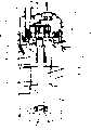
如图11所示,在具有吸入口21a和排出口21b的密闭容器21内形成有喷出压室21c。在该喷出压室21c内收放有电动机22和压缩机构部23。压缩机构部23采用使具有涡旋状气体通路的固定涡盘24、与配置成面对该固定涡盘24可以移动的具有涡旋状卷边25a的旋转涡盘25咬合而具有压缩室28的结构。旋转涡盘25与阻止旋转涡盘25的自转的同时使之公转的欧氏环26连结,同时,也与由电动机22驱动旋转的曲轴27的偏心部27a相连结。As shown in FIG. 11 , a
利用电动机22的驱动,使旋转涡盘25旋转的同时,从吸入口21 a吸入冷媒,导向由固定涡盘24和旋转涡盘25构成的压缩室28依次压缩,从固定涡盘24的喷出口24a把被压缩的冷媒排出到喷出压室21c。然后,从密闭容器21的排出口21b把被排出到喷出压室21c的冷媒排出。在该涡旋压缩机中,固定涡盘24上部的底板24b上设有连接压缩室28和喷出压室21c的安全阀装置29。Driven by the
如图12以及图13所示,该安全阀装置29形成使得释放孔29a、阀座29b、安全阀室29c、套筒压入部29d连续起来形成,并且使它们的中心线同心。再有,安全阀装置29在阀座29b与安全阀29e接触,在安全阀29e的上面与被固定在套筒29g的弹簧固定部29h上的弹簧29f接触,将套筒29g压入套筒压入部29d中。这样,安全阀29e就始终被压在阀座29b上。另外,在套筒29g上开口有排出被过压缩的气体或液体的压力逃逸孔29i。As shown in FIGS. 12 and 13 , the
该安全阀装置29在压缩行程途中,在压缩室28内的压力成为喷出压力以上的过压缩时、或在根据运转时的温度条件等从吸入口吸入液体冷媒的液体压缩时等,如图13所示,弹簧29f被压缩,安全阀29e打开。安全阀29e打开是在过压缩到超过设定压力(喷出压力+安全阀29e的重量+弹簧29f的弹性推压力)的场合。通过安全阀29e的打开,上升到喷出压室21c的设定压力以上的气体或液体冷媒就如空心箭头所示那样从压缩室28内被排出到喷出压室21c。这样,能够减少固定涡盘24和旋转涡盘25之间的过压缩损失和防止卷边的损伤。In the middle of the compression stroke, the
还有,伴随着旋转涡盘的旋转,压力在喷出压以下的压缩室28接着与释放孔29a连通,如图12所示,弹簧29f拉伸而关闭安全阀29e。这样,在过压缩时或液体压缩时,就重复图12和图13所示的状态。Also, as the orbiting scroll rotates, the
【专利文献1】特开2002-221171号公报[Patent Document 1] JP-A-2002-221171
然而,对专利文献1的涡旋压缩机的安全阀装置29来说,弹簧29f的比较大的弹性推压力被加到喷出设定压力上,该弹簧29f的压缩力始终作为推压力施加到安全阀29e上。因此,不成为过大的压缩力的压力状态的话安全阀29e就不打开,而不能够排出过压缩的气体或液体冷媒等。结果,产生了安全阀29e打开的延迟,另外,在排出过压缩的气体或液体冷媒时,因释放孔29a、在安全阀29e打开时所产生的阀座29b和安全阀29e之间的阀座通路29k、安全阀周围通路29m、压力逃逸孔29i的流路面积比而产生流路阻力。由于以上原因,压缩室28内的压力上升部分就使得电动机22的运转负荷上升,从而具有压缩机性能下降的缺点。However, in the
另外,因套筒压入部29d的制作时深度精度的偏差、套筒29g压入时的位置精度的偏差、以及弹簧29f的制作时弹性系数的偏差等,会使弹簧29f的推压力发生变化,对安全阀29e打开的压力产生很大的偏差,难以量产得到稳定的安全阀功能。In addition, the pressing force of the spring 29f varies due to variations in the depth accuracy of the sleeve press-fit portion 29d, positional accuracy variations of the sleeve 29g when it is pressed in, and variations in the elastic coefficient of the spring 29f when the spring 29f is manufactured. The pressure to open the safety valve 29e varies greatly, making it difficult to obtain a stable safety valve function in mass production.
由于套筒29g被压入套筒压入部29d,所以套筒29g需要高的加工精度。以机械加工设置压力逃逸孔29i的话,由于套筒29g的加工费时间,从而使得套筒成为比较高价的部品。Since the sleeve 29g is pressed into the sleeve press-fit portion 29d, the sleeve 29g requires high machining accuracy. If the pressure escape hole 29i is provided by machining, the processing of the sleeve 29g takes time, and the sleeve becomes a relatively expensive component.
另外,原有技术中固定在套筒29g的弹簧固定部29h的弹簧29f的组装力由于没有任何考虑而比较弱,具有在排出运转中的过压缩气体或液体冷媒时易于脱落的缺点。In addition, the assembly force of the spring 29f fixed to the spring fixing part 29h of the sleeve 29g in the prior art is relatively weak due to no consideration, and has the disadvantage that it is easy to fall off when discharging the overcompressed gas or liquid refrigerant during operation.
因弹簧29f的可伸缩范围、阀座29b、安全阀室29c、安全阀29e的尺寸、以及弹簧29f的自然长度与直径的关系,具有安全阀29e有可能被挂在阀座29b和安全阀室29c之间的缺点。Due to the retractable range of the spring 29f, the size of the valve seat 29b, the safety valve chamber 29c, the safety valve 29e, and the relationship between the natural length and diameter of the spring 29f, the safety valve 29e may be hung on the valve seat 29b and the safety valve chamber The disadvantage between 29c.
发明内容Contents of the invention
本发明的目的在于提供一种能够防止安全阀的打开延迟、减轻运转负荷来提高压缩机性能,同时可量产得到稳定的安全阀功能的涡旋压缩机。An object of the present invention is to provide a scroll compressor capable of improving compressor performance by preventing opening delay of a safety valve, reducing operating load, and enabling mass production of a stable safety valve function.
为了达到上述目的,本发明采用以下结构,具备压缩机构部和密闭容器,压缩机构部使旋转涡盘以及固定涡盘咬合来形成压缩室、并对吸入压缩室的工作流体进行压缩,密闭容器收放压缩机构部的同时、还具有喷出在压缩室被压缩的工作流体的喷出压室,固定涡盘具备在压缩室的压力上升超过设定压力时打开流路以使压缩室和喷出压室连通的安全阀装置,安全阀装置具备:设置在固定涡盘上的用于连通压缩室和喷出压室的释放流路、设置成对释放流路进行打开和关闭的安全阀、在安全阀关闭释放流路时将弹性推压力施加给安全阀的阀推压体、限制阀推压体的移动范围的限位器,阀推压体被配置在安全阀和限位器之间,并具有弹性部,该弹性部在安全阀关闭所述释放流路的状态成为自由状态,在安全阀打开所述释放流路的状态被压缩。In order to achieve the above object, the present invention adopts the following structure, comprising a compression mechanism part and an airtight container, the compression mechanism part engages the orbiting scroll and the fixed scroll to form a compression chamber, and compresses the working fluid sucked into the compression chamber, and the airtight container receives At the same time as the compression mechanism part, it also has a discharge pressure chamber that discharges the working fluid compressed in the compression chamber. A safety valve device connected to the pressure chamber, the safety valve device includes: a release flow path arranged on the fixed scroll for connecting the compression chamber and the discharge pressure chamber, a safety valve arranged to open and close the release flow path, When the safety valve closes the release flow path, an elastic pushing force is applied to the valve pushing body of the safety valve, and the stopper that limits the movement range of the valve pushing body. The valve pushing body is arranged between the safety valve and the stopper, It also has an elastic portion that is in a free state when the safety valve closes the release flow path, and is compressed when the safety valve opens the release flow path.
本发明的更好的具体结构如下所述。More specific structures of the present invention are as follows.
(1)释放流路具备与压缩室连通的释放孔和与释放孔以及喷出压室连通并且直径比释放孔的直径大的安全阀室,阀推压体配置在安全阀室内并具备对安全阀室内的移动进行导向的导向部和产生弹性推压力的弹性部。(1) The release flow path has a release hole communicating with the compression chamber and a safety valve chamber that communicates with the release hole and the discharge pressure chamber and has a diameter larger than that of the release hole. The valve pushing body is arranged in the safety valve chamber and has a The guide part guides the movement in the valve chamber and the elastic part generates elastic pressing force.
(2)除所述(1)之外,构成为:导向部是具有比安全阀室的内径小一些的外径的导向部件,弹性部是安装在导向部件上的盘簧。(2) In addition to the above (1), the guide part is a guide member having an outer diameter slightly smaller than the inner diameter of the safety valve chamber, and the elastic part is a coil spring attached to the guide member.
(3)除所述(1)(2)之外,构成为:导向部或导向部件具有可以在安全阀室内移动的间隙的外径,同时还具有使被加压到喷出压室的设定压力以上的气体或液体逃逸的通路。(3) In addition to the above (1) and (2), the guide part or guide member has an outer diameter capable of moving in the safety valve chamber, and also has a device to pressurize the discharge pressure chamber. A path for the escape of gas or liquid above a certain pressure.
(4)构成为:安全阀装置与形成于压缩机构部的多个压缩室对应设在多个地方,用同一部件构成这些安全阀装置的限位器。(4) A configuration in which the safety valve devices are provided at a plurality of places corresponding to the plurality of compression chambers formed in the compression mechanism, and the stoppers of these safety valve devices are constituted by the same member.
(5)除所述(1)(2)之外,构成为:旋转涡盘以及固定涡盘上下咬合,所述释放流路在上下延伸设置,安全阀承受阀推压体的负荷。(5) In addition to the above (1) and (2), the orbiting scroll and the fixed scroll engage vertically, the release flow path extends vertically, and the safety valve bears the load of the valve pressing body.
(6)除所述(1)之外,构成为:阀推压体是具有构成导向部的紧密缠绕部和构成弹性部的可伸缩部的一个盘簧。(6) In addition to the above (1), the valve pressing body is constituted as one coil spring having a tightly wound portion constituting the guide portion and a stretchable portion constituting the elastic portion.
(7)除所述(1)之外,构成为:以烧结金属或树脂形成导向部件。(7) In addition to the above (1), the guide member is formed of sintered metal or resin.
(8)除所述(2)之外,构成为:在构成弹性部的盘簧的两端具有紧密缠绕部。(8) In addition to the above (2), it is configured that tightly wound portions are provided at both ends of the coil spring constituting the elastic portion.
(9)除所述(3)之外,构成为:使释放孔、阀座通路、安全阀周围通路、逃逸通路的流路面积之比为1∶1~10∶1~15∶1~20。(9) In addition to the above (3), the configuration is such that the flow area ratio of the release hole, the valve seat passage, the passage around the safety valve, and the escape passage is 1:1 to 10:1 to 15:1 to 20 .
(10)除所述(3)之外,构成为:使构成弹性部的盘簧的自然长度与直径之比为1∶0.8~4.0,使可伸缩长度、阀座直径、安全阀室直径、安全阀直径之比为1∶3以下∶5以下∶3以上。(10) In addition to the above (3), the configuration is as follows: the ratio of the natural length to the diameter of the coil spring constituting the elastic part is 1:0.8 to 4.0, and the stretchable length, valve seat diameter, safety valve chamber diameter, The diameter ratio of the safety valve is 1: 3 or less: 5 or less: 3 or more.
采用本发明的涡旋压缩机,能够防止安全阀的打开延迟并减轻运转负荷而提高压缩机性能。According to the scroll compressor of the present invention, the opening delay of the safety valve can be prevented, the operating load can be reduced, and the performance of the compressor can be improved.
附图说明Description of drawings
图1是本发明的第1实施例的涡旋压缩机的纵剖面图。Fig. 1 is a longitudinal sectional view of a scroll compressor according to a first embodiment of the present invention.
图2是图1的压缩机构部的横剖面图。Fig. 2 is a cross-sectional view of the compression mechanism unit in Fig. 1 .
图3是图1的安全阀装置的闭路状态的放大剖面图。Fig. 3 is an enlarged cross-sectional view of a closed circuit state of the safety valve device of Fig. 1 .
图4是图3的安全阀装置部的开路状态的放大剖面图。Fig. 4 is an enlarged cross-sectional view of an open circuit state of the safety valve device portion of Fig. 3 .
图5是图1的固定涡盘的俯视图。Fig. 5 is a plan view of the fixed scroll of Fig. 1 .
图6是图5的主要部位的放大图。FIG. 6 is an enlarged view of main parts of FIG. 5 .
图7是本发明第2实施方式的涡旋压缩机的安全阀装置的闭路状态的剖面图。7 is a cross-sectional view of a closed circuit state of a safety valve device of a scroll compressor according to a second embodiment of the present invention.
图8是图7的安全阀装置在开路状态的放大剖面图。Fig. 8 is an enlarged cross-sectional view of the safety valve device in Fig. 7 in an open state.
图9是本发明第3实施方式的涡旋压缩机的安全阀装置在闭路状态的剖面图。9 is a cross-sectional view of a safety valve device of a scroll compressor according to a third embodiment of the present invention in a closed circuit state.
图10是图9的安全阀装置部的开路状态的放大剖面图。Fig. 10 is an enlarged cross-sectional view of an open circuit state of the safety valve device portion of Fig. 9 .
图11是原有的涡旋压缩机的纵剖面图。Fig. 11 is a longitudinal sectional view of a conventional scroll compressor.
图12是图11的安全阀装置的闭路状态的放大剖面图。Fig. 12 is an enlarged sectional view of a closed circuit state of the safety valve device of Fig. 11 .
图13是图11的安全阀装置的开路状态的放大剖面图。Fig. 13 is an enlarged cross-sectional view of an open circuit state of the safety valve device of Fig. 11 .
图中:1-涡旋压缩机,2-密闭容器,2a-外壳,2b-盖腔室,2c-底部腔室,2d-吸入口,2e-排出口,2f-喷出压室,3-压缩机构部,4-电动机,4a-定子,4b-转子,5-固定涡盘,5a-吸入口,5b-气体通路,5c-卷边,5d-底板,5e-喷出口,6-旋转涡盘,6a-卷边,7-曲轴,7a-主轴,7b-偏心部,7c-供油通路,8-螺栓,9-支架,9a-主轴承,10-吸入室,11-压缩室,12-欧氏环,13-润滑油,14-中间压室,15-安全阀装置,15a-释放孔,15b-阀座,15c-安全阀室,15d-安全阀,15e-弹簧,15f-导向部件,15g-逃逸孔,15h-阀推压体,15i-释放流路,16-限位器(retainer),17-逃逸孔。In the figure: 1-scroll compressor, 2-closed container, 2a-shell, 2b-cover chamber, 2c-bottom chamber, 2d-suction port, 2e-discharge port, 2f-discharge pressure chamber, 3- Compression mechanism, 4-electric motor, 4a-stator, 4b-rotor, 5-fixed scroll, 5a-suction port, 5b-gas passage, 5c-curling, 5d-bottom plate, 5e-discharge port, 6-rotating scroll Disk, 6a-curling, 7-crankshaft, 7a-main shaft, 7b-eccentric part, 7c-oil supply passage, 8-bolt, 9-bracket, 9a-main bearing, 10-suction chamber, 11-compression chamber, 12 - Oldham ring, 13-lubricating oil, 14-intermediate pressure chamber, 15-safety valve device, 15a-release hole, 15b-valve seat, 15c-safety valve chamber, 15d-safety valve, 15e-spring, 15f-guide Parts, 15g-escape hole, 15h-valve pushing body, 15i-release flow path, 16-retainer, 17-escape hole.
具体实施方式Detailed ways
以下,参照附图对本发明的多个实施例进行说明。各实施例的图中的同一符号表示同一部件或相当的部件。Hereinafter, several embodiments of the present invention will be described with reference to the drawings. The same symbols in the drawings of the respective embodiments represent the same or corresponding components.
最初,用图1~图6对本发明第1实施例的涡旋压缩机进行说明。First, a scroll compressor according to a first embodiment of the present invention will be described with reference to FIGS. 1 to 6 .
首先,参照图1以及图2对本实施例的涡旋压缩机1的整体结构进行说明,图1是本发明第1实施例的涡旋压缩机的纵剖面图,图2是图1的压缩机构部的横剖面图。First, the overall structure of the
涡旋压缩机1由高压腔室式密闭型涡旋压缩机构成,用作室内空调机等冷冻循环的一部分在大范围的运转条件下使用。涡旋压缩机1具备:具有竖立设置涡旋状卷边6a、5c的旋转涡盘6以及固定涡盘5的压缩机构部3;驱动该压缩机构部3的电动机4;收放了压缩机构部3以及电动机4的筒状纵长的密闭容器2。在密闭容器2内的上部配置有压缩机构部3,在下部配置有电动机4。并且,旋转涡盘6与固定涡盘5上下咬合。另外,在密闭容器2的底部储存有润滑油13。The
密闭容器2是在圆筒状的外壳2a上上下焊接盖腔室2b和底腔室2c而构成的。在盖腔室2b内设有吸入口2d、在外壳2a侧面设有排出口2e的密闭容器2的内部形成为喷出压室2f。在喷出压室2f收放有压缩机构部3和电动机4。The
压缩机构部3具备:在底板5d上具有涡旋状卷边5c的固定涡盘5;同样在底板5d上具有涡旋状卷边6a的旋转涡盘6;以紧固部件等与固定涡盘5一体化的支撑旋转涡盘6的支架9。即,如图2所示,在固定涡盘5上设有吸入口5a和与喷出压室2f连通的气体通路5b,该气体通路5b由涡旋状的卷边5c形成为涡旋状。与该固定涡盘5相对向配置了大致圆盘状的可自由旋转的旋转涡盘6。如图2所示,在旋转涡盘6的上面设有与固定涡盘5的卷边5c咬合的涡旋状卷边6a,在卷边5c和卷边6a之间形成有吸入室10和压缩室11。The
固定涡盘5被螺栓8固定在支架9上,支架9的外周侧通过焊接而固定在密闭容器2的内壁面上。在固定涡盘5上设有安全阀装置15。在支架9上具备支撑可旋转自如的曲轴7的主轴承9a。在旋转涡盘6的下面侧连结有曲轴7的偏心部7b。The fixed
并且,在旋转涡盘6的下面侧和支架9之间配置有欧氏环12,欧氏环12被安装在形成于旋转涡盘6下面侧的槽和形成于支架9上的槽中,该欧氏环12起到接受曲轴7的偏心部7b的偏心旋转使旋转涡盘6无自转地公转。Furthermore, an
电动机4具备定子4a以及转子4b。定子4a通过压入密闭容器2内而连结起来。转子4b可以旋转被配置在定子4a内。电动机4通过被固定在转子4b上的曲轴7而使旋转涡盘6旋转。The
曲轴7具备主轴7a和偏心部7b而构成,被设在支架9上的主轴承9a和下轴承17支撑。偏心部7b相对于曲轴7的主轴部7a偏心并被一体形成,被嵌合在设于旋转涡盘6背面的旋转轴承中。曲轴7受电动机4的驱动而驱动,使偏心部7b相对于曲轴7的主轴部7a做偏心旋转运动,而使旋转涡盘6驱动。另外,曲轴7在其内部设有将润滑油13导向主轴承9a、下轴承17以及旋转轴承的供油通路7c,并且安装有在电动机部侧的轴端吸起润滑油13导向供油通路7c的供油管7d。The
在旋转涡盘6的背面侧和支架9之间形成有压力为吸入口2d的压力和喷出压室2f的压力的中间值的中间压室14。利用中间压室14和喷出压室2f的压力差,通过形成于曲轴7中心部的供油通路7c,密闭在密闭容器2底部的润滑油13被供给主轴承9a等。该中间压室14形成于把密闭容器2内的润滑油13供给压缩机构部3的滑动部的路径中。Between the back side of the orbiting scroll 6 and the
压缩机构部3通过被电动机4驱动的曲轴7而旋转运动时,利用旋转涡盘6以及固定涡盘5所形成的压缩室11随着向涡旋的中心方向移动而容积变小,对吸入的冷媒气体进行压缩。被压缩的冷媒气体从设在固定涡盘5的底板5d大致中央的喷出口5e向密闭容器2内的喷出压室喷出。When the
吸入口2d从密闭容器2上面部贯穿密闭容器2并用于将冷媒气体导入压缩机构部3的吸入侧。排出口2e与侧面连接,以便与密闭容器2内的喷出压室2f连通。The
在该涡旋压缩机1中,通过使电动机4的转子4b旋转,介由曲轴使旋转涡盘6旋转时,从气体吸入口2d被吸入的冷媒气体在由固定涡盘5和旋转涡盘6形成的压缩室11被压缩后,从设在固定涡盘5中央的喷出口5e喷出到密闭容器2的喷出压室2f。该被喷出的冷媒气体通过设在支架9外周的通路被导向下方,冷却了电动机4后,从排出口2e被导向密闭容器2外部的冷冻循环内。In this
其次,参照图3至图6对安全阀装置15进行说明。图3是图1的安全阀装置15在闭路状态的放大剖面图,图4是图3的安全阀装置15在开路状态的放大剖面图,图5是图1的固定涡盘的俯视图,图6是图5的主要部分的放大图。Next, the
安全阀装置15用于在压缩室11内的压力为喷出压力以上时将冷媒气体从压缩室11喷出到喷出压室2f,与形成于压缩机构部的多个压缩室对应而在固定涡盘5的多个地方设置(参照图5)。该安全阀装置15通常关闭,从吸入口2d根据气体冷媒或室内空调机等的运转条件,液体冷媒或者主要是雾状的润滑油13等作为工作流体被吸入压缩室11。利用旋转涡盘6的旋转运动,在这些工作流体被压缩的过程中,在压缩室11内的压力为喷出压力以上时,安全阀装置15打开而连通压缩室11和喷出压室2f。The
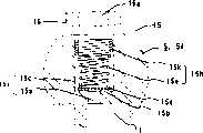
如图3以及图4所示,安全阀装置15具备释放流路15i、安全阀15d、阀推压体15h、以及限位器16。释放流路15i由释放孔15a和安全阀室15c构成,该释放流路15i形成于固定涡盘5的底板5d上而将压缩室11和喷出压室2f连通起来。安全阀15d用于对释放流路15i进行打开和关闭。阀推压体15h用于在安全阀15d关闭时将弹性推压力施加给安全阀15d,它设置在安全阀室15c内,配置在安全阀15d和限位器16之间。具备对安全阀室15c内的移动进行导向的导向部和产生弹性推压力的弹性部。限位器16用于限制阀推压体15h的移动范围,在过压缩时将阀推压体15h保持在规定位置。As shown in FIGS. 3 and 4 , the
与压缩室11连通的释放孔15a、圆环状的阀座15b、与喷出压室2f连通的安全阀室15c与固定涡盘5连续形成,构成连结压缩室11和喷出压室2f的释放流路15i。释放孔15a的直径小,安全阀室15c的直径大,在安全阀室15c的阶梯部上形成有阀座15b。即,释放孔15a、阀座15b、安全阀室15c在固定涡盘5的底板5d的厚度方向上形成。特别是,使释放孔15a的内径尺寸和长度尺寸极小,以缩小压缩室11的成为死容积的体积。另外,使安全阀室15c比释放孔15a直径大以使得能够做成可以充分确保功能的阀推压体15h的大小。The
并且,在安全阀室15c上配置了安全阀15d,该安全阀15d在压缩室11内的压力超过喷出压室2f的设定压力时打开以使压缩室11内的气体或流体逃逸到喷出压室2f。在释放孔15a的安全阀室15c侧,由圆盘状的弹簧钢板等做成的安全阀15d配置成与设在释放孔15a和安全阀室15c的交界面上的圆环状的阀座15b接触。Also, a
在安全阀15d的上部搭载由构成导向部的导向部件15f和构成弹性部的弹性部件15e组成的阀推压体15h。还有,阀推压体15h由薄钢板等做成,将弹性部件15e的一端压入导向部件15f的一部分中而一体组合起来构成。安全阀流路15i上下延伸而形成,安全阀15d承受阀推压体15h的负荷。打开安全阀15d是在过压缩到超过设定压力(喷出压力+安全阀15d的重量+弹性部件15e的重量+导向部件15f的重量)的情况。还有,“安全阀15d的重量+弹性部件15e的重量+导向部件15f的重量”所产生的推压力很小。A
导向部件15f具有比安全阀室15c的内径小一些的外径,可以在安全阀室15c内移动。弹性部件15e为盘簧,安装在导向部件15f上,与导向部件15f一起移动。该弹性部件15e在安全阀15d关闭释放流路15i的状态下为自由状态,并且在安全阀15d打开释放流路15i的状态下被压缩。在该情况下,所谓弹性部件15e的自由状态是指阀推压体15h不与限位器16接触的状态。这是来自限位器16的反作用力不施加到弹性部件15e上的状态。The
限位器16具有气体或液体的逃逸孔16a,利用螺栓18等与底板5d的上面具有间隙地安装在固定涡盘5的底板5d的上方。设在多个地方的安全阀装置15的限位器16由一个部件做成。The
在上述结构中,电动机4被驱动旋转,旋转涡盘6作旋转运动时,冷媒气体从吸入口2d被导向吸入室10和压缩室11,被压缩的气体从固定涡盘5的喷出口5e被排出到喷出压室2f,进一步从密闭容器2的排出口2e被排出到室内空调机等的冷冻循环的配管。In the above-mentioned structure, the
在冷媒气体被压缩的过程中,在压缩室11内的压力为设定压力(喷出压力+安全阀15d的重量+阀推压体15h的重量)以下的通常运转时,由于喷出压室2f的压力比压缩室11的压力高,所以因该压力差,安全阀15d与阀座15b接触,释放孔15a被闭路(参照图3)。在该闭路中,由于差压一直施加到安全阀15d的上面,所以该闭路被维持。这样,在通常运转时,工作流体不会从安全阀装置15喷出。这时,安全阀孔15a的容积成为压缩室11的容积的一部分,在压缩行程中,由于成为伴随着剩下的气体的再度膨胀损失的死容积,所以希望如前所述使该体积尽可能小。During normal operation in which the pressure in the
另一方面,在室内空调等的运转条件中冷媒气体或液体冷媒或润滑油被压缩的过程中,在压缩室11内的压力超过设定压力时(过压缩运转时),压缩室11的压力比喷出室2f的压力高,因该压力差,安全阀15d离开阀座15b,释放孔15a被打开(参照图4)。伴随着该安全阀15d的移动,阀推压体15h被导向部件15f引导而移动。进一步移动的话,导向部件15f接触到限位器15f,其移动受到限制,弹性部件15e被安全阀15d推压而被压缩。压缩室11内的工作流体如图4的空心箭头那样被喷出到喷出压室2f内。这样,能够防止过压缩损失和涡盘卷边的损伤。On the other hand, when the pressure in the
在该过压缩运转状态,伴随着旋转涡盘的旋转,压力在喷出压力以下的压缩室11接下来与释放孔15a连通,压缩室11的压力变得比喷出压室2f的压力低,因该差压和弹性部件15e的弹性推压力一起瞬间使安全阀29e关闭。这样,在过压缩运转时,重复图4和图3所示的状态。In this overcompression operation state, with the rotation of the orbiting scroll, the
在本实施例的涡旋压缩机1中,作为用于打开安全阀15d的设定压力,能够去除在原有的压缩机中因套筒的压入一直对安全阀施加负荷的弹性部件的压缩力,代之以仅阀推压体15h(弹性部件15e和导向部件15f)的自重所施加的负荷,可以显著地降低打开安全阀15d的设定压力,能够降低因安全阀15d的打开延迟而导致的压缩室11内的压力上升部分相应的电动机负荷,提高压缩机性能。还有,能够去除因原有的套筒压入孔和弹性部件的弹性常数等制作精度的偏差使得安全阀打开的压力变动而产生的压缩机性能的偏差,仅对构成阀推压体15h的导向部件15f和弹性部件15e的重量进行管理即可,能够使打开安全阀15d的设定压力稳定,可以提供性能稳定的涡旋压缩机1。In the
与构成基于以上说明过的本实施例的效果综合起来叙述的话,如下所述。The following will be described together with the effects of the present embodiment based on the configuration described above.
采用本实施例,由于阀推压体15h配置在安全阀15d和限位器16之间,具有在安全阀15d关闭释放流路的状态成为自由状态、并且在安全阀15d打开释放流路的状态被压缩的弹性部,能够防止安全阀15d打开的延迟,仅此即可相应抑制压缩室11内的压力上升,这样,能够减轻运转负荷并提高压缩机性能,同时,能够稳定地得到开始打开安全阀15d,这样,能够量产得到作为安全阀装置15的稳定功能。According to this embodiment, since the
另外,采用本实施例,释放流路15i具备:与压缩室11连通的释放孔15a;与释放孔15a以及喷出压室连通并且比释放孔15a直径大的安全阀室15c,阀推压体15h配置在安全阀室15c内,并具有对安全阀室内的移动进行导向的导向部和产生弹性推压力的弹性部,因此,能够缩小释放孔15a的体积并减少因释放孔15a导致的工作流体的再膨胀损失,在大直径的安全阀室15c内可靠地移动阀推压体15h,这样,能够得到高性能、高可靠性。In addition, according to the present embodiment, the
再有,采用本实施例,由于导向部是以具有比安全阀室15c的内径小一些的外径的导向部件15f形成,弹性部是以安装在导向部件15f上的盘簧15e形成,所以能够以廉价可靠性高的盘簧15e得到弹性推压力,同时做成具有适当的导向功能的导向部件15f。Furthermore, with this embodiment, since the guide portion is formed by the
并且,采用本实施例,由于导向部件15f具有可以移动所述安全阀室的间隙的外径,同时开口有使被加压到喷出压室2f的设定压力以上的气体或液体逃逸的通路,所以能够同时实现可靠的导向功能与可靠的气体或液体的排放功能。And, adopt this embodiment, because
再有,采用本实施例,由于安全阀装置15与形成于压缩机构部3的多个压缩室11对应而在多个地方形成,以同一部件构成这些安全阀装置15的限位器16,所以能够以廉价的结构可靠地防止过压缩。Furthermore, according to this embodiment, since the
再有,采用本实施例,由于旋转涡盘6以及固定涡盘5上下咬合,释放流路15i在上下延伸而形成,安全阀15d承受导向部件15f以及盘簧15e的负荷,所以虽然导向部件15f以及盘簧15e的负荷很小也能够施加到安全阀15d的闭路中,这样,完全不增大损失就能够确保安全阀15d可靠的闭路性能。Furthermore, according to this embodiment, since the orbiting scroll 6 and the fixed
其次,用图7以及图8对本发明的第2实施例进行说明。图7是本发明第2实施例的涡旋压缩机的安全阀装置15在闭路状态的剖面图,图8是图7的安全阀装置15在开路状态的剖面图。该第2实施例在以下所述的几点与第1实施例不同,其它之点与第1实施例基本相同。Next, a second embodiment of the present invention will be described with reference to FIGS. 7 and 8 . 7 is a cross-sectional view of the
在该第2实施例中,阀推压体15h以具有构成导向部的紧密缠绕部15k和构成弹性部的可伸缩部15e的一个盘簧15h形成。即,图7虽然是安全阀15d关闭的状态,但阀推压体15h的上部的紧密缠绕部15k以在安全阀室15c内径顺畅地移动的外径尺寸紧密缠绕成线圈状做成,下部的可伸缩部15e用于起到对气体或流体从释放孔15a逃逸时的推压的缓冲作用和在气体或流体逃逸后瞬间地压回安全阀15d来关闭的作用。还有,可伸缩部15e比紧密缠绕部15k外径更细,承受负荷时,可伸缩部15e收缩直径变大,也不会接触到安全阀室15c内壁。图8所示的是压缩时11的压力比喷出压室2f压力大成为过压缩而打开安全阀15d,为了如空心箭头所示那样使气体或流体逃逸,安全阀15d和阀推压体15h上升时与防脱的限位器16接触的状态。In this second embodiment, the
采用该第2实施例,由于阀推压体以具有构成导向部的紧密缠绕部和构成弹性部的可伸缩部的一个盘簧形成,所以能够做成极廉价的阀推压体。According to the second embodiment, since the valve pressing body is formed of one coil spring having the closely wound portion constituting the guide portion and the stretchable portion constituting the elastic portion, an extremely inexpensive valve pressing body can be made.
其次,用图9以及图10对本发明的第3实施例进行说明。图9是本发明的第3实施例的涡旋压缩机的安全阀装置15在闭路状态的剖面图,图10是图9的安全阀装置15在开路状态的剖面图。该第3实施例在以下所述的几点与第1实施例不同,其它之点与第1实施例基本相同。Next, a third embodiment of the present invention will be described with reference to FIGS. 9 and 10 . 9 is a cross-sectional view of a
在该第3实施例中,以圆柱体形成导向部件15f,在圆柱体的中央形成逃逸孔15g,同时,在其周围形成多个逃逸孔151。由于该导向部件15f是与原有的套筒类似的结构,能够利用生产设备,同时,能够确保与原来同样的使工作流体从导向部件15f逃逸的性能。In this third embodiment, the
另外,在构成弹性部件15e的盘簧的两端设置紧密缠绕部。通过使该两端为紧密缠绕部,由于在与导向部件15f的组装时盘簧的组装方向不只是在一个方向,组装性良好。另外,利用紧密缠绕部,难以从导向部件15f脱落,能够以廉价的结构提高组装性,防止盘簧的脱落。In addition, closely wound portions are provided at both ends of the coil spring constituting the
采用本实施方式,使弹性部件15e的自然长度与直径之比为1∶0.8~4.0,使其弹性部件15e的可伸缩长度、圆环状阀座15b的直径、安全阀室15c的内径、以及安全阀15d的外径的比率为1∶3以下∶5以下∶3以上。通过这样的关系,能够在安全阀15d从阀座15b离开而打开释放流路15i时,防止安全阀15d在释放流路15i姿势崩溃而挂住。Adopt present embodiment, make the natural length of
另外,采用本实施方式,通过使释放孔15a、阀座通路15n、安全阀周围通路15j、逃逸通路15m的流路面积比为1∶1~10∶1~15∶1~20,能够降低安全阀装置15的流路阻力。In addition, according to this embodiment, by setting the flow area ratio of the
如图9以及图10所示的导向部件15f通过使烧结金属或树脂成形得到,以细长的形状也能够廉价地制作。The
另外,如以第3实施例为代表所示那样的(其它实施例也是),限位器16与固定涡盘5的底板5d不必一定要有间隙。另外,同样地以第3实施例为代表那样地使安全阀室15c做成两段形状,通过把导向部或导向部件根据需要做成限制接近释放孔侧的结构,能够防止导向部或导向部件在安全阀室内很大地振动,产生与限位器16的撞击声。In addition, as represented by the third embodiment (and other embodiments as well), there is not necessarily a gap between the
如上所述,采用应用了本发明的实施方式的涡旋压缩机,能够防止安全阀打开的延迟,以小的死容积降低排出过压缩气体或液体冷媒时的流路阻力,降低运转负荷并提高压缩机性能。另外,能够防止安全阀的挂住,量产且廉价地得到可靠性高稳定的安全阀功能。As described above, with the scroll compressor to which the embodiment of the present invention is applied, it is possible to prevent the delay in the opening of the safety valve, reduce the flow path resistance when discharging the overcompressed gas or liquid refrigerant with a small dead volume, reduce the operating load and improve the operating load. compressor performance. In addition, it is possible to prevent the safety valve from being caught, and to mass-produce and obtain a highly reliable and stable safety valve function at low cost.
Claims (11)
Translated fromChineseApplications Claiming Priority (2)
| Application Number | Priority Date | Filing Date | Title |
|---|---|---|---|
| JP2004158814 | 2004-05-28 | ||
| JP2004158814 | 2004-05-28 |
Publications (2)
| Publication Number | Publication Date |
|---|---|
| CN1702328Atrue CN1702328A (en) | 2005-11-30 |
| CN100376798C CN100376798C (en) | 2008-03-26 |
Family
ID=35632245
Family Applications (1)
| Application Number | Title | Priority Date | Filing Date |
|---|---|---|---|
| CNB2005100629936AExpired - Fee RelatedCN100376798C (en) | 2004-05-28 | 2005-04-04 | scroll compressor |
Country Status (3)
| Country | Link |
|---|---|
| JP (1) | JP5171899B2 (en) |
| KR (1) | KR100730250B1 (en) |
| CN (1) | CN100376798C (en) |
Cited By (38)
| Publication number | Priority date | Publication date | Assignee | Title |
|---|---|---|---|---|
| CN102269165A (en)* | 2010-06-07 | 2011-12-07 | 蒋友荣 | Dual-use high-performance oil-free vortex compressor for gas medium and liquid medium |
| CN102878078A (en)* | 2011-07-12 | 2013-01-16 | 日立空调·家用电器株式会社 | Scroll compressor |
| CN103016345A (en)* | 2008-01-16 | 2013-04-03 | 艾默生环境优化技术有限公司 | Scroll machine |
| CN103375401A (en)* | 2012-04-27 | 2013-10-30 | 日立空调·家用电器株式会社 | Hermetic compressor |
| CN103452850A (en)* | 2013-09-10 | 2013-12-18 | 陕西赛恩斯压缩机有限公司 | Device for preventing gas backflow of scroll air compressor |
| CN104061155A (en)* | 2013-03-19 | 2014-09-24 | 日立空调·家用电器株式会社 | Scroll compressor |
| CN104797821A (en)* | 2012-11-15 | 2015-07-22 | 艾默生环境优化技术有限公司 | Compressor valve system and assembly |
| CN104989641A (en)* | 2015-06-15 | 2015-10-21 | 东北大学 | Vortex dry vacuum pump |
| CN105673491A (en)* | 2014-12-08 | 2016-06-15 | 日立空调·家用电器株式会社 | Sealed electric compressor and air conditioner |
| US9435340B2 (en) | 2012-11-30 | 2016-09-06 | Emerson Climate Technologies, Inc. | Scroll compressor with variable volume ratio port in orbiting scroll |
| US9494157B2 (en) | 2012-11-30 | 2016-11-15 | Emerson Climate Technologies, Inc. | Compressor with capacity modulation and variable volume ratio |
| US9790940B2 (en) | 2015-03-19 | 2017-10-17 | Emerson Climate Technologies, Inc. | Variable volume ratio compressor |
| US9879674B2 (en) | 2009-04-07 | 2018-01-30 | Emerson Climate Technologies, Inc. | Compressor having capacity modulation assembly |
| US9989057B2 (en) | 2014-06-03 | 2018-06-05 | Emerson Climate Technologies, Inc. | Variable volume ratio scroll compressor |
| US10066622B2 (en) | 2015-10-29 | 2018-09-04 | Emerson Climate Technologies, Inc. | Compressor having capacity modulation system |
| US10094380B2 (en) | 2012-11-15 | 2018-10-09 | Emerson Climate Technologies, Inc. | Compressor |
| US10378540B2 (en) | 2015-07-01 | 2019-08-13 | Emerson Climate Technologies, Inc. | Compressor with thermally-responsive modulation system |
| CN110269555A (en)* | 2018-03-16 | 2019-09-24 | 青岛海尔洗碗机有限公司 | A kind of spray structure of dish-washing machine |
| CN110269570A (en)* | 2018-03-16 | 2019-09-24 | 青岛海尔洗碗机有限公司 | A kind of spray structure of dish-washing machine |
| CN110269564A (en)* | 2018-03-16 | 2019-09-24 | 青岛海尔洗碗机有限公司 | A kind of spray structure of dish-washing machine |
| CN110269569A (en)* | 2018-03-16 | 2019-09-24 | 青岛海尔洗碗机有限公司 | A kind of spray structure of dish-washing machine |
| WO2020103681A1 (en)* | 2018-11-22 | 2020-05-28 | 艾默生环境优化技术(苏州)有限公司 | Vortex expander |
| US10753352B2 (en) | 2017-02-07 | 2020-08-25 | Emerson Climate Technologies, Inc. | Compressor discharge valve assembly |
| US10801495B2 (en) | 2016-09-08 | 2020-10-13 | Emerson Climate Technologies, Inc. | Oil flow through the bearings of a scroll compressor |
| US10890186B2 (en) | 2016-09-08 | 2021-01-12 | Emerson Climate Technologies, Inc. | Compressor |
| US10962008B2 (en) | 2017-12-15 | 2021-03-30 | Emerson Climate Technologies, Inc. | Variable volume ratio compressor |
| US10995753B2 (en) | 2018-05-17 | 2021-05-04 | Emerson Climate Technologies, Inc. | Compressor having capacity modulation assembly |
| US11022119B2 (en) | 2017-10-03 | 2021-06-01 | Emerson Climate Technologies, Inc. | Variable volume ratio compressor |
| CN113606136A (en)* | 2021-08-27 | 2021-11-05 | 珠海格力电器股份有限公司 | Compressor and air conditioner with same |
| US11396873B2 (en) | 2019-12-27 | 2022-07-26 | Danfoss (Tianjin) Ltd. | Scroll compressor comprising a valve provided on a fixed scroll that opens at a certain pressure |
| US11655813B2 (en) | 2021-07-29 | 2023-05-23 | Emerson Climate Technologies, Inc. | Compressor modulation system with multi-way valve |
| US11846287B1 (en) | 2022-08-11 | 2023-12-19 | Copeland Lp | Scroll compressor with center hub |
| WO2024002351A1 (en)* | 2022-06-30 | 2024-01-04 | 谷轮环境科技(苏州)有限公司 | Compression mechanism, scroll compressor and control method for scroll compressor |
| US11965507B1 (en) | 2022-12-15 | 2024-04-23 | Copeland Lp | Compressor and valve assembly |
| US12163523B1 (en) | 2023-12-15 | 2024-12-10 | Copeland Lp | Compressor and valve assembly |
| US12173708B1 (en) | 2023-12-07 | 2024-12-24 | Copeland Lp | Heat pump systems with capacity modulation |
| US12259163B2 (en) | 2022-06-01 | 2025-03-25 | Copeland Lp | Climate-control system with thermal storage |
| US12416308B2 (en) | 2022-12-28 | 2025-09-16 | Copeland Lp | Compressor with shutdown assembly |
Families Citing this family (3)
| Publication number | Priority date | Publication date | Assignee | Title |
|---|---|---|---|---|
| JP5396235B2 (en)* | 2009-10-26 | 2014-01-22 | 日立アプライアンス株式会社 | Scroll compressor |
| DE102012222823A1 (en) | 2012-06-28 | 2014-01-02 | Robert Bosch Gmbh | Piston fuel pump |
| CN110966184A (en)* | 2019-12-19 | 2020-04-07 | 苏州旋凌科技有限公司 | Scroll with active pressure relief structure |
Family Cites Families (13)
| Publication number | Priority date | Publication date | Assignee | Title |
|---|---|---|---|---|
| CA1014043A (en)* | 1973-09-04 | 1977-07-19 | Caterpillar Tractor Co. | Restrictor valve |
| US5203857A (en)* | 1990-06-01 | 1993-04-20 | Bristol Compressors, Inc. | Gas compressor head and discharge valve construction |
| US5173042A (en)* | 1991-11-04 | 1992-12-22 | General Motors Corporation | Scroll compressor and discharge valve |
| JPH08319973A (en)* | 1995-05-26 | 1996-12-03 | Hitachi Ltd | Compressor and its discharge valve device |
| JP3745801B2 (en)* | 1995-10-11 | 2006-02-15 | 株式会社日本自動車部品総合研究所 | Scroll compressor and injection cycle |
| JP2001082338A (en)* | 1999-09-20 | 2001-03-27 | Toyota Autom Loom Works Ltd | Flow passage opening and closing device for compressor |
| JP3818004B2 (en)* | 2000-03-02 | 2006-09-06 | 三菱電機株式会社 | Scroll compressor |
| JP2001323881A (en)* | 2000-05-16 | 2001-11-22 | Hitachi Ltd | Compressor |
| KR20020029211A (en)* | 2000-10-12 | 2002-04-18 | 구자홍 | by-pass valve device in scroll compressor |
| JP2002221171A (en)* | 2001-01-23 | 2002-08-09 | Hitachi Ltd | Scroll compressor |
| KR100425106B1 (en)* | 2001-10-11 | 2004-03-30 | 엘지전자 주식회사 | Bypass device for scroll compressor |
| JP2003184762A (en)* | 2001-12-20 | 2003-07-03 | Fujitsu General Ltd | Scroll compressor |
| JP4644495B2 (en)* | 2004-05-28 | 2011-03-02 | 日立アプライアンス株式会社 | Scroll compressor |
- 2005
- 2005-04-04CNCNB2005100629936Apatent/CN100376798C/ennot_activeExpired - Fee Related
- 2005-04-14KRKR1020050030870Apatent/KR100730250B1/ennot_activeExpired - Fee Related
- 2010
- 2010-08-03JPJP2010174080Apatent/JP5171899B2/ennot_activeExpired - Fee Related
Cited By (59)
| Publication number | Priority date | Publication date | Assignee | Title |
|---|---|---|---|---|
| CN103016345A (en)* | 2008-01-16 | 2013-04-03 | 艾默生环境优化技术有限公司 | Scroll machine |
| CN103016345B (en)* | 2008-01-16 | 2015-10-21 | 艾默生环境优化技术有限公司 | Scroll machine |
| US9879674B2 (en) | 2009-04-07 | 2018-01-30 | Emerson Climate Technologies, Inc. | Compressor having capacity modulation assembly |
| US10954940B2 (en) | 2009-04-07 | 2021-03-23 | Emerson Climate Technologies, Inc. | Compressor having capacity modulation assembly |
| US11635078B2 (en) | 2009-04-07 | 2023-04-25 | Emerson Climate Technologies, Inc. | Compressor having capacity modulation assembly |
| CN102269165A (en)* | 2010-06-07 | 2011-12-07 | 蒋友荣 | Dual-use high-performance oil-free vortex compressor for gas medium and liquid medium |
| CN102878078A (en)* | 2011-07-12 | 2013-01-16 | 日立空调·家用电器株式会社 | Scroll compressor |
| CN102878078B (en)* | 2011-07-12 | 2015-09-09 | 日立空调·家用电器株式会社 | Scroll compressor |
| CN103375401A (en)* | 2012-04-27 | 2013-10-30 | 日立空调·家用电器株式会社 | Hermetic compressor |
| US11434910B2 (en) | 2012-11-15 | 2022-09-06 | Emerson Climate Technologies, Inc. | Scroll compressor having hub plate |
| US10094380B2 (en) | 2012-11-15 | 2018-10-09 | Emerson Climate Technologies, Inc. | Compressor |
| US10907633B2 (en) | 2012-11-15 | 2021-02-02 | Emerson Climate Technologies, Inc. | Scroll compressor having hub plate |
| US9651043B2 (en) | 2012-11-15 | 2017-05-16 | Emerson Climate Technologies, Inc. | Compressor valve system and assembly |
| US10495086B2 (en) | 2012-11-15 | 2019-12-03 | Emerson Climate Technologies, Inc. | Compressor valve system and assembly |
| CN104797821A (en)* | 2012-11-15 | 2015-07-22 | 艾默生环境优化技术有限公司 | Compressor valve system and assembly |
| US9435340B2 (en) | 2012-11-30 | 2016-09-06 | Emerson Climate Technologies, Inc. | Scroll compressor with variable volume ratio port in orbiting scroll |
| US9494157B2 (en) | 2012-11-30 | 2016-11-15 | Emerson Climate Technologies, Inc. | Compressor with capacity modulation and variable volume ratio |
| US9777730B2 (en) | 2012-11-30 | 2017-10-03 | Emerson Climate Technologies, Inc. | Scroll compressor with variable volume ratio port in orbiting scroll |
| CN104061155B (en)* | 2013-03-19 | 2016-06-08 | 日立空调·家用电器株式会社 | Scroll compressor |
| CN104061155A (en)* | 2013-03-19 | 2014-09-24 | 日立空调·家用电器株式会社 | Scroll compressor |
| CN103452850A (en)* | 2013-09-10 | 2013-12-18 | 陕西赛恩斯压缩机有限公司 | Device for preventing gas backflow of scroll air compressor |
| US9989057B2 (en) | 2014-06-03 | 2018-06-05 | Emerson Climate Technologies, Inc. | Variable volume ratio scroll compressor |
| CN105673491A (en)* | 2014-12-08 | 2016-06-15 | 日立空调·家用电器株式会社 | Sealed electric compressor and air conditioner |
| CN105673491B (en)* | 2014-12-08 | 2017-12-26 | 江森自控日立空调技术(香港)有限公司 | Sealed electric compressor and air conditioner |
| US9790940B2 (en) | 2015-03-19 | 2017-10-17 | Emerson Climate Technologies, Inc. | Variable volume ratio compressor |
| US10323638B2 (en) | 2015-03-19 | 2019-06-18 | Emerson Climate Technologies, Inc. | Variable volume ratio compressor |
| US10323639B2 (en) | 2015-03-19 | 2019-06-18 | Emerson Climate Technologies, Inc. | Variable volume ratio compressor |
| CN104989641A (en)* | 2015-06-15 | 2015-10-21 | 东北大学 | Vortex dry vacuum pump |
| US10378540B2 (en) | 2015-07-01 | 2019-08-13 | Emerson Climate Technologies, Inc. | Compressor with thermally-responsive modulation system |
| US10087936B2 (en) | 2015-10-29 | 2018-10-02 | Emerson Climate Technologies, Inc. | Compressor having capacity modulation system |
| US10066622B2 (en) | 2015-10-29 | 2018-09-04 | Emerson Climate Technologies, Inc. | Compressor having capacity modulation system |
| US10801495B2 (en) | 2016-09-08 | 2020-10-13 | Emerson Climate Technologies, Inc. | Oil flow through the bearings of a scroll compressor |
| US10890186B2 (en) | 2016-09-08 | 2021-01-12 | Emerson Climate Technologies, Inc. | Compressor |
| US10753352B2 (en) | 2017-02-07 | 2020-08-25 | Emerson Climate Technologies, Inc. | Compressor discharge valve assembly |
| US11022119B2 (en) | 2017-10-03 | 2021-06-01 | Emerson Climate Technologies, Inc. | Variable volume ratio compressor |
| US10962008B2 (en) | 2017-12-15 | 2021-03-30 | Emerson Climate Technologies, Inc. | Variable volume ratio compressor |
| CN110269564A (en)* | 2018-03-16 | 2019-09-24 | 青岛海尔洗碗机有限公司 | A kind of spray structure of dish-washing machine |
| CN110269555A (en)* | 2018-03-16 | 2019-09-24 | 青岛海尔洗碗机有限公司 | A kind of spray structure of dish-washing machine |
| CN110269570A (en)* | 2018-03-16 | 2019-09-24 | 青岛海尔洗碗机有限公司 | A kind of spray structure of dish-washing machine |
| CN110269569A (en)* | 2018-03-16 | 2019-09-24 | 青岛海尔洗碗机有限公司 | A kind of spray structure of dish-washing machine |
| CN110269570B (en)* | 2018-03-16 | 2022-06-21 | 青岛海尔洗碗机有限公司 | A spray structure of a dishwasher |
| CN110269564B (en)* | 2018-03-16 | 2022-06-21 | 青岛海尔洗碗机有限公司 | A spray structure of a dishwasher |
| US10995753B2 (en) | 2018-05-17 | 2021-05-04 | Emerson Climate Technologies, Inc. | Compressor having capacity modulation assembly |
| US11754072B2 (en) | 2018-05-17 | 2023-09-12 | Copeland Lp | Compressor having capacity modulation assembly |
| US11391154B2 (en) | 2018-11-22 | 2022-07-19 | Emerson Climate Technologies (Suzhou) Co., Ltd. | Scroll expander with back pressure chamber |
| WO2020103681A1 (en)* | 2018-11-22 | 2020-05-28 | 艾默生环境优化技术(苏州)有限公司 | Vortex expander |
| US11396873B2 (en) | 2019-12-27 | 2022-07-26 | Danfoss (Tianjin) Ltd. | Scroll compressor comprising a valve provided on a fixed scroll that opens at a certain pressure |
| US11655813B2 (en) | 2021-07-29 | 2023-05-23 | Emerson Climate Technologies, Inc. | Compressor modulation system with multi-way valve |
| US11879460B2 (en) | 2021-07-29 | 2024-01-23 | Copeland Lp | Compressor modulation system with multi-way valve |
| CN113606136B (en)* | 2021-08-27 | 2022-11-15 | 珠海格力电器股份有限公司 | Compressor and air conditioner with same |
| CN113606136A (en)* | 2021-08-27 | 2021-11-05 | 珠海格力电器股份有限公司 | Compressor and air conditioner with same |
| US12259163B2 (en) | 2022-06-01 | 2025-03-25 | Copeland Lp | Climate-control system with thermal storage |
| WO2024002351A1 (en)* | 2022-06-30 | 2024-01-04 | 谷轮环境科技(苏州)有限公司 | Compression mechanism, scroll compressor and control method for scroll compressor |
| US11846287B1 (en) | 2022-08-11 | 2023-12-19 | Copeland Lp | Scroll compressor with center hub |
| US12188470B2 (en) | 2022-08-11 | 2025-01-07 | Copeland Lp | Scroll compressor with center hub |
| US11965507B1 (en) | 2022-12-15 | 2024-04-23 | Copeland Lp | Compressor and valve assembly |
| US12416308B2 (en) | 2022-12-28 | 2025-09-16 | Copeland Lp | Compressor with shutdown assembly |
| US12173708B1 (en) | 2023-12-07 | 2024-12-24 | Copeland Lp | Heat pump systems with capacity modulation |
| US12163523B1 (en) | 2023-12-15 | 2024-12-10 | Copeland Lp | Compressor and valve assembly |
Also Published As
| Publication number | Publication date |
|---|---|
| KR20060045684A (en) | 2006-05-17 |
| KR100730250B1 (en) | 2007-06-20 |
| CN100376798C (en) | 2008-03-26 |
| JP5171899B2 (en) | 2013-03-27 |
| JP2010270762A (en) | 2010-12-02 |
Similar Documents
| Publication | Publication Date | Title |
|---|---|---|
| CN1702328A (en) | Vortex compressor | |
| CN1865705A (en) | Scroll compressor | |
| CN1246590C (en) | Vacuumproof device for vortex type compressor | |
| CN1034830C (en) | scroll compressor | |
| CN1267646C (en) | Antivacuum device for vortex compressor | |
| CN1276180C (en) | Vaccum preventing device for vortex complessor | |
| CN1205412C (en) | scroll compressor | |
| CN1249350C (en) | Vacuum-protective device for vortex compressor | |
| JP5463330B2 (en) | Scroll compressor | |
| CN1578878A (en) | Compressor | |
| CN1940292A (en) | Hermetic compressor | |
| CN1221739C (en) | Vortex compressor | |
| CN1215261C (en) | Vortex compressor | |
| CN100340768C (en) | Vortex compressor | |
| CN1860295A (en) | Compressor and suction valve structure | |
| CN1616828A (en) | Fluid compressor | |
| CN1450266A (en) | Cylinder assembly of hermetic compressor | |
| CN1789726A (en) | Back pressure apparatus for orbiting vane compressors | |
| CN1637298A (en) | Compressor | |
| JP4644495B2 (en) | Scroll compressor | |
| US20060078451A1 (en) | Scroll compressor | |
| KR102549139B1 (en) | Compressor | |
| KR20120045958A (en) | Compressor | |
| KR100253209B1 (en) | Structure for guiding active gas in hermetic type rotary compressor | |
| CN1815025A (en) | Horizontal type orbiting vane compressor |
Legal Events
| Date | Code | Title | Description |
|---|---|---|---|
| C06 | Publication | ||
| PB01 | Publication | ||
| C10 | Entry into substantive examination | ||
| SE01 | Entry into force of request for substantive examination | ||
| C14 | Grant of patent or utility model | ||
| GR01 | Patent grant | ||
| C41 | Transfer of patent application or patent right or utility model | ||
| TR01 | Transfer of patent right | Effective date of registration:20160826 Address after:Hongkong aoteng Plaza No. 8 Chinese Kowloon Linze street 12 floor Patentee after:Johnson Controls Hitachi air conditioning technology (Hong Kong) Co.,Ltd. Address before:Tokyo, Japan Patentee before:Hitachi Appliances, Inc. | |
| TR01 | Transfer of patent right | ||
| TR01 | Transfer of patent right | Effective date of registration:20180705 Address after:Tokyo, Japan Patentee after:HITACHI-JOHNSON CONTROLS AIR CONDITIONING, Inc. Address before:Hongkong aoteng Plaza No. 8 Chinese Kowloon Linze street 12 floor Patentee before:Johnson Controls Hitachi air conditioning technology (Hong Kong) Co.,Ltd. | |
| CF01 | Termination of patent right due to non-payment of annual fee | ||
| CF01 | Termination of patent right due to non-payment of annual fee | Granted publication date:20080326 |