CN1701242A - Obstacle detection device - Google Patents
Obstacle detection deviceDownload PDFInfo
- Publication number
- CN1701242A CN1701242ACNA2004800007363ACN200480000736ACN1701242ACN 1701242 ACN1701242 ACN 1701242ACN A2004800007363 ACNA2004800007363 ACN A2004800007363ACN 200480000736 ACN200480000736 ACN 200480000736ACN 1701242 ACN1701242 ACN 1701242A
- Authority
- CN
- China
- Prior art keywords
- obstacle
- section
- distance
- image
- detection device
- Prior art date
- Legal status (The legal status is an assumption and is not a legal conclusion. Google has not performed a legal analysis and makes no representation as to the accuracy of the status listed.)
- Pending
Links
Images


Classifications
- G—PHYSICS
- G01—MEASURING; TESTING
- G01S—RADIO DIRECTION-FINDING; RADIO NAVIGATION; DETERMINING DISTANCE OR VELOCITY BY USE OF RADIO WAVES; LOCATING OR PRESENCE-DETECTING BY USE OF THE REFLECTION OR RERADIATION OF RADIO WAVES; ANALOGOUS ARRANGEMENTS USING OTHER WAVES
- G01S13/00—Systems using the reflection or reradiation of radio waves, e.g. radar systems; Analogous systems using reflection or reradiation of waves whose nature or wavelength is irrelevant or unspecified
- G01S13/88—Radar or analogous systems specially adapted for specific applications
- G01S13/93—Radar or analogous systems specially adapted for specific applications for anti-collision purposes
- G—PHYSICS
- G06—COMPUTING OR CALCULATING; COUNTING
- G06V—IMAGE OR VIDEO RECOGNITION OR UNDERSTANDING
- G06V20/00—Scenes; Scene-specific elements
- G06V20/50—Context or environment of the image
- G06V20/56—Context or environment of the image exterior to a vehicle by using sensors mounted on the vehicle
- G06V20/58—Recognition of moving objects or obstacles, e.g. vehicles or pedestrians; Recognition of traffic objects, e.g. traffic signs, traffic lights or roads
- G06V20/586—Recognition of moving objects or obstacles, e.g. vehicles or pedestrians; Recognition of traffic objects, e.g. traffic signs, traffic lights or roads of parking space
- B—PERFORMING OPERATIONS; TRANSPORTING
- B60—VEHICLES IN GENERAL
- B60R—VEHICLES, VEHICLE FITTINGS, OR VEHICLE PARTS, NOT OTHERWISE PROVIDED FOR
- B60R21/00—Arrangements or fittings on vehicles for protecting or preventing injuries to occupants or pedestrians in case of accidents or other traffic risks
- B—PERFORMING OPERATIONS; TRANSPORTING
- B62—LAND VEHICLES FOR TRAVELLING OTHERWISE THAN ON RAILS
- B62D—MOTOR VEHICLES; TRAILERS
- B62D15/00—Steering not otherwise provided for
- B62D15/02—Steering position indicators ; Steering position determination; Steering aids
- B62D15/027—Parking aids, e.g. instruction means
- G—PHYSICS
- G01—MEASURING; TESTING
- G01S—RADIO DIRECTION-FINDING; RADIO NAVIGATION; DETERMINING DISTANCE OR VELOCITY BY USE OF RADIO WAVES; LOCATING OR PRESENCE-DETECTING BY USE OF THE REFLECTION OR RERADIATION OF RADIO WAVES; ANALOGOUS ARRANGEMENTS USING OTHER WAVES
- G01S13/00—Systems using the reflection or reradiation of radio waves, e.g. radar systems; Analogous systems using reflection or reradiation of waves whose nature or wavelength is irrelevant or unspecified
- G01S13/88—Radar or analogous systems specially adapted for specific applications
- G01S13/93—Radar or analogous systems specially adapted for specific applications for anti-collision purposes
- G01S13/931—Radar or analogous systems specially adapted for specific applications for anti-collision purposes of land vehicles
- G—PHYSICS
- G05—CONTROLLING; REGULATING
- G05D—SYSTEMS FOR CONTROLLING OR REGULATING NON-ELECTRIC VARIABLES
- G05D1/00—Control of position, course, altitude or attitude of land, water, air or space vehicles, e.g. using automatic pilots
- G05D1/02—Control of position or course in two dimensions
- G05D1/021—Control of position or course in two dimensions specially adapted to land vehicles
- G05D1/0231—Control of position or course in two dimensions specially adapted to land vehicles using optical position detecting means
- G05D1/0238—Control of position or course in two dimensions specially adapted to land vehicles using optical position detecting means using obstacle or wall sensors
- G—PHYSICS
- G08—SIGNALLING
- G08G—TRAFFIC CONTROL SYSTEMS
- G08G1/00—Traffic control systems for road vehicles
- G08G1/16—Anti-collision systems
- B—PERFORMING OPERATIONS; TRANSPORTING
- B60—VEHICLES IN GENERAL
- B60T—VEHICLE BRAKE CONTROL SYSTEMS OR PARTS THEREOF; BRAKE CONTROL SYSTEMS OR PARTS THEREOF, IN GENERAL; ARRANGEMENT OF BRAKING ELEMENTS ON VEHICLES IN GENERAL; PORTABLE DEVICES FOR PREVENTING UNWANTED MOVEMENT OF VEHICLES; VEHICLE MODIFICATIONS TO FACILITATE COOLING OF BRAKES
- B60T2201/00—Particular use of vehicle brake systems; Special systems using also the brakes; Special software modules within the brake system controller
- B60T2201/10—Automatic or semi-automatic parking aid systems
- G—PHYSICS
- G01—MEASURING; TESTING
- G01S—RADIO DIRECTION-FINDING; RADIO NAVIGATION; DETERMINING DISTANCE OR VELOCITY BY USE OF RADIO WAVES; LOCATING OR PRESENCE-DETECTING BY USE OF THE REFLECTION OR RERADIATION OF RADIO WAVES; ANALOGOUS ARRANGEMENTS USING OTHER WAVES
- G01S13/00—Systems using the reflection or reradiation of radio waves, e.g. radar systems; Analogous systems using reflection or reradiation of waves whose nature or wavelength is irrelevant or unspecified
- G01S13/88—Radar or analogous systems specially adapted for specific applications
- G01S13/93—Radar or analogous systems specially adapted for specific applications for anti-collision purposes
- G01S13/931—Radar or analogous systems specially adapted for specific applications for anti-collision purposes of land vehicles
- G01S2013/9314—Parking operations
- G—PHYSICS
- G01—MEASURING; TESTING
- G01S—RADIO DIRECTION-FINDING; RADIO NAVIGATION; DETERMINING DISTANCE OR VELOCITY BY USE OF RADIO WAVES; LOCATING OR PRESENCE-DETECTING BY USE OF THE REFLECTION OR RERADIATION OF RADIO WAVES; ANALOGOUS ARRANGEMENTS USING OTHER WAVES
- G01S13/00—Systems using the reflection or reradiation of radio waves, e.g. radar systems; Analogous systems using reflection or reradiation of waves whose nature or wavelength is irrelevant or unspecified
- G01S13/88—Radar or analogous systems specially adapted for specific applications
- G01S13/93—Radar or analogous systems specially adapted for specific applications for anti-collision purposes
- G01S13/931—Radar or analogous systems specially adapted for specific applications for anti-collision purposes of land vehicles
- G01S2013/9327—Sensor installation details
- G01S2013/93271—Sensor installation details in the front of the vehicles
- G—PHYSICS
- G01—MEASURING; TESTING
- G01S—RADIO DIRECTION-FINDING; RADIO NAVIGATION; DETERMINING DISTANCE OR VELOCITY BY USE OF RADIO WAVES; LOCATING OR PRESENCE-DETECTING BY USE OF THE REFLECTION OR RERADIATION OF RADIO WAVES; ANALOGOUS ARRANGEMENTS USING OTHER WAVES
- G01S13/00—Systems using the reflection or reradiation of radio waves, e.g. radar systems; Analogous systems using reflection or reradiation of waves whose nature or wavelength is irrelevant or unspecified
- G01S13/88—Radar or analogous systems specially adapted for specific applications
- G01S13/93—Radar or analogous systems specially adapted for specific applications for anti-collision purposes
- G01S13/931—Radar or analogous systems specially adapted for specific applications for anti-collision purposes of land vehicles
- G01S2013/9327—Sensor installation details
- G01S2013/93272—Sensor installation details in the back of the vehicles
- G—PHYSICS
- G01—MEASURING; TESTING
- G01S—RADIO DIRECTION-FINDING; RADIO NAVIGATION; DETERMINING DISTANCE OR VELOCITY BY USE OF RADIO WAVES; LOCATING OR PRESENCE-DETECTING BY USE OF THE REFLECTION OR RERADIATION OF RADIO WAVES; ANALOGOUS ARRANGEMENTS USING OTHER WAVES
- G01S13/00—Systems using the reflection or reradiation of radio waves, e.g. radar systems; Analogous systems using reflection or reradiation of waves whose nature or wavelength is irrelevant or unspecified
- G01S13/88—Radar or analogous systems specially adapted for specific applications
- G01S13/93—Radar or analogous systems specially adapted for specific applications for anti-collision purposes
- G01S13/931—Radar or analogous systems specially adapted for specific applications for anti-collision purposes of land vehicles
- G01S2013/9327—Sensor installation details
- G01S2013/93274—Sensor installation details on the side of the vehicles
Landscapes
- Engineering & Computer Science (AREA)
- Physics & Mathematics (AREA)
- Remote Sensing (AREA)
- Radar, Positioning & Navigation (AREA)
- General Physics & Mathematics (AREA)
- Electromagnetism (AREA)
- Mechanical Engineering (AREA)
- Computer Networks & Wireless Communication (AREA)
- Chemical & Material Sciences (AREA)
- Transportation (AREA)
- Combustion & Propulsion (AREA)
- Multimedia (AREA)
- Theoretical Computer Science (AREA)
- Aviation & Aerospace Engineering (AREA)
- Automation & Control Theory (AREA)
- Radar Systems Or Details Thereof (AREA)
- Traffic Control Systems (AREA)
Abstract
Description
Translated fromChinese技术领域technical field
本发明涉及一种障碍检测设备,更具体地涉及一种将要安装在车辆上用于检测并显示该车辆附近的障碍的障碍检测设备。The present invention relates to an obstacle detection device, and more particularly to an obstacle detection device to be mounted on a vehicle for detecting and displaying obstacles in the vicinity of the vehicle.
背景技术Background technique
在常规的障碍检测设备(下文中称作“第一障碍检测设备”)中,将检测预定角度范围内的障碍的雷达用于检测车辆之后的障碍以及相邻车道上的其它车辆。如果第一障碍检测设备检测到障碍,则其点亮指示灯来指示检测到的障碍方向,并且用数字显示与该障碍的距离。In a conventional obstacle detection device (hereinafter referred to as "first obstacle detection device"), a radar that detects obstacles within a predetermined angle range is used to detect obstacles behind a vehicle and other vehicles on adjacent lanes. If the first obstacle detection device detects an obstacle, it lights up an indicator light to indicate the direction of the detected obstacle, and displays the distance to the obstacle in numbers.
另一种障碍检测设备(下文中称作“第二障碍检测设备”)利用雷达来检测车辆附近的障碍并且显示表示测得的障碍形状的图像。第二障碍检测设备将利用激光雷达精确检测到的障碍位置存储为点数据,并且根据所存储的点数据绘制表示障碍外形的单线图,从而生成车辆周围区域的地图。Another obstacle detection device (hereinafter referred to as "second obstacle detection device") uses radar to detect obstacles near a vehicle and displays an image representing the detected shape of the obstacle. The second obstacle detection device stores the position of the obstacle accurately detected by the lidar as point data, and draws a one-line diagram representing an outline of the obstacle based on the stored point data, thereby generating a map of the area around the vehicle.
然而,对于司机来讲,利用第一障碍检测设备难以获得对他(她)的车辆与障碍之间的位置关系的直观了解,这是因为该障碍的位置是通过点亮表示方向的灯和表示距离的数字值而表示出来的。However, it is difficult for the driver to obtain an intuitive understanding of the positional relationship between his (her) vehicle and the obstacle by using the first obstacle detection device, because the position of the obstacle is indicated by turning on the light indicating the direction and indicating expressed as a numerical value of the distance.
然而,利用第二障碍检测设备,司机可以轻易地掌握他(她)的车辆与障碍之间的位置关系,第二障碍检测设备显示了其中利用单线图绘制的测得的障碍外形的地图。然而,为了检测作为点的障碍位置,该第二障碍检测设备装备了光束发散角非常小的激光雷达。因此,由于激光雷达通常成本较高,造成整个设备的成本非常高。However, the driver can easily grasp the positional relationship between his (her) vehicle and the obstacle with the second obstacle detection device, which displays a map in which the measured obstacle profile is drawn using a one-line diagram. However, in order to detect the obstacle position as a point, this second obstacle detection device is equipped with a laser radar whose beam divergence angle is very small. Therefore, since lidar is usually expensive, the cost of the entire device is very high.
此处,可以想到使用价格较低的超声波雷达或者无线电波雷达。然而,为了使超声波或者无线电波雷达的发散角小,必须显著增大用于发射超声波的喇叭和用于发射无线电波的天线,这就造成了在车辆中必须保证很大的安装空间的问题。换句话说,无论光束类型为激光、声波还是无线电波,都会出现成本或者安装的问题。因此,在障碍检测设备中使用发射发散角非常小的光束的雷达是不实际的。Here, it is conceivable to use relatively inexpensive ultrasonic radar or radio wave radar. However, in order to make the divergence angle of ultrasonic waves or radio wave radars small, horns for emitting ultrasonic waves and antennas for emitting radio waves must be remarkably enlarged, which poses a problem that a large installation space must be secured in vehicles. In other words, whether the beam type is laser, sonic or radio, there will be cost or installation issues. Therefore, it is impractical to use a radar emitting a light beam with a very small divergence angle in an obstacle detection device.
因此,本发明的目的是提供一种障碍检测设备,其显示车辆与障碍之间的位置关系,使得即使将光束发散角较大的雷达用于检测障碍,司机也能够轻易地获得对该位置关系的直观了解。Therefore, an object of the present invention is to provide an obstacle detection device that displays the positional relationship between the vehicle and the obstacle so that the driver can easily obtain the positional relationship between the vehicle and the obstacle even if a radar with a large beam divergence angle is used to detect the obstacle. intuitive understanding.
发明概述Summary of the invention
为了实现上述目的,本发明的第一方面涉及将要安装在车辆上的障碍检测设备,以用于检测并显示车辆附近的障碍,该设备包括:障碍检测部分,用于在多个不同方向上连续发射具有预定发散角的光束,接收每个方向由障碍所反射的反射波,并检测在该方向上光束发射角度范围内存在的障碍;距离计算部分,用于根据从障碍检测部分输出的在该方向上反射波的接收信号,计算出在各个方向上表示障碍与车辆之间间隔的距离;障碍图像生成部分,当把距离计算部分为每个方向算得的距离作为图像生成的基础时,用于生成在每个方向上光束发射角度范围内在二维空间形成的图形,作为障碍图像,并生成和输出用于显示该障碍图像的图像数据;以及显示部分,用于接收由障碍图像生成部分生成的图像数据,并显示出表示障碍与车辆之间位置关系的图像。In order to achieve the above objects, a first aspect of the present invention relates to an obstacle detection device to be mounted on a vehicle for detecting and displaying an obstacle near the vehicle, the device comprising: an obstacle detection section for continuously emitting a light beam having a predetermined divergence angle, receiving reflected waves reflected by obstacles in each direction, and detecting obstacles existing within the beam emission angle range in that direction; The receiving signal of the reflected wave in the direction is calculated to represent the distance between the obstacle and the vehicle in each direction; the obstacle image generation part, when the distance calculated by the distance calculation part for each direction is used as the basis for image generation, it is used for generating a figure formed in two-dimensional space within the beam emission angle range in each direction as an obstacle image, and generating and outputting image data for displaying the obstacle image; and a display section for receiving the image generated by the obstacle image generating section image data, and displays an image representing the positional relationship between the obstacle and the vehicle.
并且,在由障碍检测部分输出的反射波的接收信号表示的障碍存在范围内,距离计算部分计算出从光束发射点观察的平均距离。And, the distance calculating section calculates an average distance viewed from the beam emitting point within the obstacle presence range indicated by the reception signal of the reflected wave output by the obstacle detecting section.
并且,距离计算部分包括阈值识别部分,用于检测从障碍检测部分输出的振幅超过预定阈值的反射波的部分接收信号;和代表性距离计算部分,用于检测由阈值识别部分测得的该部分接收信号的起始时间和终止时间,获得一时间长度,该时间长度是从发射光束开始到简单平均了检测到的所述起始时间与终止时间而获得的时间之间所流逝的时间,并根据所获得的流逝时间,计算出障碍与车辆之间的代表性距离。And, the distance calculating section includes a threshold identifying section for detecting a portion of the received signal output from the obstacle detecting section of a reflected wave whose amplitude exceeds a predetermined threshold; and a representative distance calculating section for detecting the portion measured by the threshold identifying section receiving the start time and end time of the signal, obtaining a length of time which is the elapsed time from the start of emitting the light beam to the time obtained by simply averaging the detected start time and end time, and Based on the obtained elapsed time, a representative distance between the obstacle and the vehicle is calculated.
并且,在由障碍检测部分输出的反射波的接收信号表示的障碍存在范围内,距离计算部分计算出从光束发射点观察到的最短距离。And, the distance calculating section calculates the shortest distance observed from the beam emitting point within the obstacle presence range indicated by the reception signal of the reflected wave output by the obstacle detecting section.
再有,距离计算部分包括:阈值识别部分,用于检测从障碍检测部分输出的振幅超过预定阈值的反射波的一部分接收信号;代表性距离计算部分,用于检测由阈值识别部分测得的所述部分接收信号的起始时间和终止时间,获得一时间长度,该时间长度是从发射光束开始到测得的起始之间所流逝的时间,并根据所获得的流逝时间,计算出障碍与车辆之间的代表性距离。Furthermore, the distance calculating section includes: a threshold identifying section for detecting a received signal from a part of the reflected wave output from the obstacle detecting section whose amplitude exceeds a predetermined threshold; a representative distance calculating section for detecting all the signals measured by the threshold identifying section. The start time and end time of the above-mentioned part of the received signal are obtained to obtain a time length, which is the time elapsed from the start of the emitted light beam to the measured start time, and according to the obtained elapsed time, calculate the obstacle and Representative distance between vehicles.
并且,在各方向所发射光束的发射角度范围内,障碍图像生成部分生成作为障碍图像的弧图形,其中心是光束的发射点,其半径是由距离计算部分算得的相应方向上的距离。And, within the emission angle range of the emitted light beam in each direction, the obstacle image generation section generates an arc pattern as an obstacle image whose center is the emission point of the light beam and whose radius is the distance in the corresponding direction calculated by the distance calculation section.
并且,障碍图像生成部分根据由距离计算部分算得的距离,改变为各个方向生成的作为障碍图像的弧图形的粗度。And, the obstacle image generation section changes the thickness of the arc pattern generated for each direction as the obstacle image according to the distance calculated by the distance calculation section.
并且,在各方向所发射光束的发射角度范围内,障碍图像生成部分生成作为障碍图像的图形,该图形具有一个区域,并且至少包含一个弧图形,该弧图形以光束发射点为中心并以由距离计算部分算得的距离作为相应方向的半径。And, within the emission angle range of the light beam emitted in each direction, the obstacle image generation section generates a figure as an obstacle image having an area and including at least one arc pattern centered on the light beam emission point and defined by The distance calculated by the distance calculation part is used as the radius in the corresponding direction.
并且,由障碍图像生成部分生成的障碍图像例如为椭圆形图形,其主轴端点与弧轨迹的端点重合。Furthermore, the obstacle image generated by the obstacle image generating section is, for example, an elliptical figure whose main axis endpoint coincides with the arc trajectory endpoint.
再有,具体地讲,障碍图像生成部分根据由距离计算部分算得的距离,改变为各个方向生成的作为障碍图像的整个图形的亮度。Furthermore, specifically, the obstacle image generation section changes the brightness of the entire figure generated for each direction as the obstacle image according to the distance calculated by the distance calculation section.
并且,当把为各个方向生成的具有一个区域的图形看作基础图形时,障碍图像生成部分进一步将一个整个图形确定为障碍图像,利用线段在相邻方向连接包含在基础图形中的弧轨迹一侧上的端点,并且用线段连接另一侧上的端点,从而按照方向顺序连接全部基础图形而获得该整个图形;并且根据与光束发射点之间的距离,对整个图形的内部进行分割,生成图像数据,以便逐渐改变通过分割获得的各个部分的亮度。And, when considering the graphics with one area generated for each direction as the basic graphics, the obstacle image generating part further determines an entire graphic as the obstacle image, and uses line segments to connect the arc traces contained in the basic graphics in adjacent directions— The endpoints on one side, and connect the endpoints on the other side with line segments, so as to connect all the basic graphics in sequence according to the direction to obtain the entire graph; and according to the distance from the beam emitting point, the interior of the entire graph is divided to generate Image data so that the brightness of each part obtained by segmentation is gradually changed.
并且,障碍图像生成部分进一步将这样一个点作为各方向上障碍代表位置的点进行处理,该点与光束发射点的间距为由距离计算部分为该方向算得的距离,该点位于在该方向上发射光束的发射角度范围的中心方向上,并且障碍图像生成部分生成按照方向顺序连接了基准位置的折线(kinked line)的图像数据。And, the obstacle image generating part further processes such a point as a point representing the position of the obstacle in each direction, the distance between the point and the beam emitting point is the distance calculated by the distance calculating part for the direction, and the point is located in the direction The emission beam is in the direction of the center of the emission angle range, and the obstacle image generation section generates image data of kinked lines connecting the reference positions in order of direction.
根据上述第一方面,根据光束发射方向以及为各个方向算得的车辆与障碍之间的代表性距离,障碍检测设备生成用于显示障碍相对于车辆的相对位置的图像,利用光束发射点作为基准对该相对位置进行检测;由此,可以显示出车辆和障碍之间的位置关系,以便司机能够轻易地直观了解。并且,以向各个方向发射光束的角度范围的形式,显示出表示障碍位置的障碍图像;由此,可以显示存在障碍的角度范围,以便司机能够轻易地了解。According to the above first aspect, based on the beam emitting direction and the representative distance between the vehicle and the obstacle calculated for each direction, the obstacle detection device generates an image showing the relative position of the obstacle with respect to the vehicle, using the beam emitting point as a reference point This relative position is detected; thereby, the positional relationship between the vehicle and the obstacle can be displayed so that the driver can easily and intuitively understand it. Also, an obstacle image showing the position of an obstacle is displayed in the form of an angle range in which light beams are emitted in various directions; thus, an angle range in which an obstacle exists can be displayed so that the driver can easily understand it.
本发明的另一个方面涉及一种将要安装在车辆上的障碍检测设备,用于检测并显示位出该车辆附近的障碍,该设备包括:障碍检测部分,用于在多个不同方向上连续地发射具有预定发散角的光束,接收各个方向由障碍反射的反射波,并检测在该方向上光束发射角度范围内存在的障碍;距离计算部分,用于根据由障碍检测部分输出的该方向上反射波的接收信号,计算出表示各个方向上障碍与车辆之间间隔的距离;障碍数据计算部分,用于根据发射光束的方向以及由距离计算部分算得的距离,计算出测得的障碍位置;形状数据匹配部分,其中预先输入用于表示将要检测的障碍形状的形状数据,该形状数据匹配部分通过将形状数据与障碍数据计算部分算得的障碍数据进行比较,计算将要检测的障碍相对于车辆的位置及方向;障碍图像生成部分,用于根据将要检测的障碍形状数据和形状数据匹配部分算得的位置及方向,生成目标障碍图像,并生成用于显示目标障碍图像的图像数据,其中将要检测的障碍形状的位置和方向发生改变;以及显示部分,用于接收由障碍图像生成部分生成的图像数据,并显示出表示障碍与车辆之间位置关系的图像。Another aspect of the present invention relates to an obstacle detection device to be mounted on a vehicle for detecting and displaying obstacles near the vehicle, the device comprising: an obstacle detection section for continuously Emitting a light beam with a predetermined divergence angle, receiving reflected waves reflected by obstacles in various directions, and detecting obstacles existing within the beam emission angle range in this direction; the distance calculation part is used for reflecting in this direction according to the output from the obstacle detection part The receiving signal of the wave calculates the distance between the obstacle and the vehicle in each direction; the obstacle data calculation part is used to calculate the measured obstacle position according to the direction of the emitted beam and the distance calculated by the distance calculation part; the shape a data matching section in which shape data representing a shape of an obstacle to be detected is input in advance, and the shape data matching section calculates a position of the obstacle to be detected relative to the vehicle by comparing the shape data with the obstacle data calculated by the obstacle data calculation section and direction; the obstacle image generation part is used to generate the target obstacle image according to the position and direction calculated by the shape data of the obstacle to be detected and the shape data matching part, and generate image data for displaying the image of the target obstacle, wherein the obstacle to be detected The position and direction of the shape are changed; and a display section for receiving the image data generated by the obstacle image generating section and displaying an image representing a positional relationship between the obstacle and the vehicle.
再有,当把距离计算部分为每个方向算得的距离看作图像生成的基础时,障碍图像生成部分进一步生成在每个方向上光束发射角度范围内显示的二维图形作为检测障碍图像,并生成用于显示该障碍图像的图像数据,并将该数据与目标障碍图像的图像数据一起输出;显示部分接收由障碍图像生成部分生成的目标障碍图像的图像数据和检测障碍图像的图像数据,并显示出目标障碍图像和检测障碍图像,以便使一个图像与另一个图像重叠。Furthermore, when the distance calculated by the distance calculation section for each direction is regarded as the basis for image generation, the obstacle image generation section further generates a two-dimensional figure displayed within the beam emission angle range in each direction as a detection obstacle image, and generating image data for displaying the obstacle image, and outputting the data together with the image data of the target obstacle image; the display section receives the image data of the target obstacle image and the image data of the detected obstacle image generated by the obstacle image generating section, and A target obstacle image and a detected obstacle image are displayed so that one image overlaps the other.
根据上述的其他方面,障碍检测设备显示出表示障碍与车辆之间的相对位置关系的图像,使其与通过障碍检测装置测得的障碍位置一致,在该障碍检测设备中预先输入了表示将要检测的障碍形状的形状数据;由此,司机能够轻易地获得整个障碍与车辆之间的位置关系。According to the above other aspects, the obstacle detection device displays an image representing the relative positional relationship between the obstacle and the vehicle, making it consistent with the position of the obstacle measured by the obstacle detection device. The shape data of the obstacle shape; thus, the driver can easily obtain the positional relationship between the entire obstacle and the vehicle.
结合附图,根据以下对本发明的详细描述,可以更加了解本发明的这些以及其他目的、特征、方面和优点。These and other objects, features, aspects and advantages of the present invention can be better understood from the following detailed description of the present invention in conjunction with the accompanying drawings.
附图说明Description of drawings
图1是表示根据本发明第一实施例的障碍检测设备的结构的框图;1 is a block diagram showing the structure of an obstacle detection device according to a first embodiment of the present invention;
图2是表示根据本发明第一实施例的障碍检测设备发射的光束的示意图;FIG. 2 is a schematic diagram showing beams emitted by an obstacle detection device according to a first embodiment of the present invention;
图3是表示根据本发明第一到第四实施例的障碍检测设备的操作的流程图;3 is a flow chart showing the operation of the obstacle detection device according to the first to fourth embodiments of the present invention;
图4是用于说明由本发明第一实施例中的距离计算部分算得的距离数据的示意图;Fig. 4 is a schematic diagram for explaining the distance data calculated by the distance calculation part in the first embodiment of the present invention;
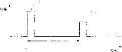
图5A到5C是表示由本发明第一实施例中的障碍检测部分发送或接收的示例性发送信号和接收信号的示意图;5A to 5C are diagrams showing exemplary transmission signals and reception signals transmitted or received by an obstacle detection section in the first embodiment of the present invention;
图6是表示本发明第一实施例中的图3中子程序S107的操作的流程图;Fig. 6 is a flowchart showing the operation of subroutine S107 in Fig. 3 in the first embodiment of the present invention;
图7是用于说明在本发明第一实施例中当障碍图像生成部分生成障碍图像时的操作的简图;FIG. 7 is a diagram for explaining operations when an obstacle image generating section generates an obstacle image in the first embodiment of the present invention;
图8是表示本发明第一实施例中的图3中子程序S108的操作的流程图;Fig. 8 is a flowchart showing the operation of subroutine S108 in Fig. 3 in the first embodiment of the present invention;
图9A和9B是表示在本发明第一实施例中的显示部分上显示的示例性障碍图像的示意图;9A and 9B are diagrams showing exemplary obstacle images displayed on the display section in the first embodiment of the present invention;
图10A和10B是表示在本发明第一实施例中的显示部分上显示的其它示例性障碍图像的示意图;10A and 10B are diagrams showing other exemplary obstacle images displayed on the display section in the first embodiment of the present invention;
图11是表示本发明第二实施例中的图3中子程序S107的操作的流程图;Fig. 11 is a flowchart showing the operation of subroutine S107 in Fig. 3 in the second embodiment of the present invention;
图12A和12B是表示在本发明第二实施例中的显示部分上显示的示例性障碍图像的示意图;12A and 12B are diagrams showing exemplary obstacle images displayed on the display portion in the second embodiment of the present invention;
图13A和13B是表示在本发明第二实施例中的显示部分上显示的其它示例性障碍图像的示意图;13A and 13B are diagrams showing other exemplary obstacle images displayed on the display portion in the second embodiment of the present invention;
图14是表示本发明第三实施例中的图3中子程序S107的操作的流程图;Fig. 14 is a flowchart showing the operation of subroutine S107 in Fig. 3 in the third embodiment of the present invention;
图15是用于说明在本发明第三实施例中当障碍图像生成部分生成障碍图像时的操作的简图;FIG. 15 is a diagram for explaining operations when an obstacle image generating section generates an obstacle image in the third embodiment of the present invention;
图16A和16B是表示在本发明第三实施例中的显示部分上显示的示例性障碍图像的示意图;16A and 16B are diagrams showing exemplary obstacle images displayed on the display section in the third embodiment of the present invention;
图17A和17B是表示在本发明第三实施例中的显示部分上显示的其它示例性障碍图像的示意图;17A and 17B are diagrams showing other exemplary obstacle images displayed on the display section in the third embodiment of the present invention;
图18是表示本发明第四实施例中的图3中子程序S107的操作的流程图;Fig. 18 is a flowchart showing the operation of subroutine S107 in Fig. 3 in the fourth embodiment of the present invention;
图19A和19B是表示在本发明第四实施例中的显示部分上显示的示例性障碍图像的示意图;19A and 19B are diagrams showing exemplary obstacle images displayed on the display section in the fourth embodiment of the present invention;
图20A和20B是表示在本发明第四实施例中的显示部分上显示的其它示例性障碍图像的示意图;20A and 20B are diagrams showing other exemplary obstacle images displayed on the display section in the fourth embodiment of the present invention;
图21是表示根据本发明第五实施例的障碍检测设备的结构的框图;21 is a block diagram showing the structure of an obstacle detection device according to a fifth embodiment of the present invention;
图22是表示当根据本发明第五实施例的障碍检测设备设定形状数据时的操作的流程图;FIG. 22 is a flowchart showing the operation when the obstacle detection apparatus according to the fifth embodiment of the present invention sets shape data;
图23是在本发明第五实施例中的显示部分上显示的示例性形状数据编号设定屏幕;Fig. 23 is an exemplary shape data number setting screen displayed on the display section in the fifth embodiment of the present invention;
图24A和24B是表示在本发明第五实施例中的显示部分上显示的示例性停车位类型选择屏幕和示例性停车位测量设定屏幕的示意图;24A and 24B are diagrams showing an exemplary parking space type selection screen and an exemplary parking space measurement setting screen displayed on the display section in the fifth embodiment of the present invention;
图25A到25H是表示在本发明第五实施例中当输入形状数据时选择的示例性停车位类型的示意图;25A to 25H are diagrams showing exemplary types of parking spaces selected when shape data is input in a fifth embodiment of the present invention;
图26时表示在本发明第五实施例中所存储的作为形状数据的形状点和形状矢量的简图;FIG. 26 is a schematic diagram showing shape points and shape vectors stored as shape data in the fifth embodiment of the present invention;
图27是表示根据本发明第五实施例的障碍检测设备的操作的流程图;27 is a flowchart showing the operation of the obstacle detection device according to the fifth embodiment of the present invention;
图28是表示本发明第四实施例中的图27中子程序S707的操作的流程图;Fig. 28 is a flowchart showing the operation of subroutine S707 in Fig. 27 in the fourth embodiment of the present invention;
图29是表示本发明第五实施例中的障碍检测点的简图;Fig. 29 is a schematic diagram showing obstacle detection points in a fifth embodiment of the present invention;
图30是表示本发明第五实施例中的障碍检测点和内插点的示意图;Fig. 30 is a schematic diagram showing obstacle detection points and interpolation points in the fifth embodiment of the present invention;
图31A和31B是表示本发明第五实施例中的示例性形状矢量和障碍矢量的示意图;31A and 31B are diagrams showing exemplary shape vectors and obstacle vectors in a fifth embodiment of the present invention;
图32A到32D是表示在本发明第五实施例中被引起旋转的示例性形状矢量的示意图;32A to 32D are diagrams showing exemplary shape vectors caused to be rotated in a fifth embodiment of the present invention;
图33是表示在本发明第五实施例中检测到的示例性最佳重合方向形状点的简图;Fig. 33 is a diagram showing exemplary best coincidence direction shape points detected in the fifth embodiment of the present invention;
图34是表示本发明第五实施例中显示部分上显示的示例性障碍图像的简图。Fig. 34 is a diagram showing an exemplary obstacle image displayed on the display section in the fifth embodiment of the present invention.
具体实施方式Detailed ways
第一实施例first embodiment
图1是表示根据本发明第一实施例的障碍检测设备结构的框图。在图1中,该障碍检测设备典型地安装在车辆上,并且其包括障碍检测部分11、距离计算部分12、控制部分13、障碍图像生成部分14、显示部分15和输入部分16。FIG. 1 is a block diagram showing the configuration of an obstacle detection device according to a first embodiment of the present invention. In FIG. 1 , the obstacle detection device is typically mounted on a vehicle, and it includes an obstacle detection section 11 , a distance calculation section 12 , a control section 13 , an obstacle image generation section 14 , a display section 15 and an
该障碍检测部分11构成为无线电波雷达设备,该雷达设备检测车辆附近的障碍。根据将要检测的障碍所在的方向,将该障碍检测部分11安装到从例如该车辆的前、侧和后部选出的一个或多个位置上。障碍检测部分11以预定的发散角多次发射光束,同时改变方向。每次该障碍检测部分11发射光束,其接收位于光束照射范围内的障碍反射的光束反射波。尽管本实施例假定该障碍检测部分1是无线电波雷达,但不限于无线电波雷达,也可以是例如超声波雷达或者激光雷达。The obstacle detection section 11 is constituted as a radio wave radar device that detects obstacles in the vicinity of the vehicle. The obstacle detection section 11 is installed at one or more positions selected from, for example, the front, side, and rear of the vehicle according to the direction in which an obstacle to be detected is located. The obstacle detection section 11 emits the light beam at a predetermined divergence angle multiple times while changing directions. Every time the obstacle detection section 11 emits a light beam, it receives a light beam reflection wave reflected by an obstacle located within the beam irradiation range. Although the present embodiment assumes that the
障碍检测部分11包括发送部分111、接收部分112和天线113。发送部分111生成发送信号,并且除了向天线113输出发送信号之外,还向距离计算部分12输出部分发送信号。天线113发射具有预定发散角的光束并且接收障碍反射的光束反射波的接收信号。接收部分112输出由天线113接收到的接收信号,该接收部分112包括放大器、检测器等等。The obstacle detection section 11 includes a transmission section 111 , a reception section 112 and an
天线113是例如天线阵列。天线阵列由设置在相同平面中的多个天线单元和相同数量的移相器构成,该移相器用于分别向与其相对应的天线单元提供发送信号,该天线阵列控制从每个移相器提供给与其相对应的天线单元的信号的振幅和相位,从而在需要的方向上发射光束。注意天线113可以包括分立的天线单元,即用于发送的天线单元和用于接收的天线单元。可选择的是,可以将双工机、循环器等用来将同一个天线单元应用于发送和接收。The
接着,参照图2,更加具体地描述了障碍检测部分11发射的光束。在图2中,表示了障碍检测部分11发射的光束。在图2中,障碍检测部分11的天线113安装在车辆V的后部中心处。天线113在线段LS表示的方向上发射光束BM,该线段与车辆中心线CL(参见虚线)成预定角θ。在以线段LS为中心的预定角度范围α内发射光束BM。Next, referring to FIG. 2 , the light beam emitted by the obstacle detection section 11 will be described more specifically. In FIG. 2, the light beam emitted by the obstacle detection section 11 is shown. In FIG. 2 , the
在本实施例中,发射的光束所在方向由从天线113观察到的光束与车辆中心线CL所成夹角表示,其中假定车辆中心线CL表示0°,车辆左侧对应于负侧,车辆右侧对应于正侧。例如,图2中线段LS表示的方向为-θ。障碍检测部分11多次发射光束BM,同时改变方向,从而在预定角度范围内发射光束。In this embodiment, the direction of the emitted light beam is indicated by the angle formed by the light beam observed from the
根据从发送部分111输出的发送信号和从接收部分112输出的接收信号,距离计算部分12计算从天线113到障碍的距离,并且将其作为距离数据输出。控制部分13向发送部分111输出方向数据,该方向数据表示将要发射光束的方向,并且在根据该方向数据发射了光束之后,该控制部分存储从距离计算部分12输出的距离数据以及方向数据。Based on the transmission signal output from transmission section 111 and the reception signal output from reception section 112, distance calculation section 12 calculates the distance from
根据存储在控制部分13中的方向数据和距离数据,障碍图像生成部分14生成障碍图像,该图像至少表示检测到的障碍的位置。显示部分15是例如设置在车辆控制台中的诸如LCD的显示器,其显示由障碍图像生成部分14生成的障碍图像。输入部分16例如用于改变障碍检测设备的开/关,其是例如司机操作的选择器开关或者键盘。Based on the direction data and the distance data stored in the control section 13, the obstacle image generating section 14 generates an obstacle image showing at least the position of the detected obstacle. The display section 15 is, for example, a display such as an LCD provided in a vehicle console, and displays the obstacle image generated by the obstacle image generation section 14 . The
接着,参照图3,描述了本障碍检测设备的操作。图3是表示整个本障碍检测设备操作的流程图。一旦本障碍检测设备开始扫描车辆的周围区域,该控制部分13就向发送部分111输出表示将要发射光束的方向的方向数据,而且还增加表示已经发射光束次数的计数(步骤S101)。Next, referring to FIG. 3 , the operation of the present obstacle detection device is described. Fig. 3 is a flow chart showing the operation of the entire obstacle detection device. Once the present obstacle detection device starts scanning the surrounding area of the vehicle, the control section 13 outputs direction data indicating the direction in which the beam will be emitted to the transmitting section 111, and also increments a count indicating the number of times the beam has been emitted (step S101).
一旦从控制部分13输出方向数据,发送部分111就向天线113输出发送信号和方向控制信号,用于在由方向数据表示的方向上发射光束,由此其发射光束。此外,发送部分111向距离计算部分12输出发送信号(步骤S102)。接收部分112在步骤S302发射的光束的反射波,并且将接收信号输出到距离计算部分12(步骤S103)。Upon outputting the direction data from the control section 13, the transmission section 111 outputs a transmission signal and a direction control signal to the
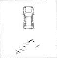
接着,参照图4和5分别具体描述了该障碍检测设备在步骤S102和S103的操作。图4是从车辆上方观察到的表示车辆V开始倒车以停到停车位PL中的简图。障碍SC是围绕停车位PL三面的结构。在车辆V的后部,安装了障碍检测部分11的天线113。当从车辆上方观察时,天线113发射的光束BM的光束发散角约为16°。每次发射时,发射光束BM的方向偏移大约6°,并且在一次扫描中发射十次。Next, the operations of the obstacle detection device in steps S102 and S103 are specifically described with reference to FIGS. 4 and 5 , respectively. FIG. 4 is a diagram showing a vehicle V starting to reverse into a parking space PL, viewed from above the vehicle. The obstacle SC is a structure surrounding the parking space PL on three sides. At the rear of the vehicle V, an
天线113发射的单一光束BM传播的同时在两条虚线DL之间的范围内展开,并照射到粗线表示的墙壁表面WL上。该墙壁表面WL反射光束BM,接收部分112接收接收信号,该信号是来自墙壁表面WL上各个点的反射波的集合。The single beam BM emitted by the
接着,根据发送信号和接收信号,距离计算部分12计算从天线到障碍的距离(步骤S104)。参照图5A和5B,具体描述了当计算从天线113到障碍的距离时该距离计算部分12的操作。在图5A和5B的各图中,表示了作为发送信号PB1的脉冲光束,此外,由障碍SC反射的发送信号PB1的反射波表示为接收信号PB2。Next, based on the transmission signal and the reception signal, the distance calculation section 12 calculates the distance from the antenna to the obstacle (step S104). Referring to FIGS. 5A and 5B , the operation of the distance calculation section 12 when calculating the distance from the
图5A表示了理想的接收信号PB2,其与发送信号PB1具有同样清晰的矩形形状。时间量τ为天线113发射发送信号PB1的时刻T0与天线113接收接收信号PB2的时刻T1之差,该时间量对应于光束及其反射波(即无线电波)从天线113传播到障碍SC并反向传播回去所占用的时间长度。这里,天线113和障碍SC之间的距离D由以下公式(1)给出。FIG. 5A shows an ideal received signal PB2 which has the same clear rectangular shape as the transmitted signal PB1 . The amount of time τ is the difference between the moment T0 when the
在以上公式(1)中,c表示光速。然而,实际上如图4所示,如果从障碍SC上光束照射的各点到天线113的距离不同,则由该障碍SC上不同点处的反射生成的反射波到达天线所占用的时间长度不同。因此,接收信号变为在时间上是波动、分散的。而且,接收部分112不仅接收反射波还接收噪声。因此,接收信号的形状与如图5B所示的具有畸变波形的接收信号PB3的形状相似,而不是清晰的矩形形状。利用该接收信号PB3,难以确定时间量τ,因此难以精确地计算距离D。In the above formula (1), c represents the speed of light. However, as shown in FIG. 4, if the distances from the points on the obstacle SC to which the light beams are irradiated are different from the
然后,为了将接收信号与噪声区分开,为反射波的振幅设定了预定阈值,并且距离计算部分12计算在接收信号的振幅大于阈值的时段期间的平均值。更具体地讲,距离计算部分12检测接收信号PB3超过阈值的时间T2以及接收信号PB3的振幅随后下降到阈值以下的时间T3,从而获得时间量τ,该时间量为时间T2和时间T3的平均值与时间T0之差。根据由此获得的时间量τ,利用前述的公式(1)计算天线113与检测到的障碍SC之间的距离。Then, in order to distinguish the received signal from noise, a predetermined threshold is set for the amplitude of the reflected wave, and the distance calculation section 12 calculates an average value during a period in which the amplitude of the received signal is larger than the threshold. More specifically, the distance calculation section 12 detects the time T2 when the received signal PB3 exceeds the threshold value and the time T3whenthe amplitude of the received signalPB3 subsequently falls below the threshold value, thereby obtaining the amount of time τ, which is the timeT2 and the difference between the mean value at timeT3 and timeT0 . From the amount of time τ thus obtained, the distance between the
同样参照图4,具体地解释如上所述的利用距离计算部分12算得的从天线113到障碍SC的距离。因为天线113发射的光束BM在位于其照射范围内的墙壁表面WL上无数个点处反射,所以该墙壁表面上从最接近天线113的点到最远离天线113的点范围内的多个点反射的反射波被一起接收到。根据这样的反射波的接收信号如上所述算得的距离D,对应于从天线113到墙壁表面WL上最接近点的距离与从天线113到墙壁表面WL上最远离点的距离的平均值。图4示出的弧RC表示利用落入光束BM的照射角度范围内的弧按照上述方式算得的距离D,该弧在以天线113为中心的、半径等于按照上述方式算得的距离D的圆周外。Referring also to FIG. 4 , the distance from the
因此,通过计算在发射光束BM的每个方向上到障碍SC的距离,就检测到车辆附近存在的障碍SC的位置。这里,光束的发散角越小,测得的障碍SC所在的角度范围RC越有限,因此能够更加精确地确定障碍SC的位置。另一方面,光束BM的发散角越大,障碍SC的位置检测越粗略。而且,假定光束BM的发散角相同,则当从天线113到障碍SC的距离变小时,光束BM的照射范围变小。因此,从天线113到障碍SC的距离越小,就能够更加精确地检测障碍SC的位置。另一方面,从天线113到障碍SC的距离越大,障碍SC的位置检测越粗略。Therefore, by calculating the distance to the obstacle SC in each direction of the emitted light beam BM, the position of the obstacle SC existing near the vehicle is detected. Here, the smaller the divergence angle of the light beam is, the more limited the angle range RC where the obstacle SC is measured is, so the position of the obstacle SC can be determined more accurately. On the other hand, the larger the divergence angle of the light beam BM, the rougher the position detection of the obstacle SC. Also, assuming that the divergence angle of the light beam BM is the same, as the distance from the
注意,需要预先设定用于检测接收信号的阈值。然而,在车辆的实际行驶过程中,任何物体都可以成为障碍SC,并且无线电波的反射率随物体的材料和形状而改变。因此,实际上优选的是在某种程度上预先识别所要检测的作为障碍SC的物体,并且将能够检测各物体中反射率最低的物体的振幅值设定为阈值。Note that a threshold for detecting a received signal needs to be set in advance. However, any object can become an obstacle SC during actual running of the vehicle, and the reflectance of radio waves varies with the material and shape of the object. Therefore, it is actually preferable to recognize in advance the object to be detected as the obstacle SC to some extent, and to set an amplitude value capable of detecting the object with the lowest reflectance among the objects as the threshold value.
接着,控制部分13存储表示已经发射了光束的方向的方向数据以及通过距离计算部分12的计算获得的距离数据(步骤S105)。控制部分13根据发射光束的次数是否已经达到在一次扫描中所要发射光束的预定次数(在本实施例中假定为10次)来确定是否已经完成扫描(步骤S106)。如果控制部分13确定还未完成扫描,则控制返回步骤S101,并且继续扫描。另一方面,如果确定了已经完成扫描,则控制部分13前进到步骤S107。Next, the control section 13 stores direction data indicating the direction in which the light beam has been emitted, and distance data obtained by calculation by the distance calculation section 12 (step S105). The control section 13 determines whether scanning has been completed based on whether the number of times of emitting beams has reached a predetermined number of times (assumed to be 10 times in this embodiment) to be emitted in one scan (step S106). If the control section 13 determines that scanning has not been completed, control returns to step S101, and scanning is continued. On the other hand, if it is determined that scanning has been completed, the control section 13 proceeds to step S107.
障碍图像生成部分14根据存储在控制部分13中的方向数据和距离数据,生成用于显示障碍位置的障碍图像(步骤S107)。The obstacle image generation section 14 generates an obstacle image for displaying the location of the obstacle based on the direction data and the distance data stored in the control section 13 (step S107).
接着,参照图6和图7,具体描述了步骤S107中障碍图像生成部分14的操作。图6是表示在步骤S107中障碍图像生成部分14实施的子程序过程的流程图。在图7中表示了在步骤S107中生成的障碍图像。该障碍图像生成部分14首先绘制投影车辆图像IV,该图像为从上方的车辆投影(步骤S201)。这时,定义坐标,其原点设定在投影车辆图像IV的天线位置PAT,其中该位置PAT的设定位置在与天线113安装到真实车辆上的位置相同。Next, referring to FIG. 6 and FIG. 7 , the operation of the obstacle image generating section 14 in step S107 is specifically described. FIG. 6 is a flowchart showing the subroutine procedure executed by the obstacle image generating section 14 in step S107. The obstacle image generated in step S107 is shown in FIG. 7 . The obstacle image generation section 14 first draws a projected vehicle imageIV which is projected from the vehicle above (step S201). At this time, coordinates are defined whose origin is set at the antenna position PAT of the projected vehicle imageIV , where the set position of the position PAT is the same as the position where the
接着,障碍图像生成部分14根据存储在控制部分13中的10组方向数据和距离数据中的每一组绘制至少一条“障碍存在线”LSC(步骤S202)。障碍存在线LSC是本实施例中的示例性障碍图像,其对应于例如图4所示的弧RC,并且表示了在每一个发射光束BM照射方向测得的障碍位置。更具体地讲,对于每个方向数据以及与其相对应的距离数据,障碍图像生成部分14绘制了以天线位置PAT为中心(即原点)的弧,其中距离数据定义了其半径,并且该弧在大约16°的角度范围上延伸,且具有由方向数据表示的中心线方向。例如,图7中表示的障碍存在位置线LSC是在方向数据为θ1并且距离数据为D1的情况下的障碍存在线。在上述的步骤S202之后,该过程前进到下一子程序步骤S108(参见图3)。Next, the obstacle image generation section 14 draws at least one "obstacle presence line" LSC based on each of the 10 sets of direction data and distance data stored in the control section 13 (step S202). The obstacle existence line LSC is an exemplary obstacle image in this embodiment, which corresponds to, for example, the arc RC shown in FIG. 4 , and indicates the obstacle position measured in each irradiation direction of the emitted light beam BM. More specifically, for each direction data and its corresponding distance data, the obstacle image generation section 14 draws an arc centered at the antenna position PAT (ie, the origin), where the distance data defines its radius, and the arc Extends over an angular range of approximately 16° and has a centerline orientation represented by orientation data. For example, the obstacle existence position line LSC shown in FIG. 7 is an obstacle existence line in the case where the direction data isθ1 and the distance data isD1 . After the above-mentioned step S202, the process proceeds to the next subroutine step S108 (see FIG. 3).
在步骤S108,障碍图像生成部分14绘制表示测得的障碍形状的线段。图8是表示步骤S108的子程序过程的流程图。根据方向数据以及距离数据,障碍图像生成部分14计算表示测得的障碍位置的点(下文中称作“障碍检测点”)PSC的坐标(步骤S301)。例如,图7中表示的点PSC是在方向数据和距离数据分别为θ1和D1的情况下的障碍的障碍检测点。在这种情况下,点PSC的坐标是(x,y)=(D1sinθ1,D1cosθ1)。障碍图像生成部分14绘制了折线CL,该折线一个接一个地连接了在步骤S301算得的障碍检测点PSC的坐标(步骤S302)。在上述步骤S302的过程之后,障碍检测设备的操作返回图3所示的主程序。In step S108, the obstacle image generating section 14 draws a line segment representing the measured shape of the obstacle. FIG. 8 is a flowchart showing the subroutine procedure of step S108. Based on the direction data and the distance data, the obstacle image generation section 14 calculates the coordinates of a point (hereinafter referred to as "obstacle detection point") PSC representing the measured obstacle position (step S301 ). For example, the point PSC shown in FIG. 7 is an obstacle detection point of an obstacle when the direction data and the distance data areθ1 andD1, respectively. In this case, the coordinates of the point PSC are (x, y)=(D1 sinθ1 , D1 cosθ1 ). The obstacle image generation section 14 draws a polyline CL connecting the coordinates of the obstacle detection points PSC calculated in step S301 one by one (step S302 ). After the process of step S302 described above, the operation of the obstacle detection device returns to the main routine shown in FIG. 3 .
再次参照图3,显示部分15为司机显示在步骤S107由障碍图像生成部分14生成的障碍图像(步骤S109)。控制部分13确定障碍检测设备系统是否打开(步骤S110)。例如,利用设置在输入部分16中的选择器开关,通过司机的操作输入障碍检测设备系统的开/关。如果以上确定为是,则控制部分13将已经发射光束的次数的计数器复位(步骤S111),该过程返回步骤S101,然后开始再次扫描障碍。另一方面,如果以上确定为否,则结束该障碍检测设备的操作。Referring again to FIG. 3, the display section 15 displays the obstacle image generated by the obstacle image generation section 14 in step S107 for the driver (step S109). The control section 13 determines whether the obstacle detection device system is turned on (step S110). For example, with a selector switch provided in the
图9A和9B以及图10A和10B表示了在图4所示的车辆V移动到停车位PL中之前各个阶段的障碍图像。在各个附图中,尽管出于相互比较的目的,将对应于实际障碍外形的线用虚线表示,但应注意在实际的障碍图像中没有画出该虚线。由这些障碍图像清楚地了解到,当与障碍的距离随着车辆移动而变小时,光束的照射范围更加有限,因此障碍存在线(弧)更短并且更加精确地画出障碍的位置。司机参照连接了障碍存在线LSC中点的折线CL来了解障碍的形状。在每个附图中,为了方便,仅为一条障碍存在线附加了附图标记“LSC”。9A and 9B and FIGS. 10A and 10B show obstacle images at various stages before the vehicle V shown in FIG. 4 moves into the parking space PL. In the respective drawings, although the line corresponding to the outline of the actual obstacle is indicated by a dotted line for the purpose of mutual comparison, it should be noted that the dotted line is not drawn in the actual obstacle image. It is clear from these obstacle images that when the distance to the obstacle becomes smaller as the vehicle moves, the beam's irradiation range is more limited, so the obstacle presence line (arc) is shorter and the obstacle's position is drawn more accurately. The driver knows the shape of the obstacle by referring to the broken line CL connecting the middle points of the obstacle presence lineLSC . In each drawing, only one obstacle existence line is appended with reference numeral "LSC " for convenience.
如上所述,本障碍检测设备绘制了障碍存在线LSC,其表示以在光束照射范围内与车辆的距离为根据的障碍位置,从而显示了很可能出现障碍的范围。而且,本障碍检测设备绘制了连接各点的线段,每个点表示对于每个光束的照射角度范围测得的代表性障碍位置,从而显示障碍形状。即使在使用了光束发散角较大的雷达的情况下,这能使司机轻易地掌握车辆附近的障碍位置和形状。As described above, the present obstacle detection device draws the obstacle existence line LSC representing the obstacle position based on the distance from the vehicle within the beam irradiation range, thereby showing the range where the obstacle is likely to occur. Also, the present obstacle detection device draws a line segment connecting points each representing a representative obstacle position measured for the irradiation angle range of each light beam, thereby showing the shape of the obstacle. This enables the driver to easily grasp the position and shape of obstacles near the vehicle even when using a radar with a large beam divergence.
在本实施例中,距离计算部分12通过将在接收信号的振幅大于预定阈值的时段中的平均值与发射光束的时间之差当作时间量τ来计算与障碍的距离。可选择的是,如图5C所示,可以通过将在接收信号的振幅首次超过预定阈值时的时间T2与根据发送信号发射光束时的时间T0之差当作时间量τ来计算与障碍的距离。按照这种方式算得的距离是,位于每个光束的照射范围内存在的任何(多个)障碍中到离所述车辆最近的障碍的距离,并且在障碍图像中绘制的障碍存在线表示最接近车辆的位置,在该位置可能存在在每个光束的照射范围内测得的障碍。因此,司机能够通过实施驾驶操作使得障碍图像中的投影车辆图像IV不会与障碍存在线LSC相接触,来避免车辆与障碍接触。In the present embodiment, the distance calculation section 12 calculates the distance to the obstacle by taking the difference between the average value in the period in which the amplitude of the received signal is larger than a predetermined threshold and the time at which the light beam is emitted, as the time amount τ. Alternatively, as shown in FIG. 5C ,the difference between the time T when the amplitude of the received signal first exceeds a predetermined threshold and the time T when the light beam is emitted according to the transmitted signal can be used as the time amountτ to calculate the difference with the barrier distance. The distance calculated in this way is the distance from any obstacle(s) existing within the irradiation range of each beam to the obstacle closest to the vehicle, and the obstacle presence line drawn in the obstacle image represents the closest The position of the vehicle where there may be obstacles measured within the range of each beam. Therefore, the driver can prevent the vehicle from coming into contact with the obstacle by performing a driving operation so that the projected vehicle imageIV in the obstacle image does not come into contact with the obstacle presence line LSC .
此外,已经假设在本障碍检测设备的障碍检测部分11中使用天线阵列以通过电子方法改变发射光束的方向。然而,也可以通过改变在一个预定方向上发射光束的天线方向来借助机械方法改变发射光束的方向。Furthermore, it has been assumed that an antenna array is used in the obstacle detection section 11 of the present obstacle detection device to electronically change the direction of the emitted light beam. However, it is also possible to change the direction of the emitted light beam mechanically by changing the direction of the antenna which emits the light beam in a predetermined direction.
第二实施例second embodiment
下面,描述了根据本发明第二实施例的障碍检测设备。根据本发明的障碍检测设备的特征在于,当从雷达到障碍的距离变小时,以更粗的线画出障碍图像中的障碍存在线。因为这个特征,包含在本障碍检测设备中的障碍图像生成部分14实施不同于上述第一实施例的处理。Next, an obstacle detection device according to a second embodiment of the present invention is described. The obstacle detection device according to the present invention is characterized in that the obstacle presence line in the obstacle image is drawn with a thicker line as the distance from the radar to the obstacle becomes smaller. Because of this feature, the obstacle image generation section 14 included in the present obstacle detection device implements processing different from that of the first embodiment described above.
接着,参照图11,围绕与第一实施例的差别描述障碍图像生成部分14的操作。图11是表示本障碍图像生成部分14的操作的流程图。图11的流程图与根据第一实施例的流程图(参见图6)基本相同,不同之处在于步骤S102的处理被步骤S403取代,并且添加了步骤S402的处理。因此,在图11所示的步骤中,省略了对于与图3相同的任何步骤的描述。Next, referring to FIG. 11 , the operation of the obstacle image generating section 14 will be described around differences from the first embodiment. FIG. 11 is a flowchart showing the operation of the present obstacle image generation section 14 . The flowchart of FIG. 11 is basically the same as the flowchart according to the first embodiment (see FIG. 6 ), except that the processing of step S102 is replaced by step S403 and the processing of step S402 is added. Therefore, among the steps shown in FIG. 11 , the description of any steps that are the same as those in FIG. 3 is omitted.
对于存储在控制部分13中的10个距离数据中的每一个,障碍图像生成部分14从预定数量的级别中确定一个距离级别(步骤S402),该级别逐级地表示与车辆的距离。For each of the 10 pieces of distance data stored in the control section 13, the obstacle image generating section 14 determines a distance level from a predetermined number of levels (step S402), which level represents the distance to the vehicle step by step.
例如,可以按照以下方式确定距离级别。假定距离级别的数量为4个,即按照距离上升顺序的级别1、级别2、级别3和级别4。假定ΔD=(Dmax-Dmin)÷4,其中Dmax和Dmin分别是存储在控制部分13中的10个距离数据中的最大值和最小值,根据满足以下条件表达式(2)到(5)中的哪一个来确定距离数据Di的距离级别。For example, the distance level can be determined as follows. It is assumed that the number of distance levels is 4, that is,
Di≤Dmin+ΔD…(2)Di ≤ Dmin +ΔD...(2)
Dmin+ΔD<Di≤Dmin+2×ΔD…(3)Dmin +ΔD<Di ≤Dmin +2×ΔD...(3)
Dmin+2×ΔD<Di≤Dmin+3×ΔD…(4)Dmin +2×ΔD<Di ≤Dmin +3×ΔD…(4)
Dmin+3×ΔD<Di…(5)Dmin +3×ΔD<Di ...(5)
这里,如果距离数据Di满足表达式(2),则其距离级别确定为级别1。如果其满足表达式(3),则距离级别确定为级别2。如果其满足表达式(4),则距离级别确定为级别3。如果其满足表达式(5),则距离级别确定为级别4。Here, if the distance data Di satisfies Expression (2), its distance level is determined to be
障碍图像生成部分14根据方向数据以及距离数据按照与第一实施例基本相同的方式绘制障碍存在线,不同之处在于根据在步骤S402为每个距离数据确定的距离级别来改变线的粗度(步骤S403)。例如,将为各距离级别,即级别1、级别2、级别3和级别4绘制的线的粗度预先分别确定为1.0mm、0.7mm、0.4mm和0.2mm,并且障碍图像生成部分14绘制粗度对应于其各自距离级别的障碍存在线。The obstacle image generation section 14 draws an obstacle existence line based on the direction data and the distance data in substantially the same manner as in the first embodiment, except that the thickness of the line is changed in accordance with the distance level determined for each distance data in step S402 ( Step S403). For example, the thicknesses of the lines drawn for the respective distance levels, that is,
图12A和12B以及图13A和13B表示了本障碍图像生成部分14生成的障碍图像。在各个附图中,尽管出于相互比较的目的,用虚线表示了对应于实际障碍外形的线,但应注意在实际的障碍图像中没有画出该虚线。与第一实施例中的障碍图像相比,这些障碍图像的特征在于以逐渐变粗的线绘制了与车辆距离较近的障碍的障碍存在位置线。根据这些附图可以了解到,修改距离车辆较近的那些障碍存在线LSC,使得这些障碍存在线(弧)的粗度逐渐变大,由此更加突出所显示的障碍存在线LSC。12A and 12B and FIGS. 13A and 13B show obstacle images generated by the present obstacle image generating section 14 . In the respective drawings, although the line corresponding to the outline of the actual obstacle is indicated by a dotted line for the purpose of mutual comparison, it should be noted that the dotted line is not drawn in the actual obstacle image. Compared with the obstacle images in the first embodiment, these obstacle images are characterized in that the obstacle existence position lines of the obstacles closer to the vehicle are drawn in gradually thicker lines. According to these drawings, it can be understood that those obstacle presence lines LSC that are closer to the vehicle are modified so that the thickness of these obstacle presence lines (arcs) gradually becomes larger, thereby making the displayed obstacle presence lines LSC more prominent.
在第一实施例中,在障碍图像中以相同粗度绘制了所有障碍存在线。比较起来,当其与车辆的距离变小时,本障碍检测设备以更粗的线绘制了障碍存在线LSC。换句话说,当其与车辆的距离变小时,更加突出地绘制出表示障碍位置的障碍存在线LSC。因此,易于司机掌握需要更加注意的障碍位置。In the first embodiment, all obstacle presence lines are drawn with the same thickness in the obstacle image. In comparison, the present obstacle detection device draws the obstacle presence line LSC with a thicker line as its distance from the vehicle becomes smaller. In other words, the obstacle existence line LSC representing the obstacle position is drawn more prominently as its distance from the vehicle becomes smaller. Therefore, it is easy for the driver to grasp the position of an obstacle requiring more attention.
此外,在本实施例中,已经假定了障碍检测设备检测该接收信号的振幅大于某个阈值的时段的开始时间和终止时间,并且确定了根据这两个时间中间的时间算得的距离,作为障碍与车辆之间的代表性距离;或者假定障碍检测设备检测该接收信号的振幅大于某个阈值的时段的开始时间,并且确定了根据该开始时间算得的距离,作为障碍与车辆之间的代表性距离。然而,计算代表性距离的方式不限于上述的方式,还可以使用例如所谓的欠采样(under-sampling)方法。该欠采样方法是用于检测接收信号的方法,该方法基于多个脉冲重复周期的持续时间与车辆和障碍之间的相对速度相比足够微小的假设,以及在该持续时间内车辆和障碍之间的距离保持不变的假设。检查发送信号的副本和接收信号之间的相关性,同时每次移动时将接收信号移动一微小时间。当根据相关波形的高振幅而确定存在相关性时,如果获知了关于接收信号已经移动的微小时间的信息,则障碍检测设备将根据该信息算得的距离确定为障碍与车辆之间的代表性距离。Furthermore, in this embodiment, it has been assumed that the obstacle detection device detects the start time and end time of the period in which the amplitude of the received signal is greater than a certain threshold, and determines the distance calculated from the time between these two times as the obstacle The representative distance from the vehicle; or assuming that the obstacle detection device detects the start time of the period in which the amplitude of the received signal is greater than a certain threshold, and determines the distance calculated from the start time as a representative distance between the obstacle and the vehicle distance. However, the way of calculating the representative distance is not limited to the above-mentioned way, and it is also possible to use, for example, a so-called under-sampling method. This undersampling method is a method for detecting received signals based on the assumption that the duration of multiple pulse repetition periods is sufficiently small compared to the relative speed between the vehicle and the obstacle, and that the distance between the vehicle and the obstacle is Assume that the distance between them remains constant. Check the correlation between a copy of the sent signal and the received signal, while shifting the received signal by a tiny amount of time each shift. When it is determined that there is a correlation based on the high amplitude of the correlation waveform, if information about the minute time that the received signal has moved is known, the obstacle detection device determines the distance calculated from the information as a representative distance between the obstacle and the vehicle .
这种方法不需要高速A/D转换器,从而可以借助较简单的硬件配置来计算代表性距离,该高速A/D转换器对于本实施例中描述的代表性距离的计算是必要的。This method does not require a high-speed A/D converter, which is necessary for the calculation of the representative distance described in this embodiment, to calculate the representative distance with a simpler hardware configuration.
注意,在本实施例中已经假定了根据与车辆的距离,改变车辆障碍存在线LSC的粗度。可选择的是,其可以设置成改变障碍存在线LSC的颜色。和障碍存在线LSC的粗度改变的情况一样,这可以使障碍检测设备显示障碍存在线LSC,使得当其与车辆的距离变小时看上去更为突出。Note that it has been assumed in the present embodiment that the thickness of the vehicle obstacle presence line LSC is changed in accordance with the distance from the vehicle. Alternatively, it may be set to change the color of the obstacle presence line LSC . As in the case where the thickness of the obstacle presence line LSC is changed, this enables the obstacle detection device to display the obstacle presence line LSC so that it looks more prominent as the distance from the vehicle becomes smaller.
第三实施例third embodiment
接着,描述根据本发明第三实施例的障碍检测设备。根据第二实施例的障碍检测设备以弧表示了测得的障碍位置,该弧的线的粗度根据与车辆的距离而改变。比较而言,本障碍检测设备的特征在于测得的障碍位置由具有一定面积的图形(下文中称作“障碍存在区域”)ASC表示,并且该图形的亮度根据与车辆的距离而变化。因为这个特征,包含在本障碍检测设备中的障碍图像生成部分14实施与上述第二实施例不同的处理。Next, an obstacle detection device according to a third embodiment of the present invention is described. The obstacle detection device according to the second embodiment represents the measured obstacle position as an arc whose line thickness changes according to the distance from the vehicle. In comparison, the present obstacle detection device is characterized in that the measured obstacle position is represented by a figure having a certain area (hereinafter referred to as "obstacle presence area")ASC , and the brightness of the figure changes according to the distance from the vehicle. Because of this feature, the obstacle image generation section 14 included in the present obstacle detection device implements different processing from the second embodiment described above.
接着,参照图14,关于与第二实施例的差别描述障碍图像生成部分14实施的处理。图14是表示本障碍图像生成部分14的操作的流程图。图14所示的流程图与根据第二实施例的流程图(参见图11)基本相同,不同之处在于步骤S403的处理被步骤S503和步骤S504的处理取代。因此,在图14所示的步骤中,省略了对于与图11中相同的步骤的说明。Next, referring to FIG. 14 , the processing performed by the obstacle image generation section 14 will be described regarding differences from the second embodiment. FIG. 14 is a flowchart showing the operation of the present obstacle image generation section 14 . The flowchart shown in FIG. 14 is basically the same as the flowchart according to the second embodiment (see FIG. 11 ), except that the processing of step S403 is replaced by the processing of steps S503 and S504. Therefore, in the steps shown in FIG. 14 , explanations for the same steps as those in FIG. 11 are omitted.
障碍图像生成部分14根据方向数据和距离数据绘制障碍存在区域ASC(步骤S503)。以下参照图15具体描述在步骤S503时,该障碍图像生成部分14实施的操作。图15表示了在步骤S503绘制的障碍存在区域ASC。图15所示的障碍存在区域ASC是根据方向数据θ1和距离数据D1绘制的,并且该区域是椭圆形的,其长轴对应于在该方向上发射的光束的照射范围。图15所示的点H是天线的位置,点I和点J分别是椭圆形障碍存在区域ASC的主轴的两个端点,点K是该障碍存在区域ASC的中心。注意该障碍存在区域ASC对应于图7中的障碍存在线LSC,点I和点J与障碍存在线LSC的端点重合。The obstacle image generation section 14 draws the obstacle existence areaASC based on the direction data and the distance data (step S503). The operation performed by the obstacle image generating section 14 at the time of step S503 will be specifically described below with reference to FIG. 15 . FIG. 15 shows the obstacle presence area ASC drawn in step S503. The obstacle existence area ASC shown in FIG. 15 is drawn based on the direction dataθ1 and the distance dataD1 , and the area is elliptical, the major axis of which corresponds to the irradiation range of the light beam emitted in this direction. Point H shown in FIG. 15 is the position of the antenna, point I and point J are the two endpoints of the main axis of the elliptical obstacle existence areaASC , respectively, and point K is the center of the obstacle existence areaASC . Note that this obstacle existence area ASC corresponds to the obstacle existence line LSC in FIG. 7 , and points I and J coincide with the end points of the obstacle existence line LSC .
障碍图像生成部分14根据方向数据和距离数据计算该椭圆形长轴的长度以及该椭圆形中心的坐标。在图15中,该椭圆形的长轴IJ是一条线段,该线段连接了与天线的距离都是D1并且方向彼此相差16°的两个点。因此,该主轴IJ对应于等腰三角形的底边长度,该等腰三角形两条侧边的长度均为D1并且它们形成了大约16°的内角。这里,因为点K是该边IJ的中点,所以三角形△HIK和△HJK均为直角三角形,其斜边的长度为D1并且其内角之一大约为8°。因此,边IK和JK的长度都是D1sin8°,并且所获得的长轴IJ的长度为2D1sin8°。The obstacle image generation section 14 calculates the length of the major axis of the ellipse and the coordinates of the center of the ellipse from the direction data and the distance data. In FIG. 15 , the major axis IJ of the ellipse is a line segment connecting two points that are both at a distance D1 from the antenna and whose directions differ from each other by 16°. This major axis IJ thus corresponds to the length of the base of an isosceles triangle whose two sides are both of lengthD1 and which form an interior angle of approximately 16°. Here, since the point K is the midpoint of the side IJ, the triangles ΔHIK and ΔHJK are both right triangles whose hypotenuse has a lengthD1 and one of its interior angles is about 8°. Therefore, the lengths of both sides IK and JK are D1 sin8°, and the length of the obtained major axis IJ is 2D1 sin8°.
按照以下方式获得该椭圆形中心K的坐标。图15中的三角形△HIK是直角三角形,其斜边HI长度为D1,并且其内角∠IHK约为8°。因此,边HK的长度为D1cos8°。也就是说,因为从天线观察点K的方向是θ1并且其与天线的距离是D1cos8°,所以该椭圆形中心K的坐标表示为(x,y)=(D1cos8°sinθ1,D1cos8°cosθ1)。The coordinates of the center K of this ellipse are obtained in the following manner. The triangle ΔHIK in FIG. 15 is a right triangle whose hypotenuse HI has a length D1 and whose interior angle ∠IHK is about 8°. Therefore, the length of side HK is D1 cos8°. That is, since the direction of point K viewed from the antenna is θ1 and its distance from the antenna is D1 cos8°, the coordinates of the center K of this ellipse are expressed as (x, y)=(D1 cos8° sin θ1 , D1 cos8°cosθ1 ).
障碍存在区域的倾斜度就是由方向数据θ1给定的角度θ1。椭圆形障碍存在区域ASC的短轴长度为预定的固定长度。障碍图像生成部分14根据该椭圆形长轴和短轴的长度、中心坐标以及该椭圆形的倾斜度绘制了各个障碍存在区域ASC,其中该椭圆形长轴和短轴的长度、中心坐标以及该椭圆形的倾斜度是根据方向数据和距离数据按照上述方式获得的。The inclination of the obstacle existing region is the angle θ1 given by the direction data θ1 . The minor axis length of the elliptical obstacle existence areaASC is a predetermined fixed length. The obstacle image generation section 14 draws each obstacle existence area ASC according to the lengths of the major and minor axes of the ellipse, the center coordinates, and the inclination of the ellipse, wherein the lengths of the major and minor axes of the ellipse, the center coordinates, and The inclination of the ellipse is obtained in the above-described manner from the direction data and the distance data.
接着,障碍图像生成部分14填充在步骤S503绘制的各个障碍存在区域ASC的内部,使其亮度变化,从而障碍越接近车辆,其看上去越醒目(步骤S504)。更具体地讲,如第二实施例一样,预先确定对应于在步骤S502确定的各个距离等级的亮度,并且障碍图像生成部分14以对应于相应距离等级的亮度填充各个障碍存在区域ASC的内部。Next, the obstacle image generating section 14 fills the inside of each obstacle existing areaASC drawn in step S503, changing its brightness so that the closer the obstacle is to the vehicle, the more conspicuous it appears (step S504). More specifically, as in the second embodiment, the brightness corresponding to each distance level determined at step S502 is determined in advance, and the obstacle image generation section 14 fills the inside of each obstacle existence area ASC with the brightness corresponding to the corresponding distance level .
图16A和16B以及图17A和17B表示了本障碍图像生成部分14生成的障碍图像。在每个附图中,尽管出于相互比较的目的用虚线表示了对应于实际障碍外形的线,但是注意在实际的障碍图像中未画出该虚线。在这些障碍图像中,利用不同的亮度填充障碍存在区域ASC的内部,使得障碍存在区域ASC与车辆的距离越小,其看上去越醒目。根据这些障碍图像了解到障碍存在区域ASC越接近车辆,其绘制得越明显。此外,当车辆移动并且其与障碍的距离缩短时,光束的照射范围更为有限,因此椭圆形障碍存在区域ASC的长轴变短,由此更精确地绘制了该障碍的位置。16A and 16B and FIGS. 17A and 17B show obstacle images generated by the present obstacle image generating section 14. In FIG. In each drawing, although a line corresponding to an actual obstacle outline is indicated by a dotted line for the purpose of mutual comparison, note that the dotted line is not drawn in the actual obstacle image. In these obstacle images, the interior of the obstacle existing area ASC is filled with different brightness so that the smaller the distance between the obstacle existing area ASC and the vehicle, the more conspicuous it looks. It is known from these obstacle images that the closer the obstacle existence area ASC is to the vehicle, the more conspicuously it is drawn. Furthermore, when the vehicle moves and its distance from an obstacle is shortened, the irradiation range of the light beam is more limited, so the major axis of the elliptical obstacle existence areaASC becomes shorter, thereby mapping the position of the obstacle more accurately.
如上所述,根据本障碍检测设备,障碍越接近车辆,所绘制出的表示障碍位置的障碍存在区域ASC越醒目。因此,易于司机了解应当注意的障碍位置。As described above, according to the present obstacle detection apparatus, the closer the obstacle is to the vehicle, the more conspicuous the drawn obstacle presence area ASC representing the position of the obstacle is. Therefore, it is easy for the driver to know the position of the obstacle that should be paid attention to.
注意,在本实施例中,障碍存在区域ASC内部的亮度根据与车辆的距离而变化,但是可选择的是,可以改变其图案,以获得与改变其亮度的情况实质上相同的视觉效果。Note that, in the present embodiment, the brightness inside the obstacle existence area ASC changes according to the distance from the vehicle, but alternatively, its pattern may be changed to obtain substantially the same visual effect as the case of changing its brightness.
此外,在本实施例中已经假定由椭圆形的障碍存在区域ASC表示测得的障碍位置。然而,取而代之也可以使用其它类型的图形,例如菱形。Furthermore, it has been assumed in the present embodiment that the measured obstacle position is represented by an elliptical obstacle presence areaASC . However, other types of graphics, such as rhombuses, may be used instead.
第四实施例Fourth embodiment
接着,描述根据本发明第四实施例的障碍检测设备。根据上述第三实施例的障碍检测设备对于发射光束的每个方向利用一个障碍存在区域ASC表示测得的障碍位置。比较而言,本障碍检测设备的特征在于在根据第三实施例的障碍图像中的所有障碍存在区域ASC被单一的全部包含的图形取代,并且绘制了其内部,使得与雷达距离较小的区域更加醒目。因为这个特征,所以本障碍图像生成部分14实施了不同于上述第三实施例的处理。Next, an obstacle detection device according to a fourth embodiment of the present invention is described. The obstacle detecting device according to the third embodiment described above expresses the detected obstacle position with one obstacle existence area ASC for each direction of the emitted light beam. In comparison, the present obstacle detection device is characterized in that all obstacle existence regionsASC in the obstacle image according to the third embodiment are replaced by a single all-encompassing figure, and its interior is drawn so that the area with a smaller distance from the radar area is more prominent. Because of this feature, the present obstacle image generation section 14 implements processing different from that of the third embodiment described above.
接着,参照图18,就与第二实施例的差别描述本障碍图像生成部分14的操作。图18是表示本障碍图像生成部分14的操作的流程图。图18所示的流程图与根据第三实施例的流程图(参见图14)基本相同,不同之处在于步骤S504的处理被步骤S604和S605的处理取代。因此,在图18所示的步骤中,省略了对于与图14中相同的步骤的说明。Next, referring to FIG. 18, the operation of the present obstacle image generating section 14 will be described in terms of differences from the second embodiment. FIG. 18 is a flowchart showing the operation of the present obstacle image generation section 14 . The flowchart shown in FIG. 18 is basically the same as the flowchart according to the third embodiment (see FIG. 14 ), except that the processing of step S504 is replaced by the processing of steps S604 and S605. Therefore, in the steps shown in FIG. 18 , explanations for the same steps as those in FIG. 14 are omitted.
障碍图像生成部分14绘制了将邻近方向上的各个障碍存在区域ASC长轴的左端连接起来的线段,以及将邻近方向上的各个障碍存在区域ASC长轴的右端连接起来的线段(步骤S604)。例如,点I为图15表示的障碍存在区域ASC长轴的左端,其方向为“θ1-8°”,并且其与天线的距离为D1,因此其坐标表示为(x,y)=(D1sin(θ1-8°),D1cos(θ1-8°))。类似地,点J为障碍存在区域ASC长轴的右端,其方向为“θ1+8°”,并且其与天线的距离为D1,因此其坐标表示为(x,y)=(D1sin(θ1+8°),D1cos(θ1+8°))。The obstacle image generation section 14 draws a line segment connecting the left ends of the major axes of the respective obstacle existence regionsASC in the adjacent direction, and a line segment connecting the right ends of the major axes of the respective obstacle existence regionsASC in the adjacent direction (step S604 ). For example, point I is the left end of the long axis of the obstacle existence areaASC shown in Figure 15, its direction is "θ1 -8°", and its distance from the antenna is D1 , so its coordinates are expressed as (x, y) =(D1 sin(θ1 -8°), D1 cos(θ1 -8°)). Similarly, point J is the right end of the long axis of the obstacle-existing areaASC , its direction is "θ1 +8°", and its distance from the antenna is D1 , so its coordinates are expressed as (x, y)=(D1 sin(θ1 +8°), D1 cos(θ1 +8°)).
接着,障碍图像生成部分14以变化的亮度填充区域(下文中称为“障碍存在地带”)ZSC的内部,使得与天线113的距离越短的部分,越醒目(步骤S605),其中该障碍存在地带ZSC覆盖了全部障碍存在区域并且包括在步骤S604绘制的线段。Next, the obstacle image generating section 14 fills the inside of the region (hereinafter referred to as "obstacle existence zone")ZSC with varying brightness so that the shorter the distance from the
具体描述该障碍图像生成部分14在步骤S605实施的,以根据与天线113的距离变化的亮度填充障碍存在地带ZSC内部的操作。例如,如果以n度不同的亮度填充了障碍存在地带ZSC的内部,则该障碍图像生成部分14以等间隔的(n-1)个同心圆分割该障碍存在地带ZSC的内部,该同心圆的共同中心就是天线113的位置,并且根据与天线113的距离以n个度亮度之一填充已分割的障碍存在地带的每一部分。The operation performed by the obstacle image generation section 14 at step S605 to fill the inside of the obstacle existence zone ZSC with brightness varying according to the distance from the
更具体地讲,假定ΔD=(Dmax-Dmin)÷4,其中Dmax和Dmin分别是距离数据中的最大值和最小值,将障碍存在地带分成n个部分的(n-1)个同心圆的半径Ri由以下公式(6)给出,More specifically, assuming that ΔD=(Dmax -Dmin )÷4, where Dmax and Dmin are the maximum and minimum values in the distance data, respectively, the (n-1) of dividing the obstacle existence zone into n parts The radius Ri of concentric circles is given by the following formula (6),
Ri=Dmin+i×ΔD(i=1,2,3......(n-1))...(6)Ri =Dmin +i×ΔD (i=1, 2, 3...(n-1))...(6)
该障碍图像生成部分14用(n-1)个以天线113的位置为中心的半径为Ri的同心圆分割障碍存在地带ZSC的内部,并且以变化的亮度从最接近天线113的部分开始一个接一个地填充各个部分。注意不一定画出分割该障碍存在地带ZSC的同心圆的弧。The obstacle image generation section 14 divides the inside of the obstacle existence zone ZSC with (n-1) concentric circles having a radius Ri centering on the position of the
图19A和19B以及图20A和20B分别表示了本障碍图像生成部分14生成的障碍图像。在每个附图中,尽管出于相互比较的目的用虚线表示了对应于实际障碍外形的线,但是注意在实际的障碍图像中未画出该虚线。在每个这些障碍图像中,以四个程度的亮度等级填充障碍存在区域的内部,使得障碍存在区域与车辆的距离越小,障碍存在区域的颜色越深。根据这些图形,显然在障碍存在区ZSC中,越接近车辆的部分填充越深的颜色,从而使其更为醒目。并且显然当从雷达到障碍的距离变小时,障碍存在地带ZSC变小,并且更加精确地检测了该障碍的形状。19A and 19B and FIGS. 20A and 20B show obstacle images generated by the present obstacle image generating section 14, respectively. In each drawing, although a line corresponding to an actual obstacle outline is indicated by a dotted line for the purpose of mutual comparison, note that the dotted line is not drawn in the actual obstacle image. In each of these obstacle images, the inside of the obstacle existing region is filled with four degrees of brightness levels such that the smaller the distance of the obstacle existing region from the vehicle, the darker the obstacle existing region. From these figures, it is clear that in the obstacle existence zone ZSC , the closer to the vehicle, the darker the color is filled to make it stand out more. And obviously, when the distance from the radar to the obstacle becomes smaller, the obstacle existence zone ZSC becomes smaller, and the shape of the obstacle is detected more accurately.
如上所述,本障碍检测设备将车辆附近存在的障碍位置描述为障碍存在地带ZSC,填充该障碍存在地带ZSC的内部,使得离该车辆越近的部分的颜色越深,从而使其醒目。因此,易于司机了解应当注意的障碍位置。As described above, this obstacle detection device describes the position of an obstacle existing near the vehicle as the obstacle existence zone ZSC , and fills the inside of the obstacle existence zone ZSC so that the color of the part closer to the vehicle is darker to make it stand out. . Therefore, it is easy for the driver to know the position of the obstacle that should be paid attention to.
注意,在本实施例中,已经将障碍存在地带ZSC描述为覆盖了各障碍存在区域ASC并且包括分别连接了根据上述第三实施例的每个障碍存在区域(椭圆形)ASC长轴左、右端的线段的图形。然而,该障碍存在地带ZSC不限于此,也可以是覆盖了各障碍存在区域ASC并且包括相邻障碍存在区域ASC的共同切线的图形。Note that, in the present embodiment, the obstacle existence zone ZSC has been described as covering each obstacle existence area ASC and including the long axes respectively connecting each obstacle existence area (ellipse) ASC according to the third embodiment described above. Graphics of the line segments at the left and right ends. However, the obstacle presence zone ZSC is not limited thereto, and may be a figure that covers each obstacle presence area ASC and includes common tangent lines of adjacent obstacle presence areas ASC .
在第一到第四实施例中,已经假定显示了以各自的方式表示障碍占据的位置的障碍存在线LSC、障碍存在区域ASC或者障碍存在地带ZSC,同时用折线表示障碍形状。可选择的是,可以设置成仅显示出表示障碍占据的位置的障碍存在线LSC、障碍存在区域ASC或者障碍存在地带ZSC,或者设置成仅显示出表示障碍形状的折线CL。In the first to fourth embodiments, it has been assumed that the obstacle existence line LSC , the obstacle existence area ASC , or the obstacle existence zone ZSC expressing the position occupied by the obstacle in each manner is displayed while expressing the obstacle shape with a broken line. Alternatively, only the obstacle existence line LSC , the obstacle existence area ASC , or the obstacle existence zone ZSC indicating the position occupied by the obstacle may be displayed, or only the broken line CL indicating the shape of the obstacle may be displayed.
第五实施例fifth embodiment
接着,描述根据本发明第五实施例的障碍检测设备。本障碍检测设备的第一个特征在于预先记录所要检测的障碍的精确形状,并且通过比较预先记录的障碍形状与测得的障碍位置来推断出所要检测的障碍与车辆之间的位置关系。本障碍检测设备的另一特征在于将所要检测的障碍的形状和其与车辆的位置关系一起显示。因为这些特征,本障碍检测设备的结构和操作不同于上述第一实施例,不同之处在于以下几点。Next, an obstacle detection device according to a fifth embodiment of the present invention is described. The first feature of the present obstacle detection device is to pre-record the precise shape of the obstacle to be detected, and infer the positional relationship between the obstacle to be detected and the vehicle by comparing the pre-recorded shape of the obstacle with the measured position of the obstacle. Another feature of the obstacle detection device is that the shape of the obstacle to be detected is displayed together with its positional relationship with the vehicle. Because of these features, the structure and operation of the present obstacle detection device are different from the first embodiment described above in the following points.
图21是表示本障碍检测设备的结构的框图。图21所示的障碍检测设备与第一实施例的不同之处在于添加了形状数据存储部分17和形状数据匹配部分18。因为除此以外这两种障碍检测设备之间没有区别,所以在本障碍检测设备中,使用相同的附图标记表示与第一实施例相同的各个元件,并且省略对其的说明。FIG. 21 is a block diagram showing the configuration of the present obstacle detection device. The obstacle detection device shown in FIG. 21 is different from the first embodiment in that a shape data storage section 17 and a shape data matching section 18 are added. Since there is no difference between these two obstacle detection devices otherwise, in the present obstacle detection device, the same reference numerals are used to denote the same respective elements as those of the first embodiment, and descriptions thereof are omitted.
形状数据存储部分17存储预先输入的数据(下文中称作“形状数据”),该数据表示障碍的形状,例如司机住宅的车库。The shape data storage section 17 stores pre-input data (hereinafter referred to as "shape data") representing the shape of an obstacle such as a garage of a driver's house.
形状数据匹配部分18读取存储在形状数据存储部分17中的形状数据,并对所读取形状数据和障碍检测部分11检测到的障碍位置进行匹配,并且在障碍图像中获得所述形状数据的位置和方向,使得记录障碍的形状最佳地覆盖测得的障碍形状。The shape data matching section 18 reads the shape data stored in the shape data storage section 17, and matches the read shape data with the obstacle position detected by the obstacle detection section 11, and obtains the shape data in the obstacle image. Position and orientation such that the shape of the recorded obstacle optimally covers the measured shape of the obstacle.
此处,该形状数据是定义停车位形状和各种属性的信息。在本实施例中,形状数据包括形状数据号码、形状数据名称、停车位类型、形状点和形状矢量。形状数据号码和形状数据名称用于识别记录的形状数据。停车位类型表示停车位的种类,如根据停车位的形状、该车辆的移动方向的组合进行分类的种类,所述该车辆的移动方向是当进入该停车位、平行停车、港湾停车等情况中的车辆的移动方向。形状点和形状矢量分别利用点数据或者矢量表示了记录障碍的形状。形状数据号码、形状数据名称和停车位类型是例如由司机通过输入部分16的操作输入的,并且形状点和形状矢量是根据通过输入部分16输入的信息算得的,并存储在形状数据存储部分17中。Here, this shape data is information defining the shape and various attributes of the parking space. In this embodiment, the shape data includes a shape data number, a shape data name, a parking space type, a shape point, and a shape vector. The shape data number and shape data name are used to identify the recorded shape data. The parking space type indicates the type of parking space, such as the type classified according to the combination of the shape of the parking space and the moving direction of the vehicle. The moving direction of the vehicle is when entering the parking space, parallel parking, harbor parking, etc. direction of movement of the vehicle. The shape point and the shape vector express the shape of the recording obstacle using point data or vector, respectively. The shape data number, shape data name, and parking space type are, for example, input by the driver through the operation of the
接着,参照图22到图26,描述了障碍检测设备在记录形状数据时的示例性操作。图22是表示障碍检测设备在记录形状数据时示例性操作的流程图。在图22中,控制部分13接收司机等通过输入部分16的操作输入的形状数据号码(步骤S701)。图23表示了形状数据号码设定屏幕。司机利用输入部分16在形状数据号码输入空间BX1和形状数据名称输入空间BX2中输入所要记录的形状数据的形状数据号码以及形状数据名称。Next, referring to FIGS. 22 to 26 , an exemplary operation of the obstacle detection device when recording shape data is described. Fig. 22 is a flowchart showing an exemplary operation of the obstacle detection device when recording shape data. In FIG. 22, the control section 13 receives the shape data number input by the driver or the like through the operation of the input section 16 (step S701). Fig. 23 shows a shape data number setting screen. The driver uses the
接着,控制部分13接收司机通过输入部分16的操作输入的停车位类型(步骤S702)。更具体地讲,如果司机利用输入部分16从预先准备的停车位类型中选择了他(她)试图记录的停车位类型,则控制部分13接收输入的停车位类型。停车位类型确定停车位周围区域的障碍形状、当进入该停车位时车辆的移动方向,以及当该车辆开始进入该停车位时该停车位位于车辆的右侧还是左侧。Next, the control section 13 receives the parking space type input by the driver through the operation of the input section 16 (step S702). More specifically, if the driver uses the
图24A表示了用于选择停车位类型的屏幕。图24A所示的停车位类型选择屏幕对于停车位周围的单独一种障碍形状表示了四种停车位类型,它们在当车辆进入停车位时车辆的移动方向方面、当车辆开始进入停车位时停车位位于车辆右侧还是左侧方面以及停车路线是平行停车还是港湾停车方面等等彼此不同。注意,停车位类型不限于图24A所示的类型,但是是已经预备了一些类型,如图25A到25H所示,从而能够处理停车位周围的多种障碍SC的形状。Fig. 24A shows a screen for selecting a parking space type. The parking space type selection screen shown in FIG. 24A shows four parking space types for a single obstacle shape around the parking space, in terms of the direction of movement of the vehicle when the vehicle enters the parking space, when the vehicle starts to enter the parking space, and when the vehicle starts to enter the parking space. It differs from each other in terms of whether the parking lot is located on the right side or the left side of the vehicle and whether the parking route is parallel parking or harbor parking. Note that the types of parking spaces are not limited to those shown in FIG. 24A, but some types have been prepared, as shown in FIGS. 25A to 25H, so as to be able to deal with the shapes of various obstacles SC around the parking spaces.
接着,控制部分13接收司机通过输入部分16的操作输入的对于停车位周围障碍的测量(步骤S703)。具体地讲,控制部分13显示用于设定停车位测量的屏幕,该屏幕对应于在步骤S702选择的停车位类型,并且接收司机通过操作输入部分16输入的障碍测量。此处,图24B表示了停车位测量设定屏幕。在图24B所示的停车位测量设定屏幕中,输入了对四个部分的测量,即Y1、X、Y2和Y3。Next, the control section 13 receives the measurement of obstacles around the parking space input by the driver through the operation of the input section 16 (step S703). Specifically, the control section 13 displays a screen for setting the parking space measurement, which corresponds to the parking space type selected at step S702, and receives the obstacle measurement input by the driver through the
接着,控制部分13根据在步骤S703输入的停车位测量来计算沿障碍形状以10cm的间隔设置的点A(下文中称作“形状点”)的坐标(步骤S704)。在相继的形状点中,控制部分13还计算矢量a(下文中称作“形状矢量”),该矢量的起点和终点分别是一个形状点和下一形状点(步骤S705),该矢量以从车辆观察时的位于右端的形状点开始。Next, the control section 13 calculates coordinates of points A (hereinafter referred to as "shape points") arranged at intervals of 10 cm along the obstacle shape from the parking space measurement input at step S703 (step S704). In successive shape points, the control section 13 also calculates a vector a (hereinafter referred to as "shape vector") whose starting point and end point are respectively one shape point and the next shape point (step S705), which is obtained from The shape point at the right end begins when the vehicle is viewed.
此处,图26是表示在步骤S704和步骤S705算得的形状点A和形状矢量a的简图。在图26的左侧,表示了形状点A组成的线,其大体上表示了整个障碍,而在图26的右侧,在点-短划线框的内部的放大图。此外,在图26的右侧,示出了形状点A和形状矢量a。图26所示的每个点表示根据图24B所示的所输入的停车位测量算得的形状点A。图26中示出的每个箭头表示一个形状矢量a。Here, FIG. 26 is a schematic diagram showing the shape point A and the shape vector a calculated in step S704 and step S705. On the left side of Fig. 26, a line of shape points A is shown, which generally represents the entire obstacle, and on the right side of Fig. 26, an enlarged view inside the dot-dash line box. Also, on the right side of FIG. 26 , a shape point A and a shape vector a are shown. Each point shown in FIG. 26 represents a shape point A calculated from the input parking space measurement shown in FIG. 24B. Each arrow shown in FIG. 26 represents a shape vector a.
形状数据存储部分17存储如上所述输入的形状数据号码、形状数据名称、停车位类型以及算得的形状点A和形状矢量a的组合作为形状数据单元(步骤S706)。The shape data storage section 17 stores the shape data number, shape data name, parking space type, and calculated combination of shape point A and shape vector a input as described above as a shape data unit (step S706).
注意障碍检测设备在记录形状数据时的上述操作仅仅是用于记录形状数据的示例性方法,并且用于记录形状数据的方法不限于此。Note that the above-described operation of the obstacle detection device when recording shape data is merely an exemplary method for recording shape data, and the method for recording shape data is not limited thereto.
接着,介绍根据以上述方式记录的形状数据和由障碍检测部分11检测的障碍的数据,障碍检测设备在显示所要检测的整个障碍的形状与车辆之间的位置关系时的操作。图27是表示障碍检测设备在利用存储在形状数据存储部分17中的被测障碍的方向和距离数据以及形状数据显示障碍相对于车辆的位置和形状时的操作的流程图。图27所示的流程图与根据第一实施例的流程图(参见图3)基本相同,不同之处在于步骤S108被步骤S808取代。因此,省略了对于与第一实施例相同的处理的说明。在步骤S808,控制部分13生成一种图像,在该图像中通过调整其方向和位置而将预先记录的障碍形状重叠在障碍图像上,从而使其与被测障碍的形状最佳地重合。Next, the operation of the obstacle detection device in displaying the shape of the entire obstacle to be detected and the positional relationship between the vehicle based on the shape data recorded in the above manner and the data of the obstacle detected by the obstacle detection section 11 will be described. 27 is a flowchart showing the operation of the obstacle detection device when displaying the position and shape of the obstacle with respect to the vehicle using the direction and distance data and the shape data of the detected obstacle stored in the shape data storage section 17. The flowchart shown in FIG. 27 is basically the same as the flowchart according to the first embodiment (see FIG. 3 ), except that step S108 is replaced by step S808. Therefore, a description of the same processing as that of the first embodiment is omitted. In step S808, the control section 13 generates an image in which the pre-recorded obstacle shape is superimposed on the obstacle image by adjusting its direction and position so as to optimally coincide with the shape of the measured obstacle.
图28是表示图27所示的步骤S808的子程序处理的流程图。控制部分13通过从输入部分16接收由司机操作产生的信号来确定是否将记录形状数据重叠到步骤S807生成的障碍图像上(步骤S901)。如果以上确定为否,则该处理返回图27所示的主程序。另一方面,如果以上确定为是,则处理前进到步骤S902。FIG. 28 is a flowchart showing the subroutine processing of step S808 shown in FIG. 27 . The control section 13 determines whether to superimpose the recorded shape data on the obstacle image generated in step S807 by receiving a signal generated by the driver's operation from the input section 16 (step S901 ). If the above determination is NO, the process returns to the main routine shown in FIG. 27 . On the other hand, if the above determination is YES, the process advances to step S902.
在步骤S902,形状数据匹配部分18根据存储在控制部分13中的方向数据和距离数据来计算障碍检测点P和内插点P’的坐标,该内插点内插在预定的范围间隔上的两个障碍检测点P之间,并且根据算得的障碍检测点P和内插点P’的坐标,获得用于表示被测障碍形状的障碍矢量b(步骤S902)。In step S902, the shape data matching section 18 calculates the coordinates of the obstacle detection point P and the interpolation point P', which is interpolated at predetermined range intervals, based on the direction data and distance data stored in the control section 13. Between the two obstacle detection points P, and according to the calculated coordinates of the obstacle detection point P and the interpolation point P', an obstacle vector b used to represent the shape of the detected obstacle is obtained (step S902).
接着,参照图29和图30,更加具体地描述形状数据匹配部分18在步骤S902的操作。在图29中,表示了在障碍图像中的至少一个障碍检测点P。在图30中,在以车辆天线为原点的坐标系中,以黑色表示了障碍图像中的几个障碍检测点P,以白色表示了几个内插点P’。内插点P’是内插在两个障碍检测点P之间的一个或多个点,这两个障碍检测点P之间的间隔大于预定长度,并且确定其坐标,使得障碍检测点P和内插点P’均匀分开,并且使得该间隔的长度尽可能接近形状点之间的间隔(本实施例中为10cm)。例如,控制部分13确定自然数n,将两个邻近障碍检测点P之间的距离n等分,使得生成的距离尽可能接近10cm。而后,控制部分13确定通过从由此确定的自然数n中减去1而获得的数,作为将要在两个障碍检测点P之间生成的内插点P’的数目。Next, referring to Fig. 29 and Fig. 30, the operation of the shape data matching section 18 at step S902 will be described more specifically. In FIG. 29, at least one obstacle detection point P in the obstacle image is shown. In FIG. 30 , in the coordinate system with the vehicle antenna as the origin, some obstacle detection points P in the obstacle image are shown in black, and some interpolation points P' are shown in white. The interpolation point P' is one or more points interpolated between two obstacle detection points P whose interval is greater than a predetermined length, and whose coordinates are determined so that the obstacle detection points P and The interpolation points P' are evenly spaced, and the length of this interval is made as close as possible to the interval between shape points (10 cm in this embodiment). For example, the control section 13 determines a natural number n to equally divide the distance n between two adjacent obstacle detection points P so that the resulting distance is as close to 10 cm as possible. Then, the control section 13 determines, as the number of interpolation points P' to be generated between the two obstacle detection points P, a number obtained by subtracting 1 from the thus determined natural number n.
根据障碍检测点P和内插点P’的坐标,形状数据匹配部分18在顺序设置的障碍检测点P和内插点P’中计算矢量(下文中称作“障碍矢量”)b,该矢量b的起点和终点分别是一个点和接下来的一点,矢量的起始点为在从车辆观察时位于右端的点。Based on the coordinates of the obstacle detection point P and the interpolation point P', the shape data matching section 18 calculates a vector (hereinafter referred to as "obstacle vector") b among the obstacle detection point P and the interpolation point P' set in order The start point and end point of b are one point and the next point, respectively, and the start point of the vector is a point located at the right end when viewed from the vehicle.
接着,形状数据匹配部分18确定是否已经输入了用于实施与被测障碍位置匹配的形状数据号码(步骤S903)。如果在步骤S903的确定为是,则处理前进到步骤S905。另一方面,如果在步骤S903的确定为否,则处理前进到S904,并且形状数据匹配部分18从司机操作的输入部分16接收用于实施匹配的形状数据号码(步骤S904)。Next, the shape data matching section 18 determines whether or not a shape data number for performing matching with the measured obstacle position has been input (step S903). If the determination at step S903 is YES, the process advances to step S905. On the other hand, if the determination at step S903 is NO, the process proceeds to S904, and the shape data matching section 18 receives a shape data number for performing matching from the driver-operated input section 16 (step S904).
在步骤S905,控制部分13从形状数据存储部分17读取在步骤S904接收的由形状数据号码确定的形状数据,并且在改变形状矢量方向的同时检测某些与在步骤S902算得的障碍矢量最佳重合的形状矢量和方向(步骤S905)。In step S905, the control section 13 reads the shape data determined by the shape data number received in step S904 from the shape data storage section 17, and detects some of the obstacle vectors that are optimal to the obstacle vector calculated in step S902 while changing the direction of the shape vector. Coincident shape vectors and directions (step S905).
接着,参照图31A和31B、图32A到32D和图33,更加具体地描述形状数据匹配部分18在步骤S905的操作。注意,每个附图是用于描述形状数据匹配部分18在步骤S905的操作的示意图,因此使附图中所示的形状点A之间的间隔、障碍检测点P之间的间隔以及内插点P’之间的间隔比实际要宽。在图31A中,表示了从形状数据存储部分17读取的形状点A和形状矢量a。图31A中所示的点A1、A2、A3、A4、......An是形状点A的实例,a1,0、a2,0、a3,0、......an-1,0是形状矢量a的实例。在图31B中,表示了障碍检测点P、内插点P’和障碍矢量b。图31B所示的点B1、B2、B3、B4、......Bn为障碍检测点P和内插点P’;b1、b2、b3、......bm-1为障碍矢量b的实例。Next, referring to FIGS. 31A and 31B , FIGS. 32A to 32D and FIG. 33 , the operation of the shape data matching section 18 at step S905 will be described more specifically. Note that each drawing is a schematic diagram for describing the operation of the shape data matching section 18 in step S905, so that the interval between shape points A, the interval between obstacle detection points P, and the interpolation shown in the drawing are The intervals between the points P' are wider than they actually are. In FIG. 31A, a shape point A and a shape vector a read from the shape data storage section 17 are shown.Points A1, A2 ,A3 , A4 ,. .....an-1,0 is an instance of shape vector a. In FIG. 31B, an obstacle detection point P, an interpolation point P', and an obstacle vector b are shown. Points B1 , B2 , B3 , B4 , ... Bn shown in FIG. 31B are obstacle detection points P and interpolation points P'; b1 , b2 , b3 , ... ...bm-1 is an instance of obstacle vector b.
形状数据匹配部分18从整个形状矢量a中选择(m-1)个连续的形状矢量a,数量(m-1)等于障碍矢量b的数量。按照规则顺序使(m-1)个障碍矢量b与(m-1)个形状矢量a成对,形状数据匹配部分18计算成对矢量b与a的内积总和作为方向一致程度。例如,形状矢量a1,0、a2,0、a3,0、......am-1,0与障碍矢量b1、b2、b3、......bm-1的方向一致程度表示为“a1,0·b1+a2,0·b2+a3,0·b3+......am-1,0·bm-1”。The shape data matching section 18 selects (m-1) consecutive shape vectors a by the number (m-1) equal to the number of obstacle vectors b from the entire shape vector a. Pairing (m-1) obstacle vectors b with (m-1) shape vectors a in regular order, the shape data matching section 18 calculates the sum of the inner products of the paired vectors b and a as the degree of direction coincidence. For example, shape vectors a1,0 , a2,0 , a3,0 , ... am-1,0 and obstacle vectors b1 , b2 , b3 , ... b The direction agreement degree ofm-1 is expressed as "a1 , 0 · b1 + a2, 0 · b2 + a3, 0 · b3 + ... am-1, 0 · bm- 1 ".
当一步一步地连续移动从全部形状矢量中选出的m-1个连续形状矢量时,形状数据匹配部分18为每次移动计算方向一致程度。When successively moving m-1 consecutive shape vectors selected from all shape vectors step by step, the shape data matching section 18 calculates the degree of direction coincidence for each movement.
而且,形状数据匹配部分18按照相同的方式对a1,k、a2,k、a3,k......an-1,k(k是旋转的角度)计算方向一致程度,a1,k、a2,k、a3,k......an-1,k是通过在逆时针方向一个接一个地旋转形状矢量a1,0、a2,0、a3,0、......am-1,0大约1°而获得的。在图32A到32D中,分别示出了当形状矢量a分别旋转大约1°、大约2°、大约3°和大约k°时的形状矢量a。按照上述方式算得的方向一致程度M表示为以下的公式(7),Also, the shape data matching section 18 calculates the degree of direction coincidence for a1,k , a2,k , a3,k . . . an-1,k (k is the angle of rotation) in the same manner, a1, k , a2, k , a3, k ...... an-1, k is obtained by rotating the shape vectors a1,0 , a2,0 , a3,0 ,... am-1,0 obtained by about 1°. In FIGS. 32A to 32D , the shape vector a when the shape vector a is rotated by about 1°, about 2°, about 3°, and about k°, respectively, are shown. The degree of alignment M calculated in the above manner is expressed by the following formula (7),
注意,当计算方向一致程度M时形状矢量a的旋转角度k的值可能只限于对应于读取形状数据的停车位类型的预定范围。例如,在图24B所示的停车位类型的情况下,如果在开始进入该停车位时,该停车位相对于车辆的倾斜为大约0°,则当完成停车时从车辆上方观察该倾斜在逆时针方向旋转了90°。换句话说,在这种停车位的情况下,形状矢量的旋转角k的值在0°到90°之间变化就是好似理想。然而,实际上考虑到可能出现的车辆摇晃以及驾驶操作(例如转向的再操纵),旋转角k的覆盖范围优选限于略微宽于0°到90°的范围。Note that the value of the rotation angle k of the shape vector a when calculating the degree of directional coincidence M may be limited to a predetermined range corresponding to the type of parking space from which the shape data is read. For example, in the case of the parking space type shown in FIG. 24B, if the parking space is inclined at about 0° with respect to the vehicle when entering the parking space, the inclination is counterclockwise as viewed from above the vehicle when the parking is completed. The orientation is rotated by 90°. In other words, in the case of this parking space, it seems ideal that the value of the angle of rotation k of the shape vector varies between 0° and 90°. In practice, however, the coverage of the rotation angle k is preferably limited to a range slightly wider than 0° to 90° in consideration of possible vehicle shaking and driving operations such as steering re-manipulation.
形状数据匹配部分18确定在按照上述方式算得的所有方向一致程度M中产生了最高方向一致程度M的(m-1)个形状矢量ai,k、ai+1,k、......ai+m-2,k,并且检测对应于这些形状矢量a和角度k的起始点的形状点Ai。形状数据匹配部分18连续提取从由此测得的形状点Ai开始的m个形状点。围绕形状点Ai旋转了角度k的所述m个形状点(下文中称作“最佳一致形状点”Q)为与障碍检测点P最佳重合的形状点A。图33表示的点C1、C2、C3、C4、......Cm是由此测得的最佳重合形状点Q。The shape data matching section 18 determines (m-1) shape vectors ai,k , ai+1,k , ... ..ai+m-2, k , and detect the shape point Ai corresponding to the starting point of these shape vector a and angle k. The shape data matching section 18 successively extracts m shape points starting from the shape point Ai thus measured. The m shape points rotated by an angle k around the shape point Ai (hereinafter referred to as "best consistent shape point" Q) are the shape point A that best coincides with the obstacle detection point P. Points C1 , C2 , C3 , C4 , . . . Cm shown in FIG. 33 are the best coincident shape points Q thus measured.
接着,形状数据匹配部分18检测在障碍图像上的坐标(步骤S907),在这些坐标处,在步骤S905测得的与障碍检测点P最佳重合的最佳重合形状点Q与所述障碍图像最佳重合。更加具体地描述形状数据匹配部分18在步骤S907的操作。首先,形状数据匹配部分18移动全部最佳重合形状点Q的坐标,使得障碍检测点B1的坐标和形状点C1的坐标相互重合;按照规则的顺序使障碍检测点P和内插点P’与最佳重合形状点Q成对;并且计算成对的两点之间距离总和的倒数(下文中称作“位置一致程度R”)。Next, the shape data matching section 18 detects the coordinates on the obstacle image (step S907), and at these coordinates, the best coincidence shape point Q measured in step S905 and the obstacle detection point P that best coincides with the obstacle image Best coincidence. The operation of the shape data matching section 18 at step S907 is described more specifically. First, the shape data matching section 18 moves the coordinates of all the best coincident shape points Q so that the coordinates of the obstacle detection pointB1 and the shape pointC1 coincide with each other; make the obstacle detection point P and the interpolation point P in a regular order ' is paired with the best coincident shape point Q; and the reciprocal of the sum of the distances between the paired two points is calculated (hereinafter referred to as "degree of position coincidence R").
而且,形状数据匹配部分18一个接一个地将最佳重合形状点Q的坐标在x轴和y轴方向上各移动10次,每次移动10cm,并且对于每组移动后的最佳重合形状点Q的坐标计算位置一致程度R。例如,如果将全部最佳重合形状点Q的坐标在纵向和横向上各移动10次,则计算出100个位置一致程度R。根据以下公式来计算在按照上述方式移动最佳重合形状点Q的位置时算得的位置一致程度R,Moreover, the shape data matching section 18 moves the coordinates of the best coincident shape point Q one by one in the directions of the x-axis and the y-
形状数据匹配部分18在由此算得的位置一致程度R具有最大值时检测该形状点C1的坐标(xQ,yQ)。The shape data matching section 18 detects the coordinates (xQ , yQ ) of the shape point C1 when the position coincidence degree R thus calculated has a maximum value.
接着,障碍图像生成部分14计算通过绕点Ai旋转所有读取形状点仅角度k°,而后移动它们获得的坐标,从而使点Ai的坐标与在步骤S906算得的坐标(xQ,yQ)重合,并且绘制线段按照规则顺序连接由此算得的形状点坐标,使其重叠到障碍图像上(步骤S907)。步骤S907之后,处理返回主程序。图34中表示了如上绘制的障碍图像。根据图34,显然根据本实施例的障碍检测设备显示了预先记录的障碍形状,从而与测得的障碍位置重合,并且完整显示了包括检测范围的障碍形状,从而易于掌握该形状。Next, the obstacle image generation section 14 calculates the coordinates obtained by rotating all the read shape points around the point Ai by an angle k° and then shifting them so that the coordinates of the point Ai are the same as the coordinates (xQ , y calculated in step S906Q ) are coincident, and the drawn line segment connects the coordinates of the shape points thus calculated in a regular order, so that it is superimposed on the obstacle image (step S907). After step S907, the process returns to the main routine. The obstacle image drawn as above is shown in FIG. 34 . From FIG. 34 , it is apparent that the obstacle detection device according to this embodiment displays the pre-recorded obstacle shape so as to coincide with the measured obstacle position, and fully displays the obstacle shape including the detection range, so that it is easy to grasp the shape.
如下所述,本障碍检测设备预先存储障碍的形状,并且在检测障碍时显示预先记录的障碍形状,从而使其重叠在与测得的障碍最佳重合的位置上。这就使得不仅可以显示障碍相对于车辆的精确位置和形状,还可以显示检测范围之外的障碍形状,从而更易于司机了解车辆附近的障碍形状。As described below, the present obstacle detection device stores the shape of an obstacle in advance, and displays the prerecorded obstacle shape so as to be superimposed on a position that best coincides with the measured obstacle when detecting an obstacle. This makes it possible to display not only the precise position and shape of the obstacle relative to the vehicle, but also the shape of the obstacle outside the detection range, making it easier for the driver to understand the shape of obstacles near the vehicle.
注意,在本实施例中已经假定了显示表示所要检测的障碍形状的目标障碍图像,使其重叠到根据第一实施例的障碍图像上。或者,可以显示该图像,使其重叠到根据上述第二到第四实施例中任意一个的障碍图像上。Note that it has been assumed in this embodiment that a target obstacle image representing the shape of an obstacle to be detected is displayed so as to be superimposed on the obstacle image according to the first embodiment. Alternatively, the image may be displayed so as to be superimposed on the obstacle image according to any one of the second to fourth embodiments described above.
同样,在本实施例中已经假定了当记录障碍形状时,将形状点和形状矢量都存储在形状数据存储部分17中。可选择的是,在图28中的步骤S904的处理中,可以仅仅将形状点存储在形状数据存储部分17中,而根据从形状数据存储部分17读取的形状点来计算形状矢量。Also, it has been assumed in the present embodiment that both shape points and shape vectors are stored in the shape data storage section 17 when an obstacle shape is recorded. Alternatively, in the processing of step S904 in FIG. 28 , only shape points may be stored in shape data storage section 17 and shape vectors may be calculated from shape points read from shape data storage section 17 .
同样,在本实施例中已经假定了表示记录障碍形状的形状点之间的间隔为10cm。然而,形状点的间隔可以大于或小于10cm。但是当形状点之间的间隔变小时,能够更加精确地实施匹配处理,尽管形状数据匹配部分18上的计算负荷增加了。而且,根据所述形状点的间隔,有必要将插入在所述障碍检测点之间的内差点的间隔确定为尽可能与所述形状点的间隔接近。Also, it has been assumed in this embodiment that the interval between shape points representing the shape of the recording obstacle is 10 cm. However, the spacing of the shape points may be greater or less than 10 cm. But when the intervals between shape points become smaller, matching processing can be performed more accurately although the calculation load on the shape data matching section 18 increases. Also, depending on the interval of the shape points, it is necessary to determine the interval of the inner difference points inserted between the obstacle detection points as close as possible to the interval of the shape points.
同样,根据本发明第一到第五实施例的障碍检测设备能够显示存在于车辆附近的障碍位置,从而即使在使用发射具有较宽照射范围的光束的无线电波雷达等时,也能够轻易了解该障碍位置。然而,可以使用发射线性光束的雷达,例如激光雷达。Also, the obstacle detecting devices according to the first to fifth embodiments of the present invention can display the position of an obstacle existing near the vehicle, thereby making it possible to easily understand the obstacle even when using a radio wave radar or the like that emits a beam having a wide irradiation range. Handicap location. However, radars that emit linear beams, such as lidar, can be used.
同样,也可以设置成由单一的障碍检测设备能够准备根据本发明第一到第五实施例的障碍图像,并且根据来自由司机操作的输入部分16的信号来显示根据第一到第五实施例的任意一幅障碍图像。Also, it may be arranged that a single obstacle detection device can prepare the obstacle images according to the first to fifth embodiments of the present invention, and display the images according to the first to fifth embodiments according to a signal from the
尽管已经详细描述了本发明,但是前述的说明完全是示例性的而非限定性的。可以理解,在不背离本发明范围的情况下能够预见多种其它的修改和变型。While the invention has been described in detail, the foregoing description is by way of illustration only and not restrictive. It is understood that various other modifications and variations can be envisioned without departing from the scope of the present invention.
工业实用性Industrial Applicability
根据本发明的障碍检测设备有效地用于需要更易于司机直观掌握车辆与障碍之间位置关系的技术的驾驶辅助设备等等。The obstacle detection device according to the present invention is effectively used for driving assistance devices and the like that require a technology that makes it easier for the driver to intuitively grasp the positional relationship between the vehicle and the obstacle.
Claims (12)
Translated fromChineseApplications Claiming Priority (2)
| Application Number | Priority Date | Filing Date | Title |
|---|---|---|---|
| JP2003078925 | 2003-03-20 | ||
| JP078925/2003 | 2003-03-20 |
Publications (1)
| Publication Number | Publication Date |
|---|---|
| CN1701242Atrue CN1701242A (en) | 2005-11-23 |
Family
ID=33027990
Family Applications (1)
| Application Number | Title | Priority Date | Filing Date |
|---|---|---|---|
| CNA2004800007363APendingCN1701242A (en) | 2003-03-20 | 2004-03-09 | Obstacle detection device |
Country Status (6)
| Country | Link |
|---|---|
| US (1) | US7230524B2 (en) |
| EP (1) | EP1605277A1 (en) |
| JP (1) | JPWO2004083889A1 (en) |
| KR (1) | KR20050107388A (en) |
| CN (1) | CN1701242A (en) |
| WO (1) | WO2004083889A1 (en) |
Cited By (10)
| Publication number | Priority date | Publication date | Assignee | Title |
|---|---|---|---|---|
| CN101385060B (en)* | 2006-02-18 | 2010-10-20 | 海因茨·威普弗 | Method and system for preventing movable object from invading certain section of traffic channel |
| CN102414715A (en)* | 2009-04-23 | 2012-04-11 | 丰田自动车株式会社 | Object detection device |
| CN102483882A (en)* | 2009-09-14 | 2012-05-30 | 罗伯特·博世有限公司 | Method and device for displaying obstacles in a parking assistance system of a motor vehicle |
| CN102729935A (en)* | 2011-04-01 | 2012-10-17 | 株式会社电装 | Driver assistance system for resolving dead zone for driver |
| CN102765356A (en)* | 2011-05-02 | 2012-11-07 | 现代摩比斯株式会社 | Vehicle peripheral condition recognition device and method |
| CN103358993A (en)* | 2012-04-10 | 2013-10-23 | 现代自动车株式会社 | A system and method for recognizing a parking space line marking for a vehicle |
| CN104933895A (en)* | 2015-06-11 | 2015-09-23 | 百度在线网络技术(北京)有限公司 | Prompting method and apparatus for vehicles |
| TWI579578B (en)* | 2016-05-30 | 2017-04-21 | 均利科技股份有限公司 | Parking lot status sensing system and method |
| CN107201862A (en)* | 2016-03-17 | 2017-09-26 | 通用汽车环球科技运作有限责任公司 | Fault-tolerant power overhead door obstacle detection system |
| CN107316492A (en)* | 2017-07-25 | 2017-11-03 | 纵目科技(上海)股份有限公司 | In the picture vehicle positioning stop position method and system |
Families Citing this family (54)
| Publication number | Priority date | Publication date | Assignee | Title |
|---|---|---|---|---|
| JP2005009992A (en)* | 2003-06-18 | 2005-01-13 | Denso Corp | Periphery monitoring apparatus for vehicle |
| JP4375064B2 (en)* | 2004-03-10 | 2009-12-02 | 株式会社デンソー | Radar equipment |
| JPWO2005107261A1 (en)* | 2004-04-27 | 2008-03-21 | 松下電器産業株式会社 | Vehicle surrounding display device |
| JP2006189393A (en)* | 2005-01-07 | 2006-07-20 | Toyota Motor Corp | Peripheral object information acquisition device and parking support device using the same |
| JP4179285B2 (en)* | 2005-01-12 | 2008-11-12 | トヨタ自動車株式会社 | Parking assistance device |
| US7742841B2 (en)* | 2005-02-23 | 2010-06-22 | Panasonic Electric Works Co., Ltd. | Autonomous vehicle and planar obstacle recognition method |
| JP2006234494A (en)* | 2005-02-23 | 2006-09-07 | Aisin Seiki Co Ltd | Object recognition device |
| JP4600760B2 (en)* | 2005-06-27 | 2010-12-15 | アイシン精機株式会社 | Obstacle detection device |
| JP4682809B2 (en)* | 2005-11-04 | 2011-05-11 | 株式会社デンソー | Parking assistance system |
| JP2007148835A (en)* | 2005-11-28 | 2007-06-14 | Fujitsu Ten Ltd | Object distinction device, notification controller, object distinction method and object distinction program |
| GB2432986B (en)* | 2005-12-03 | 2008-07-09 | Shih-Hsiung Li | Image display device for car monitoring system |
| US8942483B2 (en) | 2009-09-14 | 2015-01-27 | Trimble Navigation Limited | Image-based georeferencing |
| DE102006008981A1 (en)* | 2006-02-23 | 2007-08-30 | Siemens Ag | Driver assistance system for motor vehicle, has determination unit that combines data with signals from channels during detection of objects/situation by sensors and video sources with respect to control/influence of interface module |
| ITMO20060071A1 (en)* | 2006-02-27 | 2007-08-28 | Meta System Spa | ULTRASONIC DETECTION SYSTEM AND METHOD, PARTICULARLY FOR APPLICATIONS ON MOTOR VEHICLES OR SIMILAR |
| US7653487B2 (en)* | 2006-10-06 | 2010-01-26 | Toyota Motor Engineering & Manufacturing North America, Inc. | Object detection apparatus and method |
| DE102006052779A1 (en)* | 2006-11-09 | 2008-05-15 | Bayerische Motoren Werke Ag | Method for generating an overall image of the surroundings of a motor vehicle |
| KR101104609B1 (en) | 2007-10-26 | 2012-01-12 | 주식회사 만도 | Target parking location recognition method of vehicle and its system |
| CN201145741Y (en)* | 2007-11-28 | 2008-11-05 | 严伟文 | 2.4G wireless screen display language prompting reverse drive indicator |
| JP2010078323A (en)* | 2008-09-23 | 2010-04-08 | Denso Corp | Obstacle detector |
| US8305444B2 (en)* | 2008-11-14 | 2012-11-06 | Toyota Motor Engineering & Manufacturing North America, Inc. | Integrated visual display system |
| EP2272730A1 (en)* | 2009-07-07 | 2011-01-12 | HI-KEY Limited | Method and apparatus for displaying distance data in a parking distance control system |
| US8279107B2 (en)* | 2009-08-06 | 2012-10-02 | Innovapark Llc | Radar vehicle detection system |
| US8897541B2 (en) | 2009-09-14 | 2014-11-25 | Trimble Navigation Limited | Accurate digitization of a georeferenced image |
| DE102009045286A1 (en)* | 2009-10-02 | 2011-04-21 | Robert Bosch Gmbh | Method for imaging the environment of a vehicle |
| JP5501452B2 (en)* | 2010-05-19 | 2014-05-21 | 三菱電機株式会社 | Vehicle rear monitoring device |
| US10115158B2 (en) | 2010-10-25 | 2018-10-30 | Trimble Inc. | Generating a crop recommendation |
| US8855937B2 (en) | 2010-10-25 | 2014-10-07 | Trimble Navigation Limited | Crop characteristic estimation |
| US9213905B2 (en)* | 2010-10-25 | 2015-12-15 | Trimble Navigation Limited | Automatic obstacle location mapping |
| US9846848B2 (en) | 2010-10-25 | 2017-12-19 | Trimble Inc. | Exchanging water allocation credits |
| US9408342B2 (en) | 2010-10-25 | 2016-08-09 | Trimble Navigation Limited | Crop treatment compatibility |
| US9058633B2 (en) | 2010-10-25 | 2015-06-16 | Trimble Navigation Limited | Wide-area agricultural monitoring and prediction |
| KR20130019639A (en)* | 2011-08-17 | 2013-02-27 | 엘지이노텍 주식회사 | Camera apparatus of vehicle |
| DE102011113916A1 (en)* | 2011-09-21 | 2013-03-21 | Volkswagen Aktiengesellschaft | Method for classifying parking scenarios for a parking system of a motor vehicle |
| JP5918597B2 (en)* | 2012-04-04 | 2016-05-18 | 株式会社日本自動車部品総合研究所 | Parking space detector |
| JP5845131B2 (en)* | 2012-04-17 | 2016-01-20 | 株式会社日本自動車部品総合研究所 | Parking space detector |
| JP5991382B2 (en)* | 2012-11-27 | 2016-09-14 | 日産自動車株式会社 | Vehicle acceleration suppression device and vehicle acceleration suppression method |
| WO2014107882A1 (en)* | 2013-01-11 | 2014-07-17 | Empire Technology Development Llc | Distributed antenna for wireless communication at high speed |
| US8825260B1 (en)* | 2013-07-23 | 2014-09-02 | Google Inc. | Object and ground segmentation from a sparse one-dimensional range data |
| JP6471528B2 (en)* | 2014-02-24 | 2019-02-20 | 株式会社リコー | Object recognition apparatus and object recognition method |
| JP5943981B2 (en)* | 2014-10-03 | 2016-07-05 | 三菱電機株式会社 | Object detection device, parking assist device, and object detection method |
| US10663558B2 (en)* | 2015-05-22 | 2020-05-26 | Schneider Electric It Corporation | Systems and methods for detecting physical asset locations |
| JP6252559B2 (en)* | 2015-07-27 | 2017-12-27 | トヨタ自動車株式会社 | Moving body detection device and driving support device |
| JP6200481B2 (en)* | 2015-11-25 | 2017-09-20 | 株式会社Subaru | Outside environment recognition device |
| JP6310899B2 (en) | 2015-11-25 | 2018-04-11 | 株式会社Subaru | Outside environment recognition device |
| US10271220B2 (en)* | 2016-02-12 | 2019-04-23 | Microsoft Technology Licensing, Llc | Wireless communication using a central controller |
| US10304335B2 (en)* | 2016-04-12 | 2019-05-28 | Ford Global Technologies, Llc | Detecting available parking spaces |
| JP6595401B2 (en)* | 2016-04-26 | 2019-10-23 | 株式会社Soken | Display control device |
| EP3467789A1 (en)* | 2017-10-06 | 2019-04-10 | Thomson Licensing | A method and apparatus for reconstructing a point cloud representing a 3d object |
| CN110867132B (en)* | 2019-10-15 | 2022-03-01 | 阿波罗智能技术(北京)有限公司 | Environment sensing method, device, electronic equipment and computer readable storage medium |
| CN113475976B (en)* | 2020-03-16 | 2022-07-15 | 珠海格力电器股份有限公司 | Method and device for determining passable area of robot, storage medium and robot |
| US11535257B2 (en)* | 2020-05-22 | 2022-12-27 | Robert Bosch Gmbh | Lane localization system and method |
| FR3120040B1 (en)* | 2021-02-19 | 2023-02-24 | Renault Sas | Method for activating an obstacle avoidance system for a motor vehicle |
| US20240393455A1 (en)* | 2023-05-24 | 2024-11-28 | Ford Global Technologies, Llc | Systems and methods for detecting spatial availability around a vehicle |
| DE102023210277A1 (en)* | 2023-10-19 | 2025-04-24 | Fca Us Llc | Driver support in the lateral dynamics of a teleoperated vehicle |
Family Cites Families (21)
| Publication number | Priority date | Publication date | Assignee | Title |
|---|---|---|---|---|
| JPS5991381A (en)* | 1982-11-17 | 1984-05-26 | Nippon Soken Inc | Back obstacle display for vehicle |
| JP3431678B2 (en) | 1994-02-14 | 2003-07-28 | 三菱自動車工業株式会社 | Ambient situation display device for vehicles |
| JP3448946B2 (en) | 1994-03-11 | 2003-09-22 | 日産自動車株式会社 | Vehicle periphery monitoring device |
| JPH0848199A (en) | 1994-08-09 | 1996-02-20 | Hitachi Ltd | Obstacle warning system |
| JP3635166B2 (en)* | 1995-12-27 | 2005-04-06 | 株式会社デンソー | Distance measuring method and distance measuring device |
| DE19650808A1 (en)* | 1996-12-06 | 1998-06-10 | Bosch Gmbh Robert | Parking device for a motor vehicle |
| JP3183501B2 (en)* | 1997-07-07 | 2001-07-09 | 本田技研工業株式会社 | Travel control device for vehicles |
| JP3329237B2 (en)* | 1997-07-23 | 2002-09-30 | 株式会社デンソー | Distance measuring device |
| JP3478149B2 (en) | 1998-12-22 | 2003-12-15 | 松下電工株式会社 | Obstacle display device for vehicles |
| JP2000207697A (en) | 1999-01-19 | 2000-07-28 | Toyota Motor Corp | Vehicle periphery monitoring device |
| JP2000275339A (en) | 1999-03-26 | 2000-10-06 | Honda Motor Co Ltd | Data processing method in radar device |
| JP2001334897A (en)* | 2000-05-25 | 2001-12-04 | Daihatsu Motor Co Ltd | Parking assisting device and its control method |
| JP2002029349A (en) | 2000-07-13 | 2002-01-29 | Nissan Motor Co Ltd | Vehicle periphery recognition device |
| JP2002055718A (en) | 2000-08-11 | 2002-02-20 | Meidensha Corp | Unmanned vehicle position detection system |
| JP3763733B2 (en)* | 2000-10-12 | 2006-04-05 | ダイハツ工業株式会社 | Parking assistance device and control method thereof |
| JP3750512B2 (en)* | 2000-10-12 | 2006-03-01 | 日産自動車株式会社 | Vehicle obstacle detection device |
| JP2002170103A (en)* | 2000-12-01 | 2002-06-14 | Nissan Motor Co Ltd | Parking space map making device and parking space map display device |
| JP3608527B2 (en)* | 2001-05-15 | 2005-01-12 | 株式会社豊田中央研究所 | Peripheral status display device |
| US20030102965A1 (en)* | 2001-12-03 | 2003-06-05 | Apollo Ltd. | Vehicle mountable device for detecting the reflecting characteristics of a surface |
| JP4134591B2 (en)* | 2002-04-25 | 2008-08-20 | 株式会社エクォス・リサーチ | Parking assistance device |
| JP2004025942A (en)* | 2002-06-21 | 2004-01-29 | Equos Research Co Ltd | Parking operation support device |
- 2004
- 2004-03-09KRKR1020057003361Apatent/KR20050107388A/ennot_activeWithdrawn
- 2004-03-09USUS10/524,208patent/US7230524B2/ennot_activeExpired - Fee Related
- 2004-03-09CNCNA2004800007363Apatent/CN1701242A/enactivePending
- 2004-03-09EPEP04718728Apatent/EP1605277A1/ennot_activeWithdrawn
- 2004-03-09WOPCT/JP2004/003026patent/WO2004083889A1/ennot_activeCeased
- 2004-03-09JPJP2005503654Apatent/JPWO2004083889A1/ennot_activeWithdrawn
Cited By (16)
| Publication number | Priority date | Publication date | Assignee | Title |
|---|---|---|---|---|
| CN101385060B (en)* | 2006-02-18 | 2010-10-20 | 海因茨·威普弗 | Method and system for preventing movable object from invading certain section of traffic channel |
| CN102414715A (en)* | 2009-04-23 | 2012-04-11 | 丰田自动车株式会社 | Object detection device |
| CN102414715B (en)* | 2009-04-23 | 2014-03-12 | 丰田自动车株式会社 | Object detection device |
| CN102483882A (en)* | 2009-09-14 | 2012-05-30 | 罗伯特·博世有限公司 | Method and device for displaying obstacles in a parking assistance system of a motor vehicle |
| CN102729935A (en)* | 2011-04-01 | 2012-10-17 | 株式会社电装 | Driver assistance system for resolving dead zone for driver |
| CN102729935B (en)* | 2011-04-01 | 2014-10-22 | 株式会社电装 | Driver assistance system for resolving dead zone for driver |
| CN102765356A (en)* | 2011-05-02 | 2012-11-07 | 现代摩比斯株式会社 | Vehicle peripheral condition recognition device and method |
| CN102765356B (en)* | 2011-05-02 | 2016-08-17 | 现代摩比斯株式会社 | vehicle peripheral condition recognition device and method |
| CN103358993B (en)* | 2012-04-10 | 2017-04-26 | 现代自动车株式会社 | A system and method for recognizing a parking space line marking for a vehicle |
| CN103358993A (en)* | 2012-04-10 | 2013-10-23 | 现代自动车株式会社 | A system and method for recognizing a parking space line marking for a vehicle |
| CN104933895A (en)* | 2015-06-11 | 2015-09-23 | 百度在线网络技术(北京)有限公司 | Prompting method and apparatus for vehicles |
| CN107201862A (en)* | 2016-03-17 | 2017-09-26 | 通用汽车环球科技运作有限责任公司 | Fault-tolerant power overhead door obstacle detection system |
| TWI579578B (en)* | 2016-05-30 | 2017-04-21 | 均利科技股份有限公司 | Parking lot status sensing system and method |
| US10082566B2 (en) | 2016-05-30 | 2018-09-25 | U&U Engineering Inc. | Parking space status sensing system and method |
| CN107316492A (en)* | 2017-07-25 | 2017-11-03 | 纵目科技(上海)股份有限公司 | In the picture vehicle positioning stop position method and system |
| CN107316492B (en)* | 2017-07-25 | 2020-10-23 | 纵目科技(上海)股份有限公司 | Method and system for positioning parking space in image |
Also Published As
| Publication number | Publication date |
|---|---|
| KR20050107388A (en) | 2005-11-11 |
| EP1605277A1 (en) | 2005-12-14 |
| US7230524B2 (en) | 2007-06-12 |
| JPWO2004083889A1 (en) | 2006-06-22 |
| WO2004083889A1 (en) | 2004-09-30 |
| US20050225439A1 (en) | 2005-10-13 |
Similar Documents
| Publication | Publication Date | Title |
|---|---|---|
| CN1701242A (en) | Obstacle detection device | |
| US20150005621A1 (en) | Ultrasonic diagnostic device and control program for the same | |
| JPWO2011145141A1 (en) | Vehicle rear monitoring device | |
| JPWO2010070701A1 (en) | Object measuring apparatus and method used in the apparatus | |
| US20070058838A1 (en) | Object position detecting apparatus, map creating apparatus, autonomous mobile apparatus, object position detecting method, and computer program product for object position detection | |
| JP5710383B2 (en) | Ultrasonic diagnostic apparatus and control program therefor | |
| JP2006162480A (en) | Underwater detection system | |
| JP4634336B2 (en) | Ultrasonic flaw detection method and ultrasonic flaw detection apparatus | |
| WO2016208318A1 (en) | Distance image processing device, distance image processing method, distance image processing program, and recording medium | |
| JP2013086792A (en) | Parking area detection method and system using mesh space analysis technique | |
| JP2016010523A (en) | Ultrasonic diagnostic apparatus and program | |
| US20160151039A1 (en) | Ultrasound diagnosis apparatus | |
| JP6722521B2 (en) | Underwater detection system | |
| CN104800054A (en) | Distance detection and indication method and mobile device with the detection and indication function | |
| JP5436652B1 (en) | Vehicle periphery monitoring device and vehicle periphery monitoring method | |
| JP6501805B2 (en) | Image processing apparatus and image processing method | |
| JP2009061274A (en) | Ultrasonic system and method for forming ultrasonic image | |
| JP6382031B2 (en) | Ultrasonic diagnostic apparatus and control program therefor | |
| US10206656B2 (en) | Ultrasonic diagnostic apparatus and control program thereof | |
| US20100056920A1 (en) | Ultrasound system and method of providing orientation help view | |
| KR20150103605A (en) | Method and apparatus for vanishing point detection | |
| KR100971424B1 (en) | Ultrasound Image Processing System and Method | |
| JP5058108B2 (en) | Ultrasonic detector | |
| JP6653544B2 (en) | Ultrasound diagnostic apparatus and control program therefor | |
| JP6293429B2 (en) | Data analysis apparatus, program for data analysis apparatus and ultrasonic diagnostic apparatus |
Legal Events
| Date | Code | Title | Description |
|---|---|---|---|
| C06 | Publication | ||
| PB01 | Publication | ||
| C10 | Entry into substantive examination | ||
| SE01 | Entry into force of request for substantive examination | ||
| C02 | Deemed withdrawal of patent application after publication (patent law 2001) | ||
| WD01 | Invention patent application deemed withdrawn after publication |