CN1701214B - Three-dimensional measuring device and electronic storage medium - Google Patents
Three-dimensional measuring device and electronic storage mediumDownload PDFInfo
- Publication number
- CN1701214B CN1701214BCN2004800011104ACN200480001110ACN1701214BCN 1701214 BCN1701214 BCN 1701214BCN 2004800011104 ACN2004800011104 ACN 2004800011104ACN 200480001110 ACN200480001110 ACN 200480001110ACN 1701214 BCN1701214 BCN 1701214B
- Authority
- CN
- China
- Prior art keywords
- image
- run
- target
- home
- measured
- Prior art date
- Legal status (The legal status is an assumption and is not a legal conclusion. Google has not performed a legal analysis and makes no representation as to the accuracy of the status listed.)
- Expired - Fee Related
Links
Images


Classifications
- G—PHYSICS
- G01—MEASURING; TESTING
- G01C—MEASURING DISTANCES, LEVELS OR BEARINGS; SURVEYING; NAVIGATION; GYROSCOPIC INSTRUMENTS; PHOTOGRAMMETRY OR VIDEOGRAMMETRY
- G01C15/00—Surveying instruments or accessories not provided for in groups G01C1/00 - G01C13/00
- G01C15/002—Active optical surveying means
- G—PHYSICS
- G01—MEASURING; TESTING
- G01C—MEASURING DISTANCES, LEVELS OR BEARINGS; SURVEYING; NAVIGATION; GYROSCOPIC INSTRUMENTS; PHOTOGRAMMETRY OR VIDEOGRAMMETRY
- G01C1/00—Measuring angles
- G01C1/02—Theodolites
- G01C1/04—Theodolites combined with cameras
- G—PHYSICS
- G01—MEASURING; TESTING
- G01S—RADIO DIRECTION-FINDING; RADIO NAVIGATION; DETERMINING DISTANCE OR VELOCITY BY USE OF RADIO WAVES; LOCATING OR PRESENCE-DETECTING BY USE OF THE REFLECTION OR RERADIATION OF RADIO WAVES; ANALOGOUS ARRANGEMENTS USING OTHER WAVES
- G01S17/00—Systems using the reflection or reradiation of electromagnetic waves other than radio waves, e.g. lidar systems
- G01S17/86—Combinations of lidar systems with systems other than lidar, radar or sonar, e.g. with direction finders
- G—PHYSICS
- G01—MEASURING; TESTING
- G01S—RADIO DIRECTION-FINDING; RADIO NAVIGATION; DETERMINING DISTANCE OR VELOCITY BY USE OF RADIO WAVES; LOCATING OR PRESENCE-DETECTING BY USE OF THE REFLECTION OR RERADIATION OF RADIO WAVES; ANALOGOUS ARRANGEMENTS USING OTHER WAVES
- G01S17/00—Systems using the reflection or reradiation of electromagnetic waves other than radio waves, e.g. lidar systems
- G01S17/02—Systems using the reflection of electromagnetic waves other than radio waves
- G01S17/06—Systems determining position data of a target
- G01S17/42—Simultaneous measurement of distance and other co-ordinates
Landscapes
- Engineering & Computer Science (AREA)
- Physics & Mathematics (AREA)
- Radar, Positioning & Navigation (AREA)
- Remote Sensing (AREA)
- General Physics & Mathematics (AREA)
- Computer Networks & Wireless Communication (AREA)
- Electromagnetism (AREA)
- Length Measuring Devices By Optical Means (AREA)
- Measurement Of Optical Distance (AREA)
- Position Input By Displaying (AREA)
Abstract
Description
Translated fromChinese技术领域technical field
本发明涉及利用测量装置及拍摄装置对三维坐标数据进行运算用的三维测量装置等,特别涉及利用测量装置决定对应点的位置、并能够立体显示的三维测量装置。 The present invention relates to a three-dimensional measuring device and the like for calculating three-dimensional coordinate data using a measuring device and an imaging device, and more particularly to a three-dimensional measuring device capable of stereoscopically displaying the positions of corresponding points determined by the measuring device. the
背景技术Background technique
以往,在根据图像数据得到三维坐标时,例如使用数码照相机等拍摄手段及大小已知的基准结构物。将基准结构物放置在成为测定目标的物体附近,用照相机对该基准结构物从两个方向或多个方向进行拍摄。在该照相机上设置测定图像的前后左右倾斜用的倾斜计。基准结构物使用大小已知的例如三角形的结构物。用照相机拍摄的位置及放置基准结构物的位置采用预先测量好的位置。 Conventionally, when obtaining three-dimensional coordinates from image data, imaging means such as a digital camera and a reference structure of known size are used, for example. A reference structure is placed near an object to be measured, and a camera is used to photograph the reference structure from two or more directions. An inclinometer for measuring the front, rear, left, and right tilts of the image is installed on the camera. As the reference structure, a triangular structure of known size is used. The position taken by the camera and the position where the reference structure is placed adopt the pre-measured position. the
从该拍摄位置从同时能拍摄成为测定目标的物体及基准结构物的构图进行拍摄。根据基准结构物及拍摄位置及拍摄图像上的位置,利用绝对标定来求出其关系,计算出成为测定目标的物体的三维坐标。 From this imaging position, imaging is performed from a composition capable of simultaneously imaging the object to be measured and the reference structure. Based on the reference structure, the photographed position, and the position on the photographed image, the relationship is obtained using absolute calibration, and the three-dimensional coordinates of the object to be measured are calculated. the
但是,为了进行上述以隹的绝对标定,必须设置预先已知大小的基准结构物等。另外,还必须测量设置基准结构物的位置及拍摄的照相机的位置。存在的问题是,要设置基准结构物,同时要设置照相机,还进一步要进行测量,这是非常麻烦的,更何况在建筑物等情况下,尺寸还非常大,导致非常困难。再有的问题是,若在照相机上不设置检测倾斜用的倾斜计,就不能测量拍摄姿势,这样特殊的照相机的价格是极其贵的。 However, in order to perform the above-mentioned absolute calibration, it is necessary to set up a reference structure or the like whose size is known in advance. In addition, it is necessary to measure the position where the reference structure is installed and the position of the camera to take pictures. The problem is that it is very cumbersome to set up a reference structure, set up a camera, and perform measurement. What's more, in the case of a building, etc., the size is very large, which makes it very difficult. Another problem is that the shooting posture cannot be measured unless an inclinometer for detecting inclination is installed on the camera, and the price of such a special camera is extremely expensive. the
发明内容Contents of the invention
本发明正是鉴于上述问题而研究出的,它具有根据距离及角度来测定瞄准目标的位置用的测量装置、以及从不同的多个方向取得包含前述瞄准目标的测定对象物体图像用的拍摄装置,还具有运算处理手段,前述运算处理手段将前述瞄准目标作为对应点,进行前述拍摄装置的图像匹配,并将前述测量装置测定的瞄准目标的位置与进行了前述匹配的图像中的瞄准目标相关联,根据该相关联的关系来计算前述测定对象物体的三维坐标数据。The present invention has been developed in view of the above-mentioned problems, and it has a measuring device for measuring the position of the aiming target based on distance and angle, and an imaging device for acquiring images of the object to be measured including the aiming target from different directions. , also has an arithmetic processing means, the aforementioned arithmetic processing means uses the aforementioned aiming target as a corresponding point, performs image matching of the aforementioned photographing device, and correlates the position of the aiming target measured by the aforementioned measurement device with the aiming target in the image for which the aforementioned matching is performed The three-dimensional coordinate data of the object to be measured is calculated based on the associated relationship.
另外,本发明也可以采用这样的结构,即放置在已知点的测量装置至少测定六个瞄准目标的位置,运算处理手段修正该拍摄装置的倾斜或旋转,根据该瞄准目标的位置及前述拍摄装置的图像来求出该拍摄装置的位置,计算前述拍摄装置取得的测定对象物体的三维坐标数据。 In addition, the present invention can also adopt such a structure, that is, the measuring device placed at a known point measures the positions of at least six aiming targets, and the arithmetic processing means corrects the tilt or rotation of the photographing device. The image of the device is used to obtain the position of the imaging device, and the three-dimensional coordinate data of the object to be measured obtained by the aforementioned imaging device is calculated. the
再有,本发明的瞄准目标也可以采用这样的结构,即由具有循环反射性的材料制成,在其表面形成容易瞄准的标记。 Furthermore, the aiming target of the present invention can also adopt such a structure, that is, it is made of a material with circular reflection, and marks for easy aiming are formed on its surface. the
另外,本发明所述的三维测量装置中,本发明的标记由能够根据拍摄装置的图像数据进行识别的标识部分及操作者能够识别的记号构成。 In addition, in the three-dimensional measuring device according to the present invention, the mark of the present invention is constituted by an identification part which can be recognized from the image data of the imaging device and a mark which can be recognized by the operator. the
另外,本发明的标记也可以由容易瞄准的十字标记及视觉上能够识别的文字及通过电气方式能够读取的代码构成。 In addition, the mark of the present invention may be constituted by an easy-to-see cross mark, visually recognizable characters, and an electrically readable code. the
而且,也可以采用视觉上能够识别的文字是数字、通过电气方式能够读取的代码是条形码的结构。 Furthermore, a structure may be employed in which the visually recognizable characters are numerals and the electrically readable codes are barcodes. the
再有,本发明的三维测量方法包括根据测量装置得到的距离数据及角度数据来测定瞄准目标的位置的第1步骤、利用多台拍摄装置从不同的方向取得包含前述瞄准目标的图像的第2步骤、将前述瞄准目标作为对应点来进行前述拍摄装置的图像匹配的第3步骤、将前述第1步骤中测定的瞄准目标的位置与进行了前述匹配的图像中的瞄准目标相关联的第4步骤,以及根据前述第4步骤中得到的相关联的关系来计算前述测定对象物体的三维坐标数据的第5步骤。 Furthermore, the three-dimensional measurement method of the present invention includes the first step of measuring the position of the aiming target based on the distance data and angle data obtained by the measuring device, and the second step of obtaining images containing the aforementioned aiming target from different directions using a plurality of shooting devices. Steps, a third step of performing image matching of the aforementioned shooting device using the aforementioned aiming target as a corresponding point, a fourth step of associating the position of the aiming target measured in the aforementioned first step with the aiming target in the image for which the aforementioned matching is performed step, and the fifth step of calculating the three-dimensional coordinate data of the aforementioned object to be measured based on the associated relationship obtained in the aforementioned fourth step. the
另外,本发明的三维测量装置由根据距离及角度来测定瞄准目标的位置同时取得包含瞄准目标的图像用的测量装置、从不同的多个方向取得包含前述瞄准目标的测定对象物体图像用的拍摄装置、以及运算处理手段构成,前述运算处理手段将前述测量装置取得的图像与前述拍摄装置取得的图像进行匹配,将前述瞄准目标作为对应点,进行前述拍摄装置的图像匹配,并将前述测量装置测定的瞄准目标的位置与前述拍摄装置的进行了匹配的图像中的瞄准目标相关联,根据该相关联的关系来计算前述测定对象物体的三维坐标数据。 In addition, the three-dimensional measuring device of the present invention is composed of a measuring device for measuring the position of the aiming target based on the distance and an angle while obtaining an image including the aiming target, and a photographing device for acquiring images of the object to be measured including the aiming target from different directions. device, and an arithmetic processing means, the aforementioned arithmetic processing means matches the image obtained by the aforementioned measuring device with the image obtained by the aforementioned photographing device, uses the aforementioned aiming target as a corresponding point, performs image matching of the aforementioned photographing device, and matches the aforementioned measuring device The measured position of the target is correlated with the target in the matched image of the imaging device, and the three-dimensional coordinate data of the measurement target object is calculated based on the correlation. the
另外,本发明的电子存储媒体由存储了表示下述步骤的程序而构成,前述步骤包括读取测量装置测定的瞄准目标的距离数据及角度数据,读取多台拍摄装置从不同的方向拍摄的包含前述瞄准目标的图像数据,将前述瞄准目标作为对应点,进行前述拍摄装置的图像匹配,并将测定装置测定的瞄准目标的位置与进行了前述匹配的图像中的瞄准目标相关联,根据该相关联的关系来计算前述测定对象物体的三维坐标数据。 In addition, the electronic storage medium of the present invention is constituted by storing a program representing the steps of reading the distance data and angle data of the aiming target measured by the measuring device, and reading the data taken by a plurality of shooting devices from different directions. Including the image data of the aforementioned aiming target, using the aforementioned aiming target as a corresponding point, performing image matching of the aforementioned photographing device, and associating the position of the aiming target measured by the measurement device with the aiming target in the previously matched image, according to the The three-dimensional coordinate data of the aforementioned measurement target object is calculated using the associated relationship. the
附图说明Description of drawings
图1为本发明第1实施例的说明图。 Fig. 1 is an explanatory diagram of a first embodiment of the present invention. the
图2为本发明第1实施例的说明图。 Fig. 2 is an explanatory diagram of the first embodiment of the present invention. the
图3为第1实施例的目标标记2000的说明图。 FIG. 3 is an explanatory diagram of a
图4为第1实施例的测量仪1000的说明图。 FIG. 4 is an explanatory diagram of the
图5为第1实施例的测量仪1000的构成说明图。 FIG. 5 is an explanatory view showing the configuration of the
图6为本发明第2实施例的说明图。 Fig. 6 is an explanatory diagram of a second embodiment of the present invention. the
图7为第2实施例的说明图。 Fig. 7 is an explanatory diagram of the second embodiment. the
图8为第2实施例的测量仪1000的构成说明图。 FIG. 8 is an explanatory view showing the configuration of a
图9为本实施例的作用的说明图。 Fig. 9 is an explanatory diagram of the action of this embodiment. the
具体实施方式Detailed ways
[实施例] [Example]
下面根据附图说明本发明的实施例。 Embodiments of the present invention will be described below with reference to the accompanying drawings. the
[第1实施例] [First embodiment]
第1实施例是在加密点(pass point)使用目标标记2000的三维测量装置。 The first embodiment is a three-dimensional measuring device using a
作为测量仪1000是使用能够测量到达放置在大地测量地点的反射棱镜之间的距离的全站仪。另外,为了对立体图像形成加密点,同时代替反射棱镜,使用在反射片上绘制标记的目标标记2000。 As the
下面根据图1说明第1实施例。 Next, a first embodiment will be described with reference to FIG. 1 . the
在作为测定对象物体10000的加密点的至少六个位置处放置目标标记2000a、2000b、2000c、2000d、2000e、2000f,用粘贴剂等进行粘贴。 Target marks 2000a, 2000b, 2000c, 2000d, 2000e, and 2000f are placed at at least six positions as encryption points of measurement target object 10000, and pasted with an adhesive or the like. the
在从任意的左右位置进行立体拍摄时,以照相机为中心,向前后左右绕光轴的三轴(X轴、Y轴、Z轴)旋转。这些照相机的倾斜表现为(ω、φ、κ:横摇角、纵摇角、偏转角)。 When stereoscopic shooting is performed from an arbitrary left and right position, the camera is rotated about three axes (X axis, Y axis, Z axis) about the optical axis in the front, back, left, and right directions. The tilt of these cameras is expressed as (ω, φ, κ: roll angle, pitch angle, yaw angle). the
在将它们作为变量来求解时,在数学上需要已知六个加密点。 When solving for them as variables, six encryption points need to be known mathematically. the
然后,将测量仪1000安装在离开测定对象物体的已知点、即测定目标标记2000的位置。这种情况的已知点是具有利用GPS装置或测量基准点等求得 的、包含高度的坐标位置的点。 Then, the measuring
在已知点上放置三脚架,在三脚架上安装测量仪1000,测定机械高度。该机械高度是进行测量的实际高度。 Place a tripod on a known point, install the
用测量仪1000瞄准第2已知点,作为测量水平角用的基准点。然后,瞄准目标标记2000a~目标标记2000f,测量目标标记2000a~目标标记2000f的水平角、竖直角及距离。 Use the measuring
根据设置测量仪1000的已知点与第2已知点的距离,已知点与目标标记2000a~目标标记2000f的距离、从基准点起的水平角及竖直角,确定目标标记2000a~目标标记2000f的坐标位置。 According to the distance between the known point where the measuring
然后,如图2所示,至少从左右两个方向用数码照相机3000拍摄测定对象物体10000,并一起拍摄目标标记2000a~目标标记2000f。 Then, as shown in FIG. 2 , the measurement target object 10000 is photographed by the
将目标标记2000a~目标标记2000f作为加密点,求出拍摄左右图像的数码照相机3000的相互关系,进行互相标定。 Using the target marks 2000a to 2000f as encrypted points, the correlation between the
这里的所谓互相标定,是通过指示左右图像的对应点(加密点),能够求出拍摄左右图像的数码照相机3000的相对关系。通过这样,能够定义以在照相机的光轴为中心的三维坐标系。 The so-called mutual calibration here means that by indicating the corresponding points (encrypted points) of the left and right images, the relative relationship of the
通过这样,能够定义以某一数码照相机2000的光轴为中心的三维坐标系。 In this way, a three-dimensional coordinate system centered on the optical axis of a certain
对于通过相互标定的模型坐标系提供用测量仪1000进行测量所得到的加密点的坐标位置,进行变换为地上坐标系的绝对标定。 For the coordinate positions of encrypted points measured by the
这里的所谓绝对标定,是将用相互标定所得到的模型坐标系变换为地上坐标系的操作,通过提供在地上测量的三维坐标值,能够变换为图像上的点。 The so-called absolute calibration here is the operation of transforming the model coordinate system obtained by mutual calibration into the ground coordinate system. By providing the three-dimensional coordinate values measured on the ground, it can be transformed into a point on the image. the
另外,用数码照相机3000拍摄的照片由于是中心与周边的倍率不同的中心投影照片,因此经绝对标定后,变换为平行投影的正视图像。 In addition, since the photos taken by the
这里来说明正视图像,用照相机拍摄的照片是中心投影照片,而与此不同的是,将中心投影照片进行正斜投影的照片称为正视照片。中心投影照片由于是通过镜头拍摄的,因此整个照片不像地图那样的缩小比例尺是均匀的。与此相反,正视照片由于进行了正斜投影,因此缩小比例尺是均匀的,能够与地图同样处理。 Here, the orthographic image will be described. A photograph taken with a camera is a central projection photograph. However, a photograph obtained by obliquely projecting the central projection photograph is called an orthographic photograph. Since the central projection photo is taken through a lens, the entire photo is not uniform in scale like a map. On the contrary, since the orthographic projection is performed on the orthographic photo, the reduction scale is uniform and can be processed in the same way as a map. the
数码照相机3000的图像是由小的像素单位的数据构成,通过相互标定及绝对标定,对其一个一个像素给予坐标,对于用显示器等二维显示,则根据三维坐标加上阴影。在坐标变换中,重新计算像素单位的坐标,作为旋转等动作 进行显示。 The image of the
如上所述,本第1实施例涉及利用测量仪1000及数码照相机3000来计算三维坐标数据、并能进行立体显示的三维测定装置。 As described above, the first embodiment relates to a three-dimensional measurement device that calculates three-dimensional coordinate data using the
正面说明测量仪1000的测量数据与数码照相机3000的图像的关系的一个例子。 An example of the relationship between the measurement data of the measuring
[公式1] [Formula 1]
式中,f是数码照相机3000的焦距,a是数码照相机3000的倾斜(三轴的旋转角)(ω、φ、κ:横摇角、纵摇角、偏转角),(X、Y、Z)是数码照相机3000相对于测量仪1000的位置坐标。 In the formula, f is the focal length of the
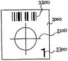
图3是目标标记2000的放大图。底板用循环反射片构成。在反射片上画有表示瞄准点的十字线2100、及同样容易瞄准的以十字线为中心的圆。在圆的上方画有条形码2200,使得在变换为图像时容易读取。在圆的下方画有测定有识别目标标记2000用的数字2300。 FIG. 3 is an enlarged view of
在该目标标记2000的背面粘贴有粘结剂,能够粘贴在任意的对象物体上。另外,也可以与粘结剂以外的其它安装手段组合,例如也可以采用在反射片上粘贴磁性体的结构。 Adhesive is attached to the back of the
另外,目标标记2000是与瞄准目标对应的,以十字线2100为中心的圆相当于容易瞄准的标记。 In addition,
另外,条形码2200相当于能够根据拍摄装置的图像数据进行识别的标识部分,数字2300相当于操作看能够识别的记号。再有,条形码2200相当于通过电气方式能够读取的代码。 In addition, the
如图4及图5所示,测量仪1000是全站仪,内装检测角度(竖直角有水平角)的电子经纬仪及光波测距仪。 As shown in Figures 4 and 5, the
另外,在本实施例中,测量仪1000与数码照相机3000是分开构成的。 In addition, in this embodiment, the measuring
下面根据图5,说明本实施例的测量仪1000的电气构成。 Next, the electrical configuration of the measuring
测量仪1000由测距单元1100、角度测定单元1400、存储单元4200、显示 单元4300、驱动单元4400、控制运算单元4000、以及操作和输入单元5000构成。这里,存储单元4200用来存储数据及程序等。使用者利用显示单元4300及操作和输入单元5000能够对测量仪1000进行操作等。 The measuring
测距单元1100使用光波测距仪,测距单元1100用来根据反射光的位相差及时间差等测定到达测距目标的距离。测距单元1100具有发光单元1110及受光单元1120,从发光单元1110发出的测距光向测定对象物体的方向射出。来自测定对象物体的反射光入射至受光单元1120,采用这样的结构,能够测定到达测定对象物体的距离。 The ranging unit 1100 uses a light wave rangefinder, and the ranging unit 1100 is used to measure the distance to the ranging target according to the phase difference and time difference of the reflected light. The distance measuring unit 1100 includes a light emitting unit 1110 and a light receiving unit 1120 , and the distance measuring light emitted from the light emitting unit 1110 is emitted toward the measurement target object. Reflected light from the object to be measured enters the light receiving unit 1120 , and with such a configuration, the distance to the object to be measured can be measured. the
即,从测量仪1000到测定对象物体的距离能够根据发光单元1110发出脉冲光之后到受光单元1120受光为止的时间差计算出来。另外,该计算在控制运算单元4000内进行。 That is, the distance from the measuring
角度测量单元1400用来计算水平角及竖直角,由竖直角测角单元1410及水平角测角单元1420构成。 The angle measuring unit 1400 is used to calculate the horizontal angle and the vertical angle, and is composed of a vertical angle measuring unit 1410 and a horizontal angle measuring unit 1420 . the
竖直角测角单元1410例如使用竖直角编码器,检测相对于水平或天顶的竖直旋转量。水平角测角单元1420例如使用水平角编码器,能够检测相对于基准方向的水平旋转量。这些编码器例如由安装在旋转部分的转子及形成固定部分的定子构成。 The vertical angle measurement unit 1410 detects the amount of vertical rotation relative to the horizontal or zenith, for example, using a vertical angle encoder. The horizontal angle measurement unit 1420 can detect the amount of horizontal rotation relative to the reference direction by using, for example, a horizontal angle encoder. These encoders are composed, for example, of a rotor mounted on a rotating part and a stator forming a stationary part. the
由竖直角测角单元1410及水平角测角单元1420构成的角度测定单元1400根据检测的水平旋转量及竖直旋转量,计算出水平角及竖直角。 The angle measuring unit 1400 composed of the vertical angle measuring unit 1410 and the horizontal angle measuring unit 1420 calculates the horizontal angle and the vertical angle according to the detected horizontal rotation amount and vertical rotation amount. the
驱动单元4400由水平驱动单元4410及竖直驱动单元4420构成,利用电动机能够使测量仪1000在水平方向及竖直方向旋转。 The driving unit 4400 is composed of a horizontal driving unit 4410 and a vertical driving unit 4420, and can rotate the
控制运算单元4000包含CPU等,进行各种运行等。 The control arithmetic unit 4000 includes a CPU and the like, and performs various operations and the like. the
另外,可以将记忆测量仪1000的运算单元1300运行步骤的程度存入FD、CD、DVD、RAM、ROM、存储器卡等电子存储媒体中。 In addition, the degree of operation steps of the arithmetic unit 1300 of the
测量仪1000如图4所示,由望远镜单元4、支持望远镜单元4使其能够上下旋转的托架部分3、以及支承托架部分3使其能够水平旋转的底盘部分2构成。底盘部分2可通过校平台1安装在三脚架等上。 As shown in FIG. 4 , the
在测量仪1000上,形成操作和输入单元5000的一部分即操作面板,安装成为显示单元4300的一部分的显示器。再有,在望远镜单元4中,物镜露出在外。 In measuring
[第2实施例] [Second embodiment]
下面根据图6及图7说明在加密点不使用目标标记2000的第2实施例。本第2实施例与第1实施例不同,在测量仪1000上装有拍摄装置100。 Next, a second embodiment in which the
作为测量仪1000具有能够将瞄准方向作为图像取入的拍摄装置100。作为测量仪1000的距离测定功能,使用具有捕捉来自自然物体直接的反射而不需要反射棱镜的无棱镜功能的测量仪。 The measuring
如图6及图7所示,测量仪1000瞄准测定对象物体的任意部分,测定距离,同时同样测定水平角及竖直角。然后,拍摄装置100取得测量地点的图像。由于瞄准点是光轴中心,因此与图像中心一致。测量地点由于成为加密点,因此取得至少六个位置的测量值及图像。 As shown in FIGS. 6 and 7 , the
测量后,与第1实施例相同,使用数码照相机3000,至少从两个方向取得图像。 After the measurement, as in the first embodiment, images are acquired from at least two directions using the
然后,将数码照相机3000的图像与用测量仪1000取得的图像进行匹配。修正倍率、辉度及旋转,进行匹配,将瞄准位置作为照相机图像的加密点。 Then, the image of the
在加密点决定后,求出拍摄左右图像的数码照相机3000的相对关系,进行相互标定。与第1实施例相同,加上用测量仪1000的测量得到的加密点的坐标位置,进行绝对标定,变换为正视图像。 After the encryption points are determined, the relative relationship between the
另外,拍摄装置100用来将图像装置数据变换为数字数据,例如是CCD等固体摄像元件。该拍摄装置100由CCD等构成的摄像元件110、以及由摄像元件110的输出信号形成图像信号用的图像电路120构成。 In addition, the imaging device 100 is used to convert image device data into digital data, and is, for example, a solid-state imaging device such as a CCD. The imaging device 100 is composed of an imaging element 110 composed of a CCD or the like, and an image circuit 120 for forming an image signal from an output signal of the imaging element 110 . the
下面根据图8说明本实施例的测量仪1000的电气构成。 Next, the electrical configuration of the measuring
测量仪1000由拍摄装置100、测距单元1100、角度测定ufjq1400、存储单元4200、显示单元4300、驱动单元4400、控制运算单元4000、以及操作和输入单元5000构成。这里,存储单元4200用来存储数据及程序等。使用者利用显示单元4300及操作和输入单元5000能够对测量仪1000进行操作等。 Measuring
另外,除拍摄装置100以外,由于与第1实施例相同,因此省略说明。 In addition, except for the imaging device 100, since it is the same as the first embodiment, description thereof will be omitted. the
下面根据图9说明本实施例的作用。 Next, the function of this embodiment will be described based on FIG. 9 . the
首先,在S91中,在作为测定对象物体10000的加密点的至少六个位置处放置目标标记2000a、2000b、2000c、2000d、2000e、2000f,对这些标记进行测量。 First, in S91 , target marks 2000 a , 2000 b , 2000 c , 2000 d , 2000 e , and 2000 f are placed at at least six positions that are encryption points of the object 10000 to be measured, and these marks are measured. the
接着,在S92中,至少从左右两个方向用数码照相机3000拍摄测定对象 物体10000,并一起拍摄目标标记2000a~目标标记2000f。 Next, in S92, the measurement target object 10000 is photographed with the
然后,在S81中,使用在S91中得到的瞄准点(加密点)进行相互标定。在S81中,根据加密点能够计算出数码照相机3000的立体图像的倾斜与倍率等的关系。 Then, in S81, mutual calibration is performed using the aiming point (encrypted point) obtained in S91. In S81 , the relationship between the inclination of the stereoscopic image of the
接着,在S82中,生成为了使立体图像的加密点对应用的偏移修正图像。S82的偏移修正图像的生成是利用斜影变换进行的。所谓斜影变换是指将数码照相机3000的受光元件上的某一点的照片坐标向其它平面投影的变换。这里是从一个图像抽取特征点,在另一图像的同一水平线上搜索,检索对应点。 Next, in S82 , an offset-corrected image for applying the encrypted point pairs of the stereoscopic image is generated. Generation of the offset-corrected image in S82 is performed using oblique shading transformation. The so-called oblique transformation refers to the transformation of projecting the photo coordinates of a certain point on the light receiving element of the
因而,必须变换为使数码照相机3000沿水平方向平行移动而投影的图像。即,必须将使用的图像变换为使数码照相机3000水平移动之后拍摄的那样的图像。利用这样的变换,即使是自然移动数码照相机3000之后的图像,也能够进行对应点的搜索。再有,在S83中,利用手动或自动来产生加密点。 Therefore, it is necessary to convert the projected image by moving the
然后,在S84中,进行立体匹配。所谓该立体匹配,是对拍摄的两幅图像自动搜索对应点的方法。 Then, in S84, stereo matching is performed. The so-called stereo matching is a method of automatically searching for corresponding points in two captured images. the
接着,在S85中,利用S84中搜索的对应点,能够求出拍摄左右图像的数码照相机3000的相对关系。通过这样,能够定义以在照相机的光轴为中心的三维坐标系。 Next, in S85 , using the corresponding points searched in S84 , the relative relationship between the
通过这样,能够定义以一个数码照相机3000的光轴为中心的三维坐标系。 In this way, a three-dimensional coordinate system centered on the optical axis of one
接着,在S86中,对利用相互标定所得到的模型坐标系提供能够用测量仪测量的加密点坐标位置,进行变换为地上坐标系的绝对标定。 Next, in S86, the model coordinate system obtained by the mutual calibration is provided with an encrypted point coordinate position measurable by a measuring instrument, and an absolute calibration is performed by converting it into a ground coordinate system. the
这里的所谓绝对标定,是将用相互标定所得到的模型坐标系变换为地上坐标系的操作,通过提供在地上测量的三维坐标值,能够变换为图像上的点。 The so-called absolute calibration here is the operation of transforming the model coordinate system obtained by mutual calibration into the ground coordinate system. By providing the three-dimensional coordinate values measured on the ground, it can be transformed into a point on the image. the
接着,在S87中,变换为地上坐标系的三维数据。例如,能够根据该数据显示在地上展开的正视图像。 Next, in S87, it is transformed into three-dimensional data of the ground coordinate system. For example, it is possible to display a front view image spread on the ground based on this data. the
这里来说明正视图像。用照相机拍摄的照片是中心投影照片,而与此不同的是将中心投影照片进行正斜投影的照片称为正视照片。中心投影照片由于是通过镜头拍摄的,因此整个照片不像地图那样的缩小比例尺是均匀的。与此相反,正视照片由于进行了正斜投影,因此缩小比例尺是均匀的,能够与地图同样处理。 Here we illustrate the orthographic image. A photo taken with a camera is a center projection photo, but a photo that is an orthographic projection of a center projection photo is called a front view photo. Since the central projection photo is taken through a lens, the entire photo is not uniform in scale like a map. On the contrary, since the orthographic projection is performed on the orthographic photo, the reduction scale is uniform and can be processed in the same way as a map. the
数码照相机3000的图像是由小的像素单位的数据构成,通过相互标定及绝对标定,对其一个一个像素给予坐标。对于用显示器等二维显示,则根据三 维坐标加上阴影。在坐标变换中,重新计算像素单位的坐标,作为旋转等动作进行显示。 The image of the
如上所述,本实施例涉及利用测量仪1000及数据照相机3000来计算三维坐标数据、并能进行立体显示的三维测量装置。 As described above, this embodiment relates to a three-dimensional measuring device that calculates three-dimensional coordinate data using the
如以上那样构成的本发明,由于具有根据距离及角度来测定瞄准目标的位置用的测量装置、以及从不同的多个方向取得包含前述瞄准目标的测定对象物体图像用的拍摄装置,还具有运算处理手段,前述运算处理手段将前述瞄准目标作为对应点,进行前述拍摄装置的图像匹配,并将前述测量装置测定的瞄准目标的位置与进行了前述匹配的图像中的瞄准目标的位置与进行了前述匹配的图像中的瞄准目标相关联,根据该相关联的关系来计算前述测定对象物体的三维坐标数据,因此具有能够简便正确得到三维坐标数据的效果。 The present invention constituted as above has a measuring device for measuring the position of the aiming target based on a distance and an angle, and an imaging device for obtaining an image of the measurement target object including the aforementioned aiming target from different directions, and also has a computing device. The processing means, the aforementioned arithmetic processing means uses the aforementioned aiming target as a corresponding point, performs image matching of the aforementioned photographing device, and compares the position of the aiming target measured by the aforementioned measuring device with the position of the aiming target in the image on which the matching is performed. The aiming targets in the matched images are correlated, and the three-dimensional coordinate data of the object to be measured is calculated based on the correlation, so that the three-dimensional coordinate data can be easily and accurately obtained. the
工业上的实用性 Industrial applicability
本发明涉及利用测量装置及拍摄装置对三维坐标数据进行运算用的三维测量装置等,特别是能够利用测量装置决定对应点的位置,可进行立体显示。 The present invention relates to a three-dimensional measuring device and the like for calculating three-dimensional coordinate data by using a measuring device and an imaging device. In particular, the position of a corresponding point can be determined by the measuring device and can be displayed in a three-dimensional manner. the
Claims (1)
Applications Claiming Priority (3)
| Application Number | Priority Date | Filing Date | Title |
|---|---|---|---|
| JP207528/2003 | 2003-08-13 | ||
| JP2003207528 | 2003-08-13 | ||
| PCT/JP2004/011862WO2005017644A1 (en) | 2003-08-13 | 2004-08-12 | 3-dimensional measurement device and electronic storage medium |
Publications (2)
| Publication Number | Publication Date |
|---|---|
| CN1701214A CN1701214A (en) | 2005-11-23 |
| CN1701214Btrue CN1701214B (en) | 2011-06-29 |
Family
ID=34190060
Family Applications (1)
| Application Number | Title | Priority Date | Filing Date |
|---|---|---|---|
| CN2004800011104AExpired - Fee RelatedCN1701214B (en) | 2003-08-13 | 2004-08-12 | Three-dimensional measuring device and electronic storage medium |
Country Status (4)
| Country | Link |
|---|---|
| US (1) | US20060167648A1 (en) |
| EP (1) | EP1655573B1 (en) |
| JP (1) | JPWO2005017644A1 (en) |
| CN (1) | CN1701214B (en) |
Families Citing this family (33)
| Publication number | Priority date | Publication date | Assignee | Title |
|---|---|---|---|---|
| JP4977339B2 (en)* | 2005-07-11 | 2012-07-18 | 株式会社トプコン | Geographic data collection device |
| US7933001B2 (en) | 2005-07-11 | 2011-04-26 | Kabushiki Kaisha Topcon | Geographic data collecting system |
| US20070065004A1 (en)* | 2005-08-01 | 2007-03-22 | Topcon Corporation | Three-dimensional measurement system and method of the same, and color-coded mark |
| US8024144B2 (en)* | 2005-09-12 | 2011-09-20 | Trimble Jena Gmbh | Surveying instrument and method of providing survey data of a target region using a surveying instrument |
| US20080123903A1 (en)* | 2006-07-03 | 2008-05-29 | Pentax Industrial Instruments Co., Ltd. | Surveying apparatus |
| US20100109902A1 (en)* | 2007-03-30 | 2010-05-06 | Koninklijke Philips Electronics N.V. | Method and device for system control |
| JP5207719B2 (en)* | 2007-12-05 | 2013-06-12 | 株式会社トプコン | Label with color code, color code extraction means, and three-dimensional measurement system |
| WO2009100773A1 (en) | 2008-02-12 | 2009-08-20 | Trimble Ab | Localization of a surveying instrument in relation to a ground mark |
| US8625086B2 (en) | 2008-02-12 | 2014-01-07 | Trimble Ab | Determining coordinates of a target in relation to a survey instrument having a camera |
| US8897482B2 (en) | 2008-02-29 | 2014-11-25 | Trimble Ab | Stereo photogrammetry from a single station using a surveying instrument with an eccentric camera |
| EP2247922B1 (en)* | 2008-02-29 | 2015-03-25 | Trimble AB | Determining coordinates of a target in relation to a survey instrument having at least two cameras |
| JP5150307B2 (en)* | 2008-03-03 | 2013-02-20 | 株式会社トプコン | Geographic data collection device |
| JP5150310B2 (en)* | 2008-03-04 | 2013-02-20 | 株式会社トプコン | Geographic data collection device |
| US8887449B2 (en)* | 2008-03-28 | 2014-11-18 | Toshiba Plant Systems & Services Corporation | Benchmark marking tool and benchmark marking method |
| US8473256B2 (en)* | 2008-11-04 | 2013-06-25 | Airbus Operations Gmbh | System and method for providing a digital three-dimensional data model |
| FR2954520B1 (en)* | 2009-12-18 | 2012-09-21 | Thales Sa | METHOD FOR THE DESIGNATION OF A TARGET FOR A TERMINAL IMAGING GUIDED ARMING |
| JP5465128B2 (en) | 2010-08-11 | 2014-04-09 | 株式会社トプコン | Point cloud position data processing device, point cloud position data processing system, point cloud position data processing method, and point cloud position data processing program |
| JP5698480B2 (en) | 2010-09-02 | 2015-04-08 | 株式会社トプコン | Measuring method and measuring device |
| CN102155940B (en)* | 2011-03-17 | 2012-10-17 | 北京信息科技大学 | Stereo target for binocular vision positioning and tracking system |
| CN102324044A (en)* | 2011-09-09 | 2012-01-18 | 上海合合信息科技发展有限公司 | Card information acquisition method and system |
| US10794692B2 (en)* | 2013-02-28 | 2020-10-06 | Fnv Ip B.V. | Offshore positioning system and method |
| WO2014133381A1 (en)* | 2013-02-28 | 2014-09-04 | Fugro N.V. | Offshore positioning system and method |
| CN104236519B (en)* | 2014-09-22 | 2017-09-22 | 浙江荣胜工具有限公司 | Three-dimensional perspective measurement apparatus |
| CN104567835B (en)* | 2014-12-18 | 2017-12-08 | 福建省马尾造船股份有限公司 | Total powerstation reflection unit |
| CN104567727B (en)* | 2014-12-24 | 2017-05-24 | 天津大学 | Global unified calibration method for linear structured light profile sensor through three-dimensional target |
| JP6510247B2 (en)* | 2015-01-27 | 2019-05-08 | 株式会社トプコン | Survey data processing apparatus, survey data processing method and program |
| CN106052647A (en)* | 2016-05-09 | 2016-10-26 | 华广发 | A compass positioning technique for overlooking 360 degrees' full view and twenty four mountains |
| JP7012485B2 (en)* | 2016-12-27 | 2022-01-28 | 株式会社ワコム | Image information processing device and image information processing method |
| US11257234B2 (en)* | 2019-05-24 | 2022-02-22 | Nanjing Polagis Technology Co. Ltd | Method for three-dimensional measurement and calculation of the geographic position and height of a target object based on street view images |
| CN110300264B (en)* | 2019-06-28 | 2021-03-12 | Oppo广东移动通信有限公司 | Image processing method, device, mobile terminal and storage medium |
| CN111179339B (en)* | 2019-12-13 | 2024-03-08 | 深圳市瑞立视多媒体科技有限公司 | Coordinate positioning method, device, equipment and storage medium based on triangulation |
| CN115345993A (en)* | 2022-08-10 | 2022-11-15 | 先临三维科技股份有限公司 | Three-dimensional reconstruction method, device and system |
| CN116045812A (en)* | 2023-02-24 | 2023-05-02 | 埃洛斯医疗(深圳)有限公司 | A Camera Projection Coordinate Measuring Instrument and Measuring and Calculating Method with Triangular Pyramid |
Citations (4)
| Publication number | Priority date | Publication date | Assignee | Title |
|---|---|---|---|---|
| US20020001406A1 (en)* | 2000-03-30 | 2002-01-03 | Kabushiki Kaisha Topcon | Stereo image measuring device |
| US6382510B1 (en)* | 1999-02-02 | 2002-05-07 | Industrial Technology Research Institute | Automatic inspection system using barcode localization and method thereof |
| CN1362612A (en)* | 2000-12-28 | 2002-08-07 | 株式会社拓普康 | Measuring apparatus |
| US6509973B2 (en)* | 2000-03-31 | 2003-01-21 | Minolta Co., Ltd. | Apparatus for measuring three-dimensional shape |
Family Cites Families (12)
| Publication number | Priority date | Publication date | Assignee | Title |
|---|---|---|---|---|
| US5155558A (en)* | 1990-09-19 | 1992-10-13 | E. I. Du Pont De Nemours And Company | Method and apparatus for analyzing the appearance features of a surface |
| JP3079186B2 (en)* | 1995-09-28 | 2000-08-21 | 株式会社小松製作所 | Structure measurement system |
| JP3347035B2 (en)* | 1997-10-29 | 2002-11-20 | 日立建機株式会社 | Optical declination measuring device and underground excavator position measuring device |
| WO2000025089A1 (en)* | 1998-10-28 | 2000-05-04 | Measurement Devices Limited | Apparatus and method for obtaining 3d images |
| DE19922341C2 (en)* | 1999-05-14 | 2002-08-29 | Zsp Geodaetische Sys Gmbh | Method and arrangement for determining the spatial coordinates of at least one object point |
| JP4328919B2 (en)* | 1999-05-21 | 2009-09-09 | 株式会社トプコン | Target device |
| JP2001099647A (en)* | 1999-09-29 | 2001-04-13 | Kumagai Gumi Co Ltd | Surveying device and target |
| JP4444440B2 (en)* | 2000-03-30 | 2010-03-31 | 株式会社トプコン | Stereo image measuring device |
| JP3530978B2 (en)* | 2000-12-28 | 2004-05-24 | 鹿島建設株式会社 | Image measurement method and recording medium recording image measurement program |
| WO2002063241A1 (en)* | 2001-02-08 | 2002-08-15 | Nkk Corporation | Three-dimensional coordinate measuring method, three-dimensional coordinate measuring apparatus, and method for building large-sized structure |
| EP1329690A1 (en)* | 2002-01-22 | 2003-07-23 | Leica Geosystems AG | Method and device for automatic locating of targets |
| US20040017334A1 (en)* | 2002-07-26 | 2004-01-29 | Chan Hau Man | Three-dimensional image display |
- 2004
- 2004-08-12JPJP2005513207Apatent/JPWO2005017644A1/enactivePending
- 2004-08-12CNCN2004800011104Apatent/CN1701214B/ennot_activeExpired - Fee Related
- 2004-08-12USUS10/531,230patent/US20060167648A1/ennot_activeAbandoned
- 2004-08-12EPEP04771823Apatent/EP1655573B1/ennot_activeExpired - Lifetime
Patent Citations (4)
| Publication number | Priority date | Publication date | Assignee | Title |
|---|---|---|---|---|
| US6382510B1 (en)* | 1999-02-02 | 2002-05-07 | Industrial Technology Research Institute | Automatic inspection system using barcode localization and method thereof |
| US20020001406A1 (en)* | 2000-03-30 | 2002-01-03 | Kabushiki Kaisha Topcon | Stereo image measuring device |
| US6509973B2 (en)* | 2000-03-31 | 2003-01-21 | Minolta Co., Ltd. | Apparatus for measuring three-dimensional shape |
| CN1362612A (en)* | 2000-12-28 | 2002-08-07 | 株式会社拓普康 | Measuring apparatus |
Non-Patent Citations (2)
| Title |
|---|
| JP特开2002-202124A 2002.07.19 |
| US 20020001406 A1,全文. |
Also Published As
| Publication number | Publication date |
|---|---|
| US20060167648A1 (en) | 2006-07-27 |
| WO2005017644A2 (en) | 2005-02-24 |
| EP1655573A4 (en) | 2010-11-03 |
| JPWO2005017644A1 (en) | 2006-11-24 |
| CN1701214A (en) | 2005-11-23 |
| EP1655573B1 (en) | 2012-07-11 |
| WO2005017644A3 (en) | 2005-03-31 |
| EP1655573A2 (en) | 2006-05-10 |
Similar Documents
| Publication | Publication Date | Title |
|---|---|---|
| CN1701214B (en) | Three-dimensional measuring device and electronic storage medium | |
| EP1607718B1 (en) | Surveying instrument and electronic storage medium | |
| JP7300948B2 (en) | Survey data processing device, survey data processing method, program for survey data processing | |
| CN113532329B (en) | Calibration method with projected light spot as calibration point | |
| US9322652B2 (en) | Stereo photogrammetry from a single station using a surveying instrument with an eccentric camera | |
| US10187567B2 (en) | Method and handheld distance measurement device for indirect distance measurement by means of image-assisted angle determination function | |
| EP1493990B1 (en) | Surveying instrument and electronic storage medium | |
| CN100565107C (en) | geographic data collection device | |
| JP4052382B2 (en) | Non-contact image measuring device | |
| CN112254670B (en) | 3D information acquisition equipment based on optical scanning and intelligent vision integration | |
| CN101561273A (en) | Geographical data collecting device | |
| JP2003279351A (en) | Surveying apparatus and method for acquiring image data using surveying apparatus | |
| JP2007514943A (en) | Calibration of surveying instrument | |
| US10943360B1 (en) | Photogrammetric machine measure up | |
| JP5007885B2 (en) | Three-dimensional survey system and electronic storage medium | |
| JP2018013343A (en) | Survey assistance apparatus | |
| CN112082486B (en) | Handheld intelligent 3D information acquisition equipment | |
| CN112254676B (en) | Portable intelligent 3D information acquisition equipment | |
| CN112254677B (en) | Multi-position combined 3D acquisition system and method based on handheld device | |
| JP2008014682A (en) | Surveying instrument | |
| JP2004085539A (en) | Surveying system | |
| JP2003177019A (en) | Method for camera posture calculation by free photographing | |
| JP5133620B2 (en) | Surveying instrument | |
| JP2024110640A (en) | OPTICAL DATA PROCESSING APPARATUS, OPTICAL DATA PROCESSING METHOD, AND OPTICAL DATA PROCESSING PROGRAM | |
| JP5127323B2 (en) | Surveying instrument |
Legal Events
| Date | Code | Title | Description |
|---|---|---|---|
| C06 | Publication | ||
| PB01 | Publication | ||
| C10 | Entry into substantive examination | ||
| SE01 | Entry into force of request for substantive examination | ||
| C14 | Grant of patent or utility model | ||
| GR01 | Patent grant | ||
| CF01 | Termination of patent right due to non-payment of annual fee | ||
| CF01 | Termination of patent right due to non-payment of annual fee | Granted publication date:20110629 Termination date:20200812 |