CN1700458A - Semiconductor package with first and second conductive bumps and manufacturing method thereof - Google Patents
Semiconductor package with first and second conductive bumps and manufacturing method thereofDownload PDFInfo
- Publication number
- CN1700458A CN1700458ACNA2005100667995ACN200510066799ACN1700458ACN 1700458 ACN1700458 ACN 1700458ACN A2005100667995 ACNA2005100667995 ACN A2005100667995ACN 200510066799 ACN200510066799 ACN 200510066799ACN 1700458 ACN1700458 ACN 1700458A
- Authority
- CN
- China
- Prior art keywords
- semiconductor chip
- lower semiconductor
- bonding pad
- base frame
- package
- Prior art date
- Legal status (The legal status is an assumption and is not a legal conclusion. Google has not performed a legal analysis and makes no representation as to the accuracy of the status listed.)
- Pending
Links
Images


Classifications
- H—ELECTRICITY
- H01—ELECTRIC ELEMENTS
- H01L—SEMICONDUCTOR DEVICES NOT COVERED BY CLASS H10
- H01L23/00—Details of semiconductor or other solid state devices
- H01L23/48—Arrangements for conducting electric current to or from the solid state body in operation, e.g. leads, terminal arrangements ; Selection of materials therefor
- H01L23/50—Arrangements for conducting electric current to or from the solid state body in operation, e.g. leads, terminal arrangements ; Selection of materials therefor for integrated circuit devices, e.g. power bus, number of leads
- F—MECHANICAL ENGINEERING; LIGHTING; HEATING; WEAPONS; BLASTING
- F24—HEATING; RANGES; VENTILATING
- F24C—DOMESTIC STOVES OR RANGES ; DETAILS OF DOMESTIC STOVES OR RANGES, OF GENERAL APPLICATION
- F24C3/00—Stoves or ranges for gaseous fuels
- F24C3/14—Stoves or ranges for gaseous fuels with special adaptation for travelling, e.g. collapsible
- F—MECHANICAL ENGINEERING; LIGHTING; HEATING; WEAPONS; BLASTING
- F24—HEATING; RANGES; VENTILATING
- F24C—DOMESTIC STOVES OR RANGES ; DETAILS OF DOMESTIC STOVES OR RANGES, OF GENERAL APPLICATION
- F24C3/00—Stoves or ranges for gaseous fuels
- F24C3/12—Arrangement or mounting of control or safety devices
- F24C3/126—Arrangement or mounting of control or safety devices on ranges
- H—ELECTRICITY
- H01—ELECTRIC ELEMENTS
- H01L—SEMICONDUCTOR DEVICES NOT COVERED BY CLASS H10
- H01L21/00—Processes or apparatus adapted for the manufacture or treatment of semiconductor or solid state devices or of parts thereof
- H01L21/02—Manufacture or treatment of semiconductor devices or of parts thereof
- H01L21/04—Manufacture or treatment of semiconductor devices or of parts thereof the devices having potential barriers, e.g. a PN junction, depletion layer or carrier concentration layer
- H01L21/50—Assembly of semiconductor devices using processes or apparatus not provided for in a single one of the groups H01L21/18 - H01L21/326 or H10D48/04 - H10D48/07 e.g. sealing of a cap to a base of a container
- H01L21/56—Encapsulations, e.g. encapsulation layers, coatings
- H01L21/563—Encapsulation of active face of flip-chip device, e.g. underfilling or underencapsulation of flip-chip, encapsulation preform on chip or mounting substrate
- H—ELECTRICITY
- H01—ELECTRIC ELEMENTS
- H01L—SEMICONDUCTOR DEVICES NOT COVERED BY CLASS H10
- H01L23/00—Details of semiconductor or other solid state devices
- H01L23/28—Encapsulations, e.g. encapsulating layers, coatings, e.g. for protection
- H01L23/31—Encapsulations, e.g. encapsulating layers, coatings, e.g. for protection characterised by the arrangement or shape
- H01L23/3107—Encapsulations, e.g. encapsulating layers, coatings, e.g. for protection characterised by the arrangement or shape the device being completely enclosed
- H01L23/3121—Encapsulations, e.g. encapsulating layers, coatings, e.g. for protection characterised by the arrangement or shape the device being completely enclosed a substrate forming part of the encapsulation
- H01L23/3128—Encapsulations, e.g. encapsulating layers, coatings, e.g. for protection characterised by the arrangement or shape the device being completely enclosed a substrate forming part of the encapsulation the substrate having spherical bumps for external connection
- H—ELECTRICITY
- H01—ELECTRIC ELEMENTS
- H01L—SEMICONDUCTOR DEVICES NOT COVERED BY CLASS H10
- H01L23/00—Details of semiconductor or other solid state devices
- H01L23/48—Arrangements for conducting electric current to or from the solid state body in operation, e.g. leads, terminal arrangements ; Selection of materials therefor
- H01L23/488—Arrangements for conducting electric current to or from the solid state body in operation, e.g. leads, terminal arrangements ; Selection of materials therefor consisting of soldered or bonded constructions
- H01L23/495—Lead-frames or other flat leads
- H01L23/49575—Assemblies of semiconductor devices on lead frames
- H—ELECTRICITY
- H01—ELECTRIC ELEMENTS
- H01L—SEMICONDUCTOR DEVICES NOT COVERED BY CLASS H10
- H01L24/00—Arrangements for connecting or disconnecting semiconductor or solid-state bodies; Methods or apparatus related thereto
- H01L24/01—Means for bonding being attached to, or being formed on, the surface to be connected, e.g. chip-to-package, die-attach, "first-level" interconnects; Manufacturing methods related thereto
- H01L24/02—Bonding areas ; Manufacturing methods related thereto
- H01L24/03—Manufacturing methods
- H—ELECTRICITY
- H01—ELECTRIC ELEMENTS
- H01L—SEMICONDUCTOR DEVICES NOT COVERED BY CLASS H10
- H01L24/00—Arrangements for connecting or disconnecting semiconductor or solid-state bodies; Methods or apparatus related thereto
- H01L24/01—Means for bonding being attached to, or being formed on, the surface to be connected, e.g. chip-to-package, die-attach, "first-level" interconnects; Manufacturing methods related thereto
- H01L24/02—Bonding areas ; Manufacturing methods related thereto
- H01L24/04—Structure, shape, material or disposition of the bonding areas prior to the connecting process
- H01L24/05—Structure, shape, material or disposition of the bonding areas prior to the connecting process of an individual bonding area
- H—ELECTRICITY
- H01—ELECTRIC ELEMENTS
- H01L—SEMICONDUCTOR DEVICES NOT COVERED BY CLASS H10
- H01L24/00—Arrangements for connecting or disconnecting semiconductor or solid-state bodies; Methods or apparatus related thereto
- H01L24/01—Means for bonding being attached to, or being formed on, the surface to be connected, e.g. chip-to-package, die-attach, "first-level" interconnects; Manufacturing methods related thereto
- H01L24/42—Wire connectors; Manufacturing methods related thereto
- H01L24/47—Structure, shape, material or disposition of the wire connectors after the connecting process
- H01L24/48—Structure, shape, material or disposition of the wire connectors after the connecting process of an individual wire connector
- H—ELECTRICITY
- H01—ELECTRIC ELEMENTS
- H01L—SEMICONDUCTOR DEVICES NOT COVERED BY CLASS H10
- H01L24/00—Arrangements for connecting or disconnecting semiconductor or solid-state bodies; Methods or apparatus related thereto
- H01L24/91—Methods for connecting semiconductor or solid state bodies including different methods provided for in two or more of groups H01L24/80 - H01L24/90
- H—ELECTRICITY
- H01—ELECTRIC ELEMENTS
- H01L—SEMICONDUCTOR DEVICES NOT COVERED BY CLASS H10
- H01L25/00—Assemblies consisting of a plurality of semiconductor or other solid state devices
- H01L25/03—Assemblies consisting of a plurality of semiconductor or other solid state devices all the devices being of a type provided for in a single subclass of subclasses H10B, H10D, H10F, H10H, H10K or H10N, e.g. assemblies of rectifier diodes
- H01L25/04—Assemblies consisting of a plurality of semiconductor or other solid state devices all the devices being of a type provided for in a single subclass of subclasses H10B, H10D, H10F, H10H, H10K or H10N, e.g. assemblies of rectifier diodes the devices not having separate containers
- H01L25/065—Assemblies consisting of a plurality of semiconductor or other solid state devices all the devices being of a type provided for in a single subclass of subclasses H10B, H10D, H10F, H10H, H10K or H10N, e.g. assemblies of rectifier diodes the devices not having separate containers the devices being of a type provided for in group H10D89/00
- H01L25/0657—Stacked arrangements of devices
- H—ELECTRICITY
- H01—ELECTRIC ELEMENTS
- H01L—SEMICONDUCTOR DEVICES NOT COVERED BY CLASS H10
- H01L2224/00—Indexing scheme for arrangements for connecting or disconnecting semiconductor or solid-state bodies and methods related thereto as covered by H01L24/00
- H01L2224/01—Means for bonding being attached to, or being formed on, the surface to be connected, e.g. chip-to-package, die-attach, "first-level" interconnects; Manufacturing methods related thereto
- H01L2224/02—Bonding areas; Manufacturing methods related thereto
- H01L2224/04—Structure, shape, material or disposition of the bonding areas prior to the connecting process
- H01L2224/0401—Bonding areas specifically adapted for bump connectors, e.g. under bump metallisation [UBM]
- H—ELECTRICITY
- H01—ELECTRIC ELEMENTS
- H01L—SEMICONDUCTOR DEVICES NOT COVERED BY CLASS H10
- H01L2224/00—Indexing scheme for arrangements for connecting or disconnecting semiconductor or solid-state bodies and methods related thereto as covered by H01L24/00
- H01L2224/01—Means for bonding being attached to, or being formed on, the surface to be connected, e.g. chip-to-package, die-attach, "first-level" interconnects; Manufacturing methods related thereto
- H01L2224/02—Bonding areas; Manufacturing methods related thereto
- H01L2224/04—Structure, shape, material or disposition of the bonding areas prior to the connecting process
- H01L2224/04042—Bonding areas specifically adapted for wire connectors, e.g. wirebond pads
- H—ELECTRICITY
- H01—ELECTRIC ELEMENTS
- H01L—SEMICONDUCTOR DEVICES NOT COVERED BY CLASS H10
- H01L2224/00—Indexing scheme for arrangements for connecting or disconnecting semiconductor or solid-state bodies and methods related thereto as covered by H01L24/00
- H01L2224/01—Means for bonding being attached to, or being formed on, the surface to be connected, e.g. chip-to-package, die-attach, "first-level" interconnects; Manufacturing methods related thereto
- H01L2224/02—Bonding areas; Manufacturing methods related thereto
- H01L2224/04—Structure, shape, material or disposition of the bonding areas prior to the connecting process
- H01L2224/05—Structure, shape, material or disposition of the bonding areas prior to the connecting process of an individual bonding area
- H01L2224/0554—External layer
- H01L2224/0555—Shape
- H01L2224/05552—Shape in top view
- H01L2224/05554—Shape in top view being square
- H—ELECTRICITY
- H01—ELECTRIC ELEMENTS
- H01L—SEMICONDUCTOR DEVICES NOT COVERED BY CLASS H10
- H01L2224/00—Indexing scheme for arrangements for connecting or disconnecting semiconductor or solid-state bodies and methods related thereto as covered by H01L24/00
- H01L2224/01—Means for bonding being attached to, or being formed on, the surface to be connected, e.g. chip-to-package, die-attach, "first-level" interconnects; Manufacturing methods related thereto
- H01L2224/02—Bonding areas; Manufacturing methods related thereto
- H01L2224/04—Structure, shape, material or disposition of the bonding areas prior to the connecting process
- H01L2224/05—Structure, shape, material or disposition of the bonding areas prior to the connecting process of an individual bonding area
- H01L2224/0554—External layer
- H01L2224/0555—Shape
- H01L2224/05556—Shape in side view
- H—ELECTRICITY
- H01—ELECTRIC ELEMENTS
- H01L—SEMICONDUCTOR DEVICES NOT COVERED BY CLASS H10
- H01L2224/00—Indexing scheme for arrangements for connecting or disconnecting semiconductor or solid-state bodies and methods related thereto as covered by H01L24/00
- H01L2224/01—Means for bonding being attached to, or being formed on, the surface to be connected, e.g. chip-to-package, die-attach, "first-level" interconnects; Manufacturing methods related thereto
- H01L2224/02—Bonding areas; Manufacturing methods related thereto
- H01L2224/04—Structure, shape, material or disposition of the bonding areas prior to the connecting process
- H01L2224/05—Structure, shape, material or disposition of the bonding areas prior to the connecting process of an individual bonding area
- H01L2224/0554—External layer
- H01L2224/05599—Material
- H01L2224/056—Material with a principal constituent of the material being a metal or a metalloid, e.g. boron [B], silicon [Si], germanium [Ge], arsenic [As], antimony [Sb], tellurium [Te] and polonium [Po], and alloys thereof
- H01L2224/05638—Material with a principal constituent of the material being a metal or a metalloid, e.g. boron [B], silicon [Si], germanium [Ge], arsenic [As], antimony [Sb], tellurium [Te] and polonium [Po], and alloys thereof the principal constituent melting at a temperature of greater than or equal to 950°C and less than 1550°C
- H01L2224/05639—Silver [Ag] as principal constituent
- H—ELECTRICITY
- H01—ELECTRIC ELEMENTS
- H01L—SEMICONDUCTOR DEVICES NOT COVERED BY CLASS H10
- H01L2224/00—Indexing scheme for arrangements for connecting or disconnecting semiconductor or solid-state bodies and methods related thereto as covered by H01L24/00
- H01L2224/01—Means for bonding being attached to, or being formed on, the surface to be connected, e.g. chip-to-package, die-attach, "first-level" interconnects; Manufacturing methods related thereto
- H01L2224/02—Bonding areas; Manufacturing methods related thereto
- H01L2224/04—Structure, shape, material or disposition of the bonding areas prior to the connecting process
- H01L2224/05—Structure, shape, material or disposition of the bonding areas prior to the connecting process of an individual bonding area
- H01L2224/0554—External layer
- H01L2224/05599—Material
- H01L2224/056—Material with a principal constituent of the material being a metal or a metalloid, e.g. boron [B], silicon [Si], germanium [Ge], arsenic [As], antimony [Sb], tellurium [Te] and polonium [Po], and alloys thereof
- H01L2224/05638—Material with a principal constituent of the material being a metal or a metalloid, e.g. boron [B], silicon [Si], germanium [Ge], arsenic [As], antimony [Sb], tellurium [Te] and polonium [Po], and alloys thereof the principal constituent melting at a temperature of greater than or equal to 950°C and less than 1550°C
- H01L2224/05644—Gold [Au] as principal constituent
- H—ELECTRICITY
- H01—ELECTRIC ELEMENTS
- H01L—SEMICONDUCTOR DEVICES NOT COVERED BY CLASS H10
- H01L2224/00—Indexing scheme for arrangements for connecting or disconnecting semiconductor or solid-state bodies and methods related thereto as covered by H01L24/00
- H01L2224/01—Means for bonding being attached to, or being formed on, the surface to be connected, e.g. chip-to-package, die-attach, "first-level" interconnects; Manufacturing methods related thereto
- H01L2224/02—Bonding areas; Manufacturing methods related thereto
- H01L2224/04—Structure, shape, material or disposition of the bonding areas prior to the connecting process
- H01L2224/05—Structure, shape, material or disposition of the bonding areas prior to the connecting process of an individual bonding area
- H01L2224/0554—External layer
- H01L2224/05599—Material
- H01L2224/056—Material with a principal constituent of the material being a metal or a metalloid, e.g. boron [B], silicon [Si], germanium [Ge], arsenic [As], antimony [Sb], tellurium [Te] and polonium [Po], and alloys thereof
- H01L2224/05638—Material with a principal constituent of the material being a metal or a metalloid, e.g. boron [B], silicon [Si], germanium [Ge], arsenic [As], antimony [Sb], tellurium [Te] and polonium [Po], and alloys thereof the principal constituent melting at a temperature of greater than or equal to 950°C and less than 1550°C
- H01L2224/05647—Copper [Cu] as principal constituent
- H—ELECTRICITY
- H01—ELECTRIC ELEMENTS
- H01L—SEMICONDUCTOR DEVICES NOT COVERED BY CLASS H10
- H01L2224/00—Indexing scheme for arrangements for connecting or disconnecting semiconductor or solid-state bodies and methods related thereto as covered by H01L24/00
- H01L2224/01—Means for bonding being attached to, or being formed on, the surface to be connected, e.g. chip-to-package, die-attach, "first-level" interconnects; Manufacturing methods related thereto
- H01L2224/02—Bonding areas; Manufacturing methods related thereto
- H01L2224/04—Structure, shape, material or disposition of the bonding areas prior to the connecting process
- H01L2224/05—Structure, shape, material or disposition of the bonding areas prior to the connecting process of an individual bonding area
- H01L2224/0554—External layer
- H01L2224/05599—Material
- H01L2224/056—Material with a principal constituent of the material being a metal or a metalloid, e.g. boron [B], silicon [Si], germanium [Ge], arsenic [As], antimony [Sb], tellurium [Te] and polonium [Po], and alloys thereof
- H01L2224/05638—Material with a principal constituent of the material being a metal or a metalloid, e.g. boron [B], silicon [Si], germanium [Ge], arsenic [As], antimony [Sb], tellurium [Te] and polonium [Po], and alloys thereof the principal constituent melting at a temperature of greater than or equal to 950°C and less than 1550°C
- H01L2224/05655—Nickel [Ni] as principal constituent
- H—ELECTRICITY
- H01—ELECTRIC ELEMENTS
- H01L—SEMICONDUCTOR DEVICES NOT COVERED BY CLASS H10
- H01L2224/00—Indexing scheme for arrangements for connecting or disconnecting semiconductor or solid-state bodies and methods related thereto as covered by H01L24/00
- H01L2224/01—Means for bonding being attached to, or being formed on, the surface to be connected, e.g. chip-to-package, die-attach, "first-level" interconnects; Manufacturing methods related thereto
- H01L2224/10—Bump connectors; Manufacturing methods related thereto
- H01L2224/12—Structure, shape, material or disposition of the bump connectors prior to the connecting process
- H01L2224/13—Structure, shape, material or disposition of the bump connectors prior to the connecting process of an individual bump connector
- H01L2224/13001—Core members of the bump connector
- H01L2224/13099—Material
- H01L2224/131—Material with a principal constituent of the material being a metal or a metalloid, e.g. boron [B], silicon [Si], germanium [Ge], arsenic [As], antimony [Sb], tellurium [Te] and polonium [Po], and alloys thereof
- H01L2224/13138—Material with a principal constituent of the material being a metal or a metalloid, e.g. boron [B], silicon [Si], germanium [Ge], arsenic [As], antimony [Sb], tellurium [Te] and polonium [Po], and alloys thereof the principal constituent melting at a temperature of greater than or equal to 950°C and less than 1550°C
- H01L2224/13144—Gold [Au] as principal constituent
- H—ELECTRICITY
- H01—ELECTRIC ELEMENTS
- H01L—SEMICONDUCTOR DEVICES NOT COVERED BY CLASS H10
- H01L2224/00—Indexing scheme for arrangements for connecting or disconnecting semiconductor or solid-state bodies and methods related thereto as covered by H01L24/00
- H01L2224/01—Means for bonding being attached to, or being formed on, the surface to be connected, e.g. chip-to-package, die-attach, "first-level" interconnects; Manufacturing methods related thereto
- H01L2224/10—Bump connectors; Manufacturing methods related thereto
- H01L2224/15—Structure, shape, material or disposition of the bump connectors after the connecting process
- H01L2224/16—Structure, shape, material or disposition of the bump connectors after the connecting process of an individual bump connector
- H01L2224/161—Disposition
- H01L2224/16135—Disposition the bump connector connecting between different semiconductor or solid-state bodies, i.e. chip-to-chip
- H01L2224/16145—Disposition the bump connector connecting between different semiconductor or solid-state bodies, i.e. chip-to-chip the bodies being stacked
- H—ELECTRICITY
- H01—ELECTRIC ELEMENTS
- H01L—SEMICONDUCTOR DEVICES NOT COVERED BY CLASS H10
- H01L2224/00—Indexing scheme for arrangements for connecting or disconnecting semiconductor or solid-state bodies and methods related thereto as covered by H01L24/00
- H01L2224/01—Means for bonding being attached to, or being formed on, the surface to be connected, e.g. chip-to-package, die-attach, "first-level" interconnects; Manufacturing methods related thereto
- H01L2224/10—Bump connectors; Manufacturing methods related thereto
- H01L2224/15—Structure, shape, material or disposition of the bump connectors after the connecting process
- H01L2224/16—Structure, shape, material or disposition of the bump connectors after the connecting process of an individual bump connector
- H01L2224/161—Disposition
- H01L2224/16151—Disposition the bump connector connecting between a semiconductor or solid-state body and an item not being a semiconductor or solid-state body, e.g. chip-to-substrate, chip-to-passive
- H01L2224/16221—Disposition the bump connector connecting between a semiconductor or solid-state body and an item not being a semiconductor or solid-state body, e.g. chip-to-substrate, chip-to-passive the body and the item being stacked
- H01L2224/16265—Disposition the bump connector connecting between a semiconductor or solid-state body and an item not being a semiconductor or solid-state body, e.g. chip-to-substrate, chip-to-passive the body and the item being stacked the item being a discrete passive component
- H—ELECTRICITY
- H01—ELECTRIC ELEMENTS
- H01L—SEMICONDUCTOR DEVICES NOT COVERED BY CLASS H10
- H01L2224/00—Indexing scheme for arrangements for connecting or disconnecting semiconductor or solid-state bodies and methods related thereto as covered by H01L24/00
- H01L2224/01—Means for bonding being attached to, or being formed on, the surface to be connected, e.g. chip-to-package, die-attach, "first-level" interconnects; Manufacturing methods related thereto
- H01L2224/26—Layer connectors, e.g. plate connectors, solder or adhesive layers; Manufacturing methods related thereto
- H01L2224/31—Structure, shape, material or disposition of the layer connectors after the connecting process
- H01L2224/32—Structure, shape, material or disposition of the layer connectors after the connecting process of an individual layer connector
- H01L2224/321—Disposition
- H01L2224/32135—Disposition the layer connector connecting between different semiconductor or solid-state bodies, i.e. chip-to-chip
- H01L2224/32145—Disposition the layer connector connecting between different semiconductor or solid-state bodies, i.e. chip-to-chip the bodies being stacked
- H—ELECTRICITY
- H01—ELECTRIC ELEMENTS
- H01L—SEMICONDUCTOR DEVICES NOT COVERED BY CLASS H10
- H01L2224/00—Indexing scheme for arrangements for connecting or disconnecting semiconductor or solid-state bodies and methods related thereto as covered by H01L24/00
- H01L2224/01—Means for bonding being attached to, or being formed on, the surface to be connected, e.g. chip-to-package, die-attach, "first-level" interconnects; Manufacturing methods related thereto
- H01L2224/26—Layer connectors, e.g. plate connectors, solder or adhesive layers; Manufacturing methods related thereto
- H01L2224/31—Structure, shape, material or disposition of the layer connectors after the connecting process
- H01L2224/32—Structure, shape, material or disposition of the layer connectors after the connecting process of an individual layer connector
- H01L2224/321—Disposition
- H01L2224/32151—Disposition the layer connector connecting between a semiconductor or solid-state body and an item not being a semiconductor or solid-state body, e.g. chip-to-substrate, chip-to-passive
- H01L2224/32221—Disposition the layer connector connecting between a semiconductor or solid-state body and an item not being a semiconductor or solid-state body, e.g. chip-to-substrate, chip-to-passive the body and the item being stacked
- H01L2224/32225—Disposition the layer connector connecting between a semiconductor or solid-state body and an item not being a semiconductor or solid-state body, e.g. chip-to-substrate, chip-to-passive the body and the item being stacked the item being non-metallic, e.g. insulating substrate with or without metallisation
- H—ELECTRICITY
- H01—ELECTRIC ELEMENTS
- H01L—SEMICONDUCTOR DEVICES NOT COVERED BY CLASS H10
- H01L2224/00—Indexing scheme for arrangements for connecting or disconnecting semiconductor or solid-state bodies and methods related thereto as covered by H01L24/00
- H01L2224/01—Means for bonding being attached to, or being formed on, the surface to be connected, e.g. chip-to-package, die-attach, "first-level" interconnects; Manufacturing methods related thereto
- H01L2224/26—Layer connectors, e.g. plate connectors, solder or adhesive layers; Manufacturing methods related thereto
- H01L2224/31—Structure, shape, material or disposition of the layer connectors after the connecting process
- H01L2224/32—Structure, shape, material or disposition of the layer connectors after the connecting process of an individual layer connector
- H01L2224/321—Disposition
- H01L2224/32151—Disposition the layer connector connecting between a semiconductor or solid-state body and an item not being a semiconductor or solid-state body, e.g. chip-to-substrate, chip-to-passive
- H01L2224/32221—Disposition the layer connector connecting between a semiconductor or solid-state body and an item not being a semiconductor or solid-state body, e.g. chip-to-substrate, chip-to-passive the body and the item being stacked
- H01L2224/32245—Disposition the layer connector connecting between a semiconductor or solid-state body and an item not being a semiconductor or solid-state body, e.g. chip-to-substrate, chip-to-passive the body and the item being stacked the item being metallic
- H—ELECTRICITY
- H01—ELECTRIC ELEMENTS
- H01L—SEMICONDUCTOR DEVICES NOT COVERED BY CLASS H10
- H01L2224/00—Indexing scheme for arrangements for connecting or disconnecting semiconductor or solid-state bodies and methods related thereto as covered by H01L24/00
- H01L2224/01—Means for bonding being attached to, or being formed on, the surface to be connected, e.g. chip-to-package, die-attach, "first-level" interconnects; Manufacturing methods related thereto
- H01L2224/42—Wire connectors; Manufacturing methods related thereto
- H01L2224/44—Structure, shape, material or disposition of the wire connectors prior to the connecting process
- H01L2224/45—Structure, shape, material or disposition of the wire connectors prior to the connecting process of an individual wire connector
- H01L2224/45001—Core members of the connector
- H01L2224/45099—Material
- H01L2224/451—Material with a principal constituent of the material being a metal or a metalloid, e.g. boron (B), silicon (Si), germanium (Ge), arsenic (As), antimony (Sb), tellurium (Te) and polonium (Po), and alloys thereof
- H01L2224/45138—Material with a principal constituent of the material being a metal or a metalloid, e.g. boron (B), silicon (Si), germanium (Ge), arsenic (As), antimony (Sb), tellurium (Te) and polonium (Po), and alloys thereof the principal constituent melting at a temperature of greater than or equal to 950°C and less than 1550°C
- H01L2224/45139—Silver (Ag) as principal constituent
- H—ELECTRICITY
- H01—ELECTRIC ELEMENTS
- H01L—SEMICONDUCTOR DEVICES NOT COVERED BY CLASS H10
- H01L2224/00—Indexing scheme for arrangements for connecting or disconnecting semiconductor or solid-state bodies and methods related thereto as covered by H01L24/00
- H01L2224/01—Means for bonding being attached to, or being formed on, the surface to be connected, e.g. chip-to-package, die-attach, "first-level" interconnects; Manufacturing methods related thereto
- H01L2224/42—Wire connectors; Manufacturing methods related thereto
- H01L2224/44—Structure, shape, material or disposition of the wire connectors prior to the connecting process
- H01L2224/45—Structure, shape, material or disposition of the wire connectors prior to the connecting process of an individual wire connector
- H01L2224/45001—Core members of the connector
- H01L2224/45099—Material
- H01L2224/451—Material with a principal constituent of the material being a metal or a metalloid, e.g. boron (B), silicon (Si), germanium (Ge), arsenic (As), antimony (Sb), tellurium (Te) and polonium (Po), and alloys thereof
- H01L2224/45138—Material with a principal constituent of the material being a metal or a metalloid, e.g. boron (B), silicon (Si), germanium (Ge), arsenic (As), antimony (Sb), tellurium (Te) and polonium (Po), and alloys thereof the principal constituent melting at a temperature of greater than or equal to 950°C and less than 1550°C
- H01L2224/45144—Gold (Au) as principal constituent
- H—ELECTRICITY
- H01—ELECTRIC ELEMENTS
- H01L—SEMICONDUCTOR DEVICES NOT COVERED BY CLASS H10
- H01L2224/00—Indexing scheme for arrangements for connecting or disconnecting semiconductor or solid-state bodies and methods related thereto as covered by H01L24/00
- H01L2224/01—Means for bonding being attached to, or being formed on, the surface to be connected, e.g. chip-to-package, die-attach, "first-level" interconnects; Manufacturing methods related thereto
- H01L2224/42—Wire connectors; Manufacturing methods related thereto
- H01L2224/44—Structure, shape, material or disposition of the wire connectors prior to the connecting process
- H01L2224/45—Structure, shape, material or disposition of the wire connectors prior to the connecting process of an individual wire connector
- H01L2224/45001—Core members of the connector
- H01L2224/45099—Material
- H01L2224/451—Material with a principal constituent of the material being a metal or a metalloid, e.g. boron (B), silicon (Si), germanium (Ge), arsenic (As), antimony (Sb), tellurium (Te) and polonium (Po), and alloys thereof
- H01L2224/45138—Material with a principal constituent of the material being a metal or a metalloid, e.g. boron (B), silicon (Si), germanium (Ge), arsenic (As), antimony (Sb), tellurium (Te) and polonium (Po), and alloys thereof the principal constituent melting at a temperature of greater than or equal to 950°C and less than 1550°C
- H01L2224/45147—Copper (Cu) as principal constituent
- H—ELECTRICITY
- H01—ELECTRIC ELEMENTS
- H01L—SEMICONDUCTOR DEVICES NOT COVERED BY CLASS H10
- H01L2224/00—Indexing scheme for arrangements for connecting or disconnecting semiconductor or solid-state bodies and methods related thereto as covered by H01L24/00
- H01L2224/01—Means for bonding being attached to, or being formed on, the surface to be connected, e.g. chip-to-package, die-attach, "first-level" interconnects; Manufacturing methods related thereto
- H01L2224/42—Wire connectors; Manufacturing methods related thereto
- H01L2224/47—Structure, shape, material or disposition of the wire connectors after the connecting process
- H01L2224/48—Structure, shape, material or disposition of the wire connectors after the connecting process of an individual wire connector
- H01L2224/4805—Shape
- H01L2224/4809—Loop shape
- H01L2224/48091—Arched
- H—ELECTRICITY
- H01—ELECTRIC ELEMENTS
- H01L—SEMICONDUCTOR DEVICES NOT COVERED BY CLASS H10
- H01L2224/00—Indexing scheme for arrangements for connecting or disconnecting semiconductor or solid-state bodies and methods related thereto as covered by H01L24/00
- H01L2224/01—Means for bonding being attached to, or being formed on, the surface to be connected, e.g. chip-to-package, die-attach, "first-level" interconnects; Manufacturing methods related thereto
- H01L2224/42—Wire connectors; Manufacturing methods related thereto
- H01L2224/47—Structure, shape, material or disposition of the wire connectors after the connecting process
- H01L2224/48—Structure, shape, material or disposition of the wire connectors after the connecting process of an individual wire connector
- H01L2224/481—Disposition
- H01L2224/48151—Connecting between a semiconductor or solid-state body and an item not being a semiconductor or solid-state body, e.g. chip-to-substrate, chip-to-passive
- H01L2224/48221—Connecting between a semiconductor or solid-state body and an item not being a semiconductor or solid-state body, e.g. chip-to-substrate, chip-to-passive the body and the item being stacked
- H01L2224/48225—Connecting between a semiconductor or solid-state body and an item not being a semiconductor or solid-state body, e.g. chip-to-substrate, chip-to-passive the body and the item being stacked the item being non-metallic, e.g. insulating substrate with or without metallisation
- H01L2224/48227—Connecting between a semiconductor or solid-state body and an item not being a semiconductor or solid-state body, e.g. chip-to-substrate, chip-to-passive the body and the item being stacked the item being non-metallic, e.g. insulating substrate with or without metallisation connecting the wire to a bond pad of the item
- H—ELECTRICITY
- H01—ELECTRIC ELEMENTS
- H01L—SEMICONDUCTOR DEVICES NOT COVERED BY CLASS H10
- H01L2224/00—Indexing scheme for arrangements for connecting or disconnecting semiconductor or solid-state bodies and methods related thereto as covered by H01L24/00
- H01L2224/01—Means for bonding being attached to, or being formed on, the surface to be connected, e.g. chip-to-package, die-attach, "first-level" interconnects; Manufacturing methods related thereto
- H01L2224/42—Wire connectors; Manufacturing methods related thereto
- H01L2224/47—Structure, shape, material or disposition of the wire connectors after the connecting process
- H01L2224/48—Structure, shape, material or disposition of the wire connectors after the connecting process of an individual wire connector
- H01L2224/481—Disposition
- H01L2224/48151—Connecting between a semiconductor or solid-state body and an item not being a semiconductor or solid-state body, e.g. chip-to-substrate, chip-to-passive
- H01L2224/48221—Connecting between a semiconductor or solid-state body and an item not being a semiconductor or solid-state body, e.g. chip-to-substrate, chip-to-passive the body and the item being stacked
- H01L2224/48245—Connecting between a semiconductor or solid-state body and an item not being a semiconductor or solid-state body, e.g. chip-to-substrate, chip-to-passive the body and the item being stacked the item being metallic
- H01L2224/48247—Connecting between a semiconductor or solid-state body and an item not being a semiconductor or solid-state body, e.g. chip-to-substrate, chip-to-passive the body and the item being stacked the item being metallic connecting the wire to a bond pad of the item
- H—ELECTRICITY
- H01—ELECTRIC ELEMENTS
- H01L—SEMICONDUCTOR DEVICES NOT COVERED BY CLASS H10
- H01L2224/00—Indexing scheme for arrangements for connecting or disconnecting semiconductor or solid-state bodies and methods related thereto as covered by H01L24/00
- H01L2224/01—Means for bonding being attached to, or being formed on, the surface to be connected, e.g. chip-to-package, die-attach, "first-level" interconnects; Manufacturing methods related thereto
- H01L2224/42—Wire connectors; Manufacturing methods related thereto
- H01L2224/47—Structure, shape, material or disposition of the wire connectors after the connecting process
- H01L2224/48—Structure, shape, material or disposition of the wire connectors after the connecting process of an individual wire connector
- H01L2224/484—Connecting portions
- H01L2224/48463—Connecting portions the connecting portion on the bonding area of the semiconductor or solid-state body being a ball bond
- H01L2224/48465—Connecting portions the connecting portion on the bonding area of the semiconductor or solid-state body being a ball bond the other connecting portion not on the bonding area being a wedge bond, i.e. ball-to-wedge, regular stitch
- H—ELECTRICITY
- H01—ELECTRIC ELEMENTS
- H01L—SEMICONDUCTOR DEVICES NOT COVERED BY CLASS H10
- H01L2224/00—Indexing scheme for arrangements for connecting or disconnecting semiconductor or solid-state bodies and methods related thereto as covered by H01L24/00
- H01L2224/01—Means for bonding being attached to, or being formed on, the surface to be connected, e.g. chip-to-package, die-attach, "first-level" interconnects; Manufacturing methods related thereto
- H01L2224/42—Wire connectors; Manufacturing methods related thereto
- H01L2224/47—Structure, shape, material or disposition of the wire connectors after the connecting process
- H01L2224/48—Structure, shape, material or disposition of the wire connectors after the connecting process of an individual wire connector
- H01L2224/484—Connecting portions
- H01L2224/48475—Connecting portions connected to auxiliary connecting means on the bonding areas, e.g. pre-ball, wedge-on-ball, ball-on-ball
- H01L2224/48476—Connecting portions connected to auxiliary connecting means on the bonding areas, e.g. pre-ball, wedge-on-ball, ball-on-ball between the wire connector and the bonding area
- H01L2224/48477—Connecting portions connected to auxiliary connecting means on the bonding areas, e.g. pre-ball, wedge-on-ball, ball-on-ball between the wire connector and the bonding area being a pre-ball (i.e. a ball formed by capillary bonding)
- H01L2224/48481—Connecting portions connected to auxiliary connecting means on the bonding areas, e.g. pre-ball, wedge-on-ball, ball-on-ball between the wire connector and the bonding area being a pre-ball (i.e. a ball formed by capillary bonding) the connecting portion being a ball bond, i.e. ball on pre-ball
- H01L2224/48482—Connecting portions connected to auxiliary connecting means on the bonding areas, e.g. pre-ball, wedge-on-ball, ball-on-ball between the wire connector and the bonding area being a pre-ball (i.e. a ball formed by capillary bonding) the connecting portion being a ball bond, i.e. ball on pre-ball on the semiconductor or solid-state body
- H—ELECTRICITY
- H01—ELECTRIC ELEMENTS
- H01L—SEMICONDUCTOR DEVICES NOT COVERED BY CLASS H10
- H01L2224/00—Indexing scheme for arrangements for connecting or disconnecting semiconductor or solid-state bodies and methods related thereto as covered by H01L24/00
- H01L2224/01—Means for bonding being attached to, or being formed on, the surface to be connected, e.g. chip-to-package, die-attach, "first-level" interconnects; Manufacturing methods related thereto
- H01L2224/42—Wire connectors; Manufacturing methods related thereto
- H01L2224/47—Structure, shape, material or disposition of the wire connectors after the connecting process
- H01L2224/48—Structure, shape, material or disposition of the wire connectors after the connecting process of an individual wire connector
- H01L2224/484—Connecting portions
- H01L2224/48475—Connecting portions connected to auxiliary connecting means on the bonding areas, e.g. pre-ball, wedge-on-ball, ball-on-ball
- H01L2224/48499—Material of the auxiliary connecting means
- H—ELECTRICITY
- H01—ELECTRIC ELEMENTS
- H01L—SEMICONDUCTOR DEVICES NOT COVERED BY CLASS H10
- H01L2224/00—Indexing scheme for arrangements for connecting or disconnecting semiconductor or solid-state bodies and methods related thereto as covered by H01L24/00
- H01L2224/01—Means for bonding being attached to, or being formed on, the surface to be connected, e.g. chip-to-package, die-attach, "first-level" interconnects; Manufacturing methods related thereto
- H01L2224/42—Wire connectors; Manufacturing methods related thereto
- H01L2224/47—Structure, shape, material or disposition of the wire connectors after the connecting process
- H01L2224/48—Structure, shape, material or disposition of the wire connectors after the connecting process of an individual wire connector
- H01L2224/485—Material
- H01L2224/48505—Material at the bonding interface
- H01L2224/48599—Principal constituent of the connecting portion of the wire connector being Gold (Au)
- H—ELECTRICITY
- H01—ELECTRIC ELEMENTS
- H01L—SEMICONDUCTOR DEVICES NOT COVERED BY CLASS H10
- H01L2224/00—Indexing scheme for arrangements for connecting or disconnecting semiconductor or solid-state bodies and methods related thereto as covered by H01L24/00
- H01L2224/01—Means for bonding being attached to, or being formed on, the surface to be connected, e.g. chip-to-package, die-attach, "first-level" interconnects; Manufacturing methods related thereto
- H01L2224/42—Wire connectors; Manufacturing methods related thereto
- H01L2224/47—Structure, shape, material or disposition of the wire connectors after the connecting process
- H01L2224/48—Structure, shape, material or disposition of the wire connectors after the connecting process of an individual wire connector
- H01L2224/485—Material
- H01L2224/48505—Material at the bonding interface
- H01L2224/48799—Principal constituent of the connecting portion of the wire connector being Copper (Cu)
- H—ELECTRICITY
- H01—ELECTRIC ELEMENTS
- H01L—SEMICONDUCTOR DEVICES NOT COVERED BY CLASS H10
- H01L2224/00—Indexing scheme for arrangements for connecting or disconnecting semiconductor or solid-state bodies and methods related thereto as covered by H01L24/00
- H01L2224/01—Means for bonding being attached to, or being formed on, the surface to be connected, e.g. chip-to-package, die-attach, "first-level" interconnects; Manufacturing methods related thereto
- H01L2224/42—Wire connectors; Manufacturing methods related thereto
- H01L2224/47—Structure, shape, material or disposition of the wire connectors after the connecting process
- H01L2224/49—Structure, shape, material or disposition of the wire connectors after the connecting process of a plurality of wire connectors
- H01L2224/491—Disposition
- H01L2224/4912—Layout
- H01L2224/49175—Parallel arrangements
- H—ELECTRICITY
- H01—ELECTRIC ELEMENTS
- H01L—SEMICONDUCTOR DEVICES NOT COVERED BY CLASS H10
- H01L2224/00—Indexing scheme for arrangements for connecting or disconnecting semiconductor or solid-state bodies and methods related thereto as covered by H01L24/00
- H01L2224/73—Means for bonding being of different types provided for in two or more of groups H01L2224/10, H01L2224/18, H01L2224/26, H01L2224/34, H01L2224/42, H01L2224/50, H01L2224/63, H01L2224/71
- H01L2224/732—Location after the connecting process
- H01L2224/73201—Location after the connecting process on the same surface
- H01L2224/73203—Bump and layer connectors
- H01L2224/73204—Bump and layer connectors the bump connector being embedded into the layer connector
- H—ELECTRICITY
- H01—ELECTRIC ELEMENTS
- H01L—SEMICONDUCTOR DEVICES NOT COVERED BY CLASS H10
- H01L2224/00—Indexing scheme for arrangements for connecting or disconnecting semiconductor or solid-state bodies and methods related thereto as covered by H01L24/00
- H01L2224/73—Means for bonding being of different types provided for in two or more of groups H01L2224/10, H01L2224/18, H01L2224/26, H01L2224/34, H01L2224/42, H01L2224/50, H01L2224/63, H01L2224/71
- H01L2224/732—Location after the connecting process
- H01L2224/73201—Location after the connecting process on the same surface
- H01L2224/73207—Bump and wire connectors
- H—ELECTRICITY
- H01—ELECTRIC ELEMENTS
- H01L—SEMICONDUCTOR DEVICES NOT COVERED BY CLASS H10
- H01L2224/00—Indexing scheme for arrangements for connecting or disconnecting semiconductor or solid-state bodies and methods related thereto as covered by H01L24/00
- H01L2224/73—Means for bonding being of different types provided for in two or more of groups H01L2224/10, H01L2224/18, H01L2224/26, H01L2224/34, H01L2224/42, H01L2224/50, H01L2224/63, H01L2224/71
- H01L2224/732—Location after the connecting process
- H01L2224/73251—Location after the connecting process on different surfaces
- H01L2224/73265—Layer and wire connectors
- H—ELECTRICITY
- H01—ELECTRIC ELEMENTS
- H01L—SEMICONDUCTOR DEVICES NOT COVERED BY CLASS H10
- H01L2224/00—Indexing scheme for arrangements for connecting or disconnecting semiconductor or solid-state bodies and methods related thereto as covered by H01L24/00
- H01L2224/80—Methods for connecting semiconductor or other solid state bodies using means for bonding being attached to, or being formed on, the surface to be connected
- H01L2224/81—Methods for connecting semiconductor or other solid state bodies using means for bonding being attached to, or being formed on, the surface to be connected using a bump connector
- H01L2224/8119—Arrangement of the bump connectors prior to mounting
- H01L2224/81193—Arrangement of the bump connectors prior to mounting wherein the bump connectors are disposed on both the semiconductor or solid-state body and another item or body to be connected to the semiconductor or solid-state body
- H—ELECTRICITY
- H01—ELECTRIC ELEMENTS
- H01L—SEMICONDUCTOR DEVICES NOT COVERED BY CLASS H10
- H01L2224/00—Indexing scheme for arrangements for connecting or disconnecting semiconductor or solid-state bodies and methods related thereto as covered by H01L24/00
- H01L2224/80—Methods for connecting semiconductor or other solid state bodies using means for bonding being attached to, or being formed on, the surface to be connected
- H01L2224/81—Methods for connecting semiconductor or other solid state bodies using means for bonding being attached to, or being formed on, the surface to be connected using a bump connector
- H01L2224/818—Bonding techniques
- H01L2224/81801—Soldering or alloying
- H—ELECTRICITY
- H01—ELECTRIC ELEMENTS
- H01L—SEMICONDUCTOR DEVICES NOT COVERED BY CLASS H10
- H01L2224/00—Indexing scheme for arrangements for connecting or disconnecting semiconductor or solid-state bodies and methods related thereto as covered by H01L24/00
- H01L2224/80—Methods for connecting semiconductor or other solid state bodies using means for bonding being attached to, or being formed on, the surface to be connected
- H01L2224/85—Methods for connecting semiconductor or other solid state bodies using means for bonding being attached to, or being formed on, the surface to be connected using a wire connector
- H01L2224/85009—Pre-treatment of the connector or the bonding area
- H01L2224/85051—Forming additional members, e.g. for "wedge-on-ball", "ball-on-wedge", "ball-on-ball" connections
- H—ELECTRICITY
- H01—ELECTRIC ELEMENTS
- H01L—SEMICONDUCTOR DEVICES NOT COVERED BY CLASS H10
- H01L2225/00—Details relating to assemblies covered by the group H01L25/00 but not provided for in its subgroups
- H01L2225/03—All the devices being of a type provided for in the same main group of the same subclass of class H10, e.g. assemblies of rectifier diodes
- H01L2225/04—All the devices being of a type provided for in the same main group of the same subclass of class H10, e.g. assemblies of rectifier diodes the devices not having separate containers
- H01L2225/065—All the devices being of a type provided for in the same main group of the same subclass of class H10
- H01L2225/06503—Stacked arrangements of devices
- H01L2225/0651—Wire or wire-like electrical connections from device to substrate
- H—ELECTRICITY
- H01—ELECTRIC ELEMENTS
- H01L—SEMICONDUCTOR DEVICES NOT COVERED BY CLASS H10
- H01L2225/00—Details relating to assemblies covered by the group H01L25/00 but not provided for in its subgroups
- H01L2225/03—All the devices being of a type provided for in the same main group of the same subclass of class H10, e.g. assemblies of rectifier diodes
- H01L2225/04—All the devices being of a type provided for in the same main group of the same subclass of class H10, e.g. assemblies of rectifier diodes the devices not having separate containers
- H01L2225/065—All the devices being of a type provided for in the same main group of the same subclass of class H10
- H01L2225/06503—Stacked arrangements of devices
- H01L2225/06513—Bump or bump-like direct electrical connections between devices, e.g. flip-chip connection, solder bumps
- H—ELECTRICITY
- H01—ELECTRIC ELEMENTS
- H01L—SEMICONDUCTOR DEVICES NOT COVERED BY CLASS H10
- H01L2225/00—Details relating to assemblies covered by the group H01L25/00 but not provided for in its subgroups
- H01L2225/03—All the devices being of a type provided for in the same main group of the same subclass of class H10, e.g. assemblies of rectifier diodes
- H01L2225/04—All the devices being of a type provided for in the same main group of the same subclass of class H10, e.g. assemblies of rectifier diodes the devices not having separate containers
- H01L2225/065—All the devices being of a type provided for in the same main group of the same subclass of class H10
- H01L2225/06503—Stacked arrangements of devices
- H01L2225/06582—Housing for the assembly, e.g. chip scale package [CSP]
- H01L2225/06586—Housing with external bump or bump-like connectors
- H—ELECTRICITY
- H01—ELECTRIC ELEMENTS
- H01L—SEMICONDUCTOR DEVICES NOT COVERED BY CLASS H10
- H01L24/00—Arrangements for connecting or disconnecting semiconductor or solid-state bodies; Methods or apparatus related thereto
- H01L24/01—Means for bonding being attached to, or being formed on, the surface to be connected, e.g. chip-to-package, die-attach, "first-level" interconnects; Manufacturing methods related thereto
- H01L24/42—Wire connectors; Manufacturing methods related thereto
- H01L24/44—Structure, shape, material or disposition of the wire connectors prior to the connecting process
- H01L24/45—Structure, shape, material or disposition of the wire connectors prior to the connecting process of an individual wire connector
- H—ELECTRICITY
- H01—ELECTRIC ELEMENTS
- H01L—SEMICONDUCTOR DEVICES NOT COVERED BY CLASS H10
- H01L24/00—Arrangements for connecting or disconnecting semiconductor or solid-state bodies; Methods or apparatus related thereto
- H01L24/01—Means for bonding being attached to, or being formed on, the surface to be connected, e.g. chip-to-package, die-attach, "first-level" interconnects; Manufacturing methods related thereto
- H01L24/42—Wire connectors; Manufacturing methods related thereto
- H01L24/47—Structure, shape, material or disposition of the wire connectors after the connecting process
- H01L24/49—Structure, shape, material or disposition of the wire connectors after the connecting process of a plurality of wire connectors
- H—ELECTRICITY
- H01—ELECTRIC ELEMENTS
- H01L—SEMICONDUCTOR DEVICES NOT COVERED BY CLASS H10
- H01L24/00—Arrangements for connecting or disconnecting semiconductor or solid-state bodies; Methods or apparatus related thereto
- H01L24/73—Means for bonding being of different types provided for in two or more of groups H01L24/10, H01L24/18, H01L24/26, H01L24/34, H01L24/42, H01L24/50, H01L24/63, H01L24/71
- H—ELECTRICITY
- H01—ELECTRIC ELEMENTS
- H01L—SEMICONDUCTOR DEVICES NOT COVERED BY CLASS H10
- H01L2924/00—Indexing scheme for arrangements or methods for connecting or disconnecting semiconductor or solid-state bodies as covered by H01L24/00
- H01L2924/0001—Technical content checked by a classifier
- H01L2924/00014—Technical content checked by a classifier the subject-matter covered by the group, the symbol of which is combined with the symbol of this group, being disclosed without further technical details
- H—ELECTRICITY
- H01—ELECTRIC ELEMENTS
- H01L—SEMICONDUCTOR DEVICES NOT COVERED BY CLASS H10
- H01L2924/00—Indexing scheme for arrangements or methods for connecting or disconnecting semiconductor or solid-state bodies as covered by H01L24/00
- H01L2924/01—Chemical elements
- H01L2924/01005—Boron [B]
- H—ELECTRICITY
- H01—ELECTRIC ELEMENTS
- H01L—SEMICONDUCTOR DEVICES NOT COVERED BY CLASS H10
- H01L2924/00—Indexing scheme for arrangements or methods for connecting or disconnecting semiconductor or solid-state bodies as covered by H01L24/00
- H01L2924/01—Chemical elements
- H01L2924/01006—Carbon [C]
- H—ELECTRICITY
- H01—ELECTRIC ELEMENTS
- H01L—SEMICONDUCTOR DEVICES NOT COVERED BY CLASS H10
- H01L2924/00—Indexing scheme for arrangements or methods for connecting or disconnecting semiconductor or solid-state bodies as covered by H01L24/00
- H01L2924/01—Chemical elements
- H01L2924/01013—Aluminum [Al]
- H—ELECTRICITY
- H01—ELECTRIC ELEMENTS
- H01L—SEMICONDUCTOR DEVICES NOT COVERED BY CLASS H10
- H01L2924/00—Indexing scheme for arrangements or methods for connecting or disconnecting semiconductor or solid-state bodies as covered by H01L24/00
- H01L2924/01—Chemical elements
- H01L2924/01014—Silicon [Si]
- H—ELECTRICITY
- H01—ELECTRIC ELEMENTS
- H01L—SEMICONDUCTOR DEVICES NOT COVERED BY CLASS H10
- H01L2924/00—Indexing scheme for arrangements or methods for connecting or disconnecting semiconductor or solid-state bodies as covered by H01L24/00
- H01L2924/01—Chemical elements
- H01L2924/01015—Phosphorus [P]
- H—ELECTRICITY
- H01—ELECTRIC ELEMENTS
- H01L—SEMICONDUCTOR DEVICES NOT COVERED BY CLASS H10
- H01L2924/00—Indexing scheme for arrangements or methods for connecting or disconnecting semiconductor or solid-state bodies as covered by H01L24/00
- H01L2924/01—Chemical elements
- H01L2924/01022—Titanium [Ti]
- H—ELECTRICITY
- H01—ELECTRIC ELEMENTS
- H01L—SEMICONDUCTOR DEVICES NOT COVERED BY CLASS H10
- H01L2924/00—Indexing scheme for arrangements or methods for connecting or disconnecting semiconductor or solid-state bodies as covered by H01L24/00
- H01L2924/01—Chemical elements
- H01L2924/01027—Cobalt [Co]
- H—ELECTRICITY
- H01—ELECTRIC ELEMENTS
- H01L—SEMICONDUCTOR DEVICES NOT COVERED BY CLASS H10
- H01L2924/00—Indexing scheme for arrangements or methods for connecting or disconnecting semiconductor or solid-state bodies as covered by H01L24/00
- H01L2924/01—Chemical elements
- H01L2924/01028—Nickel [Ni]
- H—ELECTRICITY
- H01—ELECTRIC ELEMENTS
- H01L—SEMICONDUCTOR DEVICES NOT COVERED BY CLASS H10
- H01L2924/00—Indexing scheme for arrangements or methods for connecting or disconnecting semiconductor or solid-state bodies as covered by H01L24/00
- H01L2924/01—Chemical elements
- H01L2924/01029—Copper [Cu]
- H—ELECTRICITY
- H01—ELECTRIC ELEMENTS
- H01L—SEMICONDUCTOR DEVICES NOT COVERED BY CLASS H10
- H01L2924/00—Indexing scheme for arrangements or methods for connecting or disconnecting semiconductor or solid-state bodies as covered by H01L24/00
- H01L2924/01—Chemical elements
- H01L2924/01033—Arsenic [As]
- H—ELECTRICITY
- H01—ELECTRIC ELEMENTS
- H01L—SEMICONDUCTOR DEVICES NOT COVERED BY CLASS H10
- H01L2924/00—Indexing scheme for arrangements or methods for connecting or disconnecting semiconductor or solid-state bodies as covered by H01L24/00
- H01L2924/01—Chemical elements
- H01L2924/01046—Palladium [Pd]
- H—ELECTRICITY
- H01—ELECTRIC ELEMENTS
- H01L—SEMICONDUCTOR DEVICES NOT COVERED BY CLASS H10
- H01L2924/00—Indexing scheme for arrangements or methods for connecting or disconnecting semiconductor or solid-state bodies as covered by H01L24/00
- H01L2924/01—Chemical elements
- H01L2924/01047—Silver [Ag]
- H—ELECTRICITY
- H01—ELECTRIC ELEMENTS
- H01L—SEMICONDUCTOR DEVICES NOT COVERED BY CLASS H10
- H01L2924/00—Indexing scheme for arrangements or methods for connecting or disconnecting semiconductor or solid-state bodies as covered by H01L24/00
- H01L2924/01—Chemical elements
- H01L2924/01078—Platinum [Pt]
- H—ELECTRICITY
- H01—ELECTRIC ELEMENTS
- H01L—SEMICONDUCTOR DEVICES NOT COVERED BY CLASS H10
- H01L2924/00—Indexing scheme for arrangements or methods for connecting or disconnecting semiconductor or solid-state bodies as covered by H01L24/00
- H01L2924/01—Chemical elements
- H01L2924/01079—Gold [Au]
- H—ELECTRICITY
- H01—ELECTRIC ELEMENTS
- H01L—SEMICONDUCTOR DEVICES NOT COVERED BY CLASS H10
- H01L2924/00—Indexing scheme for arrangements or methods for connecting or disconnecting semiconductor or solid-state bodies as covered by H01L24/00
- H01L2924/01—Chemical elements
- H01L2924/01082—Lead [Pb]
- H—ELECTRICITY
- H01—ELECTRIC ELEMENTS
- H01L—SEMICONDUCTOR DEVICES NOT COVERED BY CLASS H10
- H01L2924/00—Indexing scheme for arrangements or methods for connecting or disconnecting semiconductor or solid-state bodies as covered by H01L24/00
- H01L2924/01—Chemical elements
- H01L2924/01087—Francium [Fr]
- H—ELECTRICITY
- H01—ELECTRIC ELEMENTS
- H01L—SEMICONDUCTOR DEVICES NOT COVERED BY CLASS H10
- H01L2924/00—Indexing scheme for arrangements or methods for connecting or disconnecting semiconductor or solid-state bodies as covered by H01L24/00
- H01L2924/013—Alloys
- H01L2924/014—Solder alloys
- H—ELECTRICITY
- H01—ELECTRIC ELEMENTS
- H01L—SEMICONDUCTOR DEVICES NOT COVERED BY CLASS H10
- H01L2924/00—Indexing scheme for arrangements or methods for connecting or disconnecting semiconductor or solid-state bodies as covered by H01L24/00
- H01L2924/10—Details of semiconductor or other solid state devices to be connected
- H01L2924/1015—Shape
- H01L2924/1016—Shape being a cuboid
- H01L2924/10161—Shape being a cuboid with a rectangular active surface
- H—ELECTRICITY
- H01—ELECTRIC ELEMENTS
- H01L—SEMICONDUCTOR DEVICES NOT COVERED BY CLASS H10
- H01L2924/00—Indexing scheme for arrangements or methods for connecting or disconnecting semiconductor or solid-state bodies as covered by H01L24/00
- H01L2924/10—Details of semiconductor or other solid state devices to be connected
- H01L2924/1015—Shape
- H01L2924/1016—Shape being a cuboid
- H01L2924/10162—Shape being a cuboid with a square active surface
- H—ELECTRICITY
- H01—ELECTRIC ELEMENTS
- H01L—SEMICONDUCTOR DEVICES NOT COVERED BY CLASS H10
- H01L2924/00—Indexing scheme for arrangements or methods for connecting or disconnecting semiconductor or solid-state bodies as covered by H01L24/00
- H01L2924/10—Details of semiconductor or other solid state devices to be connected
- H01L2924/102—Material of the semiconductor or solid state bodies
- H01L2924/1025—Semiconducting materials
- H01L2924/10251—Elemental semiconductors, i.e. Group IV
- H01L2924/10253—Silicon [Si]
- H—ELECTRICITY
- H01—ELECTRIC ELEMENTS
- H01L—SEMICONDUCTOR DEVICES NOT COVERED BY CLASS H10
- H01L2924/00—Indexing scheme for arrangements or methods for connecting or disconnecting semiconductor or solid-state bodies as covered by H01L24/00
- H01L2924/10—Details of semiconductor or other solid state devices to be connected
- H01L2924/11—Device type
- H01L2924/12—Passive devices, e.g. 2 terminal devices
- H01L2924/1204—Optical Diode
- H01L2924/12041—LED
- H—ELECTRICITY
- H01—ELECTRIC ELEMENTS
- H01L—SEMICONDUCTOR DEVICES NOT COVERED BY CLASS H10
- H01L2924/00—Indexing scheme for arrangements or methods for connecting or disconnecting semiconductor or solid-state bodies as covered by H01L24/00
- H01L2924/15—Details of package parts other than the semiconductor or other solid state devices to be connected
- H01L2924/151—Die mounting substrate
- H01L2924/153—Connection portion
- H01L2924/1531—Connection portion the connection portion being formed only on the surface of the substrate opposite to the die mounting surface
- H01L2924/15311—Connection portion the connection portion being formed only on the surface of the substrate opposite to the die mounting surface being a ball array, e.g. BGA
- H—ELECTRICITY
- H01—ELECTRIC ELEMENTS
- H01L—SEMICONDUCTOR DEVICES NOT COVERED BY CLASS H10
- H01L2924/00—Indexing scheme for arrangements or methods for connecting or disconnecting semiconductor or solid-state bodies as covered by H01L24/00
- H01L2924/15—Details of package parts other than the semiconductor or other solid state devices to be connected
- H01L2924/181—Encapsulation
- H—ELECTRICITY
- H01—ELECTRIC ELEMENTS
- H01L—SEMICONDUCTOR DEVICES NOT COVERED BY CLASS H10
- H01L2924/00—Indexing scheme for arrangements or methods for connecting or disconnecting semiconductor or solid-state bodies as covered by H01L24/00
- H01L2924/19—Details of hybrid assemblies other than the semiconductor or other solid state devices to be connected
- H01L2924/1901—Structure
- H01L2924/1904—Component type
- H01L2924/19041—Component type being a capacitor
- H—ELECTRICITY
- H01—ELECTRIC ELEMENTS
- H01L—SEMICONDUCTOR DEVICES NOT COVERED BY CLASS H10
- H01L2924/00—Indexing scheme for arrangements or methods for connecting or disconnecting semiconductor or solid-state bodies as covered by H01L24/00
- H01L2924/19—Details of hybrid assemblies other than the semiconductor or other solid state devices to be connected
- H01L2924/1901—Structure
- H01L2924/1904—Component type
- H01L2924/19042—Component type being an inductor
- H—ELECTRICITY
- H01—ELECTRIC ELEMENTS
- H01L—SEMICONDUCTOR DEVICES NOT COVERED BY CLASS H10
- H01L2924/00—Indexing scheme for arrangements or methods for connecting or disconnecting semiconductor or solid-state bodies as covered by H01L24/00
- H01L2924/19—Details of hybrid assemblies other than the semiconductor or other solid state devices to be connected
- H01L2924/1901—Structure
- H01L2924/1904—Component type
- H01L2924/19043—Component type being a resistor
- H—ELECTRICITY
- H01—ELECTRIC ELEMENTS
- H01L—SEMICONDUCTOR DEVICES NOT COVERED BY CLASS H10
- H01L2924/00—Indexing scheme for arrangements or methods for connecting or disconnecting semiconductor or solid-state bodies as covered by H01L24/00
- H01L2924/19—Details of hybrid assemblies other than the semiconductor or other solid state devices to be connected
- H01L2924/191—Disposition
- H01L2924/19101—Disposition of discrete passive components
- H01L2924/19102—Disposition of discrete passive components in a stacked assembly with the semiconductor or solid state device
- H01L2924/19103—Disposition of discrete passive components in a stacked assembly with the semiconductor or solid state device interposed between the semiconductor or solid-state device and the die mounting substrate, i.e. chip-on-passive
- H—ELECTRICITY
- H01—ELECTRIC ELEMENTS
- H01L—SEMICONDUCTOR DEVICES NOT COVERED BY CLASS H10
- H01L2924/00—Indexing scheme for arrangements or methods for connecting or disconnecting semiconductor or solid-state bodies as covered by H01L24/00
- H01L2924/19—Details of hybrid assemblies other than the semiconductor or other solid state devices to be connected
- H01L2924/191—Disposition
- H01L2924/19101—Disposition of discrete passive components
- H01L2924/19102—Disposition of discrete passive components in a stacked assembly with the semiconductor or solid state device
- H01L2924/19104—Disposition of discrete passive components in a stacked assembly with the semiconductor or solid state device on the semiconductor or solid-state device, i.e. passive-on-chip
Landscapes
- Engineering & Computer Science (AREA)
- Microelectronics & Electronic Packaging (AREA)
- Power Engineering (AREA)
- Computer Hardware Design (AREA)
- Condensed Matter Physics & Semiconductors (AREA)
- Physics & Mathematics (AREA)
- General Physics & Mathematics (AREA)
- Manufacturing & Machinery (AREA)
- General Engineering & Computer Science (AREA)
- Mechanical Engineering (AREA)
- Combustion & Propulsion (AREA)
- Chemical & Material Sciences (AREA)
- Encapsulation Of And Coatings For Semiconductor Or Solid State Devices (AREA)
- Wire Bonding (AREA)
Abstract
Translated fromChinese
Description
Translated fromChinese技术领域technical field
本发明涉及半导体封装和制造其的方法,且更具体地涉及包括通过倒装片键合互连上和下半导体芯片的封装和制造其的方法。The present invention relates to a semiconductor package and a method of manufacturing the same, and more particularly to a package including interconnection of upper and lower semiconductor chips by flip-chip bonding and a method of manufacturing the same.
背景技术Background technique
对更小电子设备的需求需要更薄和更小的半导体封装,其依次又需要更小的半导体器件。为了满足市场的需求,为制造半导体器件提出了芯片上系统(SOC)结构和封装中系统(SIP)机构。The demand for smaller electronic devices requires thinner and smaller semiconductor packages, which in turn require smaller semiconductor devices. In order to meet the demands of the market, a system-on-chip (SOC) structure and a system-in-package (SIP) mechanism have been proposed for manufacturing semiconductor devices.
SOC是一种半导体器件,其中多个半导体芯片被集成为单一半导体芯片。SIP是一种半导体器件,其中多个单独的半导体芯片被放在单一的半导体封装中。结合SIP工艺,在单一半导体封装内横向地或纵向地装入多个半导体芯片且具有典型的多芯片封装(MCP)构思。一般地,在MCP中横向地装入多个半导体芯片而在SIP中纵向地层叠多个半导体芯片。A SOC is a semiconductor device in which a plurality of semiconductor chips are integrated into a single semiconductor chip. A SIP is a semiconductor device in which a plurality of individual semiconductor chips are placed in a single semiconductor package. Combined with the SIP process, multiple semiconductor chips are packed laterally or vertically within a single semiconductor package and has a typical multi-chip package (MCP) concept. Generally, a plurality of semiconductor chips are loaded horizontally in an MCP, and a plurality of semiconductor chips are stacked vertically in an SIP.
在一般半导体设备的印刷电路板中,半导体器件与无源器件安装以改善半导体器件的噪音特性。无源器件包括电容、电阻和电感。安装无源器件尽可能地靠近半导体器件以改善半导体器件的特性。因此,已经开发了包括如电容的无源器件和如微处理器的半导体芯片的SIP。In printed circuit boards of general semiconductor equipment, semiconductor devices are mounted with passive devices to improve the noise characteristics of the semiconductor devices. Passive components include capacitors, resistors and inductors. Mount the passive components as close as possible to the semiconductor device to improve the characteristics of the semiconductor device. Therefore, SIPs including passive devices such as capacitors and semiconductor chips such as microprocessors have been developed.
使用硅晶片制造作为无源器件的电容器。使用硅晶片形成电容器的技术是众所周知的。在由Lucent Technology Co.Ltd申请的美国专利申请序列号9/386,660(申请于1999年8月31日)中公开了一示范性技术。Capacitors are fabricated as passive devices using silicon wafers. The technique of forming capacitors using silicon wafers is well known. An exemplary technique is disclosed in US Patent Application Serial No. 9/386,660 (filed August 31, 1999) by Lucent Technology Co. Ltd.
在授予VLSI Technology Inc.的美国专利第6,057,598号(于2000年5月2日公布、题目为“面对面倒装片集成,Face on Face Flip Chip Integration”)中公开了一种半导体封装和制造其的方法。在该专利中,通过倒装片键合技术互连上和下半导体芯片。A semiconductor package and methods for making it are disclosed in U.S. Patent No. 6,057,598 (issued May 2, 2000, entitled "Face on Face Flip Chip Integration") to VLSI Technology Inc. method. In this patent, upper and lower semiconductor chips are interconnected by flip-chip bonding technology.
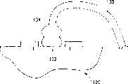
图1是传统的半导体封装260的剖面图。FIG. 1 is a cross-sectional view of a conventional semiconductor package 260 .
请参考图1,在基构架262上层叠下半导体芯片212和上半导体芯片200,且通过倒装片键合用在下半导体芯片212和上半导体芯片200之间设置的焊料凸点210互连。在下半导体芯片的边缘上放置的键合焊盘226通过引线264电连接于基构架的引线(未显示)。用密封树脂266密封上和下半导体芯片200和212、引线264和基构架262的一部分。Referring to FIG. 1 , a
图2至4是图示在传统的半导体封装内通过倒装片键合互连的下半导体芯片200和上半导体芯片212的剖面图。2 to 4 are cross-sectional views illustrating a
请参考图2,在上半导体芯片200的下面形成焊料凸点210。上和下半导体芯片200和212在由箭头A指示的方向上被放在一起。上半导体芯片200具有电路区202和键合焊盘208。下半导体芯片212具有电路区214和相应于上半导体芯片200的键合焊盘208的键合焊盘224。另外,在下半导体芯片212的边缘上分开形成用于导线键合的附加的键合焊盘226。Referring to FIG. 2 ,
图3是图示在传统的半导体封装中当在键合焊盘12上形成焊料凸点210时焊盘12的上层结构的剖面图。为了形成焊料凸点210,在通过其暴露键合焊盘12的钝化层14上附加形成如聚酰亚胺(polyimide)膜的绝缘层16。另外,应形成连接于键合焊盘12的凸点下冶金(Under Bump MetallurgyUBM)层18。附图标记10指示半导体芯片。3 is a cross-sectional view illustrating the upper structure of the
但是难以直接在一般构成键合焊盘12的铝层或铜层上形成焊料凸点210。为了解决该问题,UBM层18促进焊料凸点210和键合焊盘12的键合且防止焊料凸点的组分扩散入键合焊盘。UBM层18典型地是包括互连层、扩散阻挡层和浸润层的多金属层结构。However, it is difficult to directly form the
图4是在图1中的部分B的放大的剖面图。FIG. 4 is an enlarged sectional view of part B in FIG. 1 .
请参考图4,在上半导体芯片200和下半导体芯片212的键合焊盘12和12’上分别形成UBM层18和另一UBM层18’以实现使用焊料凸点210的倒装片键合。在下半导体芯片212上形成UBM层18’以促进固定于上半导体芯片200的焊料凸点210的键合和防止焊料凸点210的扩散进入下半导体芯片212的键合焊盘12’。Referring to FIG. 4, a
使用焊料凸点210的倒装片键合技术可以优选地用于互连,因为在引线键合(wiring bonding)期间可能对半导体芯片施加在预定水平以上的压力,特别当在半导体芯片的中心部分放置键合焊盘时。这样,压力可以损伤在键合焊盘的下层部分上放置的半导体芯片的电路区。The flip-chip bonding technique using
图5是图示图1所示的半导体封装的引线键合于下半导体芯片212(图1的部分C)的剖面图。对另一设置在下半导体芯片212上的键合焊盘226(图1)形成促进引线键合的金属层19。金属层可以由Ni/Au、Ni/Ag或Ti/Cu/Ni/Au的复合层组成。FIG. 5 is a cross-sectional view illustrating wire bonding of the semiconductor package shown in FIG. 1 to the lower semiconductor chip 212 (part C of FIG. 1 ). A metal layer 19 that facilitates wire bonding is formed to another bonding pad 226 ( FIG. 1 ) disposed on the
但是,在传统的半导体封装中,在下半导体芯片中附加形成UBM层,其非期望地延长了整体的SIP的制造工艺时间且增加了制造成本。However, in the conventional semiconductor package, the UBM layer is additionally formed in the lower semiconductor chip, which undesirably prolongs the manufacturing process time of the overall SIP and increases the manufacturing cost.
发明内容Contents of the invention
本发明尤其提供了具有用于倒装片键合的新结构的半导体封装,由此消除在不具有焊料凸点的半导体芯片上的UBM层的需求。本发明还提供了制造如封装中系统(SIP)的制造新半导体封装的方法。The present invention inter alia provides a semiconductor package with a new structure for flip-chip bonding, thereby eliminating the need for a UBM layer on a semiconductor chip without solder bumps. The present invention also provides a method of manufacturing a new semiconductor package such as a system in package (SIP).
根据本发明的一个方面,提供一种半导体封装,包括:According to one aspect of the present invention, a semiconductor package is provided, comprising:
基构架;base frame;
与所述基构架电连接的下半导体芯片,所述下半导体芯片具有在其顶表面上形成的第一键合焊盘;a lower semiconductor chip electrically connected to the base frame, the lower semiconductor chip having first bonding pads formed on its top surface;
在所述下半导体芯片之上的上半导体芯片,所述上半导体芯片具有在其底表面上形成的第三键合焊盘;an upper semiconductor chip above the lower semiconductor chip, the upper semiconductor chip having a third bonding pad formed on a bottom surface thereof;
第一导电凸点和第二导电凸点,共同地连接所述第一键合焊盘和所述第三键合焊盘。The first conductive bump and the second conductive bump are commonly connected to the first bonding pad and the third bonding pad.
根据本发明的另一方面,提供一种制造封装的方法包括:According to another aspect of the present invention, there is provided a method of manufacturing a package comprising:
提供基构架;Provide the basic framework;
提供下半导体芯片,所述下半导体芯片具有在所述下半导体芯片的中心部分上的第一键合焊盘和在所述下半导体芯片的周边部分上的第二键合焊盘;providing a lower semiconductor chip having a first bonding pad on a central portion of the lower semiconductor chip and a second bonding pad on a peripheral portion of the lower semiconductor chip;
在所述基构架上安装所述下半导体芯片;mounting the lower semiconductor chip on the base frame;
提供上半导体芯片,所述上半导体芯片具有相应于所述半导体芯片的第一键合焊盘的第三键合焊盘;和providing an upper semiconductor chip having third bond pads corresponding to the first bond pads of the semiconductor chip; and
通过一起使用第一导电凸点和第二导电凸点连接所述第三键合焊盘和所述第一键合焊盘,在所述下半导体芯片上安装所述上半导体芯片。The upper semiconductor chip is mounted on the lower semiconductor chip by connecting the third bonding pad and the first bonding pad using a first conductive bump and a second conductive bump together.
根据本发明的再一个方面,提供一种制造封装的方法,该方法包括:According to still another aspect of the present invention, there is provided a method of manufacturing a package, the method comprising:
制备下半导体芯片,所述下半导体芯片具有在其中心部分的第一键合焊盘,和上半导体芯片,所述上半导体芯片具有相应于所述下半导体芯片的第一键合焊盘的第三键合焊盘;A lower semiconductor chip having a first bonding pad at a central portion thereof, and an upper semiconductor chip having a first bonding pad corresponding to the first bonding pad of the lower semiconductor chip are prepared. Three bonding pads;
一起使用第一导电凸点和第二导电凸点,电连接所述下半导体芯片的第一键合焊盘与所述上半导体芯片的第三键合焊盘;和using together a first conductive bump and a second conductive bump to electrically connect a first bonding pad of the lower semiconductor chip with a third bonding pad of the upper semiconductor chip; and
在所述基构架上安装所述电连接的上半导体芯片和下半导体芯片。The electrically connected upper and lower semiconductor chips are mounted on the base frame.
在一实施例中,半导体封装包括基构架和电连接于基构架的下半导体芯片。下半导体芯片具有在其顶表面上形成的第一键合焊盘。封装还包括放在下半导体芯片上的上半导体芯片。上半导体芯片具有在其底表面上形成的第三键合焊盘。封装包括共同地连接第一键合焊盘和第三键合焊盘的第一导电凸点和第二导电凸点。In one embodiment, a semiconductor package includes a base frame and a lower semiconductor chip electrically connected to the base frame. The lower semiconductor chip has first bonding pads formed on its top surface. The package also includes an upper semiconductor chip placed on the lower semiconductor chip. The upper semiconductor chip has third bonding pads formed on its bottom surface. The package includes first and second conductive bumps commonly connecting the first bonding pad and the third bonding pad.
附图说明Description of drawings
通过参考附图详细描述本发明的示范性实施例,本发明的上述和其它特征和优点将变得显而易见,其中:The above and other features and advantages of the present invention will become apparent by describing in detail exemplary embodiments of the present invention with reference to the accompanying drawings, in which:
图1是传统的半导体封装的剖面图;1 is a cross-sectional view of a conventional semiconductor package;
图2至图4是图示在图1中所示的传统的半导体封装中通过倒装片键合互连的下半导体芯片和上半导体芯片的剖面图;2 to 4 are cross-sectional views illustrating a lower semiconductor chip and an upper semiconductor chip interconnected by flip-chip bonding in the conventional semiconductor package shown in FIG. 1;
图5是图示在图1中所示的传统的半导体封装中引线键合于下半导体芯片的剖面图;5 is a cross-sectional view illustrating wire bonding to a lower semiconductor chip in the conventional semiconductor package shown in FIG. 1;
图6是图示本发明的实施例的半导体封装的剖面图;6 is a cross-sectional view illustrating a semiconductor package of an embodiment of the present invention;
图7是图示在图6中所示的半导体封装中通过倒装片互连的下半导体芯片和上半导体芯片的剖面图;7 is a cross-sectional view illustrating a lower semiconductor chip and an upper semiconductor chip interconnected by flip-chip in the semiconductor package shown in FIG. 6;
图8是图示在图6中所示的半导体封装中引线键合于下半导体芯片的剖面图;8 is a cross-sectional view illustrating wire bonding to a lower semiconductor chip in the semiconductor package shown in FIG. 6;
图9是图示本发明的另一实施例的半导体封装的剖面图;9 is a cross-sectional view illustrating a semiconductor package of another embodiment of the present invention;
图10是图示在图9中所示的半导体封装中通过倒装片互连的下半导体芯片和上半导体芯片的剖面图;10 is a cross-sectional view illustrating a lower semiconductor chip and an upper semiconductor chip interconnected by flip-chip in the semiconductor package shown in FIG. 9;
图11是图示在图9中所示的半导体封装中引线键合于下半导体芯片的剖面图;11 is a cross-sectional view illustrating wire bonding to a lower semiconductor chip in the semiconductor package shown in FIG. 9;
图12是图示本发明的再一实施例的半导体封装的剖面图;12 is a cross-sectional view illustrating a semiconductor package of still another embodiment of the present invention;
图13是图示在图12中所示的半导体封装中通过倒装片互连的下半导体芯片和上半导体芯片的剖面图;13 is a cross-sectional view illustrating a lower semiconductor chip and an upper semiconductor chip interconnected by flip chip in the semiconductor package shown in FIG. 12;
图14是图示在图12中所示的半导体封装中引线键合于下半导体芯片的剖面图;14 is a cross-sectional view illustrating wire bonding to a lower semiconductor chip in the semiconductor package shown in FIG. 12;
图15是图示本发明的再一实施例的半导体封装的剖面图;15 is a cross-sectional view illustrating a semiconductor package of still another embodiment of the present invention;
图16是图示在图15中所示的半导体封装中通过倒装片互连的下半导体芯片和上半导体芯片的剖面图;16 is a cross-sectional view illustrating a lower semiconductor chip and an upper semiconductor chip interconnected by flip chip in the semiconductor package shown in FIG. 15;
图17是图示在图15中所示的半导体封装中引线键合于下半导体芯片的剖面图;17 is a cross-sectional view illustrating wire bonding to a lower semiconductor chip in the semiconductor package shown in FIG. 15;
图18是图示本发明的实施例的半导体封装的基构架、下半导体芯片和上半导体芯片的结构的平面图;和18 is a plan view illustrating structures of a base frame, a lower semiconductor chip, and an upper semiconductor chip of a semiconductor package according to an embodiment of the present invention; and
图19是图示本发明的实施例的半导体封装的剖面图。19 is a cross-sectional view illustrating a semiconductor package of an embodiment of the present invention.
具体实施方式Detailed ways
现在将参考附图更加全面地描述本发明。但是本发明可以以不同的形式具体表达且不应解释为限于在这里阐述的实施例;而是提供这些实施例以使本公开充分和完整,且全面地对本领域的技术人员传达本发明的构思。The present invention will now be described more fully with reference to the accompanying drawings. This invention may, however, be embodied in different forms and should not be construed as limited to the embodiments set forth herein; rather, these embodiments are provided so that this disclosure will be thorough and complete, and will fully convey the concept of the invention to those skilled in the art. .
请参考图6,本发明的实施例的半导体封装,例如SIP100A,包括基构架110。通过例如粘合剂160将下半导体芯片固定于基构架110的芯片焊盘。在下半导体芯片120的上表面的中心部分上形成第一键合焊盘122,用于倒装片互连,且在下半导体芯片120的上表面的边缘部分或周边区域上形成第二键合焊盘132。另外,下半导体芯片120包括导电凸点124,例如金凸点,其形成在第一键合焊盘122上。导电凸点124可以形成为按扣(stud)状或其它合适的结构用于互连。Referring to FIG. 6 , the semiconductor package of the embodiment of the present invention, such as SIP100A, includes a
SIP100A可以包括电连接下半导体芯片120的第二键合焊盘132至基构架110的引线130。而且,在下半导体芯片120上安装的上半导体芯片140包括另一导电凸点144,例如,设置在第三键合焊盘142上的焊料凸点,以连接于在下半导体芯片120的第一键合焊盘122上的金凸点124。密封树脂150可以紧密地密封一部分基构架110、引线130、下半导体芯片120和上半导体芯片140。The SIP 100A may include a lead 130 electrically connecting the
可以用密封树脂150,或未充满材料170,如环氧,填充在互连的下半导体芯片120和上半导体芯片140之间的空间以提供互连的可靠性。A space between the interconnected
在半导体组装工艺期间使用引线键合设备可以在第一键合焊盘122上容易地形成金凸点124。金凸点124消除了在第二键合焊盘132上的UBM层的需求。即,尽管采用传统的第一和第二键合焊盘122和132,但是不需要在下半导体芯片120上形成UBM层。由此,可以缩短整体的制造工艺的时间且降低制造成本。The
图7是图示SIP中使用倒装片技术下半导体芯片120和上半导体芯片140的互连的剖面图。图8是图示引线130键合于下半导体芯片120的剖面图。FIG. 7 is a cross-sectional view illustrating the interconnection of the
请参考图7和图8,本发明的该实施例的SIP100A中,通过连接按扣状金凸点124至焊料凸点144可以实现倒装片键合。具有焊料凸点144的上半导体芯片140经受UBM处理,其中形成绝缘层146和UBM层148。但是,在具有金凸点124的下半导体芯片120上不需UBM处理。而且,连接下半导体芯片120与基构架110的引线130直接连接于构成第二键合焊盘132的铝。引线130可以由Au、Ag或Cu组成。Please refer to FIG. 7 and FIG. 8 , in the SIP 100A of this embodiment of the present invention, flip-chip bonding can be realized by connecting the snap-shaped gold bumps 124 to the solder bumps 144 . The
请参考图6,现在将描述本发明的实施例的制造SIP110A的方法。Referring to FIG. 6 , a method of manufacturing a SIP 110A according to an embodiment of the present invention will now be described.
柔性印刷电路板(PCB)或刚性PCB可以用作基构架110。一般用于球栅阵列(BGA)的基构架可以用作基构架110。然后,优选地使用如粘接带或环氧的粘接剂160,在基构架110上安装下半导体芯片120。在下半导体芯片120的中心部分上形成适合倒装片键合的第一键合焊盘122,且在下半导体芯片120的边缘部分上形成用于引线键合的第二键合焊盘132。在第一键合焊盘122上形成金凸点124。下半导体芯片120可以用为微处理器、LSI或逻辑器件。A flexible printed circuit board (PCB) or a rigid PCB may be used as the
金凸点124可以在晶片制造工艺中形成,或者在基构架110上安装下半导体芯片120之后的半导体芯片状态中形成。The gold bumps 124 may be formed in a wafer manufacturing process, or in a semiconductor chip state after the
随后,通过如键合引线130的电连接装置将下半导体芯片120的第二键合焊盘132电连接于基构架110的键合指(图18的标号112)。引线键合可以在装入上半导体芯片140之后进行。Subsequently, the
制备具有相应于下半导体芯片120的第一键合焊盘122的第三键合焊盘143的上半导体芯片140和在第三键合焊盘142上的焊料凸点144。上半导体芯片140的第三键合焊盘142形成有UBM层148和绝缘层146,以促进焊料凸点144的互连以及防止扩散。An
然后,通过倒装片键合将下半导体芯片120的金凸点124设置为与上半导体芯片140的焊料凸点144接触,由此在下半导体芯片120上安装上半导体芯片140。在安装上半导体芯片140之后,在下半导体芯片120和上半导体芯片140之间填充如液态环氧的未充满材料以改进互连的可靠性,且固化形成未充满材料170。Then, the gold bumps 124 of the
因此,可以通过密封树脂150密封一部分基构架110、引线130以及下和上半导体芯片120和140。最后,将焊料球153固定于设置在基构架110下的焊料球焊盘(未显示),且进行单独地分离以矩阵形成制造的SIP100A的单一化工艺。Accordingly, a portion of the
请重新参考图6,现在将描述制造SIP的另一方法。这里,首先互连下半导体芯片120和上半导体芯片140,且然后在基构架110上安装互连的结构。Referring back to Figure 6, another method of fabricating a SIP will now be described. Here, the
更具体地,以第一键合焊盘122在中心部分上和第二键合焊盘132在周边部分上形成下半导体芯片120。以相应于第一键合焊盘122的第三键合焊盘142在其上形成上半导体芯片140。在第一键合焊盘122上形成按扣状金凸点124,且在第三键合焊盘142上形成焊料凸点144。More specifically, the
下半导体芯片120的金凸点124和上半导体芯片140的焊料凸点144设置为互相接触。然后,使用粘接剂160在基构架110上安装共同互连的下半导体芯片120和上半导体芯片140。在紧接着互连下半导体芯片120与上半导体芯片140之后,或在紧接着基构架110上安装互连的下半导体芯片120和上半导体芯片140之后,下半导体芯片120和上半导体芯片140可以经受焊剂清除。The gold bumps 124 of the
用液态环氧填充下半导体芯片120和上半导体芯片140之间的空间,环氧被固化以形成未充满材料170以改善互连的可靠性。The space between the
之后,通过引线130电连接下半导体芯片的第二键合焊盘132和基构架110。使用密封树脂150可以密封基构架110、引线130以及下和上半导体芯片120和140。最后,将焊料球152固定于设置在基构架110下的焊料球焊盘(未显示),且进行单独分离以矩阵形成制造的SIP100A的单一化工艺。Afterwards, the
现在将描述具有施加于上半导体芯片的按扣状的金凸点的另一实施例。图9是图示本发明的该实施例的SIP的剖面图。Another embodiment with snap-shaped gold bumps applied to the upper semiconductor chip will now be described. Fig. 9 is a cross-sectional view illustrating the SIP of this embodiment of the present invention.
请参考图9,SIP100B包括其上可以安装半导体芯片的基构架110。使用粘接剂160将下半导体芯片120固定于基构架芯片焊盘,且在下半导体芯片120的中心部分上形成用于倒装片键合的第一键合焊盘122和在下半导体芯片120的边缘部分上形成第二键合焊盘132。在下半导体芯片120的第一键合焊盘122上形成焊料凸点124。Referring to FIG. 9, the SIP 100B includes a
SIP100B还包括电连接下半导体芯片120的第二键合焊盘132至基构架110的引线130,和在下半导体芯片120上层叠的上半导体芯片140。上半导体芯片140的第三键合焊盘142形成有金凸点144,以与下半导体芯片120的互连凸点124接触。The SIP 100B also includes
SIP100B还包括紧密地密封一部分基构架110、引线130、下半导体芯片120和上半导体芯片140。在下半导体芯片120与上半导体芯片140之间形成未充满材料170。以按扣状金凸点144形成的上半导体芯片140的第三键合焊盘142消除了UBM处理的需求。The SIP 100B also includes tightly sealing a portion of the
图10是图示本发明的实施例的SIP中下半导体芯片120和上半导体芯片140的倒装片键合剖面图。图11是图示导线130键合于下半导体芯片120的剖面图。10 is a cross-sectional view illustrating flip-chip bonding of a
请参考图10和图11,通过上半导体芯片140的按扣状金凸点144与在下半导体芯片120上形成的焊料凸点124接触获得倒装片键合。具有焊料凸点124的下半导体芯片120经受UBM处理。即,下半导体芯片120包括绝缘层126和UBM层128。Referring to FIGS. 10 and 11 , flip-chip bonding is achieved by contacting the snap-shaped gold bumps 144 of the
在UBM层128上形成金属层129以帮助促进引线键合工艺。金属层129可由Ni/Au、Ni/Ag或Ni/Pd的复合层组成。引线130可以是Au、Ag和Cu。
此后,将参考图9描述本发明的该实施例的制造SIP100B的方法。Hereinafter, the method of manufacturing the SIP 100B of this embodiment of the present invention will be described with reference to FIG. 9 .
柔性PCB或刚性PCB可以用作基构架110。然后,使用如粘接带或环氧的粘接剂160,下半导体芯片120固定于基构架110。在下半导体芯片120的中心部分上形成适合倒装片键合的第一键合焊盘122,且在下半导体芯片120的边缘部分上形成用于引线键合的第二键合焊盘132。在第一键合焊盘122上形成焊料凸点124。下半导体芯片120可以是微处理器、LSI或逻辑器件而上半导体芯片140可以是电容器器件。A flexible PCB or a rigid PCB can be used as the
随后,通过引线键合将下半导体芯片120的第二键合焊盘132电连接于基构架110的键合指112(见图18)。该工艺也可以在装入上半导体芯片140之后进行。Subsequently, the
然后,制备具有相应于下半导体芯片120的第一键合焊盘122的第三键合焊盘143的上半导体芯片140和在第三键合焊盘142上的金凸点144。可以在晶片制造工艺中形成金凸点144。上半导体芯片140的第三键合焊盘142可以不包括UBM层。Then, the
然后,通过倒装片键合互连下半导体芯片120的焊料凸点124与上半导体芯片140的金凸点144,由此在下半导体芯片120上安装上半导体芯片140。在安装上半导体芯片140之后,在下半导体芯片120和上半导体芯片140之间填充如液态环氧,且固化形成未充满材料170的以改进互连的可靠性。Then, the solder bumps 124 of the
通过密封树脂150密封基构架110、引线130以及下和上半导体芯片120和140。最后,将焊料球152固定于设置在基构架110下层部分,且单一化以矩阵形成制造的SIP100B。The
现在将参考图9描述本发明的另一实施例的制造SIP100B的方法。这时,首先互连下半导体芯片120和上半导体芯片140,且然后在基构架110上装入结果的结构。A method of manufacturing a SIP 100B according to another embodiment of the present invention will now be described with reference to FIG. 9 . At this time, the
更具体地,制备下半导体芯片120和上半导体芯片140。这时,下半导体芯片120具有在中心部分上的第一键合焊盘122和在周边部分的上第二键合焊盘132。上半导体芯片140具有以相应于第一键合焊盘122的第三键合焊盘142。在第一键合焊盘122上形成焊料凸点124,且在第三键合焊盘142上形成按扣状金凸点144。More specifically, the
下半导体芯片120的焊料凸点124和上半导体芯片140的金凸点144设置为互相接触。然后,使用粘接剂160在基构架110上安装共同互连的下半导体芯片120和上半导体芯片140。在紧接着互连之后或在紧接着基构架110上安装已经互连的下半导体芯片120和上半导体芯片140之后,下半导体芯片120和上半导体芯片140可以经受焊剂清除。The solder bumps 124 of the
为了改善互连的可靠性,在下半导体芯片120和上半导体芯片140之间填充液态环氧,其然后被固化以形成未充满材料170。In order to improve the reliability of the interconnection, liquid epoxy is filled between the
之后,引线130电连接于包括金属层129的第二键合焊盘132用于促进对基构架110的引线键合。使用密封树脂150或其它适合的封装剂密封或封装基构架110、引线130以及下和上半导体芯片120和140。最后,将焊料球152固定于设置在基构架110的下层部分,且以矩阵形成制造的SIP100B被单一化,即,单独地分离。Afterwards, the
现在将描述具有施加于下半导体芯片的电镀的金凸点的再一实施例。A further embodiment of gold bumps with electroplating applied to the lower semiconductor chip will now be described.
图12是图示本发明的本方面的该实施例的SIP的剖面图。图13是图示下半导体芯片120和上半导体芯片140的倒装片键合的剖面图。图14是图示导线键合于下半导体芯片120的剖面图。Figure 12 is a cross-sectional view of a SIP illustrating this embodiment of this aspect of the invention. FIG. 13 is a cross-sectional view illustrating flip-chip bonding of the
请参考图12、13、14,本发明的该实施例的SIP100C的结构和制造方法与上述的第一实施例相似。为了简明因此将省略相同部分的描述。Please refer to Figures 12, 13, and 14, the structure and manufacturing method of the SIP100C of this embodiment of the present invention are similar to those of the above-mentioned first embodiment. Descriptions of the same parts will therefore be omitted for brevity.
相对于所述的第一实施例,在第三实施例中的下半导体芯片120上设置的金凸点125由电镀(electroplating)形成。在下半导体芯片120的边缘上的第二键合焊盘132上以及下半导体芯片120的第一键合焊盘122上形成金凸点125。因此,在设置在第二键合焊盘132上的金凸点125上进行连接下半导体芯片120和基构架110的引线键合。因此,引线键合的金凸点134具有两个层叠的球键合的形状。With respect to the first embodiment described above, the gold bumps 125 provided on the
如所述的第一实施例,在上半导体芯片140上进行UBM处理,但不需对下半导体芯片120进行UBM处理。因此,简化了工艺且降低了制造成本。As in the first embodiment described, the UBM process is performed on the
现在将描述具有施加于上半导体芯片140的电镀金凸点的再一实施例。A further embodiment with electroplated gold bumps applied to the
图15是图示本发明的本方面的该实施例的SIP的剖面图。图16是图示下半导体芯片120和上半导体芯片140的倒装片键合的剖面图。图17是图示导线键合于下半导体芯片120的剖面图。Figure 15 is a cross-sectional view of a SIP illustrating this embodiment of the present aspect of the invention. FIG. 16 is a cross-sectional view illustrating flip-chip bonding of the
请参考图15、16、17,本发明的该实施例的SIP100C的结构和制造方法与图9相关描述的实施例相似。为了简明因此将省略相同部分的描述。Please refer to FIGS. 15 , 16 , and 17 . The structure and manufacturing method of the SIP100C of this embodiment of the present invention are similar to the embodiment described in relation to FIG. 9 . Descriptions of the same parts will therefore be omitted for brevity.
相对于图9所示的实施例,上半导体芯片140的第三键合焊盘142上设置的金凸点144由电镀形成。如图9的实施例,下半导体芯片120经受UBM处理,对上半导体芯片140未进行UBM处理。因此,简化了工艺且降低了制造成本。Compared with the embodiment shown in FIG. 9 , the gold bumps 144 disposed on the
图18是图示本发明的实施例的半导体封装的基构架、下半导体芯片和上半导体芯片的结构的平面图。18 is a plan view illustrating structures of a base frame, a lower semiconductor chip, and an upper semiconductor chip of the semiconductor package of the embodiment of the present invention.
请参考图18,在基构架110上安装下半导体芯片120。在下半导体芯片120上安装上半导体芯片140。通过引线130在下半导体芯片120上设置的第二键合焊盘132电连接于在基构架110上的引线指针112。本发明的实施例的下和上半导体芯片120和140的倒装片互连150的材料和结构由焊料凸点和金凸点接触表征。Referring to FIG. 18 , a
上半导体芯片140可以是用于改善半导体器件的噪音特性的无源器件。无源器件的制造方法是众所周知的,且为了简明省略了在美国专利申请序列号9/386,660(由Lucent Technology Co.Ltd申请于1999年8月31日)公开的这样的方法的例子的详细说明。The
而且,在下半导体芯片120的中心部分上的第一键合焊盘122可以通过内部电路线121连接至第二键合焊盘132。可以在用于形成晶片级封装(WIP)的晶片制造工艺期间或之后形成连接第一和第二键合焊盘122和132的内部电路线121。Also, the
因此,作为电容器的上半导体芯片140的电源和接地端子可以通过第一键合焊盘122连接至第二键合焊盘132。而且,可以通过引线130将第二键合焊盘132连接至基构架110的键合指针112。键合指针112可以通过焊料球(未显示)外部地连接固定于基构架110的下层表面。Accordingly, power and ground terminals of the
因此,可以邻近于作为微处理器、LSI器件或逻辑器件的下半导体芯片120装入作为电容器的上半导体芯片140,由此具体化能够改善下半导体芯片120的噪音特性的SIP。Accordingly, the
在再一实施例中,可以使用引线构架作为基构架。In yet another embodiment, a lead frame may be used as the base frame.
图19是本发明的一实施例的SIP的剖面图。在前述的实施例中,基构架110可以是柔性PCB或刚性PCB。但是,SIP100E包括替代在上述的实施例中包括的PCB的引线构架110’。引线构架110’包括芯片焊盘114和引线112。依据引线构架110’的形状,SIP100E可以使用不同的封装,如薄小外形封装(Thin Small Outline Package TSOP)、薄四方平封装(Thin Quad FlatPackage TQFP)和四方薄无引线封装(Quad Flat No-lead Package QFN)。在该情况中,在封装或密封之后,从密封树脂150外部地暴露的引线112可以被引线栅修整(lead bar trimmed)、引线镀或引线形成。另外,本发明可应用于针栅阵列(PGA)封装,其中取代使用焊料球针栅与基构架110的下表面连接。Fig. 19 is a cross-sectional view of a SIP according to an embodiment of the present invention. In the foregoing embodiments, the
如上所述,用本发明的实施例,不需要在具有金凸点的半导体芯片上进行UBM处理。因此,可以降低制造成本,且可以简化制造工艺。As described above, with embodiments of the present invention, there is no need for UBM processing on semiconductor chips with gold bumps. Therefore, the manufacturing cost can be reduced, and the manufacturing process can be simplified.
当参考本发明的示范性实施例具体显示和描述本发明时,本领域的技术人员会理解在不背离由所附的权利要求界定的本发明的精神和范围内,可以在其内作不同的形式和细节的更动。While the invention has been particularly shown and described with reference to exemplary embodiments thereof, those skilled in the art will appreciate that changes may be made therein without departing from the spirit and scope of the invention as defined by the appended claims. Changes in form and detail.
本申请要求于2004年4月30日申请的韩国专利申请第10-2004-0030468的优先权,其全部内容引入作为参考。This application claims priority from Korean Patent Application No. 10-2004-0030468 filed on Apr. 30, 2004, the entire contents of which are incorporated by reference.
Claims (57)
Translated fromChineseApplications Claiming Priority (2)
| Application Number | Priority Date | Filing Date | Title |
|---|---|---|---|
| KR1020040030468AKR100604848B1 (en) | 2004-04-30 | 2004-04-30 | System-in-package with solder bump and gold bump junction and method of manufacturing the same |
| KR30468/04 | 2004-04-30 |
Publications (1)
| Publication Number | Publication Date |
|---|---|
| CN1700458Atrue CN1700458A (en) | 2005-11-23 |
Family
ID=35186218
Family Applications (1)
| Application Number | Title | Priority Date | Filing Date |
|---|---|---|---|
| CNA2005100667995APendingCN1700458A (en) | 2004-04-30 | 2005-04-29 | Semiconductor package with first and second conductive bumps and manufacturing method thereof |
Country Status (5)
| Country | Link |
|---|---|
| US (1) | US20050242426A1 (en) |
| JP (1) | JP2005317975A (en) |
| KR (1) | KR100604848B1 (en) |
| CN (1) | CN1700458A (en) |
| DE (1) | DE102005020972A1 (en) |
Cited By (5)
| Publication number | Priority date | Publication date | Assignee | Title |
|---|---|---|---|---|
| US8148819B2 (en) | 2008-05-19 | 2012-04-03 | Sharp Kabushiki Kaisha | Semiconductor device, method for mounting semiconductor device, and mounting structure of semiconductor device |
| CN102412208A (en)* | 2010-09-21 | 2012-04-11 | 矽品精密工业股份有限公司 | Chip size package and method for making the same |
| CN102769009A (en)* | 2011-05-04 | 2012-11-07 | 三星半导体(中国)研究开发有限公司 | semiconductor package |
| CN103379736A (en)* | 2012-04-13 | 2013-10-30 | 广达电脑股份有限公司 | System-in-package assembly, printed circuit board assembly and manufacturing method thereof |
| CN110323198A (en)* | 2019-07-26 | 2019-10-11 | 广东气派科技有限公司 | Contactless upper lower chip packaging structure and its packaging method |
Families Citing this family (13)
| Publication number | Priority date | Publication date | Assignee | Title |
|---|---|---|---|---|
| US9299634B2 (en)* | 2006-05-16 | 2016-03-29 | Broadcom Corporation | Method and apparatus for cooling semiconductor device hot blocks and large scale integrated circuit (IC) using integrated interposer for IC packages |
| US9013035B2 (en)* | 2006-06-20 | 2015-04-21 | Broadcom Corporation | Thermal improvement for hotspots on dies in integrated circuit packages |
| DE102006034679A1 (en)* | 2006-07-24 | 2008-01-31 | Infineon Technologies Ag | Semiconductor module with power semiconductor chip and passive component and method for producing the same |
| JP5338029B2 (en)* | 2007-01-26 | 2013-11-13 | 日亜化学工業株式会社 | Semiconductor laser device, semiconductor laser device and manufacturing method thereof |
| TWI364793B (en)* | 2007-05-08 | 2012-05-21 | Mutual Pak Technology Co Ltd | Package structure for integrated circuit device and method of the same |
| JP5331610B2 (en)* | 2008-12-03 | 2013-10-30 | ルネサスエレクトロニクス株式会社 | Semiconductor integrated circuit device |
| CN102691921A (en)* | 2011-03-22 | 2012-09-26 | 展晶科技(深圳)有限公司 | Light-emitting diode light bar and method for manufacturing same |
| KR20140070057A (en)* | 2012-11-30 | 2014-06-10 | 삼성전자주식회사 | Semiconductor Packages and Methods of Fabricating the Same |
| KR102190382B1 (en) | 2012-12-20 | 2020-12-11 | 삼성전자주식회사 | Semiconductor package |
| KR102053349B1 (en) | 2013-05-16 | 2019-12-06 | 삼성전자주식회사 | Semiconductor package |
| KR101504011B1 (en) | 2013-06-26 | 2015-03-18 | (주)인터플렉스 | Complex integrated circuit device package manufacturing method |
| JP6386746B2 (en) | 2014-02-26 | 2018-09-05 | 株式会社ジェイデバイス | Semiconductor device |
| CN104157617B (en)* | 2014-07-29 | 2017-11-17 | 华为技术有限公司 | Chip integrated module, chip packaging structure and chip integration method |
Family Cites Families (12)
| Publication number | Priority date | Publication date | Assignee | Title |
|---|---|---|---|---|
| US5211875A (en)* | 1991-06-27 | 1993-05-18 | W. R. Grace & Co.-Conn. | Methods and compositions for oxygen scavenging |
| TW520816U (en)* | 1995-04-24 | 2003-02-11 | Matsushita Electric Industrial Co Ltd | Semiconductor device |
| US5889326A (en)* | 1996-02-27 | 1999-03-30 | Nec Corporation | Structure for bonding semiconductor device to substrate |
| US6057598A (en)* | 1997-01-31 | 2000-05-02 | Vlsi Technology, Inc. | Face on face flip chip integration |
| US6413797B2 (en)* | 1997-10-09 | 2002-07-02 | Rohm Co., Ltd. | Semiconductor device and method for making the same |
| US6369451B2 (en)* | 1998-01-13 | 2002-04-09 | Paul T. Lin | Solder balls and columns with stratified underfills on substrate for flip chip joining |
| SG93192A1 (en)* | 1999-01-28 | 2002-12-17 | United Microelectronics Corp | Face-to-face multi chip package |
| US6410415B1 (en)* | 1999-03-23 | 2002-06-25 | Polymer Flip Chip Corporation | Flip chip mounting technique |
| JP3597754B2 (en)* | 2000-04-24 | 2004-12-08 | Necエレクトロニクス株式会社 | Semiconductor device and manufacturing method thereof |
| US7242099B2 (en)* | 2001-03-05 | 2007-07-10 | Megica Corporation | Chip package with multiple chips connected by bumps |
| US20020127747A1 (en)* | 2001-03-08 | 2002-09-12 | Motorola, Inc. | Lithography method and apparatus with simplified reticles |
| TW529141B (en)* | 2002-01-07 | 2003-04-21 | Advanced Semiconductor Eng | Stacking type multi-chip package and its manufacturing process |
- 2004
- 2004-04-30KRKR1020040030468Apatent/KR100604848B1/ennot_activeExpired - Fee Related
- 2005
- 2005-04-19USUS11/110,443patent/US20050242426A1/ennot_activeAbandoned
- 2005-04-27JPJP2005130543Apatent/JP2005317975A/ennot_activeWithdrawn
- 2005-04-29DEDE102005020972Apatent/DE102005020972A1/ennot_activeCeased
- 2005-04-29CNCNA2005100667995Apatent/CN1700458A/enactivePending
Cited By (7)
| Publication number | Priority date | Publication date | Assignee | Title |
|---|---|---|---|---|
| US8148819B2 (en) | 2008-05-19 | 2012-04-03 | Sharp Kabushiki Kaisha | Semiconductor device, method for mounting semiconductor device, and mounting structure of semiconductor device |
| CN102412208A (en)* | 2010-09-21 | 2012-04-11 | 矽品精密工业股份有限公司 | Chip size package and method for making the same |
| CN102412208B (en)* | 2010-09-21 | 2014-08-13 | 矽品精密工业股份有限公司 | Chip size package and method for making the same |
| CN102769009A (en)* | 2011-05-04 | 2012-11-07 | 三星半导体(中国)研究开发有限公司 | semiconductor package |
| CN103379736A (en)* | 2012-04-13 | 2013-10-30 | 广达电脑股份有限公司 | System-in-package assembly, printed circuit board assembly and manufacturing method thereof |
| CN110323198A (en)* | 2019-07-26 | 2019-10-11 | 广东气派科技有限公司 | Contactless upper lower chip packaging structure and its packaging method |
| CN110323198B (en)* | 2019-07-26 | 2024-04-26 | 广东气派科技有限公司 | Non-contact type upper and lower chip packaging structure and packaging method thereof |
Also Published As
| Publication number | Publication date |
|---|---|
| KR100604848B1 (en) | 2006-07-31 |
| US20050242426A1 (en) | 2005-11-03 |
| DE102005020972A1 (en) | 2006-01-05 |
| KR20050105361A (en) | 2005-11-04 |
| JP2005317975A (en) | 2005-11-10 |
Similar Documents
| Publication | Publication Date | Title |
|---|---|---|
| CN1271712C (en) | Semiconductor device with heat sink exposed from sealing resin | |
| CN1283004C (en) | Semiconductor device and its manufacturing method, circuit base plate and electronic machine | |
| CN1700458A (en) | Semiconductor package with first and second conductive bumps and manufacturing method thereof | |
| CN1368761A (en) | Semiconductor device | |
| US20070254406A1 (en) | Method for manufacturing stacked package structure | |
| CN1292475C (en) | Semiconductor package and manufacturing method thereof | |
| US20110115085A1 (en) | Semiconductor device and method of fabricating the same | |
| CN1264923A (en) | Semiconductor device and its mfg. method | |
| CN1185698C (en) | Semiconductor device and manufacture method thereof, circuit board and electronic apparatus | |
| CN1459855A (en) | Semiconductor device and mfg. method thereof | |
| JP2002252303A (en) | Flip-chip semiconductor device for molded chip-scale package, and assembling method therefor | |
| CN1452245A (en) | Semiconductor device and method for manufacturing the same | |
| CN1750257A (en) | Component, package, substrate structure and package method of pin-on-solder pad package | |
| CN1512580A (en) | Semiconductor device and manufacturing method thereof | |
| JP2007088453A (en) | Method for manufacturing a stacked die package | |
| US9324636B2 (en) | Resin-sealed semiconductor device and associated wiring and support structure | |
| CN1711639A (en) | Folded flexible multi-chip power package without bond wires | |
| CN1819190A (en) | Semiconductor device | |
| CN100524741C (en) | Stacked package structure | |
| CN1519930A (en) | Semiconductor devices, electronic devices, their manufacturing methods, and electronic instruments | |
| CN100463152C (en) | Method for manufacturing direct chip connection device and structure | |
| TWI501371B (en) | A wiring member for a semiconductor device, a composite wiring member for a semiconductor device, and a resin-sealed type semiconductor device | |
| CN1906757A (en) | Semiconductor device | |
| CN101064259A (en) | Semiconductor package and its chip carrying structure and manufacturing method | |
| CN101047160A (en) | Semiconductor wiring packaging structure and connection method with integrated circuit |
Legal Events
| Date | Code | Title | Description |
|---|---|---|---|
| C06 | Publication | ||
| PB01 | Publication | ||
| C10 | Entry into substantive examination | ||
| SE01 | Entry into force of request for substantive examination | ||
| C02 | Deemed withdrawal of patent application after publication (patent law 2001) | ||
| WD01 | Invention patent application deemed withdrawn after publication | Open date:20051123 |