CN1694749A - A component that guides a toy car - Google Patents
A component that guides a toy carDownload PDFInfo
- Publication number
- CN1694749A CN1694749ACN03825044.6ACN03825044ACN1694749ACN 1694749 ACN1694749 ACN 1694749ACN 03825044 ACN03825044 ACN 03825044ACN 1694749 ACN1694749 ACN 1694749A
- Authority
- CN
- China
- Prior art keywords
- runway
- connector
- spare
- parts
- assembly
- Prior art date
- Legal status (The legal status is an assumption and is not a legal conclusion. Google has not performed a legal analysis and makes no representation as to the accuracy of the status listed.)
- Pending
Links
Images


Classifications
- A—HUMAN NECESSITIES
- A63—SPORTS; GAMES; AMUSEMENTS
- A63H—TOYS, e.g. TOPS, DOLLS, HOOPS OR BUILDING BLOCKS
- A63H18/00—Highways or trackways for toys; Propulsion by special interaction between vehicle and track
- A63H18/02—Construction or arrangement of the trackway
- A—HUMAN NECESSITIES
- A63—SPORTS; GAMES; AMUSEMENTS
- A63H—TOYS, e.g. TOPS, DOLLS, HOOPS OR BUILDING BLOCKS
- A63H18/00—Highways or trackways for toys; Propulsion by special interaction between vehicle and track
Landscapes
- Toys (AREA)
Abstract
Description
Translated fromChinese技术领域technical field
本发明涉及一种具有教育功能的玩具,具体地和非排它地,涉及一种引导玩具车的组件。The present invention relates to a toy with an educational function, in particular and not exclusively, to an assembly for guiding a toy vehicle.
发明内容Contents of the invention
本发明的主要目的之一是向大多数玩具车系统提供的跑道结构形式进行改进。One of the main objects of the present invention is to provide an improvement to the race track configuration provided by most toy vehicle systems.
根据本发明的第一方面,提供了一种引导玩具车的组件,该组件包括多个大致直线的跑道件,以及与所述跑道件分开形成的多个连接件,各跑道件具有三条或更多条边,各边具有成形凹部,用于接受和保持连接件的端部,在使用中,连接件通过使相邻边的端部对齐,可释放地保持邻接的跑道件。According to a first aspect of the present invention there is provided an assembly for guiding a toy vehicle, the assembly comprising a plurality of generally rectilinear track pieces, and a plurality of connecting pieces formed separately from the track pieces, each track piece having three or more A plurality of sides, each having a shaped recess for receiving and retaining an end of a connector, which, in use, releasably retains an adjoining track member by aligning the ends of adjacent sides.
这种已知的一般类型跑道件各自具有与跑道件一体形成的分合拼板型的“凸”“凹”连接组合。这限制了部件相互连接方位的数量,而上述根据本发明的组件并不限于这种方式。This known general type of track elements each has a "male" and "female" connection combination of split panel type integrally formed with the track element. This limits the number of interconnection orientations of the components, and the assembly according to the invention described above is not limited in this way.
各跑道件可设有单个形成跑道结构,如槽、轨等,或者各跑道件可设有两种或多种形成跑道结构,允许沿着两条不同路径引导玩具车,形成跑道结构可设置和定位成有助于在相邻跑道件之间使路径对准。形成跑道结构还可采取可能的隐线形式,以确定电磁路径,或更简单地,表面标记的路径,这些路径可以预先印好,还可以由使用者通过绘图或使用标签来确定,使得使用者可识别路径。Each track piece can be provided with a single track-forming structure, such as grooves, rails, etc., or each track piece can be provided with two or more track-forming structures, allowing toy vehicles to be guided along two different paths, and the track-forming structures can be set and Positioned to facilitate path alignment between adjacent track pieces. Formation of the runway structure may also take the form of possible hidden lines to define electromagnetic paths, or more simply, surface marked paths, which may be pre-printed or defined by the user by drawing or using labels so that the user identifiable path.
本发明与形成这类玩具的已确定的方式不同,其采用跑道件的连接部件,各部件为玩具车提供单个路径。根据本发明的组件利用直线跑道件,其与传统的跑道件相比更稳固,并且可更容易和更快速地以关联方式组装,以形成完整的回路或环道。另外,各跑道件所形成的多个路径使得能够更简单地形成或改变复杂的跑道布置,从而使得使用者有更多的“赛车时间”。The present invention departs from the established way of forming such toys by using connecting parts of the track pieces, each part providing a single path for the toy vehicle. The assembly according to the invention utilizes rectilinear track pieces which are more robust than conventional track pieces and which can be assembled more easily and quickly in relation to form a complete circuit or loop. In addition, the multiple paths formed by each track piece make it easier to create or change complex track arrangements, allowing more "race time" for the user.
一旦跑道件连接在一起,则跑道件的各个独特构造立即变成稳固的赛车表面,其可整体移动和存放,即可平面地和折叠地,也可一部分一部分地存放和移动。另外,相比由大量不连续的各自可为玩具车提供单个跑道路径的跑道件组成的传统组件,这种组件更稳固。Once the track pieces are joined together, the individual unique configurations of the track pieces instantly become a stable racing surface that can be moved and stored as a whole, either flat and folded, or stored and moved piece by piece. Additionally, such an assembly is more robust than a conventional assembly consisting of a large number of discrete track pieces each providing a single track path for the toy vehicle.
各跑道件的两个主表面最好都设有两种或多种形成跑道结构,形成跑道结构设置成在各表面上是不同的。根据本发明的该实施例的跑道件是可翻转的。或者,跑道件的另一主表面具有印在其上的信息,带有适当的教育或宣传信息,如情节串联图,或者设置使用者可在其上面写字或绘图的表面。Preferably both major surfaces of each track element are provided with two or more track forming structures, the track forming structures being arranged differently on each surface. The track element according to this embodiment of the invention is reversible. Alternatively, the other major surface of the track piece has information printed thereon with appropriate educational or promotional information, such as a storyboard, or provides a surface on which the user can write or draw.
形成跑道结构最好包括一对等间隔的槽。The raceway forming structure preferably includes a pair of equally spaced slots.
组件的各跑道件可由木材形成,但也可采用几乎任何刚性的或半刚性的板材,如胶合板、贴面碎料板或塑料材料。使用半刚性的或柔性的发泡材料,如乙烯-乙酸乙烯共聚物(EVA)发泡材料,具有许多的优点:跑道件比较轻并且易于运输;跑道件没有会造成伤害的坚硬的或锐利的边缘;形成的赛车面可提供比木制的更安静的赛车面。还有的优点是可用循环使用材料来制造跑道件。The individual track pieces of the module may be formed from wood, but almost any rigid or semi-rigid sheet material such as plywood, veneered particle board or plastic material may be used. Using semi-rigid or flexible foam materials, such as ethylene-vinyl acetate copolymer (EVA) foam, has many advantages: the track pieces are relatively light and easy to transport; the track pieces have no hard or sharp edges that can cause injury Edge; formed racing surface provides a quieter racing surface than wooden ones. There is also the advantage that recycled materials can be used to manufacture the track elements.
尽管组件的跑道件可以是方形的,然而也可以是矩形、三角形或六角形的。在一个优选实施例中,连接机构与各跑道件的每条边相连接,连接机构定位和设置成,通过使相结合的跑道件的一对平行边对齐,允许跑道件的任何边与另一跑道件的任何边连接起来。While the track elements of the module may be square, they may also be rectangular, triangular or hexagonal. In a preferred embodiment, an attachment mechanism is attached to each side of each track element, the attachment mechanism being positioned and arranged to allow any edge of the track element to be aligned with another pair of parallel edges of the combined track element. Any edge of the track piece is connected.
优选实施例中,各连接机构包括成对的形成于跑道件的相邻边的凹部,和互补形状的连接件。凹部最好是兼容的,可连接其它系统的已知跑道件。In a preferred embodiment, each connecting mechanism comprises a pair of recesses formed on adjacent sides of the track element, and a complementary shaped connecting member. The recesses are preferably compatible and can be connected to known track elements of other systems.
在优选实施例中,提供了一个或多个第二部件,各第二部件具有上表面和下表面,下表面具有结构,可与形成跑道结构互补地接合,使用中,第二结构覆盖了跑道件上的部分或全部的路径。In a preferred embodiment, one or more second parts are provided, each second part having an upper surface and a lower surface, the lower surface having a structure complementary engageable with the structure forming the racetrack, in use, the second structure covers the raceway Part or all of the path on the file.
第二部件的上表面可为使用者显示教育信息,最好多个第二部件带有相关的信息内容。例如,一组第二部件可涉及钟表面,允许使用者用多个组成部件构造出完整的钟表面。或者,各第二部件的上表面可设有齿轮,允许使用者通过定位第二部件于适当的机构,来构造传动机构。可以找到第二部件上表面的任何数量的可选用途。跑道件和第二部件的组合提高了组件的教育价值,同时又不会让使用者失去其乐趣。The upper surface of the second part may display educational information for the user, preferably a plurality of second parts with relevant informational content. For example, a set of second parts may relate to a clock face, allowing the user to construct a complete clock face from multiple component parts. Alternatively, the upper surface of each second part may be provided with a gear, allowing the user to configure the transmission mechanism by positioning the second part in the appropriate mechanism. Any number of alternative uses for the upper surface of the second part can be found. The combination of the track piece and the second part increases the educational value of the assembly without taking away the fun for the user.
根据本发明的另一方面,提供了一种连接件,可与引导玩具车组件的跑道件连接,该连接件包括具有扩大端部的中心主体,所述端部的形状在使用中可与跑道件的互补形状的凹部相接合,连接件在使用中在邻接的跑道件之间延伸,同时各端部接合两个跑道件之一的凹部,以便将跑道件连接在一起。According to another aspect of the present invention there is provided a link connectable to a track piece guiding a toy vehicle assembly, the link comprising a central body having an enlarged end portion shaped to conform in use to a track The connecting elements extend between adjoining track elements in use, with each end engaging a recess in one of the two track elements to connect the track elements together.
本发明的这方面的目的是,在跑道件之间提供简单和有效的连接方式,其比较安全且容易使用。更具体地,连接件具有大致哑铃形,特别是带有燕尾形端部,其可以为圆形或椭圆形的,并且相互共面。It is an object of this aspect of the invention to provide a simple and efficient connection between track elements which is relatively safe and easy to use. More specifically, the connectors have a generally dumbbell shape, in particular with dovetail-shaped ends, which may be circular or oval, and are mutually coplanar.
根据本发明的这方面的连接件,与这类产品使用的最通用的连接系统相比,具有许多优点,如一个跑道件带有凹部,互补的突起可与配对跑道件一体地形成,此外节省了材料和成本,这是因为不必切割超尺寸的跑道件,以切去形成一体式突起所需的废料。The connector according to this aspect of the invention has a number of advantages compared with the most common connection systems used for this type of product, such as a raceway piece with a recess, complementary projections can be integrally formed with the mating raceway piece, and additional savings Material and cost are reduced because it is not necessary to cut oversized racetrack pieces to remove the scrap required to form the integral protrusions.
连接件由可压缩材料形成,并设置成仅以压缩形式配合跑道件上的凹部,以便提供跑道件之间的牢固配合。The connectors are formed from a compressible material and are configured to fit the recesses on the track pieces only in compression so as to provide a secure fit between the track pieces.
在优选实施例中,主体具有底部凸缘。凸缘增加了连接件的总尺寸,消除了儿童吞下连接件的可能性,并且还通过减少和控制相对跑道件的运动,以防止拉/推穿过和导致不平整或破坏,从而改善了连接件的功能。连接件的向上垂直运动可能阻碍玩具车的通过,连接件的在柔软表面如地毯上的向下垂直运动可使跑道件的上表面变得沿垂直方向未对齐,从而防碍玩具车在跑道件之间边界上平滑地通过。凸缘位于跑道件之下,因此使支承的跑道件位于支承组件的表面之上,防止了各拼块的下面受到磨损或损坏。还可以实现跑道件在硬质/光滑表面上的优越附着力,这是因为,板的整个重量不是分布在板的整个表面积上,并与支撑基体完全地接触,在这种情况下单位面积的载荷非常低因此易于滑动/滑移,而是凸缘形成有更大载荷点,板在这里受到连接件支撑,底部凸缘和支撑基体的界面处的摩擦力因此相当大,因此更不可能滑动。当在拼块与跑道件之间为松配合时,例如当使用现有的跑道件时,将跑道件支撑在凸缘上还有助于部分地增加组件的稳定性。另外,需要将跑道件放置在连接件上而非将连接件放入凹部,这降低了将组件拼合起来时使用者的手指夹住或卡住的可能性。In a preferred embodiment the body has a bottom flange. The flange increases the overall size of the joint, eliminating the possibility of a child swallowing the joint, and also improves performance by reducing and controlling motion relative to the track piece to prevent pulling/push through and causing unevenness or breakage. function of the connector. Upward vertical movement of the link may impede the passage of the toy vehicle, and downward vertical movement of the link on a soft surface such as carpet may cause the upper surface of the track piece to become vertically misaligned, preventing the toy vehicle from passing through the track. Passes smoothly on the boundary between them. The flanges underlie the track elements, thereby holding the supported track elements above the surface of the support assembly, preventing the undersides of the segments from wear or damage. Superior adhesion of the track piece on hard/smooth surfaces is also achieved because the entire weight of the board is not distributed over the entire surface area of the board and is in full contact with the supporting substrate, in which case the The loads are very low and therefore prone to sliding/slipping, instead the flanges are formed with a larger load point where the plate is supported by the connector, the friction at the interface of the bottom flange and the support matrix is therefore considerably higher and therefore less likely to slip . Supporting the track pieces on the flanges also helps in part to increase the stability of the assembly when there is a loose fit between the tiles and the track pieces, such as when using existing track pieces. Additionally, the need to place the track piece on the connector rather than put the connector into the recess reduces the likelihood of the user's fingers getting caught or caught when the assembly is put together.
凸缘还可从连接件的中间延伸出以形成裙边。因此,连接件的延伸到裙边之下的部分可压入柔软表面,以便将各连接件固定就位。这种形式的连接件更适用于不平坦的地形。A flange may also extend from the middle of the connector to form a skirt. Thus, portions of the connectors that extend below the skirt can be pressed into the soft surface to hold the connectors in place. This form of connector is more suitable for uneven terrain.
在另一进展中,凸缘可扩展至与相邻连接件的凸缘连接,从而形成连接件在预定的位置突出的连续底板或连接板。跑道件因此可设置在底板上,其凹部与连接件相接合,一旦完成跑道布置,则底板可以跑道就位的方式折叠起来以便紧凑地存放,同时可使底板后来以跑道布置保持完整的方式展开。In another development, the flanges can be extended to connect with the flanges of adjacent connectors, thereby forming a continuous base or web from which the connectors protrude at predetermined locations. The track elements can thus be placed on the base plate, the recesses of which engage the connectors, and once the track arrangement is complete, the base plate can be folded away with the track in place for compact storage, while allowing the base plate to be unfolded later in such a way that the track arrangement remains intact .
连接件的端部可以是实心的,或者是空心的。空心的端部可用于容纳组件的其它部件,例如表面安装附件上的销,或者用于支撑多层结构以在其上提供安装的支柱,以及器件,例如信号器件或触发器件,其可以由磁、电、光、机械或音频触发,等等。The ends of the connectors can be solid or hollow. The hollow ends can be used to accommodate other parts of the assembly, such as pins on surface mount accessories, or posts to support multilayer structures to provide mounting on them, and devices, such as signaling or triggering devices, which can be held by magnetic , electrical, optical, mechanical or audio triggering, etc.
连接件的端部可以刚性地连接,但最好为柔性地连接。端部的柔性连接允许相结合的跑道件背对背地或面对面地折叠起来,或相互重叠起来,同时可保持相互连接。这样设置有助于跑道件组件的存放和运输。柔性连接可通过使连接件成为两个分开的零件来实现,各零件包括一个端部和一部分中心主体。然后这两个零件通过双铰链如双活铰链连接在一起,这种铰链允许两个方向上的单轴旋转,最好可在各枢轴方向旋转180°,或者包括在两个零件之间延伸的弹性件,其推动两个零件与中心主体的相对准的部分形成接合,但允许两个零件相互之间产生受约束的相对运动,以便允许连接件折叠。The ends of the connectors may be rigidly connected, but are preferably flexibly connected. The flexible connections at the ends allow combined track elements to be folded back-to-back or face-to-face, or to overlap each other while remaining connected to each other. This arrangement facilitates storage and transportation of the raceway element assembly. A flexible connection can be achieved by having the connection as two separate parts, each part comprising an end and a part of the central body. These two parts are then connected together by a double hinge, such as a double living hinge, which allows a single axis of rotation in both directions, preferably 180° in each pivot direction, or includes an extension between the two parts A resilient member that urges the two parts into engagement with aligned portions of the central body, but allows constrained relative movement of the two parts relative to each other to allow the link to collapse.
各端部部分最好包括至少一个凹部,例如形成于其中的孔,用于安装附件,如树、建筑物等形式的布景,或用于连接锁定装置,其可相互锁定在一起,防止折叠起来和/或消除手指/手折叠时卡住的危险。这些凹部还可用于锁定式地接受支柱,连接件和跑道件可通过支柱而悬吊到顶板、搁板等上面。Each end portion preferably includes at least one recess, such as a hole formed therein, for mounting accessories, such as scenery in the form of trees, buildings, etc., or for attaching locking means, which interlock together to prevent folding And/or eliminate the danger of fingers/hands getting caught when folding. These recesses can also be used to lockably receive struts by which the connectors and raceway elements can be suspended from ceilings, shelves or the like.
根据本发明的广义方面,提供了一种儿童娱乐的组件,其包括多个大致直线的部件以及多个连接件,各部件具有三条或更多条边,各边具有成形凹部,用于接受和保持一个连接件的端部,使用中,连接件以对准接合方式可释放地保持邻接的部件。除了用作玩具车的跑道之外,组件的部件还用作建筑玩具的结构部件。According to a broad aspect of the present invention, there is provided a children's entertainment assembly comprising a plurality of generally rectilinear components and a plurality of connectors, each component having three or more sides, each side having a shaped recess for receiving and Retaining the end of a connector, in use, the connector releasably retains an adjoining component in aligned engagement. In addition to being used as a race track for toy cars, the components of the assembly are also used as structural components for construction toys.
跑道件和/或端部连接件可以由塑料、橡胶、木材和/或任何其它合适的人造材料或天然材料来形成。The track pieces and/or end connectors may be formed from plastic, rubber, wood, and/or any other suitable man-made or natural material.
附图说明Description of drawings
从通过示例方式给出的并参考附图的以下详细介绍中,可以清楚地了解本发明的各个方面,附图中:Aspects of the invention will become apparent from the following detailed description, given by way of example and with reference to the accompanying drawings, in which:
图1是根据本发明的跑道件的平面图;Figure 1 is a plan view of a track element according to the present invention;
图2是沿图1的线A-A的剖视图;Fig. 2 is a sectional view along line A-A of Fig. 1;
图3和4显示了不同结构的多个相结合的跑道件;Figures 3 and 4 show a plurality of combined racetrack elements in different configurations;
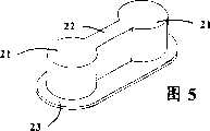
图5是具有底部凸缘的连接件的透视图;Figure 5 is a perspective view of a connector with a bottom flange;
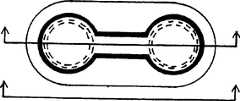
图6是图5的连接件的平面图;Figure 6 is a plan view of the connector of Figure 5;
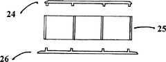
图7a和7b是分别沿图6的线AA和BB的视图,图7b显示了连接件的各部件的分解图;Figures 7a and 7b are views along lines AA and BB of Figure 6, respectively, and Figure 7b shows an exploded view of the components of the connector;
图8显示了连接件的一个可选实施例的示意性视图;Figure 8 shows a schematic view of an alternative embodiment of a connector;
图9显示了使用中的连接件的示意性视图;Figure 9 shows a schematic view of the connector in use;
图10显示了组件的局部剖开的侧视图;Figure 10 shows a partially cut-away side view of the assembly;
图11a、11b、11c、11d显示了跑道件的零件的剖视图;Figures 11a, 11b, 11c, 11d show cross-sectional views of parts of the racetrack;
图12a和12b显示了适用于结合其它部件如桥梁件等的定制跑道件;Figures 12a and 12b show custom runway pieces suitable for use in combination with other components such as bridge pieces etc.;
图13和14显示了其他跑道件及其相互连接的可选形状;Figures 13 and 14 show alternative shapes for other raceway elements and their interconnections;
图15和图16显示了可选的跑道件的结构;Figures 15 and 16 show the construction of an optional track piece;
图17a至17h显示了可选连接件结构的视图;Figures 17a to 17h show views of alternative connector structures;
图18a至18g显示了可采用的各种路径结构;Figures 18a to 18g show various path structures that can be used;
图19a至19d显示了本发明的连接件的特别优选的实施例;和Figures 19a to 19d show a particularly preferred embodiment of the connector of the present invention; and
图20显示了本发明的连接件的又一实施例。Figure 20 shows yet another embodiment of the connector of the present invention.
具体实施方式Detailed ways
参见图1,正方形的拼块或面板1具有大致同平面的上表面2和四条边缘3a至3d。上表面2具有多条跑道或通道6(见图2),等距地间隔开的成对跑道6限定了从一条边穿过拼块1至平行边的、十条或更多条的路径4a至5e和5a至4e。各路径具有入口点E1和出口点E2。尽管入口点E1和出口点E2显示为通过直的跑道6相连,然而可以理解,图1所示拼块1只不过显示了一般构造的路径和入口点以及出口点,跑道可遵循入口点与出口点之间的任何路径,并受到玩具车的转弯道的约束。Referring to Figure 1, a square tile or
然而,最好采用入口点E1和出口点E2相对于拼块边的标准位置,以便促进跑道在相邻拼块之间的对准。通过等距的间隔,跑道可用于限定次组的路径7。However, it is preferred to adopt standard locations of entry pointE1 and exit pointE2 relative to the edge of the tiles in order to facilitate alignment of the runways between adjacent tiles. With equidistant spacing, runways can be used to define paths 7 of secondary groups.
理论上,可在单个拼块上形成任意数量的跑道,但在实践中受到超过某一点的跑道宽度的实际限制,跑道将与另一条跑道合并并失去连贯性。然而,组件提供了比已知系统高许多倍的跑道密度。例如多种不同构造的跑道显示于图18中。In theory, any number of runways can be formed on a single tile, but in practice there is a practical limit to the width of the runway beyond a certain point where the runway will merge with another and lose continuity. However, the components provide a runway density many times higher than known systems. For example, a number of different configurations of runways are shown in FIG. 18 .
图18a显示了具有最常使用路径的一般拼块,然而可以理解,单个拼块不包括所有可能的路径;Figure 18a shows a generic tile with the most frequently used paths, however it will be appreciated that a single tile does not include all possible paths;
图18b显示了带有在拼块表面上形成的粗体标出的跑道的拼块,形成了“长的”换向设置;Figure 18b shows a tile with boldly marked runways formed on the tile surface, forming a "long" commutation setup;
图18c和18d分别显示了“短的”和“返回的”换向设置;Figures 18c and 18d show the "short" and "returned" commutation settings respectively;
图18e和18f分别显示了“返回的”和“通用的”换向设置;Figures 18e and 18f show the "returned" and "generic" commutation settings, respectively;
图18g显示了“五分路”的设置。Figure 18g shows the "five-way" setup.
拼块的下部主表面3也可设跑道。下表面3上的路径具有与上表面2的路径不同的构造,拼块可翻转用。图3和4显示了具有不同路径的拼块的组件的一些示例,拼块设置成可形成玩具车的部分回路。左边的拼块显示了上表面2,右边的拼块显示了各拼块的下表面3。The lower main surface 3 of the piece can also be provided with a runway. The path on the lower surface 3 has a different configuration from the path on the
各拼块边3a至3d具有位于各角部的成形凹部8。各凹部具有大致圆形横截面的球状内部10,以及内部10与拼块3连通的较窄颈部11。Each block side 3a to 3d has a shaped recess 8 at each corner. Each recess has a spherical interior 10 of substantially circular cross-section, and a narrower neck 11 through which interior 10 communicates with block 3 .
凹部8的中心定位于最外路径4a、4e、5a和5e的跑道6之间,并且与拼块角部的距离是等距的。这种设置允许任何拼块的任何边连接任何其他拼块的任何边,并且拼块的最外边对齐。凹部位置的其它合适的设置,例如单个中心定位的凹部也具有相同的效果。在下文中更详细地介绍将拼块保持在一起的连接件或肘节。The center of the recess 8 is located between the
从图4中可以看出,并非组件中的所有拼块都必须是方形的;图4所示下方的拼块是矩形的,并带有长度为两条长边一半的一对短边。其中一条短边设有另外的凹部8’,以允许拼块的相关路径与其它类型跑道系统的跑道件相连。图13和14所示拼块是三角形和六角形的。一般最好拼块形状允许嵌入。As can be seen in Figure 4, not all pieces in an assembly are necessarily square; the lower piece shown in Figure 4 is rectangular with a pair of short sides half the length of the two long sides. One of the short sides is provided with a further recess 8' to allow the relative path of the tiles to be connected to track elements of other types of track systems. The tiles shown in Figures 13 and 14 are triangular and hexagonal. It is generally best that the tile shape allows embedding.
图12a和12b显示了另一种拼块构造,可与桥梁件或其它跑道特征相结合。Figures 12a and 12b show an alternative block construction that can be combined with bridge pieces or other runway features.
形成各路径的成对跑道6可被单个通道9(见图11c),一对突起,模拟轨道跑道,或例如模拟行车道的单个突起来代替。The pairs of
在各跑道之间的间隔可被上色和以绘画突出,以便形成布景或其它图案,进一步增强组件的吸引力。The spaces between the various tracks can be colored and highlighted with painting to create scenery or other patterns, further enhancing the attractiveness of the assembly.
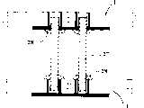
连接件或肘节20(见图5和6)具有相对的端部21,其通过中心杆或条22连接起来。端部21和条22分别具有与凹部8的内部10和颈部11的形状互补的形状。条22为颈部11或凹部的大约两倍长度,因此肘节20以紧密对接的方式将拼块连接起来。A link or toggle 20 (see FIGS. 5 and 6 ) has opposite ends 21 connected by a central rod or
尽管拼块的内部10和肘节20的端部21的横截面为圆形,然而可以理解,可以采用燕尾形和任何形状,只要形状是互补的并且凹部的内部的最大宽度大于颈部11的最大宽度。同样,颈部11和条22也可采用其它形状。Although the cross-section of the interior 10 of the piece and the
肘节20优选具有凸缘板23,其在肘节的底部提供了周边。肘节可以是单件结构,但优选采用三件式结构,具有上面板24和下面板26以及中心主体部分25(见图7a和7b)。肘节的三个部件成为可释放的卡扣接合,并且可以装配好的形式或成套形式提供给使用者。The toggle 20 preferably has a
肘节可设有均带凸缘的两个下面板26。其中一个面板26可在肘节连接在拼块上之后连接到肘节主体25上,因此在使用中,凸缘将拼块之间的邻接部分夹在中间并使拼块保持牢固接合。或者,肘节可由弹性材料形成,并受压与拼块凹部形成“压配合”。如果拼块用于建筑类玩具,其中拼块用作建筑物面板以形成房屋的时候,这种形式的肘节是特别有用的。“双凸缘”式肘节为拼块之间提供了更牢固的连接,即使在拼块处于垂直位置时也是如此。带有两个凸缘的肘节还可用于玩具车组件所用拼块之间需要更牢固连接的情况,例如形成半永久性的组件。The toggle may be provided with two lower panels 26, each flanged. One of the panels 26 may be attached to the
图8显示了一种可选的肘节20’。肘节20’的总体形状与肘节20相同,由三件式结构件组成。然而,肘节20’具有两个不同的端件,各端件具有连接在竖直的圆柱形管21’上的凸缘23’。管21’具有沿其长度延伸的开口或缝隙,用于容纳具有与肘节20的主体相似的总体形状的中心隔板22’。隔板22’的同样为空心圆柱形的两端分别容纳和保持在管21’中,隔板用于将端件21’、23’保持对齐。端件21’、23’可具有相同的结构,以便降低制造成本。Figure 8 shows an alternative toggle 20'. The toggle 20' has the same general shape as the toggle 20 and consists of a three-piece structure. However, the toggle 20' has two distinct end pieces, each end piece having a flange 23' attached to a vertical cylindrical tube 21'. Tube 21' has an opening or slot extending along its length for receiving a central bulkhead 22' having a similar general shape to the main body of toggle 20. Both ends, also hollow cylindrical, of the spacer 22' are housed and held respectively in the tube 21', the spacer serving to keep the end pieces 21', 23' in alignment. The end pieces 21', 23' may have the same structure in order to reduce manufacturing costs.
可通过在隔板的两端之间提供切口部分,使得隔板中心部分包括上部和下部支杆或支柱(见图2),从而提高隔板的柔性。The flexibility of the diaphragm can be increased by providing a cut-out portion between the ends of the diaphragm so that the central portion of the diaphragm comprises upper and lower struts or struts (see Figure 2).
可选择的肘节20’在两个拼块之间提供了铰接结合,使得拼块可运动至其主表面相互面对的位置,而无须取下肘节20’。结果,可选的肘节20’允许大组件紧凑地存放和容易地运输。The optional toggle 20' provides an articulating joint between the two pieces so that the pieces can be moved to a position where their major surfaces face each other without removing the toggle 20'. As a result, the optional toggle 20' allows compact storage and easy transport of large assemblies.
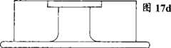
图17描述了另一可选肘节的构造。图17b显示了另一可选肘节20”的平面图。肘节是由弹性的柔性材料如橡胶形成的单件式结构。图17d显示了肘节20”的侧视图(另一侧视图相对应),图17a和17c显示了中心的横向和纵向剖面图。具有均匀宽度的单个周围凸缘23”包围了端部21”和中心部分”。如同邻近切去部分24的变窄腰部25,形成于两个端部之间的凸缘23”的切去部分24增加了肘节20”的柔性。Figure 17 depicts another alternative toggle construction. Figure 17b shows a plan view of another alternative toggle 20". The toggle is a one-piece structure formed from a resilient, flexible material such as rubber. Figure 17d shows a side view of the toggle 20" (another side view corresponds to ), Figures 17a and 17c show transverse and longitudinal cross-sections of the center. A single
中心部分22”的上部26是颠倒的C形截面。C形截面的臂40增强了肘节20”抵抗侧向运动和扭转运动的能力。臂40的外表面还可用于形成与装饰性镶块相接合的接合面。The upper portion 26 of the
图17e至17h的肘节20具有与肘节20”类似的结构,但设置了可取下的中心部分,并且肘节20的端部分开形成。The toggle 20'' of Figures 17e to 17h has a similar construction to the toggle 20" but with a removable central portion and the end portions of the toggle 20'' are formed separately.
图9更清楚地显示,肘节20”和20设置在端部与中心部分的上部或支柱26之间的界面区域,以便有助于界面折叠。特别是,端部的相对壁的宽度比外壁更窄,相对壁的宽度在界面区域进一步变窄。界面区域的形状,在图9所示的折叠构造中,使得支柱26的上侧与端部的内壁的邻接部分紧贴在一起,使得可实现更紧凑的折叠设置。Figure 9 shows more clearly that the toggles 20" and 20'' are arranged in the interface region between the end and the upper portion of the central portion or strut 26, so as to facilitate interfacial folding. In particular, the width of the opposing walls of the end is greater than The outer wall is narrower, and the width of the opposite wall is further narrowed in the interface area. The shape of the interface area, in the folded configuration shown in Figure 9, makes the upper side of the strut 26 close to the adjoining part of the inner wall of the end, so that Allows for more compact folded setups.
肘节的空心端部21可用于安装附件,如板上的信号杆等。肘节20的上面板24可取下,将附件端部插入。其它附件可包括棒27,用于将一层拼块支撑于另一层上。相对肘节20的上、下面板26,24可取下,将棒27插入。支座28将拼块1保持处于正确的垂直对准位置(图10)。The
参见图11,可以提供多个镶块或镶嵌体。镶嵌体30a至30f设置了突起,用于与跑道6或通道9相接合,或者其尺寸设置成可配合跑道或通道。镶嵌体可上色,预作标记,或者是空白的以便在上面书写。镶嵌体如30f比通道6要窄,可使使用者产生“轨道”的印象。另外,镶嵌体30f可上色,以便区分拼块的组件上的不同路径。Referring to Figure 11, multiple inserts or mosaics may be provided. The inlays 30a to 30f are provided with protrusions for engaging the
可以构思出许多种不同的预印的镶嵌体,以便增加组件的教育效果。例如拼块适当地设置成提供圆形路径时,相应形状的预印镶嵌体可设有不同的钟表面部件。因此使用者可在监督下组装这些部件。Many different pre-printed mosaics can be conceived to increase the educational effect of the assembly. For example where the tiles are suitably arranged to provide a circular path, a correspondingly shaped pre-printed mosaic may be provided with different clock face components. The user can thus assemble the parts under supervision.
接下来参见图19,图中显示了本发明的肘节的另一实施例,其结构可容易地折叠,以便使已安装好的跑道易于折叠,以实现紧凑存放。图19的肘节120由两个分开的对称部分121a,121b形成,各部分带有肘节120的端部122以及一部分中心杆123,中心杆在端部122之间延伸。肘节的各个半部121a,121b还包括如上所述的底部凸缘125。橡皮带124形式的弹性体部件连接到两个端部并在两者之间延伸,橡皮带具有圆形端部,各端部容纳在肘节120的各端部122形成的环形凹部接近,使得中心杆123的两个半部紧贴在一起,如图19a所示,同时允许肘节在第一方向上对半折叠以使两个部分121a,121b的底部凸缘125如图19c所示面对面地接合在一起,或者在第二方向上使端部122的上端如图19d所示面对面地接合在一起。因此,这种设置使邻接的跑道件可折叠在一起,以便折叠成特殊的跑道布置,用于紧凑存放。Referring next to Fig. 19, another embodiment of the toggle of the present invention is shown, which is configured to be easily foldable so that the installed track can be easily folded for compact storage. The
如同以上实施例,各端部122包括位于其上端的凹部,其中可容纳布景件等的安装销,但其中最好容纳有锁定板,其在两个端部122之间延伸以便防止这两者之间的相对运动,同时还可以形成阻止跑道件相对上升的上部凸缘。As with the previous embodiments, each
如图19b所示,各肘节部分121a,121b上的端部122的顶部具有铰接盖1265,其抬起以便能接近所形成的环形凹部,从而有助于将弹簧箍正确地定位在凹部中。As shown in Figure 19b, the top of the
图20显示了肘节的另一实施例,其与图19中的实施例基本相同,不同之处是,通过本技术领域中众知类型的双活铰链,肘节的两个部分连接在一起,这种铰链可使这两个部分围绕枢轴线侧面相互折叠,与图19的肘节的连接方式类似,可在第一方向上使底部凸缘对接,或在相反方向上使其端部的上表面接合。中心的轴向延伸孔形式的凹部也同样形成于各端部,以便与锁定板、布景等相接合。Figure 20 shows another embodiment of a toggle which is substantially the same as that of Figure 19 except that the two parts of the toggle are joined together by a double living hinge of a type well known in the art , such a hinge allows the two parts to be folded sideways about a pivot axis, in a manner similar to that of the toggle joint of Figure 19, with the bottom flanges abutting in a first direction, or their ends in the opposite direction. The upper surface is bonded. A recess in the form of a central axially extending hole is likewise formed at each end for engagement with a locking plate, scenery or the like.
在这种设置中,肘节的端部之间的间距可以略小于相邻跑道件的对准凹部之间的间距,从而使肘节的这两个部分之间的铰接连接处于张力状态,从而消除了铰链中因制造公差所导致的任何间隙。In such an arrangement, the spacing between the ends of the toggle may be slightly smaller than the spacing between the aligned recesses of adjacent track pieces, thereby placing the hinged connection between the two parts of the toggle in tension, thereby Any play in the hinge due to manufacturing tolerances is eliminated.
在所述实施例的情况下,端部和形成于跑道件的相关凹部的尺寸最好设置成具有紧公差配合,从而保证跑道件牢固地固定在一起。肘节的端部的尺寸还最好设置成不大于现有第三方跑道件中的凹部的尺寸,从而使其能用于现有的第三方的跑道件,尽管在肘节的端部与现有跑道形成的凹部之间可存在松配合。In the case of the described embodiment, the end portions and the associated recesses formed in the track elements are preferably dimensioned to have a close tolerance fit, thereby ensuring that the track elements are securely fastened together. The size of the end of the toggle is also preferably set to be no larger than the size of the recess in the existing third-party track piece, so that it can be used for the existing third-party track piece, although the end of the toggle is not the same as the current one. There may be a loose fit between the recesses formed by the raceway.
拼块的跑道6或通道9可通过在拼块中磨铣或切削出槽来形成。切削槽允许有更大灵活性的跑道布置,以及在需要时进行定制生产。或者,在材料允许的情况下,拼块可通过工艺如注射模塑,被预成形或模制形成槽。The
图15显示了新颖的拼块结构。凸起部分50被冲压出或与拼块1一体地形成,以便提供玩具车的下坡斜道。凸起部分可以是螺旋形,由凸起部分所形成的路径与拼块的围绕凸起部分的平面部分上的路径相邻接。Figure 15 shows the novel tile structure. The raised
本领域的技术人员可以理解,在不背离所附权利要求的范围的前提下,可以对本发明的上述示例性实施例进行修改。例如,各拼块的下部主表面3可设有重复利用的表面,如“干擦”板,使得当将该板翻转时,可为使用者提供画图或写字的大面积。或者,多个拼块的下主表面3可预印上情节串连图或游戏,例如蛇和梯游戏。It will be appreciated by those skilled in the art that modifications may be made to the above-described exemplary embodiments of the invention without departing from the scope of the appended claims. For example, the lower major surface 3 of each piece may be provided with a reusable surface, such as a "dry erase" board, so that when the board is turned over, a large area is provided for the user to draw or write on. Alternatively, the lower main surface 3 of the plurality of pieces may be pre-printed with a storyline or game, such as a snake and ladder game.
另外,跑道件可横向地分成多个单独部件,各部件沿着与横向分开大致成直角的轴线柔性地连接。这种设置可允许拼块在平面结构与横截面为大致S形的结构之间运动,因此可将不同水平层的拼块连接起来。Additionally, the track element may be divided laterally into a plurality of individual components, the components being flexibly connected along an axis generally at right angles to the lateral separation. This arrangement allows the movement of the tiles between a planar configuration and a substantially S-shaped cross-section, thus connecting tiles at different levels.
Claims (24)
Applications Claiming Priority (2)
| Application Number | Priority Date | Filing Date | Title |
|---|---|---|---|
| GB0221156AGB2401067B (en) | 2002-09-12 | 2002-09-12 | Assembly for guiding toy vehicle |
| GB0221156.3 | 2002-09-12 |
Publications (1)
| Publication Number | Publication Date |
|---|---|
| CN1694749Atrue CN1694749A (en) | 2005-11-09 |
Family
ID=9943925
Family Applications (1)
| Application Number | Title | Priority Date | Filing Date |
|---|---|---|---|
| CN03825044.6APendingCN1694749A (en) | 2002-09-12 | 2003-09-05 | A component that guides a toy car |
Country Status (7)
| Country | Link |
|---|---|
| US (1) | US20050287905A1 (en) |
| EP (1) | EP1551521A1 (en) |
| CN (1) | CN1694749A (en) |
| AU (1) | AU2003263321A1 (en) |
| CA (1) | CA2498513A1 (en) |
| GB (1) | GB2401067B (en) |
| WO (1) | WO2004024275A1 (en) |
Cited By (1)
| Publication number | Priority date | Publication date | Assignee | Title |
|---|---|---|---|---|
| CN109364498A (en)* | 2017-06-21 | 2019-02-22 | 美泰有限公司 | Toy car track system and its connector |
Families Citing this family (16)
| Publication number | Priority date | Publication date | Assignee | Title |
|---|---|---|---|---|
| US6935574B2 (en)* | 2003-11-12 | 2005-08-30 | Turbo Tec Company Limited | Toy-vehicle track section |
| FR2890571A1 (en)* | 2005-09-12 | 2007-03-16 | Patrice Marcel Edouard Bonneau | UNIQUE GEOMETRIC MODULE AS THE BASE, IN ISOLATED OR ASSEMBLED MODE, IN THE DRAWING OF RAILS CONSISTING OF A TRACK OR A CIRCUIT FOR VEHICLES AND CLOSING ONLY IN THE CASE OF A CLOSED CIRCUIT |
| EP1864704A1 (en)* | 2006-06-06 | 2007-12-12 | Marco Perego | Modular play structure |
| WO2010039133A1 (en)* | 2008-10-01 | 2010-04-08 | Learning Curve Brands, Inc. | Track system for toy vehicles |
| GB2470438B (en)* | 2009-08-28 | 2011-04-27 | Karen Margaret Chapman | Eating aid |
| US9220990B2 (en)* | 2010-09-22 | 2015-12-29 | Disney Enterprises, Inc. | Multi-lane track system |
| US8950719B2 (en)* | 2012-01-24 | 2015-02-10 | International Business Machines Corporation | Integrated rack installation apparatus and method |
| EP2956220A4 (en)* | 2013-02-15 | 2016-10-05 | Tamás Kertész | Sports equipment formed with joining element |
| FR3047050B1 (en)* | 2016-01-21 | 2018-07-13 | Ar | MODULAR TYPE SYSTEM |
| USD828880S1 (en) | 2017-06-21 | 2018-09-18 | Mattel, Inc. | Connector for flexible track sets |
| USD828879S1 (en) | 2017-06-21 | 2018-09-18 | Mattel, Inc. | Connector for flexible track sets |
| WO2019126779A1 (en)* | 2017-12-22 | 2019-06-27 | Thoughtfull Toys, Inc. | Toy vehicle track system |
| GB2590444A (en)* | 2019-12-18 | 2021-06-30 | Hornby Hobbies Ltd | Racing system |
| DE102023126755B3 (en) | 2023-09-29 | 2024-11-21 | Yamba (pty) GmbH | connecting element for toy train tracks |
| SE546801C2 (en)* | 2023-12-06 | 2025-02-18 | Flexlink Ab | Track tile module, modular track system, and method for manufacturing a track tile module |
| SE547191C2 (en)* | 2023-12-06 | 2025-05-20 | Flexlink Ab | Track tile module, modular track system, and method for manufacturing a track tile module |
Family Cites Families (9)
| Publication number | Priority date | Publication date | Assignee | Title |
|---|---|---|---|---|
| FR1278198A (en)* | 1960-10-29 | 1961-12-08 | Game representing a course for toy vehicles | |
| US3830426A (en)* | 1972-07-24 | 1974-08-20 | Aurora Prod Corp | Model vehicle race track |
| FR2223957A5 (en)* | 1973-04-02 | 1974-10-25 | Parant Daniel | Game with simulated roadway - with plug-in flush fitting edge pieces to interconnect sections |
| FR2602080B1 (en)* | 1986-07-25 | 1988-10-21 | Cauchois Jacky | RELATED MODULES CONSTITUTING A CIRCUIT. |
| US5139198A (en)* | 1986-12-11 | 1992-08-18 | Niehoff Joerg | Model train track for electrical model trains |
| DE3642350A1 (en)* | 1986-12-11 | 1988-06-23 | Joerg Niehoff | MODEL RAILWAY TRACK FOR ELECTRICAL MODEL RAILWAYS |
| DE29805208U1 (en)* | 1998-03-23 | 1998-06-04 | Epping, Astrid, 21521 Wohltorf | Driving course for toy cars |
| DE20013898U1 (en)* | 2000-08-11 | 2000-12-07 | STS Racing GmbH, 90449 Nürnberg | Car racing track and fastener and track part for this |
| DE10129275A1 (en)* | 2001-06-18 | 2003-01-09 | Carl Heynemann | Special element used in the construction of road and countryside surfaces in miniature model construction has a plate with a track-free section next to a track section |
- 2002
- 2002-09-12GBGB0221156Apatent/GB2401067B/ennot_activeExpired - Fee Related
- 2003
- 2003-09-05AUAU2003263321Apatent/AU2003263321A1/ennot_activeAbandoned
- 2003-09-05CNCN03825044.6Apatent/CN1694749A/enactivePending
- 2003-09-05CACA002498513Apatent/CA2498513A1/ennot_activeAbandoned
- 2003-09-05EPEP03795063Apatent/EP1551521A1/ennot_activeWithdrawn
- 2003-09-05WOPCT/GB2003/003877patent/WO2004024275A1/ennot_activeApplication Discontinuation
- 2003-09-05USUS10/527,282patent/US20050287905A1/ennot_activeAbandoned
Cited By (1)
| Publication number | Priority date | Publication date | Assignee | Title |
|---|---|---|---|---|
| CN109364498A (en)* | 2017-06-21 | 2019-02-22 | 美泰有限公司 | Toy car track system and its connector |
Also Published As
| Publication number | Publication date |
|---|---|
| CA2498513A1 (en) | 2004-03-25 |
| GB2401067A (en) | 2004-11-03 |
| AU2003263321A1 (en) | 2004-04-30 |
| US20050287905A1 (en) | 2005-12-29 |
| GB0221156D0 (en) | 2002-10-23 |
| GB2401067B (en) | 2006-08-09 |
| EP1551521A1 (en) | 2005-07-13 |
| WO2004024275A1 (en) | 2004-03-25 |
Similar Documents
| Publication | Publication Date | Title |
|---|---|---|
| CN1694749A (en) | A component that guides a toy car | |
| US11229854B2 (en) | Toy building systems including adjustable connector clips, building planks, and panels | |
| CA2156450C (en) | Modular track for toy cars | |
| US11478694B2 (en) | Modular marble toy kit | |
| CN108367204A (en) | Magnetism building piece | |
| US6340323B1 (en) | Waterslide toy block construction system | |
| DE3543969A1 (en) | TOYS FOR TODDLERS | |
| US6398121B1 (en) | Toy train tracks | |
| WO2015172716A1 (en) | Freely assemblable toy track | |
| US5931099A (en) | Model train set with storage means and variable track arrangement | |
| US8597069B2 (en) | Toy race track system | |
| CN109173288B (en) | Intelligent mortise and tenon toy splicing module system | |
| US10512852B2 (en) | Toy vehicle track set | |
| US20240042340A1 (en) | Toy train track connector and riser system | |
| US20070015594A1 (en) | Stunt ramp for wheeled toy device | |
| US20040082258A1 (en) | Adapter block apparatus for accomodating toy vehicles | |
| US20070037479A1 (en) | Slotless toy racetrack and radio-controlled toy racecar kit | |
| US7591705B2 (en) | Miniature expandable toy train system | |
| WO1997033669A1 (en) | Transformable geometric construction set and three-dimensional structures configurable therefrom | |
| US8852008B2 (en) | Ramp system for extreme sports | |
| US20200391129A1 (en) | Toy Vehicle Raceways with Clipping Mechanism and Supporting Block Builder | |
| JP3132065U (en) | Mat toy | |
| US20060166591A1 (en) | Connecting toy | |
| CN2843567Y (en) | Connected toy table and stool assembly | |
| CN2696797Y (en) | Novel wooden train track |
Legal Events
| Date | Code | Title | Description |
|---|---|---|---|
| C06 | Publication | ||
| PB01 | Publication | ||
| C10 | Entry into substantive examination | ||
| SE01 | Entry into force of request for substantive examination | ||
| C02 | Deemed withdrawal of patent application after publication (patent law 2001) | ||
| WD01 | Invention patent application deemed withdrawn after publication |