CN1682667A - Replaceable Cartridge Assembly for Surgical Stapling and Cutting Instruments - Google Patents
Replaceable Cartridge Assembly for Surgical Stapling and Cutting InstrumentsDownload PDFInfo
- Publication number
- CN1682667A CN1682667ACNA2004100997420ACN200410099742ACN1682667ACN 1682667 ACN1682667 ACN 1682667ACN A2004100997420 ACNA2004100997420 ACN A2004100997420ACN 200410099742 ACN200410099742 ACN 200410099742ACN 1682667 ACN1682667 ACN 1682667A
- Authority
- CN
- China
- Prior art keywords
- base
- barrel assembly
- nail
- barrel
- firing
- Prior art date
- Legal status (The legal status is an assumption and is not a legal conclusion. Google has not performed a legal analysis and makes no representation as to the accuracy of the status listed.)
- Pending
Links
Images


Classifications
- A—HUMAN NECESSITIES
- A61—MEDICAL OR VETERINARY SCIENCE; HYGIENE
- A61B—DIAGNOSIS; SURGERY; IDENTIFICATION
- A61B17/00—Surgical instruments, devices or methods
- A61B17/11—Surgical instruments, devices or methods for performing anastomosis; Buttons for anastomosis
- A61B17/115—Staplers for performing anastomosis, e.g. in a single operation
- A—HUMAN NECESSITIES
- A61—MEDICAL OR VETERINARY SCIENCE; HYGIENE
- A61B—DIAGNOSIS; SURGERY; IDENTIFICATION
- A61B17/00—Surgical instruments, devices or methods
- A61B17/068—Surgical staplers, e.g. containing multiple staples or clamps
- A61B17/072—Surgical staplers, e.g. containing multiple staples or clamps for applying a row of staples in a single action, e.g. the staples being applied simultaneously
- A—HUMAN NECESSITIES
- A61—MEDICAL OR VETERINARY SCIENCE; HYGIENE
- A61B—DIAGNOSIS; SURGERY; IDENTIFICATION
- A61B17/00—Surgical instruments, devices or methods
- A61B2017/0023—Surgical instruments, devices or methods disposable
- A—HUMAN NECESSITIES
- A61—MEDICAL OR VETERINARY SCIENCE; HYGIENE
- A61B—DIAGNOSIS; SURGERY; IDENTIFICATION
- A61B17/00—Surgical instruments, devices or methods
- A61B17/068—Surgical staplers, e.g. containing multiple staples or clamps
- A61B17/072—Surgical staplers, e.g. containing multiple staples or clamps for applying a row of staples in a single action, e.g. the staples being applied simultaneously
- A61B2017/07214—Stapler heads
- A61B2017/07221—Stapler heads curved
- A—HUMAN NECESSITIES
- A61—MEDICAL OR VETERINARY SCIENCE; HYGIENE
- A61B—DIAGNOSIS; SURGERY; IDENTIFICATION
- A61B17/00—Surgical instruments, devices or methods
- A61B17/068—Surgical staplers, e.g. containing multiple staples or clamps
- A61B17/072—Surgical staplers, e.g. containing multiple staples or clamps for applying a row of staples in a single action, e.g. the staples being applied simultaneously
- A61B2017/07214—Stapler heads
- A61B2017/07285—Stapler heads characterised by its cutter
- A—HUMAN NECESSITIES
- A61—MEDICAL OR VETERINARY SCIENCE; HYGIENE
- A61B—DIAGNOSIS; SURGERY; IDENTIFICATION
- A61B90/00—Instruments, implements or accessories specially adapted for surgery or diagnosis and not covered by any of the groups A61B1/00 - A61B50/00, e.g. for luxation treatment or for protecting wound edges
- A61B90/03—Automatic limiting or abutting means, e.g. for safety
- A61B2090/038—Automatic limiting or abutting means, e.g. for safety during shipment
- A—HUMAN NECESSITIES
- A61—MEDICAL OR VETERINARY SCIENCE; HYGIENE
- A61B—DIAGNOSIS; SURGERY; IDENTIFICATION
- A61B90/00—Instruments, implements or accessories specially adapted for surgery or diagnosis and not covered by any of the groups A61B1/00 - A61B50/00, e.g. for luxation treatment or for protecting wound edges
- A61B90/08—Accessories or related features not otherwise provided for
- A61B2090/0814—Preventing re-use
Landscapes
- Health & Medical Sciences (AREA)
- Life Sciences & Earth Sciences (AREA)
- Surgery (AREA)
- Heart & Thoracic Surgery (AREA)
- Engineering & Computer Science (AREA)
- Biomedical Technology (AREA)
- Nuclear Medicine, Radiotherapy & Molecular Imaging (AREA)
- Medical Informatics (AREA)
- Molecular Biology (AREA)
- Animal Behavior & Ethology (AREA)
- General Health & Medical Sciences (AREA)
- Public Health (AREA)
- Veterinary Medicine (AREA)
- Surgical Instruments (AREA)
Abstract
Description
Translated fromChinese技术领域technical field
本发明涉及钉紧切除手术中进行病理诊断和治疗所用的一种外科钉紧、切断装置。更特别地,本发明涉及一种与外科钉紧和切割器械一起使用的可更换钉筒组件。该可更换钉筒组件包括一用于盛装钉子和刀具的钉筒外壳体和一具有垫圈的基座。The invention relates to a surgical nailing and cutting device used for pathological diagnosis and treatment in nailing resection. More particularly, the present invention relates to a replaceable barrel assembly for use with surgical stapler and cutting instruments. The replaceable nail barrel assembly includes a nail barrel housing for containing nails and knives and a base with a washer.
背景技术Background technique
在外科领域,缝合生理组织及切割生理组织的需求相当普遍。生理组织的缝合可以通过各种缝合装置,例如外科钉紧机来完成。生理组织的切割可以通过各种切割装置,例如解剖刀和外科剪刀来完成。外科手术过程中,在若干步骤中进行的生理组织的钉紧和切割增加了该过程的时间。为了减少这些程序步骤和用于各种外科手术过程的最终时间,已经开发了同时钉紧并切割所需生理组织的器械。正如本领域技术人员期待的,希望提供一种能够在一个过程中进行多个钉紧和切割操作的钉紧和切割器械。In the field of surgery, the need to suture and cut physiological tissues is quite common. The suturing of physiological tissues can be accomplished by various suturing devices, such as surgical staplers. Cutting of physiological tissue can be accomplished by various cutting devices, such as scalpels and surgical scissors. During a surgical procedure, stapling and cutting of physiological tissue occurs in several steps, adding to the time of the procedure. In order to reduce these procedural steps and the resulting time for various surgical procedures, instruments have been developed that simultaneously staple and cut the desired physiologic tissue. As would be expected by those skilled in the art, it would be desirable to provide a stapling and cutting instrument that is capable of performing multiple stapling and cutting operations in one session.
一些现有的外科器械提供了在装置致动或击发过程中在同一方向上操作的钉紧和切割机构。例如,钉紧的形成和生理组织的切割沿着生理组织的同一平面发生。这些器械通常使用一基座,该基座保持钉袋(或钉紧形成表面)和垫圈、壳体组件,其中壳体组件保持钉子和一刀具。在该现有器械中,基座通常是器械的的一个永久元件(单击发装置),而壳体组件可以是一个永久元件也可以是一个可重新装的组件(多激发装置)。生理组织在基座和壳体组件之间被捕获。该器械的致动使夹钳从壳体组件朝基座移动。钉子刺穿被捕获的生理组织,然后钉袋与基座接触,这将钉子形成为固定生理组织的预定形状。与钉子的形成同时的是,该器械的致动总是将刀具从壳体组件朝基座移动。刀具将生理组织推向基座,并且使刀具和垫圈接触基座,这便于生理组织的切割。垫圈以与在一切割板上进行切割类似的方式起作用。Some existing surgical instruments provide staple and cut mechanisms that operate in the same direction during device actuation or firing. For example, staple formation and tissue cutting occur along the same plane of the tissue. These instruments typically use a base that holds the staple pocket (or staple forming surface) and washer, a housing assembly that holds the nails and a knife. In such existing instruments, the base is usually a permanent element of the instrument (single firing device), while the housing assembly can be either a permanent element or a reloadable assembly (multiple firing device). Physiological tissue is captured between the base and housing assembly. Actuation of the instrument moves the jaws from the housing assembly toward the base. The nail penetrates the captured physiological tissue, and then the staple pocket contacts the base, which forms the nail into a predetermined shape for securing the physiological tissue. Concurrent with the formation of the nail, actuation of the instrument always moves the knife from the housing assembly towards the base. The knife pushes the tissue toward the base, and the knife and washer contact the base, which facilitates cutting of the tissue. Washers function in a similar manner to cutting on a cutting board.
垫圈通常由弹性材料制成并且是基座的一个永久元件。而刀具既可以是一个在壳体组件内致动的永久元件,也可以是一个位于壳体组件内的可重装元件。对于单击发器械,再击发后垫圈和刀具和整个器械一起被丢弃。由于后续的击发操作需要一个新的器械,因此单击发器械具有较高的附加费用。对于多击发器械,壳体组件被丢弃,一个新的壳体组件被重装,而基座和垫圈则用于后续的击发操作。Gaskets are usually made of resilient material and are a permanent element of the base. The cutter can be either a permanent element actuated within the housing assembly or a reloadable element located within the housing assembly. For single-firing instruments, the gasket and knife are discarded with the entire instrument after refiring. Single-firing instruments have a high additional cost, since a new instrument is required for the subsequent firing operation. For multi-fire instruments, the housing assembly is discarded, a new housing assembly is reassembled, and the base and gasket are used for subsequent firing operations.
由于垫圈通常由塑料材料制成,而刀具由金属材料制成,同一垫圈的多次击发会导致垫圈的降解。这可能会妨碍切割性能,因而是不希望的。Since washers are usually made of plastic materials and knives are made of metal materials, multiple firings of the same washers can cause the washers to degrade. This may hamper cutting performance and is therefore undesirable.
因此,希望提供一种适于在一个过程中高效地并有效地允许利用相应钉子进行多次切割的外科钉紧和切割器械。本发明提供了一种外科钉紧和切割器械,其包括一个可更换的钉筒组件,该钉筒组件具有一个钉子筒外壳体和一个固定有垫圈的基座。Accordingly, it would be desirable to provide a surgical stapling and cutting instrument adapted to efficiently and effectively allow multiple cuts with corresponding nails in one procedure. The present invention provides a surgical staple and cutting instrument, which includes a replaceable nail barrel assembly, the nail barrel assembly has a nail barrel outer shell and a base on which a washer is fixed.
附图说明Description of drawings
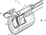
图1是根据本发明的线性外科钉紧器的透视图;Figure 1 is a perspective view of a linear surgical stapler according to the present invention;
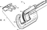
图2是拆去了钉筒组件的线性外科钉紧器的透视图;Figure 2 is a perspective view of the linear surgical stapler with the barrel assembly removed;
图3是将钉筒组件移动到一中间位置的线性外科钉紧器的透视图;Figure 3 is a perspective view of the linear surgical stapler moving the barrel assembly to an intermediate position;
图4是将钉筒组件移动到一关闭位置的线性外科钉紧器的透视图;Figure 4 is a perspective view of the linear surgical stapler moving the barrel assembly to a closed position;
图5是击发致动扳机处于致动位置的线性外科钉紧器的透视图;5 is a perspective view of the linear surgical stapler with the actuation trigger fired in the actuated position;
图6是钉筒组件的分解图;Figure 6 is an exploded view of the nail barrel assembly;
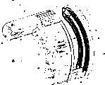
图7是固定有保持器的钉筒组件的前部透视图;Figure 7 is a front perspective view of the barrel assembly with the retainer fixed;
图8是拆去了保持器的钉筒组件的前部透视图;Figure 8 is a front perspective view of the nail barrel assembly with the retainer removed;
图9是钉筒组件的后部透视图,其详细地显示了钉子筒外壳体狭槽;Figure 9 is a rear perspective view of the barrel assembly showing the barrel outer housing slot in detail;
图10,11和12显示了保持器的组成;Figures 10, 11 and 12 show the composition of the retainer;
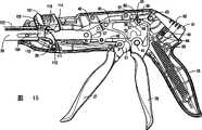
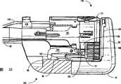
图13是线性外科钉紧器处于未致动状态的部分横截面图;Figure 13 is a partial cross-sectional view of a linear surgical stapler in an unactuated state;
图14是销致动机构的分解图;Figure 14 is an exploded view of the pin actuation mechanism;
图15是线性外科钉紧器的闭合扳机稍稍缩回时的部分横截面图;Figure 15 is a partial cross-sectional view of the linear surgical stapler with the closure trigger slightly retracted;
图16是线性外科钉紧器的闭合扳机接近完全缩回时的部分横截面图;16 is a partial cross-sectional view of the linear surgical stapler with the closure trigger nearly fully retracted;
图17是线性外科钉紧器的闭合扳机完全缩回时的部分横截面图;17 is a partial cross-sectional view of a linear surgical stapler with its closure trigger fully retracted;
图18是线性外科钉紧器的致动扳机和闭合扳机完全缩回时的部分横截面图;18 is a partial cross-sectional view of the linear surgical stapler with the actuation and closure triggers fully retracted;
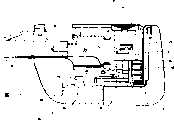
图19是外科医生压下释放按钮后的线性外科钉紧器的部分横截面图;Figure 19 is a partial cross-sectional view of the linear surgical stapler after the surgeon has depressed the release button;
图20是在释放了关闭和致动扳机后但还没有回到中间制动位置时的线性外科钉紧器的部分横截面图;Figure 20 is a partial cross-sectional view of the linear surgical stapler after the closing and actuating trigger has been released but not returned to the intermediate detent position;
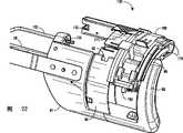
图21-29显示了钉筒组件的插入和保持器的拆除情况;Figures 21-29 illustrate the insertion of the barrel assembly and removal of the retainer;
图30-38显示了本线性外科钉紧器的致动过程包括的各个步骤;30-38 show the various steps involved in the actuation process of the present linear surgical stapler;
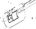
图39和40是钉子筒外外壳的详细前视图;Figures 39 and 40 are detailed front views of the nail barrel outer shell;
图41,42和43显示了钉筒组件的另一可替换的实施例。Figures 41, 42 and 43 show another alternative embodiment of the barrel assembly.
具体实施方式Detailed ways
这里将披露本发明的详细实施例。应当理解的是,所披露的实施例仅仅是本发明的示例,其可以以多种形式体现。因此,这里披露的细节不是作为限制内容来解释的,而仅仅是作为教导本领域技术人员如何制作和/或使用本发明的基础提出的。Detailed embodiments of the present invention will be disclosed herein. It is to be understood that the disclosed embodiments are merely exemplary of the invention, which may be embodied in various forms. Therefore, the details disclosed herein are not to be interpreted as limitations, but merely presented as basis for teaching one skilled in the art how to make and/or use the invention.
这里将披露本发明的详细实施例。应当理解的是,所披露的实施例仅仅是本发明的示例,其可以以多种形式体现。因此,这里披露的细节不是作为限制内容来解释的,而仅仅是作为教导本领域技术人员如何制作和/或使用本发明的基础提出的。Detailed embodiments of the present invention will be disclosed herein. It is to be understood that the disclosed embodiments are merely exemplary of the invention, which may be embodied in various forms. Therefore, the details disclosed herein are not to be interpreted as limitations, but merely presented as basis for teaching one skilled in the art how to make and/or use the invention.
参照各附图,本发明涉及一种适于以一个高控制方式钉紧被切割生理组织的外科器械20。该器械20通常包括一近端和一远端,一手柄21位于近端,一端部受动器80位于远端。该端部受动器80包括一U形支撑结构81,该U形支撑结构81的形状和尺寸设计得可以有选择地接收一钉筒组件,该钉筒组件容纳有多个外科夹紧件和一个刀具,用于有选择地使外科夹紧件和刀具126动作。该外科器械还包括一个与端部受动器80和钉筒组件120一起工作的击发机构。最后,钉筒120包括一个容纳有外科夹紧件和刀具的钉筒外壳121和基座122,该基座122的形状和尺寸设计成可以与外科夹紧件和刀具接合以便于切割和钉紧。钉子筒外壳121和基座122可以在分隔开的彼此相互靠近的第一位置和第二位置之间相对移动。Referring to the drawings, the present invention relates to a
参见附图1和附图2至5,它们显示了一种外科钉紧和切割器械,特别是一种设计用来钉紧和切割生理组织的线性外科钉紧器20。该线性外科钉紧器20具有一个位于第一近端处的手柄21和一位于相对的远端处的端部受动器80。根据本发明的最佳实施例,该端部受动器80呈曲线形。右侧和左侧手部结构板(通常成为“手柄板”)34,35分别将手柄21连接到器械的端部受动器80(右侧和左侧手部结构板在图1中未显示)。手柄21具有一与左手侧板连接的右手侧板22(左手侧板在图1中未显示)。手柄21还具有一用于抓握和操纵该线性外科钉紧器的主体部分23(参见图2-5)。Referring to accompanying drawing 1 and accompanying drawing 2 to 5, they have shown a kind of surgical stapler and cutting instrument, especially a kind of linear
端部受动器80是一个外科夹紧组件,其包括一个钉筒组件120(参见图6-9)和一个U形支撑结构81。闭合件28的末端30布置成容纳钉筒组件120。端部受动器80还包括一个安全停止机构180(最好参见图31)以用于阻止先前已经击发过的钉筒组件120再击发。该钉筒组件120包括一个与一基座122连接的钉筒外壳121。该钉筒组件120还包括一个保持销125、一个刀具126、一个可拆除的保持器160、一个生理组织接触表面127,该表面上具有位于刀具126两侧的一行或多行(也就是钉子行)以交错方式排列的多个钉子容纳狭槽128。钉子(未显示)抵靠着基座122的钉子形成表面129从钉子筒121外壳击发,该钉子形成表面129与钉子筒外壳121的生理组织接触表面127相对。The
正如通过下面的描述而可明确的那样,本发明的线性外科器械20设计为一个带有可更换钉筒组件120的多击发装置。但是,应当理解的是,本发明的许多根本理念完全可以等同地应用于单击发装置,这并不脱离本发明的精神。As will be apparent from the description below, the linear
端部受动器80的支撑结构81分别通过一个带肩部的铆钉82和栓件83和右侧及左侧手柄板34,35连接,其中栓件83从支撑结构81延伸进入手柄板34,35中的容纳孔。根据本发明的最佳实施例,支撑结构81由一个整体件构成。更特别地,该支撑结构通过诸如铝的挤压及随后的加工制成本发明所披露的支撑结构81。通过以这种方式构造支撑结构81,不再需要多个部件,从而显著地降低了加工和组装等相关费用。此外,支撑结构81的整体结构加强了本线性外科钉紧器20的整体稳定性。此外,支撑结构81的整体挤压结构将导致重量上的减轻、钴辐射有效地渗透该挤压铝制品而使杀菌更容易,挤压得到的平滑外表面也使得对生理组织的损伤更小。The
线性外科钉紧器20的手柄21包括一个医生用手掌抓住的手持部分24(见图2-5)。该手持部分24由一右手侧板手柄25(见图1)和一左手侧板手柄构成(左手侧板手柄在图1中未显示)。从手柄21的下侧枢轴延伸的是一闭合扳机26和一击发板机27。图1中显示的线性外科钉紧器20的关闭板机和击发扳机26、27处于非致动位置,并插有一钉筒组件120,而保持器160已经被拆除了。因此,钉筒外壳121与基座122分开,以将生理组织放置在钉筒外壳121和基座122之间。The
线性外科钉紧器20的手柄21包括一个生理组织保持销致动机构100。该生理组织保持销致动机构100包括一个位于手柄21顶面的鞍形滑动件101。手工移动鞍形滑道面101将导致推杆102向远端运动。该推杆102与钉筒120的保持销125连接。推杆102向远端运动或向近端缩回将导致保持销125的相应运动。保持销致动机构100也可释放地连接到手柄21内的闭合扳机26上,这样如果保持销还没有手工移动到其最近端位置,闭合扳机26的致动将导致保持销125自动向远端运动。The
参见图2-5,显示了钉筒组件120被装上,且闭合板机26和击发扳机27顺序压向手持部分24以致动线性外科钉紧器20的端部受动器80时的情况。该线性外科钉紧器20装在钉筒组件120内,如图2所示意,其中保持器160被拆除了。现在该线性钉紧器20准备接收生理组织,如图1中所示。Referring to FIGS. 2-5 , the
如图3所示,当部分推压闭合扳机26使其到达其第一停止位置时,钉筒外壳121从其完全打开位置到达位于打开和关闭位置间的一中间位置,这将在下面更详细地描述。同时,生理组织保持销致动机构100将保持销125从钉筒外壳121通过基座122上的一个开口向前移动。在该位置,放置在钉筒外壳121和基座122间的生理组织被适当定位,处于钉筒外壳121和基座122之间的生理组织的保持力是有保证的。因此,当闭合扳机26已经被致动到其中间位置时,钉筒外壳121和基座122也对应地位于它们的生理组织保持位置。As shown in FIG. 3, when the
如图4所示,当闭合扳机26完全被推压得与手持部分24的向前端邻接时,钉筒外壳121的生理组织接触表面127和基座122的钉紧形成表面129彼此相邻,该已经适当定位并保持的生理组织随后被完全夹紧。此外,击发板机27朝着手持部分24逆时针旋转,来使医生能够握住击发扳机27来击发钉紧。因此,击发扳机27目前处于被医生挤压来钉紧并切割生理组织的位置。如图5所示,当击发扳机27被完全挤压来击发钉紧时,击发扳机27位于靠近闭合扳机26处。As shown in FIG. 4 , when the
现在参照图6-9而将对钉筒组件120进行更详细的描述。该钉筒组件120设置有在线性外科钉紧器20内使用的切割和缝合机构,其中在装置致动期间,钉紧和切割功能在同一方向上作用。尽管钉筒组件120特别适于与线性外科钉紧装置一起使用,但是钉筒组件120的理念也可以用于其它外科装置,这并不脱离本发明的精神。特别地,钉筒组件120设置有在切割过程中与相应垫圈123一起使用的刀具126。钉筒组件120确保了线性外科钉紧器20的多次击发不会影响切割性能。这是通过基座122,特别是切割垫圈123和钉筒组件120协同完成的。通过将垫圈123和钉筒组件120组装在一起,每次更换钉筒组件120时均提供一个新的垫圈123,从而改进了切割性能。The
通过平行定位基座122和钉筒外壳121从而使它们的相对表面保持平行地彼此移动来进一步改进性能。这使得压力均匀分布在生理组织上,防止了下述方式的生理组织挤压:即可能集拢生理组织并迫使部分生理组织脱离基座122和钉筒外壳121间形成的预定空间。Performance is further improved by positioning the
更特别地,钉筒组件120包括一个钉筒外壳121,该外壳121容纳有多个定位在钉子容纳槽128中的钉子。紧接钉子后面设置的是一个将钉子从钉槽中推出的驱动件131。一个刀具保持器130放置在钉筒外121壳内的驱动件131附近。刀具保持器130包括一个狭槽172和凸缘173以与一个刀具牵引器的钩形件相互作用,该作用将在下面更详细地描述。刀具保持器130与一刀具126连接,该刀具126通过保持器131内的狭槽200和钉筒外壳内的狭槽199从刀具保持器130的末端延伸。More particularly, the
刀具保持器130具有一延伸通过钉筒外壳121上的狭槽137的定位支柱138。该刀具保持器130的定位支柱138定位于在刀具126和刀具保持器130的纵向运动过程中与钉筒狭槽137的定位突起139接触的位置处。类似地,驱动件131具有一个定位在分别与钉筒狭槽137的近端定位突起141和远端定位突起142接触的定位支柱140。
刀具126和狭槽199、200定位成在刀具126任一侧具有至少一排钉子。根据本发明的最佳实施例,两排钉槽128(和两排钉子)设置在钉筒外壳121的狭槽100的每侧。The
钉筒外壳121容纳有位于刀具狭槽199两端的通常为圆形的开口143、144。位于钉筒外壳121的基部的通常为圆形的开口143的形状和尺寸设计成用作引导销124通过钉筒外壳121的通道。位于钉筒外壳121的顶部的通常为圆形的开口144的形状和尺寸设计成用作保持销125通过钉筒外壳121的通道。钉槽128布置成钉子横向延伸通过这两个通常为圆形的孔143、144的形式。
根据本发明的最佳实施例,基座122包括一个塑料垫圈123和一个金属的钉紧形成表面129。该基座122设置成将钉紧形成表面129保持为一相配结构的形式。通过保持销125的周向狭槽135和联接件133上的凹槽134,保持销125与一个联接件133相连接(最好参见图14)。联接件133设置在钉筒外壳121的一支臂145内并通过端帽146保持在该支臂145内。According to the preferred embodiment of the present invention, the
引导销124和保持销125分别包括狭槽147a、147b(最好参见图8,9,36,39和40),刀具126的端部126a、126b分别设置在狭槽147a、147b内。引导销124的近端148与基座122的近端149相连。引导销124的远端150从钉筒外壳121延伸并延伸通过基座122的一狭槽151。通过将基座122的一凹槽152设置在垫圈123的舌边153之下而将切割垫圈123塞入基座122中。切割垫圈123的相对端154塞入基座支臂155之下并通过销钉156销接在基座支臂155上。在该位置,垫圈123的切割表面157向上延伸通过基座122的一狭槽151。切割垫圈123组装到基座122上将引导销124限制在由基座狭槽151和切割表面157形成的开口内,从而,可操作地将基座122连接到钉筒外壳121上。如图7所示,保持器160连接到钉筒组件120上来将钉筒组件120的部件保持在一预定方向上直到插入端部受动器80。
如上所述,根据本发明的最佳实施例,钉筒组件120包括一具有钉紧形成表面129和一垫圈123的基座122或基板。基座122由线性外科钉紧器20的支撑结构81的远端支撑。也就是说,钉筒组件120的基座122具有向后的表面,该向后的表面由支撑结构81的远端支撑,而该支撑结构81的远端是作为线性外科钉紧器20的支撑结构81的一个整体部分所形成的。更特别地,垫圈123与支撑结构81直接接触(见图6、7和22)。当向基座122施加力时,垫圈123抵靠在支撑结构81上。As mentioned above, in accordance with the preferred embodiment of the present invention, the
根据本发明最佳实施例,钉筒组件120包括一个钉筒外壳121,其中钉子和刀具126被容纳在其中以进行运动。基座122直接与钉筒外壳121相连并形成如上所述的钉筒组件120的整体部分。通过这种方式,基座122和钉筒外壳121形成一个完整的钉筒组件120,当需要多次击发外科夹紧装置时,该完整的钉筒组件120可以根据需要被更换。According to the preferred embodiment of the present invention, the
连接元件(将在后面详细描述)从钉筒组件120延伸,并将钉筒组件120连接到线性外科钉紧器20的支撑结构81的端部受动器80。通过这种方式,钉筒组件120位于线性外科钉紧器20内,而基座122直接位于线性外科钉紧器20的支撑结构81的基座支撑件82的前面。A connecting element (described in detail below) extends from the
通过可以促进钉筒组件相对于基座122的运动的钉筒外壳121和基座支臂155之间的滑动接合,来便于钉筒外壳121沿着线性外科钉紧器20的长轴的朝着基座122的向远端运动。保持器160设置于基座122和钉筒外壳121之间。保持器160阻止了钉筒外壳结构朝着基座122的不希望的运动。当准备使用该装置时,可以选择地拆除保持器160。Orientation of the
参见图41,图中显示了整体外壳结构/基座钉筒组件120′的另一可选择实施例。如前一实施例,该钉筒组件120′设置有一与线性外壳钉紧器20一起使用的切割和固定机构,其中在装置致动过程中钉紧和固定功能在同一方向上作用。该钉筒组件120′包括一个具有钉紧形成表面129′和一垫圈123′的基座122′。Referring to Fig. 41, another alternative embodiment of the overall housing structure/base barrel assembly 120' is shown. As in the previous embodiment, the barrel assembly 120' is provided with a cutting and securing mechanism for use with the
如前一实施例,基座122′由线性外科钉紧器的支撑结构的末端支撑。也就是说,该钉筒组件120′的基座122′具有一由支撑结构支撑的向后表面,该向后表面形成为线性外科支撑结构的一个整体部分。As in the previous embodiment, the base 122' is supported by the end of the support structure of the linear surgical stapler. That is, the base 122' of the cartridge assembly 120' has a rearward facing surface supported by the support structure, the rearward facing surface being formed as an integral part of the linear surgical support structure.
基座122′直接与钉筒外壳121′连接并形成为钉筒组件120′的一个整体部分。基座支臂155′将基座122′连接到钉筒组件120′的钉筒外壳121′。通过这种方式,基座122′和钉筒外壳121′形成为一个完成的钉筒组件120′,该钉筒组件120′位于多次击发线性外壳钉紧器内并且当需要时可以被更换。The base 122' is directly connected to the cartridge housing 121' and is formed as an integral part of the cartridge assembly 120'. Base arms 155' connect base 122' to cartridge housing 121' of cartridge assembly 120'. In this manner, base 122' and cartridge housing 121' form a completed cartridge assembly 120' that resides within the multi-fire linear housing stapler and can be replaced as needed.
连接销119′在钉筒组件120′的两端间延伸,并将钉筒组件120′连接到线性外科钉紧器的支撑结构。通过这种方式,钉筒组件120′位于线性外科钉紧器122′内,基座122′直接位于线性外科钉紧器122′的支撑结构的基座支撑件的前面。Connecting pin 119' extends between the ends of barrel assembly 120' and connects barrel assembly 120' to the support structure of the linear surgical stapler. In this manner, the barrel assembly 120' is positioned within the linear surgical stapler 122' with the base 122' directly in front of the base support of the support structure of the linear surgical stapler 122'.
通过设置一轨道118′来方便钉筒外壳121′沿着线性外科钉紧器20的长轴的朝着基座122′的向远端运动,当钉筒外壳121′朝着基座122′运动时,钉筒外壳121′骑越在轨道118′上。A track 118' is provided to facilitate the distal movement of the nail barrel shell 121' along the long axis of the linear
现在参照附图42和43描述另一实施例。该实施例包括一仅具有一垫圈123″的基座122″(基座的其余部分形成为端部受动器80″的支撑结构81″的一部分)。如上所述,垫圈123″在形成与支撑结构81″上的狭槽136″内滑动,来将钉筒组件120″固定到端部受动器80″。Another embodiment will now be described with reference to FIGS. 42 and 43 . This embodiment includes a base 122" having only one
基座122″直接与钉筒外壳121″连接并形成为钉筒组件120″的一个整体部分。一个基座支臂155″将基座122″连接到钉筒组件120″的钉筒外壳121″。连接销119″在钉筒组件120″的两端间延伸,并将钉筒组件120″连接到线性外科钉紧器的支撑结构81″。通过设置一轨道118″来方便钉筒外壳121″沿着线性外科钉紧器的长轴的朝着基座122″的末端运动,当钉筒外壳121″朝着基座122″运动时,钉筒外壳121″骑越在轨道118″上。The base 122" is directly connected to the
尽管已经应用了上述实施例,但是由基座和钉筒外壳构成的可更换部件可以作为一个完整的可更换头或可更换钉筒组件装配在一起。每个可更换头带有一个支撑桥部,该支撑桥部将钉筒外壳固定到垫圈上,使得垫圈与切割元件一体地形成。每个可更换头包括一个在运送过程中支撑该部件并防止钉子被放出的保持器。Although the above-mentioned embodiments have been applied, the replaceable parts consisting of the base and the cartridge housing can be assembled together as a complete replaceable head or replaceable cartridge assembly. Each replaceable head has a support bridge that secures the cartridge housing to the washer such that the washer is integrally formed with the cutting element. Each replaceable head includes a retainer that supports the part during shipping and prevents the nails from being played out.
最后,该钉筒组件具有一带有钉子形成表面的基座和一垫圈,其优于现有装置之处在于提供了一个允许多次击发但又不妨碍切割性能的切割机构。这是通过设置一用于每次击发的具有新垫圈和基座袋的新基座来实现的。此外,钉筒组件比单击发装置的费用要低,这是因为根据装置的应用,只需要更换带有基座的可更换头。Finally, the barrel assembly has a base with a nail forming surface and a washer that is superior to prior devices in providing a cutting mechanism that allows multiple shots without impeding cutting performance. This is accomplished by providing a new base with a new gasket and base pocket for each firing. In addition, the barrel assembly is less expensive than a single firing device because, depending on the application of the device, only the replaceable head with the base needs to be replaced.
现在参照附图6至12和附图25至29,更详细地描述保持器160。该保持器160具有一设置在钉筒外壳121的突起159周围的凹槽161。该保持器160包括一弹性的内部弹力支臂162,该弹性的内部弹力支臂162用于在保持器160内的往复运动。该保持器160包括围绕引导销124部分地延伸的容纳狭槽163。该弹力支臂162包括围绕引导销124部分地延伸的容纳狭槽164,但是该容纳狭槽164构造在面向容纳狭槽163的相对方向上。该保持器160定位于钉筒组件120上,使得容纳狭槽163、164围绕着引导销124并将保持器160限制在钉筒组件120上。弹力支臂162包括一从位于基座臂155之下的保持器160向下延伸的脱离突起165。这样,在钉筒组件120适当地位于端部受动器80之前,保持器160不会容易地从钉筒组件120上拆除。当钉筒组件120适当地位于端部受动器80时,脱离突起165脱离端部受动器80以释放保持器160。Referring now to FIGS. 6 to 12 and FIGS. 25 to 29 , the
现在参照图1和图2及图13,更详细地描述线性外科钉紧器20的各部件。该线性外科钉紧器20包括一个细长的闭合件28,该闭合件28具有一通常为U形的横截面并从手柄21延伸进入端部受动器80的外科紧固组件。根据本发明的最佳实施例,闭合件28是一个模制的塑料件,其形成为可以实现本发明的运动和功能的形状。通过用塑料制造该闭合件28,线性外科钉紧器20的制造费用和重量均降低了。此外,该线性外科钉紧器20更易于消毒,这是因为相对与金属来说,钴辐射更易于穿透塑料。根据一可变实施例,该闭合件可以通过挤压铝制品并将最终的特征加工在其位置上来得到。尽管挤压铝制品构成的闭合件的制造可能不象塑料制品的制造那么容易,但是其仍旧具有一些优势(如,减少部件数量、组装容易、重量轻、易于消毒等)。Referring now to FIGS. 1 and 2 and 13, the various components of the linear
闭合件28的端部通过支撑结构81的壁面84。末端设置成容纳和保持钉筒组件120的钉筒外壳121的形式。闭合件28的中部位于右侧和左侧手柄板34、35之间。通过一第一整体闭合连接销38,右手和左手闭合连接件36、37分别枢轴连接到闭合件28的右端和左端。在闭合连接件36、37的另一端,闭合连接件36、37枢轴连接到一第二整体闭合连接销39。该第二整体闭合连接销39将闭合连接件36、37连接到一带狭槽的闭合支臂连接件40上。该带槽的闭合支臂连接件40在一闭合扳机枢转销41处枢轴地安装到线性外科钉紧器20的手柄板34、35上。该闭合扳机26从带槽闭合臂式连接件40处向下延伸以围绕闭合扳机枢转销41朝着或远离手握持部24进行枢轴转动。容装在手柄21的手持部分24中的一根闭合弹簧42固定在带槽闭合臂式连接件40上,在医生朝着手持部分24按压闭合扳机26时,该闭合弹簧42提供所需的阻力以将闭合扳机26偏压向开启位置。The end of the
参考附图13、14,下面将对保持销致动机构100的部件进行描述。手柄21包括安装在手柄21顶部上的一个马鞍形滑动件101以进行线性运动。滑动件101通过手柄21中的槽105(参见图2)而与从一个推杆驱动件104向外延伸的一个栓杆103相连。推杆驱动件104受到槽105的限制而沿着线性外科钉紧器20的长轴进行纵向运动。推杆驱动件104通过推杆102上的周向槽107而与推杆102相连,所述推杆102卡持在推杆驱动件104的一个槽108中。推杆102通过位于其远端的一个周向槽109而与钉筒组件120的接合件133近端中的一个槽132相连(最好参见图22)。接合件133通过其远端的一个槽134而与保持销125上的一个周向槽135相连。Referring to Figures 13 and 14, the components of the retention pin actuation mechanism 100 will now be described. The
闭合件28包含有栓件29,栓件29在处于手柄21内侧的闭合件28的两侧上横向延伸。这些栓件29与轭件111的一个L形槽110滑动连接。轭件111通过其上的一个枢转销112枢轴地连接在手柄21上。轭件111包括有凸轮销113,该凸轮销113定位成推动推杆驱动件104上的凸轮表面114。The
参考图13和图37,下面将对击发传动组件的部件进行描述。击发传动组件具有一个细长的击发杆43,该击发杆43从手柄21延伸入端部受动器80的外科紧固组件中。击发杆43布置在闭合件28的U形截面中。击发杆43的远端延伸入钉筒外壳121中且与刀具保持件130和驱动件131的近端相邻布置。击发杆43的远端连接在具有刀具牵引钩45的一个刀具牵引件44上。Referring to Figures 13 and 37, the components of the firing drive assembly will now be described. The firing drive assembly has an elongated firing
击发杆43具有矩形的接收槽46,其中,击发杆43上具有接收槽46的这一部分容装在手柄21中(参见图13)。第一整体式闭合连结销38延伸通过所述接收槽46。击发杆43还具有一个近端部分47。击发杆43的近端部分47的下侧具有一个滑动表面48。近端部分47还具有一个从滑动表面48延伸出的止动侧向接合面49。击发扳机27通过与闭合扳机枢转销41相分离的一个击发枢转销50而可枢转地安装在手柄板34、35上,这样,每个枢转销就可围绕各自的轴线进行枢轴转。击发扳机27包括一个弓形的击发扳机连接件51,该击发扳机连接件5 1从击发扳机枢转销50处的击发扳机27处延伸至一个顶点52处,该顶点52处于击发杆43的近端部分47的滑动表面48上。在手柄21中,击发扳机27分别连接到第一和第二击发扳机弹簧臂53、54上。击发扳机弹簧臂53、54支撑处于击发扳机43右半边上的一根扭转弹簧(图中未显示)。最后,一根击发杆回复弹簧55固定在手柄21内的击发杆43的下侧部分处以将击发杆43偏压向其未致动位置。The firing
当朝着手持部分24推压闭合扳机26时,带槽的闭合臂式连接件40和闭合连接件36在击发杆43的接收槽46中朝着远端运动。这种朝着远端的运动使闭合件28相应地向远端运动。同样,击发杆43与闭合件28同时向远端运动,这是因为其上连接有闭合连接件36、37的第一整体式闭合连结销38延伸过击发杆43中的接收槽46。When the
下面将参考附图1并结合附图13-20而对限定中间闭合止动位置所用的机构及闭合扳机26从致动位置释放至其初始的未致动位置的情况进行描述。带槽的闭合臂式连接件40的顶侧具有一个夹紧滑动表面56,该夹紧滑动表面56显露出一个中间止动件57和一个闭合止动件58。一个释放罩59在该夹紧滑动表面56上滑动且可与中间止动件和闭合止动件57、58相接合。在释放罩59的远端具有一个横向延伸的罩片60(最好参见图1)。释放罩59定位在手柄21内且其整体式连接在处于手柄21外部的一个释放按钮61上。释放按钮61具有一个拇指放置部62,释放按钮61通过一个释放耳轴63枢轴地连接在手柄21上。释放按钮61被从手柄21向外偏压,这样,释放罩59就由一根释放弹簧64向下朝着夹紧滑动表面56偏压,释放弹簧64通过一个弹簧止动销65安装在手柄21上且通过一个按钮弹簧栓66安装到释放按钮61上。带槽的闭合臂式连接件40具有位于中间止动件57和闭合止动件58之间的一个弓形凹槽67。在该弓形凹槽67中布置有用于旋转运动的整体相连的一个左手肘板68和一个右手肘板(图中未显示该右手肘板)。每个肘板68具有可与罩片60相配合的一个肘板臂69。罩片60具有一个凹形的近端表面70以在肘板臂69和罩片60之间提供间隙。The mechanism used to define the intermediate closed detent position and the release of the
现在参考附图31(钉筒和支撑结构的剪切视图),下面将对击发装置锁止机构180的部件进行描述。锁止机构180包括一个锁止杆181,该锁止杆181通过一个销182而可枢转地安装到闭合件28的远端30上。锁止杆181由一根弹簧(图中未显示)朝着支撑结构81的基座向下弹性偏压。锁止杆181分别具有一个近端和一个远端184、185。近端184具有一个凸轮表面186和锁止槽187。端部受动器80的支撑结构81包括一个凸缘85,当锁止结构180接合时,凸缘85与锁止槽187相互作用。支撑结构81具有处于壁部84之间的一个基面86。在锁止杆181未被接合时,基面86被布置成与所述凸轮表面186相互作用。Referring now to FIG. 31 (cutaway view of the barrel and support structure), the components of the firing
下面将对钉筒组件120、闭合机构、保持销机构、击发传动组件、中间止动件57、闭合止动件58、释放机构及锁止机构180的加载操作进行描述。参考附图7-12和附图21-28而对将钉筒组件120加载到生理组织端部受动器80中的情况进行描述。该钉筒组件120的形状和尺寸设计成可以选择性地插入线性外科钉紧器20的生理组织端部受动器80中或从其上拆除。The loading operation of the
如图7所示,在将钉筒组件120插入线性外科钉紧器20的端部受动器80中之前,由于槽161围绕在保持件160的顶端处的凸起159布置而阻止分离,这样就不容易将保持件160从钉筒组件120上拆卸下来。此外,如图25所示,保持件的容装槽163、164在保持件160的底部处围绕导引销124布置而阻止分离。7, prior to inserting the
所连接的保持件160对钉筒组件120的结构及用于握持的一个延伸表面进行支撑,这些特征均使加载变得更为容易。保持件160可阻止钉子在不经意的处理过程中从钉筒外壳121中掉落下来且可阻止刀具126在不经意的处理过程中偶然暴露出来。The attached
在加载之前及在加载过程中可通过一系列的止动部件进一步阻止刀具126和钉子的移动。参考图9,通过钉筒外壳槽137上的止动凸起139则可阻止刀具保持件130上的止动栓138向远端和近端运动。通过止动栓140与钉筒外壳槽137上的止动凸起141的相互作用则可阻止由于不经意的处理而使驱动件131向远端运动,且在将钉筒组件120加载到线性外科钉紧器20的过程中阻止驱动件131向远端运动。Movement of the
如图21-24所示,将钉筒组件120加载到生理组织端部受动器80中,从而使钉筒外壳121滑入闭合件28的远端30中。在加载过程中,闭合件28上的壁部31a、31b滑入钉筒外壳121的槽170a、170b中。与此同时,凸片174(参见图8)滑入U形支撑结构81的槽88中。特别地,该凸片174是U形的且沿着支撑结构设置于槽88中,从而将钉筒组件120牢固地且精确地连接到端部部受动器80。如图21-24所示,当止动部171卡持到闭合件远端30的止动槽32上时则完成了钉筒组件120的加载。As shown in FIGS. 21-24 , the
在如图24所示的位置中,钉筒组件120被完全加载,接合件133的近端槽132与推杆102的远端周向槽109相结合,这样,钉筒组件120中的保持销125就与保持销推进机构100相连。在加载过程中,刀具保持件131的槽172与刀具牵引钩45相接合,从而使牵引钩45在完成钉筒组件120的加载时与刀具保持件130上的牵引凸缘173相接合。In the position shown in Figure 24, the
在完成钉筒组件120的加载时,布置在驱动件131上的一个栓件188与锁止杆181的远端185相接触(参见图31)。这种接触使锁止杆181围绕锁止杆销182而转动至一个位置,从而使凸轮表面186与U形的支撑结构81的基面86水平对准。When the loading of the
现在将保持件160从端部受动器80上拆除。特别地,钉筒组件120的加载的完成使脱离凸片165与支撑结构81相接触(参见图23),这样,如图24所示,当将钉筒组件120完全加载后,弹簧臂162向上移动。这种向上移动使容装槽164向上偏移而不再容装导引销124(参见图25和图26)。现在参考附图27-29,向拇指垫166施加一个拆卸作用力而使保持件160围绕凸起159向外枢转直至所述槽161可从凸起159上滑脱下来。将保持件160拆除则可使用该已被加载的线性外科钉紧器20。
在附图15中,闭合扳机26已从图1和图13所示的开启、未被致动位置处部分推压。在部分推压闭合扳机26时,该闭合扳机26就围绕闭合扳机枢转销41而在逆时针方向中朝着手持部分24转动。在闭合扳机26转动时,带槽的闭合臂式连接件40和闭合盘闭合连接件36、37向前移动,并随后向远端移动闭合件28和击发杆43。当带槽的闭合臂式连接件40向前移动时,释放罩59的罩片60在夹紧滑动表面56上滑动。罩片60与肘板68的肘板臂69的远端相配合,从而使肘板68在顺时针方向中枢转。当带槽的闭合臂式连接件40相应于闭合扳机26的枢转朝着手持部分24继续向前运动时,释放罩59的罩片60最终会容纳在中间止动部57中。一旦定位在中间止动部57中,闭合弹簧42就不能将闭合扳机26回复至其初始的未致动位置。闭合扳机26现在处于其中间部分的闭合位置中以将生理组织适当定位和保持在钉筒外壳121和基座122之间,就如在图15中所示的那样。此外,在闭合件28和击发杆43向远端移动时,弓形击发扳机连接件51的顶点52就在击发杆43的近端部分47的滑动表面48上滑动。In Figure 15, the
在从开启位置至中间位置的闭合行程中,保持销机构100被致动。闭合件28向前的运动使整体式栓件29向远端移动。栓件29与轭件111的L形槽110相接触。因此,栓件29向远端的运动使L形槽110进行凸轮转动,从而使所述轭件围绕销子112进行枢转。所述转动使轭件111上的支撑栓件113与推杆驱动件104上的凸轮表面114相接触。轭件111进一步的转动使支撑栓件113通过与表面114进行凸轮接触而向远端移动推杆驱动件104。推杆驱动件104与推杆102相接触而向远端移动所述推杆102。推杆102再顺次向远端移动接合件133和保持销125。至中间止动部57位置处所进行的闭合行程的完成使保持销125向远端移动通过钉筒外壳121的孔144、基座151的槽及垫圈170中的孔而进入支撑结构81中的孔89(图中未显示)。处于钉筒外壳121的接触表面127和基座122之间的生理组织现在被卡持在保持销125和导引销124之间。During the closing stroke from the open position to the intermediate position, the retaining pin mechanism 100 is actuated. Forward movement of the
在闭合之前通过人工将马鞍形滑动件101向远端移动也可实现同样的效果。所述滑动移动使推杆102、接合件133和保持销向前运动直至保持销125完全布置在支撑结构81内的基座122、垫圈123和孔89中。在将保持销125人工向前移动之后的闭合行程的致动仍会使轭件111进行上述的枢转,但不会使保持销致动机构100进行额外的运动。The same effect can also be achieved by manually moving the
如图31(开启位置)和附图32(中间位置)所示,当锁止杆181通过销182连接在闭合件28上时,从开启位置至中间止动部57位置处的闭合行程使锁止杆181向远端移动。锁止杆181向远端移动使凸轮表面186与支撑结构81的锁止凸缘85相接触,从而使锁止杆181顺时针转动且与支撑结构81的基面86滑动接触。在该位置中,锁止杆181的远端185已转动远离起动件131上的栓件188。As shown in Figure 31 (open position) and Figure 32 (intermediate position), when the locking
现在特别参考附图16,当将闭合扳机26从中间止动部57的位置朝着手持部分24推压时,肘板68的肘板臂69与罩片60脱离配合。这样,当肘板68继续在顺时针方向中转动时,释放罩片60跨越在肘板臂69上,闭合扳机26继续运动而落入闭合止动部58中。当释放罩59跨越在肘板臂69上时,它就使释放按钮61围绕枢轴63顺时针转动。当释放罩片60落入闭合止动部58中时,会产生可听得见的咔哒声以提醒医生已到达闭合位置。With particular reference now to FIG. 16 , when the
此外,在击发杆43继续向前移动时,弓形的致动击发扳机连接件51的顶点52与击发杆43的近端部分47的滑动接合表面49相接触。这样,击发扳机27就移动至一个位置中,在该位置处,击发扳机27继续向远端移动击发杆43以在完全夹持住生理组织之后击发钉子。当弓形击发扳机连接件51的顶点52与近端部分47的接合表面相接合时,击发扳机27相应于扳机27右手侧上的扭转弹簧(图中未显示扭转弹簧)的动作而在逆时针方向中朝着手持部分24枢轴转动。击发扳机27的枢转独立于闭合扳机26的枢转,但是其枢转受到阻挡直至击发杆43向远端移动而使击发扳机连接件51与击发杆43的最终接合表面相接合。Additionally, the apex 52 of the arcuate actuation firing
现在特别参考附图17,当闭合扳机26被完全推压而与手持部分24相邻时,处于释放罩59远端处的罩片60进入闭合止动部58中。在闭合止动部58的位置中,生理组织被完全夹紧在钉筒外壳121和基座122之间,闭合弹簧42不能使闭合扳机26回复至其初始位置。因此,闭合扳机26就被保持在图4所示的位置中。With particular reference now to FIG. 17 , when the
在闭合扳机26逆时针转动的同时,击发扳机27在击发杆在回复弹簧55的扭转作用下继续逆时针转动直至击发扳机27相对于线性外科钉紧器20的手柄21处于相对垂直的位置。在完全夹持的位置中,弓形击发扳机连接件51的顶点52与击发杆43的近端部分47的接合表面完全接合,这样,击发扳机27就处于一个位置中以进一步向远端移动击发杆43,从而将钉子射击到生理组织中。While the
如图33所示,在完全闭合位置中,钉筒外壳121的钉袋128与基座122的钉紧形成表面129相对准。保持销125使基座122的顶部与钉筒外壳121相对准,导引销124使钉筒外壳121的底部与基座122的底部相对准。As shown in FIG. 33 , in the fully closed position,
如图18和图34所示,可推压击发扳机27而使其朝着手持部分24转动直至使其与闭合扳机26相邻定位。在击发扳机27的转动过程中,击发杆43向远端移动而与刀具保持件130相接触。这样就使刀具保持件130向远端移动而与刀具126和驱动件131相接触。驱动件131向远端移动会将钉子(图中未显示)向远端推进到基座122的钉紧形成表面129中而将钉子形成为总体上为B形的形状。刀具126在与钉子形成相结合的导引销124和保持销125的槽147中向远端推进。这些槽147将刀具126导引到切割垫圈123的切割表面157上而切断被卡持在两部件之间的任何生理组织。As shown in FIGS. 18 and 34 , the firing
作用到击发扳机27的人工作用力的释放导致击发杆回复弹簧55将击发杆43和击发扳机27回复至图17所示的位置。这种运动使牵引钩45回撤到刀具保持件130和刀具126上的牵引凸缘173上。该向近端的运动将刀具126回撤到钉筒外壳121中,就如在附图35中所示的那样。刀具保持件130上的止动栓138回撤而与钉筒外壳121上的止动部139相接合从而将刀具保持件130和刀具126保持在该回撤位置中。通过驱动件131上的止动栓140与钉筒槽137的止动部142相接合则将驱动件131保持在其最远端位置(被击发位置)中。Release of the manual force applied to firing
由于使用者的失误可能会使刀具126与其他医用装置产生干涉,这样,击发杆回复弹簧55的作用力就不足以使击发杆43回撤而将刀具126牵引至钉筒外壳121中,使用者可通过顺时针拉动击发扳机27来人工回撤切割系统。这种人工顺时针移动使弓形击发扳机连接件51顺时针转动直至它冲击到击发杆43的近端47上的击发杆回撤片71。顺时针移动的击发扳机连接件51和击发杆回撤片71之间的接触使击发杆43向近端回撤且回复至图17所示的位置。这样再使牵引钩45回撤到刀具保持件130和刀具126的牵引凸缘173上。这样,这种安全特征可使使用者将切割机构回撤至一个安全的位置并将击发系统回复至可允许将线性外科钉紧器20打开的一个位置,在下文中将对该内容进行描述。Because the user's mistake may cause the
参考附图19,当医生按下释放按钮61时,释放罩59围绕释放耳轴63在顺时针方向中枢转而将罩片60从闭合止动部58的位置处驱出。在罩片60被驱出时,它跨越在肘板臂69上而从夹紧连接件40上的中间止动件的位置57的旁边经过。在这种方式中,闭合扳机和击发扳机26、27可相应于由闭合弹簧42和击发杆回复弹簧55所产生的偏压力而回复至其初始未致动位置。当罩片60跨越在肘板68的肘板臂上时,肘板臂69逆时针转动,而闭合扳机26和击发扳机27顺时针转动而回复至其初始的未致动位置。因此,医生就可释放闭合扳机和击发扳机26、27,这样在回复中间止动件57的位置的情况下,闭合扳机和击发扳机26、27就可回复至图20所示的位置。Referring to FIG. 19 , when the physician presses the
线性外科钉紧器20释放至如图20所示的开启位置使闭合件28和连接的锁止杆181回撤至图36所示的完全开启位置。在该位置中,驱动件131上的栓件188不再布置得向下保持锁止杆的远端185。如上所述,驱动件131已由栓件140和钉筒止动部142止动在向前的位置中。因此,当锁止杆181完全回撤时,它就自由逆时针转动且使锁止槽187下降到U形支撑结构81的凸缘85的下面,锁止杆181的近端184沿着支撑臂表面86进行滑动。如图37所示,当钉筒组件120拆除掉时,锁止杆181仍将处于该位置中。Release of the linear
对已被击发的线性外科钉紧器20所作的任何关闭尝试均会将锁止槽187钩持在图38所示的凸缘85中,从而向原击发装置的使用者进行反馈。如果在加载前将保持件160拆除且在钉筒组件120未处于适当位置的情况下对钉筒组件120进行错误加载,也会产生这样的特征。在这种情况下,驱动栓188将不能处于正确位置而将锁止杆181移动至凸滑到上述表面86上的位置中。同样,已被击发的钉筒组件120也不能释放锁止机构180。应特别注意到:在将锁止槽187钩持到凸缘85中之前在锁止机构180中允许进行闭合行程的运动。这种运动对使用者显示出:该装置不会由于某些故障而产生拥堵,如果锁止机构180还没有运行的话则可将其撤回。因此,使用者知道:当锁止机构接合时该装置不会产生拥堵但却不能正确加载。Any attempt to close the fired linear
在所述装置释放而返回至图1和图2所示的开启位置之后,必需通过人工的方式向近端拉动马鞍形件101而使保持销机构100回撤。这种回撤使保持销125回退入钉筒外壳121中。在完成所述人工回撤时,已被击发的钉筒组件120可被卸载而利用新的钉筒组件120来更换。After the device is released to return to the open position shown in Figures 1 and 2, it is necessary to manually pull the
在上面的内容中已对优选实施例进行了显示和描述,应认识到:本发明并不受所披露的内容所限制,对所述所述实施例所作的全部变更和变化的结构均落入本发明的精神实质和范围之内。The preferred embodiments have been shown and described above, and it should be recognized that the present invention is not limited by the disclosed content, and all changes and changes in the described embodiments fall within the scope of the present invention. within the spirit and scope of the present invention.
Claims (5)
Translated fromChineseApplications Claiming Priority (2)
| Application Number | Priority Date | Filing Date | Title |
|---|---|---|---|
| US53290803P | 2003-12-30 | 2003-12-30 | |
| US60/532908 | 2003-12-30 |
Related Child Applications (1)
| Application Number | Title | Priority Date | Filing Date |
|---|---|---|---|
| CN201110278078.6ADivisionCN102423267B (en) | 2003-12-30 | 2004-12-30 | Replaceable Cartridge Assembly for Surgical Stapling and Cutting Instruments |
Publications (1)
| Publication Number | Publication Date |
|---|---|
| CN1682667Atrue CN1682667A (en) | 2005-10-19 |
Family
ID=34573062
Family Applications (2)
| Application Number | Title | Priority Date | Filing Date |
|---|---|---|---|
| CN201110278078.6AExpired - LifetimeCN102423267B (en) | 2003-12-30 | 2004-12-30 | Replaceable Cartridge Assembly for Surgical Stapling and Cutting Instruments |
| CNA2004100997420APendingCN1682667A (en) | 2003-12-30 | 2004-12-30 | Replaceable Cartridge Assembly for Surgical Stapling and Cutting Instruments |
Family Applications Before (1)
| Application Number | Title | Priority Date | Filing Date |
|---|---|---|---|
| CN201110278078.6AExpired - LifetimeCN102423267B (en) | 2003-12-30 | 2004-12-30 | Replaceable Cartridge Assembly for Surgical Stapling and Cutting Instruments |
Country Status (10)
| Country | Link |
|---|---|
| US (1) | US20050139636A1 (en) |
| EP (1) | EP1550409B2 (en) |
| JP (1) | JP4731904B2 (en) |
| CN (2) | CN102423267B (en) |
| AT (1) | ATE432658T1 (en) |
| AU (1) | AU2004240258A1 (en) |
| BR (1) | BRPI0405960B1 (en) |
| CA (1) | CA2491174C (en) |
| DE (1) | DE602004021343D1 (en) |
| MX (1) | MXPA05000215A (en) |
Cited By (7)
| Publication number | Priority date | Publication date | Assignee | Title |
|---|---|---|---|---|
| CN102652683A (en)* | 2012-04-13 | 2012-09-05 | 北京中法派尔特医疗设备有限公司 | Cartridge assembly and bladed stitching instrument using cartridge assembly |
| CN103517679A (en)* | 2011-02-28 | 2014-01-15 | 伊西康内外科公司 | Surgical stapling instrument |
| CN104586453A (en)* | 2015-02-15 | 2015-05-06 | 王超航 | Replaceable nail cartridge device for surgical suture device |
| US10258336B2 (en) | 2008-09-19 | 2019-04-16 | Ethicon Llc | Stapling system configured to produce different formed staple heights |
| US10695053B2 (en) | 2006-09-29 | 2020-06-30 | Ethicon Llc | Surgical end effectors with staple cartridges |
| WO2022183464A1 (en)* | 2021-03-05 | 2022-09-09 | Covidien Lp | Reload assembly for surgical stapling device |
| WO2023225809A1 (en)* | 2022-05-23 | 2023-11-30 | Covidien Lp | Surgical stapling device with cartridge module having shipping cap |
Families Citing this family (636)
| Publication number | Priority date | Publication date | Assignee | Title |
|---|---|---|---|---|
| US7464847B2 (en) | 2005-06-03 | 2008-12-16 | Tyco Healthcare Group Lp | Surgical stapler with timer and feedback display |
| US10285694B2 (en) | 2001-10-20 | 2019-05-14 | Covidien Lp | Surgical stapler with timer and feedback display |
| US20070084897A1 (en) | 2003-05-20 | 2007-04-19 | Shelton Frederick E Iv | Articulating surgical stapling instrument incorporating a two-piece e-beam firing mechanism |
| US9060770B2 (en) | 2003-05-20 | 2015-06-23 | Ethicon Endo-Surgery, Inc. | Robotically-driven surgical instrument with E-beam driver |
| US20090090763A1 (en)* | 2007-10-05 | 2009-04-09 | Tyco Healthcare Group Lp | Powered surgical stapling device |
| US9072535B2 (en) | 2011-05-27 | 2015-07-07 | Ethicon Endo-Surgery, Inc. | Surgical stapling instruments with rotatable staple deployment arrangements |
| US8215531B2 (en) | 2004-07-28 | 2012-07-10 | Ethicon Endo-Surgery, Inc. | Surgical stapling instrument having a medical substance dispenser |
| US11998198B2 (en) | 2004-07-28 | 2024-06-04 | Cilag Gmbh International | Surgical stapling instrument incorporating a two-piece E-beam firing mechanism |
| US11890012B2 (en) | 2004-07-28 | 2024-02-06 | Cilag Gmbh International | Staple cartridge comprising cartridge body and attached support |
| BRPI0419120B8 (en)* | 2004-09-30 | 2021-06-22 | Ethicon Endo Surgery Inc | surgical stapling instrument |
| SG127831A1 (en)* | 2005-05-17 | 2006-12-29 | Ethicon Endo Surgery Inc | Surgical stapler having a plastic closure plate |
| US11291443B2 (en) | 2005-06-03 | 2022-04-05 | Covidien Lp | Surgical stapler with timer and feedback display |
| CA2609970C (en) | 2005-06-03 | 2014-08-12 | Tyco Healthcare Group Lp | Battery powered surgical instrument |
| US7669746B2 (en) | 2005-08-31 | 2010-03-02 | Ethicon Endo-Surgery, Inc. | Staple cartridges for forming staples having differing formed staple heights |
| US7934630B2 (en) | 2005-08-31 | 2011-05-03 | Ethicon Endo-Surgery, Inc. | Staple cartridges for forming staples having differing formed staple heights |
| US11246590B2 (en) | 2005-08-31 | 2022-02-15 | Cilag Gmbh International | Staple cartridge including staple drivers having different unfired heights |
| US7673781B2 (en) | 2005-08-31 | 2010-03-09 | Ethicon Endo-Surgery, Inc. | Surgical stapling device with staple driver that supports multiple wire diameter staples |
| US8800838B2 (en) | 2005-08-31 | 2014-08-12 | Ethicon Endo-Surgery, Inc. | Robotically-controlled cable-based surgical end effectors |
| US9237891B2 (en) | 2005-08-31 | 2016-01-19 | Ethicon Endo-Surgery, Inc. | Robotically-controlled surgical stapling devices that produce formed staples having different lengths |
| US11484312B2 (en) | 2005-08-31 | 2022-11-01 | Cilag Gmbh International | Staple cartridge comprising a staple driver arrangement |
| US10159482B2 (en) | 2005-08-31 | 2018-12-25 | Ethicon Llc | Fastener cartridge assembly comprising a fixed anvil and different staple heights |
| US20070106317A1 (en) | 2005-11-09 | 2007-05-10 | Shelton Frederick E Iv | Hydraulically and electrically actuated articulation joints for surgical instruments |
| US11793518B2 (en) | 2006-01-31 | 2023-10-24 | Cilag Gmbh International | Powered surgical instruments with firing system lockout arrangements |
| US8820603B2 (en) | 2006-01-31 | 2014-09-02 | Ethicon Endo-Surgery, Inc. | Accessing data stored in a memory of a surgical instrument |
| US11224427B2 (en) | 2006-01-31 | 2022-01-18 | Cilag Gmbh International | Surgical stapling system including a console and retraction assembly |
| US7845537B2 (en) | 2006-01-31 | 2010-12-07 | Ethicon Endo-Surgery, Inc. | Surgical instrument having recording capabilities |
| US7753904B2 (en) | 2006-01-31 | 2010-07-13 | Ethicon Endo-Surgery, Inc. | Endoscopic surgical instrument with a handle that can articulate with respect to the shaft |
| US8186555B2 (en) | 2006-01-31 | 2012-05-29 | Ethicon Endo-Surgery, Inc. | Motor-driven surgical cutting and fastening instrument with mechanical closure system |
| US9861359B2 (en) | 2006-01-31 | 2018-01-09 | Ethicon Llc | Powered surgical instruments with firing system lockout arrangements |
| US11278279B2 (en) | 2006-01-31 | 2022-03-22 | Cilag Gmbh International | Surgical instrument assembly |
| US20110024477A1 (en) | 2009-02-06 | 2011-02-03 | Hall Steven G | Driven Surgical Stapler Improvements |
| US20120292367A1 (en) | 2006-01-31 | 2012-11-22 | Ethicon Endo-Surgery, Inc. | Robotically-controlled end effector |
| US8161977B2 (en) | 2006-01-31 | 2012-04-24 | Ethicon Endo-Surgery, Inc. | Accessing data stored in a memory of a surgical instrument |
| US8708213B2 (en) | 2006-01-31 | 2014-04-29 | Ethicon Endo-Surgery, Inc. | Surgical instrument having a feedback system |
| US20110295295A1 (en) | 2006-01-31 | 2011-12-01 | Ethicon Endo-Surgery, Inc. | Robotically-controlled surgical instrument having recording capabilities |
| US8236010B2 (en) | 2006-03-23 | 2012-08-07 | Ethicon Endo-Surgery, Inc. | Surgical fastener and cutter with mimicking end effector |
| US8992422B2 (en) | 2006-03-23 | 2015-03-31 | Ethicon Endo-Surgery, Inc. | Robotically-controlled endoscopic accessory channel |
| US8322455B2 (en) | 2006-06-27 | 2012-12-04 | Ethicon Endo-Surgery, Inc. | Manually driven surgical cutting and fastening instrument |
| US7506791B2 (en) | 2006-09-29 | 2009-03-24 | Ethicon Endo-Surgery, Inc. | Surgical stapling instrument with mechanical mechanism for limiting maximum tissue compression |
| US10568652B2 (en) | 2006-09-29 | 2020-02-25 | Ethicon Llc | Surgical staples having attached drivers of different heights and stapling instruments for deploying the same |
| US11980366B2 (en) | 2006-10-03 | 2024-05-14 | Cilag Gmbh International | Surgical instrument |
| US7963431B2 (en)* | 2006-10-06 | 2011-06-21 | Tyco Healthcare Group, Lp | Grasping jaw mechanism |
| US8336751B2 (en) | 2006-10-06 | 2012-12-25 | Covidien Lp | Grasping jaw mechanism |
| US7967178B2 (en) | 2006-10-06 | 2011-06-28 | Tyco Healthcare Group Lp | Grasping jaw mechanism |
| US8632535B2 (en) | 2007-01-10 | 2014-01-21 | Ethicon Endo-Surgery, Inc. | Interlock and surgical instrument including same |
| US8652120B2 (en) | 2007-01-10 | 2014-02-18 | Ethicon Endo-Surgery, Inc. | Surgical instrument with wireless communication between control unit and sensor transponders |
| US8684253B2 (en) | 2007-01-10 | 2014-04-01 | Ethicon Endo-Surgery, Inc. | Surgical instrument with wireless communication between a control unit of a robotic system and remote sensor |
| US11291441B2 (en) | 2007-01-10 | 2022-04-05 | Cilag Gmbh International | Surgical instrument with wireless communication between control unit and remote sensor |
| US8459520B2 (en) | 2007-01-10 | 2013-06-11 | Ethicon Endo-Surgery, Inc. | Surgical instrument with wireless communication between control unit and remote sensor |
| US11039836B2 (en) | 2007-01-11 | 2021-06-22 | Cilag Gmbh International | Staple cartridge for use with a surgical stapling instrument |
| US20080169333A1 (en) | 2007-01-11 | 2008-07-17 | Shelton Frederick E | Surgical stapler end effector with tapered distal end |
| US7673782B2 (en) | 2007-03-15 | 2010-03-09 | Ethicon Endo-Surgery, Inc. | Surgical stapling instrument having a releasable buttress material |
| US7431188B1 (en) | 2007-03-15 | 2008-10-07 | Tyco Healthcare Group Lp | Surgical stapling apparatus with powered articulation |
| US8893946B2 (en) | 2007-03-28 | 2014-11-25 | Ethicon Endo-Surgery, Inc. | Laparoscopic tissue thickness and clamp load measuring devices |
| US7732497B2 (en)* | 2007-04-02 | 2010-06-08 | The Clorox Company | Colloidal particles for lotus effect |
| US7950560B2 (en) | 2007-04-13 | 2011-05-31 | Tyco Healthcare Group Lp | Powered surgical instrument |
| US11259801B2 (en) | 2007-04-13 | 2022-03-01 | Covidien Lp | Powered surgical instrument |
| US8800837B2 (en) | 2007-04-13 | 2014-08-12 | Covidien Lp | Powered surgical instrument |
| US20080255413A1 (en) | 2007-04-13 | 2008-10-16 | Michael Zemlok | Powered surgical instrument |
| US7823760B2 (en) | 2007-05-01 | 2010-11-02 | Tyco Healthcare Group Lp | Powered surgical stapling device platform |
| US7931660B2 (en) | 2007-05-10 | 2011-04-26 | Tyco Healthcare Group Lp | Powered tacker instrument |
| US11564682B2 (en) | 2007-06-04 | 2023-01-31 | Cilag Gmbh International | Surgical stapler device |
| US8931682B2 (en) | 2007-06-04 | 2015-01-13 | Ethicon Endo-Surgery, Inc. | Robotically-controlled shaft based rotary drive systems for surgical instruments |
| US8534528B2 (en) | 2007-06-04 | 2013-09-17 | Ethicon Endo-Surgery, Inc. | Surgical instrument having a multiple rate directional switching mechanism |
| US7753245B2 (en) | 2007-06-22 | 2010-07-13 | Ethicon Endo-Surgery, Inc. | Surgical stapling instruments |
| US8408439B2 (en) | 2007-06-22 | 2013-04-02 | Ethicon Endo-Surgery, Inc. | Surgical stapling instrument with an articulatable end effector |
| US11849941B2 (en) | 2007-06-29 | 2023-12-26 | Cilag Gmbh International | Staple cartridge having staple cavities extending at a transverse angle relative to a longitudinal cartridge axis |
| US8517241B2 (en) | 2010-04-16 | 2013-08-27 | Covidien Lp | Hand-held surgical devices |
| US8967443B2 (en) | 2007-10-05 | 2015-03-03 | Covidien Lp | Method and apparatus for determining parameters of linear motion in a surgical instrument |
| US8960520B2 (en) | 2007-10-05 | 2015-02-24 | Covidien Lp | Method and apparatus for determining parameters of linear motion in a surgical instrument |
| US7922063B2 (en) | 2007-10-31 | 2011-04-12 | Tyco Healthcare Group, Lp | Powered surgical instrument |
| US7766209B2 (en) | 2008-02-13 | 2010-08-03 | Ethicon Endo-Surgery, Inc. | Surgical stapling instrument with improved firing trigger arrangement |
| US8540133B2 (en) | 2008-09-19 | 2013-09-24 | Ethicon Endo-Surgery, Inc. | Staple cartridge |
| US8453908B2 (en) | 2008-02-13 | 2013-06-04 | Ethicon Endo-Surgery, Inc. | Surgical stapling instrument with improved firing trigger arrangement |
| US8622274B2 (en) | 2008-02-14 | 2014-01-07 | Ethicon Endo-Surgery, Inc. | Motorized cutting and fastening instrument having control circuit for optimizing battery usage |
| US8584919B2 (en) | 2008-02-14 | 2013-11-19 | Ethicon Endo-Sugery, Inc. | Surgical stapling apparatus with load-sensitive firing mechanism |
| US7793812B2 (en) | 2008-02-14 | 2010-09-14 | Ethicon Endo-Surgery, Inc. | Disposable motor-driven loading unit for use with a surgical cutting and stapling apparatus |
| JP5410110B2 (en) | 2008-02-14 | 2014-02-05 | エシコン・エンド−サージェリィ・インコーポレイテッド | Surgical cutting / fixing instrument with RF electrode |
| US8636736B2 (en) | 2008-02-14 | 2014-01-28 | Ethicon Endo-Surgery, Inc. | Motorized surgical cutting and fastening instrument |
| US7866527B2 (en) | 2008-02-14 | 2011-01-11 | Ethicon Endo-Surgery, Inc. | Surgical stapling apparatus with interlockable firing system |
| US8573465B2 (en) | 2008-02-14 | 2013-11-05 | Ethicon Endo-Surgery, Inc. | Robotically-controlled surgical end effector system with rotary actuated closure systems |
| US8657174B2 (en) | 2008-02-14 | 2014-02-25 | Ethicon Endo-Surgery, Inc. | Motorized surgical cutting and fastening instrument having handle based power source |
| US9179912B2 (en) | 2008-02-14 | 2015-11-10 | Ethicon Endo-Surgery, Inc. | Robotically-controlled motorized surgical cutting and fastening instrument |
| US8752749B2 (en) | 2008-02-14 | 2014-06-17 | Ethicon Endo-Surgery, Inc. | Robotically-controlled disposable motor-driven loading unit |
| US11986183B2 (en) | 2008-02-14 | 2024-05-21 | Cilag Gmbh International | Surgical cutting and fastening instrument comprising a plurality of sensors to measure an electrical parameter |
| US8758391B2 (en) | 2008-02-14 | 2014-06-24 | Ethicon Endo-Surgery, Inc. | Interchangeable tools for surgical instruments |
| US7819298B2 (en) | 2008-02-14 | 2010-10-26 | Ethicon Endo-Surgery, Inc. | Surgical stapling apparatus with control features operable with one hand |
| US9585657B2 (en) | 2008-02-15 | 2017-03-07 | Ethicon Endo-Surgery, Llc | Actuator for releasing a layer of material from a surgical end effector |
| US8608044B2 (en) | 2008-02-15 | 2013-12-17 | Ethicon Endo-Surgery, Inc. | Feedback and lockout mechanism for surgical instrument |
| US11272927B2 (en) | 2008-02-15 | 2022-03-15 | Cilag Gmbh International | Layer arrangements for surgical staple cartridges |
| US20090206131A1 (en) | 2008-02-15 | 2009-08-20 | Ethicon Endo-Surgery, Inc. | End effector coupling arrangements for a surgical cutting and stapling instrument |
| CA2665017A1 (en)* | 2008-05-05 | 2009-11-05 | Tyco Healthcare Group Lp | Surgical instrument with sequential clamping and cutting |
| US8424738B2 (en) | 2008-06-04 | 2013-04-23 | Covidien Lp | Attachable clamp for surgical stapler |
| PL3476312T3 (en) | 2008-09-19 | 2024-03-11 | Ethicon Llc | Surgical stapler with apparatus for adjusting staple height |
| US11648005B2 (en) | 2008-09-23 | 2023-05-16 | Cilag Gmbh International | Robotically-controlled motorized surgical instrument with an end effector |
| US9386983B2 (en) | 2008-09-23 | 2016-07-12 | Ethicon Endo-Surgery, Llc | Robotically-controlled motorized surgical instrument |
| US8210411B2 (en) | 2008-09-23 | 2012-07-03 | Ethicon Endo-Surgery, Inc. | Motor-driven surgical cutting instrument |
| US8360298B2 (en) | 2008-09-23 | 2013-01-29 | Covidien Lp | Surgical instrument and loading unit for use therewith |
| US9005230B2 (en) | 2008-09-23 | 2015-04-14 | Ethicon Endo-Surgery, Inc. | Motorized surgical instrument |
| US7988028B2 (en) | 2008-09-23 | 2011-08-02 | Tyco Healthcare Group Lp | Surgical instrument having an asymmetric dynamic clamping member |
| US9050083B2 (en) | 2008-09-23 | 2015-06-09 | Ethicon Endo-Surgery, Inc. | Motorized surgical instrument |
| GB0818101D0 (en)* | 2008-10-03 | 2008-11-05 | Femcare Nikomed Ltd | Applicator for surgical clips |
| US8608045B2 (en) | 2008-10-10 | 2013-12-17 | Ethicon Endo-Sugery, Inc. | Powered surgical cutting and stapling apparatus with manually retractable firing system |
| US8517239B2 (en) | 2009-02-05 | 2013-08-27 | Ethicon Endo-Surgery, Inc. | Surgical stapling instrument comprising a magnetic element driver |
| RU2525225C2 (en) | 2009-02-06 | 2014-08-10 | Этикон Эндо-Серджери, Инк. | Improvement of drive surgical suturing instrument |
| US8444036B2 (en) | 2009-02-06 | 2013-05-21 | Ethicon Endo-Surgery, Inc. | Motor driven surgical fastener device with mechanisms for adjusting a tissue gap within the end effector |
| US8453907B2 (en) | 2009-02-06 | 2013-06-04 | Ethicon Endo-Surgery, Inc. | Motor driven surgical fastener device with cutting member reversing mechanism |
| US8393516B2 (en) | 2009-02-26 | 2013-03-12 | Covidien Lp | Surgical stapling apparatus with curved cartridge and anvil assemblies |
| US8821514B2 (en) | 2009-06-08 | 2014-09-02 | Covidien Lp | Powered tack applier |
| US8225979B2 (en) | 2009-10-30 | 2012-07-24 | Tyco Healthcare Group Lp | Locking shipping wedge |
| US20110114697A1 (en) | 2009-11-19 | 2011-05-19 | Ethicon Endo-Surgery, Inc. | Circular stapler introducer with multi-lumen sheath |
| US8851354B2 (en) | 2009-12-24 | 2014-10-07 | Ethicon Endo-Surgery, Inc. | Surgical cutting instrument that analyzes tissue thickness |
| US8220688B2 (en) | 2009-12-24 | 2012-07-17 | Ethicon Endo-Surgery, Inc. | Motor-driven surgical cutting instrument with electric actuator directional control assembly |
| US8608046B2 (en) | 2010-01-07 | 2013-12-17 | Ethicon Endo-Surgery, Inc. | Test device for a surgical tool |
| US8940000B2 (en) | 2010-05-12 | 2015-01-27 | Covidien Lp | Surgical instruments with flexible member attachment structures |
| US8783543B2 (en) | 2010-07-30 | 2014-07-22 | Ethicon Endo-Surgery, Inc. | Tissue acquisition arrangements and methods for surgical stapling devices |
| US8801734B2 (en) | 2010-07-30 | 2014-08-12 | Ethicon Endo-Surgery, Inc. | Circular stapling instruments with secondary cutting arrangements and methods of using same |
| US8360296B2 (en) | 2010-09-09 | 2013-01-29 | Ethicon Endo-Surgery, Inc. | Surgical stapling head assembly with firing lockout for a surgical stapler |
| US8632525B2 (en) | 2010-09-17 | 2014-01-21 | Ethicon Endo-Surgery, Inc. | Power control arrangements for surgical instruments and batteries |
| US9289212B2 (en) | 2010-09-17 | 2016-03-22 | Ethicon Endo-Surgery, Inc. | Surgical instruments and batteries for surgical instruments |
| US20120078244A1 (en) | 2010-09-24 | 2012-03-29 | Worrell Barry C | Control features for articulating surgical device |
| US8733613B2 (en) | 2010-09-29 | 2014-05-27 | Ethicon Endo-Surgery, Inc. | Staple cartridge |
| US9232941B2 (en) | 2010-09-30 | 2016-01-12 | Ethicon Endo-Surgery, Inc. | Tissue thickness compensator comprising a reservoir |
| US9016542B2 (en) | 2010-09-30 | 2015-04-28 | Ethicon Endo-Surgery, Inc. | Staple cartridge comprising compressible distortion resistant components |
| US9301752B2 (en) | 2010-09-30 | 2016-04-05 | Ethicon Endo-Surgery, Llc | Tissue thickness compensator comprising a plurality of capsules |
| US12213666B2 (en) | 2010-09-30 | 2025-02-04 | Cilag Gmbh International | Tissue thickness compensator comprising layers |
| US11925354B2 (en) | 2010-09-30 | 2024-03-12 | Cilag Gmbh International | Staple cartridge comprising staples positioned within a compressible portion thereof |
| US9055941B2 (en) | 2011-09-23 | 2015-06-16 | Ethicon Endo-Surgery, Inc. | Staple cartridge including collapsible deck |
| US9113862B2 (en) | 2010-09-30 | 2015-08-25 | Ethicon Endo-Surgery, Inc. | Surgical stapling instrument with a variable staple forming system |
| US9364233B2 (en) | 2010-09-30 | 2016-06-14 | Ethicon Endo-Surgery, Llc | Tissue thickness compensators for circular surgical staplers |
| US9307989B2 (en) | 2012-03-28 | 2016-04-12 | Ethicon Endo-Surgery, Llc | Tissue stapler having a thickness compensator incorportating a hydrophobic agent |
| US9386988B2 (en) | 2010-09-30 | 2016-07-12 | Ethicon End-Surgery, LLC | Retainer assembly including a tissue thickness compensator |
| US9220501B2 (en) | 2010-09-30 | 2015-12-29 | Ethicon Endo-Surgery, Inc. | Tissue thickness compensators |
| RU2013119928A (en) | 2010-09-30 | 2014-11-10 | Этикон Эндо-Серджери, Инк. | A STAPLING SYSTEM CONTAINING A RETAINING MATRIX AND A LEVELING MATRIX |
| US9277919B2 (en) | 2010-09-30 | 2016-03-08 | Ethicon Endo-Surgery, Llc | Tissue thickness compensator comprising fibers to produce a resilient load |
| US9788834B2 (en) | 2010-09-30 | 2017-10-17 | Ethicon Llc | Layer comprising deployable attachment members |
| US9332974B2 (en) | 2010-09-30 | 2016-05-10 | Ethicon Endo-Surgery, Llc | Layered tissue thickness compensator |
| US9351730B2 (en) | 2011-04-29 | 2016-05-31 | Ethicon Endo-Surgery, Llc | Tissue thickness compensator comprising channels |
| US9629814B2 (en) | 2010-09-30 | 2017-04-25 | Ethicon Endo-Surgery, Llc | Tissue thickness compensator configured to redistribute compressive forces |
| US11298125B2 (en) | 2010-09-30 | 2022-04-12 | Cilag Gmbh International | Tissue stapler having a thickness compensator |
| US9314246B2 (en) | 2010-09-30 | 2016-04-19 | Ethicon Endo-Surgery, Llc | Tissue stapler having a thickness compensator incorporating an anti-inflammatory agent |
| US11812965B2 (en) | 2010-09-30 | 2023-11-14 | Cilag Gmbh International | Layer of material for a surgical end effector |
| US10945731B2 (en) | 2010-09-30 | 2021-03-16 | Ethicon Llc | Tissue thickness compensator comprising controlled release and expansion |
| US9301753B2 (en) | 2010-09-30 | 2016-04-05 | Ethicon Endo-Surgery, Llc | Expandable tissue thickness compensator |
| US8893949B2 (en) | 2010-09-30 | 2014-11-25 | Ethicon Endo-Surgery, Inc. | Surgical stapler with floating anvil |
| US8444038B2 (en) | 2010-10-01 | 2013-05-21 | Covidien Lp | Tissue stop for surgical instrument |
| US8899461B2 (en) | 2010-10-01 | 2014-12-02 | Covidien Lp | Tissue stop for surgical instrument |
| US8695866B2 (en) | 2010-10-01 | 2014-04-15 | Ethicon Endo-Surgery, Inc. | Surgical instrument having a power control circuit |
| US8348124B2 (en) | 2011-02-08 | 2013-01-08 | Covidien Lp | Knife bar with geared overdrive |
| US9211122B2 (en) | 2011-03-14 | 2015-12-15 | Ethicon Endo-Surgery, Inc. | Surgical access devices with anvil introduction and specimen retrieval structures |
| US8926598B2 (en) | 2011-03-15 | 2015-01-06 | Ethicon Endo-Surgery, Inc. | Surgical instruments with articulatable and rotatable end effector |
| US9044229B2 (en) | 2011-03-15 | 2015-06-02 | Ethicon Endo-Surgery, Inc. | Surgical fastener instruments |
| US8800841B2 (en) | 2011-03-15 | 2014-08-12 | Ethicon Endo-Surgery, Inc. | Surgical staple cartridges |
| US8397972B2 (en) | 2011-03-18 | 2013-03-19 | Covidien Lp | Shipping wedge with lockout |
| AU2012250197B2 (en) | 2011-04-29 | 2017-08-10 | Ethicon Endo-Surgery, Inc. | Staple cartridge comprising staples positioned within a compressible portion thereof |
| US11207064B2 (en) | 2011-05-27 | 2021-12-28 | Cilag Gmbh International | Automated end effector component reloading system for use with a robotic system |
| US8833632B2 (en) | 2011-09-06 | 2014-09-16 | Ethicon Endo-Surgery, Inc. | Firing member displacement system for a stapling instrument |
| US9050084B2 (en) | 2011-09-23 | 2015-06-09 | Ethicon Endo-Surgery, Inc. | Staple cartridge including collapsible deck arrangement |
| US9044230B2 (en) | 2012-02-13 | 2015-06-02 | Ethicon Endo-Surgery, Inc. | Surgical cutting and fastening instrument with apparatus for determining cartridge and firing motion status |
| US9113881B2 (en) | 2012-03-16 | 2015-08-25 | Covidien Lp | Travel clip for surgical staple cartridge |
| US9078653B2 (en) | 2012-03-26 | 2015-07-14 | Ethicon Endo-Surgery, Inc. | Surgical stapling device with lockout system for preventing actuation in the absence of an installed staple cartridge |
| MX358135B (en) | 2012-03-28 | 2018-08-06 | Ethicon Endo Surgery Inc | Tissue thickness compensator comprising a plurality of layers. |
| JP6224070B2 (en) | 2012-03-28 | 2017-11-01 | エシコン・エンド−サージェリィ・インコーポレイテッドEthicon Endo−Surgery,Inc. | Retainer assembly including tissue thickness compensator |
| BR112014024098B1 (en) | 2012-03-28 | 2021-05-25 | Ethicon Endo-Surgery, Inc. | staple cartridge |
| US9198662B2 (en) | 2012-03-28 | 2015-12-01 | Ethicon Endo-Surgery, Inc. | Tissue thickness compensator having improved visibility |
| US9101358B2 (en) | 2012-06-15 | 2015-08-11 | Ethicon Endo-Surgery, Inc. | Articulatable surgical instrument comprising a firing drive |
| US9408606B2 (en) | 2012-06-28 | 2016-08-09 | Ethicon Endo-Surgery, Llc | Robotically powered surgical device with manually-actuatable reversing system |
| BR112014032776B1 (en) | 2012-06-28 | 2021-09-08 | Ethicon Endo-Surgery, Inc | SURGICAL INSTRUMENT SYSTEM AND SURGICAL KIT FOR USE WITH A SURGICAL INSTRUMENT SYSTEM |
| US9101385B2 (en) | 2012-06-28 | 2015-08-11 | Ethicon Endo-Surgery, Inc. | Electrode connections for rotary driven surgical tools |
| US9282974B2 (en) | 2012-06-28 | 2016-03-15 | Ethicon Endo-Surgery, Llc | Empty clip cartridge lockout |
| US9119657B2 (en) | 2012-06-28 | 2015-09-01 | Ethicon Endo-Surgery, Inc. | Rotary actuatable closure arrangement for surgical end effector |
| US8747238B2 (en) | 2012-06-28 | 2014-06-10 | Ethicon Endo-Surgery, Inc. | Rotary drive shaft assemblies for surgical instruments with articulatable end effectors |
| US9125662B2 (en) | 2012-06-28 | 2015-09-08 | Ethicon Endo-Surgery, Inc. | Multi-axis articulating and rotating surgical tools |
| US9561038B2 (en) | 2012-06-28 | 2017-02-07 | Ethicon Endo-Surgery, Llc | Interchangeable clip applier |
| US9289256B2 (en) | 2012-06-28 | 2016-03-22 | Ethicon Endo-Surgery, Llc | Surgical end effectors having angled tissue-contacting surfaces |
| JP6290201B2 (en) | 2012-06-28 | 2018-03-07 | エシコン・エンド−サージェリィ・インコーポレイテッドEthicon Endo−Surgery,Inc. | Lockout for empty clip cartridge |
| US20140005718A1 (en) | 2012-06-28 | 2014-01-02 | Ethicon Endo-Surgery, Inc. | Multi-functional powered surgical device with external dissection features |
| US20140001231A1 (en) | 2012-06-28 | 2014-01-02 | Ethicon Endo-Surgery, Inc. | Firing system lockout arrangements for surgical instruments |
| US11278284B2 (en) | 2012-06-28 | 2022-03-22 | Cilag Gmbh International | Rotary drive arrangements for surgical instruments |
| US9072536B2 (en) | 2012-06-28 | 2015-07-07 | Ethicon Endo-Surgery, Inc. | Differential locking arrangements for rotary powered surgical instruments |
| US9028494B2 (en) | 2012-06-28 | 2015-05-12 | Ethicon Endo-Surgery, Inc. | Interchangeable end effector coupling arrangement |
| US12383267B2 (en) | 2012-06-28 | 2025-08-12 | Cilag Gmbh International | Robotically powered surgical device with manually-actuatable reversing system |
| US9386985B2 (en) | 2012-10-15 | 2016-07-12 | Ethicon Endo-Surgery, Llc | Surgical cutting instrument |
| US9386984B2 (en) | 2013-02-08 | 2016-07-12 | Ethicon Endo-Surgery, Llc | Staple cartridge comprising a releasable cover |
| US10092292B2 (en) | 2013-02-28 | 2018-10-09 | Ethicon Llc | Staple forming features for surgical stapling instrument |
| BR112015021082B1 (en) | 2013-03-01 | 2022-05-10 | Ethicon Endo-Surgery, Inc | surgical instrument |
| RU2672520C2 (en) | 2013-03-01 | 2018-11-15 | Этикон Эндо-Серджери, Инк. | Hingedly turnable surgical instruments with conducting ways for signal transfer |
| US9468438B2 (en) | 2013-03-01 | 2016-10-18 | Eticon Endo-Surgery, LLC | Sensor straightened end effector during removal through trocar |
| US10561432B2 (en) | 2013-03-05 | 2020-02-18 | Covidien Lp | Pivoting screw for use with a pair of jaw members of a surgical instrument |
| US9345481B2 (en) | 2013-03-13 | 2016-05-24 | Ethicon Endo-Surgery, Llc | Staple cartridge tissue thickness sensor system |
| US9629629B2 (en) | 2013-03-14 | 2017-04-25 | Ethicon Endo-Surgey, LLC | Control systems for surgical instruments |
| US9808244B2 (en) | 2013-03-14 | 2017-11-07 | Ethicon Llc | Sensor arrangements for absolute positioning system for surgical instruments |
| US9795384B2 (en) | 2013-03-27 | 2017-10-24 | Ethicon Llc | Fastener cartridge comprising a tissue thickness compensator and a gap setting element |
| US9572577B2 (en) | 2013-03-27 | 2017-02-21 | Ethicon Endo-Surgery, Llc | Fastener cartridge comprising a tissue thickness compensator including openings therein |
| US9332984B2 (en) | 2013-03-27 | 2016-05-10 | Ethicon Endo-Surgery, Llc | Fastener cartridge assemblies |
| US9826976B2 (en) | 2013-04-16 | 2017-11-28 | Ethicon Llc | Motor driven surgical instruments with lockable dual drive shafts |
| BR112015026109B1 (en) | 2013-04-16 | 2022-02-22 | Ethicon Endo-Surgery, Inc | surgical instrument |
| US9574644B2 (en) | 2013-05-30 | 2017-02-21 | Ethicon Endo-Surgery, Llc | Power module for use with a surgical instrument |
| US9445810B2 (en) | 2013-06-12 | 2016-09-20 | Covidien Lp | Stapling device with grasping jaw mechanism |
| MX369362B (en) | 2013-08-23 | 2019-11-06 | Ethicon Endo Surgery Llc | Firing member retraction devices for powered surgical instruments. |
| US9775609B2 (en) | 2013-08-23 | 2017-10-03 | Ethicon Llc | Tamper proof circuit for surgical instrument battery pack |
| US9839428B2 (en) | 2013-12-23 | 2017-12-12 | Ethicon Llc | Surgical cutting and stapling instruments with independent jaw control features |
| US9642620B2 (en) | 2013-12-23 | 2017-05-09 | Ethicon Endo-Surgery, Llc | Surgical cutting and stapling instruments with articulatable end effectors |
| US20150173749A1 (en) | 2013-12-23 | 2015-06-25 | Ethicon Endo-Surgery, Inc. | Surgical staples and staple cartridges |
| US20150173756A1 (en) | 2013-12-23 | 2015-06-25 | Ethicon Endo-Surgery, Inc. | Surgical cutting and stapling methods |
| US9724092B2 (en) | 2013-12-23 | 2017-08-08 | Ethicon Llc | Modular surgical instruments |
| US9681870B2 (en) | 2013-12-23 | 2017-06-20 | Ethicon Llc | Articulatable surgical instruments with separate and distinct closing and firing systems |
| EP3087928A4 (en) | 2013-12-27 | 2017-11-08 | Olympus Corporation | Treatment tool handle and treatment tool |
| US9962161B2 (en) | 2014-02-12 | 2018-05-08 | Ethicon Llc | Deliverable surgical instrument |
| JP6462004B2 (en) | 2014-02-24 | 2019-01-30 | エシコン エルエルシー | Fastening system with launcher lockout |
| US20140166724A1 (en) | 2014-02-24 | 2014-06-19 | Ethicon Endo-Surgery, Inc. | Staple cartridge including a barbed staple |
| US10013049B2 (en) | 2014-03-26 | 2018-07-03 | Ethicon Llc | Power management through sleep options of segmented circuit and wake up control |
| US20150272580A1 (en) | 2014-03-26 | 2015-10-01 | Ethicon Endo-Surgery, Inc. | Verification of number of battery exchanges/procedure count |
| US12232723B2 (en) | 2014-03-26 | 2025-02-25 | Cilag Gmbh International | Systems and methods for controlling a segmented circuit |
| US10004497B2 (en) | 2014-03-26 | 2018-06-26 | Ethicon Llc | Interface systems for use with surgical instruments |
| BR112016021943B1 (en) | 2014-03-26 | 2022-06-14 | Ethicon Endo-Surgery, Llc | SURGICAL INSTRUMENT FOR USE BY AN OPERATOR IN A SURGICAL PROCEDURE |
| US9913642B2 (en) | 2014-03-26 | 2018-03-13 | Ethicon Llc | Surgical instrument comprising a sensor system |
| US10327764B2 (en) | 2014-09-26 | 2019-06-25 | Ethicon Llc | Method for creating a flexible staple line |
| CN106456159B (en) | 2014-04-16 | 2019-03-08 | 伊西康内外科有限责任公司 | Fastener Cartridge Assembly and Nail Retainer Cover Arrangement |
| US10470768B2 (en) | 2014-04-16 | 2019-11-12 | Ethicon Llc | Fastener cartridge including a layer attached thereto |
| BR112016023825B1 (en) | 2014-04-16 | 2022-08-02 | Ethicon Endo-Surgery, Llc | STAPLE CARTRIDGE FOR USE WITH A SURGICAL STAPLER AND STAPLE CARTRIDGE FOR USE WITH A SURGICAL INSTRUMENT |
| CN106456176B (en) | 2014-04-16 | 2019-06-28 | 伊西康内外科有限责任公司 | Fastener Cartridge Including Extensions With Different Configurations |
| US20150297225A1 (en) | 2014-04-16 | 2015-10-22 | Ethicon Endo-Surgery, Inc. | Fastener cartridges including extensions having different configurations |
| US9668733B2 (en) | 2014-04-21 | 2017-06-06 | Covidien Lp | Stapling device with features to prevent inadvertent firing of staples |
| US10045781B2 (en) | 2014-06-13 | 2018-08-14 | Ethicon Llc | Closure lockout systems for surgical instruments |
| CN104107077B (en)* | 2014-07-09 | 2016-08-24 | 苏州天臣国际医疗科技有限公司 | Stapler and the nail bin groupware for this stapler |
| BR112017004361B1 (en) | 2014-09-05 | 2023-04-11 | Ethicon Llc | ELECTRONIC SYSTEM FOR A SURGICAL INSTRUMENT |
| US10135242B2 (en) | 2014-09-05 | 2018-11-20 | Ethicon Llc | Smart cartridge wake up operation and data retention |
| US11311294B2 (en) | 2014-09-05 | 2022-04-26 | Cilag Gmbh International | Powered medical device including measurement of closure state of jaws |
| US10105142B2 (en) | 2014-09-18 | 2018-10-23 | Ethicon Llc | Surgical stapler with plurality of cutting elements |
| CN107427300B (en) | 2014-09-26 | 2020-12-04 | 伊西康有限责任公司 | Surgical suture buttresses and auxiliary materials |
| US11523821B2 (en) | 2014-09-26 | 2022-12-13 | Cilag Gmbh International | Method for creating a flexible staple line |
| US10076325B2 (en) | 2014-10-13 | 2018-09-18 | Ethicon Llc | Surgical stapling apparatus comprising a tissue stop |
| US9924944B2 (en) | 2014-10-16 | 2018-03-27 | Ethicon Llc | Staple cartridge comprising an adjunct material |
| US11141153B2 (en) | 2014-10-29 | 2021-10-12 | Cilag Gmbh International | Staple cartridges comprising driver arrangements |
| US10517594B2 (en) | 2014-10-29 | 2019-12-31 | Ethicon Llc | Cartridge assemblies for surgical staplers |
| US9844376B2 (en) | 2014-11-06 | 2017-12-19 | Ethicon Llc | Staple cartridge comprising a releasable adjunct material |
| US10736636B2 (en) | 2014-12-10 | 2020-08-11 | Ethicon Llc | Articulatable surgical instrument system |
| US9844375B2 (en) | 2014-12-18 | 2017-12-19 | Ethicon Llc | Drive arrangements for articulatable surgical instruments |
| US9987000B2 (en) | 2014-12-18 | 2018-06-05 | Ethicon Llc | Surgical instrument assembly comprising a flexible articulation system |
| US10188385B2 (en) | 2014-12-18 | 2019-01-29 | Ethicon Llc | Surgical instrument system comprising lockable systems |
| MX389118B (en) | 2014-12-18 | 2025-03-20 | Ethicon Llc | SURGICAL INSTRUMENT WITH AN ANVIL THAT CAN BE SELECTIVELY MOVED ON A DISCRETE, NON-MOBILE AXIS RELATIVE TO A STAPLE CARTRIDGE. |
| US10117649B2 (en) | 2014-12-18 | 2018-11-06 | Ethicon Llc | Surgical instrument assembly comprising a lockable articulation system |
| US9943309B2 (en) | 2014-12-18 | 2018-04-17 | Ethicon Llc | Surgical instruments with articulatable end effectors and movable firing beam support arrangements |
| US10085748B2 (en) | 2014-12-18 | 2018-10-02 | Ethicon Llc | Locking arrangements for detachable shaft assemblies with articulatable surgical end effectors |
| US9844374B2 (en) | 2014-12-18 | 2017-12-19 | Ethicon Llc | Surgical instrument systems comprising an articulatable end effector and means for adjusting the firing stroke of a firing member |
| US11154301B2 (en) | 2015-02-27 | 2021-10-26 | Cilag Gmbh International | Modular stapling assembly |
| US9993258B2 (en) | 2015-02-27 | 2018-06-12 | Ethicon Llc | Adaptable surgical instrument handle |
| US10180463B2 (en) | 2015-02-27 | 2019-01-15 | Ethicon Llc | Surgical apparatus configured to assess whether a performance parameter of the surgical apparatus is within an acceptable performance band |
| US10159483B2 (en) | 2015-02-27 | 2018-12-25 | Ethicon Llc | Surgical apparatus configured to track an end-of-life parameter |
| US10617412B2 (en) | 2015-03-06 | 2020-04-14 | Ethicon Llc | System for detecting the mis-insertion of a staple cartridge into a surgical stapler |
| US9924961B2 (en) | 2015-03-06 | 2018-03-27 | Ethicon Endo-Surgery, Llc | Interactive feedback system for powered surgical instruments |
| US10687806B2 (en) | 2015-03-06 | 2020-06-23 | Ethicon Llc | Adaptive tissue compression techniques to adjust closure rates for multiple tissue types |
| JP2020121162A (en) | 2015-03-06 | 2020-08-13 | エシコン エルエルシーEthicon LLC | Time dependent evaluation of sensor data to determine stability element, creep element and viscoelastic element of measurement |
| US9901342B2 (en) | 2015-03-06 | 2018-02-27 | Ethicon Endo-Surgery, Llc | Signal and power communication system positioned on a rotatable shaft |
| US9993248B2 (en) | 2015-03-06 | 2018-06-12 | Ethicon Endo-Surgery, Llc | Smart sensors with local signal processing |
| US10548504B2 (en) | 2015-03-06 | 2020-02-04 | Ethicon Llc | Overlaid multi sensor radio frequency (RF) electrode system to measure tissue compression |
| US10441279B2 (en) | 2015-03-06 | 2019-10-15 | Ethicon Llc | Multiple level thresholds to modify operation of powered surgical instruments |
| US9895148B2 (en) | 2015-03-06 | 2018-02-20 | Ethicon Endo-Surgery, Llc | Monitoring speed control and precision incrementing of motor for powered surgical instruments |
| US9808246B2 (en) | 2015-03-06 | 2017-11-07 | Ethicon Endo-Surgery, Llc | Method of operating a powered surgical instrument |
| US10045776B2 (en) | 2015-03-06 | 2018-08-14 | Ethicon Llc | Control techniques and sub-processor contained within modular shaft with select control processing from handle |
| US10245033B2 (en) | 2015-03-06 | 2019-04-02 | Ethicon Llc | Surgical instrument comprising a lockable battery housing |
| US10092290B2 (en) | 2015-03-17 | 2018-10-09 | Covidien Lp | Surgical instrument, loading unit for use therewith and related methods |
| US10433844B2 (en) | 2015-03-31 | 2019-10-08 | Ethicon Llc | Surgical instrument with selectively disengageable threaded drive systems |
| JP6184647B2 (en) | 2015-04-20 | 2017-08-23 | オリンパス株式会社 | Tissue resection system |
| US10154841B2 (en) | 2015-06-18 | 2018-12-18 | Ethicon Llc | Surgical stapling instruments with lockout arrangements for preventing firing system actuation when a cartridge is spent or missing |
| US10835249B2 (en) | 2015-08-17 | 2020-11-17 | Ethicon Llc | Implantable layers for a surgical instrument |
| US10980538B2 (en) | 2015-08-26 | 2021-04-20 | Ethicon Llc | Surgical stapling configurations for curved and circular stapling instruments |
| RU2725081C2 (en) | 2015-08-26 | 2020-06-29 | ЭТИКОН ЭлЭлСи | Strips with surgical staples allowing the presence of staples with variable properties and providing simple loading of the cartridge |
| MX2022009705A (en) | 2015-08-26 | 2022-11-07 | Ethicon Llc | Surgical staples comprising hardness variations for improved fastening of tissue. |
| MX2018002392A (en) | 2015-08-26 | 2018-08-01 | Ethicon Llc | Staple cartridge assembly comprising various tissue compression gaps and staple forming gaps. |
| MX2022006189A (en) | 2015-09-02 | 2022-06-16 | Ethicon Llc | Surgical staple configurations with camming surfaces located between portions supporting surgical staples. |
| US10238390B2 (en) | 2015-09-02 | 2019-03-26 | Ethicon Llc | Surgical staple cartridges with driver arrangements for establishing herringbone staple patterns |
| US10327769B2 (en) | 2015-09-23 | 2019-06-25 | Ethicon Llc | Surgical stapler having motor control based on a drive system component |
| US10363036B2 (en) | 2015-09-23 | 2019-07-30 | Ethicon Llc | Surgical stapler having force-based motor control |
| US10076326B2 (en) | 2015-09-23 | 2018-09-18 | Ethicon Llc | Surgical stapler having current mirror-based motor control |
| US10105139B2 (en) | 2015-09-23 | 2018-10-23 | Ethicon Llc | Surgical stapler having downstream current-based motor control |
| US10238386B2 (en) | 2015-09-23 | 2019-03-26 | Ethicon Llc | Surgical stapler having motor control based on an electrical parameter related to a motor current |
| US10085751B2 (en) | 2015-09-23 | 2018-10-02 | Ethicon Llc | Surgical stapler having temperature-based motor control |
| US10299878B2 (en) | 2015-09-25 | 2019-05-28 | Ethicon Llc | Implantable adjunct systems for determining adjunct skew |
| US11890015B2 (en) | 2015-09-30 | 2024-02-06 | Cilag Gmbh International | Compressible adjunct with crossing spacer fibers |
| US10478188B2 (en) | 2015-09-30 | 2019-11-19 | Ethicon Llc | Implantable layer comprising a constricted configuration |
| US10980539B2 (en) | 2015-09-30 | 2021-04-20 | Ethicon Llc | Implantable adjunct comprising bonded layers |
| US10433846B2 (en) | 2015-09-30 | 2019-10-08 | Ethicon Llc | Compressible adjunct with crossing spacer fibers |
| US10111660B2 (en) | 2015-12-03 | 2018-10-30 | Covidien Lp | Surgical stapler flexible distal tip |
| US10368865B2 (en) | 2015-12-30 | 2019-08-06 | Ethicon Llc | Mechanisms for compensating for drivetrain failure in powered surgical instruments |
| US10265068B2 (en) | 2015-12-30 | 2019-04-23 | Ethicon Llc | Surgical instruments with separable motors and motor control circuits |
| US10292704B2 (en) | 2015-12-30 | 2019-05-21 | Ethicon Llc | Mechanisms for compensating for battery pack failure in powered surgical instruments |
| US10610219B2 (en) | 2015-12-31 | 2020-04-07 | Ethicon Llc | Surgical stapler with curved outer surface on anvil |
| US10045780B2 (en) | 2015-12-31 | 2018-08-14 | Ethicon Llc | Method of applying staples in lower anterior bowel resection |
| US10575848B2 (en) | 2015-12-31 | 2020-03-03 | Ethicon Llc | Surgical stapler with fixed jaw support pin |
| US10561474B2 (en) | 2015-12-31 | 2020-02-18 | Ethicon Llc | Surgical stapler with end of stroke indicator |
| US10258334B2 (en) | 2015-12-31 | 2019-04-16 | Ethicon Llc | Surgical stapler with variable height drivers for uniform staple formation |
| US10285693B2 (en) | 2015-12-31 | 2019-05-14 | Ethicon Llc | Surgical stapler with locking translatable pin |
| US10413291B2 (en) | 2016-02-09 | 2019-09-17 | Ethicon Llc | Surgical instrument articulation mechanism with slotted secondary constraint |
| US11213293B2 (en) | 2016-02-09 | 2022-01-04 | Cilag Gmbh International | Articulatable surgical instruments with single articulation link arrangements |
| BR112018016098B1 (en) | 2016-02-09 | 2023-02-23 | Ethicon Llc | SURGICAL INSTRUMENT |
| US10258331B2 (en) | 2016-02-12 | 2019-04-16 | Ethicon Llc | Mechanisms for compensating for drivetrain failure in powered surgical instruments |
| US10448948B2 (en) | 2016-02-12 | 2019-10-22 | Ethicon Llc | Mechanisms for compensating for drivetrain failure in powered surgical instruments |
| US11224426B2 (en) | 2016-02-12 | 2022-01-18 | Cilag Gmbh International | Mechanisms for compensating for drivetrain failure in powered surgical instruments |
| US10420552B2 (en) | 2016-04-01 | 2019-09-24 | Ethicon Llc | Surgical stapling system configured to provide selective cutting of tissue |
| US10617413B2 (en) | 2016-04-01 | 2020-04-14 | Ethicon Llc | Closure system arrangements for surgical cutting and stapling devices with separate and distinct firing shafts |
| US10413297B2 (en) | 2016-04-01 | 2019-09-17 | Ethicon Llc | Surgical stapling system configured to apply annular rows of staples having different heights |
| US10531874B2 (en) | 2016-04-01 | 2020-01-14 | Ethicon Llc | Surgical cutting and stapling end effector with anvil concentric drive member |
| US11284890B2 (en) | 2016-04-01 | 2022-03-29 | Cilag Gmbh International | Circular stapling system comprising an incisable tissue support |
| JP7010838B2 (en) | 2016-04-01 | 2022-01-26 | エシコン エルエルシー | Surgical staple fasteners |
| US10456137B2 (en) | 2016-04-15 | 2019-10-29 | Ethicon Llc | Staple formation detection mechanisms |
| US11607239B2 (en) | 2016-04-15 | 2023-03-21 | Cilag Gmbh International | Systems and methods for controlling a surgical stapling and cutting instrument |
| US10426467B2 (en) | 2016-04-15 | 2019-10-01 | Ethicon Llc | Surgical instrument with detection sensors |
| US11179150B2 (en) | 2016-04-15 | 2021-11-23 | Cilag Gmbh International | Systems and methods for controlling a surgical stapling and cutting instrument |
| US10492783B2 (en) | 2016-04-15 | 2019-12-03 | Ethicon, Llc | Surgical instrument with improved stop/start control during a firing motion |
| US10405859B2 (en) | 2016-04-15 | 2019-09-10 | Ethicon Llc | Surgical instrument with adjustable stop/start control during a firing motion |
| US10335145B2 (en) | 2016-04-15 | 2019-07-02 | Ethicon Llc | Modular surgical instrument with configurable operating mode |
| US10828028B2 (en) | 2016-04-15 | 2020-11-10 | Ethicon Llc | Surgical instrument with multiple program responses during a firing motion |
| US10357247B2 (en) | 2016-04-15 | 2019-07-23 | Ethicon Llc | Surgical instrument with multiple program responses during a firing motion |
| US11317917B2 (en) | 2016-04-18 | 2022-05-03 | Cilag Gmbh International | Surgical stapling system comprising a lockable firing assembly |
| US10363037B2 (en) | 2016-04-18 | 2019-07-30 | Ethicon Llc | Surgical instrument system comprising a magnetic lockout |
| US20170296173A1 (en) | 2016-04-18 | 2017-10-19 | Ethicon Endo-Surgery, Llc | Method for operating a surgical instrument |
| JP6980705B2 (en) | 2016-06-24 | 2021-12-15 | エシコン エルエルシーEthicon LLC | Stapling system for use with wire staples and punched staples |
| USD847989S1 (en) | 2016-06-24 | 2019-05-07 | Ethicon Llc | Surgical fastener cartridge |
| JP6957532B2 (en) | 2016-06-24 | 2021-11-02 | エシコン エルエルシーEthicon LLC | Staple cartridges including wire staples and punched staples |
| USD826405S1 (en) | 2016-06-24 | 2018-08-21 | Ethicon Llc | Surgical fastener |
| USD850617S1 (en) | 2016-06-24 | 2019-06-04 | Ethicon Llc | Surgical fastener cartridge |
| US10893863B2 (en) | 2016-06-24 | 2021-01-19 | Ethicon Llc | Staple cartridge comprising offset longitudinal staple rows |
| US10500000B2 (en) | 2016-08-16 | 2019-12-10 | Ethicon Llc | Surgical tool with manual control of end effector jaws |
| US10542981B2 (en) | 2016-11-14 | 2020-01-28 | Ethicon Llc | Atraumatic stapling head features for circular surgical stapler |
| US20180168615A1 (en) | 2016-12-21 | 2018-06-21 | Ethicon Endo-Surgery, Llc | Method of deforming staples from two different types of staple cartridges with the same surgical stapling instrument |
| US10813638B2 (en) | 2016-12-21 | 2020-10-27 | Ethicon Llc | Surgical end effectors with expandable tissue stop arrangements |
| CN110087565A (en) | 2016-12-21 | 2019-08-02 | 爱惜康有限责任公司 | Surgical stapling system |
| JP7010957B2 (en) | 2016-12-21 | 2022-01-26 | エシコン エルエルシー | Shaft assembly with lockout |
| US10758229B2 (en) | 2016-12-21 | 2020-09-01 | Ethicon Llc | Surgical instrument comprising improved jaw control |
| US20180168648A1 (en) | 2016-12-21 | 2018-06-21 | Ethicon Endo-Surgery, Llc | Durability features for end effectors and firing assemblies of surgical stapling instruments |
| US11090048B2 (en) | 2016-12-21 | 2021-08-17 | Cilag Gmbh International | Method for resetting a fuse of a surgical instrument shaft |
| US10687810B2 (en) | 2016-12-21 | 2020-06-23 | Ethicon Llc | Stepped staple cartridge with tissue retention and gap setting features |
| JP2020501815A (en) | 2016-12-21 | 2020-01-23 | エシコン エルエルシーEthicon LLC | Surgical stapling system |
| JP6983893B2 (en) | 2016-12-21 | 2021-12-17 | エシコン エルエルシーEthicon LLC | Lockout configuration for surgical end effectors and replaceable tool assemblies |
| US10568625B2 (en) | 2016-12-21 | 2020-02-25 | Ethicon Llc | Staple cartridges and arrangements of staples and staple cavities therein |
| US10898186B2 (en) | 2016-12-21 | 2021-01-26 | Ethicon Llc | Staple forming pocket arrangements comprising primary sidewalls and pocket sidewalls |
| US11419606B2 (en) | 2016-12-21 | 2022-08-23 | Cilag Gmbh International | Shaft assembly comprising a clutch configured to adapt the output of a rotary firing member to two different systems |
| US10582928B2 (en) | 2016-12-21 | 2020-03-10 | Ethicon Llc | Articulation lock arrangements for locking an end effector in an articulated position in response to actuation of a jaw closure system |
| US11684367B2 (en) | 2016-12-21 | 2023-06-27 | Cilag Gmbh International | Stepped assembly having and end-of-life indicator |
| US11134942B2 (en) | 2016-12-21 | 2021-10-05 | Cilag Gmbh International | Surgical stapling instruments and staple-forming anvils |
| US10542982B2 (en) | 2016-12-21 | 2020-01-28 | Ethicon Llc | Shaft assembly comprising first and second articulation lockouts |
| US10426471B2 (en) | 2016-12-21 | 2019-10-01 | Ethicon Llc | Surgical instrument with multiple failure response modes |
| US10980536B2 (en) | 2016-12-21 | 2021-04-20 | Ethicon Llc | No-cartridge and spent cartridge lockout arrangements for surgical staplers |
| US10695055B2 (en) | 2016-12-21 | 2020-06-30 | Ethicon Llc | Firing assembly comprising a lockout |
| US10945727B2 (en) | 2016-12-21 | 2021-03-16 | Ethicon Llc | Staple cartridge with deformable driver retention features |
| JP7010956B2 (en) | 2016-12-21 | 2022-01-26 | エシコン エルエルシー | How to staple tissue |
| US20180168625A1 (en) | 2016-12-21 | 2018-06-21 | Ethicon Endo-Surgery, Llc | Surgical stapling instruments with smart staple cartridges |
| US10973516B2 (en) | 2016-12-21 | 2021-04-13 | Ethicon Llc | Surgical end effectors and adaptable firing members therefor |
| MX2019007295A (en) | 2016-12-21 | 2019-10-15 | Ethicon Llc | Surgical instrument system comprising an end effector lockout and a firing assembly lockout. |
| US10485543B2 (en) | 2016-12-21 | 2019-11-26 | Ethicon Llc | Anvil having a knife slot width |
| US10993715B2 (en) | 2016-12-21 | 2021-05-04 | Ethicon Llc | Staple cartridge comprising staples with different clamping breadths |
| CN106963441A (en)* | 2017-04-14 | 2017-07-21 | 山东省立医院 | A kind of enteron aisle cuts off special purpose device |
| US11311295B2 (en) | 2017-05-15 | 2022-04-26 | Covidien Lp | Adaptive powered stapling algorithm with calibration factor |
| US11090046B2 (en) | 2017-06-20 | 2021-08-17 | Cilag Gmbh International | Systems and methods for controlling displacement member motion of a surgical stapling and cutting instrument |
| US10327767B2 (en) | 2017-06-20 | 2019-06-25 | Ethicon Llc | Control of motor velocity of a surgical stapling and cutting instrument based on angle of articulation |
| US10390841B2 (en) | 2017-06-20 | 2019-08-27 | Ethicon Llc | Control of motor velocity of a surgical stapling and cutting instrument based on angle of articulation |
| US11517325B2 (en) | 2017-06-20 | 2022-12-06 | Cilag Gmbh International | Closed loop feedback control of motor velocity of a surgical stapling and cutting instrument based on measured displacement distance traveled over a specified time interval |
| US10646220B2 (en) | 2017-06-20 | 2020-05-12 | Ethicon Llc | Systems and methods for controlling displacement member velocity for a surgical instrument |
| US10368864B2 (en) | 2017-06-20 | 2019-08-06 | Ethicon Llc | Systems and methods for controlling displaying motor velocity for a surgical instrument |
| US10888321B2 (en) | 2017-06-20 | 2021-01-12 | Ethicon Llc | Systems and methods for controlling velocity of a displacement member of a surgical stapling and cutting instrument |
| US11382638B2 (en) | 2017-06-20 | 2022-07-12 | Cilag Gmbh International | Closed loop feedback control of motor velocity of a surgical stapling and cutting instrument based on measured time over a specified displacement distance |
| US11653914B2 (en) | 2017-06-20 | 2023-05-23 | Cilag Gmbh International | Systems and methods for controlling motor velocity of a surgical stapling and cutting instrument according to articulation angle of end effector |
| US10813639B2 (en) | 2017-06-20 | 2020-10-27 | Ethicon Llc | Closed loop feedback control of motor velocity of a surgical stapling and cutting instrument based on system conditions |
| US10881399B2 (en) | 2017-06-20 | 2021-01-05 | Ethicon Llc | Techniques for adaptive control of motor velocity of a surgical stapling and cutting instrument |
| US10779820B2 (en) | 2017-06-20 | 2020-09-22 | Ethicon Llc | Systems and methods for controlling motor speed according to user input for a surgical instrument |
| US11071554B2 (en) | 2017-06-20 | 2021-07-27 | Cilag Gmbh International | Closed loop feedback control of motor velocity of a surgical stapling and cutting instrument based on magnitude of velocity error measurements |
| US10307170B2 (en) | 2017-06-20 | 2019-06-04 | Ethicon Llc | Method for closed loop control of motor velocity of a surgical stapling and cutting instrument |
| US10980537B2 (en) | 2017-06-20 | 2021-04-20 | Ethicon Llc | Closed loop feedback control of motor velocity of a surgical stapling and cutting instrument based on measured time over a specified number of shaft rotations |
| US10624633B2 (en) | 2017-06-20 | 2020-04-21 | Ethicon Llc | Systems and methods for controlling motor velocity of a surgical stapling and cutting instrument |
| USD879808S1 (en) | 2017-06-20 | 2020-03-31 | Ethicon Llc | Display panel with graphical user interface |
| USD890784S1 (en) | 2017-06-20 | 2020-07-21 | Ethicon Llc | Display panel with changeable graphical user interface |
| USD879809S1 (en) | 2017-06-20 | 2020-03-31 | Ethicon Llc | Display panel with changeable graphical user interface |
| US10881396B2 (en) | 2017-06-20 | 2021-01-05 | Ethicon Llc | Surgical instrument with variable duration trigger arrangement |
| US10993716B2 (en) | 2017-06-27 | 2021-05-04 | Ethicon Llc | Surgical anvil arrangements |
| US10856869B2 (en) | 2017-06-27 | 2020-12-08 | Ethicon Llc | Surgical anvil arrangements |
| US10772629B2 (en) | 2017-06-27 | 2020-09-15 | Ethicon Llc | Surgical anvil arrangements |
| US11090049B2 (en) | 2017-06-27 | 2021-08-17 | Cilag Gmbh International | Staple forming pocket arrangements |
| US11324503B2 (en) | 2017-06-27 | 2022-05-10 | Cilag Gmbh International | Surgical firing member arrangements |
| US11266405B2 (en) | 2017-06-27 | 2022-03-08 | Cilag Gmbh International | Surgical anvil manufacturing methods |
| US11259805B2 (en) | 2017-06-28 | 2022-03-01 | Cilag Gmbh International | Surgical instrument comprising firing member supports |
| US10716614B2 (en) | 2017-06-28 | 2020-07-21 | Ethicon Llc | Surgical shaft assemblies with slip ring assemblies with increased contact pressure |
| USD906355S1 (en) | 2017-06-28 | 2020-12-29 | Ethicon Llc | Display screen or portion thereof with a graphical user interface for a surgical instrument |
| US10758232B2 (en) | 2017-06-28 | 2020-09-01 | Ethicon Llc | Surgical instrument with positive jaw opening features |
| USD851762S1 (en) | 2017-06-28 | 2019-06-18 | Ethicon Llc | Anvil |
| EP3420947B1 (en) | 2017-06-28 | 2022-05-25 | Cilag GmbH International | Surgical instrument comprising selectively actuatable rotatable couplers |
| US11484310B2 (en) | 2017-06-28 | 2022-11-01 | Cilag Gmbh International | Surgical instrument comprising a shaft including a closure tube profile |
| US10211586B2 (en) | 2017-06-28 | 2019-02-19 | Ethicon Llc | Surgical shaft assemblies with watertight housings |
| US10903685B2 (en) | 2017-06-28 | 2021-01-26 | Ethicon Llc | Surgical shaft assemblies with slip ring assemblies forming capacitive channels |
| US11564686B2 (en) | 2017-06-28 | 2023-01-31 | Cilag Gmbh International | Surgical shaft assemblies with flexible interfaces |
| US10765427B2 (en) | 2017-06-28 | 2020-09-08 | Ethicon Llc | Method for articulating a surgical instrument |
| USD869655S1 (en) | 2017-06-28 | 2019-12-10 | Ethicon Llc | Surgical fastener cartridge |
| US11246592B2 (en) | 2017-06-28 | 2022-02-15 | Cilag Gmbh International | Surgical instrument comprising an articulation system lockable to a frame |
| USD854151S1 (en) | 2017-06-28 | 2019-07-16 | Ethicon Llc | Surgical instrument shaft |
| US10932772B2 (en) | 2017-06-29 | 2021-03-02 | Ethicon Llc | Methods for closed loop velocity control for robotic surgical instrument |
| US11007022B2 (en) | 2017-06-29 | 2021-05-18 | Ethicon Llc | Closed loop velocity control techniques based on sensed tissue parameters for robotic surgical instrument |
| US10898183B2 (en) | 2017-06-29 | 2021-01-26 | Ethicon Llc | Robotic surgical instrument with closed loop feedback techniques for advancement of closure member during firing |
| US10258418B2 (en) | 2017-06-29 | 2019-04-16 | Ethicon Llc | System for controlling articulation forces |
| US10398434B2 (en) | 2017-06-29 | 2019-09-03 | Ethicon Llc | Closed loop velocity control of closure member for robotic surgical instrument |
| US11471155B2 (en) | 2017-08-03 | 2022-10-18 | Cilag Gmbh International | Surgical system bailout |
| US11974742B2 (en) | 2017-08-03 | 2024-05-07 | Cilag Gmbh International | Surgical system comprising an articulation bailout |
| US11944300B2 (en) | 2017-08-03 | 2024-04-02 | Cilag Gmbh International | Method for operating a surgical system bailout |
| US11304695B2 (en) | 2017-08-03 | 2022-04-19 | Cilag Gmbh International | Surgical system shaft interconnection |
| USD907647S1 (en) | 2017-09-29 | 2021-01-12 | Ethicon Llc | Display screen or portion thereof with animated graphical user interface |
| US10743872B2 (en) | 2017-09-29 | 2020-08-18 | Ethicon Llc | System and methods for controlling a display of a surgical instrument |
| US10765429B2 (en) | 2017-09-29 | 2020-09-08 | Ethicon Llc | Systems and methods for providing alerts according to the operational state of a surgical instrument |
| USD917500S1 (en) | 2017-09-29 | 2021-04-27 | Ethicon Llc | Display screen or portion thereof with graphical user interface |
| USD907648S1 (en) | 2017-09-29 | 2021-01-12 | Ethicon Llc | Display screen or portion thereof with animated graphical user interface |
| US11399829B2 (en) | 2017-09-29 | 2022-08-02 | Cilag Gmbh International | Systems and methods of initiating a power shutdown mode for a surgical instrument |
| US10796471B2 (en) | 2017-09-29 | 2020-10-06 | Ethicon Llc | Systems and methods of displaying a knife position for a surgical instrument |
| US10987104B2 (en) | 2017-10-30 | 2021-04-27 | Covidien Lp | Apparatus for endoscopic procedures |
| US11090075B2 (en) | 2017-10-30 | 2021-08-17 | Cilag Gmbh International | Articulation features for surgical end effector |
| US11134944B2 (en) | 2017-10-30 | 2021-10-05 | Cilag Gmbh International | Surgical stapler knife motion controls |
| US11207066B2 (en) | 2017-10-30 | 2021-12-28 | Covidien Lp | Apparatus for endoscopic procedures |
| US12185949B2 (en) | 2017-10-30 | 2025-01-07 | Covidien Lp | Apparatus for endoscopic procedures |
| US10842490B2 (en) | 2017-10-31 | 2020-11-24 | Ethicon Llc | Cartridge body design with force reduction based on firing completion |
| US10779903B2 (en) | 2017-10-31 | 2020-09-22 | Ethicon Llc | Positive shaft rotation lock activated by jaw closure |
| US10869666B2 (en) | 2017-12-15 | 2020-12-22 | Ethicon Llc | Adapters with control systems for controlling multiple motors of an electromechanical surgical instrument |
| US11071543B2 (en) | 2017-12-15 | 2021-07-27 | Cilag Gmbh International | Surgical end effectors with clamping assemblies configured to increase jaw aperture ranges |
| US10828033B2 (en) | 2017-12-15 | 2020-11-10 | Ethicon Llc | Handheld electromechanical surgical instruments with improved motor control arrangements for positioning components of an adapter coupled thereto |
| US10779825B2 (en) | 2017-12-15 | 2020-09-22 | Ethicon Llc | Adapters with end effector position sensing and control arrangements for use in connection with electromechanical surgical instruments |
| US10779826B2 (en) | 2017-12-15 | 2020-09-22 | Ethicon Llc | Methods of operating surgical end effectors |
| US10966718B2 (en) | 2017-12-15 | 2021-04-06 | Ethicon Llc | Dynamic clamping assemblies with improved wear characteristics for use in connection with electromechanical surgical instruments |
| US11006955B2 (en) | 2017-12-15 | 2021-05-18 | Ethicon Llc | End effectors with positive jaw opening features for use with adapters for electromechanical surgical instruments |
| US10743874B2 (en) | 2017-12-15 | 2020-08-18 | Ethicon Llc | Sealed adapters for use with electromechanical surgical instruments |
| US11033267B2 (en) | 2017-12-15 | 2021-06-15 | Ethicon Llc | Systems and methods of controlling a clamping member firing rate of a surgical instrument |
| US10687813B2 (en) | 2017-12-15 | 2020-06-23 | Ethicon Llc | Adapters with firing stroke sensing arrangements for use in connection with electromechanical surgical instruments |
| US10743875B2 (en) | 2017-12-15 | 2020-08-18 | Ethicon Llc | Surgical end effectors with jaw stiffener arrangements configured to permit monitoring of firing member |
| US11197670B2 (en) | 2017-12-15 | 2021-12-14 | Cilag Gmbh International | Surgical end effectors with pivotal jaws configured to touch at their respective distal ends when fully closed |
| USD910847S1 (en) | 2017-12-19 | 2021-02-16 | Ethicon Llc | Surgical instrument assembly |
| US11045270B2 (en) | 2017-12-19 | 2021-06-29 | Cilag Gmbh International | Robotic attachment comprising exterior drive actuator |
| US10729509B2 (en) | 2017-12-19 | 2020-08-04 | Ethicon Llc | Surgical instrument comprising closure and firing locking mechanism |
| US10835330B2 (en) | 2017-12-19 | 2020-11-17 | Ethicon Llc | Method for determining the position of a rotatable jaw of a surgical instrument attachment assembly |
| US10716565B2 (en) | 2017-12-19 | 2020-07-21 | Ethicon Llc | Surgical instruments with dual articulation drivers |
| US11020112B2 (en) | 2017-12-19 | 2021-06-01 | Ethicon Llc | Surgical tools configured for interchangeable use with different controller interfaces |
| US11076853B2 (en) | 2017-12-21 | 2021-08-03 | Cilag Gmbh International | Systems and methods of displaying a knife position during transection for a surgical instrument |
| US12336705B2 (en) | 2017-12-21 | 2025-06-24 | Cilag Gmbh International | Continuous use self-propelled stapling instrument |
| US11129680B2 (en) | 2017-12-21 | 2021-09-28 | Cilag Gmbh International | Surgical instrument comprising a projector |
| US11179151B2 (en) | 2017-12-21 | 2021-11-23 | Cilag Gmbh International | Surgical instrument comprising a display |
| US11311290B2 (en) | 2017-12-21 | 2022-04-26 | Cilag Gmbh International | Surgical instrument comprising an end effector dampener |
| US11497490B2 (en) | 2018-07-09 | 2022-11-15 | Covidien Lp | Powered surgical devices including predictive motor control |
| US12137902B2 (en) | 2018-07-25 | 2024-11-12 | Covidien Lp | Adaptive anti-twitch algorithm for powered surgical devices |
| US11045192B2 (en) | 2018-08-20 | 2021-06-29 | Cilag Gmbh International | Fabricating techniques for surgical stapler anvils |
| US10842492B2 (en) | 2018-08-20 | 2020-11-24 | Ethicon Llc | Powered articulatable surgical instruments with clutching and locking arrangements for linking an articulation drive system to a firing drive system |
| US20200054321A1 (en) | 2018-08-20 | 2020-02-20 | Ethicon Llc | Surgical instruments with progressive jaw closure arrangements |
| US10779821B2 (en) | 2018-08-20 | 2020-09-22 | Ethicon Llc | Surgical stapler anvils with tissue stop features configured to avoid tissue pinch |
| USD914878S1 (en) | 2018-08-20 | 2021-03-30 | Ethicon Llc | Surgical instrument anvil |
| US11083458B2 (en) | 2018-08-20 | 2021-08-10 | Cilag Gmbh International | Powered surgical instruments with clutching arrangements to convert linear drive motions to rotary drive motions |
| US10856870B2 (en) | 2018-08-20 | 2020-12-08 | Ethicon Llc | Switching arrangements for motor powered articulatable surgical instruments |
| US11291440B2 (en) | 2018-08-20 | 2022-04-05 | Cilag Gmbh International | Method for operating a powered articulatable surgical instrument |
| US11253256B2 (en) | 2018-08-20 | 2022-02-22 | Cilag Gmbh International | Articulatable motor powered surgical instruments with dedicated articulation motor arrangements |
| US10912559B2 (en) | 2018-08-20 | 2021-02-09 | Ethicon Llc | Reinforced deformable anvil tip for surgical stapler anvil |
| US11324501B2 (en) | 2018-08-20 | 2022-05-10 | Cilag Gmbh International | Surgical stapling devices with improved closure members |
| US11207065B2 (en) | 2018-08-20 | 2021-12-28 | Cilag Gmbh International | Method for fabricating surgical stapler anvils |
| US11039834B2 (en) | 2018-08-20 | 2021-06-22 | Cilag Gmbh International | Surgical stapler anvils with staple directing protrusions and tissue stability features |
| CN108992113B (en)* | 2018-08-26 | 2023-06-13 | 江苏孜航精密五金有限公司 | Pushing piece cutting knife transmission mechanism of disposable arc-shaped cutting anastomat |
| US11197734B2 (en) | 2018-10-30 | 2021-12-14 | Covidien Lp | Load sensing devices for use in surgical instruments |
| US11369372B2 (en) | 2018-11-28 | 2022-06-28 | Covidien Lp | Surgical stapler adapter with flexible cable assembly, flexible fingers, and contact clips |
| USD926318S1 (en) | 2018-12-28 | 2021-07-27 | Cilag Gmbh International | Surgical stapler deck with tissue engagement recess features |
| USD922576S1 (en) | 2018-12-28 | 2021-06-15 | Cilag Gmbh International | Applicator tray for a buttress applicator for a surgical stapler |
| US11202628B2 (en)* | 2018-12-28 | 2021-12-21 | Cilag Gmbh International | Surgical stapler with tissue engagement features around tissue containment pin |
| USD901686S1 (en) | 2018-12-28 | 2020-11-10 | Ethicon Llc | Applicator for surgical stapler buttress |
| USD926317S1 (en) | 2018-12-28 | 2021-07-27 | Cilag Gmbh International | Surgical stapler deck with tissue engagement cleat features |
| USD903115S1 (en) | 2018-12-28 | 2020-11-24 | Ethicon Llc | Applicator for a surgical stapler buttress |
| US11701109B2 (en) | 2018-12-28 | 2023-07-18 | Cilag Gmbh International | Surgical stapler with sloped staple deck for varying tissue compression |
| US11166725B2 (en) | 2018-12-28 | 2021-11-09 | Cilag Gmbh International | Configuration of buttress for surgical stapler |
| US11166724B2 (en) | 2018-12-28 | 2021-11-09 | Cilag Gmbh International | Adhesive distribution on buttress for surgical stapler |
| USD933220S1 (en) | 2018-12-28 | 2021-10-12 | Cilag Gmbh International | Buttress assembly for a surgical stapler |
| USD932621S1 (en) | 2018-12-28 | 2021-10-05 | Cilag Gmbh International | Buttress assembly for a surgical stapler |
| US11033269B2 (en) | 2018-12-28 | 2021-06-15 | Cilag Gmbh International | Method of applying buttresses to surgically cut and stapled sites |
| US11272935B2 (en) | 2018-12-28 | 2022-03-15 | Cilag Gmbh International | Curved tip surgical stapler buttress assembly applicator with opening feature for curved tip alignment |
| US11103243B2 (en) | 2018-12-28 | 2021-08-31 | Cilag Gmbh International | Curved tip surgical stapler buttress assembly applicator with compression layer pocket feature |
| US10905424B2 (en) | 2018-12-28 | 2021-02-02 | Ethicon Llc | Curved tip surgical stapler buttress assembly applicator with proximal alignment features |
| US11432817B2 (en) | 2018-12-28 | 2022-09-06 | Cilag Gmbh International | Packaging for surgical stapler buttress |
| US11116505B2 (en) | 2018-12-28 | 2021-09-14 | Cilag Gmbh International | Applicator for surgical stapler buttress |
| US11134941B2 (en) | 2018-12-31 | 2021-10-05 | Cilag Gmbh International | Cartridge receiving jaw for surgical stapler and associated method of manufacture with stamping |
| US11103245B2 (en) | 2018-12-31 | 2021-08-31 | Cilag Gmbh International | Knife for surgical stapler and associated method of manufacture with MIM and hip |
| US11607217B2 (en) | 2018-12-31 | 2023-03-21 | Cilag Gmbh International | Surgical stapler shaft formed of segments of different materials |
| US11259804B2 (en) | 2018-12-31 | 2022-03-01 | Cilag Gmbh International | Frame for surgical stapler and associated method of manufacture with stamping |
| US11291450B2 (en) | 2018-12-31 | 2022-04-05 | Cilag Gmbh International | Anvil for circular surgical stapler and associated method of manufacture with MIM |
| US11051809B2 (en) | 2018-12-31 | 2021-07-06 | Cilag Gmbh International | Cartridge receiving jaw for surgical stapler and associated method of manufacture with MIM |
| US11141777B2 (en) | 2018-12-31 | 2021-10-12 | Cilag Gmbh International | Multi-piece jaw assembly for surgical clip applier |
| US11202635B2 (en) | 2019-02-04 | 2021-12-21 | Covidien Lp | Programmable distal tilt position of end effector for powered surgical devices |
| US11376006B2 (en) | 2019-02-06 | 2022-07-05 | Covidien Lp | End effector force measurement with digital drive circuit |
| US11219461B2 (en) | 2019-03-08 | 2022-01-11 | Covidien Lp | Strain gauge stabilization in a surgical device |
| US11172929B2 (en) | 2019-03-25 | 2021-11-16 | Cilag Gmbh International | Articulation drive arrangements for surgical systems |
| US11147553B2 (en) | 2019-03-25 | 2021-10-19 | Cilag Gmbh International | Firing drive arrangements for surgical systems |
| US11147551B2 (en) | 2019-03-25 | 2021-10-19 | Cilag Gmbh International | Firing drive arrangements for surgical systems |
| US11696761B2 (en) | 2019-03-25 | 2023-07-11 | Cilag Gmbh International | Firing drive arrangements for surgical systems |
| US11166721B2 (en)* | 2019-04-26 | 2021-11-09 | Cilag Gmbh International | Staple retainer for surgical stapler cartridge |
| US11903581B2 (en) | 2019-04-30 | 2024-02-20 | Cilag Gmbh International | Methods for stapling tissue using a surgical instrument |
| US11432816B2 (en) | 2019-04-30 | 2022-09-06 | Cilag Gmbh International | Articulation pin for a surgical instrument |
| US11426251B2 (en) | 2019-04-30 | 2022-08-30 | Cilag Gmbh International | Articulation directional lights on a surgical instrument |
| US11253254B2 (en) | 2019-04-30 | 2022-02-22 | Cilag Gmbh International | Shaft rotation actuator on a surgical instrument |
| US11452528B2 (en) | 2019-04-30 | 2022-09-27 | Cilag Gmbh International | Articulation actuators for a surgical instrument |
| US11648009B2 (en) | 2019-04-30 | 2023-05-16 | Cilag Gmbh International | Rotatable jaw tip for a surgical instrument |
| US11471157B2 (en) | 2019-04-30 | 2022-10-18 | Cilag Gmbh International | Articulation control mapping for a surgical instrument |
| US11478241B2 (en) | 2019-06-28 | 2022-10-25 | Cilag Gmbh International | Staple cartridge including projections |
| US11224497B2 (en) | 2019-06-28 | 2022-01-18 | Cilag Gmbh International | Surgical systems with multiple RFID tags |
| US11298127B2 (en) | 2019-06-28 | 2022-04-12 | Cilag GmbH Interational | Surgical stapling system having a lockout mechanism for an incompatible cartridge |
| US11241235B2 (en) | 2019-06-28 | 2022-02-08 | Cilag Gmbh International | Method of using multiple RFID chips with a surgical assembly |
| US11051807B2 (en) | 2019-06-28 | 2021-07-06 | Cilag Gmbh International | Packaging assembly including a particulate trap |
| US11291451B2 (en) | 2019-06-28 | 2022-04-05 | Cilag Gmbh International | Surgical instrument with battery compatibility verification functionality |
| US11627959B2 (en) | 2019-06-28 | 2023-04-18 | Cilag Gmbh International | Surgical instruments including manual and powered system lockouts |
| US11523822B2 (en) | 2019-06-28 | 2022-12-13 | Cilag Gmbh International | Battery pack including a circuit interrupter |
| US11464601B2 (en) | 2019-06-28 | 2022-10-11 | Cilag Gmbh International | Surgical instrument comprising an RFID system for tracking a movable component |
| US11426167B2 (en) | 2019-06-28 | 2022-08-30 | Cilag Gmbh International | Mechanisms for proper anvil attachment surgical stapling head assembly |
| US12004740B2 (en) | 2019-06-28 | 2024-06-11 | Cilag Gmbh International | Surgical stapling system having an information decryption protocol |
| US11399837B2 (en) | 2019-06-28 | 2022-08-02 | Cilag Gmbh International | Mechanisms for motor control adjustments of a motorized surgical instrument |
| US11497492B2 (en) | 2019-06-28 | 2022-11-15 | Cilag Gmbh International | Surgical instrument including an articulation lock |
| US11219455B2 (en) | 2019-06-28 | 2022-01-11 | Cilag Gmbh International | Surgical instrument including a lockout key |
| US11771419B2 (en) | 2019-06-28 | 2023-10-03 | Cilag Gmbh International | Packaging for a replaceable component of a surgical stapling system |
| US11638587B2 (en) | 2019-06-28 | 2023-05-02 | Cilag Gmbh International | RFID identification systems for surgical instruments |
| US11553971B2 (en) | 2019-06-28 | 2023-01-17 | Cilag Gmbh International | Surgical RFID assemblies for display and communication |
| US11660163B2 (en) | 2019-06-28 | 2023-05-30 | Cilag Gmbh International | Surgical system with RFID tags for updating motor assembly parameters |
| US11684434B2 (en) | 2019-06-28 | 2023-06-27 | Cilag Gmbh International | Surgical RFID assemblies for instrument operational setting control |
| US11246678B2 (en) | 2019-06-28 | 2022-02-15 | Cilag Gmbh International | Surgical stapling system having a frangible RFID tag |
| US11259803B2 (en) | 2019-06-28 | 2022-03-01 | Cilag Gmbh International | Surgical stapling system having an information encryption protocol |
| US11376098B2 (en) | 2019-06-28 | 2022-07-05 | Cilag Gmbh International | Surgical instrument system comprising an RFID system |
| US11298132B2 (en) | 2019-06-28 | 2022-04-12 | Cilag GmbH Inlernational | Staple cartridge including a honeycomb extension |
| US11534163B2 (en) | 2019-11-21 | 2022-12-27 | Covidien Lp | Surgical stapling instruments |
| US11701111B2 (en) | 2019-12-19 | 2023-07-18 | Cilag Gmbh International | Method for operating a surgical stapling instrument |
| US11234698B2 (en) | 2019-12-19 | 2022-02-01 | Cilag Gmbh International | Stapling system comprising a clamp lockout and a firing lockout |
| US11291447B2 (en) | 2019-12-19 | 2022-04-05 | Cilag Gmbh International | Stapling instrument comprising independent jaw closing and staple firing systems |
| US11911032B2 (en) | 2019-12-19 | 2024-02-27 | Cilag Gmbh International | Staple cartridge comprising a seating cam |
| US11504122B2 (en) | 2019-12-19 | 2022-11-22 | Cilag Gmbh International | Surgical instrument comprising a nested firing member |
| US12035913B2 (en) | 2019-12-19 | 2024-07-16 | Cilag Gmbh International | Staple cartridge comprising a deployable knife |
| US11529137B2 (en) | 2019-12-19 | 2022-12-20 | Cilag Gmbh International | Staple cartridge comprising driver retention members |
| US11304696B2 (en) | 2019-12-19 | 2022-04-19 | Cilag Gmbh International | Surgical instrument comprising a powered articulation system |
| US11464512B2 (en) | 2019-12-19 | 2022-10-11 | Cilag Gmbh International | Staple cartridge comprising a curved deck surface |
| US11446029B2 (en) | 2019-12-19 | 2022-09-20 | Cilag Gmbh International | Staple cartridge comprising projections extending from a curved deck surface |
| US11559304B2 (en) | 2019-12-19 | 2023-01-24 | Cilag Gmbh International | Surgical instrument comprising a rapid closure mechanism |
| US11607219B2 (en) | 2019-12-19 | 2023-03-21 | Cilag Gmbh International | Staple cartridge comprising a detachable tissue cutting knife |
| US11931033B2 (en) | 2019-12-19 | 2024-03-19 | Cilag Gmbh International | Staple cartridge comprising a latch lockout |
| US11844520B2 (en) | 2019-12-19 | 2023-12-19 | Cilag Gmbh International | Staple cartridge comprising driver retention members |
| US11576672B2 (en) | 2019-12-19 | 2023-02-14 | Cilag Gmbh International | Surgical instrument comprising a closure system including a closure member and an opening member driven by a drive screw |
| US11529139B2 (en) | 2019-12-19 | 2022-12-20 | Cilag Gmbh International | Motor driven surgical instrument |
| US11458244B2 (en) | 2020-02-07 | 2022-10-04 | Covidien Lp | Irrigating surgical apparatus with positive pressure fluid |
| US11553913B2 (en) | 2020-02-11 | 2023-01-17 | Covidien Lp | Electrically-determining tissue cut with surgical stapling apparatus |
| CN115087401A (en)* | 2020-02-14 | 2022-09-20 | 柯惠有限合伙公司 | Surgical stapling device with disposable cutting board |
| EP4114280A4 (en)* | 2020-03-04 | 2024-02-28 | Covidien LP | Anvil assembly with cutting plate |
| US12029470B2 (en) | 2020-05-21 | 2024-07-09 | Covidien Lp | Simultaneous RF monopolar calibration using a shared return electrode |
| USD976401S1 (en) | 2020-06-02 | 2023-01-24 | Cilag Gmbh International | Staple cartridge |
| USD975278S1 (en) | 2020-06-02 | 2023-01-10 | Cilag Gmbh International | Staple cartridge |
| USD967421S1 (en) | 2020-06-02 | 2022-10-18 | Cilag Gmbh International | Staple cartridge |
| USD975851S1 (en) | 2020-06-02 | 2023-01-17 | Cilag Gmbh International | Staple cartridge |
| USD975850S1 (en) | 2020-06-02 | 2023-01-17 | Cilag Gmbh International | Staple cartridge |
| USD966512S1 (en) | 2020-06-02 | 2022-10-11 | Cilag Gmbh International | Staple cartridge |
| USD974560S1 (en) | 2020-06-02 | 2023-01-03 | Cilag Gmbh International | Staple cartridge |
| US11622768B2 (en) | 2020-07-13 | 2023-04-11 | Covidien Lp | Methods and structure for confirming proper assembly of powered surgical stapling systems |
| US11871925B2 (en) | 2020-07-28 | 2024-01-16 | Cilag Gmbh International | Surgical instruments with dual spherical articulation joint arrangements |
| US11432815B2 (en) | 2020-07-31 | 2022-09-06 | Cilag Gmbh International | Features to enhance staple height consistency in curved surgical stapler |
| US20220055783A1 (en)* | 2020-08-20 | 2022-02-24 | Sharon Anita WARRINGTON | Freeze Pop Package Clipper and A Method to Open Freeze Pop Packaging |
| US12053175B2 (en) | 2020-10-29 | 2024-08-06 | Cilag Gmbh International | Surgical instrument comprising a stowed closure actuator stop |
| US11931025B2 (en) | 2020-10-29 | 2024-03-19 | Cilag Gmbh International | Surgical instrument comprising a releasable closure drive lock |
| USD980425S1 (en) | 2020-10-29 | 2023-03-07 | Cilag Gmbh International | Surgical instrument assembly |
| US11717289B2 (en) | 2020-10-29 | 2023-08-08 | Cilag Gmbh International | Surgical instrument comprising an indicator which indicates that an articulation drive is actuatable |
| US11896217B2 (en) | 2020-10-29 | 2024-02-13 | Cilag Gmbh International | Surgical instrument comprising an articulation lock |
| USD1013170S1 (en) | 2020-10-29 | 2024-01-30 | Cilag Gmbh International | Surgical instrument assembly |
| US11517390B2 (en) | 2020-10-29 | 2022-12-06 | Cilag Gmbh International | Surgical instrument comprising a limited travel switch |
| US11844518B2 (en) | 2020-10-29 | 2023-12-19 | Cilag Gmbh International | Method for operating a surgical instrument |
| US11452526B2 (en) | 2020-10-29 | 2022-09-27 | Cilag Gmbh International | Surgical instrument comprising a staged voltage regulation start-up system |
| US11779330B2 (en) | 2020-10-29 | 2023-10-10 | Cilag Gmbh International | Surgical instrument comprising a jaw alignment system |
| US11534259B2 (en) | 2020-10-29 | 2022-12-27 | Cilag Gmbh International | Surgical instrument comprising an articulation indicator |
| US11617577B2 (en) | 2020-10-29 | 2023-04-04 | Cilag Gmbh International | Surgical instrument comprising a sensor configured to sense whether an articulation drive of the surgical instrument is actuatable |
| US12193884B2 (en) | 2020-11-17 | 2025-01-14 | Covidien Lp | Contactless force measurement of motor torque in powered surgical device |
| US11653919B2 (en) | 2020-11-24 | 2023-05-23 | Covidien Lp | Stapler line reinforcement continuity |
| US11744580B2 (en) | 2020-11-24 | 2023-09-05 | Covidien Lp | Long stapler reloads with continuous cartridge |
| US11678882B2 (en) | 2020-12-02 | 2023-06-20 | Cilag Gmbh International | Surgical instruments with interactive features to remedy incidental sled movements |
| US11653920B2 (en) | 2020-12-02 | 2023-05-23 | Cilag Gmbh International | Powered surgical instruments with communication interfaces through sterile barrier |
| US11890010B2 (en) | 2020-12-02 | 2024-02-06 | Cllag GmbH International | Dual-sided reinforced reload for surgical instruments |
| US11849943B2 (en) | 2020-12-02 | 2023-12-26 | Cilag Gmbh International | Surgical instrument with cartridge release mechanisms |
| US11653915B2 (en) | 2020-12-02 | 2023-05-23 | Cilag Gmbh International | Surgical instruments with sled location detection and adjustment features |
| US11737751B2 (en) | 2020-12-02 | 2023-08-29 | Cilag Gmbh International | Devices and methods of managing energy dissipated within sterile barriers of surgical instrument housings |
| US11744581B2 (en) | 2020-12-02 | 2023-09-05 | Cilag Gmbh International | Powered surgical instruments with multi-phase tissue treatment |
| US11627960B2 (en) | 2020-12-02 | 2023-04-18 | Cilag Gmbh International | Powered surgical instruments with smart reload with separately attachable exteriorly mounted wiring connections |
| US11944296B2 (en) | 2020-12-02 | 2024-04-02 | Cilag Gmbh International | Powered surgical instruments with external connectors |
| US11925349B2 (en) | 2021-02-26 | 2024-03-12 | Cilag Gmbh International | Adjustment to transfer parameters to improve available power |
| US11730473B2 (en) | 2021-02-26 | 2023-08-22 | Cilag Gmbh International | Monitoring of manufacturing life-cycle |
| US11696757B2 (en) | 2021-02-26 | 2023-07-11 | Cilag Gmbh International | Monitoring of internal systems to detect and track cartridge motion status |
| US11980362B2 (en) | 2021-02-26 | 2024-05-14 | Cilag Gmbh International | Surgical instrument system comprising a power transfer coil |
| US11793514B2 (en) | 2021-02-26 | 2023-10-24 | Cilag Gmbh International | Staple cartridge comprising sensor array which may be embedded in cartridge body |
| US11812964B2 (en) | 2021-02-26 | 2023-11-14 | Cilag Gmbh International | Staple cartridge comprising a power management circuit |
| US11744583B2 (en) | 2021-02-26 | 2023-09-05 | Cilag Gmbh International | Distal communication array to tune frequency of RF systems |
| US11751869B2 (en) | 2021-02-26 | 2023-09-12 | Cilag Gmbh International | Monitoring of multiple sensors over time to detect moving characteristics of tissue |
| US12324580B2 (en) | 2021-02-26 | 2025-06-10 | Cilag Gmbh International | Method of powering and communicating with a staple cartridge |
| US12108951B2 (en) | 2021-02-26 | 2024-10-08 | Cilag Gmbh International | Staple cartridge comprising a sensing array and a temperature control system |
| US11749877B2 (en) | 2021-02-26 | 2023-09-05 | Cilag Gmbh International | Stapling instrument comprising a signal antenna |
| US11723657B2 (en) | 2021-02-26 | 2023-08-15 | Cilag Gmbh International | Adjustable communication based on available bandwidth and power capacity |
| US11950777B2 (en) | 2021-02-26 | 2024-04-09 | Cilag Gmbh International | Staple cartridge comprising an information access control system |
| US11950779B2 (en) | 2021-02-26 | 2024-04-09 | Cilag Gmbh International | Method of powering and communicating with a staple cartridge |
| US11701113B2 (en) | 2021-02-26 | 2023-07-18 | Cilag Gmbh International | Stapling instrument comprising a separate power antenna and a data transfer antenna |
| US11759202B2 (en) | 2021-03-22 | 2023-09-19 | Cilag Gmbh International | Staple cartridge comprising an implantable layer |
| US11826012B2 (en) | 2021-03-22 | 2023-11-28 | Cilag Gmbh International | Stapling instrument comprising a pulsed motor-driven firing rack |
| US11806011B2 (en) | 2021-03-22 | 2023-11-07 | Cilag Gmbh International | Stapling instrument comprising tissue compression systems |
| US11737749B2 (en) | 2021-03-22 | 2023-08-29 | Cilag Gmbh International | Surgical stapling instrument comprising a retraction system |
| US11826042B2 (en) | 2021-03-22 | 2023-11-28 | Cilag Gmbh International | Surgical instrument comprising a firing drive including a selectable leverage mechanism |
| US11723658B2 (en) | 2021-03-22 | 2023-08-15 | Cilag Gmbh International | Staple cartridge comprising a firing lockout |
| US11717291B2 (en) | 2021-03-22 | 2023-08-08 | Cilag Gmbh International | Staple cartridge comprising staples configured to apply different tissue compression |
| US12102323B2 (en) | 2021-03-24 | 2024-10-01 | Cilag Gmbh International | Rotary-driven surgical stapling assembly comprising a floatable component |
| US11896219B2 (en) | 2021-03-24 | 2024-02-13 | Cilag Gmbh International | Mating features between drivers and underside of a cartridge deck |
| US11744603B2 (en) | 2021-03-24 | 2023-09-05 | Cilag Gmbh International | Multi-axis pivot joints for surgical instruments and methods for manufacturing same |
| US11832816B2 (en) | 2021-03-24 | 2023-12-05 | Cilag Gmbh International | Surgical stapling assembly comprising nonplanar staples and planar staples |
| US11786239B2 (en) | 2021-03-24 | 2023-10-17 | Cilag Gmbh International | Surgical instrument articulation joint arrangements comprising multiple moving linkage features |
| US11903582B2 (en) | 2021-03-24 | 2024-02-20 | Cilag Gmbh International | Leveraging surfaces for cartridge installation |
| US11896218B2 (en) | 2021-03-24 | 2024-02-13 | Cilag Gmbh International | Method of using a powered stapling device |
| US11849945B2 (en) | 2021-03-24 | 2023-12-26 | Cilag Gmbh International | Rotary-driven surgical stapling assembly comprising eccentrically driven firing member |
| US11944336B2 (en) | 2021-03-24 | 2024-04-02 | Cilag Gmbh International | Joint arrangements for multi-planar alignment and support of operational drive shafts in articulatable surgical instruments |
| US11849944B2 (en) | 2021-03-24 | 2023-12-26 | Cilag Gmbh International | Drivers for fastener cartridge assemblies having rotary drive screws |
| US11786243B2 (en) | 2021-03-24 | 2023-10-17 | Cilag Gmbh International | Firing members having flexible portions for adapting to a load during a surgical firing stroke |
| US11857183B2 (en) | 2021-03-24 | 2024-01-02 | Cilag Gmbh International | Stapling assembly components having metal substrates and plastic bodies |
| US11793516B2 (en) | 2021-03-24 | 2023-10-24 | Cilag Gmbh International | Surgical staple cartridge comprising longitudinal support beam |
| WO2022205025A1 (en)* | 2021-03-31 | 2022-10-06 | Covidien Lp | Stapling device with end effector having bottom guide member |
| US12016556B2 (en) | 2021-05-03 | 2024-06-25 | Covidien Lp | Handheld electromechanical surgical system |
| WO2022233014A1 (en)* | 2021-05-07 | 2022-11-10 | Covidien Lp | End effector for surgical stapling device |
| WO2022233019A1 (en)* | 2021-05-07 | 2022-11-10 | Covidien Lp | Surgical stapling device with stopper for pusher/knife retention |
| US11826047B2 (en) | 2021-05-28 | 2023-11-28 | Cilag Gmbh International | Stapling instrument comprising jaw mounts |
| US11684362B2 (en) | 2021-06-07 | 2023-06-27 | Covidien Lp | Handheld electromechanical surgical system |
| US11771432B2 (en) | 2021-06-29 | 2023-10-03 | Covidien Lp | Stapling and cutting to default values in the event of strain gauge data integrity loss |
| WO2023281459A1 (en) | 2021-07-09 | 2023-01-12 | Cilag Gmbh International | Cartridge retention features for curved surgical stapler |
| US12161341B2 (en) | 2021-09-07 | 2024-12-10 | Covidien Lp | Slow speed staple and staple relaxation for stapling optimization |
| US12279845B2 (en) | 2021-10-18 | 2025-04-22 | Cilag Gmbh International | Cable-driven actuation system for robotic surgical tool attachment |
| US12239317B2 (en) | 2021-10-18 | 2025-03-04 | Cilag Gmbh International | Anvil comprising an arrangement of forming pockets proximal to tissue stop |
| US11992218B2 (en) | 2021-10-18 | 2024-05-28 | Cilag Gmbh International | Metal injection molded anvil for circular surgical stapler |
| US11980363B2 (en) | 2021-10-18 | 2024-05-14 | Cilag Gmbh International | Row-to-row staple array variations |
| US11957337B2 (en) | 2021-10-18 | 2024-04-16 | Cilag Gmbh International | Surgical stapling assembly with offset ramped drive surfaces |
| US11877745B2 (en) | 2021-10-18 | 2024-01-23 | Cilag Gmbh International | Surgical stapling assembly having longitudinally-repeating staple leg clusters |
| US12251105B2 (en) | 2021-10-20 | 2025-03-18 | Cilag Gmbh International | Lockout arrangements for surgical instruments |
| US12089841B2 (en) | 2021-10-28 | 2024-09-17 | Cilag CmbH International | Staple cartridge identification systems |
| US11937816B2 (en) | 2021-10-28 | 2024-03-26 | Cilag Gmbh International | Electrical lead arrangements for surgical instruments |
| US12432790B2 (en) | 2021-10-28 | 2025-09-30 | Cilag Gmbh International | Method and device for transmitting UART communications over a security short range wireless communication |
| US11832823B2 (en) | 2022-02-08 | 2023-12-05 | Covidien Lp | Determination of anvil release during anastomosis |
| CA216613S (en)* | 2022-04-08 | 2023-08-21 | Cilag Gmbh Int | Surgical staple cartridge |
| WO2023230966A1 (en)* | 2022-06-01 | 2023-12-07 | Covidien Lp | Anvil assembly for surgical stapling device |
| US12390219B2 (en) | 2023-11-06 | 2025-08-19 | Cilag Gmbh International | Surgical stapler with clamp force sensor |
Family Cites Families (15)
| Publication number | Priority date | Publication date | Assignee | Title |
|---|---|---|---|---|
| US3494533A (en)† | 1966-10-10 | 1970-02-10 | United States Surgical Corp | Surgical stapler for stitching body organs |
| US4296881A (en)† | 1980-04-03 | 1981-10-27 | Sukoo Lee | Surgical stapler using cartridge |
| US4383634A (en)† | 1981-05-26 | 1983-05-17 | United States Surgical Corporation | Surgical stapler apparatus with pivotally mounted actuator assemblies |
| JP2510969B2 (en)* | 1984-05-10 | 1996-06-26 | 株式会社東芝 | Perpendicular magnetic recording method and apparatus |
| US4665916A (en)* | 1985-08-09 | 1987-05-19 | United States Surgical Corporation | Surgical stapler apparatus |
| US4715520A (en)* | 1985-10-10 | 1987-12-29 | United States Surgical Corporation | Surgical fastener applying apparatus with tissue edge control |
| US4903697A (en)† | 1986-03-27 | 1990-02-27 | Semion Resnick | Cartridge assembly for a surgical stapling instrument |
| US4819853A (en)* | 1987-12-31 | 1989-04-11 | United States Surgical Corporation | Surgical fastener cartridge |
| US4881545A (en)* | 1988-12-08 | 1989-11-21 | United States Surgical Corporation | Surgical fastener cartridge with improved body tissue cutting knife assembly |
| US5100042A (en)* | 1990-03-05 | 1992-03-31 | United States Surgical Corporation | Surgical fastener apparatus |
| US5605272A (en)* | 1996-03-12 | 1997-02-25 | Ethicon Endo-Surgery, Inc. | Trigger mechanism for surgical instruments |
| US6585144B2 (en)* | 1998-06-19 | 2003-07-01 | Acimed Life Systems, Inc. | Integrated surgical staple retainer for a full thickness resectioning device |
| US8016855B2 (en)* | 2002-01-08 | 2011-09-13 | Tyco Healthcare Group Lp | Surgical device |
| US6805273B2 (en)* | 2002-11-04 | 2004-10-19 | Federico Bilotti | Surgical stapling instrument |
| DE10026683C2 (en)* | 2000-05-30 | 2003-07-10 | Ethicon Endo Surgery Europe | Surgical stapling device |
- 2004
- 2004-12-20USUS11/014,897patent/US20050139636A1/ennot_activeAbandoned
- 2004-12-22AUAU2004240258Apatent/AU2004240258A1/ennot_activeAbandoned
- 2004-12-23ATAT04258082Tpatent/ATE432658T1/ennot_activeIP Right Cessation
- 2004-12-23EPEP04258082.9Apatent/EP1550409B2/ennot_activeExpired - Lifetime
- 2004-12-23CACA2491174Apatent/CA2491174C/ennot_activeExpired - Fee Related
- 2004-12-23DEDE602004021343Tpatent/DE602004021343D1/ennot_activeExpired - Lifetime
- 2004-12-28JPJP2004380700Apatent/JP4731904B2/ennot_activeExpired - Fee Related
- 2004-12-29BRBRPI0405960-3B1Apatent/BRPI0405960B1/ennot_activeIP Right Cessation
- 2004-12-30CNCN201110278078.6Apatent/CN102423267B/ennot_activeExpired - Lifetime
- 2004-12-30CNCNA2004100997420Apatent/CN1682667A/enactivePending
- 2005
- 2005-01-03MXMXPA05000215Apatent/MXPA05000215A/enactiveIP Right Grant
Cited By (11)
| Publication number | Priority date | Publication date | Assignee | Title |
|---|---|---|---|---|
| US10695053B2 (en) | 2006-09-29 | 2020-06-30 | Ethicon Llc | Surgical end effectors with staple cartridges |
| US11406379B2 (en) | 2006-09-29 | 2022-08-09 | Cilag Gmbh International | Surgical end effectors with staple cartridges |
| US9687231B2 (en) | 2008-02-13 | 2017-06-27 | Ethicon Llc | Surgical stapling instrument |
| US10765424B2 (en) | 2008-02-13 | 2020-09-08 | Ethicon Llc | Surgical stapling instrument |
| US10258336B2 (en) | 2008-09-19 | 2019-04-16 | Ethicon Llc | Stapling system configured to produce different formed staple heights |
| CN103517679A (en)* | 2011-02-28 | 2014-01-15 | 伊西康内外科公司 | Surgical stapling instrument |
| CN103517679B (en)* | 2011-02-28 | 2016-08-10 | 伊西康内外科公司 | Surgery suturing appliance |
| CN102652683A (en)* | 2012-04-13 | 2012-09-05 | 北京中法派尔特医疗设备有限公司 | Cartridge assembly and bladed stitching instrument using cartridge assembly |
| CN104586453A (en)* | 2015-02-15 | 2015-05-06 | 王超航 | Replaceable nail cartridge device for surgical suture device |
| WO2022183464A1 (en)* | 2021-03-05 | 2022-09-09 | Covidien Lp | Reload assembly for surgical stapling device |
| WO2023225809A1 (en)* | 2022-05-23 | 2023-11-30 | Covidien Lp | Surgical stapling device with cartridge module having shipping cap |
Also Published As
| Publication number | Publication date |
|---|---|
| BRPI0405960B1 (en) | 2014-07-08 |
| JP2005193043A (en) | 2005-07-21 |
| ATE432658T1 (en) | 2009-06-15 |
| JP4731904B2 (en) | 2011-07-27 |
| BRPI0405960A (en) | 2005-09-20 |
| EP1550409B1 (en) | 2009-06-03 |
| CN102423267B (en) | 2014-11-19 |
| EP1550409B2 (en) | 2013-06-12 |
| CA2491174A1 (en) | 2005-06-30 |
| AU2004240258A1 (en) | 2005-07-14 |
| CN102423267A (en) | 2012-04-25 |
| CA2491174C (en) | 2012-12-18 |
| MXPA05000215A (en) | 2005-08-26 |
| EP1550409A1 (en) | 2005-07-06 |
| US20050139636A1 (en) | 2005-06-30 |
| DE602004021343D1 (en) | 2009-07-16 |
Similar Documents
| Publication | Publication Date | Title |
|---|---|---|
| CN1682667A (en) | Replaceable Cartridge Assembly for Surgical Stapling and Cutting Instruments | |
| CN100574708C (en) | Holder Pin Feed Mechanism for Curved Cut Stapler | |
| CN100450450C (en) | Knife retraction arm for a curved cutter stapler | |
| CN100418483C (en) | Closed Disc Lock for Curved Knife Stapler | |
| CN1672646A (en) | Slotted pins guiding knife in a curved cutter stapler | |
| CN1679450A (en) | Cartridges for Curved Knife Cutters | |
| CN1689530A (en) | Cartridge holders for curved cut staplers | |
| US12232725B2 (en) | Surgical stapler with sloped staple deck for varying tissue compression | |
| CN100558304C (en) | Curved Cutter Stapler with Aligned Tissue Retaining Structures | |
| CN1636524A (en) | Curved cutter stapler shaped for male pelvis | |
| CA2468130C (en) | Surgical stapling instrument having a firing lockout for an unclosed anvil | |
| EP3187126A1 (en) | Surgical stapler with curved outer surface on anvil | |
| JP6938513B2 (en) | Surgical stapler with fixed jaw support pin | |
| JP2006346445A (en) | Surgical stapler having aluminum head | |
| JP2004344659A (en) | Surgical stapler having single lockout mechanism for erroneous firing prevention | |
| AU2011205154B2 (en) | Replaceable cartridge module for a surgical stapling and cutting instrument |
Legal Events
| Date | Code | Title | Description |
|---|---|---|---|
| C06 | Publication | ||
| PB01 | Publication | ||
| C10 | Entry into substantive examination | ||
| SE01 | Entry into force of request for substantive examination | ||
| C12 | Rejection of a patent application after its publication | ||
| RJ01 | Rejection of invention patent application after publication | Open date:20051019 |