CN1682428A - Inverter circuits, fluorescent tube lighting, backlights, and liquid crystal displays - Google Patents
Inverter circuits, fluorescent tube lighting, backlights, and liquid crystal displaysDownload PDFInfo
- Publication number
- CN1682428A CN1682428ACNA038224313ACN03822431ACN1682428ACN 1682428 ACN1682428 ACN 1682428ACN A038224313 ACNA038224313 ACN A038224313ACN 03822431 ACN03822431 ACN 03822431ACN 1682428 ACN1682428 ACN 1682428A
- Authority
- CN
- China
- Prior art keywords
- fluorescent tube
- inverter
- inverter circuit
- winding
- transformer
- Prior art date
- Legal status (The legal status is an assumption and is not a legal conclusion. Google has not performed a legal analysis and makes no representation as to the accuracy of the status listed.)
- Granted
Links
Images


Classifications
- H—ELECTRICITY
- H05—ELECTRIC TECHNIQUES NOT OTHERWISE PROVIDED FOR
- H05B—ELECTRIC HEATING; ELECTRIC LIGHT SOURCES NOT OTHERWISE PROVIDED FOR; CIRCUIT ARRANGEMENTS FOR ELECTRIC LIGHT SOURCES, IN GENERAL
- H05B41/00—Circuit arrangements or apparatus for igniting or operating discharge lamps
- H05B41/14—Circuit arrangements
- H05B41/26—Circuit arrangements in which the lamp is fed by power derived from DC by means of a converter, e.g. by high-voltage DC
- H05B41/28—Circuit arrangements in which the lamp is fed by power derived from DC by means of a converter, e.g. by high-voltage DC using static converters
- H05B41/282—Circuit arrangements in which the lamp is fed by power derived from DC by means of a converter, e.g. by high-voltage DC using static converters with semiconductor devices
- H05B41/2821—Circuit arrangements in which the lamp is fed by power derived from DC by means of a converter, e.g. by high-voltage DC using static converters with semiconductor devices by means of a single-switch converter or a parallel push-pull converter in the final stage
- G—PHYSICS
- G02—OPTICS
- G02F—OPTICAL DEVICES OR ARRANGEMENTS FOR THE CONTROL OF LIGHT BY MODIFICATION OF THE OPTICAL PROPERTIES OF THE MEDIA OF THE ELEMENTS INVOLVED THEREIN; NON-LINEAR OPTICS; FREQUENCY-CHANGING OF LIGHT; OPTICAL LOGIC ELEMENTS; OPTICAL ANALOGUE/DIGITAL CONVERTERS
- G02F1/00—Devices or arrangements for the control of the intensity, colour, phase, polarisation or direction of light arriving from an independent light source, e.g. switching, gating or modulating; Non-linear optics
- G02F1/01—Devices or arrangements for the control of the intensity, colour, phase, polarisation or direction of light arriving from an independent light source, e.g. switching, gating or modulating; Non-linear optics for the control of the intensity, phase, polarisation or colour
- G02F1/13—Devices or arrangements for the control of the intensity, colour, phase, polarisation or direction of light arriving from an independent light source, e.g. switching, gating or modulating; Non-linear optics for the control of the intensity, phase, polarisation or colour based on liquid crystals, e.g. single liquid crystal display cells
- G02F1/133—Constructional arrangements; Operation of liquid crystal cells; Circuit arrangements
- G—PHYSICS
- G09—EDUCATION; CRYPTOGRAPHY; DISPLAY; ADVERTISING; SEALS
- G09G—ARRANGEMENTS OR CIRCUITS FOR CONTROL OF INDICATING DEVICES USING STATIC MEANS TO PRESENT VARIABLE INFORMATION
- G09G3/00—Control arrangements or circuits, of interest only in connection with visual indicators other than cathode-ray tubes
- G09G3/20—Control arrangements or circuits, of interest only in connection with visual indicators other than cathode-ray tubes for presentation of an assembly of a number of characters, e.g. a page, by composing the assembly by combination of individual elements arranged in a matrix no fixed position being assigned to or needed to be assigned to the individual characters or partial characters
- G09G3/34—Control arrangements or circuits, of interest only in connection with visual indicators other than cathode-ray tubes for presentation of an assembly of a number of characters, e.g. a page, by composing the assembly by combination of individual elements arranged in a matrix no fixed position being assigned to or needed to be assigned to the individual characters or partial characters by control of light from an independent source
- G09G3/3406—Control of illumination source
- H—ELECTRICITY
- H02—GENERATION; CONVERSION OR DISTRIBUTION OF ELECTRIC POWER
- H02M—APPARATUS FOR CONVERSION BETWEEN AC AND AC, BETWEEN AC AND DC, OR BETWEEN DC AND DC, AND FOR USE WITH MAINS OR SIMILAR POWER SUPPLY SYSTEMS; CONVERSION OF DC OR AC INPUT POWER INTO SURGE OUTPUT POWER; CONTROL OR REGULATION THEREOF
- H02M7/00—Conversion of AC power input into DC power output; Conversion of DC power input into AC power output
- H02M7/42—Conversion of DC power input into AC power output without possibility of reversal
- H02M7/44—Conversion of DC power input into AC power output without possibility of reversal by static converters
- H02M7/48—Conversion of DC power input into AC power output without possibility of reversal by static converters using discharge tubes with control electrode or semiconductor devices with control electrode
- H02M7/483—Converters with outputs that each can have more than two voltages levels
- H—ELECTRICITY
- H05—ELECTRIC TECHNIQUES NOT OTHERWISE PROVIDED FOR
- H05B—ELECTRIC HEATING; ELECTRIC LIGHT SOURCES NOT OTHERWISE PROVIDED FOR; CIRCUIT ARRANGEMENTS FOR ELECTRIC LIGHT SOURCES, IN GENERAL
- H05B41/00—Circuit arrangements or apparatus for igniting or operating discharge lamps
- H05B41/14—Circuit arrangements
- H05B41/24—Circuit arrangements in which the lamp is fed by high frequency AC, or with separate oscillator frequency
- H—ELECTRICITY
- H05—ELECTRIC TECHNIQUES NOT OTHERWISE PROVIDED FOR
- H05B—ELECTRIC HEATING; ELECTRIC LIGHT SOURCES NOT OTHERWISE PROVIDED FOR; CIRCUIT ARRANGEMENTS FOR ELECTRIC LIGHT SOURCES, IN GENERAL
- H05B41/00—Circuit arrangements or apparatus for igniting or operating discharge lamps
- H05B41/14—Circuit arrangements
- H05B41/26—Circuit arrangements in which the lamp is fed by power derived from DC by means of a converter, e.g. by high-voltage DC
- H05B41/28—Circuit arrangements in which the lamp is fed by power derived from DC by means of a converter, e.g. by high-voltage DC using static converters
- H05B41/282—Circuit arrangements in which the lamp is fed by power derived from DC by means of a converter, e.g. by high-voltage DC using static converters with semiconductor devices
- H05B41/2821—Circuit arrangements in which the lamp is fed by power derived from DC by means of a converter, e.g. by high-voltage DC using static converters with semiconductor devices by means of a single-switch converter or a parallel push-pull converter in the final stage
- H05B41/2822—Circuit arrangements in which the lamp is fed by power derived from DC by means of a converter, e.g. by high-voltage DC using static converters with semiconductor devices by means of a single-switch converter or a parallel push-pull converter in the final stage using specially adapted components in the load circuit, e.g. feed-back transformers, piezoelectric transformers; using specially adapted load circuit configurations
- Y—GENERAL TAGGING OF NEW TECHNOLOGICAL DEVELOPMENTS; GENERAL TAGGING OF CROSS-SECTIONAL TECHNOLOGIES SPANNING OVER SEVERAL SECTIONS OF THE IPC; TECHNICAL SUBJECTS COVERED BY FORMER USPC CROSS-REFERENCE ART COLLECTIONS [XRACs] AND DIGESTS
- Y02—TECHNOLOGIES OR APPLICATIONS FOR MITIGATION OR ADAPTATION AGAINST CLIMATE CHANGE
- Y02B—CLIMATE CHANGE MITIGATION TECHNOLOGIES RELATED TO BUILDINGS, e.g. HOUSING, HOUSE APPLIANCES OR RELATED END-USER APPLICATIONS
- Y02B20/00—Energy efficient lighting technologies, e.g. halogen lamps or gas discharge lamps
Landscapes
- Engineering & Computer Science (AREA)
- Physics & Mathematics (AREA)
- General Physics & Mathematics (AREA)
- Theoretical Computer Science (AREA)
- Computer Hardware Design (AREA)
- Power Engineering (AREA)
- Nonlinear Science (AREA)
- Crystallography & Structural Chemistry (AREA)
- Optics & Photonics (AREA)
- Chemical & Material Sciences (AREA)
- Mathematical Physics (AREA)
- Circuit Arrangements For Discharge Lamps (AREA)
- Liquid Crystal (AREA)
Abstract
Description
Translated fromChinese技术领域technical field
本发明涉及驱动一被驱动单元的逆变器电路、驱动荧光管的荧光管照明装置、使用荧光管驱动装置提供均匀平面光的背光装置以及可使用液晶板将灰度级水平分配给从背光装置发出的光的显示图像的液晶显示器。The present invention relates to an inverter circuit for driving a driven unit, a fluorescent tube lighting device for driving fluorescent tubes, a backlight device for providing uniform flat light using a fluorescent tube driving device, and a backlight device which can use a liquid crystal panel to distribute gray scale levels to slaves The light emitted by the liquid crystal display that displays the image.
背景技术Background technique
日本实用新型公开(未审查申请)No.5-90897揭示了以下技术,作为使用两个升压变压器驱动一被驱动单元的逆变器电路的常规实例。Japanese Utility Model Publication (Unexamined Application) No. 5-90897 discloses the following technique as a conventional example of an inverter circuit that drives a driven unit using two step-up transformers.
如图13所示,常规实例描述了逆变器电路308,它包括:具有升压变压器301a的逆变器电路304a,其中升压变压器301a具有初级绕组309a、次级绕组305a和反馈绕组306,以及用于推挽驱动的一对晶体管302a和303a;以及具有升压变压器301b的另一个逆变器电路304b,其中升压变压器301b具有初级绕组309b和次级绕组305b以及用于推挽驱动的一对晶体管302b和303b,其中升压变压器301a的反馈绕组306也用于另一个逆变器电路304b的自激励振荡中。依靠逆变器电路308,彼此相位相反的交流电压被施加于连接到荧光管307两端的次级绕组305a和次级绕组305b之间。As shown in FIG. 13, the conventional example depicts an inverter circuit 308 comprising: an inverter circuit 304a having a step-up transformer 301a having a primary winding 309a, a secondary winding 305a and a feedback winding 306, and a pair of transistors 302a and 303a for push-pull driving; and another inverter circuit 304b with a step-up transformer 301b having a primary winding 309b and a secondary winding 305b and a A pair of transistors 302b and 303b, where the feedback winding 306 of the step-up transformer 301a is also used in the self-excited oscillation of the other inverter circuit 304b. By means of the inverter circuit 308 , alternating voltages of opposite phases to each other are applied between the secondary winding 305 a and the secondary winding 305 b connected to both ends of the fluorescent tube 307 .
以上常规实例的逆变器电路308仅使用由一个逆变器电路304a构成的升压变压器301a的反馈绕组以尝试为来自于两侧上的升压变压器的次级绕组的输出的相位颠倒相位关系,且不使用另一个升压变压器的反馈绕组。在这种配置中,不能使来自两个逆变器电路304a和304b的次级绕组305a和305b的电压输出的相位稳定以颠倒其相位关系,因此,驱动变得不平衡且荧光管307的两端不能点亮为相同水平的亮度。The inverter circuit 308 of the above conventional example uses only the feedback winding of the step-up transformer 301a constituted by one inverter circuit 304a to attempt to reverse the phase relationship for the phase of the output from the secondary winding of the step-up transformer on both sides , without using the feedback winding of another step-up transformer. In this configuration, the phases of the voltage outputs from the secondary windings 305a and 305b of the two inverter circuits 304a and 304b cannot be stabilized to reverse their phase relationship, and therefore, the drive becomes unbalanced and the two sides of the fluorescent tube 307 become unbalanced. end cannot be lit to the same level of brightness.
更特别地,当配置根据以上的常规技术的控制逆变器电路以使连接到被驱动单元两端的逆变器电路的输出电压的相位相反时,因为逆变器304a和逆变器304b的振荡频率彼此不同,会产生相位差且振荡会变得不稳定。因此,产生一问题,即不能使被驱动单元的两端处的电位稳定以颠倒其相位关系。More particularly, when configuring the control inverter circuit according to the above conventional technique so that the phases of the output voltages of the inverter circuits connected to both ends of the driven unit are reversed, because the oscillation of the inverter 304a and the inverter 304b The frequencies are different from each other, a phase difference occurs and the oscillation becomes unstable. Therefore, there arises a problem that the potentials at both ends of the driven unit cannot be stabilized to reverse the phase relationship thereof.
考虑到以上问题,本发明的目的在于提供一种逆变器电路,它使得被驱动单元两端处的电位稳定以颠倒其相位关系,并改善被驱动单元的功率效率。In view of the above problems, an object of the present invention is to provide an inverter circuit which stabilizes potentials at both ends of a driven unit to reverse its phase relationship and improves the power efficiency of the driven unit.
使用这种类型的逆变器电路被驱动的单元可以是荧光管,如常规实例中所描述的。对于荧光管,期望其从管的一端到另一端的亮度均匀。但是,当使用以上常规技术点亮荧光管时,两端处的相位不稳定且相位关系不能被颠倒,如上所述,从而出现了两端处的亮度不恒定的问题。The unit driven using this type of inverter circuit may be a fluorescent tube, as described in the conventional example. With a fluorescent tube, it is desirable to have a uniform brightness from one end of the tube to the other. However, when the fluorescent tube is lighted using the above conventional technique, the phase at both ends is unstable and the phase relationship cannot be reversed, as described above, so that there arises a problem that the luminance at both ends is not constant.
因此,考虑到前述问题,本发明的另一个目的在于提供一种荧光管驱动装置,它能使施加于荧光管两端的电位稳定以便颠倒其相位关系,从而修正荧光管发光亮度的不平衡并在整个管上发出几乎均匀的光,此外还改善荧光管的发光效率。Therefore, in view of the aforementioned problems, another object of the present invention is to provide a fluorescent tube driving device capable of stabilizing the potential applied to both ends of the fluorescent tube so as to reverse its phase relationship, thereby correcting the unbalance of the luminance of the fluorescent tube and An almost uniform light is emitted over the entire tube, and the luminous efficiency of the fluorescent tube is also improved.
背光用作诸如半透明液晶显示器的显示装置的照明装置,且荧光管主要用作背光的光源。在这种类型的背光中,需要贯穿整个显示器的均匀水平亮度以避免在显示屏上产生亮度不一致。但是,当使用常规技术驱动背光时,由于不可能使荧光管两端的电压稳定以颠倒其相位关系,两端处的亮度不会是恒定的且很难获得整个显示器上的均匀亮度。A backlight is used as an illumination device of a display device such as a translucent liquid crystal display, and fluorescent tubes are mainly used as a light source of the backlight. In this type of backlight, a uniform level of brightness throughout the display is required to avoid brightness inconsistencies across the display. However, when driving the backlight using conventional techniques, since it is impossible to stabilize the voltage across the fluorescent tubes to reverse their phase relationship, the luminance at both ends will not be constant and it is difficult to obtain uniform luminance across the display.
因此,考虑到以上问题,本发明的进一步目的在于提供一种背光装置,它能稳定荧光管两端处施加的电位以颠倒其相位关系,从而修正荧光管两端处的发光亮度不平衡,且它能具有贯穿整个显示器的均匀亮度的辐照度分布,进而具有高发光效率。Therefore, in consideration of the above problems, it is a further object of the present invention to provide a backlight device capable of stabilizing the potential applied at both ends of the fluorescent tube to reverse its phase relationship, thereby correcting the unbalance of the luminous brightness at both ends of the fluorescent tube, and It can have an irradiance distribution of uniform brightness throughout the entire display, which in turn has high luminous efficiency.
此外,对于液晶显示器,需要使整个显示屏稳定以指定灰度级水平,提供精细的图像品质。但是,存在一问题,即除非在整个显示器上用作液晶显示器光源的背光的亮度恒定,否则很难提供精细的图像品质。Also, for liquid crystal displays, the entire display needs to be stabilized to specify the grayscale level, providing fine image quality. However, there is a problem that it is difficult to provide fine image quality unless the luminance of the backlight serving as the light source of the liquid crystal display is constant throughout the display.
因此,考虑到以上问题,本发明的进一步目的在于提供一种液晶显示器,其中液晶显示器的背光中使用的荧光管的两端处施加的电位被稳定化以颠倒其相位关系,从而修正荧光管两端处的发光亮度的不平衡,从而获得整个显示器上的均匀平面发光,且基于此,提供精细的图像品质和高发光效率。Therefore, in view of the above problems, it is a further object of the present invention to provide a liquid crystal display in which the potential applied at both ends of the fluorescent tube used in the backlight of the liquid crystal display is stabilized to reverse its phase relationship, thereby correcting the two ends of the fluorescent tube. Uniform planar light emission over the entire display is obtained by eliminating the imbalance of light emission brightness at the edge, and based on this, fine image quality and high light emission efficiency are provided.
发明内容Contents of the invention
为了实现以上目的,本发明的荧光管照明装置的特征在于,包括成对地设置于被驱动单元两端处的逆变器电路并具有一装置以使逆变器电路相互间接连接,从而施加到被驱动单元两端的交流电压保持彼此反相位关系。这里术语“间接连接”表示不涉及每个逆变器电路之间的载流子(电子或正空穴)运动的连接。更特别地,通过逆变器电路之间的连接例示该方法,它利用线圈或变压器等代表的电感耦合效应。In order to achieve the above object, the fluorescent tube lighting device of the present invention is characterized in that it includes inverter circuits arranged in pairs at both ends of the driven unit and has a device to indirectly connect the inverter circuits to each other, thereby applying The AC voltages across the driven units maintain an antiphase relationship to each other. Here the term "indirect connection" means a connection that does not involve the movement of charge carriers (electrons or positive holes) between each inverter circuit. More particularly, the method is exemplified by the connection between inverter circuits, which utilizes the effect of inductive coupling represented by coils or transformers or the like.
此外,本发明的荧光管照明装置的特点在于,将(1)每个逆变器电路的自激励振荡中不使用的高次绕组之间的耦合,或者(2)涉及每个逆变器电路的至少一个绕组之间的耦合的所谓“绕组之间的电感耦合”(通常由每个逆变器电路的扼流圈等之间的耦合表示)用作用于上述“间接连接”的装置。In addition, the fluorescent tube lighting device of the present invention is characterized in that (1) the coupling between high-order windings not used in the self-excited oscillation of each inverter circuit, or (2) the coupling between each inverter circuit The so-called "inductive coupling between windings" (generally represented by coupling between choke coils etc. of each inverter circuit) of coupling between at least one winding of each inverter circuit is used as means for the above-mentioned "indirect connection".
此外,本发明的荧光管照明装置的特点在于,在以上的情况(1)中将直接耦合、通过变压器耦合、并行线圈的接近耦合等用作以上“绕组之间的电感耦合”的装置,而在以上的情况(2)中将通过变压器耦合、并行线圈的接近耦合、变压耦合或简单接近耦合用作以上“绕组之间的电感耦合”的装置。In addition, the fluorescent tube lighting device of the present invention is characterized in that direct coupling, coupling through a transformer, proximity coupling of parallel coils, etc. are used as means for the above "inductive coupling between windings" in the above case (1), while In case (2) above, coupling by transformer, proximity coupling of parallel coils, transformer coupling or simple proximity coupling is used as means for the above "inductive coupling between windings".
此外,本发明的荧光管照明装置的特点在于,每个逆变器电路的驱动相对于另一个逆变器电路成反相关系(逆变器之间反相)。In addition, the fluorescent tube lighting device of the present invention is characterized in that the driving of each inverter circuit is in an antiphase relationship with respect to the other inverter circuit (phase inversion between inverters).
根据以上荧光管照明装置的任何配置,由于使施加到被驱动单元两端的电压稳定以颠倒其相位关系,可以在被驱动单元两端处施加具有相同频率的反相的稳定交流电压。According to any configuration of the above fluorescent tube lighting device, since the voltage applied across the driven unit is stabilized to reverse its phase relationship, it is possible to apply a reverse-phase stabilized AC voltage having the same frequency at both ends of the driven unit.
此外,本发明的荧光管照明装置的特点在于,当每个逆变器电路具有两个输出端子时,这两个输出彼此成反相位关系(逆变器内的反相)。Furthermore, the fluorescent tube lighting device of the present invention is characterized in that when each inverter circuit has two output terminals, the two outputs are in an antiphase relationship with each other (inverted phase within the inverter).
此外,本发明的荧光管照明装置的特点在于,作为以上颠倒逆变器之间的相位关系的方法,(1)彼此相反地缠绕两个1输入、1输出逆变器变压器的初级绕组,(2)彼此相反地缠绕一个1输入、2输出逆变器变压器的次级绕组,或者(3)在两1输入、2输出逆变器变压器中,彼此相反地缠绕逆变器变压器内的次级绕组,以及将每个逆变器变压器中的次级绕组相对于另一个逆变器变压器的次级绕组相反地缠绕。Furthermore, the fluorescent tube lighting device of the present invention is characterized in that, as the above method of reversing the phase relationship between the inverters, (1) the primary windings of the two 1-input, 1-output inverter transformers are wound opposite to each other, ( 2) Winding the secondary windings of a 1-input, 2-output inverter transformer opposite to each other, or (3) In two 1-input, 2-output inverter transformers, winding the secondary windings within the inverter transformer opposite to each other windings, and winding the secondary winding in each inverter transformer oppositely with respect to the secondary winding of the other inverter transformer.
根据以上荧光管照明装置的任一配置,可以抵消由于逆变器电路内的变压器电感效应而在核心等中生成的电或磁噪声,使其能消除被驱动单元两端处生成的噪声。According to any configuration of the above fluorescent tube lighting device, electric or magnetic noise generated in the core or the like due to transformer inductance effect in the inverter circuit can be canceled out, making it possible to cancel noise generated at both ends of the driven unit.
这里,对于被驱动单元,可以使用诸如外壳加热器或Nichrome加热器的加热器或者荧光管等。在将任何以上的逆变器电路与外壳加热器或Nichrome加热器一起使用时,可以使外壳加热器两端处的加热状态均衡,因此该逆变器电路优选用于需要均匀加热状态的情况中。此外,当以上的逆变器电路与荧光管一起使用时,可以在荧光管两端处获得均匀的亮度,因此该逆变器电路优选用于需要均匀亮度水平的情况。Here, for the driven unit, a heater such as a casing heater or a Nichrome heater, or a fluorescent tube or the like can be used. When using any of the above inverter circuits with enclosure heaters or Nichrome heaters, it is possible to equalize the heating state at both ends of the enclosure heater, so this inverter circuit is preferably used in situations where an even heating state is required . Furthermore, when the above inverter circuit is used with a fluorescent tube, uniform brightness can be obtained at both ends of the fluorescent tube, so this inverter circuit is preferably used in a case where a uniform brightness level is required.
对于用于将被驱动单元两端处的逆变器电路的反馈绕组连接在一起的装置,当线性设置该被驱动单元且两端处的逆变器电路设置于被驱动单元的两端部处时,提供与被驱动单元的长度相当的长度的连接装置是必要的,且随着将反馈绕组连接在一起的装置长度增加时,所产生的功率损耗和噪声的问题会增加。As for the means for connecting together the feedback windings of the inverter circuits at both ends of the driven unit, when the driven unit is arranged linearly and the inverter circuits at both ends are arranged at both ends of the driven unit When , it is necessary to provide connecting means of a length comparable to the length of the driven unit, and as the length of the means connecting the feedback windings together increases, the resulting power loss and noise problems increase.
噪声是一问题的具体情况实例如下:当驱动使用任何以上逆变器电路驱动大尺寸液晶显示器的背光中使用的荧光管时,从将反馈绕组连接在一起的连接线路中生成噪声,且这产生负面影响液晶板的显示屏图像的问题。An example of a specific situation where noise is a problem is as follows: When driving fluorescent tubes used in backlights for driving large-sized liquid crystal displays using any of the above inverter circuits, noise is generated from the connection lines that connect the feedback windings together, and this produces A problem that negatively affects the display image of an LCD panel.
为了解决该问题,期望使得施加到将将被驱动单元两端处的逆变器电路的反馈绕组连接在一起的连接线路上的电压是较低的电压。通过降低该电压,可以减少噪声同时可以减小功率损耗。In order to solve this problem, it is desirable to make the voltage applied to the connection line connecting together the feedback windings of the inverter circuits at both ends of the driven unit to be a lower voltage. By reducing this voltage, noise can be reduced and power loss can be reduced.
因此,本发明的荧光管照明装置的特点在于,荧光管两端分别通过具有自激励振荡中使用的三级绕组的逆变器变压器的次级绕组以及具有自激励振荡中不使用的三级绕组的逆变器变压器的次级绕组耦合。Therefore, the fluorescent tube lighting device of the present invention is characterized in that both ends of the fluorescent tube pass through the secondary winding of the inverter transformer having the tertiary winding used in the self-excited oscillation and the secondary winding of the inverter transformer having the tertiary winding not used in the self-excited oscillation, respectively. The secondary winding of the inverter transformer is coupled.
此外,本发明的荧光管照明装置的特点在于,以上间接连接中使用的三级绕组的匝数小于自激励振荡中使用的三级绕组的匝数。Furthermore, the fluorescent tube lighting device of the present invention is characterized in that the number of turns of the tertiary winding used in the above indirect connection is smaller than the number of turns of the tertiary winding used in the self-excited oscillation.
根据以上荧光管照明装置的任何配置,可以使施加到多光型荧光管照明装置中的多个荧光管上的电功率平衡均衡,且可以控制逆变器电路之间的耦合程度以抑制整个荧光管照明装置上产生的噪声强度。According to any configuration of the above fluorescent tube lighting device, the balance of electric power applied to the plurality of fluorescent tubes in the multi-light type fluorescent tube lighting device can be balanced, and the degree of coupling between inverter circuits can be controlled to suppress the entire fluorescent tubes The intensity of the noise generated on the lighting fixture.
此外,本发明的荧光管照明装置的特点在于,对于使用多个以上荧光管照明装置并行设置的荧光管,荧光管照明装置间接连接,从而施加到荧光管上的交流电压的相位经每个荧光管或经由单个荧光管照明装置驱动的荧光管数量而被倒相。In addition, the fluorescent tube lighting device of the present invention is characterized in that, for the fluorescent tubes that are arranged in parallel using a plurality of fluorescent tube lighting devices, the fluorescent tube lighting devices are indirectly connected so that the phase of the AC voltage applied to the fluorescent tubes is passed through each fluorescent tube. tubes or the number of fluorescent tubes driven via a single fluorescent tube lighting fixture is phase inverted.
此外,本发明的荧光管照明装置的特点在于,(1)每个荧光管照明装置的自激励振荡中不使用的三级绕组之间的耦合,或者(2)涉及每个荧光管照明装置中的至少一个绕组之间的耦合的所谓“绕组之间的电感耦合”(通常由每个逆变器电路的扼流圈等之间的耦合表示)用作用于上述“间接连接”的装置。In addition, the fluorescent tube lighting device of the present invention is characterized in that (1) coupling between tertiary windings not used in the self-excited oscillation of each fluorescent tube lighting device, or (2) involving The so-called "inductive coupling between windings" (generally represented by coupling between choke coils etc. of each inverter circuit) of coupling between at least one winding of each inverter circuit is used as means for the above-mentioned "indirect connection".
此外,本发明的荧光管照明装置的特点在于,在以上的情况(1)中将直接耦合、通过变压器耦合、并行线圈的接近耦合等用作以上“绕组之间的电感耦合”的装置,而在以上的情况(2)中将通过变压器耦合、并行线圈的接近耦合、变压耦合或简单接近耦合用作以上“绕组之间的电感耦合”的装置。In addition, the fluorescent tube lighting device of the present invention is characterized in that direct coupling, coupling through a transformer, proximity coupling of parallel coils, etc. are used as means for the above "inductive coupling between windings" in the above case (1), while In case (2) above, coupling by transformer, proximity coupling of parallel coils, transformer coupling or simple proximity coupling is used as means for the above "inductive coupling between windings".
根据以上荧光管照明装置的任何配置,可以使荧光管照明装置的驱动同步,因此能消除荧光管照明装置的噪声和闪烁等。According to any configuration of the above fluorescent tube lighting devices, the driving of the fluorescent tube lighting devices can be synchronized, and thus noise, flicker, etc. of the fluorescent tube lighting devices can be eliminated.
这种荧光管照明装置非常适用于需要整个区域上的均匀亮度的场所,诸如在照亮半透明液晶显示器的液晶板的背光装置中。Such fluorescent tube lighting is well suited for applications where uniform brightness over the entire area is required, such as in backlighting for illuminating liquid crystal panels of translucent liquid crystal displays.
因此,根据本发明,提供了一种背光装置,它包括任何以上的荧光管照明装置,被设置成面向荧光管照明装置所包含的荧光管的反射板,它将荧光管发出的光反射到荧光管侧。设置了光扩散器,它被设置成面向与设置有反射板的侧部相对的荧光管侧。或者提供了一种背光装置,它的特点在于包含任何以上的荧光管照明装置以及光导板,它将荧光管照明装置中包含的荧光管发出的光转换成平面光。通过采用这种配置,荧光管两端处的亮度变成恒定,从而提供发出更均匀亮度的平面光的背光装置。Therefore, according to the present invention, there is provided a backlight device comprising any of the above fluorescent tube lighting devices, which is arranged to face the reflection plate of the fluorescent tubes included in the fluorescent tube lighting device, and which reflects the light emitted from the fluorescent tubes to the fluorescent tubes. tube side. A light diffuser is provided, which is provided to face the side of the fluorescent tube opposite to the side on which the reflection plate is provided. Or there is provided a backlight unit characterized by comprising any of the above fluorescent tube lighting units and a light guide plate which converts light emitted from fluorescent tubes included in the fluorescent tube lighting unit into planar light. By adopting this configuration, the luminance at both ends of the fluorescent tube becomes constant, thereby providing a backlight device that emits flat light of more uniform luminance.
在将这种背光装置用于液晶显示器中时,基于背光装置的均匀亮度,可以提供良好图像品质的液晶显示器。因此,根据本发明,提供了一种液晶显示器,其特点在于,包括设置在与设置有荧光管的背光装置的光扩散器的一侧相对的侧部上的液晶板,其中该液晶板改变从背光装置发出的光的透射比以显示给定图像。When such a backlight device is used in a liquid crystal display, a liquid crystal display with good image quality can be provided based on the uniform brightness of the backlight device. Therefore, according to the present invention, there is provided a liquid crystal display characterized by comprising a liquid crystal panel disposed on a side opposite to a side of a light diffuser of a backlight device provided with fluorescent tubes, wherein the liquid crystal panel is changed from The transmittance of light emitted by the backlight unit to display a given image.
此外,根据本发明,提供了一种液晶显示器,它的特点在于包括设置成面向发出平面光的背光装置的光导板表面的液晶板,其中液晶板改变光的透射比以显示给定图像。Furthermore, according to the present invention, there is provided a liquid crystal display characterized by including a liquid crystal panel disposed to face a surface of a light guide plate of a backlight emitting planar light, wherein the liquid crystal panel changes transmittance of light to display a given image.
通过采用这种配置,由于从背光装置提供均匀平面发光,整个显示屏上的亮度被均衡,且基于此,可以提供具有较高图像品质的液晶显示器。By employing this configuration, since uniform flat light emission is provided from the backlight device, the luminance on the entire display screen is equalized, and based on this, a liquid crystal display with higher image quality can be provided.
附图概述Figure overview
图1a到1e是本发明第一实施例的荧光管照明装置的电路图。1a to 1e are circuit diagrams of a fluorescent tube lighting device according to a first embodiment of the present invention.
图2a到2d是本发明第二实施例的荧光管照明装置的电路图。2a to 2d are circuit diagrams of a fluorescent tube lighting device according to a second embodiment of the present invention.
图3a到3e是本发明第三实施例的荧光管照明装置的电路图。3a to 3e are circuit diagrams of a fluorescent tube lighting device according to a third embodiment of the present invention.
图4是本发明第四实施例的荧光管照明装置的电路图。Fig. 4 is a circuit diagram of a fluorescent tube lighting device according to a fourth embodiment of the present invention.
图5a到5d是本发明第五实施例的荧光管照明装置的电路图。5a to 5d are circuit diagrams of a fluorescent tube lighting device according to a fifth embodiment of the present invention.
图6说明了荧光管照明装置的连接实例,其将本发明的多个荧光管照明装置顺次并置。FIG. 6 illustrates a connection example of a fluorescent tube lighting device, which juxtaposes a plurality of fluorescent tube lighting devices of the present invention in sequence.
图7是本发明第六实施例的背光装置的前视图。Fig. 7 is a front view of a backlight device according to a sixth embodiment of the present invention.
图8是本发明第六实施例的背光装置的剖视图。8 is a cross-sectional view of a backlight device according to a sixth embodiment of the present invention.
图9是本发明第七实施例的背光装置的前视图。Fig. 9 is a front view of a backlight device according to a seventh embodiment of the present invention.
图10是本发明第七实施例的背光装置的剖视图。10 is a cross-sectional view of a backlight device according to a seventh embodiment of the present invention.
图11是本发明第八实施例的液晶显示器的剖视图。11 is a cross-sectional view of a liquid crystal display according to an eighth embodiment of the present invention.
图12是本发明第九实施例的液晶显示器的剖视图。12 is a cross-sectional view of a liquid crystal display according to a ninth embodiment of the present invention.
图13是常规荧光管照明装置的电路图实例。Fig. 13 is an example of a circuit diagram of a conventional fluorescent tube lighting device.
具体实施方式Detailed ways
本专利申请包括日本专利申请No.2002-228595中揭示的所有内容,它是本申请的优先权文件的基础申请,且以上专利申请中揭示的内容应构成本专利申请内容的一部分。This patent application includes all the content disclosed in Japanese Patent Application No. 2002-228595, which is the basic application of the priority document of this application, and the content disclosed in the above patent application shall constitute a part of the content of this patent application.
说明书中的术语“逆变器变压器”用于与以上基础申请中的术语“电压变压器”相对应的意思。更特别地,在基础申请中,术语“电压变压器”用于将直流转换成交流的所谓逆变器的意思,并在从初级侧的交流转换到次级侧的交流的方面包括升压和降压转换的意思。在本说明书中,术语“逆变器变压器”还包括其中初级侧和次级侧的匝数比不同的电压变换器的意思。The term "inverter transformer" in the specification is used in a meaning corresponding to the term "voltage transformer" in the above basic application. More specifically, in the basic application, the term "voltage transformer" is used for the meaning of a so-called inverter that converts direct current into alternating current, and includes step-up and step-down in terms of converting from alternating current on the primary side to alternating current on the secondary side Meaning of pressure conversion. In this specification, the term "inverter transformer" also includes a meaning of a voltage converter in which the turns ratio of the primary side and the secondary side are different.
此外,术语“高次绕组”表示除了初级绕组的用于转换电压(包括升压和降低)的绕组,并包括次级绕组、三级绕组、反馈绕组等。此外,初级侧上的自激励振荡中使用的高次绕组表示除了用于自激励振荡的初级或次级绕组的反馈绕组或高次绕组,且例如包括任何三级绕组。例如,术语“自激励振荡中不使用的三级绕组”表示用于非自激励振荡使用的三级绕组。Also, the term "higher-order winding" means a winding for converting voltage (including step-up and step-down) other than the primary winding, and includes secondary windings, tertiary windings, feedback windings, and the like. Also, the higher-order winding used in self-excited oscillation on the primary side means a feedback winding or a higher-order winding other than the primary or secondary winding for self-excited oscillation, and includes, for example, any tertiary winding. For example, the term "tertiary winding not used in self-excited oscillation" means a tertiary winding used for non-self-excited oscillation.
现在将参考附图描述与本发明的逆变器电路有关的实施例。以下,采用荧光管作为由逆变器电路驱动的被驱动单元的实例,且基于图1到5描述在驱动荧光管的荧光管驱动装置中使用本发明的逆变器电路情况下的实施例。Embodiments related to the inverter circuit of the present invention will now be described with reference to the drawings. Hereinafter, a fluorescent tube is taken as an example of a driven unit driven by an inverter circuit, and an embodiment in the case of using the inverter circuit of the present invention in a fluorescent tube driving device for driving fluorescent tubes is described based on FIGS. 1 to 5 .
首先,将参考图1(a)到1(e)描述根据本发明第一实施例的荧光管照明装置。图1(a)说明了根据本发明实施例的荧光管照明装置的主要部分的电路实例。如图1(a)所示,逆变器电路A和B被配置为具有逆变器变压器2和5或者3和4作为一组,并分别设置于作为被驱动单元的两个荧光管15和16的两端。该电路包括分别连接到荧光管15或16两端的逆变器变压器2和5或者3和4的配置(LN),从而自激励振荡中不使用的升压变压器的反馈绕组两端相互连接。First, a fluorescent tube lighting device according to a first embodiment of the present invention will be described with reference to FIGS. 1(a) to 1(e). Fig. 1(a) illustrates an example of a circuit of a main part of a fluorescent tube lighting device according to an embodiment of the present invention. As shown in FIG. 1( a), the inverter circuits A and B are configured to have
图1(a)所示的装置的主要部件是两个逆变器电路A和B,以及两个荧光管15和16。此外,逆变器电路A和B包括直流电源输入端子1(1a,1b)、逆变器变压器2到5、扼流圈6和7、晶体管8到11、共振电容器12和13、作为滤波器的电容14等等。这些部件中,逆变器变压器2到5由组成振荡电路的一部分的初级绕组L1和L1’、将高电压提供给荧光管的次级绕组L2(L2-1到L2-2’)以及能开关晶体管8到11的三级绕组L3-2和L3-2’构成。The main components of the device shown in FIG. 1( a ) are two inverter circuits A and B, and two
接着,将采用逆变器电路A作为实例描述图1(a)所示的逆变器电路A和B的各自工作原理。一般,荧光管的逆变器电路的用于是将高电压(例如,几百到几千伏特)的交流(例如,几十赫兹到几十千赫兹的频率)提供给荧光管。因此,为了首先将从输入端子1a输入的直流电压转换成交流电压,振荡电路(由变压器2和3、扼流圈6和共振电容器12构成)被提供用于将直流转换成交流。其频率主要由变压器2和3的主电感以及扼流圈6和共振电容器12等的每个常数确定。Next, the respective operating principles of the inverter circuits A and B shown in FIG. 1( a ) will be described using the inverter circuit A as an example. In general, an inverter circuit for fluorescent tubes is used to supply high voltage (eg, hundreds to thousands of volts) of alternating current (eg, a frequency of tens of hertz to tens of kilohertz) to the fluorescent tubes. Therefore, in order to first convert the DC voltage input from the input terminal 1a into an AC voltage, an oscillation circuit (made up of
可以通过逆变器变压器2和3进行输入电压到高电压的转换。更特别地,通过使得每个逆变器变压器的次级绕组L2相对于初级绕组L1的匝数比为几十倍到几百倍,可以将几十伏的电压转换成次级绕组中的几百到几千伏的电压。The conversion of the input voltage to high voltage can be done by
此外,为了通过晶体管8和9控制流经初级绕组侧的电流的方向,逆变器变压器2和3配备有三级绕组L3。这样,通过三级绕组L3相对于次级绕组L2的匝数比,电压被合适地降压变换,从而可以将合适的电压交替地施加到晶体管8和9的基极侧。因此,通过三级绕组中生成的约几伏的交流电压波形,晶体管8和9交替地重复开/关状态以使得逆变器电路A能稳定驱动。此外,在单个逆变器电路中使用多个逆变器变压器的情况中,使用一个三级绕组通常是足够的。Furthermore, the
以上描述了逆变器电路的一般驱动原理。其中给予对晶体管8和9的开关动作的装置可以由逆变器变压器的三级绕组L3-2和L3-2’提供的逆变器电路的驱动系统通常被称作“自激励”。(以下,为了区别实际执行这种功能的三级绕组和不执行该功能的三级绕组,采用术语“自激励振荡中使用的三级绕组”和“自激励振荡中不使用的三级绕组”。)The general driving principle of the inverter circuit has been described above. The drive system of the inverter circuit in which the means for imparting switching action to the
根据本发明的荧光管照明装置的配置如下。例如,在图1(a)所示的含两个荧光管的逆变器电路中,对于荧光管15,变压器2的初级绕组和变压器4的初级绕组是反相的,而变压器2的次级绕组和变压器5的次级绕组是同相的。对于与荧光管15设置在一起的荧光管16,变压器3的初级绕组和变压器5的初级绕组是反相的,而变压器3的次级绕组和变压器4的次级绕组是同相的。此外,自激励振荡中不使用的三级绕组被间接连接,从而变压器3和4或者2和5变成彼此反相。The configuration of the fluorescent tube lighting device according to the present invention is as follows. For example, in the inverter circuit with two fluorescent tubes shown in Figure 1(a), for
更特别地,在以上关系中,在连接到一个荧光管两端的两个变压器3和4的初级和次级绕组中,任一个绕组同相且另一个绕组相互反相,且当逆变器电路使用自激励振荡中不使用的三级绕组间接相互连接时,三级线圈被间接连接,从而使逆变器A和B同相同步,从而施加到荧光管两端上的交流电压彼此反相。More specifically, in the above relationship, in the primary and secondary windings of the two transformers 3 and 4 connected to both ends of one fluorescent tube, any one winding is in phase and the other winding is in opposite phase to each other, and when the inverter circuit uses When the tertiary windings not used in the self-excited oscillation are indirectly connected to each other, the tertiary coils are indirectly connected so that the inverters A and B are synchronized in phase so that the alternating voltages applied to both ends of the fluorescent tubes are opposite to each other.
如图1(a)所示,根据本发明第一实施例的荧光管照明装置的特点在于,在连接到荧光管15和16的各自两端的两个逆变器电路A和B中,具有将逆变器电路A和B的每一个中设置的自激励振荡中不使用的三级绕组连接在一起的配置(LN)。因此,在逆变器电路A和B之间不形成电耦合,且可以形成电路以便运行,通过逆变器变压器2和4的次级绕组L2与三级绕组L3-1和L3-1’之间的电感效应调谐彼此的相位。因此,可以通过电感效应“间接连接”逆变器电路A和B。As shown in FIG. 1(a), the fluorescent tube lighting device according to the first embodiment of the present invention is characterized in that, in the two inverter circuits A and B connected to the respective ends of the
对于从逆变器电路A和B的每一个到荧光管15和16的连接,逆变器变压器的次级绕组L2的一端子可以被分接和连接,从而分别施加到荧光管15和16两端上的电压呈彼此反相的关系。For the connection from each of the inverter circuits A and B to the
根据以上电路,由于交流波形没有波形畸变且可以将足够的高电压施加到荧光管15和16上,所以可以稳定地驱动荧光管。此外,同使用一个逆变器变压器驱动一个荧光管的情况相比,与荧光管功率有关的发光效率也可改善约10%。According to the above circuit, since the AC waveform has no waveform distortion and a sufficiently high voltage can be applied to the
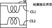
对于用于间接连接逆变器电路的方法,如图1(b)的虚线部分M中所示的,将自激励振荡中不使用的绕组直接连接在一起的配置是简单和方便的方法,因为它可以在不增加部件数量的情况下实现,但是,根据本实施例的“间接连接方法”不限于图1(b)所示的方法。虚线部分M中可使用的其它方法包括如图1(c)所示的通过变压器耦合以利用其电感效应的配置(经由变压器耦合),或者如图1(d)所示,并联到自激励振荡中不使用的三级绕组的线圈CL1和CL2被设置成相互接近的配置(线圈接近)。这些配置也包含在本发明的范围之内。As for the method for indirectly connecting the inverter circuit, as shown in the dotted line part M of Fig. 1(b), a configuration in which windings not used in self-excited oscillation are directly connected together is a simple and convenient method because It can be realized without increasing the number of components, however, the "indirect connection method" according to the present embodiment is not limited to the method shown in FIG. 1(b). Other methods that can be used in the dashed part M include the configuration (via transformer coupling) via transformer coupling to take advantage of its inductive effect as shown in Figure 1(c), or parallel to the self-excited oscillator as shown in Figure 1(d) The coils CL1 and CL2 of the tertiary winding which are not used in the coil are arranged in a mutually adjacent configuration (coil proximity). These configurations are also included in the scope of the present invention.
此外,间接连接逆变器电路的方法可以是使用同相或反相的连接的一种,只要该配置使得彼此反相的电压施加于荧光管的两端。但是,考虑到电子部件和电路设计(诸如逆变器板的线路图案)的共同性,或者对计算变压器的电或磁噪声的测量的影响,反相连接是优选的,因为这样可以获得以上的效果并降低这种影响。In addition, the method of indirectly connecting the inverter circuit may be one using in-phase or anti-phase connection as long as the configuration is such that voltages in opposite phases to each other are applied to both ends of the fluorescent tubes. However, in consideration of the commonality of electronic components and circuit design (such as the wiring pattern of the inverter board), or the influence on the measurement of the calculation of the electrical or magnetic noise of the transformer, the reverse connection is preferable, because it can obtain the above effect and reduce this effect.
如果分别施加到荧光管15和16上的高电压交流电压彼此反相,则源自每个荧光管的辐射噪声可以彼此抵消,因此能降低噪声。即使在被驱动的荧光管的数目大于两个时也可以应用上述原理,且这种情况也在本发明的范围之内。If the high-voltage AC voltages respectively applied to the
对于将逆变器变压器连接到荧光管15和16的方法,例如,在荧光管15经由逆变器变压器2和4连接且荧光管16经由逆变器变压器3和5连接的情况中,存在如下情况:即使两个荧光管15和16的规格和性能相同,每一个的亮度也是不同的。这是因为荧光管15通过具有自激励振荡中不使用的三级绕组L3-1和L3-1’的逆变器变压器连接,而荧光管16通过具有自激励振荡中使用的三级绕组L3-2和L3-2’的逆变器变压器连接。更特别地,由于根据其三级绕组是否用于自激励振荡中,施加到逆变器变压器上的功率不同,所以有时分别施加到荧光管15和16上的功率会不同。As for the method of connecting the inverter transformer to the
因此,根据本实施例,通过采用荧光管15和16以及连接到管两端的逆变器变压器2、5、3和4的以下组合,一种方法能使施加到两个荧光管15和16上的功率相等。这样,如图1(a)所示,荧光管15的一端连接到具有逆变器电路A的自激励振荡中不使用的三级绕组L3-1的逆变器变压器2的次级绕组L2-1,而荧光管15的另一端连接到具有逆变器电路B的自激励振荡中使用的三级绕组L3-2’的逆变器变压器5的次级绕组12-1’。同样,为荧光管16提供了具有逆变器变压器的类似组合(参考图1(a))。Therefore, according to the present embodiment, by using the following combination of the
通过选择如上所述的荧光管15和16以及两个逆变器变压器的组合,在方向上调节施加到两个荧光管15和16的功率,从而使它们相等。因此,如果这两个荧光管具有相同的规格和性能,亮度将粗略地相等,因此例如在使用根据本实施例的荧光管照明装置来照明背光装置时,可改善亮度的不一致。By selecting the combination of the
此外,根据本实施例的荧光管照明装置启用逆变器电路的间接连接,此外,它还使得一个逆变器电路的噪声能够方便地传播到另一个逆变器电路。例如,当采用用于根据负载(duty)变暗系统进行变暗的装置时,在一个逆变器电路的激活时发出的波纹噪声被传播到另一个逆变器电路,因此产生更高电压和更高电流的波纹噪声。In addition, the fluorescent tube lighting device according to the present embodiment enables indirect connection of inverter circuits, and furthermore, it enables noise of one inverter circuit to be easily propagated to another inverter circuit. For example, when a device for dimming a duty dimming system is employed, ripple noise emitted at the activation of one inverter circuit is propagated to the other inverter circuit, thus generating higher voltage and Ripple noise at higher currents.
因此,在根据本实施例的荧光管照明装置中,较佳地,自激励振荡中不使用的三级绕组的匝数可少于自激励振荡中使用的三级绕组的匝数。在自激励振荡中使用的三级绕组中,通常必需生成最大值约几伏的交流电动势,从而晶体管的基极(或栅极)进入ON状态。但是,在自激励振荡中不使用的三级绕组中,不必生成这种较大的电动势,且如果匝数正好约0.5匝,也可以实现其功能。即使用电流变压器设计技术可以制造该匝数,因此足够可以实现间接连接的逆变器电路的功能。此外,由于本方法允许施加到三级绕组L3-1和L3-2’的电压是低电压,所以作为降低施加到逆变器变压器的三级绕组L3-1和L3-1’的功率的方法,这也是有效的。因此,可以将荧光管照明装置内产生的电压或电流噪声抑制到最小,同时,也可以使施加到逆变器电路之间的间接连接的功率最小。Therefore, in the fluorescent tube lighting device according to the present embodiment, preferably, the number of turns of the tertiary winding not used in the self-excited oscillation may be less than the number of turns of the tertiary winding used in the self-excited oscillation. In a tertiary winding used in self-excited oscillation, it is generally necessary to generate an AC electromotive force of about several volts at maximum so that the base (or gate) of the transistor enters the ON state. However, in the tertiary winding which is not used in self-excited oscillation, it is not necessary to generate such a large electromotive force, and its function can be realized if the number of turns is exactly about 0.5 turns. That number of turns can be fabricated using current transformer design techniques and is therefore sufficient to realize the functionality of an indirectly connected inverter circuit. In addition, since this method allows the voltage applied to the tertiary windings L3-1 and L3-2' to be low voltage, as a method of reducing the power applied to the tertiary windings L3-1 and L3-1' of the inverter transformer , which is also valid. Therefore, voltage or current noise generated within the fluorescent tube lighting device can be suppressed to a minimum, and at the same time, power applied to an indirect connection between inverter circuits can also be minimized.
此外,对于逆变器电路,如上所述,存在如下情况:在电路自身内产生噪声,特别是,源自逆变器变压器2到5的磁场可能对其它电子部件(诸如液晶板)产生源自噪声的反作用。In addition, with the inverter circuit, as described above, there are cases where noise is generated within the circuit itself, and in particular, the magnetic field originating from the
因此,根据本实施例的荧光管照明装置的特点在于:为了控制发生于每个逆变器电路A和B中的噪声,使得两个逆变器变压器2和3的次级绕组L2的输出彼此反相。特别是,对于图1(a),可以想象一种方法,借此,并联的逆变器变压器2和3的初级绕组L1彼此相反地缠绕,初级绕组L1的两端子被彼此切换和连接,或者次级绕组彼此相反地缠绕。Therefore, the fluorescent tube lighting device according to the present embodiment is characterized in that the outputs of the secondary windings L2 of the two
如上所述,根据本实施例的荧光管照明装置,还可以减少由一个逆变器电路给另一个逆变器电路的噪声,减少整个荧光管照明装置的噪声,因此还可减轻给其它电子部件带去的噪声等的反作用。对于本实施例中的逆变器变压器的规格,没有特别的限制条件,例如实施例不将核心的设计限制于封闭磁型或者开口磁型。As described above, according to the fluorescent tube lighting device of the present embodiment, it is also possible to reduce the noise from one inverter circuit to another inverter circuit, reduce the noise of the entire fluorescent tube lighting device, and thus also reduce the noise to other electronic components. Reaction of the noise etc. taken away. There are no special restrictions on the specifications of the inverter transformer in this embodiment, for example, the embodiment does not limit the design of the core to the closed magnetic type or the open magnetic type.
图1(a)所示的逆变器电路仅仅是基本配置,且已相对于本实施例添加大量修改或改善的逆变器电路将实现类似的功能。例如,已添加诸如变暗电路或检测附随灯故障等的错误的电路的附加功能的情况,或者对逆变器电路进行修改从而在变暗时仅一个晶体管8和9的基极端子连接到输入端子1以降低振荡噪声的情况,都在本发明的范围之内。The inverter circuit shown in FIG. 1( a ) is only a basic configuration, and an inverter circuit to which a large number of modifications or improvements have been added relative to this embodiment will achieve similar functions. For example, the case where additional functionality has been added such as a dimming circuit or a circuit to detect errors accompanying lamp failure etc., or the inverter circuit is modified so that only one
接着,将参考图1(e)描述根据本发明的修改实例的荧光管照明装置。图1(e)示出了在荧光管照明装置中使用1输入、2输出逆变器变压器(以下称作“2合1变压器”)的情况的配置实例。逆变器变压器2和3都具有两个三级绕组,其中一个用作自激励振荡中使用的三级绕组L3-2和L3-2’而另一个用作自激励振荡中不使用的三级绕组L3-1和L3-1’。Next, a fluorescent tube lighting device according to a modified example of the present invention will be described with reference to FIG. 1( e ). FIG. 1( e ) shows a configuration example of a case where a 1-input, 2-output inverter transformer (hereinafter referred to as "2-in-1 transformer") is used in a fluorescent tube lighting device. Both
如图1(e)所示,根据本实施例的修改实例的荧光管照明装置的主要部件是两个逆变器电路A和B以及荧光管15和16。逆变器电路A和B包括直流电源输入端子1(1a,1b)、逆变器变压器2和3、扼流圈6和7、晶体管8到11、共振电容器12和13以及作为滤波器的电容器14。在这些部件中,逆变器变压器2和3被配置成包括初级绕组L1和L1’、两个次级绕组L2-1、L2-1’、L2-2和L2-2’以及两个三级绕组L3-1和L3-2(L3-1’和L3-2’)。根据本修改实例的荧光管照明装置使用L3-2和L3-2’作为自激励振荡中使用的三级绕组并使用L3-1和L3-1’作为自激励振荡中不使用的三级绕组。As shown in FIG. 1( e ), the main components of the fluorescent tube lighting device according to the modified example of the present embodiment are two inverter circuits A and B and
具有这种配置的荧光管照明装置具有同图1(a)所示的荧光管照明装置的配置相类似的优点。A fluorescent tube lighting device having such a configuration has similar advantages to the configuration of the fluorescent tube lighting device shown in FIG. 1(a).
根据以上电路,由于交流波形没有波形畸变且可以将足够的高电压施加到荧光管15和16,所以可以稳定地驱动荧光管。According to the above circuit, since the AC waveform has no waveform distortion and a sufficiently high voltage can be applied to the
此外,根据本实施例的荧光管照明装置,通过使得逆变器变压器2和3的自激励振荡中不使用的三级绕组L3-1和L3-1’的匝数小于自激励振荡中使用的三级绕组L3-2和L3-2’的匝数,还可以减少一个逆变器电路给予另一个逆变器电路的噪声。此外,通过将逆变器变压器2和3中每一个的两个次级绕组L2-1和L2-2设计为具有彼此相反绕组,源自彼此反相驱动的荧光管15和16的辐射噪声相互抵消以减少整个荧光管照明装置的噪声,因此还可以减轻给予其它电子部件的噪声等的反作用。Furthermore, according to the fluorescent tube lighting device of the present embodiment, by making the number of turns of the tertiary windings L3-1 and L3-1' not used in the self-excited oscillation of the
作为用于间接连接逆变器电路的方法,同图1(a)的情况类似,如图1(b)的虚线部分M所示,将自激励振荡中不使用的绕组直接连接在一起的配置是简单和方便的方法,因为它可以在不增加部件数量的情况下实现,但是根据本实施例的“间接连接方法”不限于图1(b)所示的方法。可用于虚线部分M中的其它方法包括通过变压器以利用其电感效应耦合的配置,如图1(c)所示,或者将并联到自激励振荡中不使用的三级绕组的线圈CL1和CL2设置成相互接近的配置,如图1(d)所示。这些配置也包含于本发明的范围之内。As a method for indirectly connecting the inverter circuit, similar to the case of Fig. 1(a), as shown in the dotted line part M of Fig. 1(b), a configuration in which windings not used in self-excited oscillation are directly connected together is a simple and convenient method because it can be realized without increasing the number of parts, but the "indirect connection method" according to the present embodiment is not limited to the method shown in FIG. 1(b). Other methods that can be used in the dotted part M include the configuration of coupling through a transformer to take advantage of its inductive effect, as shown in Fig. into a configuration close to each other, as shown in Figure 1(d). These configurations are also included in the scope of the present invention.
在本实施例中,两个三级绕组L3-1和L3-2设置于一个逆变器变压器中,但是,这种绕组的数量不限于两个,如必要可以提供三个或更多。(详情参考第五实施例(图5(c))。In this embodiment, two tertiary windings L3-1 and L3-2 are provided in one inverter transformer, however, the number of such windings is not limited to two, and three or more may be provided if necessary. (Refer to the fifth embodiment (FIG. 5(c)) for details.
接着,将参考图2(a)到2(d)描述根据本发明第二实施例的荧光管照明装置。Next, a fluorescent tube lighting device according to a second embodiment of the present invention will be described with reference to FIGS. 2(a) to 2(d).
图2(a)示出了根据本发明的荧光管照明装置的第二实施例的主要电路图。逆变器变压器中使用的变压器是2合1变压器,且为了将彼此反相的电压施加到荧光管的两端,管两端分别连接到逆变器变压器的一端。此外,对于每个逆变器电路的自激励振荡中使用的三级绕组,通过分别并联设置的线圈等将绕组彼此连接,可间接地连接这两个逆变器电路。Fig. 2(a) shows the main circuit diagram of the second embodiment of the fluorescent tube lighting device according to the present invention. The transformer used in the inverter transformer is a 2-in-1 transformer, and in order to apply voltages in opposite phases to each other to both ends of the fluorescent tube, both ends of the tube are respectively connected to one end of the inverter transformer. Furthermore, for the three-level windings used in the self-excited oscillation of each inverter circuit, the two inverter circuits can be indirectly connected by connecting the windings to each other through coils or the like respectively provided in parallel.
图2(a)的主要部件是两个逆变器电路A和B以及荧光管15和16。逆变器电路A和B包括直流电压输入端子1a、2合1逆变器变压器2和3、扼流圈5和6、晶体管8、9、8’和9’、共振电容器11和12、用作滤波器14的电容器等等。在这些部件中,逆变器变压器2和3包括初级绕组L1和L1’、次级绕组L2-1、L2-1’、L2-2和L2-2’以及三级绕组L3-1、L3-1’、L3-2和L3-2’。此外,在本实施例中,L3-2和L3-2’用作自激励振荡中使用的三级绕组。The main components of FIG. 2( a ) are two inverter circuits A and B and
在根据本实施例的荧光管照明装置中,作为用于间接耦合逆变器电路A和B的装置,几个实施例可被叙述为虚线部分M内的配置实例。本实施例的特点在于,从逆变器电路A和B的自激励振荡中使用的每个三级绕组L3-2和L3-2’分接的两个端子经由线圈或变压器并联。更特别的配置实例包括在虚线部分M内通过变压器的两个绕组L4和L4’进行连接的配置(通过变压器耦合),如图2(b)所示。In the fluorescent tube lighting device according to the present embodiment, as means for indirectly coupling the inverter circuits A and B, several embodiments can be described as configuration examples within the dotted line portion M. The present embodiment is characterized in that two terminals tapped from each of the tertiary windings L3-2 and L3-2' used in the self-excited oscillations of the inverter circuits A and B are connected in parallel via a coil or a transformer. A more specific configuration example includes a configuration in which two windings L4 and L4' of a transformer are connected within the dotted line part M (via transformer coupling), as shown in Fig. 2(b).
此外,如图2(c)所示,也可采用通过两个变压器连接的配置。将采用线性延伸的直管型荧光管作为实例说明如图2(c)所示使用两个变压器的优点。在仅使用一个变压器的情况中,如在图2(b)中,变压器仅被装配在逆变器A和B中的一个中,且因为逆变器A的功率和逆变器B的功率不相等,亮度差易于在荧光管的两端之间产生。但是,通过如图2(c)所示使用两个变压器,逆变器A和B可各配备一个变压器,因此可以相等地将功率分配给这两个逆变器电路A和B,使得荧光管的左侧和右侧的亮度平衡能得以维持。此外,在根据本实施例的两个变压器中,通过使得输出侧的绕组L5和L5’的匝数少于输入侧的绕组L4和L4’的匝数,会降低施加到输出绕组L5和L5’上的电压(图2(c))。这使得每个逆变器电路A和B中承受的电压分量中的过量噪声分量能最小化。此外,通过采用输入侧和输出侧的绕组L4、L5、L4’和L5’中的任一个相对于另一个相反缠绕的配置,源于每个变压器中的噪声分量被相互抵消,从而能稳定地振荡逆变器电路A和B。In addition, as shown in Fig. 2(c), a configuration connected through two transformers is also available. The advantage of using two transformers as shown in Fig. 2(c) will be explained by taking a linearly extending straight fluorescent tube as an example. In the case of using only one transformer, as in Fig. 2(b), the transformer is installed in only one of inverters A and B, and since the power of inverter A and the power of inverter B are not equal, a brightness difference tends to be generated between the two ends of the fluorescent tube. However, by using two transformers as shown in Fig. 2(c), inverters A and B can each be equipped with a transformer, so that the power can be equally distributed to the two inverter circuits A and B, so that the fluorescent tube The brightness balance of the left and right sides can be maintained. Furthermore, in the two transformers according to the present embodiment, by making the windings L5 and L5' on the output side have fewer turns than the windings L4 and L4' on the input side, the voltage applied to the output windings L5 and L5' is reduced. The voltage on (Fig. 2(c)). This enables excessive noise components in the voltage components experienced in each of the inverter circuits A and B to be minimized. In addition, by employing a configuration in which any one of the windings L4, L5, L4', and L5' on the input side and output side is wound oppositely with respect to the other, noise components originating in each transformer are canceled out mutually, thereby enabling stable Oscillating inverter circuits A and B.
此外,如图2(d)所示,用于变压器2和3的自激励振荡的绕组可分别并联到线圈CL4和CL4’,且线圈CL4和CL4’可简单地设置为相互接近(线圈接近)。根据这种配置,通过源于线圈CL4和CL4’的核心的磁场,调谐施加到线圈CL4和CL4’上的感生电动势的电压相位,且因为如同根据第一实施例的荧光管照明装置,施加到荧光管两端上的交流彼此反相地驱动,使得荧光管两端能够进行驱动。In addition, as shown in Fig. 2(d), the windings for the self-excited oscillations of the
在期望彼此反相地驱动逆变器电路A和B的情况中,如图2(b)所示,可通过相反绕组连接并联到每一个的自激励振荡中使用的三级绕组的绕组(L4或L4’)。从而,可以简单地驱动两端同时实现逆变器电路A和B的部件配置和线路图案的共同性。In the case where it is desired to drive the inverter circuits A and B in antiphase to each other, as shown in FIG. 2(b), the winding (L4 or L4'). Thus, both ends can be driven simply while achieving commonality of component configurations and wiring patterns of the inverter circuits A and B.
此外,与根据本发明第一实施例的荧光管照明装置相类似,可以配置电路以使每个逆变器电路内的逆变器变压器的两个输出彼此反相。此外,采用1合1变压器作为逆变器变压器的情况也在本发明的范围之内。在这种情况中,连接到荧光管两端的逆变器变压器可以是含自激励振荡中使用的三级绕组的一个以及含自激励振荡中不使用的三级绕组的一个之间的组合。通过采用这种配置,可发挥同根据以上第一实施例的荧光管照明装置的情况相同的效果。Furthermore, similarly to the fluorescent tube lighting device according to the first embodiment of the present invention, circuits may be configured such that the two outputs of the inverter transformer within each inverter circuit are in inverse phase with each other. In addition, the case of using a 1-in-1 transformer as an inverter transformer is also within the scope of the present invention. In this case, the inverter transformer connected to both ends of the fluorescent tube may be a combination between one including a tertiary winding used in self-excited oscillation and one including a tertiary winding not used in self-excited oscillation. By employing such a configuration, the same effects as in the case of the fluorescent tube lighting device according to the above first embodiment can be exerted.
接着,将参考附图说明根据本发明第三实施例的荧光管照明装置。图3(a)说明了根据本实施例的荧光管照明装置的配置实例。图3(a)所示的配置的特点在于,具有作为用于两个逆变器电路A和B同步的装置的第一配置,在该第一配置中设置于输入端子1a和从初级绕组L1与L1’分接的中心抽头CT1和CT2之间的扼流圈(图中未示出)间接地连接在一起且该间接连接被配置成使得逆变器A和B彼此反相地驱动;以及第二配置,在该第二配置中逆变器电路A和B内的次级绕组L2-1和L2-1’以及L2-2和L2-2’分别彼此相反缠绕。因此,抵消了核心的磁场。Next, a fluorescent tube lighting device according to a third embodiment of the present invention will be described with reference to the drawings. Fig. 3(a) illustrates a configuration example of the fluorescent tube lighting device according to the present embodiment. The configuration shown in Fig. 3(a) is characterized by having a first configuration as a means for synchronizing the two inverter circuits A and B, in which the input terminal 1a and the slave primary winding L1 choke coils (not shown) between center taps CT1 and CT2 tapped from L1' are indirectly connected together and the indirect connection is configured such that inverters A and B are driven in antiphase to each other; and A second configuration in which the secondary windings L2-1 and L2-1' and L2-2 and L2-2' in the inverter circuits A and B are respectively wound opposite to each other. Thus, the magnetic field of the core is canceled out.
通过在根据本实施例的荧光管照明装置中包含以上的第一配置,可使施加到荧光管两端上的电压彼此反相而不用增加部件数量(简单配置)。此外,通过以上的第二配置,消除了核心中产生的磁场。By including the above first configuration in the fluorescent tube lighting device according to the present embodiment, the voltages applied to both ends of the fluorescent tubes can be made to invert each other without increasing the number of parts (simple configuration). Furthermore, with the above second configuration, the magnetic field generated in the core is eliminated.
对于根据本发明实施例的其它修改实例的荧光管照明装置,四种配置实例可用于虚线部分M内的配置,用作间接耦合逆变器电路A和B的装置。这四种配置实例的特点是:包括作为用于逆变器A和B同步的装置的配置,它为每个中心抽头将扼流圈间接地连接在一起从而它们相互关联以启用同步。For fluorescent tube lighting devices according to other modified examples of the embodiment of the present invention, four configuration examples are available for the configuration within the dotted line portion M as a device that indirectly couples inverter circuits A and B. These four configuration examples are characterized by the configuration that includes, as a means for inverter A and B synchronization, the choke coils connected together indirectly for each center tap so that they correlate to enable synchronization.
更特别地,间接连接配置的实例是如图3(b)所示的线圈接近类型配置,它是通过将线圈CL1和CL2设置成在虚线部分M内相互接近而实现的(线圈接近型)。此外,如图3(c)所示,包括通过变压器间接连接逆变器电路的变压器的配置也是可以的。根据该配置,可以从具有两个线圈的图3(b)的配置减少部件数量成为具有一个变压器的配置。此外,如图3(d)所示,通过两个变压器T1和T2连接逆变器电路的配置也是可以的。图3(d)所示的配置(通过变压器耦合)提供了一优点,例如在逆变器电路A和B彼此成一定距离以点亮直管型荧光管的情况中,其中如果逆变器A和B中的任一个具有一个变压器,则会损失这两个逆变器之间的功率平衡且荧光管两端的亮度会变得不相等。在这种情况中,通过使用两个变压器以便在这两个逆变器的每一个中提供一个变压器,则可以将功率相等地分配给这两个变压器A和B,且可以维持荧光管的右侧和左侧之间的亮度平衡。因此,图3(d)所示的配置表示在驱动线性延伸的直管型灯两端的情况下的其技术效果。More specifically, an example of an indirect connection configuration is a coil proximity type configuration as shown in FIG. 3( b ), which is realized by arranging coils CL1 and CL2 close to each other within a dotted line portion M (coil proximity type). In addition, as shown in FIG. 3(c), a configuration including a transformer indirectly connected to an inverter circuit through a transformer is also possible. According to this configuration, it is possible to reduce the number of components from the configuration of FIG. 3( b ) having two coils to a configuration having one transformer. In addition, as shown in FIG. 3(d), a configuration in which an inverter circuit is connected through two transformers T1 and T2 is also possible. The configuration shown in Fig. 3(d) (coupled by a transformer) provides an advantage, for example, in the case where the inverter circuits A and B are at a distance from each other to light straight fluorescent tubes, where if the inverter A If either of A and B has a transformer, the power balance between the two inverters is lost and the brightness across the fluorescent tubes becomes unequal. In this case, by using two transformers so that one transformer is provided in each of the two inverters, power can be equally distributed to the two transformers A and B, and the right Brightness balance between side and left. Therefore, the configuration shown in FIG. 3( d ) represents its technical effect in the case of driving both ends of a linearly extending straight tube type lamp.
此外,对于根据本实施例的两个变压器,通过使得输出侧绕组L5’的匝数少于输入侧绕组L4’的匝数,就可以降低施加到输出绕组L5’上的电压,使得输送到两个逆变器电路A和B的电压分量中的过量噪声分量最小。此外,通过采用一配置以使输入侧和输出侧之间的绕组彼此相反缠绕,源于每个变压器的噪声分量彼此抵消,使其能稳定地振荡逆变器电路A和B两者。In addition, for the two transformers according to this embodiment, by making the number of turns of the output side winding L5' less than the number of turns of the input side winding L4', the voltage applied to the output winding L5' can be reduced, so that the voltage supplied to the two The excess noise components in the voltage components of the two inverter circuits A and B are minimized. Furthermore, by employing a configuration such that the windings between the input side and the output side are wound opposite to each other, the noise components originating from each transformer cancel each other out, making it possible to stably oscillate both inverter circuits A and B.
此外,使用图3(e)所示的配置类型,可以减少间接连接中使用的绕组并通过弱电感耦合进行耦合。在图3(e)所示的配置中,两个绕组CL31和CL41形成一对,以构成变压器。通过采用这种配置,可进行同步同时使得每个变压器电路中生成的噪声最小。Furthermore, using the type of configuration shown in Fig. 3(e), it is possible to reduce the number of windings used in the indirect connection and couple through weak inductive coupling. In the configuration shown in FIG. 3( e ), two windings CL31 and CL41 form a pair to constitute a transformer. By adopting this configuration, synchronization can be performed while minimizing noise generated in each transformer circuit.
间接连接逆变器电路的方法可以是反相方法或同相方法,只要该配置将反相电压施加到荧光管两端,且这些方法包含在本发明的范围之内。The method of indirectly connecting the inverter circuit may be an inverting method or a non-inverting method as long as the configuration applies a reverse voltage to both ends of the fluorescent tubes, and these methods are included in the scope of the present invention.
接着,将参考附图描述根据本发明第四实施例的荧光管照明装置。图4说明了根据本实施例的荧光管照明装置的配置实例,针对使用2合1变压器的情况。如图4所示,根据本实施例的荧光管照明装置具有通过含初级绕组L1’和L3’的降压变压器3和5间接连接逆变器A和逆变器B的配置。Next, a fluorescent tube lighting device according to a fourth embodiment of the present invention will be described with reference to the drawings. FIG. 4 illustrates a configuration example of the fluorescent tube lighting device according to the present embodiment, for the case of using a 2-in-1 transformer. As shown in FIG. 4, the fluorescent tube lighting device according to the present embodiment has a configuration in which inverter A and inverter B are indirectly connected through step-down transformers 3 and 5 including primary windings L1' and L3'.
在逆变器A和B中,其中降压变压器3和5(其中来自次级绕组的电压小于初级绕组的电压)的初级绕组L1’和L3’分别并联到逆变器变压器(升压变压器)的初级绕组L1和L3。变压器3和5由初级绕组L1’和L3’以及次级绕组L2-2和L2-2’构成以降低来自每个初级绕组的电压。该实施例的特点在于,次级绕组L2-2和L2-2’间接或直接地相互连接。In inverters A and B, where step-down transformers 3 and 5 (where the voltage from the secondary winding is less than the voltage of the primary winding) primary windings L1' and L3' are connected in parallel to the inverter transformer (step-up transformer) respectively primary windings L1 and L3. The transformers 3 and 5 are composed of primary windings L1' and L3' and secondary windings L2-2 and L2-2' to step down the voltage from each primary winding. This embodiment is characterized in that the secondary windings L2-2 and L2-2' are connected to each other indirectly or directly.
在根据本实施例的荧光管照明装置中,作为用于间接连接的装置,包含分别从逆变器电路A和B分接的一部分振荡电路的变压器通过含初级绕组L1’和L3’的变压器3和5的次级绕组L2-2和L2-2’间接连接。更特别地,采用一配置,从而含初级绕组L1’和L3’的变压器3和5的次级绕组L2-2和L2-2’被连接,从而逆变器电路A和B的相位被彼此倒相。这样,本修改实例的特点在于变压器的次级绕组(它基本是连接到荧光管两端以提升电压的装置)不用于荧光管的电源中而用于间接连接。In the fluorescent tube lighting device according to the present embodiment, as means for indirect connection, a transformer including a part of an oscillation circuit tapped from inverter circuits A and B respectively passes through a transformer 3 including primary windings L1' and L3' And 5's secondary windings L2-2 and L2-2' are indirectly connected. More specifically, a configuration is adopted so that the secondary windings L2-2 and L2-2' of the transformers 3 and 5 including the primary windings L1' and L3' are connected so that the phases of the inverter circuits A and B are inverted to each other Mutually. Thus, this modified example is characterized in that the secondary winding of the transformer (which is basically a device connected to both ends of the fluorescent tube to boost the voltage) is not used in the power supply of the fluorescent tube but used for indirect connection.
通过采用以上配置,在降压变压器3和5的初级绕组L1’和L3’的每一个中,同升压变压器2和4的初级绕组L1和L3相类似,根据晶体管8-11的开关状态,从中心抽头CT1’和CT2’流出的电流方向不断振荡,且通过作为其结果形成的变压器核心的磁通量波动,在降压变压器3和5的次级绕组L2-2和L2-2’中生成交流波形。因此,通过将图4所示的这两个次级绕组耦合在一起,逆变器电路的相位被彼此反相地同步且在升压变压器2和4的次级绕组L2-1和L2-1’中生成反相的高电压。因此,通过将这两个端子连接到荧光管15两端,可以以稳定频率驱动荧光管15。相同的原理可应用于荧光管16。By adopting the above configuration, in each of the primary windings L1' and L3' of the step-down transformers 3 and 5, similarly to the primary windings L1 and L3 of the step-up
根据以上配置,由于执行操作以使升压变压器2的初级绕组L1中经由中心抽头CT1流动的电流方向同升压变压器4的初级绕组L3中经由中心抽头CT2流动的电流方向相反,彼此反相的交流可生成于同相缠绕的升压变压器2的次级绕组L2-1和升压变压器4的次级绕组L2-1’之间,而不在其电压波形中产生畸变。According to the above configuration, since the operation is performed so that the direction of the current flowing in the primary winding L1 of the step-up
因此,当在荧光管15和16的两端处提供一对逆变器电路并并联驱动荧光管时,因为与荧光管连接的每个逆变器电路的次级绕组中生成的电压可彼此反相地同步,可以按相同大小将差分电压施加到每个荧光管两端,从而即使对于较长的荧光管,也可使亮度相等。Therefore, when a pair of inverter circuits are provided at both ends of the
在以上实例中,次级绕组用于将降压变压器连接在一起,但是降压变压器可进一步配备一反馈绕组(三级绕组),以及连接在一起的多个反馈绕组。In the above example, the secondary windings are used to connect the step-down transformer together, but the step-down transformer can be further equipped with a feedback winding (tertiary winding), and multiple feedback windings connected together.
如上所述,将降压变压器3和5的次级绕组耦合在一起的方法不限于直接连接,且可通过线圈或变压器等可进行耦合,这些方法都在本发明的范围之内。As mentioned above, the method of coupling the secondary windings of the step-down transformers 3 and 5 is not limited to direct connection, and can be coupled through coils or transformers, etc., and these methods are within the scope of the present invention.
此外,间接连接逆变器电路的方法可包括同相或反相的连接,只要该配置使得彼此反相的电压施加到荧光管的两端,且这种方法包含在本发明的范围之内。In addition, the method of indirectly connecting the inverter circuit may include in-phase or anti-phase connection as long as the configuration is such that voltages in opposite phases to each other are applied to both ends of the fluorescent tubes, and such a method is included in the scope of the present invention.
接着,将参考图5(a)到5(d)说明根据本发明第五实施例的荧光管照明装置。根据本实施例的荧光管照明装置的特点在于,具有使用用于荧光管两端处的逆变器电路的间接连接的装置的第一配置以及使用用于荧光管照明装置的间接连接的装置的第二配置。Next, a fluorescent tube lighting device according to a fifth embodiment of the present invention will be described with reference to FIGS. 5(a) to 5(d). The fluorescent tube lighting device according to the present embodiment is characterized by having the first configuration using the device for indirect connection of the inverter circuit at both ends of the fluorescent tube and using the device for indirect connection of the fluorescent tube lighting device Second configuration.
在如图5(a)所示的荧光管照明装置中,以上第一和第二配置如下。那么,作为用于荧光管两端处逆变器电路之间的间接连接的装置的第一配置表示装置LN1或LN2,通过设置为面向前述绕组的绕组,其连接具有并联到逆变器电路A或B的自激励振荡中使用的三级绕组的绕组的变压器71或73以及具有类似地并联到逆变器电路C或D的自激励振荡中使用的三级绕组的绕组的变压器75或77。此时,使用用于荧光管照明装置的间接连接的装置的第二配置包括将逆变器电路A和B的自激励振荡中不使用的三级绕组两端连接在一起的装置LN3以及将逆变器电路C和D的自激励振荡中不施用的三级绕组两端连接在一起的装置LN4中的至少一个。In the fluorescent tube lighting device as shown in Fig. 5(a), the above first and second configurations are as follows. Then, the first configuration as means for indirect connection between the inverter circuits at both ends of the fluorescent tube represents the means LN1 or LN2, the connection of which has a parallel connection to the inverter circuit A by being arranged to face the winding of the aforementioned winding A transformer 71 or 73 with a winding of the tertiary winding used in self-excited oscillation of the inverter circuit C or D and a transformer 75 or 77 similarly connected in parallel to the winding of the tertiary winding used in the self-excited oscillation of the inverter circuit C or D. At this time, the second configuration using the means for indirect connection for fluorescent tube lighting includes means LN3 connecting both ends of the tertiary windings not used in the self-excited oscillations of the inverter circuits A and B together and connecting the inverter circuits A and B to each other. At least one of the means LN4 connecting both ends of the tertiary windings not applied in the self-excited oscillations of the inverter circuits C and D.
对于以上第一配置的LN1或LN2的连接方法,该连接可以是进行驱动,从而逆变器电路A和C或者B或D的相位彼此同相或反相,只要它们被连接成使得施加到每一个荧光管51-54的两端的电压彼此反相。For the connection method of LN1 or LN2 of the first configuration above, the connection may be driven so that the phases of the inverter circuits A and C or B or D are in phase with or out of phase with each other, as long as they are connected so that the phases applied to each The voltages across the fluorescent tubes 51-54 are opposite to each other.
对于以上第二配置的LN3或LN4的连接方法,该连接可以是进行驱动,从而逆变器电路A和B的相位彼此同相或反相,且较佳地,该连接是施加到荧光管51到54的交流电压的相位经单个荧光管或经单个荧光管照明装置的荧光管数目而被倒相。更特别地,例如在施加到单个荧光管照明装置内的荧光管51和52上的交流电压的相位彼此反相的情况下,如果用于间接连接的装置LN3或LN4被连接,以使逆变器电路A和B或者C和D被同相驱动,则施加到荧光管51到54上的交流电压的相位总是经单个荧光管而被倒相。相反,当施加到单个荧光管照明装置内的荧光管51和52上的交流电压的相位彼此反相时,如果用于间接连接的装置LN3或LN4被连接,以使逆变器电路A和B或者C和D被反相驱动,则施加到荧光管51到54上的交流电压的相位经单个荧光管照明装置的荧光管数量而被倒相。通过按这种方式经单个荧光管或者经单个荧光管照明装置的荧光管数量而使施加到荧光管上的交流电压相位倒相,可以使荧光管产生的不需要的辐射噪声相抵,从而可以提供具有较低噪声的荧光管照明装置。For the connection method of LN3 or LN4 of the second configuration above, the connection may be driven so that the phases of the inverter circuits A and B are in phase with or opposite to each other, and preferably, the connection is applied to the
除了以上的方法,作为用于顺序地将施加到荧光管上的交流电压相位倒相的特殊方法,以下的方法也是可以的,其中为每个次级绕组顺序地交换到变压器的次级绕组的荧光管的连接端子以及接地端子。因此,对于用于使荧光管的相位倒相的以上装置,将每个逆变器电路A到D的两个次级绕组L2-1和L2-2彼此相反缠绕的方法不总是必要的,且可以使用在相同方向上缠绕绕组的方法,且这种方法也在本发明的范围之内。In addition to the above method, as a special method for sequentially inverting the phase of the AC voltage applied to the fluorescent tube, the following method is also possible, in which for each secondary winding is sequentially switched to the secondary winding of the transformer Fluorescent tube connection terminal and ground terminal. Therefore, the method of winding the two secondary windings L2-1 and L2-2 of each inverter circuit A to D opposite to each other is not always necessary for the above means for inverting the phase of the fluorescent tube, And a method of winding the windings in the same direction can be used, and this method is also within the scope of the present invention.
对于用于间接连接的装置LN1到LN4,只要提供了用于间接连接的一个装置,因为可以同步逆变器电路A到D,如果缺少任何其它装置,也不会出现问题,且可使用一配置,如必要包括所有四个连接装置,以便增强逆变器电路之间的同步。As for the devices LN1 to LN4 for indirect connection, as long as one device for indirect connection is provided, since the inverter circuits A to D can be synchronized, there will be no problem if any other device is missing, and a configuration can be used , including all four connecting devices as necessary to enhance synchronization between inverter circuits.
根据具有以上配置的荧光管照明装置,例如由于可减少从荧光管行进到荧液晶板的噪声,使得申请的范围及其效果变宽和进一步增加。According to the fluorescent tube lighting device having the above configuration, for example, since noise traveling from the fluorescent tube to the fluorescent liquid crystal panel can be reduced, the range of application and its effects are broadened and further increased.
接着,将参考图5(b)描述根据本实施例的第一修改实例的荧光管照明装置。在根据本实施例的第一修改实例的荧光管照明装置中,作为用于荧光管两端处逆变器电路的间接连接的装置的第一配置表示装置LN1,它将逆变器电路A和C的自激励振荡中不使用的三级绕组的两端连接在一起,以及装置LN2,它将逆变器电路B和D的自激励振荡中不使用的三级绕组的两端连接在一起。同时,使用用作荧光管照明装置的间接连接的装置的第二配置包括装置LN3或LN4,通过被设置成面向上述绕组的绕组,它连接具有并联到逆变器电路A或C的自激励振荡中使用的三级绕组的绕组的变压器71或75以及具有类似地并联到逆变器电路B或D的自激励振荡中使用的三级绕组的绕组的变压器73或77。更特别地,该配置使得根据上述原始实施例(图5(a))的第一配置和第二配置的装置分别交换。因此,其效果同图5(a)实施例的效果相同。Next, a fluorescent tube lighting device according to a first modified example of the present embodiment will be described with reference to FIG. 5( b ). In the fluorescent tube lighting device according to the first modified example of the present embodiment, the first configuration as means for indirect connection of the inverter circuit at both ends of the fluorescent tube represents means LN1 which combines the inverter circuit A and Both ends of tertiary windings not used in self-excited oscillation of C are connected together, and means LN2 which connects both ends of tertiary windings not used in self-excited oscillation of inverter circuits B and D together. At the same time, the second configuration using the device used as indirect connection of the fluorescent tube lighting device comprises the device LN3 or LN4, which connects a self-excited oscillating The transformer 71 or 75 having the winding of the tertiary winding used in the self-excited oscillation of the inverter circuit B or D is similarly connected in parallel to the transformer 73 or 77 of the tertiary winding used in the self-excited oscillation. More particularly, this configuration enables the devices according to the first configuration and the second configuration of the above-mentioned original embodiment (FIG. 5(a)) to be exchanged, respectively. Therefore, the effect is the same as that of the embodiment of Fig. 5(a).
此外,在该第一修改实例中,如同以前的实施例,根据施加到荧光管51到54的交流电压的相位倒相情况,可进行关于是否具有用于反相或同相的间接连接操作的装置的判定,且可适当地使连接装置同相或反相操作。根据具有这种配置的荧光管照明装置,由于可以在荧光管之间相抵源于荧光管的不需要的辐射分量,所以可以减少例如从荧光行进到液晶板的噪声。Furthermore, in this first modified example, as in the previous embodiment, depending on the phase inversion of the AC voltages applied to the
对于用于间接连接的这些装置LN1到LN4,由于可以同步逆变器电路A到D,只要提供一个用于间接连接的装置,如果缺少任一个其它装置,也不会出现问题,且如必要,所采用的配置可包括所有四个连接装置,以增强逆变器电路之间的同步。As for these devices LN1 to LN4 for indirect connection, since the inverter circuits A to D can be synchronized, only one device for indirect connection is provided, and no problem occurs if any other device is lacking, and if necessary, The configuration employed may include all four connection arrangements to enhance synchronization between inverter circuits.
接着,将参考图5(c)描述根据本实施例的第二修改实例的荧光管照明装置。在根据本实施例的第二修改实例的荧光管照明装置中,在逆变器变压器中设置了三个三级绕组,且由于它们中的一个用作自激励振荡中使用的三级绕组,其余两个用作自激励振荡中不使用的三级绕组。因此,作为用于将荧光管两端处的逆变器电路间接连接在一起的第一配置以及使用用于荧光管照明装置的间接连接的装置的第二配置可使用这些自激励振荡中不使用的三级绕组。因此,作为用于将荧光管两端处的逆变器电路间接连接在一起的装置的第一配置表示装置LN1,它将逆变器电路A和C的自激励振荡中不使用的三级绕组的两端连接在一起,以及装置LN2,它将逆变器电路B和D的自激励振荡中不使用的三级绕组的两端连接在一起。同时,使用用于荧光管照明装置的间接连接的装置的第二配置包括装置LN3,它将逆变器电路A和B的自激励振荡中不使用的三级绕组的两端连接在一起,以及装置LN4,它将逆变器电路C和D的自激励振荡中不使用的三级绕组的两端连接在一起。虽然以上装置与图5(a)中的那些不同,由于用于间接连接的每个装置的用途分别同图5(a)中的那些相同,其效果同图5(a)所示实施例中的相同。Next, a fluorescent tube lighting device according to a second modified example of the present embodiment will be described with reference to FIG. 5( c ). In the fluorescent tube lighting device according to the second modified example of this embodiment, three tertiary windings are provided in the inverter transformer, and since one of them is used as a tertiary winding used in self-excited oscillation, the rest Two are used as tertiary windings which are not used in self-excited oscillation. Therefore, as the first configuration for indirectly connecting together the inverter circuits at both ends of the fluorescent tubes and the second configuration using means for the indirect connection of the fluorescent tube lighting device, it is possible to use which of these self-excited oscillations does not use of the tertiary winding. Therefore, the first configuration as a means for indirectly connecting together the inverter circuits at both ends of the fluorescent tube represents the means LN1 which connects the tertiary windings not used in the self-excited oscillations of the inverter circuits A and C Both ends of the tertiary windings not used in the self-excited oscillations of the inverter circuits B and D are connected together, and a device LN2 is connected together. Meanwhile, the second configuration using means for indirect connection for fluorescent tube lighting includes means LN3 which connects together both ends of the tertiary windings not used in the self-excited oscillations of the inverter circuits A and B, and A device LN4 which connects together both ends of the tertiary windings not used in the self-excited oscillations of the inverter circuits C and D. Although the above devices are different from those in Fig. 5(a), since the purpose of each device for indirect connection is the same as those in Fig. 5(a), its effect is the same as that in the embodiment shown in Fig. 5(a). of the same.
此外,在本第二修改实例中,如同以前的实施例,根据施加到荧光管51到54的交流电压的相位倒相情况,可进行关于是否具有用于反相或同相的间接连接操作的装置的判定,且可适当地使连接装置同相或反相操作。根据具有这种配置的荧光管照明装置,由于可以在荧光管之间相抵源于荧光管的不需要的辐射分量,所以可以减少例如从荧光行进到液晶板的噪声。Furthermore, in this second modified example, as in the previous embodiment, depending on the phase inversion of the AC voltages applied to the
对于用于间接连接的这些装置LN1到LN4,由于可以同步逆变器电路A到D,只要提供一个用于间接连接的装置,如果缺少任一个其它装置,也不会出现问题,且如必要,所采用的配置可包括所有四个连接装置,以增强逆变器电路之间的同步。As for these devices LN1 to LN4 for indirect connection, since the inverter circuits A to D can be synchronized, only one device for indirect connection is provided, and no problem occurs if any other device is lacking, and if necessary, The configuration employed may include all four connection arrangements to enhance synchronization between inverter circuits.
接着,将参考图5(d)描述根据本实施例的第三修改实例的荧光管照明装置。在根据本实施例的第三修改实例的荧光管照明装置中,作为用于将荧光管两端处的逆变器电路间接连接在一起的第一配置表示装置LN1,它将逆变器电路A和C的自激励振荡中不使用的三级绕组的两端连接在一起,以及装置LN2,它将逆变器电路B和D的自激励振荡中不使用的三级绕组的两端连接在一起。同时,使用用于荧光管照明装置的间接连接的装置的第二配置包括装置90或90’,它通过逆变器电路A和B或者C和D的扼流圈的装置执行间接连接。虽然以上装置与图5(a)中的那些不同,由于用于每个间接连接装置的用途分别同图5(a)中的那些相同(90和90’对应于LN3和LN4),其效果同图5(a)所示实施例中的相同。Next, a fluorescent tube lighting device according to a third modified example of the present embodiment will be described with reference to FIG. 5( d ). In the fluorescent tube lighting device according to the third modified example of the present embodiment, as the first configuration expressing means LN1 for indirectly connecting the inverter circuits at both ends of the fluorescent tube together, the inverter circuit A and both ends of the tertiary windings not used in the self-excited oscillation of C are connected together, and a device LN2 which connects together the two ends of the tertiary windings not used in the self-excited oscillations of the inverter circuits B and D . Meanwhile, the second configuration using means for indirect connection of fluorescent tube lighting includes means 90 or 90' which performs indirect connection through means of choke coils of inverter circuits A and B or C and D. Although the above devices are different from those in Fig. 5(a), since the purposes for each indirect connection device are the same as those in Fig. 5(a) respectively (90 and 90' correspond to LN3 and LN4), the effects are the same The same as in the embodiment shown in Fig. 5(a).
对于本第三修改实例中,如同以前的实施例,根据施加到荧光管51到54的交流电压的相位倒相情况,可进行关于是否具有用于反相或同相的间接连接操作的装置的判定,且可适当地使连接装置同相或反相操作。根据具有这种配置的荧光管照明装置,由于可以在荧光管之间相抵源于荧光管的不需要的辐射分量,所以可以减少例如从荧光行进到液晶板的噪声。For this third modified example, as in the previous embodiments, a determination as to whether there is a means for indirect connection operation of inversion or in-phase can be made based on the phase inversion of the AC voltages applied to the
对于图5(d)中用于间接连接的装置90或90’,作为用于连接逆变器电路A和B或者C和D的方法,所使用的配置采用变压耦合,将变压器的每个绕组用作扼流圈,但是,根据同以上第三实施例(图3(b)-(e))相类似的实例可使用一种配置。As for the device 90 or 90' for indirect connection in FIG. The winding is used as a choke coil, however, a configuration can be used according to an example similar to the above third embodiment (Figs. 3(b)-(e)).
对于这些用于间接连接的装置LN1、LN2、90和90’,由于可以同步逆变器电路A到D,只要提供一个用于间接连接的装置,如果缺少任一个其它装置,也不会出现问题,且如必要,所采用的配置可包括所有四个连接装置,以增强逆变器电路之间的同步。For these devices LN1, LN2, 90 and 90' for indirect connection, since the inverter circuits A to D can be synchronized, no problem will arise if any one of the other devices is missing, as long as one device for indirect connection is provided , and if necessary, the configuration employed may include all four connection devices to enhance synchronization between the inverter circuits.
以上描述了第五实施例。但是,作为用于将荧光管两端处的逆变器电路间接连接在一起的第一配置以及作为用于间接连接荧光管照明装置的装置的第二配置利用所述原理,从而使用逆变器电路内的各种绕组,作为每个逆变器电路中生成的共振频率经由源自绕组中生成的感生电动势的磁通量互相发送的结果,每个逆变器电路的共振频率同步共振。因此,上述各种绕组可用于以上的第一和第二配置中的任一个,且该特点包含在本发明的范围之内。此外,对于以上的第二配置,通过并联三个或更多荧光管照明装置中提供的自激励振荡中不使用的三级绕组等,可间接连接三个或更多荧光管照明装置,其中对于荧光管照明装置的数量没有限制,且该特点包含在本发明之内。此外,对单个荧光管照明装置可包含的荧光管的数目没有特殊限制。在这种情况中,对于对以上第二配置中的荧光管照明装置的相位的同相连接或反相连接的选择,可选择其中任一种,只要进行间接连接以使施加到荧光管上的电压相位经每个荧光管或经单个荧光管照明装置所包含的荧光管数量而被倒相,且这也在本发明的范围之内。The fifth embodiment has been described above. However, the principle is utilized as a first configuration for indirectly connecting together inverter circuits at both ends of fluorescent tubes and as a second configuration as a means for indirectly connecting fluorescent tube lighting fixtures, thereby using an inverter The various windings within the circuit resonate synchronously as a result of the resonant frequency generated in each inverter circuit being transmitted to each other via magnetic flux originating from the induced electromotive force generated in the winding. Accordingly, the various windings described above may be used in either of the first and second configurations above, and this feature is included within the scope of the present invention. Furthermore, with the above second configuration, three or more fluorescent tube lighting devices can be connected indirectly by connecting in parallel a tertiary winding not used in self-excited oscillation etc. provided in the three or more fluorescent tube lighting devices where The number of fluorescent tube lighting devices is not limited, and this feature is included in the present invention. Furthermore, there is no particular limit to the number of fluorescent tubes that a single fluorescent tube lighting device can contain. In this case, for the selection of in-phase connection or reverse-phase connection of the phase of the fluorescent tube lighting device in the above second configuration, either of them can be selected as long as the indirect connection is made so that the voltage applied to the fluorescent tube It is also within the scope of the present invention that the phase is inverted per fluorescent tube or by the number of fluorescent tubes contained in a single fluorescent tube lighting fixture.
在使用三级绕组用于间接连接时,三级绕组的匝数少于自激励振荡中使用的三级绕组的匝数。例如,图1(a)中,用于间接连接的三级绕组L3-1的匝数较低,例如约0.5到3匝。另一方面,用于自激励振荡的三级绕组L3-2的匝数例如约为接通晶体管8和9的基极侧所需的匝数。通过按此方式使得各匝数不同,即使对于低电压也可控制施加到荧光上的电压,使得噪声效应减小。此外,如图1(e)所示,对于同一变压器内的三级绕组,可以按同图1(a)的情况相同的方式为自激励振荡中使用的三级绕组和用于间接连接的三级绕组改变匝数。When using a tertiary winding for indirect connection, the number of turns of the tertiary winding is less than that of the tertiary winding used in self-excited oscillation. For example, in FIG. 1( a ), the number of turns of the tertiary winding L3 - 1 for indirect connection is relatively low, such as about 0.5 to 3 turns. On the other hand, the number of turns of the tertiary winding L3 - 2 for self-excited oscillation is, for example, about the number of turns required to turn on the base sides of the
到目前为止作为间接连接装置说明的实施例都涉及逆变器电路的相同部分的绕组之间的耦合,且用于间接连接的装置的定义表示通过电感耦合效应的耦合,且不包括逆变器电路之间的载流子运动。因此,通过可以被间接连接的上述各种绕组(即,自激励振荡中不使用的三级绕组、扼流圈、到被驱动单元的电源中不使用的次级绕组、并联到自激励振荡中使用的三级绕组的绕组等等)的适当组合的耦合也可被认为是间接耦合。例如,连接可以是“自激励振荡中不使用的三级绕组”和“到被驱动单元的电源中不使用的次级绕组”之间的直接连接,或者可以是“扼流圈”和“并联到自激励振荡中使用的三级绕组的绕组”之间的变压耦合。The embodiments described so far as indirect connection means all refer to coupling between windings of the same part of the inverter circuit, and the definition of means for indirect connection means coupling by inductive coupling effect and does not include inverter Carrier movement between circuits. Therefore, through the above-mentioned various windings that can be indirectly connected (i.e., tertiary winding not used in self-excited oscillation, choke coil, secondary winding not used in power supply to driven unit, parallel connection to self-excited oscillation Coupling of appropriate combinations of windings of tertiary windings used, etc.) can also be considered as indirect coupling. For example, the connection could be a direct connection between "tertiary winding not used in self-excited oscillation" and "secondary winding not used in power supply to driven unit", or it could be "choke coil" and "parallel Transformer coupling between the windings to the tertiary windings used in self-excited oscillation.
作为以上第一到第五实施例中描述的荧光管照明装置的应用实例,将描述对需要来自背面的均匀平面光的液晶装置中使用的背光装置的应用实例,例如半透明液晶显示器。As an application example of the fluorescent tube lighting device described in the first to fifth embodiments above, an application example to a backlight device used in a liquid crystal device requiring uniform planar light from the back, such as a translucent liquid crystal display, will be described.
—作为背光的实施例—— as an example of a backlight —
根据本实施例的背光装置可粗略地分成两类。一类是所谓的“直接背光”,其中与显示屏位置相对地设置荧光管且从荧光管发出的光由光扩散器扩散以便作为均匀的平面光照亮液晶屏。另一类背光装置是所谓的“侧边背光”,其中荧光管设置于显示屏的侧边且来自荧光管的光通过光导板转换成均匀的平面光以照亮显示屏。The backlight devices according to the present embodiment can be roughly classified into two types. One is the so-called "direct backlight" in which fluorescent tubes are positioned opposite to the display screen and light emitted from the fluorescent tubes is diffused by a light diffuser to illuminate the liquid crystal screen as uniform flat light. Another type of backlight device is the so-called "side backlight", in which fluorescent tubes are arranged at the side of the display screen and the light from the fluorescent tubes is converted into uniform flat light by a light guide plate to illuminate the display screen.
第一到第五实施例中描述的荧光管照明装置可以应用于以上两种类型的背光装置中。以下,将参考图6到8描述对直接背光装置的应用实例作为第六实施例,且将参考图9和10描述对侧边背光装置的应用实例作为第七实施例。The fluorescent tube lighting devices described in the first to fifth embodiments can be applied to the above two types of backlight devices. Hereinafter, an application example to a direct backlight will be described with reference to FIGS. 6 to 8 as a sixth embodiment, and an application example to a side backlight will be described with reference to FIGS. 9 and 10 as a seventh embodiment.
图6说明了根据本发明第六实施例的直接背光装置中使用的电路的配置实例,并示出了一配置,其中提供了根据本发明第一实施例的多个荧光管照明装置以便同时同步地驱动多个荧光管。图6中,n表示自然数,其中n由技师根据使用情况(即,荧光管的数量)选择为最佳值。6 illustrates a configuration example of a circuit used in a direct backlight device according to a sixth embodiment of the present invention, and shows a configuration in which a plurality of fluorescent tube lighting devices according to the first embodiment of the present invention are provided so as to be simultaneously synchronized to drive multiple fluorescent tubes. In FIG. 6, n represents a natural number, wherein n is selected as an optimal value by a technician according to the usage situation (ie, the number of fluorescent tubes).
图7是根据本实施例的直接背光装置的前视图,而图8是说明由图7中的箭头X-X表示的截面。在根据本发明第五实施例的图7和8中,示出了一种情况,其中图6中n的值是3(即,当荧光管的数量是6时),但是这仅仅是一个实例且可以根据使用的用途适当改变荧光的数量。FIG. 7 is a front view of the direct backlight device according to the present embodiment, and FIG. 8 illustrates a section indicated by an arrow X-X in FIG. 7 . In FIGS. 7 and 8 according to the fifth embodiment of the present invention, a case is shown in which the value of n in FIG. 6 is 3 (that is, when the number of fluorescent tubes is 6), but this is only an example And the amount of fluorescence can be appropriately changed according to the purpose of use.
如图6所示,根据本实施例的荧光管照明装置包括输入端子1和2以及逆变器电路A1-B1、A2-B2...An-Bn。在各逆变器电路中提供了以上的第一配置LN1到LNn以及以上的第二配置LNa和LNb用作间接连接装置,以及荧光15和16。As shown in FIG. 6, the fluorescent tube lighting device according to the present embodiment includes
如图7和图8所示,直接背光装置30配备了第一实施例中描述的三组荧光管照明装置,它们并联到直流电源,且通过以指定宽度分开而均匀地设置每组荧光管15和16。直接背光装置30进一步包括容纳荧光管15和16的保护框架31、设置于保护框架31和荧光管15及16之间的反射板32、面向与设置有反射板32的一侧相对的荧光管15和16侧边的光扩散器33、用于固定荧光管15和16两端的两端夹具34以及用于固定荧光管15和16的中心的中心夹具35。As shown in FIG. 7 and FIG. 8, the
除已关于荧光管照明装置描述的部件之外,现在将描述每个部件的配置。通过具有一个开口侧的盒型单元以及在与开口部分相对的方向上延伸设置于盒型单元周围的凸缘部分构成保护框架31。例如,可以通过包含铁、铝或镁合金的压力加工板材料制造保护框架31。In addition to the components already described with respect to the fluorescent tube lighting device, the configuration of each component will now be described. The
反射板32由薄膜制成,该薄膜例如包括含PET(聚对苯二甲酸乙二酯)的高反射率材料,且对于从荧光管发出的光,反射板32将发射到设置有反射板32的侧部的大多数光反射到荧光管侧。还可使用的不同形式的反射板32包括将高反射率材料的涂层涂覆到保护框架31上。The
例如通过在诸如丙烯或聚碳酸酯的透明材料中包含高扩散率材料形成光扩散器33。光扩散器33均匀地扩散从荧光管15和16入射到入射平面上的光,并从面向入射平面的位置的径向平面(radial plane)将其发出。The
两端夹具34是用于将荧光管15和16的两端设置于特定位置的支持部件。逆变器电路A和B设置于两端夹具34和保护部分31之间,该保护部分31设置于两端夹具34之外。此外,中心夹具35防止长度延伸的荧光管15和16由于其自身重量而弯曲。The both end clamps 34 are supporting members for setting both ends of the
现在将描述如上配置的直接背光装置30的操作。在将直流施加到逆变器电路A和B时,如以上每个实施例中所描述的,在逆变器电路A和B中出现自激励振荡,且在荧光管15和16两端处,施加彼此反相的正弦电压并将其稳定化。因此,使荧光管15和16两端处的亮度相等。此后,从荧光管发出的光入射到光扩散器33的入射平面并被扩散,随后从径向平面发出。此时,因为使每个荧光管两端处的亮度相等,从光扩散器33的径向平面发出的光被均匀地发射到整个表面上。The operation of the
如前所述,根据本实施例的荧光管照明装置,可以配置从光扩散器33发出均匀亮度的平面光的直接背光装置30。为本实施例描述了使用第一实施例中描述的荧光管照明装置的实例,但是也可以使用第二到第五实施例中描述的荧光管照明装置而获得相似的效果。As described above, according to the fluorescent tube lighting device of the present embodiment, it is possible to configure the
可以对于设置逆变器电路A和B的位置进行各种修改。例如,逆变器电路可设置于与设置有反射板32的侧部相对的保护框架31的侧部上。但是,如果连接荧光管15和16以及具有高电压的次级绕组的线路较长,功率损耗会增加,且易于出现诸如寄生电容的不确定元件影响,这会变成噪声产生的因素。因此,较佳地,逆变器电路设置于尽可能靠近荧光管15和16两端的位置。Various modifications can be made to the positions where the inverter circuits A and B are disposed. For example, the inverter circuit may be provided on a side of the
图9是使用根据本发明第七实施例的荧光管照明装置的背光装置的前视图,图10是图9中的箭头Y-Y表示的截面的说明。在第七实施例的图9和10中,说明了一种情况,其中图6中n的值是2(即,在荧光管数量是4时),但是,这仅仅是一实例且荧光管的数量可大于或小于该数字。9 is a front view of a backlight device using a fluorescent tube lighting device according to a seventh embodiment of the present invention, and FIG. 10 is an illustration of a section indicated by arrow Y-Y in FIG. 9 . In FIGS. 9 and 10 of the seventh embodiment, a case is described in which the value of n in FIG. 6 is 2 (that is, when the number of fluorescent tubes is 4), but this is only an example and the number of fluorescent tubes Quantities can be greater or less than this number.
如图9所示,在侧边背光装置40中,荧光管15和16设置于盒型外壳44的内侧上,该盒型外壳44具有一侧上的开口,且根据第一实施例的两组荧光管照明装置并联到直流电源。侧边背光装置40还包括设置于外壳44内面向荧光管15和16的光导板41、覆盖荧光管15和16周围并在设置光导板41的方向上具有开口的反射板42以及面向与其径向平面相对的光导板41的侧表面的下反射板43。As shown in FIG. 9, in the
除已描述的荧光管照明装置之外,现在将描述每个部件的配置。光导板41包括高透射材料,诸如指定厚度的丙烯或者聚碳酸酯,并从侧部接收其两侧上设置的荧光管15和16的光并将来自径向平面45的基本均匀的平面光发出。In addition to the fluorescent tube lighting device already described, the configuration of each component will now be described. The
反射板42和下反射板43包括板材料,例如在其内侧上包括含PET(聚对苯二甲酸乙二酯)的高反射率材料等的薄膜,或者一结构,其中高反射率涂层被涂覆于板材料上,且该板将从荧光管发出的光反射到光导板41的侧部而尽可能没有任何衰减。The
现在将描述如上所述形成的侧边背光40的操作。在将直流施加到逆变器电路A和B上时,如以上每个实施例中所描述的,逆变器电路A和B进行自激励振荡,且在荧光管15和16的两端处施加彼此反相的正弦电压并使之稳定化。因此,使荧光管15和16两端处的亮度相等。由于所有荧光管是同步的,所以可使每个荧光管两端处的亮度均匀。The operation of the
此外,从荧光管发出的光被入射到光导板41的入射平面上以便扩散,随后从径向平面45发出。此时,因为每个荧光管两端的亮度是均匀的,所以光导板的径向平面两端处的亮度也是均匀的。In addition, the light emitted from the fluorescent tube is incident on the incident plane of the
如上所述,根据本实施例,可以提供侧边背光装置40,它从光导板41的径向平面45发出均匀亮度的平面光。在本实施例中,描述了第一实施例中描述的荧光管照明装置的实例,但是也可以使用第二到第五实施例中描述的荧光管照明装置而获得相似的效果。此外,对于第七实施例,明显的,设置逆变器电路A和B的位置不限于图中所示的那些。As described above, according to the present embodiment, it is possible to provide the
虽然第六和第七实施例中描述的背光装置基于荧光管的形状是直的这一前提,但在本发明中,一般情况下荧光管不限于此,且例如也可适当地使用L形、U形或C形管。但是,因为由于管形,连接到直荧光管两端的两个逆变器电路之间存在距离,且因为该距离随管长度的增加而增加,明显的,上述间接连接是有效的。Although the backlight devices described in the sixth and seventh embodiments are based on the premise that the shape of the fluorescent tube is straight, in the present invention, in general, the fluorescent tube is not limited thereto, and for example, L-shaped, L-shaped, U-shaped or C-shaped tube. However, since there is a distance between the two inverter circuits connected to both ends of the straight fluorescent tube due to the tube shape, and since this distance increases with tube length, it is obvious that the above indirect connection is effective.
此外,在这种背光装置中,优选水平而非垂直地设置荧光管。这是因为水平设置荧光管允许管内的水银分布平整而没有向任一电极的任何偏斜,从而延长荧光管的寿命。因此,可以使得背光装置的亮度分布均衡并延长背光装置的寿命。Furthermore, in such a backlight device, it is preferable to arrange the fluorescent tubes horizontally rather than vertically. This is because setting the fluorescent tube horizontally allows for an even distribution of mercury within the tube without any deflection towards either electrode, thereby extending the life of the fluorescent tube. Therefore, it is possible to balance the brightness distribution of the backlight device and prolong the life of the backlight device.
以上描述了直接背光装置的一个实施例和侧边背光装置的一个实施例。当液晶板设置成面向这些背光装置的径向平面以形成液晶显示器时,因为从背光装置发出的光是高度均匀的,所以可以提供图像品质良好并在整个显示器上具有均匀亮度的液晶显示器。One embodiment of a direct backlight and one embodiment of an edge backlight have been described above. When liquid crystal panels are arranged to face the radial planes of these backlights to form a liquid crystal display, since the light emitted from the backlight is highly uniform, it is possible to provide a liquid crystal display with good image quality and uniform brightness across the display.
接着,将描述液晶显示器的实施例。Next, examples of liquid crystal displays will be described.
作为该液晶显示器的实施例,将描述使用直接背光装置的实例,作为第八实施例,并将描述使用侧边背光装置的实例作为第九实施例。As an embodiment of this liquid crystal display, an example using a direct backlight will be described as an eighth embodiment, and an example using a side backlight will be described as a ninth embodiment.
—直接背光实例—— Direct backlight example —
图11是说明根据本发明第八实施例的液晶显示器的配置实例的侧视图。因为直接背光装置的配置同第六实施例中描述的相同,这里省去其描述。如图11所示,液晶显示器50包括光学片52,并设置了按该顺序设置于与设置有反射板32的那侧相对的直接背光装置30的光扩散器33的侧部上的液晶板51(即在来自光扩散器33的光的径向平面侧上)。此外,液晶板的驱动装置(图中未示出)连接到液晶板51,且指定液晶板的每个像素的灰度级的信号从液晶板的驱动装置输出以便在显示屏上显示所需图像。11 is a side view illustrating a configuration example of a liquid crystal display according to an eighth embodiment of the present invention. Since the configuration of the direct backlight device is the same as that described in the sixth embodiment, its description is omitted here. As shown in FIG. 11, a
现在将描述每个部件的配置。对于液晶板51,可使用任何类型的半透明液晶板,例如TFT(薄膜晶体管)型板等。对于光学片52,虽然所需功能根据用作液晶板51的装置种类而不同,通常它包括偏振膜或光扩散膜等。但是,如果液晶板51是、不需要光学片52,则可省去该光学片52。The configuration of each component will now be described. For the
由于来自如上所述配置的液晶显示器50中包含的直接背光装置30的均匀平面光照射到液晶板51上,可以显示在整个显示屏上具有均匀水平亮度的高质量图像。Since uniform planar light from the
—侧边背光实例——Example of side backlight—
图12是说明根据本发明第九实施例的液晶显示器的配置实例的侧视图。因为侧边背光装置的配置同第七实施例中描述的相同,这里省去其描述。12 is a side view illustrating a configuration example of a liquid crystal display according to a ninth embodiment of the present invention. Since the configuration of the side backlight is the same as that described in the seventh embodiment, its description is omitted here.
如图12所示,液晶显示器60包括光学片52以及按该顺序设置成面向侧边背光装置40的径向平面45的液晶板51,这里,光学片52和液晶板51与第七实施例所描述的那些相类似,且在该实施例中,液晶板的驱动装置(图中未示出)附着到液晶板51以控制液晶板51的每个像素的灰度级。As shown in FIG. 12, the
由于来自具有以上配置的液晶显示器60中包含的侧边背光装置40的约略均匀平面光照射到液晶板51上,可以显示在整个显示屏上具有均匀水平亮度的高质量图像。Since the approximately uniform planar light from the
此外,虽然第八和第九实施例中描述的液晶显示器基于荧光管的形状是直的这一前提,但在本发明中,一般情况下荧光管不限于此,且例如也可适当地使用L形、U形或C形管。但是,因为由于管形,连接到直荧光管两端的两个逆变器电路之间存在距离,且因为该距离随管长度的增加而增加,明显的,上述间接连接是有效的。Furthermore, although the liquid crystal displays described in the eighth and ninth embodiments are based on the premise that the shape of the fluorescent tube is straight, in the present invention, in general, the fluorescent tube is not limited thereto, and for example, L Shaped, U-shaped or C-shaped tube. However, since there is a distance between the two inverter circuits connected to both ends of the straight fluorescent tube due to the tube shape, and since this distance increases with tube length, it is obvious that the above indirect connection is effective.
此外,在这种背光装置中,优选水平而非垂直地设置荧光管。这是因为水平设置荧光管允许管内的水银分布平整而没有向任一电极的任何偏斜,从而延长荧光管的寿命。因此,可以使得背光装置的亮度分布均衡并延长背光装置的寿命。Furthermore, in such a backlight device, it is preferable to arrange the fluorescent tubes horizontally rather than vertically. This is because setting the fluorescent tube horizontally allows for an even distribution of mercury within the tube without any deflection towards either electrode, thereby extending the life of the fluorescent tube. Therefore, it is possible to balance the brightness distribution of the backlight device and prolong the life of the backlight device.
产业应用Industrial application
如上所述,使用根据本发明的逆变器电路,可以使被驱动单元两端处施加的电压稳定以相对于彼此颠倒电压相位。因此,可以使被驱动单元两端处的输出均衡。As described above, with the inverter circuit according to the present invention, the voltages applied at both ends of the driven units can be stabilized to reverse the phases of the voltages relative to each other. Therefore, the outputs at both ends of the driven unit can be balanced.
此外,本发明的荧光管驱动装置可以使荧光管两端处施加的电压稳定以相对于彼此颠倒电压相位。因此,可以提供一种荧光管驱动装置,它能均匀地驱动荧光管两端处的亮度。Furthermore, the fluorescent tube driving device of the present invention can stabilize the voltages applied at both ends of the fluorescent tubes to reverse the phases of the voltages with respect to each other. Therefore, it is possible to provide a fluorescent tube driving device which can uniformly drive the luminance at both ends of the fluorescent tube.
此外,根据本发明的荧光管驱动装置,通过反相连接逆变器电路,可提供一种荧光管驱动装置,技师在使用具有普通规格的逆变器电路时,它也能均匀地驱动荧光管两端处的亮度。In addition, according to the fluorescent tube driving device of the present invention, by connecting the inverter circuit in reverse phase, it is possible to provide a fluorescent tube driving device which can uniformly drive the fluorescent tubes even when a technician uses an inverter circuit having ordinary specifications. Brightness at both ends.
此外,根据本发明的荧光管驱动装置,可提供一种荧光管驱动装置,其中两个或更多荧光管的亮度的相等的。Furthermore, according to the fluorescent tube driving device of the present invention, it is possible to provide a fluorescent tube driving device in which the luminances of two or more fluorescent tubes are equal.
同样,因为本发明的荧光管驱动装置能减少每个逆变器电路内的噪声,可以提供具有较低噪声的荧光管驱动装置。Also, since the fluorescent tube driving device of the present invention can reduce noise in each inverter circuit, it is possible to provide a fluorescent tube driving device with lower noise.
此外,因为本发明的荧光管驱动装置可以减少逆变器电路之间传播的噪声,可提供具有较低噪声的荧光管驱动装置。In addition, since the fluorescent tube driving device of the present invention can reduce noise propagating between inverter circuits, a fluorescent tube driving device with lower noise can be provided.
此外,根据本发明的背光装置,背光装置中使用的荧光管的两端发出均匀亮度的光。因此,可提供能提供均匀平面发光的背光装置。Furthermore, according to the backlight device of the present invention, both ends of the fluorescent tube used in the backlight device emit light of uniform brightness. Therefore, a backlight device capable of providing uniform planar light emission can be provided.
此外,根据本发明的液晶显示器,从背光装置提供均匀的平面发光。因此,可以提供一种液晶显示器,它能使整个显示屏的亮度均衡以提供较高的图像品质。Furthermore, according to the liquid crystal display of the present invention, uniform planar light emission is provided from the backlight device. Therefore, it is possible to provide a liquid crystal display which can equalize the luminance of the entire display screen to provide high image quality.
Claims (35)
Applications Claiming Priority (3)
| Application Number | Priority Date | Filing Date | Title |
|---|---|---|---|
| JP2002228595 | 2002-08-06 | ||
| JP228595/2002 | 2002-08-06 | ||
| PCT/JP2003/008563WO2004017508A1 (en) | 2002-08-06 | 2003-07-04 | Inverter circuit, fluorescent bulb operating device, backlight device, and liquid crystal display device |
Publications (2)
| Publication Number | Publication Date |
|---|---|
| CN1682428Atrue CN1682428A (en) | 2005-10-12 |
| CN1682428B CN1682428B (en) | 2010-09-22 |
Family
ID=31884327
Family Applications (1)
| Application Number | Title | Priority Date | Filing Date |
|---|---|---|---|
| CN038224313AExpired - Fee RelatedCN1682428B (en) | 2002-08-06 | 2003-07-04 | Inverter circuits, fluorescent tube lighting, backlights, and liquid crystal displays |
Country Status (9)
| Country | Link |
|---|---|
| US (4) | US7777431B2 (en) |
| EP (3) | EP1542347A4 (en) |
| JP (1) | JP3704144B2 (en) |
| KR (2) | KR100760729B1 (en) |
| CN (1) | CN1682428B (en) |
| AU (1) | AU2003285746A1 (en) |
| MY (1) | MY141309A (en) |
| TW (1) | TWI278701B (en) |
| WO (1) | WO2004017508A1 (en) |
Cited By (3)
| Publication number | Priority date | Publication date | Assignee | Title |
|---|---|---|---|---|
| CN103546042A (en)* | 2013-10-08 | 2014-01-29 | 吴锡科 | Full-bridge self-exciting converter |
| CN105450011A (en)* | 2015-12-31 | 2016-03-30 | 深圳市英威腾交通技术有限公司 | Inverter |
| TWI835072B (en)* | 2021-03-24 | 2024-03-11 | 日商勝美達股份有限公司 | Output stabilization circuit and DCDC converter circuit |
Families Citing this family (28)
| Publication number | Priority date | Publication date | Assignee | Title |
|---|---|---|---|---|
| KR100710167B1 (en)* | 2003-07-08 | 2007-04-20 | 엘지.필립스 엘시디 주식회사 | Back light drive circuit |
| KR100840683B1 (en)* | 2004-03-25 | 2008-06-24 | 엘지디스플레이 주식회사 | Back light assembly |
| KR101007690B1 (en)* | 2004-03-30 | 2011-01-13 | 엘지디스플레이 주식회사 | Lamp driving device of liquid crystal display |
| JP4627148B2 (en)* | 2004-04-09 | 2011-02-09 | 株式会社 日立ディスプレイズ | Display device |
| JP2006221994A (en)* | 2005-02-14 | 2006-08-24 | Micro Space Kk | Lamp driving circuit |
| JP2006236876A (en)* | 2005-02-28 | 2006-09-07 | Micro Space Kk | Lamp lighting circuit |
| JP2006134663A (en)* | 2004-11-04 | 2006-05-25 | Funai Electric Co Ltd | Cold cathode tube driving circuit |
| JP4560679B2 (en)* | 2004-11-10 | 2010-10-13 | ミネベア株式会社 | Multi-lamp type discharge lamp lighting device |
| JP4560680B2 (en)* | 2004-11-12 | 2010-10-13 | ミネベア株式会社 | Backlight inverter and driving method thereof |
| KR101107689B1 (en)* | 2004-11-17 | 2012-01-25 | 엘지디스플레이 주식회사 | Lamp driving device and method of liquid crystal display |
| JP4529132B2 (en) | 2004-12-24 | 2010-08-25 | ミネベア株式会社 | Multi-lamp type discharge lamp lighting device |
| JP4950442B2 (en) | 2005-06-02 | 2012-06-13 | ローム株式会社 | Fluorescent lamp driving device, light emitting device and liquid crystal television |
| KR20060131248A (en)* | 2005-06-15 | 2006-12-20 | 삼성전자주식회사 | Back light assembly and liquid crystal display device having same |
| JP4627320B2 (en) | 2005-11-22 | 2011-02-09 | ローム株式会社 | Inverter and its control circuit, and light emitting device and liquid crystal television using the same |
| KR101202578B1 (en)* | 2006-04-13 | 2012-11-19 | 엘지디스플레이 주식회사 | Apparatus and method for driving backlight of LCD |
| CN2927599Y (en)* | 2006-04-21 | 2007-07-25 | 飞利浦(中国)投资有限公司 | Voltage signal outputting circuit, ballast and illuminator |
| EP1860838B1 (en)* | 2006-05-24 | 2013-08-14 | Infineon Technologies AG | Data transmission using phase modulation over two signal paths |
| JP4870484B2 (en) | 2006-06-26 | 2012-02-08 | スミダコーポレーション株式会社 | Inverter transformer |
| JP4809751B2 (en)* | 2006-10-27 | 2011-11-09 | 株式会社 日立ディスプレイズ | Liquid crystal display |
| US7876058B2 (en)* | 2007-06-22 | 2011-01-25 | Dell Products L.P. | Systems and methods for backlighting image displays |
| WO2009093363A1 (en)* | 2008-01-22 | 2009-07-30 | Sharp Kabushiki Kaisha | Illuminating device, display device and television receiver |
| TW200939886A (en) | 2008-02-05 | 2009-09-16 | Microsemi Corp | Balancing arrangement with reduced amount of balancing transformers |
| JP2009224062A (en)* | 2008-03-13 | 2009-10-01 | Sanken Electric Co Ltd | Discharge tube lighting apparatus |
| JP5097060B2 (en)* | 2008-09-04 | 2012-12-12 | 株式会社日立製作所 | Liquid crystal display |
| CN101478233B (en)* | 2009-01-12 | 2014-10-29 | 何曙光 | High energy auto-excitation dual driver semi-bridge switch power supply |
| TWI413354B (en)* | 2010-12-27 | 2013-10-21 | Au Optronics Corp | Driving circuit and lightting equipment using the same |
| CN103561221B (en)* | 2013-11-15 | 2016-08-17 | 京东方科技集团股份有限公司 | A kind of power supply circuits and display device |
| US10020747B2 (en) | 2014-04-15 | 2018-07-10 | Danmarks Tekniske Universitet | Resonant DC-DC power converter assembly |
Family Cites Families (49)
| Publication number | Priority date | Publication date | Assignee | Title |
|---|---|---|---|---|
| JPS59144376A (en) | 1983-02-07 | 1984-08-18 | Matsushita Electric Works Ltd | Inverter device |
| US4503362A (en) | 1983-06-01 | 1985-03-05 | Intent Patent A.G. | Frequency stabilized, gain controlled ballast system |
| JPS62234126A (en) | 1986-03-27 | 1987-10-14 | Nec Home Electronics Ltd | Illuminating device for fluorescent lamp |
| JP2624684B2 (en) | 1987-06-17 | 1997-06-25 | 株式会社日立製作所 | Liquid crystal display |
| JPH01134398U (en) | 1988-03-08 | 1989-09-13 | ||
| JPH0432238A (en)* | 1990-05-29 | 1992-02-04 | New Japan Radio Co Ltd | Manufacture of mosfet |
| JPH0436997A (en) | 1990-05-31 | 1992-02-06 | Toshiba Lighting & Technol Corp | discharge lamp lighting device |
| US5055747A (en) | 1990-07-20 | 1991-10-08 | Intent Patents A.G. | Self-regulating, no load protected electronic ballast system |
| JP2582958B2 (en) | 1991-06-19 | 1997-02-19 | 三菱電機株式会社 | Speaker system |
| JPH05130750A (en) | 1991-09-13 | 1993-05-25 | Nissin Electric Co Ltd | Protecting apparatus of series-type voltage compensator |
| JPH0590897A (en) | 1991-09-26 | 1993-04-09 | Sony Corp | Oversampling filter circuit |
| JPH05119311A (en)* | 1991-10-24 | 1993-05-18 | Nec Corp | Back light |
| JPH0590897U (en) | 1992-05-15 | 1993-12-10 | 株式会社エンプラス | Cold cathode tube lighting device |
| US5466992A (en) | 1992-08-19 | 1995-11-14 | Bruce Industries, Inc. | Inverter ballast circuit featuring current regulation over wide lamp load range |
| JPH0619299U (en) | 1992-08-20 | 1994-03-11 | 株式会社エンプラス | Cold cathode tube lighting device |
| US5390276A (en) | 1992-10-08 | 1995-02-14 | Briteview Technologies | Backlighting assembly utilizing microprisms and especially suitable for use with a liquid crystal display |
| JP3192297B2 (en)* | 1993-11-05 | 2001-07-23 | シャープ株式会社 | Coordinate input device |
| JPH08110522A (en) | 1994-10-07 | 1996-04-30 | Matsushita Electric Ind Co Ltd | Lighting device for liquid crystal display |
| JPH08122776A (en) | 1994-10-24 | 1996-05-17 | Seiko Epson Corp | Backlight for LCD TV |
| JP3259016B2 (en) | 1995-02-14 | 2002-02-18 | 日本航空電子工業株式会社 | Fluorescent light dimming circuit |
| JPH1082914A (en) | 1996-09-09 | 1998-03-31 | Sony Corp | Back light device |
| JPH1092589A (en) | 1996-09-12 | 1998-04-10 | Taiyo Yuden Co Ltd | Inverter circuit for hot-cathode fluorescent lamp lighting device, and hot-cathode fluorescent lamp lighting device using this inverter circuit |
| US5888880A (en) | 1996-10-30 | 1999-03-30 | Advanced Micro Devices, Inc. | Trench transistor with localized source/drain regions implanted through selectively grown oxide layer |
| JP3038652B2 (en) | 1997-05-28 | 2000-05-08 | 日本電気株式会社 | Uninterruptible power system |
| JP3246397B2 (en) | 1997-06-19 | 2002-01-15 | 日本電気株式会社 | Drive circuit for piezoelectric transformer |
| US6181066B1 (en) | 1997-12-02 | 2001-01-30 | Power Circuit Innovations, Inc. | Frequency modulated ballast with loosely coupled transformer for parallel gas discharge lamp control |
| JP3050203B2 (en) | 1998-04-27 | 2000-06-12 | 株式会社村田製作所 | Piezoelectric transformer inverter |
| US6210018B1 (en) | 1998-10-09 | 2001-04-03 | Charles Kassay | Angled mounting bracket for high lumen output fluorescent lamp down light fixture |
| CN1571261A (en)* | 1998-10-21 | 2005-01-26 | 松下电器产业株式会社 | Circuit for driving piezoelectric transformer |
| JP3293592B2 (en) | 1999-06-11 | 2002-06-17 | 日本電気株式会社 | Liquid crystal display device and method of lighting its backlight |
| JP4071405B2 (en) | 1999-10-05 | 2008-04-02 | 三菱電機株式会社 | Liquid crystal display |
| JP3418755B2 (en) | 1999-10-21 | 2003-06-23 | ハリソン東芝ライティング株式会社 | Discharge lamp lighting device |
| JP2001210126A (en) | 2000-01-31 | 2001-08-03 | Sharp Corp | Lamp holder and backlight device |
| JP2001268941A (en) | 2000-03-17 | 2001-09-28 | Toko Inc | Inverter circuit unit |
| JP3388401B2 (en) | 2000-03-22 | 2003-03-24 | ミネベア株式会社 | Inverter transformer |
| US6433458B2 (en)* | 2000-04-27 | 2002-08-13 | Matsushita Electric Industrial Co., Ltd. | Method and unit for driving piezoelectric transformer used for controlling luminance of cold-cathode tube |
| JP4369017B2 (en)* | 2000-05-10 | 2009-11-18 | 三菱電機株式会社 | Multi-lamp cold cathode tube lighting device |
| US6310444B1 (en) | 2000-08-10 | 2001-10-30 | Philips Electronics North America Corporation | Multiple lamp LCD backlight driver with coupled magnetic components |
| US6326738B1 (en) | 2000-08-21 | 2001-12-04 | Innova Electronics, Inc. | Two wire light for electronic displays |
| JP2002123226A (en) | 2000-10-12 | 2002-04-26 | Hitachi Ltd | Liquid crystal display |
| JP2002175891A (en) | 2000-12-08 | 2002-06-21 | Advanced Display Inc | Multi-lamp type inverter for backlight |
| US6888529B2 (en) | 2000-12-12 | 2005-05-03 | Koninklijke Philips Electronics N.V. | Control and drive circuit arrangement for illumination performance enhancement with LED light sources |
| JP2002203689A (en)* | 2000-12-28 | 2002-07-19 | Matsushita Electric Ind Co Ltd | Driving device for cold cathode fluorescent tube using piezoelectric transformer and driving method thereof |
| KR100759362B1 (en)* | 2001-01-18 | 2007-09-19 | 삼성전자주식회사 | Back light assembly and liquid crystal display device having the same |
| JP2002246191A (en) | 2001-02-14 | 2002-08-30 | Koito Mfg Co Ltd | Lighting circuit for discharge lamp |
| TW478292B (en) | 2001-03-07 | 2002-03-01 | Ambit Microsystems Corp | Multi-lamp driving system |
| US6570344B2 (en)* | 2001-05-07 | 2003-05-27 | O2Micro International Limited | Lamp grounding and leakage current detection system |
| JP3963098B2 (en)* | 2001-07-13 | 2007-08-22 | ソニー株式会社 | Lamp lighting device and projector using the same |
| US6593707B1 (en)* | 2002-05-15 | 2003-07-15 | Hwa Young Co., Ltd. | Cross connection structure for dual high-pressure discharge lamp banks and transformers thereof |
- 2003
- 2003-07-04CNCN038224313Apatent/CN1682428B/ennot_activeExpired - Fee Related
- 2003-07-04AUAU2003285746Apatent/AU2003285746A1/ennot_activeAbandoned
- 2003-07-04EPEP03741215Apatent/EP1542347A4/ennot_activeWithdrawn
- 2003-07-04USUS10/523,107patent/US7777431B2/ennot_activeExpired - Fee Related
- 2003-07-04WOPCT/JP2003/008563patent/WO2004017508A1/enactiveApplication Filing
- 2003-07-04EPEP07003597.7Apatent/EP1796439A3/ennot_activeWithdrawn
- 2003-07-04KRKR1020077000020Apatent/KR100760729B1/ennot_activeExpired - Fee Related
- 2003-07-04KRKR1020077011745Apatent/KR100825151B1/ennot_activeExpired - Fee Related
- 2003-07-04JPJP2004528833Apatent/JP3704144B2/ennot_activeExpired - Fee Related
- 2003-07-04EPEP07003598.5Apatent/EP1796440A3/ennot_activeWithdrawn
- 2003-08-05MYMYPI20032944Apatent/MY141309A/enunknown
- 2003-08-06TWTW092121520Apatent/TWI278701B/ennot_activeIP Right Cessation
- 2007
- 2007-09-14USUS11/855,536patent/US7786681B2/ennot_activeExpired - Fee Related
- 2007-09-14USUS11/855,566patent/US7791286B2/ennot_activeExpired - Fee Related
- 2007-10-30USUS11/979,039patent/US7936136B2/ennot_activeExpired - Fee Related
Cited By (5)
| Publication number | Priority date | Publication date | Assignee | Title |
|---|---|---|---|---|
| CN103546042A (en)* | 2013-10-08 | 2014-01-29 | 吴锡科 | Full-bridge self-exciting converter |
| CN103546042B (en)* | 2013-10-08 | 2017-01-18 | 吴锡科 | Full-bridge self-exciting converter |
| CN105450011A (en)* | 2015-12-31 | 2016-03-30 | 深圳市英威腾交通技术有限公司 | Inverter |
| CN105450011B (en)* | 2015-12-31 | 2019-02-15 | 深圳市英威腾交通技术有限公司 | an inverter |
| TWI835072B (en)* | 2021-03-24 | 2024-03-11 | 日商勝美達股份有限公司 | Output stabilization circuit and DCDC converter circuit |
Also Published As
| Publication number | Publication date |
|---|---|
| JPWO2004017508A1 (en) | 2005-12-08 |
| KR20070008733A (en) | 2007-01-17 |
| US20060120109A1 (en) | 2006-06-08 |
| MY141309A (en) | 2010-04-16 |
| EP1796439A3 (en) | 2013-10-16 |
| KR100825151B1 (en) | 2008-04-25 |
| AU2003285746A1 (en) | 2004-03-03 |
| JP3704144B2 (en) | 2005-10-05 |
| EP1796440A3 (en) | 2013-09-25 |
| WO2004017508A1 (en) | 2004-02-26 |
| TWI278701B (en) | 2007-04-11 |
| US20080042967A1 (en) | 2008-02-21 |
| KR100760729B1 (en) | 2007-09-21 |
| US7791286B2 (en) | 2010-09-07 |
| KR20070059217A (en) | 2007-06-11 |
| EP1796440A2 (en) | 2007-06-13 |
| US20080012500A1 (en) | 2008-01-17 |
| US7936136B2 (en) | 2011-05-03 |
| EP1542347A1 (en) | 2005-06-15 |
| US7786681B2 (en) | 2010-08-31 |
| EP1796439A2 (en) | 2007-06-13 |
| US20080067958A1 (en) | 2008-03-20 |
| TW200404184A (en) | 2004-03-16 |
| CN1682428B (en) | 2010-09-22 |
| EP1542347A4 (en) | 2007-12-05 |
| US7777431B2 (en) | 2010-08-17 |
Similar Documents
| Publication | Publication Date | Title |
|---|---|---|
| CN1682428A (en) | Inverter circuits, fluorescent tube lighting, backlights, and liquid crystal displays | |
| CN100339750C (en) | Back lighting device, its driving method, and liquid crystal display with said device | |
| CN1243274C (en) | Backside luminescence assembly block and liquid crystal display apparatus having backside luminescence assembly block | |
| US20100253665A1 (en) | Current balancing apparatus, power supply apparatus, lighting apparatus, and current balancing method thereof | |
| CN1697999A (en) | Backlight, backlight drive equipment, display equipment | |
| CN1573461A (en) | Inverter and liquid crystal display including inverter | |
| WO2009104508A1 (en) | Backlight device and display equipped with the device | |
| CN101052260A (en) | Discharge tube drive circuit | |
| HK1081001A (en) | Inverter circuit, fluorescent bulb operating device, backlight device, and liquid crystal display device | |
| KR100749599B1 (en) | Inverter circuit, fluorescent tube lighting device, backlight device and liquid crystal display device | |
| JP3806438B2 (en) | Driving device, backlight device, and liquid crystal display device | |
| JP3802923B2 (en) | Backlight device and liquid crystal display device | |
| JP3704346B2 (en) | Backlight device and liquid crystal display device | |
| JP2006261125A (en) | Backlight device and liquid crystal display device | |
| TWI409739B (en) | Flat display and backlight module thereof | |
| TWI260454B (en) | Backlight module with stable light output | |
| CN101765738A (en) | Backlight device and display device | |
| CN1747100A (en) | Control of discharge tubes and discharge lamps capable of efficient and stable driving | |
| JP2009231251A (en) | Dc lighting fixture of cold-cathode fluorescent tube by dc power supply | |
| KR20060131550A (en) | Backlight of liquid crystal display device with improved uniformity of luminance | |
| HK1092543A (en) | Backlight module with stable light output | |
| CN1779521A (en) | Stable backlight module | |
| CN101512220A (en) | Backlight device and liquid crystal display device |
Legal Events
| Date | Code | Title | Description |
|---|---|---|---|
| C06 | Publication | ||
| PB01 | Publication | ||
| C10 | Entry into substantive examination | ||
| SE01 | Entry into force of request for substantive examination | ||
| REG | Reference to a national code | Ref country code:HK Ref legal event code:DE Ref document number:1081001 Country of ref document:HK | |
| C14 | Grant of patent or utility model | ||
| GR01 | Patent grant | ||
| REG | Reference to a national code | Ref country code:HK Ref legal event code:WD Ref document number:1081001 Country of ref document:HK | |
| CF01 | Termination of patent right due to non-payment of annual fee | ||
| CF01 | Termination of patent right due to non-payment of annual fee | Granted publication date:20100922 Termination date:20160704 |