CN1678397B - Method and device for fluid dispersion - Google Patents
Method and device for fluid dispersionDownload PDFInfo
- Publication number
- CN1678397B CN1678397BCN03820494.0ACN03820494ACN1678397BCN 1678397 BCN1678397 BCN 1678397BCN 03820494 ACN03820494 ACN 03820494ACN 1678397 BCN1678397 BCN 1678397B
- Authority
- CN
- China
- Prior art keywords
- fluid
- subject
- subject fluid
- less
- channel
- Prior art date
- Legal status (The legal status is an assumption and is not a legal conclusion. Google has not performed a legal analysis and makes no representation as to the accuracy of the status listed.)
- Expired - Lifetime
Links
Images


Classifications
- B—PERFORMING OPERATIONS; TRANSPORTING
- B01—PHYSICAL OR CHEMICAL PROCESSES OR APPARATUS IN GENERAL
- B01F—MIXING, e.g. DISSOLVING, EMULSIFYING OR DISPERSING
- B01F23/00—Mixing according to the phases to be mixed, e.g. dispersing or emulsifying
- B01F23/40—Mixing liquids with liquids; Emulsifying
- B01F23/41—Emulsifying
- B—PERFORMING OPERATIONS; TRANSPORTING
- B01—PHYSICAL OR CHEMICAL PROCESSES OR APPARATUS IN GENERAL
- B01F—MIXING, e.g. DISSOLVING, EMULSIFYING OR DISPERSING
- B01F25/00—Flow mixers; Mixers for falling materials, e.g. solid particles
- B01F25/40—Static mixers
- B01F25/45—Mixers in which the materials to be mixed are pressed together through orifices or interstitial spaces, e.g. between beads
- B01F25/452—Mixers in which the materials to be mixed are pressed together through orifices or interstitial spaces, e.g. between beads characterised by elements provided with orifices or interstitial spaces
- B01F25/4521—Mixers in which the materials to be mixed are pressed together through orifices or interstitial spaces, e.g. between beads characterised by elements provided with orifices or interstitial spaces the components being pressed through orifices in elements, e.g. flat plates or cylinders, which obstruct the whole diameter of the tube
- B—PERFORMING OPERATIONS; TRANSPORTING
- B01—PHYSICAL OR CHEMICAL PROCESSES OR APPARATUS IN GENERAL
- B01F—MIXING, e.g. DISSOLVING, EMULSIFYING OR DISPERSING
- B01F33/00—Other mixers; Mixing plants; Combinations of mixers
- B01F33/30—Micromixers
- B01F33/301—Micromixers using specific means for arranging the streams to be mixed, e.g. channel geometries or dispositions
- B01F33/3011—Micromixers using specific means for arranging the streams to be mixed, e.g. channel geometries or dispositions using a sheathing stream of a fluid surrounding a central stream of a different fluid, e.g. for reducing the cross-section of the central stream or to produce droplets from the central stream
- B—PERFORMING OPERATIONS; TRANSPORTING
- B01—PHYSICAL OR CHEMICAL PROCESSES OR APPARATUS IN GENERAL
- B01L—CHEMICAL OR PHYSICAL LABORATORY APPARATUS FOR GENERAL USE
- B01L3/00—Containers or dishes for laboratory use, e.g. laboratory glassware; Droppers
- B01L3/50—Containers for the purpose of retaining a material to be analysed, e.g. test tubes
- B01L3/502—Containers for the purpose of retaining a material to be analysed, e.g. test tubes with fluid transport, e.g. in multi-compartment structures
- B01L3/5027—Containers for the purpose of retaining a material to be analysed, e.g. test tubes with fluid transport, e.g. in multi-compartment structures by integrated microfluidic structures, i.e. dimensions of channels and chambers are such that surface tension forces are important, e.g. lab-on-a-chip
- B—PERFORMING OPERATIONS; TRANSPORTING
- B05—SPRAYING OR ATOMISING IN GENERAL; APPLYING FLUENT MATERIALS TO SURFACES, IN GENERAL
- B05B—SPRAYING APPARATUS; ATOMISING APPARATUS; NOZZLES
- B05B7/00—Spraying apparatus for discharge of liquids or other fluent materials from two or more sources, e.g. of liquid and air, of powder and gas
- B05B7/02—Spray pistols; Apparatus for discharge
- B05B7/04—Spray pistols; Apparatus for discharge with arrangements for mixing liquids or other fluent materials before discharge
- B05B7/0408—Spray pistols; Apparatus for discharge with arrangements for mixing liquids or other fluent materials before discharge with arrangements for mixing two or more liquids
- B—PERFORMING OPERATIONS; TRANSPORTING
- B05—SPRAYING OR ATOMISING IN GENERAL; APPLYING FLUENT MATERIALS TO SURFACES, IN GENERAL
- B05B—SPRAYING APPARATUS; ATOMISING APPARATUS; NOZZLES
- B05B7/00—Spraying apparatus for discharge of liquids or other fluent materials from two or more sources, e.g. of liquid and air, of powder and gas
- B05B7/02—Spray pistols; Apparatus for discharge
- B05B7/04—Spray pistols; Apparatus for discharge with arrangements for mixing liquids or other fluent materials before discharge
- B05B7/0416—Spray pistols; Apparatus for discharge with arrangements for mixing liquids or other fluent materials before discharge with arrangements for mixing one gas and one liquid
- B05B7/0441—Spray pistols; Apparatus for discharge with arrangements for mixing liquids or other fluent materials before discharge with arrangements for mixing one gas and one liquid with one inner conduit of liquid surrounded by an external conduit of gas upstream the mixing chamber
- B—PERFORMING OPERATIONS; TRANSPORTING
- B01—PHYSICAL OR CHEMICAL PROCESSES OR APPARATUS IN GENERAL
- B01F—MIXING, e.g. DISSOLVING, EMULSIFYING OR DISPERSING
- B01F2215/00—Auxiliary or complementary information in relation with mixing
- B01F2215/04—Technical information in relation with mixing
- B01F2215/0413—Numerical information
- B01F2215/0418—Geometrical information
- B01F2215/0431—Numerical size values, e.g. diameter of a hole or conduit, area, volume, length, width, or ratios thereof
- B—PERFORMING OPERATIONS; TRANSPORTING
- B01—PHYSICAL OR CHEMICAL PROCESSES OR APPARATUS IN GENERAL
- B01F—MIXING, e.g. DISSOLVING, EMULSIFYING OR DISPERSING
- B01F2215/00—Auxiliary or complementary information in relation with mixing
- B01F2215/04—Technical information in relation with mixing
- B01F2215/0413—Numerical information
- B01F2215/0436—Operational information
- B01F2215/045—Numerical flow-rate values
- Y—GENERAL TAGGING OF NEW TECHNOLOGICAL DEVELOPMENTS; GENERAL TAGGING OF CROSS-SECTIONAL TECHNOLOGIES SPANNING OVER SEVERAL SECTIONS OF THE IPC; TECHNICAL SUBJECTS COVERED BY FORMER USPC CROSS-REFERENCE ART COLLECTIONS [XRACs] AND DIGESTS
- Y10—TECHNICAL SUBJECTS COVERED BY FORMER USPC
- Y10S—TECHNICAL SUBJECTS COVERED BY FORMER USPC CROSS-REFERENCE ART COLLECTIONS [XRACs] AND DIGESTS
- Y10S516/00—Colloid systems and wetting agents; subcombinations thereof; processes of
- Y10S516/924—Significant dispersive or manipulative operation or step in making or stabilizing colloid system
- Y10S516/927—Significant dispersive or manipulative operation or step in making or stabilizing colloid system in situ formation of a colloid system making or stabilizing agent which chemical reaction
- Y—GENERAL TAGGING OF NEW TECHNOLOGICAL DEVELOPMENTS; GENERAL TAGGING OF CROSS-SECTIONAL TECHNOLOGIES SPANNING OVER SEVERAL SECTIONS OF THE IPC; TECHNICAL SUBJECTS COVERED BY FORMER USPC CROSS-REFERENCE ART COLLECTIONS [XRACs] AND DIGESTS
- Y10—TECHNICAL SUBJECTS COVERED BY FORMER USPC
- Y10T—TECHNICAL SUBJECTS COVERED BY FORMER US CLASSIFICATION
- Y10T137/00—Fluid handling
- Y10T137/0318—Processes
- Y10T137/0324—With control of flow by a condition or characteristic of a fluid
- Y10T137/0329—Mixing of plural fluids of diverse characteristics or conditions
- Y—GENERAL TAGGING OF NEW TECHNOLOGICAL DEVELOPMENTS; GENERAL TAGGING OF CROSS-SECTIONAL TECHNOLOGIES SPANNING OVER SEVERAL SECTIONS OF THE IPC; TECHNICAL SUBJECTS COVERED BY FORMER USPC CROSS-REFERENCE ART COLLECTIONS [XRACs] AND DIGESTS
- Y10—TECHNICAL SUBJECTS COVERED BY FORMER USPC
- Y10T—TECHNICAL SUBJECTS COVERED BY FORMER US CLASSIFICATION
- Y10T137/00—Fluid handling
- Y10T137/206—Flow affected by fluid contact, energy field or coanda effect [e.g., pure fluid device or system]
- Y—GENERAL TAGGING OF NEW TECHNOLOGICAL DEVELOPMENTS; GENERAL TAGGING OF CROSS-SECTIONAL TECHNOLOGIES SPANNING OVER SEVERAL SECTIONS OF THE IPC; TECHNICAL SUBJECTS COVERED BY FORMER USPC CROSS-REFERENCE ART COLLECTIONS [XRACs] AND DIGESTS
- Y10—TECHNICAL SUBJECTS COVERED BY FORMER USPC
- Y10T—TECHNICAL SUBJECTS COVERED BY FORMER US CLASSIFICATION
- Y10T137/00—Fluid handling
- Y10T137/8593—Systems
- Y10T137/87265—Dividing into parallel flow paths with recombining
- Y10T137/87338—Flow passage with bypass
- Y10T137/87346—Including mixing feature
- Y—GENERAL TAGGING OF NEW TECHNOLOGICAL DEVELOPMENTS; GENERAL TAGGING OF CROSS-SECTIONAL TECHNOLOGIES SPANNING OVER SEVERAL SECTIONS OF THE IPC; TECHNICAL SUBJECTS COVERED BY FORMER USPC CROSS-REFERENCE ART COLLECTIONS [XRACs] AND DIGESTS
- Y10—TECHNICAL SUBJECTS COVERED BY FORMER USPC
- Y10T—TECHNICAL SUBJECTS COVERED BY FORMER US CLASSIFICATION
- Y10T29/00—Metal working
- Y10T29/49—Method of mechanical manufacture
- Y10T29/49002—Electrical device making
- Y—GENERAL TAGGING OF NEW TECHNOLOGICAL DEVELOPMENTS; GENERAL TAGGING OF CROSS-SECTIONAL TECHNOLOGIES SPANNING OVER SEVERAL SECTIONS OF THE IPC; TECHNICAL SUBJECTS COVERED BY FORMER USPC CROSS-REFERENCE ART COLLECTIONS [XRACs] AND DIGESTS
- Y10—TECHNICAL SUBJECTS COVERED BY FORMER USPC
- Y10T—TECHNICAL SUBJECTS COVERED BY FORMER US CLASSIFICATION
- Y10T436/00—Chemistry: analytical and immunological testing
- Y10T436/25—Chemistry: analytical and immunological testing including sample preparation
- Y10T436/2575—Volumetric liquid transfer
Landscapes
- Chemical & Material Sciences (AREA)
- Chemical Kinetics & Catalysis (AREA)
- Dispersion Chemistry (AREA)
- Health & Medical Sciences (AREA)
- Analytical Chemistry (AREA)
- General Health & Medical Sciences (AREA)
- Hematology (AREA)
- Clinical Laboratory Science (AREA)
- Physical Or Chemical Processes And Apparatus (AREA)
- Micromachines (AREA)
Abstract
Translated fromChinese
Description
Technical Field
The present invention relates generally to flow focusing and microfluidic technologies, and more particularly to microfluidic systems arranged to control the size and size distribution of dispersed phases within a dispersant and dispersed phases in a multiphase fluid system.
Prior art of the invention
Fluid streams, discontinuous fluid streams, particles, dispersions, etc. that process fluids to form desired structures for the purposes of delivering fluids, manufacturing products, analysis, etc. are an area of technology that has been extensively studied. For example, highly monodisperse gas foams with diameters less than 100 microns have been produced using a technique known as capillary flow focusing. In this technique, gas is forced out of a capillary tube into a liquid bath, the capillary tube is placed over a small hole, and the constricted flow of external liquid through this hole focuses the gas into a fine jet, which is then broken into bubbles of the same size by capillary instability. In the related art, a similar arrangement has been used for generating liquid droplets in air
Micro-fluidic technology is a field of technology that involves controlling fluid flow with very little scale. Microfluidic devices typically include very small fluid flow channels that may be bifurcated or otherwise arranged to allow fluids to merge with one another, divert fluids to different locations, induce laminar flow between fluids, dilute fluids, and the like. Efforts that may have had a significant impact are directed to "lab-on-a-chip" microfluidic technology, where researchers seek to perform known chemical or biological reactions on a minimum scale on "chips" or microfluidic devices. Furthermore, new technologies, which are not necessarily macroscopically known, are being developed using micro-fluidic technology. Examples of technologies being investigated or developed at the micro-fluidic scale include high throughput screening, drug delivery, chemical kinetic measurements, combinatorial chemistry (where rapid testing of chemical reactions, chemical affinities and microstructure formation is required), and the study of fundamental problems in the fields of physics, chemistry and engineering.
The field of dispersions has been well studied. A dispersion (or emulsion) is a mixture of two materials (usually fluids) with one material dispersed within the other, defined as a mixture of at least two incompatible (immiscible) materials. In other words, one material is broken up into small isolated regions or droplets surrounded by another phase (dispersant or stationary phase) carrying the first phase. Examples of dispersions can be found in many industries, including the food industry and the cosmetic industry. For example, various lotions tend to disperse the oil within the water-based dispersant. In dispersion, size control of the dispersed phase droplets can affect overall product properties, e.g., the "hand" of the lotion.
The formation of dispersions is typically accomplished in equipment that includes moving parts (e.g., agitators or similar devices designed to break up the material) that are prone to failure and in many cases are not suitable for controlling very small droplets of the dispersed phase. In particular, conventional production processes typically involve manufacturing equipment that is constructed to operate at dimensions that are generally unsuitable for precise control of small dispersions. Thin film emulsification is a small scale technique that uses micron-sized pores to form an emulsion. However, the polydispersity of the dispersed phase may in some cases be limited by the size of the small pores in the film.
Although there are many techniques that involve control of multiphase systems, there is still a need to improve control of the size, size range (polydispersity), and other factors of the dispersed phases.
Day 12/1 of 1998 (Ganan-Calvo) was reported in Phys.Rev. Lett.80 as "the formation of stable micro liquid lines, Monodisperse Sprays and Gas Sprays" (Generation of Stemdy liquid Microthreads and Monodissperse Sprays and Gas Streams) ": the article in 2,285-288 describes the formation of microscopic liquid lines by means of a laminar accelerated gas flow, thereby generating a fine mist.
United states patent No. 6,120,666, issued 9/19/2000, describes a fluid focusing chamber useful for spatially confining first and second sample fluid streams for analysis of microscopic particles in a fluid medium (e.g., in biological fluid analysis).
U.S. patent No. 6,116,516 issued on 9/12/2000 describes the formation of capillary micro-jets and the formation of monodisperse aerosols by means of the separation of micro-jets.
U.S. patent No. 6,187,214 issued 2/13 of 2001 describes the production of atomized particles ranging in size from about 1 micron to about 5 microns by the interaction of two immiscible fluids.
U.S. patent No. 6,248,378 issued 6/19 of 2001 describes the use of a micro-jet and a monodisperse aerosol formed upon separation of the micro-jet to produce particles for introduction into food.
Year 2001, month 4 and day 30 (Thorsen et al) was published in Phys.Rev.Lett.86 under the heading "Dynamic Pattern Formation in a microfluidic Device for generating micro-flow": the article at 18 describes the formation of a discontinuous aqueous phase in a continuous oil phase by micro-jet cross-flow, specifically by introducing water into the flowing oil through a "T" junction between two micro-jet channels.
Microfluidic systems have been described in a variety of contexts, typically in the context of miniaturized laboratory (e.g., clinical) analysis. Other uses have also been described. For example, Anderson et al, International patent publication WO 01/89789, 11/29/2001, describes a multi-stage microfluidic system that can be used to provide patterns of materials, such as biological materials and cells, on a surface. Other publications describe microfluidic systems that include valves, switches, and other components.
While the manufacture of discontinuous fluids, aerosols, and the like are known, little is known about the production of discontinuous fluids, i.e., liquid-liquid and gas-liquid dispersions and emulsions, in microfluidic systems. This may be due to the fact that precise control of fluid flow in microfluidic systems may be challenging.
Summary of the invention
The present invention includes a range of devices, systems and techniques for processing fluids. In one aspect, the invention provides a series of methods. The method of the present invention includes providing a microfluidic interconnected region having an upstream portion and a downstream portion connected to an outlet and forming discrete segments of subject fluid in the interconnected region upstream of the outlet, at least some of the discrete segments having a maximum dimension of less than 20 microns.
Another embodiment includes providing a microfluidic interconnected region having an upstream portion and a downstream portion connected to an outlet, introducing a subject fluid into an interior of the interconnected region, and forming discrete sections of the subject fluid in the interconnected region.
In another embodiment, a method includes combining a subject fluid stream with a dispersing fluid that does not yet completely surround the subject fluid stream in an axial direction, and forming discrete sections of the subject fluid at least partially by the action of the dispersing fluid.
Another method of the invention includes focusing the subject fluid stream by exposing the subject fluid to two separate second fluid streams and allowing the two separate fluid streams to combine to completely encircle the subject fluid stream.
In another embodiment, the invention comprises flowing the subject fluid stream and the dispersing fluid through a dimensionally-restricted section having an average cross-sectional dimension that is dimensionally restricted relative to a passage delivering the subject fluid or dispersing fluid to the dimensionally-restricted section, and forming a discrete portion of the subject fluid stream or subject fluid stream having an average cross-sectional dimension or average diameter, respectively, that is not less than the average cross-sectional dimension of the dimensionally-restricted section.
In another embodiment, the invention includes forming at least portions of the subject fluid channel and the focusing fluid channel of the flow focusing device from a single material.
In another embodiment, the invention includes forming at least portions of the subject fluid channel and the focusing fluid channel of the flow focusing device in a single molding step.
In another aspect, the invention includes a series of systems. One system of the present invention includes a microfluidic interconnect region and a subject fluid microfluidic channel at least partially surrounded by the microfluidic interconnect region.
In another embodiment, the system of the present invention comprises a microfluidic interconnected region having an upstream portion and a downstream portion connected to an outlet and a valveless dimensionally-restricted section upstream of the outlet.
The device of the invention comprises an interconnecting region for carrying a focusing fluid and a subject fluid channel for carrying a fluid to be focused with the focusing fluid, at least the portion defining the outer channel wall of the interconnecting region and the portion defining the outer channel wall of the subject fluid channel being parts of a single integral unit, surrounded by the interconnecting region.
In accordance with another embodiment, a flow focusing device includes a flow channel for carrying a fluid to be focused with the device and at least two separate focusing fluid channels for focusing a subject fluid while delivering a focusing fluid.
In another aspect, the invention provides devices and methods that include breaking up the dispersed fluid into smaller portions. In most particular embodiments of the invention, a dispersion of discrete, isolated portions of one fluid within another incompatible fluid is further broken up by impingement against obstacles in narrow channels or by being divided into at least two different channels at channel junctions.
In one embodiment, a method includes driving discrete segments of a fluid within a narrow channel to impinge on an obstacle and causing the obstacle to divide at least some of the discrete segments into further dispersed segments.
In another embodiment, the method of the present invention comprises dividing at least one discontinuous section of fluid into further discrete sections by dividing each section into at least two separate channels at a channel junction of the fluidic system. In another embodiment, the method of the invention comprises flowing the dispersed phase and the dispersing agent within the channel intersections and further dispersing the dispersed phase at the channel intersections into at least two further dispersed phases having respective average sizes, wherein the average sizes of the at least two further dispersed phases are set by at least two different back pressures experienced by the dispersed phase at the channel intersections.
In another aspect, the present invention provides a series of devices. A device of the invention comprises an inlet connectable to a source of a first fluid and a second fluid incompatible with the first fluid, an outlet connectable to a container for receiving a dispersed phase of the first fluid in the second fluid, and a narrow passage of obstruction within the narrow passage between the inlet and the outlet.
The subject matter of this application can, in some instances, include related products, alternative solutions to a particular problem, and/or numerous different uses of a single system or article.
Other advantages, features and uses of the present invention will become apparent from the following detailed description of non-limiting embodiments thereof, when considered in conjunction with the accompanying schematic drawings, which are not intended to be drawn to scale. In the drawings, each identical or nearly identical component that is illustrated in various figures is typically represented by a single numeral. For purposes of clarity, not every component may be labeled in every drawing, nor is every component of each embodiment of the invention shown where illustration is not necessary to allow those of ordinary skill in the art to understand the invention. In the event that the present specification and the documents incorporated by reference include conflicting disclosure, the present specification will serve as a reference.
Brief description of the drawings
FIG. 1 is a schematic diagram of a prior art flow focusing arrangement;
FIG. 2 is a schematic cross-sectional view taken through line 2-2 of FIG. 1;
FIG. 3 is a schematic view of a microfluidic device of the present invention;
FIG. 4 is a schematic cross-sectional view taken through line 4-4 of FIG. 3;
FIG. 5 illustrates the principle of droplets dispersed according to the present invention being further dispersed via a barrier;
FIG. 6 illustrates five different scenarios involving dispersion via obstacles or lack of such dispersion;
FIG. 7 illustrates a dispersion formed at a T-junction with further dispersion by means of a barrier;
FIG. 8 illustrates the formation of different T-junction partial dispersions with different back pressures in each branch of the T-junction;
FIG. 9 is a photographic print of an enlarged photograph of the microfluidic arrangement of the present invention schematically illustrated in FIG. 3;
FIG. 10 (images a-e) is a photographic print of an enlarged photograph of the arrangement of FIG. 5 in use;
FIG. 11 (images a-e) is a photocopy of an enlarged photograph of the arrangement of FIG. 5 in use, according to another embodiment;
FIG. 12 is a photographic print of an enlarged photograph of the arrangement of FIG. 5 at various fluid flow rates and ratios in use;
FIG. 13 (sections a-e) is a photocopy showing a photomicrograph of a dispersion of gas in liquid;
FIG. 14 (sections a-d) is a photocopy showing micrographs of a dispersion further dispersed by barrier dispersing species in a microfluidic system;
FIG. 15 (sections a-c) is a photocopy of a photomicrograph of a dispersion in which dispersed species are further dispersed at the T-junction, where different dispersions are represented by different back pressures; while
Fig. 16 (sections a-b) is a photocopy (a) of a photomicrograph of a dispersion in which the dispersed species are further dispersed via a continuous T-junction and results (b) in terms of highly dispersed species.
Detailed description of the invention
The following documents are hereby incorporated by reference in their entirety: U.S. patent No. 5,512,131 to Kumar et al, 30/4/1996; international patent publication WO96/29629 to Whitesides et al, published at 26.6.1996; U.S. patent No. 6,355,198 to Kim et al, 3, 12, 2002; and International patent publication WO01/89787 to Anderson et al, 11/29/2001. The present invention provides microfluidics for inducing interactions between fluids, particularly the formation of discrete portions of fluids, for example, the production of dispersions and emulsions. The present invention differs in several ways from most known techniques for forming dispersed fluids.
The present invention includes, in part, an understanding of the need in many areas of technology for improved dispersion formation and/or control and application of the improved dispersions. The improvements in dispersion formation according to the present invention can find application in the precise delivery of small volumes of fluid (e.g., nanoliters, picoliters, and even femtoliters or smaller quantities) for a wide variety of uses. For example, one possible route for systemic delivery of small volumes of fluid is the formation of droplets of controlled size that may conveniently deliver a particular chemical or may themselves be small chemical reactors. Because droplets with a volume of 1 picoliter have a radius of less than 10 microns, controlled formation of very small droplets is very important. Specifying volumes larger than one size may also be provided by the present invention, for example, to precisely control the stoichiometry of different chemical reactants. In other words, in lab-on-a-chip devices that require the delivery of reactants in specified quantities to various locations, this can be achieved by first controlling the droplet size of the fluid reactant and then controlling its delivery path through the device. This can be achieved in accordance with the invention. Although there has been some degree of control over the size of droplets and the range of droplet sizes in the dispersion, the present invention provides techniques for achieving better control over the size of small fluid droplets and/or improved techniques for achieving control. The present invention provides the ability to reproducibly control fluid droplet size and size range with ease and freedom and to transfer fluid droplets of one size or size range to one location and droplets of another size or size range to another location.
In particular, the present invention includes devices and techniques associated with the processing of multiphase materials. Although one of ordinary skill will recognize that any of a wide variety of materials including a number of different phases can be processed in accordance with the present invention, the present invention finds most use with two-phase systems of incompatible fluids. As used herein, "fluid" means any substance that can be forced to flow through the device described below to achieve the advantages of the present invention. One of ordinary skill in the art will recognize that fluids have a viscosity suitable for use in accordance with the present invention, i.e., the substance is a "fluid". It should be appreciated that a substance may be a fluid under one set of conditions for the purposes of the present invention, but may be too viscous to be used as a fluid in the present invention under other conditions. Where one or more materials behave as fluids under at least one set of conditions compatible with the present invention, they are included as potential materials that can be processed by the present invention.
In one set of embodiments, the invention includes the formation of droplets of a dispersed phase of controlled size and size distribution within a dispersant in a flow system (preferably a micro-fluidic system) that forms droplets without moving parts. In other words, at one or more locations where it is desired to form a droplet of a desired size, no part of the device that moves as a unit relative to the device affects the formation or size of the droplet. For example, where droplets of controlled size are formed, they are formed without moving parts relative to other parts of the device defining the droplet flow channel. This may be referred to as "passive control" of droplet size, or "passive breaking" where the first set of droplets is broken into smaller droplets. The following definitions will aid in understanding certain aspects of the invention. Array parameters within which certain embodiments of the present invention fall are also included within the definition directory.
As used herein, "channel" means a feature capable of at least partially restricting and directing the flow of a body in or on an article (substrate) and having an aspect ratio (ratio of length to average cross-sectional dimension) of at least 2: 1, more typically at least 3: 1, 5: 1, or 10: 1. The features may be grooves or other indentations of any cross-sectional shape (curved, square or rectangular) and may be covered or uncovered. In embodiments where it is completely covered, at least a portion of the channel may have a completely enclosed cross-section, or the entire channel may be completely enclosed along its entire length except for its inlet and outlet. The open channels will typically include features that help control fluid transport, such as structural features (elongated indentations) and/or physical or chemical properties (hydrophobic versus hydrophilic) or other properties that enable the application of force (e.g., drag) to the fluid. The fluid within the channel may partially or completely fill the channel. In some cases where an open channel is used, the fluid may be retained within the channel using surface tension (i.e., a concave or convex meniscus). The channels may have any dimension, for example, a largest dimension perpendicular to the fluid flow of less than about 5 or 2 millimeters, or less than about 1 millimeter, or less than about 500 microns, less than about 200 microns, less than about 100 microns, or less than about 50 or 25 microns. In some cases, the dimensions of the channels may be selected so that fluid is able to flow freely through the reactor. The dimensions of the channels may also be selected, for example, to allow a certain volumetric or linear flow rate of the fluid in the channels. Of course, the number of channels and the shape of the channels may be varied by any method known per se to the person skilled in the art. In the embodiment illustrated in the figures, all of the channels are completely closed. As used herein, a "channel" does not include a space formed between a channel wall and an obstacle. Rather, as defined herein, an obstruction is understood to be contained within a channel. Larger channels, pipes, and the like may be used for the various purposes. For example, for bulk storage and delivery of fluids to components of the invention, in microfluidic devices.
Different parts may be made of different materials. For example, the base portion of the microfluidic device, including the bottom channel walls and the side channel walls, may be fabricated from an opaque material such as silicon or PDMS, while the top portion or cover may be fabricated from a transparent material such as glass or a transparent polymer to view and control the fluidic process. The component parts may be coated to expose the desired chemical functionality to fluid contacting the channel walls within the channel where the underlying support material does not have the precise desired functionality. For example, the component parts may be fabricated as illustrated with channel walls coated with another material.
FIG. 1 is a schematic illustration in partial cross-section of a typical prior art "flow focusing" technique for reducing the size of a fluid stream and, instead, forming droplets of a first fluid separated by a second fluid. In the arrangement of fig. 1, theduct 10 has an outlet 12 located upstream of an orifice 14 formed in the wall of the channel of avessel 16 in which theduct 10 is housed and directed towards the orifice 14. Thefirst fluid 18 flows through thepipe 10 and exits the fluid 10 at the outlet 12. Thesecond fluid 20 is contained within the interior 22 of thehousing 16 at a pressure that is higher than the pressure outside of thehousing 16. As a result of this pressure differential, fluid 20 escapes fromhousing 16 through orifice 14, whilefluid 18 extends toward orifice 14 and is drawn through orifice 14 by the action offluid 20. A steady fine liquid jet 24 offluid 18 occurs and can be broken up into discrete segments. This technique, commonly referred to as "flow focusing," has been described for a variety of uses including fuel injection, the manufacture of food particles, and the manufacture of pharmaceuticals, among others.
Fig. 2 is a cross-sectional view ofdisplay housing 16 andduct 10 taken through line 2-2 of fig. 1. Thehousing 16 is generally arranged to completely surround thepipe 10 such that the fluid 20 completely surrounds the fluid 18 as the fluid 18 exits the outlet of thepipe 10. The arrangement of fig. 1 and 2 is made of multiple parts, typically requiring complex, multi-step processing and is typically much larger in overall size relative to the device structure of the present invention.
Referring now to FIG. 3, one embodiment of the present invention is schematically illustrated in cross-section in the form of a microfluidic system 26 (although it will be understood that the top view of thesystem 26 without the topouter channel wall 38 of FIG. 4 appears similar). While "top" and "bottom" are used to define portions and perspective views of the system of the present invention, it will be understood that the system may be used in orientations other than those described. For reference, it is noted that the system is designed such that fluid flow from left to right is optimal for each orientation of fig. 3.
Thesystem 26 includes a series of channel walls that define various regions of the microfluidic system, by which we will describe the system. The microfluidicinterconnected region 28 is defined in the system bychannel walls 29 and includes anupstream portion 30 and adownstream portion 32 connected downstream to a further outlet as shown in fig. 3. In the embodiment illustrated in fig. 3, thesubject fluid channel 34 defined by theside channel wall 31 is provided within the outer boundary of theinterconnected region 28.Subject fluid passage 34 has an outlet 37 betweenupstream portion 30 anddownstream portion 32 ofinterconnected region 28. Thus, the system is arranged to deliver subject fluid from thechannel 34 into the interconnection zone between the upstream and downstream portions.
Fig. 4(a cross-sectional view taken through line 4-4 in fig. 3) shows, in addition to some of the features shown in fig. 3,channel walls bottom channel wall 36 and atop channel wall 38, which together withchannel walls subject fluid channel 34. It can be seen that theinterconnect region 28 includes two separate sections separated by asubject fluid passage 34 at theupstream portion 30. The two separate sections are interconnected further downstream.
Referring again to fig. 3, theinterconnect region 28 includes a dimensionally-restrictedsection 40 formed by anextension 42 extending into the interconnect region from theside channel wall 29. In the illustrated embodiment, fluid flowing from theupstream portion 30 to thedownstream portion 32 of the interconnected region must pass through the dimensionally-restrictedsection 40. The outlet 37 of thesubject fluid passage 34 is located upstream of the dimensionally-restricted section. In the illustrated embodiment, the downstream portion of theinterconnected region 28 has a central axis 44 that is the same as the central axis of thesubject fluid passage 34. In other words, the subject fluid passageway is positioned to release the subject fluid upstream of and in line with the dimensionally-restricted section. As with the arrangement shown in fig. 3,subject fluid channel 34 releases subject fluid to the interior ofinterconnect region 28. In other words, the outer boundary of the interconnected region is outside the outer boundary of the subject fluid channel. At the precise point in the interconnected region where the fluid flowing downstream meets the fluid released from the subject fluid passageway, the subject fluid is at least partially surrounded by the fluid in the interconnected region, but is not completely surrounded by the fluid in the interconnected region. In the illustrated embodiment, it is surrounded all the way around about 50% of its circumference. The circumferential portion of the subject fluid is bounded by thebottom channel wall 36 and thetop channel wall 38.
In the illustrated embodiment, the dimensionally-restricted section is an annular aperture, but it may take any of a variety of shapes. For example, it may be elongated, oval, square, etc. Preferably, it is shaped in any manner that results in the dispersion fluid surrounding and compressing the subject fluid cross-sectional shape. The dimensionally-restricted section is valveless in the preferred embodiment. In other words, it is an orifice that cannot be switched between an open state and a closed state, and its size is usually fixed.
Although not shown in fig. 3 and 4, one or more intermediate fluid channels may be provided in the arrangement of fig. 3 and 4 to provide an encapsulated fluid surrounding discrete portions of the subject fluid produced by the action of the dispersing fluid on the subject fluid. In one embodiment, two intermediate fluid channels are provided, one on each side of thesubject fluid channel 34, each having an outlet near the outlet of the subject fluid channel.
In some, but not all embodiments, all of the components of thesystem 26 are microfluidic. As used herein, a "microfluidic" refers to a device, apparatus, or system that includes at least one fluid channel having a cross-sectional dimension of less than 1 millimeter (mm) and a ratio of the largest cross-sectional dimension to the length of at least 3: 1, and a "microfluidic channel" is a channel that meets these criteria. The cross-sectional dimension is measured perpendicular to the direction of fluid flow. Most of the components in the fluid channel of the present invention have a maximum cross-sectional dimension of less than 2 mm, preferably less than 1 mm. In one set of embodiments, all of the fluidic channels are microfluidic channels or have a maximum cross-sectional dimension of no more than 2 mm, at least in the region where one fluid is dispersed by another fluid. In another embodiment, all of the fluid channels associated with fluid dispersion formed in part by a single component (e.g., an etched substrate or molded unit) are micro fluidic channels or channels with a maximum dimension of 2 mm. Of course, larger channels, conduits, etc. can be used to store and deliver fluids in bulk to the components of the present invention.
As used herein, a "microfluidic interconnect region refers to a portion of a device, apparatus, or system that includes two or more microfluidic channels in fluid communication.
In one set of embodiments, all active fluid channels (i.e., all channels participating in fluid dispersion) have a maximum cross-sectional dimension of less than 500 microns, or less than 200, 100, 50, or 25 microns. For example, cross-section 50 ofinterconnect region 28 and cross-sectional dimension 52 of largestsubject fluid passage 34 may be smaller than any of these dimensions. Theupstream section 30 of theinterconnect region 28 may also be defined by any of these maximum cross-sectional boundaries. Devices and systems may also include channels with non-microfluidic portions.
As used herein, "channel" means a feature in or on an article (substrate) that at least partially directs the flow of a fluid. The feature may be a groove of any cross-sectional shape (curved, square or rectangular as illustrated in the figures, etc.) and may be covered or uncovered. In embodiments where it is fully covered, at least a portion of the channel may have a fully enclosed cross-section, or the entire channel may be fully enclosed along its entire length except for its inlets and outlets. In the embodiments illustrated in the figures, all channels are completely closed, unless otherwise indicated.
One aspect of the present invention includes the simplified manufacture of a microfluidic fluid mixing system and the resulting system defined with fewer parts than typical prior art systems. For example, in the arrangement illustrated in fig. 3 and 4,bottom portion 36 andchannel walls bottom portion 36 and thechannel walls top portion 38 of the top channel wall defining theinterconnect region 28 and subjectfluid channel 34 in the illustrated embodiment may be formed of the same material or a different material than thebottom channel wall 36 andchannel walls top channel wall 38 may be a transparent material such as glass.
A wide variety of materials and methods can be used to form the components of thesystem 26. In some cases, the materials selected may have different methods. For example, the components of the present invention may be formed from solid materials, wherein the channels may be formed by thin film deposition processes such as micromachining, spin-coating, and chemical evaporation, laser machining, photolithography, etching including wet chemical or plasma processes, and the like. For example, see Angell et al, Scientific, American 248: 44-55 (1983). In one embodiment, at least some portions of the system (e.g.,bottom channel wall 36 andchannel walls 29 and 31) are made of silicon by etching features in the silicon wafer. The technology of accurately and efficiently manufacturing the devices of the present invention in silicon is known. In another embodiment, this segment (or other segment) may be made of a polymer, and may be an elastomeric polymer, or polytetrafluoroethylene (PTFE; ) Or the like.

Different parts may be made of different materials. For example, the bottom portion ofchannel wall 36, including the bottom, andchannel walls top portion 38 may be fabricated from a transparent material such as glass or a transparent polymer suitable for viewing and controlling the flow process. The components may be coated to expose the desired chemical functionality to fluids that contact the inner walls of the channels where the underlying support material does not have the exact desired functionality. For example, the component parts may be manufactured as illustrated, with the inner walls of the channels coated with a layer of another material.
The materials used to make the devices of the present invention or the materials coated on the interior walls of the fluid passageways are expected to be selected from those that will not adversely affect or be affected by the fluid flowing through the device, e.g., materials that are chemically inert in the presence of the fluid at the operating temperatures and pressures to be used within the device.
In one embodiment, the component parts of the invention are made of polymeric and/or flexible and/or elastomeric materials, and may conveniently be made of hardenable fluids, thereby facilitating manufacture by moulding (e.g. replica moulding, injection moulding, casting etc.). The hardenable fluid may be essentially any fluid that can be initiated to solidify or naturally solidify into a solid having the ability to contain and transport the fluid intended for use in the microfluidic network structure. In one embodiment, the hardenable fluid includes a polymer liquid or a precursor to a liquid polymer (i.e., a "prepolymer"). Suitable polymer liquids may include, for example, thermoplastic polymers, thermosetting polymers, or mixtures of such polymers heated above their melting points; or a solution of one or more polymers dissolved in a suitable solvent that can form a solid polymeric material upon removal of the solvent (e.g., via evaporation). Such polymer materials which can be solidified from the molten state, solidified by means of solvent evaporation or by means of catalysis are known to the person skilled in the art. A variety of polymeric materials, most of which are elastomeric, are suitable, and for embodiments in which one or both of the mold prototypes are comprised of an elastomeric material, are also suitable for forming the mold or mold prototype. A non-limiting list of examples of such polymers includes silicone-based polymers in general, epoxy-based polymers, and acrylate-based polymers. Epoxy-based polymers are characterized by the presence of three-part cyclic ethers commonly referred to as epoxy, 1, 2-epoxide or oxirane. For example, in addition to compounds based on aromatic amines, triazines and cycloaliphatic backbones, diglycidyl ethers of bisphenol a may be used. Another example includes the well-known NovolacTMA polymer. Examples of suitable silicone-based elastomers suitable for use in accordance with the present invention include those formed from precursors including chlorosilanes such as methylchlorosilanes, ethylchlorosilanes and phenylchlorosilanes.
Silicone-based polymers are preferred in one set of embodiments, for example, the silicone-based elastomer Polydimethylsiloxane (PDMS). Exemplary polydimethylsiloxane polymers include Dow Chemical Co., Midland MI, trademarks of which are available from Dow Chemical Co., Ltd Those sold below, in particular Sylgard 182, Sylgard 184 and Sylgard 186. The siloxane polymers comprising the PDMs have several properties that are beneficial in simplifying the fabrication of the microfluidic structures of the present invention. First, such materials are inexpensive, readily available, and can be solidified from a prepolymer liquid by curing with heat. For example, PDMS is typically curable, for example, by exposing the prepolymer liquid to a temperature of about 65 ℃ to about 75 ℃ for about 1 hour. Second, silicone-based polymers such as PDMS are elastomers and are therefore useful for forming very small features with relatively high aspect ratios, which are necessary in certain embodiments of the present invention. Flexible exaggerate 4 such as an elastomer) mold or mold prototype may be advantageous in this regard.

Another advantage of forming the microfluidic structures of the present invention from silicone polymers such as PDMS is the ability of such polymers to be oxidized, for example, by exposure to an oxygen-containing plasma such as an air plasma, so that the oxidized structures contain chemical groups on their surfaces that can crosslink with other oxidized silicone polymer surfaces or a wide variety of other polymeric and non-polymeric materials oxidized surfaces. Thus, the component parts can be fabricated, then oxidized, and essentially irreversibly sealed to other silicone polymer surfaces or other substrate surfaces that react with the oxidized silicone polymer surfaces without the need for additional adhesives or other sealing means. In most cases, sealing can be accomplished by simply contacting the oxidized silicone surface to another surface, without the need to apply auxiliary pressure to form the seal. In other words, the pre-oxidized silicone surface acts as a contact adhesive for the proper mating surface. Specifically, in addition to being irreversibly sealable to itself, oxidized siloxanes such as oxidized PDMS can also be irreversibly sealable to a range of oxidized materials other than itself, including, for example, glass, silicon oxide, quartz, silicon nitride, polyethylene, polystyrene, glassy carbon black, and epoxy polymers that have been oxidized in a manner similar to PDMS (e.g., by exposure to an oxygen-containing plasma). Oxidation and sealing and all molding techniques useful in the context of the present invention are described by Duffy et al in Rapid prototyping System and Polydimenthylsiloxane, Analytical Chemistry, Vol.70, p.474-480 (1998), incorporated by reference.
Another advantage of forming the microfluidic structures (or fluid-contacting interior surfaces) of the present invention with oxidized silicone polymers is that these surfaces can be much more hydrophilic than typical elastomeric polymer surfaces (where hydrophilic interior surfaces are desired). Such hydrophilic channel surfaces are therefore more easily filled and wetted with aqueous solution than structures made of typical unoxidized elastomeric polymers or other hydrophobic materials. Thus, the device of the present invention may have a more hydrophilic surface than an unoxidized elastomeric polymer.
In one embodiment,bottom channel wall 36 is made of a different material than one or more ofchannel walls top channel wall 38 or other components. For example, the inner surface of thebottom channel wall 36 may comprise the surface of a silicon wafer or microchip or other substrate. Other components may be sealed to such an alternative substrate as previously described. Where it is desired to seal a component composed of a siloxane polymer (e.g., PDMS) to a substrate (bottom channel wall) of a different material, it is preferred that the substrate be selected from a group of materials with which the oxidized siloxane polymer can irreversibly seal (e.g., glass, silicon oxide, quartz, silicon nitride, polyethylene, polystyrene, epoxy polymer, and glassy carbon black, whose surfaces have been oxidized). Alternatively, other sealing techniques can be used, as will be apparent to those skilled in the art, including but not limited to the use of separate adhesives, thermal bonding, solvent bonding, ultrasonic welding, and others.
The present invention provides for the formation of discrete or isolated regions of subject fluids in a dispersing fluid, wherein the fluids are optionally separated by one or more intermediate fluids. These fluids may be selected by one of ordinary skill in the art from among essentially any fluid (liquid, gas, etc.) by considering the relationship between the fluids. For example, the subject fluid and the dispersing fluid are selected such that they are immiscible during the time frame in which the dispersed portion is formed. Where the dispersed portions remain in a liquid state for a sufficiently long period of time, the fluids should be sufficiently immiscible. In the case where the dispersed portion is quickly hardened by polymerization or the like after the dispersed portion is formed, the fluids need not be considered immiscible. One of ordinary skill in the art can use contact angle measurements or similar parameters to select appropriate immiscible fluids to implement the techniques of the present invention.
Subject fluid dispersions can be controlled by one of ordinary skill in the art based on the teachings herein and available in the flow focusing arts. For example, for the selection of fluids for the purposes of the present invention, reference may be made to Ganan-Calvo under the heading "Generation of Stemdy Liquid microorganisms and Micro-Sized Monochromatic dispersed and Gas Streams", published in Phys.Rev.Lett., 80: article 2 (12/1/1998) and many other texts. As will be more fully appreciated from the examples below, the flow rate control of the dispersing fluid and the flow rate ratio of the dispersing fluid to the subject fluid can be used to control the subject fluid stream and/or dispersion size, as well as the ratio of monodispersity and polydispersity in the fluid dispersion. In combination with the flow rate and ratio control taught herein, the microfluidic device of the present invention allows substantially improved control and range. The size of the dispersed portion can extend down to less than 1 micron in diameter.
Many dispersions have bulk properties, e.g., rheological properties; how the dispersion flows, and optionally other properties such as optical properties, mouthfeel, hand feel, which are influenced by the size of the dispersion and the size distribution of the dispersion. Typical prior art techniques such as prior art flow focusing techniques are most commonly comprised of monodisperse systems. The invention also includes condition control that results in bi-disperse and multi-disperse distribution of the discrete segments, which may be useful when affecting bulk properties by varying parameters such as the size distribution of the discontinuities.
The present invention can be used to form a wide variety of dispersed fluid segments or particles for use in medicine (e.g., pharmaceuticals), skin care products (e.g., lotions, shower gels), food (e.g., salad dressings, ice creams), ink microcapsules, paints, micro-patterns of micro-engineered materials (e.g., photonic crystals, smart materials, etc.), foams, and the like. Highly monodisperse, concentrated liquid crystal droplets produced in accordance with the present invention can be automatically organized into two-dimensional and three-dimensional spatial structures and these can be used, for example, in novel optical devices.
One advantage of the present invention is to enhance control over the size of discrete portions of a subject fluid. This is in contrast to many prior art techniques where the internal fluid is typically dragged into groups or streams of droplets having a size smaller than the orifice through which the fluid is forced. In the present invention, some embodiments include forming the subject fluid stream and/or the discontinuous portions with an average cross-sectional dimension or an average diameter, respectively, that is not less than the average cross-sectional dimension of the dimensionally-restricted section. The present invention includes controlling these average cross-sectional dimensions or diameters by controlling the flow rate of the dispersing fluid, the subject fluid, or both, and/or controlling the ratio of these flow rates, alternatively in conjunction with the microfluidic environment. In other embodiments, the average cross-sectional dimension or average diameter of the subject fluid stream and/or discontinuous portion is not less than 90% of the average cross-sectional dimension of the dimensionally-restricted section, or in other embodiments not less than 80%, 70%, 60%, 50%, 40%, or 30%, respectively, of the average cross-sectional dimension of the dimensionally-restricted section. This may be advantageous because the system of the present invention is capable of operating within a range of flow rates and is capable of producing essentially the same size of the subject fluid stream or discrete section (sized by the size of the size-restricted section) respectively at flow rates that reach those changes before increasing flow rates will cause a corresponding reduced critical flow rate in terms of the average cross-sectional size or average diameter of the subject fluid stream and/or discrete portion respectively.
In some embodiments, a gas-liquid dispersion may be formed to produce a foam. As the volume percentage of gas in the gas-liquid dispersion increases, individual bubbles may lose their spherical shape as they squeeze each other. These spheres may be collapsed if constrained by one or more surfaces, but will generally maintain a circular shape when viewed through a compression surface. Generally, when the bubbles become non-spherical or polygonal at a higher volume percentage, the dispersion is called a foam. While many factors (e.g., dispersion size, viscosity, and surface tension) may affect the time of foam formation in some embodiments, foam formation (non-spherical bubbles) occurs when the volume percentage of gas in the gas-liquid dispersion exceeds, for example, 75, 80, 85, 90, or 95.
The formation of an initial droplet (or dispersed phase) of subject fluid that can be broken into smaller droplets in accordance with certain aspects of the present invention will now be described. It will be appreciated that essentially any technique may be used for forming the subject fluid droplets, including those described herein. One technique for forming droplets of subject fluid may be accomplished using the device shown in fig. 1. FIG. 1 is a schematic partial cross-sectional view of a typical prior art "flow focusing" technique for reducing the size of a fluid stream and instead forming droplets of a first fluid separated by a second fluid. This arrangement is described above.
Another technique for forming droplets of subject fluid is by using the device of fig. 3 described herein. Fig. 3 shows amicrofluidic system 26 schematically illustrated in cross-section (although it will be understood that the top view of thesystem 26 appears similar in the absence of the top channel wall). While "top" and "bottom" are used to define certain portions and perspective views of the system of the present invention, it will be understood that this system may be used in orientations other than those described herein. For reference, it should be noted that the system is designed such that fluid flows preferably from left to right in each orientation of fig. 3. Thesystem 26 includes a series of channel walls that define various regions of the microfluidic system by which the system is described. The microfluidicinterconnected region 28 is defined in the system bychannel walls 29 and includes anupstream portion 30 and adownstream portion 32 connected downstream to a further outlet not shown in fig. 3. In the embodiment illustrated in fig. 3, thesubject fluid channel 34 defined by thelateral channel walls 31 is provided within the outer boundary of theinterconnect region 28.Subject fluid passage 34 has an outlet 37 between the upstream and downstream portions ofinterconnected region 28. Thus, the system is arranged to deliver subject fluid from thepassage 34 between the upstream and downstream portions into the interconnected region. Theinterconnect region 28 includes a dimensionally-restrictedsection 40 formed by anextension 42 extending into the interconnect region from theside channel wall 29. In the illustrated embodiment, fluid flowing from theupstream portion 30 to thedownstream portion 32 of the interconnected region must pass through the dimensionally-restrictedsection 40. The outlet 37 of thesubject fluid passage 34 is positioned upstream of the dimensionally-restricted section. In the illustrated embodiment, the downstream portion of theinterconnected region 28 has a central axis 44 that is the same as the central axis of thesubject fluid passage 34. In other words, the subject fluid passageway is positioned to release the subject fluid upstream of the dimensionally-restricted section and in-line with the dimensionally-restricted section. As with the arrangement shown in fig. 3,subject fluid channel 34 releases subject fluid into an interior portion ofinterconnected region 28. In other words, the outer boundary of the interconnected region is outside the outer boundary of the subject fluid channel. At the precise point in the interconnected region where the fluid flowing downstream meets the fluid released from the subject fluid channel, the subject fluid is at least partially surrounded by the fluid in the interconnected region, but is not completely surrounded by the fluid in the interconnected region. Rather, in the illustrated embodiment, it is surrounded all the way around about 50% of its circumference.
Referring now to fig. 5, one general principle of droplet formation suitable for the present invention is schematically illustrated. In fig. 5, a plurality ofobject droplets 60 flow in the direction indicated byarrows 62.Droplet 60 is a dispersed phase droplet contained within a dispersant (surroundingdroplet 60, but not specifically indicated in the figure). Thedroplet 60 is caused to flow against theobstacle 62 and impinge on theobstacle 62, whereby thedroplet 60 is broken down intosmaller droplets 64 downstream of the obstacle.Droplet 60 can be directed towardbarrier 62 and forced to impactbarrier 62, thereby breaking it intodroplets 64, using any suitable technique, including the microjet techniques described herein.
In one set of embodiments, the subject fluid droplets have a maximum cross-sectional dimension of no more than 5 millimeters, 1 millimeter, 500 micrometers, 250 micrometers, 100 micrometers, 60 micrometers, 40 micrometers, 20 micrometers, or even 10 micrometers. Where the droplet is substantially spherical, the largest cross-sectional dimension will be the diameter of the sphere. Thedroplets 64 that are eventually further dispersed may have the same maximum cross-sectional dimensions as those described immediately above, although they will be smaller in cross-sectional dimension than thedroplets 60. Typically, the maximum cross-sectional dimension of the further disperseddroplet 64 will be no more than 80% of the maximum cross-sectional dimension of the initialsubject droplet 60, or no more than 60%, 40%, or 20% of the maximum cross-sectional dimension of thedroplet 60.
Referring to fig. 6, there is illustrated one arrangement for forming droplets of various sizes (controlling droplet size distribution or range). In fig. 6, a plurality ofmicrofluidic channels passage 66 is free of any obstructions and thedroplet 60 is unaffected as it flows downstream. Thechannel 68 representing the arrangement of fig. 5 results indroplets 64 of essentially uniform size downstream of theobstacle 62. The channel 70 includes a plurality of obstacles arranged in series, one approximately in the center of the channel 70 and two further obstacles downstream of the first, each positioned approximately midway between the first obstacle and the channel wall. The result may be a plurality of droplets 76 of essentially uniform size that are smaller thandroplets 64. The passage 72 includes an obstruction, but is off-center. The result may be the formation of at least two different droplets 78 and 80 of different droplet sizes downstream of the obstruction. The channel 74 includes a plurality of equally spaced obstacles across the channel that cause a substantially uniform distribution of the microdroplets 82 downstream thereof. Channels 66-74 can each represent a separate system for separately producing sets of discrete droplets of different sizes or size distributions, or some or all of the outlets of these or other channels can be combined to produce essentially any product having essentially any combination of droplet sizes.
The arrangement of fig. 6 is purely schematic and is merely intended to convey the wide variety of dispersions that can be produced in accordance with the present invention. One will understand that: the particular distribution of droplets downstream of the barrier will vary depending on factors such as the immiscibility (incompatibility) of the dispersed phase within the dispersant (which may be characterized by differences in fluid contact angle measurements or other characteristics known in the art), the flow rate, the size and shape of the barrier. While a barrier with a triangular cross-sectional shape is illustrated in fig. 5, while a barrier with a substantially circular cross-sectional shape is highly schematically reproduced in fig. 6, it should be understood that essentially any size and any cross-sectional shape of barrier may be employed (e.g., square, rectangular, triangular, oval, circular). One of ordinary skill in the art can select the size, shape, and arrangement of the barriers to achieve essentially any final dispersant size and portion. The shape and size of the channels may also be selected in a variety of ways, such as those described above with respect to FIG. 3.
Referring now to fig. 7, amicrofluidic system 90 is schematically illustrated to show one technique for forming dispersedphase droplets 60 that can be further dispersed with obstacles in accordance with the present invention. Thesystem 90 includes afirst channel 92 and asecond channel 94 perpendicular to thechannel 92 and terminating in a "T" junction with thechannel 92. The dispersant flows in thechannel 92 upstream of the T-junction in the direction ofarrow 96, while the dispersed phase flows in thechannel 94 upstream of the T-junction in the direction ofarrow 98. At the T-junction, a dispersed phase of fluid delivered viachannel 94 is formed within the dispersant delivered viachannel 92, which is represented asfluid droplet 96. As illustrated, the dispersed phase formed within the dispersant at the T-junction is known in the art. The selection of the dispersant and dispersed phase in relation to parameters such as pressure, flow rate, etc. in the fluid channel may all be routinely selected by one of ordinary skill in the art. In accordance with the present invention, obstacle 98 (represented in FIG. 7 as a centrally located obstacle of square cross-section) causesdroplet 96 to break up intosmaller droplets 100 downstream of the obstacle. The transverse arrangement of the barriers 98 (represented by the relative distances (a) and (b) from each sidewall) allows control of the size and size distribution range of the final dispersed phase, as described above with reference to fig. 6. Thechannels
In an alternative arrangement, the arrangement illustrated in FIG. 3 can be used upstream of one or more obstacles, rather than forming a dispersed phase, represented bydroplet 96, at the T-junction as shown in FIG. 7.
The obstacles can be of essentially any size and cross-sectional configuration. They may also be placed anywhere within the channel carrying the dispersed phase intended to be broken up into more dispersed phases. For ease of manufacture, the barrier will typically span the channel from its bottom surface to its top surface (in this case fig. 5, 6 and 7 are top views within the channel), and its cross-sectional geometry will typically be consistent throughout this span.
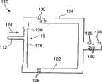
Referring now to fig. 8, asystem 110 for further dispersing the dispersed phase is schematically illustrated. In thesystem 110, aninlet passage 112 delivers fluid flowing in the direction ofarrow 114 to a T-junction 116 where thepassage 112 vertically adjoins a back pressure controlpassage comprising segments Channels collection channels outlet channel 126.
Thechannel 112 delivers a dispersed fluid phase formed within the dispersant fluid phase in any convenient manner (e.g., those described herein with reference to fig. 1 and 3) under certain conditions (e.g., dispersed phase size, flow rate, pressure, etc., known to one of ordinary skill in the art) in the direction ofarrow 114 to cause the dispersed phase to break at T-junction 116. It has been determined in accordance with the present invention that the relative flow resistance within eachchannel channel 118 delivering a relativelysmaller droplet 128 andchannel 120 delivering a relatively larger droplet 130). These droplets are combined in thedelivery channel 126. In an otherwise symmetrical device, the relative lengths of thecounter-flow pressure channels
When using the geometry of the T-junction, the formation of small droplets generally requires a high shear rate in the continuous phase, and thus small droplets tend to correlate with a small volume fraction of the dispersed phase. On the other hand, at lower shear rates, the dispersed phase forms a more elongated shape, which in itself means a high dispersed phase volume fraction.
The function and advantages of these and other embodiments of the present invention will be more fully understood from the following examples. The following examples are intended to illustrate the advantages of the present invention, but are not intended to be illustrative of the full scope of the invention.
Examples
The following example illustrates the formation of droplets of a subject fluid in a continuous phase of an immiscible second dispersed fluid using micro fluidic channel geometry. For the experiments described herein, flow-focus-like geometries have been fabricated in planar microchannel designs using soft lithographic processing methods; i.e., this embodiment demonstrates the ability to rapidly produce a complete microchannel prototype in essentially a single step. The first set of examples uses oil and water as the two immiscible fluids. With oil as the continuous phase liquid (the dispersing fluid) and water as the dispersed phase (the subject fluid), a wide variety of droplet formation patterns (discrete segments) are achieved, depending on the flow rate applied to each inlet stream. The change in the dimensions of the resulting discontinuous section is taken as the oil flow rate QoilThe ratio of the flow rate of the oil to the flow rate of the water, R ═ Qoil/QwaterIs determined. The observed droplets differ thirty times in diameter, with the smallest droplets in the range of hundreds of nanometers.
Fig. 9 is a photographic print (1 ox) of an enlarged photograph of the device schematically illustrated in fig. 3 and 4 made in accordance with the present invention. Water flows as the subject fluid through thesubject fluid channel 34, while oil flows downstream as an immiscible dispersed fluid in the interconnected segments surrounding the subject fluid channel. The two liquid phases are then forced to flow through a dimensionally restrictedregion 40 located downstream of and in line with the outlet of the subject fluid passage in the form of an orifice. The dispersing fluid (oil) exerts pressure and viscous stress, forcing the subject fluid into a narrow filament that then disintegrates inside or just downstream of the dimensionally-restricted section. The Span80 surfactant was dissolved in the oil phase to maintain stability of the microdroplets against coalescence. Fig. 10-12 are photocopies of magnified photographs (magnification 20 x) ofdiscontinuous sections 62 formed insubject fluid 66 in the device by action of dispersingfluid 68 in contact withsubject fluid 66 and forced through dimensionally-restrictedareas 40. As can be seen, a wide range of sizes for thediscontinuity 62 can be provided. For example, in FIG. 11(e), for purposes of this discussion,discontinuities 62, which are designated specifically as 70 and 72, indicate a ratio of the maximum cross-sectional dimensions of each discontinuity of approximately 5: 1.
The microfluidic device shown in fig. 9 (and fig. 10-13) was fabricated from PDMS using the soft lithography technique described by Duffy et al, see the previous references. Nominally, the maximum channel width 50 (see schematic fig. 3) of the interconnect region is 1 millimeter, while the width of thesubject fluid channel 34 is 200 microns. Distance H fromoutlet 36 of subject fluid passageway to restrictedsize area 40focusIs 200 microns and the diameter of the size-restricted portion was 50 microns and 100 microns in two different experiments. The thickness of the inner walls of the device is suitable to maintain 100 microns of the PDMS making the channel walls and the glasstop channel walls 38. The depth of the channel (height ofchannel walls 29 and 31) is 100 microns. The actual dimensions slightly changed in use, as the silicone oil caused the PDMS to swell. These values were determined microscopically.
The fluids used were distilled water (subject fluid) and silicone oil (dispersion fluid; silicone oil AS, Fluka). The viscosity of the silicone oil reported by the manufacturer is 6 mPasec. The silicone oil contained 0.67 wt% Span80 surfactant (Sorbitan mooleate, Aldrich). The surfactant solution was prepared by mechanically mixing the surfactant and silicone oil for about 30 minutes, followed by filtration to eliminate the particulate material and prevent clogging of the microchannels.
The fluids were introduced into the microchannel through a hose (a Clay Adams intramedia PE60 polyethylene tube) and the flow rates were controlled using separate syringe pumps for each fluid (Braintrem scientific BS8000 syringe pump). In this embodiment for verifying the invention, the flow rate Q of the dispersing fluid (oil)oAlways greater than the flow rate Q of the subject fluid (water)i. Three different flow rate ratios are selected, Qo/Q i4, 40 and400, a given oil flow rate corresponds to the total flow rate in both oil inlet flows. For each Qo/QiIn terms of oil flow rates spanning more than two orders of magnitude (4.2X 10) are selected-5ml/sec≤Qo≤8.3×10-3ml/sec). At QoAnd QiEach value of (A) inside the well and droplet formation just downstream of the well was observed using a flip-chip microscope (Model DM IRB, Leica Microsystems) and a high speed camera (Phantom V5.0, Photo-sonic, Inc.; up to 6000 frames/sec). Image processing is used to measure droplet size as reported by equivalent sphere diameter.
Figure 10 (images a-e) is a photographic print of a 20 x magnified photograph of the device of figure 9 in use. Experimental images of the droplet break up sequence occurring inside the size-restricted zone (orifice) are shown. Droplets of consistent size were formed, no satellites were visible, and breakup occurred inside the pores. The time interval between images is 1000 microseconds. Qo=8.3×10⁻⁵ml/sec and Qo/Qi=4。
Fig. 11 (images a-e) are photocopies of 20 x magnified photographs of the device of fig. 9 in use under different conditions. Small satellites (discontinuous areas) accompany each large droplet (discontinuous area); the crushing occurs at two corresponding locations inside the small hole. The time interval between images is 166 microseconds; qo=4.2×10⁻⁴ml/sec, and QO/Qi=40。
FIG. 12 is a photographic print of an enlarged photograph of the arrangement of FIG. 9 in use at various fluid flow rates and flow rate ratios. Each image exhibits discrete areas (droplets) of size and within a specified Qo(lines) and Qo/Qi(column) pattern formed under numerical value. The magnification was 20 ×.
Figure 13 provides a series of photomicrographs showing the formation of bubbles in a liquid. The gas dispersion was made using a microfluidic focusing device similar to that illustrated in figure 3. The subject fluid is nitrogen and the dispersing fluid is water. The subject fluidic channel had a width of 200 microns, while the two dispersive fluidic channels each had a width of 250 microns. The compressed region was an annular aperture having a width of 30 microns. The width of the outlet channel is 750 microns. The pressure of nitrogen fed to the subject fluid channel was 4 psi. The flow rate of the aqueous dispersion was varied stepwise from 4 ml/h down to 0.01 ml/h. As shown in fig. 13(a), at a high dispersion fluid flow rate (4 ml/hr), the volume fraction of gas in the outgoing fluid is small and the bubbles are irregular. When the flow rate of the dispersing fluid was reduced to 1.8 ml/h (fig. 13(b)), clear foam was visible but still not regular enough. When the flow rate of the dispersing fluid was reduced to 0.7 ml/hr (fig. 13(c)), a larger volume fraction of nitrogen and an increased degree of order were seen. This trend continues at flow rates of 0.5 and 0.1 ml/hr, respectively, fig. 13(d) and (e). At lower flow rates, the dispersed fluid portions (nitrogen) will begin to lose their circular shape as shown in fig. 13(f) - (i). It is believed that the dispersion will form a foam when the bubbles begin to assume a non-circular polygonal shape as shown in fig. 13(h) and (i). We believe that these non-circular shapes tend to occur once the volume fraction of gas in the dispersion becomes greater than about 90%. These micrographs demonstrate the ability of the present invention to form ordered phases in liquids at high volume fractions.
Another device was made in order to further disperse the individual fluid portions forming the dispersion in the immiscible fluids. A series of microchannels have been fabricated using Polydimethylsiloxane (PDMS) using known soft lithographic fabrication techniques (see, for example, the article published by Xia et al 1998, incorporated by reference, on angelw.chem., int.edmund.engl., vol.37, p.550; previously cited WO 96/29629). For each of the embodiments described herein, initial droplet formation occurs at the T-junction, and the flow rate is selected to maintain a nearly uniform droplet size. The channel height is 30 microns and at the T-junction where the droplet is first formed, the channel width is also 30 microns. In the case of the use of obstacles to assist in fragmentation, the obstacles had asquare cross-section 60 microns wide and the channel width varied from 120 microns to 240 microns depending on the arrangement of the obstacles within the channel (relative proportions of (a) and (b) shown in fig. 7). Distilled water was chosen to form the dispersed phase, and hexadecane (shear viscosity equal to 0.08g/cm. sec) was used as the continuous phase. 2.0 wt% Span80 surfactant was added to the oil phase to aid droplet formation. The flow rates of the two phases were controlled using separate syringe pumps.
Figure 14(a) shows a row of droplets of a size comparable to the channel flowing past the obstacle placed in the centre of the channel. The droplets deform as they flow in the gap around the obstacle and break up into further dispersed droplets just downstream of the obstacle. Fig. 14(b) and (c) illustrate that changing the asymmetric position of the obstacles allows control of the relative size of the droplets that are further dispersed. In addition to this, a change in the packing configuration of the dispersed droplets may occur downstream of the obstacle. Figure 14(d) illustrates that when the bilayer structure of droplets encounters an obstacle placed off-centre, the device may be arranged such that the droplets in only one layer are further dispersed, thus resulting in a regular sequence of three different sized droplets. Please note that: in order for this passive droplet break-up path to occur, the volume fraction of the dispersed phase should be so large that the droplets have to deform around the obstacle instead of just passing through a narrow gap.
In each of fig. 14(a-d), the obstacles are squares of 60 micron cross-section. In (a), the barrier is placed in the center of the channel such that the ratio (a): (b) is 1: 1. In (b), the channel width is 150 microns and the ratio (a): (b) is 1: 2. In (c), the channel width is 240 microns and the ratio (a): (b) is 1: 5. In (d), every other droplet is further dispersed when the bilayer pattern encounters an off-center obstacle.
Fig. 15 illustrates further dispersion of the dispersed system by subjecting it to epitaxial flow in the vicinity of the T-junction. For flow rates below the threshold, individual droplets do not break up, but flow into channels on each side. For any given ratio of channel width to droplet diameter, there is a critical flow rate above which the droplets break up, as shown in figure 15(a), each droplet breaking up into two further dispersed droplets of equal size. The relative size of the further dispersed droplets may be controlled by the flow resistance of the side channels, which are themselves a function of their length and cross-section. FIGS. 15(b) and (c) show designs in which the side channels have a length ratio that deviates incrementally from 1: 1. In the case of laminar flow channels, the flow resistance is proportional to the channel length. Because the flow resistance sets the relative volumetric flow rate and side channels, the droplet volume also varies with the length ratio. Not only can the flow resistance be controlled by the relative lengths of the flow passages, but pressure actuated valves can also be used.
Figure 16 shows the subsequent application of a large segment of the dispersed phase broken up by the geometrically centered T-junction into further dispersed smaller droplets of comparable size to the channel cross-section. Specifically, at the single inlet (top of section (a)), a large amount of the dispersed phase is provided within the dispersant. The ratio of dispersed phase to dispersant is large, at least 4: 1. At the first T-junction, the dispersed phase is broken up into segments of approximately half the volume of those delivered through the original inlet. Each outlet of the first T-junction acts as an inlet to another T-junction, and through more than two T-junctions, the eight outlets that are ultimately obtained are again combined into a single collection or product channel that contains the highly dispersed droplets within the dispersion (fig. 16 (b)).
Those skilled in the art will recognize that additional components not shown or described herein are useful in implementing the present invention. For example, various different fluid sources, devices for controlling the pressure and/or flow rate of these fluids delivered to the channels presented herein, and the like. Those skilled in the art will readily envision a variety of other means and structures for performing the functions and/or obtaining the results or advantages described herein, and each of such variations or modifications is deemed to be within the scope of the present invention. More generally, those skilled in the art will appreciate that all parameters, dimensions, materials, and configurations described herein are exemplary and that the actual parameters, dimensions, materials, and configurations will depend upon the specific application for which the teachings of the present invention are used. Those skilled in the art will recognize, or be able to ascertain using no more than routine experimentation, many equivalents to the specific embodiments of the invention described herein. It is, therefore, to be understood that the foregoing embodiments are presented by way of example only and that, within the scope of the appended claims and equivalents thereto, the invention may be practiced otherwise than as specifically described herein. The present invention is directed to each individual feature, system, material and/or method described herein. In addition, any combination of two or more such features, systems, materials and/or methods, if such features, systems, materials and/or methods are not mutually inconsistent, is included within the scope of the present invention.
In the claims (and in the specification above), all transitional phrases such as "consisting," "including," "carrying," "having," "containing," "involving," "consisting of," "made of," "formed of," and the like are to be understood to be open-ended, i.e., to mean including but not limited to. Only the transitional phrases "consisting of" and "consisting essentially of" should be defined or semi-defined, respectively, as set forth in the United states Patent Office Manual of Patent application Procedures, section 2111.03 (section 2111.03).
Claims (56)
Translated fromChineseApplications Claiming Priority (5)
| Application Number | Priority Date | Filing Date | Title |
|---|---|---|---|
| US39219502P | 2002-06-28 | 2002-06-28 | |
| US60/392,195 | 2002-06-28 | ||
| US42404202P | 2002-11-05 | 2002-11-05 | |
| US60/424,042 | 2002-11-05 | ||
| PCT/US2003/020542WO2004002627A2 (en) | 2002-06-28 | 2003-06-30 | Method and apparatus for fluid dispersion |
Related Child Applications (1)
| Application Number | Title | Priority Date | Filing Date |
|---|---|---|---|
| CN2010105999339ADivisionCN102059162A (en) | 2002-06-28 | 2003-06-30 | Microfluidic device |
Publications (2)
| Publication Number | Publication Date |
|---|---|
| CN1678397A CN1678397A (en) | 2005-10-05 |
| CN1678397Btrue CN1678397B (en) | 2011-02-09 |
Family
ID=30003231
Family Applications (2)
| Application Number | Title | Priority Date | Filing Date |
|---|---|---|---|
| CN03820494.0AExpired - LifetimeCN1678397B (en) | 2002-06-28 | 2003-06-30 | Method and device for fluid dispersion |
| CN2010105999339APendingCN102059162A (en) | 2002-06-28 | 2003-06-30 | Microfluidic device |
Family Applications After (1)
| Application Number | Title | Priority Date | Filing Date |
|---|---|---|---|
| CN2010105999339APendingCN102059162A (en) | 2002-06-28 | 2003-06-30 | Microfluidic device |
Country Status (7)
| Country | Link |
|---|---|
| US (3) | US7708949B2 (en) |
| EP (2) | EP1515803A2 (en) |
| JP (2) | JP2006507921A (en) |
| CN (2) | CN1678397B (en) |
| AU (1) | AU2003253751B2 (en) |
| CA (1) | CA2491564C (en) |
| WO (1) | WO2004002627A2 (en) |
Families Citing this family (468)
| Publication number | Priority date | Publication date | Assignee | Title |
|---|---|---|---|---|
| JP2006507921A (en) | 2002-06-28 | 2006-03-09 | プレジデント・アンド・フェロウズ・オブ・ハーバード・カレッジ | Method and apparatus for fluid dispersion |
| WO2004071638A2 (en) | 2003-02-11 | 2004-08-26 | Regents Of The University Of California, The | Microfluidic devices and method for controlled viscous shearing and formation of amphiphilic vesicles |
| US20100022414A1 (en) | 2008-07-18 | 2010-01-28 | Raindance Technologies, Inc. | Droplet Libraries |
| GB0307403D0 (en) | 2003-03-31 | 2003-05-07 | Medical Res Council | Selection by compartmentalised screening |
| GB0307428D0 (en) | 2003-03-31 | 2003-05-07 | Medical Res Council | Compartmentalised combinatorial chemistry |
| US20060078893A1 (en) | 2004-10-12 | 2006-04-13 | Medical Research Council | Compartmentalised combinatorial chemistry by microfluidic control |
| WO2004091763A2 (en) | 2003-04-10 | 2004-10-28 | President And Fellows Of Harvard College | Formation and control of fluidic species |
| BRPI0414004A (en) | 2003-08-27 | 2006-10-24 | Harvard College | electronic control of fluidic species |
| US20050221339A1 (en) | 2004-03-31 | 2005-10-06 | Medical Research Council Harvard University | Compartmentalised screening by microfluidic control |
| EP1742979A4 (en)* | 2004-04-23 | 2008-05-21 | Eugenia Kumacheva | Method of producing polymeric particles with selected size, shape, morphology and composition |
| NL1026261C2 (en) | 2004-05-25 | 2005-11-28 | Nanomi B V | Spraying device with a nozzle plate provided with structures for promoting self-breakup, a nozzle plate, and methods for manufacturing and using such a nozzle plate. |
| GB0502398D0 (en)* | 2005-02-04 | 2005-03-16 | Q Chip Ltd | Device and method for producing spherical segmented flow |
| US7655470B2 (en) | 2004-10-29 | 2010-02-02 | University Of Chicago | Method for manipulating a plurality of plugs and performing reactions therein in microfluidic systems |
| US9477233B2 (en) | 2004-07-02 | 2016-10-25 | The University Of Chicago | Microfluidic system with a plurality of sequential T-junctions for performing reactions in microdroplets |
| US7968287B2 (en) | 2004-10-08 | 2011-06-28 | Medical Research Council Harvard University | In vitro evolution in microfluidic systems |
| EP1839760A1 (en)* | 2005-01-17 | 2007-10-03 | Universidad de Sevilla | Method and device for the micromixing of fluids using a reflux cell |
| WO2006078841A1 (en)* | 2005-01-21 | 2006-07-27 | President And Fellows Of Harvard College | Systems and methods for forming fluidic droplets encapsulated in particles such as colloidal particles |
| KR101198038B1 (en) | 2005-01-28 | 2012-11-06 | 듀크 유니버서티 | Apparatuses and methods for manipulating droplets on a printed circuit board |
| US9039273B2 (en) | 2005-03-04 | 2015-05-26 | President And Fellows Of Harvard College | Method and apparatus for forming multiple emulsions |
| US20070054119A1 (en)* | 2005-03-04 | 2007-03-08 | Piotr Garstecki | Systems and methods of forming particles |
| JP2006289250A (en)* | 2005-04-08 | 2006-10-26 | Kao Corp | Micromixer and fluid mixing method using the same |
| US20060280029A1 (en)* | 2005-06-13 | 2006-12-14 | President And Fellows Of Harvard College | Microfluidic mixer |
| US20070141593A1 (en)* | 2005-08-22 | 2007-06-21 | Lee Linda G | Apparatus, system, and method using immiscible-fluid-discrete-volumes |
| US7709544B2 (en)* | 2005-10-25 | 2010-05-04 | Massachusetts Institute Of Technology | Microstructure synthesis by flow lithography and polymerization |
| JP4954216B2 (en)* | 2005-10-25 | 2012-06-13 | マサチューセッツ インスティテュート オブ テクノロジー | Synthesis method of polymer microstructures by flow lithography and polymerization |
| GB2433448B (en) | 2005-12-20 | 2011-03-02 | Q Chip Ltd | Method for the control of chemical processes |
| US20100137163A1 (en) | 2006-01-11 | 2010-06-03 | Link Darren R | Microfluidic Devices and Methods of Use in The Formation and Control of Nanoreactors |
| JP4713397B2 (en) | 2006-01-18 | 2011-06-29 | 株式会社リコー | Microchannel structure and microdroplet generation system |
| WO2007089541A2 (en)* | 2006-01-27 | 2007-08-09 | President And Fellows Of Harvard College | Fluidic droplet coalescence |
| WO2007102785A1 (en)* | 2006-03-09 | 2007-09-13 | Agency For Science, Technology And Research | Apparatus for performing a reaction in a droplet and method of using the same |
| EP2007435B1 (en)* | 2006-03-31 | 2019-12-18 | Massachusetts Institute Of Technology | System for targeted delivery of therapeutic agents |
| US20140193807A1 (en) | 2006-04-18 | 2014-07-10 | Advanced Liquid Logic, Inc. | Bead manipulation techniques |
| US9476856B2 (en) | 2006-04-13 | 2016-10-25 | Advanced Liquid Logic, Inc. | Droplet-based affinity assays |
| US7901947B2 (en) | 2006-04-18 | 2011-03-08 | Advanced Liquid Logic, Inc. | Droplet-based particle sorting |
| US7439014B2 (en) | 2006-04-18 | 2008-10-21 | Advanced Liquid Logic, Inc. | Droplet-based surface modification and washing |
| US10078078B2 (en) | 2006-04-18 | 2018-09-18 | Advanced Liquid Logic, Inc. | Bead incubation and washing on a droplet actuator |
| US8637324B2 (en) | 2006-04-18 | 2014-01-28 | Advanced Liquid Logic, Inc. | Bead incubation and washing on a droplet actuator |
| US8980198B2 (en)* | 2006-04-18 | 2015-03-17 | Advanced Liquid Logic, Inc. | Filler fluids for droplet operations |
| US8809068B2 (en) | 2006-04-18 | 2014-08-19 | Advanced Liquid Logic, Inc. | Manipulation of beads in droplets and methods for manipulating droplets |
| WO2007133590A2 (en)* | 2006-05-08 | 2007-11-22 | Auburn University | Systems for and methods of characterizing reactions |
| WO2009111769A2 (en) | 2008-03-07 | 2009-09-11 | Advanced Liquid Logic, Inc. | Reagent and sample preparation and loading on a fluidic device |
| US9562837B2 (en) | 2006-05-11 | 2017-02-07 | Raindance Technologies, Inc. | Systems for handling microfludic droplets |
| ATE540750T1 (en) | 2006-05-11 | 2012-01-15 | Raindance Technologies Inc | MICROFLUIDIC DEVICE AND METHOD |
| KR100848559B1 (en)* | 2006-06-29 | 2008-07-25 | 엘지디스플레이 주식회사 | Soft Mold Manufacturing Method and Pattern Forming Method Using the Same |
| WO2008017031A2 (en)* | 2006-08-02 | 2008-02-07 | The Regents Of The University Of California | Microfluidic production of monodispersed submicron emulsion through filtration and sorting of satellite drops |
| EP3536396B1 (en) | 2006-08-07 | 2022-03-30 | The President and Fellows of Harvard College | Fluorocarbon emulsion stabilizing surfactants |
| WO2008027558A2 (en) | 2006-08-31 | 2008-03-06 | Codon Devices, Inc. | Iterative nucleic acid assembly using activation of vector-encoded traits |
| KR101556798B1 (en) | 2006-10-05 | 2015-10-01 | 메사츄세츠 인스티튜트 어브 테크놀로지 | Multifunctional Encoded Particles for High-Throughput Analysis |
| US9874501B2 (en) | 2006-11-24 | 2018-01-23 | Curiox Biosystems Pte Ltd. | Use of chemically patterned substrate for liquid handling, chemical and biological reactions |
| WO2008063135A1 (en) | 2006-11-24 | 2008-05-29 | Agency For Science, Technology And Research | Apparatus for processing a sample in a liquid droplet and method of using the same |
| WO2008097559A2 (en) | 2007-02-06 | 2008-08-14 | Brandeis University | Manipulation of fluids and reactions in microfluidic systems |
| AU2008212808B2 (en) | 2007-02-09 | 2013-09-12 | Advanced Liquid Logic, Inc. | Droplet actuator devices and methods employing magnetic beads |
| WO2008109176A2 (en) | 2007-03-07 | 2008-09-12 | President And Fellows Of Harvard College | Assays and other reactions involving droplets |
| WO2008121342A2 (en) | 2007-03-28 | 2008-10-09 | President And Fellows Of Harvard College | Emulsions and techniques for formation |
| WO2008130623A1 (en) | 2007-04-19 | 2008-10-30 | Brandeis University | Manipulation of fluids, fluid components and reactions in microfluidic systems |
| US8691164B2 (en)* | 2007-04-20 | 2014-04-08 | Celula, Inc. | Cell sorting system and methods |
| US8476382B2 (en) | 2007-06-05 | 2013-07-02 | Eugenia Kumacheva | Multiple continuous microfluidic reactors for the scaled up synthesis of gel or polymer particles |
| US20100255556A1 (en)* | 2007-06-29 | 2010-10-07 | President And Fellows Of Harvard College | Methods and apparatus for manipulation of fluidic species |
| GB0712861D0 (en)* | 2007-07-03 | 2007-08-08 | Eastman Kodak Co | Continuous ink jet printing of encapsulated droplets |
| GB0712863D0 (en) | 2007-07-03 | 2007-08-08 | Eastman Kodak Co | Monodisperse droplet generation |
| US20090068170A1 (en)* | 2007-07-13 | 2009-03-12 | President And Fellows Of Harvard College | Droplet-based selection |
| EP2183408A2 (en)* | 2007-08-07 | 2010-05-12 | President And Fellows Of Harvard College | Metal oxide coating on surfaces |
| EP2178641B1 (en)* | 2007-08-09 | 2018-04-11 | Progenity, Inc. | Methods and devices for correlated, multi-parameter single cell measurements and recovery of remnant biological material |
| US8702938B2 (en) | 2007-09-04 | 2014-04-22 | Advanced Liquid Logic, Inc. | Droplet actuator with improved top substrate |
| JP5023902B2 (en)* | 2007-09-06 | 2012-09-12 | 株式会社日立プラントテクノロジー | Emulsifying device |
| US8685323B2 (en)* | 2007-09-19 | 2014-04-01 | Massachusetts Institute Of Technology | Virus/nanowire encapsulation within polymer microgels for 2D and 3D devices for energy and electronics |
| WO2009037680A2 (en) | 2007-09-20 | 2009-03-26 | Jean-Louis Viovy | Encapsulation microfluidic device |
| US8408892B2 (en)* | 2007-10-05 | 2013-04-02 | Snu R&Db Foundation | Fluidic channel system and method for fabricating fine structure |
| US20090098168A1 (en)* | 2007-10-08 | 2009-04-16 | The Regents Of The University Of California | Multiple-layer microbubble liposphere drug delivery vehicle and system |
| US10725020B2 (en) | 2007-11-14 | 2020-07-28 | Curiox Biosystems Pte Ltd. | High throughput miniaturized assay system and methods |
| WO2013114217A1 (en) | 2012-02-05 | 2013-08-08 | Curiox Biosystems Pte Ltd. | Array plates and methods for making and using same |
| EP2235210B1 (en) | 2007-12-21 | 2015-03-25 | President and Fellows of Harvard College | Methods for nucleic acid sequencing |
| CN101945767B (en) | 2007-12-23 | 2013-10-30 | 先进液体逻辑公司 | Droplet actuator configuration and method for directing droplet manipulation |
| EP2271581A4 (en)* | 2008-03-28 | 2014-09-03 | Harvard College | SURFACES COMPRISING MICROFLUIDIC CHANNELS AND HAVING CONTROLLED OILING PROPERTIES |
| WO2009137415A2 (en) | 2008-05-03 | 2009-11-12 | Advanced Liquid Logic, Inc. | Reagent and sample preparation, loading, and storage |
| CN105344389B (en)* | 2008-05-16 | 2018-01-02 | 哈佛大学 | Microfluid system, method and apparatus |
| JP4572973B2 (en)* | 2008-06-16 | 2010-11-04 | ソニー株式会社 | Microchip and flow-feeding method in microchip |
| CN102439165A (en)* | 2008-06-27 | 2012-05-02 | 麻省理工学院 | Microfluidic droplets for metabolic engineering and other applications |
| US12038438B2 (en) | 2008-07-18 | 2024-07-16 | Bio-Rad Laboratories, Inc. | Enzyme quantification |
| JP2010038866A (en)* | 2008-08-08 | 2010-02-18 | Sony Corp | Microchip, particulate dispensing device, and feed flow method |
| DE102008039117B3 (en)* | 2008-08-21 | 2010-05-20 | Institut für Bioprozess- und Analysenmesstechnik e.V. | Arrangement and method for generating, manipulating and analyzing compartments |
| US20110218123A1 (en) | 2008-09-19 | 2011-09-08 | President And Fellows Of Harvard College | Creation of libraries of droplets and related species |
| US11130128B2 (en) | 2008-09-23 | 2021-09-28 | Bio-Rad Laboratories, Inc. | Detection method for a target nucleic acid |
| US12090480B2 (en) | 2008-09-23 | 2024-09-17 | Bio-Rad Laboratories, Inc. | Partition-based method of analysis |
| GB2477053B (en) | 2008-09-23 | 2013-11-13 | Quantalife Inc | Droplet-based assay system |
| US9417190B2 (en) | 2008-09-23 | 2016-08-16 | Bio-Rad Laboratories, Inc. | Calibrations and controls for droplet-based assays |
| US9132394B2 (en) | 2008-09-23 | 2015-09-15 | Bio-Rad Laboratories, Inc. | System for detection of spaced droplets |
| US8633015B2 (en) | 2008-09-23 | 2014-01-21 | Bio-Rad Laboratories, Inc. | Flow-based thermocycling system with thermoelectric cooler |
| US9492797B2 (en) | 2008-09-23 | 2016-11-15 | Bio-Rad Laboratories, Inc. | System for detection of spaced droplets |
| US9764322B2 (en) | 2008-09-23 | 2017-09-19 | Bio-Rad Laboratories, Inc. | System for generating droplets with pressure monitoring |
| US9156010B2 (en) | 2008-09-23 | 2015-10-13 | Bio-Rad Laboratories, Inc. | Droplet-based assay system |
| US8951939B2 (en) | 2011-07-12 | 2015-02-10 | Bio-Rad Laboratories, Inc. | Digital assays with multiplexed detection of two or more targets in the same optical channel |
| US12162008B2 (en) | 2008-09-23 | 2024-12-10 | Bio-Rad Laboratories, Inc. | Partition-based method of analysis |
| US8709762B2 (en) | 2010-03-02 | 2014-04-29 | Bio-Rad Laboratories, Inc. | System for hot-start amplification via a multiple emulsion |
| US8663920B2 (en) | 2011-07-29 | 2014-03-04 | Bio-Rad Laboratories, Inc. | Library characterization by digital assay |
| US10512910B2 (en) | 2008-09-23 | 2019-12-24 | Bio-Rad Laboratories, Inc. | Droplet-based analysis method |
| US8748094B2 (en) | 2008-12-19 | 2014-06-10 | President And Fellows Of Harvard College | Particle-assisted nucleic acid sequencing |
| BRPI1008965B1 (en)* | 2009-03-13 | 2018-12-18 | Harvard College | method for scaling up microfluidic devices and system for droplet formation in parallel microfluidic channels |
| WO2010104604A1 (en) | 2009-03-13 | 2010-09-16 | President And Fellows Of Harvard College | Method for the controlled creation of emulsions, including multiple emulsions |
| EP3415235A1 (en) | 2009-03-23 | 2018-12-19 | Raindance Technologies Inc. | Manipulation of microfluidic droplets |
| CN104722342B (en) | 2009-03-24 | 2017-01-11 | 芝加哥大学 | Slip chip device and method |
| US9464319B2 (en) | 2009-03-24 | 2016-10-11 | California Institute Of Technology | Multivolume devices, kits and related methods for quantification of nucleic acids and other analytes |
| US9447461B2 (en) | 2009-03-24 | 2016-09-20 | California Institute Of Technology | Analysis devices, kits, and related methods for digital quantification of nucleic acids and other analytes |
| US10196700B2 (en) | 2009-03-24 | 2019-02-05 | University Of Chicago | Multivolume devices, kits and related methods for quantification and detection of nucleic acids and other analytes |
| EP2411133B1 (en) | 2009-03-25 | 2013-12-18 | Eastman Kodak Company | Droplet generator |
| WO2010117458A1 (en) | 2009-04-10 | 2010-10-14 | President And Fellows Of Harvard College | Manipulation of particles in channels |
| US9757698B2 (en) | 2009-06-26 | 2017-09-12 | President And Fellows Of Harvard College | Fluid injection |
| US8926065B2 (en) | 2009-08-14 | 2015-01-06 | Advanced Liquid Logic, Inc. | Droplet actuator devices and methods |
| JP5869482B2 (en) | 2009-09-02 | 2016-02-24 | プレジデント アンド フェローズ オブ ハーバード カレッジ | Multiple emulsions produced using jetting and other techniques |
| JP6155418B2 (en) | 2009-09-02 | 2017-07-05 | バイオ−ラッド・ラボラトリーズ・インコーポレーテッド | System for mixing fluids by combining multiple emulsions |
| US8746285B2 (en)* | 2009-09-04 | 2014-06-10 | Auburn University | Programmable fluidic droplet generation |
| WO2011042564A1 (en) | 2009-10-09 | 2011-04-14 | Universite De Strasbourg | Labelled silica-based nanomaterial with enhanced properties and uses thereof |
| TWI421339B (en)* | 2009-10-16 | 2014-01-01 | Academia Sinica | Method of fabricating three dimensional scaffolds and device thereof |
| US8513014B2 (en) | 2009-10-20 | 2013-08-20 | Academia Sinica | Method for fabricating foam scaffolds to culture cells |
| EP3842150A1 (en) | 2009-10-27 | 2021-06-30 | President and Fellows of Harvard College | Droplet creation techniques |
| US10207240B2 (en) | 2009-11-03 | 2019-02-19 | Gen9, Inc. | Methods and microfluidic devices for the manipulation of droplets in high fidelity polynucleotide assembly |
| CN102712935B (en) | 2009-11-04 | 2017-04-26 | 不列颠哥伦比亚大学 | Nucleic acid-containing lipid particles and related methods |
| US9091649B2 (en) | 2009-11-06 | 2015-07-28 | Advanced Liquid Logic, Inc. | Integrated droplet actuator for gel; electrophoresis and molecular analysis |
| ES2574055T3 (en) | 2009-11-25 | 2016-06-14 | Gen9, Inc. | Methods and apparatus for error reduction in chip-based DNA |
| WO2011066185A1 (en) | 2009-11-25 | 2011-06-03 | Gen9, Inc. | Microfluidic devices and methods for gene synthesis |
| EP2516669B1 (en) | 2009-12-21 | 2016-10-12 | Advanced Liquid Logic, Inc. | Enzyme assays on a droplet actuator |
| EP2517025B1 (en) | 2009-12-23 | 2019-11-27 | Bio-Rad Laboratories, Inc. | Methods for reducing the exchange of molecules between droplets |
| WO2011085075A2 (en) | 2010-01-07 | 2011-07-14 | Gen9, Inc. | Assembly of high fidelity polynucleotides |
| US9366632B2 (en) | 2010-02-12 | 2016-06-14 | Raindance Technologies, Inc. | Digital analyte analysis |
| US10351905B2 (en) | 2010-02-12 | 2019-07-16 | Bio-Rad Laboratories, Inc. | Digital analyte analysis |
| US9399797B2 (en) | 2010-02-12 | 2016-07-26 | Raindance Technologies, Inc. | Digital analyte analysis |
| CA2789425C (en) | 2010-02-12 | 2020-04-28 | Raindance Technologies, Inc. | Digital analyte analysis with polymerase error correction |
| US8399198B2 (en) | 2010-03-02 | 2013-03-19 | Bio-Rad Laboratories, Inc. | Assays with droplets transformed into capsules |
| US8716467B2 (en) | 2010-03-03 | 2014-05-06 | Gen9, Inc. | Methods and devices for nucleic acid synthesis |
| CN102971069A (en) | 2010-03-17 | 2013-03-13 | 哈佛学院院长等 | Melt emulsification |
| EP2556170A4 (en) | 2010-03-25 | 2014-01-01 | Quantalife Inc | Droplet transport system for detection |
| CA2767182C (en) | 2010-03-25 | 2020-03-24 | Bio-Rad Laboratories, Inc. | Droplet generation for droplet-based assays |
| EP2550351A4 (en) | 2010-03-25 | 2014-07-09 | Quantalife Inc | Detection system for droplet-based assays |
| USD869308S1 (en) | 2010-04-29 | 2019-12-10 | Sony Corporation | Micro flow channel chip |
| USD673286S1 (en)* | 2010-04-29 | 2012-12-25 | Sony Corporation | Micro flow channel chip |
| USD673287S1 (en) | 2010-11-24 | 2012-12-25 | Sony Corporation | Micro flow channel chip |
| KR101947801B1 (en) | 2010-06-07 | 2019-02-13 | 파이어플라이 바이오웍스, 인코포레이티드 | Scanning multifunctional particles |
| US9499813B2 (en) | 2010-06-10 | 2016-11-22 | President And Fellows Of Harvard College | Systems and methods for amplification and phage display |
| WO2012011877A2 (en) | 2010-07-23 | 2012-01-26 | Curiox Biosystems Pte Ltd | Apparatus and method for multiple reactions in small volumes |
| JP2012024313A (en)* | 2010-07-23 | 2012-02-09 | Nitto Denko Corp | Device for forming droplets, and method for forming droplets |
| US9695390B2 (en) | 2010-08-23 | 2017-07-04 | President And Fellows Of Harvard College | Acoustic waves in microfluidics |
| EP2622103B2 (en) | 2010-09-30 | 2022-11-16 | Bio-Rad Laboratories, Inc. | Sandwich assays in droplets |
| CA3215088A1 (en) | 2010-11-01 | 2012-05-10 | Bio-Rad Laboratories, Inc. | System for forming emulsions |
| EP4039363A1 (en) | 2010-11-12 | 2022-08-10 | Gen9, Inc. | Protein arrays and methods of using and making the same |
| EP3360963B1 (en) | 2010-11-12 | 2019-11-06 | Gen9, Inc. | Methods and devices for nucleic acids synthesis |
| WO2012087350A2 (en) | 2010-12-21 | 2012-06-28 | President And Fellows Of Harvard College | Spray drying techniques |
| BR112013019880A2 (en)* | 2011-02-07 | 2016-10-11 | Harvard College | systems and methods for splitting droplets |
| WO2012109604A1 (en) | 2011-02-11 | 2012-08-16 | Raindance Technologies, Inc. | Thermocycling device for nucleic acid amplification and methods of use |
| WO2012109600A2 (en) | 2011-02-11 | 2012-08-16 | Raindance Technologies, Inc. | Methods for forming mixed droplets |
| US12097495B2 (en) | 2011-02-18 | 2024-09-24 | Bio-Rad Laboratories, Inc. | Methods and compositions for detecting genetic material |
| EP2675819B1 (en) | 2011-02-18 | 2020-04-08 | Bio-Rad Laboratories, Inc. | Compositions and methods for molecular labeling |
| EP2686449B1 (en) | 2011-03-18 | 2020-11-18 | Bio-Rad Laboratories, Inc. | Multiplexed digital assays with combinatorial use of signals |
| ES2656557T3 (en) | 2011-03-31 | 2018-02-27 | Dana-Farber Cancer Institute, Inc. | Method to enrich single-stranded mutant sequences from a mixture of natural and mutant sequences |
| EP3056573B1 (en) | 2011-03-31 | 2018-09-26 | Bio-Rad Laboratories, Inc. | Managing variation in spectroscopic intensity measurements through the use of a reference component |
| EP3395957B1 (en) | 2011-04-25 | 2020-08-12 | Bio-Rad Laboratories, Inc. | Methods and compositions for nucleic acid analysis |
| WO2012154745A2 (en) | 2011-05-09 | 2012-11-15 | Advanced Liquid Logic, Inc. | Microfluidic feedback using impedance detection |
| WO2012162296A2 (en) | 2011-05-23 | 2012-11-29 | President And Fellows Of Harvard College | Control of emulsions, including multiple emulsions |
| US8841071B2 (en) | 2011-06-02 | 2014-09-23 | Raindance Technologies, Inc. | Sample multiplexing |
| EP2714970B1 (en) | 2011-06-02 | 2017-04-19 | Raindance Technologies, Inc. | Enzyme quantification |
| CN106268389A (en) | 2011-07-06 | 2017-01-04 | 哈佛学院院长等 | Multiple Emulsion and for preparing the technology of multiple Emulsion |
| CA2840949A1 (en) | 2011-07-06 | 2013-01-10 | Advanced Liquid Logic Inc | Reagent storage on a droplet actuator |
| US9513253B2 (en) | 2011-07-11 | 2016-12-06 | Advanced Liquid Logic, Inc. | Droplet actuators and techniques for droplet-based enzymatic assays |
| US8658430B2 (en) | 2011-07-20 | 2014-02-25 | Raindance Technologies, Inc. | Manipulating droplet size |
| WO2013016413A2 (en) | 2011-07-25 | 2013-01-31 | Advanced Liquid Logic Inc | Droplet actuator apparatus and system |
| IL280334B2 (en) | 2011-08-26 | 2023-09-01 | Gen9 Inc | Compositions and methods for high fidelity assembly of nucleic acids |
| EP2750787A2 (en) | 2011-08-30 | 2014-07-09 | President and Fellows of Harvard College | Systems and methods for shell encapsulation |
| EP2760578B1 (en)* | 2011-09-28 | 2020-08-26 | President and Fellows of Harvard College | Systems and methods for droplet production and/or fluidic manipulation |
| CA2853316C (en) | 2011-10-25 | 2018-11-27 | The University Of British Columbia | Limit size lipid nanoparticles and related methods |
| CN102500489A (en)* | 2011-11-06 | 2012-06-20 | 中国科学技术大学 | Spray gun spray nozzle capable of realizing minuteness atomization |
| US10731199B2 (en) | 2011-11-21 | 2020-08-04 | Advanced Liquid Logic, Inc. | Glucose-6-phosphate dehydrogenase assays |
| US8771611B2 (en) | 2011-11-28 | 2014-07-08 | Auburn University | System and methods of log-scale concentration gradients |
| KR20140122751A (en) | 2012-02-08 | 2014-10-20 | 프레지던트 앤드 펠로우즈 오브 하바드 칼리지 | Droplet formation using fluid breakup |
| EP2823303A4 (en) | 2012-02-10 | 2015-09-30 | Raindance Technologies Inc | MOLECULAR DIAGNOSTIC SCREEN TYPE ASSAY |
| EP3309262B1 (en) | 2012-02-24 | 2019-09-25 | Bio-Rad Laboratories, Inc. | Labeling and sample preparation for sequencing |
| EP3305918B1 (en) | 2012-03-05 | 2020-06-03 | President and Fellows of Harvard College | Methods for epigenetic sequencing |
| JP6115930B2 (en)* | 2012-03-12 | 2017-04-19 | 国立研究開発法人産業技術総合研究所 | Multi-stage split channel mixer |
| US10080997B2 (en) | 2012-03-16 | 2018-09-25 | Versitech Limited | System and method for generation of emulsions with low interfacial tension and measuring frequency vibrations in the system |
| US9150853B2 (en) | 2012-03-21 | 2015-10-06 | Gen9, Inc. | Methods for screening proteins using DNA encoded chemical libraries as templates for enzyme catalysis |
| US9782733B2 (en)* | 2012-03-22 | 2017-10-10 | Universiteit Twente | Apparatus and method for mass producing a monodisperse microbubble agent |
| US8939551B2 (en) | 2012-03-28 | 2015-01-27 | Eastman Kodak Company | Digital drop patterning device and method |
| US8936354B2 (en) | 2012-03-28 | 2015-01-20 | Eastman Kodak Company | Digital drop patterning device and method |
| US8602535B2 (en) | 2012-03-28 | 2013-12-10 | Eastman Kodak Company | Digital drop patterning device and method |
| US8936353B2 (en) | 2012-03-28 | 2015-01-20 | Eastman Kodak Company | Digital drop patterning device and method |
| US20150177115A1 (en) | 2012-04-06 | 2015-06-25 | Slingshot Biosciences | Hydrogel particles with tunable optical properties |
| WO2013155531A2 (en) | 2012-04-13 | 2013-10-17 | Bio-Rad Laboratories, Inc. | Sample holder with a well having a wicking promoter |
| WO2013159116A1 (en) | 2012-04-20 | 2013-10-24 | University Of Chicago | Fluidic devices for biospecimen preservation |
| CN104428651B (en) | 2012-04-20 | 2019-01-11 | 达丽斯生物医学公司 | Fluidic devices and systems for sample preparation or autonomous analysis |
| AU2013251701A1 (en) | 2012-04-24 | 2014-10-30 | Gen9, Inc. | Methods for sorting nucleic acids and multiplexed preparative in vitro cloning |
| US9803237B2 (en) | 2012-04-24 | 2017-10-31 | California Institute Of Technology | Slip-induced compartmentalization |
| WO2013163246A2 (en) | 2012-04-25 | 2013-10-31 | President And Fellows Of Harvard College | Polymerization reactions within microfluidic devices |
| EP2844768B1 (en) | 2012-04-30 | 2019-03-13 | Raindance Technologies, Inc. | Digital analyte analysis |
| CA2877823A1 (en) | 2012-06-25 | 2014-01-03 | Gen9, Inc. | Methods for nucleic acid assembly and high throughput sequencing |
| JP6222671B2 (en) | 2012-06-27 | 2017-11-01 | アドバンスト リキッド ロジック インコーポレイテッドAdvanced Liquid Logic, Inc. | Technology and droplet actuator design to reduce bubble formation |
| CA2881783A1 (en) | 2012-08-13 | 2014-02-20 | The Regents Of The University Of California | Methods and systems for detecting biological components |
| US11591637B2 (en) | 2012-08-14 | 2023-02-28 | 10X Genomics, Inc. | Compositions and methods for sample processing |
| CN113528634A (en) | 2012-08-14 | 2021-10-22 | 10X基因组学有限公司 | Microcapsule compositions and methods |
| US9951386B2 (en) | 2014-06-26 | 2018-04-24 | 10X Genomics, Inc. | Methods and systems for processing polynucleotides |
| US10221442B2 (en) | 2012-08-14 | 2019-03-05 | 10X Genomics, Inc. | Compositions and methods for sample processing |
| US10400280B2 (en) | 2012-08-14 | 2019-09-03 | 10X Genomics, Inc. | Methods and systems for processing polynucleotides |
| US9701998B2 (en) | 2012-12-14 | 2017-07-11 | 10X Genomics, Inc. | Methods and systems for processing polynucleotides |
| US10273541B2 (en) | 2012-08-14 | 2019-04-30 | 10X Genomics, Inc. | Methods and systems for processing polynucleotides |
| US10323279B2 (en) | 2012-08-14 | 2019-06-18 | 10X Genomics, Inc. | Methods and systems for processing polynucleotides |
| US10752949B2 (en) | 2012-08-14 | 2020-08-25 | 10X Genomics, Inc. | Methods and systems for processing polynucleotides |
| US9328376B2 (en)* | 2012-09-05 | 2016-05-03 | Bio-Rad Laboratories, Inc. | Systems and methods for stabilizing droplets |
| WO2014043388A1 (en) | 2012-09-12 | 2014-03-20 | Gnubio, Inc. | Integrated microfluidic system, method and kit for performing assays |
| WO2014047236A2 (en) | 2012-09-21 | 2014-03-27 | President And Fellows Of Harvard College | Systems and methods for spray drying in microfluidic and other systems |
| WO2014085801A1 (en) | 2012-11-30 | 2014-06-05 | The Broad Institute, Inc. | Cryo-treatment in a microfluidic device |
| EP2931919B1 (en) | 2012-12-14 | 2019-02-20 | 10X Genomics, Inc. | Methods and systems for processing polynucleotides |
| US10533221B2 (en) | 2012-12-14 | 2020-01-14 | 10X Genomics, Inc. | Methods and systems for processing polynucleotides |
| AU2014214682B2 (en) | 2013-02-08 | 2018-07-26 | 10X Genomics, Inc. | Polynucleotide barcode generation |
| WO2014138154A1 (en)* | 2013-03-06 | 2014-09-12 | President And Fellows Of Harvard College | Devices and methods for forming relatively monodisperse droplets |
| WO2014153071A1 (en) | 2013-03-14 | 2014-09-25 | The Broad Institute, Inc. | Methods for quantitating dna using digital multiple displacement amplification |
| WO2014144495A1 (en) | 2013-03-15 | 2014-09-18 | Abvitro, Inc. | Single cell bar-coding for antibody discovery |
| CA2906732C (en) | 2013-03-15 | 2023-08-08 | The University Of British Columbia | Lipid nanoparticles for transfection and related methods |
| GB201306445D0 (en) | 2013-04-09 | 2013-05-22 | Base4 Innovation Ltd | Single nucleotide detection method |
| GB201306444D0 (en) | 2013-04-09 | 2013-05-22 | Base4 Innovation Ltd | Single nucleotide detection method |
| WO2014172288A2 (en) | 2013-04-19 | 2014-10-23 | Raindance Technologies, Inc. | Digital analyte analysis |
| CN103285946A (en)* | 2013-05-27 | 2013-09-11 | 苏州扬清芯片科技有限公司 | Biochip and control method thereof |
| CN103285947A (en)* | 2013-05-27 | 2013-09-11 | 苏州扬清芯片科技有限公司 | Droplet micro-fluidic chip and operation method thereof |
| KR20140144408A (en)* | 2013-06-11 | 2014-12-19 | 삼성전기주식회사 | Droplet forming device and method for forming droplet using the same |
| WO2014201196A2 (en) | 2013-06-14 | 2014-12-18 | President And Fellows Of Harvard College | Coalescence of droplets |
| US9557318B2 (en) | 2013-07-09 | 2017-01-31 | Curiox Biosystems Pte Ltd. | Array plates for washing samples |
| US10395758B2 (en) | 2013-08-30 | 2019-08-27 | 10X Genomics, Inc. | Sequencing methods |
| US9233859B2 (en) | 2013-09-30 | 2016-01-12 | Uchicago Argonne, Llc. | Microfluidic process monitor for industrial solvent extraction system |
| US11901041B2 (en) | 2013-10-04 | 2024-02-13 | Bio-Rad Laboratories, Inc. | Digital analysis of nucleic acid modification |
| WO2015069634A1 (en) | 2013-11-08 | 2015-05-14 | President And Fellows Of Harvard College | Microparticles, methods for their preparation and use |
| US10801070B2 (en) | 2013-11-25 | 2020-10-13 | The Broad Institute, Inc. | Compositions and methods for diagnosing, evaluating and treating cancer |
| WO2015085147A1 (en) | 2013-12-05 | 2015-06-11 | The Broad Institute Inc. | Polymorphic gene typing and somatic change detection using sequencing data |
| US9944977B2 (en) | 2013-12-12 | 2018-04-17 | Raindance Technologies, Inc. | Distinguishing rare variations in a nucleic acid sequence from a sample |
| US9824068B2 (en) | 2013-12-16 | 2017-11-21 | 10X Genomics, Inc. | Methods and apparatus for sorting data |
| EP3082853A2 (en) | 2013-12-20 | 2016-10-26 | The Broad Institute, Inc. | Combination therapy with neoantigen vaccine |
| EP3090063B1 (en) | 2013-12-31 | 2019-11-06 | Bio-Rad Laboratories, Inc. | Method for detection of latent retrovirus |
| EP3110971B1 (en) | 2014-02-27 | 2019-05-08 | The Broad Institute Inc. | T cell balance gene expression and methods of use thereof |
| EP3117897A4 (en)* | 2014-03-11 | 2017-10-18 | Toppan Printing Co., Ltd. | Droplet producing device, droplet producing method, liposome producing method, fixture, and droplet producing kit |
| CN114534806B (en) | 2014-04-10 | 2024-03-29 | 10X基因组学有限公司 | Fluidic devices, systems and methods for packaging and partitioning reagents and uses thereof |
| WO2015160919A1 (en) | 2014-04-16 | 2015-10-22 | President And Fellows Of Harvard College | Systems and methods for producing droplet emulsions with relatively thin shells |
| US20150298091A1 (en) | 2014-04-21 | 2015-10-22 | President And Fellows Of Harvard College | Systems and methods for barcoding nucleic acids |
| JP6853667B2 (en) | 2014-04-21 | 2021-03-31 | プレジデント アンド フェローズ オブ ハーバード カレッジ | Systems and methods for barcoding nucleic acids |
| CA2948979A1 (en) | 2014-05-14 | 2015-11-19 | University Of Limerick | Microfluidic devices that include channels that are slidable relative to each other and methods of use thereof |
| EP3155086B1 (en) | 2014-06-16 | 2021-10-20 | Bio-Rad Laboratories, Inc. | Size alternating injection into drops to facilitate sorting |
| WO2015200616A1 (en) | 2014-06-26 | 2015-12-30 | President And Fellows Of Harvard College | Fluid injection using acoustic waves |
| US12312640B2 (en) | 2014-06-26 | 2025-05-27 | 10X Genomics, Inc. | Analysis of nucleic acid sequences |
| AU2015279617A1 (en) | 2014-06-26 | 2017-01-12 | 10X Genomics, Inc. | Analysis of nucleic acid sequences |
| KR102755843B1 (en) | 2014-06-26 | 2025-01-15 | 10엑스 제노믹스, 인크. | Methods of analyzing nucleic acids from individual cells or cell populations |
| EP4235677A3 (en) | 2014-06-26 | 2023-11-22 | 10X Genomics, Inc. | Processes and systems for nucleic acid sequence assembly |
| EP3160654A4 (en) | 2014-06-27 | 2017-11-15 | The Regents of The University of California | Pcr-activated sorting (pas) |
| EP3177405B1 (en) | 2014-08-06 | 2020-05-06 | S.C. Johnson & Son, Inc. | Spray inserts |
| CN107873054B (en) | 2014-09-09 | 2022-07-12 | 博德研究所 | Droplet-based method and device for complex single-cell nucleic acid analysis |
| SG11201702060VA (en) | 2014-09-15 | 2017-04-27 | Abvitro Inc | High-throughput nucleotide library sequencing |
| WO2016065056A1 (en) | 2014-10-22 | 2016-04-28 | The Regents Of The University Of California | High definition microdroplet printer |
| CA2964472A1 (en) | 2014-10-29 | 2016-05-06 | 10X Genomics, Inc. | Methods and compositions for targeted nucleic acid sequencing |
| US10000799B2 (en) | 2014-11-04 | 2018-06-19 | Boreal Genomics, Inc. | Methods of sequencing with linked fragments |
| US9975122B2 (en) | 2014-11-05 | 2018-05-22 | 10X Genomics, Inc. | Instrument systems for integrated sample processing |
| JP6742311B2 (en) | 2014-11-14 | 2020-08-19 | アテナ ダイアグナスティクス,インコーポレイテッド | Method for detecting silent carrier genotype |
| WO2016085741A1 (en) | 2014-11-24 | 2016-06-02 | The Procter & Gamble Company | Systems for encapsulation of actives within droplets and other compartments |
| EP3234193B1 (en) | 2014-12-19 | 2020-07-15 | Massachusetts Institute of Technology | Molecular biomarkers for cancer immunotherapy |
| EP3234130B1 (en) | 2014-12-19 | 2020-11-25 | The Broad Institute, Inc. | Methods for profiling the t-cell- receptor repertoire |
| US10221436B2 (en) | 2015-01-12 | 2019-03-05 | 10X Genomics, Inc. | Processes and systems for preparation of nucleic acid sequencing libraries and libraries prepared using same |
| US10650912B2 (en) | 2015-01-13 | 2020-05-12 | 10X Genomics, Inc. | Systems and methods for visualizing structural variation and phasing information |
| NL2014178B1 (en)* | 2015-01-22 | 2017-01-05 | Tide Microfluidics B V | System and method for controlled manufacturing of mono-disperse microbubbles. |
| US10875017B2 (en) | 2015-01-23 | 2020-12-29 | Neofluidics Llc | Microfluidic serial dilution platform based well-plate using an oil-free immiscible phase driven by manual or electronic pipettors |
| US12290811B2 (en) | 2015-01-23 | 2025-05-06 | Unchained Labs | Microfluidic serial dilution platform based well-plate using an oil-free immiscible phase driven by manual or electronic pipettors |
| US20160238506A1 (en)* | 2015-02-02 | 2016-08-18 | Derek Oberreit | Ice nucleii counter technology |
| CN107530654A (en) | 2015-02-04 | 2018-01-02 | 加利福尼亚大学董事会 | Sequence nucleic acids by barcoding in discrete entities |
| US20160358722A1 (en)* | 2015-02-05 | 2016-12-08 | Ramasamy Lakshmanan | Intelligent wireless and wired control of devices |
| CA2975301A1 (en) | 2015-02-09 | 2016-08-18 | Slingshot Biosciences, Inc. | Hydrogel particles with tunable optical properties and methods for using the same |
| US10854315B2 (en) | 2015-02-09 | 2020-12-01 | 10X Genomics, Inc. | Systems and methods for determining structural variation and phasing using variant call data |
| US10697000B2 (en) | 2015-02-24 | 2020-06-30 | 10X Genomics, Inc. | Partition processing methods and systems |
| EP3936619A1 (en) | 2015-02-24 | 2022-01-12 | 10X Genomics, Inc. | Methods for targeted nucleic acid sequence coverage |
| WO2016138488A2 (en) | 2015-02-26 | 2016-09-01 | The Broad Institute Inc. | T cell balance gene expression, compositions of matters and methods of use thereof |
| EP3268462B1 (en) | 2015-03-11 | 2021-08-11 | The Broad Institute, Inc. | Genotype and phenotype coupling |
| US10876156B2 (en) | 2015-03-13 | 2020-12-29 | President And Fellows Of Harvard College | Determination of cells using amplification |
| AU2016248995B2 (en) | 2015-04-17 | 2022-04-28 | President And Fellows Of Harvard College | Barcoding systems and methods for gene sequencing and other applications |
| WO2016187508A2 (en) | 2015-05-20 | 2016-11-24 | The Broad Institute Inc. | Shared neoantigens |
| CN107405633A (en)* | 2015-05-22 | 2017-11-28 | 香港科技大学 | Drop generator for inducing generation of drops based on high aspect ratio |
| US10545139B2 (en) | 2015-06-16 | 2020-01-28 | Curiox Biosystems Pte Ltd. | Methods and devices for performing biological assays using magnetic components |
| WO2016205728A1 (en) | 2015-06-17 | 2016-12-22 | Massachusetts Institute Of Technology | Crispr mediated recording of cellular events |
| WO2016207721A1 (en) | 2015-06-25 | 2016-12-29 | University Of Limerick | Mechanical device for generating combinatorial library |
| WO2017015414A1 (en) | 2015-07-23 | 2017-01-26 | Zito Jr Arthur J | Responsive dispersion from compartment in aqueous solution |
| EP3341508A4 (en) | 2015-08-25 | 2019-05-15 | Bio-Rad Laboratories, Inc. | DIGITAL IMMUNOLOGICAL ASSAY |
| DK3341116T3 (en) | 2015-08-27 | 2022-05-02 | Harvard College | SORTING PROCEDURE USING ACOUSTIC WAVES |
| US10647981B1 (en) | 2015-09-08 | 2020-05-12 | Bio-Rad Laboratories, Inc. | Nucleic acid library generation methods and compositions |
| CA2999888C (en) | 2015-09-24 | 2024-04-09 | Abvitro Llc | Affinity-oligonucleotide conjugates and uses thereof |
| WO2018057051A1 (en) | 2016-09-24 | 2018-03-29 | Abvitro Llc | Affinity-oligonucleotide conjugates and uses thereof |
| EP3353325B1 (en) | 2015-09-24 | 2024-03-20 | AbVitro LLC | Single amplicon activated exclusion pcr |
| CN113774495A (en) | 2015-09-25 | 2021-12-10 | 阿布维特罗有限责任公司 | High throughput method for T cell receptor targeted identification of naturally paired T cell receptor sequences |
| WO2017066231A1 (en) | 2015-10-13 | 2017-04-20 | President And Fellows Of Harvard College | Systems and methods for making and using gel microspheres |
| KR102426825B1 (en) | 2015-10-27 | 2022-07-28 | 버클리 라잇츠, 인크. | Microfluidic Electrowetting Device Apparatus With Covalently Bound Hydrophobic Surfaces |
| US11092607B2 (en) | 2015-10-28 | 2021-08-17 | The Board Institute, Inc. | Multiplex analysis of single cell constituents |
| WO2017075294A1 (en) | 2015-10-28 | 2017-05-04 | The Board Institute Inc. | Assays for massively combinatorial perturbation profiling and cellular circuit reconstruction |
| WO2017075297A1 (en) | 2015-10-28 | 2017-05-04 | The Broad Institute Inc. | High-throughput dynamic reagent delivery system |
| CN105435869B (en)* | 2015-11-06 | 2017-05-10 | 常州工学院 | Device and method for splitting microdroplets in a microchannel |
| US11371094B2 (en) | 2015-11-19 | 2022-06-28 | 10X Genomics, Inc. | Systems and methods for nucleic acid processing using degenerate nucleotides |
| US10522243B2 (en) | 2015-11-20 | 2019-12-31 | Bio-Rad Laboratories, Inc. | Sparse identity spaces in droplet sequencing |
| PT3882357T (en) | 2015-12-04 | 2022-09-05 | 10X Genomics Inc | Methods and compositions for nucleic acid analysis |
| US12071663B2 (en) | 2016-01-15 | 2024-08-27 | Massachusetts Institute Of Technology | Semi-permeable arrays for analyzing biological systems and methods of using same |
| WO2017136751A1 (en) | 2016-02-05 | 2017-08-10 | The Broad Institute Inc. | Multi-stage, multiplexed target isolation and processing from heterogeneous populations |
| EP3414341A4 (en) | 2016-02-11 | 2019-10-09 | 10X Genomics, Inc. | SYSTEMS, METHODS, AND MEDIA FOR ASSEMBLING NOVO OF GENOME SEQUENCE DATA OVERALL |
| EP3420102B1 (en) | 2016-02-22 | 2024-04-03 | Massachusetts Institute of Technology | Methods for identifying and modulating immune phenotypes |
| US11427861B2 (en) | 2016-03-17 | 2022-08-30 | Massachusetts Institute Of Technology | Methods for identifying and modulating co-occurant cellular phenotypes |
| WO2017164936A1 (en) | 2016-03-21 | 2017-09-28 | The Broad Institute, Inc. | Methods for determining spatial and temporal gene expression dynamics in single cells |
| WO2017165791A1 (en) | 2016-03-25 | 2017-09-28 | President And Fellows Of Harvard College | Microfluidic determination of immune and other cells |
| US10961573B2 (en) | 2016-03-28 | 2021-03-30 | Boreal Genomics, Inc. | Linked duplex target capture |
| WO2017168331A1 (en) | 2016-03-28 | 2017-10-05 | Boreal Genomics, Inc. | Linked duplex fragment sequencing |
| CN109311010B (en) | 2016-04-15 | 2022-05-17 | 哈佛学院院长及董事 | Systems and methods for collecting droplets or other entities |
| CN105712319B (en)* | 2016-04-29 | 2018-01-23 | 清华大学 | The preparation facilities of macroscopical aggregation of micro Nano material |
| WO2017192774A1 (en) | 2016-05-03 | 2017-11-09 | Pneuma Respiratory, Inc. | Methods for the systemic delivery of therapeutic agents to the pulmonary system using a droplet delivery device |
| US11285284B2 (en) | 2016-05-03 | 2022-03-29 | Pneuma Respiratory, Inc. | Methods for treatment of pulmonary lung diseases with improved therapeutic efficacy and improved dose efficiency |
| US11285283B2 (en) | 2016-05-03 | 2022-03-29 | Pneuma Respiratory, Inc. | Methods for generating and delivering droplets to the pulmonary system using a droplet delivery device |
| WO2017192782A1 (en) | 2016-05-03 | 2017-11-09 | Pneuma Respiratory, Inc. | Systems and methods comprising a droplet delivery device and a breathing assist device for therapeutic treatment |
| WO2017197343A2 (en) | 2016-05-12 | 2017-11-16 | 10X Genomics, Inc. | Microfluidic on-chip filters |
| WO2017197338A1 (en) | 2016-05-13 | 2017-11-16 | 10X Genomics, Inc. | Microfluidic systems and methods of use |
| CN107414080B (en)* | 2016-05-23 | 2024-04-16 | 中国科学院理化技术研究所 | Liquid metal 3D prints shower nozzle device and is equipped with device's 3D printer |
| EP3686287A1 (en) | 2016-06-28 | 2020-07-29 | Hifibio | Method for transcriptome analysis of single cells |
| US20220008918A1 (en) | 2016-07-08 | 2022-01-13 | California Institute Of Technology | Methods and devices for performing flow-through capture of low-concentration analytes |
| EP3481540B1 (en) | 2016-07-08 | 2022-12-21 | President and Fellows of Harvard College | Formation of colloids or gels within droplets |
| US11142791B2 (en) | 2016-08-10 | 2021-10-12 | The Regents Of The University Of California | Combined multiple-displacement amplification and PCR in an emulsion microdroplet |
| US10654040B2 (en) | 2016-08-18 | 2020-05-19 | Northeastern University | Platform for liquid droplet formation and isolation |
| CA3048420A1 (en) | 2016-12-09 | 2018-06-14 | Boreal Genomics, Inc. | Linked ligation |
| CA3047328A1 (en) | 2016-12-21 | 2018-06-28 | The Regents Of The University Of California | Single cell genomic sequencing using hydrogel based droplets |
| US10011872B1 (en) | 2016-12-22 | 2018-07-03 | 10X Genomics, Inc. | Methods and systems for processing polynucleotides |
| US10550429B2 (en) | 2016-12-22 | 2020-02-04 | 10X Genomics, Inc. | Methods and systems for processing polynucleotides |
| US10815525B2 (en) | 2016-12-22 | 2020-10-27 | 10X Genomics, Inc. | Methods and systems for processing polynucleotides |
| EP3574116A1 (en) | 2017-01-24 | 2019-12-04 | The Broad Institute, Inc. | Compositions and methods for detecting a mutant variant of a polynucleotide |
| US12264411B2 (en) | 2017-01-30 | 2025-04-01 | 10X Genomics, Inc. | Methods and systems for analysis |
| CN117512066A (en) | 2017-01-30 | 2024-02-06 | 10X基因组学有限公司 | Methods and systems for droplet-based single cell barcoding |
| US10995333B2 (en) | 2017-02-06 | 2021-05-04 | 10X Genomics, Inc. | Systems and methods for nucleic acid preparation |
| US12180546B2 (en) | 2017-03-17 | 2024-12-31 | Massachusetts Institute Of Technology | Methods for identifying and modulating co-occurant cellular phenotypes |
| LT3375889T (en) | 2017-03-17 | 2020-06-25 | Hifibio Sas | SINGLE CELL ANALYSIS |
| CN110709979B (en) | 2017-04-05 | 2024-04-09 | 科睿思生物科技(私人)有限公司 | Method, device and apparatus for cleaning samples on an array plate |
| US20210293783A1 (en) | 2017-04-18 | 2021-09-23 | The General Hospital Corporation | Compositions for detecting secretion and methods of use |
| EP3615220A4 (en) | 2017-04-28 | 2020-12-30 | Neofluidics, LLC | Fluidic devices with reaction wells and uses thereof |
| US11072816B2 (en) | 2017-05-03 | 2021-07-27 | The Broad Institute, Inc. | Single-cell proteomic assay using aptamers |
| CN119570912A (en) | 2017-05-15 | 2025-03-07 | 贝斯4创新公司 | Single nucleotide detection methods and related probes |
| US10544413B2 (en) | 2017-05-18 | 2020-01-28 | 10X Genomics, Inc. | Methods and systems for sorting droplets and beads |
| EP4435113A1 (en) | 2017-05-18 | 2024-09-25 | 10x Genomics, Inc. | Methods and systems for sorting droplets and beads |
| CN110799231B (en) | 2017-05-19 | 2022-08-02 | 精呼吸股份有限公司 | Dry powder conveying device and using method thereof |
| WO2018213774A1 (en) | 2017-05-19 | 2018-11-22 | 10X Genomics, Inc. | Systems and methods for analyzing datasets |
| WO2018217831A1 (en) | 2017-05-22 | 2018-11-29 | Arizona Board Of Regents On Behalf Of Arizona State University | Metal electrode based 3d printed device for tuning microfluidic droplet generation frequency and synchronizing phase for serial femtosecond crystallography |
| US10844372B2 (en) | 2017-05-26 | 2020-11-24 | 10X Genomics, Inc. | Single cell analysis of transposase accessible chromatin |
| WO2018218222A1 (en) | 2017-05-26 | 2018-11-29 | Goldfless Stephen Jacob | High-throughput polynucleotide library sequencing and transcriptome analysis |
| CN116064732A (en) | 2017-05-26 | 2023-05-05 | 10X基因组学有限公司 | Single-cell analysis of transposase-accessible chromatin |
| US11745181B2 (en) | 2017-08-09 | 2023-09-05 | Unchained Labs | Devices and methods for bioassay |
| US10610865B2 (en) | 2017-08-22 | 2020-04-07 | 10X Genomics, Inc. | Droplet forming devices and system with differential surface properties |
| EP3679370A1 (en) | 2017-09-07 | 2020-07-15 | Juno Therapeutics, Inc. | Methods of identifying cellular attributes related to outcomes associated with cell therapy |
| US10837047B2 (en) | 2017-10-04 | 2020-11-17 | 10X Genomics, Inc. | Compositions, methods, and systems for bead formation using improved polymers |
| US10590244B2 (en) | 2017-10-04 | 2020-03-17 | 10X Genomics, Inc. | Compositions, methods, and systems for bead formation using improved polymers |
| CN111526914A (en) | 2017-10-04 | 2020-08-11 | 精呼吸股份有限公司 | Electronic respiration actuated linear liquid drop conveying device and using method thereof |
| CA3079189A1 (en) | 2017-10-17 | 2019-04-25 | Pneuma Respiratory, Inc. | Nasal drug delivery apparatus and methods of use |
| US10501739B2 (en) | 2017-10-18 | 2019-12-10 | Mission Bio, Inc. | Method, systems and apparatus for single cell analysis |
| EP3697537A4 (en) | 2017-10-18 | 2021-10-20 | Group K Diagnostics, Inc. | SINGLE LAYER MICROFLUIDIC DEVICE AND METHOD OF MANUFACTURING AND USING THEREOF |
| US11732257B2 (en) | 2017-10-23 | 2023-08-22 | Massachusetts Institute Of Technology | Single cell sequencing libraries of genomic transcript regions of interest in proximity to barcodes, and genotyping of said libraries |
| WO2019084043A1 (en) | 2017-10-26 | 2019-05-02 | 10X Genomics, Inc. | Methods and systems for nuclecic acid preparation and chromatin analysis |
| WO2019083852A1 (en) | 2017-10-26 | 2019-05-02 | 10X Genomics, Inc. | Microfluidic channel networks for partitioning |
| CN114525273B (en) | 2017-10-27 | 2025-01-28 | 10X基因组学有限公司 | Methods and systems for sample preparation and analysis |
| JP2021502178A (en) | 2017-11-08 | 2021-01-28 | ニューマ・リスパイラトリー・インコーポレイテッド | In-line droplet delivery device with a small volume ampoule and electrically actuated by breathing and how to use |
| EP3706905A4 (en) | 2017-11-10 | 2021-11-03 | Neofluidics, LLC | Integrated fluidic circuit and device for droplet manipulation and methods thereof |
| US12221720B2 (en) | 2017-11-13 | 2025-02-11 | The Broad Institute, Inc. | Methods for determining spatial and temporal gene expression dynamics during adult neurogenesis in single cells |
| EP3954782A1 (en) | 2017-11-15 | 2022-02-16 | 10X Genomics, Inc. | Functionalized gel beads |
| US10829815B2 (en) | 2017-11-17 | 2020-11-10 | 10X Genomics, Inc. | Methods and systems for associating physical and genetic properties of biological particles |
| CN107941659B (en)* | 2017-11-20 | 2020-05-19 | 武汉科技大学 | A device for measuring seepage velocity during the freezing process of fissure water |
| WO2019108851A1 (en) | 2017-11-30 | 2019-06-06 | 10X Genomics, Inc. | Systems and methods for nucleic acid preparation and analysis |
| WO2019113506A1 (en) | 2017-12-07 | 2019-06-13 | The Broad Institute, Inc. | Methods and compositions for multiplexing single cell and single nuclei sequencing |
| CN118818037A (en) | 2017-12-12 | 2024-10-22 | 10X基因组学有限公司 | Systems and methods for single cell processing |
| US11173487B2 (en) | 2017-12-19 | 2021-11-16 | Arizona Board Of Regents On Behalf Of Arizona State University | Deterministic ratchet for sub-micrometer bioparticle separation |
| WO2019126789A1 (en) | 2017-12-22 | 2019-06-27 | 10X Genomics, Inc. | Systems and methods for processing nucleic acid molecules from one or more cells |
| CN111787865B (en) | 2017-12-28 | 2024-12-03 | 爱惜康有限责任公司 | Surgical instrument including push button circuit |
| US12408638B2 (en) | 2018-01-19 | 2025-09-09 | Arthur J. Zito, Jr. | Responsive dispersion from compartment in aqueous solution |
| WO2019157529A1 (en) | 2018-02-12 | 2019-08-15 | 10X Genomics, Inc. | Methods characterizing multiple analytes from individual cells or cell populations |
| US11639928B2 (en) | 2018-02-22 | 2023-05-02 | 10X Genomics, Inc. | Methods and systems for characterizing analytes from individual cells or cell populations |
| WO2019169028A1 (en) | 2018-02-28 | 2019-09-06 | 10X Genomics, Inc. | Transcriptome sequencing through random ligation |
| US11841371B2 (en) | 2018-03-13 | 2023-12-12 | The Broad Institute, Inc. | Proteomics and spatial patterning using antenna networks |
| SG11202009889VA (en) | 2018-04-06 | 2020-11-27 | 10X Genomics Inc | Systems and methods for quality control in single cell processing |
| WO2019217758A1 (en) | 2018-05-10 | 2019-11-14 | 10X Genomics, Inc. | Methods and systems for molecular library generation |
| US11414701B2 (en) | 2018-05-24 | 2022-08-16 | The Broad Institute, Inc. | Multimodal readouts for quantifying and sequencing nucleic acids in single cells |
| US11932899B2 (en) | 2018-06-07 | 2024-03-19 | 10X Genomics, Inc. | Methods and systems for characterizing nucleic acid molecules |
| WO2019241488A1 (en)* | 2018-06-14 | 2019-12-19 | Regents Of The University Of Minnesota | Counterflow mixer and atomizer |
| US11703427B2 (en) | 2018-06-25 | 2023-07-18 | 10X Genomics, Inc. | Methods and systems for cell and bead processing |
| US12188014B1 (en) | 2018-07-25 | 2025-01-07 | 10X Genomics, Inc. | Compositions and methods for nucleic acid processing using blocking agents |
| US20200032335A1 (en) | 2018-07-27 | 2020-01-30 | 10X Genomics, Inc. | Systems and methods for metabolome analysis |
| SG11202101164TA (en) | 2018-08-03 | 2021-03-30 | 10X Genomics Inc | Methods and systems to minimize barcode exchange |
| WO2020041148A1 (en) | 2018-08-20 | 2020-02-27 | 10X Genomics, Inc. | Methods and systems for detection of protein-dna interactions using proximity ligation |
| US12065688B2 (en) | 2018-08-20 | 2024-08-20 | 10X Genomics, Inc. | Compositions and methods for cellular processing |
| WO2020039261A1 (en) | 2018-08-23 | 2020-02-27 | Boreal Genomics, Inc. | Linked target capture and ligation |
| AU2019352957A1 (en)* | 2018-10-01 | 2021-04-29 | Pneuma Respiratory, Inc. | Delivery of low surface tension compositions to the pulmonary system via electronic breath actuated droplet delivery device |
| LT6742B (en) | 2018-10-10 | 2020-07-10 | Vilnius University | Catalytic biomolecule activity recording into dna sequence |
| US20220411783A1 (en) | 2018-10-12 | 2022-12-29 | The Broad Institute, Inc. | Method for extracting nuclei or whole cells from formalin-fixed paraffin-embedded tissues |
| GB201817321D0 (en) | 2018-10-24 | 2018-12-05 | Nanna Therapeutics Ltd | Microbeads for tagless encoded chemical library screening |
| CA3158313A1 (en) | 2018-10-26 | 2020-04-30 | Unchained Labs | Fluidic devices with reaction wells and constriction channels and uses thereof |
| USD879999S1 (en) | 2018-11-02 | 2020-03-31 | Group K Diagnostics, Inc. | Microfluidic device |
| US12165743B2 (en) | 2018-11-09 | 2024-12-10 | The Broad Institute, Inc. | Compressed sensing for screening and tissue imaging |
| KR20210104698A (en) | 2018-11-14 | 2021-08-25 | 더 브로드 인스티튜트, 인코퍼레이티드 | Droplet diagnosis system and method based on CRISPR system |
| CA3119971A1 (en) | 2018-11-14 | 2020-05-22 | Pardis SABETI | Multiplexing highly evolving viral variants with sherlock |
| US11459607B1 (en) | 2018-12-10 | 2022-10-04 | 10X Genomics, Inc. | Systems and methods for processing-nucleic acid molecules from a single cell using sequential co-partitioning and composite barcodes |
| WO2020123657A2 (en) | 2018-12-11 | 2020-06-18 | 10X Genomics, Inc. | Methods and devices for detecting and sorting droplets or particles |
| US20250043366A1 (en) | 2018-12-13 | 2025-02-06 | The Broad Institute, Inc. | Tiled assays using crispr-cas based detection |
| US20220062394A1 (en) | 2018-12-17 | 2022-03-03 | The Broad Institute, Inc. | Methods for identifying neoantigens |
| EP3670667A1 (en) | 2018-12-19 | 2020-06-24 | Paris Sciences et Lettres - Quartier Latin | Identification of cognate pairs of ligands and receptors |
| WO2020139844A1 (en) | 2018-12-24 | 2020-07-02 | 10X Genomics, Inc. | Devices, systems, and methods for controlling liquid flow |
| WO2020141464A1 (en) | 2019-01-03 | 2020-07-09 | Boreal Genomics, Inc. | Linked target capture |
| US12169198B2 (en) | 2019-01-08 | 2024-12-17 | 10X Genomics, Inc. | Systems and methods for sample analysis |
| US11845983B1 (en) | 2019-01-09 | 2023-12-19 | 10X Genomics, Inc. | Methods and systems for multiplexing of droplet based assays |
| US20220119871A1 (en) | 2019-01-28 | 2022-04-21 | The Broad Institute, Inc. | In-situ spatial transcriptomics |
| US12305239B2 (en) | 2019-02-12 | 2025-05-20 | 10X Genomics, Inc. | Analysis of nucleic acid sequences |
| WO2020167866A1 (en) | 2019-02-12 | 2020-08-20 | 10X Genomics, Inc. | Systems and methods for transposon loading |
| US11851683B1 (en) | 2019-02-12 | 2023-12-26 | 10X Genomics, Inc. | Methods and systems for selective analysis of cellular samples |
| EP3924505A1 (en) | 2019-02-12 | 2021-12-22 | 10X Genomics, Inc. | Methods for processing nucleic acid molecules |
| US11467153B2 (en) | 2019-02-12 | 2022-10-11 | 10X Genomics, Inc. | Methods for processing nucleic acid molecules |
| WO2020167862A1 (en) | 2019-02-12 | 2020-08-20 | 10X Genomics, Inc. | Systems and methods for transfer of reagents between droplets |
| US12275993B2 (en) | 2019-02-12 | 2025-04-15 | 10X Genomics, Inc. | Analysis of nucleic acid sequences |
| EP3698871A1 (en) | 2019-02-19 | 2020-08-26 | Gottfried Wilhelm Leibniz Universität Hannover | Laser based sorting of droplets in microfluidic streams |
| US11655499B1 (en) | 2019-02-25 | 2023-05-23 | 10X Genomics, Inc. | Detection of sequence elements in nucleic acid molecules |
| WO2020176449A1 (en) | 2019-02-26 | 2020-09-03 | President And Fellows Of Harvard College | Systems and methods for high throughput selection |
| EP3930900A1 (en) | 2019-02-28 | 2022-01-05 | 10X Genomics, Inc. | Devices, systems, and methods for increasing droplet formation efficiency |
| EP3938537A1 (en) | 2019-03-11 | 2022-01-19 | 10X Genomics, Inc. | Systems and methods for processing optically tagged beads |
| US11624718B2 (en) | 2019-05-14 | 2023-04-11 | Arizona Board Of Regents On Behalf Of Arizona State University | Single piece droplet generation and injection device for serial crystallography |
| US11318487B2 (en)* | 2019-05-14 | 2022-05-03 | Arizona Board Of Regents On Behalf Of Arizona State University | Co-flow injection for serial crystallography |
| WO2020242929A1 (en) | 2019-05-24 | 2020-12-03 | President And Fellows Of Harvard College | Copolymers for stabilizing emulsions and/or forming interfacial films, and methods thereof |
| AU2020308104B2 (en)* | 2019-06-27 | 2025-06-19 | Pneuma Respiratory, Inc. | Delivery of small droplets to the respiratory system via electronic breath actuated droplet delivery device |
| EP3763439A1 (en)* | 2019-07-12 | 2021-01-13 | Curiosity Diagnostics sp. z o.o | Microfluidic chip and valve, production process and uses |
| CN110404701A (en)* | 2019-07-16 | 2019-11-05 | 清华大学 | A method and device for controlling jet crushing |
| US11701658B2 (en) | 2019-08-09 | 2023-07-18 | President And Fellows Of Harvard College | Systems and methods for microfluidic particle selection, encapsulation, and injection using surface acoustic waves |
| US11919002B2 (en) | 2019-08-20 | 2024-03-05 | 10X Genomics, Inc. | Devices and methods for generating and recovering droplets |
| EP4025320B1 (en)* | 2019-09-04 | 2024-02-21 | King Abdullah University of Science and Technology | System and method for determining demulsifier for separating water from water emulsion |
| US12235262B1 (en) | 2019-09-09 | 2025-02-25 | 10X Genomics, Inc. | Methods and systems for single cell protein analysis |
| US12297426B2 (en) | 2019-10-01 | 2025-05-13 | The Broad Institute, Inc. | DNA damage response signature guided rational design of CRISPR-based systems and therapies |
| GB201914537D0 (en) | 2019-10-08 | 2019-11-20 | Univ Southampton | Transcript analysis |
| EP4041310A4 (en) | 2019-10-10 | 2024-05-15 | 1859, Inc. | Methods and systems for microfluidic screening |
| CN110787846B (en)* | 2019-11-05 | 2021-04-16 | 华中科技大学 | One-step double-layer micro-droplet generation device and method |
| WO2021150838A1 (en) | 2020-01-24 | 2021-07-29 | Slingshot Biosciences, Inc. | Compositions and methods for cell-like calibration particles |
| US12421558B2 (en) | 2020-02-13 | 2025-09-23 | 10X Genomics, Inc. | Systems and methods for joint interactive visualization of gene expression and DNA chromatin accessibility |
| GB202005615D0 (en) | 2020-04-17 | 2020-06-03 | Sphere Fluidics Ltd | Droplet spacing |
| CN115485556A (en) | 2020-05-04 | 2022-12-16 | 弹弓生物科学公司 | Compositions and methods for passive optical barcoding for multiplexed assays |
| US11701668B1 (en) | 2020-05-08 | 2023-07-18 | 10X Genomics, Inc. | Methods and devices for magnetic separation |
| US11594340B2 (en) | 2020-05-13 | 2023-02-28 | Battelle Savannah River Alliance, Llc | Manufacture of particulate reference materials |
| US11851700B1 (en) | 2020-05-13 | 2023-12-26 | 10X Genomics, Inc. | Methods, kits, and compositions for processing extracellular molecules |
| US11946038B1 (en) | 2020-05-29 | 2024-04-02 | 10X Genomics, Inc. | Methods and systems including flow and magnetic modules |
| US12263482B1 (en) | 2020-06-03 | 2025-04-01 | 10X Genomics, Inc. | Methods and devices for magnetic separation in a flow path |
| US20230349901A1 (en) | 2020-06-24 | 2023-11-02 | Hifibio (Hk) Limited | Methods For Identification of Cognate Pairs of Ligands and Receptors |
| EP3950772A1 (en) | 2020-08-05 | 2022-02-09 | Emulseo SAS | Novel fluorosurfactants and uses thereof in microfluidics |
| EP4208291A1 (en) | 2020-09-02 | 2023-07-12 | 10X Genomics, Inc. | Devices, systems, and methods for high throughput droplet formation |
| WO2022051522A1 (en) | 2020-09-02 | 2022-03-10 | 10X Genomics, Inc. | Flow focusing devices, systems, and methods for high throughput droplet formation |
| US11485632B2 (en) | 2020-10-09 | 2022-11-01 | Arizona Board Of Regents On Behalf Of Arizona State University | Modular 3-D printed devices for sample delivery and method |
| US12084715B1 (en) | 2020-11-05 | 2024-09-10 | 10X Genomics, Inc. | Methods and systems for reducing artifactual antisense products |
| WO2022146770A1 (en) | 2020-12-28 | 2022-07-07 | Neofluidics Llc | A microfluidic serial dilution platform based well-plate using an oil-free immiscible phase driven by manual or electronic pipettors and method of operation |
| US12398262B1 (en) | 2021-01-22 | 2025-08-26 | 10X Genomics, Inc. | Triblock copolymer-based cell stabilization and fixation system and methods of use thereof |
| US12390775B1 (en) | 2021-02-08 | 2025-08-19 | 10X Genomics, Inc. | Devices and methods for reducing the effects of settling of particles during droplet production |
| EP4298244A1 (en) | 2021-02-23 | 2024-01-03 | 10X Genomics, Inc. | Probe-based analysis of nucleic acids and proteins |
| CN117098607A (en) | 2021-02-24 | 2023-11-21 | 10X基因组学有限公司 | Method for concentrating droplets in an emulsion |
| EP4313412A1 (en) | 2021-03-26 | 2024-02-07 | 10X Genomics, Inc. | Devices, methods, and systems for improved droplet recovery |
| JP2024516637A (en) | 2021-04-26 | 2024-04-16 | ザ ブリガム アンド ウィメンズ ホスピタル インコーポレイテッド | Compositions and methods for characterizing alterations in polynucleotide sequences |
| KR20240037245A (en) | 2021-06-22 | 2024-03-21 | 뉴마 레스퍼러토리 인코포레이티드 | Droplet delivery device by push ejection |
| WO2023004068A2 (en) | 2021-07-21 | 2023-01-26 | 10X Genomics, Inc. | Methods, devices, and kits for purifying and lysing biological particles |
| US20240359181A1 (en) | 2021-08-18 | 2024-10-31 | Nuclera Ltd | Methods and compositions for improved biomolecule assays on digital microfluidic devices |
| KR20240116721A (en) | 2021-10-29 | 2024-07-30 | 슬링샷 바이오사이언시즈 인코포레이티드 | Hydrogel particles as feeder cells and synthetic antigen-presenting cells |
| WO2023099667A1 (en) | 2021-12-01 | 2023-06-08 | Vilnius University | Methods for processing and barcoding nucleic acids |
| EP4486817A1 (en) | 2022-03-04 | 2025-01-08 | 10x Genomics, Inc. | Droplet forming devices and methods having fluoropolymer silane coating agents |
| CN114643088B (en)* | 2022-03-14 | 2024-04-19 | 常熟理工学院 | A micro-droplet generation chip based on Karman vortex street |
| WO2023215886A1 (en) | 2022-05-05 | 2023-11-09 | Slingshot Biosciences, Inc. | Engineered particles as red blood cell mimics and compositions containing same for hematology |
| AU2023280490A1 (en) | 2022-06-02 | 2024-12-05 | Slingshot Biosciences, Inc. | Apoptotic cell mimic |
| IL295431B2 (en)* | 2022-08-07 | 2025-04-01 | Kando Env Services Ltd | Determining extent of obstruction in a wastewater transport infrastructure |
| EP4306651A3 (en) | 2022-07-10 | 2024-07-03 | Vilnius University | Composition and the use of cell lysis reagents |
| KR20250038748A (en) | 2022-07-18 | 2025-03-19 | 뉴마 레스퍼러토리 인코포레이티드 | Small step size and high resolution aerosol generation system and method |
| EP4402192B1 (en) | 2022-08-18 | 2025-07-02 | 10X Genomics, Inc. | Droplet forming devices and methods having flourous diol additives |
| CN119866242A (en)* | 2022-09-14 | 2025-04-22 | 国立大学法人鹿儿岛大学 | Bubble generation nozzle, bubble generation device, bubble generation method, and bubble generation nozzle manufacturing method |
| EP4608872A2 (en) | 2022-10-26 | 2025-09-03 | Slingshot Biosciences, Inc. | Size-tunable synthetic particles with tunable optical properties and methods for using the same for immune cell activation |
| WO2024102720A2 (en) | 2022-11-07 | 2024-05-16 | Shennon Biotechnologies Inc. | Microfluidic devices for high throughput screening of cell-cell interactions |
| WO2025032352A1 (en) | 2023-08-04 | 2025-02-13 | Totalenergies Onetech | Method for monitoring gas bubbles |
Citations (5)
| Publication number | Priority date | Publication date | Assignee | Title |
|---|---|---|---|---|
| US4931225A (en)* | 1987-12-30 | 1990-06-05 | Union Carbide Industrial Gases Technology Corporation | Method and apparatus for dispersing a gas into a liquid |
| US5378957A (en)* | 1989-11-17 | 1995-01-03 | Charged Injection Corporation | Methods and apparatus for dispersing a fluent material utilizing an electron beam |
| CN1121571A (en)* | 1994-06-13 | 1996-05-01 | 普拉塞尔技术有限公司 | Narrow spray angle liquid fuel atomizers for combustion |
| US5681600A (en)* | 1995-12-18 | 1997-10-28 | Abbott Laboratories | Stabilization of liquid nutritional products and method of making |
| WO2000076673A1 (en)* | 1999-06-11 | 2000-12-21 | Aradigm Corporation | Method for producing an aerosol |
Family Cites Families (158)
| Publication number | Priority date | Publication date | Assignee | Title |
|---|---|---|---|---|
| US2692800A (en)* | 1951-10-08 | 1954-10-26 | Gen Electric | Nozzle flow control |
| US3980541A (en) | 1967-06-05 | 1976-09-14 | Aine Harry E | Electrode structures for electric treatment of fluids and filters using same |
| US3816331A (en)* | 1972-07-05 | 1974-06-11 | Ncr | Continuous encapsulation and device therefor |
| CH563807A5 (en)* | 1973-02-14 | 1975-07-15 | Battelle Memorial Institute | Fine granules and microcapsules mfrd. from liquid droplets - partic. of high viscosity requiring forced sepn. of droplets |
| CH564966A5 (en)* | 1974-02-25 | 1975-08-15 | Sauter Fr Ag Fabrik Elektrisch | |
| US4059552A (en) | 1974-06-21 | 1977-11-22 | The Dow Chemical Company | Cross-linked water-swellable polymer particles |
| US3982541A (en) | 1974-07-29 | 1976-09-28 | Esperance Jr Francis A L | Eye surgical instrument |
| JPS5372016A (en)* | 1976-12-08 | 1978-06-27 | Toyo Tire & Rubber Co Ltd | Apparatus for preparation and supply of heavy oil w/o emulsion fuel |
| US4279345A (en) | 1979-08-03 | 1981-07-21 | Allred John C | High speed particle sorter using a field emission electrode |
| GB2097692B (en) | 1981-01-10 | 1985-05-22 | Shaw Stewart P D | Combining chemical reagents |
| JPS6057907B2 (en) | 1981-06-18 | 1985-12-17 | 工業技術院長 | Liquid mixing and atomization method |
| DE3230289A1 (en)* | 1982-08-14 | 1984-02-16 | Bayer Ag, 5090 Leverkusen | PRODUCTION OF PHARMACEUTICAL OR COSMETIC DISPERSIONS |
| US4853336A (en) | 1982-11-15 | 1989-08-01 | Technicon Instruments Corporation | Single channel continuous flow system |
| US4618476A (en)* | 1984-02-10 | 1986-10-21 | Eastman Kodak Company | Capillary transport device having speed and meniscus control means |
| CA1235367A (en)* | 1984-04-05 | 1988-04-19 | Gary J. Green | Method and apparatus for producing uniform liquid droplets |
| US4865444A (en)* | 1984-04-05 | 1989-09-12 | Mobil Oil Corporation | Apparatus and method for determining luminosity of hydrocarbon fuels |
| GB8604328D0 (en) | 1986-02-21 | 1986-03-26 | Ici Plc | Producing spray of droplets of liquid |
| US4916070A (en) | 1986-04-14 | 1990-04-10 | The General Hospital Corporation | Fibrin-specific antibodies and method of screening for the antibodies |
| US5204112A (en) | 1986-06-16 | 1993-04-20 | The Liposome Company, Inc. | Induction of asymmetry in vesicles |
| US5149625A (en) | 1987-08-11 | 1992-09-22 | President And Fellows Of Harvard College | Multiplex analysis of DNA |
| JP3176607B2 (en) | 1990-02-07 | 2001-06-18 | 群馬大学長 | Method for forming uniform droplets |
| US6149789A (en) | 1990-10-31 | 2000-11-21 | Fraunhofer Gesellschaft Zur Forderung Der Angewandten Forschung E.V. | Process for manipulating microscopic, dielectric particles and a device therefor |
| DE4127405C2 (en) | 1991-08-19 | 1996-02-29 | Fraunhofer Ges Forschung | Process for the separation of mixtures of microscopic dielectric particles suspended in a liquid or a gel and device for carrying out the process |
| SE500071C2 (en) | 1992-06-25 | 1994-04-11 | Vattenfall Utveckling Ab | Device for mixing two fluids, in particular liquids of different temperature |
| DE4308839C2 (en)* | 1993-03-19 | 1997-04-30 | Jordanow & Co Gmbh | Device for mixing flow media |
| US5512131A (en) | 1993-10-04 | 1996-04-30 | President And Fellows Of Harvard College | Formation of microstamped patterns on surfaces and derivative articles |
| US5935331A (en) | 1994-09-09 | 1999-08-10 | Matsushita Electric Industrial Co., Ltd. | Apparatus and method for forming films |
| US5762775A (en) | 1994-09-21 | 1998-06-09 | Lockheed Martin Energy Systems, Inc. | Method for electrically producing dispersions of a nonconductive fluid in a conductive medium |
| JPH08153669A (en) | 1994-11-30 | 1996-06-11 | Hitachi Ltd | Thin film forming method and forming apparatus |
| WO1996029629A2 (en) | 1995-03-01 | 1996-09-26 | President And Fellows Of Harvard College | Microcontact printing on surfaces and derivative articles |
| JP3232525B2 (en) | 1995-08-22 | 2001-11-26 | 信越化学工業株式会社 | Water repellent agent |
| US6130098A (en)* | 1995-09-15 | 2000-10-10 | The Regents Of The University Of Michigan | Moving microdroplets |
| US5851769A (en) | 1995-09-27 | 1998-12-22 | The Regents Of The University Of California | Quantitative DNA fiber mapping |
| JP3759986B2 (en)* | 1995-12-07 | 2006-03-29 | フロイント産業株式会社 | Seamless capsule and manufacturing method thereof |
| US5868322A (en) | 1996-01-31 | 1999-02-09 | Hewlett-Packard Company | Apparatus for forming liquid droplets having a mechanically fixed inner microtube |
| US6355198B1 (en) | 1996-03-15 | 2002-03-12 | President And Fellows Of Harvard College | Method of forming articles including waveguides via capillary micromolding and microtransfer molding |
| US5942443A (en) | 1996-06-28 | 1999-08-24 | Caliper Technologies Corporation | High throughput screening assay systems in microscale fluidic devices |
| US6405936B1 (en) | 1996-05-13 | 2002-06-18 | Universidad De Sevilla | Stabilized capillary microjet and devices and methods for producing same |
| US6386463B1 (en) | 1996-05-13 | 2002-05-14 | Universidad De Sevilla | Fuel injection nozzle and method of use |
| ES2140998B1 (en) | 1996-05-13 | 2000-10-16 | Univ Sevilla | LIQUID ATOMIZATION PROCEDURE. |
| US6299145B1 (en) | 1996-05-13 | 2001-10-09 | Universidad De Sevilla | Device and method for fluid aeration via gas forced through a liquid within an orifice of a pressure chamber |
| US6116516A (en) | 1996-05-13 | 2000-09-12 | Universidad De Sevilla | Stabilized capillary microjet and devices and methods for producing same |
| US6196525B1 (en) | 1996-05-13 | 2001-03-06 | Universidad De Sevilla | Device and method for fluid aeration via gas forced through a liquid within an orifice of a pressure chamber |
| US6189803B1 (en) | 1996-05-13 | 2001-02-20 | University Of Seville | Fuel injection nozzle and method of use |
| US6248378B1 (en) | 1998-12-16 | 2001-06-19 | Universidad De Sevilla | Enhanced food products |
| US6187214B1 (en) | 1996-05-13 | 2001-02-13 | Universidad De Seville | Method and device for production of components for microfabrication |
| NZ333346A (en) | 1996-06-28 | 2000-03-27 | Caliper Techn Corp | High-throughput screening assay systems in microscale fluidic devices |
| US6252129B1 (en)* | 1996-07-23 | 2001-06-26 | Electrosols, Ltd. | Dispensing device and method for forming material |
| US6143248A (en)* | 1996-08-12 | 2000-11-07 | Gamera Bioscience Corp. | Capillary microvalve |
| JP2002503334A (en) | 1996-09-04 | 2002-01-29 | テクニカル ユニバーシティ オブ デンマーク | Microflow system for particle separation and analysis |
| US6221654B1 (en) | 1996-09-25 | 2001-04-24 | California Institute Of Technology | Method and apparatus for analysis and sorting of polynucleotides based on size |
| US6120666A (en) | 1996-09-26 | 2000-09-19 | Ut-Battelle, Llc | Microfabricated device and method for multiplexed electrokinetic focusing of fluid streams and a transport cytometry method using same |
| JPH10217477A (en) | 1997-02-07 | 1998-08-18 | Fuji Xerox Co Ltd | Ink jet recording device |
| ATE374815T1 (en) | 1997-07-07 | 2007-10-15 | Medical Res Council | METHOD OF INCREASE THE CONCENTRATION OF NUCLIC ACID MOLECULES |
| US5980936A (en) | 1997-08-07 | 1999-11-09 | Alliance Pharmaceutical Corp. | Multiple emulsions comprising a hydrophobic continuous phase |
| US6540895B1 (en) | 1997-09-23 | 2003-04-01 | California Institute Of Technology | Microfabricated cell sorter for chemical and biological materials |
| ATE244057T1 (en)* | 1997-09-25 | 2003-07-15 | Ge Bayer Silicones Gmbh & Co | DEVICE AND METHOD FOR PRODUCING SILICONE EMULSIONS |
| JP3081880B2 (en)* | 1998-03-30 | 2000-08-28 | 農林水産省食品総合研究所長 | Microsphere continuous manufacturing equipment |
| JP2002528699A (en) | 1998-05-22 | 2002-09-03 | カリフォルニア インスティチュート オブ テクノロジー | Microfabricated cell sorter |
| US6003794A (en) | 1998-08-04 | 1999-12-21 | Progressive Grower Technologies, Inc. | Electrostatic spray module |
| US6614598B1 (en) | 1998-11-12 | 2003-09-02 | Institute Of Technology, California | Microlensing particles and applications |
| US6450189B1 (en) | 1998-11-13 | 2002-09-17 | Universidad De Sevilla | Method and device for production of components for microfabrication |
| GB9900298D0 (en) | 1999-01-07 | 1999-02-24 | Medical Res Council | Optical sorting method |
| US6565727B1 (en) | 1999-01-25 | 2003-05-20 | Nanolytics, Inc. | Actuators for microfluidics without moving parts |
| US6294063B1 (en) | 1999-02-12 | 2001-09-25 | Board Of Regents, The University Of Texas System | Method and apparatus for programmable fluidic processing |
| US6633031B1 (en) | 1999-03-02 | 2003-10-14 | Advion Biosciences, Inc. | Integrated monolithic microfabricated dispensing nozzle and liquid chromatography-electrospray system and method |
| DE19911777A1 (en)* | 1999-03-17 | 2000-09-21 | Merck Patent Gmbh | Process for the preparation of cosmetic formulations |
| US6592821B1 (en) | 1999-05-17 | 2003-07-15 | Caliper Technologies Corp. | Focusing of microparticles in microfluidic systems |
| WO2000070080A1 (en)* | 1999-05-17 | 2000-11-23 | Caliper Technologies Corp. | Focusing of microparticles in microfluidic systems |
| US20060169800A1 (en)* | 1999-06-11 | 2006-08-03 | Aradigm Corporation | Aerosol created by directed flow of fluids and devices and methods for producing same |
| DK1065378T3 (en) | 1999-06-28 | 2002-07-29 | California Inst Of Techn | Elastomeric micropump and micro valve systems |
| US6524456B1 (en) | 1999-08-12 | 2003-02-25 | Ut-Battelle, Llc | Microfluidic devices for the controlled manipulation of small volumes |
| US20010050881A1 (en) | 1999-09-20 | 2001-12-13 | Depaoli David W. | Continuous flow, electrohydrodynamic micromixing apparatus and methods |
| US6890487B1 (en)* | 1999-09-30 | 2005-05-10 | Science & Technology Corporation ©UNM | Flow cytometry for high throughput screening |
| DE19961257C2 (en) | 1999-12-18 | 2002-12-19 | Inst Mikrotechnik Mainz Gmbh | micromixer |
| WO2001051918A1 (en) | 2000-01-12 | 2001-07-19 | Ut-Battelle, Llc | A microfluidic device and method for focusing, segmenting, and dispensing of a fluid stream |
| KR20020087413A (en)* | 2000-03-10 | 2002-11-22 | 플로 포커싱 인코포레이티드 | Methods for producing optical fiber by focusing high viscosity liquid |
| US7485454B1 (en)* | 2000-03-10 | 2009-02-03 | Bioprocessors Corp. | Microreactor |
| DE10015109A1 (en)* | 2000-03-28 | 2001-10-04 | Peter Walzel | Processes and devices for producing drops of equal size |
| WO2001080283A1 (en) | 2000-04-18 | 2001-10-25 | Waters Investments Limited | Improved electrospray and other lc/ms interfaces |
| JP2001301154A (en) | 2000-04-20 | 2001-10-30 | Dainippon Printing Co Ltd | Method of attaching liquid with surface tension reduced by voltage application by electric field jet |
| DE10025290B4 (en) | 2000-05-22 | 2005-03-24 | Fico I.T.M. S.A. | Sun visor outer surfaces |
| US20010048637A1 (en)* | 2000-05-24 | 2001-12-06 | Weigl Bernhard H. | Microfluidic system and method |
| US6645432B1 (en) | 2000-05-25 | 2003-11-11 | President & Fellows Of Harvard College | Microfluidic systems including three-dimensionally arrayed channel networks |
| US6686184B1 (en) | 2000-05-25 | 2004-02-03 | President And Fellows Of Harvard College | Patterning of surfaces utilizing microfluidic stamps including three-dimensionally arrayed channel networks |
| US6777450B1 (en) | 2000-05-26 | 2004-08-17 | Color Access, Inc. | Water-thin emulsions with low emulsifier levels |
| US20060263888A1 (en) | 2000-06-02 | 2006-11-23 | Honeywell International Inc. | Differential white blood count on a disposable card |
| US7351376B1 (en) | 2000-06-05 | 2008-04-01 | California Institute Of Technology | Integrated active flux microfluidic devices and methods |
| US6301055B1 (en) | 2000-08-16 | 2001-10-09 | California Institute Of Technology | Solid immersion lens structures and methods for producing solid immersion lens structures |
| DE10041823C2 (en)* | 2000-08-25 | 2002-12-19 | Inst Mikrotechnik Mainz Gmbh | Method and static micromixer for mixing at least two fluids |
| US6610499B1 (en) | 2000-08-31 | 2003-08-26 | The Regents Of The University Of California | Capillary array and related methods |
| WO2002023163A1 (en)* | 2000-09-15 | 2002-03-21 | California Institute Of Technology | Microfabricated crossflow devices and methods |
| US6508988B1 (en) | 2000-10-03 | 2003-01-21 | California Institute Of Technology | Combinatorial synthesis system |
| US6778724B2 (en) | 2000-11-28 | 2004-08-17 | The Regents Of The University Of California | Optical switching and sorting of biological samples and microparticles transported in a micro-fluidic device, including integrated bio-chip devices |
| AU2002243277A1 (en) | 2000-12-07 | 2002-06-24 | President And Fellows Of Harvard College | Methods and compositions for encapsulating active agents |
| US20040096515A1 (en) | 2001-12-07 | 2004-05-20 | Bausch Andreas R. | Methods and compositions for encapsulating active agents |
| EP1355537A4 (en) | 2001-01-31 | 2010-04-07 | Kraft Foods Global Brands Llc | Production of capsules and particles for improvement of food products |
| ES2180405B1 (en) | 2001-01-31 | 2004-01-16 | Univ Sevilla | DEVICE AND PROCEDURE FOR PRODUCING MULTICOMPONENT COMPOSITE LIQUID JEANS AND MULTICOMPONENT AND / OR MULTI-PAPER MICRO AND NANOMETRIC SIZE CAPSULES. |
| EP1741482B1 (en) | 2001-02-23 | 2008-10-15 | Japan Science and Technology Agency | Process and apparatus for producing microcapsules |
| DE60221036T2 (en) | 2001-02-23 | 2007-10-11 | Japan Science And Technology Agency, Kawaguchi | Device for producing emulsions and microcapsules |
| US7037417B2 (en)* | 2001-03-19 | 2006-05-02 | Ecole Polytechnique Federale De Lausanne | Mechanical control of fluids in micro-analytical devices |
| US6752922B2 (en) | 2001-04-06 | 2004-06-22 | Fluidigm Corporation | Microfluidic chromatography |
| US7318642B2 (en) | 2001-04-10 | 2008-01-15 | Essilor International (Compagnie Générale d'Optique) | Progressive addition lenses with reduced unwanted astigmatism |
| DE60229246D1 (en) | 2001-05-26 | 2008-11-20 | One Cell Systems Inc | |
| GB0114854D0 (en) | 2001-06-18 | 2001-08-08 | Medical Res Council | Selective gene amplification |
| US20030015425A1 (en) | 2001-06-20 | 2003-01-23 | Coventor Inc. | Microfluidic system including a virtual wall fluid interface port for interfacing fluids with the microfluidic system |
| WO2003011443A2 (en) | 2001-07-27 | 2003-02-13 | President And Fellows Of Harvard College | Laminar mixing apparatus and methods |
| US6520425B1 (en)* | 2001-08-21 | 2003-02-18 | The University Of Akron | Process and apparatus for the production of nanofibers |
| JP4182195B2 (en)* | 2001-09-03 | 2008-11-19 | 独立行政法人農業・食品産業技術総合研究機構 | Monodispersed complex emulsion production equipment |
| US7147763B2 (en) | 2002-04-01 | 2006-12-12 | Palo Alto Research Center Incorporated | Apparatus and method for using electrostatic force to cause fluid movement |
| US6976590B2 (en) | 2002-06-24 | 2005-12-20 | Cytonome, Inc. | Method and apparatus for sorting particles |
| EP2282214B1 (en)* | 2002-05-09 | 2022-10-05 | The University of Chicago | Device and method for pressure-driven plug transport and reaction |
| JP2006507921A (en) | 2002-06-28 | 2006-03-09 | プレジデント・アンド・フェロウズ・オブ・ハーバード・カレッジ | Method and apparatus for fluid dispersion |
| US7329545B2 (en) | 2002-09-24 | 2008-02-12 | Duke University | Methods for sampling a liquid flow |
| US6911132B2 (en) | 2002-09-24 | 2005-06-28 | Duke University | Apparatus for manipulating droplets by electrowetting-based techniques |
| GB2395196B (en) | 2002-11-14 | 2006-12-27 | Univ Cardiff | Microfluidic device and methods for construction and application |
| WO2004071638A2 (en) | 2003-02-11 | 2004-08-26 | Regents Of The University Of California, The | Microfluidic devices and method for controlled viscous shearing and formation of amphiphilic vesicles |
| US20100022414A1 (en) | 2008-07-18 | 2010-01-28 | Raindance Technologies, Inc. | Droplet Libraries |
| US7041481B2 (en) | 2003-03-14 | 2006-05-09 | The Regents Of The University Of California | Chemical amplification based on fluid partitioning |
| US7045040B2 (en) | 2003-03-20 | 2006-05-16 | Asm Nutool, Inc. | Process and system for eliminating gas bubbles during electrochemical processing |
| US20060078893A1 (en) | 2004-10-12 | 2006-04-13 | Medical Research Council | Compartmentalised combinatorial chemistry by microfluidic control |
| WO2004091763A2 (en) | 2003-04-10 | 2004-10-28 | President And Fellows Of Harvard College | Formation and control of fluidic species |
| EP1629286A1 (en) | 2003-05-16 | 2006-03-01 | Global Technologies (NZ) Ltd. | Method and apparatus for mixing sample and reagent in a suspension fluid |
| WO2004103565A2 (en) | 2003-05-19 | 2004-12-02 | Hans-Knöll-Institut für Naturstoff-Forschung e.V. | Device and method for structuring liquids and for dosing reaction liquids into liquid compartments immersed in a separation medium |
| JP2005037346A (en) | 2003-06-25 | 2005-02-10 | Aisin Seiki Co Ltd | Micro fluid control system |
| US7115230B2 (en) | 2003-06-26 | 2006-10-03 | Intel Corporation | Hydrodynamic focusing devices |
| GB0315438D0 (en) | 2003-07-02 | 2003-08-06 | Univ Manchester | Analysis of mixed cell populations |
| US20050032238A1 (en) | 2003-08-07 | 2005-02-10 | Nanostream, Inc. | Vented microfluidic separation devices and methods |
| BRPI0414004A (en) | 2003-08-27 | 2006-10-24 | Harvard College | electronic control of fluidic species |
| CA2536360C (en) | 2003-08-28 | 2013-08-06 | Celula, Inc. | Methods and apparatus for sorting cells using an optical switch in a microfluidic channel network |
| US7204431B2 (en)* | 2003-10-31 | 2007-04-17 | Agilent Technologies, Inc. | Electrospray ion source for mass spectroscopy |
| EP1533605A3 (en) | 2003-11-19 | 2006-05-31 | Aisin Seiki Kabushiki Kaisha | Micro control system for transfer of liquids |
| EP1691792A4 (en) | 2003-11-24 | 2008-05-28 | Yeda Res & Dev | COMPOSITIONS AND METHODS FOR IN VITRO / I SORTING OF MOLECULAR AND CELLULAR BANKS |
| US20050221339A1 (en) | 2004-03-31 | 2005-10-06 | Medical Research Council Harvard University | Compartmentalised screening by microfluidic control |
| EP1742979A4 (en) | 2004-04-23 | 2008-05-21 | Eugenia Kumacheva | Method of producing polymeric particles with selected size, shape, morphology and composition |
| WO2006002641A1 (en) | 2004-07-02 | 2006-01-12 | Versamatrix A/S | Spherical radiofrequency-encoded beads |
| US9477233B2 (en) | 2004-07-02 | 2016-10-25 | The University Of Chicago | Microfluidic system with a plurality of sequential T-junctions for performing reactions in microdroplets |
| US7759111B2 (en) | 2004-08-27 | 2010-07-20 | The Regents Of The University Of California | Cell encapsulation microfluidic device |
| EP1802395B1 (en) | 2004-09-09 | 2020-01-22 | Institut Curie | Microfluidic device using a collinear electric field |
| US7968287B2 (en) | 2004-10-08 | 2011-06-28 | Medical Research Council Harvard University | In vitro evolution in microfluidic systems |
| US20080004436A1 (en) | 2004-11-15 | 2008-01-03 | Yeda Research And Development Co. Ltd. At The Weizmann Institute Of Science | Directed Evolution and Selection Using in Vitro Compartmentalization |
| WO2006078841A1 (en) | 2005-01-21 | 2006-07-27 | President And Fellows Of Harvard College | Systems and methods for forming fluidic droplets encapsulated in particles such as colloidal particles |
| US9039273B2 (en) | 2005-03-04 | 2015-05-26 | President And Fellows Of Harvard College | Method and apparatus for forming multiple emulsions |
| US20070054119A1 (en) | 2005-03-04 | 2007-03-08 | Piotr Garstecki | Systems and methods of forming particles |
| FR2882939B1 (en)* | 2005-03-11 | 2007-06-08 | Centre Nat Rech Scient | FLUIDIC SEPARATION DEVICE |
| US8734003B2 (en) | 2005-09-15 | 2014-05-27 | Alcatel Lucent | Micro-chemical mixing |
| US20100137163A1 (en) | 2006-01-11 | 2010-06-03 | Link Darren R | Microfluidic Devices and Methods of Use in The Formation and Control of Nanoreactors |
| WO2007087312A2 (en) | 2006-01-23 | 2007-08-02 | Population Genetics Technologies Ltd. | Molecular counting |
| WO2007089541A2 (en) | 2006-01-27 | 2007-08-09 | President And Fellows Of Harvard College | Fluidic droplet coalescence |
| US20090181864A1 (en) | 2006-03-31 | 2009-07-16 | Nam Trung Nguyen | Active control for droplet-based microfluidics |
| ATE540750T1 (en) | 2006-05-11 | 2012-01-15 | Raindance Technologies Inc | MICROFLUIDIC DEVICE AND METHOD |
| FR2901717A1 (en) | 2006-05-30 | 2007-12-07 | Centre Nat Rech Scient | METHOD FOR TREATING DROPS IN A MICROFLUIDIC CIRCUIT |
| WO2008121342A2 (en) | 2007-03-28 | 2008-10-09 | President And Fellows Of Harvard College | Emulsions and techniques for formation |
| WO2008134153A1 (en) | 2007-04-23 | 2008-11-06 | Advanced Liquid Logic, Inc. | Bead-based multiplexed analytical methods and instrumentation |
| US20090068170A1 (en) | 2007-07-13 | 2009-03-12 | President And Fellows Of Harvard College | Droplet-based selection |
| US9156010B2 (en) | 2008-09-23 | 2015-10-13 | Bio-Rad Laboratories, Inc. | Droplet-based assay system |
| JP2010198393A (en) | 2009-02-26 | 2010-09-09 | Alpine Electronics Inc | Map display device |
| WO2012048341A1 (en) | 2010-10-08 | 2012-04-12 | President And Fellows Of Harvard College | High-throughput single cell barcoding |
- 2003
- 2003-06-03JPJP2004549845Apatent/JP2006507921A/enactivePending
- 2003-06-30AUAU2003253751Apatent/AU2003253751B2/ennot_activeExpired
- 2003-06-30EPEP20030762228patent/EP1515803A2/ennot_activeWithdrawn
- 2003-06-30WOPCT/US2003/020542patent/WO2004002627A2/enactiveApplication Filing
- 2003-06-30EPEP20100184514patent/EP2275206A1/ennot_activeCeased
- 2003-06-30CNCN03820494.0Apatent/CN1678397B/ennot_activeExpired - Lifetime
- 2003-06-30CACA2491564Apatent/CA2491564C/ennot_activeExpired - Lifetime
- 2003-06-30CNCN2010105999339Apatent/CN102059162A/enactivePending
- 2004
- 2004-12-28USUS11/024,228patent/US7708949B2/enactiveActive
- 2009
- 2009-11-20JPJP2009265751Apatent/JP5624310B2/ennot_activeExpired - Lifetime
- 2010
- 2010-03-17USUS12/726,223patent/US8337778B2/ennot_activeExpired - Fee Related
- 2012
- 2012-11-16USUS13/679,190patent/US8986628B2/ennot_activeExpired - Lifetime
Patent Citations (5)
| Publication number | Priority date | Publication date | Assignee | Title |
|---|---|---|---|---|
| US4931225A (en)* | 1987-12-30 | 1990-06-05 | Union Carbide Industrial Gases Technology Corporation | Method and apparatus for dispersing a gas into a liquid |
| US5378957A (en)* | 1989-11-17 | 1995-01-03 | Charged Injection Corporation | Methods and apparatus for dispersing a fluent material utilizing an electron beam |
| CN1121571A (en)* | 1994-06-13 | 1996-05-01 | 普拉塞尔技术有限公司 | Narrow spray angle liquid fuel atomizers for combustion |
| US5681600A (en)* | 1995-12-18 | 1997-10-28 | Abbott Laboratories | Stabilization of liquid nutritional products and method of making |
| WO2000076673A1 (en)* | 1999-06-11 | 2000-12-21 | Aradigm Corporation | Method for producing an aerosol |
Non-Patent Citations (1)
| Title |
|---|
| US 5378957 A,全文. |
Also Published As
| Publication number | Publication date |
|---|---|
| JP5624310B2 (en) | 2014-11-12 |
| AU2003253751B2 (en) | 2009-10-08 |
| WO2004002627A8 (en) | 2005-03-17 |
| EP1515803A2 (en) | 2005-03-23 |
| CA2491564C (en) | 2013-03-19 |
| US7708949B2 (en) | 2010-05-04 |
| US20140037514A1 (en) | 2014-02-06 |
| AU2003253751A1 (en) | 2004-01-19 |
| US20050172476A1 (en) | 2005-08-11 |
| WO2004002627A2 (en) | 2004-01-08 |
| EP2275206A1 (en) | 2011-01-19 |
| WO2004002627B1 (en) | 2004-06-17 |
| US8337778B2 (en) | 2012-12-25 |
| US20100172803A1 (en) | 2010-07-08 |
| CA2491564A1 (en) | 2004-01-08 |
| JP2006507921A (en) | 2006-03-09 |
| CN1678397A (en) | 2005-10-05 |
| US8986628B2 (en) | 2015-03-24 |
| CN102059162A (en) | 2011-05-18 |
| WO2004002627A3 (en) | 2004-04-01 |
| JP2010075927A (en) | 2010-04-08 |
Similar Documents
| Publication | Publication Date | Title |
|---|---|---|
| CN1678397B (en) | Method and device for fluid dispersion | |
| US20250033009A1 (en) | Scale-up of microfluidic devices | |
| US20240416296A1 (en) | Multiple emulsions created using jetting and other techniques | |
| US11925933B2 (en) | Systems and methods for the collection of droplets and/or other entities | |
| US10876688B2 (en) | Rapid production of droplets | |
| WO2010104604A1 (en) | Method for the controlled creation of emulsions, including multiple emulsions | |
| HK1165359A (en) | Scale-up of flow-focusing microfluidic devices |
Legal Events
| Date | Code | Title | Description |
|---|---|---|---|
| C06 | Publication | ||
| PB01 | Publication | ||
| C10 | Entry into substantive examination | ||
| SE01 | Entry into force of request for substantive examination | ||
| C14 | Grant of patent or utility model | ||
| GR01 | Patent grant | ||
| CI01 | Publication of corrected invention patent application | Correction item:Application Date Correct:20030630 False:20030603 Number:06 Volume:27 | |
| CI03 | Correction of invention patent | Correction item:Application Date Correct:20030630 False:20030603 Number:06 Page:The title page Volume:27 | |
| ERR | Gazette correction | Free format text:CORRECT: APPLICATION DATE; FROM: 20030603 TO: 20030630 | |
| ASS | Succession or assignment of patent right | Owner name:GOVERNING COUNCIL OF UNIVERSITY OF TORONTO | |
| C41 | Transfer of patent application or patent right or utility model | ||
| TR01 | Transfer of patent right | Effective date of registration:20110520 Address after:Massachusetts, USA Co-patentee after:THE GOVERNING COUNCIL OF THE University OF TORONTO Patentee after:PRESIDENT AND FELLOWS OF HARVARD College Address before:Massachusetts, USA Patentee before:PRESIDENT AND FELLOWS OF HARVARD College | |
| CX01 | Expiry of patent term | ||
| CX01 | Expiry of patent term | Granted publication date:20110209 |