CN1678131A - Speaker for mobile terminal and manufacturing method thereof - Google Patents
Speaker for mobile terminal and manufacturing method thereofDownload PDFInfo
- Publication number
- CN1678131A CN1678131ACNA2004100716770ACN200410071677ACN1678131ACN 1678131 ACN1678131 ACN 1678131ACN A2004100716770 ACNA2004100716770 ACN A2004100716770ACN 200410071677 ACN200410071677 ACN 200410071677ACN 1678131 ACN1678131 ACN 1678131A
- Authority
- CN
- China
- Prior art keywords
- magnet
- voice loop
- loud speaker
- portable terminal
- supporting bracket
- Prior art date
- Legal status (The legal status is an assumption and is not a legal conclusion. Google has not performed a legal analysis and makes no representation as to the accuracy of the status listed.)
- Pending
Links
- 238000004519manufacturing processMethods0.000titleclaimsdescription10
- 230000005291magnetic effectEffects0.000claimsdescription75
- 239000002952polymeric resinSubstances0.000claimsdescription58
- 229920003002synthetic resinPolymers0.000claimsdescription58
- 238000000034methodMethods0.000claimsdescription21
- 230000008569processEffects0.000claimsdescription12
- RYGMFSIKBFXOCR-UHFFFAOYSA-NCopperChemical compound[Cu]RYGMFSIKBFXOCR-UHFFFAOYSA-N0.000claimsdescription7
- 229910052802copperInorganic materials0.000claimsdescription7
- 239000010949copperSubstances0.000claimsdescription7
- 229920001971elastomerPolymers0.000claimsdescription6
- 239000005060rubberSubstances0.000claimsdescription6
- 229920003051synthetic elastomerPolymers0.000claimsdescription6
- 239000005061synthetic rubberSubstances0.000claimsdescription6
- 230000007797corrosionEffects0.000claimsdescription3
- 238000005260corrosionMethods0.000claimsdescription3
- 238000005530etchingMethods0.000claimsdescription2
- 235000014676Phragmites communisNutrition0.000claims6
- 230000005415magnetizationEffects0.000claims4
- 230000015572biosynthetic processEffects0.000claims3
- 230000002093peripheral effectEffects0.000claims3
- 238000003854Surface PrintMethods0.000claims1
- 239000011230binding agentSubstances0.000claims1
- 230000004907fluxEffects0.000description11
- 230000001681protective effectEffects0.000description7
- 230000007423decreaseEffects0.000description5
- 230000005611electricityEffects0.000description5
- 239000004020conductorSubstances0.000description3
- 230000001965increasing effectEffects0.000description3
- 229910001172neodymium magnetInorganic materials0.000description3
- 229910000831SteelInorganic materials0.000description2
- 239000000853adhesiveSubstances0.000description2
- 230000001070adhesive effectEffects0.000description2
- 230000008901benefitEffects0.000description2
- 238000013461designMethods0.000description2
- 230000002708enhancing effectEffects0.000description2
- 239000010959steelSubstances0.000description2
- MPCDNZSLJWJDNW-UHFFFAOYSA-N1,2,3-trichloro-4-(3,5-dichlorophenyl)benzeneChemical compoundClC1=CC(Cl)=CC(C=2C(=C(Cl)C(Cl)=CC=2)Cl)=C1MPCDNZSLJWJDNW-UHFFFAOYSA-N0.000description1
- 238000007792additionMethods0.000description1
- 239000002390adhesive tapeSubstances0.000description1
- 239000011248coating agentSubstances0.000description1
- 238000000576coating methodMethods0.000description1
- 238000004891communicationMethods0.000description1
- 238000011161developmentMethods0.000description1
- 239000003302ferromagnetic materialSubstances0.000description1
- 239000000835fiberSubstances0.000description1
- 230000006698inductionEffects0.000description1
- 238000001746injection mouldingMethods0.000description1
- 230000003993interactionEffects0.000description1
- WABPQHHGFIMREM-UHFFFAOYSA-Nlead(0)Chemical compound[Pb]WABPQHHGFIMREM-UHFFFAOYSA-N0.000description1
- 239000004973liquid crystal related substanceSubstances0.000description1
- 239000000696magnetic materialSubstances0.000description1
- 230000007257malfunctionEffects0.000description1
- 239000012528membraneSubstances0.000description1
- 229910052751metalInorganic materials0.000description1
- 239000002184metalSubstances0.000description1
- 238000012986modificationMethods0.000description1
- 230000004048modificationEffects0.000description1
- 230000035699permeabilityEffects0.000description1
- 229910052761rare earth metalInorganic materials0.000description1
- 150000002910rare earth metalsChemical class0.000description1
- 230000001846repelling effectEffects0.000description1
- 238000006467substitution reactionMethods0.000description1
- 238000009423ventilationMethods0.000description1
Images


Classifications
- H—ELECTRICITY
- H04—ELECTRIC COMMUNICATION TECHNIQUE
- H04R—LOUDSPEAKERS, MICROPHONES, GRAMOPHONE PICK-UPS OR LIKE ACOUSTIC ELECTROMECHANICAL TRANSDUCERS; DEAF-AID SETS; PUBLIC ADDRESS SYSTEMS
- H04R9/00—Transducers of moving-coil, moving-strip, or moving-wire type
- H04R9/02—Details
- H—ELECTRICITY
- H04—ELECTRIC COMMUNICATION TECHNIQUE
- H04R—LOUDSPEAKERS, MICROPHONES, GRAMOPHONE PICK-UPS OR LIKE ACOUSTIC ELECTROMECHANICAL TRANSDUCERS; DEAF-AID SETS; PUBLIC ADDRESS SYSTEMS
- H04R9/00—Transducers of moving-coil, moving-strip, or moving-wire type
- H04R9/02—Details
- H04R9/04—Construction, mounting, or centering of coil
- H04R9/046—Construction
- H04R9/047—Construction in which the windings of the moving coil lay in the same plane
- A—HUMAN NECESSITIES
- A45—HAND OR TRAVELLING ARTICLES
- A45F—TRAVELLING OR CAMP EQUIPMENT: SACKS OR PACKS CARRIED ON THE BODY
- A45F5/00—Holders or carriers for hand articles; Holders or carriers for use while travelling or camping
- A45F5/1575—Holders or carriers for portable tools
- H—ELECTRICITY
- H04—ELECTRIC COMMUNICATION TECHNIQUE
- H04R—LOUDSPEAKERS, MICROPHONES, GRAMOPHONE PICK-UPS OR LIKE ACOUSTIC ELECTROMECHANICAL TRANSDUCERS; DEAF-AID SETS; PUBLIC ADDRESS SYSTEMS
- H04R7/00—Diaphragms for electromechanical transducers; Cones
- H—ELECTRICITY
- H04—ELECTRIC COMMUNICATION TECHNIQUE
- H04R—LOUDSPEAKERS, MICROPHONES, GRAMOPHONE PICK-UPS OR LIKE ACOUSTIC ELECTROMECHANICAL TRANSDUCERS; DEAF-AID SETS; PUBLIC ADDRESS SYSTEMS
- H04R9/00—Transducers of moving-coil, moving-strip, or moving-wire type
- H04R9/02—Details
- H04R9/025—Magnetic circuit
Landscapes
- Engineering & Computer Science (AREA)
- Physics & Mathematics (AREA)
- Acoustics & Sound (AREA)
- Signal Processing (AREA)
- Multimedia (AREA)
- Audible-Bandwidth Dynamoelectric Transducers Other Than Pickups (AREA)
- Telephone Set Structure (AREA)
- Electrostatic, Electromagnetic, Magneto- Strictive, And Variable-Resistance Transducers (AREA)
Abstract
Description
Translated fromChinese技术领域technical field
本发明一般涉及用于移动终端的扬声器及其制造方法,特别涉及用于具有瘦结构并具有宽频特性和良好的高频失真特性、因此获得良好声音质量的移动终端的扬声器,以及所述扬声器的制造方法。The present invention generally relates to a speaker for a mobile terminal and a manufacturing method thereof, and more particularly to a speaker for a mobile terminal having a thin structure and having wide-band characteristics and good high-frequency distortion characteristics, thereby obtaining good sound quality, and the speaker Manufacturing method.
背景技术Background technique
近来,随着多媒体功能迅速地提供到移动电信的终端,已经可以得到良好的声音质量。进一步地,随着产品的厚度在不断降低,具有瘦外壳的空间经济型设计更具吸引力。Recently, as multimedia functions are rapidly provided to terminals of mobile telecommunication, good sound quality has become available. Further, as the thickness of products continues to decrease, space-efficient designs with thin housings are more attractive.
随着液晶显示器(LCD)窗口尺寸的增长,容纳作为声音出口的扬声器的空间在减少。因此,要求开发新的扬声器,既要有良好的声音质量,又具有瘦小的结构。As the size of liquid crystal display (LCD) windows grows, the space available to accommodate speakers that serve as sound outlets decreases. Therefore, it is required to develop a new loudspeaker that has good sound quality and has a slim structure.
通常,扬声器是一种发声设备,将以电和电磁接收的声信号转换成人耳可以听到的声音。根据弗莱明左手定则,扬声器通过在气隙中装配的声音线圈把电能转换成机械能。弗莱明左手定则指出,在磁场中,当电流通过导体,该导体受磁力支配。In general, a loudspeaker is a sound-generating device that converts acoustic signals received electrically and electromagnetically into sounds that can be heard by the human ear. According to Fleming's left-hand rule, the loudspeaker converts electrical energy into mechanical energy through the voice coil assembled in the air gap. Fleming's left-hand rule states that, in a magnetic field, when a current flows through a conductor, the conductor is governed by a magnetic force.
也即,当包含几种频率的电信号施加到语音线圈,该语音线圈根据电流强度和频率范围生成机械能,并且使连接到该语音线圈的振膜片振动。结果,生成人耳可以听到的预定的声压。That is, when an electrical signal containing several frequencies is applied to the voice coil, the voice coil generates mechanical energy according to the current intensity and frequency range, and vibrates the diaphragm connected to the voice coil. As a result, a predetermined sound pressure audible to the human ear is generated.
设计这种扬声器的磁路,利用磁铁以及在金属(如钢)制成的磁轭中安装的上平板,以便使磁通量与气隙中安装的语音线圈垂直地互相关联。由于所述语音线圈连接到所述振膜片,在垂直方向产生电动力,振动附着在外壳上的振膜片,由此生成声压。The magnetic circuit of this loudspeaker is designed using magnets and an upper plate mounted in a yoke made of metal such as steel, so that the magnetic flux is perpendicularly interrelated to the voice coil mounted in the air gap. Since the voice coil is connected to the diaphragm, electromotive force is generated in a vertical direction to vibrate the diaphragm attached to the case, thereby generating sound pressure.
近来,由于高能磁铁的普遍使用和微结构成形技术的发展,已经在不断地开发出小巧、轻便而又具有高性能的的扬声器,用以满足信息和通信领域的最近的发展趋势。Recently, due to the widespread use of high-energy magnets and the development of microstructure forming techniques, compact, lightweight, and high-performance speakers have been continuously developed to meet recent trends in the information and communication fields.
另外,随着移动电信终端的快速传播,微扬声器的使用也在增长。随着扬声器的尺寸在缩小,包含在扬声器中的部件也在缩小。但传统的设计技术存在问题,很难缩小扬声器以及其中所包含的部件的尺寸。In addition, with the rapid spread of mobile telecommunication terminals, the use of micro-speakers is also increasing. As the size of speakers shrinks, so do the components included in the speakers. But there is a problem with conventional design techniques, making it difficult to shrink the size of the speakers and the components they contain.
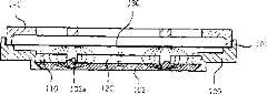
图1示出了传统的微扬声器。如图1所示,所述扬声器包括外壳11,形成其中的内空间。磁铁14安装在外壳11中,沿着垂直方向磁化。磁轭12连同磁铁14形成磁路。上平板15连接到磁铁14以形成所述磁路。所述扬声器还包括产生声音的振膜片16。振膜片16的外边缘连接到外壳11的上端。语音线圈17安装到振膜片16的下端,缠绕成圆柱形。保护板19覆盖外壳11的开放端。印刷电路板(PCB)20连接到外壳11的外表面的预定位置。Figure 1 shows a conventional microspeaker. As shown in FIG. 1, the loudspeaker includes a
另外,多个气孔18形成在外壳11的预定位置,当振膜片振动时,可使空气流畅地循环。In addition, a plurality of
图2是传统的移动终端扬声器的截面图。安置在磁轭12和上平板15之间的气隙中的语音线圈17,连接到振膜片16。这样,当对语音线圈17施加电流,在与上平板15和连接到被磁化的磁铁14上的磁轭12中流动的磁通量的方向相垂直的方向产生电动力,并且,电流在线圈17中流动。所述电动力振动连接到外壳11的振膜片16,因此产生声压。FIG. 2 is a cross-sectional view of a conventional mobile terminal speaker. A
在按上面说明构造的传统微扬声器中,为了构造瘦结构的扬声器,该扬声器所包含部件的尺寸也必须缩小。但是,当决定这种扬声器厚度的磁铁14的体积缩小时,磁通量密度也变低。在这种情况下,声压减小,因此不能获得优良的声音质量。In the conventional microspeaker constructed as described above, in order to construct a thin-structured speaker, the size of the components included in the speaker must also be reduced. However, when the volume of the
另外,在传统的微扬声器中,线圈17连接到振膜片16的下端,垂直缠绕成圆柱形。由于语音线圈在上平板15和磁轭12之间的气隙中安装,当振膜片振动时,连接到振膜片16的语音线圈17可能同上平板15和磁轭12相互碰撞,因此产生故障。In addition, in a conventional micro-speaker, the
为了解决传统扬声器中的这些问题,要求构造一种扬声器,具有瘦小结构,但不缩小磁铁的体积,并且,当振膜片振动时,可以防止语音线圈与上平板或磁轭发生碰撞。In order to solve these problems in conventional loudspeakers, it is required to construct a loudspeaker that has a slim structure without reducing the size of the magnet, and that prevents the voice coil from colliding with the upper plate or the yoke when the diaphragm vibrates.
为了满足这样的需求,有一种建议的瘦扬声器,公开在韩国专利公开出版号2000-59016。根据韩国专利公开出版号2000-59016,构造这种扬声器,以便使语音线圈印刷在振膜片的下表面,并通过外部电力产生预定的磁力,因此扬声器具有瘦细结构。In order to meet such demands, there is a proposed thin speaker disclosed in Korean Patent Laid-Open Publication No. 2000-59016. According to Korean Patent Laid-Open Publication No. 2000-59016, this speaker is constructed so that a voice coil is printed on the lower surface of the diaphragm and a predetermined magnetic force is generated by external power, so that the speaker has a slim structure.
所述语音线圈按螺旋状图形印刷在振膜片的下表面。在这种情况下,该螺旋呈圆形或方形。The voice coil is printed on the lower surface of the diaphragm in a spiral pattern. In this case, the spiral has a circular or square shape.
在这种瘦扬声器中,语音线圈被印刷在振膜片的下表面。因此,同其中线圈被缠绕成圆柱形的传统扬声器相比,这种扬声器的厚度被降至最小。这样,由于这种适用于扬声器的装置的厚度降低了,韩国专利公开出版号2000-59016的扬声器具有的优点是得到了瘦型装置。In this thin speaker, the voice coil is printed on the lower surface of the diaphragm. Therefore, the thickness of this speaker is minimized compared with a conventional speaker in which a coil is wound into a cylindrical shape. Thus, the speaker of Korean Patent Laid-Open Publication No. 2000-59016 has the advantage that a slim device is obtained because the thickness of the device suitable for the speaker is reduced.
但是,这种扬声器也有问题,印刷在振膜片上的语音线圈沿着从振膜片外缘部分形成的端子到振膜片中央的方向绕成螺旋状图形,然后,从振膜片的中央开始,该语音线圈按反方向绕,这样,电流从该端子到振膜片中央的流动方向与电流从中央到该振膜片外缘部分的流动方向相反,因此偏移电磁力。这样,就降低了振动振膜片的力。However, this kind of loudspeaker also has a problem. The voice coil printed on the diaphragm is wound into a spiral pattern along the direction from the terminal formed on the outer edge of the diaphragm to the center of the diaphragm. Initially, the voice coil is wound in the opposite direction, so that the direction of current flow from the terminal to the center of the diaphragm is opposite to the direction of current flow from the center to the outer edge of the diaphragm, thus deflecting the electromagnetic force. In this way, the force of vibrating the diaphragm is reduced.
在这样的瘦扬声器中,在语音线圈和磁物体之间的相互磁感应微弱,所以,很难产生高质量的声压。因此,扬声器的效率遭到损害。In such a thin speaker, the mutual magnetic induction between the voice coil and the magnetic body is weak, so it is difficult to generate high-quality sound pressure. Consequently, the efficiency of the loudspeaker suffers.
特别是,当在小装置中,如移动终端中,采用这种如上所述的、语音线圈印刷在振膜片上的扬声器,由于扬声器的直径大约是15毫米,扬声器的效率低下,不能得到高质量的再生声音。In particular, when such a loudspeaker in which the voice coil is printed on the diaphragm as described above is used in a small device, such as a mobile terminal, since the diameter of the loudspeaker is about 15 mm, the efficiency of the loudspeaker is low, and high performance cannot be obtained. quality reproduced sound.
发明内容Contents of the invention
因此,考虑到现有技术中出现的上述的问题,提出本发明,并且本发明的目的是提供一种用于移动终端的扬声器,具有细小结构,并具有宽频特性和优良的高频失真特性,因此,实现优良的声音质量。Therefore, in consideration of the above-mentioned problems occurring in the prior art, the present invention is proposed, and the purpose of the present invention is to provide a speaker for a mobile terminal, which has a small structure, and has broadband characteristics and excellent high-frequency distortion characteristics, Therefore, excellent sound quality is realized.
为了实现上述目的,本发明提供一种用于移动终端的扬声器,包含:外壳,外壁从所述外壳的外边缘向上延伸预定高度,形成其中的空间;支撑板,安装在所述外壳的下端,以形成磁路;第一磁铁,安置在所述支撑板的上表面的中央,并沿垂直方向磁化;环状第二磁铁,围绕所述第一磁铁安置,并沿垂直方向磁化,以使所述第二磁铁的磁极方向与所述第一磁铁的磁极方向相反;振膜片,安装在所述第一磁铁和所述第二磁铁之上的位置以产生声音,多个语音线圈整体被印刷在所述振膜片上,形成多层,并通过外部驱动电力产生预定的磁力;保护板,覆盖所述外壳的开放端。In order to achieve the above object, the present invention provides a speaker for a mobile terminal, comprising: a housing, an outer wall extending upward from an outer edge of the housing to a predetermined height to form a space therein; a support plate installed at the lower end of the housing, to form a magnetic circuit; the first magnet is placed in the center of the upper surface of the support plate and is magnetized in the vertical direction; the ring-shaped second magnet is placed around the first magnet and is magnetized in the vertical direction so that all The magnetic pole direction of the second magnet is opposite to the magnetic pole direction of the first magnet; the diaphragm is installed at the position above the first magnet and the second magnet to generate sound, and a plurality of voice coils are printed as a whole Multiple layers are formed on the diaphragm, and a predetermined magnetic force is generated by external driving power; a protective plate covers the open end of the casing.
所述振膜片包括:第一聚合树脂膜,所述多个语音线圈包括上语音线圈和下语音线圈,分别印刷在所述第一聚合树脂膜的上表面和下表面;以及第二聚合树脂膜,覆盖每一个所述上语音线圈和所述下语音线圈,防止所述上语音线圈和所述下语音线圈被腐蚀。The diaphragm sheet includes: a first polymer resin film, and the plurality of voice coils include an upper voice coil and a lower voice coil, respectively printed on the upper surface and the lower surface of the first polymer resin film; and a second polymer resin film A membrane covering each of the upper voice coil and the lower voice coil prevents corrosion of the upper voice coil and the lower voice coil.
另外,每一个所述上语音线圈和下语音线圈都被印刷成从形成在所述振膜片外缘部分的输入端子或输出端子开始的螺旋的图形,,以便外部驱动电力从所述输入端子输入,或从所述输出端子输出,通过形成在所述上语音线圈和下语音线圈的所述螺旋中央的通孔,在印刷在所述第一聚合树脂膜的上表面和下表面的所述上语音线圈和所述下语音线圈之间传导电力。In addition, each of the upper voice coil and the lower voice coil is printed as a spiral pattern starting from an input terminal or an output terminal formed on an outer edge portion of the diaphragm, so that external driving power is transmitted from the input terminal input, or output from the output terminal, through the through hole formed in the center of the spiral of the upper voice coil and the lower voice coil, on the upper and lower surfaces of the first polymer resin film printed on the Power is conducted between the upper voice coil and the lower voice coil.
印刷在所述第一聚合树脂膜的上表面的所述上语音线圈的所述螺旋的方向与印刷在所述第一聚合树脂膜的下表面的所述下语音线圈的所述螺旋的方向相反,这样,电流在所述上语音线圈的流动方向与电流在所述下语音线圈的流动方向相同。The direction of the helix of the upper voice coil printed on the upper surface of the first polymer resin film is opposite to the direction of the helix of the lower voice coil printed on the lower surface of the first polymer resin film , so that the flow direction of the current in the upper voice coil is the same as the flow direction of the current in the lower voice coil.
可以在所述振膜片的边缘装配辅助振动片,使所述振膜片平稳地振动。优选地,所述辅助振动片由软橡胶或合成橡胶制成。An auxiliary vibrating plate can be assembled on the edge of the diaphragm to make the diaphragm vibrate smoothly. Preferably, the auxiliary vibrating piece is made of soft rubber or synthetic rubber.
所述支撑板包括支撑突起,在所述支撑板期望的位置支撑所述第一磁铁和所述第二磁铁,以便在所述第一磁铁和所述第二磁铁之间形成气隙。在所述支撑突起的预定位置形成通气孔,当所述振膜片振动时,可使空气通过所述气隙循环。The support plate includes support protrusions to support the first magnet and the second magnet at desired positions of the support plate so as to form an air gap between the first magnet and the second magnet. A vent hole is formed at a predetermined position of the supporting protrusion to allow air to circulate through the air gap when the diaphragm vibrates.
在所述外壳的预定位置可以形成多个通气孔。A plurality of ventilation holes may be formed at predetermined positions of the housing.
通过镶嵌成形过程,所述支撑板与所述外壳集成为单一的结构。The support plate is integrated with the housing into a single structure through an insert forming process.
另外,本发明的所述扬声器可包括连接到所述保护板下表面以提供磁路的第二支撑板,以及连接到所述第二支撑板的下表面并沿垂直方向磁化的第三磁铁,以便所述第三磁铁的磁极方向与所述第一磁铁的磁极方向相反。In addition, the speaker of the present invention may include a second support plate connected to the lower surface of the protective plate to provide a magnetic circuit, and a third magnet connected to the lower surface of the second support plate and magnetized in a vertical direction, So that the magnetic pole direction of the third magnet is opposite to that of the first magnet.
另外,在所述振膜片之上的位置可以形成环状第四磁铁。在这种情况下,所述环状第四磁铁围绕所述第三磁铁安置并磁化,以便所述第四磁铁的磁极方向与所述第三磁铁的磁极方向相反。这样,所述第三磁铁和第四磁铁被安排在所述外壳的内侧和外侧。In addition, a ring-shaped fourth magnet may be formed at a position above the diaphragm. In this case, the ring-shaped fourth magnet is disposed around the third magnet and magnetized such that a magnetic pole direction of the fourth magnet is opposite to that of the third magnet. In this way, the third magnet and the fourth magnet are arranged inside and outside of the case.
为了实现上述的目的,本发明提供一种制造用于移动终端的扬声器的方法,包括:形成与提供磁路的支撑板集成在一起的外壳;将垂直磁化的第一磁铁连接到所述支撑板的上表面,并将沿着与所述第一磁铁的磁极方向相反的方向磁化的第二磁铁连接到所述支撑板的上表面,以便使所述第二磁铁以预定的间隔与所述第一磁铁分隔开;在第一聚合树脂膜的上表面和下表面形成上语音线圈和下语音线圈,用以提供多层,并且,层叠第二聚合树脂膜以防止上语音线圈和下语音线圈的腐蚀,绝缘上语音线圈和下语音线圈,这样,成形振膜片;将所述振膜片连接到所述外壳,以便所述振膜片的外边缘由所述外壳的上端来支撑;在所述外壳上安置保护板,覆盖所述外壳的开放端;把所述上语音线圈和所述下语音线圈的输入端子和输出端子焊接到印刷电路板(PCB)的端子片。In order to achieve the above objects, the present invention provides a method of manufacturing a speaker for a mobile terminal, comprising: forming a housing integrated with a support plate providing a magnetic circuit; connecting a vertically magnetized first magnet to the support plate the upper surface of the support plate, and attach a second magnet magnetized in a direction opposite to the magnetic pole direction of the first magnet to the upper surface of the support plate so that the second magnet is separated from the first magnet at a predetermined interval. A magnet is separated; an upper voice coil and a lower voice coil are formed on the upper surface and the lower surface of the first polymer resin film to provide multiple layers, and the second polymer resin film is laminated to prevent the upper voice coil and the lower voice coil Corrosion of insulating the upper voice coil and the lower voice coil, thus forming the diaphragm; connecting the diaphragm to the housing so that the outer edge of the diaphragm is supported by the upper end of the housing; A protective plate is arranged on the shell to cover the open end of the shell; the input terminal and the output terminal of the upper voice coil and the lower voice coil are welded to the terminal pieces of the printed circuit board (PCB).
振膜片的成形包括在所述第一聚合树脂膜的上表面和下表面涂黏合剂,并把铜膜连接到所述第一聚合树脂膜的上表面和下表面的每一个,并蚀刻所述铜膜的表面,这样,形成所述上语音线圈和所述下语音线圈中每一个的图形。The forming of the diaphragm sheet includes coating an adhesive on the upper surface and the lower surface of the first polymer resin film, and connecting a copper film to each of the upper surface and the lower surface of the first polymer resin film, and etching the the surface of the copper film, thus forming the pattern of each of the upper voice coil and the lower voice coil.
附图说明Description of drawings
下面结合附图的详细说明将使本发明的上述和其他目的、特征和其他优点更加明了。附图包括:The following detailed description in conjunction with the accompanying drawings will make the above and other objects, features and other advantages of the present invention more apparent. The attached drawings include:
图1是传统的用于移动终端的扬声器的透视图;FIG. 1 is a perspective view of a conventional speaker for a mobile terminal;
图2是图1的扬声器的截面图;Fig. 2 is a sectional view of the loudspeaker of Fig. 1;
图3是根据本发明第一实施例的用于移动终端的扬声器的透视图;3 is a perspective view of a speaker for a mobile terminal according to a first embodiment of the present invention;
图4是图3的扬声器的截面图;Fig. 4 is a cross-sectional view of the loudspeaker of Fig. 3;
图5是包含在图3的扬声器中的振膜片的详细截面图;FIG. 5 is a detailed cross-sectional view of a diaphragm included in the loudspeaker of FIG. 3;
图6是示出图5的振膜片上表面的平面图;Fig. 6 is a plan view showing the upper surface of the diaphragm of Fig. 5;
图7是示出图5的振膜片下表面的平面图;Fig. 7 is a plan view showing the lower surface of the diaphragm of Fig. 5;
图8是根据本发明第二实施例的用于移动终端的扬声器的透视图;8 is a perspective view of a speaker for a mobile terminal according to a second embodiment of the present invention;
图9是图8的扬声器的截面图;Fig. 9 is a cross-sectional view of the loudspeaker of Fig. 8;
图10是根据本发明第三实施例的用于移动终端的扬声器的截面图;以及10 is a cross-sectional view of a speaker for a mobile terminal according to a third embodiment of the present invention; and
图11是根据本发明第四实施例的用于移动终端的扬声器的截面图。FIG. 11 is a cross-sectional view of a speaker for a mobile terminal according to a fourth embodiment of the present invention.
具体实施方式Detailed ways
在下文中,将参考附图详细说明本发明的实施例。Hereinafter, embodiments of the present invention will be described in detail with reference to the accompanying drawings.
对附图做标记,在所有各不相同的附图中,使用相同的参考标号指示相同或近似的部分。To label the drawings, the same reference numerals are used to designate the same or similar parts throughout the different drawings.
图3是根据本发明第一实施例的、用于移动终端的扬声器的透视图。图4是图3的扬声器的截面图。下面将参考图3和图4说明根据第一实施例的扬声器。FIG. 3 is a perspective view of a speaker for a mobile terminal according to a first embodiment of the present invention. FIG. 4 is a cross-sectional view of the speaker of FIG. 3 . A speaker according to a first embodiment will be described below with reference to FIGS. 3 and 4 .
根据本发明的第一实施例,用于移动终端的扬声器包括:外壳100,支撑板102,第一磁铁120,第二磁铁110,振膜片130,以及保护板140。外壳100,利用从外壳100的外边缘向上延伸到预定高度的外壁101形成其中的空间。支撑板102安装在外壳100的下端,以提供磁路。第一磁铁120被安置在支撑板102的上表面的中央,并沿垂直方向磁化。第二磁铁110围绕第一磁铁120安置,并沿垂直方向磁化,以便使第二磁铁110的磁极方向与第一磁铁的磁极方向相反。振膜片130安装在第一磁铁120和第二磁铁110之上的位置以产生声音。多个语音线圈整体印刷在振膜片130上,以形成多层,并通过外部驱动电力生成预定的磁力。保护板140覆盖外壳100的开放端。According to the first embodiment of the present invention, a speaker for a mobile terminal includes: a
为了防止第一磁铁120和第二磁铁110磁力的损失,优选地,外壳100用非磁性材料制成,并通过注塑成形过程来制造。In order to prevent the loss of the magnetic force of the
另外,根据本发明的第一实施例,外壳100具有圆形。但是,外壳100也可以有不同的形状,例如,矩形、椭圆形、轨道(track)形,而不限于圆形。In addition, according to the first embodiment of the present invention, the
优选地,支撑板102由具有高透磁性的铁磁性材料制成,例如钢。Preferably, the
另外,支撑板102和外壳100可以分开制造,然后互相组装在一起。或者,支撑板102和外壳100可以相互集成为单一的结构。在支撑板102和外壳100单独制造的情况下,支撑板102的边缘和外壳100具有对应的倾斜表面或者阶梯表面,以便支撑板102和外壳100在所述倾斜表面或阶梯表面处互相组装在一起。而在支撑板102与外壳100相互集成的情况下,在外壳100的成形过程期间,支撑板102通过镶嵌成形过程来制造。Alternatively, the
另外,支撑突起102a形成在支撑板102的预定位置,在支撑板102的期望位置支撑第一磁铁120和第二磁铁110。In addition, a
支撑突起102a位于环绕第一磁铁120的外圆周表面的地方,以便在第一磁铁120和第二磁铁110之间形成气隙。通过支撑突起102a,第一磁铁120和第一磁铁110被支撑在支撑板102上的期望位置。The supporting
另外,多个通气孔102b形成在支撑突起102a的预定位置,以便当振膜片130振动时,使空气通过所述气隙循环,因而使振膜片130平稳地振动。In addition, a plurality of
在这种情况下,优选地,通气孔102b相互对称地形成。也即,当对称地形成通气孔102b,在振膜片130振动期间,可以避免杂乱的振动,因此防止损害声音质量。In this case, preferably, the vent holes 102b are formed symmetrically to each other. That is, when the vent holes 102b are symmetrically formed, during the vibration of the
根据第一实施例,通气孔102b形成在支撑突起102a的预定位置。但是,通气孔102b也可以形成在其他位置,不限于支撑突起102a上。According to the first embodiment, the
例如,通气孔102b可以形成在外壳100。即使通气孔102b形成在外壳100,优选地,通气孔102b要对称地形成。For example, a
第一磁铁120具有圆形以适合外壳100的形状,而第二磁铁110具有围绕第一磁铁的圆环形状。The
在本发明中,第一磁铁120和第一磁铁110必须磁化,以使第一磁铁120的磁极方向与第二磁铁110的磁极方向相反。In the present invention, the
也即,如图4所示,当磁化第一磁铁120,使北极位于第一磁铁120的上端,南极位于第一磁铁120的下端,磁化第二磁铁110,使南极位于第二磁铁110的上端,北极位于第二磁铁110的下端,因此在磁场的水平方向形成磁通量。That is, as shown in FIG. 4 , when the
第一磁铁120和第二磁铁110可使用不同的粘合方法粘合在一起。优选地,使用热片或热粘合带把第一磁铁120和第二磁铁110互相连接起来。The
在本发明的第一实施例中,优选地,第一磁铁120和第二磁铁110中的每一个由体积小而磁力强的钕磁铁构成。In the first embodiment of the present invention, preferably, each of the
钕磁铁是稀有的地球磁铁,具有很强的磁力,广泛用于轻便、瘦细、小巧、紧凑的高技术产品。钕磁铁型扬声器整体安装在笔记本电脑、小尺寸个人电脑、瘦电脑或LCD监视器等产品中。Neodymium magnets are rare earth magnets with strong magnetic force and are widely used in light, thin, small and compact high-tech products. Neodymium magnet type speakers are integrally installed in products such as notebook computers, small-sized personal computers, thin computers, or LCD monitors.
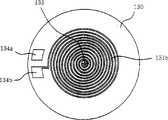
振膜片130安装在第一磁铁120和第二磁铁110之上的位置,印刷有多个语音线圈131以形成所述多层。本发明第一实施例所使用的振膜片130的构造,在图5至图7详细示出。The
图5是图3的扬声器包含的所述振膜片的详细截面图。图6是示出图5的振膜片的上表面的平面图。图7是示出图5的振膜片的下表面的平面图。FIG. 5 is a detailed cross-sectional view of the diaphragm included in the loudspeaker of FIG. 3 . FIG. 6 is a plan view showing an upper surface of the diaphragm sheet of FIG. 5 . FIG. 7 is a plan view showing the lower surface of the diaphragm sheet of FIG. 5 .
振膜片130包括第一聚合树脂膜132。上语音线圈131a和下语音线圈131b分别印刷在第一聚合树脂膜132的上表面和下表面。两个第二聚合树脂膜133分别覆盖上语音线圈131a和下语音线圈131b,以防止上线圈131a和下线圈131b被腐蚀。The
也即,上线圈131a和下线圈131b被印刷在第一聚合树脂膜132。为了装配这样的振膜片130,在第一聚合树脂膜132的上下表面要涂黏合剂。接下来,把铜膜连接到第一聚合树脂膜132上表面和下表面中的每一个。铜膜的表面被蚀刻,因此形成上语音线圈131a和下语音线圈131b的每一个的图形。然后,第二聚合树脂膜133覆盖上语音线圈131a和下语音线圈131b中的每一个,以防止上语音线圈131a和下语音线圈131b被腐蚀。That is, the
就这样,导电材料,例如铜,涂在振膜片130上,形成上语音线圈131a和下语音线圈131b。因此,上语音线圈131a和下语音线圈131b与振膜片130集成为单一的结构。In this way, a conductive material, such as copper, is coated on the
在这种情况下,上语音线圈131a和下语音线圈131b中的每一个具有几个微米的厚度。上语音线圈131a和下语音线圈131b中的每一个具有螺旋的图形。In this case, each of the
在详细说明中,输入端子134a和输出端子134b形成在振膜片130的外缘部分,外部驱动电分别输入到输入端子134a和从输出端子134b输出。上语音线圈131a和下语音线圈131b被印刷成从输入端子134a和输出端子134b开始的螺旋图形。In detail, the
根据本发明的第一实施例,由于上语音线圈131a和下语音线圈131b被印刷在振膜片130上形成双层,在上语音线圈131a和下语音线圈131b的螺旋的中央形成通孔135,在印刷在第一聚合树脂膜132上表面的上语音线圈131a和印刷在第一聚合树脂膜132下表面的下语音线圈131b之间传导电力。According to the first embodiment of the present invention, since the
按照上述构造的振膜片130按下述的过程来操作。驱动电输入到输入端子134a。然后,该驱动电在以螺旋图形印刷在第一聚合树脂膜132上表面的上语音线圈131a流动,并通过通孔135传导到印刷在第一聚合树脂膜132下表面的下语音线圈131b。接着,该驱动电在以螺旋图形印刷在第一聚合树脂膜132下表面的下语音线圈131b流动,然后从输出端子134b输出。The
在这种情况下,上语音线圈131a和下语音线圈131b必须分别印刷在第一聚合树脂膜132的上表面和下表面,以便使上语音线圈131a的螺旋方向与下语音线圈131b的螺旋方向相反。In this case, the
例如,在上语音线圈131a被印刷成具有顺时针方向的螺旋图形的情况下,下语音线圈131b必须被印刷成逆时针方向的螺旋图形。反过来,在上语音线圈131a被印刷成具有逆时针方向的螺旋图形的情况下,下语音线圈131b必须被印刷成顺时针方向的螺旋图形。For example, in case the
这样,当上语音线圈131a的螺旋方向与下语音线圈131b的螺旋方向相反,电流在上语音线圈131a中流动的方向与电流在下语音线圈131b中流动的方向相同,因此,加倍电流的效率。In this way, when the helical direction of the
在本发明的振膜片130中,按照这种方式成对地印刷语音线圈131,电流在上语音线圈131a中流动的方向与电流在下语音线圈131b中流动的方向相同,因此,加倍电流的效率,并提高振动振膜片的力量。In the
在所公开的第一实施例中,振膜片130上印刷上语音线圈131a和下语音线圈131b,形成双层。但是,根据本发明,也可以在振膜片130上印刷多个语音线圈131,形成多层。In the disclosed first embodiment, the
另外,可以通过厚度和上语音线圈131a和下语音线圈131b中每一个的图形宽度控制扬声器的阻抗。可以在所述扬声器上附加无纺纤维,以控制气流。In addition, the impedance of the speaker can be controlled by the thickness and pattern width of each of the
在外壳100的预定位置形成印刷电路板(PCB)108的端子片(没有示出),在此焊接语音线圈131的输入端子134a和输出端子134b。A terminal piece (not shown) of a printed circuit board (PCB) 108 is formed at a predetermined position of the
在按照上述构造的扬声器中,环形第二磁铁110环绕第一磁铁120安置。磁化第一磁铁120和第二磁铁110,使第一磁铁120的磁极方向与第二磁铁110的磁极方向相反。另外,在第一磁铁120和第二磁铁110的上方形成语音线圈131。这样,穿过语音线圈131的磁通量的方向与语音线圈131中电流流动的方向垂直。In the speaker configured as described above, the annular
在本发明的磁路(magnet circuit)中,磁通量具有水平方向,以便该磁通量的方向与语音线圈131中电流流动的方向垂直。所述磁路振动粘合到外壳100上的振膜片130,以产生声压,因此实现高磁效率。In the magnet circuit of the present invention, the magnetic flux has a horizontal direction so that the direction of the magnetic flux is perpendicular to the direction of current flow in the
构造本发明的扬声器,使第一磁铁120所产生磁场的方向与第二磁铁110所产生磁场的方向相同。这样,第一磁铁120的磁力线方向与第二磁铁110的磁力线的方向相同,因此提高了磁通量,当输入同样数量的电力可以获得较高的输出。The loudspeaker of the present invention is constructed such that the direction of the magnetic field generated by the
下面说明制造根据本发明的用于移动终端的扬声器的过程。首先,制造要与外壳100集成的、提供磁路的的支撑板102。沿着垂直方向磁化的第一磁铁120连接到支撑板的上表面。接下来,沿着与第一磁铁120的磁极方向相反的方向磁化的第二磁铁110连接到支撑板102,使第二磁铁110以预定间隔与第一磁铁120分隔开。具有印刷在第一聚合树脂膜132的上下表面的语音线圈的振膜片被安装在外壳100的上端。然后,保护板140被安置在外壳100上,覆盖外壳100的开放端。A process of manufacturing a speaker for a mobile terminal according to the present invention is explained below. First, the supporting
另外,语音线圈131的输入端子134a和输出端子134b焊接到PCB108的所述端子片的预定部分。这样,完成所述扬声器的制造。In addition, the
由于上语音线圈131a和下语音线圈131b印刷在振膜片130上形成双层,并且电流在上语音线圈131a中的流动方向与电流在下语音线圈131b中的流动方向相同,本发明的所述扬声器,与传统的瘦扬声器相比,加倍了电流效率,因此提高了对振膜片的振动力量。Since the
另外,构造本发明的扬声器,使第一磁铁120和第二磁铁110安排在外壳100的内部和外部,这样,语音线圈131同第一磁铁120和第二磁铁110之间的磁作用变强。因此,产生高质量的声压,提高了扬声器的效率。In addition, the speaker of the present invention is constructed so that the
图8是示出根据本发明第二实施例的用于移动终端的扬声器的透视图。FIG. 8 is a perspective view showing a speaker for a mobile terminal according to a second embodiment of the present invention.
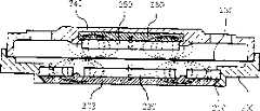
第二实施例的扬声器包括:外壳200;第一支撑板202,连接到外壳200的下端,以提供磁路;第一磁铁220,安置在第一支撑板202上表面的中央,并垂直地磁化;环形第二磁铁210,环绕第一磁铁220安置,并垂直磁化,使第二磁铁210的磁极方向与第一磁铁220的磁极方向相反;另外,振膜片230,用来产生声音,装配在第一磁铁220和第二磁铁210上方的位置;多个语音线圈231,整体印刷在振膜片230上形成多层,并产生预定的磁力;所述扬声器还有保护板240,覆盖外壳200的开放端。The loudspeaker of the second embodiment includes: a
在本发明的第二实施例中,如图9所示,第二支撑板250连接到保护板240的下表面以提供磁路。另外,第三磁铁260安装到第二支撑板250的下表面,并被垂直磁化,使第三磁铁260的磁极方向与第一磁铁220的磁极方向相反。In the second embodiment of the present invention, as shown in FIG. 9 , a
也就是,如图9所示,第二实施例的扬声器包含被磁化的第三磁铁260,使得,当第一磁铁220被磁化,北极位于第一磁铁220的上端并且南极位于第一磁铁220的下端时,北极位于第三磁铁260的下端并且南极位于第三磁铁260的上端。That is, as shown in FIG. 9, the speaker of the second embodiment includes a
这样,第二实施例的扬声器还包含圆形第三磁铁260,装配在振膜片230上方的位置,因而对振膜片230提供强电磁力,并使振膜片230的垂直振动更平稳的进行。In this way, the loudspeaker of the second embodiment also includes a circular
参见所述扬声器的上部,优选地,第二支撑板250通过镶嵌成形过程与保护板240集成。在这种情况下,在第二支撑板250的边缘形成阶梯部分,由保护板240来支撑。Referring to the upper part of the speaker, preferably, the
第二实施例的振膜片230的构造与第一实施例的振膜片130的构造仍然相同。根据第二实施例,语音线圈231整体印刷在振膜片230上,用以形成多层。The structure of the
振膜片230包括第一聚合树脂膜。语音线圈231分别印刷在所述第一聚合树脂膜的上下表面。第二聚合树脂膜覆盖每个语音线圈,防止语音线圈231被腐蚀。在这种情况下,每个语音线圈被印刷成螺旋图形。The
另外,在所述螺旋的中央形成通孔,用于在印刷在所述第一聚合树脂膜的上表面的语音线圈231同印刷在所述第一聚合树脂膜的下表面的语音线圈231之间传导电力。首先,驱动电力输入到输入端子。电在以螺旋图形印刷在所述第一聚合树脂膜的上表面的语音线圈231中流动,然后,通过所述通孔传导到印刷在所述第一聚合树脂膜的下表面的语音线圈231。接下来,电在以螺旋图形印刷在所述第一聚合树脂膜的下表面的语音线圈231中流动,然后,从输出端子输出。In addition, a through hole is formed in the center of the spiral for between the voice coil 231 printed on the upper surface of the first polymer resin film and the voice coil 231 printed on the lower surface of the first polymer resin film. conduct electricity. First, drive power is input to the input terminal. Electricity flows in the voice coil 231 printed on the upper surface of the first polymer resin film in a spiral pattern, and then, is conducted to the voice coil 231 printed on the lower surface of the first polymer resin film through the through hole. Next, electricity flows in the voice coil 231 printed in a spiral pattern on the lower surface of the first polymer resin film, and then, is output from the output terminal.
在这种情况下,语音线圈231必须印刷在所述第一聚合树脂膜的上下表面,以便上语音线圈231的所述螺旋的方向与下语音线圈231的所述螺旋的方向相反。In this case, the voice coil 231 must be printed on the upper and lower surfaces of the first polymer resin film so that the direction of the spiral of the upper voice coil 231 is opposite to that of the lower voice coil 231 .
这样,电流在上语音线圈231中流动的方向与电流在下语音线圈231中流动的方向相同,因此使电流效率加倍。In this way, the direction of current flowing in the upper voice coil 231 is the same as the direction of current flowing in the lower voice coil 231, thus doubling the current efficiency.
另外,在第一支撑板202的预定位置形成支撑突起202a,用以在第一支撑板的期望位置支撑第一磁铁220和第二磁铁210。在支撑突起202a的预定位置形成多个通气孔202b,当振膜片230振动时,使空气通过气隙循环,因此使振膜片230平稳地振动。In addition, a support protrusion 202a is formed at a predetermined position of the
在这种情况下,优选地,通气孔202b相互对称地形成。通气孔202b也可以形成在其他位置,不限于在支撑突起202a。In this case, preferably, the vent holes 202b are formed symmetrically to each other. The vent hole 202b may also be formed at other positions, not limited to the support protrusion 202a.
根据所述第二实施例的瘦扬声器包含平板振膜片230。语音线圈231印刷在振膜片230的相同平面上。由于语音线圈231成对地印刷,并且电流在上语音线圈231中的流动方向与电流在下语音线圈231中的流动的方向相同,与传统的瘦扬声器相比,电流效率被加倍,因此提高了对振膜片230的振动力量。第一磁铁220和第二磁铁210被安装在所述扬声器的下部,以便使第一磁铁220和第二磁铁210安排在外壳200的中间部分和外缘部分。另外,圆形第三磁铁260装配在振膜片230上方的位置。第二支撑板250安装在第三磁铁260上。因此,得到强磁路,由此产生高质量的声压,因而提高了所述扬声器的效率。The thin speaker according to the second embodiment includes a
图10是根据本发明第三实施例的用于移动终端的扬声器的截面图。在第三实施例的扬声器中,磁铁安装在所述扬声器的上部,使所述磁铁安排在外壳的中间部分和外缘部分,因此增强磁场。FIG. 10 is a cross-sectional view of a speaker for a mobile terminal according to a third embodiment of the present invention. In the speaker of the third embodiment, magnets are mounted on the upper portion of the speaker so that the magnets are arranged in the middle portion and the outer edge portion of the casing, thereby enhancing the magnetic field.
根据所述第三实施例,第二支撑板350安装在保护板340的下表面,用以提供磁路。第三磁铁360和第四磁铁370安装到第二支撑板350的下表面。在这种情况下,垂直磁化第三磁铁360,使第三磁铁360的磁极方向与第一磁铁320的磁极方向相反。环形第四磁铁370环绕第三磁铁360。According to the third embodiment, the
在这种情况下,磁化第四磁铁370,以便使第四磁铁370的磁极方向与第三磁铁360的磁极方向相反。In this case, the
在详细说明中,如图10所示,当第一磁铁320被磁化以使北极位于第一磁铁320的上端并且南极位于第一磁铁320的下端时,第二磁铁310被磁化,以便使南极位于第二磁铁310的上端并且北极位于第二磁铁310的下端,因此在磁场的水平方向形成磁通量。另外,第三磁铁360被磁化,以便使其磁极方向与第一磁铁320的磁极方向相反。因此,北极位于第三磁铁360的下端,而南极位于第三磁铁的360的上端。另外,第四磁铁370被磁化,以便使北极位于第四磁铁370的上端并且南极位于第四磁铁370的下端。In detail, as shown in FIG. 10, when the first magnet 320 is magnetized so that the north pole is located at the upper end of the first magnet 320 and the south pole is located at the lower end of the first magnet 320, the second magnet 310 is magnetized so that the south pole is located at the lower end of the first magnet 320. The upper end and the north pole of the second magnet 310 are located at the lower end of the second magnet 310, thus forming magnetic flux in the horizontal direction of the magnetic field. In addition, the
也就是,装配在所述扬声器上部的第三磁铁360和第四磁铁370的磁极方向分别与第一磁铁320和第二磁铁310的磁极方向相反。That is, the magnetic pole directions of the
这样,根据第三实施例的的扬声器还包括在振膜片330上方位置的圆形第三磁铁360和环形第四磁铁370,因此对振膜片330提供强电磁力,由此增强所述扬声器的性能。In this way, the speaker according to the third embodiment further includes a circular
图11是根据本发明第四实施例的用于移动终端的扬声器的截面图。根据第四实施例,辅助振动片380连接到振膜片330的边缘,使振膜片330平稳地振动。FIG. 11 is a cross-sectional view of a speaker for a mobile terminal according to a fourth embodiment of the present invention. According to the fourth embodiment, the auxiliary vibrating
优选地,辅助振动片380由软橡胶或合成橡胶制成。Preferably, the auxiliary vibrating
另外,引线390装在振膜片的预定位置,向印刷在振膜片330的所述语音线圈输入信号,使外部信号可以传导到所述语音线圈。In addition, the
根据第四实施例,由软橡胶或合成橡胶制成的辅助振动片380连接到振膜片330的边缘,因此使振膜片330可以更平稳地振动。According to the fourth embodiment, the auxiliary vibrating
另外,根据第四实施例,第三磁铁360和第四磁铁370装配在振膜片330上方的预定位置。当然,连接到振膜片330的辅助振动片380也可以应用在根据第一实施例或第二实施例的扬声器。In addition, according to the fourth embodiment, the
如上所述,本发明提供用于移动终端的扬声器,构造这种扬声器,使语音线圈整体印刷在振膜片上,并且第一磁铁和第二磁铁被安排在外壳的中间部分和外缘部分以提供内外磁路的结合,因此,显著地减少扬声器的厚度,并产生高质量的声压。As described above, the present invention provides a speaker for a mobile terminal, which is configured such that a voice coil is integrally printed on a diaphragm, and a first magnet and a second magnet are arranged at a middle portion and an outer edge portion of a housing to Provides a combination of internal and external magnetic circuits, thus significantly reducing the speaker's thickness and producing high-quality sound pressure.
另外,语音线圈被印刷在振膜片上,以增强所述振膜片的强度,因而实现瘦而平的结构,同时保证宽频特性和良好的高频失真特性,因此提供自然而清晰的声音。In addition, the voice coil is printed on the diaphragm to enhance the strength of the diaphragm, thereby achieving a thin and flat structure while ensuring broadband characteristics and good high-frequency distortion characteristics, thus providing natural and clear sound.
在内外磁路的结合中,两个磁铁被安排在外壳的中间部分和外缘部分,以便使一个磁铁的磁极方向与其余一个磁铁的磁极方向相反,因此形成相斥的磁场。在这种情况下,在水平方向生成磁路,以便使磁通量的方向与电流在所述语音线圈中流动的方向垂直,因此实现高磁效率。In the combination of the inner and outer magnetic circuits, two magnets are arranged in the middle part and the outer edge part of the casing so that the magnetic pole direction of one magnet is opposite to that of the other magnet, thus forming a repelling magnetic field. In this case, the magnetic circuit is generated in the horizontal direction so that the direction of the magnetic flux is perpendicular to the direction in which the current flows in the voice coil, thus achieving high magnetic efficiency.
另外,平板语音线圈与具有聚合树脂膜的振膜片集成,因此简化了所述振膜片与所述语音线圈的组装过程,而这个过程被认为是重要的过程,因此显著降低了在所述语音线圈与所述振膜片组装中可能发生的故障。In addition, the planar voice coil is integrated with the diaphragm with a polymer resin film, thus simplifying the process of assembling the diaphragm with the voice coil, which is considered to be an important process, thus significantly reducing the Possible faults in the assembly of the voice coil and the diaphragm.
因此,减少了生产扬声器所需要的超前时间。Therefore, the lead time required to produce the loudspeaker is reduced.
另外,语音线圈被印刷在振膜片的上下表面,以便使一个语音线圈的螺旋的方向与其余一个语音线圈的螺旋的方向相反。因此,电流在一个语音线圈中的流动方向与电流在其余一个语音线圈中的流动方向相同,这样,使电流效率加倍,因此提供高性能的扬声器。In addition, the voice coils are printed on the upper and lower surfaces of the diaphragm so that the helical direction of one voice coil is opposite to that of the other voice coil. Therefore, the current flows in one voice coil in the same direction as the current flows in the remaining one of the voice coils, thus doubling the current efficiency and thus providing a high-performance speaker.
另外,为了使气隙中的效率增至最大,具有不同极性的磁铁被安排在外壳的内部和外部,具有相同极性的磁铁被安排垂直地互相面对,因此,提供了一种夹层结构的扬声器。这样的结构中,由于互斥磁场,使得磁通量在水平方向产生。In addition, in order to maximize the efficiency in the air gap, magnets with different polarities are arranged inside and outside the housing, and magnets with the same polarity are arranged to face each other vertically, thus, providing a sandwich structure of speakers. In such a structure, the magnetic flux is generated in the horizontal direction due to the mutual repulsion of the magnetic fields.
尽管为了说明的目的,通过优选实施例公开了本发明,本领域的普通技术人员能够理解,在不脱离本发明的权利要求书所定义的精神和范围内,可以做各种修改、添加和替换。Although the present invention has been disclosed through preferred embodiments for the purpose of illustration, those skilled in the art can understand that various modifications, additions and substitutions can be made without departing from the spirit and scope defined by the claims of the present invention .
Claims (42)
Applications Claiming Priority (2)
| Application Number | Priority Date | Filing Date | Title |
|---|---|---|---|
| KR1020040021691AKR100547357B1 (en) | 2004-03-30 | 2004-03-30 | Speaker for mobile terminal and manufacturing method thereof |
| KR21691/2004 | 2004-03-30 |
Publications (1)
| Publication Number | Publication Date |
|---|---|
| CN1678131Atrue CN1678131A (en) | 2005-10-05 |
Family
ID=35050379
Family Applications (1)
| Application Number | Title | Priority Date | Filing Date |
|---|---|---|---|
| CNA2004100716770APendingCN1678131A (en) | 2004-03-30 | 2004-07-21 | Speaker for mobile terminal and manufacturing method thereof |
Country Status (4)
| Country | Link |
|---|---|
| US (1) | US20050220320A1 (en) |
| JP (1) | JP2005286984A (en) |
| KR (1) | KR100547357B1 (en) |
| CN (1) | CN1678131A (en) |
Cited By (21)
| Publication number | Priority date | Publication date | Assignee | Title |
|---|---|---|---|---|
| CN101529872B (en)* | 2006-10-30 | 2012-06-06 | 索尼爱立信移动通讯股份有限公司 | Speaker module for electronic device |
| CN102595289A (en)* | 2012-02-24 | 2012-07-18 | 精拓丽音科技(北京)有限公司 | Wireless charging receiving terminal integrated with loudspeaker |
| CN102970641A (en)* | 2012-10-30 | 2013-03-13 | 深圳天珑无线科技有限公司 | Voice coil and voice diaphragm integrated structure, speaker and mobile terminal |
| CN103024638A (en)* | 2012-11-25 | 2013-04-03 | 歌尔声学股份有限公司 | Electroacoustic transducer |
| CN104822107A (en)* | 2015-03-23 | 2015-08-05 | 马根昌 | All direction open type sound box |
| CN105357623A (en)* | 2015-11-10 | 2016-02-24 | 重庆夏朗科技有限公司 | Washer, magnet and rivet assembly method |
| WO2017088712A1 (en)* | 2015-11-23 | 2017-06-01 | 许扬 | Flat and moving-coil combined-type vibrating diaphragm assembly |
| CN107251572A (en)* | 2015-02-27 | 2017-10-13 | 日东电工株式会社 | Acoustic resistance, acoustic resistance member having the same, and audio equipment |
| CN107534811A (en)* | 2015-07-22 | 2018-01-02 | 谷歌有限责任公司 | Apparatus and method for the high-performance electric magnetic speaker based on individual layer |
| CN109660926A (en)* | 2019-02-28 | 2019-04-19 | 汉得利(常州)电子股份有限公司 | A kind of ultra thin handset loudspeaker made of printing voice coil |
| CN109923875A (en)* | 2016-11-04 | 2019-06-21 | 三星电子株式会社 | Planar magnet loudspeaker |
| CN110022516A (en)* | 2018-01-08 | 2019-07-16 | 深圳市韶音科技有限公司 | Bone conduction loudspeaker |
| CN110351635A (en)* | 2018-04-06 | 2019-10-18 | N斯特龙株式会社 | Magnet structure and panel vibration formula audio generating device including the magnet structure |
| CN110546964A (en)* | 2016-10-04 | 2019-12-06 | 普拉德内什·莫哈尔 | Components for sound generation |
| CN110572746A (en)* | 2019-08-19 | 2019-12-13 | 歌尔股份有限公司 | A conducting film and sound generating mechanism for sound generating mechanism |
| CN111356066A (en)* | 2018-12-21 | 2020-06-30 | 惠州益铂电子有限公司 | Hot press forming's two-sided aluminium wire voice coil loudspeaker voice coil layer vibrating diaphragm flat loudspeaker |
| CN111800714A (en)* | 2019-07-23 | 2020-10-20 | 深圳市豪恩声学股份有限公司 | Speaker and electronic equipment |
| CN111866676A (en)* | 2019-04-29 | 2020-10-30 | 美商富迪科技股份有限公司 | Movable embedded microstructure and micro speaker |
| CN112019979A (en)* | 2020-04-17 | 2020-12-01 | 颜君玲 | Planar coil diaphragm of loudspeaker, loudspeaker and application of loudspeaker |
| CN113490119A (en)* | 2021-05-20 | 2021-10-08 | 汉得利(常州)电子股份有限公司 | Sound membrane set, laminating jig, manufacturing method and sound production device |
| WO2025097751A1 (en)* | 2023-11-06 | 2025-05-15 | 成都水月雨科技有限公司 | Annular dual-suspension quad-magnet planar magnetic driver for in-ear headphone |
Families Citing this family (46)
| Publication number | Priority date | Publication date | Assignee | Title |
|---|---|---|---|---|
| CN1992996B (en)* | 2005-12-30 | 2012-02-29 | 丁轶 | Detachable supporting structure for loudspeaker diaphragm |
| JP2008092028A (en)* | 2006-09-29 | 2008-04-17 | Matsushita Electric Ind Co Ltd | Speaker |
| JP4845677B2 (en) | 2006-10-31 | 2011-12-28 | 三洋電機株式会社 | Electroacoustic transducer |
| JP2008118217A (en)* | 2006-10-31 | 2008-05-22 | Sanyo Electric Co Ltd | Electroacoustic transducer |
| TW200829053A (en)* | 2006-12-21 | 2008-07-01 | Global Target Entpr Inc | Thin-film type sound source output apparatus |
| US20110133577A1 (en)* | 2008-08-18 | 2011-06-09 | In Ho Lee | Horizontal linear vibration device |
| WO2010122605A1 (en)* | 2009-04-23 | 2010-10-28 | 三菱電機エンジニアリング株式会社 | Electromagnetic converter |
| KR101111894B1 (en)* | 2009-05-12 | 2012-02-14 | 주식회사 비에스이 | Multifunction micro speaker |
| KR101057078B1 (en)* | 2009-05-12 | 2011-08-16 | 주식회사 비에스이 | Multifunction micro speaker |
| KR101213964B1 (en)* | 2010-06-11 | 2012-12-20 | 주식회사 엑셀웨이 | Voice film of multi layered structure for flat type speaker |
| JP5540920B2 (en)* | 2010-06-17 | 2014-07-02 | ソニー株式会社 | Acoustic transducer |
| JP5598109B2 (en)* | 2010-06-17 | 2014-10-01 | ソニー株式会社 | Acoustic transducer |
| JP5540921B2 (en)* | 2010-06-17 | 2014-07-02 | ソニー株式会社 | Acoustic transducer |
| US8300873B2 (en) | 2010-07-14 | 2012-10-30 | American Greetings Corporation | Low profile greeting card speaker |
| DK3288295T3 (en) | 2011-03-30 | 2021-10-25 | Kaetel Systems Gmbh | Procedure for reproducing a sound scene |
| KR101147904B1 (en)* | 2011-05-11 | 2012-05-24 | 주식회사 엑셀웨이 | Flat type speaker having multi-layer pcb pattern voice coil film |
| US8948441B2 (en) | 2012-03-14 | 2015-02-03 | Harman International Industries, Inc. | Planar speaker system |
| US8983112B2 (en)* | 2012-03-14 | 2015-03-17 | Harman International Industries, Incorporated | Planar speaker system |
| KR101351892B1 (en)* | 2012-05-18 | 2014-01-22 | 주식회사 이엠텍 | Sound transducer |
| JP5700704B2 (en)* | 2012-10-29 | 2015-04-15 | 賢太 田中 | Speaker device |
| WO2014137010A1 (en)* | 2013-03-07 | 2014-09-12 | 주식회사 엑셀웨이 | Plate-type speaker comprising vibration plate integrally formed with voice film |
| CN203661282U (en)* | 2013-12-11 | 2014-06-18 | 瑞声光电科技(常州)有限公司 | Magnetic circuit system and loudspeaker provided with magnetic circuit system |
| CN103873992A (en)* | 2014-02-26 | 2014-06-18 | 谭红梅 | Method and device for improving power of loudspeaker driver |
| JP6499408B2 (en)* | 2014-07-02 | 2019-04-10 | クラリオン株式会社 | Speaker device |
| CN105142058B (en)* | 2015-08-18 | 2019-07-19 | 苏州亿欧得电子有限公司 | Receiver motor configuration |
| US10560778B2 (en)* | 2015-09-29 | 2020-02-11 | Coleridge Design Associates Llc | System and method for a loudspeaker with a diaphragm |
| TW201813417A (en)* | 2016-09-20 | 2018-04-01 | 固昌通訊股份有限公司 | Planar speaker unit |
| US10321235B2 (en)* | 2016-09-23 | 2019-06-11 | Apple Inc. | Transducer having a conductive suspension member |
| CN108024182B (en)* | 2017-11-23 | 2020-07-14 | 瑞声科技(新加坡)有限公司 | Miniature acoustic generator and assembly method thereof |
| CN107809708B (en)* | 2017-11-30 | 2020-05-05 | Oppo广东移动通信有限公司 | Electroacoustic components, electroacoustic devices and mobile terminals |
| JP7437002B2 (en) | 2018-07-09 | 2024-02-22 | アスク インダストリーズ ソシエイタ´ パー アゾーニ | acoustic panel assembly |
| GB2577713A (en)* | 2018-10-03 | 2020-04-08 | Rha Tech Ltd | A planar magnetic driver |
| KR102706683B1 (en) | 2018-11-23 | 2024-09-13 | 삼성전자 주식회사 | structure for shielding a magnetic force of speaker and electronic device including the same |
| US11134333B2 (en)* | 2019-02-25 | 2021-09-28 | Resonado, Inc. | Multi-range speaker containing multiple diaphragms |
| US10631096B1 (en)* | 2019-03-07 | 2020-04-21 | Apple Inc. | Force cancelling transducer |
| NL2025207B1 (en)* | 2020-03-25 | 2021-10-20 | Lorentz Audio B V | Electroacoustic transducer and loudspeaker, microphone and electronic device comprising said electroacoustic transducer |
| US11570547B2 (en) | 2021-06-09 | 2023-01-31 | Apple Inc. | Vibration and force cancelling transducer assembly |
| US11564033B2 (en) | 2021-06-09 | 2023-01-24 | Apple Inc. | Vibration and force cancelling transducer assembly having a passive radiator |
| CN116419125A (en)* | 2021-12-30 | 2023-07-11 | 万魔声学股份有限公司 | Loudspeaker |
| CN217116394U (en) | 2022-04-06 | 2022-08-02 | 瑞声光电科技(常州)有限公司 | sound device |
| CN217721472U (en) | 2022-04-06 | 2022-11-01 | 瑞声光电科技(常州)有限公司 | Sound production device |
| KR102637962B1 (en) | 2022-08-31 | 2024-02-19 | 주식회사 이엠텍 | Two-way speaker |
| CN115767380A (en)* | 2022-11-21 | 2023-03-07 | 深圳市维仕声学有限公司 | An adjustable magnetic boosting structure, manufacturing method and sounding system |
| US12170877B2 (en)* | 2022-12-12 | 2024-12-17 | Fortemedia, Inc. | Package structure of micro speaker and method for forming the same |
| WO2024204884A1 (en)* | 2023-03-29 | 2024-10-03 | 주식회사 이엠텍 | Microspeaker |
| WO2024253529A1 (en)* | 2023-06-07 | 2024-12-12 | Lorentz Audio B.V. | Transducer |
Family Cites Families (2)
| Publication number | Priority date | Publication date | Assignee | Title |
|---|---|---|---|---|
| NL112264C (en)* | 1960-05-10 | |||
| JPH09238395A (en)* | 1996-02-29 | 1997-09-09 | Sony Corp | Speaker equipment |
- 2004
- 2004-03-30KRKR1020040021691Apatent/KR100547357B1/ennot_activeExpired - Fee Related
- 2004-07-09JPJP2004203432Apatent/JP2005286984A/enactivePending
- 2004-07-21CNCNA2004100716770Apatent/CN1678131A/enactivePending
- 2004-08-03USUS10/910,760patent/US20050220320A1/ennot_activeAbandoned
Cited By (33)
| Publication number | Priority date | Publication date | Assignee | Title |
|---|---|---|---|---|
| CN101529872B (en)* | 2006-10-30 | 2012-06-06 | 索尼爱立信移动通讯股份有限公司 | Speaker module for electronic device |
| CN102595289A (en)* | 2012-02-24 | 2012-07-18 | 精拓丽音科技(北京)有限公司 | Wireless charging receiving terminal integrated with loudspeaker |
| CN102595289B (en)* | 2012-02-24 | 2014-07-30 | 精拓丽音科技(北京)有限公司 | Wireless charging receiving terminal integrated with loudspeaker |
| CN102970641B (en)* | 2012-10-30 | 2016-08-24 | 深圳天珑无线科技有限公司 | A kind of voice coil loudspeaker voice coil and sound film integrative-structure, speaker and mobile terminal |
| CN102970641A (en)* | 2012-10-30 | 2013-03-13 | 深圳天珑无线科技有限公司 | Voice coil and voice diaphragm integrated structure, speaker and mobile terminal |
| CN103024638A (en)* | 2012-11-25 | 2013-04-03 | 歌尔声学股份有限公司 | Electroacoustic transducer |
| CN107251572A (en)* | 2015-02-27 | 2017-10-13 | 日东电工株式会社 | Acoustic resistance, acoustic resistance member having the same, and audio equipment |
| CN107251572B (en)* | 2015-02-27 | 2020-10-09 | 日东电工株式会社 | Acoustic acoustic resistance, acoustic acoustic resistance component and audio equipment with the acoustic acoustic resistance |
| CN104822107A (en)* | 2015-03-23 | 2015-08-05 | 马根昌 | All direction open type sound box |
| CN107534811A (en)* | 2015-07-22 | 2018-01-02 | 谷歌有限责任公司 | Apparatus and method for the high-performance electric magnetic speaker based on individual layer |
| CN107534811B (en)* | 2015-07-22 | 2020-08-11 | 谷歌有限责任公司 | Apparatus for high performance electromagnetic speaker based on single layer |
| CN105357623A (en)* | 2015-11-10 | 2016-02-24 | 重庆夏朗科技有限公司 | Washer, magnet and rivet assembly method |
| CN105357623B (en)* | 2015-11-10 | 2018-03-27 | 重庆夏朗科技有限公司 | A kind of washer, magnet and rivet assembly method |
| WO2017088712A1 (en)* | 2015-11-23 | 2017-06-01 | 许扬 | Flat and moving-coil combined-type vibrating diaphragm assembly |
| CN110546964A (en)* | 2016-10-04 | 2019-12-06 | 普拉德内什·莫哈尔 | Components for sound generation |
| CN109923875B (en)* | 2016-11-04 | 2021-02-12 | 三星电子株式会社 | Planar magnet loudspeaker |
| CN109923875A (en)* | 2016-11-04 | 2019-06-21 | 三星电子株式会社 | Planar magnet loudspeaker |
| CN110022516A (en)* | 2018-01-08 | 2019-07-16 | 深圳市韶音科技有限公司 | Bone conduction loudspeaker |
| CN110022516B (en)* | 2018-01-08 | 2021-08-27 | 深圳市韶音科技有限公司 | Bone conduction loudspeaker |
| CN110351635A (en)* | 2018-04-06 | 2019-10-18 | N斯特龙株式会社 | Magnet structure and panel vibration formula audio generating device including the magnet structure |
| CN111356066A (en)* | 2018-12-21 | 2020-06-30 | 惠州益铂电子有限公司 | Hot press forming's two-sided aluminium wire voice coil loudspeaker voice coil layer vibrating diaphragm flat loudspeaker |
| CN109660926A (en)* | 2019-02-28 | 2019-04-19 | 汉得利(常州)电子股份有限公司 | A kind of ultra thin handset loudspeaker made of printing voice coil |
| CN111866676A (en)* | 2019-04-29 | 2020-10-30 | 美商富迪科技股份有限公司 | Movable embedded microstructure and micro speaker |
| CN117319901A (en)* | 2019-04-29 | 2023-12-29 | 美商富迪科技股份有限公司 | Movable embedded microstructure and micro-speaker |
| US11051106B2 (en) | 2019-04-29 | 2021-06-29 | Fortemedia, Inc. | Movable embedded microstructure |
| CN117319901B (en)* | 2019-04-29 | 2024-09-17 | 富迪科技(南京)有限公司 | Movable embedded microstructure and micro-speaker |
| CN111800714A (en)* | 2019-07-23 | 2020-10-20 | 深圳市豪恩声学股份有限公司 | Speaker and electronic equipment |
| CN111800714B (en)* | 2019-07-23 | 2022-03-25 | 深圳市豪恩声学股份有限公司 | Speaker and electronic equipment |
| CN110572746A (en)* | 2019-08-19 | 2019-12-13 | 歌尔股份有限公司 | A conducting film and sound generating mechanism for sound generating mechanism |
| CN112019979A (en)* | 2020-04-17 | 2020-12-01 | 颜君玲 | Planar coil diaphragm of loudspeaker, loudspeaker and application of loudspeaker |
| CN113490119B (en)* | 2021-05-20 | 2023-02-21 | 汉得利(常州)电子股份有限公司 | Sound membrane set, laminating jig, manufacturing method and sound production device |
| CN113490119A (en)* | 2021-05-20 | 2021-10-08 | 汉得利(常州)电子股份有限公司 | Sound membrane set, laminating jig, manufacturing method and sound production device |
| WO2025097751A1 (en)* | 2023-11-06 | 2025-05-15 | 成都水月雨科技有限公司 | Annular dual-suspension quad-magnet planar magnetic driver for in-ear headphone |
Also Published As
| Publication number | Publication date |
|---|---|
| KR100547357B1 (en) | 2006-01-26 |
| KR20050096467A (en) | 2005-10-06 |
| US20050220320A1 (en) | 2005-10-06 |
| JP2005286984A (en) | 2005-10-13 |
Similar Documents
| Publication | Publication Date | Title |
|---|---|---|
| CN1678131A (en) | Speaker for mobile terminal and manufacturing method thereof | |
| CN114554368B (en) | Sound-producing devices and electronic equipment | |
| CN1297176C (en) | Loudspeaker vibrating membrane | |
| CN1235383C (en) | Piezoelectric electroacoustic converter | |
| CN1167308C (en) | speaker | |
| CN1512818A (en) | Electroacoustic transducers and electronics | |
| CN1285705A (en) | Small electricity-sound converter with three-mode replaying property | |
| CN1581891A (en) | Sound reproduction device and portable terminal apparatus | |
| CN1283067A (en) | Electroacoustic inverter unit possessing bisound source structure | |
| JP2007251516A (en) | Speaker | |
| CN1413062A (en) | Film, planar sound converter and planar film | |
| JP2004032659A (en) | Electroacoustic transducers and electronic equipment | |
| KR101208243B1 (en) | Slim type speaker and magnetic circuit for it | |
| JP4034696B2 (en) | Speaker diaphragm | |
| CN101959105B (en) | Electrostatic loudspeaker | |
| JP4361580B2 (en) | Speaker diaphragm and speaker | |
| US8472649B2 (en) | Push-pull type speaker device and method of manufacturing the same | |
| JP2004180193A (en) | Diaphragm for flat coil speaker and flat coil speaker using the same | |
| JP3815740B2 (en) | Fully driven flat speaker | |
| CN114745640B (en) | Audio equipment | |
| CN1209940C (en) | Electroacoustic converter and electronic apparatus | |
| CN114071316A (en) | Terminal and manufacturing method thereof | |
| CN218387869U (en) | Loudspeaker | |
| TWI898224B (en) | Voice coil structure and loudspeaker | |
| CN118678270B (en) | Sound producing device and electronic equipment |
Legal Events
| Date | Code | Title | Description |
|---|---|---|---|
| C06 | Publication | ||
| PB01 | Publication | ||
| C10 | Entry into substantive examination | ||
| SE01 | Entry into force of request for substantive examination | ||
| C02 | Deemed withdrawal of patent application after publication (patent law 2001) | ||
| WD01 | Invention patent application deemed withdrawn after publication | Open date:20051005 |