CN1677105A - Optoelectronic Rapid Diagnostic Test System - Google Patents
Optoelectronic Rapid Diagnostic Test SystemDownload PDFInfo
- Publication number
- CN1677105A CN1677105ACNA2005100598923ACN200510059892ACN1677105ACN 1677105 ACN1677105 ACN 1677105ACN A2005100598923 ACNA2005100598923 ACN A2005100598923ACN 200510059892 ACN200510059892 ACN 200510059892ACN 1677105 ACN1677105 ACN 1677105A
- Authority
- CN
- China
- Prior art keywords
- test
- light
- photodetector
- frequency
- medium
- Prior art date
- Legal status (The legal status is an assumption and is not a legal conclusion. Google has not performed a legal analysis and makes no representation as to the accuracy of the status listed.)
- Pending
Links
- 238000012124rapid diagnostic testMethods0.000titleclaimsabstractdescription11
- 230000005693optoelectronicsEffects0.000titledescription10
- 238000012360testing methodMethods0.000claimsabstractdescription172
- 239000002096quantum dotSubstances0.000claimsabstractdescription33
- 230000003287optical effectEffects0.000claimsabstractdescription26
- 239000012491analyteSubstances0.000claimsabstractdescription19
- 238000000034methodMethods0.000claimsabstractdescription18
- 239000000126substanceSubstances0.000claimsabstractdescription10
- 238000000159protein binding assayMethods0.000claimsabstractdescription3
- 230000002085persistent effectEffects0.000claimsabstract8
- 238000003384imaging methodMethods0.000claimsdescription7
- 238000002405diagnostic procedureMethods0.000claimsdescription4
- 238000001514detection methodMethods0.000claimsdescription3
- 230000004044responseEffects0.000claimsdescription2
- 230000001678irradiating effectEffects0.000claims2
- 230000003213activating effectEffects0.000claims1
- 238000005259measurementMethods0.000abstractdescription5
- 238000012545processingMethods0.000abstractdescription3
- 239000007850fluorescent dyeSubstances0.000abstract1
- 238000001215fluorescent labellingMethods0.000abstract1
- 238000002372labellingMethods0.000abstract1
- 230000000007visual effectEffects0.000abstract1
- 239000000463materialSubstances0.000description35
- 150000001875compoundsChemical class0.000description9
- 239000000975dyeSubstances0.000description9
- 230000008901benefitEffects0.000description6
- 238000004458analytical methodMethods0.000description5
- 239000012530fluidSubstances0.000description5
- 108060003951ImmunoglobulinProteins0.000description4
- HVYWMOMLDIMFJA-DPAQBDIFSA-NcholesterolChemical compoundC1C=C2C[C@@H](O)CC[C@]2(C)[C@@H]2[C@@H]1[C@@H]1CC[C@H]([C@H](C)CCCC(C)C)[C@@]1(C)CC2HVYWMOMLDIMFJA-DPAQBDIFSA-N0.000description4
- 238000003745diagnosisMethods0.000description4
- 238000005516engineering processMethods0.000description4
- 102000018358immunoglobulinHuman genes0.000description4
- 230000002688persistenceEffects0.000description4
- 230000007613environmental effectEffects0.000description3
- 239000004054semiconductor nanocrystalSubstances0.000description3
- 238000001228spectrumMethods0.000description3
- 239000000758substrateSubstances0.000description3
- WQZGKKKJIJFFOK-GASJEMHNSA-NGlucoseNatural productsOC[C@H]1OC(O)[C@H](O)[C@@H](O)[C@@H]1OWQZGKKKJIJFFOK-GASJEMHNSA-N0.000description2
- 230000009471actionEffects0.000description2
- 230000008859changeEffects0.000description2
- 235000012000cholesterolNutrition0.000description2
- 239000003086colorantSubstances0.000description2
- 238000004891communicationMethods0.000description2
- 238000011109contaminationMethods0.000description2
- 230000005611electricityEffects0.000description2
- 238000001914filtrationMethods0.000description2
- 239000008103glucoseSubstances0.000description2
- 238000003018immunoassayMethods0.000description2
- 230000008676importEffects0.000description2
- 230000006698inductionEffects0.000description2
- 238000002955isolationMethods0.000description2
- 239000002159nanocrystalSubstances0.000description2
- 239000004033plasticSubstances0.000description2
- 229920003023plasticPolymers0.000description2
- 238000010998test methodMethods0.000description2
- 239000012085test solutionSubstances0.000description2
- 231100000765toxinToxicity0.000description2
- 208000035473Communicable diseaseDiseases0.000description1
- 206010013654Drug abuseDiseases0.000description1
- 239000000020NitrocelluloseSubstances0.000description1
- 238000009825accumulationMethods0.000description1
- 239000000427antigenSubstances0.000description1
- 102000036639antigensHuman genes0.000description1
- 108091007433antigensProteins0.000description1
- 230000005540biological transmissionEffects0.000description1
- 239000008280bloodSubstances0.000description1
- 210000004369bloodAnatomy0.000description1
- 230000000747cardiac effectEffects0.000description1
- 239000011248coating agentSubstances0.000description1
- 238000000576coating methodMethods0.000description1
- 239000000549coloured materialSubstances0.000description1
- 239000013065commercial productSubstances0.000description1
- 239000002131composite materialSubstances0.000description1
- 238000013461designMethods0.000description1
- 230000000694effectsEffects0.000description1
- 239000003344environmental pollutantSubstances0.000description1
- 239000011521glassSubstances0.000description1
- 230000003760hair shineEffects0.000description1
- 208000019622heart diseaseDiseases0.000description1
- 229940088597hormoneDrugs0.000description1
- 239000005556hormoneSubstances0.000description1
- 208000015181infectious diseaseDiseases0.000description1
- 230000000977initiatory effectEffects0.000description1
- 239000007788liquidSubstances0.000description1
- 239000003550markerSubstances0.000description1
- 238000012986modificationMethods0.000description1
- 230000004048modificationEffects0.000description1
- 229920001220nitrocellulosPolymers0.000description1
- 238000012856packingMethods0.000description1
- 244000052769pathogenSpecies0.000description1
- 230000001717pathogenic effectEffects0.000description1
- 231100000719pollutantToxicity0.000description1
- 230000035935pregnancyEffects0.000description1
- 210000003296salivaAnatomy0.000description1
- 238000000926separation methodMethods0.000description1
- 230000011664signalingEffects0.000description1
- 238000004088simulationMethods0.000description1
- 239000000243solutionSubstances0.000description1
- 238000010183spectrum analysisMethods0.000description1
- 208000011117substance-related diseaseDiseases0.000description1
- 208000024891symptomDiseases0.000description1
- DPJRMOMPQZCRJU-UHFFFAOYSA-Mthiamine hydrochlorideChemical compoundCl.[Cl-].CC1=C(CCO)SC=[N+]1CC1=CN=C(C)N=C1NDPJRMOMPQZCRJU-UHFFFAOYSA-M0.000description1
- 239000003053toxinSubstances0.000description1
- 210000002700urineAnatomy0.000description1
Images


Classifications
- G—PHYSICS
- G01—MEASURING; TESTING
- G01N—INVESTIGATING OR ANALYSING MATERIALS BY DETERMINING THEIR CHEMICAL OR PHYSICAL PROPERTIES
- G01N21/00—Investigating or analysing materials by the use of optical means, i.e. using sub-millimetre waves, infrared, visible or ultraviolet light
- G01N21/62—Systems in which the material investigated is excited whereby it emits light or causes a change in wavelength of the incident light
- G01N21/63—Systems in which the material investigated is excited whereby it emits light or causes a change in wavelength of the incident light optically excited
- G01N21/64—Fluorescence; Phosphorescence
- G01N21/6428—Measuring fluorescence of fluorescent products of reactions or of fluorochrome labelled reactive substances, e.g. measuring quenching effects, using measuring "optrodes"
- B—PERFORMING OPERATIONS; TRANSPORTING
- B82—NANOTECHNOLOGY
- B82Y—SPECIFIC USES OR APPLICATIONS OF NANOSTRUCTURES; MEASUREMENT OR ANALYSIS OF NANOSTRUCTURES; MANUFACTURE OR TREATMENT OF NANOSTRUCTURES
- B82Y10/00—Nanotechnology for information processing, storage or transmission, e.g. quantum computing or single electron logic
- B—PERFORMING OPERATIONS; TRANSPORTING
- B82—NANOTECHNOLOGY
- B82Y—SPECIFIC USES OR APPLICATIONS OF NANOSTRUCTURES; MEASUREMENT OR ANALYSIS OF NANOSTRUCTURES; MANUFACTURE OR TREATMENT OF NANOSTRUCTURES
- B82Y20/00—Nanooptics, e.g. quantum optics or photonic crystals
- B—PERFORMING OPERATIONS; TRANSPORTING
- B82—NANOTECHNOLOGY
- B82Y—SPECIFIC USES OR APPLICATIONS OF NANOSTRUCTURES; MEASUREMENT OR ANALYSIS OF NANOSTRUCTURES; MANUFACTURE OR TREATMENT OF NANOSTRUCTURES
- B82Y5/00—Nanobiotechnology or nanomedicine, e.g. protein engineering or drug delivery
- G—PHYSICS
- G01—MEASURING; TESTING
- G01N—INVESTIGATING OR ANALYSING MATERIALS BY DETERMINING THEIR CHEMICAL OR PHYSICAL PROPERTIES
- G01N21/00—Investigating or analysing materials by the use of optical means, i.e. using sub-millimetre waves, infrared, visible or ultraviolet light
- G01N21/84—Systems specially adapted for particular applications
- G01N21/8483—Investigating reagent band
Landscapes
- Chemical & Material Sciences (AREA)
- Engineering & Computer Science (AREA)
- Nanotechnology (AREA)
- Health & Medical Sciences (AREA)
- Life Sciences & Earth Sciences (AREA)
- Physics & Mathematics (AREA)
- Immunology (AREA)
- Crystallography & Structural Chemistry (AREA)
- General Health & Medical Sciences (AREA)
- Optics & Photonics (AREA)
- General Physics & Mathematics (AREA)
- Molecular Biology (AREA)
- Biochemistry (AREA)
- Pathology (AREA)
- Biophysics (AREA)
- Analytical Chemistry (AREA)
- General Engineering & Computer Science (AREA)
- Pharmacology & Pharmacy (AREA)
- Medicinal Chemistry (AREA)
- Medical Informatics (AREA)
- Biotechnology (AREA)
- Chemical Kinetics & Catalysis (AREA)
- Bioinformatics & Cheminformatics (AREA)
- Nuclear Medicine, Radiotherapy & Molecular Imaging (AREA)
- Mathematical Physics (AREA)
- Theoretical Computer Science (AREA)
- Investigating, Analyzing Materials By Fluorescence Or Luminescence (AREA)
- Investigating Or Analysing Materials By The Use Of Chemical Reactions (AREA)
Abstract
Description
Technical field
Relate generally to rapid diagnostic test system of the present invention more specifically, relates to optoelectronic rapid diagnostic test system.
Background technology
At present, the quick diagnosis test kit can be used for various medical science and environmental aspect are tested.Generally, such Wireless Test Toolset adopts the narrow spectrum binding analysis of analyte (bindingassay) is detected or measure specific and environment or biological relevant compound, such as the antigen of hormone, metabolin, toxin or pathogen initiation.
" crossing current " sheet (" lateral flow " strip) is a kind of structure of being convenient to carry out binding analysis,test pieces 100 for example shown in Figure 1.Test pieces 100 comprises several " districts " along the sample flow paths arrangement.Particularly,test pieces 100 comprisessample reception district 110,calibration zone 120, catches ordetection zone 130 and uptake zone 140.The district 110,120,130 and 140 may be attached on thecommon backing 150, and they all are to be made by the material that allows capillary action to produce liquid flow usually, such as through chemically treated nitrocellulose.
The advantage oftest pieces 100 and crossing current immunoassay is to have simplified test procedure usually and can obtains test result apace.Particularly, the user only puts on fluidsample reception area 110, and these fluid samples are such as blood, urine or saliva are arranged.Then, capillary action is drawn to the fluid sample downstream in thecalibration zone 120, and thiscalibration zone 120 contains the material that is useful on indirect spotting analyte.For the medical science test, demarcate the immunoglobulin (Ig) that material normally is attached with dye molecule, but or also can be the compound of the NIg of selectivity ground combining target analyte.
Sample flows to trappingregion 130 fromcalibration zone 120, here sample contacts with test zone that contains the compound that is fixed or test-strips 132, this compound can selectivity ground in conjunction with the target analytes that is labeled or analyte and the demarcation formed complex of material (complex).As a concrete example, can be fixed ontrapping region 130 to the narrow spectrum immunoglobulin (Ig) of analyte.The target analytes that is labeled combines with the immunoglobulin (Ig) that is fixed, and makes test-strips 132 retain the analyte that is labeled.The existing analyte that is labeled can produce visually perceptible variable color usually in the sample in test-strips 132, and this variable color occurs in several minutes of test beginning.
Control strip 134 in thetrapping region 130 is used for instruction program to carry out.Control strip 134 is positioned at the downstream of test-strips 132, and plays in conjunction with also keeping the effect of demarcating material.The variable color that control strip 134 can be seen is represented owing to the fluidsample trapping region 130 of flowing through causes exist demarcating material.When not having target analytes in the sample, test-strips 132 can not demonstrate the variable color that can see, but thesample trapping region 130 of having flowed through is represented in the accumulation of mark in the control strip 134.Uptake zone 140 will be collected any unnecessary sample then.
A problem of these immunoassay procedures is to be difficult to provide quantitative measurment.Specifically, quantitative measurment may need to determine to be bonded to the quantity of test-strips 132 mesocomplexes.Carrying out this definite measuring equipment may be very expensive, and because thetrapping region 120 that contains sample is exposed usually measuring, so it is polluted easily.And the intensity of employed dyestuff very rapidly degraded usually (for example, in several minutes or several hours) when being exposed to light in test makes the degraded that must consider dyestuff based on the quantitative measurment of color intensity in some way.On the other hand, the domestic consumer of disposable quick diagnosis test kit can meet difficulty when explaining test result according to the color of test-strips 132 or tone, particularly because dye strength can change within several minutes.
Another kind of measuring technology puts on sample a plurality of tests on the panel simultaneously, and this technology is carried out in the laboratory usually.For such test, a plurality of parts of sample are applied in the test solution separately.Each test solution all includes the demarcation compound usually, the target analytes combination that this demarcation compound selectivity ground is associated with the test of just carrying out.Conventional, these tests separate, because if be combined in the same solution in conjunction with the demarcation compound of different target analyte, will be difficult to so usually they are distinguished.
Title is the U.S. Patent No. 6 of " Method of Detecting an Analyte in a Sample UsingSemiconductor Nanocrystals as a Detectable Label ", 630,307 have described a kind of method, and this method uses dissimilar semiconductor nanocrystal or quantum dots to come the mark binding compounds to different target analytes.These dissimilar nanocrystals send the light that fluorescence produces different wave length in the light time that is exposed to suitable wavelength.Therefore, use the various combination of quantum dot to come the binding compounds of mark can be by being distinguished from the spectral analysis of the fluorescence of quantum dot emission.
Summary of the invention
According to an aspect of the present invention, optoelectronic rapid diagnostic test system can comprise that this light source irradiation is such as the test structure of test pieces such as the light source of light emitting diode (LED) or laser diode.Be used for the demarcation material of target analytes, this test structure preferably uses the persistence fluorescent material such as semiconductor nanocrystal or quantum dot.Can be fixed on test-strips or test zone when fluorescent material is incorporated into target analytes, and be exposed to the light of light source.This persistence fluorescent material produces the light of fluorescence with the emission characteristic wavelength.Electronic light photodetector or imaging device can detect then from the light of test-strips with the characteristic wavelength emission, and produce the electric signal of indication test result.Test result can be easy to be quantized, because the light intensity of being launched does not have the such quick time dependence of dyestuff, and dyestuff is applied to fast testing system traditionally.
The photoelectron part of this diagnostic test tool bag can be made at an easy rate to be used for disposable application.The person's character of the electricity of consequential signal also causes using many electronic systems to come it self is handled and transmits.For example, partly can start result indicator (for example, external LED or alphanumeric LCD) indicates test result to the steering logic in disposable use test module clearly.Perhaps, disposable use test module can comprise the interface that is connected to reusable data processing equipment.This electrical interface no longer requires reusable equipment directly to measure or is exposed to the material that contains target analytes, thereby has reduced the chance that produces cross pollution at test period subsequently.
Specific embodiment of the present invention is the rapid diagnostic test system that comprises photoelectric detector and light source.Light source irradiation contains the medium of sample, and when medium was illuminated, photoelectric detector was measured the light from the test zone of medium.
In a kind of variant of this embodiment of the present invention, medium can be the crossing current sheet that is used to carry out binding analysis, and comprises the demarcation material that fluorescence structure (such as semiconductor nanocrystal or quantum dot) is attached to target analytes.Photoelectric detector is measured the light of the characteristic frequency with the fluorescence that produces owing to irradiation fluorescence structure then.
Rapid diagnostic test system can also comprise second photoelectric detector and optical system, and this optical system is configured to receive the light from test zone, and light is guided to two photoelectric detectors.Particularly, this optical system can use diffraction element (diffractive element) or film color filter to realize, and it filters or the light of guiding different colours is used for independently measuring.For example, this optical system can be separated the light with first frequency with the light with second frequency, and guiding has the light of first frequency to be measured by first photoelectric detector, and guiding has the light of second frequency to be measured by second photoelectric detector.By color separated or filtration, medium can comprise that first demarcates the material and the second demarcation material, and first demarcates material is attached to first target analytes with the first fluorescence structure, and second demarcates material is attached to second target analytes with the second fluorescence structure.When illuminated, the emission of the first fluorescence structure has the light of first frequency, and this light is measured by first photoelectric detector; The emission of the second fluorescence structure has the light of second frequency, and this light is measured by second photoelectric detector.
Photoelectric detector and medium can be contained in the disposable use module, and this disposable use module is separate equipment or need be connected on the reusable module and finishes test.For example, reusable module can have socket, and disposable use module can be inserted in this socket to transmit electric signal and/or light signal.
Another specific embodiment of the present invention is the method that is used for quick diagnosis test.This method of testing generally includes: sample is applied on the medium in the disposable use module, and this disposable use module comprises photoelectric detector; Shine at least a portion of this medium; And, produce the test result electric signal from photoelectric detector.The test result electric signal can be used in many ways, indicates test result to the user.For example, a kind of variant of this method comprises in response to the test result electric signal and starts display device on the disposable use module, such as aplhanumeric display device or LED.The another kind of variant of this method comprises the electric test signal from disposable use module is outputed to reusable module.This reusable module can realize notifying user test result's user interface then.
Description of drawings
Fig. 1 shows the traditional test sheet that is used for the narrow spectrum binding analysis of analyte;
Fig. 2 A, 2B, 2C and 2D show the viewgraph of cross-section of optoelectronic rapid diagnostic test kit according to another embodiment of the invention;
Fig. 3 illustrates test macro according to embodiments of the present invention, and this test macro uses the diffraction optics substrate to be used for focusing on and filtering;
Fig. 4 illustrates test macro according to embodiments of the present invention, and for optical signalling, this test macro uses diffraction lens and film color filter;
Fig. 5 is the sectional view of test macro according to embodiments of the present invention, the label of tearing that this test macro comprises battery and is used to start test;
Fig. 6 is the stereographic map of test macro, and the sample reception district of test pieces is arranged in housing in this test macro, and uses by the opening on this housing;
Fig. 7 A and 7B are the stereographic maps of test macro according to embodiments of the present invention, and wherein disposable use photonic device has and is used for the electrical interface that communicates with reusable test board;
In different figure, use same label to indicate similar or identical item.
Embodiment
According to an aspect of the present invention, rapid diagnostic test system has adopted the disposable photoelectronic device that produces the test result electronic signal.This photoelectronic device preferably contains test-strips or test structure, and this test-strips or test structure use the demarcation material that the persistence fluorescent material such as quantum dot can be attached to target analytes; Perhaps use with this test-strips or test structure.This test macro can comprise light source and such as the photoelectric detector of photodiode, and to cause fluorescence, photoelectric detector is then measured resulting fluorescence so that target analytes is detected to light source with the rayed test zone of suitable wavelength.
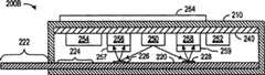
Fig. 2 A shows the cross-sectional view oftest macro 200 according to embodiments of the present invention, wherein photoelectronic device read test result.In each embodiment of the present invention,system 200 can test the medical science of any hope or environmental aspect or material, and these medical science or environmental aspect or material include, but is not limited to glucose, pregnancy, infectious disease, cholesterol, cardiac marker, drug abuse symptom, chemical pollutant orbiotoxin.System 200 compriseshousing 210,test pieces 220 andcircuit 240, andcircuit 240 compriseslight source 250,battery 252,control module 254 andphotoelectric detector
Quantum dot provides intensity to keep constant fluorescence in long-time section, and this intensity is not to reduce fast owing to the degraded that is exposed to the light time as the traditional test dyestuff.So, come the intensity measurements of self-detector bar
Fig. 2 B illustratestest macro 200B, and thistest macro 200B is similar totest macro 200, but comprises thataplhanumeric display device 264 is to output test result.For example, the LCD array of double word symbol or three-character doctrine can provide numeral output based on the measured intensity from the fluorescence of test-strips 226.Display device 264 can be in conjunction with using such as the illustrated LED of Fig. 2 A or other output system.
Fig. 2 C illustrates the test macro 200C that uses another kind of test result export technique.Particularly, test macro 200C exports electric signal with the indication test result by outside terminal 266.As described in following continuation, therefore test macro 200C can offer the test result electric signal electronic equipment (not shown) that can handle, change or transmit this test result signal.The advantage of test macro 200C is, can be removed fromcircuit 240 reducing the cost of test macro 200C such as the circuit component ofbattery 252, and electric power can be provided forcircuit 240 by outside terminal 266.
Fig. 2 D illustrates test macro 200D according to embodiments of the present invention, and this test macro 200D has adopted imaging system 255 to detect fluorescence.Imaging system 255 can comprise two-dimensional CCD or cmos imaging array or similarly can produce the photoelectronic imaging instrument of the image of electronic form (for example, the array of pixel values of expression captured images or frame).Control module 254 can be analyzed from the digital picture of imaging system 255 to determine frombar
Some advantages of test macro 200,200B, 200C and 200D comprise user acceptance test result's convenience, the consistance and the accuracy of testresult.LED lamp circuit 240 produces non-subjectivity of fluorescence intensity and/or quantitative explanation.
Adopting the test macro additional advantage of quantum dot is to test several analytes in same test-strips.Whether Fig. 3 for example illustrates the part of test macro 300 according to embodiments of the present invention, exist the plurality of target analyte to test in 300 pairs of samples of this test macro.Test macro 300 comprises test pieces 320, optoelectronic circuit 340 and interference optics 330.
Test pieces 320 can be identical with test pieces described above 220 basically, but test pieces 320 comprises the multiple demarcation material corresponding to the different target analyte.Demarcating material for every kind all is attached to the quantum dot of respective type on the corresponding target analytes.Be used for the different amount of substances points of demarcating and preferably produce fluorescence with different characteristic wavelength (for example, 525,595 and 655nm).The biological coating that has the suitable quantum dot of different fluorescence frequencies and be adapted to be incorporated into analyte selectivity immunoglobulin (Ig) can obtain with commercial system from Quantum Dot Inc..Test pieces 320 comprises test-strips 326, this test-strips 326 is processed come in conjunction with and fixedly comprise the different composite body of target analytes and each demarcation material.The cholesterol or the heart disease class testing system that in same test structure multiple analytes are tested for a plurality of factors of measurement are particularly suitable for.
Optical system 330 is optical substrate in Fig. 3, and different wave length is focused on different photoelectric detector 342,343 and 344.In one embodiment of the invention, optical system 330 comprises material such as the optical substrate for glass or plastics, and has the pattern that is made of nontransparent zone or surperficial noncontinuity, and the separation or the focusing of desirable different wave length fluorescence can be provided.But, use other method and structure, also can make diffraction optical element such as optical system 300 cheaply.
Fig. 4 shows the part with thesimilar test macro 400 of the test macro 300 of Fig. 3, buttest macro 400 comprises by refractor 431,432,433 and 434 and be positioned at theoptical system 430 that the film color filter 436,437 and 438 on the prism constitutes.Particularly,lens 431 receive and collimate from test-strips 326 emitted fluorescence when the quantum dot thatlight source 250 shines in the test-strips 326.Color filter 436 is designed to see through the light of frequency corresponding to the quantum dot of being measured byphotoelectric detector 342, and reflection is by the light offrequency light source 250 emissions or that obtained by the fluorescence of the quantum dot of other type.Have the thickness that obtains desired characteristic and a dielectric layer of refraction coefficient by stacked, can design or make up the film that can see through the light of desirable wavelength but reflect the light of other wavelength.Perhaps,color filter 436 can comprise diffraction coefficient grating filter orcoloured material.Lens 432 will focus on the photosensitive region of detectingdevice 342 through the light ofcolor filter 436, and it can also comprise that extra color filter is to select the color of desirable light extraly.
Incided on thecolor filter 437 from the light ofcolor filter 436 reflections.Colorfilter 437 is designed the light of reflection wavelength corresponding to detectingdevice 343, and sees throughunwanted wavelength.Lens 433 will focus on the optoelectronic induction zone of detectingdevice 343 from the light ofcolor filter 437 reflections.The light that sees throughcolor filter 437incides color filter 438, andcolor filter 438 is designed the light of reflection wavelength corresponding to detectingdevice 344, and sees through unwanted wavelength.The light thatlens 434 will reflect fromcolour filter film 438 focuses on the optoelectronic induction zone of detectingdevice 344.
Fig. 5 illustrates the cut-open view oftest macro 500 according to embodiments of the present invention.As shown in the figure,test macro 500 compriseshousing 510, has first slit athousing 510 1 ends, andtest pieces 520 extends through this first slit, has second slit athousing 510 relative ends,tears label 530 and extends through this second slit.Optoelectronic circuit 540 compriseslight source 250,battery 252 and other desired circuit element, and is loaded intohousing 510 inside.In addition, the optical system (not shown) can be included in thehousing 510, with the dissociated optical signal or focus the light in thecircuit 540 on one or more fluorescence detectors.
Fig. 6 illustratestest macro 600 according to embodiments of the present invention, thistest macro 600test pieces 520 of having packed in housing 610.Import in order to simplify sample,housing 610 comprises opening 612, and sample bleeds to the sample reception district oftest pieces 520 by this opening 612.The advantage ofhousing 610 has been to improve the isolation that imports after the sample test pieces 520.Then, can with the cover (not shown) cover opening 612 with further raising after importing sample duringtest macro 600 disposal to the isolation of sample.Fig. 6 also illustrates:test macro 600 can comprise tears the electricity operation thatlabel 530 begins Wireless Test Toolset 600, and comprises thatLED
Fig. 7 A illustratestest macro 700 according to another embodiment of theinvention.Test macro 700 comprisesdisposable use module 710 and reusable module 720.Disposable use module 710 comprisestest pieces 520, and thistest pieces 520 can be used by the opening on thehousing 714 712, and is such at thetest macro 600 described modes of Fig. 6 above its mode is similar to.Disposable use module 710 has the electrical interface that comprisesterminal 716, and thisterminal 716 can be inserted on thesocket 722 on the reusable module 720.Reusable module 720 can show test results onLCD display device 724 or any other appropriate users interface then.
The advantage oftest macro 700 has been to reduce the cost of disposable use module 710.Particularly, by comprise more circuit component inreusable module 720, the cost of testing repeatedly is minimized, and the sophistication of test result output be increased (for example, using alphanumeric or voice output to substitute emergency warning lamp).This such as test glucose level or nearly all diagnostic test of carrying out at the doctor's in the family, is useful especially for the test that repeats.In addition,reusable module 720 receives electric signal fromdisposable use module 710, and does not need directly to measure thetest pieces 520 that contains sample.Soreusable module 720 is not easy to be subjected to sample contamination, and sample contamination may influence the result of follow-up test.
Fig. 7 B illustrates test macro 750, usesdisposable use module 710 and exquisite more reusable module 730 as figure test macro 750.In illustrated embodiment, reusable module 730 comprises socket 732, display device 734, keyboard 736 and port 738.Socket 732socket 722 with Fig. 7 A basically is identical, and is used to admitdisposable use module 710, with transferring electric power and signal betweenmodule 710 and 730.Display device 734 can be LCD display device, touch-screen or similarly install that it is the part of reusable module 730 user interfaces, and can show any desired information that comprises test result and control information.Keyboard 736 is provided for importing the user interface of data or system control parameters.Port 738 provides to other connection such as the other system of computing machine or communication network, and for example can be the socket that is used for modem communication, USB or live wire by telephone wire or ethernet standard or the like.
Be simple relativelyreusable module 720 in thesystem 700 that adopts as Fig. 7 A, still adopt the more complicated reusable module 730 shown in Fig. 7 B, this will depend on type and the needed result who is tested usually.For example, commercial product can comprise areusable module 720 and a cover six or moredisposable use module 710, it is intended that and makesreusable module 720 only can be used limited number of times (for example, only use in the same packing disposable use module).Comparatively speaking, reusable module 730 can be designed to repeat to use in test many times, and separates sale with disposable use module 710.And the disposable use module of carrying out different tests can be compatible mutually with standardized reusable module 730, and this will allow reusable module 730 middlely at the doctor's to use, and for example be used to control and export many dissimilar tests.
Though invention has been described with reference to specific embodiment, this description only is the example of the present patent application, and should not be regarded as limiting.The feature of disclosed embodiment is carried out various modifications and makes up all will falling into by within the determined invention scope of claim.
Claims (20)
Translated fromChineseApplications Claiming Priority (2)
| Application Number | Priority Date | Filing Date | Title |
|---|---|---|---|
| US10/816,636US20050221504A1 (en) | 2004-04-01 | 2004-04-01 | Optoelectronic rapid diagnostic test system |
| US10/816,636 | 2004-04-01 |
Publications (1)
| Publication Number | Publication Date |
|---|---|
| CN1677105Atrue CN1677105A (en) | 2005-10-05 |
Family
ID=34887768
Family Applications (1)
| Application Number | Title | Priority Date | Filing Date |
|---|---|---|---|
| CNA2005100598923APendingCN1677105A (en) | 2004-04-01 | 2005-04-01 | Optoelectronic Rapid Diagnostic Test System |
Country Status (5)
| Country | Link |
|---|---|
| US (2) | US20050221504A1 (en) |
| EP (1) | EP1582598B1 (en) |
| CN (1) | CN1677105A (en) |
| CA (1) | CA2496986A1 (en) |
| DE (1) | DE602004011471T2 (en) |
Cited By (14)
| Publication number | Priority date | Publication date | Assignee | Title |
|---|---|---|---|---|
| CN101846624A (en)* | 2009-01-28 | 2010-09-29 | 住友化学株式会社 | State Estimation Method of UV Curing Resin |
| CN102495036A (en)* | 2011-12-07 | 2012-06-13 | 长春美泰科技有限公司 | On-site detector for fluorescent bleaching agent in living paper products |
| CN101592659B (en)* | 2009-02-09 | 2012-08-08 | 马义才 | System and method for quantitative detection of test strips on basis of continuous fluorescent-substance markers |
| CN101514987B (en)* | 2008-07-14 | 2012-11-21 | 马义才 | System for quantitative detection of quanta dot mark test bar and detection method thereof |
| CN104730000A (en)* | 2015-04-13 | 2015-06-24 | 大连理工大学 | Photoelectric quantitative testing device for immune chromatography reaction results |
| CN104833799A (en)* | 2014-02-07 | 2015-08-12 | 恩智浦有限公司 | Analyte detection methods and devices |
| CN105259151A (en)* | 2015-11-02 | 2016-01-20 | 深圳市锦瑞电子有限公司 | Fluorescence detection system and instrument |
| CN105264359A (en)* | 2013-05-29 | 2016-01-20 | 光电意大利有限公司 | A kit for detecting micro-rna extracted from a samlple of body fluid as well and a method for the detection thereof |
| CN109357975A (en)* | 2018-10-31 | 2019-02-19 | 福州大学 | A method to measure the effective diffusion coefficient of biomolecules |
| CN109557003A (en)* | 2019-01-23 | 2019-04-02 | 河北农业大学 | Pesticide deposition amount detection method and device and data acquisition combination device |
| CN112654858A (en)* | 2018-09-04 | 2021-04-13 | ams有限公司 | Biomarker reader |
| CN113039429A (en)* | 2018-11-14 | 2021-06-25 | 韩国巴迪泰生物科技有限公司 | Integrated immunodiagnostic fluorescence reader with multiple diagnostic functions |
| CN114413944A (en)* | 2022-03-29 | 2022-04-29 | 安徽省国盛量子科技有限公司 | Distributed optical fiber sensor based on quantum dots |
| CN115046971A (en)* | 2022-05-05 | 2022-09-13 | 中国科学院苏州生物医学工程技术研究所 | Electronic card for quickly detecting paraquat in whole blood |
Families Citing this family (85)
| Publication number | Priority date | Publication date | Assignee | Title |
|---|---|---|---|---|
| US7811231B2 (en) | 2002-12-31 | 2010-10-12 | Abbott Diabetes Care Inc. | Continuous glucose monitoring system and methods of use |
| US8066639B2 (en) | 2003-06-10 | 2011-11-29 | Abbott Diabetes Care Inc. | Glucose measuring device for use in personal area network |
| WO2005089103A2 (en) | 2004-02-17 | 2005-09-29 | Therasense, Inc. | Method and system for providing data communication in continuous glucose monitoring and management system |
| US20070143035A1 (en)* | 2005-12-19 | 2007-06-21 | Petruno Patrick T | Diagnostic test reader with disabling unit |
| US8128871B2 (en) | 2005-04-22 | 2012-03-06 | Alverix, Inc. | Lateral flow assay systems and methods |
| US7521259B2 (en)* | 2004-04-01 | 2009-04-21 | Alverix, Inc. | Assay test strips with multiple labels and reading same |
| US20070185679A1 (en)* | 2004-04-01 | 2007-08-09 | Petruno Patrick T | Indicating status of a diagnostic test system |
| US9788771B2 (en) | 2006-10-23 | 2017-10-17 | Abbott Diabetes Care Inc. | Variable speed sensor insertion devices and methods of use |
| US10041941B2 (en) | 2005-04-22 | 2018-08-07 | Alverix, Inc. | Assay test strips with multiple labels and reading same |
| US7766829B2 (en) | 2005-11-04 | 2010-08-03 | Abbott Diabetes Care Inc. | Method and system for providing basal profile modification in analyte monitoring and management systems |
| US7620438B2 (en) | 2006-03-31 | 2009-11-17 | Abbott Diabetes Care Inc. | Method and system for powering an electronic device |
| US8226891B2 (en) | 2006-03-31 | 2012-07-24 | Abbott Diabetes Care Inc. | Analyte monitoring devices and methods therefor |
| JP4695025B2 (en)* | 2006-06-19 | 2011-06-08 | 株式会社日立製作所 | Biological and chemical reaction analysis kit |
| WO2008001279A2 (en)* | 2006-06-28 | 2008-01-03 | Koninklijke Philips Electronics N.V. | Disposable assay device with removables modules and remote data transfer system |
| WO2008019695A2 (en)* | 2006-08-16 | 2008-02-21 | Thor Publishing | An interactive testing system for analysing biological samples. |
| US20080081002A1 (en)* | 2006-09-29 | 2008-04-03 | Patrick Petruno | Diagnostic assay reader having multiple power configurations |
| US7532128B2 (en)* | 2006-10-25 | 2009-05-12 | Alverix, Inc. | Position sensitive indicator detection |
| WO2008086137A1 (en)* | 2007-01-08 | 2008-07-17 | 3M Innovative Properties Company | Device for the qualification of cooking oils, and methods |
| US20080199894A1 (en) | 2007-02-15 | 2008-08-21 | Abbott Diabetes Care, Inc. | Device and method for automatic data acquisition and/or detection |
| US8930203B2 (en) | 2007-02-18 | 2015-01-06 | Abbott Diabetes Care Inc. | Multi-function analyte test device and methods therefor |
| US8732188B2 (en) | 2007-02-18 | 2014-05-20 | Abbott Diabetes Care Inc. | Method and system for providing contextual based medication dosage determination |
| JP2008241686A (en)* | 2007-02-26 | 2008-10-09 | Fujitsu Ltd | Target detection apparatus and target detection method |
| US8123686B2 (en) | 2007-03-01 | 2012-02-28 | Abbott Diabetes Care Inc. | Method and apparatus for providing rolling data in communication systems |
| WO2008130895A2 (en) | 2007-04-14 | 2008-10-30 | Abbott Diabetes Care, Inc. | Method and apparatus for providing dynamic multi-stage signal amplification in a medical device |
| US7928850B2 (en) | 2007-05-08 | 2011-04-19 | Abbott Diabetes Care Inc. | Analyte monitoring system and methods |
| US8456301B2 (en) | 2007-05-08 | 2013-06-04 | Abbott Diabetes Care Inc. | Analyte monitoring system and methods |
| US8461985B2 (en) | 2007-05-08 | 2013-06-11 | Abbott Diabetes Care Inc. | Analyte monitoring system and methods |
| US8665091B2 (en) | 2007-05-08 | 2014-03-04 | Abbott Diabetes Care Inc. | Method and device for determining elapsed sensor life |
| WO2008157820A1 (en) | 2007-06-21 | 2008-12-24 | Abbott Diabetes Care, Inc. | Health management devices and methods |
| AU2008265542B2 (en) | 2007-06-21 | 2014-07-24 | Abbott Diabetes Care Inc. | Health monitor |
| JP2011513750A (en)* | 2008-03-04 | 2011-04-28 | スリーエム イノベイティブ プロパティズ カンパニー | Method and device for monitoring the quality of frying oil |
| EP2260299A4 (en)* | 2008-03-04 | 2011-12-14 | 3M Innovative Properties Co | Monitoring of frying oil quality using combined optical interrogation methods and devices |
| US20100176279A1 (en)* | 2009-01-14 | 2010-07-15 | Alverix, Inc. | Methods and materials for detecting light released from a labeling material |
| US8103456B2 (en) | 2009-01-29 | 2012-01-24 | Abbott Diabetes Care Inc. | Method and device for early signal attenuation detection using blood glucose measurements |
| US9402544B2 (en) | 2009-02-03 | 2016-08-02 | Abbott Diabetes Care Inc. | Analyte sensor and apparatus for insertion of the sensor |
| DE102009010563A1 (en) | 2009-02-16 | 2010-08-26 | Matthias W. Engel | Device for the detection of analytes in body fluids |
| WO2010127050A1 (en) | 2009-04-28 | 2010-11-04 | Abbott Diabetes Care Inc. | Error detection in critical repeating data in a wireless sensor system |
| WO2010138856A1 (en) | 2009-05-29 | 2010-12-02 | Abbott Diabetes Care Inc. | Medical device antenna systems having external antenna configurations |
| US8993331B2 (en) | 2009-08-31 | 2015-03-31 | Abbott Diabetes Care Inc. | Analyte monitoring system and methods for managing power and noise |
| US9314195B2 (en) | 2009-08-31 | 2016-04-19 | Abbott Diabetes Care Inc. | Analyte signal processing device and methods |
| EP3001194B1 (en) | 2009-08-31 | 2019-04-17 | Abbott Diabetes Care, Inc. | Medical devices and methods |
| US9320461B2 (en) | 2009-09-29 | 2016-04-26 | Abbott Diabetes Care Inc. | Method and apparatus for providing notification function in analyte monitoring systems |
| CN102859358B (en) | 2010-01-28 | 2015-05-13 | 埃吕梅有限公司 | Sampling and testing device for the human or animal body |
| CN102985810B (en) | 2010-07-20 | 2016-04-27 | 霍夫曼-拉罗奇有限公司 | Devices for identifying analytes in body fluids |
| US8655009B2 (en) | 2010-09-15 | 2014-02-18 | Stephen L. Chen | Method and apparatus for performing color-based reaction testing of biological materials |
| US8506901B2 (en) | 2010-11-03 | 2013-08-13 | Teco Diagnostics | All-in-one specimen cup with optically readable results |
| US8486717B2 (en) | 2011-01-18 | 2013-07-16 | Symbolics, Llc | Lateral flow assays using two dimensional features |
| CN107019515B (en) | 2011-02-28 | 2021-02-26 | 雅培糖尿病护理公司 | Method of displaying sensor readings and analyte monitoring device and method of operating the same |
| WO2013066847A1 (en)* | 2011-10-31 | 2013-05-10 | Abbott Diabetes Care Inc. | Analyte sensor |
| US9069536B2 (en) | 2011-10-31 | 2015-06-30 | Abbott Diabetes Care Inc. | Electronic devices having integrated reset systems and methods thereof |
| WO2013070794A2 (en) | 2011-11-07 | 2013-05-16 | Abbott Diabetes Care Inc. | Analyte monitoring device and methods |
| US9874556B2 (en) | 2012-07-18 | 2018-01-23 | Symbolics, Llc | Lateral flow assays using two dimensional features |
| US9285323B2 (en) | 2012-08-08 | 2016-03-15 | Scanadu Incorporated | Quantifying color changes of chemical test pads induced concentrations of biological analytes under different lighting conditions |
| EP2883037B1 (en) | 2012-08-08 | 2023-06-07 | Healthy.io Ltd. | Method and apparatus for performing and quantifying color changes induced by specific concentrations of biological analytes in an automatically calibrated environment |
| US9528941B2 (en) | 2012-08-08 | 2016-12-27 | Scanadu Incorporated | Method and apparatus for determining analyte concentration by quantifying and interpreting color information captured in a continuous or periodic manner |
| US20140072959A1 (en) | 2012-09-12 | 2014-03-13 | Force Diagnostics, Inc. | Rapid tests for insurance underwriting |
| US9968306B2 (en) | 2012-09-17 | 2018-05-15 | Abbott Diabetes Care Inc. | Methods and apparatuses for providing adverse condition notification with enhanced wireless communication range in analyte monitoring systems |
| US10890590B2 (en) | 2012-09-27 | 2021-01-12 | Ellume Limited | Diagnostic devices and methods |
| US10408828B2 (en) | 2013-02-26 | 2019-09-10 | Astute Medical, Inc. | Lateral flow assay with test strip retainer |
| US9599615B2 (en) | 2013-03-13 | 2017-03-21 | Symbolics, Llc | Lateral flow assays using two dimensional test and control signal readout patterns |
| AU2013202805B2 (en) | 2013-03-14 | 2015-07-16 | Gen-Probe Incorporated | System and method for extending the capabilities of a diagnostic analyzer |
| TWI468760B (en)* | 2013-04-01 | 2015-01-11 | Delta Electronics Inc | Optical module and optical transceiver module |
| ES2974570T3 (en)* | 2013-07-12 | 2024-06-27 | Nowdiagnostics Inc | A universal rapid diagnostic test reader with trans-visual sensitivity |
| EP3036531B1 (en)* | 2013-08-20 | 2023-06-07 | Chembio Diagnostics GmbH | Device for digitally reading rapid tests |
| GB201321430D0 (en) | 2013-12-04 | 2014-01-15 | Spd Swiss Prec Diagnostics Gmbh | Assay device |
| WO2016025935A2 (en) | 2014-08-15 | 2016-02-18 | Scanadu Incorporated | Precision luxmeter methods for digital cameras to quantify colors in uncontrolled lighting environments |
| US10786229B2 (en) | 2015-01-22 | 2020-09-29 | Ellume Limited | Diagnostic devices and methods for mitigating hook effect and use thereof |
| JP2018513983A (en) | 2015-04-06 | 2018-05-31 | ブルーダイアグノスティックス・インコーポレイテッドBludiagnostics, Inc. | Test apparatus and method of use for detecting an analyte in a saliva sample |
| EP3078975B1 (en) | 2015-04-10 | 2021-06-09 | Nokia Technologies Oy | An apparatus and method for sensing |
| CN105181661A (en)* | 2015-08-11 | 2015-12-23 | 郑州安图生物工程股份有限公司 | Kit for fluorescent quantitative joint detection of Toxoplasma gondii IgG and IgM antibodies |
| GB2542802A (en)* | 2015-09-30 | 2017-04-05 | Cambridge Display Tech Ltd | Organic-based fluorescence sensor with low background signal |
| US20210278403A1 (en) | 2016-08-23 | 2021-09-09 | Qoolabs, Inc. | Lateral flow assay for assessing recombinant protein expression or reporter gene expression |
| US10852242B2 (en)* | 2016-11-30 | 2020-12-01 | Idexx Laboratories, Inc. | Lateral flow assay reader based on human perception and method relating thereto |
| US11071478B2 (en) | 2017-01-23 | 2021-07-27 | Abbott Diabetes Care Inc. | Systems, devices and methods for analyte sensor insertion |
| GB2563581A (en)* | 2017-06-16 | 2018-12-26 | Sumitomo Chemical Co | Device |
| CN108982833A (en)* | 2018-04-17 | 2018-12-11 | 山东安博仪器股份有限公司 | A kind of Test paper and detection method of malachite green |
| EP3772646B1 (en)* | 2019-08-06 | 2024-04-24 | ams-OSRAM AG | Test strip, monitoring device and method for fabricating a test strip |
| CA3160797A1 (en) | 2019-11-13 | 2021-05-20 | Scanwell Health, Inc. | Diagnostic test kits for sample preparation and analysis |
| WO2021216958A1 (en)* | 2020-04-24 | 2021-10-28 | The Regents Of The University Of California | Devices and methods for two-dimension (2d)-based protein and particle detection |
| CA3188510A1 (en) | 2020-08-31 | 2022-03-03 | Vivek S. RAO | Systems, devices, and methods for analyte sensor insertion |
| WO2022060415A1 (en) | 2020-09-17 | 2022-03-24 | Scanwell Health, Inc. | Diagnostic test kits and methods of analyzing the same |
| USD970033S1 (en) | 2020-10-23 | 2022-11-15 | Becton, Dickinson And Company | Cartridge imaging background device |
| US11988596B2 (en) | 2020-10-23 | 2024-05-21 | Becton, Dickinson And Company | Systems and methods for imaging and image-based analysis of test devices |
| WO2022106537A1 (en)* | 2020-11-20 | 2022-05-27 | Ams-Osram Ag | Test strip cassette, monitoring device and method for fabricating a test strip cassette |
| CN116917714A (en)* | 2021-03-05 | 2023-10-20 | 3M创新有限公司 | Optical stack, optical system, optical detection system, and optical imaging system |
Family Cites Families (43)
| Publication number | Priority date | Publication date | Assignee | Title |
|---|---|---|---|---|
| US4935346A (en)* | 1986-08-13 | 1990-06-19 | Lifescan, Inc. | Minimum procedure system for the determination of analytes |
| US5132097A (en)* | 1987-02-11 | 1992-07-21 | G.D. Research | Apparatus for analysis of specific binding complexes |
| US4902278A (en)* | 1987-02-18 | 1990-02-20 | Ivac Corporation | Fluid delivery micropump |
| ES2150428T3 (en)* | 1987-04-27 | 2000-12-01 | Unilever Nv | SPECIFIC UNION TESTS. |
| DE59207589D1 (en)* | 1991-04-26 | 1997-01-09 | Scherrer Inst Paul | METHOD AND DEVICE FOR DETERMINING A MEASURED VALUE BY MEANS OF AN INTEGRATED-OPTICAL SENSOR MODULE |
| EP0537431B1 (en)* | 1991-10-14 | 1997-05-28 | Mars, Incorporated | Device for the optical recognition of documents |
| US5217832A (en)* | 1992-01-23 | 1993-06-08 | The Walt Disney Company | Permanent color transparencies on single substrates and methods for making the same |
| US5371687A (en)* | 1992-11-20 | 1994-12-06 | Boehringer Mannheim Corporation | Glucose test data acquisition and management system |
| WO1995006240A1 (en)* | 1993-08-24 | 1995-03-02 | Metrika Laboratories, Inc. | Novel disposable electronic assay device |
| US5837546A (en)* | 1993-08-24 | 1998-11-17 | Metrika, Inc. | Electronic assay device and method |
| WO1997006439A1 (en)* | 1995-08-09 | 1997-02-20 | Quidel Corporation | Test strip and method for one step lateral flow assay |
| US5723294A (en)* | 1996-03-05 | 1998-03-03 | Gull Laboratories | Methods for detection and discrimination of multiple analytes using fluorescent technology |
| US5961451A (en)* | 1997-04-07 | 1999-10-05 | Motorola, Inc. | Noninvasive apparatus having a retaining member to retain a removable biosensor |
| US6046051A (en)* | 1997-06-27 | 2000-04-04 | Hemosense, Inc. | Method and device for measuring blood coagulation or lysis by viscosity changes |
| US6561643B1 (en)* | 1997-06-30 | 2003-05-13 | Hewlett-Packard Co. | Advanced media determination system for inkjet printing |
| US6585341B1 (en)* | 1997-06-30 | 2003-07-01 | Hewlett-Packard Company | Back-branding media determination system for inkjet printing |
| WO2000006990A2 (en)* | 1998-07-27 | 2000-02-10 | Ljl Biosystems, Inc. | Apparatus and methods for time-resolved spectroscopic measurements |
| US6394952B1 (en)* | 1998-02-03 | 2002-05-28 | Adeza Biomedical Corporation | Point of care diagnostic systems |
| US20010035990A1 (en)* | 1998-04-13 | 2001-11-01 | Fai H Mok | Multiplexed hologram copying system and method |
| JP3969467B2 (en)* | 1998-06-17 | 2007-09-05 | 富士通株式会社 | Network system, transmission / reception method, transmission device, reception device, and recording medium |
| US6136610A (en)* | 1998-11-23 | 2000-10-24 | Praxsys Biosystems, Inc. | Method and apparatus for performing a lateral flow assay |
| US6217744B1 (en)* | 1998-12-18 | 2001-04-17 | Peter Crosby | Devices for testing fluid |
| US6300141B1 (en)* | 1999-03-02 | 2001-10-09 | Helix Biopharma Corporation | Card-based biosensor device |
| JP2002544488A (en)* | 1999-05-07 | 2002-12-24 | クアンタム ドット コーポレイション | Methods for detecting analytes using semiconductor nanocrystals |
| US20020004246A1 (en)* | 2000-02-07 | 2002-01-10 | Daniels Robert H. | Immunochromatographic methods for detecting an analyte in a sample which employ semiconductor nanocrystals as detectable labels |
| US6671428B1 (en)* | 2000-12-01 | 2003-12-30 | Bayspec, Inc. | Wavelength selective optical cross switch and optical add/drop multiplexer using volume phase grating and array of micro electro mechanical mirrors |
| US6572745B2 (en)* | 2001-03-23 | 2003-06-03 | Virotek, L.L.C. | Electrochemical sensor and method thereof |
| US20020176927A1 (en)* | 2001-03-29 | 2002-11-28 | Kodas Toivo T. | Combinatorial synthesis of material systems |
| US20020143844A1 (en)* | 2001-03-29 | 2002-10-03 | Wen-Sung Tsai | Computer system with two operating systems |
| US6379622B1 (en)* | 2001-04-11 | 2002-04-30 | Motorola, Inc. | Sensor incorporating a quantum dot as a reference |
| DK1432786T3 (en)* | 2001-09-06 | 2009-10-26 | Rapid Micro Biosystems Inc | Rapid detection of replicated cells |
| US7635588B2 (en)* | 2001-11-29 | 2009-12-22 | Applied Biosystems, Llc | Apparatus and method for differentiating multiple fluorescence signals by excitation wavelength |
| US8367013B2 (en)* | 2001-12-24 | 2013-02-05 | Kimberly-Clark Worldwide, Inc. | Reading device, method, and system for conducting lateral flow assays |
| US20030119203A1 (en)* | 2001-12-24 | 2003-06-26 | Kimberly-Clark Worldwide, Inc. | Lateral flow assay devices and methods for conducting assays |
| US6717967B2 (en)* | 2002-03-18 | 2004-04-06 | Dicos Technologies Inc. | Absolutely calibrated periodic filters and sources |
| US20030207454A1 (en)* | 2002-05-01 | 2003-11-06 | Eyster Curt R. | Devices and methods for analyte concentration determination |
| ATE537438T1 (en)* | 2002-05-17 | 2011-12-15 | Life Technologies Corp | DEVICE AND METHOD FOR DISTINGUISHING SEVERAL FLUORESCENCE SIGNALS BASED ON THEIR EXCITATION WAVELENGTH |
| US6750963B2 (en)* | 2002-05-21 | 2004-06-15 | Agilent Technologies, Inc. | Imaging systems for signals on a surface |
| US6987259B2 (en)* | 2002-05-30 | 2006-01-17 | Dmetrix, Inc. | Imaging system with an integrated source and detector array |
| EP1516172A1 (en)* | 2002-06-27 | 2005-03-23 | Unipath Limited | Assay reader |
| US6875185B2 (en)* | 2002-07-29 | 2005-04-05 | Branan Medical Corporation | Integrated confirmation sample in a body fluid test device and method of using |
| US7285424B2 (en)* | 2002-08-27 | 2007-10-23 | Kimberly-Clark Worldwide, Inc. | Membrane-based assay devices |
| US7220597B2 (en)* | 2003-01-30 | 2007-05-22 | Zin Benedict L | Assay test device and method of making same |
- 2004
- 2004-04-01USUS10/816,636patent/US20050221504A1/ennot_activeAbandoned
- 2004-12-20EPEP04030193Apatent/EP1582598B1/ennot_activeExpired - Lifetime
- 2004-12-20DEDE602004011471Tpatent/DE602004011471T2/ennot_activeExpired - Lifetime
- 2005
- 2005-01-26USUS11/044,394patent/US20050221505A1/ennot_activeAbandoned
- 2005-02-14CACA002496986Apatent/CA2496986A1/ennot_activeAbandoned
- 2005-04-01CNCNA2005100598923Apatent/CN1677105A/enactivePending
Cited By (14)
| Publication number | Priority date | Publication date | Assignee | Title |
|---|---|---|---|---|
| CN101514987B (en)* | 2008-07-14 | 2012-11-21 | 马义才 | System for quantitative detection of quanta dot mark test bar and detection method thereof |
| CN101846624A (en)* | 2009-01-28 | 2010-09-29 | 住友化学株式会社 | State Estimation Method of UV Curing Resin |
| CN101592659B (en)* | 2009-02-09 | 2012-08-08 | 马义才 | System and method for quantitative detection of test strips on basis of continuous fluorescent-substance markers |
| CN102495036A (en)* | 2011-12-07 | 2012-06-13 | 长春美泰科技有限公司 | On-site detector for fluorescent bleaching agent in living paper products |
| CN105264359A (en)* | 2013-05-29 | 2016-01-20 | 光电意大利有限公司 | A kit for detecting micro-rna extracted from a samlple of body fluid as well and a method for the detection thereof |
| CN104833799A (en)* | 2014-02-07 | 2015-08-12 | 恩智浦有限公司 | Analyte detection methods and devices |
| CN104730000A (en)* | 2015-04-13 | 2015-06-24 | 大连理工大学 | Photoelectric quantitative testing device for immune chromatography reaction results |
| CN105259151A (en)* | 2015-11-02 | 2016-01-20 | 深圳市锦瑞电子有限公司 | Fluorescence detection system and instrument |
| CN112654858A (en)* | 2018-09-04 | 2021-04-13 | ams有限公司 | Biomarker reader |
| CN109357975A (en)* | 2018-10-31 | 2019-02-19 | 福州大学 | A method to measure the effective diffusion coefficient of biomolecules |
| CN113039429A (en)* | 2018-11-14 | 2021-06-25 | 韩国巴迪泰生物科技有限公司 | Integrated immunodiagnostic fluorescence reader with multiple diagnostic functions |
| CN109557003A (en)* | 2019-01-23 | 2019-04-02 | 河北农业大学 | Pesticide deposition amount detection method and device and data acquisition combination device |
| CN114413944A (en)* | 2022-03-29 | 2022-04-29 | 安徽省国盛量子科技有限公司 | Distributed optical fiber sensor based on quantum dots |
| CN115046971A (en)* | 2022-05-05 | 2022-09-13 | 中国科学院苏州生物医学工程技术研究所 | Electronic card for quickly detecting paraquat in whole blood |
Also Published As
| Publication number | Publication date |
|---|---|
| EP1582598A1 (en) | 2005-10-05 |
| DE602004011471T2 (en) | 2009-01-15 |
| US20050221504A1 (en) | 2005-10-06 |
| US20050221505A1 (en) | 2005-10-06 |
| DE602004011471D1 (en) | 2008-03-13 |
| EP1582598B1 (en) | 2008-01-23 |
| CA2496986A1 (en) | 2005-10-01 |
Similar Documents
| Publication | Publication Date | Title |
|---|---|---|
| CN1677105A (en) | Optoelectronic Rapid Diagnostic Test System | |
| EP1634062B1 (en) | Readhead for optical inspection apparatus | |
| JP5203453B2 (en) | Reaction vessel with integrated optical and fluid control elements | |
| US20100201988A1 (en) | Transmitting/Reflecting Emanating Light With Time Variation | |
| US7768645B2 (en) | Miniature optical readhead and colorimeter for analysis media | |
| JP2019529920A (en) | Analytical test equipment | |
| WO2010059537A1 (en) | Polarized optics for optical diagnostic device | |
| CN1916628A (en) | Apparatus and method for discriminating among lateral flow assay test indicators | |
| WO2005054826A1 (en) | Optical analyzing unit and optical analyzing device | |
| US7339673B2 (en) | Miniature optical readhead for optical diagnostic device | |
| EP2990779B1 (en) | Device for detecting analyzed object in specimen and method therefor | |
| AU738290B2 (en) | Method and apparatus for determining characteristics of a sample in the presence of ambient light | |
| US20220404354A1 (en) | Real-time, point of care diagnostic and method of use thereof | |
| KR101514694B1 (en) | Devices and Methods for Detecting Analytes in Samples | |
| US20060128034A1 (en) | Diagnostic test using gated measurement of fluorescence from quantum dots | |
| US7264971B2 (en) | Read-head for optical diagnostic device | |
| US20230003722A1 (en) | Methods and compositions for lateral flow analyte assays | |
| CN210166298U (en) | Information acquisition device for dry chemical analysis and immunological analysis | |
| Lee et al. | Novel optical absorbance-based multi-analytes detection module using a tri-chromatic LED, PDs and plastic optical fibers and its application to a palm-sized urine test strip reader | |
| KR20250064335A (en) | Apparatus and system for analyzing lateral flow assay | |
| GB2602268A (en) | Time-resolved fluorescence reader and method | |
| GB2609419A (en) | Lateral flow test |
Legal Events
| Date | Code | Title | Description |
|---|---|---|---|
| C06 | Publication | ||
| PB01 | Publication | ||
| C41 | Transfer of patent application or patent right or utility model | ||
| TA01 | Transfer of patent application right | Effective date of registration:20061201 Address after:Singapore Singapore Applicant after:Avago Technologies General IP (Singapore) Pte. Ltd. Address before:American California Applicant before:Anjelen Sci. & Tech. Inc. | |
| C10 | Entry into substantive examination | ||
| SE01 | Entry into force of request for substantive examination | ||
| ASS | Succession or assignment of patent right | Owner name:EVERIX CO., LTD. Free format text:FORMER OWNER: AVAGO TECHNOLOGIES GENERAL IP Effective date:20081010 | |
| C41 | Transfer of patent application or patent right or utility model | ||
| TA01 | Transfer of patent application right | Effective date of registration:20081010 Address after:Delaware Applicant after:Agilent Technologies Inc. Address before:Singapore Singapore Applicant before:Avago Technologies General IP (Singapore) Pte. Ltd. | |
| C02 | Deemed withdrawal of patent application after publication (patent law 2001) | ||
| WD01 | Invention patent application deemed withdrawn after publication | Open date:20051005 |