CN1676355A - strut suspension - Google Patents
strut suspensionDownload PDFInfo
- Publication number
- CN1676355A CN1676355ACN200510059895.7ACN200510059895ACN1676355ACN 1676355 ACN1676355 ACN 1676355ACN 200510059895 ACN200510059895 ACN 200510059895ACN 1676355 ACN1676355 ACN 1676355A
- Authority
- CN
- China
- Prior art keywords
- shaft
- spring
- pillar
- axis
- type suspension
- Prior art date
- Legal status (The legal status is an assumption and is not a legal conclusion. Google has not performed a legal analysis and makes no representation as to the accuracy of the status listed.)
- Granted
Links
Images
Classifications
- B—PERFORMING OPERATIONS; TRANSPORTING
- B60—VEHICLES IN GENERAL
- B60G—VEHICLE SUSPENSION ARRANGEMENTS
- B60G15/00—Resilient suspensions characterised by arrangement, location or type of combined spring and vibration damper, e.g. telescopic type
- B60G15/02—Resilient suspensions characterised by arrangement, location or type of combined spring and vibration damper, e.g. telescopic type having mechanical spring
- B60G15/06—Resilient suspensions characterised by arrangement, location or type of combined spring and vibration damper, e.g. telescopic type having mechanical spring and fluid damper
- B60G15/067—Resilient suspensions characterised by arrangement, location or type of combined spring and vibration damper, e.g. telescopic type having mechanical spring and fluid damper characterised by the mounting on the vehicle body or chassis of the spring and damper unit
- B60G15/068—Resilient suspensions characterised by arrangement, location or type of combined spring and vibration damper, e.g. telescopic type having mechanical spring and fluid damper characterised by the mounting on the vehicle body or chassis of the spring and damper unit specially adapted for MacPherson strut-type suspension
- B—PERFORMING OPERATIONS; TRANSPORTING
- B60—VEHICLES IN GENERAL
- B60G—VEHICLE SUSPENSION ARRANGEMENTS
- B60G15/00—Resilient suspensions characterised by arrangement, location or type of combined spring and vibration damper, e.g. telescopic type
- B60G15/02—Resilient suspensions characterised by arrangement, location or type of combined spring and vibration damper, e.g. telescopic type having mechanical spring
- B60G15/06—Resilient suspensions characterised by arrangement, location or type of combined spring and vibration damper, e.g. telescopic type having mechanical spring and fluid damper
- B60G15/062—Resilient suspensions characterised by arrangement, location or type of combined spring and vibration damper, e.g. telescopic type having mechanical spring and fluid damper the spring being arranged around the damper
- B60G15/063—Resilient suspensions characterised by arrangement, location or type of combined spring and vibration damper, e.g. telescopic type having mechanical spring and fluid damper the spring being arranged around the damper characterised by the mounting of the spring on the damper
- B—PERFORMING OPERATIONS; TRANSPORTING
- B60—VEHICLES IN GENERAL
- B60G—VEHICLE SUSPENSION ARRANGEMENTS
- B60G15/00—Resilient suspensions characterised by arrangement, location or type of combined spring and vibration damper, e.g. telescopic type
- B60G15/02—Resilient suspensions characterised by arrangement, location or type of combined spring and vibration damper, e.g. telescopic type having mechanical spring
- B60G15/06—Resilient suspensions characterised by arrangement, location or type of combined spring and vibration damper, e.g. telescopic type having mechanical spring and fluid damper
- B60G15/07—Resilient suspensions characterised by arrangement, location or type of combined spring and vibration damper, e.g. telescopic type having mechanical spring and fluid damper the damper being connected to the stub axle and the spring being arranged around the damper
- B—PERFORMING OPERATIONS; TRANSPORTING
- B60—VEHICLES IN GENERAL
- B60G—VEHICLE SUSPENSION ARRANGEMENTS
- B60G17/00—Resilient suspensions having means for adjusting the spring or vibration-damper characteristics, for regulating the distance between a supporting surface and a sprung part of vehicle or for locking suspension during use to meet varying vehicular or surface conditions, e.g. due to speed or load
- B60G17/02—Spring characteristics, e.g. mechanical springs and mechanical adjusting means
- B60G17/021—Spring characteristics, e.g. mechanical springs and mechanical adjusting means the mechanical spring being a coil spring
- B—PERFORMING OPERATIONS; TRANSPORTING
- B60—VEHICLES IN GENERAL
- B60G—VEHICLE SUSPENSION ARRANGEMENTS
- B60G2200/00—Indexing codes relating to suspension types
- B60G2200/10—Independent suspensions
- B60G2200/14—Independent suspensions with lateral arms
- B60G2200/142—Independent suspensions with lateral arms with a single lateral arm, e.g. MacPherson type
- B—PERFORMING OPERATIONS; TRANSPORTING
- B60—VEHICLES IN GENERAL
- B60G—VEHICLE SUSPENSION ARRANGEMENTS
- B60G2200/00—Indexing codes relating to suspension types
- B60G2200/10—Independent suspensions
- B60G2200/17—Independent suspensions with a strut contributing to the suspension geometry by being articulated onto the wheel support
- B—PERFORMING OPERATIONS; TRANSPORTING
- B60—VEHICLES IN GENERAL
- B60G—VEHICLE SUSPENSION ARRANGEMENTS
- B60G2200/00—Indexing codes relating to suspension types
- B60G2200/40—Indexing codes relating to the wheels in the suspensions
- B60G2200/46—Indexing codes relating to the wheels in the suspensions camber angle
- B—PERFORMING OPERATIONS; TRANSPORTING
- B60—VEHICLES IN GENERAL
- B60G—VEHICLE SUSPENSION ARRANGEMENTS
- B60G2202/00—Indexing codes relating to the type of spring, damper or actuator
- B60G2202/30—Spring/Damper and/or actuator Units
- B60G2202/31—Spring/Damper and/or actuator Units with the spring arranged around the damper, e.g. MacPherson strut
- B60G2202/312—The spring being a wound spring
- B—PERFORMING OPERATIONS; TRANSPORTING
- B60—VEHICLES IN GENERAL
- B60G—VEHICLE SUSPENSION ARRANGEMENTS
- B60G2204/00—Indexing codes related to suspensions per se or to auxiliary parts
- B60G2204/10—Mounting of suspension elements
- B60G2204/12—Mounting of springs or dampers
- B60G2204/124—Mounting of coil springs
- B60G2204/1242—Mounting of coil springs on a damper, e.g. MacPerson strut
- B—PERFORMING OPERATIONS; TRANSPORTING
- B60—VEHICLES IN GENERAL
- B60G—VEHICLE SUSPENSION ARRANGEMENTS
- B60G2204/00—Indexing codes related to suspensions per se or to auxiliary parts
- B60G2204/10—Mounting of suspension elements
- B60G2204/12—Mounting of springs or dampers
- B60G2204/128—Damper mount on vehicle body or chassis
- B—PERFORMING OPERATIONS; TRANSPORTING
- B60—VEHICLES IN GENERAL
- B60G—VEHICLE SUSPENSION ARRANGEMENTS
- B60G2204/00—Indexing codes related to suspensions per se or to auxiliary parts
- B60G2204/40—Auxiliary suspension parts; Adjustment of suspensions
- B60G2204/43—Fittings, brackets or knuckles
- B—PERFORMING OPERATIONS; TRANSPORTING
- B60—VEHICLES IN GENERAL
- B60G—VEHICLE SUSPENSION ARRANGEMENTS
- B60G2204/00—Indexing codes related to suspensions per se or to auxiliary parts
- B60G2204/40—Auxiliary suspension parts; Adjustment of suspensions
- B60G2204/44—Centering or positioning means
- B—PERFORMING OPERATIONS; TRANSPORTING
- B60—VEHICLES IN GENERAL
- B60G—VEHICLE SUSPENSION ARRANGEMENTS
- B60G2204/00—Indexing codes related to suspensions per se or to auxiliary parts
- B60G2204/61—Adjustable during maintenance
- B—PERFORMING OPERATIONS; TRANSPORTING
- B60—VEHICLES IN GENERAL
- B60G—VEHICLE SUSPENSION ARRANGEMENTS
- B60G2206/00—Indexing codes related to the manufacturing of suspensions: constructional features, the materials used, procedures or tools
- B60G2206/01—Constructional features of suspension elements, e.g. arms, dampers, springs
- B60G2206/40—Constructional features of dampers and/or springs
- B60G2206/42—Springs
- B60G2206/426—Coil springs having a particular shape, e.g. curved axis, pig-tail end coils
Landscapes
- Engineering & Computer Science (AREA)
- Mechanical Engineering (AREA)
- Vehicle Body Suspensions (AREA)
- Fluid-Damping Devices (AREA)
- Springs (AREA)
Abstract
Translated fromChinese
Description
Translated fromChinese技术领域technical field
本发明涉及螺旋弹簧的螺旋中心轴相对于中心销轴处于扭曲关系的支柱式悬挂。The present invention relates to strut suspensions in which the helical central axis of the coil spring is in a twisted relationship with respect to the central pin axis.
背景技术Background technique
以往,提出有如下的支柱式悬挂(例如,参照日本专利文献特开平11-48728号公报),其将螺旋弹簧的螺旋中心轴(轴线)设定为相对于中心销轴处于扭曲关系,并使得围绕中心销轴产生内倾(toe-in)方向的力矩,从而谋求车辆的响应性、稳定性、直线前进性的提高。Conventionally, a strut type suspension has been proposed (for example, refer to Japanese Patent Application Laid-Open No. 11-48728), which sets the coil center axis (axis) of the coil spring in a twisted relationship with respect to the center pin axis, and makes the Moment in the toe-in direction is generated around the center pin axis, thereby improving responsiveness, stability, and straightness of the vehicle.
然而,在上述那种支柱式悬挂中,不管螺旋弹簧的螺旋中心轴与中心销轴之间的扭曲关系的设定方法如何,在悬挂上下运动(stroke)时,螺旋弹簧的上弹簧座发生旋转时,螺旋中心轴相对于中心销轴的扭曲关系可能会发生变化,并且力臂长可能发生变化。此时,当在左右轮上设定了相同卷绕方向的螺旋弹簧时,在左右轮同相运动时力臂长会产生左右差,左右轮都会在同一方向(例如右切方向)上产生转向力矩,从而产生车辆滑移的问题。However, in the above-mentioned strut type suspension, regardless of the setting method of the torsion relationship between the coil center axis of the coil spring and the center pin axis, when the suspension moves up and down (stroke), the upper spring seat of the coil spring rotates , the torsion relationship of the screw center axis relative to the center pin axis may change, and the moment arm length may change. At this time, when the coil springs with the same winding direction are set on the left and right wheels, there will be a left-right difference in the length of the moment arm when the left and right wheels move in the same phase, and the left and right wheels will generate steering torque in the same direction (such as the right tangential direction) , resulting in the problem of vehicle slippage.
发明内容Contents of the invention
因此,本发明的目的在于提供一种可以实质性地消除作为上述车辆滑移问题的原因的力臂长的变化,或者降低左右轮同相运动时的力臂长的左右差的支柱式悬挂。Therefore, it is an object of the present invention to provide a strut suspension that can substantially eliminate the variation in moment arm length that is the cause of the above-mentioned vehicle slipping problem, or reduce the left-right difference in moment arm length when the left and right wheels move in the same phase.
为了解决上述问题,根据本发明的一个方式可以提供一种支柱式悬挂,所述支柱式悬挂包括:支柱,其上端支承于车体,下端支承于悬臂;上侧弹簧座,其可旋转地支承于支柱上;下侧弹簧座,其固定于支柱上;和螺旋弹簧,其卷绕支柱而配置于上侧弹簧座与下侧弹簧座之间;并且螺旋弹簧的螺旋中心轴相对于中心销轴处于扭曲关系中,所述支柱式悬挂的特征在于,其中,In order to solve the above problems, according to one aspect of the present invention, a strut type suspension can be provided. The strut type suspension includes: a strut whose upper end is supported on the vehicle body and whose lower end is supported by a cantilever; on the pillar; the lower spring seat, which is fixed on the pillar; and the coil spring, which is wound around the pillar and arranged between the upper spring seat and the lower spring seat; and the helical central axis of the coil spring is relative to the center pin In a twisted relationship, the strut suspension is characterized in that,
上侧弹簧座的旋转中心轴与螺旋弹簧的螺旋中心轴一致。The rotation central axis of the upper spring seat coincides with the helical central axis of the coil spring.
根据本方式,可以实质性地消除悬挂的上下运动时的力臂长的变化。According to this aspect, it is possible to substantially eliminate the change in the moment arm length when the suspension moves up and down.
此外,根据本发明的另一个方式可以提供一种支柱式悬挂,所述支柱式悬挂包括:支柱,其上端支承于车体,下端支承于悬臂;上侧弹簧座,其可旋转地支承于支柱上;下侧弹簧座,其固定于支柱上;和螺旋弹簧,其卷绕支柱而配置于上侧弹簧座与下侧弹簧座之间;并且螺旋弹簧的螺旋中心轴相对于中心销轴处于扭曲关系中,所述支柱式悬挂的特征在于,其中,In addition, according to another aspect of the present invention, a strut type suspension can be provided. The strut type suspension includes: a strut whose upper end is supported by the vehicle body and whose lower end is supported by a cantilever; an upper spring seat rotatably supported by the strut the upper side spring seat, which is fixed on the pillar; and the coil spring, which is wound around the pillar and arranged between the upper spring seat and the lower spring seat; and the helical center axis of the coil spring is twisted relative to the center pin In relation, the strut suspension is characterized in that, wherein,
在沿支柱的轴向从上方看到的俯视图中,螺旋弹簧的下侧的轴中心相对于支柱轴位于车辆前侧,并且,连接螺旋弹簧的上侧的轴中心与支柱轴的直线位于:相对于连接螺旋弹簧的下侧的轴中心与支柱轴的直线绕着支柱轴在车辆外侧方向上旋转了40度~50度的方向上。In a plan view seen from above in the axial direction of the strut, the shaft center of the lower side of the coil spring is located on the front side of the vehicle with respect to the strut shaft, and the line connecting the shaft center of the upper side of the coil spring and the strut shaft is located opposite to The straight line connecting the shaft center on the lower side of the coil spring and the strut shaft is in a direction rotated by 40° to 50° in the vehicle outer direction around the strut shaft.
根据本方式,可以降低左右轮同相运动时的力臂长的左右差。According to this aspect, it is possible to reduce the left-right difference in moment arm length when the left and right wheels move in the same phase.
在任何一个方式中,都可以相对于左右轮而左右对称地构成,并且螺旋弹簧的卷绕方向左右相同。此外,还可以螺旋弹簧的螺旋中心轴与中心销轴处于绕着中心销轴产生内倾方向的力矩的扭曲关系中。此外,在沿支柱的轴向从上方看到的俯视图中,连接螺旋弹簧的下侧的轴中心与支柱轴的直线实质上与车辆的前后方向一致也可以。In either form, the configuration may be bilaterally symmetrical with respect to the left and right wheels, and the winding directions of the coil springs may be the same on the left and right. In addition, it is also possible that the helical central axis of the coil spring and the central pin are in a twisting relationship around the central pin to generate a moment in an inward direction. In addition, in a plan view seen from above along the axial direction of the strut, a straight line connecting the lower shaft center of the coil spring and the strut axis may substantially coincide with the front-rear direction of the vehicle.
根据本发明,可以获得一种支柱式悬挂,其实质性地消除了悬挂运动时的力臂长的变化,或者,降低了左右轮同相运动时的力臂长的左右差。According to the present invention, a strut suspension can be obtained, which substantially eliminates the variation of the moment arm length when the suspension moves, or reduces the left-right difference of the moment arm length when the left and right wheels move in the same phase.
附图说明Description of drawings
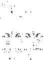
图1(A)、图1(B)及图1(C)是表示本发明的支柱式悬挂的第一Fig. 1 (A), Fig. 1 (B) and Fig. 1 (C) are the first ones that represent strut type suspension of the present invention
实施例的三视图;Three views of the embodiment;
图2(A)、图2(B)、图2(C)及图2(D)是表示第一实施例的支柱式悬挂的特性的图表;Fig. 2 (A), Fig. 2 (B), Fig. 2 (C) and Fig. 2 (D) are graphs representing the characteristics of the strut type suspension of the first embodiment;
图3(A)、图3(B)及图3(C)是表示本发明的支柱式悬挂的第二实施例的三视图。3(A), FIG. 3(B) and FIG. 3(C) are three views showing the second embodiment of the strut type suspension of the present invention.
具体实施方式Detailed ways
下面,参照附图,对用于实施本发明的最佳方式进行说明。本发明可应用于麦克斯杆式(McPherson strut)悬挂(由作为悬架连接的一部分而使用的减震器和传动连杆构成的悬挂方式)。Hereinafter, the best mode for carrying out the present invention will be described with reference to the drawings. The invention is applicable to McPherson strut suspensions (suspensions consisting of shock absorbers and transmission links used as part of the suspension connection).
图1(A)、图1(B)及图1(C)以三视图示出了本发明的支柱式悬挂的第一实施例,其中,图1(A)是在支柱的轴向上从上方看到的俯视图(图中左侧为车辆前侧),图1(B)是从车辆内侧看到的侧视图,图1(C)是从车辆后方看到的后视图。Fig. 1 (A), Fig. 1 (B) and Fig. 1 (C) show the first embodiment of the strut suspension of the present invention in three views, wherein, Fig. 1 (A) is in the axial direction of the strut The top view seen from above (the left side of the figure is the front side of the vehicle), Fig. 1(B) is a side view seen from the inside of the vehicle, and Fig. 1(C) is a rear view seen from the rear of the vehicle.
特别地,参照图1(B),上支撑10设置于发动机舱内的悬挂支架上,从而将悬挂车轮的支柱总成70的上侧支承在车体上。在上支撑10上,通过橡胶等支承减震器30的活塞杆32的上端部。减震器30的活塞缸34的下端通过悬臂或者铰链等与车轮连接。In particular, referring to FIG. 1(B), the upper support 10 is disposed on the suspension bracket in the engine compartment so as to support the upper side of the
在上支撑10的下侧,通过轴承12可旋转地支承上侧的上弹簧座42a,在减震器30的活塞缸34固定着下侧的下弹簧座42b。在上下弹簧座42a、42b之间,环绕减震器30设置螺旋弹簧40。螺旋弹簧40可以是配有直线的螺旋中心轴的任何一种螺旋弹簧,例如,可以是上端直径与下端直径相同的样式,也可以是上端直径与下端直径不同的所谓大尾部样式或者中间部分膨胀的桶形样式。众所周知,减震器30作为连接的一部分而支承上下方向的载荷,并具有在车轮上下运动(跳动或者回弹)时妨碍螺旋弹簧40的弹簧弹性的功能。On the lower side of the upper support 10 , an upper
此外,虽然在图1中为了清楚而没有示出,但支柱总成70可以包括其他通常的结构要素,例如,可以在减震器30的外周部设置防尘罩,在减震器30的活塞杆32上设置限制活塞缸34向上移动的限位止动器。In addition, although not shown in FIG. 1 for the sake of clarity, the
接着对本实施例的特征结构进行说明。减震器30的吸震轴(支柱轴)与上弹簧座42a的旋转轴(轴承12的旋转中心)一致(螺旋中心轴与轴承12的旋转中心不一致)。此外,在减震器30的吸震轴与轴承12的旋转中心一致的结构中,在轴承12与减震器30的活塞杆32之间可以容易地确保必要的间隙。此外,在侧视图(图1(B))中,吸震轴(=轴承12的旋转轴)如通常那样与中心销轴KP大体一致。在后视图(图1(C))中,中心销轴KP如通常那样,其上侧倾向车辆内侧。Next, the characteristic structure of this embodiment will be described. The shock-absorbing axis (pillar axis) of the
在侧视图(图1(B))中,螺旋弹簧40的螺旋中心轴被设定得比吸震轴更靠向车辆前侧,且与吸震轴大体平行。在后视图(图1(C))中,螺旋中心轴的上侧倾向车辆外侧。因此,在沿支柱的轴向从上方看到的俯视图(图1(A))中,螺旋中心轴的上侧的轴中心C1(上弹簧座42a上的螺旋弹簧40的轴中心)相对于吸震轴被配置在车辆前侧,且在车辆内外方向上的大致同一位置上。In a side view ( FIG. 1(B) ), the coil central axis of the
在本实施例中,在沿支柱的轴向从上方看到的俯视图(图1(A))中,螺旋上侧轴中心C1被设定在相对于螺旋下侧轴中心C2,绕着吸震轴在车辆外侧方向的旋转方向上大约偏移45度的位置(即,连接螺旋上侧轴中心C1和吸震轴的直线Y,与连接螺旋弹簧下侧的轴中心C2和吸震轴的直线T成45度)。再换句话说,当简单地将图1(A)的L方向设为车辆后方向,将W方向设为车辆外方向时,螺旋上侧轴中心C1相对于吸震轴位于向车辆外方向倾斜45度的前方,螺旋下侧轴中心C2相对于吸震轴位于车辆前方。但实际上,吸震轴与铅垂方向平行的情况几乎没有,因此,L方向并不是与车辆前后轴完全一致,同样地,W方向也不是与车辆横向完全一致。In the present embodiment, in a plan view ( FIG. 1(A) ) seen from above in the axial direction of the strut, the helical upper shaft center C1 is set relative to the helical lower shaft center C2 around the shock-absorbing axis. The position shifted by about 45 degrees in the rotation direction of the vehicle outer direction (that is, the straight line Y connecting the upper side shaft center C1 of the spiral and the shock-absorbing shaft is 45 degrees from the straight line T connecting the shaft center C2 on the lower side of the coil spring and the shock-absorbing shaft. Spend). In other words, when the L direction in FIG. 1(A) is simply set as the vehicle rear direction and the W direction is set as the vehicle outward direction, the spiral upper side shaft center C1 is located at an angle of 45 degrees to the vehicle outward direction relative to the shock-absorbing axis. Degrees ahead, the spiral lower side shaft center C2 is located in front of the vehicle relative to the shock-absorbing shaft. But in fact, there is almost no case where the shock-absorbing axis is parallel to the vertical direction. Therefore, the L direction is not completely consistent with the front and rear axles of the vehicle, and similarly, the W direction is not completely consistent with the vehicle lateral direction.
图1所示的本实施例的支柱总成70相对于左右轮呈左右对称地构成。但是,为了通过使左右通用来降低成本,螺旋弹簧40可以左右相同,即在左右轮上卷绕方向相同。The
在本实施例的支柱式悬挂中,由于中心销轴KP与螺旋中心轴处于上述那样的扭曲关系,所以绕着中心销轴KP产生了内倾方向的力矩。由此,提高了操纵时车辆的响应性、稳定性、直线前进性。但是在本实施例中,由于螺旋中心轴与上弹簧座42a的旋转轴不一致,所以若由于跳动时的悬挂运动而螺旋弹簧40挠曲,从而使得上弹簧座42a旋转,则与绕着中心销轴KP产生的力矩相对的力臂长发生变化。这里,使用中心销轴KP与螺旋中心轴之间的偏移A(双方的扭曲直线间的距离)、以及中心销轴KP与螺旋中心轴之间的角度α,以下式求出力臂长:力臂长=A×sinαA×α。此外,设螺旋弹簧40的反作用力为F,则绕中心销轴KP产生的力矩M为M=F×A·α。In the strut suspension of this embodiment, since the center pin axis KP and the helical center axis are in the twisted relationship as described above, a moment in the inclination direction is generated around the center pin axis KP. As a result, the responsiveness, stability, and straightness of the vehicle during steering are improved. However, in this embodiment, since the helical central axis is inconsistent with the rotational axis of the
图2(A)是与上弹簧座42a的旋转角度θ相对的偏移A的变化状态的图表,图2(B)是与上弹簧座42a的旋转角度θ相对的角度α的变化状态的图表,图2(C)是与上弹簧座42a的旋转角度θ相对的力臂长A·α的变化状态的图表。Fig. 2 (A) is a graph showing the change state of the offset A relative to the rotation angle θ of the
这里,所谓上弹簧座42a的旋转角度θ是,设标准有效载荷状态(例如,驾驶席与助手席上分别存在预定重量的乘客的状态)下的上弹簧座42a的旋转角为零(中立角),并以顺时针方向为正来进行定义的。在本实施例中,如图2(C)所示,上弹簧座42a的中立角(θ=0)与力臂长A·α的变化率为零的点(极值)相对应。因此,根据本实施例,在上弹簧座42a的中立角附近,由于与上弹簧座42a的旋转角度θ的变化相对的力臂长A·α的变化量很小,因而可以有效地抑制由于悬挂运动而产生的力臂长A·α的变化。Here, the so-called rotation angle θ of the
此外,在本实施例中,如图2(C)所示,力臂长A·α的变化曲线以上弹簧座42a的中立角为中心通过旋转角度θ的正负来对称。当在左右支柱式悬挂中采用了同一卷绕方向的螺旋弹簧40的情况下,在左右轮同相运动时,上弹簧座42a的旋转角θ在左右向正负反方向变化(例如,右卷的情况下,跳动时在右轮上旋转角θ向正方向变化,在左轮上向负方向变化)。在本实施例中,如上所述,由于力臂长A·α的变化特性是以上弹簧座42a的中立角为中心通过正负大体对称的,因而可降低左右轮同相运动时的力臂长A·α的左右差。In addition, in this embodiment, as shown in FIG. 2(C), the change curve of the arm length A·α is symmetrical with the neutral angle of the
例如,当在左右轮上采用右卷的螺旋弹簧40,且在左右轮同相运动时右轮的上弹簧座42a旋转±15度时,如图1(A)所示,螺旋上侧轴中心C1变为C1’,由此,如图1(A)、图1(C)、图2(A)及图2(B)所示,偏移A从A0变为A1,角度α从α0变为α1,力臂长A0·α0变为图2(C)所示的A1·α1。另一方面,此时左轮的上弹簧座42a旋转-15度,同样地,力臂长A0·α0如图2(C)所示变为A2·α2。但是,由于所述两个变化之后的力臂长A1·α1及A2·α2彼此相等,所以在绕着中心销轴KP产生的力矩上不产生左右差。如此,根据本实施例,即使当左右轮同相运动时力臂长A·α发生了变化的情况下,绕着中心销轴KP产生的力矩中也不会产生左右差,由此,可以防止左右轮同相运动时的车辆滑移。For example, when the right-
另一方面,作为对照,当螺旋上侧轴中心C1被设置在相对于螺旋下侧轴中心C2,绕着吸震轴在车辆外侧方向的旋转方向上偏移了70度(45度+25度)的位置上时,上弹簧座42a的中立角相当于图2(C)的θ=-25度的位置。因而此时,如图2(D)所示,由于在中立角θ=-25度上力臂长A·α的变化率较大,所以由悬挂运动而产生的力臂长A·α的变化较大。On the other hand, as a comparison, when the helical upper side shaft center C1 is set relative to the helical lower side shaft center C2, it is shifted by 70 degrees (45 degrees + 25 degrees) in the rotation direction in the vehicle outer direction around the shock absorbing axis When on the position, the neutral angle of
此外,当采用该对照例的情况下,同样地,如果左右轮同相运动时右轮的上弹簧座42a旋转+15度,且左轮的上弹簧座42a旋转-15度,则如图2(D)所示,变化后的力臂长会产生较大的左右差,从而绕着中心销轴KP产生的力矩会产生左右差,从而会发生车辆滑移的问题。In addition, when adopting this comparative example, similarly, if the
此外,在上述中,作为最佳实施例,示出了上弹簧座42a的中立角位于图3(C)的旋转角θ=0上的结构,但只要上弹簧座42a的中立角为θ=-10度~10度的范围内,与图2(D)所示的对照例相比就可以降低力臂长的左右差,因此,本发明不排除中立角位于所述角度范围内的结构。In addition, in the above, as a preferred embodiment, the structure in which the neutral angle of the
接着,参照图3对本发明的支柱式悬挂的第二实施例进行说明。图3以与图1相同的状态,以三视图示出了本实施例的支柱式悬挂,图3(A)是在支柱的轴向上从上方看到的俯视图,图3(B)是从车辆内侧看到的侧视图,图3(C)是从车辆后方看到的后视图。Next, a second embodiment of the strut type suspension of the present invention will be described with reference to FIG. 3 . Fig. 3 is in the same state as Fig. 1, shows the strut type suspension of this embodiment with three views, Fig. 3 (A) is the plan view seen from above in the axial direction of strut, Fig. 3 (B) is A side view seen from the inside of the vehicle, and FIG. 3(C) is a rear view seen from the rear of the vehicle.
在本实施例中,本实施例的支柱总成70相对于左右轮呈左右对称地构成。其中,为了通过左右共用来降低成本,螺旋弹簧40左右相同,即在左右轮上卷绕方向相同。In the present embodiment, the
接着说明本实施例的特征结构。如图3(A)及图3(B)所示,螺旋弹簧40的螺旋中心轴与上弹簧座42a的旋转轴(轴承12的旋转中心)一致(吸震轴与轴承12的旋转中心不一致)。此外,螺旋弹簧40的螺旋中心轴被设定为与吸震轴大致平行,并且在侧视图(图3(B))中,被设定得比吸震轴更靠向车辆前侧。此外,在侧视图(图3(B))中,吸震轴(=轴承12的旋转轴)与中心销轴KP大体一致。在后视图(图1(C))中,中心销轴KP如通常那样,其上侧向车辆内侧倾斜。Next, the characteristic structure of this embodiment will be described. 3 (A) and FIG. 3 (B), the helical central axis of the
然而,在本第二实施例中,也与上述第一实施例相同,螺旋中心轴与中心销轴KP处于绕着中心销轴KP产生内倾方向的力矩的扭曲关系中。但是,在本实施例中,由于螺旋中心轴与上弹簧座42a的旋转轴一致,因而即使跳动时的悬挂运动引起螺旋弹簧40挠曲从而上弹簧座42a旋转,螺旋中心轴也不会变化。因此,根据本实施例,在悬挂运动时螺旋中心轴与中心销轴KP之间的扭曲关系被保持恒定,力臂长不会发生变化。其结果是,根据本第二实施例,与上述第一实施例相同,左右轮同相运动时绕着中心销轴KP产生的力矩不产生左右差,由此,可以防止左右轮同相运动时的车辆滑移。However, also in the second embodiment, as in the above-mentioned first embodiment, the helical central axis and the central pin axis KP are in a twisting relationship around the central pin axis KP to generate a moment in the inclination direction. However, in this embodiment, since the helical central axis coincides with the rotational axis of the
上面详细说明了本发明的最佳实施例,但本发明并不局限于上述实施例,只要不脱离本发明的范围,可以对上述实施例进行各种变形及置换。The preferred embodiments of the present invention have been described in detail above, but the present invention is not limited to the above embodiments, and various modifications and substitutions can be made to the above embodiments without departing from the scope of the present invention.
例如,在上述实施例中,螺旋中心轴与中心销轴KP之间的扭曲关系被设定为绕着中心销轴KP产生内倾方向的力矩,但为了弥补侧倾转向的转向不足等,也可以设定使得绕着中心销轴KP产生外倾方向的力矩。For example, in the above-mentioned embodiments, the torsion relationship between the screw central axis and the central pin axis KP is set to generate a moment in the inclination direction around the central pin axis KP, but in order to compensate for the understeer of the roll steering, etc., it is also possible to Set so that the moment of the camber direction is generated around the center pin axis KP.
Claims (5)
Applications Claiming Priority (2)
| Application Number | Priority Date | Filing Date | Title |
|---|---|---|---|
| JP109201/2004 | 2004-04-01 | ||
| JP2004109201AJP4254599B2 (en) | 2004-04-01 | 2004-04-01 | Strut suspension |
Publications (2)
| Publication Number | Publication Date |
|---|---|
| CN1676355Atrue CN1676355A (en) | 2005-10-05 |
| CN100411896C CN100411896C (en) | 2008-08-20 |
Family
ID=34982629
Family Applications (1)
| Application Number | Title | Priority Date | Filing Date |
|---|---|---|---|
| CNB2005100598957AExpired - Fee RelatedCN100411896C (en) | 2004-04-01 | 2005-04-01 | strut suspension |
Country Status (5)
| Country | Link |
|---|---|
| US (1) | US7419174B2 (en) |
| JP (1) | JP4254599B2 (en) |
| CN (1) | CN100411896C (en) |
| DE (1) | DE102005015089B4 (en) |
| FR (2) | FR2868359B1 (en) |
Cited By (1)
| Publication number | Priority date | Publication date | Assignee | Title |
|---|---|---|---|---|
| CN102529627A (en)* | 2010-12-23 | 2012-07-04 | 通用汽车环球科技运作有限责任公司 | Eccentric steering axis strut top mount |
Families Citing this family (9)
| Publication number | Priority date | Publication date | Assignee | Title |
|---|---|---|---|---|
| WO2007018173A1 (en) | 2005-08-09 | 2007-02-15 | Best Corporation | Ring seal for spherical exhaust-pipe joint and process for producing the same |
| JP4701947B2 (en)* | 2005-09-21 | 2011-06-15 | トヨタ自動車株式会社 | Strut suspension for steering wheels |
| DE102008020096A1 (en) | 2008-04-22 | 2009-10-29 | Bayerische Motoren Werke Aktiengesellschaft | Wheel suspension for two-lane vehicle, particularly double-wishbone axle-axis, has lower guide rod assembly, where two screw bearing springs are coiled left during viewing in direction of spring axis against clockwise direction |
| DE102008024978B4 (en) | 2008-05-23 | 2015-07-23 | Bayerische Motoren Werke Aktiengesellschaft | Suspension of a two-lane vehicle |
| FR2934968B1 (en)* | 2008-08-18 | 2011-04-08 | Philippe Duval | UPPER SUSPENSION CUP WITH EXCENTRIC SPRING POSITIONING |
| FR2953794B1 (en)* | 2009-12-11 | 2012-03-16 | Peugeot Citroen Automobiles Sa | AUTOMOTIVE VEHICLE STRUCTURE AND MOTOR VEHICLE HAVING SUCH A STRUCTURE. |
| FR3057493B1 (en)* | 2016-10-18 | 2021-12-24 | Renault Sas | "STRUT EQUIPPED WITH MEANS FOR ECCENTRING THE BALL STOP" |
| JP6332417B2 (en)* | 2016-11-21 | 2018-05-30 | マツダ株式会社 | Vehicle suspension system |
| CN109291758A (en)* | 2018-11-23 | 2019-02-01 | 浙江众泰汽车制造有限公司 | Adjusting device suitable for MacPherson suspension and MacPherson suspension having the same |
Family Cites Families (16)
| Publication number | Priority date | Publication date | Assignee | Title |
|---|---|---|---|---|
| GB1237938A (en)* | 1967-10-28 | 1971-07-07 | ||
| DE2645060A1 (en) | 1976-10-06 | 1978-04-13 | Volkswagenwerk Ag | Speed stabilised suspension for car - has castor angles of front and rear wheels adjustable by crank mechanism with increasing speed |
| US4817984A (en) | 1986-09-10 | 1989-04-04 | Arindol Pty. Limited | Vehicle suspension system |
| DE3876528T2 (en) | 1987-07-29 | 1993-04-15 | Mazda Motor | VEHICLE SUSPENSION SYSTEM. |
| AT393248B (en) | 1990-02-01 | 1991-09-10 | Steyr Daimler Puch Ag | WHEEL SUSPENSION |
| US5454585A (en)* | 1994-08-08 | 1995-10-03 | General Motors Corporation | Strut assembly with bearing axis alignment |
| US5467971A (en)* | 1994-08-08 | 1995-11-21 | General Motors Corporation | Strut assembly with integral bearing and spring seat |
| DE69627116T2 (en)* | 1995-12-19 | 2003-12-24 | Compagnie Generale Des Etablissements Michelin-Michelin & Cie., Clermont-Ferrand | MacPherson strut fine adjustment: strut adjustment device and bench for measurement |
| JPH09300932A (en) | 1996-05-20 | 1997-11-25 | Toyota Motor Corp | Suspension device |
| US5941351A (en)* | 1997-03-21 | 1999-08-24 | Chrysler Corporation | Suspension strut assembly |
| JPH1148728A (en) | 1997-07-31 | 1999-02-23 | Nissan Motor Co Ltd | Suspension device for steering wheel |
| US6398201B1 (en)* | 1998-10-09 | 2002-06-04 | Daimlerchrysler Corporation | Vehicle shock absorber pad having a spring containment flange |
| DE10005849A1 (en)* | 1999-02-23 | 2000-08-24 | Mannesmann Sachs Ag | Spring strut for motor vehicles has form-locking connection between elastic support and spring plate and formed by protrusion and mating cut-out respectively |
| FR2804376A1 (en) | 2000-02-01 | 2001-08-03 | Michelin Ets | COMPENSATION METHOD FOR DRAWING A VEHICLE EQUIPPED WITH MAC PHERSON SUSPENSION AND FORCE LEG FOR COMPENSATION |
| WO2002040299A1 (en) | 2000-11-17 | 2002-05-23 | Mitsubishi Jidosha Kogyo Kabushiki Kaisha | Input separation type strut suspension device |
| JP3766285B2 (en) | 2001-03-26 | 2006-04-12 | 三菱製鋼株式会社 | Strut type suspension system |
- 2004
- 2004-04-01JPJP2004109201Apatent/JP4254599B2/ennot_activeExpired - Fee Related
- 2005
- 2005-03-09USUS11/075,270patent/US7419174B2/ennot_activeExpired - Fee Related
- 2005-03-24FRFR0502949Apatent/FR2868359B1/ennot_activeExpired - Fee Related
- 2005-04-01DEDE102005015089Apatent/DE102005015089B4/ennot_activeExpired - Fee Related
- 2005-04-01CNCNB2005100598957Apatent/CN100411896C/ennot_activeExpired - Fee Related
- 2005-09-02FRFR0508998Apatent/FR2874354B1/ennot_activeExpired - Fee Related
Cited By (1)
| Publication number | Priority date | Publication date | Assignee | Title |
|---|---|---|---|---|
| CN102529627A (en)* | 2010-12-23 | 2012-07-04 | 通用汽车环球科技运作有限责任公司 | Eccentric steering axis strut top mount |
Also Published As
| Publication number | Publication date |
|---|---|
| DE102005015089B4 (en) | 2010-04-15 |
| US20050218622A1 (en) | 2005-10-06 |
| JP4254599B2 (en) | 2009-04-15 |
| FR2868359A1 (en) | 2005-10-07 |
| DE102005015089A1 (en) | 2005-10-20 |
| CN100411896C (en) | 2008-08-20 |
| JP2005289256A (en) | 2005-10-20 |
| FR2874354B1 (en) | 2011-08-26 |
| FR2868359B1 (en) | 2007-04-20 |
| US7419174B2 (en) | 2008-09-02 |
| FR2874354A1 (en) | 2006-02-24 |
Similar Documents
| Publication | Publication Date | Title |
|---|---|---|
| US7185902B1 (en) | Strut suspension with pivoting rocker arm | |
| CN101287616B (en) | in-wheel suspension | |
| US8398092B2 (en) | Active roll control system for vehicle | |
| US9079473B2 (en) | Coupled torsion beam axle type suspension system | |
| CN101353002B (en) | Vehicle Suspension | |
| US9174505B2 (en) | Vehicle independent suspension | |
| US7694983B2 (en) | Interlinked double wishbone suspension | |
| US11214108B2 (en) | Suspension system for vehicle | |
| CN109421458B (en) | Integrated steering yoke and spring seat for suspension systems | |
| US11186132B2 (en) | Suspension system for vehicle | |
| EP3533642B1 (en) | Suspension device for vehicles | |
| CN100411896C (en) | strut suspension | |
| US9579947B2 (en) | Coupled torsion beam axle for vehicles | |
| US9290075B2 (en) | Coupled torsion beam axle type suspension system | |
| KR20210147535A (en) | Leaf spring suspension system | |
| JP2006088962A (en) | Strut suspension | |
| US11840121B2 (en) | Suspension | |
| CN1605487A (en) | Hanger bracket | |
| CN1623811A (en) | Multi-link rear-suspension system | |
| CN110997357A (en) | Suspension device for vehicle | |
| KR102240958B1 (en) | Vehicle lower arm control apparatus for driving stability and soft ride comfort | |
| JP2004050906A (en) | Suspension coil spring | |
| CN115923427B (en) | Active stabilizer bar assembly and vehicle having the same | |
| JP2003118339A (en) | Vehicle suspension device | |
| JP2003118345A (en) | Strut suspension system |
Legal Events
| Date | Code | Title | Description |
|---|---|---|---|
| C06 | Publication | ||
| PB01 | Publication | ||
| C10 | Entry into substantive examination | ||
| SE01 | Entry into force of request for substantive examination | ||
| C14 | Grant of patent or utility model | ||
| GR01 | Patent grant | ||
| C17 | Cessation of patent right | ||
| CF01 | Termination of patent right due to non-payment of annual fee | Granted publication date:20080820 Termination date:20140401 |