CN1672274B - An electrically conductive fluid distribution component - Google Patents
An electrically conductive fluid distribution componentDownload PDFInfo
- Publication number
- CN1672274B CN1672274BCN038179792ACN03817979ACN1672274BCN 1672274 BCN1672274 BCN 1672274BCN 038179792 ACN038179792 ACN 038179792ACN 03817979 ACN03817979 ACN 03817979ACN 1672274 BCN1672274 BCN 1672274B
- Authority
- CN
- China
- Prior art keywords
- coating
- substrate
- conductive
- component
- metal
- Prior art date
- Legal status (The legal status is an assumption and is not a legal conclusion. Google has not performed a legal analysis and makes no representation as to the accuracy of the status listed.)
- Expired - Lifetime
Links
Images


Classifications
- H—ELECTRICITY
- H01—ELECTRIC ELEMENTS
- H01M—PROCESSES OR MEANS, e.g. BATTERIES, FOR THE DIRECT CONVERSION OF CHEMICAL ENERGY INTO ELECTRICAL ENERGY
- H01M8/00—Fuel cells; Manufacture thereof
- H01M8/02—Details
- H01M8/0202—Collectors; Separators, e.g. bipolar separators; Interconnectors
- H01M8/0204—Non-porous and characterised by the material
- H01M8/0223—Composites
- H01M8/0228—Composites in the form of layered or coated products
- C—CHEMISTRY; METALLURGY
- C23—COATING METALLIC MATERIAL; COATING MATERIAL WITH METALLIC MATERIAL; CHEMICAL SURFACE TREATMENT; DIFFUSION TREATMENT OF METALLIC MATERIAL; COATING BY VACUUM EVAPORATION, BY SPUTTERING, BY ION IMPLANTATION OR BY CHEMICAL VAPOUR DEPOSITION, IN GENERAL; INHIBITING CORROSION OF METALLIC MATERIAL OR INCRUSTATION IN GENERAL
- C23C—COATING METALLIC MATERIAL; COATING MATERIAL WITH METALLIC MATERIAL; SURFACE TREATMENT OF METALLIC MATERIAL BY DIFFUSION INTO THE SURFACE, BY CHEMICAL CONVERSION OR SUBSTITUTION; COATING BY VACUUM EVAPORATION, BY SPUTTERING, BY ION IMPLANTATION OR BY CHEMICAL VAPOUR DEPOSITION, IN GENERAL
- C23C14/00—Coating by vacuum evaporation, by sputtering or by ion implantation of the coating forming material
- C23C14/02—Pretreatment of the material to be coated
- C23C14/021—Cleaning or etching treatments
- C23C14/022—Cleaning or etching treatments by means of bombardment with energetic particles or radiation
- H—ELECTRICITY
- H01—ELECTRIC ELEMENTS
- H01M—PROCESSES OR MEANS, e.g. BATTERIES, FOR THE DIRECT CONVERSION OF CHEMICAL ENERGY INTO ELECTRICAL ENERGY
- H01M8/00—Fuel cells; Manufacture thereof
- H01M8/02—Details
- H01M8/0202—Collectors; Separators, e.g. bipolar separators; Interconnectors
- H01M8/0204—Non-porous and characterised by the material
- H01M8/0206—Metals or alloys
- H—ELECTRICITY
- H01—ELECTRIC ELEMENTS
- H01M—PROCESSES OR MEANS, e.g. BATTERIES, FOR THE DIRECT CONVERSION OF CHEMICAL ENERGY INTO ELECTRICAL ENERGY
- H01M8/00—Fuel cells; Manufacture thereof
- H01M8/02—Details
- H01M8/0202—Collectors; Separators, e.g. bipolar separators; Interconnectors
- H01M8/0204—Non-porous and characterised by the material
- H01M8/0223—Composites
- H01M8/0226—Composites in the form of mixtures
- H—ELECTRICITY
- H01—ELECTRIC ELEMENTS
- H01M—PROCESSES OR MEANS, e.g. BATTERIES, FOR THE DIRECT CONVERSION OF CHEMICAL ENERGY INTO ELECTRICAL ENERGY
- H01M8/00—Fuel cells; Manufacture thereof
- H01M8/02—Details
- H01M8/0202—Collectors; Separators, e.g. bipolar separators; Interconnectors
- H01M8/023—Porous and characterised by the material
- H01M8/0232—Metals or alloys
- H—ELECTRICITY
- H01—ELECTRIC ELEMENTS
- H01M—PROCESSES OR MEANS, e.g. BATTERIES, FOR THE DIRECT CONVERSION OF CHEMICAL ENERGY INTO ELECTRICAL ENERGY
- H01M8/00—Fuel cells; Manufacture thereof
- H01M8/02—Details
- H01M8/0202—Collectors; Separators, e.g. bipolar separators; Interconnectors
- H01M8/023—Porous and characterised by the material
- H01M8/0241—Composites
- H01M8/0243—Composites in the form of mixtures
- H—ELECTRICITY
- H01—ELECTRIC ELEMENTS
- H01M—PROCESSES OR MEANS, e.g. BATTERIES, FOR THE DIRECT CONVERSION OF CHEMICAL ENERGY INTO ELECTRICAL ENERGY
- H01M8/00—Fuel cells; Manufacture thereof
- H01M8/02—Details
- H01M8/0202—Collectors; Separators, e.g. bipolar separators; Interconnectors
- H01M8/0258—Collectors; Separators, e.g. bipolar separators; Interconnectors characterised by the configuration of channels, e.g. by the flow field of the reactant or coolant
- H01M8/026—Collectors; Separators, e.g. bipolar separators; Interconnectors characterised by the configuration of channels, e.g. by the flow field of the reactant or coolant characterised by grooves, e.g. their pitch or depth
- H—ELECTRICITY
- H01—ELECTRIC ELEMENTS
- H01M—PROCESSES OR MEANS, e.g. BATTERIES, FOR THE DIRECT CONVERSION OF CHEMICAL ENERGY INTO ELECTRICAL ENERGY
- H01M8/00—Fuel cells; Manufacture thereof
- H01M8/10—Fuel cells with solid electrolytes
- H01M2008/1095—Fuel cells with polymeric electrolytes
- H—ELECTRICITY
- H01—ELECTRIC ELEMENTS
- H01M—PROCESSES OR MEANS, e.g. BATTERIES, FOR THE DIRECT CONVERSION OF CHEMICAL ENERGY INTO ELECTRICAL ENERGY
- H01M8/00—Fuel cells; Manufacture thereof
- H01M8/02—Details
- H01M8/0202—Collectors; Separators, e.g. bipolar separators; Interconnectors
- H01M8/0204—Non-porous and characterised by the material
- H01M8/0221—Organic resins; Organic polymers
- Y—GENERAL TAGGING OF NEW TECHNOLOGICAL DEVELOPMENTS; GENERAL TAGGING OF CROSS-SECTIONAL TECHNOLOGIES SPANNING OVER SEVERAL SECTIONS OF THE IPC; TECHNICAL SUBJECTS COVERED BY FORMER USPC CROSS-REFERENCE ART COLLECTIONS [XRACs] AND DIGESTS
- Y02—TECHNOLOGIES OR APPLICATIONS FOR MITIGATION OR ADAPTATION AGAINST CLIMATE CHANGE
- Y02E—REDUCTION OF GREENHOUSE GAS [GHG] EMISSIONS, RELATED TO ENERGY GENERATION, TRANSMISSION OR DISTRIBUTION
- Y02E60/00—Enabling technologies; Technologies with a potential or indirect contribution to GHG emissions mitigation
- Y02E60/30—Hydrogen technology
- Y02E60/50—Fuel cells
Landscapes
- Chemical & Material Sciences (AREA)
- Engineering & Computer Science (AREA)
- Chemical Kinetics & Catalysis (AREA)
- Sustainable Energy (AREA)
- Manufacturing & Machinery (AREA)
- Sustainable Development (AREA)
- Life Sciences & Earth Sciences (AREA)
- Electrochemistry (AREA)
- General Chemical & Material Sciences (AREA)
- Composite Materials (AREA)
- Materials Engineering (AREA)
- Mechanical Engineering (AREA)
- Metallurgy (AREA)
- Organic Chemistry (AREA)
- Fuel Cell (AREA)
Abstract
Translated fromChinese
Description
Translated fromChinese技术领域technical field
本发明涉及燃料电池,特别是涉及用于所述燃料电池的导电的流体分配部件及其制造。The present invention relates to fuel cells, and more particularly to electrically conductive fluid distribution components for such fuel cells and their manufacture.
背景技术Background technique
燃料电池已经被建议作为电动车辆和其它应用的电源。一种已公知的燃料电池是质子交换膜(PEM)燃料电池,其包括通常所说的“膜电极组件”,该膜电极组件包括薄的固体聚合物膜电解质,在膜电解质一个表面上具有阳极以及在膜电解质的相对表面上具有阴极。膜电极组件被夹在一对导电的流体分配部件之间,而所述导电的流体分配部件用作阳极和阴极的电流集电器。流场用于在相应的阳极和阴极表面上分配燃料电池的气体反应物。导电的流体分配部件自身可以其中合适的沟槽和开口的形式形成一部分流场,用于在相应的阳极和阴极表面上分配燃料电池的气体反应物(即H2和O2)。Fuel cells have been suggested as power sources for electric vehicles and other applications. One known type of fuel cell is the proton exchange membrane (PEM) fuel cell, which includes what is commonly referred to as a "membrane electrode assembly" comprising a thin solid polymer membrane electrolyte with an anode on one surface of the membrane electrolyte and having a cathode on an opposing surface of the membrane electrolyte. The membrane electrode assembly is sandwiched between a pair of electrically conductive fluid distribution members which act as current collectors for the anode and cathode. The flow fields are used to distribute the gaseous reactants of the fuel cell over the respective anode and cathode surfaces. The electrically conductive fluid distribution member itself may form part of the flow field in the form of suitable grooves and openings therein for distributing the gaseous reactants of the fuel cell (ieH2 andO2 ) over the respective anode and cathode surfaces.
燃料电池堆包括串联连接的相互叠置在一起的多个膜电极组件。膜电极组件相互间由不渗透性的导电的流体分配部件,也叫作双极板,相互隔开。双极板具有两个主表面,一个表面面对电池的阳极,另一个表面面对电池堆中下一个相邻电池的阴极。双极板在相邻电池间传导电流。在电池堆端部的接触部件仅接触端部电池,并被称作端板。A fuel cell stack includes a plurality of membrane electrode assemblies stacked on top of each other connected in series. MEAs are separated from each other by impermeable, electrically conductive fluid distribution members, also called bipolar plates. A bipolar plate has two major surfaces, one facing the anode of a cell and the other facing the cathode of the next adjacent cell in the stack. Bipolar plates conduct current between adjacent cells. The contact members at the ends of the stack only contact the end cells and are called end plates.
在使用H2和O2(可选择空气)的PEM燃料电池环境中,双极板和其他接触部件(比如端板)与酸性溶液(pH 3-5)持续接触,并在60-100℃的高温下工作。而且,当暴露在加压空气中时,阴极在高氧化性环境中工作。阳极持续暴露在加压氢气的苛刻环境中。因此,许多常规接触部件由金属制造,并必须能在燃料电池环境中耐酸、耐氧化和耐氢脆。但是,符合这些标准的金属十分昂贵。In a PEM fuel cell environment using H2 and O2 (air is optional), bipolar plates and other contact parts (such as end plates) are in continuous contact with an acidic solution (pH 3-5) and Work at high temperatures. Also, the cathode operates in a highly oxidizing environment when exposed to pressurized air. The anode is continuously exposed to the harsh environment of pressurized hydrogen. Consequently, many conventional contact parts are fabricated from metal and must be resistant to acid, oxidation and hydrogen embrittlement in the fuel cell environment. However, metals that meet these criteria are expensive.
轻金属比如铝和钛及其合金,还有不锈钢已被建议用于制造燃料电池的双极板。这些金属导电性好,并能成形为非常薄的板子。但是,这些轻金属在燃料电池的苛刻环境中易于腐蚀,由这些金属制造的双极板或者发生溶解(比如使用铝的情况),或者在其表面上形成高阻抗的钝化氧化物膜(比如使用钛、不锈钢和铝的情况),由此导致燃料电池的内阻增加,降低了燃料电池的性能。为了解决这一问题,已建议在轻金属双极板上涂覆即能导电又能耐腐蚀的组合膜层,由此来保护基底金属。比如可以参见Li等人转让给本发明受让人的RE37,284E。Light metals such as aluminum and titanium and their alloys, as well as stainless steel, have been suggested for the fabrication of bipolar plates for fuel cells. These metals conduct electricity well and can be formed into very thin plates. However, these light metals are prone to corrosion in the harsh environment of fuel cells, and bipolar plates made of these metals either dissolve (as in the case of aluminum) or form a high-resistance passivating oxide film on their surface (as in the case of aluminum). titanium, stainless steel, and aluminum), thereby causing an increase in the internal resistance of the fuel cell, degrading the performance of the fuel cell. To solve this problem, it has been proposed to coat light metal bipolar plates with a combination of conductive and corrosion-resistant coatings, thereby protecting the base metal. See, for example, RE 37,284E assigned to the assignee of the present invention by Li et al.
但是由于为了达到耐蚀的目的,这些沉积在双极板上的涂层需要具有一定的厚度,这使得这些层状的涂层十分昂贵。另一个缺点是,当施加高的叠置压力时,这些厚的涂层会发生分解,由此降低了耐蚀性。However, in order to achieve the purpose of corrosion resistance, these coatings deposited on the bipolar plates need to have a certain thickness, which makes these layered coatings very expensive. Another disadvantage is that these thick coatings break down when high stacking pressures are applied, thereby reducing corrosion resistance.
因此,理想的是能够既容易又经济地制造出既耐蚀、又具有高导电性的双极板。Therefore, it would be desirable to be able to easily and economically manufacture bipolar plates that are both corrosion resistant and highly conductive.
发明内容Contents of the invention
本发明提供一种用于燃料电池的导电流体分配部件,其包括具有第一和第二主表面的导电基体,在第一表面上沿第一表面分配流体的流场,以及第一表面上的导电涂层,该表面涂层中含有贵金属或者含有贵金属的化合物。理想的是,贵金属选自Ru、Rh、Pd、Ag、Ir、Pt和Os,并且优选为Au;或者它们的混合物。The present invention provides a conductive fluid distribution component for a fuel cell comprising a conductive substrate having first and second major surfaces, a flow field on the first surface that distributes fluid along the first surface, and a Conductive coating, the surface coating contains noble metals or compounds containing noble metals. Desirably, the noble metal is selected from Ru, Rh, Pd, Ag, Ir, Pt and Os, and preferably Au; or a mixture thereof.
涂层相对较薄,厚度小于100纳米,理想的小于80纳米,更理想的小于50纳米,优选小于20纳米,更优选在10-20纳米范围内。由于使用离子束辅助物理气相沉积法施加涂层,涂层还优选相对光滑。The coating is relatively thin, with a thickness of less than 100 nm, ideally less than 80 nm, more preferably less than 50 nm, preferably less than 20 nm, more preferably in the range of 10-20 nm. The coating is also preferably relatively smooth due to the use of ion beam assisted physical vapor deposition to apply the coating.
本发明还提供一种用于在导电的流体分配部件上涂覆贵金属导电涂层的离子辅助-物理气相沉积方法。The present invention also provides an ion-assisted-physical vapor deposition method for applying a noble metal conductive coating to an electrically conductive fluid distribution component.
本发明的其它应用领域通过下面的详细描述将变得显而易见。应该理解的是,虽然表示的是本发明优选实施例,但是对本发明的详细描述和具体实例仅仅是说明性的,而非是对本发明范围的限定。Other fields of applicability of the present invention will become apparent from the following detailed description. It should be understood that the detailed description and specific examples, while indicating the preferred embodiment of the invention, are given for purposes of illustration only and are not intended to limit the scope of the invention.
附图说明Description of drawings
以下,结合附图并通过详细描述,可以更好地理解本发明,其中:Below, in conjunction with accompanying drawing and through detailed description, can better understand the present invention, wherein:
图1为PEM燃料电池堆(只显示出2个电池)的分解示意图;Figure 1 is an exploded schematic diagram of a PEM fuel cell stack (only 2 cells are shown);
图2为用于PEM燃料电池堆的典型的导电流体分配部件的分解视图;Figure 2 is an exploded view of a typical conductive fluid distribution component for a PEM fuel cell stack;
图3为沿图2中3-3方向的剖视图;Fig. 3 is a sectional view along the direction 3-3 in Fig. 2;
图4所示为图3中双极板的放大部分;Figure 4 shows an enlarged portion of the bipolar plate in Figure 3;
图5所示为双极板的局部横截面,该双极板的特征是具有附接到其两侧上的泡沫金属流场的薄的基体;Figure 5 shows a partial cross-section of a bipolar plate featuring a thin substrate with metal foam flow fields attached to its sides;
图6a所示为图5所示双极板的局部横截面图,其中泡沫材料的内表面和外表面覆盖有导电材料;Figure 6a shows a partial cross-sectional view of the bipolar plate shown in Figure 5, wherein the inner and outer surfaces of the foam material are covered with conductive material;
图6b所示为图5所示双极板的局部横截面图,只有泡沫材料的外表面覆盖有导电材料;Figure 6b shows a partial cross-sectional view of the bipolar plate shown in Figure 5, with only the outer surface of the foam material covered with conductive material;
图7所示为双极板的局部横截面图,该双极板由分散在粘结剂基体中的导电颗粒的复合材料制成并涂覆有导电材料;Figure 7 shows a partial cross-sectional view of a bipolar plate made of a composite of conductive particles dispersed in a binder matrix and coated with a conductive material;
图8a所示为双极板的局部横截面图,该双极板由包含分散在粘结剂基体中的连续导电颗粒的复合物制成;Figure 8a shows a partial cross-sectional view of a bipolar plate made from a composite comprising continuous conductive particles dispersed in a binder matrix;
图8b所示为覆盖有导电材料的图8a所示双极板的局部横截面图;Figure 8b is a partial cross-sectional view of the bipolar plate shown in Figure 8a covered with a conductive material;
图9为用于在双极板上涂覆导电材料的离子束辅助物理气相沉积装置的视图;Figure 9 is a view of an ion beam assisted physical vapor deposition apparatus for coating conductive material on a bipolar plate;
图10a和10b所示为使用离子辅助物理气相沉积方法和电镀方法制造出的涂层的对比图;Figures 10a and 10b show a comparison of coatings produced using ion-assisted physical vapor deposition and electroplating;
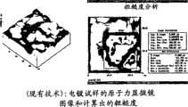
图11a和11b所示为使用离子辅助物理气相沉积方法和电镀方法制造出的涂层的原子力显微镜图像和粗糙度分析的对比图;Figures 11a and 11b show a comparison of AFM images and roughness analyzes of coatings fabricated using ion-assisted physical vapor deposition and electroplating;
图12为本发明中的导电涂层以及现有技术涂层的接触电阻的曲线图;Fig. 12 is the graph of the contact resistance of conductive coating among the present invention and prior art coating;
图13为通过比较本发明的不锈钢导电涂层、未涂覆的不锈钢基体和Poco石墨得到的电池电压对电流密度和接触电阻的极化曲线图;Fig. 13 is the polarization curve diagram of the battery voltage obtained by comparing the stainless steel conductive coating of the present invention, the uncoated stainless steel substrate and Poco graphite to the current density and the contact resistance;
图14为在80℃下的充气溶液中,循环电位在+0.4和+0.6V(vs.Ag/AgCl)之间的腐蚀电流曲线图;和Figure 14 is a graph of corrosion current at cyclic potentials between +0.4 and +0.6V (vs. Ag/AgCl) in an aerated solution at 80°C; and
图15为在80℃条件下工作的充气模拟燃料电池溶液中,在+0.6V(Ag/AgCl)外加电位下涂覆10纳米金的不锈钢试样的恒电位暂态曲线图。Fig. 15 is a constant potential transient curve of a stainless steel sample coated with 10nm gold at an applied potential of +0.6V (Ag/AgCl) in a gas-filled simulated fuel cell solution working at 80°C.
具体实施方式Detailed ways
以下对优选实施例的描述本质上仅仅是示例性的,而非是对本发明、及其应用或者使用的限定。The following description of the preferred embodiments is merely exemplary in nature and not limiting of the invention, its application or uses.
图1示出了具有被导电的流体分配部件8,此后称为双极板8,相互间隔开的一对膜电极组件(MEAs)4和6的由两个电池构成的双极燃料电池堆2。MEAs 4和6以及双极板8在不锈钢夹板或者端板10和12之间,以及端部接触部件14和16之间叠置在一起。端部接触部件14和16,以及双极板8的两个工作表面分别具有多条沟槽或者通道18、20、22和24,用以向MEAs 4和6分配燃料和氧化性气体(即H2和O2)。不导电的垫圈26、28、30和32在燃料电池堆的多个元件间提供密封和电绝缘。可透过气体的导电材料一般为压靠在MEAs 4和6的电极表面上的碳/石墨扩散纸34、36、38和40。端部接触部件14和16分别压靠在碳/石墨纸34和40上,而双极板8压靠在MEA 4的阳极表面上的碳/石墨纸36上,并且压靠在MEA 6的阴极表面上的碳/石墨纸38上。氧通过适当的供给管道42从贮罐46中被供应至燃料电池堆的阴极侧,而氢通过适当的供给管道44从贮罐48中被供应至燃料电池的阳极侧。另一种选择是,环境空气可以作为氧气源被供应至阴极侧,氢从甲醇或者汽油重整装置等中被供应至阳极。还提供用于MEAs 4和6的H2和O2侧的排气管道(未示出)。附加管道50、52和54用于向双极板8和端板14与16供应液体冷却剂。还设置从双极板8和端板14与16中排出冷却剂的适当的管道,但图中未示出。Figure 1 shows a bipolar
图2为可被用于根据本发明第一实施例的典型双极板56的分解视图。双极板56包括第一外部金属板58,第二外部金属板60,和处在第一金属板58和第二金属板60中间的内部金属垫板62。外部金属板58和60制造得尽可能薄,并且可以采用冲压、或者其他常规的金属板成型工艺成形。外部金属板58在其外侧具有第一工作表面59,所述第一工作表面面对着膜电极组件(未示出),并成形以提供流场57。流场57由在其间限定出多个沟槽66的多个凸台64所限定,所述沟槽构成了“流场”,燃料电池的反应气体(即H2或O2)从双极板的一侧68通过所述“流场”沿曲折的路径流向其另一侧。当燃料电池完全组装好后,凸台64压靠在多孔材料、碳/石墨纸36或38上,后者反过来压靠在MEAs 4和6上。为简便起见,图2只示出了两列凸台和沟槽。实际上,凸台和沟槽将覆盖在与碳/石墨纸36和38相接合的金属板58和60的整个外表面。反应气体从沿着燃料电池一侧68设置的总管72被供应至沟槽66,并通过紧邻燃料电池的相对侧70设置的另一总管74从沟槽66中排出。由图3可以更好地看出,板58的下侧包括在其间限定出多条通道78的脊76,在燃料电池工作过程中冷却剂经过所述通道78。如图3所示,冷却剂通道78位于每一个凸台64之下,而反应气体沟槽66位于每一个脊76之下。另一种选择是,板58可以是平的并且在单独的材料板上形成流场。Figure 2 is an exploded view of a typical
金属板60与板58相似。板60的内表面61如图2所示。在这点上,图中示出了在其间限定出多条通道82的多个脊80,冷却剂通过这些通道82从双极板一侧69流至另一侧71。与板58相类似并如图3最佳所示,板60的外侧具有工作表面63。形成板60以提供流场65。流场65由其上的限定出多个沟槽86的多个凸台84所限定,所述沟槽构成反应气体通过的流场。内部金属垫板62处在外板58和60中间,并且其中包括多个孔88,以允许冷却剂在板60上的沟槽82和板58上的通道78之间流动,由此打破层流边界层而产生湍流,增强与外板58和60的各自的内表面90和92间的热交换。由此,通道78和82在板58和60限定的内部空间形成冷却剂流场。
图4为图3的一部分的放大图,示出了位于第一板58上的脊76,以及位于通过粘结剂85粘结到垫板62上的第二板60上的脊80。4 is an enlarged view of a portion of FIG. 3
根据本发明,如图4最佳所示,双极板的工作表面59和63上覆盖有导电的、耐氧化的以及耐酸的涂层94,该涂层中含有从Ru、Rh、Pd、Ag、Ir、Pt和Os组成的组中选择的贵金属。优选涂层为金(Au)。涂层94的厚度小于80纳米,优选小于50纳米,更优选为10-20纳米。板58和60的内表面90和92也可以有选择地覆盖涂层94(未示出)。In accordance with the present invention, as best shown in FIG. 4, the working
本领域技术人员可以意识到的另一种选择是,仅仅涂覆凸台64、84,而不涂覆板58和60各自的沟槽66和86。由此,只涂覆彼此接触的邻近导电表面。Another option, which will be appreciated by those skilled in the art, is to coat only the
在第一实施例中,形成板58和60的金属基体含有腐蚀敏感的金属例如铝、钛或不锈钢。涂层94被直接涂覆在板58和60上。In a first embodiment, the metal matrix forming the
在第二实施例中,另一导电的流体分配部件100的横截面视图如图5所示。部件100由具有泡沫流场106的薄基板102构成。该双极板的特征在于优选由固体钛金属板制得的薄隔板102,泡沫材料106(大约二分之一至约3毫米厚)通过焊接或钎焊附接到其两侧上。板102形成了阻气层,而泡沫材料106形成了流体流场。如图可见,泡沫材料106具有相对的主表面110和111。泡沫材料106的一个主表面110面对金属板102,而另一个主表面111背对110。一般来说,主表面111面对MEA。如图5和图6所示,主表面111形成导电部件100的外表面。泡沫材料可以由金属泡沫材料或者碳基泡沫材料制成。可制成固体泡沫材料的金属包括铜、铝、镍、钛、银和不锈钢,并且金属优选为镍和不锈钢。多种泡沫金属可以从位于俄亥俄州辛辛那提的AstroMet获得。制造这些金属泡沫材料的方法在专利号为No.4,973,358的美国专利中有记载。碳基泡沫材料可以从Ultra Met获得。一方面,如图5所示,贵金属涂层94被施加到板102上。In a second embodiment, a cross-sectional view of another electrically conductive
第二实施例的另一方面,基体102的涂层94和泡沫材料106依赖它们各自的特性而改变。取决于结构的材料以及基体102和泡沫材料106的布置,当使用金属板时可能有必要涂覆基体102的所有表面。当使用金属泡沫材料时,可以选择涂覆泡沫材料106的所有内部和外部表面,也可以选择仅仅涂覆部分表面。应该理解,此处讨论的泡沫材料106为开放式泡沫材料。这表明,整个泡沫材料106中存在着连续流动路径或者通道,这是由相互间开放穿透泡沫材料106厚度的连续开口或者孔形成的。泡沫材料106的外表面109指前述主表面比如110和111,它们包括由表面孔形成的开口。泡沫材料的内表面通过如图5所示的内部开口或孔108形成。In another aspect of the second embodiment, the
在第二实施例方面,可能覆盖全部内部开口108,面对MEA和面对基体平面板102的泡沫材料106的所有外表面109。(图6a)如果使用化学性能不稳定的泡沫材料比如铝或镍,这将是所需的。板102的表面可有选择地进行涂覆。如果使用化学性能更加稳定的泡沫材料比如不锈钢,泡沫材料106的外表面和内表面可以不用涂层,这取决于电池环境。在这个例子中,泡沫材料内部也可以保持未涂覆,或者涂覆至给定的深度。优选地,涂层94被涂覆到泡沫材料106的需要将电子从一种介质传送到下一种介质的部分上,例如从泡沫材料表面111传送至MEA,或者从泡沫材料表面110传送至平面板102。可以看到,在该实施例中(图6b),涂层94被施加到导电部件100上,在导电部件100的结构中电子流入、流出。一旦电子流过部件100,即泡沫材料106结构,在泡沫材料106中不存在电阻,并且在电子离开泡沫材料到或在金属板102表面上遇到下一个电阻区。在该实施例中,涂层94被施加在泡沫材料106的主表面111上,深度小于80纳米,优选小于50纳米,并且最优选深度范围为10-20纳米。此外在该实施例中,还可以在泡沫材料106的面对金属平面板102的主表面110上涂覆涂层,深度为10-20纳米。In terms of the second embodiment, it is possible to cover all
在第三实施例中,如图7所示,导电涂层94可以沉积到另一个导电的流体分配部件112上,该导电的流体分配部件包含聚合材料113,所述聚合材料中含有具有提供穿过可使用的部件的传导路径的穿越平面取向的导电纤维填料114。聚合材料113优选为合适的热固性聚合物,并且更优选自包括硅氧烷、聚异丁烯、环氧、乙烯基酯和酚醛树脂组成的组。另一种选择是,聚合材料113优选为热塑性材料,并且更优选自包括聚丙烯、乙烯-四氟乙烯(ETFE)、尼龙和橡胶改性聚丙烯组成的组。虽然前述热固性和热塑性聚合物优选含有导电纤维填料,但是依据应用的特定设计说明,本领域技术人员易于认识到选择其他类似材料也是适合的。例如,可以使用其它导电聚合物,比如聚乙炔,而不需要导电纤维填料。In a third embodiment, as shown in FIG. 7, a
根据第三实施例(图7),导电纤维填料114包括具有纵横比(即长度和厚度的比例)大于约5∶1,并具有良好的导电性和导热性的纤维材料。在这点上,当前优选的导电纤维材料包括碳纤维(比如沥青基纤维,PAN基纤维或者其他),石墨纤维,涂覆金属的石墨纤维(比如涂覆金的纤维)和各种金属纤维包括不锈钢纤维。虽然纤维状的导电填料114一般具有大于5∶1的纵横比,导电纤维更优选具有大于10∶1的纵横比,最有选大于15∶1的纵横比。According to a third embodiment (FIG. 7), the conductive
除了聚合材料113和导电纤维填料114外,本发明的复合物还可以有选择地含有1%至10%体积百分比的非导电纤维材料,用于加强复合材料的机械性能。如当前优选的,非导电纤维填料可以选自玻璃纤维。相似地,复合材料可包括体积百分比高达10%的导电非纤维材料。如当前优选的,导电非纤维材料可以优选自包括碳黑、石墨粉末和金属基粉末组成的组。现有技术中的例子,比如参见美国专利US6,096,450,US 6,103,413和US 6,248,467。在该实施例中(图7),金属涂层改善了复合材料到燃料电池的下一邻接部件间的导电性。In addition to the
在第四实施例中,如图8a和8b所示,可以使用的导电的流体分配部件为聚合双极板116,其含有许多设置在聚合体部分中的导电纤维118,每根导电纤维118以穿越平面的构形从聚合体部分的第一表面120连续延伸至聚合体部分的第二表面122。In a fourth embodiment, shown in Figures 8a and 8b, the conductive fluid distribution member that can be used is a polymeric bipolar plate 116 containing a number of conductive fibers 118 disposed in a polymeric portion, each conductive fiber 118 The cross-plane formations extend continuously from the first surface 120 of the polymeric portion to the second surface 122 of the polymeric portion.
主体部分124由具有相对高的强度、适合的热性能和对于冷却流体和反应气体低的渗透性的聚合材料构成。优选地,主体部分124由坚韧的导热聚合物比如填充碳的环氧构成。但是,主体部分124也可以由具有所需性能的其他合适材料构成。比如主体部分124可以由硅氧烷、聚异丁烯、聚乙烯酯、聚酯、酚醛、聚丙烯、ETFE、尼龙或者聚丙烯改性橡胶构成。可以通过在聚合物中加入碳、石墨或者贵金属颗粒加强导热性能。The main body portion 124 is constructed of a polymeric material having relatively high strength, suitable thermal properties, and low permeability to cooling fluids and reactive gases. Preferably, body portion 124 is constructed of a tough thermally conductive polymer such as carbon-filled epoxy. However, body portion 124 may also be constructed of other suitable materials having desired properties. For example, the body portion 124 may be constructed of silicone, polyisobutylene, polyvinyl ester, polyester, phenolic, polypropylene, ETFE, nylon, or polypropylene-modified rubber. Thermal conductivity can be enhanced by adding carbon, graphite or noble metal particles to the polymer.
设置在双极板116的主体部分124内的管状部件126可操作地限定了使冷却流体通过隔板以调节其热能的穿过其中的第二流场。管状部件126适于使冷却流体通过管道以从燃料电池堆中排出(或增加)热能。将管状部件126流体连接到管道上的冷却剂集管应该具有电绝缘性以消除在纤维118和管状部件126之间的分路电流。A tubular member 126 disposed within the body portion 124 of the bipolar plate 116 operably defines a second flow field therethrough for passing a cooling fluid through the separators to condition its thermal energy. Tubular member 126 is adapted to pass cooling fluid through the conduits to remove (or add to) thermal energy from the fuel cell stack. The coolant header fluidly connecting the tubular member 126 to the pipes should be electrically insulated to eliminate shunt current between the fibers 118 and the tubular member 126 .
如当前优选的,管状部件126由填充碳的聚合物制造。但是,可以想到:管状部件126可以由任何种类具有热传导性并且对在燃料电池堆中使用的常用气体反应物质或者冷却剂具有耐蚀性的材料制成。其它一些适合的材料包括钛、碳或者不锈钢。As currently preferred, tubular member 126 is fabricated from a carbon-filled polymer. However, it is contemplated that tubular member 126 may be made of any type of material that is thermally conductive and resistant to common gaseous reactants or coolants used in fuel cell stacks. Some other suitable materials include titanium, carbon or stainless steel.
设置在隔板内的导电部件118一般为完全在平面中取向,并从隔板的上表面128连续延伸到隔板的下表面130以将隔板的体电阻率减至最小,如图8a所示。每个导电部件118为伸长的纤维(即纵横比为2000∶1或者更大)。从图8a可以看到,第一端部132暴露在上表面128处而第二端部134暴露在下表面130处。Conductive features 118 disposed within the separator are generally oriented entirely in-plane and extend continuously from the upper surface 128 of the separator to the lower surface 130 of the separator to minimize the bulk resistivity of the separator, as shown in FIG. 8a. Show. Each conductive member 118 is an elongated fiber (ie, has an aspect ratio of 2000:1 or greater). It can be seen from FIG. 8 a that the first end portion 132 is exposed at the upper surface 128 and the second end portion 134 is exposed at the lower surface 130 .
现在参见图8b,导电涂层94已沉积到聚合物双极板116上,以使导电部件118接触导电涂层94。导电部件118由碳基导电纤维如沥青基纤维,PAN基纤维或者其他材料制造。导电部件118还可以由其他适合导电纤维材料比如石墨纤维、涂覆金的石墨纤维、涂覆铂的石墨纤维、金纤维、铂纤维或者涂覆的不锈钢纤维制造。在图8a和8b中,所使用的导电部件118与导电涂层94相结合增强了相邻双极板间的导电性。Referring now to FIG. 8 b ,
明显的是,可以预期在任何组合的泡沫材料或者平板表面上施加导电涂层,并且还可以预期在整个厚度范围内涂覆任意所需厚度的泡沫材料。在复合材料或者纤维材料的情况下,金属涂层增强了或者至少促进了导电性同样也是明显的。Clearly, it is contemplated to apply the conductive coating to any combination of foam or slab surfaces, and it is also contemplated to apply any desired thickness of foam over a range of thicknesses. In the case of composite or fiber materials, it is likewise evident that the metallic coating enhances or at least facilitates the electrical conductivity.
现在参照图9描述将导电涂层94沉积到上述四个实施例中所述的双极板上的方法。为了将导电涂层94沉积到基体上,使用离子辅助-物理气相沉积(PVD)方法。Referring now to FIG. 9, a method of depositing a
从图9可以看出,可以使用离子辅助-PVD设备136。设备136包括沉积室138和两个用于沉积金属涂层的电子枪A和B。设备136还包括用于溅射清洗基体的低能离子枪,以及可以使该设备在超高真空下工作的涡轮泵。As can be seen from Figure 9, an ion assist-PVD device 136 may be used. Apparatus 136 includes a deposition chamber 138 and two electron guns A and B for depositing metal coatings. The device 136 also includes a low energy ion gun for sputter cleaning of substrates, and a turbo pump that allows the device to operate under ultra-high vacuum.
将由导电涂层94涂覆的基体放置在沉积室138内。一旦将基体放进室138中,压力降低至大约10-4Torr。在沉积室中的第一坩锅140保持着贵金属进行沉积。假如要沉积金属或者贵金属的组合,第二金属由第二坩锅142保持。比如,含有钛的坩锅140用来沉积第一层,而含有金的坩锅142用来在钛上沉积第二层,这样的情况没有超出本发明的范围。另一种有效的选择是同时沉积多种金属组合。A substrate coated with
离子枪被用于溅射清洗基体。当离子枪溅射清洗基体时,电子束被用于熔化和蒸发贵金属。贵金属由此以0.10纳米/s的速度沉积在基体上,厚度小于80纳米,该现象可通过厚度监控器观察到。An ion gun is used to sputter clean the substrate. While ion guns sputter clean substrates, electron beams are used to melt and evaporate precious metals. The noble metal is thus deposited on the substrate at a rate of 0.10 nm/s with a thickness of less than 80 nm, which can be observed with a thickness monitor.
离子辅助-物理气相沉积方法的独特的方面是可以基本同时进行对基体的溅射清洗和沉积导电涂层。通过同时溅射清洗和涂覆基体,导电涂层94沉积在基体上的厚度可以非常小,小于80纳米,优选小于50纳米,最有选10-20纳米。当导电涂层94的厚度为10-20纳米时,导电涂层担载量优选为0.02-0.04mg/cm2。A unique aspect of the ion-assisted-physical vapor deposition method is that sputter cleaning of the substrate and deposition of the conductive coating can be performed substantially simultaneously. By simultaneously sputter cleaning and coating the substrate, the
本发明的方法对顺序清洗和沉积方法进行了改进。当所使用的基体为金属基体比如钛或者不锈钢时,在开始清洗和将金属物理气相沉积到基体上之间会形成氧化物膜。通过同时清洗基体和沉积贵金属,氧化层被完全和连续去除,由此防止或者至少显著减少了表面氧化物或者其他污垢的形成。由于去除氧化物层所需的离子能量低,因此可以实现同时清洗基体和沉积贵金属。由于离子能量低,轰击离子流一般小于由电子枪A和B发射出的沉积原子流。这是由于被除去的氧化物轻于沉积在基体上作为导电涂层94的金属。同样的,低能离子枪除去的仅仅是氧化层而非导电涂层94。结果是沉积在基体上的导电涂层94具有优良的粘附性能。此外,有可能涂覆非常薄的膜层,厚度在10-20纳米范围内,由此获得好的表面覆盖度,相对均匀的覆盖,以及良好的附着性能。由此,使用离子辅助PVD沉积方法可使贵金属非常光滑地、均匀地以及薄地沉积在基体上。The method of the present invention improves upon sequential cleaning and deposition methods. When the substrate used is a metal substrate such as titanium or stainless steel, an oxide film will form between the start of the cleaning and the physical vapor deposition of the metal onto the substrate. By simultaneously cleaning the substrate and depositing the noble metal, the oxide layer is completely and continuously removed, thereby preventing or at least significantly reducing the formation of surface oxides or other fouling. Due to the low ion energy required to remove the oxide layer, it is possible to simultaneously clean the substrate and deposit the noble metal. Due to the low energy of the ions, the bombardment ion flux is generally smaller than the deposition atom flux emitted by electron guns A and B. This is due to the oxide being removed being lighter than the metal deposited as
应该理解,本发明的重要特征是在基本上干净的表面上沉积金属涂层。在优选方面,离子枪对基体表面的清洗刚好在金属沉积开始之前进行。由此,清洗和金属沉积同时进行完成沉积处理。It should be understood that an important feature of the present invention is the deposition of a metal coating on a substantially clean surface. In a preferred aspect, cleaning of the substrate surface by the ion gun occurs just before metal deposition begins. Thus, cleaning and metal deposition are carried out simultaneously to complete the deposition process.
如上所述,通过在干净的表面上沉积金属涂层,涂层的附着性显著提高,由此抵抗从基体上脱层。比如,当涂层在0.5M H2SO4溶液中受到10mA/cm2-50mA/cm2范围内的循环外加阴极电流的作用时,有氢气(H2)产生,导致现有技术涂层从基体上脱层和剥落。但是,当使用本发明的离子辅助-物理气相沉积方法沉积涂层时,涂层在基体的清洁表面上的优良附着力可以抵抗由在阴极电流作用下释放的氢气(H2)导致的基体脱层。As mentioned above, by depositing a metallic coating on a clean surface, the adhesion of the coating is significantly improved, thereby resisting delamination from the substrate. For example, when the coating is subjected to a cyclic external cathodic current in the range of 10mA/cm2 -50mA/cm2 in 0.5M H2 SO4 solution, hydrogen (H2 ) is generated, causing the prior art coating to dissipate from the substrate Delamination and peeling. However, when the coating is deposited using the ion-assisted-physical vapor deposition method of the present invention, the excellent adhesion of the coating on the clean surface of the substrate can resist the detachment of the substrate caused by hydrogen gas (H2 ) released under the action of cathodic current. layer.
还应该理解,离子辅助-PVD方法是对现有的沉积方法比如金的溅射的改进。这是由于溅射中对等离子体的控制是不规则的,因为不能调整入射到基体上的离子的方向、能量和流量。相反,由于在离子辅助-PVD方法中使用的离子束能量低并较好地进行准直,仅具有很小的发散角,因此离子辅助-PVD方法可以独立控制沉积参数。It should also be understood that the ion-assisted-PVD method is an improvement over existing deposition methods such as sputtering of gold. This is due to the irregular control of the plasma in sputtering because the direction, energy, and flux of ions incident on the substrate cannot be adjusted. In contrast, the ion-assisted-PVD method can independently control the deposition parameters because the ion beam used in the ion-assisted-PVD method has low energy and is well collimated and has only a small divergence angle.
现在详细描述本发明的优选实施例的实施细节。在该优选实施例中,选择金作为贵金属,以使用离子辅助-PVD方法将其沉积在316L不锈钢基体上。Implementation details of the preferred embodiment of the present invention will now be described in detail. In this preferred embodiment, gold was chosen as the noble metal to be deposited on a 316L stainless steel substrate using an ion-assisted-PVD method.
在第一系列试验中,在超高真空条件下使用电子束蒸发法将金沉积到不锈钢基体上。不锈钢基体在超声波浴中首先用丙酮然后用甲醇分别清洗15分钟。发现金涂层的附着力十分差。In the first series of experiments, gold was deposited onto a stainless steel substrate using electron beam evaporation under ultra-high vacuum conditions. The stainless steel substrate was cleaned first with acetone and then with methanol for 15 minutes in an ultrasonic bath. The adhesion of the gold coating was found to be very poor.
在第二系列试验中,在沉积金之前,不锈钢基体先被喷砂,之后用丙酮、甲醛超声波浴进行清洗。附着性能提高了,但是涂层放入腐蚀测试溶液后失效。In the second series of experiments, stainless steel substrates were grit-blasted and then cleaned with an acetone-formaldehyde ultrasonic bath prior to gold deposition. Adhesion improved, but the coating failed when placed in the corrosion test solution.
在第三系列试验中,不锈钢基体在被放入丙酮、然后是甲醛超声波浴中进行清洗前先进行电化学清洗。再一次,金的附着性能提高了,但是涂层放入腐蚀测试溶液后失效。In the third series of experiments, stainless steel substrates were electrochemically cleaned before being placed in an ultrasonic bath of acetone followed by formaldehyde. Again, gold adhesion improved, but the coating failed when placed in the corrosion test solution.
在第四系列试验中,使用本发明的离子辅助-PVD方法。所用离子枪为2-10分钟具有电流密度为1-20mA/cm2的100-500eVAr+束。蒸发源材料为从Johnson-Matthey得到的99.99%的纯金。所用316L不锈钢基体为2.54cm×2.54cm样片,先在丙酮超声波浴中,然后在甲醇超声波浴中分别清洗15分钟。然后将不锈钢基体装入离子辅助-PVD设备的沉积室中并保持在其中直至压力小于2×10-7Torr。沉积室的基准压力一般在10-9Torr中间的范围内,并始终低于1×10-8Torr。随着离子枪清洗不锈钢基体,金涂层通过单一电子束蒸发源在35℃至40℃条件下以0.10纳米/s的速度进行沉积。即使放入腐蚀测试溶液中近100小时后,金涂层也显示出优良的附着性能。In a fourth series of experiments, the ion-assisted-PVD method of the present invention was used. The ion gun used was a 100-500 eVAr+ beam with a current density of 1-20 mA/cm2 for 2-10 min. The evaporation source material was 99.99% pure gold obtained from Johnson-Matthey. The 316L stainless steel substrate used was a 2.54cm×2.54cm sample, which was first cleaned in an acetone ultrasonic bath and then in a methanol ultrasonic bath for 15 minutes. The stainless steel substrate was then loaded into the deposition chamber of the ion-assisted-PVD apparatus and kept there until the pressure was less than 2×10⁻⁷ Torr. The base pressure of the deposition chamber is generally in the range of 10-9 Torr and always below 1 x 10⁻⁸ Torr. With the ion gun cleaning the stainless steel substrate, the gold coating was deposited by a single electron beam evaporation source at a rate of 0.10 nm/s at 35°C to 40°C. Even after being placed in the corrosion test solution for nearly 100 hours, the gold coating showed excellent adhesion properties.
与已有的沉积技术比如电镀相比,本发明具有显著的优点。例如,在基体上电镀沉积贵金属是非常昂贵的。这是由于当基体为不锈钢、铝或钛时,为了防止基体发生腐蚀需要具有大约100纳米或者更大厚度的涂层。此外,当使用电镀时,贵金属对基体的附着力差。由此,为了提高附着力,需要使用另一种金属比如镍的中间层。除了在燃料电池环境中不稳定外,这还进一步增加了制造成本。本发明的离子辅助方法不需要中间层,并且厚度可以仅为10-20纳米,由此减少了生产成本。The present invention has significant advantages over existing deposition techniques such as electroplating. For example, galvanic deposition of noble metals on substrates is very expensive. This is because when the substrate is stainless steel, aluminum or titanium, it is necessary to have a coating having a thickness of about 100 nm or more in order to prevent corrosion of the substrate. In addition, precious metals have poor adhesion to the substrate when electroplating is used. Thus, in order to improve the adhesion, it is necessary to use an interlayer of another metal such as nickel. In addition to being unstable in a fuel cell environment, this further increases manufacturing costs. The ion-assisted method of the present invention does not require an intermediate layer, and the thickness can be only 10-20 nanometers, thereby reducing production costs.
另外,参见图10a和10b,当使用离子辅助-PVD方法时,可在基体上沉积出光滑和均匀的金属涂层(图10a)。在基体上沉积光滑和均匀的涂层可以防止腐蚀。相反,电镀涂层粗糙并多孔(图10b)。电镀涂层具有许多尖峰和凹谷,不能保证基体被全部涂覆而导致基体发生腐蚀。这些尖峰和凹谷也不能保证在凹谷处的电连接。此外,在凹谷中依然可能存在氧化物,可能污染燃料电池。这在图11a和图11b中更清楚地示出。In addition, referring to Figures 10a and 10b, when using the ion-assisted-PVD method, a smooth and uniform metal coating can be deposited on the substrate (Figure 10a). Depositing a smooth and uniform coating on the substrate prevents corrosion. In contrast, the electroplated coating was rough and porous (Fig. 10b). Electroplated coatings have many peaks and valleys, which cannot guarantee that the substrate is completely coated and cause corrosion of the substrate. These peaks and valleys also do not guarantee electrical connection at the valleys. In addition, oxides may still be present in the valleys, possibly contaminating the fuel cell. This is shown more clearly in Figures 11a and 11b.
图11a示出了用本发明离子辅助-PVD方法制造的金涂层的原子力显微图像。如图11a所示,涂层光滑均匀。同时进行了粗糙度分析和峰-谷范围分析。离子辅助-PVD涂层的平均粗糙度(Ra)仅为184.78纳米,峰-谷范围(Z)仅为1.119微米。峰-谷范围应该小于3.000微米,理想的小于2.800微米,更理想的小于2.500微米,优选小于2.000微米,最优选小于1.500微米。本发明的涂层具有这样平滑和均匀的表面,可以确保维持双极板之间的电接触。同时,光滑和均匀的表面还确保未被离子辅助-PVD方法除去的氧化物被完全覆盖,防止其污染燃料电池。Figure 11a shows an atomic force microscopy image of a gold coating fabricated using the ion-assisted-PVD method of the present invention. As shown in Figure 11a, the coating is smooth and uniform. Simultaneous roughness analysis and peak-to-valley range analysis were performed. The average roughness (Ra ) of the ion-assisted-PVD coating is only 184.78 nm, and the peak-to-valley range (Z) is only 1.119 microns. The peak-to-valley range should be less than 3.000 microns, ideally less than 2.800 microns, more desirably less than 2.500 microns, preferably less than 2.000 microns, most preferably less than 1.500 microns. The coating of the present invention has such a smooth and uniform surface that it is ensured that electrical contact between the bipolar plates is maintained. At the same time, the smooth and uniform surface also ensures that oxides not removed by the ion-assisted-PVD method are completely covered, preventing them from contaminating the fuel cell.
相反,如图11b所示,电镀涂层的原子力显微图像显示该涂层粗糙并多孔。存在许多突出的结。电镀涂层的粗粗度分析以及峰-谷范围分析显示平均粗糙度(Ra)为415.88纳米,峰-谷范围(Z)为2.860微米。因此,电镀涂层上的峰和谷不能确保双极板间的电接触。电镀涂层也不能确保所有的会污染燃料电池的氧化物被除去或者被覆盖。In contrast, as shown in Figure 11b, the AFM image of the electroplated coating revealed that the coating was rough and porous. There are many prominent knots. Roughness analysis and peak-to-valley range analysis of the electroplated coating showed an average roughness (Ra ) of 415.88 nm and a peak-to-valley range (Z) of 2.860 microns. Therefore, the peaks and valleys on the electroplated coating do not ensure electrical contact between the bipolar plates. Electroplated coatings also do not ensure that all oxides that can contaminate the fuel cell are removed or covered.
本发明的另一个优点是,如上所述以及在第一实施例中所述,在板58和60(图2)的内表面90和92上的可选涂层确保了保持板58和60之间的电接触。一般来说,板58和60由粘结剂(未示出)粘合在一起。但是当使用粘结剂时,在板58和60之间可使用的冷却剂会破坏粘结剂的完整性,由此导致板58和60之间的电阻显著增加。通过使用本发明的导电涂层94涂覆板58和60的内表面90和92,可以使板58和60之间的电阻在更长的持续时间内保持最低。Another advantage of the present invention is that, as described above and in the first embodiment, the optional coating on the
本发明的这一优点可通过将用粘结剂粘合的双极板放入80℃去离子水浴中进行检测。即使在5000小时后,双极板的板58和60之间的电阻仍然很小。这是由于涂层94与粘结剂具有良好的粘结性能,并改善了板58和60之间的电导。This advantage of the present invention was tested by placing the adhesive-bonded bipolar plates in a 80°C deionized water bath. Even after 5000 hours, the resistance between the
使用离子辅助-PVD方法沉积贵金属涂层的另一个优点是与商业上已公知的涂层比如Acheson相比,接触电阻受压力变化的影响很小。如图12所示。测试的试样为不锈钢基体上的20纳米Au,15纳米Au和10纳米金涂层。将Acheson(Acheson公司的导电碳基涂层)涂覆在钛基体上。接触电阻通过在来自Toray的两种扩散性能的纸之间压缩试样来测量。压力在50-200psi范围内变化,而外加电流密度为1A/cm2。通过测量扩散纸与金属试样之间通过涂层的电压降来测量接触电阻。如图12所示,10纳米,15纳米和20纳米金涂层在很宽的压力范围50-200psi内的接触电阻非常低。具体而言,接触电阻一般为1.5-6.5毫欧姆/cm2,在压力范围50-200psi内有很小百分比的损失。另一方面,Acheson涂层的接触电阻为12-31毫欧姆/cm2,在压力范围50-200psi内有相当大百分比的损失。本发明的低接触电阻使燃料电池堆中可使用低堆叠压力,从而延长电池堆的寿命并防止MEA中纤维发生碰撞。Another advantage of depositing noble metal coatings using the ion-assisted-PVD method is that the contact resistance is less affected by pressure changes compared to commercially known coatings such as Acheson. As shown in Figure 12. The samples tested were 20nm Au, 15nm Au and 10nm gold coatings on stainless steel substrates. Acheson (Acheson's conductive carbon-based coating) was coated on the titanium substrate. Contact resistance was measured by compressing the specimen between two diffusion properties papers from Toray. The pressure was varied in the range of 50-200 psi and the applied current density was 1 A/cm2 . Contact resistance is measured by measuring the voltage drop across the coating between the diffusion paper and the metal coupon. As shown in Figure 12, the 10nm, 15nm and 20nm gold coatings exhibit very low contact resistance over a wide pressure range of 50-200psi. Specifically, contact resistance is typically 1.5-6.5 milliohms/cm2 with a small percentage loss in the pressure range 50-200 psi. On the other hand, the Acheson coating has a contact resistance of 12-31 milliohms/cm2 with a significant percentage loss in the pressure range of 50-200 psi. The low contact resistance of the present invention allows the use of low stacking pressures in fuel cell stacks, thereby extending stack life and preventing fiber collisions in the MEA.
本发明关于接触电阻以及电池电压的效果可以从图13看出。图13为使用本发明方法涂覆10纳米Au的317L不锈钢基体,未经涂覆的317L不锈钢基体,以及Poco石墨基体的比较图。从图13可以看出,本发明的导电涂层与未经涂覆的不锈钢基体相比在电池电压、接触电阻上具有显著的优点。与Poco石墨基体相对比,本发明的导电涂层提供基本相同的电池电压,而提供较小的接触电阻。同时本发明的导电涂层整体上优于Poco石墨,其原因在于在不锈钢基体上制造本发明的导电涂层的成本更低。The effect of the present invention on contact resistance and battery voltage can be seen from FIG. 13 . FIG. 13 is a comparison diagram of a 317L stainless steel substrate coated with 10 nm Au, an uncoated 317L stainless steel substrate, and a Poco graphite substrate using the method of the present invention. It can be seen from FIG. 13 that the conductive coating of the present invention has significant advantages in battery voltage and contact resistance compared with the uncoated stainless steel substrate. Compared with the Poco graphite matrix, the conductive coating of the present invention provides substantially the same cell voltage, while providing a lower contact resistance. At the same time, the conductive coating of the present invention is better than Poco graphite as a whole, because the cost of manufacturing the conductive coating of the present invention on the stainless steel substrate is lower.
本发明的另一个优点在于导电涂层防止了双极板钝化。从图14可以看出,涂覆10纳米Au的不锈钢基体在80℃的充气溶液中在+0.4V-+0.6V(vs.Ag/AgCl)循环电位下,由此模拟双极板在燃料电池中的环境(pH=3.0,10ppm HF,以及0.5M Na2SO4作为辅助电解质)时,具有低的腐蚀电流。Another advantage of the present invention is that the conductive coating prevents passivation of the bipolar plate. It can be seen from Figure 14 that the stainless steel substrate coated with 10nm Au is under the cycle potential of +0.4V-+0.6V (vs. It has a low corrosion current in a medium environment (pH=3.0, 10ppm HF, and 0.5M Na2 SO4 as auxiliary electrolyte).
在空气中在+0.6V(vs.Ag/AgCl)下以及在氢气中在-0.4V(vs.Ag/AgCl)下,对涂覆在不锈钢基体上的10纳米Au进行超过100小时的恒电位腐蚀试验。如图15所示,在这些条件下测得的腐蚀电流非常低(低于1微安/cm2),显示涂层具有优良的稳定性。10 nm Au coated on stainless steel substrates were potentiostatically performed over 100 hours at +0.6 V (vs. Ag/AgCl) in air and -0.4 V (vs. Ag/AgCl) in hydrogen Corrosion test. As shown in Figure 15, the corrosion current measured under these conditions was very low (below 1 microampere/cm2 ), showing excellent stability of the coating.
从上面详细的描述可以看出,本发明在导电的流体分配部件上得到了超薄贵金属导电涂层,充分覆盖基体表面防止了腐蚀并降低了接触电阻,由此改进了燃料电池的整体性能。此外,由于在涂层上涂覆超低担载量的贵金属,导电的流体分配部件的生产成本可以保持最低。As can be seen from the above detailed description, the present invention obtains an ultra-thin conductive coating of noble metal on the conductive fluid distribution component, which fully covers the surface of the substrate to prevent corrosion and reduce contact resistance, thereby improving the overall performance of the fuel cell. In addition, the production cost of electrically conductive fluid distribution components can be kept to a minimum due to the ultra-low loading of precious metals applied to the coating.
上述实例和方法的描述本质上仅仅是示例性的,不偏离本发明要点的各种变化将在本发明的范围内。这样的变化不被视为偏离了本发明的精神和范围。The foregoing examples and description of methods are merely exemplary in nature and variations that do not depart from the gist of the invention are intended to be within the scope of the invention. Such variations are not to be regarded as a departure from the spirit and scope of the invention.
Claims (9)
Translated fromChineseApplications Claiming Priority (3)
| Application Number | Priority Date | Filing Date | Title |
|---|---|---|---|
| US10/163,393 | 2002-06-05 | ||
| US10/163,393US6866958B2 (en) | 2002-06-05 | 2002-06-05 | Ultra-low loadings of Au for stainless steel bipolar plates |
| PCT/US2003/017039WO2003105254A1 (en) | 2002-06-05 | 2003-05-30 | ULTRA-LOW LOADINGS OF Au FOR STAINLESS STEEL BIPOLAR PLATES |
Publications (2)
| Publication Number | Publication Date |
|---|---|
| CN1672274A CN1672274A (en) | 2005-09-21 |
| CN1672274Btrue CN1672274B (en) | 2012-05-02 |
Family
ID=29709962
Family Applications (1)
| Application Number | Title | Priority Date | Filing Date |
|---|---|---|---|
| CN038179792AExpired - LifetimeCN1672274B (en) | 2002-06-05 | 2003-05-30 | An electrically conductive fluid distribution component |
Country Status (6)
| Country | Link |
|---|---|
| US (2) | US6866958B2 (en) |
| JP (1) | JP4638731B2 (en) |
| CN (1) | CN1672274B (en) |
| AU (1) | AU2003274331A1 (en) |
| DE (1) | DE10392702B4 (en) |
| WO (1) | WO2003105254A1 (en) |
Cited By (1)
| Publication number | Priority date | Publication date | Assignee | Title |
|---|---|---|---|---|
| CN106876742A (en)* | 2017-04-19 | 2017-06-20 | 大连交通大学 | Diamond-like modified polymer electrolyte membrane fuel cell metal bipolar plate and preparation method thereof |
Families Citing this family (95)
| Publication number | Priority date | Publication date | Assignee | Title |
|---|---|---|---|---|
| US7592089B2 (en)* | 2000-08-31 | 2009-09-22 | Gm Global Technology Operations, Inc. | Fuel cell with variable porosity gas distribution layers |
| US6866958B2 (en)* | 2002-06-05 | 2005-03-15 | General Motors Corporation | Ultra-low loadings of Au for stainless steel bipolar plates |
| CA2435988A1 (en)* | 2002-07-25 | 2004-01-25 | Global Thermoelectric Inc. | Metal foam interconnect |
| JP4003942B2 (en)* | 2002-08-06 | 2007-11-07 | 本田技研工業株式会社 | Fuel cell separator and fuel cell |
| KR20040016378A (en)* | 2002-08-16 | 2004-02-21 | 대주전자재료 주식회사 | Separator for a fuel cell employing a solid polymer electrolytic membrane |
| US6838202B2 (en)* | 2002-08-19 | 2005-01-04 | General Motors Corporation | Fuel cell bipolar plate having a conductive foam as a coolant layer |
| US7009136B2 (en)* | 2002-10-09 | 2006-03-07 | General Motors Corporation | Method of fabricating a bipolar plate assembly |
| SE0302903L (en)* | 2003-11-04 | 2005-05-05 | Dieter Neidhardt | Device for enlarging an image on a monitor of an apparatus |
| US7344798B2 (en)* | 2003-11-07 | 2008-03-18 | General Motors Corporation | Low contact resistance bonding method for bipolar plates in a pem fuel cell |
| JP5403642B2 (en)* | 2003-11-07 | 2014-01-29 | 大同特殊鋼株式会社 | Corrosion resistant conductive material |
| US20050100774A1 (en)* | 2003-11-07 | 2005-05-12 | Abd Elhamid Mahmoud H. | Novel electrical contact element for a fuel cell |
| US8101319B2 (en) | 2004-05-20 | 2012-01-24 | GM Global Technology Operations LLC | Approach to make a high performance membrane electrode assembly (MEA) for a PEM fuel cell |
| US7419546B2 (en) | 2004-06-18 | 2008-09-02 | Basf Fuel Cell Gmbh | Gas diffusion electrodes, membrane-electrode assemblies and method for the production thereof |
| US7955754B2 (en)* | 2004-07-20 | 2011-06-07 | GM Global Technology Operations LLC | Enhanced stability bipolar plate |
| KR100637490B1 (en)* | 2004-09-17 | 2006-10-20 | 삼성에스디아이 주식회사 | Stack for Fuel Cell and Fuel Cell System with the Same |
| US7700212B2 (en)* | 2004-10-07 | 2010-04-20 | Gm Global Technology Operations, Inc. | Bipolar plate with enhanced stability |
| US7632592B2 (en) | 2004-11-01 | 2009-12-15 | Gm Global Technology Operations, Inc. | Method of fabricating corrosion-resistant bipolar plate |
| US7709145B2 (en)* | 2004-11-12 | 2010-05-04 | Gm Global Technology Operations, Inc. | Hydrophilic surface modification of bipolar plate |
| US20060216571A1 (en)* | 2005-03-24 | 2006-09-28 | Gayatri Vyas | Metal oxide based hydrophilic coatings for PEM fuel cell bipolar plates |
| US8182884B2 (en)* | 2005-02-28 | 2012-05-22 | GM Global Technology Operations LLC | Process for application of a hydrophilic coating to fuel cell bipolar plates |
| US8029943B2 (en)* | 2005-02-28 | 2011-10-04 | GM Global Technology Operations LLC | Method to make conductive hydrophilic fuel cell elements |
| US20060216570A1 (en)* | 2005-03-24 | 2006-09-28 | Gayatri Vyas | Durable hydrophilic coatings for fuel cell bipolar plates |
| US20060257711A1 (en)* | 2005-05-12 | 2006-11-16 | Elhamid Mahmoud H A | Electrically conductive fluid distribution plate for fuel cells |
| US8735016B2 (en) | 2005-05-12 | 2014-05-27 | GM Global Technology Operations LLC | Hydrophilic, electrically conductive fluid distribution plate for fuel cell |
| US8623573B2 (en)* | 2005-05-12 | 2014-01-07 | GM Global Technology Operations LLC | Porous, electrically conductive fluid distribution plate for fuel cells |
| US7759017B2 (en) | 2005-05-18 | 2010-07-20 | Gm Global Technology Operations, Inc. | Membrane electrode assembly (MEA) architecture for improved durability for a PEM fuel cell |
| US20070003813A1 (en)* | 2005-06-30 | 2007-01-04 | General Motors Corporation | Stable conductive and hydrophilic fuel cell contact element |
| US8377607B2 (en)* | 2005-06-30 | 2013-02-19 | GM Global Technology Operations LLC | Fuel cell contact element including a TiO2 layer and a conductive layer |
| US8017280B2 (en)* | 2005-07-13 | 2011-09-13 | GM Global Technology Operations LLC | Metal fluid distribution plate with an adhesion promoting layer and polymeric layer |
| WO2007021676A2 (en)* | 2005-08-12 | 2007-02-22 | Gm Global Technology Operations, Inc. | Fuel cell component with coating including nanoparticles |
| DE112006002140B4 (en) | 2005-08-12 | 2022-07-14 | GM Global Technology Operations LLC (n. d. Ges. d. Staates Delaware) | Hydrophilic coating for fuel cell bipolar plate and method of making same |
| US20070036890A1 (en)* | 2005-08-12 | 2007-02-15 | Feng Zhong | Method of making a fuel cell component using a mask |
| US7883819B2 (en)* | 2005-08-30 | 2011-02-08 | Gm Global Technologies Operations, Inc. | Hybrid electrically conductive fluid distribution separator plate assembly for fuel cells |
| US8470488B2 (en)* | 2005-11-23 | 2013-06-25 | GM Global Technology Operations LLC | Metallic bipolar plates with high electrochemical stability and improved water management |
| CN100362684C (en)* | 2005-11-25 | 2008-01-16 | 大连交通大学 | Surface modification process of stainless steel used as bipolar plate of proton exchange membrane fuel cell |
| US7897295B2 (en)* | 2005-12-20 | 2011-03-01 | GM Global Technology Operations LLC | Surface engineering of bipolar plate materials for better water management |
| US8574716B2 (en)* | 2006-01-23 | 2013-11-05 | Hitachi Chemical Co., Ltd. | Ionic polymer devices and methods of fabricating the same |
| US7870745B2 (en)* | 2006-03-16 | 2011-01-18 | Bsst Llc | Thermoelectric device efficiency enhancement using dynamic feedback |
| JP5200334B2 (en)* | 2006-05-29 | 2013-06-05 | トヨタ自動車株式会社 | Metal member having noble metal plating and method for manufacturing the same |
| US20070287057A1 (en) | 2006-06-09 | 2007-12-13 | Elhamid Mahmoud H Abd | Method for making a hydrophilic corrosion resistant coating on low grade stainless steel/alloys for bipolar plates |
| JP5050434B2 (en)* | 2006-07-27 | 2012-10-17 | トヨタ自動車株式会社 | Fuel cell |
| JP5205814B2 (en)* | 2006-08-09 | 2013-06-05 | 大同特殊鋼株式会社 | Metal separator for fuel cell and fuel cell using the same |
| US7807316B2 (en)* | 2006-11-01 | 2010-10-05 | Gm Global Technology Operations, Inc. | Fuel cell stack compression retention system with external springs |
| US8455155B2 (en)* | 2006-11-22 | 2013-06-04 | GM Global Technology Operations LLC | Inexpensive approach for coating bipolar plates for PEM fuel cells |
| FR2911219B1 (en)* | 2007-01-09 | 2009-05-15 | Conception Dev Michelin S A | BIPOLAR PLATE FOR FUEL CELL WITH POLYMERIC MEMBRANE |
| US7862936B2 (en)* | 2007-01-12 | 2011-01-04 | Gm Global Technology Operations, Inc. | Water removal channel for PEM fuel cell stack headers |
| US20080248358A1 (en)* | 2007-01-23 | 2008-10-09 | Canon Kabushiki Kaisha | Polymer electrolyte fuel cell and production method thereof |
| EP1978582A1 (en)* | 2007-04-05 | 2008-10-08 | Atotech Deutschland Gmbh | Process for the preparation of electrodes for use in a fuel cell |
| US8277986B2 (en) | 2007-07-02 | 2012-10-02 | GM Global Technology Operations LLC | Bipolar plate with microgrooves for improved water transport |
| US9011667B2 (en)* | 2007-09-27 | 2015-04-21 | GM Global Technology Operations LLC | Nanotube assembly, bipolar plate and process of making the same |
| US7741243B2 (en)* | 2007-10-05 | 2010-06-22 | Canon Kabushiki Kaisha | Production method of catalyst layer |
| KR100839193B1 (en)* | 2008-01-21 | 2008-06-17 | 현대하이스코 주식회사 | Metallic separator for fuel cell having coating layer in which carbon particles are dispersed in binder resin, and method for manufacturing same |
| US7891788B2 (en) | 2008-03-03 | 2011-02-22 | Silverbrook Research Pty Ltd | Printhead de-priming system with float valve isolation of printhead from ink reservoir |
| JP5291368B2 (en)* | 2008-03-28 | 2013-09-18 | Jx日鉱日石金属株式会社 | Fuel cell separator material, fuel cell separator using the same, fuel cell stack, and method for producing fuel cell separator material |
| US8148035B2 (en)* | 2008-05-16 | 2012-04-03 | GM Global Technology Operations LLC | Bipolar plate coating architecture for fuel cells and methods of making and using the same |
| KR101782808B1 (en)* | 2008-06-23 | 2017-09-28 | 누베라 퓨엘 셀스, 엘엘씨 | Fuel cell with reduced mass transfer limitations |
| US8758957B2 (en)* | 2008-07-29 | 2014-06-24 | GM Global Technology Operations LLC | Graphene coated SS bipolar plates |
| US9123920B2 (en)* | 2008-11-28 | 2015-09-01 | Jx Nippon Mining & Metals Corporation | Fuel cell separator material, fuel cell separator using same, and fuel cell stack |
| JP5222250B2 (en)* | 2009-08-20 | 2013-06-26 | 住友ゴム工業株式会社 | Run flat tire |
| ITMI20091531A1 (en)* | 2009-09-03 | 2011-03-04 | Industrie De Nora Spa | CONTINUOUS ACTIVATION OF ELECTROCLAMED STRUCTURES WITH VACUUM DEPOSITION TECHNIQUES |
| US8820610B2 (en)* | 2009-10-14 | 2014-09-02 | National University Corporation Gunma University | Using friction stir processing to form foamed metal precursors |
| TWI375347B (en)* | 2009-11-20 | 2012-10-21 | Ind Tech Res Inst | Manufacture method of bi-polar plates of fuel cell and bi-polar plates thereof |
| US8542465B2 (en) | 2010-03-17 | 2013-09-24 | Western Digital Technologies, Inc. | Suspension assembly having a microactuator electrically connected to a gold coating on a stainless steel surface |
| US8885299B1 (en) | 2010-05-24 | 2014-11-11 | Hutchinson Technology Incorporated | Low resistance ground joints for dual stage actuation disk drive suspensions |
| WO2011150458A1 (en)* | 2010-06-01 | 2011-12-08 | The University Of Queensland | A fuel cell stack |
| JP5634604B2 (en)* | 2010-06-24 | 2014-12-03 | ヒュンダイ ハイスコ | Separator for fuel cell and method for producing the same |
| US8665567B2 (en) | 2010-06-30 | 2014-03-04 | Western Digital Technologies, Inc. | Suspension assembly having a microactuator grounded to a flexure |
| TWI512129B (en)* | 2010-08-06 | 2015-12-11 | Industrie De Nora Spa | Continuous activation of electrodic structures by means of vacuum deposition techniques |
| DE102011004235A1 (en)* | 2011-02-16 | 2012-08-16 | Deutsches Zentrum für Luft- und Raumfahrt e.V. | Method for manufacturing carrier substrate for electrochemical device, involves forming protective film and/or protective film forming layer for defining inner surface of carrier material to obtain internally coated carrier material |
| WO2013022761A1 (en)* | 2011-08-05 | 2013-02-14 | Enerfuel, Inc. | Bipolar plate assembly having a recess and an insert member for placement in the recess |
| CN103703597B (en) | 2011-08-09 | 2016-02-10 | Jx日矿日石金属株式会社 | Fuel cell spacer material, use its fuel cell spacer and the manufacture method of fuel cell pack and fuel cell spacer material |
| WO2013138619A1 (en) | 2012-03-16 | 2013-09-19 | Hutchinson Technology Incorporated | Mid-loadbeam dual stage actuated (dsa) disk drive head suspension |
| CN104205216A (en) | 2012-03-22 | 2014-12-10 | 哈特奇桑科技公司 | Grounding Features for Disk Drive Head Suspension Flexures |
| DE102012103383A1 (en)* | 2012-04-18 | 2013-10-24 | Deutsches Zentrum für Luft- und Raumfahrt e.V. | Method for producing a carrier substrate, carrier substrate and electrochemical device |
| JP6251745B2 (en) | 2012-09-14 | 2017-12-20 | ハッチンソン テクノロジー インコーポレイテッドHutchinson Technology Incorporated | Gimbal-type flexible member having two-stage starting structure and suspension |
| WO2014059128A2 (en) | 2012-10-10 | 2014-04-17 | Hutchinson Technology Incorporated | Co-located gimbal-based dual stage actuation disk drive suspensions with dampers |
| US8941951B2 (en) | 2012-11-28 | 2015-01-27 | Hutchinson Technology Incorporated | Head suspension flexure with integrated strain sensor and sputtered traces |
| US8891206B2 (en) | 2012-12-17 | 2014-11-18 | Hutchinson Technology Incorporated | Co-located gimbal-based dual stage actuation disk drive suspensions with motor stiffener |
| US8896969B1 (en) | 2013-05-23 | 2014-11-25 | Hutchinson Technology Incorporated | Two-motor co-located gimbal-based dual stage actuation disk drive suspensions with motor stiffeners |
| US8717712B1 (en) | 2013-07-15 | 2014-05-06 | Hutchinson Technology Incorporated | Disk drive suspension assembly having a partially flangeless load point dimple |
| US8896970B1 (en) | 2013-12-31 | 2014-11-25 | Hutchinson Technology Incorporated | Balanced co-located gimbal-based dual stage actuation disk drive suspensions |
| US8867173B1 (en) | 2014-01-03 | 2014-10-21 | Hutchinson Technology Incorporated | Balanced multi-trace transmission in a hard disk drive flexure |
| US9070392B1 (en) | 2014-12-16 | 2015-06-30 | Hutchinson Technology Incorporated | Piezoelectric disk drive suspension motors having plated stiffeners |
| US9318136B1 (en) | 2014-12-22 | 2016-04-19 | Hutchinson Technology Incorporated | Multilayer disk drive motors having out-of-plane bending |
| JP2018028110A (en)* | 2014-12-25 | 2018-02-22 | 日本軽金属株式会社 | Conductive member made of aluminum, and production method thereof |
| US9296188B1 (en) | 2015-02-17 | 2016-03-29 | Hutchinson Technology Incorporated | Partial curing of a microactuator mounting adhesive in a disk drive suspension |
| CN107735834B (en) | 2015-06-30 | 2019-11-19 | 哈钦森技术股份有限公司 | Disk drive head suspension structure with improved reliability |
| JP6624704B2 (en) | 2015-08-31 | 2019-12-25 | 日立化成株式会社 | Molecular methods for assessing urothelial disease |
| US9646638B1 (en) | 2016-05-12 | 2017-05-09 | Hutchinson Technology Incorporated | Co-located gimbal-based DSA disk drive suspension with traces routed around slider pad |
| CN108123142B (en) | 2016-11-28 | 2022-01-04 | 财团法人工业技术研究院 | Corrosion-resistant structure and fuel cell comprising same |
| JP6887100B2 (en)* | 2016-12-26 | 2021-06-16 | パナソニックIpマネジメント株式会社 | Membrane electrode assembly and electrochemical hydrogen pump |
| CN109746611B (en)* | 2019-01-30 | 2024-04-26 | 安特(苏州)精密机械有限公司 | Welding fixture for metal bipolar plate |
| DE102020206774A1 (en) | 2020-05-29 | 2021-12-02 | Sgl Carbon Se | Bipolar flat element |
| CN113584441B (en)* | 2021-08-02 | 2023-11-07 | 杭州兴态环保科技有限公司 | Metal bipolar plate coating and preparation method thereof |
| JP7596231B2 (en) | 2021-08-13 | 2024-12-09 | 信越ポリマー株式会社 | Separator and manufacturing method thereof |
Citations (1)
| Publication number | Priority date | Publication date | Assignee | Title |
|---|---|---|---|---|
| CN1196584A (en)* | 1997-01-22 | 1998-10-21 | 德·诺拉有限公司 | Method of forming metal, its oxide layers on ion-conductive polymer membranes |
Family Cites Families (30)
| Publication number | Priority date | Publication date | Assignee | Title |
|---|---|---|---|---|
| US4214969A (en)* | 1979-01-02 | 1980-07-29 | General Electric Company | Low cost bipolar current collector-separator for electrochemical cells |
| US4519065A (en)* | 1980-09-22 | 1985-05-21 | Minnesota Mining And Manufacturing Company | Metallized information carrying discs |
| US5036252A (en)* | 1988-04-26 | 1991-07-30 | Hauzer Holding Bv | Radio frequency ion beam source |
| US4973358A (en)* | 1989-09-06 | 1990-11-27 | Alcan International Limited | Method of producing lightweight foamed metal |
| US5086035A (en)* | 1990-02-06 | 1992-02-04 | Eastman Kodak Company | Electrically conductive article (i) |
| US5786068A (en)* | 1991-05-03 | 1998-07-28 | Advanced Refractory Technologies, Inc. | Electrically tunable coatings |
| US5174870A (en)* | 1991-08-09 | 1992-12-29 | Pct Technology, Inc. | Electrocleaning method |
| EP0612538A3 (en)* | 1993-02-22 | 1995-04-05 | Cardiac Pacemakers Inc | Metallized, implantable cardiac electrode. |
| US5888593A (en)* | 1994-03-03 | 1999-03-30 | Monsanto Company | Ion beam process for deposition of highly wear-resistant optical coatings |
| US5508368A (en)* | 1994-03-03 | 1996-04-16 | Diamonex, Incorporated | Ion beam process for deposition of highly abrasion-resistant coatings |
| US5624769A (en)* | 1995-12-22 | 1997-04-29 | General Motors Corporation | Corrosion resistant PEM fuel cell |
| US5726524A (en)* | 1996-05-31 | 1998-03-10 | Minnesota Mining And Manufacturing Company | Field emission device having nanostructured emitters |
| US6051117A (en)* | 1996-12-12 | 2000-04-18 | Eltech Systems, Corp. | Reticulated metal article combining small pores with large apertures |
| FR2773644B1 (en)* | 1998-01-15 | 2000-02-04 | Alsthom Cge Alcatel | NON-SINTERED NICKEL ELECTRODE USED IN PARTICULAR IN ELECTROCHEMICAL GENERATORS WITH ALKALINE ELECTROLYTE AND BINDER FOR ACTIVE MATERIAL |
| US6096450A (en)* | 1998-02-11 | 2000-08-01 | Plug Power Inc. | Fuel cell assembly fluid flow plate having conductive fibers and rigidizing material therein |
| US6103413A (en)* | 1998-05-21 | 2000-08-15 | The Dow Chemical Company | Bipolar plates for electrochemical cells |
| US6248467B1 (en)* | 1998-10-23 | 2001-06-19 | The Regents Of The University Of California | Composite bipolar plate for electrochemical cells |
| EP1181728B1 (en)* | 1999-03-29 | 2003-05-14 | Siemens Aktiengesellschaft | Component such as a cell frame and/or pole plate for a pem fuel cell, with reduced contact resistance and method for reducing the contact resistance thereof |
| JP2001093538A (en)* | 1999-09-27 | 2001-04-06 | Nisshin Steel Co Ltd | Stainless steel low temperature fuel cell separator |
| KR100417050B1 (en)* | 1999-10-21 | 2004-02-05 | 마쯔시다덴기산교 가부시키가이샤 | Polymer electrolyte fuel cell |
| US6350539B1 (en)* | 1999-10-25 | 2002-02-26 | General Motors Corporation | Composite gas distribution structure for fuel cell |
| US6426863B1 (en)* | 1999-11-25 | 2002-07-30 | Lithium Power Technologies, Inc. | Electrochemical capacitor |
| JP4366872B2 (en)* | 2000-03-13 | 2009-11-18 | トヨタ自動車株式会社 | FUEL CELL GAS SEPARATOR, METHOD FOR PRODUCING THE FUEL CELL SEPARATOR, AND FUEL CELL |
| JP2001297777A (en)* | 2000-04-13 | 2001-10-26 | Matsushita Electric Ind Co Ltd | Polymer electrolyte fuel cell |
| US6649030B1 (en)* | 2000-08-31 | 2003-11-18 | Endovascular Technologies, Inc. | Physical vapor deposition of radiopaque markings on a graft |
| US6531238B1 (en)* | 2000-09-26 | 2003-03-11 | Reliant Energy Power Systems, Inc. | Mass transport for ternary reaction optimization in a proton exchange membrane fuel cell assembly and stack assembly |
| DE10058337A1 (en)* | 2000-11-24 | 2002-05-29 | Gen Motors Corp | Sheet product used as a bipolar plate in a fuel cell or in an electrolyzer has a conductive corrosion resistant protective coating made from a metal oxide on one side. |
| DE10065009B4 (en)* | 2000-12-23 | 2004-09-16 | Robert Bosch Gmbh | fuel cell |
| US7326669B2 (en)* | 2001-09-20 | 2008-02-05 | Honda Motor Co., Ltd. | Substrate having catalyst compositions on surfaces of opposite sides |
| US6866958B2 (en)* | 2002-06-05 | 2005-03-15 | General Motors Corporation | Ultra-low loadings of Au for stainless steel bipolar plates |
- 2002
- 2002-06-05USUS10/163,393patent/US6866958B2/ennot_activeExpired - Lifetime
- 2003
- 2003-05-30AUAU2003274331Apatent/AU2003274331A1/ennot_activeAbandoned
- 2003-05-30CNCN038179792Apatent/CN1672274B/ennot_activeExpired - Lifetime
- 2003-05-30DEDE10392702Tpatent/DE10392702B4/ennot_activeExpired - Lifetime
- 2003-05-30WOPCT/US2003/017039patent/WO2003105254A1/enactiveApplication Filing
- 2003-05-30JPJP2004512220Apatent/JP4638731B2/ennot_activeExpired - Fee Related
- 2005
- 2005-01-31USUS11/047,508patent/US7625654B2/ennot_activeExpired - Lifetime
Patent Citations (1)
| Publication number | Priority date | Publication date | Assignee | Title |
|---|---|---|---|---|
| CN1196584A (en)* | 1997-01-22 | 1998-10-21 | 德·诺拉有限公司 | Method of forming metal, its oxide layers on ion-conductive polymer membranes |
Cited By (1)
| Publication number | Priority date | Publication date | Assignee | Title |
|---|---|---|---|---|
| CN106876742A (en)* | 2017-04-19 | 2017-06-20 | 大连交通大学 | Diamond-like modified polymer electrolyte membrane fuel cell metal bipolar plate and preparation method thereof |
Also Published As
| Publication number | Publication date |
|---|---|
| US7625654B2 (en) | 2009-12-01 |
| US20050158607A1 (en) | 2005-07-21 |
| US20030228512A1 (en) | 2003-12-11 |
| US6866958B2 (en) | 2005-03-15 |
| WO2003105254A1 (en) | 2003-12-18 |
| JP4638731B2 (en) | 2011-02-23 |
| DE10392702B4 (en) | 2009-05-07 |
| CN1672274A (en) | 2005-09-21 |
| AU2003274331A1 (en) | 2003-12-22 |
| DE10392702T5 (en) | 2005-06-02 |
| JP2005529466A (en) | 2005-09-29 |
Similar Documents
| Publication | Publication Date | Title |
|---|---|---|
| CN1672274B (en) | An electrically conductive fluid distribution component | |
| CN100530765C (en) | Low Contact Resistance Connection Method for Bipolar Plates in Proton Exchange Membrane Fuel Cells | |
| JP4534353B2 (en) | Solid polymer electrolyte fuel cell | |
| JP5003823B2 (en) | Seal structure and fuel cell having the seal structure | |
| JP5391855B2 (en) | Conductive member, method for producing the same, fuel cell separator using the same, and polymer electrolyte fuel cell | |
| JP4073828B2 (en) | Solid polymer fuel cell and fuel cell separator | |
| US9382620B2 (en) | Electrical contact element for a fuel cell having an ultra-thin conductive layer coating | |
| US8101319B2 (en) | Approach to make a high performance membrane electrode assembly (MEA) for a PEM fuel cell | |
| JP5353205B2 (en) | Conductive member, method for producing the same, fuel cell separator and polymer electrolyte fuel cell using the same | |
| JP2010272490A (en) | Surface treatment member for fuel cell components and manufacturing method thereof | |
| JP5439965B2 (en) | Conductive member, method for producing the same, fuel cell separator using the same, and polymer electrolyte fuel cell | |
| JP2005142163A (en) | Electrical contact elements for fuel cells | |
| US8247138B2 (en) | Metal fluid distribution plate with an adhesion promoting layer and polymeric layer | |
| JP5287180B2 (en) | Laminated structure, manufacturing method thereof, and fuel cell using the same | |
| JP2007242407A (en) | Solid polymer electrolyte membrane cell and its components |
Legal Events
| Date | Code | Title | Description |
|---|---|---|---|
| C06 | Publication | ||
| PB01 | Publication | ||
| C10 | Entry into substantive examination | ||
| SE01 | Entry into force of request for substantive examination | ||
| C14 | Grant of patent or utility model | ||
| GR01 | Patent grant | ||
| CX01 | Expiry of patent term | Granted publication date:20120502 | |
| CX01 | Expiry of patent term |