CN1665738B - elevator door device - Google Patents
elevator door deviceDownload PDFInfo
- Publication number
- CN1665738B CN1665738BCN038161923ACN03816192ACN1665738BCN 1665738 BCN1665738 BCN 1665738BCN 038161923 ACN038161923 ACN 038161923ACN 03816192 ACN03816192 ACN 03816192ACN 1665738 BCN1665738 BCN 1665738B
- Authority
- CN
- China
- Prior art keywords
- door
- mentioned
- parts
- smoke
- boarding
- Prior art date
- Legal status (The legal status is an assumption and is not a legal conclusion. Google has not performed a legal analysis and makes no representation as to the accuracy of the status listed.)
- Expired - Fee Related
Links
Images


Classifications
- B—PERFORMING OPERATIONS; TRANSPORTING
- B66—HOISTING; LIFTING; HAULING
- B66B—ELEVATORS; ESCALATORS OR MOVING WALKWAYS
- B66B13/00—Doors, gates, or other apparatus controlling access to, or exit from, cages or lift well landings
- B66B13/30—Constructional features of doors or gates
- B66B13/308—Details of seals and joints
- B—PERFORMING OPERATIONS; TRANSPORTING
- B66—HOISTING; LIFTING; HAULING
- B66B—ELEVATORS; ESCALATORS OR MOVING WALKWAYS
- B66B13/00—Doors, gates, or other apparatus controlling access to, or exit from, cages or lift well landings
- B66B13/30—Constructional features of doors or gates
- B—PERFORMING OPERATIONS; TRANSPORTING
- B66—HOISTING; LIFTING; HAULING
- B66B—ELEVATORS; ESCALATORS OR MOVING WALKWAYS
- B66B13/00—Doors, gates, or other apparatus controlling access to, or exit from, cages or lift well landings
- B66B13/24—Safety devices in passenger lifts, not otherwise provided for, for preventing trapping of passengers
Landscapes
- Elevator Door Apparatuses (AREA)
- Specific Sealing Or Ventilating Devices For Doors And Windows (AREA)
- Power-Operated Mechanisms For Wings (AREA)
Abstract
Translated fromChinese
Description
Translated fromChinese技术领域technical field
本发明涉及一种防止烟从电梯的乘降场出入口向升降通路内流入或者从升降通路内向乘降场一侧流出的门装置的改进。另外,在以下的说明中,在表现「烟的侵入」的情况下,意味着烟的流入和流出中的任一种或者两者。The present invention relates to an improvement of a door device which prevents smoke from entering and exiting an elevator passageway into a lift passage or flowing out from the lift passage to a side of the landing place. In addition, in the following description, when expressing "invasion of smoke", it means either one or both of inflow and outflow of smoke.
背景技术Background technique
作为现有的装置,提出了图3至图5中所示的装置。图3为现有的电梯用门装置的主视图,图4为图3的A-A线向视图,图5为图3的B-B线向视图。As existing devices, devices shown in FIGS. 3 to 5 are proposed. Fig. 3 is a front view of a conventional elevator door device, Fig. 4 is a view taken along the line A-A of Fig. 3 , and Fig. 5 is a view taken along the line B-B of Fig. 3 .
在这些图中,101为在电梯乘降场出入口向两侧打开的乘降门,102为出入口的纵框,103为出入口的上框,104为门栏,由纵框102、上框103、门栏104包围着乘降场出入口的开口部。105a为设置在门101的侧部上、堵塞和纵框102之间的间隙的隔烟材料,105b为堵塞门101和上框103之间的间隙的隔烟材料,105c为插入门栏104的槽104a中、堵塞间隙的隔烟材料。另外,106为安装各个隔烟材料105a、105b、105c的螺钉。In these figures, 101 is the landing door that opens to both sides at the entrance and exit of the elevator landing, 102 is the vertical frame of the entrance, 103 is the upper frame of the entrance, and 104 is the door rail. The
这样构成的门装置由设置在门101周围的隔烟材料105a、105b、105c在关门时堵塞出入口纵框102、出入口上框103、门栏104之间的间隙,从而即使发生火灾,也不使烟向升降通路内流入,并不使烟通过升降通路向其他楼层的楼道扩散(例如参照日本国公开实用新型公报昭50-79184号、日本国公开特性公报昭63-112389号)。The door device constructed in this way blocks the gap between the entrance
但是,在现有的装置中,由于隔烟材料105a、105b、105c始终与对向的部件相接触,所以因门的正常开闭而磨损,其结果将必须要适当维修。另外,顺畅地进行乘降门101的开闭非常困难,经常受到滑动音的困扰。However, in the existing device, since the
而且,最近的电梯中增加了不带机械室的电梯,即驱动马达或控制盘等成为火源的机器配置在升降通路内的电梯(所谓无机械室电梯),与火灾发生时建筑物中成为火源的情况相配合,必须要采取即使烟的侵入方向来自乘降场、升降通路的任一侧也能够适当地防止其侵入的对策。另外,在现有的装置中,如图6所示,特别是在乘降门101相互的上方和下方上相当于门的部分的间隙107或图18的箭头所示部位,三个以上的部件相对向,所以还缺少堵塞间隙,适当地防止烟的侵入的措施。Moreover, elevators without a machine room have been added to the recent elevators, that is, elevators in which devices such as drive motors and control panels that become fire sources are arranged in the elevator passage (so-called elevators without a machine room), which is the same as in a building when a fire occurs. In accordance with the situation of the fire source, it is necessary to take appropriate measures to prevent the intrusion of smoke even if the intrusion direction is from either side of the landing area or the elevator passage. In addition, in the existing device, as shown in FIG. 6, especially in the
本发明是鉴于上述问题而提出的,其目的在于提供一种隔烟性能优良的电梯的门装置,在通常的门开闭时尤其不会带来障碍。The present invention has been made in view of the above-mentioned problems, and an object of the present invention is to provide an elevator door device having excellent smoke-insulating performance, which does not cause trouble especially when the normal door is opened and closed.
发明内容Contents of the invention
本发明是在包括出入口框和乘降门,所述出入口框设置在从乘降场通到升降通路的出入口上,由上框和纵框构成,所述乘降门隔开间隔地配置在该出入口框上,由门栏引导,开闭出入口框的开口部的门装置的电梯中,在乘降门的上部和侧部和底部、或者与乘降门的上部和侧部和底部对向的对向部件中的至少一方上具备阻止烟的侵入的隔烟部件。The present invention comprises an entrance and exit frame and a landing door. The entrance and exit frame is arranged on the entrance and exit from the landing field to the lifting passage, and is composed of an upper frame and a vertical frame. The landing and landing doors are arranged at intervals. On the entrance and exit frame, guided by the door rail, in the elevator of the door device that opens and closes the opening of the entrance and exit frame, on the upper part, side part and bottom of the landing door, or facing the upper part, side part and bottom of the landing door At least one of the facing members is provided with a smoke blocking member that prevents intrusion of smoke.
另外,本发明是在包括出入口框和乘降门,所述出入口框设置在从乘降场通到升降通路的出入口上,由上框和纵框构成,所述乘降门由隔开间隔地配置在该出入口框上,由门栏引导,开闭出入口框的开口部的高速门和低速门构成的门装置的电梯中,在高速门以及低速门的上部和侧部和底部、或者与高速门以及低速门的上部和侧部和底部对向的对向部件的至少一方上具备阻止烟的侵入的隔烟部件。In addition, the present invention includes an entrance and exit frame and a landing door. The entrance and exit frame is arranged on the entrance and exit from the landing field to the lifting passage, and is composed of an upper frame and a vertical frame. In the elevator of the door device composed of high-speed doors and low-speed doors that are arranged on the entrance and exit frame and guided by the door rail to open and close the opening of the entrance and exit frame, the upper, side and bottom of the high-speed door and the low-speed door, or the high-speed At least one of the facing members facing the top, side, and bottom of the door and the low-speed door is equipped with a smoke insulating member that prevents the intrusion of smoke.
附图说明Description of drawings
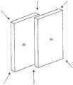
图1为表示电梯的门装置整体结构的立体图。Fig. 1 is a perspective view showing the overall structure of a door device for an elevator.
图2为表示本发明的门装置第1实施例的俯视图。Fig. 2 is a plan view showing a first embodiment of the door apparatus of the present invention.
图3为现有的电梯用乘降场隔烟门装置的主视图。Fig. 3 is a front view of a conventional elevator landing smoke door device.
图4为图3的A-A线向视图。Fig. 4 is a view along line A-A of Fig. 3 .
图5为图3的B-B线向视图。Fig. 5 is a view along the line B-B of Fig. 3 .
图6为说明现有技术的问题点的附图。FIG. 6 is a diagram illustrating problems of the prior art.
图7为图2中门装置下部的局部主视图。Fig. 7 is a partial front view of the lower part of the door device in Fig. 2 .
图8为图7中门装置上部的局部主视图。Fig. 8 is a partial front view of the upper part of the door device in Fig. 7 .
图9为图2的P部放大图。FIG. 9 is an enlarged view of part P in FIG. 2 .
图10为图7的Q部放大图。FIG. 10 is an enlarged view of part Q in FIG. 7 .
图11为图7的A-A线向视图。Fig. 11 is a view along the line A-A of Fig. 7 .
图12为图7的B-B线向视图。Fig. 12 is a view along the line B-B in Fig. 7 .
图13为图7的C-C线向视图。FIG. 13 is a view along the line C-C of FIG. 7 .
图14为图8的R部放大图。FIG. 14 is an enlarged view of part R in FIG. 8 .
图15为图14的D-D线向视图。FIG. 15 is a view along the line D-D of FIG. 14 .
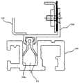
图16为表示乘降门和纵框以及上框的关系的分解放大立体图和局部主视图。Fig. 16 is an exploded enlarged perspective view and a partial front view showing the relationship between the landing door, the vertical frame, and the upper frame.
图17为表示本发明其他实施例的与图15相对应的附图。Fig. 17 is a diagram corresponding to Fig. 15 showing another embodiment of the present invention.
图18为说明现有技术的问题点的附图。Fig. 18 is a diagram illustrating problems of the conventional art.
图19为表示乘降门和纵框以及上框的关系的其他的分解放大立体图和局部主视图。Fig. 19 is another exploded enlarged perspective view and partial front view showing the relationship between the landing door, the vertical frame, and the upper frame.
图20为表示门和上框之间的间隙以及门相互间的间隙的俯视图。Fig. 20 is a plan view showing the gap between the door and the upper frame and the gap between the doors.
图21为表示门和上框之间的间隙的侧视图。Fig. 21 is a side view showing the gap between the door and the upper frame.
图22为说明由支架堵塞了烟的进入通路的侧视图。Fig. 22 is a side view illustrating that the intake passage of smoke is blocked by the holder.
图23为说明由遮蔽材料堵塞了门相互间的间隙的立体图。Fig. 23 is a perspective view illustrating that a gap between doors is blocked by a masking material.
图24为表示本发明的门装置第2实施例的主视图。Fig. 24 is a front view showing a second embodiment of the door apparatus of the present invention.
图25为图24的A-A线向视放大图。Fig. 25 is an enlarged view taken along line A-A of Fig. 24 .
图26为图24的B-B线向视放大图。Fig. 26 is an enlarged view taken along the line B-B in Fig. 24 .
图27为图24的C-C线向视图。Fig. 27 is a view along line C-C of Fig. 24 .
图28为图27的Z部放大图。FIG. 28 is an enlarged view of the Z portion in FIG. 27 .
图29为图27的D-D线向视图。Fig. 29 is a view along the line D-D of Fig. 27 .
图30为图24的E-E线向视图。Fig. 30 is a view along line E-E of Fig. 24 .
图31为图27的F-F线局部向视图。Fig. 31 is a partial view taken along line F-F of Fig. 27 .
图32为表示高速门和上框以及纵框的关系的立体图。Fig. 32 is a perspective view showing the relationship between the high-speed door, an upper frame, and a vertical frame.
图33为图32的俯视图。FIG. 33 is a top view of FIG. 32 .
图34为表示低速门和高速门侧上部和上框的关系的立体图。Fig. 34 is a perspective view showing the relationship between the upper part of the low-speed door and the high-speed door side and the upper frame.
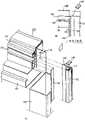
图35为表示低速门和上框以及纵框的关系的立体图和局部放大图。Fig. 35 is a perspective view and a partially enlarged view showing the relationship between the low-speed door, the upper frame, and the vertical frame.
图36为对本实施例的效果加以说明的附图。Fig. 36 is a diagram for explaining the effects of this embodiment.
图37为表示本实施例的其他构成例的附图。Fig. 37 is a diagram showing another configuration example of this embodiment.
图38为本发明的门装置第3实施例中上锁装置的整体图。Fig. 38 is an overall view of the locking device in the third embodiment of the door device of the present invention.
图39为图38的B-B线向视图。Fig. 39 is a view along the line B-B of Fig. 38 .
图40为说明该上锁装置的动作的附图。Fig. 40 is a diagram for explaining the operation of the locking device.
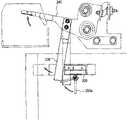
图41为表示本发明的门装置的局部主视图。Fig. 41 is a partial front view showing the door device of the present invention.
图42为图40的左侧视图。FIG. 42 is a left side view of FIG. 40 .
图43为表示门装置的其他实施例的主视图。Fig. 43 is a front view showing another embodiment of the door device.
图44为图33的右侧视图。FIG. 44 is a right side view of FIG. 33 .
图45为表示关门力增强装置的其他构成例的主视图。Fig. 45 is a front view showing another configuration example of the door closing force enhancing device.
图46为表示关门力增强装置的另一构成例的主视图。Fig. 46 is a front view showing another configuration example of the door closing force enhancing device.
图47为表示隔烟机构的剖视图。Fig. 47 is a sectional view showing a smoke blocking mechanism.
图48为表示隔烟机构的上部结构的剖视图。Fig. 48 is a sectional view showing the upper structure of the smoke blocking mechanism.
图49为设置在上部的隔烟部件的剖视图。Fig. 49 is a cross-sectional view of the smoke blocking member provided on the upper part.
图50为表示隔烟机构的下部结构的剖视图。Fig. 50 is a sectional view showing the lower structure of the smoke blocking mechanism.
图51为设置在下部的隔烟部件的剖视图。Fig. 51 is a cross-sectional view of the smoke insulating member provided at the lower part.
具体实施方式Detailed ways
第1实施例first embodiment
以下,参照附图对本发明的电梯用门装置的第1实施例加以说明。Hereinafter, a first embodiment of the elevator door apparatus according to the present invention will be described with reference to the drawings.
在图1中所示的电梯中,包围从乘降场通到升降通路中的开口部地配备有上框103以及左右一对的纵框102、102,同时在该开口部上配备有从中央向两侧打开的左右一对对开的乘降门110、110。门110、110吊在可往返移动地卡合在滑轨4上的一对吊架109、109上。另外,在开口部的下缘上配备有门栏104,门110、110的下端部可滑动地嵌在门栏104中。In the elevator shown in Figure 1, an
图2为表示本实施例的门装置的俯视图,图7为图2中的门装置下部的局部主视图,图8为图7中的门装置上部的局部主视图,图9为图2的P部放大图,图10为图7的Q部放大图,图11为图7的A-A线向视图,图12为图7的B-B线向视图,图13为图7的C-C线向视图,图14为图8的R部放大图,图15为图14的D-D线向视图,图16为表示乘降门110和纵框102的关系的分解放大立体图和局部主视图。Fig. 2 is a top view showing the door device of this embodiment, Fig. 7 is a partial front view of the lower part of the door device in Fig. 2, Fig. 8 is a partial front view of the upper part of the door device in Fig. 7, and Fig. 9 is a P Figure 10 is an enlarged view of the Q part of Figure 7, Figure 11 is a line view of A-A line in Figure 7, Figure 12 is a line view of B-B line in Figure 7, Figure 13 is a line view of C-C line in Figure 7, Figure 14 It is an enlarged view of the R portion in FIG. 8 , FIG. 15 is a D-D line view in FIG. 14 , and FIG. 16 is an exploded enlarged perspective view and a partial front view showing the relationship between the landing
图中,与图3至图6相同的附图标记表示相同的部分。图8中所示的110为吊在门吊架109上的门,110a(图2、图7、图9、图10、图12中的附图标记)为被门栏104的槽104a引导的导块,经由支架110b(图12中的附图标记)安装在门110的底部上。图10和图11中所示的111为例如具备朝向前端扩开的左右一对突片的阻燃性橡胶构成的隔烟材料,经由支架110c嵌合在凹部中而安装在乘降门110的底部上,并设置在导块110a的安装部分之外的部分上。虽然在这种乘降门110中未示出,但众所周知,是始终附与了由重锤产生的关门力的结构。In the drawings, the same reference numerals as those in FIGS. 3 to 6 denote the same parts. 110 shown in Fig. 8 is the door that hangs on the
图10和图13中所示的112、112’为设置在乘降门110的侧部上的具有隔烟材料的作用的橡胶门挡,下垂到下方进入门栏104的槽104a中,即下垂到覆盖隔烟材料111的端部的位置。也就是说,这种橡胶门挡112、112’和隔烟材料111配置成例如位于同一垂直平面上并可接触的状态。这种橡胶门挡112和橡胶门挡112’例如是在一个上形成凹部,而在另一个上形成凸部,从而在乘降门110关闭时相互紧贴在一起而无间隙地接触。112 and 112' shown in Fig. 10 and Fig. 13 are rubber doorstops with the function of smoke-insulating material arranged on the side of the
这种隔烟材料111由于在门开闭时左右一对突片的前端不接触门栏槽104a的侧壁地挠曲,所以在通常的开闭时能够抑制隔烟材料111前端的磨损,在火灾时,火灾室一侧的空气膨胀,含有高压的烟的空气欲通过门的下部而排出,但在空气流入了设置在门的下端上的隔烟材料111内时,由于非火灾室一侧的隔烟材料的突片被推压在门栏槽104a的侧壁上,所以可根据烟的流动方向可靠地确保充分的气密性。在此,乘降门110关闭时,橡胶门挡112、112’和隔烟材料111在关门力的作用下适度接触,从而除了上述的作用和效果之外,还能够堵塞下方的间隙。关于这种隔烟材料111的形状,可以是左右一对突片的前端向内侧稍稍弯曲。另外,在左右的乘降门110关闭后,通过使设置在该乘降门110上的上述隔烟材料111彼此适度接触,能够消除该橡胶门挡112、112’的下垂。Such a
另一方面,图14中所示的113、113’为设置在乘降门110的上端的隔烟材料,与橡胶门挡112、112’相同,在一个上形成凹部,在另一个上形成凸部,能够无间隙地接触,从而乘降门110的关闭时在关门力的作用下严丝合缝地紧贴在一起。而且,通过橡胶门挡112、112’以及配置在与橡胶门挡112、112’相接的位置上的隔烟材料113,在乘降门110关闭时可靠地消除上方的间隙。因此,在乘降门110关闭时的关门力的作用下,不仅堵塞了乘降门110之间的间隙,而且也能够对上部和下部的间隙进行适当的堵塞。关于这种能够无间隙地接触的结构,可考虑仅是凹部和凸部的嵌合之外的各种结构,并不仅限于实施例。On the other hand, 113, 113' shown in FIG. 14 is a smoke-insulating material provided on the upper end of the
而且,图8和图15中所示的120为可自由拆装地嵌入在倾斜地设置在乘降门110的上端的U槽支架114中、例如中空的隔烟材料,倾斜地配置成随着离开纵框102而高度增高。121为可在上下方向上相对于上框103进行自由调整地设置的挡板,安装成在乘降门110关闭时与隔烟材料120接触而堵塞间隙。这种挡板121也倾斜地配置成随着离开纵框102而高度增高。在此,通过配置成左右的乘降门110关闭时,设置在对向的乘降门110上的隔烟材料120彼此接触,能够取消上述的隔烟材料113、113’。Moreover, 120 shown in FIGS. 8 and 15 is a hollow smoke-insulating material that is detachably embedded in the
图16(a)为表示乘降门110和纵框102以及上框103的关系的分解立体放大图,图16(b)为图16(a)的局部主视图。图中,115为设置在乘降门110的侧面上的L字形支架,在该支架115上安装具有隔烟材料130的支架131(隔烟材料130可自由拆装地嵌入支架131上设置的U槽支架132中),通过长孔115a在乘降门110的宽度方向上进行调整,从而安装成隔烟材料120和隔烟材料130在平时相接触。也就是说最好是将隔烟材料120和隔烟材料130配置在相同的垂直平面上。122为向上方延伸地设置在纵框102上的支架,由于上框103覆盖纵框102的上方地放置在纵框102上,所以支架122配置成覆盖上框103的侧面的一部分。140为覆盖该隔烟材料130的上方的罩。在乘降门110关闭时,通过隔烟材料130被压接在支架122的一个面上,乘降门110和纵框102以及上框103的间隙被隔烟材料120和隔烟材料130适当地堵塞。Fig. 16(a) is an exploded perspective enlarged view showing the relationship between the landing
另外,作为其他的实施例,例如也可考虑图19中所示的结构。即,L字形支架115’、支架113’、以及隔烟材料130只到纵框102的高度,因此,通过安装面上贴附了橡胶的L字形支架133(例如隔烟材料120和隔烟材料130配置在同一平面上),同时覆盖上框103的侧面和纵框102的上表面并消除其间隙。In addition, as another example, the structure shown in FIG. 19 is also conceivable, for example. That is, the L-shaped support 115', the support 113', and the smoke-insulating
因此,在左右的乘降门110关闭的情况下,纵框102和乘降门110之间的间隙由隔烟材料130堵塞,上框103和乘降门110之间的间隙由隔烟材料120堵塞,对于乘降门110之间的间隙,由橡胶门挡112、112’堵塞,乘降门110和门栏104之间的间隙由隔烟材料111堵塞,对于乘降门110彼此和门栏104之间的间隙,由隔烟材料111和橡胶门挡112、112’堵塞,对于乘降门110彼此和上框103之间的间隙,由橡胶门挡112、112’和隔烟材料113、113’或者隔烟材料120彼此堵塞,能够可靠地防止烟从乘降场向升降通路流入或从升降通路向乘降场一侧流出。Therefore, when the left and
关于这些隔烟材料120、130以及隔烟材料111,可考虑根据各自的作用、功能、性质等决定其材质或形状。即,在隔烟材料130的情况下,由于仅是表面被挤压的部件,所以仅满足隔烟性能即可,而不必考虑伴随着摩擦的移动。另一方面,在隔烟材料111的情况下,由于随着门的开闭动作,经常相对于门栏104相对运动,所以不仅是隔烟性能,还需要考虑摩擦(振动或噪音对策等),要求也可进行顺畅的滑动动作的功能。另外,在隔烟材料120的情况下,由于在门关闭时还承受因与挡板121的相对运动产生的摩擦,所以虽然不像隔烟材料111那样的程度,但也要求可进行顺畅的滑动动作的功能。即,希望具有隔烟性能和滑动性能双方的性质。Regarding these
在火灾时,尤其是由于气温或气压的变动,所以在因这种气温·气压差的变化而变形的部件、例如隔烟材料120、130的情况下中空部分稍许胀大,或者在隔烟材料111的情况下一对突片沿着烟的流动方向变形是有效的。另外,在隔烟材料的形状根据气压差而变化的情况之外,例如移动自如地构成支承隔烟材料的部件(U槽支架等)也能够获得同样的效果。另外,由于在与隔烟性能有关的规程上要求门两侧的压力差为19.6Pa时漏烟量在0.2m3/min×m2以下即可,而不要求完全隔烟的性能,所以并不需要部件彼此要完全紧贴。In the event of a fire, especially due to changes in air temperature or air pressure, in the case of parts that are deformed due to changes in air temperature and air pressure, such as the
图17为使用了与隔烟材料111相同的部件作为隔烟材料112’的情况。通过尽可能地共用部件,能够相应地抑制部件数量,因而是比较好的。但是,勿庸置疑,可根据对部件所要求的性质·作用·功能适当地选择材质和形状即可。Fig. 17 shows the case where the same member as the
在上述第1实施例中,在图20和图21中所示的上框103和门110之间存在间隙,即使烟从该间隙侵入电梯内,由于通过图16和图19中所示的支架122、133,图22中由阴影线所示的烟的通路被堵塞,所以烟不会向左右泄漏。另外,虽然在两门110、110之间也存在间隙G(约2mm),但由于间隙被图23中所示的隔烟材料113、113’堵塞,所以烟不会向上方泄漏。In the above-mentioned first embodiment, there is a gap between the
另外,根据上述第1实施例,由于在通常的门开闭时产生振动或噪音等的障碍的顾虑很小,若门关闭,则根据当时的状况可靠地堵塞乘降门和出入口框以及门栏之间的间隙,所以无论何时发生火灾,都能够适当地防止烟的侵入。另外,无需设置用于这种隔烟·防烟功能的特别的驱动机构或装置。并具有能够在已设的电梯中添加采用的优点。In addition, according to the above-mentioned first embodiment, since there is little concern about obstacles such as vibration and noise during normal door opening and closing, if the door is closed, the boarding door, doorway frame, and door rail will be reliably blocked according to the current situation. Therefore, whenever a fire occurs, the intrusion of smoke can be properly prevented. In addition, there is no need to provide a special drive mechanism or device for such a smoke-blocking/smoke-preventing function. And it has the advantage of being able to add applications to existing elevators.
第2实施例2nd embodiment
以下,采用附图对本发明的第2实施例加以说明。Hereinafter, a second embodiment of the present invention will be described using the drawings.
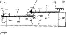
图24为表示本发明的电梯乘降门的一例的主视图,图25为图24的A-A线向视放大图,图26为图24的B-B线向视放大图,图27为图24的C-C线向视图,图28为图27的Z部放大图,图29为图27的D-D线向视图,图30为图24的E-E线向视图,图31为图27的F-F线局部向视图,图32为表示高速门311和上框301以及纵框302的关系的立体图,图33为图32的俯视图,图34为表示低速门312的高速门311一侧上部和上框301的关系的立体图,图35为表示低速门312和上框301以及纵框302的关系的立体图和局部放大图。Figure 24 is a front view showing an example of an elevator landing door of the present invention, Figure 25 is an enlarged view of the A-A line of Figure 24, Figure 26 is an enlarged view of the B-B line of Figure 24, and Figure 27 is a C-C of Figure 24 Line view, Figure 28 is an enlarged view of the Z part of Figure 27, Figure 29 is a D-D line view of Figure 27, Figure 30 is a E-E line view of Figure 24, and Figure 31 is a partial view of the F-F line of Figure 27, Fig. 32 is a perspective view showing the relationship between the high-
图24中所示的311、312为分别吊在门吊架307、308上的单开式乘降门,是高速移动的高速门311和低速移动的低速门312,各自的导块311a、312a分别被图26的门栏305的槽305a、305b引导。在这种乘降门311、312上虽然未图示,但众所周知的是由重锤或弹簧始终附与关门力的结构。在此,关于门312的下方,根据后述的理由而以门311相反一侧的端部的弯曲加工较小的方式构成。311 and 312 shown in Fig. 24 are the single-opening take-off doors hung on the door hangers 307 and 308 respectively, which are the high-
图27和图32中所示的313为设置在门311上与门312相反一侧上的橡胶门挡,314为与该橡胶门挡313对向地设置在纵框302上的橡胶门挡,在这种橡胶门挡313、314的一个上形成凹部,在另一个上形成凸部,以使橡胶门挡彼此严丝合缝地紧贴在一起,具有隔烟作用地能够无间隙接触。关于能够无间隙接触的结构,可考虑仅仅是凹部和凸部的嵌合之外的各种结构,当然并不仅限于实施例。313 shown in FIG. 27 and FIG. 32 is a rubber doorstop arranged on the
图27和图28中所示的315为经由支架315a设置在高速门311的低速门312一侧外表面上的隔烟材料,乘降门关闭时与门312接触而封锁间隙301s。门312的与门311相反一侧的端部的弯曲加工较小(相对于一个的尺寸11,尺寸12为11>12),以使乘降门打开时该隔烟材料315不与门312相接触。即,在门312的左右侧部的厚度上,与门311相反一侧较薄。后述的341为设置在门312的与门311相反一侧外表面上的隔烟材料,在乘降门关闭时与纵框302相接触而封锁间隙302a。315 shown in Fig. 27 and Fig. 28 is the smoke-insulating material provided on the outer surface of the low-
图26中所示的317、318为具备朝向前端扩开的左右一对突片的阻燃性橡胶构成的隔烟材料,以嵌合在门311、312的下端凹部中的方式安装在图24中所示的导块311a、312a的安装部分之外的部位上。这种隔烟材料317、318由于是门开闭时左右一对的突片前端可不接触门栏槽305a、305b的侧壁地挠曲,所以能够抑制在通常的开闭时隔烟材料317、318前端的磨损,在火灾时虽然火灾室一侧的空气膨胀,包含高压的烟的空气欲通过门的下部排出,但在空气流入设置在门的下端的隔烟材料317、318内时,非火灾室一侧的隔烟材料的任一个突片被推压在门栏槽305a、305b的侧壁上,所以根据烟的流动方向可靠地确保了充分的气密性。关于这种隔烟材料317、318的形状,可以是左右一对的突片前端稍稍向内侧弯曲。317 and 318 shown in FIG. 26 are smoke-insulating materials made of flame-retardant rubber with a pair of left and right protrusions that expand toward the front end, and are installed in the recesses of the lower ends of the
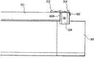
图25中所示的321、322为例如中空的隔烟材料,可自由拆装地嵌入分别倾斜地设置在门311、312的上方的图24的U槽支架323、324中,倾斜地配置成越接近门的关闭一侧越高。而且,特别是U槽支架323和隔烟材料321设置在门312的缺口312b内。325、326为可在上下方向上相对于上框103进行自由调整地设置的挡板,安装成门311、312关闭时与隔烟材料321、322相接触而堵塞间隙303s、304s。这种挡板325、326也如图24所示配置成倾斜状。321 and 322 shown in FIG. 25 are, for example, hollow smoke-insulating materials, which can be freely disassembled and embedded in the
图32中所示的327为堵塞挡板325的端部的平板,328为与该平板327相接触地设置的基座,在基座328上安装有橡胶门挡329。在门311关闭时,虽然橡胶门挡313、314彼此紧贴在一起,但如图33所示,是在门311和纵框302之间朝向上下方向存在间隙303s,该橡胶门挡329覆盖该间隙303s,所以能够适当地堵塞间隙303s的结构。关于这种橡胶门挡329,虽然对使用与上述的橡胶门挡313、314相同的部件的例子进行了描述,但仅是平板也可以。327 shown in FIG. 32 is a flat plate that closes the end of the
图27、图31和图34中所示的330为在门312关闭时堵塞隔烟材料322、挡板326以及U槽支架324的端部的平板,经由L字形的支架331设置在上框301上。图27、图28、图29以及图30中所示的332为具备安装在门311下端侧外表面上支架315a的缺口部上的弹性体的平板,具有门311关闭时堵塞上述隔烟材料315下方的间隙305s的作用。另外,具备与平板332相同的形状·结构的弹性体的平板333也同样地设置在门312下端侧外表面上支架340(后述)的缺口部中,在门312关闭时堵塞后述的隔烟材料341中下方的间隙306a。关于这种平板332、333的形状和结构,可根据当时的情况而改变。而且安装部位也并不仅限于实施例。330 shown in Fig. 27, Fig. 31 and Fig. 34 is a flat plate that blocks the ends of the smoke-insulating
图35中所示的340为设置在门312的侧部外表面上的L字形支架,在该支架340上安装有具有隔烟材料341的支架342(隔烟材料341可自由拆装地嵌入设置在支架342上的U槽支架343中),通过长孔340a在门312的宽度方向上自由调整,并安装成隔烟材料322和隔烟材料341在平时相接触。即,优选地是隔烟材料322和隔烟材料341配置在同一垂直平面上。340 shown in Fig. 35 is an L-shaped support arranged on the side outer surface of the
344为向上方延伸地设置在纵框302上的支架,由于上框301覆盖纵框302地放置在纵框302上,所以支架344配置成覆盖上框301的侧面的一部分。而且,350为覆盖该隔烟材料341的上方的罩。门312关闭时隔烟材料341压接在支架344的一个面上,从而成为门312和纵框302以及上框301之间的间隙307s由隔烟材料322和隔烟材料341适当堵塞的结构。344 is a bracket provided on the
因此,在乘降门311、312关闭的情况下,纵框302和门311之间的间隙由橡胶门挡313和橡胶门挡314以橡胶门挡329堵塞,门312和纵框302之间的间隙由支架344和隔烟材料341堵塞,门311和门312之间的间隙由平板332和隔烟材料315堵塞,上框301和门311之间的间隙由隔烟材料321和挡板325以及橡胶门挡329堵塞,门312和上框301之间的间隙由平板330和隔烟材料322以及挡板326堵塞,门311和门312以及门栏305之间的间隙由隔烟材料317、318以及平板332、333堵塞,能够可靠地防止烟从乘降场向升降通路内流入或从升降通路内向乘降场一侧流出。特别是如图36所示,由于可靠地对三个以上的部件对向的箭头部位中的间隙进行堵塞,所以隔烟效果可以说是万无一失的。Therefore, when the landing
但是,关于这些隔烟材料317、318以及隔烟材料321、322或者隔烟材料315、341,可考虑根据各自的作用·功能·性质等决定材质或形状。即,在隔烟材料315、341的情况下,由于仅是表面被推压的部件,所以仅满足隔烟性能即可,不必特别考虑随着磨擦的动作。另一方面,在隔烟材料317、318的情况下,由于随着门的开闭动作,经常相对于门栏305相对运动,所以不仅是隔烟性能,还需要考虑摩擦(振动或噪音对策等),要求也能进行顺畅的滑动动作的功能。另外,在隔烟材料321、322的情况下,由于在门关闭时还承受因与挡板325、326的相对运动产生的摩擦,所以虽然不像隔烟材料317、318那样的程度,但也要求可进行顺畅的滑动动作的功能。即,希望具有隔烟性能和滑动性能双方的性质。由于在关门的终端部,门311、312是在被推压在挡板325、326上的状态下关闭,从而成为伴随着磨擦的动作,所以在这种隔烟材料321、322上实施以低摩擦系数提高耐磨损性的特殊加工,在挡板325、326一侧贴附滑动特性优良的带等是有效。However, regarding these
在火灾时,尤其是由于气温或气压的变动,所以在因这种气温·气压差的变化而变形的部件、例如隔烟材料321、322、341的情况下中空部分稍许胀大,或者在隔烟材料317、318的情况下左右一对突片沿着烟的流动方向变形是有效的。另外,在隔烟材料的形状根据气压差而变化的情况之外,例如移动自如地构成支承隔烟材料的部件(U槽支架等)也能够获得同样的效果。另外,由于在与隔烟性能有关的规程上要求门两侧的压力差为19.6Pa时漏烟量在0.2m3/min×m2以下即可,而不要求完全隔烟的性能,所以并不需要部件彼此要完全紧贴。In the event of a fire, especially due to changes in air temperature or air pressure, in the case of parts that are deformed due to changes in air temperature and air pressure, such as the
图37为使用了与隔烟材料317、318相同的部件作为隔烟材料321’、322’的情况。通过尽可能地共用部件,能够相应地抑制部件数量,因而是比较好的。但是,勿庸置疑,可根据对部件所要求的性质·作用·功能适当地选择材质和形状即可。Fig. 37 shows the case where the same members as the
根据上述第2实施例,由于在通常的门开闭时产生振动或噪音等的障碍的顾虑很小,若门关闭,则根据当时的状况可靠地堵塞乘降门和出入口框以及门栏之间的间隙,所以无论何时发生火灾,都能够适当地防止烟的侵入。另外,无需设置用于这种隔烟·防烟功能的特别的驱动机构或装置。并具有能够在已设的电梯中添加采用的优点。According to the above-mentioned second embodiment, since there is little concern about obstacles such as vibration and noise during normal door opening and closing, when the door is closed, the gap between the landing door, the doorway frame, and the door rail can be reliably blocked according to the current situation. Therefore, whenever a fire occurs, the intrusion of smoke can be properly prevented. In addition, there is no need to provide a special drive mechanism or device for such a smoke-blocking/smoke-preventing function. And it has the advantage of being able to add applications to existing elevators.
第3实施例3rd embodiment
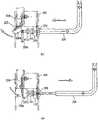
图38为表示本发明的上锁装置一实施例的整体图,图39为图38的B-B线向视图,图40为说明本发明装置的动作的说明图。Fig. 38 is an overall view showing an embodiment of the locking device of the present invention, Fig. 39 is a view along the line B-B of Fig. 38, and Fig. 40 is an explanatory diagram illustrating the operation of the device of the present invention.
图中,201为乘降门,其内部通过螺母212安装有中空部件211。220为在相同的乘降门201的内部面对钥匙孔202地设置的、例如由铰链结构支承的阀,由密封件220a堵塞中空部件211的开口部211a,从而满足隔烟性能。平时由扭簧220b维持在关闭开口部211a的状态。这种中空部件是用于难以因从乘降门210的表面漏出规定的距离而仅用金属丝进行操作的恶作剧防止对策。In the figure, 201 is a landing door, and a
230为操作锁具240的杆件,一端连结在锁具240上,另一端配置在例如中空部件211的下方附近。另一方面,250为本发明的开锁钥匙,例如成L字形,前端部向规定方向自由折曲。在图示的实施例中,开锁钥匙的前端部是向与L字相反的方向自由折曲。230 is a lever for operating the
以下,采用附图对这种装置的开锁动作加以说明。首先,使开锁钥匙250的一片朝向上方,将前端插入钥匙孔202中并推到最里处。这样一来,前端贯穿中空部件211将密封件220a后推,在这种密封件220a克服扭簧220b的弹簧力而如图40(b)所示向后方旋转的同时,开锁钥匙250的前端部例如因自重而向下弯折,转移成下垂的状态。Hereinafter, the unlocking operation of such a device will be described with reference to the accompanying drawings. First, with one piece of the unlocking key 250 facing upward, insert the front end into the
而且,这次是在图38和图40(b)中,将开锁钥匙250朝向上方的一片向身前转动,前端部250a与杆件230相接触,向图38的里侧推压、即如图39所示使杆件230向箭头方向旋转,从而使锁具240向上方旋转而解除锁定。因此,由于有机地联动进行钥匙孔202的打开动作和解除锁定的动作,所以可非常顺畅地进行乘降门的开闭,能够简单地进行救援·保养作业等。另外,由于中空部件211的存在以及与杆件230的配置关系,难以简单地用弯曲的金属件操作金属丝,所以能够防止恶作剧产生的乘降门210的打开动作于未然,但以仅通过阀220直接堵塞乘降门的钥匙孔2的方式构成也可以。And, this time, in Fig. 38 and Fig. 40(b), the unlocking
另外,关于开锁钥匙250的前端部的折曲结构,除了因自重而弯曲之外,也可以是折曲的方向为与阀220的打开方向相方的方向,关于一个杆件230的另一端的配置,也可以不是配置在下方而配置在阀220的打开一侧附近。In addition, regarding the bending structure of the front end of the unlocking
根据上述第3实施例,可通过开闭阀可靠地防止烟的侵入,能够非常好地维持隔烟性能。另外,关于解除乘降门的锁定的作业,能够没有任何障碍地简单进行。According to the above-mentioned third embodiment, the intrusion of smoke can be reliably prevented by the on-off valve, and the smoke-blocking performance can be maintained very well. In addition, the work of unlocking the landing door can be easily performed without any trouble.
第4实施例4th embodiment
在本实施例的门装置中,如图47所示,在门110的下端部以及背面上部分别安装有隔烟部件95、96。上方的隔烟部件96在门9从全闭位置附近移动到全闭位置的过程中,如图48所示在突出设置在上框91上的挡板94上滑动接触,在火灾发生时隔断烟。另外,下方的隔烟部件95如图50所示可滑动地嵌在门栏93的槽中,在火灾发生时隔断烟。In the door apparatus of the present embodiment, as shown in FIG. 47 ,
上方的隔烟部件96是合成树脂制成,与挡板94滑动接触的部分形成为图49所示的截面环状,在其表面上实施了例如硅弹性体等表面活性改性处理剂形成的覆膜96a,因此抑制了因与挡板94的摩擦而产生隔烟部件96的磨损或噪音。The upper smoke-insulating
另外,下方的隔烟部件95是合成树脂制成,与门栏93的滑动接触部分如图51所示形成为朝向下方扩开的截面形状,在其表面上实施了例如聚酯弹性体等表面活性改善处理剂形成的覆膜95a,因此抑止了因与门栏93的摩擦而产生隔烟部件95的磨损或噪音。关于这种隔烟部件96、95的表面加工,只要是易于滑动,耐磨损性优良即可,能够采用其他的各种方法。另外,在隔烟材料96、95的两部件上实施了表面加工,但当然也可以仅在任一个部件上实施表面加工。In addition, the lower
在从乘降场通到升降通路的开口部的上方位置上安装有图41中所示的顶盖3。在此,在顶盖3上水平地设置有滑轨4,在该滑轨4上设置有一对吊架109、109,可沿着滑轨4自由移动。另外,在顶盖3上的两端配置一对皮带轮6、7,两皮带轮6、7上卷绕有金属线5,该金属线的两端连结在一个吊架109上。绕挂在两皮带轮6、7之间的金属线5的中间位置上固定有夹具8,该夹具8连结在另一个吊架109上。因此,两吊架109、109向互为相反的方向移动。The
另外,两皮带轮6、7如图42所示支承在倾斜的姿势,因此实现了空间的有效利用。In addition, since both
如图41所示,在上述另一个吊架109上配备有用于以全开位置锁定门的锁定装置10。另外,在该吊架109和顶盖3之间张设有弹簧11,在该弹簧11的作用下,一对吊架109、109始终向关门方向受力。As shown in FIG. 41, the above-mentioned
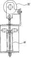
另外,在上述一个吊架109上连接有本发明的关门力增强装置20。在该关门力增强装置20中,在顶盖3上固定有凸轮21。在吊架109上经由支架24枢轴支承有杆件23的中间部,在该杆件23的根端部连结有弹簧25,在该弹簧25的作用下,杆件23始终逆时针方向旋转地受力。在杆件23的前端部上旋转自如地枢轴支承有辊22,该辊22承受弹簧25的施力而压接在凸轮21上。In addition, the door closing
如上所述,由于在一对吊架109、109内的一个吊架109上设置有关门力增强装置20,在另一个吊架109上设置有锁定装置10,所以即使在假设金属线5因火灾等而被切断的情况下,由一个吊架109支承的门也因关门力增强装置20的动作而保持在关闭位置,同时由另一个吊架109支承的门因锁定装置10的动作而不能够通过手动打开。这样一来,由于门保持在关闭状态,所以是安全的。As mentioned above, since the door-closing
另外,在关门力增强装置20上可设置调整关门力增强的大小、或者开始增强的门的位置的调整机构,例如可采用将由辊22以及杆件23构成的辊支承机构的位置上下或水平错位的调整机构、调节弹簧25的初始变形量的调整机构等。因此,能够在现场容易地调整关门力等。In addition, an adjustment mechanism can be provided on the door closing
在图41中,双点划线表示门全开状态下的吊架109、109以及辊22的位置,实线表示门全闭状态下的吊架109、109以及辊22的位置。在从门全开状态转移到门全闭状态的过程中,辊22首先由凸轮21的水平凸轮面引导。在此,由于在辊22上通过弹簧25作用有相对水平凸轮面垂直方向的反作用力,而不产生水平方向的分力,所以门与现有的装置同样地承受弹簧11的施力而向关闭方向被驱动。之后,当转移到门即将全闭的状态之前,辊22压接在凸轮21的倾斜凸轮面上,在该辊22上作用有相对倾斜凸轮面垂直方向的反作用力。由于该反作用力具有水平方向的成分,所以在水平方向的分力的作用下,吊架109向关闭方向受力。因此,在门上同时施加由弹簧11的施力产生的关门力和上述水平方向的分力产生的关门力,关门力被增强。In FIG. 41 , dashed-two dotted lines indicate the positions of
在上述的门装置中,在门从全闭位置附近移动到全闭位置的过程中,特别是从门即将全闭的状态之前开始,上方的隔烟部件96开始与挡板94的滑动接触,阻力影响到门的移动,但由于通过关门力增强装置20,关门力被增强到大于阻力,所以门被完全地关闭。In the above-mentioned door device, when the door moves from the vicinity of the fully closed position to the fully closed position, especially from before the door is fully closed, the upper smoke-insulating
另外,在电梯设置在户外,门的开闭受风的影响很大的情况下,或者由于其他各种理由,在门接近于全闭位置时作用了大的阻力,门也因关门力增强装置20产生的关门力的增强而被完全地关闭。In addition, when the elevator is installed outdoors, the opening and closing of the door is greatly affected by the wind, or due to various other reasons, when the door is close to the fully closed position, a large resistance is applied, and the door is also affected by the closing force enhancement device. 20 resulting in an increase in the closing force to be completely closed.
图43和图44表示门是由从一侧向一个方向打开的两扇门构成的单开式情况的门装置的结构。在该结构中,由于空间比较富裕,所以关门力增强装置20’的一部分配备在具备锁定装置10、悬吊高速一侧的门的吊架109’上。即,凸轮21’设置在顶盖3上,另一方面,经由杆件23’和支架24’安装在吊架109’上,杆件23’的另一端由弹簧25施力。Fig. 43 and Fig. 44 show the structure of the door device in the single-opening case where the door is composed of two doors that open from one side to one direction. In this structure, a part of the door closing force booster 20' is provided on the hanger 109' provided with the locking device 10 and suspending the door on the high-speed side because the space is relatively large. That is, the cam 21' is arranged on the
在该门装置中也与上述的门装置相同,在从门即将全闭的状态转移到门全闭状态的过程中,辊22’压接在凸轮21’的倾斜凸轮面上,关门力因该辊22’承受的水平方向的分力而被增强。In this door device, it is also the same as the above-mentioned door device. In the process of transferring from the state of the door to the fully closed state to the fully closed state of the door, the roller 22' is pressed against the inclined cam surface of the cam 21', and the door closing force is caused by this. The component force in the horizontal direction that the roller 22' receives is strengthened.
另外,图45和图46表示关门力增强装置中辊支承机构其他构成例。在图45的构成例中,将辊32作为施力部件,采用了扭簧31,一端具有辊32的T字形杆件33在扭簧31的作用下顺时针方向旋转地受力。作为将该辊32压接在凸轮21(21’)上的构成,实现了空间的节省。In addition, Fig. 45 and Fig. 46 show other configuration examples of the roller support mechanism in the door closing force enhancing device. In the configuration example of FIG. 45 , the
另一方面,在图46所示的构成例中,省略上述的杆件,通过螺旋状的弹簧对41辊32’施力,使其趋于垂直上方,因此可采用弹性系数小的弹簧41。On the other hand, in the configuration example shown in FIG. 46, the above-mentioned lever is omitted, and the 41 roller 32' is biased vertically upward by a helical spring, so a
如上所述,根据本实施例的门装置,通过在现有的装置中添加简单的结构即可与隔烟机构的装备或周围的环境条件等无关地始终将门可靠地关闭到全闭位置。As described above, according to the door device of this embodiment, the door can always be reliably closed to the fully closed position regardless of the equipment of the smoke blocking mechanism or the surrounding environmental conditions by adding a simple structure to the existing device.
Claims (28)
Applications Claiming Priority (11)
| Application Number | Priority Date | Filing Date | Title |
|---|---|---|---|
| JP136046/2002 | 2002-05-10 | ||
| JP2002136046 | 2002-05-10 | ||
| JP173302/2002 | 2002-06-13 | ||
| JP2002173302AJP4280032B2 (en) | 2002-05-10 | 2002-06-13 | Elevator door device |
| JP2002185695AJP2004026415A (en) | 2002-06-26 | 2002-06-26 | Lock device for elevator landing door |
| JP185695/2002 | 2002-06-26 | ||
| JP242798/2002 | 2002-08-23 | ||
| JP2002242798AJP4280041B2 (en) | 2002-08-23 | 2002-08-23 | Elevator door device |
| JP122557/2003 | 2003-04-25 | ||
| JP2003122557AJP4299573B2 (en) | 2003-04-25 | 2003-04-25 | Elevator door equipment |
| PCT/JP2003/005862WO2003095351A1 (en) | 2002-05-10 | 2003-05-12 | Door device of elevator |
Publications (2)
| Publication Number | Publication Date |
|---|---|
| CN1665738A CN1665738A (en) | 2005-09-07 |
| CN1665738Btrue CN1665738B (en) | 2010-09-29 |
Family
ID=29424809
Family Applications (1)
| Application Number | Title | Priority Date | Filing Date |
|---|---|---|---|
| CN038161923AExpired - Fee RelatedCN1665738B (en) | 2002-05-10 | 2003-05-12 | elevator door device |
Country Status (6)
| Country | Link |
|---|---|
| US (1) | US7510055B2 (en) |
| JP (1) | JP4299573B2 (en) |
| KR (1) | KR100962945B1 (en) |
| CN (1) | CN1665738B (en) |
| AU (1) | AU2003235930A1 (en) |
| WO (1) | WO2003095351A1 (en) |
Cited By (1)
| Publication number | Priority date | Publication date | Assignee | Title |
|---|---|---|---|---|
| TWI600605B (en)* | 2016-12-22 | 2017-10-01 | 國揚電梯工業股份有限公司 | Elevator door with fire and smoke prevention mechanism |
Families Citing this family (21)
| Publication number | Priority date | Publication date | Assignee | Title |
|---|---|---|---|---|
| US7788854B2 (en)* | 2002-09-03 | 2010-09-07 | Harold S. Friedman | Elevator entrance door sill pivotable into and out of elevator shaft via hinge connected support and alignment brackets |
| JP4322579B2 (en)* | 2003-07-28 | 2009-09-02 | 東芝エレベータ株式会社 | Elevator door sealing device |
| US20100083581A1 (en)* | 2007-06-18 | 2010-04-08 | Mattice Douglas A | Environmental brush seal |
| US8653982B2 (en) | 2009-07-21 | 2014-02-18 | Openings | Door monitoring system |
| NZ625983A (en)* | 2009-11-27 | 2016-02-26 | Adverio Pharma Gmbh | Method for producing methyl-{ 4,6-diamino-2-[1-(2-fluorobenzyl)-1h-pyrazolo[3,4-b]pyridino-3-yl]pyrimidino-5-yl} methyl carbamate and its purification for use thereof as pharmaceutical substance |
| JP5953650B2 (en)* | 2011-03-10 | 2016-07-20 | フジテック株式会社 | Door device equipped with a door closing force enhancing device |
| JP5765164B2 (en)* | 2011-09-28 | 2015-08-19 | フジテック株式会社 | Elevator door equipment |
| GB2506628B (en)* | 2012-10-04 | 2015-03-11 | Isolux Ssl Ltd | Locking mechanism for a door of an elevator shaft |
| WO2014207896A1 (en)* | 2013-06-28 | 2014-12-31 | 三菱電機株式会社 | Elevator car |
| JP6229943B2 (en)* | 2014-03-05 | 2017-11-15 | フジテック株式会社 | Elevator door opening and closing device |
| JP6335134B2 (en)* | 2015-03-30 | 2018-05-30 | 株式会社日立製作所 | Elevator equipment |
| JP6339516B2 (en)* | 2015-03-30 | 2018-06-06 | 株式会社日立製作所 | Elevator equipment |
| EP3088344B1 (en)* | 2015-04-28 | 2017-04-26 | Kone Corporation | Elevator landing door leaf |
| CN107473061B (en)* | 2016-06-08 | 2020-10-16 | 奥的斯电梯公司 | Maintenance safety device for elevator system and operation method thereof |
| CN110697537A (en)* | 2018-07-09 | 2020-01-17 | 松山特殊电梯有限公司 | Emergency elevator |
| US10858220B2 (en)* | 2019-02-26 | 2020-12-08 | Td Ip Holdco, Llc | Surface mounted door frame |
| DE102019211973A1 (en)* | 2019-08-09 | 2021-02-11 | Thyssenkrupp Elevator Innovation And Operations Ag | Safety device for an elevator car that moves in a horizontal direction |
| US11873192B2 (en)* | 2020-03-30 | 2024-01-16 | Mitsubishi Electric Corporation | Elevator door control system |
| USD957923S1 (en)* | 2020-04-20 | 2022-07-19 | Daniel Lance | Universal door adapter |
| JP7171851B1 (en)* | 2021-08-03 | 2022-11-15 | 東芝エレベータ株式会社 | elevator landing equipment |
| CN115535810A (en)* | 2022-09-06 | 2022-12-30 | 上海三菱电梯有限公司 | Elevator fire protection landing door device |
Citations (4)
| Publication number | Priority date | Publication date | Assignee | Title |
|---|---|---|---|---|
| US4058191A (en)* | 1976-10-06 | 1977-11-15 | Westinghouse Electric Corporation | Elevator system including an elevator car having door operated sealing devices adjacent door opening |
| WO1998022381A1 (en)* | 1996-11-18 | 1998-05-28 | Allen Thomas H | Elevator hoistway door seal structure and drainage system for a multiple level building |
| US5794745A (en)* | 1995-03-16 | 1998-08-18 | Kleeneze Sealtech Limited | Finger guard for a door of an elevator |
| US5936424A (en)* | 1996-02-02 | 1999-08-10 | Xilinx, Inc. | High speed bus with tree structure for selecting bus driver |
Family Cites Families (33)
| Publication number | Priority date | Publication date | Assignee | Title |
|---|---|---|---|---|
| US1406951A (en)* | 1920-10-23 | 1922-02-14 | Fehr Frank | Elevator-hatchway seal |
| US3024504A (en)* | 1959-10-02 | 1962-03-13 | Wallace W Miller | Sealing means for swinging doors and windows |
| US3504456A (en)* | 1969-01-16 | 1970-04-07 | Steelcraft Mfg Co | Adjustable weather sealing rail for doors |
| JPS5123829B2 (en) | 1973-11-14 | 1976-07-20 | ||
| JPS5415401Y2 (en)* | 1973-11-22 | 1979-06-21 | ||
| JPS5449066U (en)* | 1977-09-13 | 1979-04-05 | ||
| JPS5449066A (en) | 1977-09-27 | 1979-04-18 | Nec Corp | Semiconductor device |
| WO1986003131A1 (en)* | 1984-11-27 | 1986-06-05 | Howa Co., Ltd | Self-closing door sealing structure |
| JPS6247588A (en) | 1985-08-28 | 1987-03-02 | 財団法人 電力中央研究所 | Nuclear reactor |
| JPS6247588U (en)* | 1985-09-11 | 1987-03-24 | ||
| JPS63112389A (en)* | 1986-10-30 | 1988-05-17 | 三菱電機株式会社 | Smoke-proof device for elevator |
| JPH0626530Y2 (en)* | 1987-05-30 | 1994-07-20 | 株式会社東芝 | Sliding door device for elevator |
| ES2046616T3 (en) | 1989-09-22 | 1994-02-01 | Inventio Ag | ACOUSTIC INSULATION OF ELEVATOR CABIN DOORS. |
| JP2502180B2 (en)* | 1990-10-01 | 1996-05-29 | 三菱電機株式会社 | Elevator hall device |
| JP2674424B2 (en)* | 1992-06-10 | 1997-11-12 | 三菱電機株式会社 | Smoke-proof door device for elevator |
| JPH0626530A (en) | 1992-06-23 | 1994-02-01 | Aisin Chem Co Ltd | Method for polishing clutch plate |
| JP3121683B2 (en) | 1992-06-30 | 2001-01-09 | 日本化薬株式会社 | Aromatic indoor mite repellent |
| JPH0616515U (en)* | 1992-07-31 | 1994-03-04 | 東芝モノフラックス株式会社 | Fireproof structure of elevator shaft |
| JP2715828B2 (en) | 1992-08-28 | 1998-02-18 | 三菱電機株式会社 | Elevator doorway device |
| JPH06234488A (en)* | 1993-02-08 | 1994-08-23 | Toshiba Corp | Elevator doorway equipment |
| JPH06345366A (en) | 1993-06-07 | 1994-12-20 | Hitachi Building Syst Eng & Service Co Ltd | Floor door device for elevator |
| JP2878934B2 (en)* | 1993-07-16 | 1999-04-05 | 株式会社東芝 | Elevator door equipment |
| US5377784A (en)* | 1993-09-08 | 1995-01-03 | The Peelle Company | Pass door fire lintel |
| JP3089141B2 (en)* | 1993-09-08 | 2000-09-18 | 株式会社東芝 | Elevator door equipment |
| JPH07206345A (en)* | 1994-01-18 | 1995-08-08 | Hitachi Building Syst Eng & Service Co Ltd | Elevator doorway equipment |
| JPH08127485A (en)* | 1994-11-01 | 1996-05-21 | Otis Elevator Co | Soundproof type elevator cage |
| JP2842516B2 (en)* | 1994-12-12 | 1999-01-06 | 三菱電機株式会社 | Elevator entrance and exit smoke suppressors |
| JPH08239185A (en)* | 1995-03-02 | 1996-09-17 | Toshiba Corp | Elevator entrance / exit |
| JPH08259153A (en) | 1995-03-24 | 1996-10-08 | Otis Elevator Co | Device for holding door closed in elevator |
| EP0821653B1 (en) | 1995-04-18 | 2000-12-27 | ALLEN, Thomas H. | Hoistway door seal structure |
| JP2004196451A (en)* | 2002-12-17 | 2004-07-15 | Hitachi Building Systems Co Ltd | Elevator equipment |
| JP2004323222A (en)* | 2003-04-28 | 2004-11-18 | Mitsubishi Electric Corp | Elevator door equipment |
| WO2005030629A1 (en)* | 2003-09-30 | 2005-04-07 | Toshiba Elevator Kabushiki Kaisha | Disaster control device for elevator |
- 2003
- 2003-04-25JPJP2003122557Apatent/JP4299573B2/ennot_activeExpired - Fee Related
- 2003-05-12WOPCT/JP2003/005862patent/WO2003095351A1/enactiveApplication Filing
- 2003-05-12CNCN038161923Apatent/CN1665738B/ennot_activeExpired - Fee Related
- 2003-05-12AUAU2003235930Apatent/AU2003235930A1/ennot_activeAbandoned
- 2003-05-12KRKR1020047018032Apatent/KR100962945B1/ennot_activeExpired - Fee Related
- 2003-05-12USUS10/513,329patent/US7510055B2/ennot_activeExpired - Fee Related
Patent Citations (4)
| Publication number | Priority date | Publication date | Assignee | Title |
|---|---|---|---|---|
| US4058191A (en)* | 1976-10-06 | 1977-11-15 | Westinghouse Electric Corporation | Elevator system including an elevator car having door operated sealing devices adjacent door opening |
| US5794745A (en)* | 1995-03-16 | 1998-08-18 | Kleeneze Sealtech Limited | Finger guard for a door of an elevator |
| US5936424A (en)* | 1996-02-02 | 1999-08-10 | Xilinx, Inc. | High speed bus with tree structure for selecting bus driver |
| WO1998022381A1 (en)* | 1996-11-18 | 1998-05-28 | Allen Thomas H | Elevator hoistway door seal structure and drainage system for a multiple level building |
Non-Patent Citations (1)
| Title |
|---|
| 同上. |
Cited By (1)
| Publication number | Priority date | Publication date | Assignee | Title |
|---|---|---|---|---|
| TWI600605B (en)* | 2016-12-22 | 2017-10-01 | 國揚電梯工業股份有限公司 | Elevator door with fire and smoke prevention mechanism |
Also Published As
| Publication number | Publication date |
|---|---|
| KR20050023255A (en) | 2005-03-09 |
| CN1665738A (en) | 2005-09-07 |
| AU2003235930A8 (en) | 2003-11-11 |
| US7510055B2 (en) | 2009-03-31 |
| AU2003235930A1 (en) | 2003-11-11 |
| US20060175147A1 (en) | 2006-08-10 |
| KR100962945B1 (en) | 2010-06-09 |
| HK1080441A1 (en) | 2006-04-28 |
| JP2004323204A (en) | 2004-11-18 |
| WO2003095351A1 (en) | 2003-11-20 |
| JP4299573B2 (en) | 2009-07-22 |
Similar Documents
| Publication | Publication Date | Title |
|---|---|---|
| CN1665738B (en) | elevator door device | |
| KR900004810B1 (en) | Self-closing door sealing structure | |
| JP4727072B2 (en) | Elevator hall sliding door device | |
| JP4322579B2 (en) | Elevator door sealing device | |
| JP4280032B2 (en) | Elevator door device | |
| KR100686662B1 (en) | Elevator platform door with flame arresters | |
| CN100379674C (en) | Elevator door device | |
| JP5937255B1 (en) | Elevator equipment | |
| JP4280041B2 (en) | Elevator door device | |
| JP2004196451A (en) | Elevator equipment | |
| JP2004196451A6 (en) | Elevator equipment | |
| JP3789180B2 (en) | Movable communication passage | |
| HK1080441B (en) | Door device of elevator | |
| JP2002371766A (en) | Self-closing sliding fire door device with smoke-blocking function | |
| JP2525343B2 (en) | Elevator door device | |
| JP3782766B2 (en) | Elevator landing equipment | |
| JP4693233B2 (en) | Elevator sliding door device | |
| JP2012162370A (en) | Elevator boarding place door device | |
| JP2004155582A (en) | Elevator doorway device for base-isolated building | |
| JPH08312262A (en) | Device for guiding lower part of fireproof door | |
| JP4445333B2 (en) | Elevator door equipment | |
| JP2005075594A (en) | Elevator entrance device | |
| JP2005200139A (en) | Door device of elevator | |
| KR20220107379A (en) | non mode Window | |
| JP2004083245A (en) | Elevator system |
Legal Events
| Date | Code | Title | Description |
|---|---|---|---|
| C06 | Publication | ||
| PB01 | Publication | ||
| C10 | Entry into substantive examination | ||
| SE01 | Entry into force of request for substantive examination | ||
| REG | Reference to a national code | Ref country code:HK Ref legal event code:DE Ref document number:1080441 Country of ref document:HK | |
| C14 | Grant of patent or utility model | ||
| GR01 | Patent grant | ||
| REG | Reference to a national code | Ref country code:HK Ref legal event code:GR Ref document number:1080441 Country of ref document:HK | |
| CF01 | Termination of patent right due to non-payment of annual fee | Granted publication date:20100929 Termination date:20170512 | |
| CF01 | Termination of patent right due to non-payment of annual fee |