CN1662311B - Method and apparatus for sorting particles - Google Patents
Method and apparatus for sorting particlesDownload PDFInfo
- Publication number
- CN1662311B CN1662311BCN03814212.0ACN03814212ACN1662311BCN 1662311 BCN1662311 BCN 1662311BCN 03814212 ACN03814212 ACN 03814212ACN 1662311 BCN1662311 BCN 1662311B
- Authority
- CN
- China
- Prior art keywords
- particle
- predetermined properties
- actuator
- outlet
- categorizing system
- Prior art date
- Legal status (The legal status is an assumption and is not a legal conclusion. Google has not performed a legal analysis and makes no representation as to the accuracy of the status listed.)
- Expired - Lifetime
Links
Images


Classifications
- B—PERFORMING OPERATIONS; TRANSPORTING
- B07—SEPARATING SOLIDS FROM SOLIDS; SORTING
- B07C—POSTAL SORTING; SORTING INDIVIDUAL ARTICLES, OR BULK MATERIAL FIT TO BE SORTED PIECE-MEAL, e.g. BY PICKING
- B07C5/00—Sorting according to a characteristic or feature of the articles or material being sorted, e.g. by control effected by devices which detect or measure such characteristic or feature; Sorting by manually actuated devices, e.g. switches
- B07C5/34—Sorting according to other particular properties
- B—PERFORMING OPERATIONS; TRANSPORTING
- B03—SEPARATION OF SOLID MATERIALS USING LIQUIDS OR USING PNEUMATIC TABLES OR JIGS; MAGNETIC OR ELECTROSTATIC SEPARATION OF SOLID MATERIALS FROM SOLID MATERIALS OR FLUIDS; SEPARATION BY HIGH-VOLTAGE ELECTRIC FIELDS
- B03B—SEPARATING SOLID MATERIALS USING LIQUIDS OR USING PNEUMATIC TABLES OR JIGS
- B03B5/00—Washing granular, powdered or lumpy materials; Wet separating
- B03B5/02—Washing granular, powdered or lumpy materials; Wet separating using shaken, pulsated or stirred beds as the principal means of separation
- B03B5/10—Washing granular, powdered or lumpy materials; Wet separating using shaken, pulsated or stirred beds as the principal means of separation on jigs
- B03B5/22—Washing granular, powdered or lumpy materials; Wet separating using shaken, pulsated or stirred beds as the principal means of separation on jigs using pulses generated by liquid injection
- G—PHYSICS
- G01—MEASURING; TESTING
- G01N—INVESTIGATING OR ANALYSING MATERIALS BY DETERMINING THEIR CHEMICAL OR PHYSICAL PROPERTIES
- G01N15/00—Investigating characteristics of particles; Investigating permeability, pore-volume or surface-area of porous materials
- G01N15/10—Investigating individual particles
- G01N15/14—Optical investigation techniques, e.g. flow cytometry
- B—PERFORMING OPERATIONS; TRANSPORTING
- B01—PHYSICAL OR CHEMICAL PROCESSES OR APPARATUS IN GENERAL
- B01L—CHEMICAL OR PHYSICAL LABORATORY APPARATUS FOR GENERAL USE
- B01L3/00—Containers or dishes for laboratory use, e.g. laboratory glassware; Droppers
- B01L3/50—Containers for the purpose of retaining a material to be analysed, e.g. test tubes
- B01L3/502—Containers for the purpose of retaining a material to be analysed, e.g. test tubes with fluid transport, e.g. in multi-compartment structures
- B01L3/5027—Containers for the purpose of retaining a material to be analysed, e.g. test tubes with fluid transport, e.g. in multi-compartment structures by integrated microfluidic structures, i.e. dimensions of channels and chambers are such that surface tension forces are important, e.g. lab-on-a-chip
- G—PHYSICS
- G01—MEASURING; TESTING
- G01N—INVESTIGATING OR ANALYSING MATERIALS BY DETERMINING THEIR CHEMICAL OR PHYSICAL PROPERTIES
- G01N15/00—Investigating characteristics of particles; Investigating permeability, pore-volume or surface-area of porous materials
- G01N15/10—Investigating individual particles
- G01N15/14—Optical investigation techniques, e.g. flow cytometry
- G01N15/149—Optical investigation techniques, e.g. flow cytometry specially adapted for sorting particles, e.g. by their size or optical properties
- G—PHYSICS
- G01—MEASURING; TESTING
- G01N—INVESTIGATING OR ANALYSING MATERIALS BY DETERMINING THEIR CHEMICAL OR PHYSICAL PROPERTIES
- G01N15/00—Investigating characteristics of particles; Investigating permeability, pore-volume or surface-area of porous materials
- G01N15/10—Investigating individual particles
- G01N15/14—Optical investigation techniques, e.g. flow cytometry
- G01N2015/1477—Multiparameters
- G—PHYSICS
- G01—MEASURING; TESTING
- G01N—INVESTIGATING OR ANALYSING MATERIALS BY DETERMINING THEIR CHEMICAL OR PHYSICAL PROPERTIES
- G01N15/00—Investigating characteristics of particles; Investigating permeability, pore-volume or surface-area of porous materials
- G01N15/10—Investigating individual particles
- G01N15/14—Optical investigation techniques, e.g. flow cytometry
- G01N2015/1497—Particle shape
Landscapes
- Chemical & Material Sciences (AREA)
- General Physics & Mathematics (AREA)
- Pathology (AREA)
- Health & Medical Sciences (AREA)
- Life Sciences & Earth Sciences (AREA)
- Analytical Chemistry (AREA)
- Biochemistry (AREA)
- General Health & Medical Sciences (AREA)
- Dispersion Chemistry (AREA)
- Physics & Mathematics (AREA)
- Immunology (AREA)
- Separation Of Solids By Using Liquids Or Pneumatic Power (AREA)
- Investigating Or Analysing Biological Materials (AREA)
- Sampling And Sample Adjustment (AREA)
- Automatic Analysis And Handling Materials Therefor (AREA)
- Physical Or Chemical Processes And Apparatus (AREA)
- Investigating Or Analysing Materials By Optical Means (AREA)
- Apparatus Associated With Microorganisms And Enzymes (AREA)
Abstract
Translated fromChineseDescription
Translated fromChinese相关申请related application
本申请要求下列申请的优先权,2002年4月17日申请的美国临时专利申请60/373256,2002年6月24日申请的美国专利申请10/179586,2002年9月16日申请的美国临时专利申请60/411058,2002年12月23日申请的美国专利申请10/329008,并且本申请是2002年6月24日申请的美国专利申请10/179488的部分延续,其内容被并入作为参考。This application claims priority to U.S.
技术领域technical field
本发明涉及对悬浮液中的颗粒进行分类的方法和设备,其中分类组件的输入流路径能分成几个输出通道,更具体地,本发明涉及一种颗粒分类系统,其中多个分类组件互相连接以便获得增加的颗粒通过量。The present invention relates to a method and apparatus for classifying particles in a suspension, wherein the input flow path of the classifying assembly can be divided into several output channels, and more particularly, the present invention relates to a particle classifying system in which a plurality of classifying assemblies are interconnected In order to obtain increased particle throughput.
背景技术Background technique
在生物工程技术领域,特别是细胞学和药品筛选领域,需要颗粒的高通过量分类。需要分类的颗粒的例子是各种类型的细胞,例如血小板、白血球、肿瘤细胞、胚细胞等等,在细胞学领域中人们对这些颗粒特别感兴趣。其它颗粒是(大)分子类的,例如蛋白质、酶类和多核苷酸,在新药品研制期间,在药品筛选领域中人们对这个颗粒家族特别感兴趣。In the field of biotechnology, especially cytology and drug screening, high-throughput sorting of particles is required. Examples of particles to be sorted are various types of cells, such as platelets, leukocytes, tumor cells, blast cells, etc., which are of particular interest in the field of cytology. Other particles are of the (macro)molecular class, eg proteins, enzymes and polynucleotides, this family of particles is of particular interest in the field of drug screening during the development of new drugs.
颗粒分类的方法和设备是已知的,现有技术中描述的大多数都在这样一种条件下工作,即颗粒悬浮在流过通道网络的液体中并根据检测决定偏移的原理工作,所述通道网络在下游具有至少一个分支点。首先分析移动颗粒的特定特性,例如光吸收、荧光强度、尺寸等等,依据该检测阶段的结果,决定在下游怎样对颗粒进行进一步处理,然后,应用决定的结果以将特定颗粒的方向朝着通道网络的预定分支偏移。Methods and devices for particle classification are known and most of those described in the prior art work under conditions where particles are suspended in a liquid flowing through a network of channels and work on the principle that detection determines deflection, so The channel network has at least one branch point downstream. Specific properties of moving particles are first analyzed, such as light absorption, fluorescence intensity, size, etc. Based on the results of this detection stage, a decision is made on how to further process the particle downstream, and the results of the decision are then applied to orient the particular particle towards The predetermined branch offset of the channel network.
重要的是分类设备的通过量,即,每单位时间能分类多少颗粒。对于单独的分类单元,在封闭通道中利用颗粒悬浮流的分类器的通常分类速度处于每秒几百个颗粒到每秒几千个颗粒的范围中。What matters is the throughput of the sorting device, ie how many particles can be sorted per unit of time. Typical sorting speeds for classifiers utilizing particle suspension flow in closed channels are in the range of a few hundred particles per second to thousands of particles per second for individual sorting units.
在美国专利4175662中描述了一种分类设备的例子,其内容在此并入作为参考(在下文中称为‘662专利)。在‘662专利中,在该情况下是细胞的颗粒流流过笔直通道的中央,笔直通道在一下游的分支点分支成两个垂直通道(T形分支),进入的颗粒被兼容液体护层环绕,使颗粒保持被封闭在通道的中央。在正常情况下,对通过两个分支的流量比进行调节以便颗粒自动流过分支之一,在通道的一个部分中,用检测器确定颗粒特性,检测器可以是光学系统(检测阶段)。在决定阶段中,当检测器检测到拥有预定特性的颗粒时,检测器产生一个信号。在偏移阶段,一旦颗粒被检测到,就致动一偏移器以使颗粒偏移。在该例子中,偏移器包括位于通道分支中的电极对,颗粒通常在偏移器的非致动状态中流过所述通道。通过电流脉冲的应用,水成液被电解,产生在电极对之间放出的气泡。由于气泡尺寸增大,在放出气泡阶段期间通过该分支的流量减小。在应用电流脉冲之后,气泡增长停止,气泡与液流一起被携带,结果,通过特定分支的液流瞬间减小,感兴趣的颗粒改变路径并沿着另一个分支流动。An example of a sorting device is described in US Patent 4,175,662, the contents of which are incorporated herein by reference (hereinafter referred to as the '662 patent). In the '662 patent, the stream of particles, in this case cells, flows through the center of a straight channel that branches into two vertical channels (T-branches) at a downstream branch point, and the incoming particles are shielded by a compatible liquid sheath. surround so that the particle remains enclosed in the center of the channel. Normally, the flow ratio through the two branches is adjusted so that the particles automatically flow through one of the branches, and in one part of the channel the particle properties are determined with a detector, which may be an optical system (detection stage). In the decision phase, the detector generates a signal when it detects a particle with predetermined characteristics. In the deflection phase, once a particle is detected, a deflector is actuated to deflect the particle. In this example, the deviator comprises a pair of electrodes located in a branch of a channel through which particles normally flow in the deviator's non-actuated state. By the application of current pulses, the aqueous liquid is electrolyzed, generating gas bubbles that are released between the electrode pairs. Due to the increased size of the bubbles, the flow through this branch decreases during the blebbing phase. After application of a current pulse, bubble growth ceases, the bubbles are entrained with the flow, and as a result, the flow through a particular branch momentarily decreases and the particle of interest changes course and flows along the other branch.
‘662专利的装置对于分类颗粒是有效的,然而,一个严重的缺点是产生了可能堆积在流体网络的某些点处的气泡,该气泡生成可能阻塞流动通道,产生错误的分类。另一个缺点是产生的气体(主要是氧气和氢气)和离子种类(主要是OH-和H+)影响了流过具有电极对的分支的颗粒。另外,细胞和例如酶类的细微蛋白质是非常脆弱的,可能被与气泡一起产生的污垢成分破坏。另一个缺点是整个分类设备的复杂性,具体地说,微电极构造对于在系统的细小通道中安装和装配是非常复杂的,结果,分类单元的成本相对较大。The device of the '662 patent is effective for sorting particles, however, a serious disadvantage is the generation of air bubbles that can accumulate at certain points in the fluid network, which bubble generation can block the flow channels, resulting in misclassification. Another disadvantage is that the generated gases (mainly oxygen and hydrogen) and ion species (mainly OH- and H+ ) affect the particles flowing through the branch with the electrode pair. In addition, cells and fine proteins such as enzymes are very fragile and may be damaged by fouling components generated together with air bubbles. Another disadvantage is the complexity of the whole sorting device, in particular the microelectrode configuration is very complicated to install and assemble in the small channels of the system, and as a result, the cost of the sorting unit is relatively large.
在US 3984307中披露了现有技术的颗粒分类系统的另一个例子,其内容在此并入作为参考(在下文中称为‘307专利)。在‘307专利中,颗粒正在流过通道中央,被流动的护层液体封闭。在经过检测器部分之后,通道分支成两个其间形成锐角的通道(例如Y形分支),就在分支点之前,一个电致动的换能器位于通道中用来偏移具有合适的、预定特性的特定颗粒,描述的换能器是压电式致动器或超声换能器,其在电激励时在通道中产生压力波,产生的压力波立刻扰乱一个分支中的流动,从而将感兴趣的颗粒偏移到另一个分支中。Another example of a prior art particle classification system is disclosed in US 3984307, the contents of which are hereby incorporated by reference (hereinafter referred to as the '307 patent). In the '307 patent, particles are flowing through the center of the channel, enclosed by the flowing sheath liquid. After passing the detector section, the channel branches into two channels forming an acute angle therebetween (for example, a Y-shaped branch), and just before the point of branching, an electrically actuated transducer is located in the channel to deflect the channel with a suitable, predetermined Specific particles of characteristic, the transducers described are piezoelectric actuators or ultrasonic transducers, which, when electrically excited, generate pressure waves in the channel, the generated pressure waves immediately disturb the flow in one branch, thereby placing the sensed Particles of interest migrate into another branch.
在‘307专利的装置中,如同前述装置中,偏移器结合到通道系统内,导致相对大的构造成本。该装置的另一个缺点是所用的偏移器原理,产生的压力波不局限于分支点,而是向上游传播到检测器部分中,以及向下传播到两个分支中,这影响通过通道的整个流动,如果该类型的分类器串联连接或并联连接,这两种连接通常被采用以构造高通过量的分类系统,则这尤其是一个缺点,那时,在一个分类器中产生的压力波能在相邻的分类器单元中影响流动和颗粒的偏移。In the device of the '307 patent, as in the previous devices, the deflector is incorporated into the channel system, resulting in relatively large construction costs. Another disadvantage of this device is the principle of the deflector used, the pressure wave generated is not confined to the branch point, but propagates upstream into the detector section and down into both branches, which affects the flow through the channel This is especially a disadvantage if the classifiers of this type are connected in series or in parallel, which are usually used to construct high-throughput classification systems, when the pressure waves generated in one classifier Ability to influence flow and particle deflection in adjacent classifier units.
在美国专利4756427中披露了另一种分类器,其内容在此并入作为参考。该分类器与‘662专利中的分类器类似,然而,在该例子中,一个分支中的液流由于瞬间改变分支阻力而受到干扰,阻力由于外部致动器改变分支通道的高度而被改变。在优选实施方式中,该外部致动器是粘合在通道顶部上的压电盘,在触发时其使得通道向下移动。Another classifier is disclosed in US Patent 4,756,427, the contents of which are incorporated herein by reference. This classifier is similar to that of the '662 patent, however, in this example, flow in one branch is disturbed by momentarily changing branch resistance, which is changed by an external actuator changing the height of the branch channel. In a preferred embodiment, the external actuator is a piezo disc glued on top of the channel which when triggered moves the channel down.
虽然在‘427专利中描述的分类器构造没有前述分类器结构复杂,但将多个所述类型的分类器组件结合在一起来增加分类速度仍是有问题的,如同‘307专利所述的分类器中一样,这是因为产生的压力波对其它分类器组件造成干涉。While the classifier architecture described in the '427 patent is less complex than the aforementioned classifier architectures, it is still problematic to combine multiple classifier components of the type described to increase the speed of classification, as in the classifier described in the '307 patent. As in the classifier, this is because the generated pressure waves interfere with other sorter components.
在美国专利5837200中披露了另一个颗粒分类设备,其内容在此并入作为参考。‘200专利描述了一种分类设备,其基于颗粒的磁性质,用磁偏移组件来分类或选择颗粒,‘200专利还描述了并行处理和分离单个的颗粒流。Another particle sorting apparatus is disclosed in US Pat. No. 5,837,200, the contents of which are incorporated herein by reference. The '200 patent describes a sorting apparatus that uses a magnetic offset assembly to sort or select particles based on their magnetic properties, and the '200 patent also describes processing and separating individual streams of particles in parallel.
发明内容Contents of the invention
本发明提供了一种给移动经过毛细管大小的封闭通道系统的颗粒进行分类的方法和设备,本发明的颗粒分类系统提供了一种分类组件,其能以低成本装配,同时提供了一种在每时间单位分类大量颗粒的精密手段。颗粒分类系统可以包括多个紧密结合的分类组件,它们被组合起来以进一步增加分类速度。为了降低出错率,颗粒分类系统可以包括多级分类设备以连续给颗粒流分类。The present invention provides a method and apparatus for sorting particles moving through a capillary-sized closed channel system. The particle sorting system of the present invention provides a sorting assembly that can be assembled at low cost while providing an Sophisticated means of sorting large numbers of particles per time unit. Particle sorting systems can include multiple cohesive sorting components that are combined to further increase sorting speed. In order to reduce the error rate, the particle sorting system may include multi-stage sorting equipment to continuously sort the particle stream.
颗粒分类系统实施根据本发明的改进的流体颗粒开关方法和开关装置,颗粒分类系统包括用来分类颗粒的毛细管大小的封闭通道系统,通道系统包括用来引入颗粒流的第一供给管道和用来供应载液的第二供给管道,第一供给管道形成一喷嘴以将颗粒流引入载液的流动中,第一供给管道和第二供给管道与测量管道流体连通,测量管道在一个分支点分支成第一分支和第二分支,测量区域限定在测量管道中并与检测器相关联以在测量区域中检测颗粒的预定特性,两个相对的气泡阀定位成与测量管道并且彼此相对隔开,气泡阀通过一对相对的侧通路与测量管道连通,允许液体部分地填充这些侧通路以在其中形成弯液面,该弯液面作为载液与气泡阀的贮存器的分界。还提供了外部致动器以致动气泡阀中的一个,当外部致动器致动时,致动的气泡阀的贮存器中的压力增加,使弯液面偏移,在测量管道中引起流动扰动以偏移其中的液流。A particle sorting system implementing an improved fluid particle switching method and switching device according to the present invention, the particle sorting system comprising a capillary-sized closed channel system for sorting particles, the channel system comprising a first supply conduit for introducing a flow of particles and a A second supply conduit for supplying the carrier liquid, the first supply conduit forms a nozzle to introduce the flow of particles into the flow of the carrier liquid, the first supply conduit and the second supply conduit are in fluid communication with the measuring conduit, the measuring conduit branches at a branch point into A first branch and a second branch, the measurement area is defined in the measurement pipe and is associated with a detector to detect a predetermined characteristic of the particle in the measurement area, two opposite bubble valves are positioned spaced from the measurement pipe and relative to each other, the air bubble The valve communicates with the measuring conduit through a pair of opposing side passages, allowing liquid to partially fill these side passages to form a meniscus therein that acts as the boundary between the carrier liquid and the reservoir of the bubble valve. An external actuator is also provided to actuate one of the bubble valves, when the external actuator is actuated, the pressure in the reservoir of the actuated bubble valve increases, deflecting the meniscus, causing flow in the measuring conduit Disturb to deflect the flow of liquid in it.
当位于测量区域中的传感器在流过测量区域的颗粒中感知到预定特性时,传感器响应检测到的特性产生一信号,外部致动器响应于传感器在第一气泡阀的压缩室中引起一压力脉冲,偏移具有预定特性的颗粒,使得选出的颗粒沿着第二分支管道流动。When a sensor located in the measurement region senses a predetermined characteristic in the particles flowing through the measurement region, the sensor generates a signal in response to the detected characteristic, and the external actuator induces a pressure in the compression chamber of the first bubble valve in response to the sensor pulsed to deflect particles having predetermined characteristics such that the selected particles flow along the second branch conduit.
在一个方面中,本发明包括一种分类颗粒的方法,其包括下列步骤:提供具有入口和分支点的测量管道,测量管道在分支点处分成两个分支管道,将其中悬浮着颗粒流的流体流引导到所述管道入口中,以便颗粒通常流过分支管道中的第一个,和从分支点向上游提供两个相对的侧通路,用来瞬间偏移测量管道中的所述流。侧通路中的第一个液压地连接到第一气泡阀的压缩室,外部致动器对其起作用以改变其中的压力,侧通路中的第二个与第二气泡阀的缓冲室液压地连接以吸收压力变化。方法还包括沿着侧通路上游的测量管道提供测量站,用来检测流体流中颗粒的预定特性和在检测到预定特性时产生一信号。方法还包括下列步骤:响应检测到的预定特性,致动外部致动器以在侧通路之间的测量管道中引起流动扰动,从而偏移具有预定特性的颗粒和使得选出的颗粒沿着第二分支管道流动。In one aspect, the invention comprises a method of classifying particles comprising the steps of: providing a measuring conduit having an inlet and a branch point at which the measuring conduit splits into two branching conduits, separating the fluid in which the stream of particles is suspended Flow is directed into the conduit inlet so that particles normally flow through the first of the branch conduits, and two opposing side passages are provided upstream from the branch point for instantaneously offsetting the flow in the measurement conduit. The first of the side passages is hydraulically connected to the compression chamber of the first bubble valve, on which an external actuator acts to change the pressure in it, the second of the side passages is hydraulically connected to the buffer chamber of the second bubble valve connected to absorb pressure changes. The method also includes providing a measurement station along the measurement conduit upstream of the side passage for detecting a predetermined characteristic of the particles in the fluid flow and generating a signal when the predetermined characteristic is detected. The method further includes the step of actuating an external actuator to cause a flow disturbance in the measurement conduit between the side passages in response to detecting the predetermined characteristic, thereby deflecting particles having the predetermined characteristic and causing the selected particles to move along the first Two-branch pipe flow.
在本发明的另一个方面,通过分别将多个分类组件并联连接或将多个分类组件以二叉树状的构形连续连接,颗粒分类速度分别增加或被分类的颗粒类型增加。In another aspect of the present invention, by respectively connecting a plurality of classification modules in parallel or serially connecting a plurality of classification modules in a binary tree configuration, the particle classification speed is increased or the types of particles to be classified are increased, respectively.
根据本发明的一个方面,提供了一种颗粒分类系统。颗粒分类系统包括用来传送限制在载液中的悬浮颗粒流的第一管道,其包括入口、第一出口和第二出口,用来感知颗粒中预定特性的传感器,与第一管道连通的侧通道,邻近侧通道定位的密封室,其中载流流体在侧通道中形成弯液面以将密封室与载流流体分开;和致动器,在传感器感知到预定特性时,致动器改变密封室中的压力以偏移弯液面,弯液面的偏移使得具有预定特性的颗粒流入第二出口,同时不具有预定特性的颗粒流入第一出口。According to one aspect of the present invention, a particle classification system is provided. The particle sorting system includes a first conduit for conveying a flow of suspended particles confined in a carrier liquid, including an inlet, a first outlet, and a second outlet, a sensor for sensing a predetermined characteristic in the particles, a side communicating with the first conduit a channel, a sealed chamber positioned adjacent to the side channel, wherein the carrier fluid forms a meniscus in the side channel to separate the sealed chamber from the carrier fluid; and an actuator, which changes the seal when the sensor senses a predetermined characteristic. The pressure in the chamber is such that the meniscus is deflected so that particles having the predetermined characteristic flow into the second outlet while particles not having the predetermined characteristic flow into the first outlet.
附图说明Description of drawings
图1是根据说明性的本发明实施方式的颗粒分类系统的示意图;Figure 1 is a schematic diagram of a particle classification system according to an illustrative embodiment of the invention;
图2至4表示图1的颗粒分类系统的操作;Figures 2 to 4 illustrate the operation of the particle sorting system of Figure 1;
图5表示颗粒分类系统,其示出了致动器室和缓冲室的可选择位置;Figure 5 represents a particle sorting system showing alternative positions for the actuator chamber and the buffer chamber;
图6表示根据本发明另一个实施方式的颗粒分类系统;Figure 6 shows a particle classification system according to another embodiment of the present invention;
图7表示适合用于本发明的颗粒分类系统中的气泡阀;Figure 7 shows a bubble valve suitable for use in the particle sorting system of the present invention;
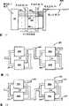
图8是说明性的本发明实施方式的颗粒分类系统的示意图表;Figure 8 is a schematic diagram of a particle sorting system of an illustrative embodiment of the present invention;
图9表示根据本发明教导的用于给平行的颗粒流分类的颗粒分类系统的一个实施方式;Figure 9 illustrates one embodiment of a particle sorting system for sorting parallel particle streams in accordance with the teachings of the present invention;
图10表示根据本发明教导的以二叉树状构形的分类组件构形成的颗粒分类系统的一个实施方式;FIG. 10 shows an embodiment of a particle classification system configured with classification components in a binary tree configuration according to the teachings of the present invention;
图11表示用来以多级方式给平行的颗粒流分类的多级颗粒分类系统的另一个实施方式;Figure 11 shows another embodiment of a multi-stage particle classification system for classifying parallel particle streams in a multi-stage manner;
图12表示根据本发明另一实施方式的并联颗粒分类系统;Figure 12 shows a parallel particle classification system according to another embodiment of the present invention;
图13表示根据本发明另一个实施方式的并联颗粒分类系统;Figure 13 shows a parallel particle classification system according to another embodiment of the present invention;
图14a和14b表示根据本发明另一个实施方式的颗粒分类系统,其包括光学掩模以允许测量颗粒尺寸和/或速度;Figures 14a and 14b show a particle sorting system according to another embodiment of the invention, which includes an optical mask to allow measurement of particle size and/or velocity;
图15表示根据本发明另一个实施方式的具有可变通道的并联分类系统;Figure 15 shows a parallel sorting system with variable channels according to another embodiment of the present invention;
图16表示根据本发明另一个实施方式的并联分类系统的可变阵列设计;Figure 16 shows a variable array design of a parallel sorting system according to another embodiment of the invention;
图17表示根据本发明另一个实施方式的并联分类系统。Figure 17 shows a parallel sorting system according to another embodiment of the present invention.
具体实施方式Detailed ways
本发明提供了一种颗粒分类系统,用来对悬浮在液体中的颗粒进行分类,颗粒分类系统基于预定特性提供了高通过量、低错误的颗粒分类。下面将相对于说明性的实施方式来描述本发明,本领域技术人员应该理解,本发明可以在大量不同的应用和实施方式中实施,在其应用方面并不特别局限于在此描述的特定实施方式。The present invention provides a particle sorting system for sorting particles suspended in a liquid, the particle sorting system providing high throughput, low error sorting of particles based on predetermined characteristics. The present invention will be described below with respect to illustrative embodiments, and those skilled in the art will appreciate that the present invention can be practiced in a multitude of different applications and embodiments and is not particularly limited in its application to the specific embodiments described herein. Way.
在此所用的术语“管道”“通道”和“流动通道”指的是形成于介质中或穿过介质的路径,该介质允许例如液体和气体的流体的移动。优选地,微流体系统中通道的横截面尺寸处于大约1.0微米到大约500微米之间的范围内,优选地在大约25微米和大约250微米之间,最优选地在大约50微米到大约150微米之间。一个本领域普通技术人员将能确定合适的流动通道容积和长度,这些范围是用来作为上限或下限包括上面列举的值,流动通道能具有任何所选的形状或布置,其例子包括线性或非线性构形和U形构形。As used herein, the terms "conduit," "channel," and "flow channel" refer to a path formed in or through a medium that permits the movement of fluids, such as liquids and gases. Preferably, the cross-sectional dimensions of the channels in the microfluidic system are in the range of between about 1.0 micron and about 500 microns, preferably between about 25 microns and about 250 microns, most preferably between about 50 microns and about 150 microns between. One of ordinary skill in the art will be able to determine suitable flow channel volumes and lengths. These ranges are intended to be used as upper or lower limits including the values listed above. The flow channels can have any chosen shape or arrangement, examples of which include linear or non-linear. Linear configuration and U-shaped configuration.
术语“颗粒”指的是分离的物质单元,包括但不局限于细胞。The term "particle" refers to an isolated unit of matter, including but not limited to cells.
在此使用的术语“传感器”指的是用来测量目标特性的装置,目标例如是颗粒。As used herein, the term "sensor" refers to a device used to measure a property of an object, such as a particle.
在此使用的术语“气泡阀”指的是产生压力脉冲以控制通过通道的流动的装置。The term "bubble valve" as used herein refers to a device that generates pressure pulses to control flow through a channel.
在此使用的术语“载流流体”指的是环绕颗粒的兼容液体护层,其用来携带一个或更多颗粒通过管道或通道。As used herein, the term "carrier fluid" refers to a sheath of compatible liquid surrounding a particle and used to carry one or more particles through a conduit or channel.
图1是根据本发明教导的颗粒分类系统10的示意图。根据本发明的一种应用,颗粒分类系统10包括用来分类颗粒的毛细管大小的封闭通道系统,通道系统包括用来引入颗粒流18的第一供给管道12和用来供应载液的第二供给管道14,第一供给管道12形成一喷嘴12a,颗粒流被引入载液的流动中。第一供给管道12和第二供给管道14与测量管道16流体连通,测量管道16用来传送悬浮在载液中的颗粒,测量管道在一个分支点21分支成第一分支通道22a和第二分支通道22b,测量区域20限定在测量管道16中并与检测器19相关联以检测穿过测量区域20的颗粒的预定特性。两个相对的气泡阀100a和100b相对于测量管道放置并且布置成与其流体连通。阀彼此相对地隔开,尽管那些普通技术人员应该懂得也能够使用其它构形。气泡阀100a和100b分别通过一对相对的侧通路24a和24b与测量管道16连通,允许液体部分地填充这些侧通路24a和24b以在其中形成弯液面25,该弯液面确定了载液与另一种流体之间的分界,所述另一种流体例如是相关联的气泡阀100的贮存器中的气体。还提供了致动器26以致动任一个气泡阀,当被致动器26致动时,气泡阀在管道中瞬间引起流动扰动以偏移其中的流动。如所示,致动器结合到气泡阀100b,第二气泡阀100a用作缓冲器以吸收由第一气泡阀100b引起的压力脉冲。FIG. 1 is a schematic diagram of a particle sorting system 10 in accordance with the teachings of the present invention. According to one application of the present invention, the particle sorting system 10 includes a capillary-sized closed channel system for sorting particles, the channel system including a
第一侧通路24b液压地连接到第一气泡阀100b中的压缩室70b,以便如果该室中的压力增加,在侧通路附近的测量管道中的流动向内移位,基本上垂直于管道中的正常流动。位置与第一侧通路24b相对的第二侧通路24a液压地连接到第二气泡阀100a中的缓冲室70a,用来吸收压力瞬变。该第一侧通路24b与第二侧通路24a共同作用以指引前面提及的通过给压缩室70b增压引起的液体移位,以便移位具有垂直于颗粒正常流过测量管道的分量。The
在给压缩室70b增压时,一些液体从第一侧通路24b瞬间排出,第二侧通路24a的弹性在增压排出时导致管道中的液体瞬间流入第二侧通路24a。两个侧通路的共同作用和它们相互连接的流体结构使得在由外部致动器26响应检测装置19发出的信号引起的液压室70b增压和降压时,通过测量管道16的流动瞬间向一旁来回移动,该瞬间液体移位具有垂直于管道中正常流动的分量,它能应用于使具有预定特性的颗粒偏移中,以将这些颗粒从混合物的其余颗粒中分离。When pressurizing the
如所示,测量管道16在分支点21分支成两个分支22a、22b,在这些分支中的流量被调节以便颗粒通常流过两个分支中的第二个22b,分支22a、22b之间的角度在0到180度之间,优选地在10到45度之间,然而,角度甚至可以是0度,该角度与两个并联的管道对应,它们之间具有笔直的分隔壁。As shown, the measuring
将被分类的颗粒优选地供给到中央流体流中的测量位置,其由无颗粒液体护层环绕。封闭颗粒流的处理是已知的,通常称为“护层流”构形,通常,通过一狭窄出口喷嘴将悬浮颗粒流喷射到在管道16中流动的无颗粒载液中来实现封闭。通过调节悬浮物和载液的流量比,能调节管道中的径向封闭以及相互的颗粒距离,相对大的载液流量导致在颗粒之间具有很大距离的更加封闭的颗粒流。The particles to be sorted are preferably fed to a measurement location in a central fluid flow, which is surrounded by a sheath of particle-free liquid. Containment of particulate flow is known, commonly referred to as a "sheath flow" configuration, and is generally achieved by injecting a stream of suspended particles through a narrow outlet nozzle into a particle-free carrier fluid flowing in
在由第一供给管道12引入的悬浮物中,能辨别两种类型的颗粒,普通颗粒18a和感兴趣颗粒18b。当在测量区域20中检测到颗粒18b中的预定特性时,检测器19发出一个信号,当检测器19响应检测到的预定特性发信号时,外部致动器26致动第一致动器气泡阀100b,在侧通路24a、24b之间的测量管道16中产生流动扰动,流动扰动使具有预定特性的颗粒18b偏移以便它沿着第一分支管道22a而不是第二分支管道22b流动。检测器与致动器26通信,以便当检测器19在颗粒中检测到预定特性时,致动器致动第一气泡阀100b以在第一气泡阀的贮存器70b中引起压力变化,第一气泡阀的致动使第一气泡阀100b中的弯液面25b偏移并在第一侧通路24b中引起瞬间压力变化。第二侧通路24a和第二气泡阀100a吸收由致动器26引起的在测量管道16中的瞬间压力变化。基本上,第二气泡阀100a的贮存器70a是具有弹性壁或容纳例如气体等可压缩流体的缓冲室,弹性性质允许液体从测量管道流入第二侧通路24a中,使得压力脉冲被吸收,并防止干扰颗粒流中未被选择的颗粒的流动。In the suspension introduced by the
在测量区域20中,用合适的传感器19对单个颗粒的特定特性进行检查,例如尺寸、形状、荧光强度以及其它对于一个普通技术人员显而易见的特性。本领域已知的适用传感器的例子是例如显微镜等各种类型的光学检测系统,机器视觉系统和用来测量颗粒电子性质的电子装置,本领域中众所周知的系统是用来测量颗粒的荧光强度的系统,这些系统包括具有用来引起荧光的合适波长的光源和用来测量被引起的荧光强度的检测系统,该方法通常与标记有荧光标识的颗粒结合使用,荧光标识即一种附属分子,其在由特定第一波长的光照射时产生另一个特定第二波长的光(荧光)。如果检测到该第二波长的光,则检测到所述特性并发出信号。In the
其它例子包括被流过测量区域的颗粒散射的光的测量,关于颗粒的尺寸和形状来解释散射的生成信息,在检测到预定特性时,能采用该信息以发出信号。Other examples include the measurement of light scattered by particles flowing through the measurement region, interpreting the scatter to generate information about the size and shape of the particles which can be used to signal when a predetermined characteristic is detected.
用来给第一气泡阀的压缩室加压的致动器26可以包括外部致动器,其响应来自传感器的表示颗粒具有选定的预定特性的信号。有两类适合增加压力的外部致动器,第一类直接将气压提供给第一侧通路24b中的液体,例如,致动器可以包括用开关阀连接到侧通路24b中的液体容积的高压气体源,开关的致动将通路连接到高压气体源,这使液体中的弯液面偏移。在没有致动时,开关将通路24b连回到正常的工作压力。The
按照另一方案,位移致动器可以与具有可移动壁的封闭压缩室结合使用。当位移致动器使压缩室的壁向内移位时,内部压力增加,如果可移动壁移回到原始位置,压力就减回到正常工作压力。合适的位移致动器的一个例子是电磁致动器,其在线圈通电时引起柱塞的移位。另一个例子是压电材料的使用,例如呈圆柱体或一堆盘状物的形式,其在施加电压时产生线性移位。两种类型的致动器都接合压缩室70的可移动壁以引起其中的压力变化。According to another aspect, a displacement actuator may be used in combination with a closed compression chamber having movable walls. When the displacement actuator displaces the walls of the compression chamber inwardly, the internal pressure increases, and if the movable wall moves back to its original position, the pressure decreases back to normal working pressure. One example of a suitable displacement actuator is an electromagnetic actuator which causes displacement of the plunger when the coil is energized. Another example is the use of piezoelectric material, for example in the form of a cylinder or a stack of disks, which produces a linear displacement when a voltage is applied. Both types of actuators engage the movable walls of the
图2至4表示图1的颗粒分类系统10中的开关40的开关操作。在图2中,检测器19感知颗粒中的预定特性并产生信号以致动致动器26。在致动器致动时,第一气泡阀100b的贮存器70b内的压力增加,使弯液面25b偏移并导致液体从第一侧通路24b瞬间排出,如箭头所示。因为第二气泡阀100a的贮存器的弹性性质,所以管道中在该点发生的突然压力增加使得液体流入第二侧通路24a,液体向第二侧通路24a中的这个移动用一箭头表示。结果,如能在图中看到的,通过测量管道16的流动被偏移,使得位于第一侧通路24b和第二侧通路24a之间的所选的感兴趣颗粒18b垂直于其正常状态下的流动方向移动,对测量管道16的流动阻力、第一分支22a和第二分支22b被选定以便来往于第一侧通路24b和第二侧通路24a的优选流动方向具有明显的分量,该分量垂直于通过测量管道16的正常流动。例如,通过使第一分支22a和第二分支22b的流动阻力大于第一侧通路24b和第二侧通路24a的流动阻力来达到该目标。2 to 4 illustrate the switching operation of the
图3表示当感兴趣颗粒18b离开第一侧通路24b和第二侧通路24a之间的容积时,在第一气泡阀贮存器减压期间的颗粒分类系统10。致动器26退出工作,使得贮存器70a、70b内部的压力返回到正常压力,在该减压阶段,在气泡阀的两个贮存器70a、70b之间有负压差,使得液体与前面图中所示的液流相反地流过第一侧通路24b和第二侧通路24a,如箭头所示。FIG. 3 shows the particle classification system 10 during depressurization of the first bubble valve reservoir when the particles of
图4表示在完成开关程序之后的颗粒分类系统10。气泡阀贮存器内的压力相等,使得通过测量管道16的流动正常,当感兴趣颗粒18b已经径向移位时,它将流入第一分支22a,同时其它颗粒继续流入第二分支22b,从而基于预定特性分开颗粒。Figure 4 shows the particle sorting system 10 after completion of the switching procedure. The pressure in the bubble valve reservoir is equalized so that the flow through the measuring
为了以高速对颗粒进行分类,颗粒的检测和有选择偏移的这个处理每秒可以重复许多次。采用所述的流体开关,能以高达每秒大约几百次开关操作的速度执行开关操作,产生大约每小时上百万分类颗粒的分类速度。This process of detection and selective deflection of particles can be repeated many times per second in order to sort particles at high speed. With the described fluid switch, switching operations can be performed at a rate of up to about several hundred switching operations per second, resulting in a sorting rate of about millions of sorted particles per hour.
根据本发明另一个实施方式,致动器气泡阀100b和缓冲器气泡阀100a可以放置在不同位置中,例如,如图5中所示,致动器气泡阀100b与第一侧通路24b和/或缓冲器气泡阀100a与第二侧通路24a可以从分支点21向上游放置,元件可以放置在任何合适的位置中,以便致动器室70b和缓冲器室70a之间的流动阻力小于这些后面的元件中的任一个和其它压力源之间的流动阻力。更具体地,致动器室70b和缓冲器室70a可以这样放置,即它们之间的流动阻力小于选定的颗粒和颗粒流中随后的颗粒之间的流动阻力。从而,照这样的元件定位防止了由上述偏移单个选定颗粒的方法产生的压力波向上游或向下游传播,影响颗粒流中其余颗粒的流动。如果在流动阻力上的差别较大,则具有关联的压力瞬变的流体开关操作与系统其余部分中的流动特性隔离的程度就较高。而且,为了分类而施加的生成压力脉冲的原位阻尼允许包括多个开关40的分类网络的实施,每个开关都与其它开关液压地和气压地隔离。According to another embodiment of the present invention, the
根据图6中所示的另一个实施方式,本发明的颗粒分类系统可以结合一个或更多用作缓冲器的气泡阀,例如阀100b,使用任何合适的压力波发生器(代替气泡阀)。例如,压力波发生器260可以包括一个致动器,例如压电柱或步进电机,其设置有能直接地或通过通道系统的偏移作用于流动液体上的柱塞,以当致动器被一信号致动时选择地偏移颗粒。其它合适的压力波发生器包括电磁致动器、热力气动致动器和通过施加热脉冲在流动液体中产生汽泡的热脉冲发生器。缓冲器气泡阀100b放置成吸收由压力波发生器260产生的压力波,以防止颗粒流其它颗粒中的流动扰动。缓冲器100b的弹簧常数可以根据特定需要,通过改变缓冲器室70b的容积、侧通路24b的横截面积和/或形成缓冲器室70b的挠性膜片(图7中附图标记72)的刚性或厚度来进行改变。According to another embodiment shown in FIG. 6, the particle classification system of the present invention may incorporate one or more bubble valves acting as buffers, such as
图7表示根据本发明教导的阀100的一实施方式,其适合产生压力脉冲以将感兴趣的颗粒与颗粒流中的其它颗粒分开和/或充当吸收压力脉冲的缓冲器。如所示,阀100靠近侧通路24a或24b地形成,侧通路24a或24b形成于通向测量管道16的基片中。侧通路24a包括由一缝隙在通路的侧壁中形成的流体接口17,密封的压缩室70邻接侧通路24a定位并通过流体接口与侧通路连通。说明性的室70由密封件71和挠性膜片72形成,侧通路24a中的载流流体在侧通路和压缩室之间的接口处形成弯液面25,致动器26压下挠性膜片以增加压缩室中的压力,这使弯液面偏移并在载流流体中引起压力脉冲。FIG. 7 illustrates one embodiment of a valve 100 adapted to generate pressure pulses to separate particles of interest from other particles in a particle stream and/or to act as a buffer to absorb pressure pulses in accordance with the teachings of the present invention. As shown, the valve 100 is formed adjacent to the
图8表示具有合适的供给管道52以及第一出口管道54和第二出口管道56的分类组件50,供给管道52用来提供被分类的颗粒流,第一出口管道54和第二出口管道56中的任一个都能携带在分类组件50中分类的颗粒。分类组件50包括检测器系统19,其用来检测通过供给管道52进入分类组件50的颗粒,检测器系统能操作地连接到用来提供所需的开关能力以分类颗粒的开关40。图1的第一分支22b和第二分支22a能布置成与出口管道54和第二出口管道56流体地连接。Figure 8 shows a
图9表示根据本发明另一实施方式的颗粒分类系统500,其包括多个能以任何合适的构形结合在一起的分类组件50,例如,该实施方式中的组件50并联地结合。分类组件50的出口管道54结合到第一联合出口58,第二出口管道56结合到第二联合出口60。分类组件的并联布置产生联合的分类组件50的系统,其总分类速度是单个分类组件50的分类速度的N倍,其中N是并联连接的分类组件50的数量。Figure 9 shows a
图10表示根据另一个实施方式的颗粒分类系统550,其包括与第二分类组件50b串联的第一分类组件50a,第二分类组件50b可以被装备用来对这样一些颗粒进行分类,这些颗粒的预定特性与由第一分类组件50a分类的颗粒的预定特性相同或不同。颗粒流通过供给管道52进入第一分类组件50a,并可以包含至少两种类型的颗粒,第一种类型的颗粒在第一分类组件50a中分类并通过第一出口管道54a离开,剩下的颗粒通过第二出口管道56a离开第一分类组件50a,并通过第二供给管道52b引入第二分类组件50b。从该颗粒流,具有另一种预定特性的颗粒被分类并通过第二出口管道54b离开,两种预定特性都不具有的颗粒通过第二出口管道56b离开第二分类组件50b。那些普通技术人员应该容易懂得,能使用任何合适类型的分类组件50,并且取决于所希望的结果,能将它们以各种方式结合在一起。Figure 10 shows a
图11表示根据本发明另一个实施方式的高通过量低错误分类的分层体系结构。说明性的实施方式是两级颗粒分类系统800,其用来给第一级中的多个平行颗粒流分类,集合第一级的输出,然后对第一级的输出进行二次分类处理。悬浮液80中来自颗粒输入腔室88的颗粒输入流被拆分到N个单独的分类通道81a-81n中,每个通道每秒都能对选定数量的颗粒进行分类。每个通道81都包括检测区域84和开关区域82,检测区域84用来检查颗粒并识别具有预定特性的颗粒,开关区域82用来将具有预定特性的颗粒与颗粒流中的其它颗粒分开,如上所述。开关区域82基于在检测区域84中测定的颗粒特性,在其开关区域82中产生两个颗粒输出流:“选定”流和“拒绝”流。来自每个通道的“选定”流在集合区域86中集合成一个将在第二分类通道810中再次分类的流,如所示,第二分类通道810基于预定特性重复检测和分类的分类处理。Figure 11 shows a hierarchical architecture for high-throughput low-error classification according to another embodiment of the present invention. The illustrative embodiment is a two-stage
假设每个单独通道分类处理都产生一些错误选择的出错(y)率(y是被错误“选择”的颗粒小于一的概率),则对于所画的2级分层结构而言,分层体系结构产生较低的出错率y2,或对于n级分层结构出错率为yn。例如,如果单个通道出错率是1%,则2级的出错率是0.01%或104分之一。Assuming that each individual channel sorting process yields some misselection error (y) rate (y is the probability of being incorrectly "selected" by a particle less than one), then for the drawn 2-level hierarchy, the hierarchy The structure yields a lower error rate y2 , or yn for an n-level hierarchical structure. For example, if the error rate for a single channel is 1%, the error rate for
按照另一方案,分层结构中每个第二通道能具有M个第一组,每个第一组具有N个分类通道。假设应用想捕获以比率z存在于输入中的颗粒,而单个通道分类器具有的最大分类率为每秒x个颗粒,则系统通过量是每秒M*N*x个颗粒,每秒在N个通道中集合的颗粒数量是N*x*z,因此N*z必须小于1以便从N个通道集合的所有颗粒能由单独的第二通道分类。为了增加通过量超过N=1/z,必须增加若干N个第一通道+1个第二通道的并联的组,,然后,总通过量是具有M个第二通道的M*N*x的结果。According to another solution, each second channel in the hierarchy can have M first groups, and each first group has N sorting channels. Suppose the application wants to capture particles present in the input at rate z, and a single channel classifier has a maximum classification rate of x particles per second, then the system throughput is M*N*x particles per second, at N The number of particles aggregated in channels is N*x*z, so N*z must be less than 1 so that all particles aggregated from N channels can be sorted by a single second channel. In order to increase the throughput beyond N=1/z, it is necessary to add a number of parallel groups of N first channels + 1 second channels, and then the total throughput is M*N*x with M second channels result.
图12表示根据本发明另一个实施方式的并联-串联颗粒分类系统160。并联-串联颗粒分类系统160包括第一并联分类组件161和第二并联分类组件162,第一分类组件161适用于多重标记的颗粒中,具有两个标记的颗粒被挑选出并通过出口通道165传送。Figure 12 shows a parallel-series
图13表示另一个并联-串联颗粒分类系统170。第一并联分类组件171将具有第一标记的颗粒分离,从不同通道中收集颗粒并通过第一出口通道175传送具有第一标记的颗粒。然后,将所有其它颗粒送入第二并联分类器172,其用来给具有第二标记的颗粒分类。具有第二标记的颗粒被收集并通过第二出口通道176传送,既不具有第一标记也不具有第二标记的颗粒通过第三出口通道177传送。FIG. 13 shows another parallel-series
根据图14a和14b中所示的本发明的一个实施方式,颗粒分类系统可以包括用来测量颗粒速度、位置和/或尺寸的传感器,速度、位置和/或尺寸的测量可以与用来分类的颗粒分选同时进行或不同时进行。在基于图11中所示系统的并联通道中,不同的通道可以具有不同的流动阻力,使得每个通道中的颗粒或细胞的速度不同。在检测区域84与开关区域82分隔距离L的系统中,为了设定开关延时T(即,相对于检测到目标颗粒的瞬间延迟开关致动的时间),必须知道通道81中的颗粒速度。According to one embodiment of the invention shown in Figures 14a and 14b, the particle sorting system may include sensors for measuring particle velocity, position and/or size, which may be compared to the sensors used for sorting. Particle sorting is performed simultaneously or not. In parallel channels based on the system shown in Figure 11, different channels can have different flow resistances, so that the velocity of particles or cells in each channel is different. In systems where the
在大多数检测细胞或颗粒的光学系统中,细胞在检测区域中的光电检测器上引起光的区域具有比细胞直径尺寸大得多的尺寸,因而,当在检测区域中检测到光时,细胞可能在区域中的任何地方,使得难以正确定出细胞的精确位置。为了提供更精确的检测,可以使光检测器的许多象素塞满检测区域,但这具有很大的成本并需要复杂的配套电子设备。In most optical systems for detecting cells or particles, the area where the cell induces light on the photodetector in the detection area has a size much larger than the diameter of the cell, so that when light is detected in the detection area, the cell could be anywhere in the region, making it difficult to correctly pinpoint the exact location of the cell. To provide more accurate detection, it is possible to cram many pixels of the photodetector into the detection area, but this is costly and requires complex supporting electronics.
根据本发明说明性的实施方式,可以将光学掩模140加到检测区域以通过直接在分类芯片上堆积一个“遮蔽图案”来提供精确的速度检测。遮蔽图案可以如此堆积,即使得遮蔽图案的边缘相对于细胞分类致动器区域82精确定位(用当前技术达到<1微米的精度)。当细胞没有被遮蔽时,在检测区域84中从细胞上捕获光的单独的光检测器将看到光,被已知长度掩模的相连不透明部件“条状物”之一断开的光持续时间允许速度测量。According to an illustrative embodiment of the invention, an optical mask 140 may be added to the detection area to provide accurate velocity detection by depositing a "masking pattern" directly on the sorting chip. The masking patterns can be stacked such that the edges of the masking patterns are precisely positioned relative to the cell sorting actuator area 82 (with current technology to an accuracy of <1 micron). When the cells are not obscured, the light will be seen by the individual photodetectors that capture the light from the cells in the
掩模图案具有几个尺寸范围在1微米等级中从10微米到30微米的条状物141,该掩模图案导致仅仅尺寸大于细胞的条状物才将来自细胞的信号减到最小,因而,这种图案还能用来与细胞信号无关地测量细胞尺寸。这种“梯度掩模”还在光检测器中产生一个图案,能对其进行分析以对速度进行几次测量,减小速度估算的差异。由掩模140引起的光中的图案还允许检测器识别掩模140中的每个边,如果条状物141都是相同的,则每个条状物的光信号将是相同的,一个人仅仅能通过顺序来区分它们,因而,梯度掩模图案允许单独的检测器查看广阔的区域(几倍于细胞尺寸)以测量细胞速度,相对于通道结构以大约1微米的精度测量在检测区域84内的精确位置和芯片上的致动器位置,以梯度图案给出的精度识别细胞尺寸。梯度掩模140允许检测器与光学系统的放大率或光检测器本身的性质无关地测量这些参数。The mask pattern has
根据本发明的教导,本领域技术人员应该懂得在分类系统中用于测量颗粒尺寸、位置和/或速度的其它设备,对于那些本领域普通技术人员来说,很容易利用和知道合适的设备。Other devices for measuring particle size, position and/or velocity in a classification system will be appreciated by those skilled in the art in light of the teachings of the present invention, and suitable devices are readily available and known to those of ordinary skill in the art.
根据图15中所示的另一个实施方式,颗粒分类系统包括不同分类通道的阵列8000。就空间、光能的使用和最佳外部致动器的匹配而言,包括一系列不同分类通道810a-810n的并联阵列的使用是更有效的。由于能用如上所述的传感器精确地检测颗粒速度,所以通道不需要在性质检测和开关致动之间的固定时延来偏移具有检得性质的颗粒,因而,通道的某些参数,例如检测器84和开关82之间的距离L或检测器84和开关82之间的路径形状能改变。According to another embodiment shown in Fig. 15, the particle sorting system comprises an
用单个激光进行方向垂直于芯片的每个波长的光照射,需要激光照射一个面积,该面积如下确定:(通道数量)×((检测区域的通道宽度)+(通道间的间隔C))(见图15)。然而,能吸收光线以产生荧光的有效面积仅仅是通道的面积:(通道数量)×(通道宽度),这留下一个填充系数:(通道宽度)/(通道宽度+C),填充系数优选地接近100%以避免浪费可用的输入光。Irradiation of each wavelength of light with a direction perpendicular to the chip with a single laser requires the laser to irradiate an area, which is determined as follows: (number of channels) × ((channel width of the detection area) + (interval C between channels))( See Figure 15). However, the effective area that can absorb light to produce fluorescence is only the area of the channel: (number of channels) x (channel width), which leaves a fill factor: (channel width)/(channel width+C), the fill factor is preferably Closer to 100% to avoid wasting available input light.
因而,在并联分类系统中将通道间的间隔减到最小对于光检测区域和光学系统效率是重要的。在图16中所示的本发明的可变阵列设计中,检测区域84中的通道间隔接近通道的宽度,以便光的利用大约接近50%。作用区域82中的通道间隔可以更大,如图16中所示。致动器26沿着通道的位置也可以改变,以产生外部驱动装置致动器的更大可用半径。Thus, minimizing the spacing between channels in a parallel sorting system is important for light detection area and optical system efficiency. In the variable array design of the present invention shown in FIG. 16, the channel spacing in the
可变阵列8000还可以在所选的通道中包括弯曲处,用来平衡所有通道的流动阻力,以便如果给出一个跨越所有通道的恒定压力降,则颗粒速度几乎是匹配的。弯曲处能加到所示系统的上游或下游,即,在检测器和致动器之间的区域上。由于从设计中知道每个通道的检测区域82I和其致动器26i之间的长度Li,所以与关于保留哪些颗粒的确定同时进行的颗粒速度测量提供了一种改进的细胞分类系统。The
图17表示根据本发明又一个实施方式的颗粒分类系统1700,颗粒分类系统1700包括多个平行工作的分类组件1701。系统1700包括用于将样品引入到每个分类组件中的输入区域1710和检测区域1720,检测区域1720用来测量检测区域的每个分类通道1702中颗粒的预定特性。系统还包括开关区域1730,其在每个分类组件中包括一致动器,用来将具有预定特性的颗粒与不具有预定特性的颗粒分离。如所示,在图17的实施方式中,检测区域1720中的分类通道1702之间的距离小于开关区域1730中的通道间的距离,当用激光来检测颗粒时,检测区域中的紧密间隔能节省成本,同时开关区域1730中更远的间距适应各种尺寸的致动器。Fig. 17 shows a
颗粒分类系统1700还可以包括第二分类组件1740,其基于一预定特性重复检测和分类的分类处理以增加分类处理的精度。根据一个实施方式,系统可以在第一分类组件1701的阵列和第二分类组件1740之间包括浓缩区域1750,用来将颗粒从第一分类处理过渡到第二分类处理。根据一个说明性的实施方式,在将颗粒传送到第二分类组件1740之前,浓缩区域1750通过从颗粒中除去过剩的载流流体来过渡颗粒。浓缩区域1750还可以包括水合装置,用来在浓缩之后将第二薄层流体加到颗粒上。浓缩区域1750可以包括插入出口通道1703中的膜片、与出口通道1703的浓缩通道相交和将出口通道与浓缩通道分开的膜片,在将所选的颗粒传送到第二分类组件1740中之前,过剩的载流流体在出口通道1703中通过膜片从所选颗粒流中除去并进入浓缩通道。The
在与本申请同一日期申请的代理人案卷号No.TGZ-023中描述了用来形成浓缩区域的合适系统,其内容在此并入作为参考。A suitable system for forming concentrated regions is described in Attorney Docket No. TGZ-023, filed on the same date as this application, the contents of which are incorporated herein by reference.
根据说明性的实施方式,被除去的载流流体可以再循环并送回到第一通道的入口中,再循环通道或其它设备可以将浓缩区域连接到第一通道,以允许载流流体重新用于随后的分类处理。按照另一方案,载流流体可以从被拒绝的颗粒中除去,并在丢弃被拒绝的颗粒之前引入第一通道入口中。According to an illustrative embodiment, the removed carrier fluid may be recycled and sent back into the inlet of the first channel, and a recirculation channel or other device may connect the enrichment region to the first channel to allow the carrier fluid to be reused. for subsequent classification. According to another aspect, the carrier fluid may be removed from the rejected particles and introduced into the first channel inlet before the rejected particles are discarded.
已经关于说明性的实施方式对本发明进行了描述,由于在不背离本发明范围的情况下,在上述构造中可以作出某些改变,所以应该认为包含在上述说明书中或在附图中所示的全部内容是说明性的而并非限制性的。Having described the invention with respect to illustrative embodiments, since certain changes may be made in the above construction without departing from the scope of the invention, it should be considered that what is included in the foregoing description or shown in the accompanying drawings The entire contents are illustrative and not restrictive.
还应该了解,下面的权利要求覆盖了在此描述的发明的全部一般的和特定的特征以及发明范围的所有陈述,根据语言,可以说发明落入它们之间。It should also be understood that the following claims cover all generic and specific features of the invention described herein and all statements of scope of the invention according to the language that the invention may be said to fall therebetween.
已经描述了本发明,作为新的所要求的和被专利证书保护的是。Having described the invention, what is claimed as new and protected by Letters Patent is.
Claims (36)
Applications Claiming Priority (11)
| Application Number | Priority Date | Filing Date | Title |
|---|---|---|---|
| US37325602P | 2002-04-17 | 2002-04-17 | |
| US60/373,256 | 2002-04-17 | ||
| US10/179,586US6877528B2 (en) | 2002-04-17 | 2002-06-24 | Microfluidic system including a bubble valve for regulating fluid flow through a microchannel |
| US10/179,488 | 2002-06-24 | ||
| US10/179,488US6808075B2 (en) | 2002-04-17 | 2002-06-24 | Method and apparatus for sorting particles |
| US10/179,586 | 2002-06-24 | ||
| US41105802P | 2002-09-16 | 2002-09-16 | |
| US60/411,058 | 2002-09-16 | ||
| US10/329,008 | 2002-12-23 | ||
| US10/329,008US6976590B2 (en) | 2002-06-24 | 2002-12-23 | Method and apparatus for sorting particles |
| PCT/US2003/012368WO2003089158A1 (en) | 2002-04-17 | 2003-04-17 | Method and apparatus for sorting particles |
Related Child Applications (1)
| Application Number | Title | Priority Date | Filing Date |
|---|---|---|---|
| CN200910168699ADivisionCN101693239A (en) | 2002-04-17 | 2003-04-17 | Method and apparatus for sorting particles |
Publications (2)
| Publication Number | Publication Date |
|---|---|
| CN1662311A CN1662311A (en) | 2005-08-31 |
| CN1662311Btrue CN1662311B (en) | 2010-11-03 |
Family
ID=29255667
Family Applications (1)
| Application Number | Title | Priority Date | Filing Date |
|---|---|---|---|
| CN03814212.0AExpired - LifetimeCN1662311B (en) | 2002-04-17 | 2003-04-17 | Method and apparatus for sorting particles |
Country Status (9)
| Country | Link |
|---|---|
| EP (1) | EP1499453B1 (en) |
| JP (2) | JP4153434B2 (en) |
| KR (1) | KR100975438B1 (en) |
| CN (1) | CN1662311B (en) |
| AU (1) | AU2003228630B2 (en) |
| BR (1) | BR0309321A (en) |
| CA (1) | CA2482869C (en) |
| IL (1) | IL164601A (en) |
| WO (1) | WO2003089158A1 (en) |
Families Citing this family (64)
| Publication number | Priority date | Publication date | Assignee | Title |
|---|---|---|---|---|
| GB9926335D0 (en)* | 1999-11-05 | 2000-01-12 | Powderject Res Ltd | Apparatus and method for dispensing small quantities of particles |
| US9943847B2 (en) | 2002-04-17 | 2018-04-17 | Cytonome/St, Llc | Microfluidic system including a bubble valve for regulating fluid flow through a microchannel |
| US6808075B2 (en) | 2002-04-17 | 2004-10-26 | Cytonome, Inc. | Method and apparatus for sorting particles |
| US6976590B2 (en) | 2002-06-24 | 2005-12-20 | Cytonome, Inc. | Method and apparatus for sorting particles |
| BRPI0518824B1 (en)* | 2004-12-03 | 2017-11-28 | Cytonome/St, Llc | "PARTICLE CARTRIDGE FOR PARTICLE PROCESSING AND METHOD OF PROCESSING OF A SAMPLE" |
| US9260693B2 (en) | 2004-12-03 | 2016-02-16 | Cytonome/St, Llc | Actuation of parallel microfluidic arrays |
| US8273294B2 (en)* | 2005-07-01 | 2012-09-25 | Honeywell International Inc. | Molded cartridge with 3-D hydrodynamic focusing |
| JP4745755B2 (en)* | 2005-08-23 | 2011-08-10 | セイコーインスツル株式会社 | Fractionation microchip and fractionation device |
| EP1767273A1 (en)* | 2005-09-27 | 2007-03-28 | Genimin | Method and device for the concentration of solid particles |
| KR100787234B1 (en)* | 2006-02-17 | 2007-12-21 | 한국기계연구원 | Particle Separation Device and Particle Separation Method |
| CN100551550C (en)* | 2006-09-25 | 2009-10-21 | 瑞鼎科技股份有限公司 | fluid particle separating device |
| CA2580589C (en)* | 2006-12-19 | 2016-08-09 | Fio Corporation | Microfluidic detection system |
| US8691164B2 (en)* | 2007-04-20 | 2014-04-08 | Celula, Inc. | Cell sorting system and methods |
| KR100945463B1 (en)* | 2008-02-04 | 2010-03-05 | 광주과학기술원 | Microfluidic chamber, device and method for measuring microparticle image velocity |
| FR2931085B1 (en)* | 2008-05-13 | 2011-05-27 | Commissariat Energie Atomique | METHOD OF SORTING PARTICLES OR AMAS FROM PARTICLES IN A FLUID CIRCULATING IN A CHANNEL |
| TWI458980B (en)* | 2008-07-16 | 2014-11-01 | Raydium Semiconductor Corp | Connecting device and testing system |
| WO2011086990A1 (en)* | 2010-01-15 | 2011-07-21 | 株式会社オンチップ・バイオテクノロジーズ | Disposable chip flow cell and cell sorter using same |
| CN101786675A (en)* | 2010-03-09 | 2010-07-28 | 清华大学 | Device and method for separating multi-parameter wastewater sources |
| JP5845533B2 (en)* | 2010-10-12 | 2016-01-20 | 株式会社オンチップ・バイオテクノロジーズ | A method of purifying and concentrating specific cells from many types of cells using fluorescent dyes that are selectively taken up into specific cells |
| JP2012095550A (en)* | 2010-10-29 | 2012-05-24 | Sony Corp | Cell sorting apparatus, cell sorting chip, and cell sorting method |
| JP5659698B2 (en)* | 2010-10-29 | 2015-01-28 | ソニー株式会社 | Sample inflow device, sample inflow tip, and sample inflow method |
| JP5720233B2 (en)* | 2010-12-17 | 2015-05-20 | ソニー株式会社 | Microchip and fine particle sorting device |
| KR101270424B1 (en) | 2011-02-17 | 2013-06-07 | 부산대학교 산학협력단 | Separating device of micro particles and separation method of it |
| CN104870077A (en) | 2012-01-31 | 2015-08-26 | 宾夕法尼亚州立大学研究基金会 | Microfluidic manipulation and particle sorting using tunable surface standing acoustic waves |
| KR101420917B1 (en)* | 2012-05-22 | 2014-08-14 | 한양대학교 산학협력단 | Device for cell counting and method for manufacturing the same |
| US20130319861A1 (en)* | 2012-05-30 | 2013-12-05 | Berkeley Lights, Inc. | Outputting A Droplet Of Liquid Medium From A Device For Processing Micro-Objects In The Medium |
| JP6172147B2 (en)* | 2012-07-18 | 2017-08-02 | ソニー株式会社 | Fine particle sorting device and fine particle sorting method |
| JP6036496B2 (en)* | 2012-07-24 | 2016-11-30 | ソニー株式会社 | Fine particle sorting method |
| EP2879778B1 (en) | 2012-08-01 | 2020-09-02 | The Penn State Research Foundation | High efficiency separation and sorting of particles and cells |
| JP5910412B2 (en)* | 2012-08-16 | 2016-04-27 | ソニー株式会社 | Microparticle sorting method and microchip for sorting microparticles |
| CN105008895B (en) | 2012-10-15 | 2019-02-15 | 纳诺赛莱克特生物医药股份有限公司 | System, apparatus and method for particle sorting |
| JP2013081943A (en)* | 2012-11-02 | 2013-05-09 | Kurabo Ind Ltd | Apparatus for sorting fine particle in fluid |
| WO2014085627A1 (en) | 2012-11-27 | 2014-06-05 | The Penn State Research Foundation | Spatiotemporal control of chemical microenvironment using oscillating microstructures |
| WO2015009284A1 (en)* | 2013-07-16 | 2015-01-22 | Premium Genetics (Uk) Ltd. | Microfluidic chip |
| US8820538B1 (en)* | 2014-03-17 | 2014-09-02 | Namocell LLC | Method and apparatus for particle sorting |
| US10564088B2 (en) | 2014-10-09 | 2020-02-18 | Kinetic River Corp. | Particle analysis and sorting apparatus and methods |
| US9658148B2 (en)* | 2014-10-09 | 2017-05-23 | Kinetic River Corp. | Particle analysis and sorting apparatus and methods |
| US11965812B2 (en) | 2014-10-09 | 2024-04-23 | Kinetic River Corp. | Apparatus and methods for particle analysis and autofluorescence discrimination |
| US11740174B2 (en) | 2014-10-09 | 2023-08-29 | Kinetic River Corp. | Apparatus and methods for particle analysis and autofluorescence discrimination |
| JP6962563B2 (en)* | 2015-05-12 | 2021-11-05 | 株式会社オンチップ・バイオテクノロジーズ | Single particle analysis method and system for its analysis |
| JP6713730B2 (en)* | 2015-05-20 | 2020-06-24 | シスメックス株式会社 | Cell detection device and cell detection method |
| CN104976976B (en)* | 2015-07-09 | 2018-03-13 | 苏州工业园区迈泰克自动化技术有限公司 | A kind of valve full size detecting machine |
| KR101782721B1 (en)* | 2015-10-23 | 2017-10-23 | 부산대학교 산학협력단 | A t-type particle classifier and a method for classifying particles by using the classifier |
| WO2017069579A1 (en)* | 2015-10-23 | 2017-04-27 | 부산대학교 산학협력단 | T-shaped channel apparatus for separating particles and separating method using same |
| JP6450337B2 (en) | 2016-03-17 | 2019-01-09 | 国立大学法人名古屋大学 | Cell sorting device and cell sorting method |
| CN105973780A (en)* | 2016-05-12 | 2016-09-28 | 绍兴文理学院 | Abraded micro-particle online monitoring method adopting temperature control, adsorption and adjacent capacitor |
| US11254557B2 (en)* | 2016-05-17 | 2022-02-22 | Sony Corporation | Particle extraction apparatus and particle extraction method |
| US10094776B2 (en)* | 2016-07-18 | 2018-10-09 | Honeywell International Inc. | Dust sensor with mass separation fluid channels and fan control |
| DE102016224446A1 (en)* | 2016-12-08 | 2018-06-14 | Siemens Aktiengesellschaft | Housing structure with a cavity and a sample chamber connected thereto and method for their preparation |
| US20190374956A1 (en)* | 2017-01-09 | 2019-12-12 | Sabic Global Technologies B.V. | Particle separator and particle separation method |
| DE102017201252A1 (en) | 2017-01-26 | 2018-07-26 | Universität Ulm | Method and device for the examination of cells |
| US11579073B2 (en)* | 2017-02-07 | 2023-02-14 | Nodexus Inc. | Microfluidic system with combined electrical and optical detection for high accuracy particle sorting and methods thereof |
| CN110475849B (en)* | 2017-03-31 | 2023-03-28 | 麻省理工学院 | Systems, articles, and methods for flowing particles |
| GB2561587B (en)* | 2017-04-19 | 2021-05-19 | The Technology Partnership Plc | Apparatus and method for sorting microfluidic particles |
| KR101934009B1 (en) | 2017-05-25 | 2018-12-31 | 충남대학교산학협력단 | Microfluidic Separation System Based on Image |
| CN107297334B (en)* | 2017-05-31 | 2020-04-17 | 清华大学 | Cell sorting device and method based on micro-spark cavitation |
| US11754486B2 (en) | 2017-06-19 | 2023-09-12 | Massachusetts Institute Of Technology | Systems and methods for measuring properties of particles |
| GB2566002B (en)* | 2017-06-22 | 2019-10-23 | Sphere Fluidics Ltd | Droplet dispensing systems |
| CN109709003B (en)* | 2017-10-25 | 2021-07-30 | 中国航发商用航空发动机有限责任公司 | Impurity particle detection sensor testing device and method |
| CN111630364A (en)* | 2018-01-29 | 2020-09-04 | 惠普发展公司,有限责任合伙企业 | Particle classification |
| WO2019167510A1 (en)* | 2018-03-02 | 2019-09-06 | ソニー株式会社 | Method for optimizing fine particle suction condition, fine particle separation device, fine particle separation system, and fine particle separation program |
| JP7545729B2 (en)* | 2020-01-22 | 2024-09-05 | シンクサイト株式会社 | Cell sorters and flow cells |
| JP7042301B2 (en)* | 2020-06-04 | 2022-03-25 | シスメックス株式会社 | Cell detection method |
| AU2021393736A1 (en)* | 2020-12-01 | 2023-06-22 | Samplix Aps | System and method for sorting of particles |
Citations (8)
| Publication number | Priority date | Publication date | Assignee | Title |
|---|---|---|---|---|
| US3508654A (en)* | 1966-08-31 | 1970-04-28 | Ibm | Particle separation apparatus |
| US3984307A (en)* | 1973-03-05 | 1976-10-05 | Bio/Physics Systems, Inc. | Combined particle sorter and segregation indicator |
| US4175662A (en)* | 1977-04-12 | 1979-11-27 | Tibor Zold | Method and device for sorting particles suspended in an electrolyte |
| CN87101633A (en)* | 1986-02-26 | 1987-10-21 | 通用信号公司 | Separation systems for separating liquids from slurries consisting of liquids and particulate matter |
| US4756427A (en)* | 1984-09-11 | 1988-07-12 | Partec Ag | Method and apparatus for sorting particles |
| CN1130104A (en)* | 1994-12-28 | 1996-09-04 | 株式会社佐竹制作所 | Particle color sorting device |
| US5837200A (en)* | 1995-06-02 | 1998-11-17 | Bayer Aktiengesellschaft | Sorting device for biological cells or viruses |
| US5976336A (en)* | 1997-04-25 | 1999-11-02 | Caliper Technologies Corp. | Microfluidic devices incorporating improved channel geometries |
Family Cites Families (12)
| Publication number | Priority date | Publication date | Assignee | Title |
|---|---|---|---|---|
| US3560754A (en)* | 1965-11-17 | 1971-02-02 | Ibm | Photoelectric particle separator using time delay |
| US3827555A (en)* | 1973-03-05 | 1974-08-06 | Bio Physics Systems Inc | Particle sorter with segregation indicator |
| JPH01170853A (en)* | 1987-12-25 | 1989-07-05 | Hitachi Ltd | Cell screening device |
| US5101978A (en)* | 1989-11-27 | 1992-04-07 | The United States Of America As Represented By The Secretary Of The Army | Fluidic sorting device for two or more materials suspended in a fluid |
| GB9008044D0 (en)* | 1990-04-09 | 1990-06-06 | Hatfield Polytechnic Higher Ed | Microfabricated device for biological cell sorting |
| AU6541596A (en)* | 1995-06-16 | 1997-01-15 | University Of Washington | Microfabricated differential extraction device and method |
| US5885470A (en)* | 1997-04-14 | 1999-03-23 | Caliper Technologies Corporation | Controlled fluid transport in microfabricated polymeric substrates |
| JP2002503334A (en)* | 1996-09-04 | 2002-01-29 | テクニカル ユニバーシティ オブ デンマーク | Microflow system for particle separation and analysis |
| US6221654B1 (en)* | 1996-09-25 | 2001-04-24 | California Institute Of Technology | Method and apparatus for analysis and sorting of polynucleotides based on size |
| WO2000070080A1 (en)* | 1999-05-17 | 2000-11-23 | Caliper Technologies Corp. | Focusing of microparticles in microfluidic systems |
| US6597438B1 (en)* | 2000-08-02 | 2003-07-22 | Honeywell International Inc. | Portable flow cytometry |
| WO2002044689A2 (en)* | 2000-11-28 | 2002-06-06 | The Regents Of The University Of California | Storing microparticles in optical switch which is transported by micro-fluidic device |
- 2003
- 2003-04-17EPEP03726391.0Apatent/EP1499453B1/ennot_activeExpired - Lifetime
- 2003-04-17AUAU2003228630Apatent/AU2003228630B2/ennot_activeExpired
- 2003-04-17JPJP2003585899Apatent/JP4153434B2/ennot_activeExpired - Lifetime
- 2003-04-17CNCN03814212.0Apatent/CN1662311B/ennot_activeExpired - Lifetime
- 2003-04-17CACA2482869Apatent/CA2482869C/ennot_activeExpired - Lifetime
- 2003-04-17KRKR1020047016596Apatent/KR100975438B1/ennot_activeExpired - Lifetime
- 2003-04-17WOPCT/US2003/012368patent/WO2003089158A1/enactiveApplication Filing
- 2003-04-17BRBR0309321-2Apatent/BR0309321A/enactiveIP Right Grant
- 2004
- 2004-10-14ILIL164601Apatent/IL164601A/enactiveIP Right Grant
- 2007
- 2007-12-06JPJP2007315437Apatent/JP4964752B2/ennot_activeExpired - Lifetime
Patent Citations (8)
| Publication number | Priority date | Publication date | Assignee | Title |
|---|---|---|---|---|
| US3508654A (en)* | 1966-08-31 | 1970-04-28 | Ibm | Particle separation apparatus |
| US3984307A (en)* | 1973-03-05 | 1976-10-05 | Bio/Physics Systems, Inc. | Combined particle sorter and segregation indicator |
| US4175662A (en)* | 1977-04-12 | 1979-11-27 | Tibor Zold | Method and device for sorting particles suspended in an electrolyte |
| US4756427A (en)* | 1984-09-11 | 1988-07-12 | Partec Ag | Method and apparatus for sorting particles |
| CN87101633A (en)* | 1986-02-26 | 1987-10-21 | 通用信号公司 | Separation systems for separating liquids from slurries consisting of liquids and particulate matter |
| CN1130104A (en)* | 1994-12-28 | 1996-09-04 | 株式会社佐竹制作所 | Particle color sorting device |
| US5837200A (en)* | 1995-06-02 | 1998-11-17 | Bayer Aktiengesellschaft | Sorting device for biological cells or viruses |
| US5976336A (en)* | 1997-04-25 | 1999-11-02 | Caliper Technologies Corp. | Microfluidic devices incorporating improved channel geometries |
Also Published As
| Publication number | Publication date |
|---|---|
| JP2008122396A (en) | 2008-05-29 |
| IL164601A0 (en) | 2005-12-18 |
| EP1499453A4 (en) | 2009-11-04 |
| JP4153434B2 (en) | 2008-09-24 |
| EP1499453B1 (en) | 2016-01-06 |
| CA2482869A1 (en) | 2003-10-30 |
| AU2003228630A1 (en) | 2003-11-03 |
| EP1499453A1 (en) | 2005-01-26 |
| KR20050019068A (en) | 2005-02-28 |
| AU2003228630B2 (en) | 2009-10-22 |
| CA2482869C (en) | 2014-11-18 |
| KR100975438B1 (en) | 2010-08-11 |
| IL164601A (en) | 2007-08-19 |
| JP2005524831A (en) | 2005-08-18 |
| CN1662311A (en) | 2005-08-31 |
| WO2003089158A1 (en) | 2003-10-30 |
| JP4964752B2 (en) | 2012-07-04 |
| BR0309321A (en) | 2005-03-29 |
Similar Documents
| Publication | Publication Date | Title |
|---|---|---|
| CN1662311B (en) | Method and apparatus for sorting particles | |
| US10710120B2 (en) | Method and apparatus for sorting particles | |
| US6808075B2 (en) | Method and apparatus for sorting particles | |
| US7157274B2 (en) | Method and apparatus for sorting particles | |
| JP2005538727A (en) | Method and apparatus for classifying particles | |
| WO2003089157A1 (en) | Method and apparatus for sorting particles | |
| AU2010200179A1 (en) | Method and apparatus for sorting particles |
Legal Events
| Date | Code | Title | Description |
|---|---|---|---|
| C06 | Publication | ||
| PB01 | Publication | ||
| C10 | Entry into substantive examination | ||
| SE01 | Entry into force of request for substantive examination | ||
| ASS | Succession or assignment of patent right | Owner name:SETONOMI/ST CO., LTD. Free format text:FORMER OWNER: SETONOMI CO.,LTD. Effective date:20091225 | |
| C41 | Transfer of patent application or patent right or utility model | ||
| TA01 | Transfer of patent application right | Effective date of registration:20091225 Address after:Massachusetts, USA Applicant after:CYTONOME/ST, LLC Address before:Massachusetts Applicant before:CYTONOME, Inc. | |
| C14 | Grant of patent or utility model | ||
| GR01 | Patent grant | ||
| CX01 | Expiry of patent term | ||
| CX01 | Expiry of patent term | Granted publication date:20101103 |