CN1643784A - modulator amplifier - Google Patents
modulator amplifierDownload PDFInfo
- Publication number
- CN1643784A CN1643784ACNA038063697ACN03806369ACN1643784ACN 1643784 ACN1643784 ACN 1643784ACN A038063697 ACNA038063697 ACN A038063697ACN 03806369 ACN03806369 ACN 03806369ACN 1643784 ACN1643784 ACN 1643784A
- Authority
- CN
- China
- Prior art keywords
- modulator
- signal
- amplifier
- reference signal
- frequency
- Prior art date
- Legal status (The legal status is an assumption and is not a legal conclusion. Google has not performed a legal analysis and makes no representation as to the accuracy of the status listed.)
- Pending
Links
Images


Classifications
- H—ELECTRICITY
- H03—ELECTRONIC CIRCUITRY
- H03F—AMPLIFIERS
- H03F3/00—Amplifiers with only discharge tubes or only semiconductor devices as amplifying elements
- H03F3/38—DC amplifiers with modulator at input and demodulator at output; Modulators or demodulators specially adapted for use in such amplifiers
- H—ELECTRICITY
- H04—ELECTRIC COMMUNICATION TECHNIQUE
- H04B—TRANSMISSION
- H04B11/00—Transmission systems employing sonic, ultrasonic or infrasonic waves
- H—ELECTRICITY
- H03—ELECTRONIC CIRCUITRY
- H03F—AMPLIFIERS
- H03F3/00—Amplifiers with only discharge tubes or only semiconductor devices as amplifying elements
- H03F3/20—Power amplifiers, e.g. Class B amplifiers, Class C amplifiers
- H03F3/21—Power amplifiers, e.g. Class B amplifiers, Class C amplifiers with semiconductor devices only
- H03F3/217—Class D power amplifiers; Switching amplifiers
- H03F3/2171—Class D power amplifiers; Switching amplifiers with field-effect devices
- H—ELECTRICITY
- H03—ELECTRONIC CIRCUITRY
- H03F—AMPLIFIERS
- H03F3/00—Amplifiers with only discharge tubes or only semiconductor devices as amplifying elements
- H03F3/66—Amplifiers simultaneously generating oscillations of one frequency and amplifying signals of another frequency
- H—ELECTRICITY
- H03—ELECTRONIC CIRCUITRY
- H03F—AMPLIFIERS
- H03F2200/00—Indexing scheme relating to amplifiers
- H03F2200/331—Sigma delta modulation being used in an amplifying circuit
Landscapes
- Engineering & Computer Science (AREA)
- Power Engineering (AREA)
- Computer Networks & Wireless Communication (AREA)
- Signal Processing (AREA)
- Amplifiers (AREA)
- Circuit For Audible Band Transducer (AREA)
- Transducers For Ultrasonic Waves (AREA)
Abstract
Description
Translated fromChinese本发明要求2002年1月18日提交的美国临时申请60/350,414的优先权,该临时申请作为参考引入此处,以便可参考其中与本公开相关的内容。This application claims priority to US Provisional Application 60/350,414, filed January 18, 2002, which is incorporated herein by reference so that it may be referenced in connection with the present disclosure.
技术领域technical field
本发明一般地涉及用于声频信号的通信和重放的调制器和放大器。更具体地,本发明涉及放大和调制装置,其中在参量声音重放(parametricsound reproduction)中在至少一个边带内对载波进行调制。This invention relates generally to modulators and amplifiers for the communication and reproduction of audio signals. More specifically, the invention relates to amplification and modulation apparatus in which a carrier is modulated in at least one sideband in parametric sound reproduction.
背景技术Background technique
通过对载波信号进行调制以包含声频信号信息是众所周知的。几十年来,在射频(RF)通信装置中使用单边带(SSB)调制和包括“上”和“下”边带的双边带(DSB或AM)调制以传送和重放声频信息。近来,在参量声音重放领域已进行了超声载波信号的调制。放大信号并将其馈送超声换能器以产生声频信号的可听的重放。It is well known to modulate a carrier signal to contain audio signal information. For decades, single sideband (SSB) modulation and double sideband (DSB or AM) modulation including "upper" and "lower" sidebands have been used in radio frequency (RF) communication devices to transmit and reproduce audio information. Recently, modulation of ultrasonic carrier signals has been carried out in the field of parametric sound reproduction. The signal is amplified and fed to an ultrasound transducer to produce an audible reproduction of the audio signal.
通常,使用至少一个边带来承载声频信号信息。在包括流体介质(换能器位于该流体介质中)的参量阵(parametric array)中可以重放声频信息。该流体通常是空气,但也可以是其它流体,例如水。该换能器在调制载波频率上激励该阵介质;并且,通常通过空气(或水)介质的分子的非线性相互作用生成可听声波。那些可听声波重放调制载波信号中的声频信息。应当理解也可以进行其它的信号处理,但是对于这个话题,坚持所讨论的主题要求避免更多地叙述。Typically, at least one sideband is used to carry audio signal information. Audio information can be reproduced in a parametric array comprising a fluid medium in which the transducers are located. The fluid is usually air, but could be other fluids, such as water. The transducer excites the array medium at a modulated carrier frequency; and, typically, audible sound waves are generated by nonlinear interactions of molecules of the air (or water) medium. Those audible sound waves reproduce the audio information in the modulated carrier signal. It should be understood that other signal processing can also be done, but for this topic, staying on topic requires avoiding further narrative.
参量声音重放有很多潜在的应用。使用此技术的声音重放的较大功率需求是在一系列这些应用中所认识到的一个问题。内在地,这种技术与在可听频率(声频)上直接激活介质相比需要更多的功率。例如,传统的声频系统直接生成重放声频信息的压缩波。但是在参量声音重放中,在比声频信号的频率更高的频率上(通常是10倍或更高)生成该压缩波。因此,换能器所驱动的元件和耦合的介质的振动方向(excursion direction)的改变通常至少发生如此更多的次数,每次改变都消耗能量。发展用于对一个将作为调制载波信号被发送到换能器(扬声器)的信号进行调制和放大的有效技术在参量声音重放应用中可以有很大的益处。这是因为参量声音重放过程内在地需要大量的功率,从而提高功率效率能直接实现较好的重放、较低的功耗以及能够增大在距该阵内的换能器特定应用中所要求的距离处的音量,特别是在该要求的距离处的距离长和/或所需的声压级(SPL)大的情况下。Parametric sound playback has many potential applications. The greater power requirements of sound reproduction using this technique is a recognized problem in a range of these applications. Inherently, this technique requires more power than directly activating the medium at audible frequencies (audio frequencies). For example, conventional audio systems directly generate compression waves that reproduce the audio information. But in parametric sound reproduction, this compression wave is generated at a higher frequency (usually 10 times or higher) than that of the audio signal. Thus, changes in the excursion direction of the element driven by the transducer and the coupled medium typically occur at least so many times, each of which consumes energy. Developing efficient techniques for modulating and amplifying a signal to be sent to a transducer (speaker) as a modulated carrier signal can be of great benefit in parametric sound reproduction applications. This is because the parametric sound playback process inherently requires a large amount of power, and thus increased power efficiency directly leads to better playback, lower power consumption, and the ability to increase the distance between transducers within the array for a given application. The volume at the required distance, especially if the required distance is long and/or the required sound pressure level (SPL) is high.
此外,调制载波信号以及放大声频源信号的过程本身会带来失真。例如,开关放大器(switching amplifier)的输出级中的开关的可听伪声(artifact)就带来问题。而且,在接近载波频率的频率(例如载波频率的10倍或较少)上的开关放大和调制中,使用传统的技术会出现很显著的和干扰性的伪声。当参量阵中的听者听到这些失真/伪声时,它们可能是显著的、干扰性的。它们通常降低了听到的声频信号的品质。人们已作了许多工作试图减小这些不需要的伪声和失真。然而,由于较高的信号强度以及增大的换能器功率是必需的,所以这些问题仍然明显并会降低参量阵中的听者的听觉感受。In addition, the process of modulating the carrier signal and amplifying the audio source signal itself introduces distortion. For example, audible artifacts of switching in the output stage of a switching amplifier pose a problem. Furthermore, in switching amplification and modulation at frequencies close to the carrier frequency (eg, 10 times the carrier frequency or less), very noticeable and disturbing artifacts can occur using conventional techniques. These distortions/artifacts can be noticeable and intrusive when heard by a listener in a parametric array. They generally degrade the quality of the audio signal heard. Much work has been done to reduce these unwanted artifacts and distortions. However, since higher signal strength and increased transducer power are necessary, these problems are still significant and degrade the hearing experience for the listener in the parametric array.
提高功率效率和可听信号品质将大大有助于对参量声音重放技术的认同。它们在其它利用了参考信号或载波信号的调制的领域也是有益的。然而应理解为了清晰和便于理解将通过应用实例说明本发明。大部分实现细节的讨论将涉及使用超声载波信号的参量声音重放。但是上述改进在其它领域也有重要的应用。Improving power efficiency and audible signal quality will greatly contribute to the acceptance of parametric sound reproduction techniques. They are also beneficial in other fields utilizing modulation of a reference signal or a carrier signal. It should be understood, however, that the invention will be illustrated by way of application examples for clarity and ease of understanding. Most of the discussion of implementation details will relate to parametric sound reproduction using ultrasonic carrier signals. But the above improvements also have important applications in other fields.
发明内容Contents of the invention
已认识到,开发一个用于为参量阵中的声音重放进行载波调制和对调制的超声频率信号进行功率放大的系统是有益的。下面编号的段落总结了本发明的主旨:It has been recognized that it would be beneficial to develop a system for carrier modulation and power amplification of the modulated ultrasonic frequency signal for sound reproduction in a parametric array. The following numbered paragraphs summarize the gist of the invention:
1.一种被配置用于在一介质中重放声频信息的参量声音重放系统的调制器-放大器,包括:1. A modulator-amplifier configured for a parametric sound reproduction system for reproducing audio information in a medium, comprising:
一被配置用于接收至少一个包括声频信息的输入信号的输入;an input configured to receive at least one input signal comprising audio information;
被配置用于生成至少一个参考信号的至少一个参考信号发生器;at least one reference signal generator configured to generate at least one reference signal;
耦合到该输入和该参考信号发生器的被配置用于检测a)一基于该输入信号的第一信号和b)该至少一个参考信号之间的关系并生成一基于该关系的第二信号的至少一个比较器;coupled to the input and the reference signal generator and configured to detect a relationship between a) a first signal based on the input signal and b) the at least one reference signal and generate a second signal based on the relationship at least one comparator;
耦合到该至少一个比较器并被配置用于接收从该至少一个比较器的输出中获得的第二信号的至少一个开关式功率级;at least one switch-mode power stage coupled to the at least one comparator and configured to receive a second signal obtained from an output of the at least one comparator;
其中,为了生成一已相对于该输入信号的频率发生频率偏移的并包括至少一个包含声频信息的边带的输出,该输入信号和该开关式功率级的状态转变的时间之间存在非线性关系。wherein there is a non-linearity between the input signal and the timing of state transitions of the switched-mode power stage in order to generate an output that has been frequency-shifted with respect to the frequency of the input signal and includes at least one sideband containing audio information relation.
2.根据1所述的调制器-放大器,其特征在于,该介质是空气。2. Modulator-amplifier according to 1, characterized in that the medium is air.
3.根据1所述的调制器-放大器,其特征在于,该介质是水。3. Modulator-amplifier according to 1, characterized in that the medium is water.
4.根据1所述的调制器-放大器,其特征在于,该输出信号包括两个边带。4. Modulator-amplifier according to 1, characterized in that the output signal comprises two sidebands.
5.根据1所述的调制器-放大器,其特征在于,该输出信号包括两个边带并且a)该声频信息在该两个边带之间不均匀分配和b)该信号的强度在该两个边带之间不均匀分配这两个条件其中之一成立。5. Modulator-amplifier according to 1, characterized in that the output signal comprises two sidebands and a) the audio information is distributed unevenly between the two sidebands and b) the signal strength is between the two sidebands Either of these two conditions holds for the uneven distribution between the two sidebands.
6.根据1所述的调制器-放大器,其特征在于,该装置可进行SSB或DSB调制。6. Modulator-amplifier according to 1, characterized in that the device is capable of SSB or DSB modulation.
7.根据1所述的调制器-放大器,其特征在于,该开关是两电平、三电平、4电平和5电平开关其中之一。7. The modulator-amplifier according to 1, wherein the switch is one of two-level, three-level, four-level and five-level switches.
8.根据1所述的调制器-放大器,其特征在于,该参考信号的波形是正弦、三角形和方形其中之一。8. The modulator-amplifier according to 1, wherein the waveform of the reference signal is one of sinusoidal, triangular and square.
9.根据1所述的调制器-放大器,其特征在于,该调制器-放大器以模拟方式实现。9. The modulator-amplifier according to 1, characterized in that the modulator-amplifier is implemented in analog.
10.根据1所述的调制器-放大器,其特征在于,该调制器-放大器以数字方式实现。10. The modulator-amplifier according to 1, characterized in that the modulator-amplifier is implemented digitally.
11.根据10所述的调制器-放大器,其特征在于,还包括一门阵列(gate array)。11. The modulator-amplifier according to 10, further comprising a gate array.
12.根据11所述的调制器-放大器,其特征在于,该门阵列是现场可编程的(field programmable)。12. The modulator-amplifier according to 11, wherein the gate array is field programmable.
13.根据1所述的调制器-放大器,其特征在于,还包括一载波电平控制器,由此通过改变该载波信号的振幅可改变输出功率。13. The modulator-amplifier according to 1, further comprising a carrier level controller, whereby the output power can be changed by changing the amplitude of the carrier signal.
14.根据1所述的调制器-放大器,其特征在于,通过改变该输出信号的振幅可改变输出功率。14. Modulator-amplifier according to 1, characterized in that the output power can be changed by changing the amplitude of the output signal.
15.根据14所述的调制器-放大器,其特征在于,通过调整该开关式功率级中的状态之间的电压摆幅可以调整该输出功率。15. The modulator-amplifier according to 14, wherein the output power is adjustable by adjusting the voltage swing between states in the switched-mode power stage.
16.根据1所述的调制器-放大器,其特征在于,在开关式功率级中输出信号振幅被增大整数倍。16. Modulator-amplifier according to 1, characterized in that the output signal amplitude is increased by an integer multiple in the switched-mode power stage.
17.根据13所述的调制器-放大器,其特征在于,还包括一根据该输入信号的电平生成一电平信号的信号处理器,且其中根据该电平信号对该载波进行AM调制。17. The modulator-amplifier according to 13, further comprising a signal processor for generating a level signal according to the level of the input signal, and wherein the carrier is AM-modulated according to the level signal.
18.根据17所述的调制器-放大器,其特征在于,该载波电平控制器根据该输入信号调制该参考信号的振幅,由此增加功率以在一受一参量重放系统作用的介质中提供一增大的声压级,以及减小功率以减小该介质中的声压级。18. The modulator-amplifier according to 17, characterized in that the carrier level controller modulates the amplitude of the reference signal according to the input signal, thereby increasing the power in a medium subjected to a parametric playback system An increased sound pressure level is provided, and power is reduced to reduce the sound pressure level in the medium.
19.根据1所述的调制器-放大器,其特征在于,该开关式功率输出级的开关频率小于该参考信号的频率的10倍。19. The modulator-amplifier according to 1, wherein the switching frequency of the switched power output stage is less than 10 times the frequency of the reference signal.
20.根据19所述的调制器-放大器,其特征在于,该开关式功率输出级的开关频率小于该参考信号的频率的6倍。20. The modulator-amplifier according to 19, wherein the switching frequency of the switched power output stage is less than 6 times the frequency of the reference signal.
21.根据19所述的调制器-放大器,其特征在于,该开关频率是该载波频率的整数倍。21. The modulator-amplifier according to 19, wherein the switching frequency is an integer multiple of the carrier frequency.
22.根据1所述的调制器-放大器,其特征在于,该输入信号和该开关式输出级的状态变化的时间之间的关系是基于一反正弦函数。22. The modulator-amplifier according to 1, characterized in that the relationship between the input signal and the time of the state change of the switched output stage is based on an arcsine function.
23.根据22所述的调制器-放大器,其特征在于,选择该函数以使得该输入信号中的声频信息由开关引起的失真最小。23. A modulator-amplifier according to 22, characterized in that the function is chosen such that distortion of the audio information in the input signal by switching is minimized.
24.根据1所述的调制器-放大器,其特征在于,该调制器-放大器被配置用于处理一包括一正弦波形的输入信号。24. The modulator-amplifier of 1, wherein the modulator-amplifier is configured to process an input signal comprising a sinusoidal waveform.
25.根据1所述的调制器-放大器,其特征在于,该调制器-放大器被配置用于处理一包括一同相信号和一正交信号的输入信号。25. The modulator-amplifier according to 1, wherein the modulator-amplifier is configured to process an input signal comprising an in-phase signal and a quadrature signal.
26.根据1所述的调制器-放大器,其特征在于,该参考信号频率是基于与该调制器-放大器连接的交流墙上插座电源的频率的频率。26. The modulator-amplifier of 1, wherein the reference signal frequency is a frequency based on the frequency of an AC wall outlet power supply to which the modulator-amplifier is connected.
27.根据26所述的调制器-放大器,其特征在于,还包括一预防由该交流电源偏离参数值的一预选择的范围而引起的无效条件的保护电路。27. The modulator-amplifier of 26, further comprising a protection circuit for preventing invalid conditions caused by the AC power source deviating from a preselected range of parameter values.
28.根据1所述的调制器-放大器,其特征在于,该调制器-放大器被配置为用作:a)一带通放大器;b)一AM发射机或SSB发射机其中之一的一部分;c)一SONAR系统的一部分;d)一诊断超声系统的一部分;以及e)一频率变换放大器。28. The modulator-amplifier according to 1, wherein the modulator-amplifier is configured to be used as: a) a bandpass amplifier; b) part of one of an AM transmitter or an SSB transmitter; c ) part of a SONAR system; d) part of a diagnostic ultrasound system; and e) a frequency translating amplifier.
29.根据7所述的调制器-放大器,其特征在于,在载波频率的2、3、4、5和6倍频率其中之一上进行开关。29. The modulator-amplifier according to 7, characterized in that switching is performed at one of 2, 3, 4, 5 and 6 times the carrier frequency.
30.根据29所述的调制器-放大器,其特征在于,该调制器是上边带、下边带、上边带和下边带(AM)调制器其中之一的类型。30. The modulator-amplifier of 29, wherein the modulator is one of an upper sideband, lower sideband, upper sideband and lower sideband (AM) modulator type.
31.一种调制器-放大器,包括:31. A modulator-amplifier comprising:
一被配置用于接收至少一个包括声频信息的输入信号的输入;an input configured to receive at least one input signal comprising audio information;
被配置用于生成至少一个参考信号的至少一个参考信号发生器;at least one reference signal generator configured to generate at least one reference signal;
一被配置用于调制该参考信号的开关模式调制器,该调制器被配置为使得该输入信号和该开关输出波形的状态转变之间存在一非线性关系;a switch-mode modulator configured to modulate the reference signal, the modulator being configured such that there is a non-linear relationship between the input signal and state transitions of the switch output waveform;
该调制器-放大器被配置为用于一在一介质中重放声频信息的参量声音重放系统,该调制器-放大器生成一已相对于该输入信号的频率发生频率偏移并包括至少一个边带的输出。The modulator-amplifier is configured for use in a parametric sound reproduction system for reproducing audio information in a medium, the modulator-amplifier generates an with output.
32.根据1所述的调制器-放大器,其特征在于,该介质是空气。32. The modulator-amplifier according to 1, wherein the medium is air.
33.根据1所述的调制器-放大器,其特征在于,该参考信号是双边带调制的。33. The modulator-amplifier according to 1, wherein the reference signal is double sideband modulated.
34.根据1所述的调制器-放大器,其特征在于,该参考信号是下边带调制的。34. The modulator-amplifier according to 1, wherein the reference signal is lower sideband modulated.
35.根据1所述的调制器-放大器,其特征在于,该输出包括两个边带并且a)该声频信息在该两个边带之间不均匀分配和b)该信号的强度在该两个边带之间不均匀分配这两个条件中其中之一成立。35. The modulator-amplifier of 1, wherein the output includes two sidebands and a) the audio information is distributed unevenly between the two sidebands and b) the signal strength is between the two sidebands. One of the two conditions holds for the uneven distribution among the sidebands.
36.根据1所述的调制器-放大器,其特征在于,该装置可进行SSB和DSB调制两者。36. The modulator-amplifier according to 1, wherein the device is capable of both SSB and DSB modulation.
37.根据1所述的调制器-放大器,其特征在于,该参考信号是单边沿调制的(single-edged modulated)。37. The modulator-amplifier according to 1, wherein the reference signal is single-edge modulated.
38.根据1所述的调制器-放大器,其特征在于,该开关是两电平、三电平、4电平和5电平开关其中之一。38. The modulator-amplifier according to 1, wherein the switch is one of a two-level, three-level, four-level and five-level switch.
39.根据1所述的调制器-放大器,其特征在于,该参考信号的波形是正弦波和三角波其中之一。39. The modulator-amplifier according to 1, wherein the waveform of the reference signal is one of a sine wave and a triangle wave.
40.根据1所述的调制器-放大器,其特征在于,该调制器-放大器以数字方式实现并且该输入信号是脉冲编码调制的(pulse-code modulated)。40. The modulator-amplifier according to 1, characterized in that the modulator-amplifier is implemented digitally and the input signal is pulse-code modulated.
41.根据31所述的调制器-放大器,其特征在于,还包括一现场可编程的门阵列。41. The modulator-amplifier according to 31, further comprising a field programmable gate array.
42.根据1所述的调制器-放大器,其特征在于,可通过改变载波信号的振幅而改变该介质中的声压级。42. The modulator-amplifier according to 1, characterized in that the sound pressure level in the medium can be changed by changing the amplitude of the carrier signal.
43.根据1所述的调制器-放大器,其特征在于,可通过调节该开关式功率级中的电压摆幅而调节该输出功率。43. The modulator-amplifier of 1, wherein the output power is adjustable by adjusting a voltage swing in the switched-mode power stage.
44.根据43所述的调制器-放大器,其特征在于,可通过使用一可调节的实数乘以该振幅来调节该输出功率。44. The modulator-amplifier of 43, wherein the output power is adjustable by multiplying the amplitude by an adjustable real number.
45.根据1所述的调制器-放大器,其特征在于,开关式功率级中的电平数是1加上一包括1、2、3和4的整数。45. The modulator-amplifier according to 1, wherein the number of levels in the switched power stage is 1 plus an integer including 1, 2, 3 and 4.
46.根据1所述的调制器-放大器,其特征在于,还包括一动态载波电平控制器。46. The modulator-amplifier according to 1, further comprising a dynamic carrier level controller.
47.根据46所述的调制器-放大器,其特征在于,该动态载波电平根据该输入信号对该参考信号的振幅进行调制,由此增加功率以增加受一参量重放系统作用的介质中的声压级,以及减小功率以降低该介质中的声压级。47. The modulator-amplifier according to 46, wherein the dynamic carrier level modulates the amplitude of the reference signal according to the input signal, thereby increasing power to increase in the medium subjected to a parametric playback system sound pressure level, and reducing the power to lower the sound pressure level in that medium.
48.根据1所述的调制器-放大器,其特征在于,该开关式功率输出级的一开关频率小于该参考信号的频率的10倍。48. The modulator-amplifier according to 1, wherein a switching frequency of the switched power output stage is less than 10 times the frequency of the reference signal.
49.根据49所述的调制器-放大器,其特征在于,该开关频率是该参考信号的频率的2倍、4倍和8倍其中之一。49. The modulator-amplifier according to 49, wherein the switching frequency is one of 2 times, 4 times and 8 times the frequency of the reference signal.
50.根据19所述的调制器-放大器,其特征在于,该开关频率是该载波频率的一整数倍,该整数是2、3、4、5、6和7其中之一。50. The modulator-amplifier according to 19, wherein the switching frequency is an integer multiple of the carrier frequency, and the integer is one of 2, 3, 4, 5, 6 and 7.
51.根据1所述的调制器-放大器,其特征在于,该输入信号和该开关式输出级中的状态变化的时间之间的关系基于一反正弦函数。51. The modulator-amplifier according to 1, characterized in that the relationship between the input signal and the time of state changes in the switched output stage is based on an arcsine function.
52.根据51所述的调制器-放大器,其特征在于,选择该函数以使得该输入信号中的声频信息由开关引起的失真最小。52. A modulator-amplifier according to 51, characterized in that the function is chosen such that distortion of the audio information in the input signal by switching is minimized.
53.根据31所述的调制器-放大器,其特征在于,该调制器-放大器被配置用于处理一包含一正弦波形的输入信号。53. The modulator-amplifier of 31, wherein the modulator-amplifier is configured to process an input signal comprising a sinusoidal waveform.
54.根据53所述的调制器-放大器,其特征在于,该调制器-放大器被配置用于处理一包含一同相信号和一正交信号的输入信号。54. The modulator-amplifier according to 53, wherein the modulator-amplifier is configured to process an input signal comprising an in-phase signal and a quadrature signal.
55.根据1所述的调制器-放大器,其特征在于,该参考信号频率与该调制器-放大器连接到的交流墙上插座电源的频率成比例。55. The modulator-amplifier of 1, wherein the reference signal frequency is proportional to the frequency of an AC wall outlet power source to which the modulator-amplifier is connected.
56.根据55所述的调制器-放大器,其特征在于,还包括预防由该交流电源偏离频率参数值的一预选择的范围而引起的无效条件的保护电路。56. The modulator-amplifier of 55, further comprising protection circuitry for preventing invalid conditions caused by the AC power source deviating from a preselected range of frequency parameter values.
57.根据1所述的调制器-放大器,其特征在于,还包括一被配置用于降低电源电压中的噪声和变化的电源抑制电路。57. The modulator-amplifier of 1, further comprising a power supply rejection circuit configured to reduce noise and variations in the power supply voltage.
58.根据57所述的调制器-放大器,其特征在于,该电源抑制电路使用一前馈振幅/脉冲宽度调节技术以稳定三角形和正弦参考信号。58. The modulator-amplifier of 57, wherein the supply suppression circuit uses a feed-forward amplitude/pulse width adjustment technique to stabilize the triangular and sinusoidal reference signals.
59.根据31所述的调制器-放大器,其特征在于,调制该参考信号以使声频信号包含在a)一下边带;b)一上边带;和c)上下边带两者(AM)其中之一上。59. The modulator-amplifier according to 31, wherein the reference signal is modulated so that the audio signal is contained in a) a lower sideband; b) an upper sideband; and c) both (AM) where on one.
60.根据59所述的调制器-放大器,其特征在于,该开关式功率级具有的电平数是2、3、4和5其中之一。60. The modulator-amplifier according to 59, wherein the switch mode power stage has one of 2, 3, 4 and 5 levels.
61.根据60所述的调制器-放大器,其特征在于,开关发生在该参考信号的频率的2、3、4、5和6倍频率其中之一处。61. The modulator-amplifier of 60, wherein switching occurs at one of 2, 3, 4, 5 and 6 times the frequency of the reference signal.
62.根据31的调制器-放大器,其特征在于,该调制器-放大器可适用于频率调制、正交相移键控(QPSK)和正交振幅调制(QAM)其中之一。62. The modulator-amplifier according to 31, characterized in that the modulator-amplifier is adapted for one of frequency modulation, quadrature phase shift keying (QPSK) and quadrature amplitude modulation (QAM).
63.一种用于生成一在一声波传输介质中的一声参量阵中重放一声频信号的声输出的系统,包括:63. A system for generating an acoustic output for reproducing an audio signal in an acoustic parametric array in an acoustic transmission medium, comprising:
一调制器-放大器,其生成一包括一超声波频率的、被调制从而包括一被处理的声频信号的的载波波形的调制载波输出,该调制载波输出能够驱动一换能器以在一参量阵中重放该声频信号,所述调制器-放大器包括一根据该声频信号和一参考信号的比较而生成一信号的事件发生器,并且所述调制器-放大器还包括一开关式输出级,所述事件发生器向该开关式输出级提供信号通知,其中在该输出级中的开关状态转变的时间通过一非线性函数与该声频信号相关;A modulator-amplifier that generates a modulated carrier output comprising a carrier waveform of an ultrasonic frequency modulated to comprise a processed audio signal, the modulated carrier output capable of driving a transducer in a parametric array reproducing the audio signal, the modulator-amplifier includes an event generator for generating a signal based on a comparison of the audio signal and a reference signal, and the modulator-amplifier further includes a switching output stage, the an event generator provides signaling to the switched output stage, wherein the timing of a switch state transition in the output stage is related to the audio signal by a non-linear function;
一在一介质中将该调制载波输出转变成超声波的超声换能器;an ultrasonic transducer that converts the modulated carrier output into ultrasonic waves in a medium;
由此在该介质中的该参量阵中对该预处理的声频源信号进行了放大和重放。The preprocessed audio source signal is thus amplified and reproduced in the parametric array in the medium.
64.根据63所述的调制器-放大器,其特征在于,该非线性函数包括一反正弦函数。64. The modulator-amplifier according to 63, wherein the non-linear function comprises an arcsine function.
65.根据63所述的调制器-放大器,其特征在于,该介质是空气。65. The modulator-amplifier according to 63, wherein the medium is air.
66.根据63所述的系统,其特征在于,该参考信号是a)上边带调制的;b)下边带调制的;c)双边带调制的(AM)其中之一。66. The system according to 63, wherein the reference signal is one of: a) upper sideband modulated; b) lower sideband modulated; c) double sideband modulated (AM).
67.根据63所述的系统,其特征在于,该组合调制器-放大器可实现振幅调制或边带调制。67. The system according to 63, wherein the combined modulator-amplifier enables amplitude modulation or sideband modulation.
68.根据1所述的系统,其特征在于,该参考信号是正弦的而且该事件发生器包括至少一个比较器。68. The system of 1, wherein the reference signal is sinusoidal and the event generator includes at least one comparator.
69.根据1所述的系统,其特征在于,该组合调制器-放大器是以数字方式实现的。69. The system according to 1, wherein the combined modulator-amplifier is implemented digitally.
70.根据69所述的系统,其特征在于,该输出信号是脉冲编码调制的。70. The system according to 69, wherein the output signal is pulse code modulated.
71.根据63所述的系统,其特征在于,该调制器/放大器包括一门阵列。71. The system of 63, wherein the modulator/amplifier comprises a gate array.
72.根据71所述的系统,其特征在于,该门阵列是现场可编程的。72. The system of 71, wherein the gate array is field programmable.
73.根据63所述的系统,其特征在于,该调制器/放大器包括一开关式功率输出级,其中稳态级数是1加上一大于0且小于8的整数。73. The system of 63, wherein the modulator/amplifier includes a switched power output stage, wherein the number of steady state stages is 1 plus an integer greater than 0 and less than 8.
74.根据73所述的系统,其特征在于,该参考信号是a)单边带调制的和b)双边带调制的其中之一。74. The system according to 73, wherein the reference signal is one of a) single sideband modulated and b) double sideband modulated.
75.根据74所述的系统,其特征在于,该开关式功率输出级的开关频率是该参考信号频率的2、3、4、5或6倍频率其中之一。75. The system according to 74, wherein the switching frequency of the switch mode power output stage is one of 2, 3, 4, 5 or 6 times the frequency of the reference signal.
76.根据63所述的系统,其特征在于,使用该声频信号与该开关式功率输出级中的状态变化的时间之间的非线性关系,该系统可适用于实现a)SSB;b)DSB;c)FM;d)QPSK和e)QAM调制其中之一。76. The system according to 63, wherein the system is adaptable to implement a) SSB; b) DSB using the non-linear relationship between the audio signal and the time of state change in the switched-mode power output stage ; c) FM; d) one of QPSK and e) QAM modulation.
77.根据63所述的系统,其特征在于,还包括一电源抑制电路。77. The system according to 63, further comprising a power suppression circuit.
78.根据63所述的系统,其特征在于,还包括一根据该输入信号电平调制该参考信号的振幅的动态载波电平控制器。78. The system according to 63, further comprising a dynamic carrier level controller for modulating the amplitude of the reference signal according to the input signal level.
79.根据78所述的系统,其特征在于,该动态载波电平控制器根据一到来的声频信号电平调制该载波的振幅,由此根据检测出的该源信号的要求,增加功率以增加该介质中的该声频输出中的声压级和减小功率以减小该介质中的该声频输出中的声压级。79. The system according to 78, wherein the dynamic carrier level controller modulates the amplitude of the carrier according to an incoming audio signal level, thereby increasing power to increase The sound pressure level in the audio output in the medium and reducing the power to reduce the sound pressure level in the audio output in the medium.
80.根据63所述的系统,其特征在于,该调制器-放大器的开关式功率输出级具有一个小于该载波频率的10倍的开关频率。80. The system of 63, wherein the modulator-amplifier switched power output stage has a switching frequency less than 10 times the carrier frequency.
81.根据63所述的系统,其特征在于,还包括一用于从输出信号中消除开关的伪声的低通滤波器。81. The system of 63, further comprising a low pass filter for removing switching artifacts from the output signal.
82.一种被配置用于参量声音重放系统的调制器-放大器,包括:82. A modulator-amplifier configured for use in a parametric sound reproduction system, comprising:
一参考信号发生器;a reference signal generator;
一包括至少一个被配置用于比较一输入信号和一参考信号并根据该输入信号中被检测到的事件生成一时间信号的比较器的事件检测器-信号发生器;an event detector-signal generator comprising at least one comparator configured to compare an input signal with a reference signal and generate a time signal based on a detected event in the input signal;
一被配置用于根据该时间信号调制该参考信号的开关式功率输出级,由此调制与功率放大结合在一起;a switched power output stage configured to modulate the reference signal according to the time signal, whereby modulation is combined with power amplification;
其中该输入信号和该调制器输出级中的状态转变的时间之间存在一非线性关系。wherein a non-linear relationship exists between the input signal and the timing of state transitions in the modulator output stage.
83.根据82所述的调制器-放大器,其特征在于,所述非线性关系包括一反正弦函数。83. The modulator-amplifier according to 82, wherein said nonlinear relationship comprises an arcsine function.
84.根据82所述的调制器-放大器,其特征在于,该参考信号是下边带调制、上边带调制和双边带调制其中之一。84. The modulator-amplifier according to 82, wherein the reference signal is one of lower sideband modulation, upper sideband modulation and double sideband modulation.
85.根据84所述的调制器-放大器,其特征在于,所述开关式功率输出级中的稳态电平数是2、3、4和5其中之一。85. The modulator-amplifier according to 84, wherein the number of steady state levels in the switched mode power output stage is one of 2, 3, 4 and 5.
86.根据85所述的调制器-放大器,其特征在于,开关在该参考信号的频率的2、3和4倍频率其中之一上发生。86. The modulator-amplifier of 85, wherein switching occurs at one of 2, 3 and 4 times the frequency of the reference signal.
87.根据82所述的调制器-放大器,其特征在于,还包括一被配置用于减小一电源电压中的变化的电源抑制电路。87. The modulator-amplifier according to 82, further comprising a power supply rejection circuit configured to reduce variations in a power supply voltage.
88.一种被配置用于参量声音重放系统中的开关模式的调制器-功率放大器,包括:88. A switch-mode modulator-power amplifier configured for use in a parametric sound reproduction system, comprising:
一载波信号发生器;a carrier signal generator;
一包括至少一个被配置用于根据一声频输入信号和一参考信号的比较生成事件信号的比较器的事件检测器-事件信号发生器;an event detector-event signal generator comprising at least one comparator configured to generate an event signal based on a comparison of an audio input signal and a reference signal;
一在调制该载波信号时根据该事件信号执行开关的调制器-开关模式放大器输出级,其中在该声频信号中检测出的事件与该输出级中的状态变化之间有一非线性关系,该调制器-放大器被配置用于参量声音重放系统。A modulator-switch mode amplifier output stage that performs switching in response to the event signal when modulating the carrier signal, wherein there is a non-linear relationship between events detected in the audio signal and state changes in the output stage, the modulated The amplifier-amplifier is configured for use in a parametric sound reproduction system.
89.根据88所述的调制器-放大器,其特征在于,所述非线性关系包括一反正弦函数。89. The modulator-amplifier according to 88, wherein said nonlinear relationship comprises an arcsine function.
90.根据88所述的调制器-放大器,其特征在于,该参考信号是下边带调制的、上边带调制的和双边带调制的其中之一。90. The modulator-amplifier according to 88, wherein the reference signal is one of lower sideband modulated, upper sideband modulated and double sideband modulated.
91.根据90所述的调制器-放大器,其特征在于,所述开关式功率输出级中的稳态电平数是2、3、4和5其中之一。91. The modulator-amplifier according to 90, wherein the number of steady state levels in the switched mode power output stage is one of 2, 3, 4 and 5.
92.根据90所述的调制器-放大器,其特征在于,开关发生在该参考信号频率的2、3和4倍频率其中之一处。92. The modulator-amplifier of 90, wherein switching occurs at one of 2, 3 and 4 times the reference signal frequency.
93.根据88所述的调制器-放大器,其特征在于,还包括一被配置用于减小电源电压中的变化的电源抑制电路。93. The modulator-amplifier according to 88, further comprising a power supply rejection circuit configured to reduce variations in power supply voltage.
94.一种调制器/放大器,包括:94. A modulator/amplifier comprising:
一载波信号发生器;a carrier signal generator;
一被配置为根据一声频输入信号中检测到的事件生成一状态变化信号的事件检测器,所述事件检测器比较该输入信号和一参考信号;an event detector configured to generate a state change signal based on an event detected in an audio input signal, said event detector comparing the input signal to a reference signal;
一被配置用于根据该状态变化信号为参量声音重放系统调制一载波的调制器-开关式功率输出级,且其中所述输出级中的稳态电平之间的开关的时间通过一非线性函数与该声频输入信号相关;a modulator-switching power output stage configured to modulate a carrier wave for a parametric sound reproduction system based on the state change signal, and wherein switching between steady state levels in said output stage is timed by a non- a linear function is related to the audio input signal;
其中该开关频率是载波频率的2、3和4倍频率其中之一。Wherein the switching frequency is one of 2, 3 and 4 times the carrier frequency.
95.根据94所述的调制器-放大器,其特征在于,稳态电平数是2、3、4和5其中之一。95. The modulator-amplifier according to 94, wherein the number of steady state levels is one of 2, 3, 4 and 5.
96.根据95所述的调制器-放大器,其特征在于,可抑制该参考信号并且该调制器放大器可用作一带通放大器。96. The modulator-amplifier according to 95, wherein the reference signal can be suppressed and the modulator amplifier can be used as a bandpass amplifier.
97.根据96所述的调制器-放大器,其特征在于,被配置用于一SONAR应用。97. The modulator-amplifier of 96 configured for a SONAR application.
98.一种调制器/放大器(ModAmp),包括:98. A modulator/amplifier (ModAmp), comprising:
一用于生成一载波参考信号的载波参考信号发生器;a carrier reference signal generator for generating a carrier reference signal;
一被配置用于比较一声频输入信号和该载波参考信号并根据所述比较生成事件触发器信号的事件发生器;an event generator configured to compare an audio input signal and the carrier reference signal and generate an event trigger signal based on the comparison;
一被配置用于接收该事件触发器信号并生成该载波信号的双边带调制的AM调制器;an AM modulator configured to receive the event trigger signal and generate double sideband modulation of the carrier signal;
一被配置用于接收该事件触发器信号并生成该载波信号的SSB调制的SSB调制器;an SSB modulator configured to receive the event trigger signal and generate SSB modulation of the carrier signal;
一被配置用于接收AM调制或SSB调制载波信号并根据该载波信号输出一适合于驱动一参量声音重放系统中的一超声换能器的驱动信号的输出驱动器;An output driver configured to receive an AM modulated or SSB modulated carrier signal and output a drive signal suitable for driving an ultrasonic transducer in a parametric sound playback system according to the carrier signal;
其中事件触发器信号通过一非线性函数与该声频输入信号相关,并且调制是基于该事件触发器信号的开关模式调制。Wherein the event trigger signal is related to the audio input signal by a non-linear function, and the modulation is based on a switch-mode modulation of the event trigger signal.
99.根据98所述的ModAmp,其特征在于,还包括:99. The ModAmp according to 98, further comprising:
被配置用于给该ModAmp供电的电源;a power supply configured to power the ModAmp;
一电源抑制电路。A power suppression circuit.
100.根据98所述的ModAmp,其特征在于,还包括一用于预处理该声频输入以生成同相和正交声频输入信号的声频预处理器。100. The ModAmp of 98, further comprising an audio preprocessor for preprocessing the audio input to generate in-phase and quadrature audio input signals.
101.根据100所述的ModAmp,其特征在于,还包括一被配置为根据该预处理的声频输入动态控制该载波电平的声频预处理器。101. The ModAmp according to 100, further comprising an audio pre-processor configured to dynamically control the carrier level based on the pre-processed audio input.
102.根据1所述的ModAmp,其特征在于,该MOdAmp被配置用于开关调制/放大中的两电平、三电平、4电平或5电平稳态其中之一。102. The ModAmp according to 1, wherein the MOdAmp is configured for one of two-level, three-level, four-level or five-level steady state in switching modulation/amplification.
103.根据102所述的ModAmp,其特征在于,其被配置为执行SSB调制和DSB调制的至少其中之一。103. The ModAmp according to 102, characterized in that it is configured to perform at least one of SSB modulation and DSB modulation.
104.根据102所述的ModAmp,其特征在于,其被配置用于每个具有减小的三次谐波的调制。104. The ModAmp according to 102, configured for modulation each with a reduced third harmonic.
105.根据103所述的ModAmp,其特征在于,开关发生在该载波频率的2、3和4倍其中之一的频率上。105. The ModAmp of 103, wherein switching occurs at one of 2, 3 and 4 times the carrier frequency.
106.根据103所述的ModAmp,其特征在于,该ModAmp被配置用于基于交错驱动(staggered drive)的两电平SSB调制。106. The ModAmp according to 103, wherein the ModAmp is configured for two-level SSB modulation based on a staggered drive.
111.一种用于频率偏移和放大一用于参量扩音器系统的声频信号的方法,包括如下步骤:111. A method for frequency shifting and amplifying an audio signal for a parametric loudspeaker system comprising the steps of:
i)接收至少一个输入声频信号;i) receiving at least one input audio signal;
ii)生成至少一个参考信号;ii) generating at least one reference signal;
iii)比较该至少一个输入声频信号和该至少一个参考信号以获得至少一个结果信号;iii) comparing the at least one input audio signal with the at least one reference signal to obtain at least one resulting signal;
iv)将该至少一个结果信号和一参考信号组合;iv) combining the at least one result signal with a reference signal;
v)将该至少一个比较结果信号和该参考信号的组合发送到一开关式功率级,在该功率开关级中执行的至少一个从下面选择的操作:v) sending the combination of the at least one comparison result signal and the reference signal to a switched power stage in which at least one operation selected from the following is performed:
a)对该输入声频信号进行一非线性预处理,a) performing a non-linear preprocessing on the input audio signal,
b)使用一非三角形波作为该至少一个参考信号;b) using a non-triangular wave as the at least one reference signal;
vi)在该开关式功率级中调制该参考信号时对该输入信号进行频率偏移和放大。vi) Frequency shifting and amplifying the input signal while modulating the reference signal in the switch mode power stage.
112.根据111所述的方法,其特征在于,该声频输入信号和该开关式功率级中的状态变化的时间之间存在一非线性关系。112. The method according to 111, wherein there is a non-linear relationship between the audio input signal and the time of a state change in the switch-mode power stage.
113.根据112所述的方法,其特征在于,根据一反正弦函数对该输入声频信号进行非线性处理。113. The method according to 112, wherein the input audio signal is non-linearly processed according to an arcsine function.
114.根据113所述的方法,其特征在于,该非三角形波是一正弦波。114. The method according to 113, wherein the non-triangular wave is a sine wave.
115.根据111所述的方法,其特征在于,在一下边带、上边带和上下边带两者其中之一中调制该参考信号。115. The method according to 111, characterized by modulating the reference signal in one of lower sideband, upper sideband and upper and lower sideband.
116.根据111所述的方法,其特征在于,该开关式功率级中的开关发生在该载波频率的2、3、4、5和6倍频率其中之一处。116. The method according to 111, wherein switching in the switched-mode power stage occurs at one of 2, 3, 4, 5 and 6 times the carrier frequency.
117.根据111所述的方法,其特征在于,生成至少一个参考信号的步骤包括提供一电源抑制电路和将该参考信号的频率控制在一选择的范围内。117. The method according to 111, wherein the step of generating at least one reference signal includes providing a power supply suppression circuit and controlling the frequency of the reference signal within a selected range.
118.根据111所述的方法,其特征在于,还包括下列步骤的至少一个:118. The method according to 111, further comprising at least one of the following steps:
进行频率调制;perform frequency modulation;
进行正交相移键控;Perform quadrature phase shift keying;
进行正交振幅调制。Perform quadrature amplitude modulation.
1.一种被配置用于在一介质中重放声频信息的参量声音重放系统的调制器-放大器,包括:1. A modulator-amplifier configured for a parametric sound reproduction system for reproducing audio information in a medium, comprising:
一被配置用于接收至少一个包括声频信息的输入信号的输入;an input configured to receive at least one input signal comprising audio information;
被配置用于生成至少一个参考信号的至少一个参考信号发生器;at least one reference signal generator configured to generate at least one reference signal;
耦合到该输入和该参考信号发生器的被配置用于检测一基于该至少一个输入信号的第一信号和该至少一个参考信号之间的关系并生成一基于上面的关系的第二信号的至少一个比较器;Coupled to the input and the reference signal generator is configured for detecting a relationship between a first signal based on the at least one input signal and the at least one reference signal and generating a second signal based on the above relationship. a comparator;
耦合到该至少一个比较器并被配置用于接收该第二信号和驱动包括至少一个边带和声频信息的输出信号的至少一个开关式功率级;并且at least one switched power stage coupled to the at least one comparator and configured to receive the second signal and drive an output signal comprising at least one sideband and audio information; and
其中,该至少一个输入信号和该开关式功率级的状态转变的时间之间的关系是非线性的。Wherein, the relationship between the at least one input signal and the time of state transition of the switch-mode power stage is non-linear.
2.根据1所述的调制器-放大器,其特征在于,该介质包括空气。2. The modulator-amplifier according to 1, characterized in that the medium comprises air.
3.根据1所述的调制器-放大器,其特征在于,该介质包括水。3. Modulator-amplifier according to 1, characterized in that the medium comprises water.
4.根据1所述的调制器-放大器,其特征在于,该输出信号包括两个边带。4. Modulator-amplifier according to 1, characterized in that the output signal comprises two sidebands.
5.根据1所述的调制器-放大器,其特征在于,该输出信号包括两个边带并满足a)该声频信息在该两个边带之间不均匀分配和b)该信号的强度在该两个边带之间不均匀分配这两个条件中的至少一个。5. The modulator-amplifier according to 1, wherein the output signal comprises two sidebands and satisfies a) that the audio information is distributed unevenly between the two sidebands and b) that the signal has an intensity between At least one of these two conditions is unevenly distributed between the two sidebands.
6.根据1所述的调制器-放大器,其特征在于,该调制器-放大器被配置用于单边带(SSB)或双边带(DSB)调制。6. The modulator-amplifier according to 1, characterized in that the modulator-amplifier is configured for single sideband (SSB) or double sideband (DSB) modulation.
7.根据1所述的调制器-放大器,其特征在于,该第二信号是两电平、三电平、4电平和5电平信号其中之一。7. The modulator-amplifier according to 1, wherein the second signal is one of two-level, three-level, four-level and five-level signals.
8.根据1所述的调制器-放大器,其特征在于,该至少一个参考信号具有一周期性的波形,该波形是正弦、三角形和方形其中之一。8. The modulator-amplifier according to 1, wherein the at least one reference signal has a periodic waveform which is one of sinusoidal, triangular and square.
9.根据1所述的调制器-放大器,其特征在于,使用模拟电子元件实现该调制器-放大器。9. Modulator-amplifier according to 1, characterized in that the modulator-amplifier is realized using analog electronic components.
10.根据1所述的调制器-放大器,其特征在于,使用至少一个数字电子元件实现该调制器-放大器。10. The modulator-amplifier according to 1, characterized in that the modulator-amplifier is realized using at least one digital electronic component.
11.根据10的调制器-放大器,其特征在于,该至少一个数字电子元件包括一门阵列。11. Modulator-amplifier according to 10, characterized in that the at least one digital electronic component comprises a gate array.
12.根据11的调制器-放大器,其特征在于,该门阵列是现场可编程的。12. The modulator-amplifier according to 11, characterized in that the gate array is field programmable.
13.根据1所述的调制器-放大器,其特征在于,该至少一个参考信号发生器还包括一载波电平控制器,由此通过改变该至少一个参考信号的振幅可改变输出功率。13. The modulator-amplifier according to 1, wherein the at least one reference signal generator further comprises a carrier level controller, whereby the output power can be changed by changing the amplitude of the at least one reference signal.
14.根据1所述的调制器-放大器,其特征在于,通过改变该输出信号的振幅可改变输出功率。14. Modulator-amplifier according to 1, characterized in that the output power can be changed by changing the amplitude of the output signal.
15.根据14的调制器-放大器,其特征在于,通过调节该至少一个开关式功率级中的状态之间的电压摆幅可以调节该输出功率。15. Modulator-amplifier according to 14, characterized in that the output power is adjustable by adjusting the voltage swing between states in the at least one switched-mode power stage.
16.根据1所述的调制器-放大器,其特征在于,在该至少一个开关式功率级中输出信号振幅被增大一整数倍。16. The modulator-amplifier according to 1, characterized in that the output signal amplitude is increased by an integer multiple in the at least one switched-mode power stage.
17.根据1所述的调制器-放大器,其特征在于,还包括一与该输入相通信并根据该至少一个输入信号的电平生成一电平信号的信号处理器,其中根据该电平信号对该至少一个参考信号进行振幅调制。17. The modulator-amplifier according to 1, further comprising a signal processor in communication with the input and generating a level signal according to the level of the at least one input signal, wherein according to the level signal The at least one reference signal is amplitude modulated.
18.根据17的调制器-放大器,其特征在于,该至少一个参考信号发生器根据该至少一个输入信号调制该至少一个参考信号的振幅,从而调整输出信号的功率。18. The modulator-amplifier according to 17, characterized in that the at least one reference signal generator modulates the amplitude of the at least one reference signal according to the at least one input signal, thereby adjusting the power of the output signal.
19.根据1所述的调制器-放大器,其特征在于,该开关式功率输出级的开关频率要小于该至少一个参考信号的频率的10倍。19. The modulator-amplifier according to 1, wherein the switching frequency of the switched power output stage is less than 10 times the frequency of the at least one reference signal.
20.根据19的调制器-放大器,其特征在于,该开关式功率输出级的开关频率要小于该至少一个参考信号的频率的6倍。20. Modulator-amplifier according to 19, characterized in that the switching frequency of the switched power output stage is less than 6 times the frequency of the at least one reference signal.
21.根据1所述的调制器-放大器,其特征在于,该非线性关系基于一反正弦函数。21. The modulator-amplifier according to 1, wherein the non-linear relationship is based on an arcsine function.
22.根据1所述的调制器-放大器,其特征在于,选择该非线性关系以使得输出信号中的声频信息由开关引起的失真最小。22. The modulator-amplifier according to 1, characterized in that the non-linear relationship is chosen such that distortion of the audio information in the output signal by switching is minimized.
23.根据1所述的调制器-放大器,其特征在于,该至少一个输入信号包括一正弦波形。23. The modulator-amplifier according to 1, wherein the at least one input signal comprises a sinusoidal waveform.
24.根据1所述的调制器-放大器,其特征在于,该至少一个输入信号包括一同相信号和一正交信号。24. The modulator-amplifier according to 1, wherein the at least one input signal comprises an in-phase signal and a quadrature signal.
25.根据1所述的调制器-放大器,其特征在于,还包括一耦合到该至少一个开关式功率级的保护电路,该电路被配置用于当输入功率偏离参数值的一预选择的范围时复位或关断该至少一个开关式功率级。25. The modulator-amplifier of 1, further comprising a protection circuit coupled to the at least one switched-mode power stage, the circuit being configured to operate when the input power deviates from a preselected range of parameter values reset or shut down the at least one switch-mode power stage.
26.根据1所述的调制器-放大器,其特征在于,该调制器-放大器可用作:26. The modulator-amplifier according to 1, wherein the modulator-amplifier can be used as:
一带通放大器;One pass amplifier;
一AM发射机或SSB发射机其中之一的一部分;a part of either an AM transmitter or an SSB transmitter;
一SONAR系统的一部分;a part of the SONAR system;
一诊断超声系统的一部分;以及part of a diagnostic ultrasound system; and
一频率变换放大器。A frequency conversion amplifier.
27.根据1所述的调制器-放大器,其特征在于,输出信号开关发生在该至少一个参考信号的频率的2、3、4、5和6倍频率其中之一处。27. The modulator-amplifier according to 1, wherein the output signal switching occurs at one of 2, 3, 4, 5 and 6 times the frequency of the at least one reference signal.
28.根据1所述的调制器-放大器,其特征在于,该输出信号包括一上边带、一下边带、和上下边带两者中的至少一个。28. The modulator-amplifier of 1, wherein the output signal includes at least one of an upper sideband, a lower sideband, and both upper and lower sidebands.
29.一种调制器-放大器,包括:29. A modulator-amplifier comprising:
一被配置用于接收至少一个包括声频信息的输入信号的输入;an input configured to receive at least one input signal comprising audio information;
被配置用于生成至少一个参考信号的至少一个参考信号发生器;at least one reference signal generator configured to generate at least one reference signal;
一被配置用于调制该至少一个参考信号的开关模式调制器,该调制器被配置为使在该至少一个输入信号和一开关输出波形的状态转变之间存在非线性关系;以及a switch-mode modulator configured to modulate the at least one reference signal, the modulator being configured such that there is a non-linear relationship between the at least one input signal and state transitions of a switched output waveform; and
其中,该调制器-放大器可用于一在一介质中重放声频信息的参量声音重放系统,该调制器-放大器生成一输出信号,该信号已经相对于该至少一个输入信号的频率进行频率偏移并包括至少一个边带。Wherein, the modulator-amplifier can be used in a parametric sound reproduction system for reproducing audio information in a medium, the modulator-amplifier generates an output signal which has been frequency-shifted with respect to the frequency of the at least one input signal shift and include at least one sideband.
30.根据29的调制器-放大器,其特征在于,该介质包括空气。30. Modulator-amplifier according to 29, characterized in that the medium comprises air.
31.根据29的调制器-放大器,其特征在于,该输出包括两个边带并满足a)该声频信息在该两个边带之间不均匀分配和b)该信号的强度在该两个边带之间不均匀分配这两个条件中的至少一个。31. The modulator-amplifier according to 29, wherein the output includes two sidebands and satisfies a) that the audio information is distributed unevenly between the two sidebands and b) that the signal's strength is between the two sidebands At least one of these two conditions is unevenly distributed among the sidebands.
32.根据29的调制器-放大器,其特征在于,还被配置用于实现SSB或DSB调制。32. The modulator-amplifier according to 29, further configured to implement SSB or DSB modulation.
33.根据29的调制器-放大器,其特征在于,该至少一个参考信号是单边沿调制的。33. The modulator-amplifier according to 29, characterized in that the at least one reference signal is single edge modulated.
34.根据29的调制器-放大器,其特征在于,输出开关包括两电平、三电平、4电平和5电平开关其中之一。34. The modulator-amplifier according to 29, wherein the output switch comprises one of a two-level, three-level, 4-level and 5-level switch.
35.根据29的调制器-放大器,其特征在于,该至少一个参考信号具有一个是正弦波形和三角波形其中之一的周期波形。35. The modulator-amplifier according to 29, wherein the at least one reference signal has a periodic waveform which is one of a sinusoidal waveform and a triangular waveform.
36.根据29的调制器-放大器,其特征在于,由至少一个数字电子元件实现该调制器-放大器,并且该至少一个输入信号包括脉冲编码调制。36. The modulator-amplifier according to 29, characterized in that the modulator-amplifier is realized by at least one digital electronic component and that the at least one input signal comprises pulse code modulation.
37.根据31的调制器-放大器,其特征在于,该至少一个数字电子元件包括一现场可编程的门阵列。37. The modulator-amplifier according to 31, characterized in that the at least one digital electronic component comprises a field programmable gate array.
38.根据29的调制器-放大器,其特征在于,可通过改变载波信号的振幅而改变该介质中的声压级。38. Modulator-amplifier according to 29, characterized in that the sound pressure level in the medium can be changed by changing the amplitude of the carrier signal.
39.根据29的调制器-放大器,其特征在于,还包括一与该开关模式调制器相通信的动态载波电平控制器。39. The modulator-amplifier of 29, further comprising a dynamic carrier level controller in communication with the switch mode modulator.
40.根据39的调制器-放大器,其特征在于,该动态载波电平控制器根据该至少一个输入信号调制该至少一个参考信号的振幅,由此增加功率以增加受一参量重放系统作用的介质中的声压级,和减小功率以降低该介质中的声压级。40. The modulator-amplifier according to 39, characterized in that the dynamic carrier level controller modulates the amplitude of the at least one reference signal according to the at least one input signal, thereby increasing the power to increase the effect of a parametric playback system The sound pressure level in a medium, and reducing the power to reduce the sound pressure level in that medium.
41.根据29的调制器-放大器,其特征在于,该至少一个输入信号和一开关式输出级中的状态转变的时间之间的关系基于一反正弦函数。41. Modulator-amplifier according to 29, characterized in that the relationship between the at least one input signal and the time of state transitions in a switched output stage is based on an arcsine function.
42.根据41的调制器-放大器,其特征在于,选择该关系以使得该输入信号中的声频信息由开关引起的失真最小。42. A modulator-amplifier according to 41, characterized in that the relationship is chosen such that distortion of the audio information in the input signal by switching is minimized.
43.根据29的调制器-放大器,其特征在于,其特征在于,该至少一个输入信号包括一同相信号和一正交信号。43. The modulator-amplifier according to 29, characterized in that the at least one input signal comprises an in-phase signal and a quadrature signal.
44.根据29的调制器-放大器,其特征在于,该至少一个参考信号频率与该调制器-放大器被配置连接到的交流墙上插座电源的频率成比例。44. The modulator-amplifier according to 29, wherein the at least one reference signal frequency is proportional to the frequency of an AC wall outlet power supply to which the modulator-amplifier is configured to be connected.
45.根据29的调制器-放大器,其特征在于,还包括一使用一前馈振幅/脉冲宽度调节技术以稳定三角形和正弦参考信号的电源抑制电路。45. The modulator-amplifier according to 29, further comprising a power supply suppression circuit using a feed-forward amplitude/pulse width adjustment technique to stabilize the triangular and sinusoidal reference signals.
46.根据29的调制器-放大器,其特征在于,该至少一个参考信号被调制以在a)一下边带;b)一上边带;和c)上下边带两者(AM)其中之一上包括声频信息。46. The modulator-amplifier according to 29, characterized in that the at least one reference signal is modulated to be on one of a) a lower sideband; b) an upper sideband; and c) an upper and lower sideband (AM) Includes audio information.
47.根据31的调制器-放大器,其特征在于,该调制器-放大器用于频率调制,正交相移键控(QPSK)和正交振幅调制(QAM)其中之一。47. The modulator-amplifier according to 31, characterized in that the modulator-amplifier is used for one of frequency modulation, quadrature phase shift keying (QPSK) and quadrature amplitude modulation (QAM).
48.一种用于生成一在一声波传输介质中的一声参量阵中重放一声频信号的声输出的系统,包括:48. A system for generating an acoustic output for reproducing an audio signal in an acoustic parametric array in an acoustic transmission medium, comprising:
a)一调制器-放大器,其生成一包括一在一超声波频率上被调制从而包括一被处理的声频信号的载波波形的调制载波输出,该调制载波输出用于驱动一换能器以从该声参量阵中重放该声频信号;a) a modulator-amplifier that generates a modulated carrier output comprising a carrier waveform modulated at an ultrasonic frequency to comprise a processed audio signal, the modulated carrier output being used to drive a transducer to extract from the Replaying the audio signal in the acoustic parameter array;
该调制器-放大器包括一根据该声频信号和一参考信号的比较而生成一时间信号的事件发生器;The modulator-amplifier includes an event generator for generating a time signal based on a comparison of the audio signal and a reference signal;
该调制器-放大器还包括一耦合到该事件发生器的开关式输出级,该事件发生器为该开关式输出级提供通知信号,其中该输出级中开关状态转变的时间通过一非线性函数与该声频信号相关;以及The modulator-amplifier also includes a switching output stage coupled to the event generator, the event generator providing a notification signal to the switching output stage, wherein the timing of switch state transitions in the output stage is determined by a non-linear function and the audio signal is associated; and
b)一耦合到该调制器-放大器的超声换能器,该换能器将该调制载波输出转换成一用于在一介质中产生一声波的超声波形,由此从该介质中的该参量阵对一预处理声频源信号进行放大和重放。b) an ultrasonic transducer coupled to the modulator-amplifier which converts the modulated carrier output into an ultrasonic waveform for producing an acoustic wave in a medium, whereby the parametric array Amplifying and replaying a preprocessed audio source signal.
49.根据48的系统,其特征在于,该非线性函数包括一反正弦函数。49. The system according to 48, characterized in that the non-linear function comprises an arcsine function.
50.根据48的系统,其特征在于,该介质包括空气。50. The system according to 48, characterized in that the medium comprises air.
51.根据48的系统,其特征在于,该参考信号是a)上边带调制的;b)下边带调制的;c)双边带调制(AM)的其中之一。51. The system according to 48, characterized in that the reference signal is one of a) upper sideband modulated; b) lower sideband modulated; c) double sideband modulated (AM).
52.根据48的系统,其特征在于,该组合调制器-放大器可实现振幅调制或边带调制。52. The system according to 48, characterized in that the combined modulator-amplifier enables amplitude modulation or sideband modulation.
53.根据48的系统,其特征在于,该参考信号是正弦的而且该事件触发器包括至少一个比较器。53. The system according to 48, characterized in that the reference signal is sinusoidal and the event trigger comprises at least one comparator.
54.根据48的系统,其特征在于,该组合调制器-放大器包括一数字信号处理器。54. The system according to 48, wherein the combined modulator-amplifier comprises a digital signal processor.
55.根据54的系统,其特征在于,该输出信号是脉冲编码调制的。55. The system according to 54, characterized in that the output signal is pulse code modulated.
56.根据48的系统,其特征在于,该调制器-放大器包括一门阵列。56. The system according to 48, wherein the modulator-amplifier comprises a gate array.
57.根据56的系统,其特征在于,该门阵列是现场可编程的。57. The system according to 56, wherein the gate array is field programmable.
58.根据48的系统,其特征在于,该调制器-放大器包括一其中的稳态电平数至少是2并小于8的开关式功率输出级。58. The system according to 48, characterized in that the modulator-amplifier comprises a switched power output stage in which the number of steady state levels is at least two and less than eight.
59.根据48的系统,其特征在于,该至少一个参考信号是a)单边带调制的或b)双边带调制的其中之一。59. The system according to 48, characterized in that the at least one reference signal is one of a) single sideband modulated or b) double sideband modulated.
60.根据48的系统,其特征在于,该开关式功率输出级的开关频率是该参考信号频率的2、3、4、5或6倍频率其中之一。60. The system according to 48, wherein the switching frequency of the switched-mode power output stage is one of 2, 3, 4, 5 or 6 times the frequency of the reference signal.
61.根据48的系统,其特征在于,该系统可适用于利用该声频信号与该开关式功率输出级中的状态变化的时间之间的非线性关系,执行a)SSB;b)DSB;c)FM;d)QPSK和e)QAM调制其中之一。61. The system according to 48, characterized in that the system is adaptable to perform a) SSB; b) DSB; ) FM; d) one of QPSK and e) QAM modulation.
62.根据48的系统,其特征在于,还包括一耦合到该开关式功率输出级的电源抑制电路。62. The system according to 48, further comprising a power supply suppression circuit coupled to the switched-mode power output stage.
63.根据48的系统,其特征在于,还包括一耦合到该开关式功率输出级的并根据该输入信号电平调制该参考信号的振幅的动态载波电平控制器。63. The system according to 48, further comprising a dynamic carrier level controller coupled to the switched power output stage and modulating the amplitude of the reference signal according to the input signal level.
64.根据63的系统,其特征在于,该动态载波电平控制器根据一到来的声频信号的电平调制该载波的振幅,由此根据该源信号的检测到的要求i)增加功率以提供增大的该介质中的该声频输出的声压级;2)减小功率以减小该介质中的该声频输出的声压级。64. The system according to 63, characterized in that the dynamic carrier level controller modulates the amplitude of the carrier according to the level of an incoming audio signal, thereby increasing the power i) according to the detected requirement of the source signal to provide increasing the sound pressure level of the audio output in the medium; 2) reducing the power to reduce the sound pressure level of the audio output in the medium.
65.根据48的系统,其特征在于,该调制器-放大器的开关式功率输出级具有一小于该载波频率的10倍的开关频率。65. The system according to 48, characterized in that the switched power output stage of the modulator-amplifier has a switching frequency less than 10 times the carrier frequency.
66.根据48的系统,其特征在于,还包括一被配置用于从输出信号中消除开关的伪声的低通滤波器。66. The system according to 48, further comprising a low pass filter configured to remove switching artifacts from the output signal.
67.一被配置用于参量声音重放系统的调制器-放大器,包括:67. A modulator-amplifier configured for use in a parametric sound reproduction system, comprising:
一生成一参考信号的参考信号发生器;a reference signal generator generating a reference signal;
一包括至少一个被配置用于比较一输入信号和该参考信号的比较器并根据该输入信号中被检测到的事件生成一时间信号的事件检测器-信号发生器;an event detector-signal generator comprising at least one comparator configured to compare an input signal with the reference signal and generate a time signal based on events detected in the input signal;
一被配置用于根据该时间信号调制该参考信号的开关式功率输出级,由此信号调制与信号的功率放大结合在一起以体现该输入信号和该调制器输出级中的状态转变的时间之间的一非线性关系。a switched power output stage configured to modulate the reference signal according to the time signal, whereby signal modulation is combined with power amplification of the signal to represent the time between the input signal and a state transition in the modulator output stage a non-linear relationship between them.
68.根据67的调制器-放大器,其特征在于,所述非线性关系包括一反正弦关系。68. The modulator-amplifier according to 67, wherein said non-linear relationship comprises an arcsine relationship.
69.根据67的调制器-放大器,其特征在于,该参考信号是下边带调制的、上边带调制的或双边带调制的其中之一。69. The modulator-amplifier according to 67, characterized in that the reference signal is one of lower sideband modulated, upper sideband modulated or double sideband modulated.
70.根据67的调制器-放大器,其特征在于,在所述开关式功率输出级中的稳态电平数是从2、3、4或5所组成的组中选择的。70. The modulator-amplifier according to 67, wherein the number of steady state levels in said switched-mode power output stage is selected from the group consisting of 2, 3, 4 or 5.
71.根据70的调制器-放大器,其特征在于,该开关式功率输出级中的开关在该参考信号的频率的2、3或4倍频率上发生。71. The modulator-amplifier according to 70, characterized in that the switching in the switched-mode power output stage occurs at 2, 3 or 4 times the frequency of the reference signal.
72.根据67的调制器-放大器,其特征在于,还包括一被配置用于减轻一电源电压的变化的电源抑制电路。72. The modulator-amplifier according to 67, further comprising a power supply rejection circuit configured to mitigate variations in a power supply voltage.
73.一种调制器-放大器,包括:73. A modulator-amplifier comprising:
一载波信号发生器;a carrier signal generator;
一被配置为根据在一声频输入信号中检测到的事件生成一状态变化信号的事件检测器,所述事件检测器将该输入信号与一参考信号比较;an event detector configured to generate a state change signal based on an event detected in an audio input signal, said event detector comparing the input signal to a reference signal;
一被配置用于根据该状态变化信号调制一用于参量声音重放的载波的调制器-开关式功率输出级,并且其中所述输出级中的稳态电平之间的开关的时间通过一非线性函数与该声频信号相关;a modulator-switching power output stage configured to modulate a carrier wave for parametric sound reproduction in accordance with the state change signal, and wherein the switching between steady state levels in said output stage is timed by a a non-linear function is associated with the audio signal;
其中,该开关频率是从由载波频率的2、3和4倍频率组成的组中选择的。Wherein the switching frequency is selected from the group consisting of 2, 3 and 4 times the carrier frequency.
74.根据73的调制器-放大器,其特征在于,稳态电平数是2、3、4和5其中之一。74. The modulator-amplifier according to 73, characterized in that the number of steady state levels is one of 2, 3, 4 and 5.
75.根据73的调制器-放大器,其特征在于,可以抑制该参考信号并且该调制器-放大器可用作一带通放大器。75. Modulator-amplifier according to 73, characterized in that the reference signal can be suppressed and the modulator-amplifier can be used as a band-pass amplifier.
76.根据73的调制器-放大器,其特征在于,被配置用于一SONAR应用。76. The modulator-amplifier according to 73, configured for a SONAR application.
77.一种调制器/放大器(ModAmp),包括:77. A modulator/amplifier (ModAmp), comprising:
一用于生成一载波参考信号的载波参考信号发生器;a carrier reference signal generator for generating a carrier reference signal;
一被配置用于比较一声频输入信号和该载波参考信号并根据所述比较生成事件触发器信号的事件发生器;an event generator configured to compare an audio input signal and the carrier reference signal and generate an event trigger signal based on the comparison;
一被配置用于接收该事件触发器信号并生成该载波信号的双边带调制的AM调制器;an AM modulator configured to receive the event trigger signal and generate double sideband modulation of the carrier signal;
一被配置用于接收该事件触发器信号并生成该载波信号的SSB调制的SSB调制器;以及an SSB modulator configured to receive the event trigger signal and generate SSB modulation of the carrier signal; and
一被配置用于接收AM调制或SSB调制载波信号并根据该载波信号输出一适用于驱动一参量声音重放系统中的一超声换能器的驱动信号的输出驱动器;An output driver configured to receive an AM modulated or SSB modulated carrier signal and output a drive signal suitable for driving an ultrasonic transducer in a parametric sound playback system according to the carrier signal;
其中事件触发器信号通过一非线性函数与该声频输入信号相关,并且调制是基于该事件触发器信号的开关模式调制。Wherein the event trigger signal is related to the audio input signal by a non-linear function, and the modulation is based on a switch-mode modulation of the event trigger signal.
78.根据77的ModAmp,其特征在于,还包括:78. The ModAmp according to 77, further comprising:
一被配置用于给该ModAmp供电的电源;a power supply configured to power the ModAmp;
一电源抑制电路。A power suppression circuit.
79.根据77的ModAmp,其特征在于,还包括一用于生成预处理的声频输入以生成同相和正交声频输入信号的声频预处理器。79. The ModAmp according to 77, further comprising an audio preprocessor for generating preprocessed audio input to generate in-phase and quadrature audio input signals.
80.根据79的ModAmp,其特征在于,还包括一被配置为根据该预处理的声频输入动态控制该载波电平的声频预处理器。80. The ModAmp according to 79, further comprising an audio preprocessor configured to dynamically control the carrier level based on the preprocessed audio input.
81.根据77的ModAmp,其特征在于,该ModAmp被配置用于在开关调制/放大中的两电平、三电平、4电平或5电平稳态。81. ModAmp according to 77, characterized in that the ModAmp is configured for two-level, three-level, 4-level or 5-level steady state in switching modulation/amplification.
82.根据77的ModAmp,其特征在于,被配置用于进行SSB调制和DSB调制中的至少一个。82. The ModAmp according to 77, being configured for at least one of SSB modulation and DSB modulation.
83.根据77的ModAmp,其特征在于,其被配置用于每个具有减小的三次谐波的调制。83. ModAmp according to 77, characterized in that it is configured for modulation each with a reduced third harmonic.
84.根据77的ModAmp,其特征在于,在该载波频率的2、3或4倍频率其中之一上发生开关。84. ModAmp according to 77, characterized in that switching occurs at one of 2, 3 or 4 times the carrier frequency.
85.根据77的ModAmp,其特征在于,该ModAmp被配置用于基于交错驱动的两电平SSB调制。85. The ModAmp according to 77, characterized in that the ModAmp is configured for two-level SSB modulation based on interleaved driving.
86.一种用于频率偏移和放大一用于一参量扩音器系统中的声频信号的方法,包括如下步骤:86. A method for frequency shifting and amplifying an audio signal for use in a parametric loudspeaker system comprising the steps of:
iii)接收至少一个输入声频信号;iii) receiving at least one input audio signal;
iv)生成至少一个参考信号;iv) generating at least one reference signal;
iii)比较该至少一个输入声频信号和该至少一个参考信号以获得至少一个比较结果信号;iii) comparing the at least one input audio signal with the at least one reference signal to obtain at least one comparison result signal;
iv)将该至少一个比较结果信号传递到一开关式功率级,在该功率开关级中执行至少一个从下面选择的操作:iv) passing the at least one comparison result signal to a switched power stage in which at least one operation selected from the following is performed:
a)对该输入声频信号进行非线性预处理,a) performing non-linear preprocessing on the input audio signal,
b)生成一非三角形波作为该至少一个参考信号;以及b) generating a non-triangular wave as the at least one reference signal; and
v)通过在该开关式功率级中调制该参考信号对该输入信号进行频率偏移和放大。v) Frequency shifting and amplifying the input signal by modulating the reference signal in the switched mode power stage.
87.根据86的方法,其特征在于,在该声频输入信号和该开关式功率级中的状态变化的时间之间有一非线性关系。87. The method according to 86, characterized in that there is a non-linear relationship between the audio input signal and the timing of state changes in the switched-mode power stage.
88.根据86的方法,其特征在于,根据一反正弦函数对该声频输入信号进行非线性处理。88. The method according to 86, characterized in that the audio input signal is non-linearly processed according to an arcsine function.
89.根据86的方法,其特征在于,该非三角形波是一正弦波。89. The method according to 86, wherein the non-triangular wave is a sine wave.
90.根据86的方法,其特征在于,在下边带、上边带或上下边带两者其中之一上调制该参考信号。90. The method according to 86, c h a r a c t e r i z e d in that the reference signal is modulated on one of the lower sideband, the upper sideband or both.
91.根据86的方法,其特征在于,该开关式功率级中的开关发生在该载波频率的2、3、4、5和6倍频率其中之一处。91. The method according to 86, characterized in that switching in the switched-mode power stage occurs at one of 2, 3, 4, 5 and 6 times the carrier frequency.
92.根据86的方法,其特征在于,生成至少一个参考信号的步骤包括提供一电源抑制电路和将该参考信号的频率控制在一选择的范围内。92. The method according to 86, wherein the step of generating at least one reference signal includes providing a power supply rejection circuit and controlling the frequency of the reference signal within a selected range.
93.根据86的方法,其特征在于,还包括下列步骤中的至少一个:93. The method according to 86, further comprising at least one of the following steps:
进行频率调制;perform frequency modulation;
进行正交相移键控;以及perform quadrature phase shift keying; and
进行正交振幅调制。Perform quadrature amplitude modulation.
94.根据86的方法,其特征在于,还包括下列步骤:94. The method according to 86, further comprising the steps of:
根据输入声频信号和参考信号之间的多个比较生成多个比较结果信号;generating a plurality of comparison result signals based on the plurality of comparisons between the input audio signal and the reference signal;
结合该些多个比较结果信号以获得一比较结果信号。Combining the multiple comparison result signals to obtain a comparison result signal.
95.根据10所述的调制器-放大器,其特征在于,包括一专用集成电路(ASIC)。95. The modulator-amplifier of 10, comprising an application specific integrated circuit (ASIC).
96.根据1所述的调制器-放大器,其特征在于,还包括a)一动态范围压缩器;和b)一动态载波电平控制器的其中之一。96. The modulator-amplifier of 1, further comprising one of a) a dynamic range compressor; and b) a dynamic carrier level controller.
从下面的详细说明和附随的附图说明(这两部分通过例子共同示出了本发明的特征)中可见本发明其它的特征和优点。Other features and advantages of the invention will appear from the following detailed description and the accompanying description of the drawings, both of which together illustrate the characteristics of the invention by way of example.
附图说明Description of drawings
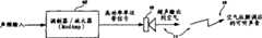
图1是根据本发明的实施例的功能框图,示出在一参量声音重放例子中的本发明的环境;Fig. 1 is a functional block diagram according to an embodiment of the present invention, showing the environment of the present invention in a parametric sound playback example;
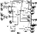
图2是本发明的一实施例的总的功能框图;Fig. 2 is a general functional block diagram of an embodiment of the present invention;
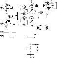
图3是示出关于图2所示的实施例的额外细节的最高级功能框图和示意图的组合图;FIG. 3 is a combined top-level functional block diagram and schematic diagram showing additional details regarding the embodiment shown in FIG. 2;
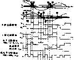
图4是一实施例中的三电平波形和经傅立叶级数展开后该三电平波形的频谱的图示;Fig. 4 is the illustration of the frequency spectrum of this tri-level waveform and the three-level waveform in one embodiment after Fourier series expansion;
图5中示出以功能框图形式示出的三电平脉冲发生器和示例波形的对照;A comparison of a three-level pulse generator and example waveforms shown in functional block diagram form is shown in FIG. 5;
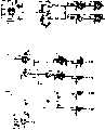
图6是示出一实施例中的测试装置的功能框图;Figure 6 is a functional block diagram illustrating a testing device in an embodiment;
图7中比较了由图6所示的测试装置生成的诸波形;Figure 7 compares the waveforms generated by the test setup shown in Figure 6;
图8中比较了图6所示装置的AM输出和SSB输出的频谱显示;The spectrum display of the AM output and the SSB output of the device shown in Fig. 6 is compared in Fig. 8;
图9中图示出如何使用正弦波以直接合成线性化的三电平脉冲波形并避免不得不在信号路径上设置反正弦函数硬件;Figure 9 illustrates how a sine wave can be used to directly synthesize a linearized three-level pulse waveform and avoid having to place arcsine function hardware on the signal path;
图10是多个波形的图示,示出了在本发明的一实施例中的三电平和两电平AM的正弦波合成;Figure 10 is a graphical representation of multiple waveforms showing sine wave synthesis of three-level and two-level AM in one embodiment of the invention;
图11是多个波形的图示,示出了在本发明的一实施例中的三电平和两电平SSB的正弦波合成;Figure 11 is a graphical representation of multiple waveforms showing sine wave synthesis of three-level and two-level SSB in one embodiment of the invention;
图12是一实施例中的事件发生器的更详细的示意框图;Figure 12 is a more detailed schematic block diagram of an event generator in one embodiment;
图13是一实施例中的AM调制器的更详细的示意框图;Figure 13 is a more detailed schematic block diagram of an AM modulator in one embodiment;
图14是一实施例中的SSB调制器的更详细的示意框图;Figure 14 is a more detailed schematic block diagram of an SSB modulator in one embodiment;
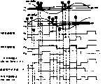
图15中比较了一实施例中的如图21所示的示例性ModAmp系统的时域和频域图;Figure 15 compares the time domain and frequency domain diagrams of the exemplary ModAmp system shown in Figure 21 in one embodiment;
图16中比较了一实施例中的如图21所示的示例性ModAmp系统的时域和频域图;Figure 16 compares the time domain and frequency domain plots of the exemplary ModAmp system shown in Figure 21 in one embodiment;
图17中比较了一实施例中的如图21所示的示例性ModAmp系统的时域和频域图;Figure 17 compares the time domain and frequency domain plots of the exemplary ModAmp system shown in Figure 21 in one embodiment;
图18中比较了一实施例中的如图21所示的示例性ModAmp系统的时域和频域图;Figure 18 compares the time domain and frequency domain plots of the exemplary ModAmp system shown in Figure 21 in one embodiment;
图19中比较了一实施例中的如图21所示的示例性ModAmp系统的时域和频域图;Figure 19 compares the time domain and frequency domain plots of the exemplary ModAmp system shown in Figure 21 in one embodiment;
图20中比较了一实施例中的如图21所示的示例性ModAmp系统的时域和频域图;Figure 20 compares the time domain and frequency domain diagrams of the exemplary ModAmp system shown in Figure 21 in one embodiment;
图21是示出一实施例中的ModAmp的示例性装置的最高级示意框图;Figure 21 is a top-level schematic block diagram illustrating an exemplary arrangement of ModAmp in one embodiment;
图22(a)和(b)分别是用于三角波和正弦波实施例中的电源抑制电路的示意框图;22(a) and (b) are schematic block diagrams of power suppression circuits used in triangular wave and sine wave embodiments, respectively;
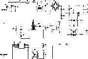
图23是一实施例中的调制器-放大器的示意图;Figure 23 is a schematic diagram of a modulator-amplifier in one embodiment;
图24是图23的续图;Figure 24 is a continuation of Figure 23;
图25中比较了一实施例中的ModAmp的诸波形;The waveforms of ModAmp in one embodiment are compared in FIG. 25;
图26是示出一实施例中的ModAmp的示例性装置的最高级示意框图;Figure 26 is a top-level schematic block diagram illustrating an exemplary arrangement of ModAmp in one embodiment;
图27是示出一实施例中的事件发生器的更详细的示意框图;Figure 27 is a more detailed schematic block diagram illustrating an event generator in one embodiment;
图28是示出一实施例中的AM调制器的更详细的示意框图;Figure 28 is a more detailed schematic block diagram illustrating an AM modulator in one embodiment;
图29是示出一实施例中的SSB调制器的更详细的示意框图Figure 29 is a more detailed schematic block diagram showing the SSB modulator in one embodiment
图30示出用于根据一实施例的仿真的设置的屏幕快照;Figure 30 shows a screenshot of the settings for a simulation according to an embodiment;
图31中比较了一实施例中的如图21所示的示例性ModAmp系统的时域和频域图;Figure 31 compares the time domain and frequency domain plots of the exemplary ModAmp system shown in Figure 21 in one embodiment;
图32(a)和(b)分别是用于三角波和正弦波实施例中的电源抑制电路的示意框图;32(a) and (b) are schematic block diagrams of power suppression circuits used in triangular wave and sine wave embodiments, respectively;
图33是示出一实施例中的一预处理器的框图;Figure 33 is a block diagram illustrating a pre-processor in one embodiment;
图34是示出一实施例中的系统的一动态范围压缩器的框图;Figure 34 is a block diagram illustrating a dynamic range compressor of the system in one embodiment;
图35是示出一实施例中的一动态载波控制器的框图;Figure 35 is a block diagram illustrating a dynamic carrier controller in one embodiment;
图36是一实施例中的一调制器-放大器的示意图;Figure 36 is a schematic diagram of a modulator-amplifier in one embodiment;
图37是图36的续图;Figure 37 is a continuation of Figure 36;
图38是图36和图37的续图;Figure 38 is a continuation of Figure 36 and Figure 37;
图39是图36-38的续图。Figure 39 is a continuation of Figures 36-38.
具体实施方式Detailed ways
现在将参照附图中示出的示例性实施例并使用特定语言描述该示例性实施例。然而,应理解本发明的内容并不由此受到限制。相关技术领域并拥有此公开的技术人员会想到的对这里描述的本发明特征的修改和进一步变型以及根据这里描述的本发明的原理进行的其他的应用,应理解为处在本发明的范围内。The exemplary embodiments will now be described with reference to the exemplary embodiments illustrated in the drawings and using specific language. However, it should be understood that the content of the present invention is not limited thereby. Modifications and further variations on the features of the invention described herein, as well as other applications in accordance with the principles of the invention described herein, will occur to those skilled in the relevant art and possessed of this disclosure, and are to be understood to be within the scope of the invention .
参照图1,其中示出ModAmp 10在参量阵11内的应用。一参量阵系统使用发射能量足够大的不可听的超声频率信号的换能器15在空气中生成可听声13。空气的非线性声学特性对该超声信号执行解调以生成该可听声。在通常的参量阵系统中,一超声载波信号由声频源调制,然后被放大并施加到高强度扬声器、发射器或换能器。这高强度超声波导致该发射器前面的空气呈现非线性传递特性。空气介质的非线性产生以和频和差频为形式的交调失真产物。其中的差频产生该可听声。例如,具有1KHz输入频率和40KHz载波频率的上边带调制器将在扬声器15中产生40KHz和41KHz的信号。非线性的空气柱解调将在阵11中生成1KHz的可听声。Referring to Fig. 1, the application of
参量阵11使用物理尺寸小的换能器15能够将声音指引或聚合成紧密的束。该参量阵概念可工作在包括例如空气的气体的流体中或工作在例如水的液体中。因为其小尺寸和高效率,该ModAmp是参量阵系统所需的调制和放大功能的理想解决方案。The parametric array 11 is able to direct or focus sound into a tight
其它的应用还包括各种应用中的AM和SSB发射机、SONAR信号调制和放大、医学超声波应用、频率变换放大器(frequency translatingamplifier)、带通放大器、正交相移键控和正交振幅调制。Other applications include AM and SSB transmitters in various applications, SONAR signal modulation and amplification, medical ultrasound applications, frequency translating amplifiers, bandpass amplifiers, quadrature phase shift keying, and quadrature amplitude modulation.
如图2所示,根据本发明的调制器-放大器系统(总体上由10指示)从声频源12获得声频信号,在声频信号预处理器14中可以一种或多种方式对该声频信号进行预处理,例如使信号预失真以矫正参量声音重放中固有的失真。声频信号输入16耦合到事件发生器18。该输入信号可以表示成同相(I)正弦信号和正交(Q)正弦信号。应理解该正交信号是基于I信号的余弦(相位偏离90°)信号。该事件发生器比较该输入信号和由参考信号发生器20产生的载波信号。As shown in FIG. 2, a modulator-amplifier system according to the present invention (generally indicated at 10) obtains an audio signal from an
应理解,提供了电源22,以根据各元件需要的电压和电流参数提供电能,下面将对此详细讨论。如下面将对此详细讨论的,可提供电力不足(brown-out)保护电路24,其中参考信号频率是基于在某频率上的墙上插座高电压交流源。It will be appreciated that a power supply 22 is provided to provide electrical power according to the voltage and current parameters required by the various components, as will be discussed in more detail below. As will be discussed in detail below, a brown-
如下面将进一步说明的,时间信号或脉冲由事件发生器18生成,并将这些信号以及由载波参考信号发生器生成的参考信号馈送到调制器/放大器开关输出驱动器级26。在那里根据事件发生器生成的脉冲对该载波信号进行调制。这可以这样进行,从而由SSB调制器部分28对载波进行SSB调制,或由AM调制器部分30对载波进行DSB调制。这是通过输出驱动器32中的状态开关实现的,下面将联系示例性实施例对所有这些进行更全面的讨论。还可以不对称地调制载波信号,这是通过在上边带和下边带上进行不等量的调制实现的。As will be explained further below, timing signals or pulses are generated by an
在载波频率的一些倍数上(例如载波频率的2、4倍)对信号进行开关调制,并将调制载波信号馈送到换能器34以在一介质中的参量阵36中重放来自声频源12的声频信号中的信息。来自该声频源的声频信号内的事件和输出驱动器32中的开关操作中的状态变化的发生之间存在一非线性关系,在一实施例中这种关系符合反正弦函数。事实表明,当利用这种关系时可以很好地解决特定的问题,使失真最小并且可以在输出开关中使用载波频率的较低倍数的频率。而且,对于将要讨论的不同的实例实现方式,在输出级中可以使用2态、3态、5态等状态开关。The signal is modulated on and off at some multiple of the carrier frequency (e.g. 2, 4 times the carrier frequency) and the modulated carrier signal is fed to the transducer 34 to reproduce the signal from the
声频输入信号与开关输出驱动器32内的状态变化的时间之间的非线性关系是传统的D类放大器所不具备的特征。所获得的优点并不是只有参量阵36内的参量声音重放应用才有的,但是在申请专利之时,到目前为止这种关系在参量技术中的应用是唯一的。The non-linear relationship between the audio input signal and the timing of state changes within the switching output driver 32 is a feature not found in conventional class D amplifiers. The advantages achieved are not unique to parametric sound playback applications within the parametric array 36, but at the time of the patent application, this relationship is so far unique in parametric technology.
现在参照图3,在一实施例中示意性地示出调制器-放大器10,其中示出一般化的ModAmp两电平SSB和DSB调制器/放大器的系统框图。在示出的例子中,输入是包含感兴趣的声频信息的正弦波形。通常使用预先录制的程序材料,但是实时馈入的声音也可以是感兴趣的信息。如下面进一步讨论的,该输入信号包括同相信号40和正交信号,将该些信号与参考信号比较并将其馈送到事件发生器18。根据输入信号和参考信号之间的非线性函数关系生成脉冲信号。将该脉冲信号或事件触发器馈送到一个或多个双边带(AM)调制器或SSB调制器,或馈送到另一种调制器。例如可在另一个实施例中使用如下面讨论的单边沿AM调制器44。在示出的实施例中提供了来自该些调制器的3电平和2电平输出。根据包含来自事件发生器的脉冲信号的事件触发器而在输出级内进行稳态之间的开关。如上提到的,提供了比较器来比较输入信号和参考信号并生成用于启动状态改变的脉冲。根据该开关模式是两电平还是三电平,对来自由电源22供电的参考信号发生器20的参考信号进行低-高或低-零-高调制以在AM输出46或SSB输出48生成位于超声频率的调制载波信号。将一常数50加到该振幅以便更好地与参量阵(未示出)中的一超声波换能器匹配。Referring now to FIG. 3, modulator-
使用此方法,可以使用输入信号16以各种方案——例如振幅调制(AM)和单边带调制(SSB)——对载波信号进行调制。调制器生成具有少量的离散输出振幅(或电压电平)的输出。通常使用2或3个离散输出电平。通过增加电压摆幅可以将调制器输出放大到任意电平。调制器输出的最简单形式是或者低或者高的二进制信号。可将这个二进制信号施加到MOSFET开关以增加电压摆幅从而增大或放大信号。使用这种开关技术可实现高效的功率调制器/放大器。在本白皮书中该组合调制器/放大器称为ModAmp。该ModAmp的输出频谱由所需的调制信号加上高频开关产物组成。在通常的应用中使用低通滤波器来消除高频开关产物。在调制器输出中不必须出现载波音调。AM或SSB信号可以有载波信号呈现或可以工作在抑制载波方式下。当载波受到抑制时,SSB ModAmp进行频率变换和放大。即ModAmp将输入信号进行频率偏移和放大。Using this method, the carrier signal can be modulated with the
参照图4,具有越来越宽的脉冲宽度的诸双向脉冲波形提供越来越强的基波振幅a1,该基波a1由下述方程(7)给出——。三电平波形的频谱由该基波和奇次谐波组成。通过改变如图4所示的该三电平信号的正脉冲宽度和负脉冲宽度,可以改变基波音调的强度a1。该三电平波形的脉冲宽度调制是在载波频率进行AM调制的有效方法。但首先应理解基波音调振幅如何随脉冲宽度变化。在下面的例子中得出基波和谐波音调的振幅。可见该三电平波形只生成基波和奇次谐波。这使第一个带外分量位于载波频率的3倍频率处。应注意所说明的波形是三电平波形,然而也可以使用两电平(二进制)波形。稍后将对此进行详细的讨论。如本领域内的技术人员可理解的,这些调制技术可以很容易地扩展到多电平信号(例如4电平、5电平)。Referring to FIG. 4 , bidirectional pulse waveforms with wider and wider pulse widths provide increasingly stronger fundamental amplitude a1 , which is given by equation (7 ) below - . The frequency spectrum of a three-level waveform consists of the fundamental and odd harmonics. By changing the positive pulse width and negative pulse width of the three-level signal as shown in FIG. 4 , the intensity a1 of the fundamental tone can be changed. Pulse width modulation of this three-level waveform is an efficient method for AM modulation at the carrier frequency. But first it is important to understand how the fundamental tone amplitude varies with pulse width. In the example below the amplitudes of the fundamental and tone are obtained. It can be seen that the three-level waveform generates only the fundamental and odd harmonics. This places the first out-of-band component at 3 times the carrier frequency. It should be noted that the illustrated waveforms are three-level waveforms, however two-level (binary) waveforms could also be used. This will be discussed in detail later. As those skilled in the art can understand, these modulation techniques can be easily extended to multi-level signals (eg, 4-level, 5-level).
输出信号的基波振幅是脉冲宽度参数的非线性函数。应记得具有周期T=1/f0的实数(real)周期信号可写为其傅立叶级数展开:The fundamental amplitude of the output signal is a nonlinear function of the pulse width parameter. It should be recalled that a real periodic signal with period T = 1/f0 can be written as its Fourier series expansion:
其中in
且and
及and
傅立叶系数an和bn分别表示构成周期信号(t)频谱的余弦和正弦信号的振幅。针对图4中的双向脉冲波形并使用(2)和(3),可得出基波和谐波声音的振幅为The Fourier coefficients an and bn represent the amplitudes of the cosine and sine signals, respectively, that make up the frequency spectrum of the periodic signal (t). Using (2) and (3) for the bidirectional pulse shape in Figure 4, the amplitudes of the fundamental and harmonic sounds are given as

和and
bn=0对于所有的n (6)bn = 0 for all n (6)
其中V是图4中标出的输出波形(或电源电压)的峰值。where V is the peak value of the output waveform (or supply voltage) marked in Figure 4.
特别感兴趣的是基波振幅a1是如何随脉冲宽度控制参数τ变化的。从(5)可见,基波振幅由下面的τ的非线性函数给出:Of particular interest is how the fundamental amplitude a1 varies with the pulse width control parameter τ. From (5), it can be seen that the fundamental amplitude is given by the following non-linear function of τ:
当τ=T/4时基波振幅具有最大峰值V(4/π)=V×1.273。这对应于方波输出信号。应注意载波频率处的输出电平可大于电源电压界限值V。When τ=T/4, the amplitude of the fundamental wave has a maximum peak value V(4/π)=V×1.273. This corresponds to a square wave output signal. It should be noted that the output level at the carrier frequency can be greater than the power supply voltage limit V.
如图5中所示,可以使用一三角波和两个比较器来生成三电平波形。该三角波可用于合成该三电平脉冲波形。可以对三电平脉冲发生器的输出直接过滤以产生一低电平的调制器输出,或者将其放大以产生高功率的调制器输出。从图中可见当比较器的阈值变量y从0变到1,τ将从T/4变到0,或表示为下式As shown in Figure 5, a tri-level waveform can be generated using a triangle wave and two comparators. The triangle wave can be used to synthesize the three-level pulse waveform. The output of the three-level pulse generator can be filtered directly to produce a low-level modulator output, or amplified to produce a high-power modulator output. It can be seen from the figure that when the threshold variable y of the comparator changes from 0 to 1, τ will change from T/4 to 0, or expressed as the following formula
假定要进行线性AM调制,即使得输出的基波音调振幅随某个输入变量或信号x线性变化(在0和其最大值4/π之间)。具体的,使基波的振幅为Assume that linear AM modulation is to be performed, that is, such that the output fundamental tone amplitude varies linearly (between 0 and its maximum value 4/π) with some input variable or signal x. Specifically, let the amplitude of the fundamental wave be
其中K是一常数(通常K=V)。如果K=V,则当x从0变到1时基波振幅将在0和其最大值V(4/π)之间变化。综合(7)、(8)和(9)可容易见到图5中的比较器的阈值变量y可表示成where K is a constant (usually K=V). If K=V, then the fundamental amplitude will vary between 0 and its maximum value V(4/π) as x changes from 0 to 1. Combining (7), (8) and (9), it can be easily seen that the threshold variable y of the comparator in Fig. 5 can be expressed as
方程式(10)是实现基波振幅随控制变量x线性变化的必要条件。当使用图5的线性脉冲宽度调制器时此方程式适用。方程式(10)是低失真AM和SSB调制的一必要(非充分)条件。应注意傅立叶级数展开给出的频谱只对周期信号有效,因此已假定脉冲宽度(和T)随时间保持恒定。此外,因为脉冲宽度和基波音调振幅的非线性关系,将声频信号输入一具有一三角波的输入比较器(一自然采样的双脉冲宽度发生器)时会导致输出频谱的重大失真。因此,必须用该反正弦函数使系统线性化。如果不对这个调制器例子实现反正弦函数则将导致失真。Equation (10) is a necessary condition to realize the linear variation of the fundamental wave amplitude with the control variable x. This equation applies when using the linear pulse width modulator of Figure 5. Equation (10) is a necessary (not sufficient) condition for low-distortion AM and SSB modulation. It should be noted that the spectrum given by Fourier series expansion is only valid for periodic signals, so it has been assumed that the pulse width (and T) remain constant over time. Furthermore, inputting an audio signal into an input comparator with a triangle wave (a naturally sampled dual pulse width generator) results in significant distortion of the output spectrum because of the non-linear relationship between pulse width and fundamental tone amplitude. Therefore, the system must be linearized with this arcsine function. Failure to implement the arcsine function for this modulator example will result in distortion.
下一步,使控制变量x随输入信号变化而不是保持恒定。这在载波频率f0处实现输入信号的AM调制。图6中用框图示出使用反正弦线性化电路和三角波比较器的AM和SSB调制器。该输入由两个正弦信号(一个位于2100KHz而另一个位于9300KHz)的和组成。下一步,将直流偏压/偏移加到该信号上,然后使该信号进入包括一反正弦函数的AM线性化电路。该三电平脉冲发生器使用一40KHz的三角波以生成AM输出。Next, make the control variable x vary with the input signal instead of being held constant. This achieves AM modulation of the input signal at carrier frequencyf0 . AM and SSB modulators using arcsine linearizers and triangular wave comparators are shown in block diagram in FIG. 6 . The input consists of the sum of two sinusoidal signals (one at 2100KHz and the other at 9300KHz). Next, a DC bias/offset is added to the signal, which is then passed to an AM linearizer that includes an arcsine function. The three-level pulse generator uses a 40KHz triangle wave to generate the AM output.
为了实现SSB调制,在该框图的下面的部分使用类似的信号处理路径,不同之处在于呈现的输入信号是正交的而且三角波信号移相90°。对于一般化输入信号可使用希耳伯特(Hilbert)变换以生成所需的分解信号(包括同相和正交分量)。这两个AM输出相减可获得下边带输出。而这两个AM输出相加可获得上边带输出。To implement SSB modulation, a similar signal processing path is used in the lower part of the block diagram, except that the input signals presented are in quadrature and the triangular wave signal is phase shifted by 90°. A Hilbert transform can be used for the generalized input signal to generate the desired decomposed signal (including in-phase and quadrature components). The two AM outputs are subtracted to obtain the lower sideband output. The two AM outputs are summed to obtain the upper sideband output.
图7中在一仿真输出的时域波形中示出了该AM和SSB调制器的波形。一般的,SSB波形可具有5个不同的振幅电平,这是因为SSB波形是两个三电平波形的和。然而,如果适当地设定调制器的偏移常数并且将输入信号电平限制到一特定值,则SSB输出将仅有三个电平。The waveforms of the AM and SSB modulators are shown in FIG. 7 in the time domain waveform of a simulated output. In general, an SSB waveform can have 5 different amplitude levels because the SSB waveform is the sum of two three-level waveforms. However, if the modulator's offset constant is set appropriately and the input signal level is limited to a certain value, the SSB output will only have three levels.
图8中示出AM和SSB输出的频谱。在AM输出频谱中载波频率是40KHz并在频谱的左部可以清楚地看到上侧音调和下侧音调。还可见中心位于载波的三倍频率(120KHz)的开关产物。通过一低通滤波器(未示出)可以滤除该开关产物。使模拟信号通过150KHz、8阶椭圆低通滤波器,在400KHz对该模拟信号进行采样并使用Hanning窗实现8192点的快速傅立叶变换(FFT),可以在仿真中生成该频谱显示。更高频率的开关产物也存在但在200KHz以上没有示出。频谱仅在150KHz内是精确的,因为在150KHz处该低通滤波器开始滚降(rolloff)。该滤波器防止FFT内发生混淆(aliasing)。The spectra of the AM and SSB outputs are shown in FIG. 8 . In the AM output spectrum the carrier frequency is 40KHz and the upper and lower tones can be clearly seen in the left part of the spectrum. Also visible are switching products centered at three times the frequency of the carrier (120KHz). The switching products can be filtered out by a low pass filter (not shown). Pass the analog signal through a 150KHz, 8th-order elliptic low-pass filter, sample the analog signal at 400KHz and use the Hanning window to realize the fast Fourier transform (FFT) of 8192 points, and the spectrum display can be generated in the simulation. Higher frequency switching products are also present but not shown above 200KHz. The spectrum is only accurate up to 150KHz because at 150KHz the low pass filter starts to roll off. This filter prevents aliasing within the FFT.
为了实现该ModAmp的功率放大部分,增大该开关输出波形到期望的振幅并使其通过一低通滤波器以减弱该高频开关分量。基于功率放大器的三电平SSB调制可使用H桥并适当地开关该桥的两个半桥以获得该三电平输出。下面详细给出使用此技术的ModAmp的例子。To implement the power amplification portion of the ModAmp, the switching output waveform is increased to a desired amplitude and passed through a low pass filter to attenuate the high frequency switching components. Power amplifier based three-level SSB modulation can use an H-bridge and switch the two half-bridges of the bridge appropriately to obtain the three-level output. An example of a ModAmp using this technique is given in detail below.
应注意该DC偏压设定该标称载波电平。在如下所述的一可选择的实施例中,操作中载波是被抑制的。It should be noted that the DC bias voltage sets the nominal carrier level. In an alternative embodiment as described below, the carrier is suppressed during operation.
现在介绍正弦波比较器,而在上面已计算了输入信号x的反正弦,所以当使用具有三角波输入的比较器(图5中示出的线性双脉冲宽度发生器)时可以实现线性运算。然而,可通过一不同的比较器结构使用正弦波信号而不是三角波信号来隐含地计算该反正弦。这样在信号路径上就不需要反正弦函数。使用图9中所示的正弦波参考振荡器可以直接合成线性化的三电平输出信号。这种情况中在正弦波的绝对值小于输入x的时间内生成脉冲。正弦波与该输入值相交的位置x定义了时刻t=τ,并且从该图中可推出如下公式,Now introducing the sine wave comparator, while above the arc sine of the input signal x has been calculated, so linear operation can be achieved when using a comparator with a triangular wave input (linear double pulse width generator shown in Figure 5). However, the arcsine can be computed implicitly using a sine wave signal instead of a triangle wave signal by a different comparator structure. This eliminates the need for an arcsine function in the signal path. The linearized three-level output signal can be directly synthesized using the sine wave reference oscillator shown in Figure 9. In this case pulses are generated during the time that the absolute value of the sine wave is less than the input x. The position x where the sine wave intersects this input value defines the instant t=τ, and from this figure the following formula can be deduced,
其中A是正弦波参考信号的振幅。where A is the amplitude of the sine wave reference signal.
解此方程求出τ并将其代入用于求解基波音调振幅的方程(7),可得到输入x和输出音调振幅之间的线性关系:Solving this equation for τ and substituting it into equation (7) for the fundamental tone amplitude yields a linear relationship between the input x and the output tone amplitude:
如果将A设为V/K则此方程与(9)相同。这里重要的一点是基波振幅是输入或控制变量x的线性函数。This equation is the same as (9) if A is set to V/K. The important point here is that the fundamental amplitude is a linear function of the input or control variable x.
参照图10现将讨论具有一H桥的三电平AM和SSB调制。在一个实施例中通过使用一H桥并适当地驱动两个半桥可以实现三电平AM。图10示出可用于生成该AM调制器输出的各种波形。可使用A和B“直接驱动”信号驱动H桥的两个半桥以实现三电平AM输出。可选择地,也可使用A′和B′信号中所示的“交错驱动”。通过在图10中标记的时间事件上触发状态转变可生成全部输出波形。对于三电平输出,必须适当地设置DC偏压并限制输入信号振幅。如果负载位于该H桥的中心,则两个半桥输出的差将给出期望的三电平AM输出信号。编号的方框标记出触发波形转变的时间事件。叠加一频率等于载波频率的方波可获得该两电平输出。Three-level AM and SSB modulation with an H-bridge will now be discussed with reference to FIG. 10 . Three-level AM can be achieved in one embodiment by using an H-bridge and appropriately driving the two half-bridges. Figure 10 shows various waveforms that can be used to generate the output of the AM modulator. The two half-bridges of the H-bridge can be driven using the A and B "direct drive" signals to achieve a three-level AM output. Alternatively, "interleaved drive" as shown in the A' and B' signals can also be used. All output waveforms are generated by triggering state transitions at the time events marked in FIG. 10 . For a three-level output, the DC bias must be set appropriately and the input signal amplitude limited. If the load is at the center of this H-bridge, the difference of the two half-bridge outputs will give the desired three-level AM output signal. Numbered boxes mark the time events that trigger waveform transitions. The two-level output is obtained by superimposing a square wave with a frequency equal to the carrier frequency.
图11示出了用于单边带(SSB)合成的信号。这种情况中,将正弦和余弦波与由同相XI分量和正交XQ分量(彼此相位偏离90°)组成的输入信号相比较。通常使用一Hilbert变换器获得该同相分量和正交分量。图中在该正弦波的过零点或该输入信号与该正弦波的交点定义了14个事件。示出两组可选择的H桥驱动信号:As,Bs和As′,Bs′。如果负载位于该H桥的中心,则两个半桥输出的差将给出期望的三电平SSB输出信号。再次使用编号的方框标记出触发波形转变的时间事件。叠加一频率等于载波频率的方波可获得该两电平输出。Figure 11 shows a signal for single sideband (SSB) synthesis. In this case, the sine and cosine waves are compared to an input signal consisting of an in-phase XI component and a quadrature XQ component (90° out of phase with each other). The in-phase and quadrature components are usually obtained using a Hilbert transformer. Fourteen events are defined in the figure at the zero crossing of the sine wave or at the intersection of the input signal and the sine wave. Two sets of selectable H-bridge drive signals are shown: As , Bs and As ′, Bs ′. If the load is at the center of this H-bridge, the difference of the two half-bridge outputs will give the desired three-level SSB output signal. Time events that trigger waveform transitions are again marked with numbered boxes. The two-level output is obtained by superimposing a square wave with a frequency equal to the carrier frequency.
再次参照图3的调制器/放大器的最高级框图,在一个实施例中生成的正弦输入测试信号是正交的,并且该信号驱动事件发生器模块18的实数输入和虚数(imaginary)输入。该事件发生器获得分别被AM调制器30和SSB调制器28使用的一系列14个短脉冲或事件触发器。下面详细说明事件发生器、AM和SSB调制器。Referring again to the top level block diagram of the modulator/amplifier of FIG. 3 , in one embodiment the generated sinusoidal input test signal is in quadrature and this signal drives the real and imaginary inputs of the
参照图12,当输入在示出的方向过零时每个过零检测器输出一短脉冲。在图中从上到下的事件触发器信号对应于图10和11中的方框中的事件标号。Referring to Figure 12, each zero crossing detector outputs a short pulse when the input crosses zero in the direction shown. The event trigger signals from top to bottom in the figure correspond to the event numbers in the boxes in FIGS. 10 and 11 .
参照图13,示出了可用于这里提出的ModAmp实施例的一实施例中的一DSB(AM)调制器。如图10所示,该些事件触发器使用交错驱动对正反器(flip-flop)60、62、64置位和复位以生成该三电平和两电平AM输出。Referring to Figure 13, there is shown a DSB (AM) modulator that may be used in one embodiment of the ModAmp embodiments presented herein. As shown in FIG. 10, the event flip-flops set and reset flip-flops 60, 62, 64 using interleaved driving to generate the three-level and two-level AM outputs.
参照图14,示出了可用于这里提出的ModAmp实施例的一实施例中的一SSB调制器。图11所示,该些事件触发器使用交错驱动对正反器70、72、74置位和复位以生成该三电平和两电平AM输出。Referring to Figure 14, there is shown an SSB modulator that may be used in one embodiment of the ModAmp embodiments presented herein. As shown in FIG. 11, the event flip-flops set and reset flip-flops 70, 72, 74 using interleaved driving to generate the three-level and two-level AM outputs.
应注意在调制器输出中不必须出现载波音调。AM或SSB信号可以有载波信号出现,或也可在抑制载波方式下工作。当使用该交错驱动时可将DC偏压电平设为零从而抑制载波。在抑制载波的情况中,根据交错驱动的边沿的时间顺序该三电平波形中的任何给定的脉冲可以是正向或负向的。在抑制载波的情况中,SSB ModAmp的功能类似一频率变换“带通”放大器。即该ModAmp频率使输入频谱变换到由载波频率确定的某个其它的频带。It should be noted that the carrier tone does not have to be present at the modulator output. AM or SSB signals can have a carrier signal present, or work in a suppressed carrier mode. When using this interleaved drive the DC bias level can be set to zero to suppress the carrier. In the case of suppressed carriers, any given pulse in the three-level waveform can be positive going or negative going depending on the time sequence of the interleaved driven edges. In the case of suppressed carriers, the SSB ModAmp functions like a frequency translating "bandpass" amplifier. That is, the ModAmp frequency transforms the input spectrum to some other frequency band determined by the carrier frequency.
对于一个实施例中的准确的二进制输出,希望输出仅有两电平。通过叠加一频率等于载波频率的方波(它将改变该三电平输出的载波电平)可以将该三电平AM和SSB波形转变成两电平波形。然而可以改变DC偏压以允许进行具有或不具有抑制载波的两电平操作。该两电平输出信号允许使用仅需两个输出晶体管的一个半桥(而不是整个H桥)来构建一个放大器。通过适当设置DC偏压也可以使得该两电平调制器的操作具有抑制载波。图15-20示出来自一一般化的ModAmp系统的几个实例仿真结果。图21中示出了所使用的一测试装置。图15-20中示出的时域和频域结果由图21所示的测试ModAmp系统生成。这些图中示出了时域图和频域图以便于比较。For an exact binary output in one embodiment, it is desirable that the output have only two levels. The three-level AM and SSB waveforms can be converted to two-level waveforms by superimposing a square wave with a frequency equal to the carrier frequency (which changes the carrier level of the three-level output). However the DC bias can be varied to allow two level operation with or without suppressed carrier. The two-level output signal allows an amplifier to be built using a half-bridge (rather than a full H-bridge) requiring only two output transistors. The operation of the two-level modulator with suppressed carrier can also be made by properly setting the DC bias voltage. 15-20 show several example simulation results from a generalized ModAmp system. A test setup used is shown in FIG. 21 . The time domain and frequency domain results shown in Figures 15-20 were generated by the test ModAmp system shown in Figure 21. Time domain plots and frequency domain plots are shown in these figures for comparison.
图15示出具有抑制载波的三电平AM。将DC偏移常数设为零以抑制该载波。图16中示出图21的系统中的三电平SSB调制的时域和频域结果。在这个下边带调制器例子中将DC偏移常数设为零再次抑制了该载波。时域图示出正弦和余弦参考波形以及同相和正交输入信号。图17示出具有抑制载波的两电平AM。在这个例子中将DC偏移常数设为0.5以在二进制波形中实现抑制载波,该二进制波形显示在底部的时域波形中。图18示出具有抑制载波的两电平SSB调制情况。在图21的系统中将DC偏移常数设为0.35353535。图19中比较了具有载波的三电平AM调制器(顶部频谱)和两电平AM调制器(底部频谱)。将DC偏移常数设为0.255,以在两种情况中实现同样的基带频谱。应注意两电平调制器实施例中的载波的三次谐波(位于120KHz)较大。图20中的示例性仿真比较了具有载波的三电平SSB调制器(顶部)和两电平SSB调制器(底部)。将DC偏移常数设为0.17676767。应注意此实施例中两电平调制器的载波的三次谐波(位于120KHz)较小而不是较大。Figure 15 shows a three-level AM with suppressed carrier. Set the DC offset constant to zero to suppress this carrier. The time domain and frequency domain results of the three-level SSB modulation in the system of FIG. 21 are shown in FIG. 16 . Setting the DC offset constant to zero in this lower sideband modulator example again suppresses the carrier. The time domain plot shows the sine and cosine reference waveforms and the in-phase and quadrature input signals. Figure 17 shows two-level AM with suppressed carrier. In this example set the DC offset constant to 0.5 to achieve suppressed carrier in the binary waveform shown in the time domain waveform at the bottom. Figure 18 shows the two-level SSB modulation case with suppressed carrier. The DC offset constant is set to 0.35353535 in the system of FIG. 21 . A three-level AM modulator with a carrier (top spectrum) and a two-level AM modulator (bottom spectrum) are compared in Figure 19. The DC offset constant was set to 0.255 to achieve the same baseband spectrum in both cases. It should be noted that the third harmonic of the carrier (at 120KHz) is larger in the two-level modulator embodiment. The example simulation in Figure 20 compares a three-level SSB modulator with a carrier (top) and a two-level SSB modulator (bottom). Set the DC offset constant to 0.17676767. Note that the third harmonic (at 120KHz) of the carrier of the two-level modulator in this embodiment is smaller rather than larger.
参照图3和21,提到一可选择的单边沿调制,并可以提供这样的调制器(每个图中的44)。上面确定的三电平AM和SSB调制器输出波形具有前沿调制和后沿调制两者。一种另外的方法是单边沿调制。例如,可以合成具有固定前沿(在正弦波的过零点)的三电平AM信号,并仅调制后沿的时间。通过叠加一频率等于载波频率的方波,可以将这个单边沿调制AM波形转变成一两电平波形。这种波形的一个好处是它只有两个转变/周期(而不是标准的两电平AM的6个)。这种方法的一个缺点是在被调制的输出信号中有频谱失真。Referring to Figures 3 and 21, an optional single edge modulation is mentioned and such a modulator (44 in each figure) may be provided. The three-level AM and SSB modulator output waveforms identified above have both leading edge and trailing edge modulation. An additional method is single edge modulation. For example, it is possible to synthesize a three-level AM signal with a fixed leading edge (at the zero crossing of the sine wave) and only modulate the time of the trailing edge. This single-edge-modulated AM waveform can be converted into a two-level waveform by superimposing a square wave with a frequency equal to the carrier frequency. One benefit of this waveform is that it only has two transitions/cycle (instead of 6 for standard two-level AM). A disadvantage of this approach is spectral distortion in the modulated output signal.
以此讨论为背景,表1总结了各种调制器的特性。假定一个H桥需要4个MOSFET而一个半桥需要2个MOSFET。“每载波周期的转变”表明在每个载波周期内调制器输出的信号转变数。通常,转变越少放大器的效率越高。With this discussion as background, Table 1 summarizes the characteristics of the various modulators. Assume that an H-bridge requires 4 MOSFETs and a half-bridge requires 2 MOSFETs. "Transitions per carrier period" indicates the number of signal transitions output by the modulator within each carrier period. In general, amplifiers with fewer transitions are more efficient.
表1中的第5项使用两个两电平AM调制器并利用它们的差合成SSB输出。第6项以“两电平AM”开始并叠加一频率为载波的三次谐波的方波。这是用于减少调制器输出中的三次谐波的振幅。在更高次谐波进行叠加的方案也是可行的。第7项以“三电平AM”开始并叠加一频率为载波的三次谐波的方波。第8项组合两个“三次谐波降低的两电平AM”(第6项)以合成该SSB输出。Item 5 in Table 1 uses two two-level AM modulators and uses their difference to synthesize the SSB output. Item 6 begins with "two-level AM" and superimposes a square wave whose frequency is the third harmonic of the carrier. This is used to reduce the amplitude of the third harmonic in the modulator output. A scheme of superposition at higher harmonics is also feasible. Item 7 begins with "Tri-Level AM" and superimposes a square wave whose frequency is the third harmonic of the carrier. Item 8 combines the two "3rd Harmonic Reduced Two-Level AM" (Item 6) to synthesize the SSB output.
表1各种调制器的特性
除非明确地实施由方程(10)提出的前馈技术,否则ModAmp的输出电压电平将与电源电压成比例。仿真中假设电源电压是恒定的电压1。然而,如果修改该ModAmp以监视电源电压并调整脉冲宽度,则它们将自动补偿电源电压的变化和噪声(例如120Hz或其它交流线谐波)。Unless the feedforward technique proposed by equation (10) is explicitly implemented, the output voltage level of the ModAmp will be proportional to the supply voltage. The power supply voltage is assumed to be a
可使用一根据电源电压的变化而改变脉冲宽度的前馈技术来实现电源抑制。从(10)中可见看在进行反正弦之前用K/V乘以了x。在迄今的系统仿真中已假设K=1、V=1。随着电源电压V的改变可适当地调整脉冲宽度以保持一致的输出。Power supply rejection can be achieved using a feed-forward technique that varies the pulse width in response to changes in supply voltage. It can be seen from (10) that x is multiplied by K/V before arcsine is performed. K=1, V=1 have been assumed in previous system simulations. As the supply voltage V changes, the pulse width can be adjusted appropriately to maintain a consistent output.
图22(a)示出一具有电源抑制的系统,当使用基于三角波的三电平脉冲发生器时在该系统中显性地实现了方程(10)。对于正弦波三电平脉冲发生器可获得另外一种实现。图22(b)示出一正弦波参考信号的振幅与电源电压按比例变化的系统。为了了解其工作原理,将正弦波振幅参数设为Figure 22(a) shows a system with power supply rejection in which Equation (10) is explicitly implemented when using a triangular wave based three-level pulse generator. Another implementation is available for a sinusoidal three-level pulse generator. Fig. 22(b) shows a system in which the amplitude of the sine wave reference signal varies proportionally to the supply voltage. To see how this works, set the sine wave amplitude parameter to
将其代入(12)中。获得独立于电源电压的输出振幅。具体地,得到所需的线性关系:Substitute it into (12). Obtain an output amplitude independent of supply voltage. Specifically, the desired linear relationship is obtained:
通过使用上述的前馈电源抑制技术中的一个,可以无需使用通常需要的稳压电源。By using one of the feed-forward power supply rejection techniques described above, the normally required regulated power supply can be eliminated.
该调制器-放大器的一示例性的实施例进行三电平单边带调制。图23和24中示出带注释的示意图。使用比较器U1实现主时钟振荡器。振荡器运行的频率是载波频率的4倍。一由两个D型正反器组成的简单状态机生成一对频率为载波频率的正交的方波。使用两个4阶低通滤波器滤除该方波的谐波并留下近乎纯的正弦音调。结果是正弦和余弦载波参考信号。An exemplary embodiment of the modulator-amplifier performs three-level single sideband modulation. Annotated schematics are shown in FIGS. 23 and 24 . The main clock oscillator is implemented using comparator U1. The oscillator runs at 4 times the carrier frequency. A simple state machine consisting of two D-type flip-flops generates a pair of square waves in quadrature at the carrier frequency. Two 4th order low pass filters are used to filter out the harmonics of this square wave and leave a nearly pure sine tone. The result is a sine and cosine carrier reference signal.
该ModAmp的输入由同相和正交(Iin和Qin)声频信号组成。输入运算放大器放大并硬限制该输入信号。该运算放大器的输出电压被限制在0V和+5V的电源电压界限值。这个限幅器限制了该三电平SSB信号的最大脉冲宽度。在经过一增益微调电位器(trimming pot)后,该声频信号与一1uF电容器交流耦合。然后添加一DC偏压以设置载波电平。将这个信号馈入上部的比较器U2,并将该信号的反相复本馈入下部的比较器U3。The input to the ModAmp consists of in-phase and quadrature (Iin and Qin ) audio signals. The input op amp amplifies and hard limits this input signal. The output voltage of this operational amplifier is limited to the supply voltage limits of 0V and +5V. This limiter limits the maximum pulse width of the tri-level SSB signal. After passing through a gain trimming pot, the audio signal is AC-coupled with a 1uF capacitor. A DC bias is then added to set the carrier level. This signal is fed into the upper comparator U2 and an inverted copy of this signal is fed into the lower comparator U3.
这些比较器的输出被馈送到一边沿检测器电路,该电路在正向的和负向的比较器转变上生成一短的250ns脉冲。这些“事件触发器”信号用于设置和清除该H桥的A半桥和B半桥。The output of these comparators is fed to an edge detector circuit which generates a short 250 ns pulse on positive and negative going comparator transitions. These "event trigger" signals are used to set and clear the A and B half bridges of that H bridge.
该示意图的第二页上示出使用MOSFET的一互补对以缓冲(并反相)该事件触发器脉冲。该主MOSFET是由一使用小脉冲变压器和一对小MOSFET以生成主栅驱动信号的新型电路设计驱动的。不考虑细节,该驱动器电路使用短的置位和清除脉冲来为该主MOSFET生成两极栅驱动信号。该驱动器设计避免了MOSFET的交叉传导(cross conduction)(或击穿(shoot through))并能够在宽的占空比范围上工作。The second page of the schematic shows the use of a complementary pair of MOSFETs to buffer (and invert) the event trigger pulse. The main MOSFET is driven by a novel circuit design using a small pulse transformer and a pair of small MOSFETs to generate the main gate drive signal. Without going into details, the driver circuit uses short set and clear pulses to generate bipolar gate drive signals for the main MOSFET. The driver design avoids MOSFET cross conduction (or shoot through) and is capable of operating over a wide range of duty cycles.
输出负载连接到两个半桥之间以提取SSB输出。在这种情况中,一串联电感形成低通滤波器。通过对120V交流线电压全波整流并用电容滤波来获得用于输出级的高电压电源。表2中给出了ModAmp原型的规格。The output load is connected between the two half-bridges to extract the SSB output. In this case, a series inductor forms a low pass filter. The high-voltage power supply for the output stage is obtained by full-wave rectification of the 120V AC line voltage and filtering with capacitors. The specifications of the ModAmp prototype are given in Table 2.
表2:ModAmp实例规格Table 2: ModAmp Instance Specifications
输出功耗:200wOutput power consumption: 200w
效率:95-98%Efficiency: 95-98%
交调失真:0.4%(1KHz输入产生39KHz和40KHz输出,在DC-60KHz范围上测量失真)Intermodulation distortion: 0.4% (1KHz input produces 39KHz and 40KHz output, distortion is measured on the range of DC-60KHz)
应注意电路设计使部件数量最少;Care should be taken in circuit design to minimize the number of components;
输入电源:120V ACInput power: 120V AC
物理尺寸:ModAmp:1.9×3.8×0.3英寸Physical Dimensions: ModAmp: 1.9 x 3.8 x 0.3 inches
电源和匹配网络:1.9×3.8×1.2英寸Power supply and matching network: 1.9×3.8×1.2 inches
应注意关于这里提出的上述调制器输出频谱,对于所有讨论的调制方法(假定正弦波输入)都可获得调制器输出频谱的闭式解析表达式。It should be noted that with respect to the above modulator output spectrum presented here, closed-form analytical expressions for the modulator output spectrum are available for all modulation methods discussed (assuming sinusoidal input).
至此已假设使用诸如三角波振荡器、正弦波振荡器和比较器等模拟元件来实现ModAmp。然而,假设具有数字(脉冲编码调制(PCM))输入信号则在数字领域中实现所有的调制操作是可行的。So far it has been assumed that the ModAmp is realized using analog components such as a triangle wave oscillator, a sine wave oscillator, and a comparator. However, it is feasible to implement all modulation operations in the digital domain assuming a digital (Pulse Code Modulation (PCM)) input signal.
数字ModAmp的实现如下:(1)对输入PCM波形进行上采样(up-sample),(2)比较该上采样输入与一数字合成的正弦波,以及(3)使用该比较器的输出以生成用于MOSFET功率开关的驱动信号。这个问题可简化成寻找该过采样的或内插的PCM波形的过零次数(与图11的模拟事件发生器类似)。为了精确计算过零次数而不使用过高的采样率,可以使用求根方法(例如牛顿法)。A digital ModAmp is implemented by (1) up-sampling the input PCM waveform, (2) comparing the up-sampled input to a digitally synthesized sine wave, and (3) using the output of the comparator to generate Drive signal for MOSFET power switches. This problem can be reduced to finding the number of zero crossings of the oversampled or interpolated PCM waveform (similar to the analog event generator of Figure 11). In order to accurately calculate the number of zero crossings without using an excessively high sampling rate, a root-finding method (such as Newton's method) can be used.
一旦计算出了过零次数,则数字PWM逻辑可生成输出波形。如果在边沿上需要高精度的时间分辨率,则数字PWM将需要极高的时钟速率。为了缓解对过高时钟速率的需要,可应用例如噪声整形(noise shaping)的技术以抖动(dither)边沿时间(例如Delta Sigma调制)。Once the number of zero crossings has been counted, the digital PWM logic can generate the output waveform. If high precision time resolution is required on the edges, digital PWM will require extremely high clock rates. To alleviate the need for an excessively high clock rate, techniques such as noise shaping can be applied to dither the edge timing (eg Delta Sigma modulation).
在一实施例中也可以有一多相位变型。可以将多个ModAmp并行以降低输出波纹电压并增加功率。每个放大器工作在比前一个放大器稍微超前的相位上。例如通过该输出滤波器电感将该些“交错相位”ModAmp的输出叠加在一起。使用这种多相位方法,也可能增加带外分量的频率,从而减小后滤波的需求。In one embodiment there may also be a multi-phase variant. Multiple ModAmps can be paralleled to reduce output ripple voltage and increase power. Each amplifier operates at a slightly advanced phase than the previous amplifier. The outputs of the "interleaved phase" ModAmps are summed together, for example through the output filter inductance. Using this polyphase approach, it is also possible to increase the frequency of out-of-band components, thereby reducing the need for post-filtering.
一FM调制器变型也是另一个可能的实施例。使用与AM调制方案相同的元件并进行如下修改可实现该ModAmp的FM调制器方案。首先,将对ModAmp的输入设为常数。这样可获得一恒定的载波输出。其次,用一压控振荡器(VCO)替换该振荡器(根据该ModAmp的三角波或正弦波振荡器)。最后将该VCO的控制输入用作调制器输入。An FM modulator variant is also another possible embodiment. The ModAmp's FM modulator scheme can be implemented using the same components as the AM modulation scheme with the following modifications. First, set the input to ModAmp as a constant. In this way a constant carrier output can be obtained. Second, replace the oscillator (triangular wave or sine wave oscillator according to the ModAmp) with a voltage controlled oscillator (VCO). Finally the control input of this VCO is used as the modulator input.
应注意,不是必须使用一AM线性化电路(因为使用直流信号作为输入)或一个正弦波振荡器。只需产生将在基频上形成载波音调的三电平或两电平波形。该VCO进行FM调制,比较器生成开关信号,并且MOSFET开关对波形放大。结果是一FM ModAmp。此外,这个基本原理可扩展到其它的调制方法,例如正交相移键控(QPSK)、正交振幅调制(QAM)等。It should be noted that it is not necessary to use an AM linearizer (since a DC signal is used as input) or a sine wave oscillator. Simply generate a three-level or two-level waveform that will form a carrier tone at the fundamental frequency. The VCO performs FM modulation, the comparator generates the switching signal, and the MOSFET switches amplify the waveform. The result is an FM ModAmp. In addition, this basic principle can be extended to other modulation methods, such as quadrature phase shift keying (QPSK), quadrature amplitude modulation (QAM) and so on.
现在将讨论更多的实施例,并将包括一些先前的讨论的重复。然而,通过下面的讨论将获得对本发明另外的理解。More embodiments will now be discussed, and some repetitions of previous discussions will be included. However, an additional understanding of the invention will be gained through the following discussion.
参照图25,信号用于单边带(SSB)合成。在这种情况中,将正弦和余弦波与由同相和正交分量(彼此之间相位偏离90°)组成的输入信号相比较。通常使用一Hilbert变换器获得该同相和正交分量。图中在输入信号和正弦波的交点或正弦波的过零点确定了14个事件。Referring to Figure 25, the signal is used for single sideband (SSB) synthesis. In this case, the sine and cosine waves are compared to an input signal consisting of in-phase and quadrature components (90° out of phase with each other). The in-phase and quadrature components are usually obtained using a Hilbert transformer. Fourteen events are identified in the figure at the intersection of the input signal and the sine wave or at the zero crossing of the sine wave.
图26示出另一个实施例中的调制器/放大器的最高级框图。图27中详细示出,产生的正弦输入测试信号是正交的并驱动该事件发生器块的实数和虚数输入。该事件发生器获得由该AM和SSB使用的一系列14个短脉冲或事件触发器。图28和29中分别详细示出了该AM和SSB调制器。Figure 26 shows a top level block diagram of a modulator/amplifier in another embodiment. As detailed in Figure 27, the generated sinusoidal input test signals are in quadrature and drive the real and imaginary inputs of the event generator block. The event generator gets a series of 14 short pulses or event triggers used by the AM and SSB. The AM and SSB modulators are shown in detail in Figures 28 and 29, respectively.
对于二进制输出,我们希望该输出仅有两个电平。通过叠加一频率为载波频率的方波可以将该三电平AM和SSB波形转变成两电平波形,如在图25的底部所示。可选择地,在图1中标注为As′的两电平信号(粗线波形)产生所需的SSB输出。该两电平输出信号允许使用一仅需两个输出晶体管的半桥(而不是一全H桥)构建一放大器。For a binary output, we want the output to have only two levels. The three-level AM and SSB waveforms can be converted to two-level waveforms by superimposing a square wave at the carrier frequency, as shown at the bottom of FIG. 25 . Alternatively, a two-level signal (thick line waveform) labeled As' in Figure 1 produces the desired SSB output. The two-level output signal allows the construction of an amplifier using a half-bridge requiring only two output transistors (instead of a full H-bridge).
使用图30所示的参数设置可运行具有两个测试音调的仿真。图31的顶部示出三电平和As′-两电平调制的时域波形。图31的余下部分示出这两种情况的频谱。应注意该As′-两电平调制具有中心在80KHz附近的带外信号。因为在我们的应用中使用的PVDF换能器在55KHz以上的频率几乎没有输出,因此在该模拟ModAmp中使用该简单的As′-两电平调制方法。A simulation with two test tones was run using the parameter settings shown in Figure 30. The top of Figure 31 shows the time-domain waveforms for three-level andAs' -two-level modulation. The remainder of Figure 31 shows the spectra for these two cases. Note that theAs' -two-level modulation has an out-of-band signal centered around 80 KHz. Since the PVDF transducer used in our application has almost no output at frequencies above 55KHz, the simpleAs' -two-level modulation method is used in the analog ModAmp.
在该模拟ModAmp中使用图32(b)的电源噪声/波纹抑制方法。在本发明的公开文件中已示出,如果控制参考振荡器的振幅使之与MOSFET的电源电压成比例,则可获得与该电源电压无关的输出。The power supply noise/ripple suppression method of Fig. 32(b) is used in this simulated ModAmp. It has been shown in the present disclosure that if the amplitude of the reference oscillator is controlled to be proportional to the power supply voltage of the MOSFET, an output independent of the power supply voltage can be obtained.
表3总结了各种调制器的特性。假定一H桥需要4个MOSFET而一半桥需要2个MOSFET。“每载波周期的转变”表示在每个载波周期内调制器输出的信号转变数。通常,转变越少放大器的效率越高。第5项使用两个两电平AM调制器并利用它们的差合成SSB输出。第6项以“两电平AM”开始并叠加一频率为载波的三次谐波的方波。这样可降低该调制器输出中的三次谐波的振幅。叠加更高次谐波的方法也是可行的。第7项以“三电平AM”开始并叠加一频率等于载波的三次谐波的方波。第8项组合两个“三次谐波降低的两电平AM”(第6项)以合成该SSB输出。第9项是此文件中所述的模拟ModAmp使用的新技术。Table 3 summarizes the characteristics of the various modulators. Assume that an H bridge requires 4 MOSFETs and a half bridge requires 2 MOSFETs. "Transitions per carrier period" means the number of signal transitions output by the modulator within each carrier period. In general, amplifiers with fewer transitions are more efficient. Item 5 uses two two-level AM modulators and uses their difference to synthesize the SSB output. Item 6 begins with "two-level AM" and superimposes a square wave whose frequency is the third harmonic of the carrier. This reduces the amplitude of the third harmonic in the modulator output. A method of superimposing higher harmonics is also possible. Item 7 begins with "Tri-Level AM" and superimposes a square wave with a frequency equal to the third harmonic of the carrier. Item 8 combines the two "3rd Harmonic Reduced Two-Level AM" (Item 6) to synthesize the SSB output. Item 9 is a new technology used by the simulated ModAmp described in this document.
表3
关于用于该模拟ModAmp的预处理软件,在一计算机上对源声频材料进行处理以生成分别保存在MP3播放器的右声道和左声道上的I(同相)和Q(正交)信号。该软件用MATLAB/Simulink写成并且在图33、34和35中示出其框图。Regarding the pre-processing software used in this analog ModAmp, the source audio material is processed on a computer to generate I (in-phase) and Q (quadrature) signals which are stored on the right and left channels of the MP3 player respectively . The software is written in MATLAB/Simulink and its block diagrams are shown in FIGS. 33 , 34 and 35 .
在另一实施例中,在图36-39中示出一模拟ModAmp电路的描述。此放大器从一MP3播放器中接收模拟的I和Q信号。这些信号是DC耦合的从而该预处理器软件输出可以动态控制该载波电平。必须使用保持DC项的MP3播放器。对于此应用选择三星YP-30S。设计并构建进行两电平下边带调制的模拟ModAmp。在下面的段落中说明这个电路。In another embodiment, a depiction of an analog ModAmp circuit is shown in FIGS. 36-39. This amplifier receives analog I and Q signals from an MP3 player. The signals are DC coupled so that the pre-processor software output can dynamically control the carrier level. An MP3 player that maintains the DC entry must be used. For this application select Samsung YP-30S. Design and build an analog ModAmp with two-level lower sideband modulation. This circuit is illustrated in the following paragraphs.
在图36的示意图中示出电源。该高电压电源是一由EMI滤波元件、一全波桥整流器和滤波电容器组成的简单的离线电源。该高压电源为主MOSFET和辅助电源供电。该辅助电源为该ModAmp的控制电路和该MP3播放器提供5V电压。它是基于Power Integrations的TNY264回扫调节器芯片的。这个芯片封装了用于完整的与变压器隔离的回扫电源的所有控制逻辑和主开关。The power supply is shown in the schematic diagram of FIG. 36 . The high voltage power supply is a simple off-line power supply consisting of EMI filter elements, a full-wave bridge rectifier and filter capacitors. This high voltage supply powers the main MOSFETs and auxiliary supplies. The auxiliary power supply provides 5V voltage for the control circuit of the ModAmp and the MP3 player. It is based on the TNY264 flyback regulator chip from Power Integrations. This chip encapsulates all the control logic and main switches for a complete transformer-isolated flyback power supply.
正弦/余弦参考振荡器的实现如下:在图37中主时钟振荡器是LTC1799芯片U5。电感器L7确保振荡噪声没有传导进该5V电源。该振荡器的运行频率是载波频率的4倍。一由两个D型正反器U6组成的简单状态机生成频率为载波频率的一对正交的方波。使用两个由U7、U8和相关联的R′s和C′s组成的4阶Chebyshev低通滤波器滤除该方波的谐波并剩下几乎是纯的正弦音调。其结果是正弦和余弦载波参考信号。隔直电容器C17和C25用于消除在该滤波器内的累积的偏移误差。一最终增益级U9用于提高信号电平。The sine/cosine reference oscillator is implemented as follows: In Figure 37 the master clock oscillator is the LTC1799 chip U5. Inductor L7 ensures that ringing noise is not conducted into the 5V supply. This oscillator runs at 4 times the carrier frequency. A simple state machine consisting of two D-flip-flops U6 generates a pair of quadrature square waves at the carrier frequency. The harmonics of this square wave are filtered out using two 4th order Chebyshev low pass filters consisting of U7, U8 and associated R's and C's leaving an almost pure sinusoidal tone. The result is a sine and cosine carrier reference signal. DC blocking capacitors C17 and C25 are used to cancel accumulated offset errors within the filter. A final gain stage U9 is used to increase the signal level.
在图37的下半部中的由U10和U11组成的电路是电源抑制电路。这些电路在该D型正反器上强加了一与该高电压电源成比例的对称电源电压。因为D型正反器的输出是在两界限值之间摆动的,所以该正交方波输出的振幅与该高电源电压成比例。最后,如所需的,该正弦和余弦输出的振幅与该高电源电压成比例。The circuit consisting of U10 and U11 in the bottom half of Figure 37 is a power supply suppression circuit. These circuits impose a symmetrical supply voltage on the D-flip-flop proportional to the high voltage supply. Since the output of the D-flip-flop is swinging between two thresholds, the amplitude of the quadrature square wave output is proportional to the high supply voltage. Finally, the amplitudes of the sine and cosine outputs are proportional to the high supply voltage, as desired.
设置该电路增益从而输出正弦波在该高输入线电压时将受到削波。这种削波没有负面后果,因为后续的比较器电路并没有使用该波形的峰值。设计中增大的振幅会增加总的动态范围。The circuit gain is set so that the output sine wave will be clipped at this high input line voltage. This clipping has no negative consequences because the peak of the waveform is not used by the subsequent comparator circuit. Increased amplitude in the design increases the overall dynamic range.
在一实施例中可提供一复位/电力不足保护电路。该复位芯片U22在加电时触发一2秒激活的低复位脉冲。如果该VCC输入降低到4.00V以下则也会执行复位。在电源示意图36中,该RESET_F信号当激活时通过开关Qa中断对该主MOSFET的高电压供电。使用该系统以延迟该主MOSFET的加电,直到该5V电源已稳定并且该MOSFET的驱动信号有效。在交流线电压低于大约80V AC的电力不足条件下,这个电路也可关断对MOSFET的电源供电。当高电压降低时,该设计通过使用二极管D4拉低该复位芯片的VCC输入来进行电力不足复位。这个复位行为是重要的,因为该正弦波参考信号与该高电压成比例,并且降低的参考信号将最终导致比较器输出无效的控制波形。In one embodiment, a reset/brownout protection circuit may be provided. The reset chip U22 triggers a 2 second active low reset pulse on power up. A reset is also performed if the VCC input drops below 4.00V. In power schematic 36, the RESET_F signal, when active, interrupts the high voltage supply to the main MOSFET through switchQa . This system is used to delay power-up of the main MOSFET until the 5V supply has stabilized and the drive signal to the MOSFET is valid. This circuit also shuts down the power supply to the MOSFET during brownout conditions where the AC line voltage is below approximately 80V AC. The design does a brownout reset by using diode D4 to pull down the VCC input of the reset chip when the high voltage drops. This reset behavior is important because the sine wave reference signal is proportional to the high voltage, and a reduced reference signal will eventually cause the comparator to output an invalid control waveform.
该ModAmp的输入由同相和正交声频信号以及控制该载波水平的DC组成。图14中的电路U12、U17和U14B获得该MP3播放器的输入并生成一硬限制(0到5V)的信号,该信号在没有输入信号时标称为+5V/2(2.5V)。在这一级中削除过量的输入电平对于避免后续电路中出现无效的比较器输出是至关重要的。The input to the ModAmp consists of in-phase and quadrature audio signals and DC to control the carrier level. Circuits U12, U17 and U14B in FIG. 14 take the input from the MP3 player and generate a hard-limited (0 to 5V) signal that is nominally +5V/2 (2.5V) when there is no input signal. Clipping excess input levels at this stage is critical to avoid invalid comparator outputs in subsequent circuits.
该运算放大器电路设计从该MP3播放器输出中获得比率度量(ratiometric)信号(播放器中的该DAC与该2.47V参考电压和该数字编码的乘积成比例)并生成一输出,该输出随该载波电平的增加而降低到额定的2.5V以下。设计该电路以消除通常随+5V电源变化而产生的偏移电压误差。The operational amplifier circuit design takes a ratiometric signal from the MP3 player output (the DAC in the player is proportional to the product of the 2.47V reference voltage and the digital code) and generates an output that follows the The increase of the carrier level decreases below the rated 2.5V. The circuit is designed to eliminate offset voltage errors that typically occur with +5V power supply variations.
对于示出的实施例中包括的PanComparator电路,15KHz两阶Bessel低通滤波器U14A和U19A滤除了在输入中可能存在的高频信号并驱动负比较器输入。顶部的比较器输出具有与输出MOSFET应被清除的时间相对应的下降和上升沿。见图25中的波形(翻转I和Q从而该ModAmp进行下边带调制)。类似的,底部的比较器的边沿与该输出MOSFET应置位的时间相对应。For the PanComparator circuit included in the illustrated embodiment, 15KHz two-order Bessel low pass filters U14A and U19A filter out high frequency signals that may be present at the input and drive the negative comparator input. The top comparator output has falling and rising edges corresponding to when the output MOSFET should be cleared. See waveforms in Figure 25 (I and Q flipped so this ModAmp does lower sideband modulation). Similarly, the edge of the bottom comparator corresponds to when the output MOSFET should be asserted.
对于脉冲合成器电路,将比较器的输出馈入一边沿检测电路,该电路在正向和负向比较器转变上生成一短的350ns脉冲。这些“时间触发器”信号用于对输出状态置位和清除。还提供了脉冲驱动器电路。图39示出控制Q1和Q2的栅极的A-置位和A-清除事件触发器脉冲。下一步,Q1和Q2以推挽方式驱动T3。T3的次级电路具有一系列的短的交替的振幅是大约+/-10V的正向和负向脉冲。For the pulse synthesizer circuit, the output of the comparator is fed into an edge detection circuit that generates a short 350ns pulse on the positive and negative comparator transitions. These "time trigger" signals are used to set and clear the output state. A pulse driver circuit is also provided. Figure 39 shows the A-set and A-clear event trigger pulses controlling the gates of Q1 and Q2. Next, Q1 and Q2 drive T3 in a push-pull fashion. The secondary circuit of T3 has a series of short alternating positive and negative going pulses with an amplitude of about +/-10V.
现在考虑MOSFET脉冲到电平变换器和输出级,每个主MOSFET由一对将该短事件触发器变换成稳态电压电平的控制MOSFET(Q3、Q4和Q5、Q6)驱动。使用具有不同的栅阈值的MOSFET以及脉冲变压器中的次级到次级的耦合,这个新型的电路设计确保了该主MOSFET将消除交叉传导(或击穿)并将在一宽的占空比范围上工作。Considering now the MOSFET pulse-to-level translator and output stage, each main MOSFET is driven by a pair of control MOSFETs (Q3, Q4 and Q5, Q6) that translate the short-event trigger to a steady-state voltage level. Using MOSFETs with different gate thresholds and secondary-to-secondary coupling in the pulse transformer, this novel circuit design ensures that the main MOSFET will eliminate cross-conduction (or breakdown) and will operate over a wide range of duty cycles to work.
最后提供了一换能器隔离和匹配级。变压器T4实现所需的换能器与主电源的隔离,而匹配的电感器和电容器与该换能器一起形成一调谐电路以提高电压电平并使系统平衡。Finally, a transducer isolation and matching stage is provided. Transformer T4 provides the required isolation of the transducer from the mains supply, while matched inductors and capacitors form a tuned circuit with the transducer to boost voltage levels and balance the system.
应理解上面参考的设置都是示例性地说明本发明的原理的应用。尽管已在附图中示出了并在上面联系本发明的示例性实施例描述了本发明,但在不背离本发明的精神和范围的情况下可以对本发明进行许多修改和变型。对于本领域内的技术人员显然的是,可以在不背离权利要求中提出的本发明的原理和概念的情况下对本发明进行许多修改。It should be understood that the settings referenced above are illustrative of the application of the principles of the invention. While the invention has been shown in the drawings and described above in connection with its exemplary embodiments, many modifications and variations can be made thereto without departing from the spirit and scope of the invention. It will be apparent to those skilled in the art that many modifications can be made to the invention without departing from the principles and concepts of the invention as set forth in the claims.
表4
表4(续)
Claims (95)
Applications Claiming Priority (2)
| Application Number | Priority Date | Filing Date | Title |
|---|---|---|---|
| US35041402P | 2002-01-18 | 2002-01-18 | |
| US60/350,414 | 2002-01-18 |
Publications (1)
| Publication Number | Publication Date |
|---|---|
| CN1643784Atrue CN1643784A (en) | 2005-07-20 |
Family
ID=27662980
Family Applications (1)
| Application Number | Title | Priority Date | Filing Date |
|---|---|---|---|
| CNA038063697APendingCN1643784A (en) | 2002-01-18 | 2003-01-21 | modulator amplifier |
Country Status (8)
| Country | Link |
|---|---|
| US (2) | US7109789B2 (en) |
| EP (1) | EP1466407A4 (en) |
| JP (1) | JP4301956B2 (en) |
| KR (1) | KR20040081461A (en) |
| CN (1) | CN1643784A (en) |
| AU (1) | AU2003217234A1 (en) |
| CA (1) | CA2474257A1 (en) |
| WO (1) | WO2003065570A2 (en) |
Cited By (7)
| Publication number | Priority date | Publication date | Assignee | Title |
|---|---|---|---|---|
| CN104348423A (en)* | 2013-07-31 | 2015-02-11 | Ge医疗系统环球技术有限公司 | Power amplifier |
| CN105593772A (en)* | 2013-08-06 | 2016-05-18 | 基岩自动化平台公司 | Method for merging module types of an industrial control system |
| CN105743829A (en)* | 2014-12-30 | 2016-07-06 | 意法半导体公司 | Device and method for fm demodulation with threshold extension |
| CN110061708A (en)* | 2018-01-19 | 2019-07-26 | 重庆融海超声医学工程研究中心有限公司 | The signal generator and ultrasonic transducer therapeutic equipment of ultrasonic transducer |
| CN110138458A (en)* | 2019-06-04 | 2019-08-16 | 南京华格信息技术有限公司 | A kind of sound wave remotely orients pack transmitting implementation method |
| CN113132856A (en)* | 2021-03-30 | 2021-07-16 | 联想(北京)有限公司 | Audio signal processing method, electronic equipment and storage medium |
| CN115086968A (en)* | 2021-03-16 | 2022-09-20 | 青岛海信移动通信技术股份有限公司 | Network side equipment and terminal equipment for wireless communication |
Families Citing this family (91)
| Publication number | Priority date | Publication date | Assignee | Title |
|---|---|---|---|---|
| US7319763B2 (en)* | 2001-07-11 | 2008-01-15 | American Technology Corporation | Power amplification for parametric loudspeakers |
| EP1931171B1 (en)* | 2002-03-20 | 2014-09-03 | Sennheiser Communications A/S | Active audio compressing in telecommunication |
| US7313242B2 (en)* | 2004-03-16 | 2007-12-25 | Palo Alto Research Center Incorporated | Hypersonic transducer |
| KR100604981B1 (en)* | 2004-05-27 | 2006-07-26 | 삼성전자주식회사 | Differential amplifier and pulse width modulation method |
| JP4622423B2 (en)* | 2004-09-29 | 2011-02-02 | 日本テキサス・インスツルメンツ株式会社 | Pulse width modulation signal generation circuit |
| US8527003B2 (en)* | 2004-11-10 | 2013-09-03 | Newlans, Inc. | System and apparatus for high data rate wireless communications |
| EP1689076B1 (en)* | 2005-02-03 | 2019-08-07 | Texas Instruments Inc. | Track and hold circuit to reduce pop noise |
| WO2006086743A2 (en)* | 2005-02-09 | 2006-08-17 | American Technology Corporation | In-band parametric sound generation system |
| KR100560731B1 (en)* | 2005-05-27 | 2006-03-17 | 주식회사 웨이브일렉트로닉스 | Device to protect power amplifier from over input signal |
| US8045728B2 (en)* | 2005-07-27 | 2011-10-25 | Kabushiki Kaisha Audio-Technica | Conference audio system |
| US8057408B2 (en) | 2005-09-22 | 2011-11-15 | The Regents Of The University Of Michigan | Pulsed cavitational ultrasound therapy |
| US10219815B2 (en) | 2005-09-22 | 2019-03-05 | The Regents Of The University Of Michigan | Histotripsy for thrombolysis |
| US7436255B2 (en)* | 2006-02-07 | 2008-10-14 | D2Audio Corporation | Power supply feed forward analog input filter component mismatch correction |
| DK1885156T3 (en)* | 2006-08-04 | 2013-07-29 | Siemens Audiologische Technik | Hearing aid with an audio signal generator |
| WO2009031952A1 (en)* | 2007-09-04 | 2009-03-12 | Telefonaktiebolaget Lm Ericsson (Publ) | Signal modulation for switched mode power amplifiers |
| EP2063534B1 (en)* | 2007-11-23 | 2012-02-01 | STMicroelectronics Srl | Clock dithering process for reducing electromagnetic interference in D/A converters and apparatus for carrying out such process |
| US8135145B2 (en)* | 2009-07-22 | 2012-03-13 | National Yunlin University Of Science And Technology | Multi-level output signal converter |
| WO2011022411A2 (en) | 2009-08-17 | 2011-02-24 | Histosonics, Inc. | Disposable acoustic coupling medium container |
| US8891783B2 (en)* | 2009-08-25 | 2014-11-18 | Nanyang Technological University | Directional sound system |
| JP5863654B2 (en)* | 2009-08-26 | 2016-02-16 | リージェンツ オブ ザ ユニバーシティー オブ ミシガン | Micromanipulator control arm for therapeutic and image processing ultrasonic transducers |
| JP5726191B2 (en) | 2009-08-26 | 2015-05-27 | リージェンツ オブ ザ ユニバーシティー オブ ミシガン | Apparatus and method using control of bubble turbidity cavitation phenomenon during fracture of ureteral stones |
| US9197161B2 (en)* | 2009-09-03 | 2015-11-24 | Qualcomm Incorporated | Driving a mixer with a differential lo signal having at least three signal levels |
| KR101683174B1 (en)* | 2010-01-08 | 2016-12-06 | 삼성전자주식회사 | Method and Apparatus for amplifying audio signal |
| KR101081877B1 (en) | 2010-04-16 | 2011-11-09 | 국방과학연구소 | Apparatus and method for transmitting and receiving a sound in air using a parametric array |
| US8446186B2 (en) | 2010-06-07 | 2013-05-21 | Silicon Laboratories Inc. | Time-shared latency locked loop circuit for driving a buffer circuit |
| US8433028B2 (en) | 2010-06-07 | 2013-04-30 | Silicon Laboratories Inc. | Latency locked loop circuit for driving a buffer circuit |
| EP2580922B1 (en) | 2010-06-14 | 2019-03-20 | Turtle Beach Corporation | Improved parametric signal processing and emitter systems and related methods |
| CN102594192B (en)* | 2010-11-30 | 2014-12-10 | 中国南方电网有限责任公司电网技术研究中心 | Step wave pulse width modulation method based on nonlinear programming |
| US8976980B2 (en)* | 2011-03-24 | 2015-03-10 | Texas Instruments Incorporated | Modulation of audio signals in a parametric speaker |
| US9144694B2 (en) | 2011-08-10 | 2015-09-29 | The Regents Of The University Of Michigan | Lesion generation through bone using histotripsy therapy without aberration correction |
| US9036831B2 (en) | 2012-01-10 | 2015-05-19 | Turtle Beach Corporation | Amplification system, carrier tracking systems and related methods for use in parametric sound systems |
| US9049783B2 (en) | 2012-04-13 | 2015-06-02 | Histosonics, Inc. | Systems and methods for obtaining large creepage isolation on printed circuit boards |
| US8958580B2 (en) | 2012-04-18 | 2015-02-17 | Turtle Beach Corporation | Parametric transducers and related methods |
| WO2013166019A1 (en) | 2012-04-30 | 2013-11-07 | The Regents Of The University Of Michigan | Ultrasound transducer manufacturing using rapid-prototyping method |
| US8934650B1 (en) | 2012-07-03 | 2015-01-13 | Turtle Beach Corporation | Low profile parametric transducers and related methods |
| US20140073995A1 (en)* | 2012-09-11 | 2014-03-13 | Dejan Teofilovic | Histotripsy therapy system |
| US20140100459A1 (en) | 2012-10-05 | 2014-04-10 | The Regents Of The University Of Michigan | Bubble-induced color doppler feedback during histotripsy |
| US9203385B2 (en) | 2012-12-21 | 2015-12-01 | Qualcomm Incorporated | Signal component rejection |
| US8903104B2 (en) | 2013-04-16 | 2014-12-02 | Turtle Beach Corporation | Video gaming system with ultrasonic speakers |
| GB2513884B (en) | 2013-05-08 | 2015-06-17 | Univ Bristol | Method and apparatus for producing an acoustic field |
| US9332344B2 (en) | 2013-06-13 | 2016-05-03 | Turtle Beach Corporation | Self-bias emitter circuit |
| US8988911B2 (en) | 2013-06-13 | 2015-03-24 | Turtle Beach Corporation | Self-bias emitter circuit |
| WO2015003154A1 (en) | 2013-07-03 | 2015-01-08 | Histosonics, Inc. | Articulating arm limiter for cavitational ultrasound therapy system |
| EP3016594B1 (en) | 2013-07-03 | 2023-01-25 | Histosonics, Inc. | Histotripsy excitation sequences optimized for bubble cloud formation using shock scattering |
| US10780298B2 (en) | 2013-08-22 | 2020-09-22 | The Regents Of The University Of Michigan | Histotripsy using very short monopolar ultrasound pulses |
| US9509261B2 (en)* | 2013-12-02 | 2016-11-29 | Crestron Electronics Inc. | Reduced crosstalk and matched output power audio amplifier |
| US9612658B2 (en) | 2014-01-07 | 2017-04-04 | Ultrahaptics Ip Ltd | Method and apparatus for providing tactile sensations |
| GB2515134B (en)* | 2014-01-27 | 2017-05-17 | King Fahad Medical City (Kfmc) | Therapeutic ultrasound apparatus and method |
| GB2530036A (en) | 2014-09-09 | 2016-03-16 | Ultrahaptics Ltd | Method and apparatus for modulating haptic feedback |
| US9559642B2 (en) | 2015-01-02 | 2017-01-31 | Logitech Europe, S.A. | Audio delivery system having an improved efficiency and extended operation time between recharges or battery replacements |
| CN107534810B (en) | 2015-02-20 | 2019-12-20 | 超级触觉资讯处理有限公司 | Method for providing improved haptic feedback |
| CA2976312C (en) | 2015-02-20 | 2023-06-13 | Ultrahaptics Ip Limited | Perceptions in a haptic system |
| EP3068143A1 (en)* | 2015-03-10 | 2016-09-14 | Nxp B.V. | Transmitter and receiver audio devices and associated methods |
| JP6979882B2 (en) | 2015-06-24 | 2021-12-15 | ザ リージェンツ オブ ザ ユニヴァシティ オブ ミシガン | Tissue disruption therapy systems and methods for the treatment of brain tissue |
| US10818162B2 (en) | 2015-07-16 | 2020-10-27 | Ultrahaptics Ip Ltd | Calibration techniques in haptic systems |
| EP3365696B1 (en)* | 2015-10-21 | 2022-10-12 | InvenSense, Inc. | Amplitude modulation circuitry for ultrasonic transducer |
| US10488516B2 (en)* | 2015-10-21 | 2019-11-26 | Semiconductor Components Industries, Llc | Controlling an output signal independently of the first harmonic |
| US11189140B2 (en)* | 2016-01-05 | 2021-11-30 | Ultrahaptics Ip Ltd | Calibration and detection techniques in haptic systems |
| US10531212B2 (en) | 2016-06-17 | 2020-01-07 | Ultrahaptics Ip Ltd. | Acoustic transducers in haptic systems |
| US10268275B2 (en) | 2016-08-03 | 2019-04-23 | Ultrahaptics Ip Ltd | Three-dimensional perceptions in haptic systems |
| US10755538B2 (en) | 2016-08-09 | 2020-08-25 | Ultrahaptics ilP LTD | Metamaterials and acoustic lenses in haptic systems |
| US10943578B2 (en) | 2016-12-13 | 2021-03-09 | Ultrahaptics Ip Ltd | Driving techniques for phased-array systems |
| WO2018211698A1 (en)* | 2017-05-19 | 2018-11-22 | ヤマハ株式会社 | Sound processing device and control method of sound processing device |
| CN107453821B (en)* | 2017-07-05 | 2021-03-23 | 厦门声戎科技有限公司 | Acoustic covert communication method based on array orientation |
| US10663531B2 (en)* | 2017-10-11 | 2020-05-26 | Cirrus Logic, Inc. | Digital short detection method of class D amplifier |
| US11531395B2 (en) | 2017-11-26 | 2022-12-20 | Ultrahaptics Ip Ltd | Haptic effects from focused acoustic fields |
| EP3729418B1 (en) | 2017-12-22 | 2024-11-20 | Ultrahaptics Ip Ltd | Minimizing unwanted responses in haptic systems |
| EP3729417B1 (en) | 2017-12-22 | 2025-09-10 | Ultrahaptics Ip Ltd | Tracking in haptic systems |
| US10625669B2 (en)* | 2018-02-21 | 2020-04-21 | Ford Global Technologies, Llc | Vehicle sensor operation |
| CA3098642C (en) | 2018-05-02 | 2022-04-19 | Ultrahaptics Ip Ltd | Blocking plate structure for improved acoustic transmission efficiency |
| US11098951B2 (en) | 2018-09-09 | 2021-08-24 | Ultrahaptics Ip Ltd | Ultrasonic-assisted liquid manipulation |
| US11378997B2 (en) | 2018-10-12 | 2022-07-05 | Ultrahaptics Ip Ltd | Variable phase and frequency pulse-width modulation technique |
| AU2019389001B2 (en) | 2018-11-28 | 2025-08-14 | Histosonics, Inc. | Histotripsy systems and methods |
| EP3906462B1 (en) | 2019-01-04 | 2025-06-18 | Ultrahaptics IP Ltd | Mid-air haptic textures |
| US12373033B2 (en) | 2019-01-04 | 2025-07-29 | Ultrahaptics Ip Ltd | Mid-air haptic textures |
| KR102225242B1 (en)* | 2019-03-12 | 2021-03-09 | 연세대학교 산학협력단 | Event ampifier and event processing circuit using event-based signal representation |
| US11842517B2 (en) | 2019-04-12 | 2023-12-12 | Ultrahaptics Ip Ltd | Using iterative 3D-model fitting for domain adaptation of a hand-pose-estimation neural network |
| US11374586B2 (en) | 2019-10-13 | 2022-06-28 | Ultraleap Limited | Reducing harmonic distortion by dithering |
| US11553295B2 (en) | 2019-10-13 | 2023-01-10 | Ultraleap Limited | Dynamic capping with virtual microphones |
| CN110716202B (en)* | 2019-10-23 | 2021-05-28 | 浙江理工大学 | Frequency-modulated continuous wave sonar ranging method and device based on resampling |
| US11169610B2 (en) | 2019-11-08 | 2021-11-09 | Ultraleap Limited | Tracking techniques in haptic systems |
| US11715453B2 (en) | 2019-12-25 | 2023-08-01 | Ultraleap Limited | Acoustic transducer structures |
| US11813485B2 (en) | 2020-01-28 | 2023-11-14 | The Regents Of The University Of Michigan | Systems and methods for histotripsy immunosensitization |
| US11070178B1 (en)* | 2020-04-15 | 2021-07-20 | Elite Semiconductor Memory Technology Inc. | Class D power amplifier |
| US11816267B2 (en) | 2020-06-23 | 2023-11-14 | Ultraleap Limited | Features of airborne ultrasonic fields |
| US12081325B2 (en)* | 2020-07-23 | 2024-09-03 | Huawei Technologies Co., Ltd. | Methods and apparatus for overlaid modulation |
| JP2023540482A (en) | 2020-08-27 | 2023-09-25 | ザ リージェンツ オブ ザ ユニバーシティー オブ ミシガン | Ultrasonic transducer with transmitting and receiving functions for histotripsy |
| US11886639B2 (en) | 2020-09-17 | 2024-01-30 | Ultraleap Limited | Ultrahapticons |
| US20220132240A1 (en)* | 2020-10-23 | 2022-04-28 | Alien Sandbox, LLC | Nonlinear Mixing of Sound Beams for Focal Point Determination |
| US12047042B2 (en)* | 2021-11-30 | 2024-07-23 | Silicon Laboratories Inc. | Switching power amplifier with output harmonic suppression |
| EP4608504A1 (en) | 2022-10-28 | 2025-09-03 | Histosonics, Inc. | Histotripsy systems and methods |
Family Cites Families (45)
| Publication number | Priority date | Publication date | Assignee | Title |
|---|---|---|---|---|
| US1616639A (en)* | 1921-06-03 | 1927-02-08 | Western Electric Co | High-frequency sound-transmission system |
| US1951669A (en)* | 1931-07-17 | 1934-03-20 | Ramsey George | Method and apparatus for producing sound |
| US2461344A (en)* | 1945-01-29 | 1949-02-08 | Rca Corp | Signal transmission and receiving apparatus |
| US3012222A (en)* | 1957-08-08 | 1961-12-05 | Hagemann Julius | System for displaying sonic echoes from underwater targets |
| US3836951A (en)* | 1960-05-05 | 1974-09-17 | Us Navy | Heterodyne autocorrelation guidance system |
| US3710332A (en)* | 1966-04-21 | 1973-01-09 | Federal Defense Minister | Method and apparatus for finding the direction of signals |
| US3398810A (en)* | 1967-05-24 | 1968-08-27 | William T. Clark | Locally audible sound system |
| US3461421A (en)* | 1967-07-25 | 1969-08-12 | Collins Radio Co | Advanced direction finding sonobuoy system |
| US3612211A (en)* | 1969-07-02 | 1971-10-12 | William T Clark | Method of producing locally occurring infrasound |
| US3613069A (en)* | 1969-09-22 | 1971-10-12 | Gen Dynamics Corp | Sonar system |
| GB1357329A (en)* | 1970-06-23 | 1974-06-19 | Nat Res Dev | Detection apparatus |
| US4166197A (en)* | 1978-03-30 | 1979-08-28 | Norlin Music, Inc. | Parametric adjustment circuit |
| US4295214A (en)* | 1979-08-23 | 1981-10-13 | Rockwell International Corporation | Ultrasonic shear wave transducer |
| US4378596A (en)* | 1980-07-25 | 1983-03-29 | Diasonics Cardio/Imaging, Inc. | Multi-channel sonic receiver with combined time-gain control and heterodyne inputs |
| US4418404A (en)* | 1981-10-01 | 1983-11-29 | The United States Of America As Represented By The Secretary Of The Navy | Single-sideband acoustic telemetry |
| US4600891A (en)* | 1984-08-21 | 1986-07-15 | Peavey Electronics Corporation | Digital audio amplifier having a high power output level and low distortion |
| DE3590430T1 (en)* | 1984-08-28 | 1986-09-18 | Matsushita Electric Industrial Co., Ltd., Kadoma, Osaka | Loudspeaker system with a pronounced directional effect |
| JPH02265400A (en) | 1989-04-05 | 1990-10-30 | Matsushita Electric Works Ltd | Loudspeaker |
| US4991148A (en)* | 1989-09-26 | 1991-02-05 | Gilchrist Ian R | Acoustic digitizing system |
| US5095509A (en)* | 1990-08-31 | 1992-03-10 | Volk William D | Audio reproduction utilizing a bilevel switching speaker drive signal |
| US5115672A (en)* | 1991-02-11 | 1992-05-26 | Westinghouse Electric Corp. | System and method for valve monitoring using pipe-mounted ultrasonic transducers |
| DE4200170C2 (en)* | 1992-01-07 | 1994-11-03 | Rheinmetall Gmbh | Method and acoustic sensor for determining the distance of a sound-producing target |
| EP0599250B1 (en)* | 1992-11-24 | 2001-10-04 | Canon Kabushiki Kaisha | Acoustic output device, and electronic apparatus using said device |
| US5539705A (en)* | 1994-10-27 | 1996-07-23 | Martin Marietta Energy Systems, Inc. | Ultrasonic speech translator and communications system |
| JPH08256104A (en)* | 1995-03-16 | 1996-10-01 | Sony Corp | Audio signal transmitter-receiver |
| US5758177A (en)* | 1995-09-11 | 1998-05-26 | Advanced Microsystems, Inc. | Computer system having separate digital and analog system chips for improved performance |
| US5809400A (en)* | 1996-06-21 | 1998-09-15 | Lucent Technologies Inc. | Intermodulation performance enhancement by dynamically controlling RF amplifier current |
| US5889870A (en)* | 1996-07-17 | 1999-03-30 | American Technology Corporation | Acoustic heterodyne device and method |
| US6108427A (en)* | 1996-07-17 | 2000-08-22 | American Technology Corporation | Method and apparatus for eliminating audio feedback |
| US6229899B1 (en)* | 1996-07-17 | 2001-05-08 | American Technology Corporation | Method and device for developing a virtual speaker distant from the sound source |
| AU734813B2 (en)* | 1996-10-31 | 2001-06-21 | Bang & Olufsen A/S | Pulse modulation power amplifier with enhanced cascade control method |
| US6011855A (en)* | 1997-03-17 | 2000-01-04 | American Technology Corporation | Piezoelectric film sonic emitter |
| US5859915A (en)* | 1997-04-30 | 1999-01-12 | American Technology Corporation | Lighted enhanced bullhorn |
| US6359990B1 (en)* | 1997-04-30 | 2002-03-19 | American Technology Corporation | Parametric ring emitter |
| US6052336A (en)* | 1997-05-02 | 2000-04-18 | Lowrey, Iii; Austin | Apparatus and method of broadcasting audible sound using ultrasonic sound as a carrier |
| JP3000982B2 (en)* | 1997-11-25 | 2000-01-17 | 日本電気株式会社 | Super directional speaker system and method of driving speaker system |
| JP2000050387A (en) | 1998-07-16 | 2000-02-18 | Massachusetts Inst Of Technol <Mit> | Parametric audio system |
| US6064259A (en)* | 1998-07-24 | 2000-05-16 | Nikon Corporation Of America | High power, high performance pulse width modulation amplifier |
| US6232833B1 (en)* | 1998-11-18 | 2001-05-15 | Intersil Corporation | Low noise low distortion class D amplifier |
| US6587670B1 (en)* | 1998-12-22 | 2003-07-01 | Harris Corporation | Dual mode class D amplifiers |
| US7391872B2 (en) | 1999-04-27 | 2008-06-24 | Frank Joseph Pompei | Parametric audio system |
| AU4403600A (en) | 1999-04-30 | 2001-02-13 | Sennheiser Electronic Gmbh And Co. Kg | Method for the reproduction of sound waves using ultrasound loudspeakers |
| US6378010B1 (en)* | 1999-08-10 | 2002-04-23 | Hewlett-Packard Company | System and method for processing compressed audio data |
| US6584205B1 (en)* | 1999-08-26 | 2003-06-24 | American Technology Corporation | Modulator processing for a parametric speaker system |
| JP3928515B2 (en)* | 2002-07-31 | 2007-06-13 | ヤマハ株式会社 | Class D amplifier |
- 2003
- 2003-01-21KRKR10-2004-7011159Apatent/KR20040081461A/ennot_activeWithdrawn
- 2003-01-21WOPCT/US2003/001854patent/WO2003065570A2/enactiveApplication Filing
- 2003-01-21AUAU2003217234Apatent/AU2003217234A1/ennot_activeAbandoned
- 2003-01-21USUS10/501,896patent/US7109789B2/ennot_activeExpired - Lifetime
- 2003-01-21CACA002474257Apatent/CA2474257A1/ennot_activeAbandoned
- 2003-01-21JPJP2003565037Apatent/JP4301956B2/ennot_activeExpired - Fee Related
- 2003-01-21CNCNA038063697Apatent/CN1643784A/enactivePending
- 2003-01-21EPEP03713271Apatent/EP1466407A4/ennot_activeWithdrawn
- 2006
- 2006-09-18USUS11/523,363patent/US7224219B2/ennot_activeExpired - Fee Related
Cited By (13)
| Publication number | Priority date | Publication date | Assignee | Title |
|---|---|---|---|---|
| CN104348423A (en)* | 2013-07-31 | 2015-02-11 | Ge医疗系统环球技术有限公司 | Power amplifier |
| CN105593772A (en)* | 2013-08-06 | 2016-05-18 | 基岩自动化平台公司 | Method for merging module types of an industrial control system |
| US12052019B2 (en) | 2013-08-06 | 2024-07-30 | Analog Devices, Inc. | Method and system for a discrete output module |
| US11005470B2 (en) | 2013-08-06 | 2021-05-11 | Bedrock Automation Platforms Inc. | Methods for consolidating module types for industrial control systems |
| CN105743829A (en)* | 2014-12-30 | 2016-07-06 | 意法半导体公司 | Device and method for fm demodulation with threshold extension |
| CN105743829B (en)* | 2014-12-30 | 2019-10-29 | 意法半导体公司 | Device and method for the FM modulation with threshold spread |
| CN110061708B (en)* | 2018-01-19 | 2024-01-30 | 重庆融海超声医学工程研究中心有限公司 | Signal generator of ultrasonic transducer and ultrasonic transducer treatment equipment |
| CN110061708A (en)* | 2018-01-19 | 2019-07-26 | 重庆融海超声医学工程研究中心有限公司 | The signal generator and ultrasonic transducer therapeutic equipment of ultrasonic transducer |
| CN110138458B (en)* | 2019-06-04 | 2021-03-30 | 南京华格信息技术有限公司 | Method for realizing remote directional beam-bunching emission of sound waves |
| CN110138458A (en)* | 2019-06-04 | 2019-08-16 | 南京华格信息技术有限公司 | A kind of sound wave remotely orients pack transmitting implementation method |
| CN115086968A (en)* | 2021-03-16 | 2022-09-20 | 青岛海信移动通信技术股份有限公司 | Network side equipment and terminal equipment for wireless communication |
| CN113132856B (en)* | 2021-03-30 | 2023-08-18 | 联想(北京)有限公司 | Audio signal processing method, electronic equipment and storage medium |
| CN113132856A (en)* | 2021-03-30 | 2021-07-16 | 联想(北京)有限公司 | Audio signal processing method, electronic equipment and storage medium |
Also Published As
| Publication number | Publication date |
|---|---|
| US7224219B2 (en) | 2007-05-29 |
| WO2003065570A3 (en) | 2003-10-30 |
| EP1466407A4 (en) | 2009-11-18 |
| US20070015473A1 (en) | 2007-01-18 |
| KR20040081461A (en) | 2004-09-21 |
| WO2003065570A9 (en) | 2003-12-31 |
| US7109789B2 (en) | 2006-09-19 |
| CA2474257A1 (en) | 2003-08-07 |
| JP2005516516A (en) | 2005-06-02 |
| JP4301956B2 (en) | 2009-07-22 |
| US20050152561A1 (en) | 2005-07-14 |
| EP1466407A2 (en) | 2004-10-13 |
| WO2003065570A2 (en) | 2003-08-07 |
| AU2003217234A1 (en) | 2003-09-02 |
Similar Documents
| Publication | Publication Date | Title |
|---|---|---|
| CN1643784A (en) | modulator amplifier | |
| CN1277351C (en) | Class D amplifier | |
| CN1976544A (en) | Capacitive load driving circuit, electrostatic transducer, ultrasonic speaker | |
| CN1711678A (en) | power amplifier | |
| CN1237707C (en) | Direct Conversion Receivers Using Subharmonic Frequency Converter Architectures and Associated Preprocessors | |
| CN1578114A (en) | Modulation circuit device, modulation method and radio communication device | |
| CN1084547C (en) | Controlling apparatus for motor and motor unit with the same controlling apparatus | |
| CN1311644C (en) | Transceiver able to generate series resonance with parasitic capacitance | |
| CN1467919A (en) | Transmission circuit device and wireless communication device | |
| CN1968546A (en) | Electrostatic transducer, driving circuit of capacitive load, method for setting circuit constant | |
| CN1909747A (en) | Electrostatic ultrasonic transducer, ultrasonic speaker, and electrode manufacturing method for use in ultrasonic transducer | |
| CN1476667A (en) | Power Amplification of Parametric Loudspeakers | |
| CN1213484A (en) | High-frequency inverter and induction cooking device using the same | |
| CN1695335A (en) | transmitter | |
| CN1642001A (en) | Class-D amplifier | |
| CN1685682A (en) | Device and method for generating preamble sequence in OFDM communication system | |
| CN1726639A (en) | Radio wave receiving equipment, radio wave clock, and transponder | |
| CN1649254A (en) | transmission circuit | |
| CN1751432A (en) | Distortion compensation device | |
| CN1886893A (en) | Power amplifier and method for split voice coil transducer or speaker | |
| CN1250046C (en) | Method and device for obtaining at least one audio signal from two or more input audio signals | |
| CN1645746A (en) | Data converter and data conversion method, and transmitter circuit, communications device and electronic device using the same | |
| CN1153425A (en) | Magnetic recording apparatus and method | |
| CN1685593A (en) | switching power supply circuit | |
| CN1140357A (en) | Brushless DC motor driving/running gear |
Legal Events
| Date | Code | Title | Description |
|---|---|---|---|
| C06 | Publication | ||
| PB01 | Publication | ||
| C10 | Entry into substantive examination | ||
| SE01 | Entry into force of request for substantive examination | ||
| C02 | Deemed withdrawal of patent application after publication (patent law 2001) | ||
| WD01 | Invention patent application deemed withdrawn after publication |