CN1643179B - ALD apparatus and method - Google Patents
ALD apparatus and methodDownload PDFInfo
- Publication number
- CN1643179B CN1643179BCN038062348ACN03806234ACN1643179BCN 1643179 BCN1643179 BCN 1643179BCN 038062348 ACN038062348 ACN 038062348ACN 03806234 ACN03806234 ACN 03806234ACN 1643179 BCN1643179 BCN 1643179B
- Authority
- CN
- China
- Prior art keywords
- chamber
- flow
- gas
- pressure
- chemical
- Prior art date
- Legal status (The legal status is an assumption and is not a legal conclusion. Google has not performed a legal analysis and makes no representation as to the accuracy of the status listed.)
- Expired - Fee Related
Links
Images


Classifications
- H—ELECTRICITY
- H01—ELECTRIC ELEMENTS
- H01L—SEMICONDUCTOR DEVICES NOT COVERED BY CLASS H10
- H01L21/00—Processes or apparatus adapted for the manufacture or treatment of semiconductor or solid state devices or of parts thereof
- H01L21/02—Manufacture or treatment of semiconductor devices or of parts thereof
- H01L21/04—Manufacture or treatment of semiconductor devices or of parts thereof the devices having potential barriers, e.g. a PN junction, depletion layer or carrier concentration layer
- H01L21/18—Manufacture or treatment of semiconductor devices or of parts thereof the devices having potential barriers, e.g. a PN junction, depletion layer or carrier concentration layer the devices having semiconductor bodies comprising elements of Group IV of the Periodic Table or AIIIBV compounds with or without impurities, e.g. doping materials
- H01L21/20—Deposition of semiconductor materials on a substrate, e.g. epitaxial growth solid phase epitaxy
- H—ELECTRICITY
- H01—ELECTRIC ELEMENTS
- H01L—SEMICONDUCTOR DEVICES NOT COVERED BY CLASS H10
- H01L21/00—Processes or apparatus adapted for the manufacture or treatment of semiconductor or solid state devices or of parts thereof
- H01L21/67—Apparatus specially adapted for handling semiconductor or electric solid state devices during manufacture or treatment thereof; Apparatus specially adapted for handling wafers during manufacture or treatment of semiconductor or electric solid state devices or components ; Apparatus not specifically provided for elsewhere
- H01L21/683—Apparatus specially adapted for handling semiconductor or electric solid state devices during manufacture or treatment thereof; Apparatus specially adapted for handling wafers during manufacture or treatment of semiconductor or electric solid state devices or components ; Apparatus not specifically provided for elsewhere for supporting or gripping
- H01L21/687—Apparatus specially adapted for handling semiconductor or electric solid state devices during manufacture or treatment thereof; Apparatus specially adapted for handling wafers during manufacture or treatment of semiconductor or electric solid state devices or components ; Apparatus not specifically provided for elsewhere for supporting or gripping using mechanical means, e.g. chucks, clamps or pinches
- H01L21/68714—Apparatus specially adapted for handling semiconductor or electric solid state devices during manufacture or treatment thereof; Apparatus specially adapted for handling wafers during manufacture or treatment of semiconductor or electric solid state devices or components ; Apparatus not specifically provided for elsewhere for supporting or gripping using mechanical means, e.g. chucks, clamps or pinches the wafers being placed on a susceptor, stage or support
- H01L21/68785—Apparatus specially adapted for handling semiconductor or electric solid state devices during manufacture or treatment thereof; Apparatus specially adapted for handling wafers during manufacture or treatment of semiconductor or electric solid state devices or components ; Apparatus not specifically provided for elsewhere for supporting or gripping using mechanical means, e.g. chucks, clamps or pinches the wafers being placed on a susceptor, stage or support characterised by the mechanical construction of the susceptor, stage or support
- C—CHEMISTRY; METALLURGY
- C23—COATING METALLIC MATERIAL; COATING MATERIAL WITH METALLIC MATERIAL; CHEMICAL SURFACE TREATMENT; DIFFUSION TREATMENT OF METALLIC MATERIAL; COATING BY VACUUM EVAPORATION, BY SPUTTERING, BY ION IMPLANTATION OR BY CHEMICAL VAPOUR DEPOSITION, IN GENERAL; INHIBITING CORROSION OF METALLIC MATERIAL OR INCRUSTATION IN GENERAL
- C23C—COATING METALLIC MATERIAL; COATING MATERIAL WITH METALLIC MATERIAL; SURFACE TREATMENT OF METALLIC MATERIAL BY DIFFUSION INTO THE SURFACE, BY CHEMICAL CONVERSION OR SUBSTITUTION; COATING BY VACUUM EVAPORATION, BY SPUTTERING, BY ION IMPLANTATION OR BY CHEMICAL VAPOUR DEPOSITION, IN GENERAL
- C23C16/00—Chemical coating by decomposition of gaseous compounds, without leaving reaction products of surface material in the coating, i.e. chemical vapour deposition [CVD] processes
- C23C16/44—Chemical coating by decomposition of gaseous compounds, without leaving reaction products of surface material in the coating, i.e. chemical vapour deposition [CVD] processes characterised by the method of coating
- C23C16/4412—Details relating to the exhausts, e.g. pumps, filters, scrubbers, particle traps
- C—CHEMISTRY; METALLURGY
- C23—COATING METALLIC MATERIAL; COATING MATERIAL WITH METALLIC MATERIAL; CHEMICAL SURFACE TREATMENT; DIFFUSION TREATMENT OF METALLIC MATERIAL; COATING BY VACUUM EVAPORATION, BY SPUTTERING, BY ION IMPLANTATION OR BY CHEMICAL VAPOUR DEPOSITION, IN GENERAL; INHIBITING CORROSION OF METALLIC MATERIAL OR INCRUSTATION IN GENERAL
- C23C—COATING METALLIC MATERIAL; COATING MATERIAL WITH METALLIC MATERIAL; SURFACE TREATMENT OF METALLIC MATERIAL BY DIFFUSION INTO THE SURFACE, BY CHEMICAL CONVERSION OR SUBSTITUTION; COATING BY VACUUM EVAPORATION, BY SPUTTERING, BY ION IMPLANTATION OR BY CHEMICAL VAPOUR DEPOSITION, IN GENERAL
- C23C16/00—Chemical coating by decomposition of gaseous compounds, without leaving reaction products of surface material in the coating, i.e. chemical vapour deposition [CVD] processes
- C23C16/44—Chemical coating by decomposition of gaseous compounds, without leaving reaction products of surface material in the coating, i.e. chemical vapour deposition [CVD] processes characterised by the method of coating
- C23C16/455—Chemical coating by decomposition of gaseous compounds, without leaving reaction products of surface material in the coating, i.e. chemical vapour deposition [CVD] processes characterised by the method of coating characterised by the method used for introducing gases into reaction chamber or for modifying gas flows in reaction chamber
- C23C16/45523—Pulsed gas flow or change of composition over time
- C23C16/45525—Atomic layer deposition [ALD]
- C23C16/45544—Atomic layer deposition [ALD] characterized by the apparatus
- C—CHEMISTRY; METALLURGY
- C23—COATING METALLIC MATERIAL; COATING MATERIAL WITH METALLIC MATERIAL; CHEMICAL SURFACE TREATMENT; DIFFUSION TREATMENT OF METALLIC MATERIAL; COATING BY VACUUM EVAPORATION, BY SPUTTERING, BY ION IMPLANTATION OR BY CHEMICAL VAPOUR DEPOSITION, IN GENERAL; INHIBITING CORROSION OF METALLIC MATERIAL OR INCRUSTATION IN GENERAL
- C23C—COATING METALLIC MATERIAL; COATING MATERIAL WITH METALLIC MATERIAL; SURFACE TREATMENT OF METALLIC MATERIAL BY DIFFUSION INTO THE SURFACE, BY CHEMICAL CONVERSION OR SUBSTITUTION; COATING BY VACUUM EVAPORATION, BY SPUTTERING, BY ION IMPLANTATION OR BY CHEMICAL VAPOUR DEPOSITION, IN GENERAL
- C23C16/00—Chemical coating by decomposition of gaseous compounds, without leaving reaction products of surface material in the coating, i.e. chemical vapour deposition [CVD] processes
- C23C16/44—Chemical coating by decomposition of gaseous compounds, without leaving reaction products of surface material in the coating, i.e. chemical vapour deposition [CVD] processes characterised by the method of coating
- C23C16/455—Chemical coating by decomposition of gaseous compounds, without leaving reaction products of surface material in the coating, i.e. chemical vapour deposition [CVD] processes characterised by the method of coating characterised by the method used for introducing gases into reaction chamber or for modifying gas flows in reaction chamber
- C23C16/45557—Pulsed pressure or control pressure
- C—CHEMISTRY; METALLURGY
- C23—COATING METALLIC MATERIAL; COATING MATERIAL WITH METALLIC MATERIAL; CHEMICAL SURFACE TREATMENT; DIFFUSION TREATMENT OF METALLIC MATERIAL; COATING BY VACUUM EVAPORATION, BY SPUTTERING, BY ION IMPLANTATION OR BY CHEMICAL VAPOUR DEPOSITION, IN GENERAL; INHIBITING CORROSION OF METALLIC MATERIAL OR INCRUSTATION IN GENERAL
- C23C—COATING METALLIC MATERIAL; COATING MATERIAL WITH METALLIC MATERIAL; SURFACE TREATMENT OF METALLIC MATERIAL BY DIFFUSION INTO THE SURFACE, BY CHEMICAL CONVERSION OR SUBSTITUTION; COATING BY VACUUM EVAPORATION, BY SPUTTERING, BY ION IMPLANTATION OR BY CHEMICAL VAPOUR DEPOSITION, IN GENERAL
- C23C16/00—Chemical coating by decomposition of gaseous compounds, without leaving reaction products of surface material in the coating, i.e. chemical vapour deposition [CVD] processes
- C23C16/44—Chemical coating by decomposition of gaseous compounds, without leaving reaction products of surface material in the coating, i.e. chemical vapour deposition [CVD] processes characterised by the method of coating
- C23C16/455—Chemical coating by decomposition of gaseous compounds, without leaving reaction products of surface material in the coating, i.e. chemical vapour deposition [CVD] processes characterised by the method of coating characterised by the method used for introducing gases into reaction chamber or for modifying gas flows in reaction chamber
- C23C16/45561—Gas plumbing upstream of the reaction chamber
- C—CHEMISTRY; METALLURGY
- C23—COATING METALLIC MATERIAL; COATING MATERIAL WITH METALLIC MATERIAL; CHEMICAL SURFACE TREATMENT; DIFFUSION TREATMENT OF METALLIC MATERIAL; COATING BY VACUUM EVAPORATION, BY SPUTTERING, BY ION IMPLANTATION OR BY CHEMICAL VAPOUR DEPOSITION, IN GENERAL; INHIBITING CORROSION OF METALLIC MATERIAL OR INCRUSTATION IN GENERAL
- C23C—COATING METALLIC MATERIAL; COATING MATERIAL WITH METALLIC MATERIAL; SURFACE TREATMENT OF METALLIC MATERIAL BY DIFFUSION INTO THE SURFACE, BY CHEMICAL CONVERSION OR SUBSTITUTION; COATING BY VACUUM EVAPORATION, BY SPUTTERING, BY ION IMPLANTATION OR BY CHEMICAL VAPOUR DEPOSITION, IN GENERAL
- C23C16/00—Chemical coating by decomposition of gaseous compounds, without leaving reaction products of surface material in the coating, i.e. chemical vapour deposition [CVD] processes
- C23C16/44—Chemical coating by decomposition of gaseous compounds, without leaving reaction products of surface material in the coating, i.e. chemical vapour deposition [CVD] processes characterised by the method of coating
- C23C16/455—Chemical coating by decomposition of gaseous compounds, without leaving reaction products of surface material in the coating, i.e. chemical vapour deposition [CVD] processes characterised by the method of coating characterised by the method used for introducing gases into reaction chamber or for modifying gas flows in reaction chamber
- C23C16/45563—Gas nozzles
- C23C16/45565—Shower nozzles
- C—CHEMISTRY; METALLURGY
- C23—COATING METALLIC MATERIAL; COATING MATERIAL WITH METALLIC MATERIAL; CHEMICAL SURFACE TREATMENT; DIFFUSION TREATMENT OF METALLIC MATERIAL; COATING BY VACUUM EVAPORATION, BY SPUTTERING, BY ION IMPLANTATION OR BY CHEMICAL VAPOUR DEPOSITION, IN GENERAL; INHIBITING CORROSION OF METALLIC MATERIAL OR INCRUSTATION IN GENERAL
- C23C—COATING METALLIC MATERIAL; COATING MATERIAL WITH METALLIC MATERIAL; SURFACE TREATMENT OF METALLIC MATERIAL BY DIFFUSION INTO THE SURFACE, BY CHEMICAL CONVERSION OR SUBSTITUTION; COATING BY VACUUM EVAPORATION, BY SPUTTERING, BY ION IMPLANTATION OR BY CHEMICAL VAPOUR DEPOSITION, IN GENERAL
- C23C16/00—Chemical coating by decomposition of gaseous compounds, without leaving reaction products of surface material in the coating, i.e. chemical vapour deposition [CVD] processes
- C23C16/56—After-treatment
- H—ELECTRICITY
- H01—ELECTRIC ELEMENTS
- H01L—SEMICONDUCTOR DEVICES NOT COVERED BY CLASS H10
- H01L21/00—Processes or apparatus adapted for the manufacture or treatment of semiconductor or solid state devices or of parts thereof
- H01L21/67—Apparatus specially adapted for handling semiconductor or electric solid state devices during manufacture or treatment thereof; Apparatus specially adapted for handling wafers during manufacture or treatment of semiconductor or electric solid state devices or components ; Apparatus not specifically provided for elsewhere
- H01L21/67005—Apparatus not specifically provided for elsewhere
- H01L21/67011—Apparatus for manufacture or treatment
- H01L21/67126—Apparatus for sealing, encapsulating, glassing, decapsulating or the like
- H—ELECTRICITY
- H01—ELECTRIC ELEMENTS
- H01L—SEMICONDUCTOR DEVICES NOT COVERED BY CLASS H10
- H01L21/00—Processes or apparatus adapted for the manufacture or treatment of semiconductor or solid state devices or of parts thereof
- H01L21/67—Apparatus specially adapted for handling semiconductor or electric solid state devices during manufacture or treatment thereof; Apparatus specially adapted for handling wafers during manufacture or treatment of semiconductor or electric solid state devices or components ; Apparatus not specifically provided for elsewhere
- H01L21/67005—Apparatus not specifically provided for elsewhere
- H01L21/67011—Apparatus for manufacture or treatment
- H01L21/67155—Apparatus for manufacturing or treating in a plurality of work-stations
- H01L21/6719—Apparatus for manufacturing or treating in a plurality of work-stations characterized by the construction of the processing chambers, e.g. modular processing chambers
- Y—GENERAL TAGGING OF NEW TECHNOLOGICAL DEVELOPMENTS; GENERAL TAGGING OF CROSS-SECTIONAL TECHNOLOGIES SPANNING OVER SEVERAL SECTIONS OF THE IPC; TECHNICAL SUBJECTS COVERED BY FORMER USPC CROSS-REFERENCE ART COLLECTIONS [XRACs] AND DIGESTS
- Y10—TECHNICAL SUBJECTS COVERED BY FORMER USPC
- Y10T—TECHNICAL SUBJECTS COVERED BY FORMER US CLASSIFICATION
- Y10T137/00—Fluid handling
- Y10T137/0318—Processes
- Y10T137/0396—Involving pressure control
Landscapes
- Chemical & Material Sciences (AREA)
- Engineering & Computer Science (AREA)
- Mechanical Engineering (AREA)
- General Chemical & Material Sciences (AREA)
- Organic Chemistry (AREA)
- Metallurgy (AREA)
- Materials Engineering (AREA)
- Chemical Kinetics & Catalysis (AREA)
- Microelectronics & Electronic Packaging (AREA)
- Condensed Matter Physics & Semiconductors (AREA)
- Power Engineering (AREA)
- General Physics & Mathematics (AREA)
- Physics & Mathematics (AREA)
- Computer Hardware Design (AREA)
- Manufacturing & Machinery (AREA)
- Chemical Vapour Deposition (AREA)
Abstract
Translated fromChinese
Description
Translated fromChinese技术领域technical field
本发明涉及原子层沉积(“ALD”)领域,特别地讲,涉及用于以高产量和低成本实施ALD的系统和方法。The present invention relates to the field of atomic layer deposition ("ALD") and, in particular, to systems and methods for performing ALD at high throughput and low cost.
背景技术Background technique
在半导体装置和其他许多实用装置的制作过程中,通常需要进行薄膜沉积。众所周知的化学气相沉积(“CVD”)技术通过使用在反应室中起反应的化学活性分子在基板上沉积出预期的膜。可用于CVD应用场合的分子前体包括即将沉积出的膜的元素(原子)成分和典型附加元素。CVD前体是实际上能够以气相形式传输以在基板上发生反应的挥发性分子。Thin film deposition is often required during the fabrication of semiconductor devices and many other useful devices. The well-known chemical vapor deposition ("CVD") technique deposits a desired film on a substrate by using chemically active molecules that react in a reaction chamber. Molecular precursors useful for CVD applications include the elemental (atomic) composition and typically additional elements of the film to be deposited. CVD precursors are volatile molecules that can actually be transported in the gas phase to react on the substrate.
传统的CVD在现有技术中通过多种技术实施。预期的薄膜特性和低成本的操作参数会影响到装置、前体成分、压力范围、温度和其他变量的选择。有许多不同的装置和方法已经得到了成功地实现。绝大部分的CVD技术的共同之处是使一种或多种分子前体以可被良好控制的流量进入CVD反应器中。基板在良好控制的压力条件下被保持在良好控制的温度下,以促进分子前体之间的化学反应同时又能高效率地解吸副产物。所述化学反应可继续进行,从而可沉积出具有预期膜厚的预期薄膜。Conventional CVD is implemented by various techniques in the prior art. Desired film properties and low-cost operating parameters influence the choice of device, precursor composition, pressure range, temperature, and other variables. There are many different devices and methods that have been successfully implemented. Common to most CVD techniques is a well-controlled flow of one or more molecular precursors into the CVD reactor. The substrate is maintained at a well-controlled temperature under well-controlled pressure conditions to facilitate chemical reactions between molecular precursors while enabling efficient desorption of by-products. The chemical reaction can continue so that a desired thin film with a desired film thickness can be deposited.
最佳的CVD性能与在整个处理过程中实现和保持流量、温度和压力的稳态条件的能力直接相关,所述稳态条件就是在所述处理过程中,不可避免的瞬变可得到抑制或最小化。CVD已经可以提供具有可重复厚度和极好质量的均匀和形状顺应涂层。Optimal CVD performance is directly related to the ability to achieve and maintain steady-state conditions of flow, temperature, and pressure throughout the process where unavoidable transients can be suppressed or minimize. CVD has been able to provide uniform and shape-compliant coatings with repeatable thickness and excellent quality.
然而,随着集成电路装置中的元件密度的增大和元件几何形状变得更为复杂,对具有优良的形状顺应涂层特性的薄膜的需要已经受到了传统CVD技术的限制,因此需要采用新技术。作为CVD的新出现的改型,原子层沉积(“ALD”)可为高级薄膜沉积提供良好的厚度控制和形状顺应性。However, as component densities in integrated circuit devices increase and component geometries become more complex, the need for thin films with excellent shape-compliant coating properties has been limited by conventional CVD techniques, thus requiring the adoption of new technologies . An emerging variant of CVD, atomic layer deposition ("ALD") can provide good thickness control and shape compliance for advanced thin film deposition.
ALD通过将传统的薄膜沉积过程分成可自行终止的单原子层沉积步骤实施,并且可在进行至或超过自行终止暴露时间时精确地沉积出一层原子层。一层原子层通常等于单分子层的大约0.1-0.5。原子层的沉积是活性分子前体和基板之间发生化学反应的结果。在每个单独的ALD反应沉积步骤中,净反应沉积出预期的原子层,并将最初包含在分子前体中的“额外的”原子去除。ALD is performed by dividing the conventional thin film deposition process into self-terminating single atomic layer deposition steps, and can precisely deposit a single atomic layer when the self-terminating exposure time is reached or exceeded. One atomic layer is usually equal to about 0.1-0.5 of a monolayer. The deposition of atomic layers is the result of a chemical reaction between reactive molecular precursors and the substrate. In each individual ALD reaction-deposition step, the net reaction deposits the desired atomic layer and removes the "extra" atoms originally contained in the molecular precursor.
在ALD应用中,在单独阶段中通常有两种分子前体被导入所述ALD反应器中。例如,金属前体分子MLx包括金属元素M(例如,M=Al、W、Ta、Si等),所述金属元素与原子或分子配位体L结合。所述金属前体与所述基板反应。这种ALD反应仅在基板表面被准备好可直接与分子前体反应的情况下才发生。例如,所述基板表面通常被准备好包含含氢的配位体AH,所述配位体AH可与所述金属前体发生反应。气体前体分子可有效地与所述基板表面上的所有配位体发生反应,从而可沉积出金属原子层:基板-AH+MLx→基板-AMLx-1+HL,其中,HL为反应副产物。在反应过程中,表面上的初始配位体AH会被消耗掉,并且该表面会变得覆盖着L配位体,所述L配位体不能进一步与金属前体MLx反应。因此,当表面上的所有初始的AH配位体被替换成AMLx-1物时,反应会自行终止。In ALD applications, typically two molecular precursors are introduced into the ALD reactor in separate stages. For example, the metal precursor molecule MLx includes a metal element M (eg, M=Al, W, Ta, Si, etc.) bound to an atomic or molecular ligand L. The metal precursor reacts with the substrate. This ALD reaction occurs only when the substrate surface is prepared to react directly with the molecular precursors. For example, the substrate surface is typically prepared to contain hydrogen-containing ligands AH that can react with the metal precursor. Gas precursor molecules can effectively react with all the ligands on the substrate surface, so that a metal atomic layer can be deposited: Substrate-AH+MLx → Substrate-AMLx-1 + HL, where HL is the reaction by-product. During the reaction, the initial ligands AH on the surface are consumed and the surface becomes covered with L ligands which cannot react further with the metal precursorMLx . Therefore, the reaction terminates itself when all the initial AH ligands on the surface are replaced by AMLx-1 species.
上述反应阶段之后通常紧跟着一个惰性气体清理阶段,所述惰性气体清理阶段在另一前体单独导入反应室中之前将金属前体从反应室中去除。The reaction phase described above is usually followed by an inert gas purge phase which removes the metal precursor from the reaction chamber before another precursor is introduced into the reaction chamber separately.
然后,使用第二分子前体用于恢复基板表面对金属前体的活性。这种任务例如可通过将L配位体去除和再沉积AH配位体实现。在这种情况下,第二分子前体通常包括预期(通常为非金属)的元素A(即,O、N和S)和氢(即,H2O、NH3和H2S)。以下反应可将基板表面变回到覆盖着AH的状态:基板-ML+AHy→基板-M-AH+HL(在此,为了简单起见,化学反应没有被平衡)。预期的附加元素A包含在膜中,而不为预期的配位体L被作为挥发性副产物去除。上述反应会再次消耗反应活性部位(这时为L终止部位)和当基板上的反应活性部位被全部耗完时反应会自行终止。然后,通过在第二清理阶段中流入惰性清理气体将第二分子前体从沉积室中去除。Then, a second molecular precursor is used to reactivate the substrate surface to the metal precursor. This task can be achieved, for example, by removing the L ligands and redepositing the AH ligands. In this case, the second molecular precursor typically includes the expected (typically non-metallic) elements A (ie, O, N, and S) and hydrogen (ie,H2O ,NH3 , andH2S ). The following reaction can change the substrate surface back to the state covered with AH: Substrate-ML+AHy → Substrate-M-AH+HL (here, the chemical reactions are not balanced for simplicity). The expected additional element A is contained in the film, while the unintended ligand L is removed as a volatile by-product. The above reaction will consume the reactive site again (in this case, the L termination site) and the reaction will be terminated automatically when all the reactive sites on the substrate are consumed. The second molecular precursor is then removed from the deposition chamber by flowing an inert purge gas in a second purge stage.
表面反应和将基板表面恢复到其初始反应状态的前体去除的顺序步骤是典型的ALD沉积周期。基板恢复到其初始状态是ALD的关键方面。这意味着,膜能够按均衡计量的顺序步骤层叠,所述顺序步骤在化学动力学、每周期的沉积、成分和厚度方面均相同。自饱和表面反应可使ALD对传输非均匀性不敏感。这种传输非均匀性可能与流动系统的制造工艺和局限性有关,或者也可能与表面形貌特征(即,沉积到三维且长宽比较大的结构中)有关。化学试剂的非均匀流量只会导致不同区域的完成时间不同。然而,如果每次反应允许在整个基板表面上完成,不同的化学动力学过程的完成不会受到补偿。这是由于首先完成反应的区域可自行终止反应,而表面上的其余区域也能够完成反应和自行终止并基本上可追上先完成的反应。The sequential steps of surface reaction and precursor removal to restore the substrate surface to its initial reactive state are typical ALD deposition cycles. The restoration of the substrate to its initial state is a critical aspect of ALD. This means that films can be stacked in well-balanced metered sequential steps that are identical in terms of chemical kinetics, deposition per cycle, composition and thickness. Self-saturated surface reactions can render ALD insensitive to transport non-uniformities. This transport non-uniformity may be related to the fabrication process and limitations of the flow system, or it may also be related to surface topography (ie, deposition into three-dimensional structures with large aspect ratios). Non-uniform flow of chemicals will only result in different completion times in different areas. However, if each reaction is allowed to complete across the entire substrate surface, the completion of the different chemical kinetic processes will not be compensated. This is due to the fact that the area that completes the reaction first can self-terminate the reaction, while the remaining areas on the surface are also able to complete the reaction and self-terminate and essentially catch up to the first completed reaction.
ALD的高效实施需要一种能够突然和快速地改变从MLx至AHy的化学试剂的流量的装置。而且,所述装置必须能够高效和可靠地多次循环执行这种顺序步骤,以有利于低成本地实现许多基板的涂层。通常,对于每个ALD周期来说,ALD处理可沉积出厚度为大约0.1nm的膜。对于绝大部分的半导体应用场合来说,可用的和经济上可行的周期时间必须要能提供厚度介于大约3nm-30nm的膜,并且对于其他应用场合来说甚至要能提供更厚的膜。工业产量标准规定基板应在2分钟至3分钟的时间范围内处理完,这就意味着ALD周期时间必须在大约0.6秒至6秒的时间范围内。到目前为止,已有多种技术困难制约着用于制造半导体装置和其他装置的ALD系统和方法的低成本的实现。Efficient implementation of ALD requires a device that can abruptly and rapidly change the flow of chemical reagents fromMLx toAHy . Furthermore, the apparatus must be capable of efficiently and reliably performing this sequential step over multiple cycles to facilitate the cost-effective coating of many substrates. Typically, the ALD process deposits a film with a thickness of about 0.1 nm for each ALD cycle. For most semiconductor applications, usable and economically viable cycle times must be able to provide films with thicknesses between about 3nm-30nm, and for other applications even thicker films. Industry throughput standards dictate that substrates should be processed in the 2-3 minute range, which means that ALD cycle times must be in the approximately 0.6-6 second range. To date, various technical difficulties have prevented the low-cost implementation of ALD systems and methods for fabricating semiconductor devices and other devices.
一般而言,ALD处理需要顺次改变化学试剂至基板的流量。In general, ALD processing requires sequential changes in the flux of chemicals to the substrate.
如上所述,典型的ALD处理需要四个不同的操作阶段:As mentioned above, a typical ALD process requires four distinct phases of operation:
1.MLx反应;1. MLx reaction;
2.MLx清理;2. MLx cleaning;
3.AHy反应;以及3. AHy reaction;
4.AHy清理。4. AHy clean up.
假设需要短的周期时间,适用于ALD的化学试剂输送系统必须能够在亚秒级的响应时间内改变要进入的分子前体的流量。而且,如果存在相当大的流量非均匀性,则这些非均匀性可通过将反应阶段时间增至承受最小流量的区域所要求的时间依靠化学反应的自行终止特性克服。然而,由于周期时间相应地增大而会必然导致产量下降。Assuming short cycle times are required, a chemical reagent delivery system suitable for ALD must be able to vary the flow of incoming molecular precursors with subsecond response times. Also, if there are substantial flow non-uniformities, these non-uniformities can be overcome by the self-terminating nature of the chemical reaction by increasing the reaction phase time to the time required for the region subjected to the minimum flow. However, there is an inevitable decrease in throughput due to a corresponding increase in cycle time.
为了在任何给定的反应温度下均能使ALD反应达到自行终止所需要的时间最小化,化学试剂进入ALD反应器的流量必须要被最大化。为了使化学试剂进入ALD反应器的流量最大化,在惰性气体的稀释作用最小和高的压力下将分子前体导入ALD反应器中非常有利。另一方面,对实现短的周期时间的需要要求这些分子前体必须快速地从ALD反应器中去除。快速去除又会要求ALD反应器中的气体停留时间应被最小化。气体停留时间τ与反应器容积V和ALD反应器中的压力P成正比,与流量Q成反比,即τ=VP/Q。因此,ALD反应器中压力(P)的降低有利于降低气体停留时间和增大将化学试剂前体从ALD反应器中去除(清理)的速度。相比而言,使ALD反应时间最小化要求通过在ALD反应器内使用高压使化学试剂前体进入ALD反应器中的流量最大化。此外,气体停留时间和化学试剂的利用效率与流量成反比。因而,尽管降低流量可增大利用效率,但是又会增大气体停留时间。In order to minimize the time required for the ALD reaction to reach self-termination at any given reaction temperature, the flow of chemical reagents into the ALD reactor must be maximized. In order to maximize the flow of chemical reagents into the ALD reactor, it is advantageous to introduce the molecular precursors into the ALD reactor with minimal dilution of the inert gas and at high pressure. On the other hand, the need to achieve short cycle times dictates that these molecular precursors must be quickly removed from the ALD reactor. Fast removal would in turn require that the gas residence time in the ALD reactor should be minimized. The gas residence time τ is directly proportional to the reactor volume V and the pressure P in the ALD reactor, and is inversely proportional to the flow rate Q, that is, τ=VP/Q. Therefore, a reduction in the pressure (P) in the ALD reactor is beneficial in reducing the gas residence time and increasing the rate at which chemical precursors are removed (cleaned) from the ALD reactor. In contrast, minimizing ALD reaction time requires maximizing the flow of chemical precursors into the ALD reactor by using high pressure within the ALD reactor. In addition, gas residence time and chemical reagent utilization efficiency are inversely proportional to flow rate. Thus, while lowering the flow rate increases utilization efficiency, it also increases gas residence time.
现有ALD装置已经在努力地解决下面两者之间的折衷平衡问题,即对缩短反应时间和提高化学试剂利用效率的要求与对使清理气体停留时间和化学试剂去除时间最小化的要求。现有技术的某些ALD系统包含使用了多个阀的同步致动的化学试剂输送支管。在这些系统中,由于阀本身实际上不可能实现同步极好的致动,因此,不可能令人满意地消除流量偏移。这样,不可避免的流量偏移因可产生使化学试剂不利地混合的气体回流而变得极其不受欢迎。Existing ALD devices have struggled to resolve the trade-off balance between the need to shorten reaction times and improve chemical utilization efficiency versus the need to minimize purge gas residence time and chemical removal time. Certain prior art ALD systems incorporate chemical delivery manifolds that employ synchronous actuation of multiple valves. In these systems, it is not possible to satisfactorily eliminate flow excursions since the valves themselves are virtually impossible to achieve well-synchronized actuation. As such, the unavoidable flow excursions become highly undesirable as they can create backflows of gas that can undesirably mix the chemicals.
因此,需要这样一种ALD装置,即能够实现短的反应时间和良好的化学试剂利用效率,并且能够使清理气体停留时间和化学试剂去除时间最小化,同时又能防止产生回流。Accordingly, there is a need for an ALD apparatus that achieves short reaction times and good chemical utilization efficiency, and that minimizes purge gas residence time and chemical removal time while preventing backflow.
当使用传统的ALD装置时,“存储”效应可降低ALD反应器的效率。这种记忆效应是由于化学试剂具有以下倾向引起的,即化学试剂吸附在ALD反应器的壁上并且必然会在随后的一段时间内逐渐地从ALD反应器的壁上释放,所述时间段的长短取决于反应器的壁的吸附能和温度。这种现象往往会增大ALD反应器中的痕量化学试剂的停留时间。这样,记忆效应就会增大去除化学试剂所需的清理时间。因此,迫切需要一种能够使记忆效应最小化的ALD装置。When using conventional ALD setups, "storage" effects can reduce the efficiency of the ALD reactor. This memory effect is caused by the tendency of the chemical reagents to adsorb on the walls of the ALD reactor and necessarily to be gradually released from the walls of the ALD reactor over a subsequent period of time The length depends on the adsorption energy and temperature of the walls of the reactor. This phenomenon tends to increase the residence time of trace chemicals in the ALD reactor. Thus, the memory effect increases the cleaning time required to remove the chemicals. Therefore, there is an urgent need for an ALD device capable of minimizing the memory effect.
在传统的ALD装置中的暴露给化学试剂的所有区域上均会生长出膜。特别地讲,膜的生长发生在接触化学试剂的反应室壁及基板上。在反应室壁上的膜的生长会在以下方面损害ALD装置的性能,即膜的生长会使ALD室的壁的表面积增大。膜在ALD室壁上的生长倾向性与反应室壁的表面积成正比。而且,表面积的增大又会进一步延长ALD室的记忆效应。表面积的增大是由劣质多孔膜沉积物的生长引起的。产生了多孔沉积物的膜生长由于可在孔内捕获化学试剂分子而会延长ALD室的记忆效应。因此,有必要构造出一种具有如下功能的ALD装置,即膜和沉积物的生长可被保持在最低水平上且任何确实要发生的膜的生长可被控制得只会沉积高质量的膜,所述高质量膜可有效地覆盖着ALD室壁而不会增大表面积或生长出多孔结构。因此,还需要这样一种ALD装置,即其能够使膜的生长最小化并可为任何允许发生的膜的生长的控制作好准备。Films grow on all areas exposed to chemicals in a conventional ALD setup. In particular, film growth occurs on chamber walls and substrates exposed to chemical reagents. Film growth on the walls of the reaction chamber can impair the performance of the ALD device in that the film growth increases the surface area of the walls of the ALD chamber. The propensity for film growth on the ALD chamber walls is directly proportional to the surface area of the reaction chamber walls. Moreover, the increased surface area further prolongs the memory effect of the ALD chamber. The increase in surface area is caused by the growth of poor quality porous membrane deposits. Film growth that produces porous deposits prolongs the memory effect of the ALD chamber by trapping chemical reagent molecules within the pores. Therefore, there is a need to construct an ALD apparatus that functions in such a way that film and deposit growth can be kept to a minimum and any film growth that does occur can be controlled so that only high quality films are deposited, The high quality film effectively covers the walls of the ALD chamber without increasing the surface area or growing porous structures. Therefore, there is also a need for an ALD apparatus that minimizes film growth and provides for control of any film growth that is allowed to occur.
一种得到良好优化的ALD装置和方法被设计成这样,即可使ALD前体在基板上发生ALD沉积的反应空间中保持足够最小的共存。相比而言,假如产量没有显著地降低,ALD前体的不利共存实际上总会在位于ALD反应空间下游的系统空间中不可避免地存在。这种不利共存只有通过清理显著更大容积才能得以避免,从而会显著地降低ALD系统的产量。通常,共存于ALD室空间中的ALD前体趋向于产生劣质膜。结果,产量最优化的ALD系统具有这种倾向,即在与ALD反应空间紧邻着的下游空间中生长出劣质固体沉积物的倾向。由于劣质膜可使表面积增大,而表面积增大又会增加前体的共存,因此劣质膜的生长会变得越来越厉害,从而会使问题变得更为严重。由于位于与ALD空间紧接着的下游处的一些化学试剂会(例如,通过扩散)返回至ALD反应空间中,因此ALD性能会遭到损害。此外,还会导致在基板上沉积出为劣质沉积物的颗粒。因此,以最大产量操作的传统的ALD系统注定会遭受很快的污染和ALD性能的迅速下降。A well-optimized ALD apparatus and method is designed such that a sufficiently minimal coexistence of ALD precursors is maintained in the reaction space where ALD deposition on a substrate occurs. In contrast, the unfavorable coexistence of ALD precursors is virtually always unavoidable in the system space downstream of the ALD reaction space, provided the yield is not significantly reduced. This unfavorable coexistence can only be avoided by clearing significantly larger volumes, which can significantly reduce the throughput of the ALD system. In general, ALD precursors that coexist in the ALD chamber space tend to produce poor quality films. As a result, throughput-optimized ALD systems have a tendency to grow poor quality solid deposits in the immediately downstream space from the ALD reaction space. The problem is exacerbated by the increased growth of inferior films due to increased surface area, which in turn increases the coexistence of precursors. ALD performance can suffer because some of the chemical reagents located immediately downstream from the ALD space will return (eg, by diffusion) into the ALD reaction space. In addition, it can result in particles being deposited as poor quality deposits on the substrate. Therefore, conventional ALD systems operating at maximum throughput are doomed to suffer from rapid fouling and rapid degradation of ALD performance.
由于产量最优化的ALD系统具有以下特征:在与ALD反应空间紧邻着的下游处有前体共存,因此,为了能在长和低成本的维护周期过程中将这些ALD系统保持在最佳性能下,应对不可避免的膜在下游的沉积进行主动控制,以使膜具有足够好的质量和优选位置。在ALD反应空间下游进行的定位前体去除还能显著地降低下游构件例如泵、阀和测量仪器的磨损。Since yield-optimized ALD systems are characterized by the coexistence of precursors immediately downstream of the ALD reaction space, in order to maintain these ALD systems at optimum performance during long and low-cost maintenance cycles , the inevitable downstream deposition of the film should be actively controlled so that the film is of sufficiently good quality and in a preferred location. Localized precursor removal downstream of the ALD reaction space also significantly reduces wear on downstream components such as pumps, valves and measuring instruments.
冷、热捕集器已经广泛地用于在低于大气压的压力范围内将不希望的成分从下游流出物中去除,并且它们对于本领域的技术人员来说众所周知。其他技术也可用于这个目的,例如等离子体去除装置和停留时间延长捕集器。这些去除解决方法所用的装置中的许多种作为“交钥匙”设备可从商场上购买到,所述设备可适用于多种不同的系统。通常,这些去除装置为了永久(例如,通过化学反应沉积固体膜)或临时地有效捕获活性成分需要牺牲去除表面(abatement surface)。这些捕集器中的多数原则上可用于ALD系统的下游中。然而,鉴于安全考虑和对将去除装置无缝地集成在最优化的ALD系统中的要求,又会在相当大的程度上限制绝大部分去除技术的实际可行性和成本效率。Cold and hot traps have been widely used to remove undesired components from downstream effluents in the sub-atmospheric pressure range, and they are well known to those skilled in the art. Other technologies are also available for this purpose, such as plasma removal devices and residence time extension traps. Many of these devices for removal solutions are commercially available as "turnkey" equipment that can be adapted for use in a variety of different systems. Typically, these abatement devices require a sacrificial abatement surface for effective capture of active components either permanently (eg, depositing a solid film by chemical reaction) or temporarily. Most of these traps can in principle be used downstream of an ALD system. However, safety considerations and the need to seamlessly integrate the removal device into an optimized ALD system considerably limit the practical feasibility and cost-effectiveness of most removal techniques.
原则上,出于安全方面的考虑,不允许通过冷捕集器实施ALD前体的化学去除。采用有利于ALD前体之间的反应的热捕集器需要考虑周详的设计和控制条件,以防止劣质膜的生长。典型的ALD前体组合物的某些特性会使热捕集器处理条件的设计特殊且难以控制;例如,用于ALD沉积Al2O3膜的前体TMA和H2O。由于在ALD条件下的去除操作会对产量造成不可接受的损害,因此去除空间中反应物的共存是必然的。从而,很难避免劣质Al(OH)3沉积物的生长。抑制Al(OH)3的生长以促进高质量Al2O3沉积物的生长需要将H2O含量保持在非常低的水平上。由于H2O的低反应性要求在高产量的处理中进行过量的剂量调配。温度水平限制于低于350℃,以避免TMA高温分解。TMA的高温分解会促进碳化的和更不良氧化铝沉积物生长。In principle, chemical removal of ALD precursors by cold traps is not permitted due to safety concerns. Employing thermal traps that favor reactions between ALD precursors requires careful design and controlled conditions to prevent the growth of inferior films. Certain properties of typical ALD precursor compositions make thedesign of heat trap processing conditions idiosyncratic and difficult to control; for example, precursors TMA andH2O for ALD deposition ofAl2O3 films. Co-existence of reactants in the removal space is inevitable since removal operations under ALD conditions would cause unacceptable damage to yield. Thus, it is difficult to avoid the growth of poor-quality Al(OH)3 deposits. Inhibiting thegrowth of Al(OH)3 to promote the growth of high-qualityAl2O3 deposits requires keeping theH2O content at a very low level. Excessive dosing is required in high throughput processes due to the low reactivity ofH2O . The temperature level is limited below 350°C to avoid pyrolysis of TMA. Pyrolysis of TMA promotes the growth of carbonized and more undesirable alumina deposits.
而且,对其他ALD前体系统的严格检验表明典型的AHy型前体必须要过量地供给,从而可产生会造成问题的劣质沉积物,例如氯氧化物和胺盐。因此,通常会不幸地观察到:ALD前体组合物虽然能够沉积出质量极好的ALD膜,但是如果可在CVD条件下和AHy前体的浓度非常高的典型排气条件下发生反应就会产生劣质膜。一般而言,CVD沉积物的质量可通过升高温度和将AHy前体的浓度保持在非常低的水平上而得到改善。Furthermore, rigorous examination of other ALD precursor systems has shown that typical AHy-type precursors must be fed in excess, which can produce problematic deposits of poor quality, such as oxychlorides and amine salts. Therefore, it is often unfortunate to observe that ALD precursor compositions, while capable of depositing ALD films of excellent quality, are not compatible with CVD conditions and typical outgassing conditions where the concentrations ofAHy precursors are very high. Poor quality film will result. In general, the quality of CVD deposits can be improved by increasing the temperature and keeping the AHy precursor concentration at a very low level.
一般化的ALD去除方法应适合于许多不同类型的ALD处理。美国专利申请公开文献2002/0187084描述了一种用于将ALD反应处理所排出的气体中的物质去除掉的方法,所述ALD反应处理包括将过量的反应物引导至牺牲材料,所述牺牲材料保持在与基板大致相同的反应条件下。然而,如果要使最佳的ALD产量不会降低,就必须通过限定措施使去除空间中的条件与ALD空间中的条件不同。特别地讲,当ALD空间被优化成可生长出高质量的ALD膜时,ALD前体在去除空间中的共存却可促进劣质膜的沉积。去除表面的实际去除能力要求去除表面应由空隙度非常大的元件制成或者去除容积非常大。采用任何一种方法,产生的去除空间均会趋向于使产生的非固体ALD前体积聚,这是由于在产量最优化的ALD处理中这些前体总是过量很多地使用。例如,用于由TMA和H2O沉积出Al2O3的ALD处理中的H2O前体可在去除空间中积聚得具有相当大的局部压力,从而会促进劣质膜的沉积。如果劣质膜的沉积得过多,H2O的这种潜在的积聚就会加剧,并且积聚的H2O返回反应空间的扩散可导致损害ALD性能。因此,如果没有提供可控制通常必须过量使用的ALD前体的积聚的装置,热捕集器,例如一种描述于美国专利申请公开文献2002/0187084中的热捕集器,并不是用于ALD去除的很好选择。对一般化的去除方法来说,还有必要提供这样一种一般化的去除装置,即其能够在多种条件下产生高质量膜的沉积。A generalized ALD removal method should be applicable to many different types of ALD processes. U.S. Patent Application Publication 2002/0187084 describes a method for removing species from an exhaust gas from an ALD reaction process that involves directing excess reactants to a sacrificial material that Maintain approximately the same reaction conditions as the substrate. However, the conditions in the removal space must be different from those in the ALD space by limiting measures if the optimum ALD yield is not to be reduced. In particular, when the ALD space is optimized to grow high-quality ALD films, the coexistence of ALD precursors in the removal space can promote the deposition of poor-quality films. The actual removal capacity of the removal surface requires that the removal surface be made of a very high porosity element or a very large removal volume. With either approach, the resulting removal space tends to accumulate the non-solid ALD precursors produced, since these precursors are always used in large excess in yield-optimized ALD processes. For example, theH2O precursor used in the ALD process for the depositionof Al2O3 from TMA and H2Ocanbuild up with considerable local pressure in the removal space, which can promote the deposition of inferior films. This potential accumulation ofH2O is exacerbated if the poor quality film is deposited too much, and diffusion of the accumulatedH2O back into the reaction space can lead to compromised ALD performance. Accordingly, thermal traps, such as the one described in U.S. Patent Application Publication 2002/0187084, are not intended for use in ALD without providing means to control the accumulation of ALD precursors that must often be used in excess Good option for removal. For generalized removal methods, it is also necessary to provide a generalized removal device capable of producing high quality film deposition under a variety of conditions.
在现有的CVD、PECVD和ALD系统中,反应室中的气体滞留和气流扰动以及基板表面上产生的气流和气压的非均匀性通常会导致沉积出的薄膜的厚度和其他特性具有不利的非均匀性。在ALD中,假如具有适当长的剂量调配时间,在化学试剂剂量调配的过程中的气流和气压的非均匀性不会必然导致薄膜具有非均匀性。然而,气体滞留和气流扰动通常会严重和不利地影响清理步骤的效力。例如,在晶片处理的现有技术例如CVD、蚀刻、ALD和PVD中,与单个晶片处理室的壁中的晶片传输通道相关的“盲管段”空间是一个公知的问题。特别地讲,该空间的有效ALD清理通常是不可能的。单晶片沉积的现有技术已经为上述问题找到了多种补救方法。例如,于1996年9月24日授予Zhao等人的美国专利No.5558717提出可有利地使用一种环形节流孔和环形抽气通道。这种环形设计需要相对较宽的处理室设计。在另一个实例中,于2001年1月16日授予Doering等人的美国专利No.6174377描述了这样一种ALD室,即其被设计成将晶片装载在低的卡盘位置上,而晶片处理在高的卡盘位置上进行,从而可留出晶片传输通道,并且可使与晶片传输通道相关的流动扰动显著低于晶片要求的标准。这些现有技术的解决方法和其他现有技术的解决方法均不是很好地适合于解决ALD系统中的与基板传输机构相关的问题。In existing CVD, PECVD, and ALD systems, gas entrapment and gas flow turbulence in the reaction chamber and non-uniformity of gas flow and pressure generated on the substrate surface often lead to unfavorable non-uniformities in the thickness and other characteristics of the deposited film. Uniformity. In ALD, non-uniformity in gas flow and air pressure during chemical dosing does not necessarily lead to non-uniformity in the film, given a suitably long dosing time. However, gas entrapment and gas flow disturbances often severely and adversely affect the effectiveness of the cleaning step. For example, "dead-leg" spaces associated with wafer transfer channels in the walls of a single wafer processing chamber are a known problem in prior art wafer processing techniques such as CVD, etch, ALD, and PVD. In particular, efficient ALD cleaning of this space is often not possible. The prior art of single wafer deposition has found various remedies for the above problems. For example, US Patent No. 5,558,717 issued September 24, 1996 to Zhao et al. teaches that an annular orifice and annular suction passage can be advantageously used. This annular design requires a relatively wide chamber design. In another example, U.S. Patent No. 6,174,377 issued to Doering et al. on January 16, 2001 describes an ALD chamber designed to load wafers in a low chuck position while the wafers are processed. Performed at a high chuck position to allow for a wafer transfer channel and to keep flow disturbances associated with the wafer transfer channel significantly below wafer requirement standards. None of these prior art solutions, and others, are well suited to address the problems associated with substrate transport mechanisms in ALD systems.
因此,在化学试剂沉积处理中特别是在ALD技术中迫切需要一种这样的装置,即其能够向基板表面提供流量均匀和对称的化学试剂,并且可提供无盲管段晶片装载腔的光滑的流路结构。Therefore, in the chemical reagent deposition process, especially in the ALD technology, there is an urgent need for a device that can provide uniform and symmetrical chemical reagents to the substrate surface, and can provide a smooth flow of the wafer loading chamber without dead legs. road structure.
发明内容Contents of the invention
根据本发明的实施例有助于解决上述问题中的一些问题。根据本发明的系统、装置和方法在化学处理中特别是在原子层沉积处理和系统中提供了流入流量和抽出流量的同步调节(“SMFD”)。Embodiments in accordance with the present invention help to address some of the above-mentioned problems. Systems, apparatus and methods according to the present invention provide simultaneous modulation of inflow and outflow ("SMFD") in chemical processing, particularly atomic layer deposition processes and systems.
原子层沉积(“ALD”)优选在以下条件下进行,即在清理过程中使用最大可能的通过沉积室的流量,在化学试剂的剂量调配过程中使用最小可能的流量。因此,根据本发明的ALD系统要在ALD周期中产生和提供相当大的流量调节。处理气体(惰性清理气体或化学反应气体)进入处理室(或ALD室或沉积室)的流量在此称为“流入流量”;气体排出处理室的流量在此称为“抽出流量”。在稳态情况下,抽出流量通常与流入流量相匹配。在瞬态流动情况下,流入流量和抽出流量“失配”。Atomic layer deposition ("ALD") is preferably performed using the highest possible flow rate through the deposition chamber during cleaning and the smallest possible flow rate during chemical dosing. Therefore, the ALD system according to the present invention is intended to generate and provide substantial flow modulation during the ALD cycle. The flow of process gas (inert cleaning gas or chemical reaction gas) into the processing chamber (or ALD chamber or deposition chamber) is referred to herein as "inflow flow"; the flow of gas out of the processing chamber is referred to herein as "extraction flow". Under steady state conditions, the draw flow usually matches the inflow flow. In transient flow conditions, there is a "mismatch" between the incoming flow and the drawn flow.
根据本发明的实施例的一个重要方面是,其解决了传统的ALD系统在以下方面的协调问题,即在沉积室的清理过程中要求高流量和在化学试剂剂量调配过程中要求低流量之间的矛盾。根据本发明的SMFD具有以下能力,即可以低压力和高清理气体流量清理处理室,可随后以高压力和低的化学反应气体流量在处理室中执行化学试剂剂量调配,以及可使用很快的响应时间调节压力和气体流量。An important aspect of embodiments according to the present invention is that it resolves the trade-off problem of conventional ALD systems between requiring high flow during cleaning of the deposition chamber and requiring low flow during chemical dosing contradiction. The SMFD according to the present invention has the ability to purge the process chamber at low pressure and high purge gas flow, to subsequently perform chemical dosing in the process chamber at high pressure and low chemical reaction gas flow, and to use very fast Response time to adjust pressure and gas flow.
在一个方面,根据本发明的方法包括以下周期:进行第一化学试剂剂量调配的步骤,所述第一化学试剂剂量调配阶段包括使第一化学反应气体以选定的第一剂量调配流量和以独立选定的第一剂量调配压力流过一个沉积室;随后,通过使第一清理气体以选定的第一清理流量和以独立选定的第一清理压力流过所述沉积室进行第一清理的步骤;然后,进行第二化学试剂剂量调配的步骤,所述第二化学试剂剂量调配阶段包括使第二化学反应气体以选定的第二剂量调配流量和以独立选定的第二剂量调配压力流过所述沉积室;再后,通过使第二清理气体以选定的第二清理流量和以独立选定的第二清理压力流过所述沉积室进行第二清理的步骤。通常,所述第一清理气体与所述第二清理气体相同,并且由一个公用清理气体源供给。根据本发明的方法的固有特性是所述第一化学试剂剂量调配阶段、所述第一清理阶段、所述第二化学试剂剂量调配阶段以及所述第二清理阶段的执行均持续一段选定的且可控制的时间期限,所述时间期限在每个重复周期中保持相同。典型的四阶段周期通常被重复几十或几百次,以在ALD处理中沉积出单层薄膜。根据本发明的实施例的一个重要益处是周期中的每个阶段的持续时间通常比传统的ALD处理和系统中的实际可行的时间短很多,并且因此一个周期总的持续时间也比传统的ALD处理和系统中的实际可行的时间短很多。从而,顺次执行所述第一化学试剂剂量调配阶段、所述第一清理阶段、所述第二化学试剂剂量调配阶段以及所述第二清理阶段所需的时间通常小于3秒,优选小于1秒,更优选小于0.5秒。例如,通过周期时间仅为450毫秒(“毫秒”)的根据本发明的方法已经沉积出了极好的Al2O3的ALD薄膜。为了在保持良好的薄膜质量的前提下使产量最大化,所述四个阶段中的每个阶段的持续时间通常与其他阶段的持续时间不同。而且,周期中每个阶段的流量通常与其他阶段的流量不同。一般而言,所述第一清理流量大于所述第一剂量调配流量,并且所述第一清理流量与所述第一剂量调配流量之比一般大于1.5,通常大于20,优选大于100。相似地,所述第二清理流量通常大于所述第二剂量调配流量,并且所述第二清理流量与所述第二剂量调配流量之比一般大于1.5,通常大于20,优选大于100。In one aspect, the method according to the present invention includes the following cycle: performing the step of first chemical agent dosage adjustment, the first chemical agent dosage adjustment stage comprising making the first chemical reactant gas with the selected first dosage adjustment flow rate and with An independently selected first dosed pressure is flowed through a deposition chamber; subsequently, a first purge gas is flowed through said deposition chamber at a selected first purge flow rate and at an independently selected first purge pressure. The step of cleaning; then, the step of adjusting the dosage of the second chemical reagent, the step of adjusting the dosage of the second chemical reagent includes making the second chemical reaction gas adjust the flow rate with the selected second dosage and independently select the second dosage adjusting pressure to flow through said deposition chamber; and then performing a second purge step by flowing a second purge gas through said deposition chamber at a selected second purge flow rate and at an independently selected second purge pressure. Typically, the first purge gas is the same as the second purge gas and is supplied from a common purge gas source. An inherent characteristic of the method according to the invention is that the first chemical dosing phase, the first cleaning phase, the second chemical dosing phase and the second cleaning phase are performed for a selected period of time. and a controllable time period that remains the same in each repetition cycle. A typical four-stage cycle is typically repeated tens or hundreds of times to deposit a monolayer film in an ALD process. An important benefit of embodiments according to the invention is that the duration of each phase in a cycle is typically much shorter than is practically feasible in conventional ALD processes and systems, and thus the overall duration of a cycle is also much shorter than conventional ALD The actual time available for processing and in the system is much shorter. Thus, the time required to sequentially execute the first chemical reagent dosage preparation stage, the first cleaning stage, the second chemical reagent dosage preparation stage and the second cleaning stage is generally less than 3 seconds, preferably less than 1 second. seconds, more preferably less than 0.5 seconds. Forexample , excellent ALD films ofAl2O3 have been deposited by the method according to the invention with a cycle time of only 450 milliseconds ("ms"). In order to maximize throughput while maintaining good film quality, the duration of each of the four stages is typically different from the duration of the other stages. Also, the flow in each phase of the cycle is often different from the flow in other phases. Generally, the first purge flow is greater than the first dosing flow, and the ratio of the first purge flow to the first dosing flow is generally greater than 1.5, usually greater than 20, preferably greater than 100. Similarly, the second purge flow is generally greater than the second dose flow, and the ratio of the second purge flow to the second dose flow is generally greater than 1.5, typically greater than 20, preferably greater than 100.
另一方面,开始所述第一化学试剂剂量调配阶段包括起始使所述第一化学反应气体以第一瞬态流量流动,所述第一瞬态流量起始时显著大于所述第一剂量调配流量。又一方面,开始所述第二化学试剂剂量调配阶段包括起始使所述第二化学反应气体以第二瞬态流量流动,所述第二瞬态流量起始时显著大于所述第二剂量调配流量。In another aspect, initiating the first chemical reagent dosing phase includes initiating flow of the first chemically reactive gas at a first transient flow rate that is initially significantly greater than the first dose Align traffic. In yet another aspect, initiating the second chemical reagent dosing phase includes initiating flow of the second chemically reactive gas at a second transient flow rate that is initially significantly greater than the second dose Align traffic.
另一方面,所述使第一化学反应气体以选定的第一剂量调配流量和以独立选定的第一剂量调配压力流动包括:控制所述第一化学反应气体进入所述沉积室的所述第一剂量调配流量和独立地使所述第一化学反应气体排出所述沉积室的第一化学试剂抽出流量与所述第一剂量调配流量大致匹配。又一方面,所述独立地使所述第一化学反应气体排出所述沉积室的所述第一化学试剂抽出流量大致匹配包括:在所述沉积室的下游控制第一剂量调配抽取压力。还一方面,所述控制所述第一剂量调配抽取压力包括:使抽取气体(draw gas)以第一剂量调配抽取气体流量流过一个抽取控制室和控制所述第一剂量调配抽取气体流量以获得所述第一剂量调配抽取压力,所述抽取控制室位于所述沉积室的下游。In another aspect, said causing the first chemically reactive gas to flow at a selected first dosed flow and at an independently selected first dosed pressure comprises: controlling said first chemically reactive gas to enter said deposition chamber at all times. The first dosing flow rate and the first chemical reagent withdrawal flow rate independently of the first chemical reactant gas out of the deposition chamber substantially match the first dosing flow rate. In yet another aspect, said independently substantially matching said first chemical draw flow of said first chemically reactive gas out of said deposition chamber includes controlling a first dosing draw pressure downstream of said deposition chamber. In yet another aspect, said controlling said first dosed draw pressure comprises: flowing draw gas at a first dosed draw gas flow rate through a draw control chamber and controlling said first dosed draw gas flow rate to The first dose dosage draw pressure is obtained, the draw control chamber being located downstream of the deposition chamber.
又一方面,所述使第一清理气体以所述选定的第一清理流量和以所述独立选定的第一清理压力流过所述沉积室包括:控制所述第一清理气体进入所述沉积室的所述第一清理流量和独立地使所述第一清理气体排出所述沉积室的第一清理抽出流量与所述第一清理流量大致匹配。另一方面,所述独立地使所述第一清理气体排出所述沉积室的所述第一清理抽出流量大致匹配包括:在所述沉积室的下游控制第一清理抽取压力。还一方面,所述控制所述第一清理抽取压力包括:使抽取气体以第一清理抽取气体流量流过所述抽取控制室和控制所述第一清理抽取气体流量以获得所述第一清理抽取压力。In yet another aspect, said flowing a first purge gas through said deposition chamber at said selected first purge flow rate and at said independently selected first purge pressure comprises controlling entry of said first purge gas into said first purge gas. The first purge flow rate of the deposition chamber and the first purge withdrawal flow rate independently of the first purge gas out of the deposition chamber substantially match the first purge flow rate. In another aspect, independently substantially matching the first purge draw flow of the first purge gas out of the deposition chamber includes controlling a first purge draw pressure downstream of the deposition chamber. In yet another aspect, said controlling said first purge extraction pressure comprises: flowing extraction gas through said extraction control chamber at a first purge extraction gas flow rate and controlling said first purge extraction gas flow rate to obtain said first purge extraction gas flow rate. Extraction pressure.
另一方面,所述使第二化学反应气体以选定的第二剂量调配流量和以独立选定的第二剂量调配压力流动包括:控制所述第二化学反应气体进入所述沉积室的所述第二剂量调配流量和独立地使所述第二化学反应气体排出所述沉积室的第二化学试剂抽出流量与所述第二剂量调配流量大致匹配。又一方面,所述独立地使所述第二化学反应气体排出所述沉积室的所述第二化学试剂抽出流量大致匹配包括:在所述沉积室的下游控制第二剂量调配抽取压力。还一方面,所述控制所述第二剂量调配抽取压力包括:使抽取气体以第二剂量调配抽取气体流量流过所述抽取控制室和控制所述第二剂量调配抽取气体流量以获得所述第二剂量调配抽取压力。In another aspect, said flowing the second chemically reactive gas at a selected second dosed flow rate and at an independently selected second dosed pressure comprises: controlling said second chemically reactive gas to enter said deposition chamber at all times. The second dosing flow rate and a second chemical reagent withdrawal flow rate independently of the second chemical reactant gas out of the deposition chamber substantially match the second dosing flow rate. In yet another aspect, said independently substantially matching said second chemical draw flow of said second chemically reactive gas out of said deposition chamber includes controlling a second dosing draw pressure downstream of said deposition chamber. In yet another aspect, said controlling said second dosed draw pressure comprises: flowing draw gas through said draw control chamber at a second dosed draw gas flow rate and controlling said second dosed draw gas flow rate to obtain said second dosed draw gas flow rate The second dose dispenses the withdrawal pressure.
又一方面,所述使第二清理气体以所述选定的第二清理流量和以所述独立选定的第二清理压力流过所述沉积室包括:控制所述第二清理气体进入所述沉积室的所述第二清理流量和独立地使所述第二清理气体排出所述沉积室的第二清理抽出流量与所述第二清理流量大致匹配。另一方面,所述独立地使所述第二清理气体排出所述沉积室的所述第二清理抽出流量大致匹配包括:在所述沉积室的下游控制第二清理抽取压力。还一方面,所述控制所述第二清理抽取压力包括:使抽取气体以第二清理抽取气体流量流过所述抽取控制室和控制所述第二清理抽取气体流量以获得所述第二清理抽取压力,所述抽取控制室位于所述沉积室的下游。In yet another aspect, said flowing a second purge gas through said deposition chamber at said selected second purge flow rate and at said independently selected second purge pressure comprises: controlling entry of said second purge gas into said deposition chamber. The second purge flow rate of the deposition chamber and the second purge draw flow rate independently of the second purge gas out of the deposition chamber substantially match the second purge flow rate. In another aspect, independently substantially matching the second purge draw flow of the second purge gas out of the deposition chamber includes controlling a second purge draw pressure downstream of the deposition chamber. In yet another aspect, the controlling the second purge extraction pressure includes: flowing extraction gas through the extraction control chamber at a second purge extraction gas flow rate and controlling the second purge extraction gas flow rate to obtain the second purge extraction gas flow rate. extraction pressure, the extraction control chamber is located downstream of the deposition chamber.
另一方面,所述使第一化学反应气体以选定的第一剂量调配流量和以独立选定的第一剂量调配压力流动包括:控制所述第一化学反应气体进入所述沉积室的所述第一剂量调配流量和通过在所述沉积室的下游控制抽取压力独立且有意地使所述第一剂量调配流量和所述第一化学反应气体排出所述沉积室的第一化学试剂抽出流量失配,而所述沉积室中的所述第一剂量调配压力在压力转变期间发生显著变化以显著降低所述失配,从而使所述第一化学试剂抽出流量与所述第一剂量调配流量大致匹配。In another aspect, said causing the first chemically reactive gas to flow at a selected first dosed flow and at an independently selected first dosed pressure comprises: controlling said first chemically reactive gas to enter said deposition chamber at all times. The first dosing flow rate and the first chemical agent pumping flow rate for independently and intentionally causing the first dosing flow rate and the first chemical reactant gas to exit the deposition chamber by controlling the pumping pressure downstream of the deposition chamber mismatch, and the first dosing pressure in the deposition chamber changes significantly during pressure transitions to significantly reduce the mismatch so that the first chemical draw flow is consistent with the first dosing flow roughly match.
又一方面,所述使第二化学反应气体以选定的第二剂量调配流量和以独立选定的第二剂量调配压力流动包括:控制所述第二化学反应气体进入所述沉积室的所述第二剂量调配流量和通过在所述沉积室的下游控制抽取压力独立且有意地使所述第二剂量调配流量和所述第二化学反应气体排出所述沉积室的第二化学试剂抽出流量失配,而所述沉积室中的所述第二剂量调配压力在压力转变期间发生显著变化以显著降低所述失配,从而使所述第二化学试剂抽出流量与所述第二剂量调配流量大致匹配。In yet another aspect, said flowing the second chemically reactive gas at a selected second dosed flow rate and at an independently selected second dosed pressure comprises: controlling said second chemically reactive gas to enter said deposition chamber at all times. The second dosing flow rate and the second chemical agent pumping flow rate for independently and intentionally causing the second dosing flow rate and the second chemically reactant gas to exit the deposition chamber by controlling the pumping pressure downstream of the deposition chamber mismatch, and the second dosing pressure in the deposition chamber changes significantly during the pressure transition to significantly reduce the mismatch so that the second chemical draw flow and the second dosing flow roughly match.
另一方面,所述使第一化学反应气体流过所述沉积室包括:提供一个具有已知第一源压力的第一反应气体源和使所述第一化学反应气体从所述第一反应气体源通过第一源节流元件(“FRE”)流入所述沉积室。In another aspect, said flowing a first chemically reactive gas through said deposition chamber includes: providing a source of a first reactive gas having a known first source pressure and causing said first chemically reactive gas to flow from said first reactive A gas source flows into the deposition chamber through a first source restricting element ("FRE").
又一方面,所述使第二化学反应气体流过所述沉积室包括:提供一个具有已知第二源压力的第二反应气体源和使所述第二化学反应气体从所述第二反应气体源通过第二源FRE流入所述沉积室。In yet another aspect, said flowing a second chemically reactive gas through said deposition chamber comprises: providing a source of a second reactive gas having a known second source pressure and causing said second chemically reactive gas to flow from said second reactive A gas source flows into the deposition chamber through a second source FRE.
还一方面,根据本发明的方法优选还包括:在除所述第一化学试剂剂量调配阶段之外的时间期限中使所述第一化学反应气体以大致所述已知第一源压力充满第一增压室(first boosterchamber),所述第一增压室位于所述第一源FRE的下游和所述沉积室的上游;以及通过打开第一化学试剂剂量调配截止阀开始所述第一化学试剂剂量调配阶段,所述第一化学试剂剂量调配截止阀以流体连通的方式串联在所述第一增压室与所述沉积室之间,从而起始时可使所述第一化学反应气体以第一瞬态流量流动,所述第一瞬态流量起始时显著大于所述第一剂量调配流量。In yet another aspect, the method according to the present invention preferably further comprises: filling said first chemically reactive gas with approximately said known first source pressure for a period of time other than said first chemical reagent dosing phase. a first booster chamber located downstream of the first source FRE and upstream of the deposition chamber; and starting the first chemical by opening a first chemical dosing shutoff valve In the reagent dose preparation stage, the first chemical reagent dose preparation cut-off valve is connected in series between the first pressurization chamber and the deposition chamber in a fluid communication manner, so that the first chemical reaction gas can be initially Flowing at a first transient flow rate that is initially substantially greater than the first dosing flow rate.
又一方面,根据本发明的方法优选还包括:在除所述第二化学试剂剂量调配阶段之外的时间期限中使所述第二化学反应气体以大致所述已知第二源压力充满第二增压室(second boosterchamber),所述第二增压室位于所述第二源FRE的下游和所述沉积室的上游;以及通过打开第二化学试剂剂量调配截止阀开始所述第二化学试剂剂量调配阶段,所述第二化学试剂剂量调配截止阀以流体连通的方式串联在所述第二增压室与所述沉积室之间,从而起始时可使所述第二化学反应气体以第二瞬态流量流动,所述第二瞬态流量起始时显著大于所述第二剂量调配流量。In yet another aspect, the method according to the present invention preferably further comprises: filling said second chemically reactive gas with said second chemically reactive gas at approximately said known second source pressure for a period of time other than said second chemical reagent dosing phase. a second booster chamber located downstream of the second source FRE and upstream of the deposition chamber; and starting the second chemical by opening a second chemical dosing shutoff valve In the reagent dose preparation stage, the second chemical reagent dose preparation cut-off valve is connected in series between the second pressurization chamber and the deposition chamber in a fluid communication manner, so that the second chemical reaction gas can be initially Flowing at a second transient flow rate that is initially substantially greater than the second dosing flow rate.
在一个方面,根据本发明的装置能够同步调节处理室中的气体的流入流量、抽出流量及压力。“同步”在此意思是指在快速且可控制的情况下连续顺次地和以短的响应时间以及在可使压力或气体流量的不可控制的偏移最小的情况下执行调节操作。根据本发明的系统包含一个这样的装置,即其能够调节气体进入处理室(“PC”)的流入流量,并且能够在显著地调节PC中的气体的所述流入流量和停留时间的情况下同时和独立地使所述气体排出所述处理室的抽出流量与所述流入流量大致匹配,以在整个沉积过程中保持着大致稳定的压力。提供大的流入流量调节可使清理和剂量调配阶段获得独立优化,并且是利用SMFD的重要益处。然而,在某些实施例中,除了所述流入流量调节以外,还进行了一些有限的有意压力调节,特别是在化学试剂剂量调配的过程中预期压力增加。如果与流入流量调节同步进行的抽出流量调节有些预定的失配,则这种压力调节可以得到实现。在设计良好的SMFD装置和方法中不会产生回流的所述失配可使PC中的压力在压力转变期间发生变化,以达到流入流量与抽出流量的匹配,从而实现同步压力调节。In one aspect, the device according to the invention is capable of synchronously adjusting the inflow flow, extraction flow and pressure of the gas in the processing chamber. “Synchronous” here means that the regulating operations are carried out in quick and controlled succession in succession and with short response times and in such a way that uncontrollable deviations in pressure or gas flow can be minimized. The system according to the present invention comprises a device capable of regulating the inflow of gas into the process chamber ("PC") and simultaneously while significantly regulating said inflow and residence time of the gas in the PC. and independently substantially matching the draw flow of the gas out of the process chamber to the inflow flow to maintain a substantially constant pressure throughout the deposition process. Providing large inflow regulation allows for independent optimization of the purge and dosing phases and is an important benefit of utilizing SMFDs. However, in some embodiments, in addition to said inflow flow adjustments, some limited intentional pressure adjustments are made, particularly in anticipation of pressure increases during chemical dosing. This pressure regulation can be achieved if there is some predetermined mismatch between the draw flow regulation and the inflow flow regulation. This mismatch, which does not create backflow in a well-designed SMFD device and process, allows the pressure in the PC to vary during pressure transitions to match inflow to drawflow for synchronous pressure regulation.
另一方面,根据本发明的装置包含:一个处理室;一个处理气体导管,其连接着所述处理室,并且用于控制进入所述处理室的气体的流量;一个抽取控制室(“DC”),其被构造成用于抽取气体流;一个处理室节流元件(“FRE”),其以流体连通的方式串联在所述处理室与所述抽取控制室之间;一个抽取排气管,其以流体连通的方式串联着所述抽取控制室;以及一个抽取控制FRE,其以流体连通的方式串联着所述抽取排气管。一般而言,FRE被设计成在气体流路中提供某一传导率(或相反,流阻)。又一方面,根据本发明的系统还包含一个抽取源截止阀,其用于控制抽取气体通过所述抽取控制室的流动。还一方面,SMFD系统包含一个抽取源FRE,其以流体连通的方式串联着所述抽取源截止阀和所述抽取控制室。另一方面,SMFD系统还包含多个处理气体截止阀,它们以流体连通的方式串联着所述处理气体导管,并且每个所述处理气体截止阀分别被构造成用于控制处理气体进入所述处理室的流入。还一方面,一个相应的处理气体截止阀包括一个清理源截止阀,所述清理源截止阀以流体连通的方式串联着所述处理室,用于控制清理气体至所述处理室的流动。另一方面,SMFD系统还包含一个清理源FRE,其以流体连通的方式串联着所述清理源截止阀。又一方面,SMFD系统还包含多个处理气体FRE,每个所述处理气体FRE分别以流体连通的方式串联着一个相应的处理气体截止阀。另一方面,SMFD系统还包含多个增压室,每个所述增压室分别以流体连通的方式串联着所述处理气体导管,并且每个所述增压室分别位于一个相应的处理气体截止阀的上游和一个相应的处理气体FRE的下游。还一方面,SMFD系统还包含多个增压室FRE,每个所述增压室FRE分别位于一个相应的增压室的下游。另一方面,SMFD系统还包含:一个气体分配室,其以流体连通的方式串联在所述处理气体截止阀与所述处理室之间,并且以流体连通的方式串联在所述清理源截止阀与所述处理室之间;以及一个气体分配FRE,其以流体连通的方式串联在所述气体分配室与所述处理室之间。又一方面,所述气体分配FRE包括一个喷嘴阵列。另一方面,所述喷嘴阵列包括多个长宽比不小于1.5的喷嘴。In another aspect, an apparatus according to the present invention comprises: a process chamber; a process gas conduit connected to said process chamber and used to control the flow of gas entering said process chamber; a draw control chamber ("DC") ), which is configured to extract a gas flow; a process chamber restriction element ("FRE"), which is in series fluid communication between the process chamber and the extraction control chamber; an extraction exhaust pipe , in series fluid communication with the draw control chamber; and a draw control FRE, in series fluid communication with the draw exhaust. In general, FREs are designed to provide a certain conductivity (or conversely, flow resistance) in the gas flow path. In yet another aspect, the system according to the present invention further comprises a draw source shutoff valve for controlling the flow of draw gas through said draw control chamber. In yet another aspect, the SMFD system includes a draw source FRE in fluid communication with said draw source shutoff valve and said draw control chamber. On the other hand, the SMFD system also includes a plurality of process gas shutoff valves, which are connected in series with the process gas conduit in a fluid communication manner, and each of the process gas shutoff valves is configured to control the flow of process gas into the Inflow to the processing chamber. In yet another aspect, a corresponding process gas shutoff valve includes a purge source shutoff valve in fluid communication with the process chamber for controlling the flow of purge gas to the process chamber. On the other hand, the SMFD system also includes a clean-up source FRE, which is connected in series with the clean-up source cut-off valve in a fluid communication manner. In yet another aspect, the SMFD system further includes a plurality of processing gas FREs, and each of the processing gas FREs is connected in series with a corresponding processing gas shut-off valve in a fluid communication manner. On the other hand, the SMFD system also includes a plurality of boosting chambers, each of which is connected to the processing gas conduit in series in a fluid communication manner, and each of the boosting chambers is located in a corresponding processing gas upstream of the shutoff valve and downstream of a corresponding process gas FRE. In yet another aspect, the SMFD system further comprises a plurality of plenums FRE, each of which is located downstream of a corresponding plenum. On the other hand, the SMFD system also includes: a gas distribution chamber, which is connected in series between the processing gas shut-off valve and the processing chamber in a fluid communication manner, and connected in series with the cleaning source shut-off valve in a fluid communication manner and the processing chamber; and a gas distribution FRE in series fluid communication between the gas distribution chamber and the processing chamber. In yet another aspect, the gas distribution FRE includes an array of nozzles. In another aspect, the nozzle array includes a plurality of nozzles having an aspect ratio of not less than 1.5.
又一方面,根据本发明的系统还包含:一个清理排气管,其以流体连通的方式串联着所述气体分配室;以及一个清理排气截止阀,其以流体连通的方式串联在所述气体分配室与所述清理排气管之间。另一方面,SMFD系统还包含一个清理排气FRE,其以流体连通的方式串联着所述清理排气截止阀。还一方面,一些所述处理气体截止阀包括一个具有多个非公共端口和多个公共端口的多通阀,每个所述非公共端口分别以流体连通的方式串联着一个处理气体源,多个所述公共端口以流体连通的方式串联着所述处理室,并且至少一个相应的公共端口以流体连通的方式串联着一个清理源截止阀。In yet another aspect, the system according to the present invention further comprises: a purge exhaust pipe connected in series with the gas distribution chamber in fluid communication; and a clean exhaust shut-off valve connected in series in fluid communication with the Between the gas distribution chamber and the cleaning exhaust pipe. On the other hand, the SMFD system further includes a purge exhaust FRE, which is fluidly connected in series with the purge exhaust shut-off valve. In another aspect, some of the process gas shut-off valves include a multi-way valve with multiple non-common ports and multiple common ports, each of the non-common ports is connected in series with a process gas source in a fluid communication manner, and multiple A plurality of said common ports are in series fluid communication with said process chamber, and at least one corresponding common port is in series fluid communication with a purge source shutoff valve.
在一些优选实施例中,根据本发明的装置还包含一个抽取气体导入室(“DGIC”),其以流体连通的方式串联在所述处理室与所述抽取控制室之间;一个抽取源截止阀,其用于控制抽取气体进入所述DGIC的流动;一个处理室FRE,其位于所述处理室与所述DGIC之间;一个DGIC-FRE,其位于所述DGIC与所述抽取控制室之间;另一方面,根据本发明的系统还包含一个抽取源FRE,其以流体连通的方式串联着所述抽取源截止阀和所述DGIC;In some preferred embodiments, the apparatus according to the present invention further comprises a draw gas introduction chamber ("DGIC") in series fluid communication between said process chamber and said draw control chamber; a draw source cut-off a valve for controlling the flow of extraction gas into the DGIC; a process chamber FRE located between the process chamber and the DGIC; a DGIC-FRE located between the DGIC and the draw control chamber On the other hand, the system according to the present invention also includes an extraction source FRE, which is connected in series with the extraction source shut-off valve and the DGIC in fluid communication;
另一方面,根据本发明的系统还包含一个去除表面,其位于所述抽取控制室中。又一方面,根据本发明的系统还包含一个活性气体入口,其用于将活性气体导入所述抽取控制室中以增强化学试剂去除效果。另一方面,所述活性气体入口包括一个与所述抽取控制室接近的活性气体增压腔。还一方面,根据本发明的系统还包含一个去除室(abatement chamber),其位于所述抽取控制室的下游。In another aspect, the system according to the invention also comprises a removal surface located in said extraction control chamber. In yet another aspect, the system according to the present invention further comprises a reactive gas inlet for introducing a reactive gas into said draw control chamber to enhance chemical removal. In another aspect, the reactive gas inlet includes a reactive gas plenum proximate to the draw control chamber. In yet another aspect, the system according to the invention further comprises an abatement chamber located downstream of said withdrawal control chamber.
又一方面,根据本发明的系统还包含一个压力控制室,其位于所述抽取控制室的下游,并且以流体连通的方式串联着所述抽取控制室和所述抽取排气管。另一方面,所述处理室是一个原子层沉积室(“ALDC”)。In yet another aspect, the system according to the present invention further comprises a pressure control chamber downstream of said draw control chamber and in series fluid communication with said draw control chamber and said draw exhaust. In another aspect, the processing chamber is an atomic layer deposition chamber ("ALDC").
另一方面,根据本发明的系统包含一个反应器容器,其具有反应器容器壁和容器内部,并且所述沉积室、所述DGIC和所述抽取控制室均被封入所述容器内部中。In another aspect, a system according to the invention comprises a reactor vessel having a reactor vessel wall and a vessel interior, and the deposition chamber, the DGIC and the draw control chamber are enclosed within the vessel interior.
还一方面,根据本发明的系统包含一个含有一个周边狭槽阀(“PSV”)的反应器容器,其中,所述周边狭槽阀包含一个穿过所述反应器容器壁的基板传输狭槽、一个位于所述反应器容器壁内的连续周边腔、一个连续周边密封提升头以及一个用于在打开位置与关闭位置之间移动所述密封提升头的致动器,其中所述密封提升头当处于所述关闭位置上时移入所述周边腔中,当处于所述打开位置上时移出所述周边腔,所述基板传输狭槽与所述基板保持器的基板支承面大致共面,所述周边腔与所述基板传输狭槽大致共面,所述基板传输狭槽当所述密封提升头处于所述打开位置上时限定了一条穿过所述反应器容器壁直至所述基板保持器的基板传输通道,并且所述密封提升头在其处于所述关闭位置上时将所述基板传输狭槽与所述容器内部隔开。In yet another aspect, a system according to the present invention comprises a reactor vessel comprising a perimeter slit valve ("PSV"), wherein said perimeter slit valve comprises a substrate transfer slot through a wall of said reactor vessel , a continuous peripheral cavity within the reactor vessel wall, a continuous peripheral seal lift head, and an actuator for moving the seal lift head between an open position and a closed position, wherein the seal lift head moving into the peripheral cavity when in the closed position and out of the peripheral cavity when in the open position, the substrate transfer slot being substantially coplanar with the substrate support surface of the substrate holder, the The perimeter cavity is substantially coplanar with the substrate transfer slot defining a path through the reactor vessel wall to the substrate holder when the seal lift head is in the open position. and the sealing lift head isolates the substrate transfer slot from the container interior when it is in the closed position.
在一些实施例中,处理室(或ALD室)中的压力在同步的流入流量-抽出流量调节的过程中保持大致恒定。在根据本发明的其他实施例中,产量和材料利用率通过以较高的压力执行一个或多个化学试剂剂量调配阶段可得到进一步地提高。例如,在一些实施例中,在清理阶段中的压力保持在大约30mTorr-100mTorr的范围内,而在化学试剂剂量调配的过程中ALD压力保持在200mTorr-1000mTorr的范围内。In some embodiments, the pressure in the processing chamber (or ALD chamber) is maintained approximately constant during the synchronized inflow-extraction flow regulation. In other embodiments according to the invention, throughput and material utilization can be further improved by performing one or more chemical dosing stages at higher pressures. For example, in some embodiments, the pressure during the purge phase is maintained in the range of approximately 30 mTorr-100 mTorr, while the ALD pressure is maintained in the range of 200 mTorr-1000 mTorr during chemical dosing.
另一方面,根据本发明的实施例通过使处理气体流入处理室和使抽取控制气体流入抽取控制室来控制处理室中的压力,其中所述抽取控制室以流体连通的方式串联着所述处理室并且位于所述处理室的下游,从而可在所述处理室的下游控制抽取压力。又一方面,使抽取控制气体流入所述抽取控制室包括:使活性气体流入以增强所述抽取控制室中的化学试剂去除效果。还一方面,抽取压力被控制小于1个大气压,通常小于5Torr。In another aspect, embodiments in accordance with the invention control the pressure in the process chamber by flowing process gas into the process chamber and the draw control gas into the draw control chamber, wherein the draw control chamber is in fluid communication with the process chamber chamber and is located downstream of the processing chamber so that the extraction pressure can be controlled downstream of the processing chamber. In yet another aspect, flowing a draw control gas into the draw control chamber includes flowing a reactive gas to enhance chemical removal in the draw control chamber. In yet another aspect, the extraction pressure is controlled to be less than 1 atmosphere, typically less than 5 Torr.
附图说明Description of drawings
通过参照附图可更完全地理解本发明,附图包括:The present invention can be more fully understood by reference to the accompanying drawings, which include:
图1示出了根据本发明的同步调节流入流量抽出流量(“SMFD”)型ALD系统的基本实施例的流路图;1 shows a flow diagram of a basic embodiment of a synchronously regulated inflow flow out flow out ("SMFD") type ALD system in accordance with the present invention;
图2以示意形式示出了根据本发明的SMFD型ALD反应器容器的剖视图;Fig. 2 shows in schematic form the cross-sectional view of the SMFD type ALD reactor vessel according to the present invention;
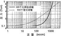
图3示出了当喷头采用孔眼型和优选管型喷嘴阵列设计时的喷嘴压力的计算值与化学试剂剂量调配流量之间关系的曲线图。Fig. 3 is a graph showing the relationship between the calculated value of the nozzle pressure and the chemical reagent dosage flow rate when the spray head adopts the design of perforated and preferably tubular nozzle arrays.
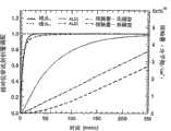
图4示出了以下两种情况下的喷头和沉积室的相对化学试剂剂量调配(用化学反应气体替换惰性清理气体)与化学试剂剂量调配时间之间关系的曲线图,即在化学试剂剂量阶段的起始时具有和没有增压室产生的化学试剂瞬态脉冲,图中显示出了增压室对化学试剂剂量调配效率的作用;Figure 4 shows a graph of relative chemical dosing (replacing an inert purge gas with a chemically reactive gas) versus chemical dosing time for the showerhead and deposition chamber for two cases, i.e. during the chemical dosing phase The chemical transient pulses with and without the pumping chamber at the start of , showing the effect of the pumping chamber on the chemical dosing efficiency;
图5示出了一个曲线图,图中比较了根据本发明的ALD的实施例中的实际的化学试剂使用与现有技术中的传统连续流动处理;Figure 5 shows a graph comparing actual chemical reagent usage in an embodiment of ALD according to the present invention with conventional continuous flow processing in the prior art;
图6以示意形式示出了通过根据本发明的SMFD型ALD系统的各种气流;Figure 6 shows in schematic form various air flows through the SMFD type ALD system according to the present invention;
图7以曲线图的形式示出了当Q3设定为1100sccm时Q1、Q2和Q4与时间之间的计算关系曲线(参看图6);Figure 7 shows in graph form the calculated relationship between Q1, Q2 and Q4 versus time when Q3 is set to 1100 sccm (see Figure 6);
图8示出了当(图6中的)Q3为1100sccm时沉积室压力、抽取控制室压力以及它们之间的压力差ΔP与时间之间的关系曲线;Fig. 8 shows the relationship curve between the deposition chamber pressure, the extraction control chamber pressure and the pressure difference ΔP between them and time when Q3 (in Fig. 6) is 1100 sccm;
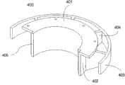
图9以示意形式示出了一种根据本发明的示例的化学试剂去除元件的设计;Figure 9 shows in schematic form a design of an exemplary chemical removal element according to the present invention;
图10示出了根据本发明的ALD系统的流路图,所述ALD系统在所述抽取控制室的下游包括一个单独的去除室;Figure 10 shows a flow diagram of an ALD system comprising a separate removal chamber downstream of the draw control chamber in accordance with the present invention;
图11示出了根据本发明的ALD系统的流路图,所述ALD系统包括一个主动压力控制室;Figure 11 shows a flow diagram of an ALD system according to the present invention, said ALD system including an active pressure control chamber;
图12以示意形式示出了一种根据本发明的包括一个DGIC的示例SMFD型ALD系统;Figure 12 shows in schematic form an exemplary SMFD-type ALD system including a DGIC according to the present invention;
图13示出了一种根据本发明使用的多端口气体导入阀;Figure 13 shows a multi-port gas introduction valve used in accordance with the present invention;
图14为一个三维图,示出了在使用根据本发明的SMFD型ALD装置和方法沉积出了Al2O3的200毫米的晶片基板上的薄膜厚度与晶片位置之间的关系;Fig. 14 is a three-dimensional diagram showing the relationship between film thickness and wafer position on a 200 mm wafer substrate of Al2 O3 deposited using the SMFD type ALD apparatus and method according to the present invention;
图15以示意形式示出了根据本发明的包含一个DGIC和一个PSV(处于关闭位置)的ALD反应器容器的优选实施例的剖视图;Figure 15 shows in schematic form a cross-sectional view of a preferred embodiment of an ALD reactor vessel comprising a DGIC and a PSV (in closed position) according to the present invention;
图16示出了图15中的所述反应器容器,其中PSV处于打开位置;以及Figure 16 shows the reactor vessel of Figure 15 with the PSV in an open position; and
图17以示意形式示出了一种被设计用于处理室中为非中心对称流动的根据本发明的SMFD系统。Figure 17 shows in schematic form an SMFD system according to the invention designed for a non-centrosymmetric flow in a process chamber.
具体实施方式Detailed ways
下面,参看图1-17描述本发明。为了清楚起见,在不同附图中使用相同的附图标记表示相似或相同的构件。应当理解,在图1-17中以示意形式示出的结构和系统起着说明目的,而不是对根据本发明的实际结构和系统的精确描述。而且,在此描述的实施例是示例性的,而不是用于限制本发明的范围,本发明的范围由权利要求书限定。下面,主要参照用于在单个200毫米的晶片基板上进行原子层沉积的系统和方法来描述根据本发明的实施例。可以理解,本发明可用于较大或较小尺寸的晶片基板,并且以下描述的尺寸和操作变量能够适当地增大或减小。Next, the present invention will be described with reference to FIGS. 1-17. For purposes of clarity, the use of the same reference numbers in different drawings indicates similar or identical components. It should be understood that the structures and systems shown in schematic form in FIGS. 1-17 are for purposes of illustration rather than precise descriptions of actual structures and systems in accordance with the present invention. Furthermore, the embodiments described herein are exemplary and not intended to limit the scope of the present invention, which is defined by the claims. In the following, embodiments according to the present invention are described primarily with reference to systems and methods for atomic layer deposition on a single 200 mm wafer substrate. It will be appreciated that the present invention can be used with larger or smaller sized wafer substrates, and that the dimensions and operating variables described below can be scaled up or down as appropriate.
原子层沉积(“ALD”)优选在以下条件下进行,即在清理过程中使用最大可能的通过沉积室的流量,在化学试剂的剂量调配过程中使用最小可能的流量。因此,高效的ALD系统能够产生和提供相当大的流量调节。在稳态情况下,处理气体(惰性清理气体或化学反应气体)进入沉积室的流量与处理气体排出沉积室的流量相匹配,其中,前者在此称为“流入流量”,后者在此称为“抽出流量”。Atomic layer deposition ("ALD") is preferably performed using the highest possible flow rate through the deposition chamber during cleaning and the smallest possible flow rate during chemical dosing. Therefore, an efficient ALD system is able to generate and provide considerable flow regulation. In steady state conditions, the flow rate of process gas (inert cleaning gas or chemical reaction gas) entering the deposition chamber matches the flow rate of process gas exiting the deposition chamber, where the former is referred to herein as "inflow flow" and the latter as For "extract flow".
为了提供相当大的流量调节,根据本发明的系统能够大致地匹配流入流量和抽出流量。例如,典型的ALD周期包含以下顺序步骤:气体流量分别为10sccm、1000sccm、5sccm和1000sccm的化学试剂A的剂量调配、化学试剂A清理、化学试剂B的剂量调配和化学试剂B清理。如果抽出流量可被控制成以大致相同的流量进行同步调节,处理压力就可保持大致稳定。In order to provide considerable flow regulation, the system according to the invention is able to roughly match the inflow and extraction flows. For example, a typical ALD cycle contains the following sequential steps: chemical A dosing, chemical A purge, chemical B dosing, and chemical B purge with gas flow rates of 10 sccm, 1000 sccm, 5 sccm, and 1000 sccm respectively. If the extraction flow rate can be controlled to be adjusted synchronously at approximately the same flow rate, the process pressure can be kept approximately constant.
当抽出流量调节不与流入流量调节大致匹配时,所述系统不能保持处理压力。实际上,所述系统会不可避免地瞬间变化到显著不同的压力,该压力可使流入流量和抽出流量匹配。When the drawdown flow adjustment does not approximately match the inflow flow adjustment, the system cannot maintain process pressure. In practice, the system will inevitably change momentarily to significantly different pressures, which can match the inflow and extraction flows.
进入沉积室或其他类型的处理室的流入流量通常使用上游支管进行控制,与处理压力大致无关。抽出流量通常由处理室出口的传导率CPC和出口两侧的压力差ΔP=PPG-PDraw决定。因此,抽出流量=CPCΔP。一般而言,抽出流量调节能够通过调节传导率CPC或压力差ΔP或调节两者来实现。在处理室之外调节传导率通常用于使用称为节流阀的机械装置的处理流系统例如CVD、PVD和蚀刻系统的技术领域中。尽管节流阀在上述系统中已经能够充分地用于控制稳态压力,但是它们普通太慢而不能提供SMFD系统中所要求的快速响应时间。此外,节流阀可引起不良的流动扰动和产生颗粒。为了消除流动扰动和颗粒产生问题,节流阀通常传统上在距处理区相当远的下游位置处使用。然而,一种优选的ALD系统设计通过强制使抽出流量控制器的位置接近基板而能使ALD沉积室的容积最小化。其他用于调节传导率的方法例如改变处理室出口的温度在范围上受到很大限制并且非常慢。最后,抽出流量调节可通过调节真空泵的抽气速率实现。然而,相当大的抽气速率调节响应缓慢,并且如果试图获得预期的切换速率还会显著地磨损泵。Inflow flow into a deposition chamber or other type of process chamber is typically controlled using an upstream branch and is approximately independent of process pressure. The draw flow rate is usually determined by the conductance CPC of the outlet of the processing chamber and the pressure difference ΔP=PPG -PDraw on both sides of the outlet. Therefore, extraction flow = CPC ΔP. In general, extraction flow regulation can be achieved by regulating conductance CPC or pressure differential ΔP or both. Regulation of conductance outside the process chamber is commonly used in the art of process flow systems such as CVD, PVD and etch systems using mechanical devices known as throttle valves. While throttle valves have been adequately used in the systems described above to control steady state pressure, they are generally too slow to provide the fast response times required in SMFD systems. Additionally, throttling valves can cause undesirable flow disturbances and particle generation. To eliminate flow turbulence and particle generation problems, throttle valves are usually traditionally used at a location quite far downstream from the treatment zone. However, a preferred ALD system design minimizes the volume of the ALD deposition chamber by forcing the location of the draw flow controller close to the substrate. Other methods for adjusting conductivity, such as changing the temperature of the process chamber outlet, are very limited in scope and very slow. Finally, the pumping flow adjustment can be realized by adjusting the pumping rate of the vacuum pump. However, sizable pumping rate adjustments are slow to respond and also wear the pump significantly if trying to achieve the desired switching rate.
因此,最适合于抽出流量调节的根据本发明的方法是ΔP调节。在将处理室压力PPC保持大致恒定的前提下的ΔP调节是通过根据本发明调节PDraw实施的。例如,抽取控制室(DC)位于处理室的下游,并且所述抽取控制室具有一个传导率为CDraw的出口。通过对气体进入和通过所述抽取控制室时的流动进行控制,PDraw能够在独立于上游的处理室或沉积室中的压力PPC的情况下得到控制。进入所述抽取控制室的气体流量是从所述处理室抽出的气体流量与直接介入的抽取气体流量之和。由于抽出流量是ΔP的函数,因此ΔP的独立控制可使抽出流量在独立于流入流量的情况下与流入流量匹配。由于原则上所述抽取控制室能够做得非常小,因此在某些实施例中的ΔP调节可以亚毫秒的速度执行。本发明的某些实施例能够有利地使用小容积DC室实施,以有利于实现具有非常短的瞬态时间的处理条件。其他实施例有利地牺牲抽取控制速度,以提供显著较大的抽取控制室。容积为几升的抽取控制室可用于捕获或去除化学试剂。这样,就会使典型的200毫米的晶片沉积系统中的抽取控制响应时间介于10毫秒-20毫秒的范围内,但可使其具有大约3升的可用抽取控制室空间所带来的利处。尽管这种“较慢的”抽取控制响应时间通常会使沉积室中的压力在化学试剂的剂量调配阶段的结束之际发生大约5%-15%的变化,但模拟和实际操作结果均表明这些压力变化对ALD性能的影响微乎其微。不可避免的处理压力变化与以下因素有关,即ALD室在大的清理流量开始时的通常较短(例如,2毫秒-4毫秒)的响应时间与所述抽取控制室的较长(例如,10毫秒-20毫秒)的响应时间之间存在差别。在某些实施例中,通过使用这样一种小抽取控制室(例如,40毫升),即在其下游设有一个单独的附加去除室,可同时提供快速响应抽取控制室和大容积去除室。在这种情况下,由于抽取控制室FRE上的压力下降可以优选很大,因此附加去除室中的停留时间可通过使用大容积去除室而被保持得足够长。例如,如果在抽取控制室FRE上压力下降了10倍,去除室就必须变大10倍,以提供相似的有效去除效果,这时去除室的容积通常要取10升-50升而不是1升-5升。这种尺寸对比说明了降低理想SMFD性能带来的益处,从而可认为在绝大部分情况下足以实现在抽取控制室中捕获或去除化学试剂。另外,当抽取控制室只用作抽取控制的目的(意思是说它们非常小)时,应当注意将ALD清理阶段延长到可清理抽取控制室,以保证在抽取控制室中不会生长出劣质膜。由于这些室能够做成具有30cc-70cc的容积来用于典型的200毫米的晶片系统,并且这些室由于大的抽出流量在化学试剂的剂量调配过程中能够显著地稀释化学试剂而还会承受非常小的局部的化学试剂压力,因此上述情况对产量的影响微乎其微(假如抽取控制室流路设计得非常合理并且抽取控制室壁被控制在合适的温度下)。Therefore, the method according to the invention most suitable for extraction flow regulation is ΔP regulation. The adjustment of ΔP under the premise of keeping the process chamber pressure PPC approximately constant is carried out by adjusting PDraw according to the invention. For example, a draw control chamber (DC) is located downstream of the process chamber and said draw control chamber has an outlet with a conductivity CDraw . By controlling the flow of gas into and through the draw control chamber, PDraw can be controlled independently of the pressure PPC in the upstream process or deposition chamber. The gas flow rate entering the extraction control chamber is the sum of the gas flow rate extracted from the process chamber and the directly intervening extraction gas flow rate. Since draw flow is a function of ΔP, independent control of ΔP allows draw flow to match inflow independently of inflow flow. Since in principle the draw control chamber can be made very small, in some embodiments the ΔP regulation can be performed at sub-millisecond speeds. Certain embodiments of the present invention can advantageously be implemented using a small volume DC chamber to facilitate processing conditions with very short transient times. Other embodiments advantageously sacrifice draw control speed to provide significantly larger draw control chambers. Extraction control chambers with volumes of several liters are used to capture or remove chemical reagents. This results in draw control response times in the range of 10 ms-20 ms in a typical 200mm wafer deposition system, but with the benefit of approximately 3 liters of draw control chamber space available . Although this "slower" draw control response time typically causes a change in pressure in the deposition chamber of the order of 5%-15% at the end of the chemical dosing phase, both simulations and real-world operating results indicate that these Pressure changes have negligible impact on ALD performance. The unavoidable process pressure variation is related to the typically short (e.g., 2 ms-4 ms) response time of the ALD chamber at the onset of a large purge flow versus the longer (e.g., 10 ms) response time of the draw control chamber. milliseconds - 20 milliseconds) response time difference. In certain embodiments, both a fast response draw control chamber and a large volume removal chamber can be provided by using a small draw control chamber (eg, 40 ml) downstream of which there is a single additional removal chamber. In this case, the residence time in the additional removal chamber can be kept sufficiently long by using a large-volume removal chamber, since the pressure drop over the extraction control chamber FRE can preferably be large. For example, if the pressure drop on the extraction control chamber FRE is 10 times larger, the removal chamber must be 10 times larger to provide similar effective removal, and the volume of the removal chamber is usually 10-50 liters instead of 1 liter -5 liters. This size comparison illustrates the benefits of reducing the performance of the ideal SMFD, which can be considered sufficient in most cases to achieve capture or removal of chemical agents in the draw control chamber. Also, when the draw control chambers are used only for draw control purposes (meaning they are very small), care should be taken to extend the ALD cleaning phase to clean the draw control chambers to ensure that no bad film grows in the draw control chambers . Since these chambers can be made to have a volume of 30cc-70cc for a typical 200mm wafer system, and the chambers are also subject to extreme pressure due to the large draw flow which can significantly dilute the chemicals during dosing of the chemicals. Small local chemical reagent pressure, so the above situation has negligible impact on throughput (provided that the extraction control chamber flow path is well designed and the extraction control chamber wall is controlled at an appropriate temperature).
ΔP调节的响应时间与PDC调节的响应时间直接相关,并且取决于DC容积、DC出口的传导率和流入流量。The response time of the ΔP regulation is directly related to the response time of thePDC regulation and depends on the DC volume, the conductance of the DC outlet and the inflow flow.
图1示出了根据本发明的同步调节流入流量抽出流量(“SMFD”)的ALD系统100的基本实施例的流路图。FIG. 1 shows a flow diagram of a basic embodiment of a Synchronously Modulated Inflow Drawdown ("SMFD")
ALD系统100包括一个压力稳定的惰性清理气体源101。清理气体通过清理源截止阀102和清理源节流元件(“FRE”)103供给气体分配室104,所述气体分配室104通常为一个传统喷头。如图1所示,清理源截止阀102和清理源FRE 103在清理气体源101与气体分配室104之间提供了连续流体连通。在这里,节流元件(FRE)可在气体流经它们时使气体压力降低。一种化学反应物前体在多个化学气体源105、105’处被以良好控制的压力提供,所述化学反应物前体采用下述形式:纯化学气体,源于液体或固体化学试剂的蒸气,或者蒸气或气体化学试剂与惰性气体的混合物。化学气体源105通过化学试剂源FRE 106以流体连通的方式串联着增压室107。增压室107通过化学试剂剂量调配截止阀110和增压室FRE 109以流体连通的方式串联着气体分配室(喷头)104。气体分配室104通过增压室FRE 109、清理排气截止阀108和清理排气FRE 111以流体连通的方式串联着清理排气管112。如图1所示,化学试剂剂量调配截止阀110和清理排气截止阀108在系统100的气体支管系统的并联支路中均包括一个普通的二通阀,所述并联支路从接点123分叉。
如图1所示,第二化学气体源105’通过使用与参照化学气体源105描述的装置相同的装置与喷头104和清理排气管112连接。As shown in FIG. 1, a second chemical gas source 105' is connected to the
气体分配FRE 113在气体分配室104与原子层沉积室(“沉积室”)114之间提供连续流体连通。在气体分配室104是一个喷头装置的优选实施例中,气体分配FRE 113通常为喷嘴阵列113。喷嘴阵列用于从气体分配室104向沉积室114提供限制的和均匀的流动,其中,所述沉积室114含有一个正被处理的基板。沉积室114通过沉积室FRE 115以流体连通的方式串联着抽取控制室116。抽取控制室116包括一个抽取控制出口124,其通过抽取控制FRE 117和真空管118以流体连通的方式串联着真空泵125。抽取气体源101通过抽取气体管119、抽取源截止阀120和抽取源FRE 121以流体连通的方式串联着抽取控制室116。
在典型的ALD操作过程中,系统100基本上是在两种静态模式即一种清理模式和一种化学试剂剂量调配模式之间进行切换的。ALD操作的两种基本模式的代表性的阀设置如表1所示。During typical ALD operation, the
表1Table 1
为了清楚起见,以稳定压力处理的情况来描述用于操作SMFD系统的方法。如前部分所述,这种模式通常可在关键应用场合中产生很好的结果。而且,如上所述,可以理解,ALD处理通常包括一个具有至少四个不同阶段的周期,所述周期顺次重复执行多次,以沉积出预期的薄膜。参看表1和图1描述的上述两种模式是典型的四阶段周期中的化学试剂剂量调配阶段和清理阶段的代表。在清理模式中,在清理气体源101的已知清理源压力下,FRE103和113被设计用于从清理气体源101向气体分配室104输送预期流量Qpurge的清理气体;然后清理气体通过气体分配室104、沉积室114和抽取控制室116进入抽取控制出口124;随后在喷头压力PpurgeSH和ALD沉积室压力P114保持不变的情况下通过FRE 109和清理排气截止阀108到达清理排气管112。在化学试剂剂量调配模式中,在化学气体源105的已知压力下,FRE 106和109被设计成将化学反应气体通常以化学试剂剂量调配流量QCD输送到气体分配室(喷头)104,其中,QCD优选显著小于Qpurge。这种较低流量同时还伴随着较低的喷头压力PCDSH。由于沉积室114和气体分配室104中对应的压力P114、P104(通常以mTorr的单位测量)均显著地低于化学气体源105的压力(通常以Torr的单位测量),因此FRE 106、109通常被设计成这样,即化学试剂剂量调配流量QCD实际上与压力P114和P104独立。在化学试剂剂量调配模式中,在已知抽取气体源压力下的抽取气体源101通过FRE 121将抽取气体以预期的抽取气体流量供给抽取控制室116。根据本发明,抽取气体源101的抽取气体源压力和FRE 121决定了通过抽取控制室116的抽取气体流量。这种抽取气体流量和FRE 117在抽取控制室116中建立了化学试剂剂量调配抽取压力。所述抽取压力随着抽取气体流量增加而增加。沉积室114与抽取控制室116之间的压力差以及FRE 115的传导率共同决定从沉积室114排出的处理气体的抽出流量,所述处理气体包括未反应的化学试剂前体。从沉积室114进入并通过抽取控制室116的处理气体的抽出流量还会稍微地增大通过抽取控制室116的气体总流量,因此会增大抽取压力。抽取控制室116中的化学试剂剂量调配的抽取压力的增大会降低从沉积室114进入并通过抽取控制室116的抽出流量。相反,抽取控制室116中的化学试剂剂量调配的抽取压力的降低会增大从沉积室114进入并通过抽取控制室116的抽出流量。For clarity, the method for operating the SMFD system is described in the context of a steady pressure process. As mentioned in the previous section, this mode usually yields good results in critical applications. Also, as noted above, it will be appreciated that an ALD process typically includes a cycle of at least four distinct stages that is repeated multiple times in sequence to deposit a desired film. The above two modes described with reference to Table 1 and Figure 1 are representative of the chemical dosing and cleaning phases of a typical four-phase cycle. In purge mode, at the known purge source pressure of
在根据本发明的优选实施例中,除了所述两种静态模式即清理模式和稳态化学试剂剂量调配模式以外,还在化学试剂剂量调配的起始动作中设计了一种重要的瞬态(过渡)模式。起始瞬态流量由来自增压室107的化学气体流产生。在截止阀110关闭后的指定时间内可达到平衡,增压室107中的压力等于化学气体源105的压力,即当截止阀110打开时,在稳态条件下,增压室107中的稳态压力P107SS由于FRE 106上的压力梯度而会小于P105。当截止阀110被致动打开时,增压室107中的起始压力从P105瞬间降低到稳态压力P107SS。化学反应气体在化学试剂剂量调配的过程中进入气体分配室104的流入流量由增压室107的压力和FRE109的传导率决定。增压室107的压力瞬变可引起气体分配室104的压力瞬变。这样,在增压室107的压力瞬变过程中,化学反应气体进入沉积室114的相应的流入流量为逐渐降至稳态流量的起始脉冲式流量。同时,抽取控制室116中的抽取压力为瞬间下降的起始脉冲式压力。瞬态时间由抽取控制室116的容积、抽出流量和FRE 117的传导率共同决定。在抽取控制室116的压力瞬变过程中,沉积室114的抽出流量也会跟随着发生下降瞬变。通过对FRE 106、109和117中的每个FRE、抽取控制流量以及增压室107和抽取控制室116的容积进行选择性设计,使瞬态流入流量和瞬态抽出流量相互匹配,以使沉积室114中的压力偏移最小化。然而,本发明的一个重要方面是,即使在瞬态时间常数不能很好地匹配并且各个不同阀的动作不能很好地同步的情况下也可通过SMFD系统(特别是在稳定压力下操作时)固有地抑制压力偏移。事实上,本发明的一些实施例中所讲述的使用SMFD的主要优点是能够在非常便利和低成本的情况下使性能对装置和处理过程的缺陷不敏感。In a preferred embodiment according to the present invention, in addition to the two static modes, i.e. the cleaning mode and the steady-state chemical reagent dosage dispensing mode, an important transient state ( transition) mode. The initial transient flow is generated by the chemical gas flow from the
优选地,剂量调配步骤被设计用于使化学试剂流量最大化和使化学试剂的使用量最小化。例如一个极端实例,一种用于处理200毫米的晶片的典型的300cc-400cc的ALD室在200mTorr的化学试剂剂量调配压力下实际上不会损耗化学试剂。因此,在200mTorr的压力下执行100%的化学试剂剂量调配除了增压室的作用以外通常只需要非常小的另外的化学试剂剂量调配流量。实际上,我们已发现,在200mTorr的压力下执行未稀释前体的剂量调配的条件下,除了用于在300℃下进行Al2O3的ALD的三甲基铝(“TMA”)的增压室剂量调配以外的另外的剂量调配的影响作用小于2%。因此,使用典型的小于10sccm的TMA稳态流量足以实现最优化的ALD性能。Preferably, the dosing step is designed to maximize chemical flow and minimize chemical usage. As an extreme example, a typical 300cc-400cc ALD chamber for processing 200 mm wafers would have virtually no chemical consumption at a chemical dosing pressure of 200 mTorr. Therefore, performing 100% chemical dosing at a pressure of 200 mTorr typically requires very little additional chemical dosing flow beyond the action of the pumping chamber. Indeed, we have found that under conditions where dosing of the undiluted precursor is performed at a pressure of 200 mTorr, the addition of trimethylaluminum (“TMA”) for ALD of Al2 O3 at 300° C. The effect of additional dosing beyond the chamber dosing was less than 2%. Therefore, using a typical TMA steady-state flow rate of less than 10 sccm is sufficient to achieve optimal ALD performance.
在化学试剂剂量调配阶段中的稳态流量通常是清理阶段中的清理气体流量的1/10-1/100。因此,用于建立化学试剂剂量调配的稳态的时间会长得不可接受。为了避免上述情况对产量的不良影响,根据本发明的实施例的有效化学试剂剂量调配步骤可用于在化学试剂剂量调配步骤的起始阶段提供起始非常大的化学试剂流量。因此,起始流量的瞬变可显著地降低化学试剂剂量调配阶段的响应时间。这种响应时间的降低对于提高ALD处理的效率和产量非常重要。在化学试剂剂量调配阶段的起始瞬态部分中,气体分配室104和沉积室114的容积会被处于起始高压力和相应的起始高瞬态流量下的化学气体脉冲很快地充满。在化学试剂剂量调配过程中的起始瞬态流量通常被调节成与之前的清理阶段中的惰性清理气体流的清理流量匹配。因此,可保持流动的连续性。由于化学气体在起始高的化学试剂剂量调配流量的作用下流过气体分配室104和沉积室114时的停留时间非常短,因此气体分配室104和沉积室114会很快地充满化学气体。增压室容积和增压室FRE被选择性设计成在化学试剂剂量调配的起始阶段与抽取控制室的压力的增加大致匹配。增压室容积还被设计成可提供大小为ALD室在剂量调配过程中的容积与压力乘积的1-2倍的增压室总接触量。例如,如果沉积室容积为400cc和剂量调配压力为200mTorr,则增压室容积被设计成可提供0.08L×Torr-0.16L×Torr的增压室总接触量。当ALD系统100从化学试剂剂量调配模式切换到清理模式时,瞬变通常会较不重要。气体分配室104的相对较小的容积再加上FRE 103的相对较大的传导率可使气体分配室104的压力快速地达到PpurgeSH。当使用小容积的抽取控制室时,抽取控制室116中的压力从化学试剂剂量调配抽取压力降至清理抽取压力的时间远小于清理停留时间,并且从剂量调配切换到清理的操作需要几毫秒的时间。然而,当抽取控制室的容积较大时,抽取控制室的压力下降的响应时间比处理室中的清理停留时间长。例如,在用于200毫米的晶片上的ALD的典型处理中,处理室中的气体停留时间为3毫秒。在化学试剂剂量调配与清理之间的抽取压力调节范围为总抽取压力的10%-20%。通常,容积为1升-5升的抽取控制室便于将去除能力集成到所述系统中(见以下描述)。因此,抽取控制室压力调节之后紧跟着长为10毫秒-20毫秒的典型时间。这样,在剂量调配步骤结束时处理室的一些压力偏移就不可避免。然而,这些压力调节不会导致对可测量性能的损害。而且,在例如化学试剂剂量调配阶段的起始脉冲的情况下不会有意地产生瞬变。因此,与终止化学试剂剂量调配阶段相关的瞬变影响较小。The steady state flow in the chemical dosing phase is typically 1/10-1/100 of the purge gas flow in the purge phase. Consequently, the time to establish a steady state for chemical dosing can be unacceptably long. In order to avoid the adverse impact of the above situation on the yield, the effective chemical reagent dosage preparation step according to the embodiment of the present invention can be used to provide an initial very large chemical reagent flow rate in the initial stage of the chemical reagent dosage preparation step. Thus, a transient in the initial flow can significantly reduce the response time of the chemical dosing phase. This reduction in response time is very important for improving the efficiency and throughput of ALD processing. During the initial transient portion of the chemical dosing phase, the volumes of the
如上所述,根据本发明的SMFD型ALD系统可解决在清理过程中对高流量(和低压力)的要求(以便能够实现高效率和短时间清理)与在化学试剂剂量调配过程中对低流量(和高压力)的要求(以便能够实现快速反应和高化学试剂利用率)之间的传统协调问题。在稳定压力的实施例中,所述系统能够保持大致恒定的处理压力,同时又可使流量的调节幅度超过10倍。事实上,根据本发明的处理硬件和方法已经成功地用于在稳定压力下产生调节幅度超过100倍的流入流量和抽出流量调节。作为一种替代性方法,压力和流量均能够得到调节,以使清理阶段和化学试剂剂量调配阶段具有甚至更高的效率而且实际上不需要进行任何折衷协调。根据本发明的装置和方法通过同步地调节(气体排出沉积室的)抽出流量和气体进入沉积室的流入流量实现了上述预期能力。As mentioned above, the SMFD type ALD system according to the present invention can solve the requirement of high flow (and low pressure) during the cleaning process (so as to achieve high efficiency and short cleaning time) and the requirement of low flow during the chemical reagent dosage process. (and high pressure) requirements to enable fast reactions and high chemical reagent utilization). In a steady pressure embodiment, the system is capable of maintaining a substantially constant process pressure while allowing the flow rate to be adjusted by a factor of more than 10. In fact, processing hardware and methods in accordance with the present invention have been successfully used to produce inflow and extraction flow modulations of over 100 times modulation at steady pressure. As an alternative, both pressure and flow can be adjusted to make the purge and chemical dosing phases even more efficient without practically any compromises. The apparatus and method according to the present invention achieve the aforementioned desired capabilities by simultaneously adjusting the extraction flow (of gas out of the deposition chamber) and the inflow of gas into the deposition chamber.
根据本发明的系统和方法的一个优点是用于实施本发明的一些结构和技术可通过新颖组合的方式使用商品部件,从而可使本发明的实施例能够低成本地设计和使用。例如,某些实施例包含一个处于已知压力下的惰性气体的集中单个供给点,其气体在所述系统内以可选择性控制的方式分配通过节流元件。惰性气体源的一个实例是市场上可获得的压力控制器(例如,MKS 640A系列)和气体容器。另一个实例是普通的压力调节器。在根据本发明的某些实施例中,大约100毫秒的持续时间是化学试剂剂量调配阶段和清理阶段中的每个阶段的实际目标。相应系统的气体动力学通常是以系统响应时间小于5毫秒的目标设计的。因此,为了避免在阀102、120、108和110之间以及与其他化学试剂源相关的阀中产生不理想的瞬态条件、压力不稳定和波动(不可控制和不可重复的延迟),优选使用能够以小于5毫秒的速度启动的阀。阀108和110是用于一个化学试剂源的一组阀。在图1中所示的特殊实施例中,所述ALD系统包括两组这样的阀,分别用于每个化学试剂源。ALD系统通常需要至少两个不同的化学气体源。5毫秒和更快的启动速度比UHP隔膜阀的典型启动速度快。然而,几种商业产品可实现这样的启动速度,所述商业产品包括:UHP电磁阀(例如,Parker General Valve系列99,Fujikin ECV系列)、压电阀、电子燃料喷射器、比例阀和快速MFC(例如,Mach One ofAE-EMCO)。One advantage of the systems and methods according to the invention is that some of the structures and techniques used to implement the invention can use commodity components in novel combinations, thereby enabling embodiments of the invention to be inexpensively designed and used. For example, certain embodiments include a centralized single supply point of inert gas at a known pressure that is distributed within the system in a selectively controllable manner through a throttling element. An example of a source of inert gas is commercially available pressure controllers (eg, MKS 640A series) and gas containers. Another example is a common pressure regulator. In some embodiments according to the invention, a duration of approximately 100 milliseconds is a practical target for each of the chemical dosing phase and the cleaning phase. The gas dynamics of the corresponding systems are usually designed with the goal of a system response time of less than 5 milliseconds. Therefore, to avoid undesirable transient conditions, pressure instability and fluctuations (uncontrollable and non-repeatable delays) between
根据本发明的实施例使用了FRE。例如,FRE可以是可调节构件(例如,计量阀、比例阀、热节流孔和快速MFC)或被动构件(节流孔、导流体、毛细管和多孔介质)。被动FRE通常比可调节FRE便宜和坚固。然而,可调节FRE通常更适合于进行最优化调节。在气体流路上的未包含截止阀的部分中,所要求的FRE传导率优选被设计为所述流路的传导率。在气体流路上的包含截止阀和FRE的部分中,优选这样设计,即将所述FRE与所述截止阀结合成一体。在结合成一体的阀-FRE中,优选将所述截止阀设计成在其完全打开时可具有必需的传导率。作为一种替代性的方法,例如比例阀和一个马赫数的快速MFC的装置能够打开到具有预期的传导率。在根据本发明的系统和方法的最优化中,FRE 103、106、109、111和121的调节能力可使静态清理模式、静态化学试剂剂量调配模式和化学试剂剂量调配瞬态性能得到高效和独立地最优化。Embodiments according to the invention use FRE. For example, FREs can be adjustable components (eg, metering valves, proportional valves, thermal orifices, and fast MFCs) or passive components (orifices, flow guides, capillaries, and porous media). Passive FREs are generally less expensive and stronger than adjustable FREs. However, an adjustable FRE is usually better suited for optimal tuning. In the portion of the gas flow path that does not contain a shut-off valve, the required FRE conductance is preferably designed as the conductance of the flow path. In the portion of the gas flow path that includes the shutoff valve and the FRE, it is preferable to design such that the FRE is integrated with the shutoff valve. In an integrated valve-FRE, the shut-off valve is preferably designed to have the necessary conductance when it is fully open. As an alternative, devices such as proportional valves and a Mach number fast MFC can be opened to have the desired conductance. In optimization of the systems and methods according to the present invention, the tuning capabilities of
化学气体源105的压力优选大于1Torr,以便高到足以方便使用。此外,化学气体源105必须能够在化学试剂剂量调配阶段的过程中保持压力不变。The pressure of the
术语“室”和相关术语是指一种具有相对大致封闭的容积V且设有至少一个入口和一个出口的构件,其中,在可用流量Q的范围内,通过所述室(例如,在入口与出口之间)的压力梯度ΔP显著小于所述室中的平均压力P。一般而言,在根据本发明的实施例中,当V大约为1000cc和通过室的流量Q大约为1000sccm或更小时,室的比值ΔP/P小于0.1。而且,在这里,气体在室内的停留时间相当大,所述停留时间由τ=VP/Q定义。一般而言,在这里,气体在室中的停留时间τ通常为50微秒或更长。The term "chamber" and related terms refer to a member having a relatively substantially closed volume V and provided with at least one inlet and one outlet, wherein, within the range of available flow Q, through the chamber (for example, between the inlet and The pressure gradient ΔP between the outlets) is significantly smaller than the average pressure P in the chamber. In general, when V is about 1000 cc and the flow rate Q through the chamber is about 1000 sccm or less, the ratio AP/P of the chamber is less than 0.1 in embodiments according to the invention. Also, here, the residence time of the gas in the chamber, defined by τ=VP/Q, is considerable. In general, here, the residence time τ of the gas in the chamber is typically 50 microseconds or more.
另一方面,术语“节流元件”(“FRE”)是指一种具有非常小的容积且通常仅具有一个入口和一个出口的构件,其中,在可用流量Q的范围内,压力梯度ΔP与FRE的所述入口和所述出口之间的平均压力P相比相对较大。一般而言,在这种规格的FRE中,当通过FRE的流量Q大约为1000sccm或更小时,比值ΔP/P大于0.1。而且,在这里,气体在FRE中的停留时间τ相对较短,通常小于50微秒。On the other hand, the term "throttling element" ("FRE") refers to a member with a very small volume and usually only one inlet and one outlet, in which, over the range of available flow Q, the pressure gradient ΔP and The average pressure P between the inlet and the outlet of the FRE is relatively large. Generally, in FREs of this size, the ratio ΔP/P is greater than 0.1 when the flow rate Q through the FRE is about 1000 sccm or less. Also, here, the residence time τ of the gas in the FRE is relatively short, typically less than 50 microseconds.
与具有基本无源元件例如电阻器、电容器和感应器的电路非常相似,压力梯度ΔP=0(非FRE特性)的室和V=0的FRE实际中并不存在。然而,与电路规则相似,含有室和FRE的ALD和其他流体流网络实际上能够通过使基本元件具有纯粹元件特性得到说明和设计。Much like a circuit with basic passive elements such as resistors, capacitors and inductors, chambers with pressure gradient ΔP=0 (non-FRE characteristic) and FREs with V=0 do not exist in practice. However, similar to electrical circuit rules, ALD and other fluid flow networks containing chambers and FREs can actually be specified and designed by making basic elements have purely elemental properties.
因此,本领域的技术人员可以理解使用了室和FRE的理想化特性的流动系统的描述和设计。例如,术语“处理室”意味着在处理空间中压力梯度通常被最小化,尽管清楚地知道在流动系统中只要存在流动就会存在压力梯度。事实上,在根据本发明的SMFD的某些实施例中,设计了一个加长的处理室,所述处理室的两侧之间具有压力梯度。Thus, description and design of flow systems using idealized properties of chambers and FREs can be understood by those skilled in the art. For example, the term "processing chamber" implies that pressure gradients are generally minimized in the processing volume, although it is well understood that pressure gradients will exist in a flow system as long as there is flow. In fact, in some embodiments of the SMFD according to the invention, an elongated process chamber is designed with a pressure gradient between its two sides.
FRE通常被设计和理想化成具有零或最小的容积,尽管对本领域的技术人员来说实际中根本无法实现V=0的FRE。也可以理解,如果不是特别规定,处理就可非常有利地在ΔP非常小的室中进行。另一方面,在某些情况下,具有非常小的V的(或τ)的FRE是不切实际的。然而,使用具有相当大的容积的FRE通常并不会对性能造成损害。具有相当大的容积的FRE的特性实际上是通过组合一个纯室V和一个纯FRE进行描述和设计的,这一点与对通过“等效电路”描述的电路元件例如具有电阻的感应器的电描述十分相似。FREs are usually designed and idealized to have zero or minimal volume, although FREs with V=0 are simply not practically achievable to those skilled in the art. It will also be appreciated that, if not otherwise specified, the process is very advantageously carried out in a chamber with a very small ΔP. On the other hand, FRE with very small V (or τ) is impractical in some cases. However, there is usually no performance penalty for using an FRE with a relatively large volume. The behavior of an FRE with a rather large volume is actually described and designed by combining a pure chamber V and a pure FRE, in the same way as for a circuit element described by an "equivalent circuit", such as an inductor with a resistance. The descriptions are very similar.
FRE的容积可通过增加与其最近的室的“有效”容积而被包含在设计中。室的节流特性能够通过将该室的残留传导率加在下游FRE的传导率上以获得“有效FRE”传导率Ceff而得以实现,其中The volume of the FRE can be included in the design by increasing the "effective" volume of the chamber closest to it. The restrictive properties of a chamber can be achieved by adding the residual conductance of the chamber to the conductance of the downstream FRE to obtain the "effective FRE" conductance Ceff , where
实际具有几个处于串联和并联的FRE的系统可用有效FRE表示,以便于对系统进行描述。例如,含有均为FRE的毛细管和阀的管可用单个有效FRE表示。在根据本发明的优选实施例中,流阻特性可被设计包含在阀的结构中。A system that actually has several FREs in series and parallel can be represented by an effective FRE to facilitate the description of the system. For example, a tube containing capillaries and valves that are both FREs can be represented by a single effective FRE. In a preferred embodiment according to the present invention, the flow resistance characteristic can be designed to be included in the structure of the valve.
图2以示意形式示出了根据本发明的SMFD型ALD反应器容器200的剖视图。为了清楚起见,装置200中的在现有技术中为标准形式的几个构件没有包含在图2中,这些构件例如有晶片装载端口、晶片升降销和电馈入结构。Fig. 2 shows in schematic form a cross-sectional view of a SMFD type
气体分配室(喷头)201具有100毫米的内径,其内部空间为3毫米高。所述喷头不必覆盖着所有晶片基板表面区域。因此,所述喷头的容积为23.6cm3。喷嘴阵列(FRE)202将气体分配室201的底部与沉积室203分隔开。一个200毫米的半导体晶片204位于热基板保持器205上,所述热基板保持器205由热传导金属(例如,W、Mo、Al和Ni)或现有技术中通常用于热基座和卡盘的其他材料制成。所述热基板保持器的周边通过良好的热触点(或作为一个部件加工)连接在FRE 206上。FRE 206被成形为一系列的径向狭槽。图2的右侧示出了没有狭槽的横截面的部分207。在操作过程中,气体通过沉积室FRE 206从沉积室203流入抽取控制室208中。气体通过可控制抽取的FRE 209从抽取控制室208流到真空端口210。抽取气体通过抽取气体管211、抽取源截止阀212和抽取源FRE 213进入抽取控制室208中,以控制抽取控制室208中的抽取压力。在典型的ALD操作过程中,抽取气体进入抽取控制室208的流量可被选择性地控制,以在不同阶段实现不同的压力,即在第一化学试剂剂量调配阶段的过程中实现第一剂量调配抽取压力,在清理阶段的过程中实现清理抽取压力,在第二化学试剂剂量调配阶段的过程中实现第二剂量调配抽取压力。正常地,相对于清理阶段过程中的流量,抽取气体进入抽取控制室208的流量在化学试剂剂量调配阶段的过程中增大,以增加抽取控制室208中的压力(剂量调配抽取压力),从而可降低处理气体(包含化学反应物前体)排出沉积室203的抽出流量,进而可使化学试剂的浪费最小化,并且如果需要可增大沉积室203中的化学试剂的压力和流量。在清理阶段中,抽取气体进入抽取控制室208的流量通常会降回到较低流量,以降低抽取控制室208中的压力(清理抽取压力),从而可增大清理气体排出沉积室203的抽出流量,以提供更高的清理气体流量和如果需要提供较低的清理压力。图2中还示出了化学试剂源管214、化学试剂源FRE 215、增压室216、化学试剂剂量调配截止阀217、清理排气截止阀218和增压室FRE 219。图中还示出了热障220,其被构造用于防止反应器容器壁221与反应器容器顶部222之间发生热传导。所述热障在以下实施例中非常有用,即其中反应器容器壁221与喷头(气体分配室)201在不同的可控温度下操作。The gas distribution chamber (shower head) 201 has an inner diameter of 100 mm, and its inner space is 3 mm high. The showerhead does not necessarily cover all of the wafer substrate surface area. Therefore, the volume of the spray head is 23.6 cm3 . A nozzle array (FRE) 202 separates the bottom of the
化学试剂的利用率和化学试剂的去除速度随着沉积室203的容积的降低而提高。各种技术中所使用的基板尺寸,例如通常用于半导体装置制作中的200毫米和300毫米的圆形硅晶片,决定了沉积室的尺寸。例如,用于处理一个200毫米的圆形晶片的沉积室必须具有直径至少为200毫米的圆形区域。气体流动动力学要求所述沉积室的高度应具有几毫米。因此,这种200毫米的沉积室的容积通常为至少150cm3,更通常为300cm3或更大。通常预期的~0.6秒的周期时间将化学试剂去除清理阶段的最大许可时间限制在大约0.1秒至0.2秒的范围内。在所述时间内,通常希望沉积室中的化学试剂前体反应物的浓度降至其初始值的1%以下。更精确地讲,化学试剂的去除程度由化学试剂的具体化学性质和对沉积膜质量的具体要求确定。在ALD周期的清理阶段的过程中,沉积室中的化学试剂的浓度与exp(-t/τ)成正比,其中,t是化学试剂的去除时间。因此,为了达到小于1%的程度,t需要等于或长于4.6τ。为了使4.6τ<0.2秒,VP/Q的值大约为0.044秒。如果V被通常限制在大于大约300cm3的范围内,P/Q就会限制在小于0.145sec/L的范围内。例如,如果Q为500sccm(6.33L×Torr/sec),则处理压力应等于或小于0.92Torr。作为另一个实例,如果需要将化学试剂的去除程度降至0.0001%,则沉积室在清理过程中的压力应限制在低于300mTorr的范围内。The utilization rate of the chemical reagents and the removal rate of the chemical reagents increase as the volume of the
在根据本发明的一个代表性实施例中,所述喷头(气体分配室)具有VSH=23.6cm3的容积。喷头压力为ALD空间的容积大约为400cm3。处理沉积室的稳定压力为P114=100mTorr。在清理阶段中清理气体通过所述喷头进入所述沉积室的流入流量被控制为Qpurge=1000sccm。从而,在清理阶段中,气体在所述喷头和所述沉积室中的停留时间τ=VP/Q分别为1毫秒和3毫秒。所述ALD系统和处理操作被设计成在400毫秒-500毫秒的周期时间下实施ALD。每个周期通常包括第一化学试剂剂量调配阶段、紧接在第一化学试剂剂量调配阶段之后的清理阶段、随后的第二化学试剂剂量调配阶段以及紧接在第二化学试剂剂量调配阶段之后的另一清理阶段。从而,每个阶段的目标持续时间为大约100毫秒。如果使用这些示例设计尺寸和操作条件,在清理阶段中,所述示例ALD系统可提供100次的喷头容积吹扫和多于30次的沉积室容积吹扫。所述容积吹扫次数远远大于使用传统的ALD技术通常能够达到的吹扫次数(例如,在1秒-5秒的清理时间内通常仅能进行3次-10次的沉积室容积吹扫)。SMFD装置和方法在以下方面优于传统的ALD方法和装置,即SMFD装置和方法的清理性能得到了显著地改进,清理时间得到了降低,并且化学试剂的利用率得到了提高。因此,在清理阶段中的喷头传导率可计算和设计为在根据本发明的SMFD型ALD系统的优选设计中,喷头流量对喷头压力具有高的灵敏度。因此,喷嘴阵列FRE中的喷嘴被设计成具有实际中尽可能大的长宽比。例如,在直径为100毫米的喷嘴阵列板上设有600个喷嘴的密集模式中,每个喷嘴在清理阶段中的气体流量大约1.67sccm。在厚度为3.125毫米(1/8英寸)的喷嘴阵列板中,管型喷嘴具有大约3毫米的长度。喷嘴直径的估计值可使用以下Poiseuille公式进行计算,即公式(1):In a representative embodiment according to the present invention, said showerhead (gas distribution chamber) has a volume of VSH =23.6 cm3 . Nozzle pressure is The volume of the ALD space is approximately 400 cm3 . The steady pressure of the process deposition chamber was P114 =100 mTorr. The inflow rate of purge gas through the showerhead into the deposition chamber during the purge phase was controlled to beQpurge = 1000 sccm. Thus, during the purge phase, the gas residence times τ=VP/Q in the showerhead and in the deposition chamber are 1 millisecond and 3 milliseconds, respectively. The ALD system and process operations are designed to perform ALD at a cycle time of 400 milliseconds to 500 milliseconds. Each cycle typically includes a first chemical dosing phase, a cleanup phase immediately following the first chemical dosing phase, a subsequent second chemical dosing phase, and a Another cleanup phase. Thus, the target duration of each phase is approximately 100 milliseconds. Using these example design dimensions and operating conditions, the example ALD system can provide 100 showerhead volume purges and more than 30 deposition chamber volume purges during the purge phase. The number of volumetric purges is much greater than is typically achievable using conventional ALD techniques (e.g., typically only 3-10 deposition chamber volumetric purges can be performed within a cleaning time of 1 second to 5 seconds) . The SMFD apparatus and method are superior to conventional ALD methods and apparatus in that the cleaning performance of the SMFD apparatus and method is significantly improved, cleaning time is reduced, and chemical utilization is increased. Therefore, the nozzle conductance during the cleaning phase can be calculated and designed as In a preferred design of the SMFD type ALD system according to the invention, the nozzle flow has a high sensitivity to the nozzle pressure. Therefore, the nozzles in the nozzle array FRE are designed to have as large an aspect ratio as practical. For example, in a dense pattern of 600 nozzles on a 100 mm diameter nozzle array plate, the gas flow rate per nozzle during the cleaning phase is about 1.67 sccm. In a nozzle array plate having a thickness of 3.125 mm (1/8 inch), the tubular nozzles have a length of approximately 3 mm. An estimate of the nozzle diameter can be calculated using the following Poiseuille formula, Equation (1):
其中,清理气体的粘度被理想化为250℃下N2的粘度,即η=270μpoise。相应的气体流量可由公式(2)计算:Among them, the viscosity of the cleaning gas is idealized as the viscosity ofN2 at 250°C, that is, η=270μpoise. The corresponding gas flow rate can be calculated by formula (2):
作为比较,可以考虑使用这样一种根据典型的喷头设计的喷头设计,即在直径为100毫米的喷嘴阵列板中设有300个孔眼型喷嘴,所述喷嘴具有非常小的孔眼长度。每个喷嘴的传导率(C=Q/ΔP)为105.6cm3/sec。喷嘴的面积可由公式(3)计算:As a comparison, a nozzle design according to a typical nozzle design in which 300 orifice-type nozzles are provided in a nozzle array plate having a diameter of 100 mm and having a very small aperture length can be considered. The conductance (C=Q/ΔP) of each nozzle was 105.6 cm3 /sec. The area of the nozzle can be calculated by formula (3):
其中,PSHpurge和P114分别为喷头压力和沉积室压力(Torr),γ=CV/CP为气体热容比,对于250℃下的N2来说该热容比为大约1.4。T1是喷头温度(假定该温度也是气体温度),其取250℃=523°K。M是气体的分子量(理想化为)。如果使用这些变量的值,通过公式(3)计算的喷头喷嘴的面积大约为A=4.4×10-3cm2。因此,喷嘴直径为大约750μm。清理气体流量由下面公式(4)计算:where PSHpurge and P114 are showerhead pressure and deposition chamber pressure (Torr), respectively, and γ = CV /CP is the gas heat capacity ratio, which is about1.4 for N at 250°C. T1 is the shower head temperature (assuming that this temperature is also the gas temperature), which is taken as 250°C=523°K. M is the molecular weight of the gas (ideally ). If the values of these variables are used, the area of the showerhead nozzle calculated by formula (3) is approximately A=4.4×10⁻³ cm2 . Therefore, the nozzle diameter is about 750 μm. The cleaning gas flow rate is calculated by the following formula (4):
图3示出了上述孔眼型和优选管型喷嘴阵列设计中的PSH的计算值与QCD之间关系的曲线图。图3显示出喷头的管型喷嘴阵列设计提供了优选的流量-压力的关系曲线。通过设计使两条P-Q曲线大约相交于0.5Torr-1000sccm点。然而,管型喷嘴阵列可通过调节压力提供小到10sccm以下的稳定流量控制,而孔眼型设计在流量低于大约400sccm时只能提供非常有限的控制。在化学试剂剂量调配阶段的稳态部分的过程中,喷头压力降至PSHCD。所述喷头压力的降低可使进入ALD沉积室的流入流量降低,所述流入流量的降低根据本发明可通过排出所述沉积室的抽出流量的降低得到补偿。在纯化学反应物前体气体的压力为100mTorr的各种情况下,化学试剂在250℃下的浓度大约为2×1015分子数/cm3。在400cm3的沉积室容积中的化学反应物前体的分子总数为~8×1017。所述沉积室估计具有1000cm2的包括非基板面积在内的总表面积。在典型的中间ALD表面上的反应活性部位的数量密度估计介于大约1×1014个反应活性部位/cm2-7×1014个反应活性部位/cm2的范围内,或者介于1×1017个反应活性部位/沉积室面积-7×1017个反应活性部位/沉积室面积(在晶片和其他暴露表面上)。根据上述估计,化学试剂在滞流(回填)ALD沉积室中完全反应之后的消耗程度在大约10%-90%的范围内。如果供给纯浓度小于100%的化学试剂,消耗作用将会相对更为显著。化学试剂的消耗延长了ALD反应的完成时间。如果化学反应物前体分子的部分压力因消耗而降低,则碰撞分子的通量会相应地降低。因此,尽管许多ALD处理操作在化学试剂的滞流(回填)压力下可得到良好地执行,但一些处理操作需要通过使有限流量的化学反应气体流入所述沉积室来补充化学试剂。实际中,一些系统要求化学试剂使用惰性载气稀释,以有利于化学试剂的输送。此外,具有高密度的大表面积装置特征的晶片例如动态随机存取存储器(DRAM)的制造通常会引起更显著的消耗作用。Figure 3 shows a graph of the calculatedPSH versusQCD for the perforated and preferred tube nozzle array designs described above. Figure 3 shows that the tubular nozzle array design of the showerhead provides the preferred flow versus pressure curve. By design, the two PQ curves intersect approximately at the point of 0.5Torr-1000sccm. However, tube-type nozzle arrays can provide stable flow control down to below 10 sccm by modulating the pressure, while orifice-type designs can only provide very limited control at flow rates below about 400 sccm. During the steady state portion of the chemical dosing phase, the showerhead pressure drops to PSHCD . The reduction in showerhead pressure results in a reduction in the inflow flow into the ALD deposition chamber, which in accordance with the present invention is compensated by a reduction in the extraction flow out of the deposition chamber. In each case at a pressure of 100 mTorr of the pure chemical reactant precursor gas, the concentration of the chemical reagents at 250° C. is approximately 2×10¹⁵ molecules/cm3 . The total number of molecules of chemical reactant precursors in a deposition chamber volume of 400 cm3 is ~8×10¹⁷ . The deposition chamber was estimated to have a total surface area including non-substrate area of 1000cm2 . The number density of reactive sites on a typical intermediate ALD surface is estimated to be in the range of approximately 1×10¹⁴ reactive sites/cm2-7 ×1014 reactive sites/cm2 , or between 1×10¹⁴ reactive sites/cm21017 reactive sites/deposition chamber area - 7 x10¹⁷ reactive sites/deposition chamber area (on wafer and other exposed surfaces). Based on the above estimates, the extent of chemical reagent consumption after complete reaction in a stagnant (backfilled) ALD deposition chamber ranges from approximately 10% to 90%. The depletion effect will be relatively more pronounced if the chemical reagent is supplied at a pure concentration of less than 100%. The consumption of chemical reagents prolongs the completion time of the ALD reaction. If the partial pressure of the chemical reactant precursor molecules decreases due to consumption, the flux of colliding molecules decreases accordingly. Thus, while many ALD processing operations perform well with stagnant (backfill) pressures of chemicals, some process operations require replenishment of chemicals by flowing a limited flow of chemically reactive gases into the deposition chamber. In practice, some systems require that the chemical reagents be diluted with an inert carrier gas to facilitate the delivery of the chemical reagents. Furthermore, the fabrication of wafers featuring high densities of large surface area devices such as dynamic random access memory (DRAM) typically incurs more significant draining effects.
在化学试剂剂量调配阶段的过程中,每当纯化学反应物在250℃下具有100mTorr的压力时,到达表面上的分子的通量为大约φ=3.513×10²²(P/[MT]1/2)≈1.5×1019分子数/cm2/sec(M为化学反应物前体的分子量,为了一般的保守估计,在此理想化为100gm/mole)。因此,在100毫秒的脉冲过程中,表面承受~1.5×1018碰撞量/cm2。经验上,ALD反应在1×1016碰撞量/cm2-3×1017碰撞量/cm2的外露接触化学反应气体分子的接触量的范围内会接近饱和(>99%已起反应)。因此,100mTorr的处理压力通常已足够。尽管ALD化学试剂剂量调配阶段的时限相对较短(例如,100毫秒),但所要求的接触量相对较小。饱和接触量的大小取决于特殊反应的具体的反应粘附系数σR。反应粘附系数是根据以下公式由成功的表面反应与实际通量之比定义的:During the chemical dosing stage, whenever the pure chemical reactant has a pressure of 100 mTorr at 250° C., the flux of molecules reaching the surface is approximately φ=3.513×10²² (P/[MT]1/ 2 ) ≈1.5×10¹⁹ number of molecules/cm2 /sec (M is the molecular weight of the chemical reactant precursor, idealized here as 100 gm/mole for general conservative estimation). Thus, during a 100 millisecond pulse, the surface receives ~1.5 x10¹⁸ impacts/cm2 . Empirically, the ALD reaction will approach saturation (>99% reacted) in the exposure range of 1 x10¹⁶ collisions/cm2 - 3 x10¹⁷ collisions/cm2 of exposed exposure chemical reaction gas molecules. Therefore, a treatment pressure of 100 mTorr is usually sufficient. Although the time frame of the ALD chemical dosing phase is relatively short (eg, 100 milliseconds), the amount of exposure required is relatively small. The size of the saturation contact depends on the specific reaction adhesion coefficient σR for a particular reaction. The reaction adhesion coefficient is defined by the ratio of successful surface reactions to the actual flux according to the following formula:
其中,n为每cm2的反应活性部位的数量密度,k为反应率。例如,金属前体三甲基铝通常需要大约为3×10¹⁶分子数/cm2的接触量,以在大约300℃下进行Al2O3的ALD的过程中使中间AL-OH表面发生反应和能够饱和。ALD反应可表示如下:where n is the number density of reactive sites percm and k is the reactivity rate. For example, the metal precursor trimethylaluminum typically requires an exposure of about 3 ×10¹⁶ molecules/cm2 to react the intermediate AL-OH surface duringALD ofAl2O3 at about 300 °C and able to saturate. The ALD reaction can be expressed as follows:
(7)BULK-OH+Al(CH3)3→BULK-O-Al(CH3)2+CH4;以及(7) BULK-OH+Al(CH3 )3 → BULK-O-Al(CH3 )2 +CH4 ; and
(8)BULK-Al-CH3+H2O→BULK-Al-OH+CH4(8) BULK-Al-CH3 +H2 O→BULK-Al-OH+CH4
其中,BULK表示中间基板。反应活性部位的数量密度估计为3.9×10¹⁴。因此,反应粘附系数为σR=5×3.9×1014/接触量≈0.064,其中exp(-5)=exp[-接触量×σR/(3.9×1014)]~6.7×10-3被作为饱和度的定义(即,反应进行得超过了99%的反应活性部位)。绝大部分的金属ALD前体的σR值介于0.006-0.08的范围内。典型的非金属前体例如H2O、NH3、H2S等的活性较小,因此它们的σR值通常介于大约0.001-0.005的范围内。具有这样低的反应粘附系数意味着:与化学试剂在气体温度超过100℃和处理压力低于1Torr的情况下通过扩散的传输相比,化学试剂在接近晶片的区域上的消耗非常小。因此,过渡层的存在和有限扩散传输通常不是所关心的。然而,在晶片上存在高密度的大表面积特征的一些应用场合中,例如在DRAM晶片的情况下,过渡层的作用能够在基板的区域上产生局部消耗。因此,比典型的光滑表面的接触量高二至四倍的接触量可用于抑制这些局部消耗作用。Among them, BULK represents the intermediate substrate. The number density of reactive sites was estimated to be 3.9×10¹⁴ . Therefore, the reaction adhesion coefficient is σR =5×3.9×1014 /contact amount ≈0.064, where exp(-5)=exp[-contact amount×σR /(3.9×1014 )]~6.7×10- 3 was taken as the definition of saturation (ie, the reaction proceeded beyond 99% of the reactive sites). Most metal ALD precursors haveσR values in the range of 0.006-0.08. Typical non-metallic precursors such as H2 O, NH3 , H2 S, etc. are less reactive, so their σR values are usually in the range of about 0.001-0.005. Having such a low reactive adhesion coefficient means that the consumption of chemicals on areas close to the wafer is very small compared to their transport by diffusion at gas temperatures in excess of 100°C and process pressures below 1 Torr. Therefore, the presence of transition layers and limited diffusion transport are generally not of concern. However, in some applications where there is a high density of large surface area features on the wafer, such as in the case of DRAM wafers, the effect of the transition layer can create localized depletion in areas of the substrate. Thus, exposures two to four times higher than typical smooth surfaces can be used to suppress these localized wasting effects.
作为一个实例,在化学试剂剂量调配阶段中50sccm的流入流量假定可防止耗尽。因此,ALD沉积室在100毫秒的化学试剂剂量调配阶段的过程中可被吹扫两次,从而可对消耗作用产生3次抑制。在50sccm下,所述喷头和ALD容积的响应时间分别为20毫秒和60毫秒。在流入流量小于10sccm的稳态剂量调配下,剂量调配在低的稳态流入流量的条件下的响应时间甚至更长,所述流入流量在300℃下的Al2O3的ALD的过程中可充分地维持TMA的剂量调配。这些响应时间比100毫秒的预期的化学试剂剂量调配时间长。因此,在100毫秒的化学试剂剂量调配的过程中的化学试剂的接触量由于以下原因而会降至当使用50sccm的化学试剂剂量调配流量时的接触量的大约50%,即需要时间将ALD沉积室中的气体从为100%的惰性清理气体变化成~100%的化学反应气体。在优选实施例中,如上所述,上述潜在问题可通过化学反应气体的瞬间增压得到校正。As an example, an inflow rate of 50 sccm during the chemical dosing phase is assumed to prevent depletion. Thus, the ALD deposition chamber can be purged twice during the 100 millisecond chemical dosing phase, resulting in 3 inhibitions of depletion. At 50 sccm, the response times for the showerhead and ALD volume were 20 milliseconds and 60 milliseconds, respectively. Response times for dosing are even longer at low steady-state inflow rates for steady-state dosing at inflow rates less than 10 sccm, which can be obtained during ALDofAl2O3 at 300°C. Adequately maintain the dose formulation of TMA. These response times are longer than the expected chemical dosing time of 100 milliseconds. Thus, the chemical exposure during a chemical dosing of 100 milliseconds is reduced to approximately 50% of the exposure when using a chemical dosing flow of 50 sccm due to the time required to deposit the ALD The gas in the chamber changes from being 100% inert purge gas to -100% chemically reactive gas. In a preferred embodiment, the aforementioned potential problems are corrected by momentary pressurization of the chemically reactive gas, as described above.
图4示出了以下两种情况下的相对化学试剂剂量调配(用化学反应气体替换惰性清理气体)与喷头和沉积室的化学试剂剂量调配时间之间关系的曲线图,即在化学试剂剂量调配阶段的起始时具有和没有增压室产生的化学试剂的瞬态脉冲。曲线清楚地显示出在化学试剂剂量调配阶段的前沿部分发生瞬变的优点。在50毫秒-100毫秒可用短的剂量调配时间的范围内的累积接触量在使用了增压室瞬变的情况下比没有瞬变的情况高2倍或更多倍。Figure 4 shows a graph of relative chemical dosing (replacing an inert purge gas with a chemically reactive gas) versus chemical dosing time for the showerhead and deposition chamber for two cases, i.e., during chemical dosing The phases were initiated with and without a transient pulse of chemical reagent generated by the pumping chamber. The curves clearly show the advantage of transients occurring at the leading edge of the chemical dosing phase. The cumulative exposure over the range of available short dosing times of 50 milliseconds to 100 milliseconds was 2 or more times higher with the use of the plenum transient than without the transient.
如上所述,具有增压室脉冲的化学试剂剂量调配阶段的起始部分能够有效地降低残留化学试剂的去除过程中的不利沉积作用。在化学试剂剂量调配阶段的开始,化学反应气体的流入流量起始时相对较高(与随后的稳态化学试剂剂量调配流量相比),从而,可在(从先前供给的化学试剂中)去除剩余化学试剂气体的过程中提供更高程度的起始稀释。同时,去除气体源通常与主要化学试剂发生反应,所述主要化学试剂用于在裂缝和其他去除气体区域内产生膜。当产生的膜不是多孔的时(通常是在如果没有非常大的化学试剂浓度残留的情况下),由滴定处理形成的膜在去除气体源基本上正在被滴掉的情况下对基板沉积产生不太显著的负面影响。根据这种机理,在瞬态流量已显著降低时,去除气体操作也通常会降至无效的程度。具有高浓度的短的化学试剂剂量调配阶段也能有效地降低残留化学试剂的去除过程中的寄生沉积。As noted above, the initial portion of the chemical dosing phase with pumping chamber pulses is effective in reducing adverse deposition during the removal of residual chemicals. At the beginning of the chemical dosing phase, the inflow of chemical reactant gas is initially relatively high (compared to the subsequent steady-state chemical dosing flow), and thus, can be removed (from the previously supplied chemical reagent) Provides a higher degree of initial dilution in the process of remaining chemical reagent gas. At the same time, the source of degassing typically reacts with the primary chemical agent used to create the film in fractures and other degassing areas. While the resulting film is not porous (as is usually the case if no very large chemical reagent concentrations remain), the film formed by the titration process is not conducive to substrate deposition where the removal gas source is essentially being dripped off. Too significant a negative impact. According to this mechanism, degassing operation will usually drop to the point of ineffectiveness when the transient flow rate has been significantly reduced. Short chemical dosing phases with high concentrations are also effective in reducing parasitic deposition during residual chemical removal.
图5示出了一个曲线图,图中将如上所述的根据本发明的ALD实施例中的实际的化学试剂使用与现有技术的传统连续流动处理进行了对比。每个化学试剂剂量调配阶段中的材料使用包含在随后的清理步骤的过程中被清理出所述喷头和ALD空间之外的化学试剂。对于流量为50sccm的稳态剂量调配的这种情况来说,根据本发明的SMFD型ALD的材料使用量比传统ALD中的材料使用量少5倍以上。除了化学试剂的使用量大大降低以外,根据本发明的SMFD型ALD还能实现与传统的ALD所获得的相似的通量大小和接触量。在传统的ALD系统中的连续流的1000sccm的流量可使传统系统实现根据本发明的上述化学试剂清理性能,但是要以非常大的化学试剂利用率为代价。然而,执行这种高的化学试剂剂量调配流量对沉积系统有害,因此根据对清理最优化和剂量调配最优化的权衡考虑,传统的ALD装置和方法被迫降低清理效率而以较低流量进行操作。当较低的更为典型的流量用于传统的ALD时,化学试剂的利用率得到了提高,但是清理性能会得到显著地损害。Figure 5 shows a graph comparing actual chemical usage in an ALD embodiment according to the present invention as described above with conventional continuous flow processing of the prior art. The material usage in each chemical dosing stage contains chemicals that are cleaned out of the showerhead and ALD space during subsequent cleaning steps. For this case of steady-state dosing with a flow rate of 50 sccm, the SMFD-type ALD according to the invention uses more than 5 times less material than in conventional ALD. In addition to greatly reducing the amount of chemical reagents used, the SMFD-type ALD according to the present invention can achieve a flux size and exposure similar to that obtained by conventional ALD. A flow rate of 1000 sccm in a continuous flow in a conventional ALD system would allow the conventional system to achieve the chemical cleaning performance described above in accordance with the present invention, but at the expense of very large chemical utilization. However, performing such high chemical dosing flows is detrimental to the deposition system, so conventional ALD apparatus and methods are forced to operate at lower flow rates with reduced cleaning efficiencies based on trade-off considerations for cleaning optimization and dosing optimization . When the lower more typical flow rates are used for conventional ALD, chemical utilization is improved, but cleaning performance is significantly compromised.
实现高效率ALD的困难源于对高效率清理和高效率化学试剂剂量调配之间的相互矛盾的要求。这些重要模式均不能在实现高的总效率与实际低的维护费用之间得到很好地协调。化学试剂剂量调配阶段应尽可能地短,同时应具有最大化的前体流量。化学试剂的浓度和流量越高,剂量调配步骤就会越短。而且,残留化学试剂的寄生源借助于正在供给的较高流量的主要化学试剂而能得到较好地处理。许多ALD前体具有相对较低的蒸气压力,从而会使以高化学试剂流量输送化学试剂变得非常困难。从这个方面讲,根据本发明的实施例提高了输送未稀释化学试剂的能力。The difficulty in achieving high-efficiency ALD stems from the conflicting requirements for efficient cleanup and efficient chemical dosing. None of these important modes are well balanced between achieving high overall efficiency and practically low maintenance costs. The chemical dosing phase should be as short as possible while maximizing precursor flux. The higher the concentration and flow of chemicals, the shorter the dosing steps. Furthermore, parasitic sources of residual chemicals are better handled by virtue of the higher flow of primary chemicals being supplied. Many ALD precursors have relatively low vapor pressures, making it difficult to deliver chemicals at high chemical fluxes. In this regard, embodiments in accordance with the present invention enhance the ability to deliver undiluted chemical reagents.
化学试剂的高效率利用有助于使化学试剂去除和沉积室维护的解决方法变得更不复杂和更为实际。优选地,ALD系统被设计成可去除至少一种化学反应前体,例如MLx前体。从可获得的经验数据得知,在根据本发明的优选实施例中的TMA的利用率目前大约大于20%(对于在晶片上形成薄膜的材料)。因此,在任何条件下绝大部分的化学试剂均会被浪费掉。ALD沉积室内的热暴露区域通常会覆盖着ALD膜。估计有多于30%的化学试剂在所述沉积室中沉积在非晶片表面上。因此,在当前的优选实施例中,有小于50%的进入沉积室中的化学反应物前体气体以抽出流量离开所述沉积室。相比而言,在传统的ALD系统中,大约比根据本发明的ALD系统大约大十倍或更多倍的化学反应气体离开沉积室。Efficient use of chemicals helps to make chemical removal and deposition chamber maintenance less complex and more practical solutions. Preferably, the ALD system is designed to remove at least one chemical reaction precursor, such as aMLx precursor. From available empirical data it is known that the utilization of TMA in preferred embodiments according to the invention is currently approximately greater than 20% (for materials forming thin films on wafers). Therefore, most of the chemical reagents will be wasted under any conditions. Thermally exposed areas within an ALD deposition chamber are typically covered with an ALD film. It is estimated that more than 30% of the chemicals deposited in the deposition chamber are on non-wafer surfaces. Thus, in a presently preferred embodiment, less than 50% of the chemical reactant precursor gas entering the deposition chamber exits the deposition chamber at the draw flow. In contrast, in a conventional ALD system about ten or more times more chemically reactive gases exit the deposition chamber than in the ALD system according to the present invention.
在没有提供流入流量和抽出流量的同步调节的传统ALD系统中,流入流量调节非常不利。由于流入流量的增大会导致压力的增加,压力的增加又会大大地限制停留时间的降低,因此清理效率不能够通过增加清理流量而得到提高。例如,增大为原来100倍的清理流量所能获得的最大停留时间降低量与沉积室出口传导率的最大理论增加量10倍系数相关,并且与增大的沉积室压力10倍系数相关。在例如小100倍的流入流量下的化学试剂剂量调配将会导致剂量调配压力不利地降低至少10倍。从而,在10sccm的流入流量和100mTorr的剂量调配压力下进行化学试剂剂量调配的传统的ALD系统如果试图以1000sccm的流量进行清理就必须达到1Torr(至少)的压力。为了至少理论上能够与SMFD的清理性能相匹配,传统系统中的清理流量就必须设为理论最小值100000sccm。理论上,清理压力将达到(并且实际上超过)10Torr。在上述这些流动条件下,并且如果是在用于在相当小的基板例如200毫米的晶片上沉积的ALD室的典型几何形状下进行,雷诺数将会非常高并会导致不可接受的湍流。而且,在这些高流量下的抽气费用将会高得惊人。In conventional ALD systems that do not provide simultaneous regulation of inflow and extraction flow, inflow regulation is very disadvantageous. The cleaning efficiency cannot be improved by increasing the cleaning flow, since the increase of the inflow flow will lead to an increase of the pressure, which will greatly limit the reduction of the residence time. For example, the maximum residence time reduction achievable by increasing the purge flow rate by a factor of 100 correlates by a factor of 10 to the maximum theoretical increase in chamber outlet conductance and by a factor of 10 with increased chamber pressure. Dosing of chemicals at, for example, 100 times smaller inflow rates would result in a disadvantageous reduction of the dosing pressure by at least a factor of 10. Thus, a conventional ALD system with chemical dosing at 10 sccm inflow and 100 mTorr dosing pressure would have to reach a pressure of 1 Torr (at least) if it were attempting to purge at 1000 sccm. To at least theoretically match the cleaning performance of an SMFD, the cleaning flow in conventional systems would have to be set to a theoretical minimum of 100,000 sccm. Theoretically, purge pressures will reach (and actually exceed) 10 Torr. Under these flow conditions described above, and if performed in the typical geometry of an ALD chamber for deposition on relatively small substrates, such as 200mm wafers, the Reynolds number would be very high and would result in unacceptably turbulent flow. Also, pumping costs at these high flows will be prohibitively high.
由于多种原因会在ALD和其他系统中不希望地出现相当大的压力偏移。所述压力偏移会产生非常多的颗粒,并且在ALD的情况下可引起回流瞬变。Substantial pressure excursions can undesirably occur in ALD and other systems for a number of reasons. Such pressure excursions can generate very high particulates and, in the case of ALD, can cause reflow transients.
在对图1的描述中,来自于化学气体源105的化学反应气体流过化学试剂源FRE 106、增压室107和增压室FRE 109。化学气体源105的典型压力为10Torr。从而,增压室107中的压力在相继的化学试剂剂量调配操作之间可被理想化为达到与P105相等的压力,即P107=P105=10Torr。在化学试剂剂量调配阶段的过程中,P107从P105向下降低瞬变,直到建立稳态流量。在具有包括以下周期顺序步骤的典型处理过程中,即包括:100毫秒的第一化学试剂剂量调配阶段、100毫秒的清理阶段、来自于另一化学试剂源的100毫秒的第二化学试剂剂量调配阶段以及100毫秒的第二清理阶段,从一个特殊的化学试剂源进行的相继的化学试剂剂量调配之间的时间为300毫秒,所述时间也是增压室107的恢复时间。在根据本发明的系统和方法的设计中,考虑到以下情况非常重要,即化学试剂源FRE 106、增压室107和增压室FRE 109的组合流动传导率的降低可使化学试剂剂量调配流量相应地降低,并且会使增压室107中的稳态压力降低,而且还会使响应时间增大,在所述响应时间内增压室107在300毫秒的恢复期内可大致再次增压。In the description of FIG. 1 , chemical reactant gas from
在化学试剂剂量调配流量为50sccm的根据本发明的典型实施例中,增压室107中的稳态压力为2.24Torr。从增压室至所述喷头的化学试剂的流量可通过计算。通过使用Poiseuille公式,可估算出FRE 109的几何特征:In an exemplary embodiment according to the invention with a chemical dosing flow rate of 50 sccm, the steady state pressure in the
对于1cm长的FRE来说,其直径(对于250℃下的N2来说η=270poise)大约为0.2cm。当设计直径为0.3125cm(1/8”)时,长度为5.3cm。实际上,化学试剂剂量调配截止阀110(图1)可对流动产生一些阻抗。因此,FRE 109仅需要为另外的节流作准备。通过采用相似的方式,FRE 106的几何特征可从下面求出:For a 1 cm long FRE, its diameter (n = 270 poise forN2 at 250°C) is approximately 0.2 cm. With a design diameter of 0.3125 cm (1/8"), the length is 5.3 cm. In practice, the chemical dosing shut-off valve 110 (Fig. In a similar manner, the geometry of
因此,FRE 106可由长度和直径分别为86cm和0.3125cm(1/8”)的管制成。然而由于极为可能优选使化学试剂输送管做得更短,因此FRE 106能够通过增加一个与较短的管串联的较细的毛细管来实现。Thus,
在清理过程中,FRE 109被清理至清理排气管112。所述清理操作在阀108打开时立即开始。所述清理排气管中的流量受FRE109和FRE 111的组合传导率的影响。由于需要清理的容积非常小(例如,1cm3-2cm3),因此能够使用非常小的流量获得高效率清理。例如,20sccm足以获得2毫秒-4毫秒的响应时间。因此,在该通道中的流量对喷头压力和清理气体进入沉积室114的流量的影响较小。ALD通常使用两种(或更多种)化学试剂前体执行。在使用一种前体A的剂量调配阶段的过程中,第二种前体B的支管中的从喷头104至阀108’的管段表现为一个受压的盲管段。从而,会有一些前体A渗透进入前体B的支管中的上述盲管段内。因此,对所有化学反应气体支管的清理操作优选在紧跟在每个化学试剂剂量调配阶段之后的清理阶段的过程中进行。During the cleaning process, the
例如,当ALD沉积室114中的压力为100mTorr时,通过沉积室114和通过FRE 117(图1)的清理气体的典型流量为1000sccm。在清理过程中抽气路径的传导率CPP=(1/C115+1/C117)-1=Q/(P114-Ppump),其中,P114=100mTorr,Ppump为泵压力。泵压力取决于所选择的泵和抽气速率。例如,具有1000L/sec-2000L/sec的抽气速率的涡轮分子泵可在泵压力低于大约700mTorr的情况下提供足够大的流量控制。具有200L/sec-400L/sec的抽气速率的分子拖曳泵可在大约60mTorr以上的范围内的压力下控制流量。用于操纵高流量的泵,例如BOC Edward(原来的SeiKo Seiki)STPA1303C或Alcatel ATH1600M或ATH2300M,优选用于根据本发明的实施例。在本典型计算中,假定使用的是2000L/sec的涡轮泵和6.3mTorr的泵压力。因此,可计算出CPP的值为135L/sec。For example, when the pressure in the
当FRE 115的传导率在流入流量和相应的抽出流量均为1000sccm的情况下大约为1000L/sec时,抽取控制室116的压力P116可这样计算,即P116=0.1-Q/C115=87.5mTorr。FRE 117的传导率可这样计算,即C117=(1/CPP-1/C115)-1=156L/sec。在如图2所示的示例装置中,基板保持器205具有大约220毫米的直径。FRE 115被成形为弯曲细长狭槽。这些狭槽之一用于晶片装载。三个相同的狭槽在220毫米的直径上沿着周边布置,并且所述狭槽具有梯形隔板,所述隔板在220毫米的直径上为1cm宽。每个狭槽的宽度为大约22cm。所述狭槽的长度认为是1cm。单个狭槽的传导率大约为333L/sec。所述传导率可通过下面的用于矩形横截面的Heinze公式近似地计算:When the conductance of
其中,a为矩形的短边尺寸,b为矩形的长边尺寸,ψ根据a/b通过Williams等人的曲线给出。η为N2在523°K的温度下的粘度,取~270μpoise。假设a/b为~0.04,ψ估计为~0.97。所述狭槽的高度a可通过下面公式计算:where a is the short side dimension of the rectangle, b is the long side dimension of the rectangle, and ψ is given by the curve of Williams et al. according to a/b. η is the viscosity ofN2 at a temperature of 523°K, taken as ~270 μpoise. Assuming a/b is ~0.04, ψ is estimated to be ~0.97. The height a of the slot can be calculated by the following formula:
所述狭槽很窄,但足以容纳一个晶片装载末端执行器和一个晶片,以用于对晶片进行处理。所述狭槽的尺寸比a/b=~0.037,ψ=~0.97,它们与假设值一致(除了其他误差因素以外)。对于直径为大约22cm和高度为大约1cm的沉积室203的示例尺寸来说,VALD=~400cm3。例如,沉积室203的高度从晶片区域的1cm平滑过渡到狭槽处的0.82cm。The slot is narrow but large enough to accommodate a wafer loading end effector and a wafer for processing the wafer. The dimension ratios of the slots a/b = ~0.037, ψ = ~0.97 agree with the assumed values (among other error factors). For example dimensions of the
图2中的FRE 209的传导率受插块207与反应器容器壁221之间的缝隙影响。在另一个实施例中,插块207与反应器容器壁221之间的缝隙被设计成非常小,插块207的底部上的其他开口为FRE 117提供主要传导路径。传导路径的面积可使用下面公式(14)估算:The conductivity of the
在FRE 117的情况下,孔眼型传导路径可使传导率实际上与Ppump无关。从而,如果Ppump/P116小于0.1,C117实际上与压力无关,并且可这样计算,即C117≌12.53A≌156L/sec,其中,A是孔眼的总面积。FRE 117的上述特征可使根据本发明的SMFD型ALD系统的性能对抽气速率漂移相对较不敏感,并且可使不必在典型实施例中进行主动泵压力控制。In the case of
在化学试剂剂量调配阶段的稳态期中,抽取控制气体通过抽取源截止阀120流入抽取控制室116(图1)。因此,抽取控制室116中的抽取压力可升高,以降低化学反应气体排出沉积室114的抽出流量,从而,可独立地使化学反应气体的抽出流量与化学反应气体进入沉积室114的流入流量相匹配。当化学反应气体进入沉积室114的稳态流入流量为50sccm时,抽取控制室116中的化学试剂剂量调配抽取压力必须升至:During the steady state period of the chemical dosing phase, the draw control gas flows through the draw
通过阀120的流量必须要使抽取控制室116中能够保持着所述压力。从抽取控制室116至泵的气体流量为Q120=C117(P116-Ppump)=156×(0.0994-0.0063)=14.5L×Torr/sec≈1150sccm。上述流量之中,50sccm为来自沉积室114的抽出流量,1100sccm为流过截止阀120的抽取气体的流量。The flow through
根据本发明的设计良好的SMFD型ALD系统的性能不是十分依赖于气体流量和压力的精确控制。从而,设计良好的SMFD型ALD装置对零件加工的标准和常规公差以及市场上可获得的装置和构件不敏感。例如,抽取控制室116中的化学试剂剂量调配抽取压力的增加量可以变化5%-10%,而不会显著地影响独立地使抽出流量与流入流量大致匹配和化学试剂剂量调配特性。在化学试剂剂量调配的过程中的化学试剂的稳态流量对所述沉积室中的压力不敏感。稳态流量的波动或漂移均不产生严重问题。当通过阀120进入抽取控制室116的抽取气体的流量发生变化或漂移时,抽取控制室116中的抽取压力和沉积室114中的压力会同时平稳地漂移,以便仅通过较小和不太显著的处理压力漂移就能够补偿进入抽取控制室116的抽取气体流量的任何显著的漂移。The performance of a well-designed SMFD-type ALD system according to the present invention is not very dependent on precise control of gas flow and pressure. Thus, a well-designed SMFD-type ALD setup is insensitive to standard and routine tolerances of part machining and commercially available setups and components. For example, the increase in chemical dosing draw pressure in
根据本发明的系统和方法的所述重要的“自校正”特性通过参照图6进行说明。图6以示意形式示出了通过根据本发明的SMFD型ALD系统的各种气流。进入沉积室114的化学试剂的流量Q1由上游支管(源101、FRE 103、源105、FRE 106、增压室107、FRE 109和FRE 113)决定,并且对沉积室114中的压力P114极不敏感。从沉积室114进入抽取控制室116的抽出流量Q2由FRE 115的传导率和压力P114和P116决定。通过阀120进入抽取控制室116的抽取气体的流量Q3对抽取控制室116中的压力P116极不敏感,并且主要由FRE 121和FRE 121之后的压力决定。排出抽取控制室116的气体的流量Q4由FRE 117的传导率(~156L/sec)和压力P116和Ppump决定。所述系统在化学试剂剂量调配的过程中的所有压力和流量随着时间变化的情况可使用以下简化公式模拟:This important "self-correcting" characteristic of the system and method according to the present invention is illustrated by reference to FIG. 6 . Figure 6 shows in schematic form the various gas flows through an SMFD type ALD system according to the present invention. The flow Q1 of the chemical reagents entering the
(18)Q4=156(P116-Ppump);
而且,沉积室114的容积为0.4升,抽取控制室116的容积为3升。可使用图6中所示的模型和公式(16)、(17)和(18)进行计算。Also, the
图7以曲线图的形式示出了当Q3设定为1100sccm时Q1、Q2和Q4与时间之间的计算关系曲线,由所述关系曲线求出的值与根据前面计算的最优值接近。Q4在化学试剂剂量调配阶段的起始瞬态部分的过程中超过了稳态值。这种过调是由于在我们的实例中所设置的瞬态Q1和P116之间存在失配引起的。瞬态可变值可具有相当大的失配,但对所述系统的重要参数(即,P114、ΔP=P114-P116、Q1和Q2)只具有较小的影响。图8示出了P114、P116和ΔP=P114-P116与时间之间的关系曲线。由于瞬态失配,因此在瞬态区间(从100mTorr至~105mTorr)中P114稍微增大。这种不太显著的压力上升是平稳的,并且对系统性能没有影响。所述压力上升可通过将P116的瞬态值调节得较低些而得到校正。然而,如果对系统性能的影响不大,实际上不需要进行最优化。更重要地,图8示出了沉积室中的压力稳定在101mTorr下和ΔP=P114-P116始终大于零。这种重要的特性意味着,所述系统可抑制从抽取控制室116到沉积室114的回流。如在大的变化范围内所进行的模拟和试验,这种对回流的抑制作用非常可靠,并且对Q3的大的漂移和阀的异步启动不敏感。Figure 7 shows in graph form the calculated relationships between Q1, Q2 and Q4 versus time when Q3 is set to 1100 sccm, the values obtained from said relationship curves are close to the optimal values based on the previous calculations. Q4 exceeds the steady state value during the initial transient portion of the chemical dosing phase. This overshoot is due to a mismatch between the transientsQ1 andP116 set in our example. Transient variable values may have considerable mismatch, but have only minor effects on the important parameters of the system (ie, P114 , ΔP=P114 -P116 , Q1 and Q2 ). FIG. 8 shows P114 , P116 and ΔP=P114 −P116 versus time. P114 increases slightly in the transient region (from 100 mTorr to ~105 mTorr) due to transient mismatch. This less dramatic pressure rise is smooth and has no effect on system performance. The pressure rise can be corrected by adjusting the transient value of P116 lower. However, if the impact on system performance is not significant, there is really no need for optimization. More importantly, FIG. 8 shows that the pressure in the deposition chamber stabilizes at 101 mTorr and ΔP=P114 −P116 is always greater than zero. This important characteristic means that the system can inhibit backflow from the
另外还计算模拟了在以下五种不同的Q3值的情况下P114与时间之间的关系,即,Q3=900、1000、1100、1200以及1300sccm。P114的计算值在很小的范围内变化。例如,P114以100mTorr的初值开始,当Q3=1300sccm时,P114在100毫秒之后稳定于大约118mTorr,当Q3=900sccm时,则稳定在84mTorr下。更为重要地,当Q3为900与1300sccm之间的任何值时,ΔP=P114-P116的计算值始终为正。ΔP在时间为0时开始于12.5mTorr,20毫秒之后其计算值在大约5mTorr-7mTorr的范围内。因此,尽管Q3发生了40%的变化,沉积室中的压力也只是在相对较小的范围内平稳地漂移。此外,压力差ΔP=P114-P116从未变为负值,这表明系统可非常有效地自动适应以防止发生从抽取控制室116至沉积室114的回流。模拟结果表明,即使在Q3发生了极端和非实际的漂移的情况下,对系统性能的影响也是微不足道的。如果使用现有技术中公知的方法和装置,Q3能够保持在1100±50sccm下,从而,可非常容易地使P114在100±5mTorr的范围内波动。如以下实例1中所述,从根据本发明的代表性实施例的操作得到的实际经验数据证实了模拟结果。事实上,是在400sccm-1500sccm的范围内对SMFD型ALD系统进行试验的,以便在将剂量调配压力控制在100mTorr-500mTorr的范围内的情况下能够适当地执行。In addition, calculations simulated the relationship between P114 and time for five different Q3 values, namely, Q3 = 900, 1000, 1100, 1200 and 1300 sccm. The calculated value of P114 varies within a small range. For example, P114 starts with an initial value of 100 mTorr, when Q3 = 1300 sccm, P114 stabilizes at about 118 mTorr after 100 milliseconds, and stabilizes at 84 mTorr when Q3 = 900 sccm. More importantly, when Q3 is any value between 900 and 1300 sccm, the calculated value of ΔP=P114 -P116 is always positive. ΔP starts at 12.5 mTorr at
系统鲁棒性体现在根据本发明的实施例的所有关键方面。例如,执行模拟模型的计算,以测试P114对抽取控制室116的容积的敏感性。抽取控制室116的容积V116在1.5升-12升的范围内变化。抽取气体流量Q3(见图6)设为1100sccm。P114在时间为0时开始于100mTorr,然后其保持在95mTorr-115mTorr的范围内。对ΔP=P114-P116所作的相应计算实际上表明了ΔP与V116没有依赖关系。对Q3=1200sccm和Q3=900sccm的情况所作的相似计算表明了P114和ΔP对V116的敏感性同样较小。这些计算表明了根据本发明的SMFD系统能够承受很大范围内的瞬态失配。System robustness is reflected in all key aspects of embodiments according to the present invention. For example, simulation model calculations are performed to test the sensitivity of P114 to the volume of the
上述模拟计算使用了化学试剂剂量调配流量Q1的稳态值50sccm。利用模拟模型所作的进一步计算将Q 1的值设为25sccm和100sccm。对于这些模拟计算来说,V116=3升,对于25sccm的情况
P114的偏移量能够被控制在设计值的10%之内。在这种水平上,这些压力瞬变不会对系统性能造成任何显著的损害。在10%之内的较小的压力增加在清理过程中可产生较小的气体停留时间增加。然而,鉴于大约为1014x的清理效率,清理效率的轻微下降(在试验模拟条件下,在最坏的情况下被模拟为大约6x)无关紧要。因此,由于化学试剂剂量调配截止阀110、110’的关闭引起的P114的瞬变并不是设计所关心的主要问题。然而,这些瞬变如果需要能够通过以下措施中的一种措施或组合使用这些措施得到高效地校正:(1)将清理气体输送管线101、102和103(图1)分成两条,所述两条管线将1000sccm的惰性清理气体分成相等或不同的流量,但流量总和仍为1000sccm;启动一条清理气体管线同时关闭所述化学试剂剂量调配截止阀;然后延迟一会再启动第二条清理气体管线;(2)降低抽取控制室116的容积;(3)增加气体分配室(喷头)104的容积;以及(4)在关闭抽取源截止阀120与随后打开清理源截止阀102之间使用长为几毫秒的可良好控制的延迟。例如,在化学试剂剂量调配步骤开始时的化学试剂剂量调配截止阀110、110’与抽取源截止阀120(图12)之间的同步可通过引入大小在0毫秒-10毫秒范围内的延迟而得到改变。被最优化成可使用500毫秒以下的周期时间沉积Al2O3的TMA和H2O的剂量调配步骤均得到了试验。在试验了的范围内,我们发现阀的这种较大的异步基本上不会产生影响。The offset of P114 can be controlled within 10% of the design value. At this level, these pressure transients do not cause any significant damage to system performance. A small pressure increase within 10% can produce a small increase in gas residence time during purge. However, given the cleaning efficiency of about1014x , the slight drop in cleaning efficiency (under experimental simulation conditions, simulated to be about 6x in the worst case) is insignificant. Therefore, transients in P114 due to closing of the chemical dosing shut-off
在根据本发明的某些优选实施例中,压力调节与流量调节同步进行。例如,在化学试剂剂量调配的过程中压力的增加通过增大进入抽取控制室116的流量Q3(图6)来实现。例如,模拟计算表明沉积室压力P114与Q3之间存在半线性的关系。因此,P114(mTorr)可用公式7.5+0.085×Q3近似得到。H2O剂量调配的反应率可在以下条件下进行的Al2O3沉积的过程中测试,即TMA处于饱和状态和H2O处于~70%的饱和度下。性质上,H2O的反应率在较高的剂量调配压力下可得到提高。较高的压力在化学试剂剂量调配阶段的过程中是有益的,其能够增加通量和加速反应。然而,绝大部分的ALD处理在压力处于100mTorr-200mTorr的范围内可在10毫秒-50毫秒内达到饱和。因此,压力调节通常不是必须的。另外,在不同化学试剂的不同的化学试剂剂量调配阶段中使用不同压力进行流量和压力的同步调节非常重要,并且需要与120和121并联布置的另外的抽取源截止阀和抽取源FRE,以利于抽取气体例如以三种(可选择的)不同的抽取气体流量进入抽取控制室116。具有并联布置的另外的截止阀和抽取源FRE的实例示于图10所示的ALD系统500中。系统500包括与120和121并联布置的抽取源截止阀530和抽取源532。In some preferred embodiments according to the present invention, the pressure regulation is performed simultaneously with the flow regulation. For example, an increase in pressure during chemical dosing is accomplished by increasing the flow Q3 (FIG. 6) into the
通过设计ALD化学反应可产生固体膜。这些膜如果沉积在泵、阀和测量仪的内部就会加快对下游支管的损害。实际情况和成本因素将温度限制成这样,即在下游支管处可保持低于200℃,但通常保持在大约100℃和更低。因此,下游支管的壁易于显著地吸收ALD型化学试剂,并且易于多孔和疏松的沉积物的生长。这些劣质沉积物会很快地阻塞下游支管,并且还会在系统中造成严重的颗粒污染。此外,维护操作通常需要将下游支管完全拆开,并且清洁处理工作非常令人厌烦和昂贵。Solid films can be produced by engineering the ALD chemistry. These films, if deposited on the inside of pumps, valves and gauges, can hasten damage to downstream branch piping. Practical and cost factors limit the temperature to such that it can be kept below 200°C at the downstream branch, but is usually kept at about 100°C and lower. Consequently, the walls of the downstream branch are prone to significant absorption of ALD-type chemical agents and the growth of porous and loose deposits. These poor-quality deposits can quickly clog downstream laterals and can also cause severe particle contamination in the system. Furthermore, maintenance operations often require complete dismantling of the downstream branch, and cleaning is tedious and expensive.
根据本发明的优选实施例可去除化学试剂,从而可减少和避免与化学试剂沉积在非基板表面上有关的问题。有效的化学试剂去除可将在离开沉积室的(要抽出的)处理气流中存在的未反应的化学试剂除掉,从而不需要维护下游支管,并且可延长泵、阀和测量仪的使用寿命。因此,可降低主要成本和延长正常运行时间。可在不影响ALD系统的性能或效率的情况下通过多种设计方法实现一种集成式去除系统。Chemical agents are removed according to preferred embodiments of the present invention, thereby reducing and avoiding problems associated with deposition of chemical agents on non-substrate surfaces. Efficient chemical removal removes unreacted chemicals present in the (to be pumped) process gas stream leaving the deposition chamber, eliminating the need for downstream branch maintenance and extending the life of pumps, valves, and gauges. As a result, major costs can be reduced and uptime increased. An integrated removal system can be achieved through a variety of design approaches without compromising the performance or efficiency of the ALD system.
在根据本发明的SMFD型ALD系统和方法中流出沉积室的(抽出的)处理气流所含有的未反应的化学反应气体量为传统的ALD系统中的大致1/10。因此,根据本发明的实施例特别非常适合于实现几乎完全的化学试剂去除。而且,图1中的抽取控制室116非常适合于去除化学试剂,这是由于其具有以下特征,即其对回流具有非常强的抑制作用,并且具有与沉积室中的停留时间无关且可显著延长的停留时间,而且最为重要的是其在化学试剂剂量调配阶段的过程中可流入高流量的气体,所述气体可以是惰性的或活性的,并且其能够促使以相当大的效率在很容易拆除的表面或能够很容易地在抽取控制室内原地清洁的表面上沉积出高质量的膜。The (extracted) process gas flow out of the deposition chamber in the SMFD-type ALD system and method according to the present invention contains approximately 1/10 the amount of unreacted chemical reaction gas as in conventional ALD systems. Accordingly, embodiments according to the present invention are particularly well suited for achieving almost complete chemical agent removal. Furthermore, the
根据本发明的集成式化学试剂去除系统的目的是提供一种界限分明的场所和界限分明且可低成本维护的表面,用于以从ALD沉积室中抽取的方式将活性化学试剂从处理气体中去除掉,从而可防止在更下游的位置上沉积出不良固体沉积物。因此,希望与沉积室尽可能近地执行化学试剂的去除,这是由于在流路中没有沉积物生长的情况下于更下游的位置上排出活性化学试剂非常复杂、昂贵,并且通常是不可能的。集成式去除系统的另一个目的是将化学试剂在相对大的表面上转化为高质量的膜,所述表面可增加去除装置的去除容量和延长所需要的维护之间的间隔时间。The purpose of the integrated chemical removal system according to the present invention is to provide a well-defined site and well-defined and low-cost maintainable surface for extracting active chemicals from the process gas in a manner that is drawn from the ALD deposition chamber removed, thereby preventing unwanted solid deposits from being deposited further downstream. Therefore, it is desirable to perform chemical removal as close as possible to the deposition chamber, as it is complex, expensive, and often impossible to drain active chemicals further downstream without deposit growth in the flow path of. Another purpose of the integrated abatement system is to convert chemical reagents into high quality films on relatively large surfaces that can increase the removal capacity of the abatement device and extend the time between required maintenance.
目前公知的绝大部分的ALD处理均是使用两种不同的化学试剂例如MLx和AHy执行的。这些化学试剂之一的MLx(含有金属或半导体原子的前体)通常比另一种前体的活性强很多。当活性较强的前体例如MLx被大致去除而只有活性较弱的前体例如AHy残留在排出物出口中时,化学试剂的去除就会有效地完成。便利地,固体产生的前体MLx的去除可有效地使排出气体的剩余物失去活性和易于挥发。这样,由于所选定的良好的ALD前体稳定并且不会起反应或独自分解,因此固体沉积物的生长可得到有效地抑制。通过去除金属前体MLx,可以防止固体材料在下游支管中积聚。然后,可采用传统公知的化学试剂去除技术在泵的上游或下游去除活性较弱的化学试剂前体、反应副产物以及其他挥发性化合物。Most of the currently known ALD processes are performed using two different chemistries such asMLx andAHy . The MLx (precursor containing metal or semiconductor atoms) of one of these chemistries is usually much more reactive than the other precursor. Chemical removal is efficiently accomplished when the more reactive precursors such as MLx are substantially removed leaving only the less reactive precursors such as AHy remaining in the effluent outlet. Conveniently, the removal of the solid-generated precursorMLx effectively renders the remainder of the exhaust gas inactive and volatile. In this way, the growth of solid deposits can be effectively inhibited since the selected good ALD precursors are stable and do not react or decompose by themselves. By removing the metal precursorMLx , accumulation of solid material in the downstream branch can be prevented. Less reactive chemical precursors, reaction by-products, and other volatile compounds can then be removed upstream or downstream of the pump using conventionally known chemical removal techniques.
通常,仅有一种ALD前体即含有前体MLx(例如,三甲基铝)的金属(或半导体)形成固体沉积物。通常,另一种前体AHy(例如,H2O)优选高压供给,以加快较慢的化学反应。如果需要,SMFD能够甚至以100%的浓度进行AHy的剂量调配。因此,去除处理会消耗掉所有MLx或绝大部分MLx,但通常仅消耗很小一部分的AHy。Typically, only one ALD precursor, the metal (or semiconductor) containing the precursorMLx (eg, trimethylaluminum), forms a solid deposit. Typically, another precursorAHy (eg,H2O ) is preferably fed at high pressure to speed up the slower chemical reaction. SMFD is capable of dosing AHy even at 100% concentration if required. Thus, the removal process consumes all or mostof ML x, but usually only a small fraction of AHy .
不论是传统的ALD系统还是根据本发明的SMFD型ALD系统,任何实际的ALD系统均可高效率地操作以仅提供最短的清理时间来将ALD前体清理出沉积室。尽管MLx前体能够通过去除处理去除掉,但AHy前体趋向于积聚在去除空间中。此外,去除室必须具有相当大的容积,并且还需要包含大面积的表面,从而会使去除室甚至更难清理和更易于使AHy前体积聚。在最优化的高流量ALD处理的过程中AHy在去除室中的有限局部压力的积聚通常无法得到避免。去除膜(沉积物)的质量反比于AHy的局部压力。AHy的局部压力越大,膜的质量越差。去除操作的目的是促进高质量膜沉积物的生长。SMFD通过以下方法有效地降低了AHy在所述去除空间中的局部压力,即在化学试剂剂量调配的过程中提供高度稀释的通过抽取控制(去除)室的抽取气体和在清理阶段的过程中提供较高流量的清理气体。因此,SMFD可固有地提供一种用于提高去除膜的质量的机制。Any practical ALD system, whether a conventional ALD system or an SMFD type ALD system according to the present invention, can operate efficiently to provide only a minimum cleanup time to clean the ALD precursors out of the deposition chamber. While the MLx precursors can be removed by the removal process, the AHy precursors tend to accumulate in the removal space. Furthermore, the removal chamber must have a considerable volume and also need to contain a large surface area, making the removal chamber even more difficult to clean and more prone to accumulation of AHy precursors. The limited partial pressure build-up of AHy in the removal chamber during an optimized high-flow ALD process cannot usually be avoided. The mass of removed film (deposit) is inversely proportional to the partial pressure of AHy . The greater the partial pressure of AHy , the worse the quality of the membrane. The purpose of the removal operation is to promote the growth of high quality film deposits. SMFD effectively reduces the partial pressure of AHy in the abatement space by providing a highly dilute draw gas through the draw control (removal) chamber during chemical dosing and during the purge phase Provides higher flow rates of purge gas. Therefore, SMFD may inherently provide a mechanism for improving the quality of the removed film.
在传统的ALD系统中,AHy的局部压力的积聚会使AHy不利地反向扩散,即从所述去除室向上游回流到所述沉积室中。这样,AHy就会在所述沉积室中产生不利的CVD特征。相比而言,根据本发明的SMFD通过降低AHy的积聚的局部压力和提供可阻止扩散的相当强的前向流动能有效地抑制从所述抽取控制(去除)室发生的可能扩散。In conventional ALD systems, the build-up of partial pressure of AHy can disadvantageously back-diffuse, ie flow back upstream from the removal chamber into the deposition chamber. As such, AHy can create unfavorable CVD characteristics in the deposition chamber. In contrast, the SMFD according to the present invention can effectively suppress possible diffusion from the draw control (removal) chamber by reducing the accumulated partial pressure of AHy and providing a rather strong forward flow that can prevent diffusion.
具有集成式化学试剂去除系统的根据本发明的SMFD的某些实施例使用ALD化学试剂来促进在位于所述抽取控制室内的大表面积的去除元件上的CVD和ALD反应。例如,抽取控制室208的热内壁225(图2)使用可增大表面积的多孔金属或陶瓷制造,所述热内壁225可保持在热板温度下或作为一种替代性方法也可保持在可单独控制的高温下。抽取控制室208中的大的表面积和相对较长的停留时间被设计用于高效率且几乎100%地消耗掉绝大部分的活性化学试剂。从而,下游的固体沉积物的绝大部分是位于可拆卸插块上的高度定位的高质量膜,所述插块能够拆下来清洁,或可在抽取控制室208内原地清洁。当原地清洁不可行时,抽取控制室208的外壁221(图2)可通过可拆卸衬垫保护。Certain embodiments of SMFDs according to the present invention with an integrated chemical removal system use ALD chemistry to facilitate CVD and ALD reactions on high surface area removal elements located within the draw control chamber. For example, the thermal inner wall 225 (FIG. 2) of the
去除元件的设计和材料成分以及孔隙度取决于ALD处理的特殊的化学反应物和SMFD反应器容器的设计。一种示例的化学试剂去除元件400的设计以示意形式示于图9中。去除元件400包括具有50%的孔隙度的活性钨,孔的尺寸为大约50μm和1/8”厚。去除元件400通过使用凸缘401连接在热基板保持器205的底部上。两个去除元件400连接在保持器205上以形成一个径向元件。所述两个去除元件被设计成可通过配合台阶405相互锁定起来。内壁402形成环形抽取控制室208(图2)的内壁225。去除元件400由两个互补部件组装而成,所述两个互补部件更适合于在维护过程中快速组装和拆卸。外环403(图2中未示出)使面积再次得到了增加,并且其与抽取控制室208的外壁221十分接近。环402和403通过几个翅片404互相连接起来,所述翅片404由多孔W类似地制成。一对组装好的去除元件400可提供大约1000cm2-2000cm2的宏观面积(平面钨的面积)和大约15000cm2-30000cm2的实际面积。所述一对组装好的去除元件400适合于2升的抽取控制室,并且被设计成这样,即在通常用于生长出高质量的Al2O3膜的TMA-H2O ALD处理的过程中可从所述沉积室排出的抽取气流中捕获大约99.9%的三甲基铝(TMA)。The design and material composition and porosity of the removal elements depend on the specific chemistry of the ALD process and the design of the SMFD reactor vessel. An exemplary
使用了根据本发明的SMFD装置和方法的Al2O3的ALD沉积证明了可高效率地将TMA从废气流中去除。由于SMFD具有非常高的化学试剂利用效率并且与传统的ALD装置相比SMFD通过使惰性气体始终以高流量流过所述去除空间可固有地将AHy保持在较低的水平上,因此可在位于所述抽取控制室中的去除表面上生长出质量良好的Al2O3膜。在稍高于饱和状态的高的H2O剂量的条件下,可观察到在所述去除元件的一些区域上生长出一些劣质膜。高质量的去除膜是透明的并且具有良好的干涉图样。相比而言,劣质膜通常具有白色的粉末状外观。因此,所述去除装置和方法可通过增大抽取气体的流量以进一步增大H2O的利用率而得到改进,并且同时可使H2O在所述抽取控制室中被再次稀释。此外,TMA去除通过在TMA剂量调配步骤的过程中和TMA剂量调配步骤完成之后不久向所述抽取控制/去除室注入缓慢的臭氧流而能得到更显著的改善。以下将描述的这种臭氧注入与ALD处理同步进行。ALD deposition of Al2 O3 using the SMFD apparatus and method according to the present invention demonstrated efficient removal of TMA from exhaust gas streams. Due to the very high chemical reagent utilization efficiency of SMFD and the fact that SMFD can inherently keep AHy low compared to conventional ALD devices by keeping the inert gas flowing through the removal space at a high flow rate at all times, it can be used in A good qualityAl2O3 film was grown on the removed surface located in the draw controlchamber . Under conditions of highH2O dosage slightly above saturation, some inferior film growth on some areas of the removal element could be observed. A high quality removal film is transparent and has a good interference pattern. In contrast, inferior films often have a white, powdery appearance. Therefore, the removal apparatus and method can be improved by increasing the flow rate of the extraction gas to further increase the utilization ofH2O and at the same time allow theH2O to be re-diluted in the extraction control chamber. In addition, TMA removal can be improved even more significantly by injecting a slow stream of ozone into the draw control/removal chamber during and shortly after the TMA dosing step is complete. Such ozone injection, which will be described below, is performed simultaneously with the ALD process.
当抽取控制室具有小的容积(例如,1升或更小)时,或者当ALD前体在去除元件400所保持的温度下不能足够快地反应时,或者当希望较小面积的去除元件(通过抑制抽取控制室的存储)来降低AHy的积聚效应或降低成本时,根据本发明的实施例可在不牺牲ALD性能的前提下通过以下措施中的一种或几种被修改得可增加去除效率。When the draw control chamber has a small volume (e.g., 1 liter or less), or when the ALD precursors cannot react quickly enough at the temperature at which the
在MLx化学试剂的化学试剂剂量调配阶段的过程中通过向抽取控制室116通入取代惰性气体的活性去除气体或者同时通入这两种气体可增强化学试剂的去除效果。添加选定的活性气体可提供一种活性CVD途径,以在所述去除元件的面积上产生高质量固体膜的沉积,从而可将化学试剂从处理气流中去除。例如,在TMA的化学试剂剂量调配的过程中向抽取控制室116中添加臭氧可使Al2O3的CVD膜以非常高的效率沉积在去除表面上。臭氧的去除处理可有益地对抗和控制支配ALD前体之间的所不希望的CVD反应,并同时使得能够使用显著较小面积的表面进行高效率的去除。这种方法对于绝大部分的ALD处理非常容易实施,以将绝大部分的活性(例如,金属)前体从废气物中去除。臭氧容易产生,并且从市场上可获得各种合适的臭氧发生器,例如MKS ASTeXAX8400。Chemical removal may be enhanced by feeding the
在不会不利地影响抽取控制室116的气体动力学或停留时间的前提下通过使用可提供具有较大容积的去除空间的第二单独的去除室能够提高化学试剂的去除效果。图10以示意形式示出了包括单独的去除室502的根据本发明的SMFD型ALD系统500,其提供了大面积的去除表面和非常大的气体停留时间。含有未反应的化学试剂前体的气体通过抽取控制FRE 117流出抽取控制室116。在去除室502中的化学反应之后,气体通过去除室FRE 504流至真空泵125。在某些实施例中,一个截流闸阀以流体连通的方式串联在去除室502与抽取控制室116之间,以便在不需要破坏沉积室处的真空的情况下就能够对所述去除室进行维护。而且,如上所述,活性气体有助于进一步提高去除室502的去除效率和沉积物的质量。在某些实施例中,惰性气体保护管能够用于防止在抽取控制室116与去除室502之间的管段中生长出沉积物。这种类型的管的设计描述于于1998年10月27日授予Youfan Gu的美国专利No.5827370中,所述专利结合在此作为参考。Chemical removal can be enhanced without adversely affecting the gas dynamics or residence time of the
在去除室502内产生等离子体可进一步提高化学试剂的去除效果。等离子体形成气体例如Ar有助于改善等离子体的特性,并且可被作为抽取控制气体的一部分或整个抽取控制气体提供。Generating a plasma within the removal chamber 502 can further enhance the removal of chemical reagents. A plasma forming gas such as Ar helps to improve the characteristics of the plasma and can be provided as part of the draw control gas or as the entire draw control gas.
图10中的系统500还包括一个臭氧发生器。氧气由氧气源510供给臭氧发生器512,在此,所述氧气连续不断且部分地转变为臭氧。Q2/O3的混合物通过臭氧真空阀514和臭氧真空FRE 516流到真空泵125。当在一种前体例如MLx的化学试剂剂量调配的过程中需要去除操作时,Q2/O3的混合物通过关闭真空阀514和打开臭氧源阀520可通向去除室502,从而臭氧混合物可通过臭氧源FRE522流入去除室502中。The system 500 of Figure 10 also includes an ozone generator. Oxygen is supplied from an oxygen source 510 to an ozone generator 512 where it is continuously and partially converted to ozone. The Q2 /O3 mixture flows through ozone vacuum valve 514 and ozone vacuum FRE 516 to
根据本发明的SMFD系统的维护程序根据应用场合不同而不同。一般而言,优选原地维护。抽取控制室116和/或去除室502的原地维护优选利用所述系统的回流抑制特性进行,以便能对室116、502进行剧烈有效的清洁,否则就会损坏沉积室114。例如,硅或钨的化合物能够使用NF3、CIF3和其他氟源去除。最初,沉积室114和抽取控制室116中的沉积物使用温和程序清洁,以防止可能对所述沉积室内的敏感元件例如晶片保持器、晶片升降销等造成损坏。一旦所述沉积室被清洁了时,所述沉积室就可得到通过所述气体分配室的缓慢流动的惰性气体保护。然后,抽取控制室116和去除室502内的更显著多的沉积物使用显著更剧烈有效的清洁方法清洁,同时回流抑制作用可防止大量的氟和其他高能物质影响所述沉积室。The maintenance procedure for the SMFD system according to the invention varies from application to application. In general, maintenance in place is preferred. In-situ maintenance of the
在其他通常情况下,可用的ALD膜例如Al2O3、HfO2等不能原地清洁。在这些情况下,将可拆卸的插块从所述沉积室上拆下,然后更换为一个清洁的插块。In other common cases, available ALD films such as Al2 O3 , HfO2 , etc. cannot be cleaned in situ. In these cases, remove the removable insert from the deposition chamber and replace it with a clean insert.
如上所述,集成式去除系统可延长维护计划,并且能有效地抑制性能的损害。沉积物局限于高质量膜,所述高质量膜的厚度在绝大部分的情况下可生长到大于100μm而且不会发生脱落。因此,大量的晶片甚至在所述系统不能原地清洁时也可在没有维护中断的情况下处理。此外,维护程序所需的时间可降低到这样的工业标准,即用于更换很少的部件和重新达到工作要求的停机时间为几个小时。而且,所述去除系统可将固体沉积物从下游管和构件中去除。As mentioned above, integrated abatement systems extend maintenance schedules and effectively limit performance damage. The deposits are limited to high quality films that can grow to a thickness greater than 100 μm in most cases without detachment. Thus, large numbers of wafers can be processed without maintenance interruptions even when the system cannot be cleaned in situ. Additionally, the time required for maintenance procedures can be reduced to the industry standard of several hours of downtime for replacing few components and re-achieving operational requirements. Furthermore, the removal system can remove solid deposits from downstream pipes and components.
一般而言,不必对压力执行任何主动控制。如参照图6和公式(16)、(17)和(18)所述,SMFD型ALD室中的压力由多个FRE和气体源例如抽取气体源101、清理气体源101和化学气体源105(图1)的可控压力决定。还知道抽气速率漂移只对沉积室压力P114和气体流入流量和抽出流量产生较小的影响。因此,通常不必在泵处例如FRE 117的出口(图1)处对压力进行主动控制。然而,当必要或希望时,可通过传统技术例如控制机械(涡轮分子泵、干泵和罗茨风机等)泵的速率或通过使用普通节流装置在真空泵处对压力进行主动控制。作为一种替代性方法,如图11所示,根据本发明的系统550包括一个压力控制室560,其位于抽取控制室116的下游并介于抽取控制FRE 117与真空泵125之间。压力控制FRE 562位于压力控制室560与真空泵125之间。惰性气体(例如,来自抽取气体源101)通过比例阀564和FRE 566进入压力控制室560。所述压力可通过一个合适的压力计例如电容压力计568测量。通过在抽取控制FRE 117的下游提供良好控制的压力可提供另外的稳定作用来抵制泵漂移。反馈控制可补偿相对较慢的变化,任何快速变化例如快于10秒的变化均通过电子方法过滤掉。In general, it is not necessary to exercise any active control over pressure. As described with reference to FIG. 6 and equations (16), (17) and (18), the pressure in the SMFD-type ALD chamber is determined by multiple FREs and gas sources such as
根据本发明的流入流量和抽出流量的同步调节可使以非常低的流量进行化学试剂剂量调配。一般而言,所述抽取控制室优选较小容积而不是较大容积。首先,小容积的抽取控制室可在系统中提供快速的抽取控制响应。其次,在清理阶段的过程中小容积能够比大容积更有效地清理。例如,具有大约400cc的容积且被设计得足能处理200毫米的硅晶片的沉积室使用具有100cc或更小容积的抽取控制室就可良好地操作。The synchronous regulation of inflow and withdrawal flow according to the invention enables chemical dosing at very low flow rates. In general, the draw control chamber is preferably smaller in volume than larger in volume. First, the small volume draw control chamber provides fast draw control response in the system. Second, small volumes can be cleaned more efficiently than large volumes during the cleaning phase. For example, a deposition chamber that has a volume of about 400 cc and is designed to be large enough to process a 200 mm silicon wafer will work well with a draw control chamber that has a volume of 100 cc or less.
根据本发明的实施例的特征在于,化学试剂剂量调配的流入流量和抽出流量相对较低。在传统的ALD装置中,大小为几百sccm的典型的化学试剂剂量调配流量通过相对较大的气体排量可对扩散产生显著抑制作用。相比而言,在根据本发明的实施例中,化学试剂剂量调配流量设计得较小(例如,小于50sccm)。在清理步骤的过程中小的抽取控制室容积可得到有效地清理,从而可将残留的化学试剂抑制在非常低的水平。此外,在化学试剂剂量调配阶段的过程中通常较大的抽取气体流量可进一步稀释残留化学试剂的浓度。因此,扩散可得到有效地抑制。Embodiments according to the invention are characterized in that the chemical dosing has a relatively low inflow and withdrawal flow. In conventional ALD setups, typical chemical dosing flows of several hundred sccm in magnitude can have a significant inhibitory effect on diffusion through relatively large gas displacements. In contrast, in embodiments according to the present invention, the chemical reagent dosage flow rate is designed to be small (eg, less than 50 sccm). The small draw control chamber volume is effectively cleaned during the cleaning step, thereby keeping residual chemical reagents at very low levels. In addition, the generally higher extraction gas flow rate during the chemical dosing stage can further dilute the residual chemical concentration. Therefore, diffusion can be effectively suppressed.
然而,经常希望使用一种能够执行去除操作的大容积抽取控制室。此外,抽取控制室中的去除元件可显著地增大化学试剂在抽取控制室中的有效停留时间。如图1所示,在系统100中,当使用了大容积的抽取控制室时,在化学试剂剂量调配的过程中所保持的从所述沉积室抽取的小抽出流量不必提供足够大的气体排量,以便能够抑制材料通过扩散向上游传送至所述沉积室中。例如,在300℃下N2中的H2O在N2处于200mTorr的压力下时具有大约3000cm2/sec的扩散常数。因此,H2O从抽取控制室116向上游进入沉积室114中的扩散在某些情况下会向沉积室114中传输相当大流量的H2O。However, it is often desirable to use a large volume draw control chamber capable of performing removal operations. Additionally, removal elements in the draw control chamber can significantly increase the effective residence time of chemicals in the draw control chamber. As shown in FIG. 1, in
因此,在某些优选实施例中,回流扩散的有效抑制可通过在所述沉积室与所述抽取控制室之间设置一个小容积的抽取气体导入室(Draw Gas Introduction Chamber,“DGIC”)得到实现。从DGIC向上游回流到所述沉积室中的扩散实际上微不足道。从大容积(并且设计得具有长存储时间)的抽取控制(去除)室进入DGIC随后再进入所述沉积室中的扩散会受到从DGIC进入所述抽取控制室中的大流量的抽取气体抑制。Therefore, in some preferred embodiments, effective suppression of backflow diffusion can be obtained by providing a small-volume Draw Gas Introduction Chamber ("DGIC") between the deposition chamber and the draw control chamber accomplish. Diffusion upstream from the DGIC back into the deposition chamber is practically insignificant. Diffusion from a large volume (and designed for long storage) draw control (removal) chamber into the DGIC and then into the deposition chamber is inhibited by the high flow of draw gas from the DGIC into the draw control chamber.
图12以示意形式示出了一种示例SMFD型ALD气体支管系统600,其包括一个DGIC并且根据本发明操作以提供高质量的ALD薄膜。Figure 12 shows in schematic form an example SMFD-type ALD gas manifold system 600 that includes a DGIC and operates in accordance with the present invention to provide high quality ALD thin films.
系统600包括一个稳压惰性气体导管602,惰性清理气体和惰性抽取气体均从所述稳压惰性气体导管流出。惰性气体罐604通过一个现有技术中公知的气压调节器连接着压力控制器606。MKS640A型压力控制器例如适合。质量流量计608在稳态流的条件下可非常便利地限定和测量流量。导管602处的压力波动可被气体预热容器610限制在合适的水平上,例如低于0.1%。选择气体预热容器610的容积例如1.5升来抑制压力波动和为惰性气体提供足够大的停留时间,以使惰性气体基本达到ALD气体支管的温度或其他任何选定的温度。System 600 includes a pressurized inert gas conduit 602 from which both an inert purge gas and an inert extraction gas flow. Inert gas tank 604 is connected to pressure controller 606 through a gas pressure regulator known in the art. A pressure controller type MKS640A is suitable, for example. The mass flow meter 608 is very convenient for defining and measuring flow under steady state flow conditions. Pressure fluctuations at conduit 602 may be limited by gas preheating vessel 610 to a suitable level, such as less than 0.1%. The volume of the gas preheating vessel 610, eg, 1.5 liters, is selected to dampen pressure surges and provide sufficient residence time for the inert gas to bring the inert gas substantially to the temperature of the ALD gas manifold or any other selected temperature.
惰性气体流在导管602处被分成两股分别流入包括清理源FRE 103的ALD清理管612和抽取控制管119中。另一个实施例(未示出)包含单独的压力控制器和加热容器,以分别用于支管的清理和抽取部分。本领域的技术人员可以理解,清理气体输送和抽取气体输送的许多不同的结构能够根据本发明实施,所述不同的结构包括:支管的完全分离、不同和单独的气体源的使用以及用于清理和抽取控制的不同的气体温度。The inert gas flow is split at conduit 602 into ALD purge line 612, which includes purge
增压的气体导管602通过清理源FRE 103和清理源截止阀102以连续流体连通的方式与气体分配室104连接。在一个优选实施例中,清理源FRE 103的功能被设计和包含在清理源截止阀102的结构中,以创建一个单独装置和使由阀102与FRE 103之间的容积引起的压力尖峰最小化。Pressurized gas conduit 602 is connected in continuous fluid communication with
清理气体通过清理源截止阀102和清理源节流元件(“FRE”)103供入气体分配室104中,所述气体分配室104通常是一个喷头。如图12所示,清理源截止阀102和清理源FRE 103在清理气体源101与气体分配室104之间提供连续流体连通。一种化学反应物前体在多个化学气体源105、105’处被以良好控制的压力提供,所述化学反应物前体采用下述形式:纯化学气体,源于液体或固体化学试剂的蒸气,或者蒸气或气体化学试剂与惰性气体的混合物。化学气体源105通过化学试剂源FRE 106以连续流体连通的方式与增压室107连接。增压室107通过化学试剂剂量调配截止阀110和增压室FRE 109以流体连通的方式串联着气体分配室(喷头)104。如图12所示,化学试剂剂量调配截止阀110和清理排气截止阀108在系统100的气体支管系统的并联支路中均包括一个普通的二通阀,所述并联支路从接点123分叉。Scavenging gas is supplied through a scavenging
如图12所示,第二化学气体源105’使用与参照化学气体源105描述的那些装置相同的装置与喷头104连接。As shown in FIG. 12, a second chemical gas source 105' is connected to the
在优选实施例中,FRE 109的功能被设计和包含在化学试剂剂量调配截止阀110的结构中,以创建一个单独装置和使由FRE 109与阀110之间的容积引起的压力尖峰最小化。相似地,另外的化学试剂源例如化学气体源105’通过相应的支管元件106’、107’、109’和110’与气体分配室104连接。In a preferred embodiment, the functionality of the
气体分配FRE 113在气体分配室104与原子层沉积室(“ALDC”或“沉积室”)114之间提供了连续流体连通。在气体分配室104为一个喷头装置的优选实施例中,气体分配FRE 113通常为一个喷嘴阵列113。喷嘴阵列可从气体分配室104向沉积室114提供受限制且均匀的流入流量,其中,所述沉积室114含有一个热基板保持器620。沉积室114通过沉积室FRE 115以流体连通的方式串联着一个小容积的抽取气体导入室(“DGIC”)630。惰性抽取气体源604通过抽取气体管119、抽取源截止阀120以及抽取源FRE 121以流体连通的方式串联着DGIC 630。抽取气体导入室630通过DGIC-FRE 632以流体连通的方式串联着抽取控制室(“DC”)116。化学试剂去除元件634安置在抽取控制室116内。抽取控制室116通过抽取控制出口124和抽取控制FRE 117以流体连通的方式串联着泵室636。压力计638连接着抽取控制室116。压力计638例如MKS Baratron 628型通过例如抽取控制室116中的平均压力监测处理。相似地,其他处理监测装置(未示出)例如气体分析仪能够便利地连接着抽取控制室116。低压力计644例如HPS I-Mag冷阴极计连接在泵室636上,以在停机时间过程中监测室压。涡轮分子泵640通过抽气闸阀642连接着泵室636,以有利于在停机时间过程中实现高真空和在ALD操作过程中实现高流量的流动。例如,从BOC-Edwards STPA系列中选择的泵是合适的。在200毫米的硅晶片上进行ALD沉积的良好性能可通过使用STPA 1303C泵获得。涡轮分子泵640使用前级泵642抽空。例如,BOC QDP40或等价物可很好地用作前级泵642。在根据本发明的其他实施例中,如现有技术所知,较高抽气速率的泵的结构例如来自于BOC Edwards的QMB系列有利于使干泵放置在远处。
在某些优选实施例中,向抽取控制室116中添加活性气体,以增强化学试剂去除效果。因此,系统600包括一个臭氧供给支管。氧气或氧气与氮气的混合物从气罐650供给。质量流量控制器652对进入市场上有售的臭氧发生器654中的气体流量进行控制。例如,MKS Astex AX8407系列的臭氧发生器在SMFD系统600中可良好地运行。臭氧发生器654的输出量可通过臭氧监测器656监测,从而可通过反馈控制使臭氧浓度保持稳定。压力控制器658例如MKS 640A型可使臭氧发生器654内保持着所选定的恒定压力。为了在保持臭氧发生器654的正确操作所必需的控制流量和压力的前提下将臭氧以脉冲方式输送到DC 116中,臭氧储备箱660可选择具有这样的容积,即该容积可抑制臭氧的脉冲式输送对臭氧发生器654内的压力产生的影响。从而,可在使臭氧发生器654保持着预期流入流量和压力的情况下使活性臭氧以脉冲方式输送到抽取控制室116中。压力控制器662控制臭氧储备箱660中的压力。通过将臭氧供给支管保持在大致室温下和使臭氧发生器654与DC 116之间的滞流体积最小化可使系统600支管中的臭氧降解最小化。例如,滞流体积在图12中由阀664与接点668之间的盲管段示意性地示出。臭氧通过双壁管的内管供到臭氧截止阀664和臭氧源FRE 666,并且通过内、外管之间的回流供到压力控制器662的入口。通过采用这种方式,滞流空间中的臭氧消耗的影响可通过将阀664与接点668之间的盲管段的容积降至小于1cc而得到最小化。优选地,臭氧去除催化转化器670安置在泵642的出口处,以防止臭氧排放到周围环境中。In certain preferred embodiments, a reactive gas is added to the
在优选实施例中,如图13所示,化学试剂剂量调配截止阀110、110’的功能被集成在多端口化学试剂导入阀700中。阀700包含一条从入口701至出口702的清理气体路径。化学试剂管使用现有技术中所公知的标准连接件例如VCR或C型密封件连接起来,其中,所述标准连接件例如可为VCR2连接器(1/8”标准面密封件)706。化学试剂通过流路716供给。所述阀通过正常情况下关闭的致动器708密封,所述致动器708的外部使用密封件712密封在阀体718上。当致动器708未被供能启动时,节流孔714由弹性体710动态密封。当所述致动器被供能启动时,例如当致动器709处于图中所示的状态时,所述流路打开。由于节流孔714的容积能够保持为1-5×10-4cc,因此这种设计可使与阀支管相关的盲管段最小化。响应时间在毫秒和亚毫秒范围内的电动阀最适合于用作致动器。例如,由Parker Hannifin公司的General Valve Division生产的99系列随转阀使用时具有可靠的性能。具有长度和直径均为2毫米(容积为~0.0004cc)的节流孔714的设计阀700在以下条件下得到了充分试验和运行,即清理气体的流量介于500sccm-1200sccm的范围内且压力为2Torr-10Torr。化学试剂导入阀700由于不再需要阀盲管段清理排气管例如图1中的管112而简化了ALD支管的设计。另外的简化可通过取消化学试剂清理排气阀例如图1中的清理排气截止阀108来实现。In a preferred embodiment, as shown in FIG. 13 , the functions of the chemical reagent dosage dispensing shut-off
实例1Example 1
一种与图12的系统600对应的示例SMFD型ALD系统被设计和构造成根据本发明执行SMFD型ALD,以便使用反应气体三甲基铝(“TMA”)和H2O沉积出Al2O3。对所述示例系统的使用图12中的附图标记表示的各种构件的描述包含在下面的表2中,表中列出了合适的结构设计、尺寸和功能特点。在所述示例系统的操作过程中的处理参数设定的、测量的或计算的优选值列于表3中。列于表3之下的定义和附注在表2和3中通过数字(1)至(11)注明。An example SMFD-type ALD system corresponding to system 600 of FIG. 12 is designed and constructed to perform SMFD-type ALD in accordance with the present invention to depositAl2O using the reactive gases trimethylaluminum ("TMA") andH2O3 . A description of the various components of the example system identified using the reference numerals in FIG. 12 is contained in Table 2 below, listing suitable structural designs, dimensions and functional characteristics. Preferred values set, measured or calculated for process parameters during operation of the example system are listed in Table 3. The definitions and notes listed below Table 3 are indicated in Tables 2 and 3 by numbers (1) to (11).
表2Table 2
表3table 3
表2和表3的定义和注解:Definitions and Notes for Tables 2 and 3:
1.MFM-质量流量计1.MFM-mass flow meter
2.N2在200mTorr和300℃下2.N2 at 200mTorr and 300℃
3.然而,SMFD可实现线性流动设计或其他任何设计,特别是可实现用于涂覆非圆形基板的设计。3. However, SMFD can realize a linear flow design or any other design, especially a design for coating non-circular substrates.
4.N2在250Torr和140℃下4.N2 at 250Torr and 140°C
5.H2O在20Torr和140℃下5.H2 O at 20Torr and 140°C
6.TMA在12Torr和140℃下6.TMA at 12Torr and 140℃
7.N2在250Torr和35℃下7.N2 at 250Torr and 35℃
8.O2在250Torr和30℃下8.O2 at 250Torr and 30°C
9.在140℃下,N2的等价物9. At 140°C, the equivalent ofN2
10.基于Epichem数据10. Based on Epichem data
11.计算的11. Calculated
在所述示例SMFD型ALD系统中,如图13所示,化学试剂剂量调配截止阀110、110’的功能被集成在多端口化学试剂导入阀700中。In the example SMFD type ALD system, the functionality of the chemical dosage shut-off
使用化学反应气体三甲基铝(“TMA”)和H2O进行的Al2O3的SMFD型ALD沉积可根据使用了表2和3中给出的装置和操作参数的本发明执行。阀102、700和120根据本发明动作,以实现包括以下阶段的ALD周期:TMA剂量调配、TMA清理、H2O剂量调配和H2O清理。剂量调配和清理时间可以变化,然后对变化结果进行研究确定了如下所列的最短的剂量调配和清理时间:SMFD-type ALD deposition of Al2 O3 using the chemical reaction gases trimethylaluminum (“TMA”) and H2 O can be performed according to the present invention using the apparatus and operating parameters given in Tables 2 and 3.
三甲基铝剂量调配,到达饱和的最短时间:20毫秒;Trimethylaluminum dose deployment, the shortest time to reach saturation: 20 milliseconds;
H2O剂量调配。到达饱和的最短时间:70毫秒;H2O dosing. Minimum time to reach saturation: 70 milliseconds;
三甲基铝清理:100毫秒;以及Trimethylaluminum cleaning: 100 ms; and
H2O清理:150毫秒。H2 O purge: 150 ms.
在优选操作条件下,薄膜和气体成分的测量结果如下:Under preferred operating conditions, the film and gas composition measurements are as follows:
在晶片厚度的均匀性方面:最大-最小:<3%,σ<1%。In terms of wafer thickness uniformity: max-min: <3%, σ<1%.
晶片与晶片之间的厚度重复性(140nm的累计厚度):对于总范围来说<0.6%(对于σ来说<0.2%)。Wafer-to-wafer thickness repeatability (cumulative thickness of 140 nm): <0.6% for total range (<0.2% for σ).
三甲基铝利用率:>20%。Utilization rate of trimethylaluminum: >20%.
三甲基铝增压室效果:在10毫秒时>98%。Trimethylaluminum plenum effect: >98% at 10 milliseconds.
此外,臭氧由于可将TMA从废气流中去除并且可在去除元件634(图12)上产生高质量的沉积物而有利于实现有效去除。特别地,面积仅为~3000cm2的由表面粗糙的铝制成的去除元件可用于表3所述的处理之中。臭氧直接供给根据图12所示的所述装置的抽取控制室中。介于150sccm-250sccm的范围内的流量可有效地执行去除操作。In addition, ozone facilitates efficient removal by removing TMA from the exhaust stream and producing high quality deposits on the removal element 634 (FIG. 12). In particular, removal elements made of rough-surfaced aluminum with an area of only ~3000cm2 were used in the treatments described in Table 3. Ozone is fed directly into the extraction control chamber of the device shown in FIG. 12 . A flow rate in the range of 150 sccm-250 sccm can effectively perform the removal operation.
SMFD可使在标准半导体晶片上的ALD具有亚秒级的周期时间。例如,200毫米的晶片使用240个周期时间为450毫秒的周期就可被涂覆得具有异常好的均匀性和重复性。图14示出了使用表2和3列出的系统和操作参数沉积出的Al2O3薄膜的晶片均匀性图。基板加热器设在300℃下。Woollam M-44椭率计用于测量薄膜。所述均匀性图包括34个测量点,所述测量点是沿着十字交叉方向并且在具有3.5毫米的边缘排除区域的情况下测量的。晶片切口的方向被标示出。在周期时间为450毫秒的条件下的晶片与晶片之间的重复度比在的累计厚度上测试的(1σ)的0.2%要好。
SMFD可用于在尺寸范围非常大的基板上沉积膜,所述基板面积可从用作研究目的的<1cm2至巨大的>1m2。基板的物理尺寸限定了ALD室的形状和容积,并且还限定了绝大部分的设计数据和处理参数的大小。本说明书特别是实例1中描述的本发明的实施例被设计得主要用于处理200毫米的半导体晶片。显然,本领域的技术人员能够改变根据本发明的SMFD系统和处理参数,以适应半导体技术和其他应用领域中的不同尺寸的基板和不同的生产要求。此外,绝大部分的装置和处理设计参数要与真空泵的特性相匹配。因此,系统性能和装置设计与真空泵的选择紧密相关。具体地讲,表2和3中所示例的实施例由BOC Edwards-Seiko-Seike STPA1303C所能充分使用的最大流量即大约1500sccm限定。SMFD can be used to deposit films on substrates with a very large size range, from <1 cm2 for research purposes to enormous >1 m2 . The physical dimensions of the substrate define the shape and volume of the ALD chamber, and also define the size of most design data and process parameters. The embodiment of the invention described in this specification, particularly Example 1, is designed primarily for processing 200mm semiconductor wafers. Obviously, those skilled in the art can change the SMFD system and process parameters according to the present invention to accommodate different sized substrates and different production requirements in semiconductor technology and other fields of application. Furthermore, most of the plant and process design parameters are matched to the characteristics of the vacuum pump. Therefore, system performance and device design are closely related to the choice of vacuum pump. Specifically, the embodiments illustrated in Tables 2 and 3 are limited by the maximum flow rate that the BOC Edwards-Seiko-Seike STPA1303C can adequately use, which is about 1500 sccm.
图15和16以示意形式示出了优选ALD反应器容器800的横截面。如图15所示,反应器容器800包括反应器容器壁802、反应器容器顶部804以及反应器容器底部806,它们限定了容器内部808。反应器容器800包含气体分配室(喷头)201。在反应器容器顶部804上的喷头入口809用作化学反应气体和清理气体进入喷头201的入口。喷嘴阵列(FRE)202将气体分配室201的底部与ALD沉积室(处理室)203分隔开。基板204支承在热晶片卡盘(基板保持器)205上,所述热晶片卡盘205由热传导金属(例如,W、Mo、Al和Ni)或通常用于热基座或卡盘技术中的其他材料制成。晶片卡盘205包含一个晶片升降销机构810。如现有技术中所知,晶片的传送借助于升降销812(仅示出了三个升降销中的一个)完成。使用致动器814和悬臂816致动晶片升降销812,以将晶片基板204升起在晶片卡盘205的上表面的上方。沉积室203由沉积室FRE 206限制。抽取气体导入室(“DGIC”)820位于沉积室203的下游,并且介于FRE 206与DGIC-FRE 822之间。抽取控制室(“DC”)208位于DGIC的下游,并且由DGIC-FRE 822和抽取控制FRE 209限制。化学试剂去除元件824安置在抽取控制室208内。隔板826可使化学试剂去除元件824和抽取控制FRE209与热晶片卡盘205形成直接热接触。15 and 16 show a cross-section of a preferred
抽取气体入口830在抽取气体支管(未示出)和抽取气体增压腔832之间提供连续流体流通。本领域的技术人员可以将抽取气体增压腔832构造成众多不同的结构,并且图15和16所示的实施例为非排他性实例。如图15所示,抽取气体入口830以流体连通的方式串联着径向抽取气体增压腔832,所述抽取气体增压腔832又通过一组径向布置的喷嘴(未示出)与DGIC 820连通,所述喷嘴被适当地分开和设计成可使气体沿着径向均匀地流动分配到DGIC 820中和引导抽取气体进入DGIC 820的上游部分中。本领域的技术人员可意识到使抽取气体和活性去除气体足够均匀地流动以与沉积系统的对称相一致的重要性,例如,图15和16中所示的系统为径向对称。
活性气体可选择性地通过管840从活性气体支管(未示出)输送至活性气体增压腔842中。活性气体增压腔842用于使活性去除气体均匀地沿着径向流动分配到抽取控制室208中。例如,活性气体输送到径向狭槽中,所述径向狭槽通过多个被适当地隔开和设计的水平喷嘴与抽取控制室208连通。本领域的技术人员可意识到活性气体增压腔842可根据本发明构造成许多不同的结构。Reactive gas may optionally be delivered via
在ALD处理过程中,清理阶段中的清理气体和化学试剂剂量调配阶段中的化学反应气体沿着处理气体流路朝着下游方向流过反应器容器内部808,即从喷头入口809开始,依次通过喷头201、沉积室203、DGIC 820和抽取控制室208,最后再通过真空端口210排出反应器容器800。相似地,被导入到DGIC 820的抽取气体沿着下游方向从DGIC 820流入抽取控制室208中,然后再通过真空端口210排出。术语“下游”和“上游”在此使用的是它们的通常意思。如上所述,根据本发明的实施例的技术特征是气体的回流即气体沿着“上游”方向的流动决不会出现。然而,术语“上游”在本说明书中是用于指明系统中的构件与部件之间的相对位置。During the ALD process, the cleaning gas in the cleaning stage and the chemical reaction gas in the chemical reagent dosage adjustment stage flow through the
反应器容器800还包含一个周边狭槽阀(“PSV”)850。如图15和16所示,PSV 850包括:一个穿过反应器容器壁802的基板传输狭槽852、一个位于反应器容器壁802之内的连续周边腔854(图16)、一个连续周边密封提升头856以及一个用于将密封提升头856在打开位置(图16)与关闭位置(图15)之间移动的致动器858。密封提升头856在处于关闭位置(图15)时移入周边腔854,在处于打开位置(图16)时移出周边腔854。基板传输狭槽852与基板保持器205的基板支承面大致共面。周边腔854与基板传输狭槽852大致共面。当密封提升头856处于打开位置(图16)上时,基板传输狭槽852限定了一条通过反应器容器壁802直至基板保持器205的基板传输通道,并且密封提升头856当其处于关闭位置(图15)上时将基板传输狭槽852与反应器容器内部808分隔开来。
如图16所示,反应器容器壁802在其内部形成了容器周边860,并且密封提升头856当处于关闭位置(图15)上时与容器周边860一致。周边腔854这样连续,即其连续地环绕着沉积室203和DGIC 820。密封提升头856这样连续,即其处于关闭位置上时连续地填充在环绕着沉积室203和DGIC 820的周边腔854中,从而可连续地将反应器容器内部808与基板传输狭槽852和反应器容器800的外部相隔离而密封起来。如图15和16所示,反应器容器壁802具有大致径向对称的形状,并且密封提升头856具有大致径向对称的形状。可以理解,根据本发明的反应器容器800和PSV 850的其他实施例也可以具有其他几何形状。如图15所示,密封提升头856当处于关闭位置上时在反应器容器内部808中形成了处理气体流路的内密封壁862。内密封壁862具有径向对称的形状,所述对称形状可促使气体沿着所述处理气体流路径向对称地流动,因此可促进均匀沉积和降低固体沉积物的形成。在图15所示的反应器容器800的特殊实施例中,内密封壁862的一部分构成了DGIC 820的一部分。如图16所示,PSV 850包括一个固定上侧密封面870、一个与固定上侧密封面870对应的上提升头密封面872、一个上侧外围密封件873、一个固定下侧密封面874、一个与固定下侧密封面874对应的下提升头密封面876以及一个下侧外围密封件877。上侧密封面870、872和下侧密封面874、876以及外围密封件873、877被构造成这样,即当密封提升头856处于关闭位置(图15)上时可将所述反应器容器内部密封起来。As shown in Figure 16, the
如图16所示,上侧外围密封件873和下侧外围密封件877分别组装在提升头密封面872和876上。而且,密封件873和877均被构造成O形密封圈。显然,也可使用不同类型的密封件例如平密封垫片,并且密封件873和877也可不组装在提升头密封面872和876上,而是组装在固定密封面870和874上。适合于密封件873和877的合适材料包含由Viton、Kalrez、Chemraz或等价物制成的弹性材料。本领域的技术人员能够以许多不同的结构构造周边狭槽阀850。As shown in FIG. 16, upper peripheral seal 873 and lower peripheral seal 877 are assembled on poppet sealing surfaces 872 and 876, respectively. Also, both seals 873 and 877 are configured as O-rings. Obviously, different types of seals such as flat gaskets can also be used, and the seals 873 and 877 can also be assembled not on the lifting head sealing surfaces 872 and 876 but on the fixed sealing surfaces 870 and 874 . Suitable materials for seals 873 and 877 include elastomeric materials made from Viton, Kalrez, Chemraz or equivalent. Those skilled in the art can construct
当PSV 850关闭时,基板传输狭槽852和与基板传输狭槽852连通的相关晶片传输系统与反应器容器内部808中的ALD处理系统完全隔离。When the
根据本发明的优选实施例的操作显示出:在化学试剂剂量调配的过程中惰性气体以高流量进入DFIC 820的前沿可很好地防止在径向裂缝中可能形成膜,所述径向裂缝形成在804和856之间和856和802之间。因此,PSV的构建可使不会对维护周期产生负面影响。Operation according to a preferred embodiment of the present invention has shown that the high flow rate of inert gas into the leading edge of the
图17以示意形式示出了根据本发明的SMFD系统900,其被设计用于在处理室中为非中心对称流动的情况。尽管根据本发明的优选实施例主要是依照中心对称的流动系统描述的,但本领域的技术人员可以理解SMFD设计适用于其他流动设计。通常地,沉积室和流路的设计应被最优化,以适合于基板的形状和所选择的用于控制基板温度的方法。例如,沉积趋向于在基板例如半导体晶片的一侧上进行的圆形薄基板最适合于使用具有底部支承的可加热卡盘的中心对称系统。然而,中心对称系统最不适用于极其不圆的基板。例如,图17中的SMFD系统900被设计用于在杆形或管形基板905上进行高效沉积。所述基板安置在细长室904中,所述细长室904优选具有(与基板905)大致相似的几何形状。例如,沉积室904可由比基板905宽10毫米的玻璃管制成。基板905支承在卡盘914的末端上。加热操作可通过例如感应线圈或通过将沉积室904放置在传统的炉式加热套内实现。气体从901供给到气体分配室902中,然后再由喷嘴阵列903分配。沉积室904通过FRE 906连接着DGIC 907。DGIC 907根据SMFD方法的原理被供给抽取控制气体916。DGIC 907通过FRE 908还连接着DC909。去除元件915位于DC 909中。活性气体入口917连接着DC909,以便于实现高效去除。DC 909通过FRE 910还连接着泵室911。泵室911由泵913通过前级真空管912抽空。优选地,抽气操作通过使用BOC Edwards iQMB 1200F或BOC EdwardsIPX500A或等同替换泵实现。Fig. 17 shows in schematic form an SMFD system 900 according to the invention designed for non-centrosymmetric flow in a process chamber. Although preferred embodiments according to the present invention have been described primarily in terms of a centrosymmetric flow system, those skilled in the art will appreciate that the SMFD design is applicable to other flow designs. In general, the design of the deposition chamber and flow path should be optimized to suit the shape of the substrate and the method chosen for controlling the temperature of the substrate. For example, circular thin substrates, where deposition tends to occur on one side of the substrate, such as a semiconductor wafer, are best suited to use a centrosymmetric system with a bottom-supported heatable chuck. However, centrosymmetric systems are least suitable for extremely out-of-round substrates. For example, the SMFD system 900 in FIG. 17 is designed for efficient deposition on rod or tube substrates 905 . The substrate is housed in an elongated chamber 904, which preferably has a substantially similar geometry (to the substrate 905). For example, the deposition chamber 904 can be made of a glass tube that is 10 mm wider than the substrate 905 . The substrate 905 is supported on the end of the chuck 914 . The heating operation can be achieved by, for example, induction coils or by placing the deposition chamber 904 within a conventional furnace-type heating mantle. Gas is fed from 901 into gas distribution chamber 902 and then distributed by nozzle array 903 . Deposition chamber 904 is connected to DGIC 907 through FRE 906. The DGIC 907 is supplied with extraction control gas 916 according to the principles of the SMFD method. DGIC 907 is also connected to DC909 through FRE 908. Removal element 915 is located in DC 909. The reactive gas inlet 917 is connected to DC909 for efficient removal. DC 909 is also connected to pump chamber 911 through FRE 910. The pump chamber 911 is evacuated by a pump 913 through a foreline 912 . Preferably, pumping is accomplished by using a BOC Edwards iQMB 1200F or BOC Edwards IPX500A or equivalent replacement pump.
根据本发明设计和操作的系统、装置和方法特别适用于ALD技术中。然而,流入流量和抽出流量的同步调节SMFD也可用于范围相当大的各种不同情况和应用场合。显然,本领域的技术人员现可在不脱离本发明思想的前提下对描述的特殊实施例加以多种利用和修改。还显然,所述步骤在一些情况下可以不同顺序执行;或者可用等效结构和处理操作来代替所述的结构和处理操作。由于在不脱离本发明的范围的前提下可以对上述系统和方法作出某些改变,因此在以上描述中包含的或附图中示出的所有部分均应被认为是说明性的而非是限制性的。因此,本发明将被看作是包含权利要求书中描述的系统、装置和方法中所提出的或这些系统、装置和方法及它们的等同替换所固有的每个和每一新颖特征以及这些特征的新颖组合。Systems, devices and methods designed and operative in accordance with the present invention are particularly well suited for use in ALD techniques. However, the simultaneous regulation of inflow and extraction flow SMFDs can also be used in a rather wide variety of different situations and applications. It is obvious that those skilled in the art can now make various utilizations and modifications to the particular embodiments described without departing from the inventive concept. It will also be apparent that the steps described may in some cases be performed in a different order; or that equivalent structures and processing operations may be substituted for those described. As certain changes could be made in the above systems and methods without departing from the scope of the invention, it is therefore intended that all matter contained in the above description or shown in the accompanying drawings shall be interpreted as illustrative and not in a limiting sense. sexual. Accordingly, the present invention is to be construed as incorporating each and every novel feature and each and every novel feature set forth in or inherent in the systems, apparatus and methods described in the claims and their equivalents. novel combination.
Claims (8)
Applications Claiming Priority (3)
| Application Number | Priority Date | Filing Date | Title |
|---|---|---|---|
| US34963402P | 2002-01-17 | 2002-01-17 | |
| US60/394,634 | 2002-07-09 | ||
| PCT/US2003/001548WO2003062490A2 (en) | 2002-01-17 | 2003-01-17 | Ald apparatus and method |
Related Child Applications (1)
| Application Number | Title | Priority Date | Filing Date |
|---|---|---|---|
| CN2010101543789ADivisionCN101818334B (en) | 2002-01-17 | 2003-01-17 | ALD apparatus and method |
Publications (2)
| Publication Number | Publication Date |
|---|---|
| CN1643179A CN1643179A (en) | 2005-07-20 |
| CN1643179Btrue CN1643179B (en) | 2010-05-26 |
Family
ID=27613302
Family Applications (2)
| Application Number | Title | Priority Date | Filing Date |
|---|---|---|---|
| CN2010101543789AExpired - Fee RelatedCN101818334B (en) | 2002-01-17 | 2003-01-17 | ALD apparatus and method |
| CN038062348AExpired - Fee RelatedCN1643179B (en) | 2002-01-17 | 2003-01-17 | ALD apparatus and method |
Family Applications Before (1)
| Application Number | Title | Priority Date | Filing Date |
|---|---|---|---|
| CN2010101543789AExpired - Fee RelatedCN101818334B (en) | 2002-01-17 | 2003-01-17 | ALD apparatus and method |
Country Status (6)
| Country | Link |
|---|---|
| US (3) | US6911092B2 (en) |
| EP (1) | EP1466034A1 (en) |
| JP (1) | JP4908738B2 (en) |
| KR (1) | KR100979575B1 (en) |
| CN (2) | CN101818334B (en) |
| WO (1) | WO2003062490A2 (en) |
Families Citing this family (537)
| Publication number | Priority date | Publication date | Assignee | Title |
|---|---|---|---|---|
| EP1127957A1 (en)* | 2000-02-24 | 2001-08-29 | Asm Japan K.K. | A film forming apparatus having cleaning function |
| US7563328B2 (en)* | 2001-01-19 | 2009-07-21 | Tokyo Electron Limited | Method and apparatus for gas injection system with minimum particulate contamination |
| WO2003062490A2 (en)* | 2002-01-17 | 2003-07-31 | Sundew Technologies, Llc | Ald apparatus and method |
| US7250083B2 (en)* | 2002-03-08 | 2007-07-31 | Sundew Technologies, Llc | ALD method and apparatus |
| JP3828821B2 (en)* | 2002-03-13 | 2006-10-04 | 株式会社堀場エステック | Liquid material vaporizer |
| JP3985899B2 (en)* | 2002-03-28 | 2007-10-03 | 株式会社日立国際電気 | Substrate processing equipment |
| US20050084610A1 (en)* | 2002-08-13 | 2005-04-21 | Selitser Simon I. | Atmospheric pressure molecular layer CVD |
| KR100473806B1 (en)* | 2002-09-28 | 2005-03-10 | 한국전자통신연구원 | Method and apparatus using large area organic vapor deposition for organic thin film and organic devices |
| US6844260B2 (en)* | 2003-01-30 | 2005-01-18 | Micron Technology, Inc. | Insitu post atomic layer deposition destruction of active species |
| KR101416781B1 (en)* | 2003-03-14 | 2014-07-08 | 아익스트론 인코포레이티드 | Methods and apparatus for atomic layer deposition |
| US7037376B2 (en)* | 2003-04-11 | 2006-05-02 | Applied Materials Inc. | Backflush chamber clean |
| CN1777697B (en)* | 2003-04-23 | 2011-06-22 | 集勒思公司 | Transient Enhanced Atomic Layer Deposition |
| US7638167B2 (en)* | 2004-06-04 | 2009-12-29 | Applied Microstructures, Inc. | Controlled deposition of silicon-containing coatings adhered by an oxide layer |
| US9725805B2 (en)* | 2003-06-27 | 2017-08-08 | Spts Technologies Limited | Apparatus and method for controlled application of reactive vapors to produce thin films and coatings |
| US20050271893A1 (en)* | 2004-06-04 | 2005-12-08 | Applied Microstructures, Inc. | Controlled vapor deposition of multilayered coatings adhered by an oxide layer |
| US20040261703A1 (en)* | 2003-06-27 | 2004-12-30 | Jeffrey D. Chinn | Apparatus and method for controlled application of reactive vapors to produce thin films and coatings |
| ATE468421T1 (en) | 2003-06-27 | 2010-06-15 | Sundew Technologies Llc | DEVICE AND METHOD FOR CONTROLLING THE VAPOR PRESSURE OF A CHEMICAL SOURCE |
| US20100129548A1 (en)* | 2003-06-27 | 2010-05-27 | Sundew Technologies, Llc | Ald apparatus and method |
| US20070012402A1 (en)* | 2003-07-08 | 2007-01-18 | Sundew Technologies, Llc | Apparatus and method for downstream pressure control and sub-atmospheric reactive gas abatement |
| WO2005015613A2 (en) | 2003-08-07 | 2005-02-17 | Sundew Technologies, Llc | Perimeter partition-valve with protected seals |
| KR100589053B1 (en)* | 2003-10-15 | 2006-06-12 | 삼성전자주식회사 | Source supply device, source supply method and atomic layer deposition method using the same |
| JP4280603B2 (en)* | 2003-11-04 | 2009-06-17 | キヤノン株式会社 | Processing method |
| US20050103264A1 (en)* | 2003-11-13 | 2005-05-19 | Frank Jansen | Atomic layer deposition process and apparatus |
| US20050103265A1 (en)* | 2003-11-19 | 2005-05-19 | Applied Materials, Inc., A Delaware Corporation | Gas distribution showerhead featuring exhaust apertures |
| US20050221004A1 (en)* | 2004-01-20 | 2005-10-06 | Kilpela Olli V | Vapor reactant source system with choked-flow elements |
| US7435926B2 (en)* | 2004-03-31 | 2008-10-14 | Lam Research Corporation | Methods and array for creating a mathematical model of a plasma processing system |
| US7628861B2 (en)* | 2004-12-17 | 2009-12-08 | Mks Instruments, Inc. | Pulsed mass flow delivery system and method |
| US7628860B2 (en)* | 2004-04-12 | 2009-12-08 | Mks Instruments, Inc. | Pulsed mass flow delivery system and method |
| US7098082B2 (en)* | 2004-04-13 | 2006-08-29 | Taiwan Semiconductor Manufacturing Company, Ltd. | Microelectronics package assembly tool and method of manufacture therewith |
| KR100590554B1 (en)* | 2004-05-28 | 2006-06-19 | 삼성전자주식회사 | Single layer deposition system with improved structure of reaction vessel and specimen holder |
| US7879396B2 (en)* | 2004-06-04 | 2011-02-01 | Applied Microstructures, Inc. | High aspect ratio performance coatings for biological microfluidics |
| EP1771598B1 (en)* | 2004-06-28 | 2009-09-30 | Cambridge Nanotech Inc. | Atomic layer deposition (ald) system and method |
| AU2005275081A1 (en)* | 2004-07-15 | 2006-02-23 | Pdc Facilities, Inc. | Liner for a flow meter |
| US20060073276A1 (en)* | 2004-10-04 | 2006-04-06 | Eric Antonissen | Multi-zone atomic layer deposition apparatus and method |
| US20060093746A1 (en)* | 2004-11-04 | 2006-05-04 | Tokyo Electron Limited | Method and apparatus for atomic layer deposition |
| US7846499B2 (en) | 2004-12-30 | 2010-12-07 | Asm International N.V. | Method of pulsing vapor precursors in an ALD reactor |
| TWI304241B (en)* | 2005-02-04 | 2008-12-11 | Advanced Display Proc Eng Co | Vacuum processing apparatus |
| US8211235B2 (en)* | 2005-03-04 | 2012-07-03 | Picosun Oy | Apparatuses and methods for deposition of material on surfaces |
| US7608549B2 (en)* | 2005-03-15 | 2009-10-27 | Asm America, Inc. | Method of forming non-conformal layers |
| US8138104B2 (en)* | 2005-05-26 | 2012-03-20 | Applied Materials, Inc. | Method to increase silicon nitride tensile stress using nitrogen plasma in-situ treatment and ex-situ UV cure |
| US8129290B2 (en)* | 2005-05-26 | 2012-03-06 | Applied Materials, Inc. | Method to increase tensile stress of silicon nitride films using a post PECVD deposition UV cure |
| US7819139B2 (en)* | 2005-07-14 | 2010-10-26 | Pdc Facilities, Inc. | Liner for a flow meter |
| CN101438390A (en)* | 2005-09-23 | 2009-05-20 | Nxp股份有限公司 | A method of fabricating a structure for a semiconductor device |
| JP2007158230A (en)* | 2005-12-08 | 2007-06-21 | Nec Electronics Corp | Cleaning method for plasma etching equipment and plasma etching equipment |
| TW200722732A (en)* | 2005-12-09 | 2007-06-16 | Li Bing Huan | Semi-enclosed observation space for electron microscopy |
| US20070190670A1 (en)* | 2006-02-10 | 2007-08-16 | Forest Carl A | Method of making ferroelectric and dielectric layered superlattice materials and memories utilizing same |
| WO2007109082A2 (en) | 2006-03-16 | 2007-09-27 | Applied Materials, Inc. | Methods and apparatus for improving operation of an electronic device manufacturing system |
| JP4943047B2 (en) | 2006-04-07 | 2012-05-30 | 東京エレクトロン株式会社 | Processing apparatus and processing method |
| GB0607616D0 (en)* | 2006-04-18 | 2006-05-31 | Boc Group Plc | Vacuum pumping system |
| KR101055330B1 (en)* | 2006-05-09 | 2011-08-08 | 가부시키가이샤 알박 | Inner Blocks for Thin Film Manufacturing Equipment and Thin Film Manufacturing Equipment |
| US7789319B2 (en)* | 2006-05-17 | 2010-09-07 | Micron Technology, Inc. | System and method for recirculating fluid supply for an injector for a semiconductor fabrication chamber |
| US20110017140A1 (en)* | 2006-07-21 | 2011-01-27 | Christopher Mark Bailey | Method of treating a gas stream |
| KR100791334B1 (en)* | 2006-07-26 | 2008-01-07 | 삼성전자주식회사 | Metal oxide film formation method using atomic layer deposition |
| JP5179739B2 (en)* | 2006-09-27 | 2013-04-10 | 東京エレクトロン株式会社 | Vapor deposition apparatus, vapor deposition apparatus control apparatus, vapor deposition apparatus control method, and vapor deposition apparatus usage method |
| KR100807216B1 (en)* | 2006-09-29 | 2008-02-28 | 삼성전자주식회사 | Thin film forming apparatus and method that can improve thickness uniformity |
| KR101064354B1 (en)* | 2006-11-09 | 2011-09-14 | 가부시키가이샤 알박 | Barrier Film Formation Method |
| DE102007037527B4 (en)* | 2006-11-10 | 2013-05-08 | Schott Ag | Process for coating objects with alternating layers |
| US8900695B2 (en)* | 2007-02-23 | 2014-12-02 | Applied Microstructures, Inc. | Durable conformal wear-resistant carbon-doped metal oxide-comprising coating |
| US20080248263A1 (en)* | 2007-04-02 | 2008-10-09 | Applied Microstructures, Inc. | Method of creating super-hydrophobic and-or super-hydrophilic surfaces on substrates, and articles created thereby |
| US8236379B2 (en)* | 2007-04-02 | 2012-08-07 | Applied Microstructures, Inc. | Articles with super-hydrophobic and-or super-hydrophilic surfaces and method of formation |
| KR101560705B1 (en)* | 2007-05-25 | 2015-10-16 | 어플라이드 머티어리얼스, 인코포레이티드 | Methods and apparatus for assembling and operating electronic device manufacturing systems |
| CN101678407A (en)* | 2007-05-25 | 2010-03-24 | 应用材料股份有限公司 | Method and apparatus for efficient operation of an abatement system |
| WO2008156687A1 (en)* | 2007-06-15 | 2008-12-24 | Applied Materials, Inc. | Methods and systems for designing and validating operation of abatement systems |
| JP5347294B2 (en)* | 2007-09-12 | 2013-11-20 | 東京エレクトロン株式会社 | Film forming apparatus, film forming method, and storage medium |
| JP5372353B2 (en)* | 2007-09-25 | 2013-12-18 | 株式会社フジキン | Gas supply equipment for semiconductor manufacturing equipment |
| WO2009055750A1 (en)* | 2007-10-26 | 2009-04-30 | Applied Materials, Inc. | Methods and apparatus for smart abatement using an improved fuel circuit |
| US7905133B2 (en)* | 2007-12-28 | 2011-03-15 | Thar Instruments, Inc. | Variable ratio flow splitter for a flowstream |
| JP5264231B2 (en)* | 2008-03-21 | 2013-08-14 | 東京エレクトロン株式会社 | Plasma processing equipment |
| US8673394B2 (en)* | 2008-05-20 | 2014-03-18 | Sundew Technologies Llc | Deposition method and apparatus |
| KR20110022036A (en)* | 2008-06-02 | 2011-03-04 | 맷슨 테크놀로지, 인크. | Substrate Processing Method |
| JP5616591B2 (en)* | 2008-06-20 | 2014-10-29 | 株式会社日立国際電気 | Semiconductor device manufacturing method and substrate processing apparatus |
| US9997325B2 (en) | 2008-07-17 | 2018-06-12 | Verity Instruments, Inc. | Electron beam exciter for use in chemical analysis in processing systems |
| US8234012B1 (en)* | 2008-09-26 | 2012-07-31 | Intermolecular, Inc. | Preparing a chemical delivery line of a chemical dispense system for delivery |
| JP5544697B2 (en)* | 2008-09-30 | 2014-07-09 | 東京エレクトロン株式会社 | Deposition equipment |
| US9175388B2 (en)* | 2008-11-01 | 2015-11-03 | Ultratech, Inc. | Reaction chamber with removable liner |
| US9328417B2 (en)* | 2008-11-01 | 2016-05-03 | Ultratech, Inc. | System and method for thin film deposition |
| US20100116206A1 (en)* | 2008-11-13 | 2010-05-13 | Applied Materials, Inc. | Gas delivery system having reduced pressure variation |
| US10378106B2 (en) | 2008-11-14 | 2019-08-13 | Asm Ip Holding B.V. | Method of forming insulation film by modified PEALD |
| US20100183825A1 (en)* | 2008-12-31 | 2010-07-22 | Cambridge Nanotech Inc. | Plasma atomic layer deposition system and method |
| US8216376B1 (en)* | 2009-01-15 | 2012-07-10 | Intermolecular, Inc. | Method and apparatus for variable conductance |
| US9181097B2 (en) | 2009-02-19 | 2015-11-10 | Sundew Technologies, Llc | Apparatus and methods for safely providing hazardous reactants |
| US9394608B2 (en) | 2009-04-06 | 2016-07-19 | Asm America, Inc. | Semiconductor processing reactor and components thereof |
| US8657959B2 (en)* | 2009-07-31 | 2014-02-25 | E I Du Pont De Nemours And Company | Apparatus for atomic layer deposition on a moving substrate |
| US8802201B2 (en) | 2009-08-14 | 2014-08-12 | Asm America, Inc. | Systems and methods for thin-film deposition of metal oxides using excited nitrogen-oxygen species |
| JP5257328B2 (en)* | 2009-11-04 | 2013-08-07 | 東京エレクトロン株式会社 | Substrate processing apparatus, substrate processing method, and storage medium |
| WO2011060444A2 (en)* | 2009-11-16 | 2011-05-19 | Fei Company | Gas delivery for beam processing systems |
| US20110120544A1 (en) | 2009-11-20 | 2011-05-26 | Levy David H | Deposition inhibitor composition and method of use |
| WO2011062779A1 (en) | 2009-11-20 | 2011-05-26 | Eastman Kodak Company | Method for selective deposition and devices |
| WO2011088024A1 (en)* | 2010-01-12 | 2011-07-21 | Sundew Technologies, Llc | Methods and apparatus for atomic layer deposition on large area substrates |
| US8997686B2 (en)* | 2010-09-29 | 2015-04-07 | Mks Instruments, Inc. | System for and method of fast pulse gas delivery |
| US9348339B2 (en) | 2010-09-29 | 2016-05-24 | Mks Instruments, Inc. | Method and apparatus for multiple-channel pulse gas delivery system |
| US8133349B1 (en) | 2010-11-03 | 2012-03-13 | Lam Research Corporation | Rapid and uniform gas switching for a plasma etch process |
| US10031531B2 (en) | 2011-02-25 | 2018-07-24 | Mks Instruments, Inc. | System for and method of multiple channel fast pulse gas delivery |
| US10353408B2 (en) | 2011-02-25 | 2019-07-16 | Mks Instruments, Inc. | System for and method of fast pulse gas delivery |
| US10126760B2 (en) | 2011-02-25 | 2018-11-13 | Mks Instruments, Inc. | System for and method of fast pulse gas delivery |
| KR101311983B1 (en)* | 2011-03-31 | 2013-09-30 | 엘아이지에이디피 주식회사 | Gas injection apparatus, atomic layer deposition apparatus and the method of atomic layer deposition using the same |
| US9312155B2 (en) | 2011-06-06 | 2016-04-12 | Asm Japan K.K. | High-throughput semiconductor-processing apparatus equipped with multiple dual-chamber modules |
| US9793148B2 (en) | 2011-06-22 | 2017-10-17 | Asm Japan K.K. | Method for positioning wafers in multiple wafer transport |
| US10364496B2 (en) | 2011-06-27 | 2019-07-30 | Asm Ip Holding B.V. | Dual section module having shared and unshared mass flow controllers |
| US10854498B2 (en) | 2011-07-15 | 2020-12-01 | Asm Ip Holding B.V. | Wafer-supporting device and method for producing same |
| US20130023129A1 (en) | 2011-07-20 | 2013-01-24 | Asm America, Inc. | Pressure transmitter for a semiconductor processing environment |
| US8728239B2 (en)* | 2011-07-29 | 2014-05-20 | Asm America, Inc. | Methods and apparatus for a gas panel with constant gas flow |
| US9341296B2 (en) | 2011-10-27 | 2016-05-17 | Asm America, Inc. | Heater jacket for a fluid line |
| US9017481B1 (en) | 2011-10-28 | 2015-04-28 | Asm America, Inc. | Process feed management for semiconductor substrate processing |
| US9167625B2 (en) | 2011-11-23 | 2015-10-20 | Asm Ip Holding B.V. | Radiation shielding for a substrate holder |
| US8618003B2 (en) | 2011-12-05 | 2013-12-31 | Eastman Kodak Company | Method of making electronic devices using selective deposition |
| US9202727B2 (en) | 2012-03-02 | 2015-12-01 | ASM IP Holding | Susceptor heater shim |
| US8946830B2 (en) | 2012-04-04 | 2015-02-03 | Asm Ip Holdings B.V. | Metal oxide protective layer for a semiconductor device |
| US8728832B2 (en) | 2012-05-07 | 2014-05-20 | Asm Ip Holdings B.V. | Semiconductor device dielectric interface layer |
| DE102012210332A1 (en)* | 2012-06-19 | 2013-12-19 | Osram Opto Semiconductors Gmbh | ALD COATING LINE |
| US8933375B2 (en) | 2012-06-27 | 2015-01-13 | Asm Ip Holding B.V. | Susceptor heater and method of heating a substrate |
| US9558931B2 (en) | 2012-07-27 | 2017-01-31 | Asm Ip Holding B.V. | System and method for gas-phase sulfur passivation of a semiconductor surface |
| US9659799B2 (en) | 2012-08-28 | 2017-05-23 | Asm Ip Holding B.V. | Systems and methods for dynamic semiconductor process scheduling |
| US9169975B2 (en) | 2012-08-28 | 2015-10-27 | Asm Ip Holding B.V. | Systems and methods for mass flow controller verification |
| US9021985B2 (en) | 2012-09-12 | 2015-05-05 | Asm Ip Holdings B.V. | Process gas management for an inductively-coupled plasma deposition reactor |
| US9324811B2 (en) | 2012-09-26 | 2016-04-26 | Asm Ip Holding B.V. | Structures and devices including a tensile-stressed silicon arsenic layer and methods of forming same |
| US10714315B2 (en) | 2012-10-12 | 2020-07-14 | Asm Ip Holdings B.V. | Semiconductor reaction chamber showerhead |
| KR101541154B1 (en)* | 2012-12-13 | 2015-08-03 | 엘아이지인베니아 주식회사 | atomic layer deposition apparatus |
| US9640416B2 (en) | 2012-12-26 | 2017-05-02 | Asm Ip Holding B.V. | Single-and dual-chamber module-attachable wafer-handling chamber |
| US9018108B2 (en) | 2013-01-25 | 2015-04-28 | Applied Materials, Inc. | Low shrinkage dielectric films |
| US20160376700A1 (en) | 2013-02-01 | 2016-12-29 | Asm Ip Holding B.V. | System for treatment of deposition reactor |
| US8894870B2 (en) | 2013-02-01 | 2014-11-25 | Asm Ip Holding B.V. | Multi-step method and apparatus for etching compounds containing a metal |
| US9484191B2 (en) | 2013-03-08 | 2016-11-01 | Asm Ip Holding B.V. | Pulsed remote plasma method and system |
| US9589770B2 (en) | 2013-03-08 | 2017-03-07 | Asm Ip Holding B.V. | Method and systems for in-situ formation of intermediate reactive species |
| US8993054B2 (en) | 2013-07-12 | 2015-03-31 | Asm Ip Holding B.V. | Method and system to reduce outgassing in a reaction chamber |
| US9018111B2 (en) | 2013-07-22 | 2015-04-28 | Asm Ip Holding B.V. | Semiconductor reaction chamber with plasma capabilities |
| US9793115B2 (en) | 2013-08-14 | 2017-10-17 | Asm Ip Holding B.V. | Structures and devices including germanium-tin films and methods of forming same |
| US9396934B2 (en) | 2013-08-14 | 2016-07-19 | Asm Ip Holding B.V. | Methods of forming films including germanium tin and structures and devices including the films |
| US9240412B2 (en) | 2013-09-27 | 2016-01-19 | Asm Ip Holding B.V. | Semiconductor structure and device and methods of forming same using selective epitaxial process |
| US9556516B2 (en) | 2013-10-09 | 2017-01-31 | ASM IP Holding B.V | Method for forming Ti-containing film by PEALD using TDMAT or TDEAT |
| JP6258657B2 (en)* | 2013-10-18 | 2018-01-10 | 東京エレクトロン株式会社 | Film forming method and film forming apparatus |
| US9605343B2 (en) | 2013-11-13 | 2017-03-28 | Asm Ip Holding B.V. | Method for forming conformal carbon films, structures conformal carbon film, and system of forming same |
| US10179947B2 (en) | 2013-11-26 | 2019-01-15 | Asm Ip Holding B.V. | Method for forming conformal nitrided, oxidized, or carbonized dielectric film by atomic layer deposition |
| JP5859586B2 (en)* | 2013-12-27 | 2016-02-10 | 株式会社日立国際電気 | Substrate processing system, semiconductor device manufacturing method, and recording medium |
| CN106461096A (en) | 2014-01-07 | 2017-02-22 | 桑杜科技有限公司 | flow control valve |
| US10683571B2 (en) | 2014-02-25 | 2020-06-16 | Asm Ip Holding B.V. | Gas supply manifold and method of supplying gases to chamber using same |
| US10167557B2 (en) | 2014-03-18 | 2019-01-01 | Asm Ip Holding B.V. | Gas distribution system, reactor including the system, and methods of using the same |
| US9447498B2 (en) | 2014-03-18 | 2016-09-20 | Asm Ip Holding B.V. | Method for performing uniform processing in gas system-sharing multiple reaction chambers |
| US11015245B2 (en) | 2014-03-19 | 2021-05-25 | Asm Ip Holding B.V. | Gas-phase reactor and system having exhaust plenum and components thereof |
| US9663857B2 (en) | 2014-04-07 | 2017-05-30 | Asm Ip Holding B.V. | Method for stabilizing reaction chamber pressure |
| US9404587B2 (en) | 2014-04-24 | 2016-08-02 | ASM IP Holding B.V | Lockout tagout for semiconductor vacuum valve |
| US10858737B2 (en) | 2014-07-28 | 2020-12-08 | Asm Ip Holding B.V. | Showerhead assembly and components thereof |
| US9543180B2 (en) | 2014-08-01 | 2017-01-10 | Asm Ip Holding B.V. | Apparatus and method for transporting wafers between wafer carrier and process tool under vacuum |
| US9890456B2 (en) | 2014-08-21 | 2018-02-13 | Asm Ip Holding B.V. | Method and system for in situ formation of gas-phase compounds |
| US20160068961A1 (en)* | 2014-09-05 | 2016-03-10 | Aixtron Se | Method and Apparatus For Growing Binary, Ternary and Quaternary Materials on a Substrate |
| US10941490B2 (en) | 2014-10-07 | 2021-03-09 | Asm Ip Holding B.V. | Multiple temperature range susceptor, assembly, reactor and system including the susceptor, and methods of using the same |
| US9657845B2 (en)* | 2014-10-07 | 2017-05-23 | Asm Ip Holding B.V. | Variable conductance gas distribution apparatus and method |
| KR102300403B1 (en) | 2014-11-19 | 2021-09-09 | 에이에스엠 아이피 홀딩 비.브이. | Method of depositing thin film |
| JP6354539B2 (en)* | 2014-11-25 | 2018-07-11 | 東京エレクトロン株式会社 | Substrate processing apparatus, substrate processing method, and storage medium |
| KR102263121B1 (en) | 2014-12-22 | 2021-06-09 | 에이에스엠 아이피 홀딩 비.브이. | Semiconductor device and manufacuring method thereof |
| TW201634738A (en)* | 2015-01-22 | 2016-10-01 | 應用材料股份有限公司 | Improved injector for spatially separated atomic layer deposition chamber |
| US9478415B2 (en) | 2015-02-13 | 2016-10-25 | Asm Ip Holding B.V. | Method for forming film having low resistance and shallow junction depth |
| US10529542B2 (en) | 2015-03-11 | 2020-01-07 | Asm Ip Holdings B.V. | Cross-flow reactor and method |
| US10276355B2 (en) | 2015-03-12 | 2019-04-30 | Asm Ip Holding B.V. | Multi-zone reactor, system including the reactor, and method of using the same |
| JP6539482B2 (en)* | 2015-04-15 | 2019-07-03 | 株式会社フジキン | Circuit breaker |
| TWI723024B (en) | 2015-06-26 | 2021-04-01 | 美商應用材料股份有限公司 | Recursive inject apparatus for improved distribution of gas |
| US10458018B2 (en) | 2015-06-26 | 2019-10-29 | Asm Ip Holding B.V. | Structures including metal carbide material, devices including the structures, and methods of forming same |
| US10600673B2 (en) | 2015-07-07 | 2020-03-24 | Asm Ip Holding B.V. | Magnetic susceptor to baseplate seal |
| US10043661B2 (en) | 2015-07-13 | 2018-08-07 | Asm Ip Holding B.V. | Method for protecting layer by forming hydrocarbon-based extremely thin film |
| US9899291B2 (en) | 2015-07-13 | 2018-02-20 | Asm Ip Holding B.V. | Method for protecting layer by forming hydrocarbon-based extremely thin film |
| US10083836B2 (en) | 2015-07-24 | 2018-09-25 | Asm Ip Holding B.V. | Formation of boron-doped titanium metal films with high work function |
| US10087525B2 (en) | 2015-08-04 | 2018-10-02 | Asm Ip Holding B.V. | Variable gap hard stop design |
| US9647114B2 (en) | 2015-08-14 | 2017-05-09 | Asm Ip Holding B.V. | Methods of forming highly p-type doped germanium tin films and structures and devices including the films |
| US9711345B2 (en) | 2015-08-25 | 2017-07-18 | Asm Ip Holding B.V. | Method for forming aluminum nitride-based film by PEALD |
| US9960072B2 (en) | 2015-09-29 | 2018-05-01 | Asm Ip Holding B.V. | Variable adjustment for precise matching of multiple chamber cavity housings |
| KR102477302B1 (en)* | 2015-10-05 | 2022-12-13 | 주성엔지니어링(주) | Substrate treatment apparatus having exhaust gas cracker and exhaust gas treatment method of the same |
| US9909214B2 (en) | 2015-10-15 | 2018-03-06 | Asm Ip Holding B.V. | Method for depositing dielectric film in trenches by PEALD |
| US10211308B2 (en) | 2015-10-21 | 2019-02-19 | Asm Ip Holding B.V. | NbMC layers |
| US10322384B2 (en) | 2015-11-09 | 2019-06-18 | Asm Ip Holding B.V. | Counter flow mixer for process chamber |
| US9455138B1 (en) | 2015-11-10 | 2016-09-27 | Asm Ip Holding B.V. | Method for forming dielectric film in trenches by PEALD using H-containing gas |
| US9905420B2 (en) | 2015-12-01 | 2018-02-27 | Asm Ip Holding B.V. | Methods of forming silicon germanium tin films and structures and devices including the films |
| US9607837B1 (en) | 2015-12-21 | 2017-03-28 | Asm Ip Holding B.V. | Method for forming silicon oxide cap layer for solid state diffusion process |
| US9627221B1 (en) | 2015-12-28 | 2017-04-18 | Asm Ip Holding B.V. | Continuous process incorporating atomic layer etching |
| US9735024B2 (en) | 2015-12-28 | 2017-08-15 | Asm Ip Holding B.V. | Method of atomic layer etching using functional group-containing fluorocarbon |
| US11139308B2 (en) | 2015-12-29 | 2021-10-05 | Asm Ip Holding B.V. | Atomic layer deposition of III-V compounds to form V-NAND devices |
| US10529554B2 (en) | 2016-02-19 | 2020-01-07 | Asm Ip Holding B.V. | Method for forming silicon nitride film selectively on sidewalls or flat surfaces of trenches |
| US9754779B1 (en) | 2016-02-19 | 2017-09-05 | Asm Ip Holding B.V. | Method for forming silicon nitride film selectively on sidewalls or flat surfaces of trenches |
| US10468251B2 (en) | 2016-02-19 | 2019-11-05 | Asm Ip Holding B.V. | Method for forming spacers using silicon nitride film for spacer-defined multiple patterning |
| US10501866B2 (en) | 2016-03-09 | 2019-12-10 | Asm Ip Holding B.V. | Gas distribution apparatus for improved film uniformity in an epitaxial system |
| US10343920B2 (en) | 2016-03-18 | 2019-07-09 | Asm Ip Holding B.V. | Aligned carbon nanotubes |
| US9892913B2 (en) | 2016-03-24 | 2018-02-13 | Asm Ip Holding B.V. | Radial and thickness control via biased multi-port injection settings |
| US10190213B2 (en) | 2016-04-21 | 2019-01-29 | Asm Ip Holding B.V. | Deposition of metal borides |
| US10865475B2 (en) | 2016-04-21 | 2020-12-15 | Asm Ip Holding B.V. | Deposition of metal borides and silicides |
| US10087522B2 (en) | 2016-04-21 | 2018-10-02 | Asm Ip Holding B.V. | Deposition of metal borides |
| US10367080B2 (en) | 2016-05-02 | 2019-07-30 | Asm Ip Holding B.V. | Method of forming a germanium oxynitride film |
| US10032628B2 (en) | 2016-05-02 | 2018-07-24 | Asm Ip Holding B.V. | Source/drain performance through conformal solid state doping |
| KR102592471B1 (en) | 2016-05-17 | 2023-10-20 | 에이에스엠 아이피 홀딩 비.브이. | Method of forming metal interconnection and method of fabricating semiconductor device using the same |
| US11453943B2 (en) | 2016-05-25 | 2022-09-27 | Asm Ip Holding B.V. | Method for forming carbon-containing silicon/metal oxide or nitride film by ALD using silicon precursor and hydrocarbon precursor |
| US10388509B2 (en) | 2016-06-28 | 2019-08-20 | Asm Ip Holding B.V. | Formation of epitaxial layers via dislocation filtering |
| US10612137B2 (en) | 2016-07-08 | 2020-04-07 | Asm Ip Holdings B.V. | Organic reactants for atomic layer deposition |
| US9859151B1 (en) | 2016-07-08 | 2018-01-02 | Asm Ip Holding B.V. | Selective film deposition method to form air gaps |
| US9793135B1 (en) | 2016-07-14 | 2017-10-17 | ASM IP Holding B.V | Method of cyclic dry etching using etchant film |
| KR102514043B1 (en)* | 2016-07-18 | 2023-03-24 | 삼성전자주식회사 | Method of manufacturing semiconductor device |
| US10714385B2 (en) | 2016-07-19 | 2020-07-14 | Asm Ip Holding B.V. | Selective deposition of tungsten |
| KR102354490B1 (en) | 2016-07-27 | 2022-01-21 | 에이에스엠 아이피 홀딩 비.브이. | Method of processing a substrate |
| US9887082B1 (en) | 2016-07-28 | 2018-02-06 | Asm Ip Holding B.V. | Method and apparatus for filling a gap |
| US10177025B2 (en) | 2016-07-28 | 2019-01-08 | Asm Ip Holding B.V. | Method and apparatus for filling a gap |
| US10395919B2 (en) | 2016-07-28 | 2019-08-27 | Asm Ip Holding B.V. | Method and apparatus for filling a gap |
| KR102532607B1 (en) | 2016-07-28 | 2023-05-15 | 에이에스엠 아이피 홀딩 비.브이. | Substrate processing apparatus and method of operating the same |
| US9812320B1 (en) | 2016-07-28 | 2017-11-07 | Asm Ip Holding B.V. | Method and apparatus for filling a gap |
| US10090316B2 (en) | 2016-09-01 | 2018-10-02 | Asm Ip Holding B.V. | 3D stacked multilayer semiconductor memory using doped select transistor channel |
| US10410943B2 (en) | 2016-10-13 | 2019-09-10 | Asm Ip Holding B.V. | Method for passivating a surface of a semiconductor and related systems |
| US10643826B2 (en) | 2016-10-26 | 2020-05-05 | Asm Ip Holdings B.V. | Methods for thermally calibrating reaction chambers |
| US11532757B2 (en) | 2016-10-27 | 2022-12-20 | Asm Ip Holding B.V. | Deposition of charge trapping layers |
| US10643904B2 (en) | 2016-11-01 | 2020-05-05 | Asm Ip Holdings B.V. | Methods for forming a semiconductor device and related semiconductor device structures |
| US10714350B2 (en) | 2016-11-01 | 2020-07-14 | ASM IP Holdings, B.V. | Methods for forming a transition metal niobium nitride film on a substrate by atomic layer deposition and related semiconductor device structures |
| US10435790B2 (en) | 2016-11-01 | 2019-10-08 | Asm Ip Holding B.V. | Method of subatmospheric plasma-enhanced ALD using capacitively coupled electrodes with narrow gap |
| US10229833B2 (en) | 2016-11-01 | 2019-03-12 | Asm Ip Holding B.V. | Methods for forming a transition metal nitride film on a substrate by atomic layer deposition and related semiconductor device structures |
| US10134757B2 (en) | 2016-11-07 | 2018-11-20 | Asm Ip Holding B.V. | Method of processing a substrate and a device manufactured by using the method |
| KR102546317B1 (en) | 2016-11-15 | 2023-06-21 | 에이에스엠 아이피 홀딩 비.브이. | Gas supply unit and substrate processing apparatus including the same |
| US10340135B2 (en) | 2016-11-28 | 2019-07-02 | Asm Ip Holding B.V. | Method of topologically restricted plasma-enhanced cyclic deposition of silicon or metal nitride |
| KR102762543B1 (en) | 2016-12-14 | 2025-02-05 | 에이에스엠 아이피 홀딩 비.브이. | Substrate processing apparatus |
| US11447861B2 (en) | 2016-12-15 | 2022-09-20 | Asm Ip Holding B.V. | Sequential infiltration synthesis apparatus and a method of forming a patterned structure |
| US11581186B2 (en) | 2016-12-15 | 2023-02-14 | Asm Ip Holding B.V. | Sequential infiltration synthesis apparatus |
| US9916980B1 (en) | 2016-12-15 | 2018-03-13 | Asm Ip Holding B.V. | Method of forming a structure on a substrate |
| KR102700194B1 (en) | 2016-12-19 | 2024-08-28 | 에이에스엠 아이피 홀딩 비.브이. | Substrate processing apparatus |
| US10269558B2 (en) | 2016-12-22 | 2019-04-23 | Asm Ip Holding B.V. | Method of forming a structure on a substrate |
| US10867788B2 (en) | 2016-12-28 | 2020-12-15 | Asm Ip Holding B.V. | Method of forming a structure on a substrate |
| US11390950B2 (en) | 2017-01-10 | 2022-07-19 | Asm Ip Holding B.V. | Reactor system and method to reduce residue buildup during a film deposition process |
| US10655221B2 (en) | 2017-02-09 | 2020-05-19 | Asm Ip Holding B.V. | Method for depositing oxide film by thermal ALD and PEALD |
| US10468261B2 (en) | 2017-02-15 | 2019-11-05 | Asm Ip Holding B.V. | Methods for forming a metallic film on a substrate by cyclical deposition and related semiconductor device structures |
| US10283353B2 (en) | 2017-03-29 | 2019-05-07 | Asm Ip Holding B.V. | Method of reforming insulating film deposited on substrate with recess pattern |
| US10529563B2 (en) | 2017-03-29 | 2020-01-07 | Asm Ip Holdings B.V. | Method for forming doped metal oxide films on a substrate by cyclical deposition and related semiconductor device structures |
| US10103040B1 (en) | 2017-03-31 | 2018-10-16 | Asm Ip Holding B.V. | Apparatus and method for manufacturing a semiconductor device |
| USD830981S1 (en) | 2017-04-07 | 2018-10-16 | Asm Ip Holding B.V. | Susceptor for semiconductor substrate processing apparatus |
| KR102457289B1 (en) | 2017-04-25 | 2022-10-21 | 에이에스엠 아이피 홀딩 비.브이. | Method for depositing a thin film and manufacturing a semiconductor device |
| US10892156B2 (en) | 2017-05-08 | 2021-01-12 | Asm Ip Holding B.V. | Methods for forming a silicon nitride film on a substrate and related semiconductor device structures |
| US10446393B2 (en) | 2017-05-08 | 2019-10-15 | Asm Ip Holding B.V. | Methods for forming silicon-containing epitaxial layers and related semiconductor device structures |
| US10770286B2 (en) | 2017-05-08 | 2020-09-08 | Asm Ip Holdings B.V. | Methods for selectively forming a silicon nitride film on a substrate and related semiconductor device structures |
| US10504742B2 (en) | 2017-05-31 | 2019-12-10 | Asm Ip Holding B.V. | Method of atomic layer etching using hydrogen plasma |
| US10886123B2 (en) | 2017-06-02 | 2021-01-05 | Asm Ip Holding B.V. | Methods for forming low temperature semiconductor layers and related semiconductor device structures |
| US12040200B2 (en) | 2017-06-20 | 2024-07-16 | Asm Ip Holding B.V. | Semiconductor processing apparatus and methods for calibrating a semiconductor processing apparatus |
| US11306395B2 (en) | 2017-06-28 | 2022-04-19 | Asm Ip Holding B.V. | Methods for depositing a transition metal nitride film on a substrate by atomic layer deposition and related deposition apparatus |
| US10685834B2 (en) | 2017-07-05 | 2020-06-16 | Asm Ip Holdings B.V. | Methods for forming a silicon germanium tin layer and related semiconductor device structures |
| KR20190009245A (en) | 2017-07-18 | 2019-01-28 | 에이에스엠 아이피 홀딩 비.브이. | Methods for forming a semiconductor device structure and related semiconductor device structures |
| US10541333B2 (en) | 2017-07-19 | 2020-01-21 | Asm Ip Holding B.V. | Method for depositing a group IV semiconductor and related semiconductor device structures |
| US11018002B2 (en) | 2017-07-19 | 2021-05-25 | Asm Ip Holding B.V. | Method for selectively depositing a Group IV semiconductor and related semiconductor device structures |
| US11374112B2 (en) | 2017-07-19 | 2022-06-28 | Asm Ip Holding B.V. | Method for depositing a group IV semiconductor and related semiconductor device structures |
| US10590535B2 (en) | 2017-07-26 | 2020-03-17 | Asm Ip Holdings B.V. | Chemical treatment, deposition and/or infiltration apparatus and method for using the same |
| US10605530B2 (en) | 2017-07-26 | 2020-03-31 | Asm Ip Holding B.V. | Assembly of a liner and a flange for a vertical furnace as well as the liner and the vertical furnace |
| US10312055B2 (en) | 2017-07-26 | 2019-06-04 | Asm Ip Holding B.V. | Method of depositing film by PEALD using negative bias |
| TWI815813B (en) | 2017-08-04 | 2023-09-21 | 荷蘭商Asm智慧財產控股公司 | Showerhead assembly for distributing a gas within a reaction chamber |
| US10692741B2 (en) | 2017-08-08 | 2020-06-23 | Asm Ip Holdings B.V. | Radiation shield |
| US10770336B2 (en) | 2017-08-08 | 2020-09-08 | Asm Ip Holding B.V. | Substrate lift mechanism and reactor including same |
| US11139191B2 (en) | 2017-08-09 | 2021-10-05 | Asm Ip Holding B.V. | Storage apparatus for storing cassettes for substrates and processing apparatus equipped therewith |
| US10249524B2 (en) | 2017-08-09 | 2019-04-02 | Asm Ip Holding B.V. | Cassette holder assembly for a substrate cassette and holding member for use in such assembly |
| US11769682B2 (en) | 2017-08-09 | 2023-09-26 | Asm Ip Holding B.V. | Storage apparatus for storing cassettes for substrates and processing apparatus equipped therewith |
| KR102344996B1 (en)* | 2017-08-18 | 2021-12-30 | 삼성전자주식회사 | Unit for supplying precursor, substrate processing apparatus and method for manufacturing semiconductor device using the same |
| US10236177B1 (en) | 2017-08-22 | 2019-03-19 | ASM IP Holding B.V.. | Methods for depositing a doped germanium tin semiconductor and related semiconductor device structures |
| USD900036S1 (en) | 2017-08-24 | 2020-10-27 | Asm Ip Holding B.V. | Heater electrical connector and adapter |
| US11830730B2 (en) | 2017-08-29 | 2023-11-28 | Asm Ip Holding B.V. | Layer forming method and apparatus |
| US11295980B2 (en) | 2017-08-30 | 2022-04-05 | Asm Ip Holding B.V. | Methods for depositing a molybdenum metal film over a dielectric surface of a substrate by a cyclical deposition process and related semiconductor device structures |
| KR102491945B1 (en) | 2017-08-30 | 2023-01-26 | 에이에스엠 아이피 홀딩 비.브이. | Substrate processing apparatus |
| US11056344B2 (en) | 2017-08-30 | 2021-07-06 | Asm Ip Holding B.V. | Layer forming method |
| KR102401446B1 (en) | 2017-08-31 | 2022-05-24 | 에이에스엠 아이피 홀딩 비.브이. | Substrate processing apparatus |
| US10607895B2 (en) | 2017-09-18 | 2020-03-31 | Asm Ip Holdings B.V. | Method for forming a semiconductor device structure comprising a gate fill metal |
| KR102630301B1 (en) | 2017-09-21 | 2024-01-29 | 에이에스엠 아이피 홀딩 비.브이. | Method of sequential infiltration synthesis treatment of infiltrateable material and structures and devices formed using same |
| US10844484B2 (en) | 2017-09-22 | 2020-11-24 | Asm Ip Holding B.V. | Apparatus for dispensing a vapor phase reactant to a reaction chamber and related methods |
| US10658205B2 (en) | 2017-09-28 | 2020-05-19 | Asm Ip Holdings B.V. | Chemical dispensing apparatus and methods for dispensing a chemical to a reaction chamber |
| US10403504B2 (en) | 2017-10-05 | 2019-09-03 | Asm Ip Holding B.V. | Method for selectively depositing a metallic film on a substrate |
| US10319588B2 (en) | 2017-10-10 | 2019-06-11 | Asm Ip Holding B.V. | Method for depositing a metal chalcogenide on a substrate by cyclical deposition |
| US10923344B2 (en) | 2017-10-30 | 2021-02-16 | Asm Ip Holding B.V. | Methods for forming a semiconductor structure and related semiconductor structures |
| US10910262B2 (en) | 2017-11-16 | 2021-02-02 | Asm Ip Holding B.V. | Method of selectively depositing a capping layer structure on a semiconductor device structure |
| KR102443047B1 (en) | 2017-11-16 | 2022-09-14 | 에이에스엠 아이피 홀딩 비.브이. | Method of processing a substrate and a device manufactured by the same |
| US11022879B2 (en) | 2017-11-24 | 2021-06-01 | Asm Ip Holding B.V. | Method of forming an enhanced unexposed photoresist layer |
| WO2019103613A1 (en) | 2017-11-27 | 2019-05-31 | Asm Ip Holding B.V. | A storage device for storing wafer cassettes for use with a batch furnace |
| CN111344522B (en) | 2017-11-27 | 2022-04-12 | 阿斯莫Ip控股公司 | Including clean mini-environment device |
| US10290508B1 (en) | 2017-12-05 | 2019-05-14 | Asm Ip Holding B.V. | Method for forming vertical spacers for spacer-defined patterning |
| US10872771B2 (en) | 2018-01-16 | 2020-12-22 | Asm Ip Holding B. V. | Method for depositing a material film on a substrate within a reaction chamber by a cyclical deposition process and related device structures |
| TWI799494B (en) | 2018-01-19 | 2023-04-21 | 荷蘭商Asm 智慧財產控股公司 | Deposition method |
| KR102695659B1 (en) | 2018-01-19 | 2024-08-14 | 에이에스엠 아이피 홀딩 비.브이. | Method for depositing a gap filling layer by plasma assisted deposition |
| USD903477S1 (en) | 2018-01-24 | 2020-12-01 | Asm Ip Holdings B.V. | Metal clamp |
| US11018047B2 (en) | 2018-01-25 | 2021-05-25 | Asm Ip Holding B.V. | Hybrid lift pin |
| US10535516B2 (en) | 2018-02-01 | 2020-01-14 | Asm Ip Holdings B.V. | Method for depositing a semiconductor structure on a surface of a substrate and related semiconductor structures |
| USD880437S1 (en) | 2018-02-01 | 2020-04-07 | Asm Ip Holding B.V. | Gas supply plate for semiconductor manufacturing apparatus |
| US11081345B2 (en) | 2018-02-06 | 2021-08-03 | Asm Ip Holding B.V. | Method of post-deposition treatment for silicon oxide film |
| WO2019158960A1 (en) | 2018-02-14 | 2019-08-22 | Asm Ip Holding B.V. | A method for depositing a ruthenium-containing film on a substrate by a cyclical deposition process |
| KR102520541B1 (en) | 2018-02-14 | 2023-04-10 | 엘지디스플레이 주식회사 | Apparatus and method for manufacturing of oxide film and display device comprising the oxide film |
| US10896820B2 (en) | 2018-02-14 | 2021-01-19 | Asm Ip Holding B.V. | Method for depositing a ruthenium-containing film on a substrate by a cyclical deposition process |
| US10731249B2 (en) | 2018-02-15 | 2020-08-04 | Asm Ip Holding B.V. | Method of forming a transition metal containing film on a substrate by a cyclical deposition process, a method for supplying a transition metal halide compound to a reaction chamber, and related vapor deposition apparatus |
| KR102636427B1 (en) | 2018-02-20 | 2024-02-13 | 에이에스엠 아이피 홀딩 비.브이. | Substrate processing method and apparatus |
| US10658181B2 (en) | 2018-02-20 | 2020-05-19 | Asm Ip Holding B.V. | Method of spacer-defined direct patterning in semiconductor fabrication |
| US10975470B2 (en) | 2018-02-23 | 2021-04-13 | Asm Ip Holding B.V. | Apparatus for detecting or monitoring for a chemical precursor in a high temperature environment |
| US11473195B2 (en) | 2018-03-01 | 2022-10-18 | Asm Ip Holding B.V. | Semiconductor processing apparatus and a method for processing a substrate |
| US11629406B2 (en) | 2018-03-09 | 2023-04-18 | Asm Ip Holding B.V. | Semiconductor processing apparatus comprising one or more pyrometers for measuring a temperature of a substrate during transfer of the substrate |
| US11114283B2 (en) | 2018-03-16 | 2021-09-07 | Asm Ip Holding B.V. | Reactor, system including the reactor, and methods of manufacturing and using same |
| KR102646467B1 (en) | 2018-03-27 | 2024-03-11 | 에이에스엠 아이피 홀딩 비.브이. | Method of forming an electrode on a substrate and a semiconductor device structure including an electrode |
| US10510536B2 (en) | 2018-03-29 | 2019-12-17 | Asm Ip Holding B.V. | Method of depositing a co-doped polysilicon film on a surface of a substrate within a reaction chamber |
| US11088002B2 (en) | 2018-03-29 | 2021-08-10 | Asm Ip Holding B.V. | Substrate rack and a substrate processing system and method |
| US11230766B2 (en) | 2018-03-29 | 2022-01-25 | Asm Ip Holding B.V. | Substrate processing apparatus and method |
| KR102501472B1 (en) | 2018-03-30 | 2023-02-20 | 에이에스엠 아이피 홀딩 비.브이. | Substrate processing method |
| KR102600229B1 (en) | 2018-04-09 | 2023-11-10 | 에이에스엠 아이피 홀딩 비.브이. | Substrate supporting device, substrate processing apparatus including the same and substrate processing method |
| US11049664B2 (en) | 2018-04-13 | 2021-06-29 | Avx Corporation | Solid electrolytic capacitor containing a vapor-deposited barrier film |
| US11139117B2 (en) | 2018-04-13 | 2021-10-05 | Avx Corporation | Solid electrolytic capacitor containing a sequential vapor-deposited interior conductive polymer film |
| WO2019199485A1 (en)* | 2018-04-13 | 2019-10-17 | Avx Corporation | Solid electrolytic capacitor containing an adhesive film |
| KR20200140390A (en)* | 2018-05-04 | 2020-12-15 | 어플라이드 머티어리얼스, 인코포레이티드 | Pressure skew system to control center-edge pressure changes |
| TWI811348B (en) | 2018-05-08 | 2023-08-11 | 荷蘭商Asm 智慧財產控股公司 | Methods for depositing an oxide film on a substrate by a cyclical deposition process and related device structures |
| US12025484B2 (en) | 2018-05-08 | 2024-07-02 | Asm Ip Holding B.V. | Thin film forming method |
| US12272527B2 (en) | 2018-05-09 | 2025-04-08 | Asm Ip Holding B.V. | Apparatus for use with hydrogen radicals and method of using same |
| KR20190129718A (en) | 2018-05-11 | 2019-11-20 | 에이에스엠 아이피 홀딩 비.브이. | Methods for forming a doped metal carbide film on a substrate and related semiconductor device structures |
| KR102596988B1 (en) | 2018-05-28 | 2023-10-31 | 에이에스엠 아이피 홀딩 비.브이. | Method of processing a substrate and a device manufactured by the same |
| US10774422B2 (en) | 2018-06-01 | 2020-09-15 | Asm Ip Holding B.V. | Systems and methods for controlling vapor phase processing |
| US11718913B2 (en)* | 2018-06-04 | 2023-08-08 | Asm Ip Holding B.V. | Gas distribution system and reactor system including same |
| TWI840362B (en) | 2018-06-04 | 2024-05-01 | 荷蘭商Asm Ip私人控股有限公司 | Wafer handling chamber with moisture reduction |
| US11286562B2 (en) | 2018-06-08 | 2022-03-29 | Asm Ip Holding B.V. | Gas-phase chemical reactor and method of using same |
| US10797133B2 (en) | 2018-06-21 | 2020-10-06 | Asm Ip Holding B.V. | Method for depositing a phosphorus doped silicon arsenide film and related semiconductor device structures |
| KR102568797B1 (en) | 2018-06-21 | 2023-08-21 | 에이에스엠 아이피 홀딩 비.브이. | Substrate processing system |
| TWI873894B (en) | 2018-06-27 | 2025-02-21 | 荷蘭商Asm Ip私人控股有限公司 | Cyclic deposition methods for forming metal-containing material and films and structures including the metal-containing material |
| KR102854019B1 (en) | 2018-06-27 | 2025-09-02 | 에이에스엠 아이피 홀딩 비.브이. | Periodic deposition method for forming a metal-containing material and films and structures comprising the metal-containing material |
| KR102686758B1 (en) | 2018-06-29 | 2024-07-18 | 에이에스엠 아이피 홀딩 비.브이. | Method for depositing a thin film and manufacturing a semiconductor device |
| US10612136B2 (en) | 2018-06-29 | 2020-04-07 | ASM IP Holding, B.V. | Temperature-controlled flange and reactor system including same |
| US10755922B2 (en) | 2018-07-03 | 2020-08-25 | Asm Ip Holding B.V. | Method for depositing silicon-free carbon-containing film as gap-fill layer by pulse plasma-assisted deposition |
| US10388513B1 (en) | 2018-07-03 | 2019-08-20 | Asm Ip Holding B.V. | Method for depositing silicon-free carbon-containing film as gap-fill layer by pulse plasma-assisted deposition |
| US10767789B2 (en) | 2018-07-16 | 2020-09-08 | Asm Ip Holding B.V. | Diaphragm valves, valve components, and methods for forming valve components |
| US10483099B1 (en) | 2018-07-26 | 2019-11-19 | Asm Ip Holding B.V. | Method for forming thermally stable organosilicon polymer film |
| US11053591B2 (en) | 2018-08-06 | 2021-07-06 | Asm Ip Holding B.V. | Multi-port gas injection system and reactor system including same |
| US10883175B2 (en) | 2018-08-09 | 2021-01-05 | Asm Ip Holding B.V. | Vertical furnace for processing substrates and a liner for use therein |
| US10829852B2 (en) | 2018-08-16 | 2020-11-10 | Asm Ip Holding B.V. | Gas distribution device for a wafer processing apparatus |
| US11430674B2 (en) | 2018-08-22 | 2022-08-30 | Asm Ip Holding B.V. | Sensor array, apparatus for dispensing a vapor phase reactant to a reaction chamber and related methods |
| KR102707956B1 (en) | 2018-09-11 | 2024-09-19 | 에이에스엠 아이피 홀딩 비.브이. | Method for deposition of a thin film |
| US11024523B2 (en) | 2018-09-11 | 2021-06-01 | Asm Ip Holding B.V. | Substrate processing apparatus and method |
| US11049751B2 (en) | 2018-09-14 | 2021-06-29 | Asm Ip Holding B.V. | Cassette supply system to store and handle cassettes and processing apparatus equipped therewith |
| CN110970344B (en) | 2018-10-01 | 2024-10-25 | Asmip控股有限公司 | Substrate holding apparatus, system comprising the same and method of using the same |
| US11232963B2 (en) | 2018-10-03 | 2022-01-25 | Asm Ip Holding B.V. | Substrate processing apparatus and method |
| KR102592699B1 (en) | 2018-10-08 | 2023-10-23 | 에이에스엠 아이피 홀딩 비.브이. | Substrate support unit and apparatuses for depositing thin film and processing the substrate including the same |
| US10847365B2 (en) | 2018-10-11 | 2020-11-24 | Asm Ip Holding B.V. | Method of forming conformal silicon carbide film by cyclic CVD |
| US10811256B2 (en) | 2018-10-16 | 2020-10-20 | Asm Ip Holding B.V. | Method for etching a carbon-containing feature |
| KR102605121B1 (en) | 2018-10-19 | 2023-11-23 | 에이에스엠 아이피 홀딩 비.브이. | Substrate processing apparatus and substrate processing method |
| KR102546322B1 (en) | 2018-10-19 | 2023-06-21 | 에이에스엠 아이피 홀딩 비.브이. | Substrate processing apparatus and substrate processing method |
| USD948463S1 (en) | 2018-10-24 | 2022-04-12 | Asm Ip Holding B.V. | Susceptor for semiconductor substrate supporting apparatus |
| US10381219B1 (en) | 2018-10-25 | 2019-08-13 | Asm Ip Holding B.V. | Methods for forming a silicon nitride film |
| US12378665B2 (en) | 2018-10-26 | 2025-08-05 | Asm Ip Holding B.V. | High temperature coatings for a preclean and etch apparatus and related methods |
| US11087997B2 (en) | 2018-10-31 | 2021-08-10 | Asm Ip Holding B.V. | Substrate processing apparatus for processing substrates |
| KR102748291B1 (en) | 2018-11-02 | 2024-12-31 | 에이에스엠 아이피 홀딩 비.브이. | Substrate support unit and substrate processing apparatus including the same |
| US11572620B2 (en) | 2018-11-06 | 2023-02-07 | Asm Ip Holding B.V. | Methods for selectively depositing an amorphous silicon film on a substrate |
| US11031242B2 (en) | 2018-11-07 | 2021-06-08 | Asm Ip Holding B.V. | Methods for depositing a boron doped silicon germanium film |
| US10818758B2 (en) | 2018-11-16 | 2020-10-27 | Asm Ip Holding B.V. | Methods for forming a metal silicate film on a substrate in a reaction chamber and related semiconductor device structures |
| US10847366B2 (en) | 2018-11-16 | 2020-11-24 | Asm Ip Holding B.V. | Methods for depositing a transition metal chalcogenide film on a substrate by a cyclical deposition process |
| US10559458B1 (en) | 2018-11-26 | 2020-02-11 | Asm Ip Holding B.V. | Method of forming oxynitride film |
| US12040199B2 (en) | 2018-11-28 | 2024-07-16 | Asm Ip Holding B.V. | Substrate processing apparatus for processing substrates |
| WO2020112954A1 (en) | 2018-11-29 | 2020-06-04 | Avx Corporation | Solid electrolytic capacitor containing a sequential vapor-deposited dielectric film |
| US11217444B2 (en) | 2018-11-30 | 2022-01-04 | Asm Ip Holding B.V. | Method for forming an ultraviolet radiation responsive metal oxide-containing film |
| KR102636428B1 (en) | 2018-12-04 | 2024-02-13 | 에이에스엠 아이피 홀딩 비.브이. | A method for cleaning a substrate processing apparatus |
| US11158513B2 (en) | 2018-12-13 | 2021-10-26 | Asm Ip Holding B.V. | Methods for forming a rhenium-containing film on a substrate by a cyclical deposition process and related semiconductor device structures |
| US11972952B2 (en) | 2018-12-14 | 2024-04-30 | Lam Research Corporation | Atomic layer deposition on 3D NAND structures |
| TWI874340B (en) | 2018-12-14 | 2025-03-01 | 荷蘭商Asm Ip私人控股有限公司 | Method of forming device structure, structure formed by the method and system for performing the method |
| TWI866480B (en) | 2019-01-17 | 2024-12-11 | 荷蘭商Asm Ip 私人控股有限公司 | Methods of forming a transition metal containing film on a substrate by a cyclical deposition process |
| KR102727227B1 (en) | 2019-01-22 | 2024-11-07 | 에이에스엠 아이피 홀딩 비.브이. | Semiconductor processing device |
| CN111524788B (en) | 2019-02-01 | 2023-11-24 | Asm Ip私人控股有限公司 | Method for forming topologically selective films of silicon oxide |
| TWI846819B (en)* | 2019-02-13 | 2024-07-01 | 美商應用材料股份有限公司 | Vacuum pumps for single and multi-process chamber flow stream sharing |
| TWI845607B (en) | 2019-02-20 | 2024-06-21 | 荷蘭商Asm Ip私人控股有限公司 | Cyclical deposition method and apparatus for filling a recess formed within a substrate surface |
| KR102626263B1 (en) | 2019-02-20 | 2024-01-16 | 에이에스엠 아이피 홀딩 비.브이. | Cyclical deposition method including treatment step and apparatus for same |
| TWI873122B (en) | 2019-02-20 | 2025-02-21 | 荷蘭商Asm Ip私人控股有限公司 | Method of filling a recess formed within a surface of a substrate, semiconductor structure formed according to the method, and semiconductor processing apparatus |
| TWI838458B (en) | 2019-02-20 | 2024-04-11 | 荷蘭商Asm Ip私人控股有限公司 | Apparatus and methods for plug fill deposition in 3-d nand applications |
| TWI842826B (en) | 2019-02-22 | 2024-05-21 | 荷蘭商Asm Ip私人控股有限公司 | Substrate processing apparatus and method for processing substrate |
| US11742198B2 (en) | 2019-03-08 | 2023-08-29 | Asm Ip Holding B.V. | Structure including SiOCN layer and method of forming same |
| KR102858005B1 (en) | 2019-03-08 | 2025-09-09 | 에이에스엠 아이피 홀딩 비.브이. | Method for Selective Deposition of Silicon Nitride Layer and Structure Including Selectively-Deposited Silicon Nitride Layer |
| KR102782593B1 (en) | 2019-03-08 | 2025-03-14 | 에이에스엠 아이피 홀딩 비.브이. | Structure Including SiOC Layer and Method of Forming Same |
| JP2020167398A (en) | 2019-03-28 | 2020-10-08 | エーエスエム・アイピー・ホールディング・ベー・フェー | Door openers and substrate processing equipment provided with door openers |
| KR102809999B1 (en) | 2019-04-01 | 2025-05-19 | 에이에스엠 아이피 홀딩 비.브이. | Method of manufacturing semiconductor device |
| WO2020210260A1 (en) | 2019-04-11 | 2020-10-15 | Lam Research Corporation | High step coverage tungsten deposition |
| KR20200123380A (en) | 2019-04-19 | 2020-10-29 | 에이에스엠 아이피 홀딩 비.브이. | Layer forming method and apparatus |
| KR20200125453A (en) | 2019-04-24 | 2020-11-04 | 에이에스엠 아이피 홀딩 비.브이. | Gas-phase reactor system and method of using same |
| US11289326B2 (en) | 2019-05-07 | 2022-03-29 | Asm Ip Holding B.V. | Method for reforming amorphous carbon polymer film |
| KR20200130121A (en) | 2019-05-07 | 2020-11-18 | 에이에스엠 아이피 홀딩 비.브이. | Chemical source vessel with dip tube |
| KR20200130652A (en) | 2019-05-10 | 2020-11-19 | 에이에스엠 아이피 홀딩 비.브이. | Method of depositing material onto a surface and structure formed according to the method |
| JP7598201B2 (en) | 2019-05-16 | 2024-12-11 | エーエスエム・アイピー・ホールディング・ベー・フェー | Wafer boat handling apparatus, vertical batch furnace and method |
| JP7612342B2 (en) | 2019-05-16 | 2025-01-14 | エーエスエム・アイピー・ホールディング・ベー・フェー | Wafer boat handling apparatus, vertical batch furnace and method |
| USD975665S1 (en) | 2019-05-17 | 2023-01-17 | Asm Ip Holding B.V. | Susceptor shaft |
| USD947913S1 (en) | 2019-05-17 | 2022-04-05 | Asm Ip Holding B.V. | Susceptor shaft |
| US12237221B2 (en) | 2019-05-22 | 2025-02-25 | Lam Research Corporation | Nucleation-free tungsten deposition |
| USD935572S1 (en) | 2019-05-24 | 2021-11-09 | Asm Ip Holding B.V. | Gas channel plate |
| USD922229S1 (en) | 2019-06-05 | 2021-06-15 | Asm Ip Holding B.V. | Device for controlling a temperature of a gas supply unit |
| KR20200141002A (en) | 2019-06-06 | 2020-12-17 | 에이에스엠 아이피 홀딩 비.브이. | Method of using a gas-phase reactor system including analyzing exhausted gas |
| KR20200141931A (en) | 2019-06-10 | 2020-12-21 | 에이에스엠 아이피 홀딩 비.브이. | Method for cleaning quartz epitaxial chambers |
| KR20200143254A (en) | 2019-06-11 | 2020-12-23 | 에이에스엠 아이피 홀딩 비.브이. | Method of forming an electronic structure using an reforming gas, system for performing the method, and structure formed using the method |
| USD944946S1 (en) | 2019-06-14 | 2022-03-01 | Asm Ip Holding B.V. | Shower plate |
| USD931978S1 (en) | 2019-06-27 | 2021-09-28 | Asm Ip Holding B.V. | Showerhead vacuum transport |
| KR20210005515A (en) | 2019-07-03 | 2021-01-14 | 에이에스엠 아이피 홀딩 비.브이. | Temperature control assembly for substrate processing apparatus and method of using same |
| US11788190B2 (en) | 2019-07-05 | 2023-10-17 | Asm Ip Holding B.V. | Liquid vaporizer |
| JP7499079B2 (en) | 2019-07-09 | 2024-06-13 | エーエスエム・アイピー・ホールディング・ベー・フェー | Plasma device using coaxial waveguide and substrate processing method |
| CN112216646A (en) | 2019-07-10 | 2021-01-12 | Asm Ip私人控股有限公司 | Substrate supporting assembly and substrate processing device comprising same |
| KR20210010307A (en) | 2019-07-16 | 2021-01-27 | 에이에스엠 아이피 홀딩 비.브이. | Substrate processing apparatus |
| KR20210010816A (en) | 2019-07-17 | 2021-01-28 | 에이에스엠 아이피 홀딩 비.브이. | Radical assist ignition plasma system and method |
| KR102860110B1 (en) | 2019-07-17 | 2025-09-16 | 에이에스엠 아이피 홀딩 비.브이. | Methods of forming silicon germanium structures |
| US11643724B2 (en) | 2019-07-18 | 2023-05-09 | Asm Ip Holding B.V. | Method of forming structures using a neutral beam |
| TWI839544B (en) | 2019-07-19 | 2024-04-21 | 荷蘭商Asm Ip私人控股有限公司 | Method of forming topology-controlled amorphous carbon polymer film |
| KR20210010817A (en) | 2019-07-19 | 2021-01-28 | 에이에스엠 아이피 홀딩 비.브이. | Method of Forming Topology-Controlled Amorphous Carbon Polymer Film |
| TWI851767B (en) | 2019-07-29 | 2024-08-11 | 荷蘭商Asm Ip私人控股有限公司 | Methods for selective deposition utilizing n-type dopants and/or alternative dopants to achieve high dopant incorporation |
| CN110318040B (en)* | 2019-07-29 | 2021-11-30 | 陕西煤业化工技术研究院有限责任公司 | Atomic layer deposition system |
| CN112309900A (en) | 2019-07-30 | 2021-02-02 | Asm Ip私人控股有限公司 | Substrate processing apparatus |
| CN112309899A (en) | 2019-07-30 | 2021-02-02 | Asm Ip私人控股有限公司 | Substrate processing apparatus |
| US12169361B2 (en) | 2019-07-30 | 2024-12-17 | Asm Ip Holding B.V. | Substrate processing apparatus and method |
| US11587815B2 (en) | 2019-07-31 | 2023-02-21 | Asm Ip Holding B.V. | Vertical batch furnace assembly |
| US11227782B2 (en) | 2019-07-31 | 2022-01-18 | Asm Ip Holding B.V. | Vertical batch furnace assembly |
| US11587814B2 (en) | 2019-07-31 | 2023-02-21 | Asm Ip Holding B.V. | Vertical batch furnace assembly |
| CN112323048B (en) | 2019-08-05 | 2024-02-09 | Asm Ip私人控股有限公司 | Liquid level sensor for chemical source container |
| CN112342526A (en) | 2019-08-09 | 2021-02-09 | Asm Ip私人控股有限公司 | Heater assembly including cooling device and method of using same |
| KR20220047333A (en) | 2019-08-12 | 2022-04-15 | 램 리써치 코포레이션 | Tungsten Deposition |
| USD965044S1 (en) | 2019-08-19 | 2022-09-27 | Asm Ip Holding B.V. | Susceptor shaft |
| USD965524S1 (en) | 2019-08-19 | 2022-10-04 | Asm Ip Holding B.V. | Susceptor support |
| JP2021031769A (en) | 2019-08-21 | 2021-03-01 | エーエスエム アイピー ホールディング ビー.ブイ. | Production apparatus of mixed gas of film deposition raw material and film deposition apparatus |
| USD979506S1 (en) | 2019-08-22 | 2023-02-28 | Asm Ip Holding B.V. | Insulator |
| USD930782S1 (en) | 2019-08-22 | 2021-09-14 | Asm Ip Holding B.V. | Gas distributor |
| KR20210024423A (en) | 2019-08-22 | 2021-03-05 | 에이에스엠 아이피 홀딩 비.브이. | Method for forming a structure with a hole |
| USD949319S1 (en) | 2019-08-22 | 2022-04-19 | Asm Ip Holding B.V. | Exhaust duct |
| USD940837S1 (en) | 2019-08-22 | 2022-01-11 | Asm Ip Holding B.V. | Electrode |
| KR20210024420A (en) | 2019-08-23 | 2021-03-05 | 에이에스엠 아이피 홀딩 비.브이. | Method for depositing silicon oxide film having improved quality by peald using bis(diethylamino)silane |
| US11286558B2 (en) | 2019-08-23 | 2022-03-29 | Asm Ip Holding B.V. | Methods for depositing a molybdenum nitride film on a surface of a substrate by a cyclical deposition process and related semiconductor device structures including a molybdenum nitride film |
| KR102806450B1 (en) | 2019-09-04 | 2025-05-12 | 에이에스엠 아이피 홀딩 비.브이. | Methods for selective deposition using a sacrificial capping layer |
| KR102733104B1 (en) | 2019-09-05 | 2024-11-22 | 에이에스엠 아이피 홀딩 비.브이. | Substrate processing apparatus |
| US11946136B2 (en) | 2019-09-20 | 2024-04-02 | Asm Ip Holding B.V. | Semiconductor processing device |
| US12247890B2 (en)* | 2019-09-23 | 2025-03-11 | Arradiance, Llc | Vacuum gauge protector for deposition systems |
| US11562901B2 (en) | 2019-09-25 | 2023-01-24 | Asm Ip Holding B.V. | Substrate processing method |
| CN112593212B (en) | 2019-10-02 | 2023-12-22 | Asm Ip私人控股有限公司 | Method for forming topologically selective silicon oxide film by cyclic plasma enhanced deposition process |
| KR20210042810A (en) | 2019-10-08 | 2021-04-20 | 에이에스엠 아이피 홀딩 비.브이. | Reactor system including a gas distribution assembly for use with activated species and method of using same |
| TWI846953B (en) | 2019-10-08 | 2024-07-01 | 荷蘭商Asm Ip私人控股有限公司 | Substrate processing device |
| TW202128273A (en) | 2019-10-08 | 2021-08-01 | 荷蘭商Asm Ip私人控股有限公司 | Gas injection system, reactor system, and method of depositing material on surface of substratewithin reaction chamber |
| TWI846966B (en) | 2019-10-10 | 2024-07-01 | 荷蘭商Asm Ip私人控股有限公司 | Method of forming a photoresist underlayer and structure including same |
| US12009241B2 (en) | 2019-10-14 | 2024-06-11 | Asm Ip Holding B.V. | Vertical batch furnace assembly with detector to detect cassette |
| TWI834919B (en) | 2019-10-16 | 2024-03-11 | 荷蘭商Asm Ip私人控股有限公司 | Method of topology-selective film formation of silicon oxide |
| US11637014B2 (en) | 2019-10-17 | 2023-04-25 | Asm Ip Holding B.V. | Methods for selective deposition of doped semiconductor material |
| KR102845724B1 (en) | 2019-10-21 | 2025-08-13 | 에이에스엠 아이피 홀딩 비.브이. | Apparatus and methods for selectively etching films |
| KR20210050453A (en) | 2019-10-25 | 2021-05-07 | 에이에스엠 아이피 홀딩 비.브이. | Methods for filling a gap feature on a substrate surface and related semiconductor structures |
| US11646205B2 (en) | 2019-10-29 | 2023-05-09 | Asm Ip Holding B.V. | Methods of selectively forming n-type doped material on a surface, systems for selectively forming n-type doped material, and structures formed using same |
| KR20210054983A (en) | 2019-11-05 | 2021-05-14 | 에이에스엠 아이피 홀딩 비.브이. | Structures with doped semiconductor layers and methods and systems for forming same |
| US11501968B2 (en) | 2019-11-15 | 2022-11-15 | Asm Ip Holding B.V. | Method for providing a semiconductor device with silicon filled gaps |
| KR102861314B1 (en) | 2019-11-20 | 2025-09-17 | 에이에스엠 아이피 홀딩 비.브이. | Method of depositing carbon-containing material on a surface of a substrate, structure formed using the method, and system for forming the structure |
| CN112951697B (en) | 2019-11-26 | 2025-07-29 | Asmip私人控股有限公司 | Substrate processing apparatus |
| US11450529B2 (en) | 2019-11-26 | 2022-09-20 | Asm Ip Holding B.V. | Methods for selectively forming a target film on a substrate comprising a first dielectric surface and a second metallic surface |
| CN120432376A (en) | 2019-11-29 | 2025-08-05 | Asm Ip私人控股有限公司 | Substrate processing apparatus |
| CN112885692B (en) | 2019-11-29 | 2025-08-15 | Asmip私人控股有限公司 | Substrate processing apparatus |
| JP7527928B2 (en) | 2019-12-02 | 2024-08-05 | エーエスエム・アイピー・ホールディング・ベー・フェー | Substrate processing apparatus and substrate processing method |
| KR20210070898A (en) | 2019-12-04 | 2021-06-15 | 에이에스엠 아이피 홀딩 비.브이. | Substrate processing apparatus |
| KR20210078405A (en) | 2019-12-17 | 2021-06-28 | 에이에스엠 아이피 홀딩 비.브이. | Method of forming vanadium nitride layer and structure including the vanadium nitride layer |
| KR20210080214A (en) | 2019-12-19 | 2021-06-30 | 에이에스엠 아이피 홀딩 비.브이. | Methods for filling a gap feature on a substrate and related semiconductor structures |
| JP7636892B2 (en) | 2020-01-06 | 2025-02-27 | エーエスエム・アイピー・ホールディング・ベー・フェー | Channeled Lift Pins |
| JP7730637B2 (en) | 2020-01-06 | 2025-08-28 | エーエスエム・アイピー・ホールディング・ベー・フェー | Gas delivery assembly, components thereof, and reactor system including same |
| US11993847B2 (en) | 2020-01-08 | 2024-05-28 | Asm Ip Holding B.V. | Injector |
| FI129610B (en)* | 2020-01-10 | 2022-05-31 | Picosun Oy | Substrate processing apparatus and method |
| KR20210093163A (en) | 2020-01-16 | 2021-07-27 | 에이에스엠 아이피 홀딩 비.브이. | Method of forming high aspect ratio features |
| KR102675856B1 (en) | 2020-01-20 | 2024-06-17 | 에이에스엠 아이피 홀딩 비.브이. | Method of forming thin film and method of modifying surface of thin film |
| TWI889744B (en) | 2020-01-29 | 2025-07-11 | 荷蘭商Asm Ip私人控股有限公司 | Contaminant trap system, and baffle plate stack |
| TW202513845A (en) | 2020-02-03 | 2025-04-01 | 荷蘭商Asm Ip私人控股有限公司 | Semiconductor structures and methods for forming the same |
| KR20210100010A (en) | 2020-02-04 | 2021-08-13 | 에이에스엠 아이피 홀딩 비.브이. | Method and apparatus for transmittance measurements of large articles |
| US11776846B2 (en) | 2020-02-07 | 2023-10-03 | Asm Ip Holding B.V. | Methods for depositing gap filling fluids and related systems and devices |
| TW202146691A (en) | 2020-02-13 | 2021-12-16 | 荷蘭商Asm Ip私人控股有限公司 | Gas distribution assembly, shower plate assembly, and method of adjusting conductance of gas to reaction chamber |
| KR20210103956A (en) | 2020-02-13 | 2021-08-24 | 에이에스엠 아이피 홀딩 비.브이. | Substrate processing apparatus including light receiving device and calibration method of light receiving device |
| TWI855223B (en) | 2020-02-17 | 2024-09-11 | 荷蘭商Asm Ip私人控股有限公司 | Method for growing phosphorous-doped silicon layer |
| TW202200830A (en)* | 2020-02-26 | 2022-01-01 | 美商應用材料股份有限公司 | Sequential pulse and purge for ald processes |
| CN113410160A (en) | 2020-02-28 | 2021-09-17 | Asm Ip私人控股有限公司 | System specially used for cleaning parts |
| KR20210113043A (en) | 2020-03-04 | 2021-09-15 | 에이에스엠 아이피 홀딩 비.브이. | Alignment fixture for a reactor system |
| KR20210116240A (en) | 2020-03-11 | 2021-09-27 | 에이에스엠 아이피 홀딩 비.브이. | Substrate handling device with adjustable joints |
| US11876356B2 (en) | 2020-03-11 | 2024-01-16 | Asm Ip Holding B.V. | Lockout tagout assembly and system and method of using same |
| KR102775390B1 (en) | 2020-03-12 | 2025-02-28 | 에이에스엠 아이피 홀딩 비.브이. | Method for Fabricating Layer Structure Having Target Topological Profile |
| US12173404B2 (en) | 2020-03-17 | 2024-12-24 | Asm Ip Holding B.V. | Method of depositing epitaxial material, structure formed using the method, and system for performing the method |
| KR102755229B1 (en) | 2020-04-02 | 2025-01-14 | 에이에스엠 아이피 홀딩 비.브이. | Thin film forming method |
| TWI887376B (en) | 2020-04-03 | 2025-06-21 | 荷蘭商Asm Ip私人控股有限公司 | Method for manufacturing semiconductor device |
| TWI888525B (en) | 2020-04-08 | 2025-07-01 | 荷蘭商Asm Ip私人控股有限公司 | Apparatus and methods for selectively etching silcon oxide films |
| US11821078B2 (en) | 2020-04-15 | 2023-11-21 | Asm Ip Holding B.V. | Method for forming precoat film and method for forming silicon-containing film |
| KR20210128343A (en) | 2020-04-15 | 2021-10-26 | 에이에스엠 아이피 홀딩 비.브이. | Method of forming chromium nitride layer and structure including the chromium nitride layer |
| US11996289B2 (en) | 2020-04-16 | 2024-05-28 | Asm Ip Holding B.V. | Methods of forming structures including silicon germanium and silicon layers, devices formed using the methods, and systems for performing the methods |
| KR20210130646A (en) | 2020-04-21 | 2021-11-01 | 에이에스엠 아이피 홀딩 비.브이. | Method for processing a substrate |
| KR20210132612A (en) | 2020-04-24 | 2021-11-04 | 에이에스엠 아이피 홀딩 비.브이. | Methods and apparatus for stabilizing vanadium compounds |
| TW202208671A (en) | 2020-04-24 | 2022-03-01 | 荷蘭商Asm Ip私人控股有限公司 | Methods of forming structures including vanadium boride and vanadium phosphide layers |
| CN113555279A (en) | 2020-04-24 | 2021-10-26 | Asm Ip私人控股有限公司 | Methods of forming vanadium nitride-containing layers and structures comprising the same |
| KR20210132600A (en) | 2020-04-24 | 2021-11-04 | 에이에스엠 아이피 홀딩 비.브이. | Methods and systems for depositing a layer comprising vanadium, nitrogen, and a further element |
| KR102866804B1 (en) | 2020-04-24 | 2025-09-30 | 에이에스엠 아이피 홀딩 비.브이. | Vertical batch furnace assembly comprising a cooling gas supply |
| KR102783898B1 (en) | 2020-04-29 | 2025-03-18 | 에이에스엠 아이피 홀딩 비.브이. | Solid source precursor vessel |
| US11359286B2 (en)* | 2020-05-01 | 2022-06-14 | Applied Materials, Inc. | Quartz crystal microbalance concentration monitor |
| KR20210134869A (en) | 2020-05-01 | 2021-11-11 | 에이에스엠 아이피 홀딩 비.브이. | Fast FOUP swapping with a FOUP handler |
| JP7726664B2 (en) | 2020-05-04 | 2025-08-20 | エーエスエム・アイピー・ホールディング・ベー・フェー | Substrate processing system for processing a substrate |
| KR102788543B1 (en) | 2020-05-13 | 2025-03-27 | 에이에스엠 아이피 홀딩 비.브이. | Laser alignment fixture for a reactor system |
| TW202146699A (en) | 2020-05-15 | 2021-12-16 | 荷蘭商Asm Ip私人控股有限公司 | Method of forming a silicon germanium layer, semiconductor structure, semiconductor device, method of forming a deposition layer, and deposition system |
| KR20210143653A (en) | 2020-05-19 | 2021-11-29 | 에이에스엠 아이피 홀딩 비.브이. | Substrate processing apparatus |
| KR102795476B1 (en) | 2020-05-21 | 2025-04-11 | 에이에스엠 아이피 홀딩 비.브이. | Structures including multiple carbon layers and methods of forming and using same |
| KR20210145079A (en) | 2020-05-21 | 2021-12-01 | 에이에스엠 아이피 홀딩 비.브이. | Flange and apparatus for processing substrates |
| TWI873343B (en) | 2020-05-22 | 2025-02-21 | 荷蘭商Asm Ip私人控股有限公司 | Reaction system for forming thin film on substrate |
| KR20210146802A (en) | 2020-05-26 | 2021-12-06 | 에이에스엠 아이피 홀딩 비.브이. | Method for depositing boron and gallium containing silicon germanium layers |
| TWI876048B (en) | 2020-05-29 | 2025-03-11 | 荷蘭商Asm Ip私人控股有限公司 | Substrate processing device |
| TW202212620A (en) | 2020-06-02 | 2022-04-01 | 荷蘭商Asm Ip私人控股有限公司 | Apparatus for processing substrate, method of forming film, and method of controlling apparatus for processing substrate |
| TW202208659A (en) | 2020-06-16 | 2022-03-01 | 荷蘭商Asm Ip私人控股有限公司 | Method for depositing boron containing silicon germanium layers |
| TW202218133A (en) | 2020-06-24 | 2022-05-01 | 荷蘭商Asm Ip私人控股有限公司 | Method for forming a layer provided with silicon |
| TWI873359B (en) | 2020-06-30 | 2025-02-21 | 荷蘭商Asm Ip私人控股有限公司 | Substrate processing method |
| US12431354B2 (en) | 2020-07-01 | 2025-09-30 | Asm Ip Holding B.V. | Silicon nitride and silicon oxide deposition methods using fluorine inhibitor |
| TW202202649A (en) | 2020-07-08 | 2022-01-16 | 荷蘭商Asm Ip私人控股有限公司 | Substrate processing method |
| KR20220010438A (en) | 2020-07-17 | 2022-01-25 | 에이에스엠 아이피 홀딩 비.브이. | Structures and methods for use in photolithography |
| KR20220011092A (en) | 2020-07-20 | 2022-01-27 | 에이에스엠 아이피 홀딩 비.브이. | Method and system for forming structures including transition metal layers |
| TWI878570B (en) | 2020-07-20 | 2025-04-01 | 荷蘭商Asm Ip私人控股有限公司 | Method and system for depositing molybdenum layers |
| US12322591B2 (en) | 2020-07-27 | 2025-06-03 | Asm Ip Holding B.V. | Thin film deposition process |
| CN116508146A (en)* | 2020-07-29 | 2023-07-28 | 朗姆研究公司 | Low resistance gate oxide metallization liner |
| KR20220021863A (en) | 2020-08-14 | 2022-02-22 | 에이에스엠 아이피 홀딩 비.브이. | Method for processing a substrate |
| US12040177B2 (en) | 2020-08-18 | 2024-07-16 | Asm Ip Holding B.V. | Methods for forming a laminate film by cyclical plasma-enhanced deposition processes |
| TW202228863A (en) | 2020-08-25 | 2022-08-01 | 荷蘭商Asm Ip私人控股有限公司 | Method for cleaning a substrate, method for selectively depositing, and reaction system |
| US11725280B2 (en) | 2020-08-26 | 2023-08-15 | Asm Ip Holding B.V. | Method for forming metal silicon oxide and metal silicon oxynitride layers |
| TW202229601A (en) | 2020-08-27 | 2022-08-01 | 荷蘭商Asm Ip私人控股有限公司 | Method of forming patterned structures, method of manipulating mechanical property, device structure, and substrate processing system |
| TW202217045A (en) | 2020-09-10 | 2022-05-01 | 荷蘭商Asm Ip私人控股有限公司 | Methods for depositing gap filing fluids and related systems and devices |
| USD990534S1 (en) | 2020-09-11 | 2023-06-27 | Asm Ip Holding B.V. | Weighted lift pin |
| KR20220036866A (en) | 2020-09-16 | 2022-03-23 | 에이에스엠 아이피 홀딩 비.브이. | Silicon oxide deposition method |
| USD1012873S1 (en) | 2020-09-24 | 2024-01-30 | Asm Ip Holding B.V. | Electrode for semiconductor processing apparatus |
| TWI889903B (en) | 2020-09-25 | 2025-07-11 | 荷蘭商Asm Ip私人控股有限公司 | Semiconductor processing method |
| US12009224B2 (en) | 2020-09-29 | 2024-06-11 | Asm Ip Holding B.V. | Apparatus and method for etching metal nitrides |
| KR20220045900A (en) | 2020-10-06 | 2022-04-13 | 에이에스엠 아이피 홀딩 비.브이. | Deposition method and an apparatus for depositing a silicon-containing material |
| CN114293174A (en) | 2020-10-07 | 2022-04-08 | Asm Ip私人控股有限公司 | Gas supply unit and substrate processing apparatus including the same |
| TW202229613A (en) | 2020-10-14 | 2022-08-01 | 荷蘭商Asm Ip私人控股有限公司 | Method of depositing material on stepped structure |
| TW202232565A (en) | 2020-10-15 | 2022-08-16 | 荷蘭商Asm Ip私人控股有限公司 | Method of manufacturing semiconductor device, and substrate treatment apparatus using ether-cat |
| TW202217037A (en) | 2020-10-22 | 2022-05-01 | 荷蘭商Asm Ip私人控股有限公司 | Method of depositing vanadium metal, structure, device and a deposition assembly |
| TW202223136A (en) | 2020-10-28 | 2022-06-16 | 荷蘭商Asm Ip私人控股有限公司 | Method for forming layer on substrate, and semiconductor processing system |
| TW202229620A (en) | 2020-11-12 | 2022-08-01 | 特文特大學 | Deposition system, method for controlling reaction condition, method for depositing |
| TW202229795A (en) | 2020-11-23 | 2022-08-01 | 荷蘭商Asm Ip私人控股有限公司 | A substrate processing apparatus with an injector |
| TW202235649A (en) | 2020-11-24 | 2022-09-16 | 荷蘭商Asm Ip私人控股有限公司 | Methods for filling a gap and related systems and devices |
| TW202235675A (en) | 2020-11-30 | 2022-09-16 | 荷蘭商Asm Ip私人控股有限公司 | Injector, and substrate processing apparatus |
| US12255053B2 (en) | 2020-12-10 | 2025-03-18 | Asm Ip Holding B.V. | Methods and systems for depositing a layer |
| TW202233884A (en) | 2020-12-14 | 2022-09-01 | 荷蘭商Asm Ip私人控股有限公司 | Method of forming structures for threshold voltage control |
| US11946137B2 (en) | 2020-12-16 | 2024-04-02 | Asm Ip Holding B.V. | Runout and wobble measurement fixtures |
| TW202232639A (en) | 2020-12-18 | 2022-08-16 | 荷蘭商Asm Ip私人控股有限公司 | Wafer processing apparatus with a rotatable table |
| US11396703B2 (en) | 2020-12-21 | 2022-07-26 | Applied Materials, Inc. | Apparatus and methods for improving chemical utilization rate in deposition process |
| TW202242184A (en) | 2020-12-22 | 2022-11-01 | 荷蘭商Asm Ip私人控股有限公司 | Precursor capsule, precursor vessel, vapor deposition assembly, and method of loading solid precursor into precursor vessel |
| TW202231903A (en) | 2020-12-22 | 2022-08-16 | 荷蘭商Asm Ip私人控股有限公司 | Transition metal deposition method, transition metal layer, and deposition assembly for depositing transition metal on substrate |
| TW202226899A (en) | 2020-12-22 | 2022-07-01 | 荷蘭商Asm Ip私人控股有限公司 | Plasma treatment device having matching box |
| US12400833B2 (en)* | 2021-03-02 | 2025-08-26 | Applied Materials, Inc. | Methods and apparatus for processing a substrate |
| US11972971B2 (en)* | 2021-03-05 | 2024-04-30 | Taiwan Semiconductor Manufacturing Company, Ltd. | Wafer lift pin system |
| USD981973S1 (en) | 2021-05-11 | 2023-03-28 | Asm Ip Holding B.V. | Reactor wall for substrate processing apparatus |
| USD980814S1 (en) | 2021-05-11 | 2023-03-14 | Asm Ip Holding B.V. | Gas distributor for substrate processing apparatus |
| USD980813S1 (en) | 2021-05-11 | 2023-03-14 | Asm Ip Holding B.V. | Gas flow control plate for substrate processing apparatus |
| USD1023959S1 (en) | 2021-05-11 | 2024-04-23 | Asm Ip Holding B.V. | Electrode for substrate processing apparatus |
| KR102758856B1 (en)* | 2021-08-12 | 2025-01-31 | 세메스 주식회사 | Substrate treating apparatus and substrate treating method |
| USD990441S1 (en) | 2021-09-07 | 2023-06-27 | Asm Ip Holding B.V. | Gas flow control plate |
| US12002631B2 (en) | 2021-10-20 | 2024-06-04 | KYOCERA AVX Components Corporation | Electrodeposited dielectric for a solid electrolytic capacitor |
| USD1060598S1 (en) | 2021-12-03 | 2025-02-04 | Asm Ip Holding B.V. | Split showerhead cover |
| CN115389096A (en)* | 2022-08-26 | 2022-11-25 | 江苏微导纳米科技股份有限公司 | Gas pressure detection device and deposition equipment |
| CN115595559A (en)* | 2022-10-27 | 2023-01-13 | 拓荆科技股份有限公司(Cn) | Multi-chamber semiconductor equipment |
| CN116103640B (en)* | 2023-04-07 | 2023-06-27 | 上海陛通半导体能源科技股份有限公司 | ALD reaction cavity device and ALD film plating equipment |
| WO2025006816A1 (en) | 2023-06-27 | 2025-01-02 | Forge Nano, Inc. | Improved deposition of high quality metal oxide and metal nitride layers |
| CN117051378B (en)* | 2023-07-11 | 2025-10-03 | 江苏微导纳米科技股份有限公司 | Atomic layer deposition equipment |
| CN116926504A (en)* | 2023-09-19 | 2023-10-24 | 上海星原驰半导体有限公司 | Precursor output device and atomic layer deposition equipment |
| US20250125123A1 (en)* | 2023-10-11 | 2025-04-17 | Applied Materials, Inc. | Smart faceplate using shape memory alloy poppet actuators |
Citations (4)
| Publication number | Priority date | Publication date | Assignee | Title |
|---|---|---|---|---|
| CN1244598A (en)* | 1998-08-07 | 2000-02-16 | 三星电子株式会社 | Method for preparing film by using atom layer deposition |
| WO2000079019A1 (en)* | 1999-06-24 | 2000-12-28 | Prasad Narhar Gadgil | Apparatus for atomic layer chemical vapor deposition |
| WO2001027347A1 (en)* | 1999-10-15 | 2001-04-19 | Asm Microchemistry Oy | Method of depositing transition metal nitride thin films |
| CN1292431A (en)* | 1999-10-06 | 2001-04-25 | 三星电子株式会社 | Method for forming film by using atomic layer deposition method |
Family Cites Families (67)
| Publication number | Priority date | Publication date | Assignee | Title |
|---|---|---|---|---|
| US76508A (en)* | 1868-04-07 | Improved kiln foe drying malt | ||
| US187084A (en)* | 1877-02-06 | Improvement in trace-detaching devices | ||
| SE393967B (en) | 1974-11-29 | 1977-05-31 | Sateko Oy | PROCEDURE AND PERFORMANCE OF LAYING BETWEEN THE STORAGE IN A LABOR PACKAGE |
| FI57975C (en) | 1979-02-28 | 1980-11-10 | Lohja Ab Oy | OVER ANCHORING VIDEO UPDATE FOR AVAILABILITY |
| US4389973A (en) | 1980-03-18 | 1983-06-28 | Oy Lohja Ab | Apparatus for performing growth of compound thin films |
| US4960488A (en)* | 1986-12-19 | 1990-10-02 | Applied Materials, Inc. | Reactor chamber self-cleaning process |
| DE3717724A1 (en) | 1987-05-26 | 1988-12-08 | Schertler Siegfried | VALVE VALVE WITH A VALVE CASE |
| US4854263B1 (en)* | 1987-08-14 | 1997-06-17 | Applied Materials Inc | Inlet manifold and methods for increasing gas dissociation and for PECVD of dielectric films |
| DE3743938C2 (en) | 1987-12-23 | 1995-08-31 | Cs Halbleiter Solartech | Process for atomic layer epitaxy growth of a III / V compound semiconductor thin film |
| EP0382984A1 (en) | 1989-02-13 | 1990-08-22 | L'air Liquide, Societe Anonyme Pour L'etude Et L'exploitation Des Procedes Georges Claude | Thermal decomposition trap |
| US5225366A (en) | 1990-06-22 | 1993-07-06 | The United States Of America As Represented By The Secretary Of The Navy | Apparatus for and a method of growing thin films of elemental semiconductors |
| US5483919A (en) | 1990-08-31 | 1996-01-16 | Nippon Telegraph And Telephone Corporation | Atomic layer epitaxy method and apparatus |
| JP3052269B2 (en)* | 1991-01-07 | 2000-06-12 | 日本電信電話株式会社 | Vapor phase growth apparatus and growth method thereof |
| CA2060917A1 (en)* | 1991-03-12 | 1992-09-13 | Milam Pender | Plasma enhanced chemical vapor deposition device |
| US5356476A (en)* | 1992-06-15 | 1994-10-18 | Materials Research Corporation | Semiconductor wafer processing method and apparatus with heat and gas flow control |
| JP2662365B2 (en)* | 1993-01-28 | 1997-10-08 | アプライド マテリアルズ インコーポレイテッド | Single-substrate vacuum processing apparatus with improved discharge system |
| US5330610A (en)* | 1993-05-28 | 1994-07-19 | Martin Marietta Energy Systems, Inc. | Method of digital epilaxy by externally controlled closed-loop feedback |
| US5386798A (en)* | 1993-10-06 | 1995-02-07 | Martin Marietta Energy Systems, Inc. | Method for continuous control of composition and doping of pulsed laser deposited films |
| US5685914A (en)* | 1994-04-05 | 1997-11-11 | Applied Materials, Inc. | Focus ring for semiconductor wafer processing in a plasma reactor |
| JP3181171B2 (en)* | 1994-05-20 | 2001-07-03 | シャープ株式会社 | Vapor phase growth apparatus and vapor phase growth method |
| FI97730C (en) | 1994-11-28 | 1997-02-10 | Mikrokemia Oy | Apparatus for making thin films |
| FI100409B (en) | 1994-11-28 | 1997-11-28 | Asm Int | Process and plant for making thin films |
| FI97731C (en) | 1994-11-28 | 1997-02-10 | Mikrokemia Oy | Method and apparatus for making thin films |
| US5772770A (en) | 1995-01-27 | 1998-06-30 | Kokusai Electric Co, Ltd. | Substrate processing apparatus |
| TW323387B (en)* | 1995-06-07 | 1997-12-21 | Tokyo Electron Co Ltd | |
| US5758680A (en) | 1996-03-29 | 1998-06-02 | Lam Research Corporation | Method and apparatus for pressure control in vacuum processors |
| FR2751733B1 (en)* | 1996-07-23 | 1998-09-04 | Gec Alsthom Transport Sa | DEVICE AND PROCEDURE FOR REGULATING THE INTERNAL PRESSURE OF A VENTILATED CONFINED SPACE SUBJECT TO EXTERNAL PRESSURE VARIATIONS |
| US5928426A (en) | 1996-08-08 | 1999-07-27 | Novellus Systems, Inc. | Method and apparatus for treating exhaust gases from CVD, PECVD or plasma etch reactors |
| US5914278A (en)* | 1997-01-23 | 1999-06-22 | Gasonics International | Backside etch process chamber and method |
| US5834371A (en)* | 1997-01-31 | 1998-11-10 | Tokyo Electron Limited | Method and apparatus for preparing and metallizing high aspect ratio silicon semiconductor device contacts to reduce the resistivity thereof |
| US5904800A (en)* | 1997-02-03 | 1999-05-18 | Motorola, Inc. | Semiconductor wafer processing chamber for reducing particles deposited onto the semiconductor wafer |
| US5849092A (en)* | 1997-02-25 | 1998-12-15 | Applied Materials, Inc. | Process for chlorine trifluoride chamber cleaning |
| US6174377B1 (en)* | 1997-03-03 | 2001-01-16 | Genus, Inc. | Processing chamber for atomic layer deposition processes |
| US5879459A (en) | 1997-08-29 | 1999-03-09 | Genus, Inc. | Vertically-stacked process reactor and cluster tool system for atomic layer deposition |
| JPH1180964A (en)* | 1997-07-07 | 1999-03-26 | Canon Inc | Deposition film forming apparatus by plasma CVD method |
| US6056824A (en)* | 1998-01-16 | 2000-05-02 | Silicon Valley Group Thermal Systems | Free floating shield and semiconductor processing system |
| US6063198A (en)* | 1998-01-21 | 2000-05-16 | Applied Materials, Inc. | High pressure release device for semiconductor fabricating equipment |
| US6192827B1 (en)* | 1998-07-03 | 2001-02-27 | Applied Materials, Inc. | Double slit-valve doors for plasma processing |
| US6190732B1 (en)* | 1998-09-03 | 2001-02-20 | Cvc Products, Inc. | Method and system for dispensing process gas for fabricating a device on a substrate |
| US6197119B1 (en) | 1999-02-18 | 2001-03-06 | Mks Instruments, Inc. | Method and apparatus for controlling polymerized teos build-up in vacuum pump lines |
| US6432256B1 (en)* | 1999-02-25 | 2002-08-13 | Applied Materials, Inc. | Implanatation process for improving ceramic resistance to corrosion |
| US6305314B1 (en) | 1999-03-11 | 2001-10-23 | Genvs, Inc. | Apparatus and concept for minimizing parasitic chemical vapor deposition during atomic layer deposition |
| US20040149214A1 (en)* | 1999-06-02 | 2004-08-05 | Tokyo Electron Limited | Vacuum processing apparatus |
| FI110311B (en) | 1999-07-20 | 2002-12-31 | Asm Microchemistry Oy | Method and apparatus for eliminating substances from gases |
| US6998152B2 (en)* | 1999-12-20 | 2006-02-14 | Micron Technology, Inc. | Chemical vapor deposition methods utilizing ionic liquids |
| EP1240366B1 (en)* | 1999-12-22 | 2003-07-09 | Aixtron AG | Chemical vapor deposition reactor and process chamber for said reactor |
| FI118343B (en) | 1999-12-28 | 2007-10-15 | Asm Int | Apparatus for making thin films |
| KR100444149B1 (en)* | 2000-07-22 | 2004-08-09 | 주식회사 아이피에스 | ALD thin film depositin equipment cleaning method |
| JP4727085B2 (en)* | 2000-08-11 | 2011-07-20 | 東京エレクトロン株式会社 | Substrate processing apparatus and processing method |
| US6355561B1 (en)* | 2000-11-21 | 2002-03-12 | Micron Technology, Inc. | ALD method to improve surface coverage |
| US6800173B2 (en)* | 2000-12-15 | 2004-10-05 | Novellus Systems, Inc. | Variable gas conductance control for a process chamber |
| US6630201B2 (en)* | 2001-04-05 | 2003-10-07 | Angstron Systems, Inc. | Adsorption process for atomic layer deposition |
| US20020127336A1 (en)* | 2001-01-16 | 2002-09-12 | Applied Materials, Inc. | Method for growing thin films by catalytic enhancement |
| US20020129768A1 (en)* | 2001-03-15 | 2002-09-19 | Carpenter Craig M. | Chemical vapor deposition apparatuses and deposition methods |
| US20020144786A1 (en)* | 2001-04-05 | 2002-10-10 | Angstron Systems, Inc. | Substrate temperature control in an ALD reactor |
| US6761796B2 (en)* | 2001-04-06 | 2004-07-13 | Axcelis Technologies, Inc. | Method and apparatus for micro-jet enabled, low-energy ion generation transport in plasma processing |
| US6902623B2 (en)* | 2001-06-07 | 2005-06-07 | Veeco Instruments Inc. | Reactor having a movable shutter |
| US6527911B1 (en)* | 2001-06-29 | 2003-03-04 | Lam Research Corporation | Configurable plasma volume etch chamber |
| WO2003062490A2 (en)* | 2002-01-17 | 2003-07-31 | Sundew Technologies, Llc | Ald apparatus and method |
| US7250083B2 (en)* | 2002-03-08 | 2007-07-31 | Sundew Technologies, Llc | ALD method and apparatus |
| KR100505367B1 (en)* | 2003-03-27 | 2005-08-04 | 주식회사 아이피에스 | Reactor for depositing thin film on wafer |
| KR100522727B1 (en)* | 2003-03-31 | 2005-10-20 | 주식회사 아이피에스 | Reactor for depositing thin film on wafer |
| US20100129548A1 (en)* | 2003-06-27 | 2010-05-27 | Sundew Technologies, Llc | Ald apparatus and method |
| ATE468421T1 (en)* | 2003-06-27 | 2010-06-15 | Sundew Technologies Llc | DEVICE AND METHOD FOR CONTROLLING THE VAPOR PRESSURE OF A CHEMICAL SOURCE |
| WO2005015613A2 (en)* | 2003-08-07 | 2005-02-17 | Sundew Technologies, Llc | Perimeter partition-valve with protected seals |
| US7335277B2 (en)* | 2003-09-08 | 2008-02-26 | Hitachi High-Technologies Corporation | Vacuum processing apparatus |
| US20050230350A1 (en)* | 2004-02-26 | 2005-10-20 | Applied Materials, Inc. | In-situ dry clean chamber for front end of line fabrication |
- 2003
- 2003-01-17WOPCT/US2003/001548patent/WO2003062490A2/enactiveApplication Filing
- 2003-01-17KRKR1020047011192Apatent/KR100979575B1/ennot_activeExpired - Lifetime
- 2003-01-17EPEP03731983Apatent/EP1466034A1/ennot_activeWithdrawn
- 2003-01-17USUS10/347,575patent/US6911092B2/ennot_activeExpired - Lifetime
- 2003-01-17JPJP2003562353Apatent/JP4908738B2/ennot_activeExpired - Lifetime
- 2003-01-17CNCN2010101543789Apatent/CN101818334B/ennot_activeExpired - Fee Related
- 2003-01-17CNCN038062348Apatent/CN1643179B/ennot_activeExpired - Fee Related
- 2005
- 2005-03-10USUS11/076,772patent/US7635502B2/enactiveActive
- 2009
- 2009-11-06USUS12/613,722patent/US8012261B2/ennot_activeExpired - Fee Related
Patent Citations (4)
| Publication number | Priority date | Publication date | Assignee | Title |
|---|---|---|---|---|
| CN1244598A (en)* | 1998-08-07 | 2000-02-16 | 三星电子株式会社 | Method for preparing film by using atom layer deposition |
| WO2000079019A1 (en)* | 1999-06-24 | 2000-12-28 | Prasad Narhar Gadgil | Apparatus for atomic layer chemical vapor deposition |
| CN1292431A (en)* | 1999-10-06 | 2001-04-25 | 三星电子株式会社 | Method for forming film by using atomic layer deposition method |
| WO2001027347A1 (en)* | 1999-10-15 | 2001-04-19 | Asm Microchemistry Oy | Method of depositing transition metal nitride thin films |
Also Published As
| Publication number | Publication date |
|---|---|
| JP2005515647A (en) | 2005-05-26 |
| US6911092B2 (en) | 2005-06-28 |
| KR20040085153A (en) | 2004-10-07 |
| US20100043888A1 (en) | 2010-02-25 |
| US20050160983A1 (en) | 2005-07-28 |
| WO2003062490A2 (en) | 2003-07-31 |
| CN101818334B (en) | 2012-12-12 |
| CN101818334A (en) | 2010-09-01 |
| US20030180458A1 (en) | 2003-09-25 |
| JP4908738B2 (en) | 2012-04-04 |
| EP1466034A1 (en) | 2004-10-13 |
| US8012261B2 (en) | 2011-09-06 |
| CN1643179A (en) | 2005-07-20 |
| US7635502B2 (en) | 2009-12-22 |
| KR100979575B1 (en) | 2010-09-01 |
Similar Documents
| Publication | Publication Date | Title |
|---|---|---|
| CN1643179B (en) | ALD apparatus and method | |
| JP7440217B2 (en) | Gas distribution system and reactor system equipped with same | |
| US7647886B2 (en) | Systems for depositing material onto workpieces in reaction chambers and methods for removing byproducts from reaction chambers | |
| KR101149383B1 (en) | Method of manufacturing semiconductor device and substrate processing apparatus | |
| TWI488993B (en) | Methods and apparatus for a gas panel with constant gas flow | |
| CN100419971C (en) | Substrate processing apparatus and method for manufacturing semiconductor device | |
| KR101202299B1 (en) | Method of manufacturing semiconductor device and substrate processing apparatus | |
| JP3947126B2 (en) | Semiconductor manufacturing equipment | |
| US10224185B2 (en) | Substrate processing apparatus | |
| KR20100014210A (en) | Semiconductor manufacturing apparatus and semiconductor device manufacturing method | |
| JP4699545B2 (en) | Vapor growth apparatus and vapor growth method | |
| TW202129064A (en) | Semiconductor processing device and method of deposition | |
| KR20210125420A (en) | Flush fixture for showerhead | |
| KR20190092762A (en) | Method of forming thin film using plasma enhanced chemical vapor deposition and apparatus therefor | |
| US20190186002A1 (en) | Solid Precursor, Apparatus for Supplying Source Gas and Deposition Device Having the Same | |
| KR101066138B1 (en) | Manufacturing Method of Substrate Processing Apparatus and Semiconductor Device | |
| KR100865580B1 (en) | Method of manufacturing substrate processing apparatus and semiconductor device | |
| CN116635570A (en) | Carbon CVD deposition method for mitigating stress-induced defects | |
| CN120291056A (en) | Apparatus for providing a gas mixture to a reaction chamber and method of using the same | |
| TW202445677A (en) | Semiconductor processing apparatus and method for etching layer | |
| JP2006216597A (en) | Substrate processing equipment | |
| JP2006066433A (en) | Substrate processing equipment |
Legal Events
| Date | Code | Title | Description |
|---|---|---|---|
| C06 | Publication | ||
| PB01 | Publication | ||
| C10 | Entry into substantive examination | ||
| SE01 | Entry into force of request for substantive examination | ||
| C14 | Grant of patent or utility model | ||
| GR01 | Patent grant | ||
| CI01 | Publication of corrected invention patent application | Correction item:Priority number Correct:60/349634 False:60/394634 Number:21 Volume:26 | |
| CI03 | Correction of invention patent | Correction item:Priority number Correct:60/349634 False:60/394634 Number:21 Page:The title page Volume:26 | |
| ERR | Gazette correction | Free format text:CORRECT: NUMBER OF PRIORITY; FROM: 60/394,634 TO: 60/349,634 | |
| CF01 | Termination of patent right due to non-payment of annual fee | Granted publication date:20100526 Termination date:20200117 | |
| CF01 | Termination of patent right due to non-payment of annual fee |