CN1642696A - Remote center of motion robotic system and method - Google Patents
Remote center of motion robotic system and methodDownload PDFInfo
- Publication number
- CN1642696A CN1642696ACNA038063514ACN03806351ACN1642696ACN 1642696 ACN1642696 ACN 1642696ACN A038063514 ACNA038063514 ACN A038063514ACN 03806351 ACN03806351 ACN 03806351ACN 1642696 ACN1642696 ACN 1642696A
- Authority
- CN
- China
- Prior art keywords
- mentioned
- linkage
- end effector
- parts
- axis
- Prior art date
- Legal status (The legal status is an assumption and is not a legal conclusion. Google has not performed a legal analysis and makes no representation as to the accuracy of the status listed.)
- Granted
Links
- 230000033001locomotionEffects0.000titleclaimsabstractdescription36
- 238000000034methodMethods0.000titledescription22
- 239000012636effectorSubstances0.000claimsdescription54
- 230000005540biological transmissionEffects0.000claimsdescription6
- 230000007246mechanismEffects0.000description61
- 238000013461designMethods0.000description16
- 238000001356surgical procedureMethods0.000description13
- 238000002591computed tomographyMethods0.000description7
- 238000005516engineering processMethods0.000description4
- 230000003416augmentationEffects0.000description3
- 230000008901benefitEffects0.000description3
- 238000010586diagramMethods0.000description3
- 238000003384imaging methodMethods0.000description3
- 238000006798ring closing metathesis reactionMethods0.000description3
- 238000011161developmentMethods0.000description2
- 229940079593drugDrugs0.000description2
- 239000003814drugSubstances0.000description2
- 238000003780insertionMethods0.000description2
- 230000037431insertionEffects0.000description2
- 238000009434installationMethods0.000description2
- 238000011862kidney biopsyMethods0.000description2
- 238000002357laparoscopic surgeryMethods0.000description2
- 241000282412HomoSpecies0.000description1
- 238000004458analytical methodMethods0.000description1
- 230000002146bilateral effectEffects0.000description1
- 238000002725brachytherapyMethods0.000description1
- 230000008859changeEffects0.000description1
- 238000006073displacement reactionMethods0.000description1
- 230000006872improvementEffects0.000description1
- 238000002347injectionMethods0.000description1
- 239000007924injectionSubstances0.000description1
- 208000014674injuryDiseases0.000description1
- 230000002452interceptive effectEffects0.000description1
- 238000004519manufacturing processMethods0.000description1
- 230000013011matingEffects0.000description1
- 230000009347mechanical transmissionEffects0.000description1
- 239000002184metalSubstances0.000description1
- 230000003562morphometric effectEffects0.000description1
- 238000013425morphometryMethods0.000description1
- 230000035515penetrationEffects0.000description1
- 210000002640perineumAnatomy0.000description1
- 230000008569processEffects0.000description1
- 210000002307prostateAnatomy0.000description1
- 230000005855radiationEffects0.000description1
- 238000004088simulationMethods0.000description1
- 239000000243solutionSubstances0.000description1
- 238000012360testing methodMethods0.000description1
- 238000013519translationMethods0.000description1
- 230000008733traumaEffects0.000description1
Images


Classifications
- B—PERFORMING OPERATIONS; TRANSPORTING
- B25—HAND TOOLS; PORTABLE POWER-DRIVEN TOOLS; MANIPULATORS
- B25J—MANIPULATORS; CHAMBERS PROVIDED WITH MANIPULATION DEVICES
- B25J18/00—Arms
- B25J18/007—Arms the end effector rotating around a fixed point
- A—HUMAN NECESSITIES
- A61—MEDICAL OR VETERINARY SCIENCE; HYGIENE
- A61B—DIAGNOSIS; SURGERY; IDENTIFICATION
- A61B34/00—Computer-aided surgery; Manipulators or robots specially adapted for use in surgery
- A61B34/30—Surgical robots
- A—HUMAN NECESSITIES
- A61—MEDICAL OR VETERINARY SCIENCE; HYGIENE
- A61B—DIAGNOSIS; SURGERY; IDENTIFICATION
- A61B34/00—Computer-aided surgery; Manipulators or robots specially adapted for use in surgery
- A61B34/70—Manipulators specially adapted for use in surgery
- A61B34/71—Manipulators operated by drive cable mechanisms
- B—PERFORMING OPERATIONS; TRANSPORTING
- B25—HAND TOOLS; PORTABLE POWER-DRIVEN TOOLS; MANIPULATORS
- B25J—MANIPULATORS; CHAMBERS PROVIDED WITH MANIPULATION DEVICES
- B25J17/00—Joints
- B25J17/02—Wrist joints
- B25J17/0241—One-dimensional joints
- B25J17/025—One-dimensional joints mounted in series
- B—PERFORMING OPERATIONS; TRANSPORTING
- B25—HAND TOOLS; PORTABLE POWER-DRIVEN TOOLS; MANIPULATORS
- B25J—MANIPULATORS; CHAMBERS PROVIDED WITH MANIPULATION DEVICES
- B25J9/00—Programme-controlled manipulators
- B25J9/06—Programme-controlled manipulators characterised by multi-articulated arms
- B—PERFORMING OPERATIONS; TRANSPORTING
- B25—HAND TOOLS; PORTABLE POWER-DRIVEN TOOLS; MANIPULATORS
- B25J—MANIPULATORS; CHAMBERS PROVIDED WITH MANIPULATION DEVICES
- B25J9/00—Programme-controlled manipulators
- B25J9/10—Programme-controlled manipulators characterised by positioning means for manipulator elements
- B25J9/102—Gears specially adapted therefor, e.g. reduction gears
- B—PERFORMING OPERATIONS; TRANSPORTING
- B25—HAND TOOLS; PORTABLE POWER-DRIVEN TOOLS; MANIPULATORS
- B25J—MANIPULATORS; CHAMBERS PROVIDED WITH MANIPULATION DEVICES
- B25J9/00—Programme-controlled manipulators
- B25J9/10—Programme-controlled manipulators characterised by positioning means for manipulator elements
- B25J9/104—Programme-controlled manipulators characterised by positioning means for manipulator elements with cables, chains or ribbons
- A—HUMAN NECESSITIES
- A61—MEDICAL OR VETERINARY SCIENCE; HYGIENE
- A61B—DIAGNOSIS; SURGERY; IDENTIFICATION
- A61B34/00—Computer-aided surgery; Manipulators or robots specially adapted for use in surgery
- A61B34/30—Surgical robots
- A61B2034/305—Details of wrist mechanisms at distal ends of robotic arms
- A—HUMAN NECESSITIES
- A61—MEDICAL OR VETERINARY SCIENCE; HYGIENE
- A61B—DIAGNOSIS; SURGERY; IDENTIFICATION
- A61B34/00—Computer-aided surgery; Manipulators or robots specially adapted for use in surgery
- A61B34/70—Manipulators specially adapted for use in surgery
- A61B34/71—Manipulators operated by drive cable mechanisms
- A61B2034/715—Cable tensioning mechanisms for removing slack
- A—HUMAN NECESSITIES
- A61—MEDICAL OR VETERINARY SCIENCE; HYGIENE
- A61B—DIAGNOSIS; SURGERY; IDENTIFICATION
- A61B90/00—Instruments, implements or accessories specially adapted for surgery or diagnosis and not covered by any of the groups A61B1/00 - A61B50/00, e.g. for luxation treatment or for protecting wound edges
- A61B90/50—Supports for surgical instruments, e.g. articulated arms
- A61B2090/506—Supports for surgical instruments, e.g. articulated arms using a parallelogram linkage, e.g. panthograph
- Y—GENERAL TAGGING OF NEW TECHNOLOGICAL DEVELOPMENTS; GENERAL TAGGING OF CROSS-SECTIONAL TECHNOLOGIES SPANNING OVER SEVERAL SECTIONS OF THE IPC; TECHNICAL SUBJECTS COVERED BY FORMER USPC CROSS-REFERENCE ART COLLECTIONS [XRACs] AND DIGESTS
- Y10—TECHNICAL SUBJECTS COVERED BY FORMER USPC
- Y10T—TECHNICAL SUBJECTS COVERED BY FORMER US CLASSIFICATION
- Y10T74/00—Machine element or mechanism
- Y10T74/20—Control lever and linkage systems
- Y10T74/20207—Multiple controlling elements for single controlled element
- Y10T74/20305—Robotic arm
- Y10T74/20317—Robotic arm including electric motor
- Y—GENERAL TAGGING OF NEW TECHNOLOGICAL DEVELOPMENTS; GENERAL TAGGING OF CROSS-SECTIONAL TECHNOLOGIES SPANNING OVER SEVERAL SECTIONS OF THE IPC; TECHNICAL SUBJECTS COVERED BY FORMER USPC CROSS-REFERENCE ART COLLECTIONS [XRACs] AND DIGESTS
- Y10—TECHNICAL SUBJECTS COVERED BY FORMER USPC
- Y10T—TECHNICAL SUBJECTS COVERED BY FORMER US CLASSIFICATION
- Y10T74/00—Machine element or mechanism
- Y10T74/20—Control lever and linkage systems
- Y10T74/20207—Multiple controlling elements for single controlled element
- Y10T74/20305—Robotic arm
- Y10T74/20323—Robotic arm including flaccid drive element
- Y—GENERAL TAGGING OF NEW TECHNOLOGICAL DEVELOPMENTS; GENERAL TAGGING OF CROSS-SECTIONAL TECHNOLOGIES SPANNING OVER SEVERAL SECTIONS OF THE IPC; TECHNICAL SUBJECTS COVERED BY FORMER USPC CROSS-REFERENCE ART COLLECTIONS [XRACs] AND DIGESTS
- Y10—TECHNICAL SUBJECTS COVERED BY FORMER USPC
- Y10T—TECHNICAL SUBJECTS COVERED BY FORMER US CLASSIFICATION
- Y10T74/00—Machine element or mechanism
- Y10T74/20—Control lever and linkage systems
- Y10T74/20207—Multiple controlling elements for single controlled element
- Y10T74/20305—Robotic arm
- Y10T74/20329—Joint between elements
Landscapes
- Engineering & Computer Science (AREA)
- Robotics (AREA)
- Health & Medical Sciences (AREA)
- Mechanical Engineering (AREA)
- Life Sciences & Earth Sciences (AREA)
- Surgery (AREA)
- Heart & Thoracic Surgery (AREA)
- Biomedical Technology (AREA)
- Nuclear Medicine, Radiotherapy & Molecular Imaging (AREA)
- Medical Informatics (AREA)
- Molecular Biology (AREA)
- Animal Behavior & Ethology (AREA)
- General Health & Medical Sciences (AREA)
- Public Health (AREA)
- Veterinary Medicine (AREA)
- Manipulator (AREA)
Abstract
Description
Translated fromChinese本申请请求享有2002年2月6日向美国提交的名称为“ADJUSTABLEREMOTE CENTER OF MOTION ROBOTIC MODULE”的第60/354,656号专利申请的优先权,该优先申请文件的全文作为本说明书的参考文献。This application claims the priority of No. 60/354,656 patent application filed in the United States on February 6, 2002, entitled "ADJUSTABLE REMOTE CENTER OF MOTION ROBOTIC MODULE", and the full text of the priority application document is used as a reference in this specification.
技术领域technical field
本发明涉及机器人装置和方法。具体地讲,本发明涉及用于为终端执行器绕着相交于一个固定几何点上的两条轴线确定方向的装置和方法,上述固定几何点处于远离该装置的位置上,具体的说,是一个枢轴点或者运动遥控中心(Remote Center of Motion-RCM)。The present invention relates to robotic devices and methods. In particular, the present invention relates to apparatus and methods for orienting an end effector about two axes intersecting at a fixed geometric point at a location remote from the apparatus, in particular A pivot point or Remote Center of Motion (RCM).
背景技术Background technique
在机器人技术领域,所使用的枢轴点及运动原理通常称为RCM。为绕着远离机构的RCM点的部件、工具和装置进行定向的装置和方法已经是公知的技术。例如,可参见美国专利5397323、5515478、5630431、5817084、5907664、6047610和6246200,这些专利的全部内容都是本申请的参考文献。In the field of robotics, the pivot point and movement principle used is often called RCM. Apparatus and methods for orienting components, tools, and devices about an RCM point remote from a facility are known in the art. See, for example, US Pat.
RCM原理常用于徒手外科手术。在机器人辅助外科手术中,也已经开发出若干种执行RCM原理的机械装置。本发明是一种新型的RCM机械装置,它的旋转不受限制,无运动奇点,而且具有可调整的RCM点。The RCM principle is commonly used in freehand surgery. In robot-assisted surgery, several mechanical devices have also been developed that implement the principles of RCM. The invention is a novel RCM mechanical device, which has unlimited rotation, no motion singularity, and adjustable RCM point.
授予Watson的美国专利US 4098001介绍了RCM的先驱技术,即RCC(Remote Center of Compliance)原理,RCC是针对工业机器入装置,把轴插入孔内的装配作业设计的。RCC机构为“销轴”在插入点插入“孔”内提供了旋转和平移的方便,以便机器人装置能够在未对准情况下执行装配作业。通常,这种运动限定在一个狭窄的区域内,并且是被动的。The US patent US 4098001 granted to Watson introduced the pioneer technology of RCM, that is, the principle of RCC (Remote Center of Compliance). RCC is designed for the assembly operation of inserting the shaft into the hole for the industrial machine into the device. The RCC mechanism provides the convenience of rotation and translation for the "pin" to be inserted into the "hole" at the insertion point, so that the robotic device can perform assembly tasks in case of misalignment. Usually, this movement is confined to a narrow area and is passive.
美国专利US 4098001描述了一种用于部件装配作业的,无源的3维、n根联杆的RCC机构。Watson的合作者的一系列发明(参见美国专利4409736、4477975、4556203和4537557;Nevins J的(1981):“Systemsanalysis and experimental study advance the art of assembly automation”,Assembly Automation,vol.1,no.4 p.186-9;Masamune K、Patriciu A、Stoianovici D、Susil R、Taylor RE、Fichtinger G、Kavoussi LR、Anderson J、Sakuma I、Dohi T的(1999),“Development ofCT-PAKY frame system-CTimage guided Needle puncturing manipulator and a single slice registration forurological surgery”,Proc.8th annual meeting of JSCAS,Kyoto 1999:89-90)描述了采用刚性和弹性的,无源和有源两种连接装置,用于制造装配作业RCC运动的多种其它解决方案。所有这些机构都因其连接结构设计上的问题而只有有限的角位移。目前,大量的无源型3维联杆RCC装置都可以从市场上购买到,例如,可从ATI Industrial Automation公司(http://www.atila.com/another.htm)、RISTEC公司(http://www.ristec.com/rcc.htm)、以及PFA公司(http://www.pfa-inc.com/rccfront.html)购得。RCC机构只能进行绕支点的旋转和绕轴线的旋转运动,其可转动范围很大,且其通常是由致动装置驱动。US Patent US 4098001 describes a passive 3-dimensional, n-link RCC mechanism for component assembly operations. A series of inventions by Watson's collaborators (see US Patents 4409736, 4477975, 4556203 and 4537557; Nevins J's (1981): "Systems analysis and experimental study advance the art of assembly automation", Assembly Automation, vol.1, no.4 p.186-9; Masamune K, Patriciu A, Stoianovici D, Susil R, Taylor RE, Fichtinger G, Kavoussi LR, Anderson J, Sakuma I, Dohi T (1999), "Development of CT-PAKY frame system-CT image guided Needle puncturing manipulator and a single slice registration for urological surgery", Proc. 8th annual meeting of JSCAS, Kyoto 1999: 89-90) describes the use of rigid and elastic, passive and active connection devices for manufacturing assembly operations Various other solutions for RCC movement. All these mechanisms have only limited angular displacement due to problems in the design of their connecting structures. Currently, a large number of passive 3-dimensional link RCC devices are commercially available, for example, from ATI Industrial Automation (http://www.atila.com/another.htm), RISTEC (http: //www.ristec.com/rcc.htm), and PFA Corporation (http://www.pfa-inc.com/rccfront.html). The RCC mechanism can only perform rotation around a fulcrum and a rotation around an axis, its rotatable range is large, and it is usually driven by an actuating device.
授予Taylor等人的美国专利US 5397323在其名称为“RemoteCenter-of-Motion Robot for surgery”的发明中介绍了RCM原理。该发明已经在IBM研发的LABS机器人装置中实施,它使用靠近病人但远离机器人机构的枢轴RCM点。这种机构也见于美国专利US5630431。在Taylor的装置中,第一旋转轴插入RCM中,而第二轴由两对刚性平行联杆和圆柱接头构成的平行四边形机构来实现。RCM的这两根轴相互垂直,并且该装置绕着着垂直初始(零)方向作业。US Patent US 5397323 to Taylor et al. describes the RCM principle in its invention titled "RemoteCenter-of-Motion Robot for surgery". The invention has been implemented in the LABS robotic device developed by IBM, which uses a pivot RCM point close to the patient but away from the robotic mechanism. This mechanism is also found in US Patent No. 5,630,431. In Taylor's device, the first axis of rotation is inserted into the RCM, while the second axis is realized by a parallelogram mechanism consisting of two pairs of rigid parallel links and cylindrical joints. The two axes of the RCM are perpendicular to each other, and the device operates about the vertical initial (zero) orientation.
在美国专利US 5630431中,机器人装置使用串联连接的两个方向互相垂直的同心测角器的弧形板。这种机器人装置也见于Cutting CB、BooksteinFL、Taylor RH的(1996):“Applications of Simulation,Morphometrics andRobotics in Craniofacial Surgery,in Computer-Integrated Surgery”,MIT Press1996:Cambridge,Mass.p.641-662;37.Taylor RE的(1991):“A Model-BasedOptimal Planning and Execution System with Active Sensing and PassiveManipulation for Augmentation of Human Precision in Computer-IntegratedSurgery”,Second Int.Symposium on Experimental Robotics,Toulouse,France;Taylor RH的(1992):“Augmentation of Human Precision inComputer-Integrated Surgery”,Innovation et Technologie en Biologie etMedicine,13(4(special issue on computer assisted surgery)):p.450-459;以及Taylor RH的(1992):“A Passive/Active Manipulation System forSurgical Augmentation”,First Int.Workshop on Mechatronics in Medicine,Malaga,Spain。RCM点设置在位于远离机械装置的导轨的公共中心处。两个旋转方向相互垂直。枢轴点的位置由机构的结构设计来锁定,而机器人装置只能绕着垂直的初始方向作业。In U.S. Patent No. 5,630,431, the robotic device uses arc-shaped plates connected in series with two concentric goniometers perpendicular to each other. This robotic device is also found in Cutting CB, Bookstein FL, Taylor RH (1996): "Applications of Simulation, Morphometrics and Robotics in Craniofacial Surgery, in Computer-Integrated Surgery", MIT Press 1996: Cambridge, Mass. p.641-662; 37 .Taylor RE's (1991): "A Model-Based Optimal Planning and Execution System with Active Sensing and Passive Manipulation for Augmentation of Human Precision in Computer-Integrated Surgery", Second Int. Symposium on Experimental Robotics, Toulouse, 99 France; ): "Augmentation of Human Precision in Computer-Integrated Surgery", Innovation et Technologie en Biologie et Medicine, 13(4(special issue on computer assisted surgery)): p.450-459; and Taylor RH's (1992): "A Passive /Active Manipulation System for Surgical Augmentation", First Int. Workshop on Mechatronics in Medicine, Malaga, Spain. The RCM point is located at the common center of the rails located away from the mechanism. The two directions of rotation are perpendicular to each other. The position of the pivot point is locked by the structural design of the mechanism, while the robotic device can only work around a vertical initial orientation.
1998年,Jensen在美国专利US 5817084中对Taylor的原始设计方案加以改进。在该专利的机器人装置中,用皮带传动装置(“挠性传动装置”)代替了基于平行四边形机构的平行联杆。这种机构在用于腹腔镜检查的SRI机器人装置上实施。请参见Comum RL、Bowersox JC的Telepresence:a 21stcentury interface for urologic surgery.J Urol.1996;155(Supp 5):468A.Abstract715。尽管Jensen认识到了以连续传送替代平行联杆机构的优点,但是他没有完全排除使用平行联杆机构。由于这个原因,他的机构继承了Taylor系统的某些不良特性:绕着向上的零起点的运动范围有限,在不同位置上刚度不均匀。这种现有技术的RCM装置也是不可调整的,并且具有相互垂直的轴。In 1998, Jensen improved Taylor's original design in US Patent US 5817084. In the robotic device of this patent, the parallel linkage based on the parallelogram mechanism is replaced by a belt drive ("flexible drive"). This mechanism is implemented on the SRI robotic device used for laparoscopy. See Comum RL, Bowersox JC Telepresence: a 21st century interface for urologic surgery. J Urol. 1996; 155(Supp 5): 468A.Abstract715. Although Jensen recognized the advantages of replacing parallel linkages with continuous transmission, he did not completely rule out the use of parallel linkages. For this reason, his mechanism inherited some of the undesirable properties of Taylor's system: limited range of motion around an upward zero origin, uneven stiffness at different positions. This prior art RCM device is also not adjustable and has mutually perpendicular axes.
众所周知,RCM点是可以确定的,并能通过机构的运动学原理以机械方式将其锁定,或者,也可以任意选定并利用对高自由度(DOF)装置的协同联合控制来实现。几乎所有的具有高度灵活性的机器人装置都能够通过程序控制来实施这类作业。美国专利US 6047610公开了一个例子。这种方式的优点是,枢轴是柔性的,机动性增加了,而且通用性强。但是,这些装置对于外科应用而言是不安全的。机械的RCMs比较安全,因为它们具有自由度少,运动可以分解,以及枢轴是锁定的等等特征。It is well known that the RCM point can be determined and locked mechanically through the kinematics of the mechanism, or it can be chosen arbitrarily and realized by cooperative joint control of high degrees of freedom (DOF) devices. Almost all highly flexible robotic devices can be programmed to perform this type of work. An example is disclosed in US Patent US 6047610. The advantage of this method is that the pivot is flexible, the maneuverability is increased, and the versatility is strong. However, these devices are not safe for surgical applications. Mechanical RCMs are safer because they have fewer degrees of freedom, the motion can be decomposed, and the pivots are locked.
在1996年至1999年间,Wang等人就AESOP机器人装置(ComputerMotion,Inc.,Goleta,CA,http://www.computermotion.com),提出了一系列题为“Automated Endoscope System for Optimal Positioning”[42,43]或类似名称的十项发明。AESOP机器人装置的最后两个关节接头是无源的,并且绕着交叉轴线旋转。这些轴线的交叉点既不是远离这种装置,也不位于腹腔镜端口的高度上。在机器人终端和腹腔镜进入端口之间,腹腔镜器械是自由定向的。AESOP不是纯粹的RCM装置,而是浮动定位的RCM装置,它提供了一种使腹腔镜绕着枢轴转动的安全方式。Between 1996 and 1999, Wang et al. proposed a series of papers entitled "Automated Endoscope System for Optimal Positioning" on the AESOP robot device (ComputerMotion, Inc., Goleta, CA, http://www.computermotion.com)[ 42, 43] or ten inventions with similar titles. The last two articulated joints of the AESOP robotic device are passive and rotate around the intersecting axis. The intersection of these axes is neither remote from the device nor at the level of the laparoscopic port. Between the robotic terminal and the laparoscope access port, the laparoscopic instruments are freely oriented. The AESOP is not a pure RCM device, but a floating positioning RCM device that provides a safe way to pivot the laparoscope.
在RCM技术领域中更新一些的进展涉及到daVinci机器人装置(Intuitive Surgical,Inc.,Mountain View,CA,http://www.intusurg.com)。请参阅美国专利US 6246200。这种装置包括一个双侧外科机器人装置和一台摄像机支架,用以供外科医生操纵指令控制台,以便控制方向和执行腹腔镜作业。机器人和外科医生控制台各自使用一套RCM装置。这种RCM装置非常精致,而原先的Taylor RCM非常粗笨。与Jensen一样,IntuitiveSurgical公司修改了平行联杆机构的基本联杆结构,以便容纳有附加电缆驱动的自由度的驱动装置。在运动学上,daVinci机器人装置具有与Taylor的LARS机器人装置相同的能力。A more recent development in the field of RCM technology involves the daVinci robotic device (Intuitive Surgical, Inc., Mountain View, CA, http://www.intusurg.com). See US Patent US 6,246,200. The device consists of a bilateral surgical robotic unit and a camera gantry for the surgeon to manipulate a command console for steering and laparoscopic procedures. The robot and the surgeon's console each use a set of RCM units. This RCM setup is very delicate, whereas the original Taylor RCM was very clunky. Like Jensen, IntuitiveSurgical modified the basic linkage structure of the parallel linkage to accommodate an actuator with additional degrees of freedom for cable actuation. Kinematically, the daVinci robotic device has the same capabilities as Taylor's LARS robotic device.
现有技术中用于外科手术的RCM机械装置都是测角器分度圈系统或是Taylor方案的变型,从最初的LARS机器人到最新的高度完善的daVinci机器人都是Taylor方案的变型,很少有例外。现有技术中的装置都存在局限性,期望改进。尤其是,刚性联杆的RCM设计方案存在着运动范围的局限。The RCM mechanical devices used in surgical operations in the prior art are all goniometer indexing circle systems or variants of Taylor’s scheme. From the original LARS robot to the latest highly perfect daVinci robot, they are all variants of Taylor’s scheme. Few There are exceptions. The devices in the prior art all have limitations, and improvement is desired. In particular, RCM designs with rigid links suffer from limited range of motion.
因此,需要一种新型的改进的,以图像为根据的目标导引装置和方法,它具有常用成像技术的优点,并且解决了现有技术中存在的问题。Therefore, there is a need for a new and improved image-based object guidance apparatus and method which has the advantages of conventional imaging techniques and which solves the problems of the prior art.
发明内容Contents of the invention
依照本发明的一个实施例,提供了一种不需要精密的摄像机/成像器校准,即可实现针头精确定位的,“不必校准”的装置和方法。According to one embodiment of the present invention, there is provided a "no calibration" device and method for precise needle positioning without the need for sophisticated camera/imager calibration.
依照本发明的一个实施例,提供了一种机器人模块,这个模块能用于为终端执行器绕着相交于一固定几何点的两条轴线进行定向,上述固定几何点的位置在远离该机器人模块机构处的枢轴点或RCM(Remote Center ofMotion)点上。安装在RCM模块上的机器人器械(或终端执行器)将绕着RCM点旋转,上述RCM点的位置能很方便地设置在终端执行器上,因为这个点远离机器人模块。According to one embodiment of the present invention, a robotic module is provided that can be used to orient an end effector about two axes that intersect at a fixed geometric point located at a distance from the robotic module. The pivot point at the mechanism or the RCM (Remote Center of Motion) point. A robotic instrument (or end effector) mounted on the RCM module will rotate around the RCM point, which is conveniently located on the end effector since this point is far from the robot module.
这种模块具有两个在RCM几何点上重合的两根轴线上的旋转自由度(DOF)。该枢轴的位置可沿着一条轴线,通过改变轴线之间的相对角度来调整。因此,这两种旋转不一定是正交的。This module has two rotational degrees of freedom (DOF) on two axes that coincide at the geometric point of the RCM. The position of the pivot can be adjusted along an axis by changing the relative angle between the axes. Therefore, the two rotations are not necessarily orthogonal.
与所有以往的存在运动奇点的RCM机构不同,这种新型的机构没有奇点,能绕着两根轴线作不受限制的旋转。这是由于使用了以前没有人用过的双重皮带传动装置才实现的。这种装置还能让终端执行器绕着这种机构的任意初始方向转动、折叠、伸展或处于中间位置。这种机构在不同方向上具有均匀的机械性能。可使用机械的和/或电子的装置来限制并设定所要求的运动范围。Unlike all previous RCM mechanisms with singularities of motion, this new mechanism has no singularities and can rotate unrestricted around two axes. This is only possible thanks to the use of a double belt drive that no one has used before. The device also allows the end effector to be rotated about any initial orientation of the mechanism, folded, extended or in an intermediate position. This mechanism has uniform mechanical properties in different directions. Mechanical and/or electronic means may be used to limit and set the desired range of motion.
本发明是一种新型的,用于实现机器人模块受控运动的RCM装置。这种装置的新颖之处在于,它能完成在任何方向上的旋转,而不会像以前的采用刚性联杆RCM设计的机构那样,遇到限制运动的奇点。使用各种专用的终端执行器夹具,这种模块就能操作各种各样的工具/器械。这种模块可以单独使用,也可以与其它机器人部件协同使用,以增加自由度。它还提供了一种RCM运动,使得这种装置的任何一部分都不会遇到“覆盖”运动中心的问题(即,这种机构不会干涉从RCM点沿着与RCM机构的两根旋转轴线相垂直的方向的自由进入)。The invention is a novel RCM device for realizing the controlled motion of a robot module. The novelty of this device is that it can accomplish rotation in any direction without encountering a singularity that limits the motion as in previous mechanisms designed with rigid link RCMs. Using a variety of dedicated end effector grips, this module can handle a wide variety of tools/instruments. Such modules can be used alone or in conjunction with other robotic components for added degrees of freedom. It also provides an RCM motion such that no part of the device experiences problems "covering" the center of motion (i.e., the mechanism does not interfere with the RCM mechanism along the two axes of rotation from the RCM point free access in the perpendicular direction).
依照本发明的一个实施例,提供了一种RCM机器人装置。这种装置包括一个基座部件和多个联动部件。上述基座部件能绕着一根第一轴线转动。上述多个联动部件互相连接。在整个运动过程中,上述多个联动部件中的至少两个部件保持彼此平行。多个联动部件的第一端与基座部件连接。通过改变上述许多联杆的各联杆之间角度,这些联动部件能绕着第二轴线转动。According to one embodiment of the present invention, an RCM robot device is provided. This device includes a base part and a plurality of linkage parts. The base member is rotatable about a first axis. The above-mentioned multiple linkage components are connected to each other. During the entire movement process, at least two of the plurality of linkage components are kept parallel to each other. The first ends of the plurality of linkage components are connected to the base component. By varying the angle between each of the plurality of linkages described above, these linkage members are able to rotate about the second axis.
依照本发明的一个实施例,提供了一种RCM机器人装置。这种装置包括用于绕着第一轴线转动的基座装置。该机器人装置还包括用于通过改变各个联动装置之间角度而绕着第二轴线转动的多个联动装置。上述多个联动装置的第一端与基座装置连接。According to one embodiment of the present invention, an RCM robot device is provided. The device includes base means for rotation about a first axis. The robotic device also includes a plurality of linkages for rotating about the second axis by changing the angle between the respective linkages. The first ends of the plurality of linkage devices are connected to the base device.
附图说明Description of drawings
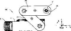
图1A-1C是依照本发明的一个实施例的机器人模块的视图;1A-1C are views of a robot module according to one embodiment of the present invention;
图2A和2B是依照本发明的一个实施例的图1A-1C中机器人模块的示意图;2A and 2B are schematic diagrams of the robotic module of FIGS. 1A-1C in accordance with one embodiment of the present invention;
图3A和3B是依照本发明的一个实施例的图1A-1C中机器人模块的示意图;3A and 3B are schematic diagrams of the robotic module of FIGS. 1A-1C in accordance with one embodiment of the present invention;
图4是依照本发明的一个实施例的图1A-1C中机器人模块的运动原理示意图;Fig. 4 is a schematic diagram of the movement principle of the robot module in Figs. 1A-1C according to an embodiment of the present invention;
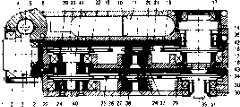
图5A和5B是依照本发明的一个实施例的图1A-1C中机器人模块的正视图和截面图;5A and 5B are front and cross-sectional views of the robot module of FIGS. 1A-1C in accordance with one embodiment of the present invention;
图6A和6B是依照本发明的一个实施例的图1A-1C中机器人模块的顶视图和断面图;6A and 6B are top and cross-sectional views of the robotic module of FIGS. 1A-1C in accordance with one embodiment of the present invention;
图7表示依照本发明的一个实施例的在CT导引之下的RCM模块;以及Figure 7 shows an RCM module under CT guidance according to one embodiment of the present invention; and
图8表示依照本发明的一个实施例的构造用于在CT导引之下的前列腺短距离治疗的RCM模块。Figure 8 shows an RCM module configured for CT-guided brachytherapy of the prostate in accordance with one embodiment of the present invention.
具体实施方式Detailed ways
参照下文中的说明和附图,将会对本发明的发明目的和技术特征有更清楚的了解。The purpose and technical features of the present invention will be more clearly understood with reference to the following description and accompanying drawings.
本发明提供了一种新颖的,用于执行图像辅助外科手术的设备和方法。本发明包括一个机器人装置或模块,它可用来为终端执行器的绕着两条相交于一固定几何点的轴线进行定向,上述固定几何点的位置远离该机械装置,具体的说是一个枢轴点,在本说明书中称之为运动遥控中心(RCM)。终端执行器,例如,是针驱动器之类的机器人工具,它可以安装在RCM模块上,并且能绕RCM点转动,而这个RCM点可以很方便地设置在终端执行器上,因为这个点远离机器人模块。The present invention provides a novel apparatus and method for performing image-assisted surgery. The present invention includes a robotic device or module that can be used to orient an end effector about two axes that intersect at a fixed geometric point located remote from the mechanical device, specifically a pivot point, referred to as the Remote Center for Motion (RCM) in this manual. An end effector, for example, is a robotic tool such as a needle drive, which can be mounted on the RCM module and can be turned around the RCM point, which is conveniently located on the end effector because this point is far away from the robot module.
本发明设计成在RCM几何点上重合的两根轴线具有两个旋转自由度(DOF)。枢轴的位置可以沿着一根轴线通过改变轴线之间的相对夹角进行调整,轴线之间的相对夹角在本申请中称为调整角。因此,这两种旋转不一定是正交的。The present invention is designed so that the two axes coincident at the geometric point of the RCM have two rotational degrees of freedom (DOF). The position of the pivot can be adjusted along an axis by changing the relative angle between the axes, and the relative angle between the axes is called an adjustment angle in this application. Therefore, the two rotations are not necessarily orthogonal.
现有技术的RCM机构存在运动学上的奇点,而本发明与现有技术RCM机构不同,它提供的双皮带传动结构有助于实现绕着两条轴线的无奇点的自由旋转。本发明还使终端执行器能够绕RCM装置的任意一个初始方向旋转,包括折叠方向、延伸方向,以及两者之间的任意方向。本发明在不同方向都能够表现出相同的机械性能。可以利用机械的和/或电子的装置来限制和设定所要求的运动范围。The RCM mechanism in the prior art has a kinematic singularity, but the present invention is different from the RCM mechanism in the prior art in that the double-belt transmission structure it provides helps realize free rotation around two axes without singularity. The present invention also enables the end effector to rotate about any of the initial orientations of the RCM device, including the folded orientation, the extended orientation, and any orientation in between. The present invention can exhibit the same mechanical properties in different directions. Mechanical and/or electronic means may be utilized to limit and set the desired range of motion.
图1A-1C分别表示依照本发明实施例的RCM模块的立体图、顶视图和正视图。这种模块或机构100包括第一、第二和第三臂(也称作联杆或联动部件)10、18和26。第一臂10与基座构件9相连,基座构件9可通过基轴1而固定在诸如固定支座或先前的机器人组件之类的基座上。第三臂26设计成用于容纳支承着终端执行器33的支架/驱动器32,而支架/驱动器32则连接在第三臂26的输出轴的任何一个侧面31或34上。使用了一个能适应不同用途的各种终端执行器的安装螺钉35。下面将更加详细地描述用于连接各种构件的连接装置。1A-1C show a perspective view, a top view and a front view, respectively, of an RCM module according to an embodiment of the present invention. Such a module or
装置100设计成具有两个有源的自由度:a)绕着代表第一旋转轴线,即基轴1的轴线xγ的转动α;和b)绕着代表第二旋转轴线y,即由臂18、26以及终端执行器(32-33)所构成的平行四边形构件3的轴线y的转动β。这两条轴线在xyz坐标系的中心,即代表该机构的枢轴点或RCM点上相交。The
装置100设计成能对构件9和10之间的调整角γ进行调整,而且可将构件9和10锁定在所希望的相对的方向上。调整角γ改变了轴线xγ的方向,并使RCM点的位置沿着第二旋转轴线y移动。这种角度调整设计方案便于设定枢轴点,以适应各种终端执行器,而同时又使设计保持紧凑。一个缺点是,正交旋转轴线(x&y|γ=0)变为非正交旋转轴线(xγ&y|γ>0)。这就减少了工作时包容的范围,并且,如有必要,还需要对轴线进行协调移动,以使终端执行器实现正交旋转运动。不过,对于小的调整角度而言,这种变化极微小。在测试过程中,若调整角γ为{0°,15°},则不会出现有关这种问题的困难。The
第二旋转轴线y是由用联杆18、26和终端执行器33/支架32所形成的模拟平行四边形装置来实现的。联杆18可相对于联杆10运动,而联杆26则保持其相对于联杆10的平行方向。终端执行器33/支架32(它刚性地固定在输出轴31、34上)保持其相对于联杆18的相对方向。输出轴31、34是可转动的,因此,终端执行器33/支架32相对于联杆26的方向是可以调整的。The second axis of rotation y is achieved by the simulated parallelogram arrangement formed by the
这种设计使终端执行器33/支架32能绕着远离这种机构的轴线y转动。实际上这是一种典型的RCM设计。本发明模块的新颖之处在于运动学方面的设计,以及用于实现平行四边形的机构。This design allows the
这两根旋转轴线都可进行无局限的运动,并且能够进行连续旋转。这一点对于完成多次转动并不很重要,但对于能进行不同作业模式却是非常重要的。机构100的初始(零)位置可设定在任意角度上,尤其是可设定在任意β角上,并且,在空间上可允许终端执行器从零设定方向的一侧转动到另一侧。图2A-2B和3A-3B分别描述了两个例子。Both axes of rotation allow unlimited movement and are capable of continuous rotation. This is not very important to accomplish multiple rotations, but it is very important to be able to perform different operating modes. The initial (zero) position of the
关于“折叠”初始位置的作业,β0=0°:图2A-2B分别表示这种模块的正视图,以及连同特定终端执行器33和支架32排在一起的顶视图。机构100的方向在β=β0=0°时用实线表示,而绕着模块的“折叠”位置转动时,则代表性地由两个β=β0±20°的虚线位置来表示。Regarding the operation of the "folded" initial position, β0 =0°: FIGS. 2A-2B show respectively a front view of such a module, and a top view lined up with a
图中所示的机构100安装成相对于地面呈倾斜状态(δ1>0°),以便把这个机构提升到高于RCM点。支架32支承着终端执行器33,所成的角度δ3=90°,而终端执行器相对于该机构的角度定位在δ2=δ3-δ3上,因此,在初始位置β=β0=0°时,终端执行器33是垂直的。The
图中所示的支架32连接在模块的外侧31上。把调整角调整到γ>0°,用以使RCM点沿y轴线平移,并将其定位在终端执行器33的顶端处。这样,RCM就是xγ&y|γ>0轴线的枢轴点。A
这种折叠作业方式(β0=0°)不仅能让模块避开RCM枢轴,还能让它避开RCM上方的区域。这对于完成图像导引程序而言很重要,此时,机器人装置必须远离显现图像的区域,以便目标和终端执行器在这一步骤中能够不受遮挡地显现成像。This folding operation (β0 =0°) not only allows the module to avoid the RCM pivot, but also allows it to avoid the area above the RCM. This is important to complete the image-guided procedure, where the robotic device must be kept away from the area where the image is visualized so that the target and end-effector can be visualized unobstructed during this step.
图3A-3B描述了一个实施例,其中的机构是绕着“非折叠”位置β=β0Z=90°转动的。在折叠的情形下,装置相对于地面是倾斜的(δ1>0°),以便降低RCM点高度。但是,终端执行器33是沿着支架安装的(δ3=0°,参见图3A),并且通过输出轴31和34的轴线,所以δ2=β(参见图3B)。在这个实施例中,初始方向要选择为使得终端执行器33处于竖直位置,角度β0=90°-δ1。而且,还可以通过将支架连接在模块的另一侧(内侧)34上,把支架32的结构做成与枢轴的方向互相正交(γ=0°)。当终端执行器33与联杆18因β角非常小而相互干涉时,也可以采用外侧安装方式,以避免干涉。这种β0接近90°的非折叠模式适合于这样的场合:在诸如机器人辅助腹腔镜检查之类的程序中,机器人模块位于RCM枢轴的上方不会妨碍到正常作业时。Figures 3A-3B depict an embodiment in which the mechanism is rotated about the "unfolded" position β = β0 Z = 90°. In folded condition, the device is tilted relative to the ground (δ1 >0°) in order to reduce the RCM point height. However,
因此,模块可以在折叠(β=0°)、垂直(β=90°)、反转(β=-90°)、伸展(β=180°)或任意非折叠位置(β{-90°,0°,90°,180°})上作业,并且将终端执行器33安装在该机构的任何一侧。以上所例举的典型的折叠作业模式和非折叠作业模式是两种对初始位置、模块取向、支架设计方案和侧面安装方式的优选配置,存在有许多种具备可能结构和应用特性的配置。Thus, the module can be in folded (β=0°), vertical (β=90°), inverted (β=-90°), extended (β=180°) or any unfolded position (β{-90°, 0°, 90°, 180°}) and install
图4描述了依照本发明实施例的RCM模块的运动设计思路。图中共有六根联杆(1、9、10、18、26、31)和五个旋转接头(2、8、17、22、30)。其中的一个接头是无源(γ角调整接头8)的,而另外三个接头(17、22、30)是通过皮带传送运动的,因此,这种机构只有两个有源的自由度(2、17-22-30)。Fig. 4 describes the motion design idea of the RCM module according to the embodiment of the present invention. There are six connecting rods (1, 9, 10, 18, 26, 31) and five rotary joints (2, 8, 17, 22, 30) among the figure. One of the joints is passive (gamma angle adjustment joint 8), while the other three joints (17, 22, 30) are driven by belts, so this mechanism has only two active degrees of freedom (2 , 17-22-30).
模块100由三个主要机构组成:基座角度调整机构,沿着倾斜方向xγ的转动α的第一枢轴旋转接头机构,以及虚拟平行四边形机构。The
基座角度的调整是通过改变模块100的构件9和10之间的角度来实现的,这两个构件用接头8连接。可以用一个凸圆柱形面和一个凹圆柱形面相配合,来构成旋转接头8,并可将其设定并锁定在所要求的方向上。The adjustment of the base angle is achieved by changing the angle between the
沿着倾斜方向xγ的转动α的第一枢轴旋转接头,是由在输入轴1和联杆9之间起作用的旋转接头2构成的。在这个优选实施例中,这个接头是由蜗杆传动机构3-4驱动的,而蜗轮3安装在输入轴1上。这种蜗杆传动机构可以采用2002年10月16日提出的美国专利申请60/339247中所描述的贝尔—蜗杆(Bail-Worm)型机构,该申请的发明名称为“小型贝尔—蜗杆传动机构”(Miniature Ball-Worm Transmission),该申请的全部内容可作为本申请的参考。The first pivotal swivel joint of rotation α along the direction of inclination xγ is constituted by the swivel joint 2 acting between the
第一轴线上的驱动电机11通过锥齿轮传动机构6-7驱动蜗杆4。这些构件是这样安装的,即,使得调整接头8、蜗杆4和锥齿轮6都共轴线。蜗杆4与锥齿轮6互相刚性地连接在一起,并且由一组设置在联杆9的凸接头表面中心处的轴承5支承。这种运动链能保证,无论调整接头8处于任何设定位置γ上,驱动电机11的运动都能传递给输出轴1。这样,驱动电机11就能与其它旋转轴的驱动电机12一起,紧凑地设置在基座联杆10上。The driving
虚拟平行四边形机构由剩余的其它构件构成。为了清楚起见,图4表示了第二旋转轴线的β=90°角时的模块。平行四边形(从图1C和图3B的正视图可以更清楚地看到其呈现的形状)是由联杆18、26和支架32和/或终端执行器33构成的。这个平行四边形的三个连接接头是17、22和30,而第四个连接头是虚构的点,即第二RCM枢轴点。在该RCM的模型中,平行四边形的边长相等,都是100mm。唯一的一个被驱动的接头是17,而另外两个接头都通过无滑移的,传动比为1∶1的皮带传动机构,即,由两根皮带19和25(同步皮带、链条、锚链、缆线传动、金属带等)与接头17连接。The virtual parallelogram mechanism is formed by remaining other components. For the sake of clarity, FIG. 4 shows the module at an angle β=90° of the second axis of rotation. A parallelogram (which is more clearly seen in its assumed shape from the front view of FIGS. 1C and 3B ) is formed by
旋转接头17在联杆10与18之间起作用,通过蜗轮—蜗杆机构13-14而啮合连接在一起,由安装在联杆10中的电机12驱动,而蜗杆13则由轴承组15支承。通常,蜗轮—蜗杆机构13-14采用专利申请60/339247中所记述的机构。The swivel joint 17 acts between the
可采用反向皮带轮装置的设计方案,利用两个根皮带传动而不是传统的四元杆络机构来实现平行四边形机构的运动。在这种情况下,电机使联杆18转动一个角度β;在任何转动角度β下,联杆26与基座10保持平行;而输出轴31保持其与联杆18平行的方向(保持平行)。这样,蜗轮14就使联杆18而不是使安装在基座构件10上的皮带轮16转动。因此,由安装在轴承20上的惰轮21张紧的第一皮带19的第一皮带19的第二皮带轮23,保持其相对于基座构件10的方向。然后,将类似的反向皮带轮装置用做平行四边形的第二边26和第三边31。联杆26通过一根轴连接在皮带轮23上,从而与基座构件10保持平行,而第二皮带25的第一皮带轮24则与前面说到的联杆18相连。由轴承20支承的惰轮21将联接第二皮带轮29的皮带25张紧。通过这种方式,固定在输出轴31上的皮带轮29便保持其相对于联杆18的方向,把虚拟的平行四边形机构封闭起来。The design scheme of the reverse pulley device can be adopted, and the movement of the parallelogram mechanism can be realized by using two belt drives instead of the traditional four-way rod network mechanism. In this case, the motor rotates the
这种组合运动设计方案实现了在RCM点上的轴线非正交xγ&y|γ>0的可调整枢轴RCM机构,它具有双面的终端执行器安装座架,能绕着任意β角(折叠、垂直、伸展、翻转,或者一般的非折叠位置)进行作业。This combined motion design scheme realizes the adjustable pivot RCM mechanism with non-orthogonal axis xγ &y|γ>0 on the RCM point, which has a double-sided end effector mounting bracket, which can rotate around any β angle (folded, vertical, extended, flipped, or generally non-folded position) to perform the job.
本发明的某些机械结构特征示于图5A-5B。图5A-5B是具有正交枢轴配置(γ=0°)的RCM模块100处于折叠位置(β=0°)上的正视图,和沿中心剖切的A-A截面图。图5A-5B显示了本发明的采用滚珠蜗杆机构的Certain mechanical features of the present invention are shown in Figures 5A-5B. 5A-5B are front elevational views and A-A sectional views cut through the center of the
实施例。Example.
如图5A-5B所示,在滚珠蜗杆机构实施例中,蜗轮3和14分别在它们的轴1和35上加工出来。在典型的蜗杆机构的实施例中,蜗轮都通过压配合方式用一个长键固定安装在轴上。As shown in Figures 5A-5B, in the ball and screw mechanism embodiment,
用于实现运动学设计方案的接头的轴承(图4)都标以与图5b中相同的标号。例如,轴1用两个轴承2支承。联杆9和10之间的基本角度y的调整接头γ,以及与蜗杆4的轴线的同轴线,都很清楚地表示在A-A截面图中。联杆18和26可以分别用薄的盖子42和43加以覆盖。The bearings (Fig. 4) of the joints used to realize the kinematic design are given the same reference numbers as in Fig. 5b. For example, the
图5B还表示了皮带19和25的反向皮带轮装置。皮带轮16固定在基座10上,而蜗轮14与联杆18连接。同样,皮带轮24安装在联杆18上,而皮带轮23与联杆26连接。所有的皮带分别使用安装在轴承20和27上,并由偏心轴37和38支承的的惰轮21和28来张紧,然后用平头螺钉锁紧。Figure 5B also shows the reverse pulley arrangement of the
在运动接头22的高度上调整角度体是在装配过程中调整联杆18和26之间的角度同时完成的,结果,联杆26与基座联杆10平行。这样就能把这些皮带轮以任意初始方向安装在轴上,以便张紧皮带,并起到皮带的“定时”作用。这种机构允许对皮带轮23和联杆26之间的角度进行调整,并将其锁定在所要求的方向上。这样,皮带轮23安装在与轴40呈锥面配合的轴39上,而轴40则安装在联杆26上。调整是通过设定轴39和40之间的相对角度了完成的,并用螺钉41将其锁定。Adjustment of the angled body in the height of the kinematic joint 22 is accomplished while adjusting the angle between the
输出轴是对称结构,因此能够用螺钉35将终端执行器支架安装在31或34任何一侧的锥面上。图5B表示从轴34的侧面31安装的螺钉35,用以将支架固定在轴的侧面31(外侧)上。当要将终端执行器支架安装在另一侧(内侧)时,则把螺钉35反过来安装,使螺钉头位于轴的侧面31上。The output shaft is a symmetrical structure, so the end effector bracket can be mounted on the tapered surface on either side of 31 or 34 with
图6A和6B表示模块的顶视图和通过调整接头中心的B-B断面图。这种机构的基座调整角取中间值,γ=7.5°,而且机构处于β=0°的折叠位置。Figures 6A and 6B show a top view of the module and a B-B sectional view through the center of the alignment joint. The base adjustment angle of this mechanism takes an intermediate value, γ=7.5°, and the mechanism is in the folded position of β=0°.
图6B表示基座调整装置及其两侧的张紧机构,张紧机构包括板46、定位销47和锥形头定位螺钉48。将定位销47插入具有轴线与调整接头8的轴线平行的径向槽49的联杆9中。通过这种方式,定位销47就能在槽中摆动,调整定位销47在槽中的位置,于是张紧板46便保持在接头8表面上的法线方向上。这样,就用定位销47将板46的一端固定在联杆9内。在板46的另一端有一个与锥形头定位螺钉48的锥形部分相啮合的孔,锥形头定位螺钉48用螺纹拧在联杆10内。这个定位螺钉48的作用就像在锥形头定位螺钉48的锥面与板46的孔之间的一个楔块。如果松开联杆10两侧的定位螺钉48,则板46就松开,调整接头8不锁定,反之,则锁定调整接头8。FIG. 6B shows the base adjustment device and the tensioning mechanism on both sides thereof. The tensioning mechanism includes a plate 46 , a positioning pin 47 and a conical head positioning screw 48 . The positioning pin 47 is inserted into the
图6B还表示了紧凑地设置在联杆10主体内的驱动电机11和12的位置,而电机罩盖44则让人很快就能接近电机。所有包含在第二原型中的电子元件、电机连接器,以及冗余编码器连接部件都紧挨着电机,设置在联杆10的空腔内。电缆通过罩盖44上开设的孔45伸出去。Figure 6B also shows the location of the
依照本发明的实施例,RCM模块可以是滚珠蜗杆RCM(BW-RCM),即,是一种能让转轴点离开机构100mm的,外科手术用的机器人模块。BW-RCM的结构设计紧凑,可以折叠成很小的体积,而且重量非常轻(例如,尺寸只有175×68×54mm,重仅1.35Kg)。BW-RCM可以对外科器械的空间位置进行精确定向,同时使其中的一点保持位置不变。According to an embodiment of the present invention, the RCM module may be a ball-worm RCM (BW-RCM), that is, a robotic module for surgical operations that allows the pivot point to be 100mm away from the mechanism. The BW-RCM has a compact structure design, can be folded into a small volume, and is very light in weight (for example, the size is only 175×68×54mm, and the weight is only 1.35Kg). BW-RCM can precisely orient the spatial position of surgical instruments while keeping one point in place.
本发明的RCM模块的运动学结构设计使其适合应用于在经由皮肤的手术中要求伤口最小的手术,以及套管针/针的定向。本发明的RCM模块适合于各种终端执行器。例如,这种RCM可与肾脏穿刺(PAKY)射线透射针驱动器联合使用(参见26.Stoianovici D,Cadeddu JA,Demaree RD,Basile HA,Taylor RH,Whitcomb LL,Sharpe WN,Kavoussi LR:An EfficientNeedle Injection Technique and Radiological Guidance Method forPercutaneous Procedures.Lecture!Vote in Computer Science,1997CVRNled-MRCAS’,Springer-Verlag,1997;1205:295-298;Stoianovici D,Cadeddu JA,Demaree RD,Basile HA,Taylor RH,Whitcomb LL,KavoussiLR:A Novel Mechanical Transmission Applied to Percutaneous Renal Access.Proceedings of the ASME Dynamic Systems and Control Division,1997;DSC-61:401-406;以及Stoianovici D,Kavoussi LR,Whitcomb LL,Taylor RH,Cadeddu JA,Basile HA,Demaree RD.(1996),“Friction Transmission withAxial Loading and a Radiolucent Surgical Needle Drive”,由Johns HopkinsUniversity于1998年2月20日作为PCT申请提出的美国发明专利60/038115。1998年2月20日提交的处于审查过程中的美国专利申请09/026669。已公布的PCT文献WO98/36688;所有这些文献都作为本说明书的参考文献),用以完成用图像导向的肾穿刺。这种机器人装置可以借助于C-Arm成像器的X-射线荧光透视的导引而对针进行定向并插入针,就象由外科医生控制的那样。这种模块利用PAKY射线透射针驱动器,绕着折叠位置β=0°进行作业,因此避开了X-射线区域,并且使用了基座调整角γ=9.3°,因此产生非正交枢轴。这种装置用于肾穿刺,针的定位精度毫无疑问得以提高,且手术时间也缩短了,因此减少了病人和泌尿科医师接受辐射的量。The kinematic design of the RCM module of the present invention makes it suitable for applications requiring minimal trauma in percutaneous procedures, as well as trocar/needle orientation. The RCM module of the present invention is suitable for various end effectors. For example, this RCM can be used in combination with radiolucent needle drivers for renal aspiration (PAKY) (see 26. Stoianovici D, Cadeddu JA, Demaree RD, Basile HA, Taylor RH, Whitcomb LL, Sharpe WN, Kavoussi LR: An Efficient Needle Injection Technique and Radiological Guidance Method for Percutaneous Procedures.Lecture! Vote in Computer Science, 1997CVRNled-MRCAS', Springer-Verlag, 1997; 1205:295-298; Stoianovici D, Cadeddu JA, Demaree RD, Basile HA, Taylor LHLL, Whitcombous : A Novel Mechanical Transmission Applied to Percutaneous Renal Access. Proceedings of the ASME Dynamic Systems and Control Division, 1997; DSC-61: 401-406; and Stoianovici D, Kavoussi LR, Whitcomb LL, Taylor RH, Cadeddu HA, Basile Demaree RD. (1996), "Friction Transmission with Axial Loading and a Radiolucent Surgical Needle Drive", U.S. Patent 60/038115 filed as PCT application on February 20, 1998 by Johns Hopkins University. Filed February 20, 1998 Pending US patent application 09/026669. Published PCT document WO98/36688; all of which are incorporated herein by reference) for image-guided renal biopsy. This robotic device can orient and insert the needle with the help of X-ray fluoroscopic guidance of the C-Arm imager, as controlled by the surgeon. This module utilizes a PAKY radiolucent needle driver, operates around a folded position β = 0°, thus avoiding the X-ray field, and uses a base adjustment angle γ = 9.3°, thus creating a non-orthogonal pivot. This device is used for renal puncture, the accuracy of needle positioning is undoubtedly improved, and the operation time is also shortened, thereby reducing the amount of radiation received by the patient and the urologist.
本发明的RCM模块可与专用针驱动器一起,用于计算机X射线体层照相(CT)的定位。Z-Stage PAKY是PAKY针驱动器的改进型,除了适用于PAKY的针驱动特性之外,还适用于实现CT/MRI定位方法,它是与JohnsHopkins大学的Computer Integrated Surgical Systems and Technology(CISST)的NSF Engineering Research Center以及东京大学协作制造的[13,I-6,20]。当使用PAKY驱动器时,RCM还可以在轴线非正交的折叠模式下进行作业。The RCM module of the present invention can be used with dedicated needle drivers for positioning in computed tomography (CT). Z-Stage PAKY is an improved version of PAKY needle driver. In addition to the needle drive characteristics of PAKY, it is also suitable for realizing CT/MRI positioning methods. It is an NSF with Computer Integrated Surgical Systems and Technology (CISST) of Johns Hopkins University Engineering Research Center and the University of Tokyo collaborated [13, I-6, 20]. When using the PAKY drive, the RCM can also operate in a folded mode with non-orthogonal axes.
图7表示在CT导引之下,本发明的RCM模块用于肾和脊椎穿刺手术,利用简便方法实现在CT和MR成像系统中的机器人定位。该方法使用在任意CT扫描器中都方便获取的激光定标器,且不必成像,因此减少了对人的辐射。与人工方法不同,对于皮肤刺入点和靶目标处于不同的断层切片上的情形,该方法允许执行倾斜插入。Fig. 7 shows that under CT guidance, the RCM module of the present invention is used in renal and spinal puncture operations, and realizes robot positioning in CT and MR imaging systems with a simple method. The method uses laser scalers that are readily available in any CT scanner and does not require imaging, thus reducing radiation exposure to humans. Unlike manual methods, this method allows for oblique insertions where the skin penetration point and target are on different tomographic slices.
用于CT导引手术作业的包含有RCM的高自由度机器人系统已经不断发展。图8显示了用于CT导引的肾穿刺的这种装置。从图8可知,在这个实施例中,机器人装置仍为折叠的非正交作业模式(β=0°,γ=9.3°),但是其垂直放置由会阴进入,基座倾斜角度(图2)δ1=90°。High-degree-of-freedom robotic systems incorporating RCMs for CT-guided surgical procedures have been developed. Figure 8 shows such a device for CT-guided renal biopsy. It can be seen from Fig. 8 that in this embodiment, the robot device is still in the folded non-orthogonal working mode (β=0°, γ=9.3°), but its vertical placement is entered by the perineum, and the base is inclined at an angle (Fig. 2) δ1 =90°.
因此,以上上述的RCM模块是一种结构紧凑的机器人模块,能够在空间上绕着远离机构的枢轴点在两个方向上对终端执行器进行定向。远离枢轴点的运动的应用领域包括工业领域,但更重要的是外科手术作业领域,因为在人工外科手术中通常都会涉及到这种类型的运动。这种模块能适应各种终端执行器和作业模式,可以灵活应用。由多模块装置实现的多种临床应用显示了RCM的多功能性,应用在外科上既实用又安全。Thus, the RCM module described above is a compact robotic module capable of orienting the end effector in two directions spatially about a pivot point remote from the mechanism. Applications for motion away from the pivot point include industry, but more importantly surgical operations, since this type of motion is often involved in manual surgery. This module can be adapted to various end effectors and operation modes, and can be applied flexibly. The multiple clinical applications enabled by the multi-modular device demonstrate the versatility of the RCM, which is both practical and safe for surgical applications.
本发明参照附图对实施例进行了充分的描述,因此,显而易见,在不脱离本发明在权利要求书所限定的范围和构思的前提下,可以对本发明以及上述的实施例进行各种变化和改进。The present invention has fully described the embodiments with reference to the accompanying drawings. Therefore, it is obvious that various changes and changes can be made to the present invention and the above-mentioned embodiments without departing from the scope and concept of the present invention defined in the claims. Improve.
Claims (30)
Applications Claiming Priority (2)
| Application Number | Priority Date | Filing Date | Title |
|---|---|---|---|
| US35465602P | 2002-02-06 | 2002-02-06 | |
| US60/354,656 | 2002-02-06 |
Publications (2)
| Publication Number | Publication Date |
|---|---|
| CN1642696Atrue CN1642696A (en) | 2005-07-20 |
| CN100349705C CN100349705C (en) | 2007-11-21 |
Family
ID=27734404
Family Applications (1)
| Application Number | Title | Priority Date | Filing Date |
|---|---|---|---|
| CNB038063514AExpired - LifetimeCN100349705C (en) | 2002-02-06 | 2003-02-06 | Remote center of motion robotic system and method |
Country Status (7)
| Country | Link |
|---|---|
| US (1) | US7021173B2 (en) |
| EP (1) | EP1472579B1 (en) |
| JP (1) | JP2005516786A (en) |
| CN (1) | CN100349705C (en) |
| AU (1) | AU2003214837B2 (en) |
| CA (1) | CA2475239C (en) |
| WO (1) | WO2003067341A2 (en) |
Cited By (19)
| Publication number | Priority date | Publication date | Assignee | Title |
|---|---|---|---|---|
| CN100425409C (en)* | 2006-12-13 | 2008-10-15 | 北京航空航天大学 | Rope-driven two-dimensional virtual center rotation mechanism |
| CN102026781A (en)* | 2008-05-15 | 2011-04-20 | 波音公司 | Robot system comprising a foldable robot arm |
| CN102229145A (en)* | 2011-06-23 | 2011-11-02 | 哈尔滨工程大学 | Secondary oscillating joint structure of underwater electric manipulator |
| CN101708129B (en)* | 2009-11-04 | 2012-05-09 | 温州医学院 | Remote-control apparatus for alimentary tract endoscope interventional treatment |
| CN103170987A (en)* | 2011-12-21 | 2013-06-26 | 中国科学院沈阳自动化研究所 | Planet surface mechanical arm sampling device |
| CN104349742A (en)* | 2012-06-01 | 2015-02-11 | 直观外科手术操作公司 | Redundant axes and degrees of freedom for hardware-constrained telecentric robotic manipulators |
| CN105832412A (en)* | 2015-01-12 | 2016-08-10 | 上银科技股份有限公司 | Endoscope positioning method and auxiliary positioning device used by same |
| CN106002931A (en)* | 2015-03-31 | 2016-10-12 | 精工爱普生株式会社 | Robot system |
| CN106002929A (en)* | 2015-03-31 | 2016-10-12 | 精工爱普生株式会社 | Robot system |
| CN106002930A (en)* | 2015-03-31 | 2016-10-12 | 精工爱普生株式会社 | Robot and robot system |
| CN106493729A (en)* | 2015-09-07 | 2017-03-15 | 精工爱普生株式会社 | robot, control device and robot system |
| CN106572887A (en)* | 2014-07-15 | 2017-04-19 | 皇家飞利浦有限公司 | Image integration and robotic endoscope control in X-ray suite |
| CN107053252A (en)* | 2015-10-30 | 2017-08-18 | 精工爱普生株式会社 | Robot |
| CN107538477A (en)* | 2016-06-29 | 2018-01-05 | 精工爱普生株式会社 | robot, control device and robot system |
| CN107639627A (en)* | 2017-09-29 | 2018-01-30 | 重庆金山医疗器械有限公司 | Parallelogram drive mechanism |
| CN109394342A (en)* | 2018-12-18 | 2019-03-01 | 中国科学院苏州生物医学工程技术研究所 | The inserting needle device of Needle-driven Robot based on double parallel quadrangle RCM mechanism |
| CN109788994A (en)* | 2016-10-18 | 2019-05-21 | 直观外科手术操作公司 | Computer assisted remote operation surgery systems and method |
| CN111227940A (en)* | 2020-01-23 | 2020-06-05 | 诺创智能医疗科技(杭州)有限公司 | Surgical Manipulator and Surgical Robot |
| CN114504427A (en)* | 2021-10-03 | 2022-05-17 | 崔迪 | Ophthalmic surgery robot and ophthalmic surgery equipment |
Families Citing this family (141)
| Publication number | Priority date | Publication date | Assignee | Title |
|---|---|---|---|---|
| US9050119B2 (en) | 2005-12-20 | 2015-06-09 | Intuitive Surgical Operations, Inc. | Cable tensioning in a robotic surgical system |
| US6626899B2 (en) | 1999-06-25 | 2003-09-30 | Nidus Medical, Llc | Apparatus and methods for treating tissue |
| US7594912B2 (en) | 2004-09-30 | 2009-09-29 | Intuitive Surgical, Inc. | Offset remote center manipulator for robotic surgery |
| US8768516B2 (en) | 2009-06-30 | 2014-07-01 | Intuitive Surgical Operations, Inc. | Control of medical robotic system manipulator about kinematic singularities |
| US7766894B2 (en) | 2001-02-15 | 2010-08-03 | Hansen Medical, Inc. | Coaxial catheter system |
| US8414505B1 (en) | 2001-02-15 | 2013-04-09 | Hansen Medical, Inc. | Catheter driver system |
| US7594917B2 (en) | 2001-03-13 | 2009-09-29 | Ethicon, Inc. | Method and apparatus for fixing a graft in a bone tunnel |
| US7195642B2 (en)* | 2001-03-13 | 2007-03-27 | Mckernan Daniel J | Method and apparatus for fixing a graft in a bone tunnel |
| US6517546B2 (en)* | 2001-03-13 | 2003-02-11 | Gregory R. Whittaker | Method and apparatus for fixing a graft in a bone tunnel |
| US7331967B2 (en)* | 2002-09-09 | 2008-02-19 | Hansen Medical, Inc. | Surgical instrument coupling mechanism |
| US6840127B2 (en)* | 2003-02-05 | 2005-01-11 | Michael Julius Moran | Tendon link mechanism with six degrees of freedom |
| US8007511B2 (en) | 2003-06-06 | 2011-08-30 | Hansen Medical, Inc. | Surgical instrument design |
| WO2005087128A1 (en) | 2004-03-05 | 2005-09-22 | Hansen Medical, Inc. | Robotic catheter system |
| US7976539B2 (en)* | 2004-03-05 | 2011-07-12 | Hansen Medical, Inc. | System and method for denaturing and fixing collagenous tissue |
| US7971505B2 (en)* | 2004-03-11 | 2011-07-05 | Ntn Corporation | Link actuating device |
| US20050267359A1 (en)* | 2004-05-27 | 2005-12-01 | General Electric Company | System, method, and article of manufacture for guiding an end effector to a target position within a person |
| US10646292B2 (en) | 2004-09-30 | 2020-05-12 | Intuitive Surgical Operations, Inc. | Electro-mechanical strap stack in robotic arms |
| US9261172B2 (en)* | 2004-09-30 | 2016-02-16 | Intuitive Surgical Operations, Inc. | Multi-ply strap drive trains for surgical robotic arms |
| US7763015B2 (en)* | 2005-01-24 | 2010-07-27 | Intuitive Surgical Operations, Inc. | Modular manipulator support for robotic surgery |
| WO2006081409A2 (en)* | 2005-01-28 | 2006-08-03 | Massachusetts General Hospital | Guidance and insertion system |
| JP2009500086A (en) | 2005-07-01 | 2009-01-08 | ハンセン メディカル,インク. | Robotic guide catheter system |
| GB0521281D0 (en)* | 2005-10-19 | 2005-11-30 | Acrobat Company The Ltd | hybrid constrant mechanism |
| US20100228096A1 (en)* | 2009-03-06 | 2010-09-09 | Ethicon Endo-Surgery, Inc. | Methods and devices for providing access into a body cavity |
| KR101477133B1 (en) | 2006-06-13 | 2014-12-29 | 인튜어티브 서지컬 인코포레이티드 | Minimally invasive surgical system |
| WO2007147232A1 (en) | 2006-06-19 | 2007-12-27 | Robarts Research Institute | Apparatus for guiding a medical tool |
| US8900306B2 (en) | 2006-09-26 | 2014-12-02 | DePuy Synthes Products, LLC | Nucleus anti-expulsion devices and methods |
| US8444631B2 (en) | 2007-06-14 | 2013-05-21 | Macdonald Dettwiler & Associates Inc | Surgical manipulator |
| CA2709634C (en)* | 2007-12-21 | 2017-04-25 | Benny Hon Bun Yeung | Surgical manipulator |
| US9610131B2 (en)* | 2008-11-05 | 2017-04-04 | The Johns Hopkins University | Rotating needle driver and apparatuses and methods related thereto |
| US20100126293A1 (en)* | 2008-11-21 | 2010-05-27 | Comau Inc. | Robotic radial tool positioning system |
| US9737334B2 (en) | 2009-03-06 | 2017-08-22 | Ethicon Llc | Methods and devices for accessing a body cavity |
| US20100228090A1 (en)* | 2009-03-06 | 2010-09-09 | Ethicon Endo-Surgery, Inc. | Methods and devices for providing access into a body cavity |
| US9254123B2 (en) | 2009-04-29 | 2016-02-09 | Hansen Medical, Inc. | Flexible and steerable elongate instruments with shape control and support elements |
| GB0908368D0 (en) | 2009-05-15 | 2009-06-24 | Univ Leuven Kath | Adjustable remote center of motion positioner |
| US20120067354A1 (en) | 2009-06-03 | 2012-03-22 | Moog B.V. | Skewed-axis three degree-of-freedom remote-center gimbal |
| CN102029608A (en)* | 2009-09-24 | 2011-04-27 | 鸿富锦精密工业(深圳)有限公司 | Robot |
| US9474540B2 (en) | 2009-10-08 | 2016-10-25 | Ethicon-Endo-Surgery, Inc. | Laparoscopic device with compound angulation |
| SE533512C2 (en)* | 2009-10-30 | 2010-10-12 | Olaf Ruppel | Adjustable arm for grippers |
| US8376938B2 (en)* | 2009-11-20 | 2013-02-19 | Ethicon Endo-Surgery, Inc. | Discrete flexion head for single port device |
| US8414483B2 (en)* | 2009-12-11 | 2013-04-09 | Ethicon Endo-Surgery, Inc. | Methods and devices for providing access into a body cavity |
| US8517932B2 (en)* | 2009-12-11 | 2013-08-27 | Ethicon Endo-Surgery, Inc. | Methods and devices for providing access through tissue to a surgical site |
| US8357088B2 (en)* | 2009-12-11 | 2013-01-22 | Ethicon Endo-Surgery, Inc. | Methods and devices for providing access into a body cavity |
| US8435174B2 (en)* | 2009-12-11 | 2013-05-07 | Ethicon Endo-Surgery, Inc. | Methods and devices for accessing a body cavity |
| US8282546B2 (en)* | 2009-12-11 | 2012-10-09 | Ethicon Endo-Surgery, Inc. | Inverted conical expandable retractor with coil spring |
| US8460186B2 (en)* | 2009-12-11 | 2013-06-11 | Ethicon Endo-Surgery, Inc. | Methods and devices for providing access through tissue to a surgical site |
| US8231570B2 (en)* | 2009-12-11 | 2012-07-31 | Ethicon Endo-Surgery, Inc. | Inverted conical expandable retractor |
| US8444557B2 (en)* | 2009-12-11 | 2013-05-21 | Ethicon Endo-Surgery, Inc. | Methods and devices for providing access through tissue to a surgical site |
| US8353873B2 (en)* | 2009-12-11 | 2013-01-15 | Ethicon Endo-Surgery, Inc. | Methods and devices for providing access through tissue to a surgical site |
| US8500633B2 (en)* | 2009-12-11 | 2013-08-06 | Ethicon Endo-Surgery, Inc. | Methods and devices for providing surgical access through tissue to a surgical site |
| IT1399603B1 (en)* | 2010-04-26 | 2013-04-26 | Scuola Superiore Di Studi Universitari E Di Perfez | ROBOTIC SYSTEM FOR MINIMUM INVASIVE SURGERY INTERVENTIONS |
| US9226760B2 (en) | 2010-05-07 | 2016-01-05 | Ethicon Endo-Surgery, Inc. | Laparoscopic devices with flexible actuation mechanisms |
| US8562592B2 (en) | 2010-05-07 | 2013-10-22 | Ethicon Endo-Surgery, Inc. | Compound angle laparoscopic methods and devices |
| KR101205364B1 (en)* | 2010-05-13 | 2012-11-28 | 삼성중공업 주식회사 | Industrial manipulators having attachable and detachable 4-bar-linkage-typed mechanical driving module |
| KR101550451B1 (en)* | 2010-08-10 | 2015-09-07 | (주)미래컴퍼니 | RCM structure of surgical robot arm |
| WO2011149260A2 (en)* | 2010-05-28 | 2011-12-01 | 주식회사 이턴 | Rcm structure for a surgical robot arm |
| US8460337B2 (en) | 2010-06-09 | 2013-06-11 | Ethicon Endo-Surgery, Inc. | Selectable handle biasing |
| WO2012020386A1 (en) | 2010-08-11 | 2012-02-16 | Ecole Polytechnique Federale De Lausanne (Epfl) | Mechanical positioning system for surgical instruments |
| CA2713053A1 (en) | 2010-08-12 | 2012-02-12 | Socpra-Sciences Et Genie S.E.C. | Device for orienting an object according to a given spatial orientation |
| CN102371590A (en)* | 2010-08-25 | 2012-03-14 | 鸿富锦精密工业(深圳)有限公司 | Arm structure of robot |
| EP2627278B1 (en) | 2010-10-11 | 2015-03-25 | Ecole Polytechnique Fédérale de Lausanne (EPFL) | Mechanical manipulator for surgical instruments |
| WO2013014621A2 (en) | 2011-07-27 | 2013-01-31 | Ecole Polytechnique Federale De Lausanne (Epfl) | Mechanical teleoperated device for remote manipulation |
| US12402960B2 (en) | 2010-10-11 | 2025-09-02 | Ecole Polytechnique Federale De Lausanne (Epfl) | Mechanical manipulator for surgical instruments |
| US8603078B2 (en) | 2010-10-13 | 2013-12-10 | Ethicon Endo-Surgery, Inc. | Methods and devices for guiding and supporting surgical instruments |
| US20140039314A1 (en)* | 2010-11-11 | 2014-02-06 | The Johns Hopkins University | Remote Center of Motion Robot for Medical Image Scanning and Image-Guided Targeting |
| US20120191079A1 (en) | 2011-01-20 | 2012-07-26 | Hansen Medical, Inc. | System and method for endoluminal and translumenal therapy |
| US20130030363A1 (en) | 2011-07-29 | 2013-01-31 | Hansen Medical, Inc. | Systems and methods utilizing shape sensing fibers |
| JP2014529423A (en) | 2011-08-11 | 2014-11-13 | ザ ボード オブ トラスティーズ オブ ザ レランド スタンフォード ジュニア ユニバーシティー | Remote heart mechanism and method of using the same |
| US8617176B2 (en) | 2011-08-24 | 2013-12-31 | Depuy Mitek, Llc | Cross pinning guide devices and methods |
| US9956042B2 (en) | 2012-01-13 | 2018-05-01 | Vanderbilt University | Systems and methods for robot-assisted transurethral exploration and intervention |
| US9539726B2 (en)* | 2012-04-20 | 2017-01-10 | Vanderbilt University | Systems and methods for safe compliant insertion and hybrid force/motion telemanipulation of continuum robots |
| WO2013158983A1 (en) | 2012-04-20 | 2013-10-24 | Vanderbilt University | Robotic device for establishing access channel |
| US9687303B2 (en) | 2012-04-20 | 2017-06-27 | Vanderbilt University | Dexterous wrists for surgical intervention |
| EP3915504A1 (en)* | 2012-06-01 | 2021-12-01 | Intuitive Surgical Operations, Inc. | Surgical instrument manipulator aspects |
| EP4070755A1 (en)* | 2012-06-01 | 2022-10-12 | Intuitive Surgical Operations, Inc. | Multi-port surgical robotic system architecture |
| EP2879609B2 (en) | 2012-08-02 | 2022-12-21 | Koninklijke Philips N.V. | Controller definition of a robotic remote center of motion |
| CN102922509A (en)* | 2012-09-27 | 2013-02-13 | 北京航空航天大学 | Modularized two-DOF (Degree of Freedom) parallel mechanism with virtual rotating center |
| US20140148673A1 (en) | 2012-11-28 | 2014-05-29 | Hansen Medical, Inc. | Method of anchoring pullwire directly articulatable region in catheter |
| US9326822B2 (en) | 2013-03-14 | 2016-05-03 | Hansen Medical, Inc. | Active drives for robotic catheter manipulators |
| US20140277334A1 (en) | 2013-03-14 | 2014-09-18 | Hansen Medical, Inc. | Active drives for robotic catheter manipulators |
| US20140276936A1 (en) | 2013-03-15 | 2014-09-18 | Hansen Medical, Inc. | Active drive mechanism for simultaneous rotation and translation |
| US9408669B2 (en) | 2013-03-15 | 2016-08-09 | Hansen Medical, Inc. | Active drive mechanism with finite range of motion |
| US9782198B2 (en) | 2013-03-28 | 2017-10-10 | Koninklijke Philips N.V. | Localization of robotic remote center of motion point using custom trocar |
| CN106659540B (en)* | 2014-02-03 | 2019-03-05 | 迪斯塔莫申股份公司 | Mechanical teleoperated devices including interchangeable distal instruments |
| WO2015118422A1 (en)* | 2014-02-04 | 2015-08-13 | Koninklijke Philips N.V. | Remote center of motion definition using light sources for robot systems |
| US10046140B2 (en) | 2014-04-21 | 2018-08-14 | Hansen Medical, Inc. | Devices, systems, and methods for controlling active drive systems |
| US9549781B2 (en) | 2014-05-30 | 2017-01-24 | The Johns Hopkins University | Multi-force sensing surgical instrument and method of use for robotic surgical systems |
| EP3185808B1 (en) | 2014-08-27 | 2022-02-23 | DistalMotion SA | Surgical system for microsurgical techniques |
| CN107073707B (en)* | 2014-09-30 | 2021-06-04 | 精工爱普生株式会社 | robot |
| EP3232951B1 (en) | 2014-12-19 | 2023-10-25 | DistalMotion SA | Surgical instrument with articulated end-effector |
| WO2016097861A1 (en) | 2014-12-19 | 2016-06-23 | Distalmotion Sa | Sterile interface for articulated surgical instruments |
| WO2016097871A1 (en) | 2014-12-19 | 2016-06-23 | Distalmotion Sa | Docking system for mechanical telemanipulator |
| WO2016097873A2 (en) | 2014-12-19 | 2016-06-23 | Distalmotion Sa | Articulated handle for mechanical telemanipulator |
| EP3653145B1 (en) | 2014-12-19 | 2024-01-24 | DistalMotion SA | Reusable surgical instrument for minimally invasive procedures |
| DE102015101018A1 (en) | 2015-01-23 | 2016-07-28 | MAQUET GmbH | Device for holding and moving a laparoscope during an operation |
| KR101666103B1 (en)* | 2015-02-02 | 2016-10-13 | 하이윈 테크놀로지스 코포레이션 | Method for positioning endoscope and auxiliary device for same method |
| JP6677970B2 (en)* | 2015-02-20 | 2020-04-08 | 川崎重工業株式会社 | Industrial robot |
| JP6582491B2 (en)* | 2015-03-31 | 2019-10-02 | セイコーエプソン株式会社 | robot |
| JP2016190294A (en)* | 2015-03-31 | 2016-11-10 | セイコーエプソン株式会社 | Robot system |
| JP2016190296A (en)* | 2015-03-31 | 2016-11-10 | セイコーエプソン株式会社 | Robot system |
| US10568709B2 (en) | 2015-04-09 | 2020-02-25 | Distalmotion Sa | Mechanical teleoperated device for remote manipulation |
| EP3280337B1 (en) | 2015-04-09 | 2019-11-13 | DistalMotion SA | Articulated hand-held instrument |
| JP6528525B2 (en)* | 2015-04-27 | 2019-06-12 | セイコーエプソン株式会社 | Robot and robot system |
| JP6511939B2 (en) | 2015-04-27 | 2019-05-15 | セイコーエプソン株式会社 | robot |
| CN106078675A (en)* | 2015-04-28 | 2016-11-09 | 精工爱普生株式会社 | Robot |
| US10857674B2 (en) | 2015-04-28 | 2020-12-08 | Seiko Epson Corporation | Robot system and robot |
| JP6582520B2 (en)* | 2015-04-28 | 2019-10-02 | セイコーエプソン株式会社 | robot |
| GB201512966D0 (en)* | 2015-07-22 | 2015-09-02 | Cambridge Medical Robotics Ltd | Drive arrangements for robot arms |
| KR200479723Y1 (en)* | 2015-08-21 | 2016-03-03 | (주)미래컴퍼니 | RCM structure of surgical robot arm |
| WO2017037532A1 (en) | 2015-08-28 | 2017-03-09 | Distalmotion Sa | Surgical instrument with increased actuation force |
| JP2017087301A (en)* | 2015-11-02 | 2017-05-25 | セイコーエプソン株式会社 | Robot, control device and robot system |
| JP6766339B2 (en)* | 2015-11-02 | 2020-10-14 | セイコーエプソン株式会社 | Robots and robot systems |
| JP6686644B2 (en) | 2016-04-06 | 2020-04-22 | セイコーエプソン株式会社 | Robots and robot systems |
| CN109310478B (en) | 2016-05-26 | 2021-08-03 | 西门子保健有限责任公司 | 3D-printed robot for holding medical instruments during surgery and its controls |
| JP2018001313A (en)* | 2016-06-29 | 2018-01-11 | セイコーエプソン株式会社 | Robot, robot control device, and robot system |
| JP6769771B2 (en)* | 2016-07-28 | 2020-10-14 | 株式会社Ihi | Waste dismantling equipment and methods |
| US10463439B2 (en) | 2016-08-26 | 2019-11-05 | Auris Health, Inc. | Steerable catheter with shaft load distributions |
| US11241559B2 (en) | 2016-08-29 | 2022-02-08 | Auris Health, Inc. | Active drive for guidewire manipulation |
| WO2018053361A1 (en) | 2016-09-16 | 2018-03-22 | Verb Surgical Inc. | Multi-degree of freedom sensor |
| ES2903422T3 (en)* | 2016-09-16 | 2022-04-01 | Verb Surgical Inc | Belt termination and tension in pulley arrangement for a robotic arm |
| JP6783925B2 (en) | 2016-09-16 | 2020-11-11 | バーブ サージカル インコーポレイテッドVerb Surgical Inc. | Robot arm |
| US11345053B2 (en) | 2016-09-16 | 2022-05-31 | Verb Surgical Inc. | Belt termination and tensioning in a pulley arrangement for a robotic arm |
| EP3576596A4 (en) | 2016-12-02 | 2021-01-06 | Vanderbilt University | STEERABLE ENDOSCOPE WITH CONTINUOUS MANIPULATOR |
| CN106584445B (en) | 2016-12-16 | 2018-12-25 | 微创(上海)医疗机器人有限公司 | Fixed point mechanism |
| JP2018187749A (en) | 2017-05-11 | 2018-11-29 | セイコーエプソン株式会社 | robot |
| US11058503B2 (en) | 2017-05-11 | 2021-07-13 | Distalmotion Sa | Translational instrument interface for surgical robot and surgical robot systems comprising the same |
| US10967504B2 (en) | 2017-09-13 | 2021-04-06 | Vanderbilt University | Continuum robots with multi-scale motion through equilibrium modulation |
| JP7013766B2 (en)* | 2017-09-22 | 2022-02-01 | セイコーエプソン株式会社 | Robot control device, robot system, and control method |
| US12376927B2 (en) | 2018-02-07 | 2025-08-05 | Distalmotion Sa | Surgical robot systems comprising robotic telemanipulators and integrated laparoscopy |
| AU2019218707B2 (en) | 2018-02-07 | 2024-10-24 | Distalmotion Sa | Surgical robot systems comprising robotic telemanipulators and integrated laparoscopy |
| JP7167522B2 (en)* | 2018-07-27 | 2022-11-09 | セイコーエプソン株式会社 | robot arm |
| WO2020144714A1 (en)* | 2019-01-11 | 2020-07-16 | Indian Council Of Medical Research | Robotic system |
| EP3934558A4 (en) | 2019-03-07 | 2022-12-14 | PROCEPT BioRobotics Corporation | Robotic arms and methods for tissue resection and imaging |
| CA3082629A1 (en)* | 2019-07-04 | 2021-01-04 | Aaron Fenster | Biopsy apparatus |
| US11071601B2 (en) | 2019-11-11 | 2021-07-27 | Procept Biorobotics Corporation | Surgical probes for tissue resection with robotic arms |
| CN111166471B (en)* | 2020-01-09 | 2020-12-22 | 浙江理工大学 | A three-axis intersection type active-passive hybrid surgery mirror-holding arm |
| US11096753B1 (en) | 2020-06-26 | 2021-08-24 | Procept Biorobotics Corporation | Systems and methods for defining and modifying range of motion of probe used in patient treatment |
| US11877818B2 (en)* | 2020-06-26 | 2024-01-23 | Procept Biorobotics Corporation | Integration of robotic arms with surgical probes |
| JP2024515193A (en) | 2021-04-20 | 2024-04-05 | プロセプト バイオロボティクス コーポレイション | Surgical probe with independent energy source - Patents.com |
| WO2023014149A1 (en) | 2021-08-06 | 2023-02-09 | 주식회사 리브스메드 | Surgical robot arm |
| WO2023037273A1 (en) | 2021-09-13 | 2023-03-16 | Distalmotion Sa | Instruments for surgical robotic system and interfaces for the same |
| US11844585B1 (en) | 2023-02-10 | 2023-12-19 | Distalmotion Sa | Surgical robotics systems and devices having a sterile restart, and methods thereof |
Family Cites Families (35)
| Publication number | Priority date | Publication date | Assignee | Title |
|---|---|---|---|---|
| US4068763A (en)* | 1976-07-26 | 1978-01-17 | Nasa | Wrist joint assembly |
| US4098001A (en) | 1976-10-13 | 1978-07-04 | The Charles Stark Draper Laboratory, Inc. | Remote center compliance system |
| US4149278A (en)* | 1977-09-27 | 1979-04-17 | Nasa | Compact artificial hand |
| US4355469A (en) | 1980-11-28 | 1982-10-26 | The Charles Stark Draper Laboratory, Inc. | Folded remote center compliance device |
| US4477975A (en) | 1981-05-22 | 1984-10-23 | The Charles Stark Draper Laboratory | Adjustable remote center compliance device |
| US4409736A (en) | 1981-07-31 | 1983-10-18 | The Charles Stark Draper Laboratory, Inc. | Null seeking system for remote center compliance device |
| DE78113T1 (en)* | 1981-10-26 | 1983-09-15 | United Kingdom Atomic Energy Authority, London | MANIPULATOR. |
| US4537557A (en) | 1982-04-23 | 1985-08-27 | The Charles Stark Draper Laboratory, Inc. | Remote center compliance gripper system |
| US4556203A (en) | 1984-01-05 | 1985-12-03 | The Charles Stark Draper Laboratory, Inc. | Remote center compliance device |
| JPS60186384A (en) | 1984-03-07 | 1985-09-21 | 株式会社日立製作所 | Robot drive device |
| JP2535366B2 (en) | 1988-01-09 | 1996-09-18 | ファナック株式会社 | Method and device for confirming operation ability of industrial robot |
| US5207114A (en)* | 1988-04-21 | 1993-05-04 | Massachusetts Institute Of Technology | Compact cable transmission with cable differential |
| JPH03114460A (en)* | 1989-09-29 | 1991-05-15 | Mitaka Koki Kk | Three-dimensional stereotaxic apparatus for medical use |
| US5647554A (en)* | 1990-01-23 | 1997-07-15 | Sanyo Electric Co., Ltd. | Electric working apparatus supplied with electric power through power supply cord |
| US5279309A (en) | 1991-06-13 | 1994-01-18 | International Business Machines Corporation | Signaling device and method for monitoring positions in a surgical operation |
| US5305653A (en)* | 1991-09-30 | 1994-04-26 | Tokico Ltd. | Robot wrist mechanism |
| US5524180A (en) | 1992-08-10 | 1996-06-04 | Computer Motion, Inc. | Automated endoscope system for optimal positioning |
| US5515478A (en) | 1992-08-10 | 1996-05-07 | Computer Motion, Inc. | Automated endoscope system for optimal positioning |
| JP3273084B2 (en)* | 1992-08-20 | 2002-04-08 | オリンパス光学工業株式会社 | Medical device holder device |
| US5397323A (en)* | 1992-10-30 | 1995-03-14 | International Business Machines Corporation | Remote center-of-motion robot for surgery |
| EP0699053B1 (en)* | 1993-05-14 | 1999-03-17 | Sri International | Surgical apparatus |
| US5876325A (en) | 1993-11-02 | 1999-03-02 | Olympus Optical Co., Ltd. | Surgical manipulation system |
| JP3476878B2 (en)* | 1993-11-15 | 2003-12-10 | オリンパス株式会社 | Surgical manipulator |
| US5765444A (en)* | 1995-07-10 | 1998-06-16 | Kensington Laboratories, Inc. | Dual end effector, multiple link robot arm system with corner reacharound and extended reach capabilities |
| US5792135A (en)* | 1996-05-20 | 1998-08-11 | Intuitive Surgical, Inc. | Articulated surgical instrument for performing minimally invasive surgery with enhanced dexterity and sensitivity |
| US5807377A (en)* | 1996-05-20 | 1998-09-15 | Intuitive Surgical, Inc. | Force-reflecting surgical instrument and positioning mechanism for performing minimally invasive surgery with enhanced dexterity and sensitivity |
| US6047610A (en) | 1997-04-18 | 2000-04-11 | Stocco; Leo J | Hybrid serial/parallel manipulator |
| WO2000007503A1 (en)* | 1998-08-04 | 2000-02-17 | Intuitive Surgical, Inc. | Manipulator positioning linkage for robotic surgery |
| DE19840358A1 (en)* | 1998-09-04 | 2000-03-09 | Motan Holding Gmbh | Heating of bulk material, especially polymer chips prior to injection molding machine, involves a hot air stream flowing transversely to the material stream |
| JP2000141270A (en)* | 1998-11-06 | 2000-05-23 | Matsushita Electric Ind Co Ltd | Articulated robot |
| JP3926501B2 (en)* | 1998-11-13 | 2007-06-06 | ナブテスコ株式会社 | Robot arm and its driving device |
| JP3326472B2 (en)* | 1999-11-10 | 2002-09-24 | 独立行政法人 航空宇宙技術研究所 | Articulated robot |
| JP2001310287A (en)* | 2000-04-28 | 2001-11-06 | Shinko Electric Co Ltd | Arm device for robot |
| AU2002336856A1 (en)* | 2001-10-31 | 2003-05-12 | Thermo Crs Ltd. | Robotic arm provided with a gripping head having a constant orientation |
| US6675671B1 (en)* | 2002-05-22 | 2004-01-13 | Sandia Corporation | Planar-constructed spatial micro-stage |
- 2003
- 2003-02-06AUAU2003214837Apatent/AU2003214837B2/ennot_activeExpired
- 2003-02-06USUS10/359,284patent/US7021173B2/ennot_activeExpired - Lifetime
- 2003-02-06CNCNB038063514Apatent/CN100349705C/ennot_activeExpired - Lifetime
- 2003-02-06CACA002475239Apatent/CA2475239C/ennot_activeExpired - Lifetime
- 2003-02-06WOPCT/US2003/001090patent/WO2003067341A2/enactiveApplication Filing
- 2003-02-06JPJP2003566630Apatent/JP2005516786A/enactivePending
- 2003-02-06EPEP03710669.7Apatent/EP1472579B1/ennot_activeExpired - Lifetime
Cited By (31)
| Publication number | Priority date | Publication date | Assignee | Title |
|---|---|---|---|---|
| CN100425409C (en)* | 2006-12-13 | 2008-10-15 | 北京航空航天大学 | Rope-driven two-dimensional virtual center rotation mechanism |
| CN102026781A (en)* | 2008-05-15 | 2011-04-20 | 波音公司 | Robot system comprising a foldable robot arm |
| CN102026781B (en)* | 2008-05-15 | 2013-11-20 | 波音公司 | Robot system comprising a foldable robot arm |
| CN101708129B (en)* | 2009-11-04 | 2012-05-09 | 温州医学院 | Remote-control apparatus for alimentary tract endoscope interventional treatment |
| CN102229145A (en)* | 2011-06-23 | 2011-11-02 | 哈尔滨工程大学 | Secondary oscillating joint structure of underwater electric manipulator |
| CN103170987A (en)* | 2011-12-21 | 2013-06-26 | 中国科学院沈阳自动化研究所 | Planet surface mechanical arm sampling device |
| CN103170987B (en)* | 2011-12-21 | 2015-06-03 | 中国科学院沈阳自动化研究所 | Planet surface mechanical arm sampling device |
| US10143525B2 (en) | 2012-06-01 | 2018-12-04 | Intuitive Surgical Operations, Inc. | Redundant axis and degree of freedom for hardware-constrained remote center robotic manipulator |
| CN104349742A (en)* | 2012-06-01 | 2015-02-11 | 直观外科手术操作公司 | Redundant axes and degrees of freedom for hardware-constrained telecentric robotic manipulators |
| US11490977B2 (en) | 2012-06-01 | 2022-11-08 | Intuitive Surgical Operations, Inc. | Redundant axis and degree of freedom for hardware-constrained remote center robotic manipulator |
| US10973598B2 (en) | 2012-06-01 | 2021-04-13 | Intuitive Surgical Operations, Inc. | Redundant axis and degree of freedom for hardware-constrained remote center robotic manipulator |
| CN106572887B (en)* | 2014-07-15 | 2020-05-12 | 皇家飞利浦有限公司 | Image integration and robotic endoscope control in an X-ray suite |
| CN106572887A (en)* | 2014-07-15 | 2017-04-19 | 皇家飞利浦有限公司 | Image integration and robotic endoscope control in X-ray suite |
| CN105832412A (en)* | 2015-01-12 | 2016-08-10 | 上银科技股份有限公司 | Endoscope positioning method and auxiliary positioning device used by same |
| CN105832412B (en)* | 2015-01-12 | 2018-05-29 | 上银科技股份有限公司 | Endoscope positioning method and auxiliary positioning device used by same |
| CN106002930A (en)* | 2015-03-31 | 2016-10-12 | 精工爱普生株式会社 | Robot and robot system |
| CN106002929A (en)* | 2015-03-31 | 2016-10-12 | 精工爱普生株式会社 | Robot system |
| CN106002931A (en)* | 2015-03-31 | 2016-10-12 | 精工爱普生株式会社 | Robot system |
| CN106493729A (en)* | 2015-09-07 | 2017-03-15 | 精工爱普生株式会社 | robot, control device and robot system |
| CN107053252A (en)* | 2015-10-30 | 2017-08-18 | 精工爱普生株式会社 | Robot |
| CN107538477A (en)* | 2016-06-29 | 2018-01-05 | 精工爱普生株式会社 | robot, control device and robot system |
| US11974826B2 (en) | 2016-10-18 | 2024-05-07 | Intuitive Surgical Operations, Inc. | Computer-assisted teleoperated surgery systems and methods |
| CN109788994A (en)* | 2016-10-18 | 2019-05-21 | 直观外科手术操作公司 | Computer assisted remote operation surgery systems and method |
| US11564760B2 (en) | 2016-10-18 | 2023-01-31 | Intuitive Surgical Operations, Inc. | Computer-assisted teleoperated surgery systems and methods |
| CN107639627A (en)* | 2017-09-29 | 2018-01-30 | 重庆金山医疗器械有限公司 | Parallelogram drive mechanism |
| CN109394342B (en)* | 2018-12-18 | 2023-09-05 | 中国科学院苏州生物医学工程技术研究所 | Needle insertion device of puncture robot based on double-parallelogram RCM mechanism |
| CN109394342A (en)* | 2018-12-18 | 2019-03-01 | 中国科学院苏州生物医学工程技术研究所 | The inserting needle device of Needle-driven Robot based on double parallel quadrangle RCM mechanism |
| CN111227940B (en)* | 2020-01-23 | 2021-11-30 | 诺创智能医疗科技(杭州)有限公司 | Surgical Manipulator and Surgical Robot |
| CN111227940A (en)* | 2020-01-23 | 2020-06-05 | 诺创智能医疗科技(杭州)有限公司 | Surgical Manipulator and Surgical Robot |
| CN114504427A (en)* | 2021-10-03 | 2022-05-17 | 崔迪 | Ophthalmic surgery robot and ophthalmic surgery equipment |
| CN114504427B (en)* | 2021-10-03 | 2024-05-31 | 崔迪 | Ophthalmic surgical robot and ophthalmic surgical equipment |
Also Published As
| Publication number | Publication date |
|---|---|
| CA2475239C (en) | 2008-07-29 |
| EP1472579A4 (en) | 2009-08-12 |
| EP1472579A2 (en) | 2004-11-03 |
| EP1472579B1 (en) | 2013-05-01 |
| CA2475239A1 (en) | 2003-08-14 |
| AU2003214837A1 (en) | 2003-09-02 |
| US20030221504A1 (en) | 2003-12-04 |
| WO2003067341A2 (en) | 2003-08-14 |
| JP2005516786A (en) | 2005-06-09 |
| AU2003214837B2 (en) | 2008-06-12 |
| CN100349705C (en) | 2007-11-21 |
| US7021173B2 (en) | 2006-04-04 |
| WO2003067341A3 (en) | 2004-02-26 |
Similar Documents
| Publication | Publication Date | Title |
|---|---|---|
| CN100349705C (en) | Remote center of motion robotic system and method | |
| US20240358459A1 (en) | Robotic arm and robotic surgical system | |
| US6723106B1 (en) | Surgical manipulator | |
| JP6935376B2 (en) | Robotic surgery system | |
| JP6449958B2 (en) | Robotic operating table | |
| US6997866B2 (en) | Devices for positioning implements about fixed points | |
| US9027431B2 (en) | Remote centre of motion positioner | |
| WO2007114975A2 (en) | Center robotic arm with five-bar spherical linkage for endoscopic camera | |
| WO1998036688A1 (en) | Friction transmission with axial loading and a radiolucent surgical needle driver | |
| Zhang et al. | Modeling, design and experiment of a remote-center-of-motion parallel manipulator for needle insertion | |
| WO2017077755A1 (en) | Support arm structure | |
| CN115998396A (en) | Redundant parallel long bone fracture reduction robot | |
| JP6449957B2 (en) | Robotic operating table | |
| JP4365458B2 (en) | Medical manipulator device | |
| CN115476339A (en) | Parallel RCM mechanism and minimally invasive surgery robot |
Legal Events
| Date | Code | Title | Description |
|---|---|---|---|
| C06 | Publication | ||
| PB01 | Publication | ||
| C10 | Entry into substantive examination | ||
| SE01 | Entry into force of request for substantive examination | ||
| C14 | Grant of patent or utility model | ||
| GR01 | Patent grant | ||
| CX01 | Expiry of patent term | Granted publication date:20071121 | |
| CX01 | Expiry of patent term |