CN1630141A - Card connector with ejection mechanism for cards of many different sizes - Google Patents
Card connector with ejection mechanism for cards of many different sizesDownload PDFInfo
- Publication number
- CN1630141A CN1630141ACNA2004101049651ACN200410104965ACN1630141ACN 1630141 ACN1630141 ACN 1630141ACN A2004101049651 ACNA2004101049651 ACN A2004101049651ACN 200410104965 ACN200410104965 ACN 200410104965ACN 1630141 ACN1630141 ACN 1630141A
- Authority
- CN
- China
- Prior art keywords
- card
- ejection
- card connector
- link
- connector according
- Prior art date
- Legal status (The legal status is an assumption and is not a legal conclusion. Google has not performed a legal analysis and makes no representation as to the accuracy of the status listed.)
- Granted
Links
Images


Classifications
- G—PHYSICS
- G06—COMPUTING OR CALCULATING; COUNTING
- G06K—GRAPHICAL DATA READING; PRESENTATION OF DATA; RECORD CARRIERS; HANDLING RECORD CARRIERS
- G06K13/00—Conveying record carriers from one station to another, e.g. from stack to punching mechanism
- G06K13/02—Conveying record carriers from one station to another, e.g. from stack to punching mechanism the record carrier having longitudinal dimension comparable with transverse dimension, e.g. punched card
- G06K13/08—Feeding or discharging cards
- G06K13/0806—Feeding or discharging cards using an arrangement for ejection of an inserted card
- G—PHYSICS
- G06—COMPUTING OR CALCULATING; COUNTING
- G06K—GRAPHICAL DATA READING; PRESENTATION OF DATA; RECORD CARRIERS; HANDLING RECORD CARRIERS
- G06K13/00—Conveying record carriers from one station to another, e.g. from stack to punching mechanism
- G06K13/02—Conveying record carriers from one station to another, e.g. from stack to punching mechanism the record carrier having longitudinal dimension comparable with transverse dimension, e.g. punched card
- G06K13/08—Feeding or discharging cards
- G—PHYSICS
- G06—COMPUTING OR CALCULATING; COUNTING
- G06K—GRAPHICAL DATA READING; PRESENTATION OF DATA; RECORD CARRIERS; HANDLING RECORD CARRIERS
- G06K7/00—Methods or arrangements for sensing record carriers, e.g. for reading patterns
- G06K7/0013—Methods or arrangements for sensing record carriers, e.g. for reading patterns by galvanic contacts, e.g. card connectors for ISO-7816 compliant smart cards or memory cards, e.g. SD card readers
- G06K7/0034—Methods or arrangements for sensing record carriers, e.g. for reading patterns by galvanic contacts, e.g. card connectors for ISO-7816 compliant smart cards or memory cards, e.g. SD card readers the connector being capable of simultaneously receiving a plurality of cards in the same insertion slot
- G06K7/0043—Methods or arrangements for sensing record carriers, e.g. for reading patterns by galvanic contacts, e.g. card connectors for ISO-7816 compliant smart cards or memory cards, e.g. SD card readers the connector being capable of simultaneously receiving a plurality of cards in the same insertion slot the plurality of cards being cards of different formats, e.g. SD card and memory stick
Landscapes
- Engineering & Computer Science (AREA)
- Physics & Mathematics (AREA)
- General Physics & Mathematics (AREA)
- Theoretical Computer Science (AREA)
- Artificial Intelligence (AREA)
- Computer Vision & Pattern Recognition (AREA)
- Coupling Device And Connection With Printed Circuit (AREA)
- Details Of Connecting Devices For Male And Female Coupling (AREA)
Abstract
Translated fromChinese
Description
Translated fromChinese技术领域technical field
本发明涉及一种具有用于弹出卡的弹出机构的卡连接器。The present invention relates to a card connector having an ejection mechanism for ejecting a card.
背景技术Background technique
近来,多种不同尺寸的卡使用在各种领域。在这种情况下,存在对允许这些卡用在相同卡连接器内的需求。在这种情况下,用于弹出卡的卡弹出机构必须适用于多种卡。如果相应于多种卡设置多种弹出机构,那么卡连接器具有复杂的结构,从而使得难以减小卡连接器的尺寸。进而,在卡具有较大宽度的情况下,希望弹出机构均匀地对卡施加弹出力。Recently, cards of various sizes are used in various fields. In this case, there is a need to allow these cards to be used within the same card connector. In this case, the card ejection mechanism used to eject the card must be suitable for a variety of cards. If various types of ejection mechanisms are provided corresponding to various types of cards, the card connector has a complicated structure, making it difficult to reduce the size of the card connector. Furthermore, in the case of a card having a large width, it is desirable that the ejection mechanism exerts an ejection force on the card evenly.
例如,日本专利申请公开(JP-A)No.7-192100(192100/1995)公开了一种卡连接器,该卡连接器具有上部卡容纳部分和下部卡容纳部分,每个容纳部分都容纳卡。该卡连接器具有能够独立地弹出每个卡的弹出机构。For example, Japanese Patent Application Laid-Open (JP-A) No. 7-192100 (192100/1995) discloses a card connector having an upper card accommodating portion and a lower card accommodating portion each accommodating Card. The card connector has an ejection mechanism capable of ejecting each card independently.
然而,上述卡连接器具有如下缺点:由于这种卡连接器包括上部和下部容纳部分,因此卡连接器的高度不可避免地增加。另外,该卡连接器不能承担多种不同尺寸的卡的使用。However, the above-mentioned card connector has a disadvantage that since such a card connector includes upper and lower receiving portions, the height of the card connector inevitably increases. Additionally, the card connector cannot accommodate the use of multiple cards of different sizes.
日本专利申请公开(JP-A)No.2003-229207(229207/2003)公开了另一种卡连接器,该卡连接器具有第一和第二卡容纳部分,所述第一和第二卡容纳部分沿宽度方向彼此相邻布置。这种卡连接器具有分别用于弹出第一卡和第二卡的第一和第二卡弹出部件。第一卡容纳部分在深度上比第二卡容纳部分小。在第一卡容纳部分后面设置有第一和第二卡弹出部件中的至少一个。Japanese Patent Application Laid-Open (JP-A) No. 2003-229207 (229207/2003) discloses another card connector having first and second card accommodating portions, the first and second card The receiving portions are arranged adjacent to each other in the width direction. This card connector has first and second card ejection parts for ejecting a first card and a second card, respectively. The first card accommodating portion is smaller in depth than the second card accommodating portion. At least one of the first and second card ejecting parts is disposed behind the first card accommodating portion.
上述卡连接器允许两个卡分别容纳在第一和第二卡容纳部分内。然而,该卡连接器没有设计成使用单个较大的卡,该较大的卡具有与沿宽度方向布置的两个卡的宽度相应的宽度。The above-mentioned card connector allows two cards to be accommodated in the first and second card accommodating portions, respectively. However, this card connector is not designed to use a single larger card having a width corresponding to the width of two cards arranged in the width direction.
发明内容Contents of the invention
为此,本发明的目的就是提供一种卡连接器,该卡连接器允许选择性地使用多种不同尺寸的卡并且消除了与弹出操作相关的问题。Accordingly, it is an object of the present invention to provide a card connector which allows the selective use of cards of various sizes and which eliminates the problems associated with the ejection operation.
本发明的另一目的是提供一种卡连接器,该卡连接器能够可靠地弹出同时容纳在卡连接器内的多个卡中的所需的一个卡。Another object of the present invention is to provide a card connector capable of reliably ejecting a desired one of a plurality of cards simultaneously accommodated in the card connector.
本发明的其他目的将随着下面的描述变得清楚。Other objects of the present invention will become clear with the following description.
根据本发明的一个方面,提供一种将与卡连接的卡连接器,该卡连接器包括限定部件,该限定部件限定用于容纳沿插入方向插入的卡的插入区域,和用于沿与插入方向相反的弹出方向上从插入区域弹出卡的弹出机构,所述弹出机构包括多个弹出部件和连接机构,所述多个弹出部件适于在插入和弹出方向上在插入区域内与所述卡接合并且可相对于限定部件彼此独立地移动,所述连接机构将与限定部件相连以便响应于卡插入到插入区域内而有选择地将弹出部件彼此连接。According to one aspect of the present invention, there is provided a card connector to be connected with a card, the card connector comprising a limiting member defining an insertion area for accommodating a card inserted in an insertion direction, and a an ejection mechanism for ejecting a card from an insertion area in an opposite ejection direction, the ejection mechanism comprising a plurality of ejection members adapted to engage with the card within the insertion area in both insertion and ejection directions and a coupling mechanism Engageable and independently movable relative to the constraining members, the connecting mechanism is to be connected to the constraining members for selectively connecting the ejection members to each other in response to insertion of the card into the insertion region.
附图说明Description of drawings
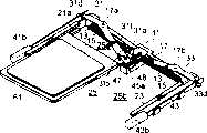
图1是根据本发明一个实施例的卡连接器和将被连接到该卡连接器的两个不同的卡的透视图;1 is a perspective view of a card connector and two different cards to be connected to the card connector according to one embodiment of the present invention;
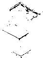
图2是图1所示卡连接器的拆分透视图;Figure 2 is an exploded perspective view of the card connector shown in Figure 1;
图3是图1所示卡连接器的连接机构在其处于初始位置时的放大透视图;Figure 3 is an enlarged perspective view of the connecting mechanism of the card connector shown in Figure 1 when it is in an initial position;
图4是图3所示连接机构的拆分透视图;Fig. 4 is an exploded perspective view of the connecting mechanism shown in Fig. 3;
图5是图3所示连接机构在其处于连接位置时的透视图;Figure 5 is a perspective view of the connecting mechanism shown in Figure 3 in its connected position;
图6是图1中的卡连接器在宽卡插入的初始阶段的透视图;Figure 6 is a perspective view of the card connector in Figure 1 at the initial stage of wide card insertion;
图7是当宽卡容纳在预定的卡位置时与图6类似的透视图;Figure 7 is a perspective view similar to Figure 6 when a wide card is accommodated in a predetermined card position;
图8是图1中的卡连接器在窄卡插入的初始阶段的透视图;Figure 8 is a perspective view of the card connector in Figure 1 at the initial stage of narrow card insertion;
图9是当窄卡容纳在预定的卡位置时与图8类似的透视图。Fig. 9 is a perspective view similar to Fig. 8 when a narrow card is received in a predetermined card position.
具体实施方式Detailed ways
参考图1和图2,下面描述根据本发明实施例的卡连接器。Referring to FIGS. 1 and 2, a card connector according to an embodiment of the present invention will be described below.
图中示出的卡连接器用于连接用在电子设备中的IC卡。通过卡连接器的使用,可以有选择地将宽IC卡(以下称为第一卡51)和窄IC卡(以下称为第二卡61)连接起来。由此,卡连接器能够仅连接一个卡,所述一个卡可以是第一卡51或第二卡61,并且能够同时连接两个第二卡61。在本说明书中,第一卡51和第二卡61可以共同和简单地被称为卡。The card connector shown in the figure is used to connect an IC card used in electronic equipment. By using a card connector, a wide IC card (hereinafter referred to as a first card 51) and a narrow IC card (hereinafter referred to as a second card 61) can be selectively connected. Thereby, the card connector can connect only one card, which may be the
所述卡连接器包括限定部件,即,大体U形的绝缘体11,该限定部件限定用于插入卡的插入区域;固定到绝缘体11上的多个导电接触件13;和用于从插入区域弹出卡的弹出机构。卡沿插入方向A插入并且沿与插入方向A相反的弹出方向B被弹出。正交于插入和弹出方向的方向将被称为宽度方向W。正交于插入方向A和宽度方向W的方向将被称为厚度方向。Described card connector comprises limiting part, namely, generally U-shaped
绝缘体11具有设置有接触件13的连接器部分15,包括连接器部分15的桥接部分17,和一对框架部分21和23,所述一对框架部分21和23分别具有沿宽度方向W与桥接部分17的相对端相连的一端。框架部分21和23沿宽度方向W彼此面对。The
框架部分21和23设置有分别形成在它们的面对的表面上的一对导引凹槽21a和23a。第一卡51插入导引凹槽21a和23a内。尤其是,第一卡51具有垂直于宽度方向W的相对侧面51a和51b。侧面51a和51b分别插入到导引凹槽21a和23a内。第一卡51由导引凹槽21a和23a导引。The
可替换地,第二卡61插入到导引凹槽21a或23a内。第二卡61具有垂直于宽度方向W的相对侧面61a和61b。侧面61a和61b其中之一插入到导引凹槽21a或23a内。第二卡61由导引凹槽21a或23a导引。Alternatively, the
第一卡51设置有与接触件13一一对应接触的多个匹配接触件53。匹配接触件53在插入方向A上的第一卡51的前端处形成在第一卡51的背面上。类似地,第二卡61设置有与接触件13一一对应接触的多个匹配接触件63。匹配接触件63在插入方向A上的第二卡61的前端处形成在第二卡61的背面上。The
在接触部分15内,接触件13沿宽度方向W以预定间隔彼此平行设置。绝缘体11适于容纳沿插入方向A插入到预定卡位置的第一卡51、第二卡61、或两个第二卡61。当第一卡51或第二卡61容纳在预定的卡位置时,匹配接触件53或63与接触器部分15内的接触件13相连。由此,当第一卡51或第二卡61插入到预定的卡位置时,接触件13与匹配接触件53或63相连。In the
弹出机构用于沿与插入方向A相反的弹出方向B移动第一卡51或第二卡61,以便将卡从预定的卡位置弹出。The ejection mechanism is used to move the
另外,下面更详细地描述卡连接器。绝缘体11具有用于容纳第一卡51或第二卡61的容纳部分25。容纳部分25是由绝缘体11,即由包括连接器部分15的桥接部分17,和框架部分21和13围绕的部分。Additionally, the card connector is described in more detail below. The
容纳部分25容纳第一卡51,该第一卡51在宽度方向W上具有与容纳部分25的整个宽度相对应的尺寸。The
另外,容纳部分25具有两个预定区段25a和25b,两个预定区段25a和25b通过分割容纳部分25形成,以便单独容纳第二卡61或两个平行的第二卡61。In addition, the
弹出机构包括一对弹出部件或弹出板31和33,和分别与弹出板31和33接合的一对弹出杆41和43。当弹出机构在第一卡51被插入的情况下操作时,弹出板31和33其中至少之一在插入方向A上与第一卡51的前端面51c接触。当第二卡61被插入时,弹出板31和33其中之一在插入方向A上与第二卡61的前端面61c接触。当插入两个第二卡61时,弹出板31和33与第二卡61的前端面61c一一对应接触。弹出板31和33分别由弹出杆41和43旋转。The eject mechanism includes a pair of eject members or eject
弹出板31和33一一对应地位于预定区段25a和25b,以便沿弹出方向B移动两个第二卡61。The
弹出板31具有在其一端的连接部分31a,与第一卡51或第二卡61接触的挤压部分31b,沿长度方向形成在中间部分处的轴孔31c,和形成在其另一端的板接合部分31d。类似地,弹出板33具有在其一端的连接部分33a,与第一卡51或第二卡61接触的挤压部分33b,沿长度方向形成在中间部分处的轴孔33c,和形成在其另一端的板接合部分33d。The
挤压部分31b和33b分别位于连接部分31a和33a的附近。当第一卡51或第二卡61插入到容纳部分25内的深度从而达到预定的卡位置时,挤压部分31b和33b分别与第一卡51或第二卡61的前端面51c或61c接触。挤压部分31b和33b中的每一个都是通过朝着容纳部分25,即向下,折弯弹出板31和33中的每一个的一部分而形成。The
绝缘体11的桥接部分17设有形成在其上表面上的一对轴部分17a和17b,用于分别可旋转地支撑弹出板31和33。轴部分17a和17b分别配合到弹出板31和33的轴孔31c和33c内,从而弹出板31和33分别绕轴部分17a和17b可旋转。由此,轴部分17a和17b可枢转地支撑弹出板31和33,从而弹出板31和33在容纳部分25之上的正常位置和与预定卡位置对应的预定板位置之间可旋转。The
弹出板31和33的连接部分31a和33a通常彼此重叠并且可沿插入方向A和弹出方向B在容纳部分25之上的正常位置和预定板位置之间沿中心线C移动,所述中心线C沿宽度方向W将容纳部分25分成预定区段25a和25b。The
连接部分31a和33a分别设有连接孔31f和33f。连接孔31f和33f中的每一个具有容纳弹出板31和33的旋转与容纳部分25的中心线C相交的路径的长尺寸。The
弹出杆41和43分别位于框架部分21和23的外部,并且沿框架部分21和23延伸。弹出杆41和43可以分别在插入方向A和弹出方向B上沿框架部分21和23移动。弹出杆41和43分别被形成在框架部分21和23的外表面上的多个支撑部分11g支撑。The eject levers 41 and 43 are located outside the
弹出杆41和43具有形成在它们沿插入方向A的前端处的杆接合孔41a和43a。杆接合孔41a和43a分别容纳弹出板31和33的板接合部分31d和33d以便与它们接合。弹出杆41和43分别具有固定到它们沿弹出方向B的前端处的弹出钮41b和43b。The eject levers 41 and 43 have
绝缘体1设有位于预定区段25a和25b之间的连接机构,所述连接机构沿弹出方向B从桥接部分17延伸至容纳部分25。The insulator 1 is provided with a connection mechanism between the
如放大比例的图3和4所示,连接机构包括连接部件45;滑动器容纳部件47,该滑动器容纳部件47允许连接部件45沿插入方向A和弹出方向B滑动,同时沿垂直方向移动;和滑动器部件49,滑动器部件49具有大体矩形主体并且可沿插入方向A和弹出方向B移动。As shown in FIGS. 3 and 4 on an enlarged scale, the connecting mechanism includes a connecting
当第一卡51插入时,连接部件45与第一卡51的前端面51c接触。当连接部分31a和33a移动到与预定卡位置相应的预定连接位置时,连接部分45将弹出板31和33的连接部分31a和33a彼此连接。When the
在第一卡51或第二卡61没有容纳在容纳部分25内的初始位置处,连接部件45位于连接部分31a和33a之下。连接部件45具有连接销45a,用于当连接部件45在预定连接位置升高时与连接孔31f和33f接合;和销保持部分45b,该销保持部分45b具有矩形主体并且支撑从其竖立起来的连接销45a。In an initial position where the
销保持部分45b设有沿宽度方向W突出的一对圆柱形突出45c。连接销45a设置在图1中的中心线C上。第二卡61可沿插入方向A和弹出方向B在连接销45a和框架部分21或23之间移动。在初始位置,连接销45a位于连接部分31a和33a之下。在两个第二卡61平行容纳在容纳部分25的预定部分25a和25b内的情况下,连接销45a位于两个第二卡61之间。The
连接销45a可沿插入方向A和弹出方向B在容纳部分25的中心线C上移动。当连接销45a沿插入方向A移动时,连接销45a向上突出。当连接销45a位于初始位置(即下部位置)时,连接销45a不与弹出板31和33干涉。当连接销45a沿插入方向A移动时,连接销45a与弹出板31和33的连接部分31a和33a的连接孔31f和33f接合。The
滑动器容纳部件47与绝缘体11的桥接部分17一体形成。销保持部分45b通过滑动部件49与滑动器容纳部件47连接,滑动部件49可在插入方向A和弹出方向B上沿滑动器容纳部件47滑动且不沿垂直方向移动。因此,只有连接部件45沿垂直方向移动同时沿插入方向A和弹出方向B移动。结果,连接销45a与销保持部分45b一起沿垂直方向移动。The
更具体而言,滑动器容纳部件47具有平行于插入方向A和弹出方向B及垂直方向的一对壁部分47a和47b。在壁部分47a和47b之间配合销保持部分45b和滑动部件49。每个壁部分47a和47b设有导引部分48,导引部分48具有沿弹出方向B降低和沿插入方向A升起的阶梯结构。除了壁部分47a和47b,滑动器容纳部件47还具有封闭壁部分47a和47b之间在弹出方向上的开口的底部分47e和停止壁部分47f。插入方向A上的另一开口由绝缘体11的桥接部分17封闭。在滑动器容纳部件47内,滑动部件49的向下运动由底部分47e限制。在滑动器容纳部件47内,滑动部件49沿弹出方向B和插入方向A的运动由停止壁部分47f和桥接部分17限制。每个导引部分48是形成在每一个壁部分47a和47b内的导引长孔,从而销保持部分45b的突出部分45c被可滑动地接合。销保持部分45b的突出部分45c向上突出并且插入到导引部分48内,以便可沿插入方向A和弹出方向B滑动。导引部分48具有分别在弹出方向B和插入方向A上的弹出端48a和插入端48b。弹出端48a和插入端48b平行于弹出方向B和插入方向A。位于低位的弹出端48a和位于高位的插入端48b通过倾斜的中间部分48c彼此连接。滑动部件49具有容纳销保持部分45b从而销保持部分45b可上下移动的管状部分49a和从滑动部件49的上端面49b向下延伸的一对切口部分49c。切口部分49c容纳突出部分45c以便允许突出部分45c和销保持部分45b的垂直移动。由此,突出部分45c在滑动部件49的切口部分49c内活动。More specifically, the
下面参考图1,6和7描述作为宽卡的第一卡51插入卡连接器的容纳部分25内直到第一卡51容纳在预定卡位置的操作,以及弹出机构和连接机构的操作。1, 6 and 7, the operation of inserting the
为了将第一卡51插入容纳部分25内,在图1中未插入位置(即,第一卡51没有插入容纳部分25内的位置)的第一卡51沿插入方向A插入到容纳部分25内,如图6所示。第一卡51沿框架部分21和23的导引凹槽21a和23a进一步插入,以便与容纳部分25的中心线C上的连接销45a接触。然后,第一卡51的端面51c与弹出板31和33的挤压部分31b和33b接触,以便沿插入方向A挤压弹出板31和33。弹出板31和33绕轴部分17a和17b转动,以便移动到预定板位置。同时,连接销45a被第一卡51的端面51c挤压,以便移动到下面将要描述的预定连接位置。In order to insert the
如图7所示,当弹出板31和33到达预定板位置时,第一卡51的匹配接触件53与接触件13相连。当弹出板31和33旋转时,弹出杆41和43沿弹出方向B移动并且与图6所示的初始位置相比,弹出钮41b和43b沿弹出方向B突出。As shown in FIG. 7 , when the
在连接机构中,销保持部分45b的突出部分45c插入滑动器容纳部件47的导引部分48内。当没有卡插入时,连接销45a位于图3所示的初始位置。当第一卡51被沿插入方向A向前压时,连接销45a和滑动部件49也沿插入方向A移动。随着连接销45a沿插入方向A的移动,突出部分45c沿滑动器容纳部件47的导引部分48滑动。当第一卡51到达预定卡位置时,连接销45a到达图5所示的连接位置,在该连接位置,连接销45a与连接部分31a和33a的连接孔31f和33f接合以便将连接部分31a和33a彼此连接。In the connection mechanism, the protruding
具体而言,随着连接销45a沿插入方向A的移动,销保持部分45b的突出部分45c在导引部分48内从弹出端48a移动到中间部分48c。沿着中间部分48c的倾斜,突出部分45c逐渐在导引部分48和滑动部件49的切口部分49c内向上移动。因此,连接销45a与销保持部分45b一起向上移动。由此,在其沿插入方向A移动时,连接销45a逐渐升起。其后,突出部分45c在导引部分48内向上移动到插入端48b,从而连接销45a与连接孔31f和33f接合,以便将连接部分31a和33a彼此连接。Specifically, as the
在具有上述结构的连接机构中,当连接销45a被沿插入方向A施加力时,连接销45a沿插入方向A向前移动并且被向上移动,因为突出部分45c在导引部分48内向上移动。由于连接销45a被强制仅在滑动部件49的管状部分49a内垂直移动,因此连接销45a能够可靠地操作且不会倾斜。In the connection mechanism having the above structure, when the
为了从容纳部分25内的预定卡位置弹出第一卡51,弹出钮41b和43其中之一被沿插入方向A挤压。在这种情况下,通过连接销45a连接的弹出板31和33的连接部分31a和33a沿弹出方向B旋转,以便从预定连接位置返回到初始位置。同时,连接销45a从图5所示的预定连接位置返回到图3所示的初始位置。连接销45a与连接部分31a和33a一起沿弹出方向B移动并且在初始位置与连接部分31a和33a分离。In order to eject the
由此,第一卡51a容纳在弹出板31和33的连接部分31a和33a通过连接销45a彼此相连的状态下。因此,通过操作彼此连接的弹出杆41和43的弹出钮41b和43b中的任一个,第一卡51能够无故障地弹出并且从容纳部分25内取出。Thus, the
在这种情况下,弹出板31和33的挤压部分31b和33b分别推动第一卡51的两个不同点。因此,弹出力均匀地施加到第一卡51上。这使得第一卡51的弹出平稳。In this case, the
如图1所示,卡连接器通常固定在诸如印刷电路板等板71上。容纳部分25可以在其顶部用盖部件(未示出)覆盖。因此,很难从视觉上确认第一卡51和第二卡61中的哪一个卡容纳在容纳部分25内。As shown in Figure 1, the card connector is typically mounted on a
在卡连接器用盖部件覆盖的情况下,盖部件设置有开口,所述开口至少形成在这样的区域内,在该区域内,连接部分31a和33a通过连接销45a彼此连接。In the case where the card connector is covered with a cover member, the cover member is provided with an opening formed at least in a region in which the
通过开口,连接销45a的端部能够通过连接孔31f和33f观察到。在这种情况下,即,如果连接销45a的端部被看到,那么就确认第一卡51容纳在容纳部分25内而第二卡61没有容纳在容纳部分25内。Through the opening, the ends of the
下面参考图1,8和9描述第二卡61插入到卡连接器的容纳部分25内直到第二卡61容纳在预定位置的操作,以及弹出机构的操作。The operation of inserting the
处于图1所示未插入位置的第二卡61插入在容纳部分25的预定区段25a中。此时,第二卡61沿框架部分21的导引凹槽21a插入。The
当进行第二卡61的插入时,垂直于宽度方向W的第二卡61的一个侧面61b于容纳部分25的中心线C上的连接销45a接触。与所述一个侧面61b相邻的第二卡61的背面在滑动器容纳部件47的一个壁部分47a的上表面上滑动。When insertion of the
第二卡61的端面61c与一个弹出板31的挤压部分31b接触,以便沿插入方向A挤压弹出板31,从而弹出板31绕轴部分17a旋转以便移动到预定板位置。The
在图8和图9中,另一个弹出板33的连接部分33a的端部省略了,以便于理解下面的描述。In FIGS. 8 and 9 , the end portion of the connecting
如图9所示,在第二卡61被沿插入方向A挤压时弹出板31沿插入方向A旋转。当第二卡61到达预定卡位置时,弹出板31也移动到预定板位置。由此,第二卡61容纳在容纳部分25的预定区段25a内。As shown in FIG. 9 , the
当弹出板31旋转到达预定板位置时,第二卡61的匹配接触件63与接触件13连接。当弹出板31旋转时,弹出杆41沿弹出方向B移动,从而与图8所示的初始位置相比,弹出钮41b沿弹出方向B突出。When the
为了将第二卡61从容纳部分25内的预定卡位置弹出,弹出钮41b被沿插入方向A挤压,以便沿弹出方向B旋转弹出板31的连接部分31a。当弹出板31从预定板位置返回到初始位置时,第二卡61被弹出。To eject the
由此,通过沿插入方向A挤压弹出杆41的弹出钮41b,弹出板31沿弹出方向B朝着容纳部分25旋转,从而第二卡61的端面61c被挤压部分31b挤压。然后,容纳在容纳部分25内的第二卡61沿弹出方向B移动。Thus, by pressing the
上述说明也适用于第二卡61插入到容纳部分25的预定部分25b内的情况。由于弹出板31和33中的每一个都单独和独立地如上操作,因此容纳在预定区段25a和25b中任一个内的第二卡61都能够通过操作弹出钮41b和43b中的相应的一个而被弹出。The above description also applies to the case where the
在两个第二卡61插入容纳部分25的预定区段25a和25b内的情况下,弹出板31和33不相互连接。因此,弹出板31和33能够彼此独立地操作。In a state where the two
导引部分48中的每一个都可以为形成在壁部分47a和47b的面对的表面中每一个上的肋部分,从而销保持部分45b的突出部分45c可以可滑动地接合。导引部分48可以为形成在壁部分47a和47b的面对的表面中每一个上的长槽。Each of the
连接机构可以具有除上述结构以外的任何其他合适的结构,只要连接销45a的向上移动是随着沿插入方向A的移动实现的。The connection mechanism may have any other suitable structure than the above-mentioned structure, as long as the upward movement of the
根据本发明的卡连接器至少具有一对彼此独立的弹出机构。当第二卡插入时,弹出机构可彼此独立地操作。当第一卡插入时,弹出机构通过连接机构彼此相关联地操作。由此,可以可靠地弹出第一卡和第二卡中或者多个卡中所需的一个。The card connector according to the present invention has at least one pair of ejection mechanisms independent of each other. When the second card is inserted, the ejection mechanisms are operable independently of each other. When the first card is inserted, the ejection mechanisms operate in association with each other through the connection mechanism. Thereby, a desired one of the first card and the second card or a plurality of cards can be reliably ejected.
通过给连接机构提供用于识别第一卡(宽卡)和第二卡(窄卡)的机构,可以防止卡被误弹出。By providing the connection mechanism with a mechanism for identifying the first card (wide card) and the second card (narrow card), it is possible to prevent cards from being accidentally ejected.
根据本发明的卡连接器不但适用于IC卡连接器也适用于装入诸如使用了SD卡、存储卡、或PC卡的笔记本个人计算机等各种电子设备和诸如PDA和移动电话等移动终端内的卡连接器。The card connector according to the present invention is suitable not only for an IC card connector but also for being incorporated into various electronic devices such as notebook personal computers using SD cards, memory cards, or PC cards, and mobile terminals such as PDAs and mobile phones. card connector.
上面结合优选实施例描述了本发明,对于本领域的普通技术人员而言,在不脱离本发明权利要求限定的范围内,可以以多种其他方式实施本发明。The present invention has been described above in conjunction with the preferred embodiments. For those skilled in the art, the present invention can be implemented in various other ways without departing from the scope defined by the claims of the present invention.
Claims (16)
Applications Claiming Priority (2)
| Application Number | Priority Date | Filing Date | Title |
|---|---|---|---|
| JP2003421816AJP3929052B2 (en) | 2003-12-19 | 2003-12-19 | Card connector |
| JP2003421816 | 2003-12-19 |
Publications (2)
| Publication Number | Publication Date |
|---|---|
| CN1630141Atrue CN1630141A (en) | 2005-06-22 |
| CN1324767C CN1324767C (en) | 2007-07-04 |
Family
ID=34675285
Family Applications (1)
| Application Number | Title | Priority Date | Filing Date |
|---|---|---|---|
| CNB2004101049651AExpired - Fee RelatedCN1324767C (en) | 2003-12-19 | 2004-12-15 | Card connector having an eject mechanism adaptable to a plurality of kinds of cards different in size |
Country Status (4)
| Country | Link |
|---|---|
| US (1) | US6991480B2 (en) |
| JP (1) | JP3929052B2 (en) |
| CN (1) | CN1324767C (en) |
| TW (1) | TWI248710B (en) |
Cited By (7)
| Publication number | Priority date | Publication date | Assignee | Title |
|---|---|---|---|---|
| CN101911091A (en)* | 2007-10-26 | 2010-12-08 | 莫列斯公司 | Card connector for receiving multiple cards |
| CN102623840A (en)* | 2011-01-26 | 2012-08-01 | 鸿富锦精密工业(深圳)有限公司 | Card seat mechanism and electronic device adopting the card seat mechanism |
| CN102938994A (en)* | 2011-08-15 | 2013-02-20 | 富泰华工业(深圳)有限公司 | Portable electronic device and chip card fixture mechanism thereof |
| CN105024194A (en)* | 2015-08-17 | 2015-11-04 | 广东欧珀移动通信有限公司 | Card seat structure and mobile terminal thereof |
| CN107634389A (en)* | 2017-08-14 | 2018-01-26 | 启东乾朔电子有限公司 | Electronic card connector and card tray |
| WO2019105271A1 (en)* | 2017-11-29 | 2019-06-06 | xin信息技术有限公司 | Insertion and extraction apparatus for card and electronic device |
| CN110880649A (en)* | 2019-09-25 | 2020-03-13 | 深圳传音控股股份有限公司 | Card holder assembly, card connector and terminal |
Families Citing this family (33)
| Publication number | Priority date | Publication date | Assignee | Title |
|---|---|---|---|---|
| JP3774895B1 (en)* | 2005-02-17 | 2006-05-17 | 日本航空電子工業株式会社 | Card connector |
| CN1870446A (en)* | 2005-05-28 | 2006-11-29 | 深圳富泰宏精密工业有限公司 | Locking structure of SIM card |
| TWI287898B (en)* | 2006-04-06 | 2007-10-01 | Benq Corp | Electronic device and an ejection device |
| US7561416B1 (en)* | 2006-12-15 | 2009-07-14 | Western Digital Technologies, Inc. | Storage device fixture with simultaneous unload mechanism |
| EP2141493A4 (en)* | 2007-03-28 | 2015-03-11 | Arkray Inc | ANALYZER |
| TWI358173B (en)* | 2007-04-30 | 2012-02-11 | Hon Hai Prec Ind Co Ltd | Card connector and assembly of the same |
| TWI358165B (en)* | 2007-04-30 | 2012-02-11 | Hon Hai Prec Ind Co Ltd | Electrical card connector |
| TWI368358B (en)* | 2007-06-11 | 2012-07-11 | Hon Hai Prec Ind Co Ltd | Electrical card connector |
| US7804683B2 (en)* | 2007-06-21 | 2010-09-28 | Nokia Corporation | Electronic device component eject mechanism |
| US7612993B1 (en)* | 2008-07-15 | 2009-11-03 | Ddk Ltd. | Card connector |
| TWI372967B (en)* | 2010-03-15 | 2012-09-21 | Wistron Corp | Unloading mechanism for unloading an electronic component and computer device thereof |
| US8154862B2 (en)* | 2010-08-30 | 2012-04-10 | Ping-Hung Lai | Open external hard drive enclosure |
| CN102480892B (en)* | 2010-11-30 | 2014-10-08 | 富泰华工业(深圳)有限公司 | Chip card fixing mechanism and portable electronic device with fixing mechanism |
| TW201232928A (en)* | 2011-01-17 | 2012-08-01 | Walton Advanced Eng Inc | Data storage device |
| US9064200B2 (en)* | 2011-01-31 | 2015-06-23 | Apple Inc. | Flat object ejector assembly |
| US8369080B2 (en)* | 2011-02-25 | 2013-02-05 | Jui-Shu Huang | Removable hard disk drive bay |
| CN102957040A (en)* | 2011-08-19 | 2013-03-06 | 富泰华工业(深圳)有限公司 | Portable electronic device and chip card fixing mechanism thereof |
| CN103050835B (en)* | 2011-10-17 | 2015-03-25 | 富泰华工业(深圳)有限公司 | Portable electronic device and chip card holding mechanism |
| CN103326182B (en)* | 2012-03-23 | 2016-12-14 | 富泰华工业(深圳)有限公司 | Chip card locking mechanism and apply the electronic installation of this chip card locking mechanism |
| CN103531958B (en)* | 2012-07-06 | 2016-06-29 | 罗普特(厦门)科技集团有限公司 | Electronic installation |
| CN103887650A (en)* | 2012-12-20 | 2014-06-25 | 深圳富泰宏精密工业有限公司 | Chip holding structure and electronic device having chip holding structure |
| CN103887653A (en)* | 2012-12-22 | 2014-06-25 | 富泰华工业(深圳)有限公司 | Electronic device |
| CN104241925A (en)* | 2013-06-11 | 2014-12-24 | 深圳富泰宏精密工业有限公司 | Chip card installing and taking structure |
| US9076025B2 (en)* | 2013-06-12 | 2015-07-07 | Cheng Uei Precision Industry Co., Ltd. | Card connector |
| KR20150108217A (en)* | 2014-03-17 | 2015-09-25 | 몰렉스 엘엘씨 | Puller type CARD SOCKET |
| US9246249B2 (en)* | 2014-05-14 | 2016-01-26 | Proconn Technology Co., Ltd. | Card connector for different specifications of electronic cards |
| KR101586252B1 (en)* | 2014-08-08 | 2016-01-20 | (주)우주일렉트로닉스 | Connector System with Multi Receiving Part |
| CN106299838A (en)* | 2015-06-05 | 2017-01-04 | 富士康(昆山)电脑接插件有限公司 | Electronic card coupler |
| CN106299926A (en)* | 2015-06-05 | 2017-01-04 | 富士康(昆山)电脑接插件有限公司 | Electronic card coupler |
| CN107230853B (en)* | 2016-03-25 | 2019-06-18 | 深圳富泰宏精密工业有限公司 | Chip card clamping component and electronic device |
| TWI719603B (en)* | 2019-08-23 | 2021-02-21 | 緯創資通股份有限公司 | Connecting module and electronic device |
| CN114390814B (en)* | 2020-10-20 | 2024-10-01 | 纬联电子科技(中山)有限公司 | Card taking mechanism and expansion assembly comprising same |
| KR20230012234A (en) | 2021-07-15 | 2023-01-26 | 삼성전자주식회사 | Electronic device including tray |
Family Cites Families (9)
| Publication number | Priority date | Publication date | Assignee | Title |
|---|---|---|---|---|
| US5836775A (en)* | 1993-05-13 | 1998-11-17 | Berg Tehnology, Inc. | Connector apparatus |
| JP2789017B2 (en) | 1993-12-24 | 1998-08-20 | 株式会社ピーエフユー | Eject device for card media |
| US5655918A (en)* | 1996-02-29 | 1997-08-12 | Berg Technology, Inc. | Selectable ejector for a double-deck PCMCIA eject header |
| US5907354A (en)* | 1996-05-23 | 1999-05-25 | Eastman Kodak Company | Memory card housing with a center-actuated ejector |
| JP3556090B2 (en)* | 1998-05-01 | 2004-08-18 | アルプス電気株式会社 | Connector device for IC card |
| JP3948938B2 (en)* | 2001-11-13 | 2007-07-25 | アルプス電気株式会社 | Card connector device |
| US6482030B1 (en)* | 2001-12-18 | 2002-11-19 | Hon Hai Precision Ind. Co., Ltd. | Stacked electronic card connector assembly |
| TW520094U (en)* | 2001-12-19 | 2003-02-01 | I O Interconnect Inc | Memory card connecting seat assembly and its detection device |
| JP3827582B2 (en) | 2002-02-01 | 2006-09-27 | アルプス電気株式会社 | Card connector device |
- 2003
- 2003-12-19JPJP2003421816Apatent/JP3929052B2/ennot_activeExpired - Fee Related
- 2004
- 2004-12-15USUS11/012,563patent/US6991480B2/ennot_activeExpired - Fee Related
- 2004-12-15CNCNB2004101049651Apatent/CN1324767C/ennot_activeExpired - Fee Related
- 2004-12-16TWTW093139079Apatent/TWI248710B/ennot_activeIP Right Cessation
Cited By (10)
| Publication number | Priority date | Publication date | Assignee | Title |
|---|---|---|---|---|
| CN101911091A (en)* | 2007-10-26 | 2010-12-08 | 莫列斯公司 | Card connector for receiving multiple cards |
| CN102623840A (en)* | 2011-01-26 | 2012-08-01 | 鸿富锦精密工业(深圳)有限公司 | Card seat mechanism and electronic device adopting the card seat mechanism |
| CN102623840B (en)* | 2011-01-26 | 2014-08-20 | 鸿富锦精密工业(深圳)有限公司 | Card holder mechanism and electronic device with card holder mechanism |
| CN102938994A (en)* | 2011-08-15 | 2013-02-20 | 富泰华工业(深圳)有限公司 | Portable electronic device and chip card fixture mechanism thereof |
| CN105024194A (en)* | 2015-08-17 | 2015-11-04 | 广东欧珀移动通信有限公司 | Card seat structure and mobile terminal thereof |
| CN107634389A (en)* | 2017-08-14 | 2018-01-26 | 启东乾朔电子有限公司 | Electronic card connector and card tray |
| CN107634389B (en)* | 2017-08-14 | 2023-01-17 | 启东乾朔电子有限公司 | Electronic card connector and card tray |
| WO2019105271A1 (en)* | 2017-11-29 | 2019-06-06 | xin信息技术有限公司 | Insertion and extraction apparatus for card and electronic device |
| CN110880649A (en)* | 2019-09-25 | 2020-03-13 | 深圳传音控股股份有限公司 | Card holder assembly, card connector and terminal |
| CN115699464A (en)* | 2019-09-25 | 2023-02-03 | 深圳传音控股股份有限公司 | Card Tray Assemblies, Card Connectors and Terminals |
Also Published As
| Publication number | Publication date |
|---|---|
| JP2005183155A (en) | 2005-07-07 |
| CN1324767C (en) | 2007-07-04 |
| JP3929052B2 (en) | 2007-06-13 |
| US20050136712A1 (en) | 2005-06-23 |
| US6991480B2 (en) | 2006-01-31 |
| TW200525830A (en) | 2005-08-01 |
| TWI248710B (en) | 2006-02-01 |
Similar Documents
| Publication | Publication Date | Title |
|---|---|---|
| CN1324767C (en) | Card connector having an eject mechanism adaptable to a plurality of kinds of cards different in size | |
| US6814596B2 (en) | Card connector having low profile and vision indicator | |
| CN102651505B (en) | Connector | |
| US7976327B2 (en) | Card connector for receiving multiple cards | |
| CN1149162A (en) | Integrated circuit card information processing device | |
| JP2004086859A (en) | General-purpose slot into which many kinds of flash memory cards can be inserted | |
| KR100404629B1 (en) | Card connector | |
| US7494357B2 (en) | Socket with latching equipment | |
| CN1716153A (en) | Port replicator | |
| CN1835301A (en) | Card connector adapted for cards having different width dimensions | |
| CN1941511A (en) | Card connector device | |
| US7040908B2 (en) | Card connector which can be connected to a plurality of kinds of cards different in width | |
| CN111697399A (en) | Multi-card socket for mobile communication terminal and multi-card connector including the same | |
| CN1848549A (en) | IC package, IC socket, and IC socket assembly | |
| JP2006012828A (en) | Card connector | |
| US7300295B2 (en) | Connector which can be reduced in operating force and miniaturized | |
| US6811421B1 (en) | Socket connector with pivoting operating members | |
| US7255594B2 (en) | Connector for flexible printed circuit board | |
| CN111834812A (en) | Connector Brackets and Connectors | |
| US20220140510A1 (en) | Card retaining member and card connector set | |
| US7658634B2 (en) | Zero insertion force connector with an improved driver member | |
| CN212968138U (en) | Ejection assembly and terminal equipment | |
| CN108068464B (en) | Ink cartridge | |
| CN1976136A (en) | Card connector | |
| JP2003297489A (en) | Memory card connector |
Legal Events
| Date | Code | Title | Description |
|---|---|---|---|
| C06 | Publication | ||
| PB01 | Publication | ||
| C10 | Entry into substantive examination | ||
| SE01 | Entry into force of request for substantive examination | ||
| C14 | Grant of patent or utility model | ||
| GR01 | Patent grant | ||
| ASS | Succession or assignment of patent right | Owner name:JAPAN AIRLINES ELECTRONIC INDUSTRY CO., LTD. Free format text:FORMER OWNER: JAPAN AIRLINES ELECTRONIC INDUSTRY CO., LTD.; HIROSAKI AVIONICS CO., LTD. Effective date:20081031 | |
| C41 | Transfer of patent application or patent right or utility model | ||
| TR01 | Transfer of patent right | Effective date of registration:20081031 Address after:Tokyo, Japan Patentee after:Japan Aviation Electronics Industry Co., Ltd. Address before:Tokyo, Japan Co-patentee before:Honda Giken Kogyo Kabushiki kaisha Co., Ltd. Patentee before:Japan aeronautical electronics Industry Corporation | |
| CF01 | Termination of patent right due to non-payment of annual fee | Granted publication date:20070704 Termination date:20191215 | |
| CF01 | Termination of patent right due to non-payment of annual fee |