CN1627926A - Dedicated maintenance system with dedicated maintenance unit and cooling unit - Google Patents
Dedicated maintenance system with dedicated maintenance unit and cooling unitDownload PDFInfo
- Publication number
- CN1627926A CN1627926ACN03803338.0ACN03803338ACN1627926ACN 1627926 ACN1627926 ACN 1627926ACN 03803338 ACN03803338 ACN 03803338ACN 1627926 ACN1627926 ACN 1627926A
- Authority
- CN
- China
- Prior art keywords
- shaped
- depression
- groove
- cooling device
- housing
- Prior art date
- Legal status (The legal status is an assumption and is not a legal conclusion. Google has not performed a legal analysis and makes no representation as to the accuracy of the status listed.)
- Granted
Links
Images

Classifications
- A—HUMAN NECESSITIES
- A61—MEDICAL OR VETERINARY SCIENCE; HYGIENE
- A61F—FILTERS IMPLANTABLE INTO BLOOD VESSELS; PROSTHESES; DEVICES PROVIDING PATENCY TO, OR PREVENTING COLLAPSING OF, TUBULAR STRUCTURES OF THE BODY, e.g. STENTS; ORTHOPAEDIC, NURSING OR CONTRACEPTIVE DEVICES; FOMENTATION; TREATMENT OR PROTECTION OF EYES OR EARS; BANDAGES, DRESSINGS OR ABSORBENT PADS; FIRST-AID KITS
- A61F7/00—Heating or cooling appliances for medical or therapeutic treatment of the human body
- A61F7/10—Cooling bags, e.g. ice-bags
- A—HUMAN NECESSITIES
- A45—HAND OR TRAVELLING ARTICLES
- A45D—HAIRDRESSING OR SHAVING EQUIPMENT; EQUIPMENT FOR COSMETICS OR COSMETIC TREATMENTS, e.g. FOR MANICURING OR PEDICURING
- A45D26/00—Hair-singeing apparatus; Apparatus for removing superfluous hair, e.g. tweezers
- A45D26/0061—Hair-singeing apparatus; Apparatus for removing superfluous hair, e.g. tweezers with means for reducing pain during hair removal
- A—HUMAN NECESSITIES
- A61—MEDICAL OR VETERINARY SCIENCE; HYGIENE
- A61F—FILTERS IMPLANTABLE INTO BLOOD VESSELS; PROSTHESES; DEVICES PROVIDING PATENCY TO, OR PREVENTING COLLAPSING OF, TUBULAR STRUCTURES OF THE BODY, e.g. STENTS; ORTHOPAEDIC, NURSING OR CONTRACEPTIVE DEVICES; FOMENTATION; TREATMENT OR PROTECTION OF EYES OR EARS; BANDAGES, DRESSINGS OR ABSORBENT PADS; FIRST-AID KITS
- A61F7/00—Heating or cooling appliances for medical or therapeutic treatment of the human body
- A61F2007/0001—Body part
- F—MECHANICAL ENGINEERING; LIGHTING; HEATING; WEAPONS; BLASTING
- F25—REFRIGERATION OR COOLING; COMBINED HEATING AND REFRIGERATION SYSTEMS; HEAT PUMP SYSTEMS; MANUFACTURE OR STORAGE OF ICE; LIQUEFACTION SOLIDIFICATION OF GASES
- F25D—REFRIGERATORS; COLD ROOMS; ICE-BOXES; COOLING OR FREEZING APPARATUS NOT OTHERWISE PROVIDED FOR
- F25D2303/00—Details of devices using other cold materials; Details of devices using cold-storage bodies
- F25D2303/08—Devices using cold storage material, i.e. ice or other freezable liquid
- F25D2303/082—Devices using cold storage material, i.e. ice or other freezable liquid disposed in a cold storage element not forming part of a container for products to be cooled, e.g. ice pack or gel accumulator
- F25D2303/0822—Details of the element
- F25D2303/08222—Shape of the element
- F—MECHANICAL ENGINEERING; LIGHTING; HEATING; WEAPONS; BLASTING
- F25—REFRIGERATION OR COOLING; COMBINED HEATING AND REFRIGERATION SYSTEMS; HEAT PUMP SYSTEMS; MANUFACTURE OR STORAGE OF ICE; LIQUEFACTION SOLIDIFICATION OF GASES
- F25D—REFRIGERATORS; COLD ROOMS; ICE-BOXES; COOLING OR FREEZING APPARATUS NOT OTHERWISE PROVIDED FOR
- F25D3/00—Devices using other cold materials; Devices using cold-storage bodies
- F25D3/02—Devices using other cold materials; Devices using cold-storage bodies using ice, e.g. ice-boxes
- F25D3/06—Movable containers
- F25D3/08—Movable containers portable, i.e. adapted to be carried personally
Landscapes
- Health & Medical Sciences (AREA)
- General Health & Medical Sciences (AREA)
- Pain & Pain Management (AREA)
- Physics & Mathematics (AREA)
- Thermal Sciences (AREA)
- Engineering & Computer Science (AREA)
- Biomedical Technology (AREA)
- Heart & Thoracic Surgery (AREA)
- Vascular Medicine (AREA)
- Life Sciences & Earth Sciences (AREA)
- Animal Behavior & Ethology (AREA)
- Public Health (AREA)
- Veterinary Medicine (AREA)
- Thermotherapy And Cooling Therapy Devices (AREA)
- Dry Shavers And Clippers (AREA)
- Dental Tools And Instruments Or Auxiliary Dental Instruments (AREA)
Abstract
Description
Translated fromChinese本发明涉及一种具有专用保养装置和冷却装置的专用保养系统,该冷却装置具有一个塑料壳体,其内含有冷却剂,并且具有导热装置。The invention relates to a special maintenance system with a special maintenance device and a cooling device. The cooling device has a plastic shell containing coolant and has a heat conduction device.
本发明还涉及一种专用保养系统用的冷却装置,该冷却装置有一塑料壳体,其内含有冷却剂,并且具有导热装置。The invention also relates to a cooling device for a special maintenance system, the cooling device has a plastic shell containing coolant and a heat conduction device.
相当于上面所说专用保养系统的一种毛发去除系统和这个系统使用的冷却装置曾在专利文件WO 00/76363 A1中公开过。在这已知的实施方案中,铝制的导热装置具有三个部分:第一部分被容纳在冷却装置的壳体内并可导走热地与冷却剂接触;第二部分连在第一部分上,被设计成基本如套筒的形式而具有椭圆的外形;第二部分的一端被一套筒底即第三部分封闭,其目的是要用来冷却人体上要被冷却的区域。在该已知的设计中,套筒形式的第二部分在其套筒的外壁面上设有多个自身闭合成环状的槽状凹陷,用来接纳在壳体上用注射模塑法制成的、自身也是闭合成环状的带状突起。在该例中,槽状凹陷的横截面成U字形,当从朝向凹陷底壁的方向看去时第一个凹陷的两个侧壁都各略微向内倾斜。由于导热装置第二部分采用套筒形式,因此具有足够高的弹性,尽管在这种冷却装置内会发生温度差,仍能在塑料的壳体和铝制导热装置的第二部分之间保持良好的密封,从而可防止壳体内所含冷却剂的不希望有的逸出。A kind of hair removal system equivalent to the above-mentioned special maintenance system and the cooling device used by this system were once disclosed in the patent document WO 00/76363 A1. In this known embodiment, the heat-conducting device made of aluminum has three parts: a first part is accommodated in the housing of the cooling device and is in contact with the coolant in a heat-dissipating manner; a second part is connected to the first part and is Designed substantially in the form of a sleeve with an oval shape; the second part is closed at one end by a sleeve bottom, the third part, which is intended to cool the area of the body to be cooled. In this known design, the second part in the form of a sleeve is provided on the outer wall of the sleeve with a plurality of groove-like recesses which close themselves into a ring for receiving on the housing by injection moulding. It is also a band-shaped protrusion that is closed into a ring. In this example, the cross-section of the groove-shaped depression is U-shaped, and both side walls of the first depression are slightly inclined inwardly when viewed from the direction towards the bottom wall of the depression. Due to the sleeve-like form of the second part of the heat transfer device, it is sufficiently elastic to maintain a good hold between the plastic housing and the second part of the heat transfer device made of aluminum, despite the temperature differences that occur in such cooling devices The seal prevents unwanted escape of the coolant contained in the housing.
实际调查曾经表明,在导热装置的具有不同外形设计的第二部分通过壳体的地方采用专利WO 00/76363A1的方案遗憾地并不能满足要求。这是因为当导热装置的第二部分由金属制成,而且例如多少具有板状的外形,并被塑料的壳体包围时,由于这两种材料的热膨胀系数有相当大的差别,所以不希望有的泄漏仍会发生。Practical investigations have shown that the solution of patent WO 00/76363 A1, where the second part of the heat conduction device having a different external design passes through the housing, unfortunately does not meet the requirements. This is because when the second part of the heat-conducting device is made of metal, and for example has a somewhat plate-like shape and is surrounded by a plastic housing, it is not desirable to Some leaks still happen.
本发明为自身设定的目的就是要克服上面列出的困难而提供一种改进的专用保养系统和改进的冷却装置。The object which the present invention has set itself is to provide an improved dedicated maintenance system and an improved cooling device overcoming the above-listed difficulties.
为了达到上述目的,按照本发明的专用保养系统具有下列特征:In order to achieve the above object, the special maintenance system according to the present invention has the following characteristics:
一种具有专用保养装置和冷却装置的专用保养系统,该冷却装置具有一个塑料壳体,其内含有冷却剂,并且具有导热装置。其中导热装置有一被容纳在冷却装置壳体内并与该冷却剂或导热连接的第一部分,沿通道的方向通过壳体的第二部分,以及旨在冷却人体上要被冷却区域的第三部分。其中在导热装置的第二部分和包围在其外面的壳体区域之间设有至少一个沿通道的横向延伸的、由至少一个槽状凹陷和至少一个带状突起构成的组合,并且其中在该至少一个组合中的至少一个槽状凹陷是由两个侧壁限定的,而其中至少一个侧壁的形状能被带状突起的一部分在其后面钩住。A special maintenance system has a special maintenance device and a cooling device, the cooling device has a plastic shell containing coolant and has a heat conduction device. Wherein the heat conduction device has a first part which is accommodated in the housing of the cooling device and connected with the coolant or heat conduction, a second part passing through the housing in the direction of the channel, and a third part intended to cool the area to be cooled on the human body. Wherein at least one combination of at least one groove-shaped depression and at least one strip-shaped protrusion extending transversely along the channel is provided between the second part of the heat conducting device and the housing area surrounding it, and wherein the At least one trough-like depression in at least one combination is defined by two side walls, and at least one of the side walls is shaped to be hooked behind it by a portion of the strip-like protrusion.
为了达到上述目的,按照本发明的冷却装置具有下列特征:In order to achieve the above object, the cooling device according to the present invention has the following features:
一种专用保养系统用的冷却装置,该冷却装置有一塑料壳体,其内含有冷却剂,并且具有导热装置。其中导热装置有一被容纳在冷却装置壳体内并与冷却剂连接成导热的第一部分,一个沿通道方向通过该壳体的第二部分,以及旨沿冷却人体上要被冷却区域的第三部分。其中在导热装置的第二部分和包围在其外面的壳体之间设有至少一个沿通道的横向延伸的由至少一个槽状凹陷和至少一个带状突起构成的组合,并且其中在该至少一个组合中的至少一个槽状凹陷是由两个侧壁限定的,而其中至少一个侧壁的形状能被带状突起的一部分在其后面钩住。A cooling device for a special maintenance system, the cooling device has a plastic shell, which contains coolant, and has a heat conduction device. Wherein the heat conduction device has a first part which is accommodated in the housing of the cooling device and connected with the coolant for heat conduction, a second part which passes through the housing along the channel direction, and a third part which is intended to cool the area to be cooled on the human body. Wherein at least one combination of at least one groove-shaped depression and at least one band-shaped protrusion extending along the transverse direction of the channel is provided between the second part of the heat conducting device and the casing surrounding it, and wherein the at least one At least one trough-like depression in the combination is defined by two side walls, and at least one of the side walls is shaped to be hooked behind it by a portion of the band-like protrusion.
由于具有按照本发明的上述这些特征,便能以结构简单、容易制造的方式作出有效的设计,使当按照本发明的冷却装置暴露在高温差的环境之下时始终能够在导热装置延伸通过冷却装置壳体的区域内保持令人满意的密封。这可从两方面进行分析。首先当冷却装置变冷时,如同将它放置在冰箱的冷冻间内或放置在冷冻柜内的情况,这时冷却装置的塑料壳体和金属导热装置的第二部分都将收缩,但前者的收缩程度比后者大,于是带状突起的每一个在后面钩住凹陷侧壁的部分将从后面以较高的力抵压在它所钩住的凹陷侧壁上,从而可得到安全可靠的密封。其次,当冷却装置变暖时,如同专用保养系统和冷却装置在使用时的情况,这时冷却装置的塑料壳体的膨胀程度将比金属的导热装置的第二部分大,这时塑料壳体的每一个带状突起将以较高的力抵压在槽状凹陷的底壁上,还抵压在从一个槽状凹陷到相邻槽状凹陷之间的过渡区域上,这样也可得到令人满意的密封。Owing to have according to above-mentioned these features of the present invention, just can make effective design in the mode of simple structure, easy manufacture, make when the cooling device according to the present invention is exposed under the environment of high temperature difference, can always extend through the cooling device when the heat conduction device extends. A satisfactory seal is maintained in the area of the device housing. This can be analyzed from two aspects. First, when the cooling unit gets cold, as in the case of placing it in the freezer of a refrigerator or in a freezer, both the plastic shell of the cooling unit and the second part of the metal heat transfer device will shrink, but the former's The degree of shrinkage is larger than the latter, so each part of the strip-shaped protrusion hooking the side wall of the depression will press against the side wall of the depression it hooks from behind with a higher force, so that a safe and reliable seal. Secondly, when the cooling unit gets warm, as is the case with dedicated maintenance systems and cooling units in use, the plastic housing of the cooling unit will expand to a greater extent than the second part of the metal heat-conducting unit, where the plastic housing Each strip-shaped protrusion will be pressed against the bottom wall of the groove-shaped depression with a relatively high force, and also pressed against the transition area from one groove-shaped depression to the adjacent groove-shaped depression, so that it can also be obtained Seal of satisfaction.
在按照本发明的专用保养系统或冷却装置中,能将凹槽的只是一个侧壁的形状制造得可被带状突起的一部分从后面将它钩住。但曾经证实,如果至少一个槽状凹陷的两个侧壁都这样做,将特别有效,能高度可靠地保证密封的良好。In the special maintenance system or cooling device according to the invention, only one side wall of the groove can be shaped so that it can be hooked from behind by a part of the strip-shaped protrusion. However, it has been found to be particularly effective if this is done on both side walls of at least one groove-like depression, ensuring a good seal with a high degree of reliability.
槽状凹陷的横截面可以是弧形的。曾经证实,如果至少一个槽状凹陷具有燕尾形状,对一个必须尽可能做好的密封来说将特别有效。The cross-section of the groove-shaped depression may be arc-shaped. It has been found that it is particularly effective for a seal which must be as good as possible if at least one groove-shaped depression has a dovetail shape.
虽然槽状凹陷也可只在壳体或导热装置的第二部分的在与通道成横向的方向上具有较大尺寸的区域内作出,但曾经证实,在各该情况下将权利要求4和10所限定的特征添加进去是高度有效的。同时这意味着至少应有一个槽状凹陷在导热装置的第二部分或包围所说第二部分的壳体区域的整个范围内、在与通道成横向的方向上延伸以资确保整个范围内具有令人满意的密封。Although the groove-shaped depressions can also be made only in the region of the housing or the second part of the heat conducting device which has a larger dimension in the direction transverse to the channel, it has been proved that in each case claims 4 and 10 Adding the defined features is highly efficient. Simultaneously this means that there should be at least one groove-shaped depression extending in the direction transverse to the channel over the entire extent of the second part of the heat conducting device or the housing area surrounding said second part to ensure that there is Satisfactory seal.
如果分别具有权利要求5和11的特征,曾经证实这是有效的并且切合实际。但应提醒,如果将带状突起设在冷却装置的壳体上,而将相关的槽状凹陷设在导热装置的第二部分上也可以是有效的。This has proven to be effective and practical if the features of claims 5 and 11 respectively are present. It should be reminded, however, that it can also be effective if the strip-shaped projections are provided on the housing of the cooling device and the associated groove-shaped depressions are provided on the second part of the heat conducting device.
如果导热装置具有至少一个成形轮廓的挤压件,曾经证实这样做是特别有利的,因为导热装置可用挤压法特别容易地制造出来。It has proven to be particularly advantageous if the heat conducting device has at least one contoured extrusion, since the heat conducting device can be produced particularly easily by extrusion.
在参阅下面说明的实施例后当可对本发明的上述这些和其他方面有清楚的了解,但应知道本发明并不限于这里说明的实施例。These and other aspects of the invention will be clearly understood upon reference to the embodiments described below, but it should be understood that the invention is not limited to the embodiments described herein.
在附图中:In the attached picture:
图1为按照本发明的、具有专用保养装置和按照本发明的冷却装置的专用保养系统的从上面看去的斜视图。1 is a perspective view from above of a special maintenance system according to the invention with a special maintenance device and a cooling device according to the invention.
图2为与图1相似的图,示出图1中专用保养系统的冷却装置。Fig. 2 is a view similar to Fig. 1, showing the cooling device of the dedicated maintenance system in Fig. 1 .
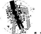
图3图1中的专用保养系统沿III-III线切开的剖面图。The sectional view of the special maintenance system in Fig. 1 along the line III-III.
图4为图1和3中的专用保养系统的冷却装置用图3中的圆圈IV限定的区域的剖面详图。FIG. 4 is a detailed cross-sectional view of the cooling device of the dedicated maintenance system of FIGS. 1 and 3 in the area delimited by circle IV in FIG. 3 .
图5为本发明第二实施例的冷却装置中的导热装置一部分的剖面图。5 is a cross-sectional view of a part of the heat conducting device in the cooling device according to the second embodiment of the present invention.
图1和3所示为一包括专用保养装置2和冷却装置3的专用保养系统1。该专用保养装置2为一毛发去除装置2,用该装置可从人体区域上去除毛发。为了使毛发能被去除,该毛发去除装置2具有一组互相靠近设置并通过齿轮箱6被电动机5驱动旋转的毛发去除刀盘4。这种毛发去除装置2很常见并且不是本发明要说明的主要内容,因为不再详述。1 and 3 show a dedicated maintenance system 1 comprising a
在图2中示出其自身、在图3中示出其细部的冷却装置3具有一个壳体7。该壳体7包括两个由塑料制成的半爿8和9并且液密密封地被焊接在一起。在该壳体7内含有主要为水加上合适的添加剂而制成的冷却剂。在第一半爿壳体8的区域内,冷却装置3设有一个可按压的突起10,使用该突起可将冷却装置3连接到毛发去除装置2上,这样便能使冷却装置3和毛发去除装置2的构成一个适宜实际操作的工作组合即专用保养系统1。The cooling device 3 , shown itself in FIG. 2 and in detail in FIG. 3 , has a housing 7 . The housing 7 comprises two plastic halves 8 and 9 and are welded together in a liquid-tight manner. The housing 7 contains a coolant consisting essentially of water plus suitable additives. In the area of the first half shell 8, the cooling device 3 is provided with a depressible protrusion 10, which can be used to connect the cooling device 3 to the
冷却装置3还具有一个导热装置11。该导热装置11包括一个完全被容纳在壳体7内并与冷却剂热接触的第一部,一个延伸通过壳体7即在图4中按箭头13所指通道方向通过半爿壳体8的第二部14,和一个要被用来冷却人体上要被冷却区域的第三部15。在本例中,导热装置11具有两个挤压的铝制型材,其中第一挤压型材构成第一部12而第二挤压型材构成第二部14和第三部15。这两型材被压迫操作构成的压迫接头连接在一起。第一部12被设计成基本如板状并且略微倾斜成一角度使其外形尽可能与壳体7的形状接近而相配。应该注意到第一部12也可由冲压件构成。第三部15具有一个连接部16以便与第二部14连结成为一件,一个从连接部16伸出的主要冷却部17,及一个与连接部16和主要冷却部17都连接而基本上为U字形的额外冷却部18。在该U形件设有许多进入小孔使毛发能够进入而到达成组毛发去除刀盘上。The cooling device 3 also has a heat conduction device 11 . The heat conduction device 11 includes a first part that is fully accommodated in the housing 7 and is in thermal contact with the coolant, and extends through the housing 7, that is, passes through the half-valve housing 8 in the direction of the passage indicated by the arrow 13 in FIG. 4 A second part 14, and a third part 15 to be used to cool the area of the body to be cooled. In the present example, the heat conduction device 11 has two extruded aluminum profiles, wherein the first extruded profile forms the first part 12 and the second extruded profile forms the second part 14 and the third part 15 . The two profiles are connected together by a compression joint formed by a compression operation. The first part 12 is designed to be substantially plate-shaped and slightly inclined at an angle so that its shape matches the shape of the housing 7 as closely as possible. It should be noted that the first part 12 could also be formed from a stamped part. The third part 15 has a connecting part 16 so as to be connected into one piece with the second part 14, a main cooling part 17 protruding from the connecting part 16, and a connecting part 16 and the main cooling part 17 all connected to be basically U-shaped
导热装置11在其第二部14上设有六个在通道的横向上伸出而在第二部14的外表面上敞开的槽状凹陷。在本例中这六个槽状凹陷基本上为燕尾形状。每一个槽状凹陷21都由一个底壁22及两个侧壁23和24形成。这两个侧壁23和24一方面与底壁22连接,另一方面与第二部14的外表面20连接。凹陷侧壁23和24的形状的特别有效的做法是使壳体7上的部分25和26能在后面将侧壁23和24钩住。这两部分25和26如同整个壳体半爿8那样,在导热装置11的第二部14的周围用注射模塑法制出。这样便可在壳体上制出带状突起31,其中部分25和26的目的和设计是要在侧壁23和24的后面将它们钩住。The heat conducting device 11 is provided on its second part 14 with six groove-like depressions projecting in the transverse direction of the channel and opening on the outer surface of the second part 14 . These six groove-like depressions are substantially dovetail-shaped in this example. Each groove-like depression 21 is formed by a bottom wall 22 and two
由于侧壁23和24的上述槽状凹陷21及带状突起31的形式,人们总是能够得到令人满意的密封,这样便可靠地防止在通过冷却装置3的壳体7的第二部14的区域内冷却剂从冷却装置内不希望地泄漏出来,这就是说,即使在冷却装置3暴露于高温差时也如此。这实际上是发生的,因为该冷却装置例如被安置在致冷器的冰冻框或冰冻室内而使它温度下降,而此刻使用时,被可处于高温的周围空气所包围。Due to the form of the above-mentioned groove-shaped recesses 21 and strip-shaped protrusions 31 of the
在本发明的第二实施例中,冷却装置3的导热装置11的第二部在图5中概略地示出。在本例中设有三个槽状凹陷27并且自身闭合成环状。每一槽状凹陷也都由一个底壁28和两个侧壁29、30形成,只是这些壁被连成一个弧形,而侧壁29和30的形状使壳体上的带状突起(未示出)能从后面将它们钩住。In a second embodiment of the invention, the second part of the heat conducting device 11 of the cooling device 3 is schematically shown in FIG. 5 . In the present example three groove-like recesses 27 are provided and are closed on themselves in a ring. Each groove-shaped depression is also all formed by a bottom wall 28 and two side walls 29, 30, but these walls are connected into an arc, and the shape of the side walls 29 and 30 makes the strip-like protrusion on the housing (not shown) shown) to hook them from behind.
在上面图1到5的说明中,槽状凹陷21和27是设在导热装置11的第二部14上,而带状突起31是设在冷却装置3的壳体7上。但也可能将带状突起设在导热装置上而将槽状凹陷设在壳体上,这样做的好处是不会因凹槽而引起该导热装置材料的削弱。In the above description of FIGS. 1 to 5 , the groove-shaped recesses 21 and 27 are provided on the second portion 14 of the heat conducting device 11 , and the band-shaped protrusion 31 is provided on the housing 7 of the cooling device 3 . However, it is also possible to provide strip-shaped protrusions on the heat conduction device and groove-shaped depressions on the housing. The advantage of doing this is that the material of the heat conduction device will not be weakened by the grooves.
上面在图1到4中说明的是一个具有毛发去除装置2和冷却装置3的专用保养系统1.但本发明还可用于其他方面,如一个使用按摩单元或循环刺激单元的专用保养系统,其时在皮肤处理用具中用到针状或销状处理件,使用冷却装置可减少疼痛的感觉。What has been described above in FIGS. 1 to 4 is a special maintenance system 1 with a
Claims (12)
Translated fromChineseApplications Claiming Priority (2)
| Application Number | Priority Date | Filing Date | Title |
|---|---|---|---|
| EP02100111 | 2002-02-06 | ||
| EP02100111.0 | 2002-02-06 |
Publications (2)
| Publication Number | Publication Date |
|---|---|
| CN1627926Atrue CN1627926A (en) | 2005-06-15 |
| CN1273096C CN1273096C (en) | 2006-09-06 |
Family
ID=27675736
Family Applications (1)
| Application Number | Title | Priority Date | Filing Date |
|---|---|---|---|
| CN03803338.0AExpired - Fee RelatedCN1273096C (en) | 2002-02-06 | 2003-01-23 | Personal care system with a personal care device and a cooling device |
Country Status (8)
| Country | Link |
|---|---|
| US (1) | US20050080432A1 (en) |
| EP (1) | EP1478312B1 (en) |
| JP (1) | JP4257210B2 (en) |
| CN (1) | CN1273096C (en) |
| AT (1) | ATE339169T1 (en) |
| AU (1) | AU2003201135A1 (en) |
| DE (1) | DE60308326T2 (en) |
| WO (1) | WO2003065948A1 (en) |
Cited By (2)
| Publication number | Priority date | Publication date | Assignee | Title |
|---|---|---|---|---|
| CN101965138B (en)* | 2008-03-13 | 2012-08-08 | 博朗公司 | Hair removal device |
| CN101978228B (en)* | 2008-03-25 | 2013-06-05 | 皇家飞利浦电子股份有限公司 | Docking station system including a skin treatment device and used in a skin treatment device |
Families Citing this family (7)
| Publication number | Priority date | Publication date | Assignee | Title |
|---|---|---|---|---|
| EP1758480A1 (en) | 2004-06-14 | 2007-03-07 | Koninklijke Philips Electronics N.V. | A personal care system with movable cooling surface |
| CN101094868B (en)* | 2004-09-03 | 2013-07-10 | 健泰科生物技术公司 | Humanized anti-β7 antagonists and applications thereof |
| CN101031217B (en)* | 2004-09-30 | 2011-04-06 | 皇家飞利浦电子股份有限公司 | Epilator |
| USD541473S1 (en)* | 2005-08-16 | 2007-04-24 | Koninklijke Philips Electronics N.V. | Epilator with ice cube |
| RU2327399C2 (en)* | 2006-02-03 | 2008-06-27 | Государственное Образовательное Учреждение Высшего Профессионального Образования "Дагестанский Государственный Технический Университет" (Дгту) | Thermoelectric module for epilator |
| JP5411168B2 (en)* | 2008-02-22 | 2014-02-12 | コーニンクレッカ フィリップス エヌ ヴェ | Epilator with replaceable cap |
| KR101540645B1 (en)* | 2014-11-19 | 2015-08-03 | (주)하배런메디엔뷰티 | Hair removing apparatus |
Family Cites Families (7)
| Publication number | Priority date | Publication date | Assignee | Title |
|---|---|---|---|---|
| US1209948A (en)* | 1915-06-15 | 1916-12-26 | Flannery Bolt Co | Bar for bolt-blanks. |
| US1692529A (en)* | 1926-01-29 | 1928-11-20 | American Luigi Corp | Machine for making hollow tubes or conductors |
| US2793571A (en)* | 1949-11-15 | 1957-05-28 | Us Rubber Co | Suction press roll |
| JPS59120704A (en)* | 1982-12-27 | 1984-07-12 | Toshiba Corp | Heat resistant wall body against superhigh temperature |
| IL86872A0 (en)* | 1988-06-27 | 1988-11-30 | Levin Alexander | Auxilliary device for hairplucking apparatus |
| FR2709932B1 (en)* | 1993-09-15 | 1995-11-17 | Seb Sa | Mechanical hair removal device by pulling hairs from the skin. |
| ES2206252T3 (en)* | 1999-06-11 | 2004-05-16 | Koninklijke Philips Electronics N.V. | DEPILATION SYSTEM WITH DEPILING DEVICE AND REFRIGERATION DEVICE THAT HAS CERTAIN PARAMETERS. |
- 2003
- 2003-01-23ATAT03737396Tpatent/ATE339169T1/ennot_activeIP Right Cessation
- 2003-01-23DEDE60308326Tpatent/DE60308326T2/ennot_activeExpired - Lifetime
- 2003-01-23JPJP2003565377Apatent/JP4257210B2/ennot_activeExpired - Fee Related
- 2003-01-23CNCN03803338.0Apatent/CN1273096C/ennot_activeExpired - Fee Related
- 2003-01-23EPEP03737396Apatent/EP1478312B1/ennot_activeExpired - Lifetime
- 2003-01-23WOPCT/IB2003/000185patent/WO2003065948A1/enactiveIP Right Grant
- 2003-01-23AUAU2003201135Apatent/AU2003201135A1/ennot_activeAbandoned
- 2003-01-23USUS10/503,423patent/US20050080432A1/ennot_activeAbandoned
Cited By (2)
| Publication number | Priority date | Publication date | Assignee | Title |
|---|---|---|---|---|
| CN101965138B (en)* | 2008-03-13 | 2012-08-08 | 博朗公司 | Hair removal device |
| CN101978228B (en)* | 2008-03-25 | 2013-06-05 | 皇家飞利浦电子股份有限公司 | Docking station system including a skin treatment device and used in a skin treatment device |
Also Published As
| Publication number | Publication date |
|---|---|
| ATE339169T1 (en) | 2006-10-15 |
| DE60308326D1 (en) | 2006-10-26 |
| WO2003065948A1 (en) | 2003-08-14 |
| EP1478312B1 (en) | 2006-09-13 |
| EP1478312A1 (en) | 2004-11-24 |
| JP2005516675A (en) | 2005-06-09 |
| DE60308326T2 (en) | 2007-04-19 |
| AU2003201135A1 (en) | 2003-09-02 |
| US20050080432A1 (en) | 2005-04-14 |
| CN1273096C (en) | 2006-09-06 |
| JP4257210B2 (en) | 2009-04-22 |
Similar Documents
| Publication | Publication Date | Title |
|---|---|---|
| EP4260899A1 (en) | Skin care assembly | |
| CN1627926A (en) | Dedicated maintenance system with dedicated maintenance unit and cooling unit | |
| EP0967665B1 (en) | Thermoelectric converter | |
| EP1940011A3 (en) | Drive unit | |
| CN108136607A (en) | For the electronic sub-component of personal care product | |
| CA2305647A1 (en) | Modular thermoelectric unit and cooling system using same | |
| US20050061473A1 (en) | Flexible heat exchangers | |
| KR100926901B1 (en) | Oxygen Capsule Cooling System | |
| CN213430517U (en) | Semiconductor laser appearance handle that moults | |
| TW200821521A (en) | Cold storage device | |
| CN218960916U (en) | Dehairing instrument | |
| JP2004000375A (en) | Cooling and warming apparatus for face | |
| NO336209B1 (en) | Contact Heats | |
| CN212501591U (en) | Insulin low-temperature storage equipment for diabetes treatment | |
| CN210932187U (en) | Charging ice pack | |
| CN108141983A (en) | Method of assembling electronic sub-assemblies for personal care products | |
| KR20060108844A (en) | Car Coolant Preheater | |
| CN219306920U (en) | Heat dissipation mechanism and laser dehairing instrument | |
| CN111544193B (en) | Charging ice compress bag | |
| KR20150106050A (en) | Cold / hot water generator using thermoelectric element | |
| CN220125372U (en) | Heat exchange structure and treatment handle | |
| JPS6041482Y2 (en) | heat exchange equipment | |
| KR200252610Y1 (en) | Cooling and warming equipment for motor vehicles | |
| KR200216027Y1 (en) | Thermoelectric Module Fixture of Kimchi Storage | |
| JPH0640671U (en) | Heat storage |
Legal Events
| Date | Code | Title | Description |
|---|---|---|---|
| C06 | Publication | ||
| PB01 | Publication | ||
| C10 | Entry into substantive examination | ||
| SE01 | Entry into force of request for substantive examination | ||
| C14 | Grant of patent or utility model | ||
| GR01 | Patent grant | ||
| CF01 | Termination of patent right due to non-payment of annual fee | Granted publication date:20060906 Termination date:20170123 | |
| CF01 | Termination of patent right due to non-payment of annual fee |