CN1626466A - Holder for checking glass substrate - Google Patents
Holder for checking glass substrateDownload PDFInfo
- Publication number
- CN1626466A CN1626466ACNA2004100019894ACN200410001989ACN1626466ACN 1626466 ACN1626466 ACN 1626466ACN A2004100019894 ACNA2004100019894 ACN A2004100019894ACN 200410001989 ACN200410001989 ACN 200410001989ACN 1626466 ACN1626466 ACN 1626466A
- Authority
- CN
- China
- Prior art keywords
- glass substrate
- mentioned
- air cylinder
- fixed frame
- inspecting
- Prior art date
- Legal status (The legal status is an assumption and is not a legal conclusion. Google has not performed a legal analysis and makes no representation as to the accuracy of the status listed.)
- Granted
Links
Images


Classifications
- G—PHYSICS
- G02—OPTICS
- G02F—OPTICAL DEVICES OR ARRANGEMENTS FOR THE CONTROL OF LIGHT BY MODIFICATION OF THE OPTICAL PROPERTIES OF THE MEDIA OF THE ELEMENTS INVOLVED THEREIN; NON-LINEAR OPTICS; FREQUENCY-CHANGING OF LIGHT; OPTICAL LOGIC ELEMENTS; OPTICAL ANALOGUE/DIGITAL CONVERTERS
- G02F1/00—Devices or arrangements for the control of the intensity, colour, phase, polarisation or direction of light arriving from an independent light source, e.g. switching, gating or modulating; Non-linear optics
- G02F1/01—Devices or arrangements for the control of the intensity, colour, phase, polarisation or direction of light arriving from an independent light source, e.g. switching, gating or modulating; Non-linear optics for the control of the intensity, phase, polarisation or colour
- G02F1/13—Devices or arrangements for the control of the intensity, colour, phase, polarisation or direction of light arriving from an independent light source, e.g. switching, gating or modulating; Non-linear optics for the control of the intensity, phase, polarisation or colour based on liquid crystals, e.g. single liquid crystal display cells
- Y—GENERAL TAGGING OF NEW TECHNOLOGICAL DEVELOPMENTS; GENERAL TAGGING OF CROSS-SECTIONAL TECHNOLOGIES SPANNING OVER SEVERAL SECTIONS OF THE IPC; TECHNICAL SUBJECTS COVERED BY FORMER USPC CROSS-REFERENCE ART COLLECTIONS [XRACs] AND DIGESTS
- Y02—TECHNOLOGIES OR APPLICATIONS FOR MITIGATION OR ADAPTATION AGAINST CLIMATE CHANGE
- Y02P—CLIMATE CHANGE MITIGATION TECHNOLOGIES IN THE PRODUCTION OR PROCESSING OF GOODS
- Y02P40/00—Technologies relating to the processing of minerals
- Y02P40/50—Glass production, e.g. reusing waste heat during processing or shaping
- Y02P40/57—Improving the yield, e-g- reduction of reject rates
Landscapes
- Physics & Mathematics (AREA)
- Nonlinear Science (AREA)
- Chemical & Material Sciences (AREA)
- Crystallography & Structural Chemistry (AREA)
- General Physics & Mathematics (AREA)
- Optics & Photonics (AREA)
- Investigating Materials By The Use Of Optical Means Adapted For Particular Applications (AREA)
- Liquid Crystal (AREA)
- Jigs For Machine Tools (AREA)
- Container, Conveyance, Adherence, Positioning, Of Wafer (AREA)
Abstract
Translated fromChinese
Description
Translated fromChinese技术领域technical field
本发明涉及检查玻璃基板用的夹持装置,特别涉及一种检查玻璃基板用的夹持装置,在成形工序中检查玻璃基板时,不仅容易进行将玻璃基板加载到检查区和从检查区卸载玻璃基板的作业,而且缩短检查所需的时间,使与玻璃基板的物理接触最小化来抑制缺陷的发生,而且防止玻璃基板的振动来进行正确的检查。The present invention relates to a clamping device for inspecting glass substrates, and more particularly to a clamping device for inspecting glass substrates. When inspecting glass substrates in a forming process, it is not only easy to load the glass substrate into the inspection area and unload the glass from the inspection area. The operation of the substrate, and shorten the time required for inspection, minimize the physical contact with the glass substrate to suppress the occurrence of defects, and prevent the vibration of the glass substrate to perform accurate inspection.
背景技术Background technique
一般,TFT-LCD(薄膜晶体管液晶显示器)、PDP(等离子体显示屏)、EL(Electro luminescence,场致发光)等平板显示器的制造领域所用的玻璃基板,是在成形工序中将由玻璃熔化炉熔化了的玻璃液供给到熔化成形机来制造,由切断机(cutting apparatus)按初步规格切断,由输送系统传送到加工线上。Generally, glass substrates used in the manufacturing fields of flat panel displays such as TFT-LCD (thin film transistor liquid crystal display), PDP (plasma display), EL (Electro luminescence, electroluminescence) are melted by a glass melting furnace in the forming process. The molten glass is supplied to the melting and forming machine for manufacture, cut off by the cutting apparatus according to the preliminary specifications, and sent to the processing line by the conveying system.
成形工序中的玻璃基板的检查有下述效果:通过事先阻止向后续工序投入次品,来降低成本,提高成品率。在成形工序中,为了由检查输送系统传送来的玻璃基板,需要将玻璃基板从输送系统中卸下并设置到检查位置上。此时,需要充分考虑下述等方面。The inspection of the glass substrate in the forming process has the effect of reducing costs and improving yield by preventing defective products from being introduced into subsequent processes in advance. In the forming process, in order to inspect the glass substrate conveyed by the conveying system, it is necessary to remove the glass substrate from the conveying system and set it at an inspection position. At this time, it is necessary to fully consider the following points and the like.
第一,需要容易进行将玻璃基板加载到检查位置或从检查位置卸载玻璃基板的作业,并且缩短检查所花的时间,而且需要在检查时防止与玻璃基板物理接触来最大限度抑制玻璃基板的缺陷的发生。第二,在检查时,需要使玻璃基板的振动最小化来进行正确的检查。First, it is necessary to facilitate the work of loading and unloading glass substrates to and from the inspection position, shorten the time required for inspection, and prevent physical contact with the glass substrate during inspection to minimize defects in the glass substrate happened. Second, during inspection, it is necessary to minimize the vibration of the glass substrate and perform accurate inspection.
因此,考虑上述等方面,需要开发夹持玻璃基板的装置,使得在成形工序中能够检查玻璃基板,由此,需要在成形工序中容易、迅速而且正确地进行玻璃基板的检查。Therefore, in consideration of the above and other points, it is necessary to develop an apparatus for clamping a glass substrate so that the glass substrate can be inspected during the forming process, thereby requiring easy, rapid and accurate inspection of the glass substrate during the forming process.
发明内容Contents of the invention
本发明就是鉴于上记情况而提出的,其目的在于提供一种检查玻璃基板用的夹持装置,在成形工序中检查玻璃基板时,不仅容易进行将玻璃基板加载到检查区和从检查区卸载玻璃基板的作业,而且缩短检查所需的时间,使与玻璃基板的物理接触最小化来抑制缺陷的发生,而且防止玻璃基板的振动来进行正确的检查。The present invention is made in view of the above circumstances, and its object is to provide a clamping device for inspecting glass substrates, which not only facilitates loading and unloading of glass substrates to and from the inspection area when inspecting glass substrates in the forming process The operation of the glass substrate not only shortens the time required for inspection, minimizes the physical contact with the glass substrate to suppress the occurrence of defects, but also prevents the vibration of the glass substrate to perform accurate inspection.
为了实现这种目的,本发明提供一种检查玻璃基板用的夹持装置,为了检查玻璃基板而将其夹持在检查区中,包括:上部夹持机构,由设置在检查区中的固定框架和分别设置在固定框架的上侧且夹持玻璃基板的上端部的第1及第2上部夹具构成,第1上部夹具被固定在固定框架的上侧,第2上部夹具被设置成沿固定框架的上侧自如地左右移动;下部夹持机构,由分别设置在固定框架的下侧、夹持玻璃基板的下端部且将玻璃基板拉向下方以使得玻璃基板被上下拉伸的第1及第2下部夹具构成,第1下部夹具被固定在固定框架的下侧,第2下部夹具被设置成沿固定框架的下侧自如地左右移动;以及侧部夹持机构,由分别设置在固定框架的两侧、夹持玻璃基板的两端部且将玻璃基板拉向两侧以使得玻璃基板被左右拉伸的多个侧部夹具构成。In order to achieve this purpose, the present invention provides a clamping device for inspecting a glass substrate, which is clamped in the inspection area for inspecting the glass substrate, comprising: an upper clamping mechanism, which is formed by a fixed frame arranged in the inspection area It is composed of first and second upper clamps respectively arranged on the upper side of the fixed frame and clamping the upper end of the glass substrate. The first upper clamp is fixed on the upper side of the fixed frame, and the second upper clamp is arranged along the fixed frame. The upper side of the upper side moves freely left and right; the lower clamping mechanism consists of the first and second clamping mechanisms respectively arranged on the lower side of the fixed frame to clamp the lower end of the glass substrate and pull the glass substrate downward so that the glass substrate is stretched up and down. 2 lower clamps, the first lower clamp is fixed on the lower side of the fixed frame, the second lower clamp is set to move freely left and right along the lower side of the fixed frame; The two sides are composed of a plurality of side clamps that clamp both ends of the glass substrate and pull the glass substrate to both sides so that the glass substrate is stretched left and right.
发明的效果The effect of the invention
根据本发明的检查玻璃基板用的夹持装置具有下述效果:在成形工序中检查玻璃基板时,不仅容易进行将玻璃基板加载到检查位置和从检查位置卸载玻璃基板的作业,而且缩短检查所需的时间,使与玻璃基板的物理接触最小化来抑制缺陷的发生,而且防止玻璃基板的振动来进行正确的检查。The clamping device for inspecting a glass substrate according to the present invention has the following effects: when inspecting a glass substrate in a forming process, it is not only easy to carry out the work of loading and unloading the glass substrate to and from the inspection position, but also shortens the inspection time. The time required, the physical contact with the glass substrate is minimized to suppress the occurrence of defects, and the vibration of the glass substrate is prevented to perform a correct inspection.
附图说明Description of drawings
图1是本发明的检查玻璃基板用的夹持装置的正视图。Fig. 1 is a front view of a clamping device for inspecting a glass substrate according to the present invention.
图2是本发明的检查玻璃基板用的夹持装置的第1上部夹具的正视图。Fig. 2 is a front view of a first upper clamp of the clamping device for inspecting a glass substrate according to the present invention.
图3是本发明的检查玻璃基板用的夹持装置的第1上部夹具的侧视图。Fig. 3 is a side view of a first upper clamp of the clamping device for inspecting a glass substrate according to the present invention.
图4是本发明的检查玻璃基板用的夹持装置的第2上部夹具的正视图。Fig. 4 is a front view of a second upper clamp of the clamping device for inspecting a glass substrate according to the present invention.
图5是本发明的检查玻璃基板用的夹持装置的第2上部夹具的底视图。Fig. 5 is a bottom view of a second upper clamp of the clamping device for inspecting a glass substrate according to the present invention.
图6是本发明的检查玻璃基板用的夹持装置的第1下部夹具的正视图。Fig. 6 is a front view of a first lower clamp of the clamping device for inspecting a glass substrate according to the present invention.
图7是本发明的检查玻璃基板用的夹持装置的第1下部夹具的侧视图。Fig. 7 is a side view of a first lower clamp of the clamping device for inspecting a glass substrate according to the present invention.
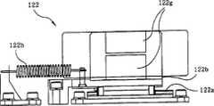
图8是本发明的检查玻璃基板用的夹持装置的第2下部夹具的正视图。Fig. 8 is a front view of a second lower clamp of the clamping device for inspecting a glass substrate according to the present invention.
图9是本发明的检查玻璃基板用的夹持装置的第2下部夹具的平面图。Fig. 9 is a plan view of a second lower clamp of the clamping device for inspecting a glass substrate according to the present invention.
图10是本发明的检查玻璃基板用的夹持装置的侧部夹具的正视图。10 is a front view of a side clamp of the clamping device for inspecting a glass substrate according to the present invention.
图11是本发明的检查玻璃基板用的夹持装置的侧部夹具的侧视图。Fig. 11 is a side view of a side clamp of the clamping device for inspecting a glass substrate according to the present invention.
图12是使用本发明的检查玻璃基板用的夹持装置的玻璃基板检查装置的正视图。Fig. 12 is a front view of a glass substrate inspection device using the clamping device for inspecting a glass substrate according to the present invention.
图13是使用本发明的检查玻璃基板用的夹持装置的玻璃基板检查装置的侧视图。Fig. 13 is a side view of a glass substrate inspection device using the clamping device for inspecting a glass substrate according to the present invention.
图14是使用本发明的检查玻璃基板用的夹持装置的玻璃基板检查装置的平面图。Fig. 14 is a plan view of a glass substrate inspection device using the clamping device for inspecting a glass substrate according to the present invention.
图15是使用本发明的检查玻璃基板用的夹持装置的玻璃基板检查装置中的视频组件的透视图。Fig. 15 is a perspective view of a video module in a glass substrate inspection device using the clamping device for inspecting a glass substrate of the present invention.
图16是使用本发明的检查玻璃基板用的夹持装置的玻璃基板检查装置的结构图。Fig. 16 is a configuration diagram of a glass substrate inspection device using the clamping device for inspecting a glass substrate according to the present invention.
具体实施方式Detailed ways
以下,参照附图来详细说明本发明的优选实施方式。Hereinafter, preferred embodiments of the present invention will be described in detail with reference to the drawings.
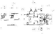
图1是本发明的检查玻璃基板用的夹持装置的正视图。Fig. 1 is a front view of a clamping device for inspecting a glass substrate according to the present invention.
如图所示,本发明的检查玻璃基板用的夹持装置100是为了在成形工序中检查玻璃基板1而将其夹持到检查区中的装置100,包含:固定框架140;上部夹持机构110,被分别设置在固定框架140的上侧,夹持玻璃基板1的上端部;下部夹持机构120,被分别设置在固定框架140的下侧,夹持玻璃基板1的下端部,并且将玻璃基板1拉向下方,使得玻璃基板1上下拉伸;以及侧部夹持机构130,被分别设置在固定框架140的两侧,夹持玻璃基板1的两端部,并且将玻璃基板1拉向两侧,使得玻璃基板1左右拉伸。As shown in the figure, the
固定框架140被设置在用于在成形工序中检查玻璃基板1的位置上,分别位于上侧和下侧的上部及下部框架141、142通过一对侧部框架143连结。The fixed
上部夹持机构110由分别设置在固定框架140的上侧、即上部框架141上、夹持玻璃基板1的上端部的第1及第2上部夹具111、112构成,第1上部夹具111被固定在固定框架140的上部框架141上,第2上部夹具112被设置成可沿固定框架140的上部框架141自如地左右移动。The
在图2及图3所示的第1上部夹具111中,在固定框架140的上侧框架141上通过托架141a设置有第1空压气缸111a,用气压使与第1空压气缸111a的端部、即下端旋转自如地结合的一对夹子111c相互闭合、打开,以便抓住、放开玻璃基板1的上端部。In the first
第1空压气缸111a通过一对孔111b选择性地被供给气压,使一对夹子111c旋转而相互闭合、打开,在夹子111c闭合时,使其端部把持玻璃基板1的上端部。图4及图5所示的第2上部夹具112为了沿设置在固定框架140的上侧、即上部框架141上的导轨112a滑动,设置有第2空压气缸112b,第2空压气缸112b通过气压使与端部旋转自如地结合的一对夹子112d相互闭合、打开,以便抓住、放开玻璃基板1的上端部。The first air cylinder 111a is selectively supplied with air pressure through the pair of holes 111b to rotate the pair of clips 111c to close and open each other, and when the clips 111c are closed, the ends grip the upper end of the
第2空压气缸112b滑动自如地设置在沿下部框架142的长度方向并设在上部框架141上的导轨112a上,通过向一对孔112c选择性地供给的气压,使夹子112d旋转来相互闭合、打开,在夹子112d闭合时,使其端部把持玻璃基板1的上端部。The second air cylinder 112b is slidably provided on the guide rail 112a provided on the
在第2上部夹具112中,将第2空压气缸112b滑动自如地设置在导轨112a上,在侧部夹持机构130将玻璃基板1左右拉伸的情况下,通过第2上部夹具112沿玻璃基板1被拉伸的方向移动,使得玻璃基板1在整个区域上被拉伸。In the second
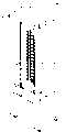
在第2上部夹具112中,为了使由于玻璃基板1被左右拉伸而移动了的第2空压气缸112b在除去玻璃基板1后回到原来位置,在固定框架140的上侧、即上部框架141和第2空压气缸112b上设置螺旋弹簧这样的弹性部件112e。In the second
下部夹持机构120由分别设置在固定框架140的下侧即下部框架142上、夹持玻璃基板1的下端部、并将玻璃基板1拉向下方以使得玻璃基板1被上下拉伸的第1及第2下部夹具121、122构成,第1下部夹具121被固定在下部框架142上,第2下部夹具122被设置成可沿下部框架142自如地左右移动。The
图6及图7所示的第1下部夹具121在固定框架140的下侧、即下部框架142上设置有具有通过气压上下往复移动的移动部件121b的第3空压气缸121a,在第3空压气缸121a的移动部件121b的端部设置有第4空压气缸121d,第4空压气缸121d通过气压使与端部旋转自如地结合的一对夹子121f相互闭合、打开,以便抓住、放开玻璃基板1的下端部。The first
第3空压气缸121a通过一对孔121c选择性地被供给气压,使移动部件121b往复移动,从而使第4空压气缸121d上下往复移动。第4空压气缸121d通过一对孔121e选择性地被供给气压,使一对夹子121f旋转而相互闭合、打开,由此,在夹子121f闭合时,使其端部把持玻璃基板1的下端部。The third air cylinder 121a is selectively supplied with air pressure through a pair of holes 121c, reciprocates the moving member 121b, and reciprocates the fourth air cylinder 121d up and down. The fourth air cylinder 121d is selectively supplied with air pressure through the pair of holes 121e to rotate the pair of
图8及图9所示的第2下部夹具122为了沿设置在固定框架140的下侧、即下部框架142上的导轨122a滑动,设置有第5空压气缸122b,第5空压气缸122b具有通过气压上下往复移动的移动部件122c,在第5空压气缸122b的移动部件122c的端部设置有第6空压气缸122e,第6空压气缸122e通过气压使与端部旋转自如地结合的一对夹子122g相互闭合、打开,以便抓住、放开玻璃基板1的下端部。The 2nd
第5空压气缸122b可滑动自如地设置在沿下部框架142的长度方向并设在下部框架142上的导轨122a上,通过一对孔(未图示)选择性地被供给气压,使移动部件122c往复移动,从而使与移动部件122c结合的第6空压气缸122e上下往复移动。The
第6空压气缸122e通过一对孔122f选择性地被供给气压,从而使一对夹子122g旋转而相互闭合、打开,在夹子122g闭合时,使其端部把持玻璃基板1的下端部。在第2下部夹具122中,将第5空压气缸122b滑动自如地设置在导轨122a上,在侧部夹持机构130使玻璃基板1被左右拉伸的情况下,通过第2下部夹具122沿玻璃基板1被拉伸的方向移动,使得玻璃基板1在整个区域上被拉伸。The
第2下部夹具122为了使由于玻璃基板1被左右拉伸而移动了的第5空压气缸122b在除去玻璃基板1后回到原来位置,在固定框架140的下侧、即下部框架142和第5空压气缸122b上设置有螺旋弹簧这样的弹性部件122h。The second
侧部夹持机构130由分别设置在固定框架140的两侧即每个侧部框架143上、夹持玻璃基板1的两端部并将玻璃基板1拉向两侧以使得玻璃基板1被左右拉伸的多个侧部夹具131构成。The
图10及图11所示的侧部夹具131在固定框架140的一侧、即侧部框架143上设置有具有通过气压左右往复移动的移动部件131b的第7空压气缸131a,在第7空压气缸131a的移动部件131b的端部设置有第8空压气缸131d,第8空压气缸131d通过气压使与端部旋转自如地结合的一对夹子131f相互闭合、打开,以便抓住、放开玻璃基板1的侧端部。The
第7空压气缸131a通过一对孔131c选择性地被供给气压,使移动部件131b往复移动,从而使与移动部件131b结合的第8空压气缸131d左右往复移动。第8空压气缸131d通过一对孔131e选择性地被供给气压,使一对夹子131f旋转而相互闭合、打开,在夹子131f闭合时,使其端部把持玻璃基板1的下端部。The
下部夹持机构120的第1及第2下部夹具121、122和侧部夹持机构130的侧部夹具131,为了在夹持玻璃基板1时能够定位在夹持玻璃基板1的位置上,设有支持玻璃基板1的端部的对准器121g、122i、131g。The first and second
各个对准器121g、122i、131g在分别与第3空压气缸121a、第5空压气缸122b及第7空压气缸131a的端部结合的托架121h、122j、131h的两侧各设置1个。图12至图16是利用本发明的检查玻璃基板用的夹持装置在成形工程中检查玻璃基板1的装置的示意图。如图所示,利用了本发明的检查玻璃基板用夹持装置的玻璃基板检查装置包括:视频组件200,为了检查玻璃基板扫描被夹持装置100固定的玻璃基板1;视频组件移动机构300,使视频组件200从玻璃基板1的一侧向另一侧移动;缺陷数据处理部400,根据用视频组件200扫描到的图像对玻璃基板1的缺陷进行数据化并进行处理;以及显示部500,显示缺陷数据处理部400处理的数据。Each
如图15所示,视频组件200位于被检查玻璃基板用的夹持装置100固定的玻璃基板1的一侧,用照明210进行光照射并用多个摄像机220扫描玻璃基板1。视频组件200在一侧开放的视觉框架230内侧的两方分别垂直设置有摄像机固定部件240和照明固定部件250,在摄像机固定部件240上固定有多个摄像机220以便经开放的一侧来扫描玻璃基板1,在照明固定部件250上设置有照明210以便向多个摄像机220的扫描领域进行光照射。As shown in FIG. 15 , the
视频组件移动机构300为了使视频组件200的摄像机220扫描玻璃基板1的整个区域,使视频组件200从玻璃基板1的一侧向另一侧移动。在视频组件移动机构300中,在视频组件移动机构300的框架315的下部旋转自如地设置有第1丝杠310,在第1丝杠310上以螺纹配合方式设置有移动架(カ一ト)320,在移动架320的上侧结合有视频组件200,在第1丝杠310上连结有第1传送电机(未图示),在框架315的上部与第1丝杠310平行且旋转自如地设置有第2丝杠340,与第2丝杠340螺合的球状螺母350被固定在视频组件200的视觉框架230上,使第2丝杠340旋转的第2移动电机360与第2丝杠340机械连结。The video unit moving mechanism 300 moves the
第2丝杠340通过被设置在移动架320的上侧的支承框架330支承其两端,而被设置成旋转自如。缺陷数据处理部400根据从视频组件200的摄像机220传送来的图像对玻璃基板1的缺陷的个数、大小、位置等进行数据化并进行处理。The
显示部500将缺陷数据处理部400处理的玻璃基板1的缺陷的个数、大小、位置等数据向外部显示。这种构造的检查玻璃基板用的夹持装置100的作用如下进行。在成形工序中成形的上端被固定在传送夹子(未图示)上,使沿传送轨道(未图示)传送的玻璃基板1停止后,从传送夹子(未图示)中取下玻璃基板1并使其位于固定框架140的内侧后,用上部夹持机构110的第1及第2上部夹具111、112夹持玻璃基板1的上端部。The display unit 500 externally displays data such as the number, size, and position of defects in the
即,使第1及第2上部夹具111、112的第1及第2空压气缸111a、112b动作,用夹子111c、112d夹持玻璃基板1的上端部。另一方面,在使玻璃基板1位于固定框架140的内侧时,使玻璃基板1位于下部夹持机构120及侧部夹持机构130的对准器121g、122h、131g上,由此,能够容易地定位在夹持位置上。That is, the first and second air cylinders 111a, 112b of the first and second
用上部夹持机构110夹持玻璃基板1的上端部后,用下部夹持机构120夹持玻璃基板1的下端部。即,使下部夹持机构120的第4及第6空压气缸121d、122e动作,用下部夹持机构120的夹子121f、122g夹持玻璃基板1的下端部。After the upper end of the
玻璃基板1的上端和下端分别由上部及下部夹持机构110、120夹持后,使下部夹持机构120的第3及第5空压气缸121a、122b动作,将玻璃基板1以一定的力量拉向下方而使其上下拉伸。After the upper end and the lower end of the
玻璃基板1被上下拉伸后,侧部夹持机构130的第8空压气缸131d动作,用夹子131f分别夹持玻璃基板1的侧端部,并且,使第7空压气缸131a动作,将玻璃基板1拉向两侧而使玻璃基板1被左右拉伸。After the
通过侧部夹持机构130的第7空压气缸131a使玻璃基板1被左右拉伸时,在用上部及下部夹持机构110、120的第1上部夹具111和第1下部夹具121将玻璃基板1固定在一定的位置上的状态下,使第2上部夹具112和第1下部夹具122分别沿导轨112a、122a移动,从而使得玻璃基板1在整个区域上被左右拉伸。因此,使玻璃基板1不弯曲,并且使振动最小化,在用视频组件200进行扫描时,可取得鲜明的图像。When the
玻璃基板1由上部及下部夹具110、120和侧部夹具130夹持而拉伸后,用视频组件移动机构300使视频组件200从玻璃基板1的一侧向另一侧移动,在用视频组件200的照明210和多个摄像机220扫描玻璃基板1的整个区域后,用缺陷数据处理部400将进行扫描而取得的图像转变为玻璃基板1的缺陷的个数、大小、位置等数据进行处理并用显示部500进行显示。After the
如上所述,根据本发明的优选实施例,在成形工序中检查玻璃基板时,不仅容易进行将玻璃基板加载到检查位置和从检查位置卸载玻璃基板的作业,而且缩短检查所需的时间,使与玻璃基板的物理接触最小化来抑制缺陷的发生,而且,防止玻璃基板的振动来进行正确的检查。As described above, according to a preferred embodiment of the present invention, when inspecting a glass substrate in a forming process, not only the work of loading and unloading the glass substrate to and from the inspection position is facilitated, but also the time required for the inspection is shortened, enabling The occurrence of defects is suppressed by minimizing the physical contact with the glass substrate, and the vibration of the glass substrate is prevented for accurate inspection.
以上说明了本发明的优选实施方式,但是在不脱离本发明的权利要求书的基础上,本领域的技术人员就能进行各种改变。Preferred embodiments of the present invention have been described above, but those skilled in the art can make various changes without departing from the claims of the present invention.
Claims (9)
Translated fromChineseApplications Claiming Priority (2)
| Application Number | Priority Date | Filing Date | Title |
|---|---|---|---|
| KR1020030088936AKR100582345B1 (en) | 2003-12-09 | 2003-12-09 | Clamping Device for Inspection of Glass Substrate |
| KR0088936/2003 | 2003-12-09 |
Publications (2)
| Publication Number | Publication Date |
|---|---|
| CN1626466Atrue CN1626466A (en) | 2005-06-15 |
| CN1626466B CN1626466B (en) | 2010-05-12 |
Family
ID=34737865
Family Applications (1)
| Application Number | Title | Priority Date | Filing Date |
|---|---|---|---|
| CN2004100019894AExpired - LifetimeCN1626466B (en) | 2003-12-09 | 2004-01-16 | Clamping device for inspecting glass substrates |
Country Status (4)
| Country | Link |
|---|---|
| JP (1) | JP2005172783A (en) |
| KR (1) | KR100582345B1 (en) |
| CN (1) | CN1626466B (en) |
| TW (1) | TWI318784B (en) |
Cited By (16)
| Publication number | Priority date | Publication date | Assignee | Title |
|---|---|---|---|---|
| CN102603199A (en)* | 2011-01-18 | 2012-07-25 | 坤辉科技实业股份有限公司 | Side fixing type glass hanging bracket |
| CN102674006A (en)* | 2011-03-14 | 2012-09-19 | 无锡康力电子有限公司 | Sheet loading frame for glass coating machine |
| CN102963726A (en)* | 2012-11-30 | 2013-03-13 | 江西沃格光电科技有限公司 | Traceless movable glass fixture |
| CN103901044A (en)* | 2012-12-28 | 2014-07-02 | 鸿富锦精密工业(深圳)有限公司 | Detection system |
| CN103988291A (en)* | 2012-03-08 | 2014-08-13 | 日本电气硝子株式会社 | Glass substrate conveyance device and conveyance method |
| CN104608075A (en)* | 2015-02-11 | 2015-05-13 | 中国工程物理研究院激光聚变研究中心 | Fixture for detecting errors of transmission wave surface of large-sized neodymium glass plate |
| CN105116569A (en)* | 2015-09-11 | 2015-12-02 | 昆山精讯电子技术有限公司 | Display panel carrying table and display panel detection device |
| US9426412B2 (en) | 2011-07-13 | 2016-08-23 | Panasonic Intellectual Property Management Co., Ltd. | Rendering device and rendering method |
| CN108214416A (en)* | 2018-01-03 | 2018-06-29 | 京东方科技集团股份有限公司 | Display panel detection workbench |
| CN109031710A (en)* | 2018-03-27 | 2018-12-18 | 赣州市山水智能设备有限公司 | A kind of check device of liquid crystal display |
| CN109799627A (en)* | 2018-12-26 | 2019-05-24 | 江苏东旭亿泰智能装备有限公司 | The macro inspection apparatus of glass substrate |
| CN110053957A (en)* | 2019-04-29 | 2019-07-26 | 东莞市鸿仁自动化设备科技有限公司 | A kind of intelligent stacking system and stacking method of thin plate |
| CN110076454A (en)* | 2019-04-16 | 2019-08-02 | 徐州工业职业技术学院 | A kind of multistation Intelligent optical fiber laser welding machinery workbench |
| CN111438645A (en)* | 2020-04-02 | 2020-07-24 | 深圳市华星光电半导体显示技术有限公司 | Display panel jig |
| CN113511548A (en)* | 2020-04-09 | 2021-10-19 | 群翊工业股份有限公司 | Substrate flattening device and flattening method thereof |
| CN114102007A (en)* | 2021-10-29 | 2022-03-01 | 尹涛 | A sheet metal welding fixture |
Families Citing this family (23)
| Publication number | Priority date | Publication date | Assignee | Title |
|---|---|---|---|---|
| KR101138727B1 (en)* | 2005-08-04 | 2012-04-24 | 엘아이지에이디피 주식회사 | Panel display clamping apparatus and transfering and inspecting apparatuses having the same |
| KR100846682B1 (en)* | 2006-12-11 | 2008-07-17 | (주)테크윙 | High Fix Board Clamping Device for Test Handler |
| KR100824028B1 (en)* | 2007-03-28 | 2008-04-21 | (주)오성엔지니어링 | LC Photomask Gripper |
| JP4985447B2 (en)* | 2007-05-10 | 2012-07-25 | 株式会社Ihi | Substrate transfer device |
| JP4560578B1 (en)* | 2009-03-26 | 2010-10-13 | シャープ株式会社 | LCD panel lighting inspection device |
| KR101045277B1 (en)* | 2009-07-07 | 2011-06-29 | (주)테크윙 | High Fix Board Clamping Device for Test Handler |
| JP5963218B2 (en)* | 2011-09-27 | 2016-08-03 | アプライド マテリアルズ インコーポレイテッドApplied Materials,Incorporated | Carrier for thin glass substrate and method of using the same |
| JP6061182B2 (en)* | 2012-09-07 | 2017-01-18 | 大日本印刷株式会社 | Metal thin plate dimension measuring apparatus and metal thin plate dimension measuring method |
| JP6142486B2 (en)* | 2012-09-07 | 2017-06-07 | 大日本印刷株式会社 | Metal thin plate dimension measuring apparatus and metal thin plate dimension measuring method |
| JP2014080645A (en)* | 2012-10-15 | 2014-05-08 | I Plant:Kk | Substrate holding device |
| CN103245672A (en)* | 2013-05-16 | 2013-08-14 | 西北工业大学 | Fixture for detecting tool wear |
| JP2015034071A (en) | 2013-08-08 | 2015-02-19 | 日本電気硝子株式会社 | Sheet member conveyance device, sheet member support device, sheet member inspection device, and sheet member conveying method |
| CN104003152B (en)* | 2014-04-29 | 2016-03-30 | 雄华机械(苏州)有限公司 | A kind of adjusting mechanism of adjustable rolling wheel track width |
| CN104505352B (en)* | 2014-11-28 | 2017-07-14 | 苏州晟成光伏设备有限公司 | High-order EL check machines centering body |
| KR102683727B1 (en)* | 2015-06-02 | 2024-07-10 | 삼성디스플레이 주식회사 | Method of allining substrate |
| KR102186362B1 (en)* | 2015-06-02 | 2020-12-04 | 삼성디스플레이 주식회사 | Apparatus of alligning substrate and method of allining substrate |
| GB2544741B (en)* | 2015-11-24 | 2017-12-06 | Robert Shillabeer Timothy | Clamp for holding a workpiece for machining |
| FR3049940B1 (en)* | 2016-04-06 | 2018-04-13 | Saint- Gobain Glass France | SUPPORT DEVICE FOR GLASS SHEET IN PARTICULAR IN A WASHING PLANT |
| KR102319387B1 (en)* | 2016-05-26 | 2021-11-01 | 주식회사 아이에스시 | Correcting clamping unit and apparatus of clamping hifix board for test handler having the same |
| CN112851136A (en)* | 2021-02-05 | 2021-05-28 | 安徽科技学院 | Automatic clamp for coating optical glass |
| KR102470535B1 (en)* | 2021-05-03 | 2022-11-28 | 주식회사 티케이씨 | Jig Apparatus For Holding Plate Of Plate Processing System |
| CN114656168B (en)* | 2022-04-06 | 2022-11-25 | 南京萃智激光应用技术研究院有限公司 | Laser welding equipment for glass processing |
| CN115638727A (en)* | 2022-10-28 | 2023-01-24 | 信义汽车玻璃(深圳)有限公司 | Glass positioning table, glass detection system and glass detection method |
Family Cites Families (7)
| Publication number | Priority date | Publication date | Assignee | Title |
|---|---|---|---|---|
| JP3243044B2 (en)* | 1993-03-15 | 2002-01-07 | 株式会社日立製作所 | Substrate processing carrier |
| JP4138926B2 (en)* | 1998-02-13 | 2008-08-27 | 株式会社アマダ | Work clamp device for plate processing equipment |
| AU5257001A (en)* | 2000-04-26 | 2001-11-07 | Olympus Optical Co., Ltd. | Holder mechanism |
| JP2002014309A (en)* | 2000-06-30 | 2002-01-18 | Minolta Co Ltd | Film holder, film housing jig and method for manufacturing liquid crystal display element using those |
| JP2003029657A (en)* | 2001-07-19 | 2003-01-31 | Minolta Co Ltd | Production method for display element and film substrate holder |
| JP2003270155A (en)* | 2002-03-15 | 2003-09-25 | Olympus Optical Co Ltd | Substrate holding device and inspection device |
| JP2003302346A (en)* | 2002-04-12 | 2003-10-24 | Hitachi Electronics Eng Co Ltd | Surface inspection equipment for thin work |
- 2003
- 2003-12-09KRKR1020030088936Apatent/KR100582345B1/ennot_activeExpired - Lifetime
- 2003-12-30TWTW092137454Apatent/TWI318784B/ennot_activeIP Right Cessation
- 2004
- 2004-01-08JPJP2004002984Apatent/JP2005172783A/enactivePending
- 2004-01-16CNCN2004100019894Apatent/CN1626466B/ennot_activeExpired - Lifetime
Cited By (22)
| Publication number | Priority date | Publication date | Assignee | Title |
|---|---|---|---|---|
| CN102603199A (en)* | 2011-01-18 | 2012-07-25 | 坤辉科技实业股份有限公司 | Side fixing type glass hanging bracket |
| CN102674006A (en)* | 2011-03-14 | 2012-09-19 | 无锡康力电子有限公司 | Sheet loading frame for glass coating machine |
| US9426412B2 (en) | 2011-07-13 | 2016-08-23 | Panasonic Intellectual Property Management Co., Ltd. | Rendering device and rendering method |
| CN103988291A (en)* | 2012-03-08 | 2014-08-13 | 日本电气硝子株式会社 | Glass substrate conveyance device and conveyance method |
| CN102963726A (en)* | 2012-11-30 | 2013-03-13 | 江西沃格光电科技有限公司 | Traceless movable glass fixture |
| CN103901044A (en)* | 2012-12-28 | 2014-07-02 | 鸿富锦精密工业(深圳)有限公司 | Detection system |
| CN104608075A (en)* | 2015-02-11 | 2015-05-13 | 中国工程物理研究院激光聚变研究中心 | Fixture for detecting errors of transmission wave surface of large-sized neodymium glass plate |
| CN104608075B (en)* | 2015-02-11 | 2016-04-06 | 中国工程物理研究院激光聚变研究中心 | Large scale neodymium glass transmitted wave surface error detects fixture |
| CN105116569B (en)* | 2015-09-11 | 2018-07-31 | 昆山精讯电子技术有限公司 | Display panel microscope carrier and display panel testing |
| CN105116569A (en)* | 2015-09-11 | 2015-12-02 | 昆山精讯电子技术有限公司 | Display panel carrying table and display panel detection device |
| CN108214416A (en)* | 2018-01-03 | 2018-06-29 | 京东方科技集团股份有限公司 | Display panel detection workbench |
| CN109031710A (en)* | 2018-03-27 | 2018-12-18 | 赣州市山水智能设备有限公司 | A kind of check device of liquid crystal display |
| CN109031710B (en)* | 2018-03-27 | 2023-11-10 | 中山市正科电器实业有限公司 | Inspection device of liquid crystal display |
| CN109799627B (en)* | 2018-12-26 | 2021-11-26 | 江苏宏芯亿泰智能装备有限公司 | Macroscopic inspection device for glass substrate |
| CN109799627A (en)* | 2018-12-26 | 2019-05-24 | 江苏东旭亿泰智能装备有限公司 | The macro inspection apparatus of glass substrate |
| CN110076454A (en)* | 2019-04-16 | 2019-08-02 | 徐州工业职业技术学院 | A kind of multistation Intelligent optical fiber laser welding machinery workbench |
| CN110053957A (en)* | 2019-04-29 | 2019-07-26 | 东莞市鸿仁自动化设备科技有限公司 | A kind of intelligent stacking system and stacking method of thin plate |
| CN111438645A (en)* | 2020-04-02 | 2020-07-24 | 深圳市华星光电半导体显示技术有限公司 | Display panel jig |
| CN111438645B (en)* | 2020-04-02 | 2022-02-22 | 深圳市华星光电半导体显示技术有限公司 | Display panel jig |
| CN113511548A (en)* | 2020-04-09 | 2021-10-19 | 群翊工业股份有限公司 | Substrate flattening device and flattening method thereof |
| CN114102007A (en)* | 2021-10-29 | 2022-03-01 | 尹涛 | A sheet metal welding fixture |
| CN114102007B (en)* | 2021-10-29 | 2023-10-20 | 上海摩太展示用品设计制作有限公司 | Metal plate welding fixture |
Also Published As
| Publication number | Publication date |
|---|---|
| TWI318784B (en) | 2009-12-21 |
| KR20050055884A (en) | 2005-06-14 |
| KR100582345B1 (en) | 2006-05-22 |
| TW200520135A (en) | 2005-06-16 |
| JP2005172783A (en) | 2005-06-30 |
| CN1626466B (en) | 2010-05-12 |
Similar Documents
| Publication | Publication Date | Title |
|---|---|---|
| CN1626466A (en) | Holder for checking glass substrate | |
| JP4729699B2 (en) | Glass substrate inspection apparatus and inspection method | |
| CN1323935C (en) | Conveyer for LCD panel | |
| US20200377303A1 (en) | Inspection Apparatus for Display Panel and Testing Method for Display Panel | |
| KR101471899B1 (en) | Glass substrate inspecting apparatus and glass substrate inspecting method | |
| KR101272299B1 (en) | Apparatus for manufacturing divided mask frame assembly for manufacturing AMOLED panel | |
| CN100557428C (en) | Polarizing film detection apparatus and method | |
| CN1920632A (en) | System and method for cutting liquid crystal display substrate | |
| CN106873195B (en) | Probe unit replacement device | |
| KR101032089B1 (en) | Board Inspection Device | |
| US20100071172A1 (en) | Clamping apparatus with positioning function | |
| CN209939889U (en) | Insert machine | |
| CN113182220B (en) | Display screen state detection device and detection method based on smart phone | |
| KR100788733B1 (en) | Polarizing film inspection device and method | |
| CN1713365A (en) | Bench equipment and control method thereof | |
| KR20160148800A (en) | In-line handler and testing method using the same | |
| CN2776925Y (en) | Substrate transfer positioning device | |
| KR20160028686A (en) | Bending test apparatus for light emitting device package module | |
| CN1721842A (en) | graphic inspection device | |
| CN1727880A (en) | Multiple glass substrate checker and multiple glass substrate check using such checker | |
| KR20070052191A (en) | Lighting inspection device | |
| CN210982961U (en) | Light guide plate bright spot and shadow defect detection device | |
| KR101590454B1 (en) | Lens centering inspection apparatus for light emitting device package module | |
| CN218239879U (en) | Glass substrate's defect detecting device and glass substrate production line | |
| KR100562583B1 (en) | Panel feeder |
Legal Events
| Date | Code | Title | Description |
|---|---|---|---|
| C06 | Publication | ||
| PB01 | Publication | ||
| C10 | Entry into substantive examination | ||
| SE01 | Entry into force of request for substantive examination | ||
| C14 | Grant of patent or utility model | ||
| GR01 | Patent grant | ||
| C56 | Change in the name or address of the patentee | Owner name:SUMSUNG KANGNING PRECISION MATERIAL CO., LTD. Free format text:FORMER NAME: SAMSUNG CORNING PRECISION GLASS | |
| CP01 | Change in the name or title of a patent holder | Address after:Gyeongbuk, South Korea Patentee after:SAMSUNG CORNING PRECISION MATERIALS Co.,Ltd. Address before:Gyeongbuk, South Korea Patentee before:SAMSUNG CORNING PRECISION GLASS CO.,LTD. | |
| C56 | Change in the name or address of the patentee | Owner name:KANGNING PRECISION MATERIAL CO., LTD. Free format text:FORMER NAME: SAMSUNG CORNING PRECISION MATERIALS CO., LTD. | |
| CP03 | Change of name, title or address | Address after:Chungnam, South Korea Patentee after:CORNING PRECISION MATERIALS Co.,Ltd. Address before:Gyeongbuk, South Korea Patentee before:SAMSUNG CORNING PRECISION MATERIALS Co.,Ltd. | |
| CX01 | Expiry of patent term | Granted publication date:20100512 | |
| CX01 | Expiry of patent term |