CN1624442A - Techniques for Measuring Temperature and Current Through a MOSFET in a Synchronous Buck Converter - Google Patents
Techniques for Measuring Temperature and Current Through a MOSFET in a Synchronous Buck ConverterDownload PDFInfo
- Publication number
- CN1624442A CN1624442ACNA2004101038958ACN200410103895ACN1624442ACN 1624442 ACN1624442 ACN 1624442ACN A2004101038958 ACNA2004101038958 ACN A2004101038958ACN 200410103895 ACN200410103895 ACN 200410103895ACN 1624442 ACN1624442 ACN 1624442A
- Authority
- CN
- China
- Prior art keywords
- current
- voltage
- electronic
- conduction voltage
- switching devices
- Prior art date
- Legal status (The legal status is an assumption and is not a legal conclusion. Google has not performed a legal analysis and makes no representation as to the accuracy of the status listed.)
- Granted
Links
Images


Classifications
- G—PHYSICS
- G01—MEASURING; TESTING
- G01K—MEASURING TEMPERATURE; MEASURING QUANTITY OF HEAT; THERMALLY-SENSITIVE ELEMENTS NOT OTHERWISE PROVIDED FOR
- G01K7/00—Measuring temperature based on the use of electric or magnetic elements directly sensitive to heat ; Power supply therefor, e.g. using thermoelectric elements
- G01K7/01—Measuring temperature based on the use of electric or magnetic elements directly sensitive to heat ; Power supply therefor, e.g. using thermoelectric elements using semiconducting elements having PN junctions
- H—ELECTRICITY
- H02—GENERATION; CONVERSION OR DISTRIBUTION OF ELECTRIC POWER
- H02M—APPARATUS FOR CONVERSION BETWEEN AC AND AC, BETWEEN AC AND DC, OR BETWEEN DC AND DC, AND FOR USE WITH MAINS OR SIMILAR POWER SUPPLY SYSTEMS; CONVERSION OF DC OR AC INPUT POWER INTO SURGE OUTPUT POWER; CONTROL OR REGULATION THEREOF
- H02M3/00—Conversion of DC power input into DC power output
- H02M3/02—Conversion of DC power input into DC power output without intermediate conversion into AC
- H02M3/04—Conversion of DC power input into DC power output without intermediate conversion into AC by static converters
- H02M3/10—Conversion of DC power input into DC power output without intermediate conversion into AC by static converters using discharge tubes with control electrode or semiconductor devices with control electrode
- H02M3/145—Conversion of DC power input into DC power output without intermediate conversion into AC by static converters using discharge tubes with control electrode or semiconductor devices with control electrode using devices of a triode or transistor type requiring continuous application of a control signal
- H02M3/155—Conversion of DC power input into DC power output without intermediate conversion into AC by static converters using discharge tubes with control electrode or semiconductor devices with control electrode using devices of a triode or transistor type requiring continuous application of a control signal using semiconductor devices only
- H02M3/156—Conversion of DC power input into DC power output without intermediate conversion into AC by static converters using discharge tubes with control electrode or semiconductor devices with control electrode using devices of a triode or transistor type requiring continuous application of a control signal using semiconductor devices only with automatic control of output voltage or current, e.g. switching regulators
- H02M3/158—Conversion of DC power input into DC power output without intermediate conversion into AC by static converters using discharge tubes with control electrode or semiconductor devices with control electrode using devices of a triode or transistor type requiring continuous application of a control signal using semiconductor devices only with automatic control of output voltage or current, e.g. switching regulators including plural semiconductor devices as final control devices for a single load
- H02M3/1588—Conversion of DC power input into DC power output without intermediate conversion into AC by static converters using discharge tubes with control electrode or semiconductor devices with control electrode using devices of a triode or transistor type requiring continuous application of a control signal using semiconductor devices only with automatic control of output voltage or current, e.g. switching regulators including plural semiconductor devices as final control devices for a single load comprising at least one synchronous rectifier element
- H—ELECTRICITY
- H02—GENERATION; CONVERSION OR DISTRIBUTION OF ELECTRIC POWER
- H02M—APPARATUS FOR CONVERSION BETWEEN AC AND AC, BETWEEN AC AND DC, OR BETWEEN DC AND DC, AND FOR USE WITH MAINS OR SIMILAR POWER SUPPLY SYSTEMS; CONVERSION OF DC OR AC INPUT POWER INTO SURGE OUTPUT POWER; CONTROL OR REGULATION THEREOF
- H02M1/00—Details of apparatus for conversion
- H02M1/0003—Details of control, feedback or regulation circuits
- H02M1/0009—Devices or circuits for detecting current in a converter
- Y—GENERAL TAGGING OF NEW TECHNOLOGICAL DEVELOPMENTS; GENERAL TAGGING OF CROSS-SECTIONAL TECHNOLOGIES SPANNING OVER SEVERAL SECTIONS OF THE IPC; TECHNICAL SUBJECTS COVERED BY FORMER USPC CROSS-REFERENCE ART COLLECTIONS [XRACs] AND DIGESTS
- Y02—TECHNOLOGIES OR APPLICATIONS FOR MITIGATION OR ADAPTATION AGAINST CLIMATE CHANGE
- Y02B—CLIMATE CHANGE MITIGATION TECHNOLOGIES RELATED TO BUILDINGS, e.g. HOUSING, HOUSE APPLIANCES OR RELATED END-USER APPLICATIONS
- Y02B70/00—Technologies for an efficient end-user side electric power management and consumption
- Y02B70/10—Technologies improving the efficiency by using switched-mode power supplies [SMPS], i.e. efficient power electronics conversion e.g. power factor correction or reduction of losses in power supplies or efficient standby modes
Landscapes
- Physics & Mathematics (AREA)
- General Physics & Mathematics (AREA)
- Engineering & Computer Science (AREA)
- Power Engineering (AREA)
- Dc-Dc Converters (AREA)
- Measurement Of Current Or Voltage (AREA)
Abstract
Description
Translated fromChinese技术领域technical field
本发明涉及通常的电源电路及为此的元件,特别是直接涉及一种在同步降压DC-DC转换器中由温度和电流的精确测量导出的方案,其通过执行对MOSFET反向导电电压Von的值的同步导电周期测量,和对所述低压测功率MOSFET的体二极管导电电压VDF的值的异步导电周期测量得到。然后,这两个被测值用作给二维——二维变换函数(例如查阅表)的双输入,该函数有效的产生电流I和温度T的值。The present invention relates to power supply circuits in general and components therefor, and in particular directly to a scheme derived from precise measurements of temperature and current in a synchronous step-down DC-DC converter by performing a measurement of the MOSFET reverse conduction voltage V The synchronous conduction period measurement of the value ofon , and the asynchronous conduction period measurement of the value of the body diode conduction voltage VDF of the low-voltage measuring power MOSFET. These two measured values are then used as dual inputs to a two-dimensional-two-dimensional transformation function (such as a look-up table), which effectively produces values for current I and temperature T.
背景技术Background technique
许多用于高性能同步降压模式DC-DC转换器的用户规范授命其能够监测功率元件的电流和温度。这特别属于在最近发展的以微处理机为基础的电子设备的中央处理单元(CPU)所采用的铁芯电压调节器中的情况。该调节器典型的作为具有紧密的额定负载线(有效输出阻抗)的多相转换器来实现,该多相转换器需要关于该调节器所供的电流的准确信息。虽然温度测量通常受限于提供热补偿,该热补偿用于连同热击穿控制的某些形式一起的电流测量,但是,最近的规范已经朝向用于热测量的额外用途发展,包括CPU操作和系统“遥测”数据的节流。Many user specifications for high-performance synchronous buck-mode DC-DC converters mandate the ability to monitor power component current and temperature. This is particularly the case in core voltage regulators employed in the central processing units (CPUs) of recently developed microprocessor-based electronic equipment. The regulator is typically implemented as a multiphase converter with a tight rated load line (effective output impedance), which requires accurate information about the current supplied by the regulator. While temperature measurements are generally limited to providing thermal compensation for current measurements along with some form of thermal run-through control, recent specifications have evolved toward additional uses for thermal measurements, including CPU operation and Throttling of system "telemetry" data.
基本的同步半桥相控降压转换器用图解法示于图1,其包含高压侧MOSFET10,该MOSFET10与低压侧MOSFET20串联耦合,从而在一对电源导轨(Vdd和地(GDN))之间具有源漏极电流通路;两个MOSFET的公共节点15接入电感30而提供下游负载端子。同样如图1所示的寄生电阻与上述元件在一起,特别是高压侧MOSFET10的寄生电阻RDSON10,低压侧MOSFET20的寄生电阻RDSON20和电感30的串联有效电阻ESR。现在,虽然这些寄生元件允许该电感电流的间接测量,但还有与之使用时一起出现的问题。A basic synchronous half-bridge phase-controlled buck converter is shown diagrammatically in Figure 1 and consists of a high-
首先,所有的三元件都有温度依存性,如果从跨过其上的关联电压测量中提取精确的电流数据就必须测量和补偿该温度依存性。现有技术的系统通常采用电热调节器来测量邻近于最重要的热源的温度。不幸的是,成本和体积的考虑常常限制了那些热敏元件以致于仅仅有单一的定位。在多相系统中,这变得尤其成问题,因为它限制了检测那些能够表现出迫近发生故障的热问题的能力。这同样有制造公差的问题,必须也满足系统准确性或校准的要求。First, all three components have temperature dependencies that must be measured and compensated if accurate current data is to be extracted from the associated voltage measurements across them. Prior art systems typically employ thermistors to measure the temperature adjacent to the most important heat source. Unfortunately, cost and bulk considerations often limit those thermal elements to only a single location. This becomes especially problematic in multi-phase systems, as it limits the ability to detect thermal issues that could indicate imminent failure. There are also issues with manufacturing tolerances, and system accuracy or calibration requirements must also be met.
遏制这些问题的一种方法是在半桥的支路之一插入一个精密测量电阻,并为该精密测量电阻提供温度补偿。但是,这导致额外的能量损耗,并且增加了整个转换器设计中的元件。另一种用于电流测量的方法是在高压侧或是低压侧MOSFET之一加入一个导向(电流反射镜)FET。这后一种方案是特使用途的功率器件,在导向电流上仍然需要精确的电流测量。One way to curb these problems is to insert a precision-measuring resistor in one of the legs of the half-bridge and provide temperature compensation for the precision-measuring resistor. However, this results in additional energy loss and increases the number of components in the overall converter design. Another approach for current measurement is to add a steering (current mirror) FET to one of the high-side or low-side MOSFETs. This latter solution is a special purpose power device that still requires accurate current measurement on the steered current.
发明概述Summary of the invention
根据本发明,上述所讨论的问题可以通过一种新式改进型电流和温度测量方法有效的消除,其在降压模式DC-DC转换器中利用以下事实,即低压侧MOSFET的两种导电方式(不是以MOSFET方式就是以二极管方式运行)存在不同于电流对于MOSFET的反向导电电压VON的特性,和不同于电流对于体二极管的正向导电电压VDF的特性,以及温度对于那些电压也相反的相关性。这些对应于MOSFET的各个运行方式的工作情况的差异促使这两种导电方式的电压(VON,VDF)被测值被用作二维变换或者映入相对于电流对(T,I)的温度。According to the present invention, the above-discussed problems can be effectively eliminated by a new and improved method of current and temperature measurement that exploits the fact that the low-side MOSFET has two conduction modes in a buck-mode DC-DC converter ( Either in the MOSFET mode or in the diode mode) there are different characteristics of the current to the reverse conduction voltage VON of the MOSFET, and different characteristics of the current to the forward conduction voltage VDF of the body diode, and the temperature is also opposite to those voltages relevance. These differences in behavior corresponding to the various modes of operation of the MOSFETs cause the voltage (VON , VDF ) measured values for the two conduction modes to be used as a two-dimensional transformation or mapped into a relative current pair (T, I) temperature.
为了使用数据(VON、VDF)到数据(T,I)的映射,可能要使用二维——二维查阅表(LUT)。通过将在同步测量操作期间所得低压侧MOSFET的反向导电电压VON和在异步测量操作期间所得的体二极管的正向导电电压VDF数字化,而得到该查阅表的输入值。然后,这些数字电压值与处理器相联存储器联系在一起,该存储器包含用于将数据(VON、VDF)映射到数据(T,I)的LUT。该(VON、VDF)值可以与行列地址相对应,该行列地址用于代表温度和电流的两个存储单元。在被测电压值点与该查阅表的网格点不精确重合之处,可以用插值法来实现导出相关的温度和电流值。In order to use the mapping of data (VON , VDF ) to data (T, I), a two-dimensional - two-dimensional look-up table (LUT) may be used. The input values for the look-up table are obtained by digitizing the reverse conduction voltage VON of the low side MOSFET obtained during the synchronous measurement operation and the forward conduction voltage VDF of the body diode obtained during the asynchronous measurement operation. These digital voltage values are then tied to processor-associated memory, which contains a LUT for mapping data (VON , VDF ) to data (T, I). The (VON , VDF ) value may correspond to a row and column address for two memory cells representing temperature and current. Where the measured voltage value points do not exactly coincide with the grid points of the look-up table, an interpolation method can be used to derive the relevant temperature and current values.
由上已知,通过获得该查阅表的输入电压对,用于导出低压侧MOSFET的反向导电电压VON之值的测量是同步的,而用于导出MOSFET的体二极管的正向导电电压VDF之值的测量是异步的。由于温度变化是相对渐进的并且仅需要不经常的采样,所以相对地不经常的测得VDF。在所有VDF的测量之间,可以有效的将温度对待成一个常数,且可以将VON之值应用作为在标准RDSON检测方案中的电流检测。As known above, by obtaining the input voltage pair of the look-up table, the measurement used to derive the value of the reverse conduction voltage VON of the low-side MOSFET is synchronous, while the measurement used to derive the forward conduction voltage V of the body diode of the MOSFET is synchronous. The measurement of the value ofDF is asynchronous. Since temperature changes are relatively gradual and only infrequent sampling is required,VDF is measured relatively infrequently. Between all VDF measurements, the temperature can effectively be treated as a constant, and the value of VON can be applied as a current sense in the standard RDSON sensing scheme.
附图说明Description of drawings
图1用图解法表示具有寄生电阻元件的同步降压模式DC-DC电压转换器的基本电路结构。Figure 1 diagrammatically shows the basic circuit structure of a synchronous buck-mode DC-DC voltage converter with parasitic resistive elements.
图2复制图1中缺少寄生电阻元件的电路结构,并显示低压侧MOSFET的体二极管。Figure 2 replicates the circuit configuration in Figure 1 without the parasitic resistive elements and shows the body diode of the low-side MOSFET.
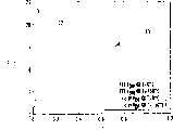
图3是表示电流随MOSFET的反向导电电压VON和MOSFET的体二极管的正向导电电压VDF而变化的曲线图。FIG. 3 is a graph showing current variation with the reverse conduction voltage VON of the MOSFET and the forward conduction voltage VDF of the body diode of the MOSFET.
图4是表示MOSFET的反向导电电压VON和MOSFET的体二极管的正向导电电压VDF随温度而变化的曲线图。FIG. 4 is a graph showing the reverse conduction voltage VON of the MOSFET and the forward conduction voltage VDF of the body diode of the MOSFET as a function of temperature.
图5是对于MOSFET的反向导电电压VON和MOSFET的体二极管的正向导电电压VDF的定值等高线,电流对温度的二维映射图。Fig. 5 is a two-dimensional map of current versus temperature for constant value contours of the reverse conduction voltage VON of the MOSFET and the forward conduction voltage VDF of the body diode of the MOSFET.
图6是图5的二维映射的逆反图。FIG. 6 is an inverse view of the two-dimensional map of FIG. 5 .
图7是表示用于实现本发明的被测电压参数的处理体系结构图。Fig. 7 is a diagram showing the processing architecture of the measured voltage parameters for realizing the present invention.
图8表示图6中的二维映射,其按照MOSFET的反向导电电压VON和MOSFET的体二极管的正向导电电压VDF坐标的正交系,利用16×16网格(512个存储单元)作为标准线性二维LUT。Fig. 8 shows the two-dimensional mapping in Fig.6 , and it uses 16 * 16grids (512 storage cells ) as a standard linear 2D LUT.
图9表示简化复杂性的基于矩形网格的插值方案。Figure 9 shows a rectangular grid based interpolation scheme that reduces complexity.
图10表示图9中的插值方案的半网格转换。FIG. 10 shows the half-grid transformation of the interpolation scheme in FIG. 9 .
图11是时序图,表示对低压侧MOSFET的反向导电电压VON为同步,而对MOSFET的体二极管的正向导电电压VDF为异步的测量方式。FIG. 11 is a timing diagram, which shows that the reverse conduction voltage VON of the low-voltage side MOSFET is synchronous, and the forward conduction voltage VDF of the body diode of the MOSFET is asynchronous.
本发明的详细描述Detailed description of the invention
如上简要所述,本发明利用以下事实,即在降压模式DC-DC电压转换器中用作同步整流器的MOSFET,能够提供关于该MOSFET的温度和电流信息。在标准降压模式DC-DC电压转换器中,低压侧二极管被用作环流通过的元件。就二极管本身而言,其在低压降压模式转换器中,由于二极管的正向电压降而产生了过大的损耗。采用一个MOSFET同步整流器足以减少上述损耗,因为当该MOSFET导通或者激活时,电压降会比二极管的低很多。As briefly stated above, the present invention makes use of the fact that a MOSFET used as a synchronous rectifier in a buck mode DC-DC voltage converter can provide temperature and current information about the MOSFET. In a standard buck-mode DC-DC voltage converter, the low-side diode is used as the circulating current element. As far as the diode itself is concerned, in a low-voltage buck mode converter, excessive losses are generated due to the forward voltage drop of the diode. Using a MOSFET synchronous rectifier is enough to reduce the above losses, because when the MOSFET is turned on or activated, the voltage drop will be much lower than that of the diode.
如图2中用图解法所示,在标准MOSFET(这里指低压侧MOSFET20)内固有的是体二极管40,其与MOSFET的导通路径平行接入。当MOSFET20不导通(非激活),该转换器以异步方式运行。低压侧MOSFET20(不是作为MOSFET,就是作为二极管)的两种导电方式存在既与电流I-电压V特性截然不同的特性,也与之相反的温度相关性。按照本发明,这些对应于两种运行方式的工作情况的差异促进对这两种导电方式的电压(VON,VDF)被转换成唯一的温度和电流特性对的认识。As shown diagrammatically in FIG. 2 , inherent within a standard MOSFET (here low side MOSFET 20 ) is a body diode 40 which is switched in parallel with the conduction path of the MOSFET. When
更特殊的是,“理想”二极管存在并如以下公式(1)定义了I-V特性:More specifically, "ideal" diodes exist and define the I-V characteristic as the following equation (1):
I=KT3exp(-Vg/kT)(exp(V/nkT)-1)I=KT3 exp(-Vg/kT)(exp(V/nkT)-1)
(1) (1)
其中,T是绝对温度,Vg是半导体间隙电压(对于Si为1.1eV),k是玻尔兹曼常数(8.62Ev/°k),V是施加在横过二极管结上的电压,n是理想因子(其中,1n2)。常数K是包括二极管几何效应的值。出于以下论述的目的,该二极管将被假设为于电阻性元件串联,以使整个二极管的关系可以被公式(2)所定义:where T is the absolute temperature, Vg is the semiconductor gap voltage (1.1eV for Si), k is Boltzmann's constant (8.62Ev/°k), V is the voltage applied across the diode junction, and n is the ideal factor (where, 1n2). The constant K is a value including diode geometry effects. For the purposes of the following discussion, the diode will be assumed to be in series with the resistive element so that the overall diode relationship can be defined by equation (2):
I=KT3exp(-Vg/kT)(exp({V-IRDIO(T)}/NKt)-1)I=KT3 exp(-Vg/kT)(exp({V-IRDIO (T)}/NKt)-1)
(2)(2)
其中,电阻元件的阻抗RDIO是温度的函数。为了方便,在以下论述中,该阻抗将被假设为与MOSFET的源漏间导电路径或导通阻抗RDSON成比例。RDSON通常被定义为温度的二阶函数,如公式(3)中所述:Wherein, the resistance RDIO of the resistive element is a function of temperature. For convenience, in the following discussion, this impedance will be assumed to be proportional to the source-drain conduction path or on-resistance RDSON of the MOSFET. RDSON is usually defined as a second-order function of temperature, as described in Equation (3):
RDSON(T)=RDSON(T0){1+(T-T0)+(T-T0)2}RDSON (T)=RDSON (T0 ){1+(TT0 )+(TT0 )2 }
(3)(3)
在上述两种导电关系的基础上,在图3中可以绘制出MOSFET的I-V特性曲线,用于该参数集:K=1e4;n=1.5;RDSON(T0)=5毫欧,RDIO=RDSON/2;T0=25℃;=2.5e-3°/C;且=1.25e-5°/C2。On the basis of the above two conduction relationships, the IV characteristic curve of the MOSFET can be drawn in Fig. 3 for this parameter set: K = 1e4; n = 1.5; RDSON (T0) = 5 milliohms, RDIO = RDSON /2; T0 = 25°C; = 2.5e-3°/C; and = 1.25e-5°/C2 .
如图3中所示,对于温度升高,MOSFET的反向导电特性(VON)经历从曲线31到32缓慢地倾斜下降,以便需要稍大些的电压来完成相同的电流。另一方面,MOSFET的体二极管的正向导电(VDF)需要较低的电压来完成如图中所示在曲线33和34上更高温度的相同电流。As shown in Figure 3, the reverse conduction characteristic (VON ) of the MOSFET undergoes a slow ramp down from
图4绘出了作为温度的函数的电压,其用于每一个反向导电特性(VON)和MOSFET的体二极管的正向导电(VDF)。曲线41和42对应于反向导电特性(VON),而曲线43和44对应于正向导电(VDF)特性。此外,两种特性的工作情况是彼此相反的。Figure 4 plots the voltage as a function of temperature for each of the reverse conduction characteristics (VON ) and the forward conduction (VDF ) of the MOSFET's body diode. Curves 41 and 42 correspond to reverse conduction characteristics (VON ), while curves 43 and 44 correspond to forward conduction characteristics (VDF ). Furthermore, the two features work inversely to each other.
这些电流对电压和电压对温度的差异允许将温度和电流对(T,I)二维映射到MOSFET和二极管的电压降对(VON,VDF)。图5示出在一个方向上的该映射,其以温度和电流T、I为直角坐标,在常数电压VON下的等高线为虚线曲线51,在常数电压VDF下的等高线为实线曲线52。图6示出图5所示曲线的逆映射,其以导电电压VDF、VON为直角坐标,在常数温度T下的等高线为虚线曲线61,在常数电流I下的等高线为实线曲线62。These current versus voltage and voltage versus temperature differences allow two-dimensional mapping of the temperature and current pair (T, I) to the MOSFET and diode voltage drop pair (VON , VDF ). Figure 5 shows this mapping in one direction, with temperature and current T, I as Cartesian coordinates, the contour at constant voltage VON is dashed
虽然图5中温度和电流(0<T<150°/C,1<I<25A)的二维定义域是矩形,当在图6中以VON-VDF坐标观察时可见其经历了几何曲线畸变,但是很容易从数学上估计到,在VDF、VON区域和T、I区域之间有一个清晰的互逆映射。而且,即使本实施例采用特殊函数相关性,但产生该映射所必需的重要方面仍是相反的温度趋势和不同的I-V形式(线性的对指数的)。Although the two-dimensional definition domain of temperature and current (0<T<150°/C, 1<I<25A) in Fig. 5 is a rectangle, when viewed with VON -VDF coordinates in Fig. 6, it can be seen that it has experienced a geometric The curve is distorted, but it is easy to estimate mathematically that there is a clear reciprocal mapping between the VDF , VON regions and the T, I regions. Also, even though the present embodiment employs special functional dependencies, the important aspects necessary to generate this map are the opposite temperature trends and different forms of IV (linear versus exponential).
相对简明地实行使用二维映射((VON,VDF)数据到(T,I)数据的转换),其包括包括对二维——二维查阅表(LUT)的使用,如图7中用图解法所示。如其所示,低压侧MOSFET的反向导电电压VON和MOSFET的体二极管的正向导电电压VDF是通过各自的缓冲放大器70、72,并经多路复用器与AD转换器74连接。然后,将数字化的值供给处理器75,其包含用于将(VON,VDF)数据映射到(T,I)数据的所有LUT。VON、VDF的值被转换成行列地址,其供给两个分别代表温度和电流的存储单元76、77。Relatively concise implementation uses two-dimensional mapping (conversion of (VON , VDF ) data to (T, I) data), which includes the use of two-dimensional - two-dimensional look-up tables (LUTs), as in Fig. 7 Shown graphically. As shown, the reverse conduction voltage VON of the low-side MOSFET and the forward conduction voltage VDF of the body diode of the MOSFET pass through respective buffer amplifiers 70 , 72 and are connected to an AD converter 74 via a multiplexer. The digitized values are then fed to processor 75, which contains all the LUTs used to map (VON , VDF ) data to (T, I) data. The values of VON , VDF are converted into row and column addresses, which are supplied to two storage units 76 , 77 representing temperature and current, respectively.
图8表示使用16×16网格(512个存储单元)的标准线性二维LUT。因为该数据是量子化的,所以在各单元之间需要插值。另外,映射的畸变会导致存储单元超出有利益的T-I定义域。在插值精度和存储尺寸之间折衷是相对简明的。更多存储的提供减少了不使用插值而用网格的误差。另一方面,采用插值能够减少误差,而不用增加存储。Figure 8 shows a standard linear two-dimensional LUT using a 16x16 grid (512 memory cells). Because the data is quantized, interpolation between cells is required. In addition, distortions in the mapping can cause memory cells to fall outside the T-I domain of interest. The tradeoff between interpolation accuracy and storage size is relatively straightforward. The provision of more memory reduces the error of using grids without interpolation. On the other hand, using interpolation can reduce errors without increasing memory.
图9表示简化复杂性的基于矩形网格的插值方案。该插值减少了在四个角上的LUT值:F00、FA0、FAB、F0B,并且产生出由该四角定义的矩形中央的该四角的平均值。这相对简单的插值依旧隐含了合理的计算负荷,但任何人都可以利用电流数字集成电路容易的实现。Figure 9 shows a rectangular grid based interpolation scheme that reduces complexity. This interpolation reduces the LUT values at the four corners: F00 , FA0 , FAB , F0B , and produces an average of the four corners at the center of the rectangle defined by the four corners. This relatively simple interpolation still implies a reasonable computational load, but it can be easily implemented by anyone using current digital integrated circuits.
在本实施例中,最大电流为25A,且RDSON具有1∶1.60的标准化值域(对于1.60的比值,0-150°/C产生0.95-1.51的值域)。如果LUT的安培分辨率要达到要求,那么VON的值域(与I成比例)必须具有1.60×(25或40)个网格点。将此值向上切到最接近的2的幂,并假设在VDF中相等的地址空间产生(64×64×2=213)或者8K的LUT存储地址。进一步的,假设数据宽度8bit(与在T和I上的满刻度分辨率的+/-1%相似),则所必需的LUT存储器为8Kbit。In this example, the maximum current is 25A and RDSON has a normalized range of 1:1.60 (0-150°/C yields a range of 0.95-1.51 for a ratio of 1.60). If the ampere resolution of the LUT is to be adequate, then the range of VON (proportional to I) must have 1.60 × (25 or 40) grid points. Cutting this value up to the nearest power of 2 and assuming an equal address space inVDF yields (64x64x2=213 ) or 8K of LUT storage addresses. Further, assuming a data width of 8bit (similar to +/-1% of full scale resolution on T and I), the necessary LUT memory is 8Kbit.
在存储和插值之间合理的折衷是使用图9所示仅用于半网格点(a=A/2,b=B/2)的插值。图10示出这种简化对于网格的插值,其中A reasonable compromise between storage and interpolation is to use the interpolation shown in Figure 9 for only half the grid points (a=A/2, b=B/2). Figure 10 shows this simplified interpolation for the grid, where
F′nm=Gnm={(2-n)(2-m)F00+(n)(2-m)FA0+(2-n)(m)F0B+nmFAB}/4,F'nm = Gnm = {(2-n)(2-m)F00 +(n)(2-m)FA0 +(2-n)(m)F0B +nmFAB }/4,
其中,n,m={0,1},Among them, n, m={0, 1},
F′00=G00=F00,F′00 =G00 =F00 ,
F′10=G10={F00+FA0}/2,F'10 =G10 ={F00 +FA0 }/2,
F′01=G01={F00+F0B}/2,F'01 =G01 ={F00 +F0B }/2,
F′11=G11={F00+FA0+F0B+FAB}/4.F′11 =G11 ={F00 +FA0 +F0B +FAB }/4.
在此方案中,LUT区域的数目按大约4的倍率增长。该计算的优点在于通过2的幂(位移)来实现所有乘法。In this scheme, the number of LUT regions is increased by a factor of about 4. The advantage of this calculation is that all multiplications are implemented by powers of 2 (shifts).
上述讨论假设该二维映射是已知的,其在本质上具有无限精度,而忽略了两个问题。第一个问题是精确的测量该映射的能力。虽然这对于特效MOSFET来说不是重大问题,但必须注意的是,任何给定的MOSFET在性能上都存在统计分布。除非每个MOSFET都单独特征化,并且相关联的唯一的LUT产生的MOSFET的变化是该映射的误差的主要形式。如果需要比“平均水平”LUT更高的精确度,就必需某些形式的自校准。要达到此目的一种做法是对稳压器的完成进行一种有效期限制造的校准,也就是在转换器中安装完MOSFET以后。如果该程序在已知温度上通过特效MOSFET提供一个已知电流值,那么在映射集合与用于特效MOSFET的映射之间至少存在一个比较点。这有效地产生了用于每个电压对VON和VDF的映射偏移量。The above discussion assumes that the two-dimensional map is known, which has essentially infinite precision, while ignoring two issues. The first problem is the ability to accurately measure the mapping. While this is not a significant issue for special effect MOSFETs, it must be noted that there is a statistical distribution in performance for any given MOSFET. Unless each MOSFET is characterized individually, and the associated unique LUT-generated MOSFET variation is the dominant form of error in this mapping. If higher than "average" LUT accuracy is required, some form of self-calibration is necessary. One way to do this is to perform a valid-life manufacturing calibration on the finish of the regulator, that is, after the MOSFETs are installed in the converter. If the program provides a known value of current through the specific effect MOSFET at a known temperature, then there is at least one point of comparison between the set of maps and the map for the specific effect MOSFET. This effectively produces a mapping offset for each voltage pair VON and VDF .
获得该电压对的测量,对于导出低压侧MOSFET的反向导电电压VON的值是同步的,而对于导出MOSFET的体二极管的正向导电电压VDF的值是异步的。图11图解说明了这些测量可以实现的方式。如图所示VON在第一个周期111内被测量,其用作监测低压侧MOSFET的RDSON的系统标准,以确定电流。甚至在正常的同步操作期间,在每个转换跃迁中都有简短的时间间隔,期间MOSFET的体二极管是导通的,但由于功率损耗,要尽可能使保持导通的时间短。结果,从时间安排的角度考虑和从噪声(在急剧变化之后的上升)的观点来看,在该时间间隔中测量VDF值是不实际的。The measurement of this voltage pair is obtained synchronously for deriving the value of the reverse conduction voltage VON of the low-side MOSFET and asynchronously for deriving the value of the forward conduction voltage VDF of the body diode of the MOSFET. Figure 11 illustrates the way these measurements can be achieved. VON is measured during the first cycle 111 as shown, which is used as a system criterion for monitoring RDSON of the low side MOSFET to determine current. Even during normal synchronous operation, there are brief intervals in each switching transition during which the body diode of the MOSFET is conducting, but due to power losses, it is kept on for as short a time as possible. As a result, it is impractical to measure the VDF value in this time interval from a timing point of view and from a noise (rising after a sharp change) point of view.
第二周期112代表MOSFET没有接通的异步转换周期,并且导电仅通过MOSFET的体二极管发生。因而在此周期内测量到VDF。因为任何温度变化都是相对平缓的,并且仅需要不经常的采样,所以能够相对不经常的测量到VDF。在1MHz的转换速率和1%的VDF测量比率之处,温度能够在每100微秒被测,这仍是依据转换器的热时间常数的很好的比率。这百分之一的VDF周期使系统由于异步操作而产生效率的损失保持在非常小的水平。在所有VDF的测量之间,能够有效的将温度当作常数对待,并且能够将VON的值施加在电流监测上,用于标准RDSON监测方案中。当然,该MOSFET可以在异步VDF测量之后立即接通,所以用于整个切换时间的异步操作不必撤消。The second period 112 represents an asynchronous switching period in which the MOSFET is not turned on, and conduction occurs only through the body diode of the MOSFET. Thus VDF is measured during this period. Because any temperature changes are relatively gradual and require only infrequent sampling,VDF can be measured relatively infrequently. At a slew rate of 1 MHz and a VDF measurement rate of 1%, the temperature can be measured every 100 microseconds, which is still a good rate in terms of the thermal time constant of the converter. This one percent VDF period keeps the loss of system efficiency due to asynchronous operation at a very small level. Between all VDF measurements, the temperature can be effectively treated as a constant, and the value of VON can be applied to the current monitor for the standard RDSON monitoring scheme. Of course, this MOSFET can be turned on immediately after the asynchronous VDF measurement, so the asynchronous operation for the entire switching time does not have to be undone.
要注意的是,前面的描述隐含零电感滞流。由于电感滞流增长(对应于在所有转换之间的VSW的斜坡),所以有出现误差的可能。这可以通过使用经验偏移量或者在一个周期内实施多次测量来调节,以建立斜坡和因而外插调整过的电压值。接着,这些调整过的电压值将作为输入供给上述的二维映射方案。Note that the preceding description implies zero-inductance hysteresis. There is potential for error due to the hysteretic growth of the inductor (corresponding to the ramp of VSW between all transitions). This can be adjusted by using an empirical offset or by performing multiple measurements within a cycle to establish the ramp and thus extrapolate the adjusted voltage value. Then, these adjusted voltage values will be fed as input to the 2D mapping scheme described above.
虽然根据本发明的一个实施例已显示和描述了I,但是作为本领域技术人员,应该理解相同的I不受限于此外的各种数量变化和变型。因此I不会受限于在这里显示和描述的细节,而要覆盖所有的那些对于本领域普通技术人员显而易见的变化和变型。Although I has been shown and described according to one embodiment of the present invention, it should be understood by those skilled in the art that the same I is not limited to other various changes and modifications. I therefore do not intend to be limited to the details shown and described herein, but to cover all such changes and modifications as would be apparent to one of ordinary skill in the art.
Claims (15)
Translated fromChineseApplications Claiming Priority (2)
| Application Number | Priority Date | Filing Date | Title |
|---|---|---|---|
| US10/691,370 | 2003-10-22 | ||
| US10/691,370US6946897B2 (en) | 2003-10-22 | 2003-10-22 | Technique for measuring temperature and current via a MOSFET of a synchronous buck voltage converter |
Publications (2)
| Publication Number | Publication Date |
|---|---|
| CN1624442Atrue CN1624442A (en) | 2005-06-08 |
| CN100382423C CN100382423C (en) | 2008-04-16 |
Family
ID=34521865
Family Applications (1)
| Application Number | Title | Priority Date | Filing Date |
|---|---|---|---|
| CNB2004101038958AExpired - Fee RelatedCN100382423C (en) | 2003-10-22 | 2004-10-22 | Techniques for Measuring Temperature and Current Through a MOSFET in a Synchronous Buck Converter |
Country Status (3)
| Country | Link |
|---|---|
| US (1) | US6946897B2 (en) |
| CN (1) | CN100382423C (en) |
| TW (1) | TWI269515B (en) |
Cited By (5)
| Publication number | Priority date | Publication date | Assignee | Title |
|---|---|---|---|---|
| CN101470142B (en)* | 2007-12-27 | 2011-03-09 | 英业达股份有限公司 | Overcurrent detection circuit, step-down converter and overcurrent detection method |
| CN101118188B (en)* | 2006-08-02 | 2012-03-07 | 瑞萨电子株式会社 | Temperature detection circuit and semiconductor device |
| CN101667776B (en)* | 2008-07-23 | 2013-10-23 | 英特赛尔美国股份有限公司 | System and method for reducing voltage overshoot during load release in a buck regulator |
| CN104113186A (en)* | 2013-04-18 | 2014-10-22 | 百富(澳门离岸商业服务)有限公司 | Switch-mode Power Supply With Temperature And Current Sharing |
| TWI491858B (en)* | 2013-03-15 | 2015-07-11 | Richtek Technology Corp | Temperature determination circuit and method thereof |
Families Citing this family (17)
| Publication number | Priority date | Publication date | Assignee | Title |
|---|---|---|---|---|
| US7246330B2 (en)* | 2004-10-12 | 2007-07-17 | Texas Instruments Incorporated | Apparatus and method for detecting body diode conduction in a semiconductor device |
| DE102006001874B4 (en)* | 2006-01-13 | 2012-05-24 | Infineon Technologies Ag | Method and device for current and temperature measurement in a power electronic circuit |
| CN102486414B (en)* | 2010-12-01 | 2015-10-28 | 上海复旦微电子股份有限公司 | Temperature sensor circuit |
| US8847575B2 (en)* | 2011-10-14 | 2014-09-30 | Infineon Technologies Ag | Circuit arrangement |
| EP2760093B1 (en)* | 2013-01-29 | 2017-04-12 | Delphi Technologies, Inc. | Power switch fault detection system |
| US9557351B2 (en)* | 2013-12-18 | 2017-01-31 | Deere & Company | Sensorless current sensing methods for power electronic converters |
| US9829387B2 (en)* | 2014-10-28 | 2017-11-28 | Infineon Technologies Austria Ag | System and method for temperature sensing |
| US10191021B2 (en) | 2015-02-27 | 2019-01-29 | Deere & Company | Method for estimating a temperature of a transistor |
| US20190079121A1 (en)* | 2015-10-20 | 2019-03-14 | Telefonaktiebolaget Lm Ericsson (Publ) | Estimating a current in an smps |
| US10338669B2 (en) | 2015-10-27 | 2019-07-02 | Dell Products, L.P. | Current sense accuracy improvement for MOSFET RDS (on) sense based voltage regulator by adaptive temperature compensation |
| WO2018005727A1 (en)* | 2016-06-30 | 2018-01-04 | Witricity Corporation | Diode conduction sensor |
| CN107783031B (en)* | 2016-08-30 | 2020-02-21 | 比亚迪股份有限公司 | Fault detection device and method for high voltage system and its power switch module |
| US10116212B2 (en) | 2017-03-13 | 2018-10-30 | Dell Products, L.P. | Voltage regulation based on current sensing in MOSFET drain-to-source resistance in on-state RDS(ON) |
| US11443175B2 (en) | 2018-07-11 | 2022-09-13 | Silicon Storage Technology, Inc. | Compensation for reference transistors and memory cells in analog neuro memory in deep learning artificial neural network |
| US10615737B1 (en) | 2018-09-24 | 2020-04-07 | Nxp Usa, Inc. | System and method of estimating temperature of a power switch of a power converter without a dedicated sensor |
| DE102020120814A1 (en) | 2020-08-06 | 2022-02-10 | Seg Automotive Germany Gmbh | Method for checking a fast de-excitation path of an excitation circuit and corresponding excitation circuit |
| JP2023006250A (en)* | 2021-06-30 | 2023-01-18 | 富士電機株式会社 | Integrated circuit, and power module |
Family Cites Families (6)
| Publication number | Priority date | Publication date | Assignee | Title |
|---|---|---|---|---|
| US3947706A (en)* | 1975-04-30 | 1976-03-30 | The United States Of America As Represented By The Secretary Of The Navy | Voltage and temperature compensated linear rectifier |
| JP3175959B2 (en)* | 1991-11-12 | 2001-06-11 | 株式会社東芝 | Simulation method of semiconductor integrated circuit |
| JPH07234162A (en)* | 1994-02-24 | 1995-09-05 | Toshiba Corp | Power converter temperature detection device |
| US5764032A (en)* | 1997-03-06 | 1998-06-09 | Maxim Integrated Products, Inc. | Multiple battery switchover circuits |
| US6160441A (en)* | 1998-10-30 | 2000-12-12 | Volterra Semiconductor Corporation | Sensors for measuring current passing through a load |
| US6765372B2 (en)* | 2001-12-14 | 2004-07-20 | Intersil Americas Inc. | Programmable current-sensing circuit providing continuous temperature compensation for DC-DC Converter |
- 2003
- 2003-10-22USUS10/691,370patent/US6946897B2/ennot_activeExpired - Fee Related
- 2004
- 2004-10-13TWTW093130988Apatent/TWI269515B/ennot_activeIP Right Cessation
- 2004-10-22CNCNB2004101038958Apatent/CN100382423C/ennot_activeExpired - Fee Related
Cited By (7)
| Publication number | Priority date | Publication date | Assignee | Title |
|---|---|---|---|---|
| CN101118188B (en)* | 2006-08-02 | 2012-03-07 | 瑞萨电子株式会社 | Temperature detection circuit and semiconductor device |
| CN101470142B (en)* | 2007-12-27 | 2011-03-09 | 英业达股份有限公司 | Overcurrent detection circuit, step-down converter and overcurrent detection method |
| CN101667776B (en)* | 2008-07-23 | 2013-10-23 | 英特赛尔美国股份有限公司 | System and method for reducing voltage overshoot during load release in a buck regulator |
| TWI491858B (en)* | 2013-03-15 | 2015-07-11 | Richtek Technology Corp | Temperature determination circuit and method thereof |
| US9568376B2 (en) | 2013-03-15 | 2017-02-14 | Richtek Technology Corp | Temperature detecting circuit and method thereof |
| CN104113186A (en)* | 2013-04-18 | 2014-10-22 | 百富(澳门离岸商业服务)有限公司 | Switch-mode Power Supply With Temperature And Current Sharing |
| CN104113186B (en)* | 2013-04-18 | 2017-04-12 | 百富(澳门离岸商业服务)有限公司 | Switch-mode Power Supply With Temperature And Current Sharing |
Also Published As
| Publication number | Publication date |
|---|---|
| TWI269515B (en) | 2006-12-21 |
| US20050088863A1 (en) | 2005-04-28 |
| TW200529539A (en) | 2005-09-01 |
| CN100382423C (en) | 2008-04-16 |
| US6946897B2 (en) | 2005-09-20 |
Similar Documents
| Publication | Publication Date | Title |
|---|---|---|
| CN100382423C (en) | Techniques for Measuring Temperature and Current Through a MOSFET in a Synchronous Buck Converter | |
| Glaser et al. | Direct comparison of silicon and silicon carbide power transistors in high-frequency hard-switched applications | |
| Ye et al. | A resonant switched capacitor based 4-to-1 bus converter achieving 2180 W/in 3 power density and 98.9% peak efficiency | |
| Seo et al. | Dual inductor hybrid converter for point-of-load voltage regulator modules | |
| Hou et al. | A multivariable turn-on/turn-off switching loss scaling approach for high-voltage GaN HEMTs in a hard-switching half-bridge configuration | |
| Alharbi et al. | Experimental evaluation of medium-voltage cascode gallium nitride (GaN) devices for bidirectional DC-DC converters | |
| Cougo et al. | Accurate switching energy estimation of wide bandgap devices used in converters for aircraft applications | |
| Lukić et al. | Sensorless self-tuning digital CPM controller with multiple parameter estimation and thermal stress equalization | |
| CN112840544A (en) | Circuit and method for measuring output current of switched capacitor regulator | |
| Tiwari et al. | Design of low inductive busbar for fast switching SiC modules verified by 3D FEM calculations and laboratory measurements | |
| Brooks et al. | Low-inductance asymmetrical hybrid gan hemt switching cell design for the fcml converter in high step-down applications | |
| Biglarbegian et al. | Characterization of SenseGaN current-mirroring for power GaN with the virtual grounding in a boost converter | |
| Roy et al. | Challenges and Implementation of Online In Situ R DSON Measurement in a Three-Phase Inverter | |
| Saglam et al. | A comparison of gan-based cascode and e-mode hemts using bridgeless totem pole pfc | |
| Koch et al. | Gate driver concept for parallel operation of low-voltage high-current gan power transistors for mild-hybrid applications | |
| Christen et al. | Design and optimization of a wide dynamic range Programmable Power Supply for data center applications | |
| Ren et al. | Parameter identification based on linear model for buck converters | |
| Sartori et al. | Power density comparative analysis concerning to three transistor technologies applied to a CCM PFC BOOST converter using optimization techniques | |
| Ebersberger et al. | Dynamic characterization of a sic-mosfet half bridge in hard-and soft-switching and investigation of current sensing technologies | |
| Yerra et al. | Simplified gate driving strategy for GaN-Based multi-level buck converters operating at MHz switching frequencies | |
| Vethanayagam et al. | Loss Analysis of Conventional and Three Level Boost DC-DC Converters employed for MPPT in PV Systems | |
| Chen et al. | Switching Performance Comparison of Low-Voltage GaN and Si Devices | |
| Sawant et al. | Design of High-Frequency, High-Power Class $\Phi _ {2} $ Inverter Through On-Resistance and Output Capacitance Loss Reduction in 650 V Parallel eGaN Transistors for Optimal Thermal Performance | |
| Tang et al. | A 2MHz Constant-Frequency AOT V 2 Buck Converter with Adaptive Dead Time Control for Data Centers | |
| CN102667659B (en) | For obtaining the method for the information of the determination of enable power supply characteristic |
Legal Events
| Date | Code | Title | Description |
|---|---|---|---|
| C06 | Publication | ||
| PB01 | Publication | ||
| C10 | Entry into substantive examination | ||
| SE01 | Entry into force of request for substantive examination | ||
| C14 | Grant of patent or utility model | ||
| GR01 | Patent grant | ||
| C19 | Lapse of patent right due to non-payment of the annual fee | ||
| CF01 | Termination of patent right due to non-payment of annual fee |