CN1617531A - TDS-OFDM receiver time-varying channel estimation and equalization method and system - Google Patents
TDS-OFDM receiver time-varying channel estimation and equalization method and systemDownload PDFInfo
- Publication number
- CN1617531A CN1617531ACN 200410009944CN200410009944ACN1617531ACN 1617531 ACN1617531 ACN 1617531ACN 200410009944CN200410009944CN 200410009944CN 200410009944 ACN200410009944 ACN 200410009944ACN 1617531 ACN1617531 ACN 1617531A
- Authority
- CN
- China
- Prior art keywords
- circuit
- output
- dft
- input
- channel
- Prior art date
- Legal status (The legal status is an assumption and is not a legal conclusion. Google has not performed a legal analysis and makes no representation as to the accuracy of the status listed.)
- Granted
Links
Images


Landscapes
- Cable Transmission Systems, Equalization Of Radio And Reduction Of Echo (AREA)
Abstract
Description
Translated fromChinese技术领域technical field
本发明属于数字信息传输技术领域,特别涉及一种时域同步正交频分复用(Time DomainSynchronous OFDM,TDS-OFDM)数字电视接收机的时变信道估计与均衡方法及其系统。The invention belongs to the technical field of digital information transmission, and in particular relates to a time-varying channel estimation and equalization method and a system thereof for a Time Domain Synchronous OFDM (TDS-OFDM) digital television receiver.
背景技术Background technique
地面无线电视广播传输信道中(主要是VHF和UHF频段)存在着各种多径和衰落现象,造成了静态/动态多径干扰,是一个时变的频率选择性衰落信道。在移动接收环境下,会产生多普勒频移。如果发送一个单频的信号,接收到的信号将是一个以发送的频率为中心,以最大多普勒频移为带宽的限带信号,接收信号的功率谱一般为Jake的模型,可以表示为:Various multipath and fading phenomena exist in the transmission channel of terrestrial wireless TV broadcasting (mainly VHF and UHF frequency bands), which cause static/dynamic multipath interference, and it is a time-varying frequency selective fading channel. In a mobile receiving environment, Doppler frequency shift will occur. If a single-frequency signal is sent, the received signal will be a band-limited signal centered on the transmitted frequency and with the maximum Doppler shift as the bandwidth. The power spectrum of the received signal is generally Jake’s model, which can be expressed as :

在上式中,wd=2πTsfd。其中Ts为符号间隔,fd为最大多普勒频移。fd由载波频率fc和移动速度v决定:In the above formula, wd =2πTs fd . Where Ts is the symbol interval and fd is the maximum Doppler frequency shift. fd is determined by the carrier frequency fc and the moving speed v:
其中,c为光速。接收信号在移动接收环境下产生的频谱扩展,对采用相干解调的通信系统会产生恶劣影响,使系统性能下降。尤其对由许多正交的子载波组成的OFDM信号来说,子信道带宽比整个带宽小得多,多普勒频移引入的子载波间干扰(ICI)将破坏OFDM信号不同子载波间的正交性,一个小的多普勒频移都会导致较大的信噪比损失,从而要求我们要有高性能的时变信道估计和均衡方法,同时还必须简化接收机的复杂度。where c is the speed of light. The spectrum expansion of the received signal in the mobile receiving environment will have a bad impact on the communication system using coherent demodulation, which will degrade the system performance. Especially for OFDM signals composed of many orthogonal sub-carriers, the sub-channel bandwidth is much smaller than the entire bandwidth, and the inter-sub-carrier interference (ICI) introduced by Doppler frequency shift will destroy the regularity between different sub-carriers of OFDM signals. A small Doppler frequency shift will lead to a large SNR loss, which requires us to have a high-performance time-varying channel estimation and equalization method, and must also simplify the complexity of the receiver.
清华大学提出的地面数字多媒体电视广播(Digital MultimediaTV Broadcasting-Terrestrial,DMB-T)方案的目的是提供一种数字信息传输方法,采用了时域同步正交频分复用(Time Domain Synchronous OFDM,TDS-OFDM)调制技术,关于DMB-T、TDS-OFDM的相关情况详见授权号为00123597.4名为“地面数字多媒体电视广播系统”、授权号为01115520.5名为“时域同步正交频分复用调制方法”以及授权号为01124144.6名为“正交频分复用调制系统中保护间隔的填充方法”等清华大学申请的中国发明专利。The purpose of the Digital MultimediaTV Broadcasting-Terrestrial (DMB-T) program proposed by Tsinghua University is to provide a digital information transmission method, which uses Time Domain Synchronous Orthogonal Frequency Division Multiplexing (Time Domain Synchronous OFDM, TDS -OFDM) modulation technology. For details about DMB-T and TDS-OFDM, please refer to the authorization number 00123597.4 entitled "Terrestrial Digital Multimedia Television Broadcasting System" and the authorization number 01115520.5 entitled "Time Domain Synchronous Orthogonal Frequency Division Multiplexing Modulation method" and a Chinese invention patent applied by Tsinghua University with the authorization number 01124144.6 entitled "Filling method of guard interval in orthogonal frequency division multiplexing modulation system".
DMB-T系统的结构具有分层的帧结构,其物理信道帧结构如图1所示。帧群定义为一群信号帧,其第一帧定义为帧群头(控制帧)。超帧定义为一组帧群。帧结构的顶层称为日帧(CalendarDay Frame,CDF)。物理信道是周期的,并且和绝对时间同步。信号帧是DMB-T系统帧结构的基本单元。一个信号帧由帧同步和帧体两部分组成(见图1)。帧同步和帧体的基带符号率相同,规定为7.56MSps。帧同步由PN序列循环扩展生成,PN序列作为同步,可变保护间隔(填充PN序列、循环前缀或零值),长度不超过IDFT块长度的1/4。PN序列定义为一个8阶m序列,其特征多项式定义为x8+x6+x5+x+1,初始条件模板将确定所生成m序列的相位。对于一个特定的信号帧,它的信号帧号决定PN序列的初始条件。经“0”到“+1”值及“1”到“-1”值的映射后,PN序列变换为非归零的二进制信号。The structure of the DMB-T system has a layered frame structure, and its physical channel frame structure is shown in Figure 1 . A frame group is defined as a group of signal frames, the first frame of which is defined as a frame group header (control frame). A superframe is defined as a set of frame groups. The top layer of the frame structure is called a calendar day frame (CalendarDay Frame, CDF). Physical channels are periodic and synchronized with absolute time. The signal frame is the basic unit of the DMB-T system frame structure. A signal frame is composed of frame synchronization and frame body (see Figure 1). The baseband symbol rate of frame synchronization and frame body is the same, which is specified as 7.56MSps. Frame synchronization is generated by cyclic extension of PN sequence, PN sequence is used as synchronization, variable guard interval (filling PN sequence, cyclic prefix or zero value), and the length does not exceed 1/4 of the IDFT block length. The PN sequence is defined as an 8th-order m-sequence, and its characteristic polynomial is defined as x8 +x6 +x5 +x+1, and the initial condition template will determine the phase of the generated m-sequence. For a specific signal frame, its signal frame number determines the initial condition of the PN sequence. After mapping from "0" to "+1" and "1" to "-1", the PN sequence is converted into a non-return-to-zero binary signal.
一个帧体的基带信号是一个正交频分复用(OFDM)块。一个OFDM块进一步分成一个保护间隔和一个离散傅立叶逆变换(IDFT)块。对于TDS-OFDM来说,PN同步序列既作为帧同步,又作为OFDM的保护间隔,而帧体作为DFT块,如图1所示。由于PN序列与DFT块的正交时分复用,而且PN序列对于接收端来说是已知序列,因此,PN序列和DFT块在接收端是可以被分开的。The baseband signal of a frame body is an Orthogonal Frequency Division Multiplexing (OFDM) block. An OFDM block is further divided into a guard interval and an inverse discrete Fourier transform (IDFT) block. For TDS-OFDM, the PN synchronization sequence is not only used as frame synchronization, but also as a guard interval of OFDM, and the frame body is used as a DFT block, as shown in Figure 1. Since the PN sequence and the DFT block are orthogonally time-division multiplexed, and the PN sequence is a known sequence for the receiving end, the PN sequence and the DFT block can be separated at the receiving end.
清华大学提出了在DMB-TOFDM系统框架上,不考虑信道在一个OFDM块内变化的信道估计和均衡方法,假定信道在一个OFDM块内保持恒定,采用PN码时域相关方法进行信道估计,并通过频域的简单除法运算来进行信道均衡,如图3所示。简要介绍如下:Tsinghua University proposed a channel estimation and equalization method based on the DMB-TOFDM system framework, which does not consider channel changes within an OFDM block. Assuming that the channel remains constant within an OFDM block, the PN code time-domain correlation method is used for channel estimation, and Channel equalization is performed through a simple division operation in the frequency domain, as shown in FIG. 3 . A brief introduction is as follows:
不考虑数据对同步头的干扰,接收到的第n个OFDM块的PN码帧同步(帧头)r(n,m)可表示为:Regardless of the interference of data on the synchronization header, the received PN code frame synchronization (frame header) r(n, m) of the nth OFDM block can be expressed as:
式中的hc(n,l)为信道在第n个OFDM块内的时域冲激响应(l代表信道路径号,L为路径数),z(n,m)为高斯白噪声,c(m)为使用的PN序列,它具有良好的相关特性,其归一化相关函数ρ(m)可表示为:hc (n, l) in the formula is the time-domain impulse response of the channel in the nth OFDM block (l represents the channel path number, L is the path number), z (n, m) is Gaussian white noise, c (m) is the PN sequence used, which has good correlation characteristics, and its normalized correlation function ρ(m) can be expressed as:

其中m1、m表示序号,Q为PN序列的长度,*号表示共轭运算符。Among them, m1 and m represent serial numbers, Q is the length of PN sequence, and * represents a conjugate operator.
经过PN码时域相关即可得到信道的时域冲激响应的粗估计:A rough estimate of the time-domain impulse response of the channel can be obtained through the time-domain correlation of the PN code:
其中h(n,l)为理想的时域冲激响应,zc(n,l)为高斯白噪声。Among them, h(n, l) is the ideal impulse response in time domain, and zc (n, l) is Gaussian white noise.
得到的粗估计中的小电平值被丢弃,得到第n个OFDM块的信道时域冲激响应的估计因为存在白噪声和多径时,这些小电平已经不可靠了,门限的选择可视应用所要求的不同的抗噪声和分辨多径的灵敏性来决定。get a rough estimate The small level values in are discarded to obtain the estimate of the channel time-domain impulse response of the nth OFDM block Because these small levels are unreliable in the presence of white noise and multipath, the choice of threshold can be determined by the different anti-noise and sensitivity to resolve multipath required by the application.
假设信道的第一条径为主径,那么把经过N点离散傅立叶变换(DFT)处理得到各个OFDM子载波频率响应的估计Assuming that the first path of the channel is the main path, then put The frequency response of each OFDM subcarrier is estimated by N-point discrete Fourier transform (DFT) processing
从帧体中去除PN序列的同步头干扰,并构造帧头与信道的循环卷积,再对帧体进行离散傅立叶变换,得到帧体的频域数据Y(n,k);把信号帧的频域数据Y(n,k)和得到的频域响应估计相除,得到信道均衡后的数据信号
然而,上述方法忽略了信道在一个OFDM块内的变化,当信道变化较慢时是一个简单实用的方法。但在移动接收环境下,简单的假定信道在一个OFDM块内恒定不变,必然不能准确地估计信道,从而带来性能的损失,当接收机的移动速度较高时,信道在一个OFDM块内的变化不能被忽略,否则将会严重影响接收机的性能。为此,本发明在TDS-OFDM的系统框架上,突破了原有的假定OFDM块内信道不变的假设,假定信道在一个OFDM块内为线性变化,提出了TDS-OFDM接收机的时变信道估计与均衡方法及其系统,即基于PN码时域相关的OFDM块内线性内插信道估计方法和对具有子载波间干扰(ICI)的均衡矩阵求逆进行有限项幂级数展开的简化均衡方法。一方面大大提高了TDS-OFDM接收机在时变信道环境下的接收性能,另一方面也做了均衡器复杂度的简化,保证了接收机具有较低的复杂度。However, the above method ignores the change of the channel within one OFDM block, and it is a simple and practical method when the channel changes slowly. However, in the mobile receiving environment, simply assuming that the channel is constant within an OFDM block, it is inevitable that the channel cannot be accurately estimated, resulting in performance loss. When the mobile speed of the receiver is high, the channel is within an OFDM block. The change of can not be ignored, otherwise it will seriously affect the performance of the receiver. For this reason, on the system frame of TDS-OFDM, the present invention breaks through the original assumption that the channel in the OFDM block is constant, assumes that the channel changes linearly in an OFDM block, and proposes a time-varying Channel estimation and equalization method and its system, that is, OFDM intra-block linear interpolation channel estimation method based on PN code time domain correlation and simplification of finite term power series expansion for equalization matrix inversion with intercarrier interference (ICI) balanced approach. On the one hand, it greatly improves the receiving performance of the TDS-OFDM receiver in the time-varying channel environment, and on the other hand, it also simplifies the complexity of the equalizer to ensure that the receiver has a lower complexity.
发明内容Contents of the invention
地面无线电视广播在移动接收环境下,是一个时变的频率选择性衰落信道,本发明提出的时变信道估计和均衡方法假设信道在一个OFDM块内呈线性变化,这在一般的移动接收时能与真实的信道变化非常吻合。但由于本发明考虑了信道在一个OFDM块内的变化,在进行均衡时就不能用简单的除法来实现。本发明在TDS-OFDM的系统框架上,突破了原有的假定OFDM块内信道不变的假设,假定信道在一个OFDM块内为线性变化,提出了TDS-OFDM接收机的时变信道估计与均衡方法及其系统,即基于PN码时域相关的OFDM块内线性内插信道估计方法和对具有子载波间干扰(ICI)的均衡矩阵求逆进行有限项幂级数展开的简化均衡方法。本发明提出的信道估计和均衡方法能够适应移动接收时的信道快速变化,对信道变化有较强的鲁棒性,相对于不考虑信道在一个OFDM块内变化的方法有较大的性能改进,尤其是在信道变化较快的环境下。此外,本发明提出的低复杂度的简化均衡算法实现简单,便于应用。Terrestrial wireless TV broadcasting is a time-varying frequency-selective fading channel in a mobile receiving environment. The time-varying channel estimation and equalization method proposed in the present invention assumes that the channel changes linearly in an OFDM block, which is a common problem in general mobile receiving. Can closely match the real channel variation. But because the present invention considers the change of the channel in one OFDM block, it cannot be realized by simple division when performing equalization. On the TDS-OFDM system framework, the present invention breaks through the original assumption that the channel in an OFDM block is constant, assumes that the channel changes linearly in an OFDM block, and proposes a time-varying channel estimation and An equalization method and its system, that is, an OFDM intra-block linear interpolation channel estimation method based on PN code time domain correlation and a simplified equalization method for inverting an equalization matrix with intercarrier interference (ICI) and performing finite term power series expansion. The channel estimation and equalization method proposed by the present invention can adapt to the rapid channel changes during mobile reception, has strong robustness to channel changes, and has greater performance improvement than the method that does not consider channel changes within an OFDM block. Especially in an environment where the channel changes rapidly. In addition, the low-complexity simplified equalization algorithm proposed by the present invention is simple to implement and easy to apply.
本发明提出的TDS-OFDM接收机的时变信道估计和均衡方法,其特征在于,它是在数字信号处理系统中依次按以下步骤实现的:The time-varying channel estimation and equalization method of the TDS-OFDM receiver that the present invention proposes is characterized in that, it is realized in the following steps successively in the digital signal processing system:
步骤1)分离器把接收到的时域同步正交频分复用即TDS-OFDM的信号帧分解为PN码帧同步即帧头部分和DFT数据即帧体两部分;Step 1) the splitter decomposes the received time domain synchronous orthogonal frequency division multiplexing (TDS-OFDM) signal frame into PN code frame synchronization, i.e. frame header part and DFT data, i.e. frame body two parts;
步骤2)去除PN干扰电路电路从帧体中去除PN序列的同步头干扰,构造帧头与信道的循环卷积;Step 2) removing the PN interference circuit The circuit removes the synchronization head interference of the PN sequence from the frame body, and constructs the circular convolution of the frame head and the channel;
步骤3)第一DFT电路对帧体进行离散傅立叶变换,得到帧体的频域数据Y(n,k),DFT为离散傅立叶变换;Step 3) The first DFT circuit carries out discrete Fourier transform to the frame body to obtain the frequency domain data Y(n, k) of the frame body, and DFT is a discrete Fourier transform;
步骤4)设定:信道在PN头处不变,相关器用本地PN码对接收到的PN码作时域相关得到信道在第n个OFDM块的PN头时刻的信道冲激响应估计,即N0为PN头在每个OFDM块内的相对位置编号,l为路径号,所述的
其中,c(m)为使用的PN序列的第m个符号,r(n,N0,m)为接收到的在第n个OFDM块内的PN码帧同步中的第m个符号,Q为PN序列的长度,*号表示共轭运算符;Among them, c(m) is the mth symbol of the PN sequence used, r(n, N0 , m) is the mth symbol in the received PN code frame synchronization in the nth OFDM block, Q is the length of the PN sequence, and the * symbol represents the conjugate operator;
步骤5)第二DFT电路通过对步骤4)得到的所述信道冲激响应进行傅立叶变换得到信道在第n个OFDM块的PN头时刻的频率响应估计即Step 5) The second DFT circuit obtains the frequency response estimate of the channel at the PN head moment of the nth OFDM block by performing Fourier transform on the channel impulse response obtained in step 4), namely
步骤6)延时和数字逻辑电路对步骤5)得到的频率响应估计进行延时和四则逻辑运算得到第n个OFDM块与第n-1个OFDM块的PN头时刻的频率响应估计的平均值即与差值的一半即以及与

步骤7)另一个数字逻辑电路用步骤6)得到的上述对OFDM块内频率响应估计作线性插值得到第n个OFDM块内的第i个数据时刻、第k个子载波频率上的信道频率响应估计即作为输出,用下式表示:Step 7) Another digital logic circuit uses the above-mentioned obtained in step 6) Linear interpolation is performed on the frequency response estimate in the OFDM block to obtain the channel frequency response estimate at the i-th data moment and the k-th subcarrier frequency in the n-th OFDM block. As an output, it is represented by the following formula:
其中,in,
N为DFT的长度,Nf为整个OFDM块的长度,即PN头的长度与DFT的长度之和;N is the length of the DFT, and Nf is the length of the entire OFDM block, that is, the sum of the length of the PN header and the length of the DFT;
步骤8)设定:信道在一个OFDM块内线性变化,则根据下述对具有子载波间干扰的均衡矩阵求逆进行有限项幂级数展开的简化均衡方法得到第n个OFDM块内第k个子载波频率上的发送数据的近似估计值,用Z(n,k)表示:Step 8) setting: the channel changes linearly in an OFDM block, then obtain the kth in the nth OFDM block according to the following simplified equalization method for inverting the equalization matrix with intersubcarrier interference and carrying out finite term power series expansion The approximate estimated value of the transmitted data on subcarrier frequencies is represented by Z(n, k):
其中,
ai,i=1,2,...,N由步骤7)得到; ai, i=1, 2, ..., N is obtained by step 7);
T(n)是用含有依次串联的乘法器1、IDFT电路、另一输入为ai的乘法器2、第三DFT电路的T-process电路对从步骤6)得到的
Z(n,k)是由一个除法器2对从步骤8)得到的φ(n,k)、步骤6)得到的取商后得到的输出。Z(n,k) is obtained by a
根据上述的TDS-OFDM接收机的时变信道估计与均衡方法而提出的TDS-OFDM接收机的时变信道估计与均衡系统,其特征在于,它含有:The time-varying channel estimation and equalization system of the TDS-OFDM receiver proposed according to the time-varying channel estimation and equalization method of the above-mentioned TDS-OFDM receiver is characterized in that it contains:
分离器,它有一个OFDM信号输入端;a splitter having an OFDM signal input;
去除PN干扰电路,它的输入端与分离器的DFT数据输出端相连;Remove the PN interference circuit, its input end is connected with the DFT data output end of the splitter;
第一DFT电路,它的输入端与上述的去除PN干扰电路的输出端相连;The first DFT circuit, its input end is connected with the output end of above-mentioned removing PN interference circuit;
本地PN码生成电路,它的输出与PN码时域相关器的输入相连;Local PN code generation circuit, its output is connected with the input of PN code time domain correlator;
PN码时域相关器,它的另一个输入端与上述分离器的帧PN同步码输出端相连;第二DFT电路,它有一个长度为N的时域信道估计序列即信号的输入端,它的输出为与延时电路相连;PN code time domain correlator, its other input end is connected with the frame PN synchronous code output end of above-mentioned splitter; The second DFT circuit, it has a time domain channel estimation sequence that length is N namely signal input, its output is Connected with the delay circuit;
延时电路和数字逻辑电路:Delay circuits and digital logic circuits:
延时电路的输入与上述第二DFT电路的输出端相连;The input of the delay circuit is connected with the output end of the above-mentioned second DFT circuit;
数字逻辑电路,它含有两条串联支路,第一条依次用加法器2和乘法器3串联而成;第二条依次由减法器1、乘法器4、乘法器5和减法器2串联而成;所述的加法器2、减法器1都与上述第二DFT电路的


T-process电路,一共有M个,一般取M=1,若M>1,则T-process电路间为串联结构,每个T-process电路含有以下电路:There are a total of M T-process circuits. Generally, M=1. If M>1, the T-process circuits are connected in series. Each T-process circuit contains the following circuits:
乘法器1,对于第一个T-process电路,乘法器1的输入分别为第一DFT电路的输出和除法器1的输出;而对于其它的T-process电路,乘法器1的输入分别为上一个T-process电路的输出和除法器1的输出;
IDFT电路,它的输入为乘法器1的输出,输出接乘法器2的输入;IDFT circuit, its input is the output of
乘法器2,它的输入接IDFT电路的输出,另一个输入端为固定系数ai;
第三DFT电路,它的输入接乘法器2的输出,输出接下一个T-process电路和加法器1;The third DFT circuit, its input is connected to the output of the
加法器1,它的输入为第一DFT电路的输出Y(n,k)和每个T-process电路的输出,它的输出接除法器2的输入;
除法器2:它的输入接加法器1的输出φ(n,k),输出为对数据的估计
在下文中以及附图中,SS代表背景技术中给出的假定信道在一个OFDM块内不变的信道估计和均衡方法,即假定信道在一个OFDM块内保持恒定、采用PN码时域相关方法进行信道估计、并通过频域的简单除法运算来进行信道均衡的方法;PDS代表本发明提出的假定信道在一个OFDM块内线性变化,并按照式
为了对提出的时变信道估计和均衡算法进行评价,并分析算法性能,我们在对Rayleigh衰落的多径信道下进行了计算机仿真。仿真中还给出了背景技术中给出的SS算法的性能作为参考。假定系统是准确同步的,不包括信道编码部分。采用COST207信道(如表1所示),各条路径为独立的Rayleigth衰落,最大多普勒频移范围为10Hz到100Hz,信噪比范围为15dB到45dB,调制方式为64QAM。In order to evaluate the proposed time-varying channel estimation and equalization algorithm and analyze the performance of the algorithm, we carried out computer simulation under the Rayleigh fading multipath channel. The performance of the SS algorithm given in the background art is also given in the simulation as a reference. The system is assumed to be perfectly synchronized, excluding the channel coding part. Using COST207 channels (as shown in Table 1), each path is independent Rayleigth fading, the maximum Doppler frequency shift range is 10Hz to 100Hz, the signal-to-noise ratio range is 15dB to 45dB, and the modulation method is 64QAM.
表1 6径的COST207信道参数
图7,图8,图9为仿真结果示意图。图7为SNR=40dB时,系统的误比特率BER随多普勒频移fd变化的曲线图,fd从10Hz取到100Hz。从图7中可以看出,SS算法对多普勒频移特别敏感,当多普勒频移升高时,系统性能恶化非常严重。这是SS算法假定信道在一个OFDM块内不变所必然导致的性能损失。而本发明提出的PSS算法在保证低复杂度的情况下,大大提高了传统的SS算法的性能,尤其是在多普勒频移较高的环境下。同时,PSS算法与PDS算法的性能差别并不大,M=1就能很好的逼近PDS算法的性能。Figure 7, Figure 8, and Figure 9 are schematic diagrams of simulation results. Fig. 7 is a graph showing the change of bit error rate BER of the system with Doppler frequency shift fd when SNR=40dB, and fd is taken from 10 Hz to 100 Hz. It can be seen from Figure 7 that the SS algorithm is particularly sensitive to Doppler frequency shift, and when the Doppler frequency shift increases, the system performance deteriorates very seriously. This is the performance loss caused by the SS algorithm assuming that the channel is constant within an OFDM block. However, the PSS algorithm proposed by the present invention greatly improves the performance of the traditional SS algorithm under the condition of ensuring low complexity, especially in the environment with high Doppler frequency shift. At the same time, the performance difference between the PSS algorithm and the PDS algorithm is not large, and M=1 can very well approach the performance of the PDS algorithm.
图8和图9分别是fd=20Hz和fd=60Hz时,系统的误比特率BER随信噪比SNR变化的曲线图。可以看出,PDS算法具有最好的性能,但是由于它的复杂度太高,很难在实际系统中使用。而本发明提出的PSS算法具有较低的复杂度,其性能在fd=20Hz时能够完全逼近PDS算法的性能;当多普勒频移增加时,PSS算法的性能和PDS算法的性能差异会增加,但从图9可以看出,即使fd=60Hz时,PSS算法与PDS算法的性能差异很小,尤其是在信噪比低于30dB时(和实际环境相符),PSS算法和PDS算法基本没有性能差异,即使是在M=1的情况下。另一方面,本发明提出的PSS算法较传统的SS算法在性能上有明显的改善,从图8可以看出,在fd=20Hz时,当BER=0.01时,PSS算法较SS算法有5dB的增益。当fd=60Hz时,PSS算法较SS算法有更大的性能改善,此时SS算法基本已经不能工作了,但是PSS算法还能保持很好的性能,如图9所示。Fig. 8 and Fig. 9 are graphs showing the variation of the bit error rate BER of the system with the signal-to-noise ratio SNR when fd =20 Hz and fd =60 Hz respectively. It can be seen that the PDS algorithm has the best performance, but it is difficult to use in the actual system because of its high complexity. And the PSS algorithm that the present invention proposes has lower complexity, and its performance can fully approach the performance of PDS algorithm when fd =20Hz; When Doppler frequency shift increases, the performance difference of the performance of PSS algorithm and PDS algorithm will be increase, but it can be seen from Figure 9 that even when fd =60Hz, the performance difference between the PSS algorithm and the PDS algorithm is very small, especially when the signal-to-noise ratio is lower than 30dB (consistent with the actual environment), the PSS algorithm and the PDS algorithm There is basically no performance difference, even in the case of M=1. On the other hand, the PSS algorithm proposed by the present invention has significantly improved performance compared with the traditional SS algorithm. As can be seen from Figure 8, when fd =20Hz, when BER=0.01, the PSS algorithm has 5dB compared with the SS algorithm gain. When fd =60Hz, the PSS algorithm has a greater performance improvement than the SS algorithm. At this time, the SS algorithm basically cannot work, but the PSS algorithm can still maintain good performance, as shown in FIG. 9 .
采用TDS-OFDM的DMB-T也属于OFDM系统,本发明提出的TDS-OFDM接收机的时变信道估计和均衡方法,即基于PN码时域相关的OFDM块内线性内插信道估计方法和对具有子载波间干扰(ICI)的均衡矩阵求逆进行有限项幂级数展开的简化均衡方法。本发明假定信道在一个OFDM块内呈线性变化,首先利用时域同步PN码相关算法得到PN头处的信道冲激响应估计,再根据线性插值得到整个OFDM块内的信道冲激响应估计,然后采用简化均衡算法对信道进行均衡。理论分析、计算机仿真和系统测试表明,提出的信道估计与均衡方法受时变信道的影响小,对多普勒扩展有较强的鲁棒性,在接收机处于高速移动状态时,仍然能有较好的性能。本发明提出的简化均衡算法,在保证了系统在时变信道环境下的接收性能的同时,具有较低的复杂度,解决了地面电视广播在在时变信道环境下的信道估计和均衡问题,其性能明显优于不考虑信道在一个OFDM块内变化的方案。The DMB-T that adopts TDS-OFDM also belongs to the OFDM system. The time-varying channel estimation and equalization method of the TDS-OFDM receiver proposed by the present invention, that is, the linear interpolation channel estimation method in the OFDM block based on the PN code time domain correlation and the Simplified equalization method with finite-term power series expansion of equalization matrix inversion with inter-subcarrier interference (ICI). The present invention assumes that the channel changes linearly within an OFDM block, first obtains the channel impulse response estimate at the PN head by using the time-domain synchronous PN code correlation algorithm, and then obtains the channel impulse response estimate in the entire OFDM block according to linear interpolation, and then A simplified equalization algorithm is used to equalize the channel. Theoretical analysis, computer simulation and system test show that the proposed channel estimation and equalization method is less affected by the time-varying channel, and has strong robustness to Doppler spread, and can still have a good performance when the receiver is moving at a high speed. better performance. The simplified equalization algorithm proposed by the present invention has lower complexity while ensuring the receiving performance of the system in a time-varying channel environment, and solves the channel estimation and equalization problems of terrestrial television broadcasting in a time-varying channel environment. Its performance is obviously better than the scheme that does not consider the change of the channel within an OFDM block.
附图说明Description of drawings
图1为DMB-T传输协议的分级帧结构。Figure 1 is a hierarchical frame structure of the DMB-T transmission protocol.
图2为多径情况下PN保护间隔的TDS-OFDM信号构成。Fig. 2 is the TDS-OFDM signal composition of PN guard interval in the case of multipath.
图3为不考虑信道在一个OFDM块内变化的信道估计与均衡方法。Fig. 3 is a channel estimation and equalization method that does not consider channel changes within an OFDM block.
图4为本发明提出的基于PN码时域相关的OFDM块内线性内插信道估计方法。FIG. 4 is a linear interpolation channel estimation method within an OFDM block based on PN code time domain correlation proposed by the present invention.
图5为本发明提出的对具有子载波间干扰(ICI)的均衡矩阵求逆进行有限项幂级数展开的简化均衡方法中的T-process电路。FIG. 5 is a T-process circuit in a simplified equalization method for inverting an equalization matrix with inter-subcarrier interference (ICI) and performing finite term power series expansion proposed by the present invention.
图6为本发明提出的对具有子载波干扰(ICI)的均衡矩阵求逆进行有限项幂级数展开的简化均衡方法。FIG. 6 is a simplified equalization method proposed by the present invention for inverting an equalization matrix with subcarrier interference (ICI) and performing finite term power series expansion.
图7为提出的信道估计与均衡算法在SNR=40dB时的BER与多普勒频移fd的关系图。Fig. 7 is a graph showing the relationship between BER and Doppler frequency shift fd when SNR=40dB of the proposed channel estimation and equalization algorithm.
图8为提出的信道估计与均衡算法在fd=20Hz时的BER与SNR的关系图。FIG. 8 is a graph showing the relationship between BER and SNR of the proposed channel estimation and equalization algorithm when fd =20 Hz.
图9为提出的信道估计与均衡算法在fd=60Hz时的BER与SNR的关系图。FIG. 9 is a graph showing the relationship between BER and SNR of the proposed channel estimation and equalization algorithm at fd =60 Hz.
图10为PSS均衡算法与PDS均衡算法的相对误差的均值的理论上界随多普勒频移变化的曲线。Fig. 10 is a curve of the theoretical upper bound of the mean value of the relative error between the PSS equalization algorithm and the PDS equalization algorithm as the Doppler frequency shift changes.
图11为PSS均衡算法与PDS均衡算法的相对误差的方差的理论上界随多普勒频移变化的曲线。Fig. 11 is a curve showing the theoretical upper bound of the variance of the relative error between the PSS equalization algorithm and the PDS equalization algorithm as the Doppler frequency shift changes.
图12为本发明提出的TDS-OFDM接收机的时变信道估计和均衡方法。Fig. 12 shows the time-varying channel estimation and equalization method of the TDS-OFDM receiver proposed by the present invention.
图13为本发明提出的TDS-OFDM接收机的时变信道估计和均衡系统。Fig. 13 shows the time-varying channel estimation and equalization system of the TDS-OFDM receiver proposed by the present invention.
具体实施方式Detailed ways
地面无线电视广播在移动接收环境下,是一个时变的频率选择性衰落信道,本发明提出的时变信道估计和均衡方法假设信道在一个OFDM块内呈线性变化,这在一般的移动接收时能与真实的信道变化非常吻合。但由于本发明考虑了信道在一个OFDM块内的变化,在进行均衡时就不能用简单的除法来实现。本发明在TDS-OFDM的系统框架上,突破了原有的假定OFDM块内信道不变的假设,假定信道在一个OFDM块内为线性变化,提出了TDS-OFDM接收机的时变信道估计与均衡方法及其系统,即基于PN码时域相关法的OFDM块内线性内插信道估计方法和对具有子载波间干扰(ICI)的均衡矩阵求逆进行有限项幂级数展开的简化均衡方法。本发明提出的信道估计和均衡方法能够适应移动接收时的信道快速变化,对接收机的信道变化有较强的鲁棒性,相对于不考虑信道在一个OFDM块内变化的方法有较大的性能改进,尤其是在信道变化较快的环境下。此外,本发明提出的低复杂度的简化均衡算法实现简单,便于应用。Terrestrial wireless TV broadcasting is a time-varying frequency-selective fading channel in a mobile receiving environment. The time-varying channel estimation and equalization method proposed in the present invention assumes that the channel changes linearly in an OFDM block, which is a common problem in general mobile receiving. Can closely match the real channel variation. But because the present invention considers the change of the channel in one OFDM block, it cannot be realized by simple division when performing equalization. On the TDS-OFDM system framework, the present invention breaks through the original assumption that the channel in an OFDM block is constant, assumes that the channel changes linearly in an OFDM block, and proposes a time-varying channel estimation and Equalization method and its system, that is, an OFDM intra-block linear interpolation channel estimation method based on PN code time-domain correlation method and a simplified equalization method for performing finite-term power series expansion on the inversion of an equalization matrix with inter-carrier interference (ICI) . The channel estimation and equalization method proposed by the present invention can adapt to the rapid change of the channel during mobile reception, and has strong robustness to the channel change of the receiver. Compared with the method that does not consider the channel change in an OFDM block, it has greater Performance improvements, especially in environments with rapidly changing channels. In addition, the low-complexity simplified equalization algorithm proposed by the present invention is simple to implement and easy to apply.
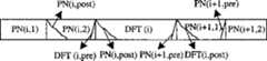
TDS-OFDM使用PN序列作为保护间隔,PN同步头与DFT块是时分复用的,这样由于多径干扰,将使DFT部分受前后含有PN序列的同步头干扰。在对数据DFT块进行DFT之前我们要将PN序列从DFT块中去除,并构造DFT块与信道的循环卷积。如图2所示,PN(i)与信道后径的线性卷积结果PN(i,post)搬移叠加到DFT(i)的首部DFT(i,head),得到对应DFT(i)首部的叠加信号DFTc(i,head),而PN(i+1)与信道前径的线性卷积结果PN(i,pre)搬移叠加到DFT(i)的尾部DFT(i,tail)得到DFTc(i,tail),公式表示为:TDS-OFDM uses the PN sequence as the guard interval, and the PN synchronous header and the DFT block are time-division multiplexed, so due to multipath interference, the DFT part will be interfered by the synchronous header containing the PN sequence before and after. Before performing DFT on the data DFT block, we need to remove the PN sequence from the DFT block, and construct the circular convolution of the DFT block and the channel. As shown in Figure 2, the linear convolution result PN(i, post) of PN(i) and the channel back path is moved and superimposed to the head DFT(i, head) of DFT(i), and the superposition corresponding to the head of DFT(i) is obtained The signal DFTc(i, head), and the linear convolution result PN(i, pre) of PN(i+1) and the channel front diameter is moved and superimposed to the tail DFT(i, tail) of DFT(i) to obtain DFTc(i, tail), the formula is expressed as:
DFTc(i,head)=DFT(i,head)+PN(i,post) (7)DFTc (i, head) = DFT (i, head) + PN (i, post) (7)
DFTc(i,tail)=DFT(i,tail)+PN(i+1,pre)DFTc (i, tail) = DFT (i, tail) + PN (i+1, pre)
下标c表示叠加的信号。对应于PN(i)有:The subscript c indicates the superimposed signal. Corresponding to PN(i) are:
PNc(i,tail)=PN(i,tail)+DFT(i,pre)PNc (i, tail) = PN (i, tail) + DFT (i, pre)
PNc(i+1,head)=PN(i+1,head)+DFT(i,post)PNc (i+1, head) = PN (i+1, head) + DFT (i, post)
先构造DFT(i)与信道前径的循环卷积,此时要得到:First construct the circular convolution of DFT(i) and the channel front path, at this time to get:
DFT(i,tail)+DFT(i,pre)={DFTc(i,tail)-PN(i+1,pre)} (9)DFT(i, tail)+DFT(i, pre)={DFTc (i, tail)-PN(i+1, pre)} (9)
+{PNc(i,tail)-PN(i,tail)}+{PNc (i, tail)-PN(i, tail)}
上式中除PN(i+1,pre)信号外,其它均已知。又PN信号PN(i+1)总长Ng为512,而PN序列长度K取255,这样可以分出两个长度均为255的相等的PN序列PN(i+1,1)和PN(i+1,2),如图2所示。这样有Except for the PN(i+1, pre) signal in the above formula, all others are known. The PN signal PN(i+1) has a total length Ng of 512, and the PN sequence length K is 255, so that two equal PN sequences PN(i+1, 1) and PN(i +1, 2), as shown in Figure 2. so there is
PN(i+1,pre)=PNc(i+1,tail)-PN(i+1,tail) (10)PN(i+1, pre)=PNc (i+1, tail)-PN(i+1, tail) (10)
其中PNc(i+1,1,tail)和PN(i+1,1,tail)分别对应PN(i+1,1)的尾部叠加信号和尾部信号。Among them, PNc (i+1, 1, tail) and PN (i+1, 1, tail) correspond to the tail superposition signal and tail signal of PN (i+1, 1), respectively.
这样经过信号加减操作,即可得到DFT(i)与信道前径的循环卷积。同样的方法可以得到DFT(i)与信道后径的循环卷积。In this way, through signal addition and subtraction operations, the circular convolution of DFT(i) and channel front path can be obtained. The same method can obtain the circular convolution of DFT(i) and channel backpath.
构造DFT(i)与信道前径的循环卷积,此时要得到:Construct the circular convolution of DFT(i) and the channel front path, at this time to get:
DFT(i,head)+DFT(i,post)={DFTc(i,head)-PN(i+1,post)} (11)DFT(i, head)+DFT(i, post)={DFTc (i, head)-PN(i+1, post)} (11)
+{PNc(i,head)-PN(i,head)}+{PNc (i, head)-PN(i, head)}
上式中除PN(i+1,post)信号外,其它均已知。又PN信号PN(i+1)总长Ng为512,而PN序列长度K取255,这样可以分出两个长度均为255的相等的PN序列PN(i+1,1)和PN(i+1,2),如图2所示。这样有Except for the PN(i+1, post) signal in the above formula, all others are known. The PN signal PN(i+1) has a total length Ng of 512, and the PN sequence length K is 255, so that two equal PN sequences PN(i+1, 1) and PN(i +1, 2), as shown in Figure 2. so there is
PN(i+1,post)=PNc(i+1,head)-PN(i+1,head) (12)PN(i+1, post) = PNc (i+1, head) - PN(i+1, head) (12)
其中PNc(i+1,head)和PN(i+1,head)分别对应PN(i+1,1)的首部叠加信号和首部信号。从而完成了DFT(i)与信道的循环卷积构造,接着就可以对DFT(i)进行DFT操作了,得到频域输出Y(n,k)。Wherein PNc (i+1, head) and PN (i+1, head) respectively correspond to the superimposed head signal and the head signal of PN (i+1, 1). Thus, the circular convolution construction of DFT(i) and the channel is completed, and then the DFT operation can be performed on DFT(i) to obtain the frequency domain output Y(n,k).
由于PN头的长度相对于整个OFDM块的长度小很多,可以假定信道在PN头处保持不变。不考虑数据对同步头的干扰,接收到的PN码帧同步(帧头)r(n,N0,m)(N0代表PN头在每个OFDM块内的相对位置编号)可表示为:Since the length of the PN header is much smaller than that of the entire OFDM block, it can be assumed that the channel remains unchanged at the PN header. Regardless of the interference of the data on the synchronization header, the received PN code frame synchronization (frame header) r(n, N0 , m) (N0 represents the relative position number of the PN header in each OFDM block) can be expressed as:
式中的h(n,N0,l)为信道在第n个OFDM块内的PN头处的时域冲激响应,z(n,m)为高斯白噪声,c(m)为使用的PN序列,它具有良好的相关特性,其归一化相关函数ρ(m)可表示为:In the formula, h(n, N0 , l) is the time-domain impulse response of the channel at the PN head in the nth OFDM block, z(n, m) is Gaussian white noise, and c(m) is the used PN sequence, which has good correlation characteristics, its normalized correlation function ρ(m) can be expressed as:
其中m1、m表示序号,Q为PN序列的长度。Among them, m1 and m represent serial numbers, and Q is the length of the PN sequence.
经过PN码时域相关即可得到信道在PN头处的时域冲激响应的粗估计:A rough estimate of the time-domain impulse response of the channel at the PN head can be obtained through time-domain correlation of the PN code:
得到的粗估计中的小电平值被丢弃,因为存在白噪声和多径时,这些小电平已经不可靠了,门限的选择可视应用所要求的不同的抗噪声和分辨多径的灵敏性来决定。假设信道的主径为第一条径,那么经过N点DFT处理便可得到在PN头处的信道频率响应的估计get a rough estimate The small level values in are discarded, because these small levels are no longer reliable in the presence of white noise and multipath. The selection of the threshold can be determined by the different anti-noise and sensitivity to resolve multipath required by the application. Assuming that the main path of the channel is the first path, then the estimation of the channel frequency response at the PN head can be obtained after N-point DFT processing
假设信道在一个OFDM块内呈线性变化,根据在PN头处的信道频率响应估计进行OFDM块内信道频率响应估计的线性内插,从而得到每个OFDM块内每个数据时刻的信道频率响应估计
将做一个OFDM块的延时,得到第n个OFDM块与第n-1个OFDM块的PN头时刻的频率响应估计的平均值

不难得到在一个OFDM块内对频率响应估计做线性插值:It is not hard to get linear interpolation of the frequency response estimate within an OFDM block:
其中,
N为DFT的长度,Nf为整个OFDM块的长度,即PN头的长度与DFT的长度之和。N is the length of the DFT, and Nf is the length of the entire OFDM block, that is, the sum of the length of the PN header and the length of the DFT.
根据频域输出Y(n,k)和两个连续OFDM块在PN头处的信道频率响应估计的平均值与差值通过理论推导,可以得出对具有子载波干扰(ICI)的均衡矩阵求逆进行有限项幂级数展开的简化均衡方法,如图5,图6所示。Output Y(n,k) from the frequency domain and the average of the channel frequency response estimates at the PN header for two consecutive OFDM blocks and difference Through theoretical derivation, a simplified equalization method for inverting the equalization matrix with subcarrier interference (ICI) and performing finite power series expansion can be obtained, as shown in Fig. 5 and Fig. 6 .
设发送的数据矢量为Z(n),假设信道在一个OFDM块内呈线性变化,则系统传输模型可以由下式表示:Assuming that the transmitted data vector is Z(n), assuming that the channel changes linearly within an OFDM block, the system transmission model can be expressed by the following formula:
Y(n)=(I-T(n))D(HA(n))Z(n)+σ(n) (22)Y(n)=(IT(n))D(HA (n))Z(n)+σ(n) (22)
其中,σ(n)为高斯白噪声矢量,Among them, σ(n) is the Gaussian white noise vector,
Z(n)=[Z(n,1),Z(n,2)...,Z(n,N)]T (23)Z(n) = [Z(n, 1), Z(n, 2)..., Z(n, N)]T (23)
Y(n)=[Y(n,1),Y(n,2)...,Y(n,N)]T (24)Y(n) = [Y(n, 1), Y(n, 2)..., Y(n, N)]T (24)
在上式中,W和WH分别为DFT矩阵和IDFT矩阵,In the above formula, W and WH are DFT matrix and IDFT matrix respectively,

从而可以得到对发送数据矢量的估计:An estimate of the transmitted data vector can thus be obtained:
但是,由于上式在实现时的复杂度太高,为O(N3)+N2+2·O(NlogN)+N次复数乘法运算。其中O(N3)为矩阵求逆的复杂度,O(NlogN)为DFT的复杂度。为了复杂度的简化,根据对形如(I-T)-1的矩阵求逆进行幂级数展开,只保留低阶项:However, since the complexity of the above formula is too high when it is implemented, it is O(N3 )+N2 +2·O(NlogN)+N complex multiplication operations. Among them, O(N3 ) is the complexity of matrix inversion, and O(NlogN) is the complexity of DFT. In order to simplify the complexity, according to the power series expansion of the matrix inversion of the shape (IT)-1 , only the low-order items are kept:
这一简化是本发明提出的对具有子载波干扰(ICI)的均衡矩阵求逆进行有限项幂级数展开的简化均衡方法的核心思想。根据上式可以得到:This simplification is the core idea of the simplified equalization method proposed by the present invention for inverting the equalization matrix with subcarrier interference (ICI) and performing finite term power series expansion. According to the above formula can be obtained:
上式即为具有子载波间干扰(ICI)的均衡矩阵求逆进行有限项幂级数展开的简化均衡方法,如图5,图6所示。由于
由于A和都为对角阵,并且W和WH分别为DFT矩阵和IDFT矩阵,所以上式可以通过DFT变换和IDFT变换来实现,实现的复杂度为2·(O(NlogN)+N)次复数乘法运算,其中O(NlogN)为一个DFT的运算复杂度。因此,
由于PSS均衡算法是对PDS均衡算法的近似,因此近似误差必然会带来系统性能的损失,在这一部分将从理论上分析PSS均衡算法和PDS均衡算法的相对误差。Since the PSS equalization algorithm is an approximation to the PDS equalization algorithm, the approximation error will inevitably lead to the loss of system performance. In this part, the relative error between the PSS equalization algorithm and the PDS equalization algorithm will be analyzed theoretically.
为了简化推导,在以下分析中我们省去标号n。那么式(30)的近似处理可以写成:In order to simplify the derivation, we omit the label n in the following analysis. Then the approximate processing of formula (30) can be written as:
为了分析上式所作的近似带来的误差,定义如下的M阶相对误差:In order to analyze the error caused by the approximation made by the above formula, the following M-order relative error is defined:
其中,‖·‖2代表l2上的标准范数。上式给出了对均衡矩阵求逆进行M阶幂级数近似的相对误差表达式。其中和1取最小值保证了相对误差不大于1。对上式作进一步的简化,不难得到:Among them, ‖·‖2 represents the standard norm on l2 . The above formula gives the relative error expression for the M-order power series approximation of the equilibrium matrix inversion. Wherein and 1 take the minimum value to ensure that the relative error is not greater than 1. By further simplifying the above formula, it is not difficult to get:
其中,‖T‖为矩阵T的谱范数,它的定义为:Among them, ‖T‖ is the spectral norm of matrix T, which is defined as:
而根据式(26)可以得到:And according to formula (26), we can get:
由于DFT矩阵W和IDFT矩阵WH为酉矩阵,所以:Since DFT matrix W and IDFT matrix WH are unitary matrices, so:
‖w‖=‖WH‖ =1 (39)‖w‖=‖WH ‖=1 (39)
另外,in addition,
定义:definition:
则式(38)可以变为:Then formula (38) can be changed into:
‖T‖≤b* (43)‖T‖≤b* (43)
再根据式(35),式(36)可以得到:Then according to formula (35), formula (36) can get:
ηT(M)=min{‖TM+1‖,1}≤min{b*M+1,1) (44)ηT (M)=min{‖TM+1 ‖, 1}≤min{b*M+1 , 1) (44)
为了求出b*的概率分布的显示表达式,作如下近似:In order to find the explicit expression of the probability distribution of b* , the following approximation is made:
当|rf[k]|<δ时,

当|rf[k]≥δ时,与完全相同;When |rf [k]≥δ, and exactly the same;
这里,称δ为独立一相同阙值,rf[k]为信道的频率相关系数,定义如下:Here, δ is called independent-identity threshold, and rf [k] is the frequency correlation coefficient of the channel, which is defined as follows:
其中,σl2为第l条径的功率,σH2为所有径的功率之和。那么,可以得到b*的累积分布函数的近似表达式为:Among them, σl2 is the power of the lth path, and σH2 is the sum of the power of all paths. Then, the approximate expression of the cumulative distribution function of b* can be obtained as:
其中,in,
在上式中,count{k:|rf[k]|≥δ}代表|rf[k]|≥δ的k的个数;代表不大于x的最大整数。In the above formula, count{k:|rf [k]|≥δ} represents the number of k with |rf [k]|≥δ; Represents the largest integer not greater than x.
在上式中,rt[m]为信道的时间相关系数,定义如下:In the above formula, rt [m] is the time correlation coefficient of the channel, defined as follows:
rt[m]=J0(m·2πTsfd) (49)rt [m]=J0 (m·2πTs fd ) (49)
其中,J0(x)为0阶第一类贝塞尔函数,Ts为采样频率,fd为多普勒频移。对式(46)求导,可以得到b*的概率密度函数的近似表达式如下:Among them, J0 (x) is the 0th order Bessel function of the first kind, Ts is the sampling frequency, and fd is the Doppler frequency shift. Taking the derivative of formula (46), the approximate expression of the probability density function of b* can be obtained as follows:
由上式可以得到ηT(M)的均值的上界如下:Can obtain the upper bound of the mean value of ηT (M) by above formula as follows:
同理可得ηT(M)的方差的上界如下:Similarly, the upper bound of the variance of ηT (M) can be obtained as follows:
图10和图11分别给出了提出的PSS均衡算法与PDS均衡算法的相对误差的均值和方差的理论上界随多普勒频移变化的曲线。这里信道采用表1给出的COST207信道参数。选择δ=0.5,则根据式(47)可以得到Iδ=3。从图中可以看出,当M取值变大时,相对误差的均值和方差的理论上界会下降,系统性能相应会提高,但是M越大,实现的复杂度越高。当M的取值从0变到1时,相对误差的均值和方差的理论上界有明显的下降,而当M的取值大于2时,相对误差的均值和方差的理论上界基本保持不变。因此,当性能和复杂度同时考虑时,M=1或M=2为最好的选择。Fig. 10 and Fig. 11 respectively show the curves of the theoretical upper bounds of the relative error mean and variance of the proposed PSS equalization algorithm and PDS equalization algorithm changing with Doppler frequency shift. Here the channel adopts the COST207 channel parameters given in Table 1. If δ=0.5 is selected, Iδ =3 can be obtained according to formula (47). It can be seen from the figure that when the value of M becomes larger, the theoretical upper bounds of the mean value and variance of the relative error will decrease, and the system performance will increase accordingly, but the larger M is, the higher the complexity of implementation will be. When the value of M changes from 0 to 1, the theoretical upper bounds of the mean and variance of the relative error decrease significantly, while when the value of M is greater than 2, the theoretical upper bounds of the mean and variance of the relative error basically remain constant. Change. Therefore, when both performance and complexity are considered, M=1 or M=2 is the best choice.
综合上述,本发明在TDS-OFDM的系统框架上,突破了原有的假定OFDM块内信道不变的假设,假定信道在一个OFDM块内为线性变化,提出了TDS-OFDM接收机的时变信道估计与均衡方法及其系统,即基于PN码时域相关的OFDM块内线性内插信道估计方法和对具有子载波干扰(ICI)的均衡矩阵求逆进行有限项幂级数展开的简化均衡方法,整体框图如图12,图13所示。本发明一方面大大提高了TDS-OFDM接收机在时变信道环境下的接收性能,明显优于不考虑信道在一个OFDM块内变化的方案。另一方面也做了均衡器复杂度的简化,保证了接收机具有较低的复杂度。In summary, on the system frame of TDS-OFDM, the present invention breaks through the original assumption that the channel in the OFDM block is constant, assumes that the channel changes linearly in an OFDM block, and proposes a time-varying TDS-OFDM receiver. Channel estimation and equalization method and its system, that is, OFDM intra-block linear interpolation channel estimation method based on PN code time-domain correlation and simplified equalization with finite-term power series expansion for equalization matrix inversion with subcarrier interference (ICI) method, the overall block diagram is shown in Figure 12 and Figure 13. On the one hand, the invention greatly improves the receiving performance of a TDS-OFDM receiver in a time-varying channel environment, and is obviously superior to a scheme that does not consider channel changes within an OFDM block. On the other hand, the complexity of the equalizer is also simplified to ensure a lower complexity of the receiver.
在计算机仿真的基础上,本发明可以在清华DMB-T系统的现场可编程门阵列(FPGA)或专用集成电路(ASIC)版本接收机中得到实现。On the basis of computer simulation, the present invention can be realized in the field programmable gate array (FPGA) or application specific integrated circuit (ASIC) version receiver of Tsinghua DMB-T system.
上面结合附图对本发明的具体实施例进行了详细说明,但本发明并不限制于上述实施例,在不脱离本申请的权利要求的精神和范围情况下,本领域的技术人员可作出各种修改或改型。Specific embodiments of the present invention have been described in detail above in conjunction with the accompanying drawings, but the present invention is not limited to the above embodiments, and those skilled in the art can make various modifications without departing from the spirit and scope of the claims of the application modify or remodel.
Claims (2)
Translated fromChinese


Priority Applications (1)
| Application Number | Priority Date | Filing Date | Title |
|---|---|---|---|
| CNB2004100099441ACN100376103C (en) | 2004-12-03 | 2004-12-03 | Time-varying channel estimation and equalization method and system for TDS-OFDM receiver |
Applications Claiming Priority (1)
| Application Number | Priority Date | Filing Date | Title |
|---|---|---|---|
| CNB2004100099441ACN100376103C (en) | 2004-12-03 | 2004-12-03 | Time-varying channel estimation and equalization method and system for TDS-OFDM receiver |
Publications (2)
| Publication Number | Publication Date |
|---|---|
| CN1617531Atrue CN1617531A (en) | 2005-05-18 |
| CN100376103C CN100376103C (en) | 2008-03-19 |
Family
ID=34763138
Family Applications (1)
| Application Number | Title | Priority Date | Filing Date |
|---|---|---|---|
| CNB2004100099441AExpired - Fee RelatedCN100376103C (en) | 2004-12-03 | 2004-12-03 | Time-varying channel estimation and equalization method and system for TDS-OFDM receiver |
Country Status (1)
| Country | Link |
|---|---|
| CN (1) | CN100376103C (en) |
Cited By (11)
| Publication number | Priority date | Publication date | Assignee | Title |
|---|---|---|---|---|
| US7720183B2 (en) | 2006-12-28 | 2010-05-18 | Industrial Technology Research Institute | Apparatus and method for inter-carrier interference self-cancellation and inter-carrier interference reconstruction and cancellation |
| CN101227440B (en)* | 2008-02-14 | 2010-07-21 | 北京创毅视讯科技有限公司 | Apparatus and method for eliminating zero-frequency interference in channel estimation |
| CN101299734B (en)* | 2007-03-19 | 2011-06-29 | 清华大学 | A Method of Channel Equalization |
| CN101453443B (en)* | 2008-12-18 | 2012-02-22 | 上海交通大学 | Apparatus for Quickly Obtaining Optimal Polynomial Interpolation Coefficients |
| CN101312378B (en)* | 2008-05-20 | 2012-04-18 | 北京创毅视讯科技有限公司 | Method for estimating delay spread parameter of receiver and delay spread parameter estimation unit |
| US8209570B2 (en) | 2006-09-12 | 2012-06-26 | Oki Techno Centre (Singapore) Pte Ltd | Apparatus and method for receiving digital video signals |
| CN101422004B (en)* | 2005-12-29 | 2013-01-02 | 创达特(苏州)科技有限责任公司 | Time-domain equalizer |
| CN101656698B (en)* | 2009-09-09 | 2013-05-08 | 上海高清数字科技产业有限公司 | Channel estimation method and device |
| CN103546406A (en)* | 2012-07-11 | 2014-01-29 | 三菱电机株式会社 | Equalization device, equalization method, received signal processing device and method |
| CN104394105A (en)* | 2014-11-25 | 2015-03-04 | 清华大学 | TDS-OFDM (Time Domain Synchronous-Orthogonal Frequency Division Multiplexing) channel estimation equalization method and system |
| CN109714142A (en)* | 2019-03-11 | 2019-05-03 | 西安电子科技大学 | Efficient OTDM transmitting method and system |
Family Cites Families (4)
| Publication number | Priority date | Publication date | Assignee | Title |
|---|---|---|---|---|
| JPH02231837A (en)* | 1989-03-03 | 1990-09-13 | Nec Corp | Priority call control system |
| KR100852278B1 (en)* | 2002-05-27 | 2008-08-14 | 삼성전자주식회사 | OFDM Transmitter capable of preventing the distortion of OFDM signal according to inserting synchronization symbol |
| KR100859878B1 (en)* | 2002-05-30 | 2008-09-24 | 삼성전자주식회사 | UFDM transmitter which can insert pseudo noise string information per UFDM symbol according to service mode and OHDM transmission method using same |
| KR20040029824A (en)* | 2002-10-02 | 2004-04-08 | 삼성전자주식회사 | TDS-OFDM transmission system having 3600-point IDFT procseeor and a method proessing OFDM signal thereof |
- 2004
- 2004-12-03CNCNB2004100099441Apatent/CN100376103C/ennot_activeExpired - Fee Related
Cited By (12)
| Publication number | Priority date | Publication date | Assignee | Title |
|---|---|---|---|---|
| CN101422004B (en)* | 2005-12-29 | 2013-01-02 | 创达特(苏州)科技有限责任公司 | Time-domain equalizer |
| US8209570B2 (en) | 2006-09-12 | 2012-06-26 | Oki Techno Centre (Singapore) Pte Ltd | Apparatus and method for receiving digital video signals |
| US7720183B2 (en) | 2006-12-28 | 2010-05-18 | Industrial Technology Research Institute | Apparatus and method for inter-carrier interference self-cancellation and inter-carrier interference reconstruction and cancellation |
| CN101299734B (en)* | 2007-03-19 | 2011-06-29 | 清华大学 | A Method of Channel Equalization |
| CN101227440B (en)* | 2008-02-14 | 2010-07-21 | 北京创毅视讯科技有限公司 | Apparatus and method for eliminating zero-frequency interference in channel estimation |
| CN101312378B (en)* | 2008-05-20 | 2012-04-18 | 北京创毅视讯科技有限公司 | Method for estimating delay spread parameter of receiver and delay spread parameter estimation unit |
| CN101453443B (en)* | 2008-12-18 | 2012-02-22 | 上海交通大学 | Apparatus for Quickly Obtaining Optimal Polynomial Interpolation Coefficients |
| CN101656698B (en)* | 2009-09-09 | 2013-05-08 | 上海高清数字科技产业有限公司 | Channel estimation method and device |
| CN103546406A (en)* | 2012-07-11 | 2014-01-29 | 三菱电机株式会社 | Equalization device, equalization method, received signal processing device and method |
| CN103546406B (en)* | 2012-07-11 | 2016-12-28 | 三菱电机株式会社 | Balancer, equalization methods, reception signal processing apparatus and method |
| CN104394105A (en)* | 2014-11-25 | 2015-03-04 | 清华大学 | TDS-OFDM (Time Domain Synchronous-Orthogonal Frequency Division Multiplexing) channel estimation equalization method and system |
| CN109714142A (en)* | 2019-03-11 | 2019-05-03 | 西安电子科技大学 | Efficient OTDM transmitting method and system |
Also Published As
| Publication number | Publication date |
|---|---|
| CN100376103C (en) | 2008-03-19 |
Similar Documents
| Publication | Publication Date | Title |
|---|---|---|
| CN1207908C (en) | Method based on slide window for estimating and equalizing channels of block signals containing pilot | |
| CN1290281C (en) | Apparatus and method for coding/decoding of STTD in OFDM mobile communication system | |
| CN1287531C (en) | Adaptive blanced device and its program | |
| CN1172472C (en) | Receiving processing method and receiving device in mobile communication system | |
| CN101039295A (en) | Method for improving synchronization performance of OFDM system using low correlated code | |
| CN1930790A (en) | Data transmission with spatial spreading in a mimo communication system | |
| CN1703863A (en) | Space-time coded transmissions within a wireless communication network | |
| CN101068124A (en) | Method and system for processing signals in a communication system | |
| CN1618222A (en) | Iterative detection and decoding for a MIMO-OFDM system | |
| CN1677908A (en) | TDS-OFDM Receiver Adaptive Channel Estimation Equalization Method and System | |
| CN1617534A (en) | OFDM receiver | |
| CN1643867A (en) | Device and method for estimating channels | |
| CN1496107A (en) | Channel balancer and digital TV receiver using the same | |
| CN1675940A (en) | Rate Control for Multi-Channel Communication Systems | |
| CN1682507A (en) | Frequency domain equalization in communications systems with scrambling | |
| CN1653768A (en) | Precoding of Multipath Channels in MIMO Systems | |
| CN1860712A (en) | Iterative decoding and equalingzing method for hgih speed communications on multiple antenna channels during transmission and reception | |
| CN1561591A (en) | Multi-carrier CDMA transmission system, transmitting apparatus and receiving apparatus used in the system, multi-carrier CDMA transmission method | |
| CN1617531A (en) | TDS-OFDM receiver time-varying channel estimation and equalization method and system | |
| CN1574715A (en) | Orthogonal frequency division multiple task receiver and receiving method | |
| CN1889555A (en) | Iterative decoding algorithm for space hour bit interlaced modulating system and receiving system | |
| CN1802796A (en) | Communication method and apparatus for multi-user detection | |
| CN1200521C (en) | Method for inserting pilot frequency and estimating parameters of channel for equilibrium in frequency doman | |
| CN1513247A (en) | Method for estimating transfer function of multi-carrier signal transmission channel and corresponding receiver | |
| CN1708037A (en) | Method for receiving data signal, corresponding receiving device and computer program product |
Legal Events
| Date | Code | Title | Description |
|---|---|---|---|
| C06 | Publication | ||
| PB01 | Publication | ||
| C10 | Entry into substantive examination | ||
| SE01 | Entry into force of request for substantive examination | ||
| C14 | Grant of patent or utility model | ||
| GR01 | Patent grant | ||
| CF01 | Termination of patent right due to non-payment of annual fee | Granted publication date:20080319 Termination date:20161203 | |
| CF01 | Termination of patent right due to non-payment of annual fee |