CN1616854A - Power transmission device and hydraulic torque converter lock-up control method - Google Patents
Power transmission device and hydraulic torque converter lock-up control methodDownload PDFInfo
- Publication number
- CN1616854A CN1616854ACN200410092914.1ACN200410092914ACN1616854ACN 1616854 ACN1616854 ACN 1616854ACN 200410092914 ACN200410092914 ACN 200410092914ACN 1616854 ACN1616854 ACN 1616854A
- Authority
- CN
- China
- Prior art keywords
- lock
- clutch
- torque converter
- state
- loop control
- Prior art date
- Legal status (The legal status is an assumption and is not a legal conclusion. Google has not performed a legal analysis and makes no representation as to the accuracy of the status listed.)
- Granted
Links
- 238000000034methodMethods0.000titleclaimsdescription35
- 230000005540biological transmissionEffects0.000titleclaimsdescription26
- 230000007246mechanismEffects0.000claimsabstractdescription12
- 230000008859changeEffects0.000claimsdescription90
- 239000012530fluidSubstances0.000claimsdescription17
- 230000007704transitionEffects0.000abstractdescription18
- 230000008569processEffects0.000description25
- 238000012545processingMethods0.000description15
- 230000009194climbingEffects0.000description6
- 238000010586diagramMethods0.000description6
- 230000001133accelerationEffects0.000description4
- 102100027988GTP-binding protein RhesHuman genes0.000description3
- 101000578396Homo sapiens GTP-binding protein RhesProteins0.000description3
- 238000006243chemical reactionMethods0.000description3
- 230000007423decreaseEffects0.000description3
- 230000001419dependent effectEffects0.000description2
- 230000004044responseEffects0.000description2
- 239000003638chemical reducing agentSubstances0.000description1
- 238000007796conventional methodMethods0.000description1
- 238000013016dampingMethods0.000description1
- 239000000446fuelSubstances0.000description1
- 230000006870functionEffects0.000description1
- 238000012986modificationMethods0.000description1
- 230000004048modificationEffects0.000description1
- 230000010355oscillationEffects0.000description1
- 238000010187selection methodMethods0.000description1
- 238000013169thromboelastometryMethods0.000description1
- 238000012546transferMethods0.000description1
- 230000009466transformationEffects0.000description1
- 238000004627transmission electron microscopyMethods0.000description1
Images


Classifications
- F—MECHANICAL ENGINEERING; LIGHTING; HEATING; WEAPONS; BLASTING
- F16—ENGINEERING ELEMENTS AND UNITS; GENERAL MEASURES FOR PRODUCING AND MAINTAINING EFFECTIVE FUNCTIONING OF MACHINES OR INSTALLATIONS; THERMAL INSULATION IN GENERAL
- F16H—GEARING
- F16H61/00—Control functions within control units of change-speed- or reversing-gearings for conveying rotary motion ; Control of exclusively fluid gearing, friction gearing, gearings with endless flexible members or other particular types of gearing
- F16H61/14—Control of torque converter lock-up clutches
- F16H61/143—Control of torque converter lock-up clutches using electric control means
Landscapes
- Engineering & Computer Science (AREA)
- General Engineering & Computer Science (AREA)
- Mechanical Engineering (AREA)
- Control Of Fluid Gearings (AREA)
Abstract
Translated fromChineseDescription
Translated fromChinese技术领域technical field
本发明涉及具有带锁止离合器的液力变矩器的动力传动装置。The present invention relates to a power transmission having a torque converter with a lock-up clutch.
背景技术Background technique
存在能够在三种工作状态,即变换状态(converter state)、锁止状态和滑动(slip)状态之间转换的液力变矩器。There are torque converters capable of switching between three operating states, namely a converter state, a locked state and a slip state.
变换状态是其中输入部件和输出部件被完全释放,并通过流体传递转矩的状态。锁止状态是在不需要转矩增大操作和传动减震功能的工作区中选择的状态,以便减小由液力变矩器的滑动导致的燃料效率的降低。这种状态下,液力变矩器的输入部件直接与输出部件连接。滑动状态保持其中在锁止离合器处于半连接状态下,在输入部件和输出部件之间形成滑动的状态。The commutation state is the state in which the input member and output member are fully released and torque is transmitted through the fluid. The lock-up state is a state selected in an operating region where the torque increasing operation and the transmission damping function are not required in order to reduce a decrease in fuel efficiency caused by slipping of the torque converter. In this state, the input part of the torque converter is directly connected to the output part. The slip state maintains a state in which slip is formed between the input member and the output member while the lock-up clutch is in the half-connected state.
在JP2665597B中,当锁止差压增大,以致液力变矩器从变换状态到达滑动状态时,根据开始控制时的滑动转速ΔN(ΔN=涡轮转速Nt-发动机转速Ne),设置锁止差压的最大值。In JP2665597B, when the lock-up differential pressure increases so that the torque converter reaches the slip state from the conversion state, the lock-up differential is set according to the slip speed ΔN at the start of control (ΔN=turbine speed Nt-engine speed Ne) maximum pressure.
在确定滑动转速的参数(涡轮转速Nt和发动机转速Ne)中,涡轮转速(变速器输入转速)取决于行驶阻力和爬坡阻力。当比较沿着平直道路行驶和沿着爬升道路行驶时,和平直道路相比,在爬升道路上,涡轮转速增长更加缓慢。Among the parameters determining the slip rotation speed (turbine rotation speed Nt and engine rotation speed Ne), the turbine rotation speed (transmission input rotation speed) depends on running resistance and climbing resistance. When comparing driving along a straight road with driving along a climb, the turbo speed increases more slowly on the climb compared to the straight road.
对于连续可变变速器来说,涡轮转速是根据车速确定的值。因此,涡轮转速的增长率由速度变化开始之前的时段内,车速的增长率确定。参见图22,当在节气门开度(throttle opening)TVO=3/8的情况下,从车速VSP=0实现加速时,从达到对应于图中A点的车速的时刻朝着Hi(高)一侧开始速度变化。在直到该时刻为止的时段中,齿轮变换比保持在最小值。For a continuously variable transmission, the turbine speed is a value determined according to the vehicle speed. Therefore, the increase rate of the turbine rotation speed is determined by the increase rate of the vehicle speed in the period before the start of the speed change. Referring to Fig. 22, when acceleration is achieved from vehicle speed VSP = 0 under the condition of throttle opening (throttle opening) TVO = 3/8, from the moment of reaching the vehicle speed corresponding to point A in the figure toward Hi (high) The speed changes on one side. During the period up to this moment, the gear conversion ratio is kept at the minimum value.
但是,上述常规技术没有考虑到在速度变化开始之前的时段内,涡轮转速取决于行驶阻力,爬坡阻力等的事实。从而仅仅根据控制开始时的信息,设置锁止差压的增大量,并在开环控制下,实现从变换状态到滑动状态的液力变矩器转变。However, the above conventional technique does not take into account the fact that the turbine rotational speed depends on running resistance, hill climbing resistance, etc. in the period before the speed change starts. Therefore, only according to the information at the beginning of the control, the increase amount of the lock-up differential pressure is set, and under the open-loop control, the transition of the hydraulic torque converter from the switching state to the slipping state is realized.
例如,当沿着平直道路行驶时和当沿着爬升道路行驶时,设置相同的增长量。因此,参见图16A,当在平直道路上行驶时,在车速已充分增大之后,发生从变换状态到滑动状态的液力变矩器转变。但是,参见图16B,在车速增大之前,发生到滑动状态的液力变矩器转变。在低的涡轮转速下,在开环控制结束之前,结束到滑动状态的液力变矩器转变。因此,会形成压抑的声音和振动,此外,在低于标准值的涡轮转速下发生到滑动状态的液力变矩器转变。从而,当转变到滑动状态时的发动机转速的步进变化变得更大。For example, the same increase amount is set when traveling along a straight road and when traveling along a climbing road. Therefore, referring to FIG. 16A , when traveling on a straight road, the torque converter transition from the shift state to the slip state occurs after the vehicle speed has increased sufficiently. However, referring to FIG. 16B , the torque converter transition to the slip state occurs before the vehicle speed increases. At low turbine speeds, the torque converter transition to the slip state ends before open loop control ends. As a result, muffled sounds and vibrations are created and, moreover, a torque converter transition to a slipping state occurs at turbine speeds below the standard value. Thus, the step change in the engine speed when transitioning to the slip state becomes larger.
发明内容Contents of the invention
于是,本发明的一个目的是通过消除锁止离合器中的突然锁止和锁止延迟,当借助开环控制从变换状态变到滑动状态时,实现平稳控制。It is therefore an object of the present invention to achieve smooth control when changing from a shifting state to a slipping state by means of open loop control by eliminating sudden lockup and lockup delay in a lockup clutch.
为了实现上述目的,本发明提供一种把发动机的动力传送给驱动轮的动力传动装置,所述动力传动装置包括:自动变速器;包括锁止离合器的液力变矩器,液力变矩器置于发动机和自动变速器之间;转换锁止离合器的接合状态的转换机构;和当液力变矩器从使锁止离合器脱离的第一状态转变到锁止离合器至少被部分接合的第二状态时,通过转换机构执行锁止离合器的接合状态的开环控制的控制器。In order to achieve the above object, the present invention provides a power transmission device that transmits the power of the engine to the driving wheels, and the power transmission device includes: an automatic transmission; a torque converter including a lock-up clutch; Between the engine and the automatic transmission; a switching mechanism that switches the engaged state of the lock-up clutch; and when the torque converter transitions from a first state in which the lock-up clutch is disengaged to a second state in which the lock-up clutch is at least partially engaged , a controller that performs open-loop control of the engagement state of the lock-up clutch through the switching mechanism.
控制器估计开环控制结束时发动机的转矩;根据估计的发动机的转矩,估计开环控制结束时液力变矩器所需的必需锁止容量;并通过转换机构,控制锁止离合器的接合状态,使开环控制结束时的锁止容量成为必需锁止容量。The controller estimates the torque of the engine at the end of the open-loop control; based on the estimated torque of the engine, estimates the required lock-up capacity required by the torque converter at the end of the open-loop control; and controls the torque of the lock-up clutch through the switching mechanism. In the engaged state, the lockup capacity at the end of the open loop control becomes the necessary lockup capacity.
根据本发明的一个方面,本发明提供一种液力变矩器的锁止控制方法,其中当液力变矩器从锁止离合器脱离的第一状态转变到锁止离合器至少被部分接合的第二状态时,对锁止离合器的接合状态进行开环控制。锁止控制方法包括估计开环控制结束时的发动机转矩;根据估计的发动机转矩,估计开环控制结束时液力变矩器所需的必需锁止容量;并控制锁止离合器的接合状态,使开环控制结束时的锁止容量成为必需锁止容量。According to one aspect of the present invention, the present invention provides a lock-up control method of a torque converter, wherein when the torque converter is transferred from a first state in which the lock-up clutch is disengaged to a second state in which the lock-up clutch is at least partially engaged In the second state, an open-loop control is performed on the engagement state of the lock-up clutch. The lockup control method includes estimating the engine torque at the end of the open loop control; estimating a necessary lockup capacity required for the torque converter at the end of the open loop control based on the estimated engine torque; and controlling the engagement state of the lockup clutch , making the lock-up capacity at the end of the open-loop control the required lock-up capacity.
本发明的细节以及其它特征和优点在说明书的剩余部分中说明,并示于附图中。The details as well as other features and advantages of the invention are set forth in the remainder of the specification and are shown in the accompanying drawings.
附图说明Description of drawings
图1是根据本发明的动力传动机构的示意结构图。FIG. 1 is a schematic structural diagram of a power transmission mechanism according to the present invention.
图2是控制器的控制方框图。Figure 2 is a control block diagram of the controller.
图3是表示控制器执行的差压命令值的计算处理的流程图。FIG. 3 is a flowchart showing calculation processing of a differential pressure command value executed by a controller.
图4是表示图2的方框B111执行的选择处理的流程图。FIG. 4 is a flowchart showing selection processing performed by block B111 of FIG. 2 .
图5是表示发动机转矩相对于节气门开度和发动机转速的关系的整个发动机性能图。FIG. 5 is an overall engine performance diagram showing the relationship of engine torque with respect to throttle opening and engine speed.
图6是表示液力变矩器的速比和容量系数之间的关系的图表。FIG. 6 is a graph showing the relationship between the speed ratio and capacity coefficient of the torque converter.
图7是表示锁止离合器的接合压力和容量之间的关系的图表。FIG. 7 is a graph showing the relationship between the engagement pressure and capacity of the lockup clutch.
图8是表示节气门开度和初始差压之间的关系的图表。FIG. 8 is a graph showing the relationship between the throttle opening and the initial differential pressure.
图9是表示当开环控制结束时,节气门开度和滑动转速之间的关系的图表。FIG. 9 is a graph showing the relationship between the throttle opening and the slip rotation speed when open-loop control is terminated.
图10表示液力变矩器控制状态相对于车速和节气门开度的关系。FIG. 10 shows the relationship of the control state of the torque converter with respect to the vehicle speed and the throttle opening.
图11是表示速度变化开始时,节气门开度和涡轮转速之间的关系的图表。FIG. 11 is a graph showing the relationship between the throttle opening and the turbine rotational speed at the start of the speed change.
图12是表示节气门开度和锁止容量的变化量的极限值之间的关系的图表。FIG. 12 is a graph showing the relationship between the throttle opening and the limit value of the change amount of the lockup capacity.
图13是表示节气门开度和锁止容量的变化量之间的关系的图表。FIG. 13 is a graph showing the relationship between the throttle opening and the amount of change in the lockup capacity.
图14是表示过转矩(overtorquing)期间,节气门开度和锁止容量命令的变化量的极限值之间的关系的图表。14 is a graph showing the relationship between the throttle opening and the limit value of the change amount of the lockup capacity command during overtorquing.
图15是表示涡轮转速和滑动转速增益之间的关系的图表。FIG. 15 is a graph showing the relationship between the turbine rotational speed and the slip rotational speed gain.
图16A和16B分别是当沿着平直道路,低速行驶时,和当沿着爬升道路,低速行驶时,常规技术中,从变换状态转变到滑动状态的液力变矩器的计时图。FIGS. 16A and 16B are timing diagrams of the torque converter transitioning from the shifting state to the slipping state in the conventional art when traveling at low speed along a straight road and when traveling at low speed along a climbing road, respectively.
图17是表示当从停止状态起动时,当液力变矩器从变换状态转变到滑动状态时的状态的计时图。Fig. 17 is a timing chart showing the state when the torque converter transitions from the shift state to the slip state when starting from a stop state.
图18是表示当在节气门开度保持不变的情况下,汽车进入爬升道路时,当液力变矩器从变换状态转变到滑动状态时的状态的计时图。18 is a timing chart showing the state when the torque converter transitions from the switching state to the slipping state when the vehicle enters a climbing road with the throttle opening kept constant.
图19是表示在液力变矩器从变换状态转变到滑动状态的时候,当节气门开度被增大时的状态的计时图。FIG. 19 is a timing chart showing the state when the throttle valve opening degree is increased when the torque converter is shifted from the shift state to the slip state.
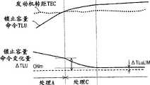
图20是表示当把锁止容量变化量的计算处理从处理A变成处理B时的状态的计时图。FIG. 20 is a timing chart showing a state when the process of calculating the amount of change in lockup capacity is changed from process A to process B. FIG.
图21是表示当把锁止容量变化量的计算处理从处理A变成处理C时的状态的计时图。FIG. 21 is a timing chart showing a state when the process of calculating the amount of change in lockup capacity is changed from process A to process C. FIG.
图22表示涡轮转速相对于车速和节气门开度的关系。FIG. 22 shows the relationship of the turbine rotational speed with respect to the vehicle speed and the throttle opening.
具体实施方式Detailed ways
参见图1,液力变矩器1置于发动机21和自动变速器22之间。来自发动机21的动力通过液力变矩器1,自动变速器22和最终减速器(未示出),被传送给驱动轮23。自动变速器22可以是皮带或圆环连续可变变速器。Referring to FIG. 1 , a
液力变矩器1包括与发动机21的曲轴连接的泵叶轮12,与泵叶轮12相对布置的涡轮(turbine runner)13,和置于涡轮13和泵叶轮12之间的定子14。The
当发动机21转动泵叶轮12,并且液力变矩器油从泵叶轮12推出时,涡轮13接收推出的油并旋转。当涡轮13的转速低于泵叶轮12的转速时,在从涡轮13流出的液力变矩器油中继续存在促进转动的作用力。定子14改变液力变矩器油的流动方向,液力变矩器油返回泵叶轮12。旋转方向上的作用力推动液力变矩器油,转矩增大(变换状态)。When the engine 21 rotates the pump impeller 12 and torque converter oil is pushed out from the pump impeller 12 , the turbine 13 receives the pushed oil and rotates. When the rotational speed of the turbine wheel 13 is lower than the rotational speed of the pump impeller 12 , there continues to be a rotation-promoting force in the torque converter oil flowing out of the turbine wheel 13 . The stator 14 changes the flow direction of the torque converter oil, which returns to the pump impeller 12 . The force in the direction of rotation pushes the torque converter oil, and the torque increases (transformation state).
和涡轮13一起转动的锁止离合器2装入液力变矩器1中。当锁止离合器2接合泵叶轮12时,导致输入部件和输出部件直接连接的锁止状态。此外,当锁止离合器2被部分接合时,导致在输入部件和输出部分之间发生滑动的滑动状态。The lock-up
锁止离合器2响应作用于锁止离合器2两侧的,来自调节阀的液力变矩器施加压力PA和来自放泄阀(release valve)的液力变矩器释放压力PR之间的差压ΔP(ΔP=PA-PR),进行工作。当释放压力PR大于施加压力PA时,锁止离合器2脱离(disengage),当释放压力PR小于施加压力PA时,锁止离合器2接合。The lock-up
锁止离合器2的接合力,即,锁止容量(capacity)由差压ΔP确定。当差压ΔP变大时,锁止离合器2的接合力增大,从而锁止容量增大。The engagement force of the
差压ΔP由锁止控制阀3控制。施加压力PA和释放压力PR沿相对的方向作用于锁止控制阀3。弹簧3a的推力沿和施加压力PA相同的方向作用于锁止控制阀3,信号压力Ps沿和释放压力PR相同的方向作用于锁止控制阀3。锁止控制阀3确定差压ΔP,以致液压和弹簧的推力平衡。The differential pressure ΔP is controlled by the lock-up
在泵压PP被作为初始压力的情况下,锁止螺线管4根据占空比D,产生作用于锁止控制阀3的信号压力Ps。控制器5通过锁止螺线管4,控制差压ΔP。The lock-up
控制器5包括至少一个微处理器,一个输入-输出接口,一个ROM,一个RAM等。指示汽车的行驶状态和驾驶员的驾驶状态的信号被输入控制器5。例如,来自设置到自动变速器22的变速器输出转速传感器9的信号,来自液力变矩器1的涡轮旋转传感器8的信号,指示涡轮的转速(变速器的输入转速)的信号,来自检测液力变矩器1的输入转速(发动机转速Ne)的泵叶轮旋转传感器7的信号,指示泵叶轮转速的信号,来自节气门开度(throttle opening)传感器10的信号(节气门开度TVO或加速踏板操作量),来自变速器油温传感器11的信号等被输入控制器5。控制器5根据检测的信号,控制锁止离合器2的接合状态(接合,脱离或滑动)。应注意的是通过把输出转速传感器9检测的变速器输出转速乘以预定常数,得到车速VSP。The
当液力变矩器1将从变换状态变换到滑动状态时,控制器5对锁止离合器2的接合状态进行开环控制。确定实现预定接合状态的锁止螺线管4的占空比D,根据来自电源电压传感器6的电源电压信号,校正占空比D。When the
参见图3,从控制器5执行的不同类型的控制中,说明关于电差压命令值的计算处理。该处理被执行预定的时间(例如数十毫秒)。滑动控制,变换控制(converter control)和锁止控制分别是使液力变矩器1保持在滑动状态,变换状态和锁止状态的控制类型。Referring to FIG. 3 , from among different types of control performed by the
参见图10中所示的图,在图3的步骤S1中,根据当前的节气门开度TVO和当前车速VSP,确定目前应执行的是否是滑动控制。Referring to the map shown in FIG. 10 , in step S1 of FIG. 3 , it is determined whether slip control should be performed at present according to the current throttle opening TVO and the current vehicle speed VSP.
当确定要执行滑动控制时,控制进入步骤S4。否则控制进入步骤S2。在步骤S2中,按照和步骤S1类似的方式,确定目前应执行的是否是锁止控制。当确定要执行锁止控制时,控制进入步骤S3。否则控制进入步骤S14。When it is determined that the slide control is to be performed, control proceeds to step S4. Otherwise control goes to step S2. In step S2, in a similar manner to step S1, it is determined whether or not lock control should be performed at present. When it is determined that the lock-up control is to be performed, control proceeds to step S3. Otherwise control goes to step S14.
在步骤S3中,确定在锁止控制中,是否已实现到完全锁止状态(差压命令值最大的状态)的转变。当已实现所述转变时,结束锁止,从而控制进入步骤S13。另一方面,当未实现所述转变时,控制进入步骤S4,以便和滑动控制一起,实现转变到锁止状态的控制。In step S3, it is determined whether or not a transition to the fully locked state (state in which the differential pressure command value is the largest) has been achieved in the lockup control. When the transition has been achieved, the lock-up is ended, so that control proceeds to step S13. On the other hand, when the transition has not been effected, control proceeds to step S4 so that, together with the slip control, control of the transition to the locked state is effected.
在步骤S4中确定前面的控制是否是变换控制。当前面的控制是变换控制时,控制进入步骤S5。否则,控制进入步骤S7。It is determined in step S4 whether or not the previous control was a shift control. When the preceding control is a shift control, control goes to step S5. Otherwise, control passes to step S7.
在步骤S5中,参见图8中的表格,根据当前的节气门开度TVO,设置初始差压。标记fOPEN被设置成“1”,表示在步骤S6中正在执行开环控制。In step S5, referring to the table in FIG. 8, an initial differential pressure is set according to the current throttle opening TVO. The flag fOPEN is set to "1", indicating that open-loop control is being executed in step S6.
于是,在步骤S4-S6中,只有当液力变矩器2首次从变换状态转变成滑动状态,或者转变成锁止状态时,才执行通过开环控制启动增压操作的预备处理(步骤S5和S6)。对于第二次和后续各次转变,不执行预备处理。Thus, in steps S4-S6, only when the
在步骤S7中,通过利用在步骤S6中设置的标记fOPEN,确定是否正在通过开环控制,执行增压操作。当确定正在执行增压操作(fOPEN=1)时,控制进入步骤S8。否则(fOPEN=0),控制进入步骤S12。In step S7, by using the flag fOPEN set in step S6, it is determined whether or not the pressurization operation is being performed by open-loop control. When it is determined that the pressurization operation is being performed (fOPEN=1), control proceeds to step S8. Otherwise (fOPEN=0), control goes to step S12.
参见图9的表格,在步骤S8中,根据当前的节气门开度TVO,计算开环控制结束时的滑动转速Nslp_end,以便确定是否完成开环控制的增压操作。随后比较当前的滑动转速Nslp和开环控制结束时的滑动转速Nslp_end。当目前的滑动转速Nslp等于或小于开环控制结束时的滑动转速Nslp_end时,确定滑动转速开始通过增压操作,响应差压命令,并且差压控制现在已就绪。从而结束开环控制的增压操作,控制进入步骤S10,并执行转换到滑动控制的处理。滑动转速是泵叶轮转速和涡轮转速之间的差值。当目前的滑动转速Nslp大于开环控制结束时的滑动转速Nslp_end时,确定滑动转速还未响应差压命令的增大。控制随后进入步骤S9。Referring to the table in FIG. 9 , in step S8 , according to the current throttle opening TVO , the slip speed Nslp_end at the end of the open-loop control is calculated to determine whether the boost operation of the open-loop control is completed. The current slip speed Nslp is then compared with the slip speed Nslp_end at the end of the open-loop control. When the present slip rotation speed Nslp is equal to or less than the slip rotation speed Nslp_end at the end of the open loop control, it is determined that the slip rotation speed starts to pass the boost operation in response to the differential pressure command, and the differential pressure control is now ready. The pressurization operation of the open loop control is thus ended, the control proceeds to step S10, and a process of shifting to the slip control is performed. Slip speed is the difference between the pump impeller speed and the turbine speed. When the present slip rotation speed Nslp is greater than the slip rotation speed Nslp_end at the end of the open-loop control, it is determined that the slip rotation speed has not responded to the increase in the differential pressure command. Control then passes to step S9.
在步骤S9中,借助下面描述的图2的计算处理,计算开环控制期间的差压命令值。In step S9, the differential pressure command value during the open loop control is calculated by means of the calculation process of FIG. 2 described below.
另一方面,在步骤S10中,开环控制的增压操作结束,执行控制系统的初始化,以便转换到滑动控制。根据滑动控制开始时的差压命令,初始化在滑动控制计算中使用的积分器等。在日本专利局于2000年公布的JP2000-145949A中公开的程序可被用于该初始化处理。On the other hand, in step S10, the boost operation of the open loop control ends, and the initialization of the control system is performed to shift to the slip control. Based on the differential pressure command at the start of slip control, the integrator etc. used in the slip control calculation are initialized. The program disclosed in JP2000-145949A published by the Japan Patent Office in 2000 can be used for this initialization process.
在步骤S11中,指示正在从变换状态,由开环控制实现增压操作的标记fOPEN被清除(fOPEN=0),控制随后进入步骤S12。In step S11, the flag fOPEN indicating that the boost operation is being implemented by open loop control from the shifting state is cleared (fOPEN=0), and control then goes to step S12.
在步骤S12中,执行滑动控制。通过执行反馈控制,以致实际的滑动转速Nslp与设置的目标滑动转速一致,在滑动控制中,计算必需的差压命令值。类似于在JP03240979B,JP03183235B或JP03230465B中公开的控制系统可被用作这种反馈控制系统。此外,在日本专利局于2000年公布的JP2000-240786A中公开的控制系统可被用于从滑动状态到锁止状态的增压操作。应注意的是本发明涉及开环控制。因此,上述控制部分的详细说明被省略。In step S12, slide control is performed. In slip control, a necessary differential pressure command value is calculated by performing feedback control so that the actual slip rotation speed Nslp coincides with the set target slip rotation speed. A control system similar to that disclosed in JP03240979B, JP03183235B or JP03230465B can be used as this feedback control system. In addition, the control system disclosed in JP2000-240786A published by the Japan Patent Office in 2000 can be used for the supercharging operation from the slip state to the lock state. It should be noted that the present invention relates to open loop control. Therefore, a detailed description of the above-mentioned control portion is omitted.
如上所述,在步骤S9中确定开环控制期间,差压命令值的设置,在步骤S10和S11中,实现从开环控制到滑动控制的转换,在步骤S12中,实现滑动控制期间,差压命令值的计算。As mentioned above, the setting of the differential pressure command value during the open-loop control is determined in step S9, the transition from open-loop control to slip control is realized in steps S10 and S11, and the differential pressure during the slip control is realized in step S12. Calculation of pressure command value.
在步骤S13中,锁止控制期间的接合操作(完全锁止)结束,导致差压保持最大值的状态。在步骤S14中,变换控制期间,锁止离合器的脱离操作(解锁)结束,导致差压保持最小值的状态。但是,当选择变换控制,并且在计算时的差压命令值和设置的最小压力之间存在差异时,以预定的变化量,逐渐朝着最小压力值改变差压,以致不会突然设置最小压力值。In step S13, the engagement operation (full lockup) during the lockup control ends, resulting in a state where the differential pressure remains at the maximum value. In step S14, during the shift control, the disengagement operation (unlocking) of the lock-up clutch ends, resulting in a state where the differential pressure is kept at a minimum value. However, when shift control is selected and there is a difference between the differential pressure command value at the time of calculation and the set minimum pressure, the differential pressure is gradually changed toward the minimum pressure value by a predetermined amount of change so that the minimum pressure is not set suddenly value.
参见图2的控制方框图,下面说明在图3的步骤S9中,开环控制期间,差压命令值的计算。Referring to the control block diagram of FIG. 2, the calculation of the differential pressure command value during the open-loop control in step S9 of FIG. 3 will be described below.
在方框B100,通过参考图9的表格,借助在涡轮转速(变速器输入转速)的增大过程中,速度变化开始之前执行的开环控制,根据当前的节气门开度TVO,设置要获得的所需最终转速(开环控制结束时的滑动转速)Nslp_end。In block B100, by referring to the table of FIG. 9 , by means of the open-loop control performed before the start of the speed change during the increase of the turbine speed (transmission input speed), according to the current throttle valve opening TVO, the value to be obtained is set. Required final speed (slip speed at the end of open loop control) Nslp_end.
在方框101中,通过参考图11的表格,根据当前的节气门开度TVO,设置达到开环控制结束时的滑动转速Nslp_end的涡轮转速Nt2。涡轮转速Nt2被定义为速度变化开始时的涡轮转速。In block 101 , by referring to the table of FIG. 11 , the turbine rotational speed Nt2 up to the slip rotational speed Nslp_end at the end of the open loop control is set according to the current throttle opening TVO. The turbine rotation speed Nt2 is defined as the turbine rotation speed at the start of the speed change.
如图17中的时间t2所示,术语“速度变化开始时”意味着在变速器22中的速度变化的开始之后,涡轮转速达到恒定速度或者涡轮转速的变化率开始变稳定(在图22的A点和之后)的时刻。As shown at time t2 in FIG. 17, the term "when the speed change starts" means that after the start of the speed change in the transmission 22, the turbine rotational speed reaches a constant speed or the rate of change of the turbine rotational speed starts to become stable (at A in FIG. 22 ). point and after).
在方框B102,计算作为开环控制结束时的变矩器转矩TCNV2的控制转矩,借助该控制转矩,滑动转速变成在设定的速度变化起点的涡轮转速Nt2下的滑动转速Nslp_end。In block B102, the control torque is calculated as the torque converter torque TCNV2 at the end of the open-loop control, with which the slip speed becomes the slip speed Nslp_end at the turbine speed Nt2 at the set speed change starting point .
根据下面的等式(1),计算开环控制结束的变矩器(converter)转矩TCNV2。According to the following equation (1), the converter torque TCNV2 at which the open-loop control ends is calculated.
TCONV2=C·Ne22=C·(Nt2+Nslp_end)2 (1)TCONV2=C·Ne22 =C·(Nt2+Nslp_end)2 (1)
系数C是指示液力变矩器1的特性的容量系数,符号Ne2是当开环控制结束时(当速度变化开始时)的发动机转速。参见图6,容量系数C被确定为关于速比e的一个值,速比e是通过把涡轮转速Nt除以发动机转速Ne得到的值。The coefficient C is a capacity coefficient indicating the characteristics of the
在方框B103中,设置通过车辆内的控制网络,从控制发动机21的发动机控制器获得的当前的发动机转矩数据TEC。In block B103, the current engine torque data TEC obtained from the engine controller controlling the engine 21 via the control network in the vehicle is set.
在方框B104中,通过使用在方框101中设置的,当速度变化开始时的涡轮转速Nt2,和在方框102中设置的滑动转速Nslp_end,计算速度变化开始时的发动机转速Ne2(Ne2=Nt2+Nslp_end)。随后通过使用速度变化开始时的发动机转速Ne2和当前的节气门开度TVO,根据图5中所示的整个发动机性能图,计算速度变化开始时的发动机转矩的估计值TEM2。In block B104, by using the turbine rotation speed Nt2 when the speed change starts set in the block 101, and the slip rotation speed Nslp_end set in the block 102, the engine speed Ne2 at the start of the speed change is calculated (Ne2= Nt2+Nslp_end). An estimated value TEM2 of engine torque at the start of the speed change is then calculated from the entire engine performance map shown in FIG. 5 by using the engine speed Ne2 at the start of the speed change and the current throttle opening TVO.
类似地,在方框B105,通过利用当前的发动机转速Ne和节气门开度TVO,根据图5中所示的整个发动机性能图,计算当前发动机转矩的估计值TEM。Similarly, at block B105, an estimated value TEM of the current engine torque is calculated from the entire engine performance map shown in FIG. 5 by using the current engine speed Ne and the throttle opening TVO.
在方框106,利用下面的等式(2),计算在方框B104计算的当速度变化开始时的发动机转矩的估计值TEM2,和在方框B105计算的当前的发动机转矩的估计值TEM之间的差值ΔTEM。At block 106, using the following equation (2), the estimated value TEM2 of the engine torque calculated at block B104 when the speed change starts, and the estimated value of the current engine torque calculated at block B105 are calculated The difference between the TEMs is ΔTEM.
ΔTEM=TEM2-TEM (2)ΔTEM=TEM2-TEM (2)
ΔTEM被估计为在从其当前值到速度变化开始时(涡轮转速达到Nt2时)为止的时期内,在方框103中获得的发动机转矩数据TEC改变的发动机转矩量。ΔTEM is estimated as the engine torque amount by which the engine torque data TEC obtained in block 103 is changed in the period from its current value to the time when the speed change starts (when the turbine rotation speed reaches Nt2).
在方框107中,利用当前的控制发动机转矩数据TEC和发动机转矩图中,数据从其当前值到速度变化开始时的变化量ΔTEM,根据下面的等式(3),估计速度变化开始时,控制发动机转矩的估计值TEC2。In block 107, using the current control engine torque data TEC and the engine torque map, the change amount ΔTEM of the data from its current value to the start of the speed change, according to the following equation (3), the speed change start is estimated , the estimated value TEC2 of the engine torque is controlled.
TEC2=TEC+ΔTEM (3)TEC2=TEC+ΔTEM (3)
在方框B108中,利用下面的等式(4),计算为获得当速度变化开始时的设定的滑动转速Nslp_end所需的锁止容量TLU2。通过从速度变化开始时,发动机转矩的估计值TEC2中减去在方框B102计算的目标变矩器转矩TCNV2,实现该计算。In block B108, using the following equation (4), the lockup capacity TLU2 required to obtain the set slip rotation speed Nslp_end when the speed change starts is calculated. This calculation is accomplished by subtracting the target torque converter torque TCNV2 calculated at block B102 from the estimated value TEC2 of the engine torque at the beginning of the speed change.
TLU2=TEC2-TCNV2 (4)TLU2=TEC2-TCNV2 (4)
在方框B109中,通过利用下面的等式(5),计算当前的涡轮转速的目标锁止容量TLU′。利用在方框B108计算的所必需的锁止容量TLU2,前一周期的锁止容量命令TLU1,在方框B101设置的速度变化开始时的涡轮转速Nt2,当前的涡轮转速Nt,和前一周期的涡轮转速Nt1实现该计算。In block B109, by using the following equation (5), the target lockup capacity TLU' of the current turbine rotation speed is calculated. Using the necessary lock-up capacity TLU2 calculated at block B108, the lock-up capacity command TLU1 of the previous cycle, the turbine rotation speed Nt2 at the start of the speed change set at block B101, the current turbine rotation speed Nt, and the previous cycle The turbine speed Nt1 realizes this calculation.
TLU′=TLU1+(TLU2-TLU1)×(Nt-Nt1)/(Nt2-Nt1) (5)TLU'=TLU1+(TLU2-TLU1)×(Nt-Nt1)/(Nt2-Nt1) (5)
等式(5)是根据涡轮转速的值,顺序计算在涡轮转速Nt达到速度变化开始时的涡轮转速Nt2之前的一段时间的必需锁止容量的等式。Equation (5) is an equation for sequentially calculating the necessary lockup capacity for a period of time before the turbine rotation speed Nt reaches the turbine rotation speed Nt2 at the start of the speed change, based on the value of the turbine rotation speed.
在方框B110,计算在方框B109中计算的每个目标锁止容量TLU′和前一周期的锁止容量命令TLU1的变化量,并根据该值,进行上下限控制。参见图12中的表格,根据当前的节气门开度,设置上限值ΔTLUMAX和下限值ΔTLUMIN,并利用下面的等式(6),计算当前控制周期中的锁止容量命令变化量ΔTLUa。In block B110, the amount of change between each target lock-up capacity TLU' calculated in block B109 and the lock-up capacity command TLU1 of the previous cycle is calculated, and upper and lower limit control is performed based on this value. Referring to the table in FIG. 12, the upper limit value ΔTLUMAX and the lower limit value ΔTLUMIN are set according to the current throttle opening, and the lockup capacity command variation ΔTLUa in the current control period is calculated using the following equation (6).
ΔTLUa=mid(ΔTLUMIN,(TLU′-TLU1),ΔTLUMAX) (6)ΔTLUa=mid(ΔTLUMIN, (TLU′-TLU1), ΔTLUMAX) (6)
这里,min( )表示选择圆括号内列举的变量中的中间值。Here, min( ) means to select the middle value among the variables listed in the parentheses.
在方框B111中,选择的值根据后面说明的图4的流程图,按照驾驶条件发生变化。这里在选择在方框B110中计算的值ΔTLUa,并且ΔTLU已达到ΔTLUa的前提下,继续进行说明。In block B111, the selected value is changed according to the driving conditions according to the flowchart of FIG. 4 described later. The description continues here on the premise that the value ΔTLUa calculated in block B110 is selected, and ΔTLU has reached ΔTLUa.
在方框B112中,利用下面的等式(7),计算当前控制周期的锁止容量命令值TLU。通过把在方框B111中选择的锁止容量命令变化量ΔTLU,和前一周期的锁止容量命令TLU1相加,完成该计算。In block B112, using the following equation (7), the lockup capacity command value TLU for the current control period is calculated. This calculation is accomplished by adding the lockup capacity command change ΔTLU selected in block B111 to the previous cycle's lockup capacity command TLU1.
TLU=TLU1+ΔTLU (7)TLU=TLU1+ΔTLU (7)
在方框B113中,通过参考图7中的表格,设置锁止离合器接合压力命令值PLUC,以便获得当前的锁止容量命令值TLU。In block B113, the lockup clutch engagement pressure command value PLUC is set by referring to the table in FIG. 7 so as to obtain the current lockup capacity command value TLU.
在方框B114中,确定占空比SDUTY,以使实际的锁止离合器接合压力等于锁止离合器接合压力命令值PLUC。In block B114, the duty ratio SDUTY is determined such that the actual lockup clutch engagement pressure is equal to the lockup clutch engagement pressure command value PLUC.
从而和不断增大的涡轮转速Nt一起计算锁止容量命令值TLU,以便在开始速度变化(其中涡轮转速增大)之前,在开环控制期间,达到速度变化开始时(当涡轮转速=Nt2时)的设定滑动转速Nslp_end。Thus, the lockup capacity command value TLU is calculated together with the increasing turbine rotation speed Nt so that the speed change start time (when turbine rotation speed = Nt2 ) set the sliding speed Nslp_end.
此外,在方框B115中,通过参考图13中所示的正常操作期间的锁止容量命令变化量表,根据当前的节气门开度TVO,设置正常操作期间的锁止容量命令变化量ΔTLUNML。Further, in block B115 , the lockup capacity command change during normal operation ΔTLUNML is set according to the current throttle opening TVO by referring to the lockup capacity command change during normal operation table shown in FIG. 13 .
在方框B116中,依据预定的时间常数,从前一周期的锁止容量命令变化量ΔTLU1到在方框B115中设置的锁止容量命令变化量ΔTLUNML,改变输出值。从而使锁止容量命令变化量ΔTLUb逐渐收敛于在方框B115中设置的值。In block B116, the output value is changed from the lockup capacity command change amount ΔTLU1 of the previous cycle to the lockup capacity command change amount ΔTLUNML set in block B115 according to a predetermined time constant. The lockup capacity command change amount ΔTLUb is thereby gradually converged to the value set in block B115.
此外,在方框B117中,通过参考图14中所示的过转矩(overtorquing)期间的锁止容量命令变化量表,当发动机转矩TEC等于或大于锁止容量TLU时,并且当发动机转矩TEC即将超过锁止容量TLU时,根据当前的节气门开度TVO,设置过转矩期间的锁止容量命令变化量ΔTLULIM。Furthermore, in block B117, by referring to the lockup capacity command variation table during overtorquing shown in FIG. When the torque TEC is about to exceed the lock-up capacity TLU, the change amount ΔTLULIM of the lock-up capacity command during the over-torque period is set according to the current throttle opening TVO.
在方框B118中,依据预定的时间常数,从前一周期的锁止容量命令变化量ΔTLU1到在方框B117中设置的锁止容量命令变化量ΔTLULIM,延延迟改变输出值。从而,使锁止容量命令变化量ΔTLUc逐渐收敛于在方框B117中设置的值。虽然图中未示出,就前一周期的锁止容量命令TLU1,锁止容量变化值ΔTLU1,和涡轮转速Nt1的值来说,当前周期的值被保存,直到下一周期为止。In block B118, the output value is changed with a delay from the lockup capacity command change amount ΔTLU1 of the previous cycle to the lockup capacity command change amount ΔTLULIM set in block B117 according to a predetermined time constant. Thus, the lockup capacity command change amount ΔTLUc is gradually converged to the value set in block B117. Although not shown in the figure, as for the values of the lockup capacity command TLU1, the lockup capacity change value ΔTLU1, and the turbine rotational speed Nt1 of the previous cycle, the values of the current cycle are held until the next cycle.
通过把方框B100~B110中的计算看作计算处理A,把方框B115和B116中的计算看作计算处理B,把方框B117和B118中的计算看作计算处理C,说明方框B111中的计算进程的选择处理。By regarding the computation in blocks B100 to B110 as computation processing A, the computation in blocks B115 and B116 as computation processing B, and the computation in blocks B117 and B118 as computation processing C, block B111 is explained The selection process for the computation process in .
图4的流程图表示了方框B111中的选择方法。利用下面描述的过程,选择上述计算处理A、B和C中的任意之一。The flowchart of FIG. 4 shows the selection method in block B111. Using the procedure described below, any one of the calculation processes A, B, and C described above is selected.
在步骤S150中,比较计算的锁止容量命令TLU和发动机转矩TEC。如果锁止容量命令TLU小于发动机转矩TEC,那么控制进入步骤S151。否则,控制进入步骤S154。In step S150, the calculated lock-up capacity command TLU and engine torque TEC are compared. If the lock-up capacity command TLU is smaller than the engine torque TEC, control proceeds to step S151. Otherwise, control proceeds to step S154.
在步骤S151中,比较在方框B101中设定的速度变化开始时的涡轮转速Nt2和当前的涡轮转速Nt。如果当前的涡轮转速Nt小于速度变化开始时的涡轮转速Nt2,那么控制进入步骤S152。否则,控制进入步骤S153。In step S151, the turbine rotation speed Nt2 at the start of the speed change set in block B101 is compared with the current turbine rotation speed Nt. If the current turbine rotation speed Nt is smaller than the turbine rotation speed Nt2 at the start of the speed change, control proceeds to step S152. Otherwise, control proceeds to step S153.
在步骤S152中,关于其中在速度变化开始之前涡轮转速增大的过程,计算锁止容量命令变化量ΔTLU。通过使用方框B100~B111的过程(计算处理A),实现该计算。In step S152, regarding the process in which the turbine rotational speed increases before the speed change starts, the lockup capacity command change amount ΔTLU is calculated. This calculation is realized by using the procedures of blocks B100 to B111 (calculation processing A).
在步骤S153中,关于在速度变化开始的时刻之后涡轮转速的增大已停止的状态,计算锁止容量命令变化量ΔTLU。通过使用方框B115、B116和B111的过程(计算处理B),实现该计算。In step S153 , the lockup capacity command change amount ΔTLU is calculated with respect to the state where the increase in the turbine rotational speed has stopped after the timing of the start of the speed change. This calculation is realized by using the procedures of blocks B115, B116, and B111 (calculation processing B).
在步骤S154中,关于锁止容量命令值超过发动机转矩的情况,计算锁止容量命令变化量ΔTLU。通过利用方框B117、B118和B111的过程(计算处理C),实现该计算。In step S154, regarding the case where the lockup capacity command value exceeds the engine torque, the lockup capacity command change amount ΔTLU is calculated. This calculation is realized by using the procedures of blocks B117, B118, and B111 (calculation processing C).
在方框B111中,通过把前一周期的锁止容量命令TLU1和计算的容量命令变化量ΔTLU1相加,计算锁止容量命令TLU。In block B111, the lock-up capacity command TLU is calculated by adding the lock-up capacity command TLU1 of the previous cycle and the calculated capacity command variation ΔTLU1.
图17表示当汽车从停止状态开始移动,并且液力变矩器1从变换状态变换到滑动状态时的情况。通过利用计算处理A计算锁止容量。通过从时间t1开始开环控制,并计算当速度变化开始时,在点Nt2的必需的锁止容量TLU2。FIG. 17 shows the situation when the vehicle starts to move from the stopped state, and the
根据涡轮转速的增大,利用等式(5),重新计算锁止容量命令TLU。响应涡轮转速,锁止容量命令TLU从时间t1的初始容量改变为当在时间t2开环控制结束时的必需容量。According to the increase of the turbine rotation speed, using equation (5), the lock-up capacity command TLU is recalculated. In response to the turbine rotation speed, the lock-up capacity command TLU is changed from the initial capacity at time t1 to the necessary capacity when the open-loop control ends at time t2.
此外,即使由于发动机的个体差异,峰值输出存在不同,相对变化(转矩变化相对于发动机转速或节气门开度变化的特征)仍然具有基本相同的趋势。因此,当在图2的方框B107中估计控制发动机转矩数据时,只使用表数据的变化量(图5),有助于减小绝对误差。从而提高速度变化开始时的控制发动机转矩数据TEM2的估计精度。Furthermore, even if there are differences in peak output due to individual differences in engines, relative changes (characteristics of torque changes relative to changes in engine speed or throttle opening) still have substantially the same tendency. Therefore, when estimating the control engine torque data in block B107 of FIG. 2, only the change amount of the table data (FIG. 5) is used, which helps to reduce the absolute error. The estimation accuracy of the control engine torque data TEM2 at the start of the speed change is thereby improved.
图18表示了由于在节气门开度保持恒定的情况下,进入爬升道路等,即当加速放慢时,在时间t3车速的变化已变缓和的情况。开环控制结束的时间从时间t4延长到时间t5,同时伴随加速的放缓。应注意图18中的虚线表示不存在加速放缓的情况。FIG. 18 shows the situation where the change in the vehicle speed has been moderated at time t3 due to entering a climbing road or the like with the throttle opening kept constant, that is, when the acceleration is slowed down. The time at which the open-loop control ends is extended from time t4 to time t5, accompanied by a slowdown in acceleration. It should be noted that the dashed line in Fig. 18 indicates the absence of acceleration and deceleration.
速度变化开始时(时间t5)的涡轮转速Nt2和滑动转速Nslp_end取决于节气门开度。因此,涡轮转速Nt2和滑动转速Nslp_end的设置值不会发生变化。但是,车速的增大变缓,涡轮转速的增加也变缓。从而由于锁止容量命令TLU的重新计算,在从时间t3到时间t5的一段时间内,锁止容量变化量ΔTLU降低(图18中的白圈表示重新设置之前的值,图18中的黑圈表示重新设置之后的值)。The turbine rotation speed Nt2 and the slip rotation speed Nslp_end at the start of the speed change (time t5) depend on the throttle opening. Therefore, the set values of the turbine rotational speed Nt2 and the slip rotational speed Nslp_end do not change. However, the increase in the vehicle speed is slowed down, and the increase in the number of revolutions of the turbine is also slowed down. Thereby due to the recalculation of the lockup capacity command TLU, in a period of time from time t3 to time t5, the amount of change in lockup capacity ΔTLU decreases (white circles in FIG. 18 represent values before resetting, black circles in FIG. Indicates the value after reset).
图19表示在时间t6,节气门开度TVO增大的情况。这种情况下,在速度变化开始的时刻(图19中的时间t7),重新设置根据节气门开度设置的涡轮转速Nt2和滑动转速Nslp_end。另外,涡轮转速也增大。因此,由于锁止容量命令TLU的重新计算,在从时间t6到时间t7的一段时间内,锁止容量变化量ΔTLU增大。FIG. 19 shows a situation where the throttle valve opening TVO increases at time t6. In this case, at the time when the speed change starts (time t7 in FIG. 19 ), the turbine rotation speed Nt2 and the slip rotation speed Nslp_end set according to the throttle opening degree are reset. In addition, the rotational speed of the turbine is also increased. Therefore, due to the recalculation of the lockup capacity command TLU, the lockup capacity change amount ΔTLU increases for a period from time t6 to time t7.
图20表示涡轮转速变得大于目标涡轮转速Nt2,并且锁止容量变化量ΔTLU的计算从处理A转换为处理B的情况。从而可实现从取决于涡轮转速的计算到常规设置取决于节气门开度TVO的增加量的转变。借助计算处理A,得到如果和开始于时间t8的速度变化一起,涡轮转速变得基本恒定,那么增压量不存在任何增大的状态。但是,通过转换到常规的设置过程,能够继续增压操作。FIG. 20 shows a case where the turbine rotation speed becomes larger than the target turbine rotation speed Nt2, and the calculation of the lockup capacity change amount ΔTLU shifts from processing A to processing B. FIG. A transition from calculation dependent on the turbine rotational speed to conventional setting dependent on the amount of increase of the throttle valve opening TVO can thus be achieved. With the calculation process A, it is found that if the turbine rotation speed becomes substantially constant together with the speed change starting at time t8, then there is no state of any increase in the supercharging amount. However, boost operation can be continued by switching to the normal setup process.
此外,当在计算进程之间转换时,从该计算处理的锁止容量变化量ΔTLU到转换点(时间t8)的图数据逐渐地,而不是突然地进行转换。因此,能够避免锁止容量命令TLU的快速变化。Furthermore, when switching between calculation processes, the map data from the lockup capacity change amount ΔTLU of the calculation process to the switching point (time t8) is gradually switched, not suddenly. Therefore, rapid changes in the lock capacity command TLU can be avoided.
图21表示由于计算的锁止容量命令TLU变得大于发动机转矩TEC,锁止容量变化量的计算处理从计算处理A转变成计算处理C的情况。从而即使当计算超过发动机转矩的锁止容量命令TLU时,也能够转换到设置的控制极限值ΔTLULIM。因此,能够防止产生由过度增压等引起的锁止离合器的突然接合。FIG. 21 shows a case where the calculation process of the lockup capacity change amount shifts from calculation process A to calculation process C because the calculated lockup capacity command TLU becomes larger than the engine torque TEC. It is thereby possible to switch to the set control limit value ΔTLULIM even when the lock-up capacity command TLU exceeding the engine torque is calculated. Therefore, it is possible to prevent sudden engagement of the lockup clutch due to overcharging or the like.
此外,类似于上述图20的转换,当在计算进程之间转换时,逐渐进行转换。从而,锁止容量命令TLU不会突然变化。虽然图21中表示了设置值不为0的情况,不过也可通过设置为0的值,完全停止增压。Furthermore, similar to the transition of FIG. 20 described above, when transitioning between computing processes, the transition is made gradually. Thus, the lock capacity command TLU does not change abruptly. Although FIG. 21 shows the case where the set value is not 0, it is also possible to completely stop boosting by setting a value of 0.
如上所述,借助本发明,开环控制结束时(速度变化开始时)的变矩器转矩(目标变矩器转矩)TCNV2和发动机转矩TEC2被估计,根据估计值TCNV2和TEC2,得到开环控制结束时的必需的锁止容量TLU2。设置差压命令值(锁止离合器接合压力命令值PLUC),以致开环控制结束时的锁止容量变成必需的锁止容量TLU2。根据差压命令值,控制锁止离合器的接合状态。As described above, with the present invention, the torque converter torque (target torque converter torque) TCNV2 and the engine torque TEC2 at the end of the open-loop control (when the speed change starts) are estimated, and from the estimated values TCNV2 and TEC2, it is obtained Necessary lock-up capacity TLU2 at the end of open-loop control. The differential pressure command value (lockup clutch engagement pressure command value PLUC) is set so that the lockup capacity at the end of the open loop control becomes the necessary lockup capacity TLU2. The engagement state of the lockup clutch is controlled based on the differential pressure command value.
具体地说,从变换状态执行增压操作,使在速度变化开始时的涡轮转速下的滑动转速变成预定转速。通过利用当前时间和速度变化开始时的涡轮转速和滑动转速,以及当前的节气门开度,计算使在速度变化开始时的涡轮转速下的滑动转速变成预定转速的必需锁止容量TLU2。该计算基于通过汽车内的控制网络从外部发动机控制器接收的发动机转矩数据,和保存在控制器5的内部部分中的发动机转矩图数据和液力变矩器特征数据(容量系数图)。设置差压命令值,使得在开环控制中达到必需的锁止容量TLU2。Specifically, a supercharging operation is performed from a shift state such that the slip rotation speed at the turbine rotation speed at the start of the speed change becomes a predetermined rotation speed. By using the current time and the turbine rotation speed and the slip rotation speed at the start of the speed change, and the current throttle opening, the necessary lockup capacity TLU2 for making the slip rotation speed at the turbine rotation speed at the start of the speed change to a predetermined rotation speed is calculated. This calculation is based on engine torque data received from an external engine controller through a control network within the vehicle, and engine torque map data and torque converter characteristic data (capacity coefficient map) stored in an internal part of the
从而在开环控制中,能够避免由锁止容量的过分增大而导致的锁止离合器的突然接合(参见图16B),和由不足的锁止容量导致的接合延迟。Thus in the open loop control, sudden engagement of the lockup clutch (see FIG. 16B ) caused by an excessive increase in the lockup capacity, and an engagement delay caused by insufficient lockup capacity can be avoided.
当在开环控制中,节气门开度发生变化时,重新计算用于产生在速度变化开始时设定的滑动转速的必需锁止容量TLU2,可靠地增大差压,继续滑动控制。When the throttle opening changes during open-loop control, the necessary lockup capacity TLU2 for generating the slip rotational speed set at the start of the speed change is recalculated, the differential pressure is reliably increased, and slip control is continued.
根据当前的涡轮转速Nt,顺序计算并更新涡轮转速增大的一段时间的必需锁止容量。利用计算的必需锁止容量TLU2,过去的涡轮转速Nt1和锁止容量TLU1(例如,前一涡轮转速和锁止容量),实现该计算。锁止容量也随着涡轮转速的增大而增大。因此,当在开环控制期间涡轮转速的增大变慢或变快时,能够合适地处理这种情形。Based on the current turbine rotation speed Nt, the necessary lockup capacity for a period of time when the turbine rotation speed is increased is sequentially calculated and updated. This calculation is realized using the calculated necessary lock-up capacity TLU2, the past turbine rotation speed Nt1 and the lock-up capacity TLU1 (for example, the previous turbine rotation speed and the lock-up capacity). Lock-up capacity also increases with increasing turbine speed. Therefore, when the increase of the turbine rotational speed becomes slow or fast during the open-loop control, the situation can be properly handled.
于是,锁止容量最终可被设置成速度变化开始时的必需锁止容量TLU2。此外,即使在开环滑动控制期间,节气门开度发生变化时,也如上所述重新计算速度变化开始时必需的锁止容量TLU2。从而,总是能够设置最佳的增压量。Thus, the lockup capacity can finally be set to the necessary lockup capacity TLU2 at the start of the speed change. Furthermore, even when the throttle opening changes during the open-loop slip control, the lock-up capacity TLU2 necessary at the start of the speed change is recalculated as described above. Thus, an optimum boost amount can always be set.
此外,锁止容量命令变化量ΔTLUa由上限值ΔTLUMAX和下限值ΔTLUMIN限制。当锁止命令变化量ΔTLUa被设置成下限值时,能够设置增压速度所需的最小值。从而能够避免因增压不足而导致锁止期间发生接合计时延迟,和滑动控制期间,发生开始恒定滑动状态的时刻的延迟。当锁止命令变化量ΔTLUa被设置成上限值时,增压速度被限制为上限。从而能够防止由过度的增压速度导致的锁止离合器的突然接合操作,以及突然接合操作之后,发动机转速的突然降低。Furthermore, the lockup capacity command change amount ΔTLUa is limited by an upper limit value ΔTLUMAX and a lower limit value ΔTLUMIN. When the lockup command change amount ΔTLUa is set as the lower limit value, it is possible to set a minimum value required for the supercharging speed. Thereby, it is possible to avoid the occurrence of a delay in the engagement timing during lockup due to insufficient boost pressure, and the occurrence of a delay in the timing of starting a constant slip state during slip control. When the lockup command change amount ΔTLUa is set to the upper limit value, the supercharging speed is limited to the upper limit. It is thereby possible to prevent a sudden engagement operation of the lock-up clutch caused by an excessive supercharging speed, and a sudden decrease in the engine speed after the sudden engagement operation.
当检测到速度变化的开始时,控制转换到上述的计算处理B,计算处理B执行取决于节气门开度的常规增压量设置。从而即使在伴随着速度变化的开始,涡轮转速变缓,或者变得基本恒定的状态下,也能够确保常规的增压量。能够防止由于增压不足而导致的锁止接合时间的延迟,和滑动控制期间,开始恒定的滑动状态的时间的延迟。When the start of the speed change is detected, the control shifts to the above-described calculation processing B, which executes the normal supercharging amount setting depending on the throttle opening. Therefore, even in a state where the turbine rotation speed slows down or becomes substantially constant with the start of the speed change, it is possible to ensure a regular boost amount. A delay in the lock-up engagement time due to insufficient boost pressure and a delay in the time to start a constant slip state during slip control can be prevented.
此外,当计算的锁止容量命令TLU变得大于估计的发动机转矩TEC时,并且当计算的锁止容量命令TLU即将大于估计的发动机转矩TEC时,增加命令值,并且通过使锁止增压变化量变小,能够避免继续增压,与锁止容量命令TLU是否由于锁止离合器中实际容量的延迟(浪费的时间)的缘故,变得过大无关。Furthermore, when the calculated lockup capacity command TLU becomes larger than the estimated engine torque TEC, and when the calculated lockup capacity command TLU is about to be larger than the estimated engine torque TEC, the command value is increased, and by increasing the lockup The amount of pressure change becomes small, and continuation of boosting can be avoided, regardless of whether the lock-up capacity command TLU becomes too large due to the delay (wasted time) of the actual capacity in the lock-up clutch.
另外,在方框B118中,以预定的时间常数,实现从前一周期的锁止容量命令变化量ΔTLU1到锁止容量命令变化量ΔTLULIM的变化。从而,可使锁止容量命令变化量ΔTLUc逐渐收敛于在方框B117中设置的过转矩期间的锁止容量命令变化量ΔTLULIM。从而防止由限制器操作(过转矩期间的锁止容量命令变化量ΔTLULIM)导致的增压速度的快速变化,并且避免滑动转速(发动机转速)的快速变化。In addition, in block B118, the change from the lockup capacity command change amount ΔTLU1 of the previous cycle to the lockup capacity command change amount ΔTLULIM is effected with a predetermined time constant. Thus, the lockup capacity command change amount ΔTLUc can be gradually converged to the lockup capacity command change amount ΔTLULIM during the overtorque set in block B117. Rapid changes in supercharging speed caused by limiter operation (lock-up capacity command change amount ΔTLULIM during overtorque) are thereby prevented, and rapid changes in slip rotational speed (engine rotational speed) are avoided.
在上述图4的计算处理等的选择中,如果滞后现象(hysteresis)被设置,当判断涡轮转速和发动机转矩时,能够防止搜寻选择结果。In the selection of the above-described calculation process of FIG. 4 and the like, if hysteresis is set, when judging the turbine rotation speed and engine torque, it is possible to prevent the search for the selection result.
在上述图2的方框B109中,前一周期的值被用作计算中使用的涡轮转速和锁止容量。但是,也可使用事先设置的预定在先时段(预定周期)的值。如果使用预定在先时段的值,那么等式(5)中,涡轮转速变化量(Nt-Nt1)和(Nt2-Nt1)之间的比值变大,即使涡轮转速按照振荡方式增大,也能够阻止涡轮转速的变化发生摆动。In block B109 of FIG. 2 described above, the value of the previous cycle is used as the turbine rotation speed and lockup capacity used in the calculation. However, a value of a predetermined preceding period (predetermined period) set in advance may also be used. If the value of the predetermined preceding period is used, the ratio between the amount of change in turbine speed (Nt-Nt1) and (Nt2-Nt1) in equation (5) becomes large, even if the turbine speed increases in an oscillating manner, it is possible to Stops oscillations with changes in turbine speed.
此外,在图2的方框B101中设置的涡轮转速Nt2被用作在图4的步骤S151中,在速度变化开始之后,变换计算处理的手段。但是,也可用速度变化命令值,实际的速度变化率等替换该变换手段,只要该手段能够实现速度的变化的判断。In addition, the turbine rotation speed Nt2 set in block B101 of FIG. 2 is used as a means of switching calculation processing after the speed change starts in step S151 of FIG. 4 . However, the conversion means may be replaced by a speed change command value, an actual speed change rate, etc. as long as the means can realize the judgment of the speed change.
此外,在图2的方框B102中,通过使用液力变矩器特征数据(容量系数C),计算开环控制结束时的变矩器转矩TCNV2。但是,在使用JP03183235B中描述的滑动转速控制的情况下,事先提供类似于图15的滑动转速增益图。因此,如果参考该图,得到滑动转速增益gSLP,那么也可利用下面的等式(8),计算开环控制结束时的变矩器转矩TCNV2。Furthermore, in block B102 of FIG. 2, by using the torque converter characteristic data (capacity coefficient C), the torque converter torque TCNV2 at the end of the open loop control is calculated. However, in the case of using the slip rotation speed control described in JP03183235B, a slip rotation speed gain map similar to FIG. 15 is provided in advance. Therefore, if the slip speed gain gSLP is obtained with reference to this graph, the torque converter torque TCNV2 at the end of the open loop control can also be calculated using the following equation (8).
TCNV2=Nslp_end/gSLP (8)TCNV2=Nslp_end/gSLP (8)
从而能够减少装入控制器5的过程数据的数量,能够减少诸如存储器之类存储装置的所需容量。Thereby, the amount of process data loaded into the
此外,通过利用图14的同一图表,设置在图2的方框B100中设置的开环控制结束时的滑动转移,和在图3的步骤S8中被设置为结束开环控制的条件的滑动转速。不过也可根据应用条件,使用独立的图表。In addition, by using the same graph of FIG. 14, the slip transfer at the end of the open-loop control set in the block B100 of FIG. . Depending on the application conditions, however, separate diagrams can also be used.
日本专利申请P2003-382637(2003年11月12日提出)的整个内容作为参考包含于此。The entire contents of Japanese Patent Application P2003-382637 (filed Nov. 12, 2003) are hereby incorporated by reference.
虽然上面参考本发明的一个实施例说明了本发明,不过本发明并不局限于上述实施例。鉴于上述教导,本领域的技术人员易于想到上述实施例的各种修改和变化。本发明的范围由下述权利要求限定。Although the invention has been described above with reference to an embodiment of the invention, the invention is not limited to the above-described embodiment. Various modifications and variations of the above-described embodiments will readily occur to those skilled in the art in view of the above teachings. The scope of the invention is defined by the following claims.
Claims (10)
Applications Claiming Priority (2)
| Application Number | Priority Date | Filing Date | Title |
|---|---|---|---|
| JP2003382637 | 2003-11-12 | ||
| JP2003382637 | 2003-11-12 |
Publications (2)
| Publication Number | Publication Date |
|---|---|
| CN1616854Atrue CN1616854A (en) | 2005-05-18 |
| CN100375855C CN100375855C (en) | 2008-03-19 |
Family
ID=34431450
Family Applications (1)
| Application Number | Title | Priority Date | Filing Date |
|---|---|---|---|
| CNB2004100929141AExpired - LifetimeCN100375855C (en) | 2003-11-12 | 2004-11-11 | Power transmission device and lockup control method for torque converter |
Country Status (4)
| Country | Link |
|---|---|
| US (1) | US7195581B2 (en) |
| EP (1) | EP1531288B1 (en) |
| CN (1) | CN100375855C (en) |
| DE (1) | DE602004031582D1 (en) |
Cited By (12)
| Publication number | Priority date | Publication date | Assignee | Title |
|---|---|---|---|---|
| CN101109441B (en)* | 2006-07-19 | 2010-08-11 | 日产自动车株式会社 | Slide control device of hydrodynamic torque converter |
| CN102635688A (en)* | 2012-04-28 | 2012-08-15 | 山推工程机械股份有限公司 | Method and system for unlocking and locking hydraulic torque converter and engineering machine used for traction operation |
| CN102644729A (en)* | 2012-04-28 | 2012-08-22 | 山推工程机械股份有限公司 | Locking and unlocking method and locking and unlocking system of hydraulic torque converter and engineering machine for traction work |
| CN102661387A (en)* | 2012-04-28 | 2012-09-12 | 山推工程机械股份有限公司 | Locking and unlocking method and system of hydraulic torque converter and construction machine used for hauling |
| CN101688604B (en)* | 2007-07-09 | 2013-01-23 | 丰田自动车株式会社 | Lock-up clutch control device |
| US8585552B2 (en) | 2006-08-01 | 2013-11-19 | GM Global Technology Operations LLC | Torque converter clutch lock on method and low slip regulation |
| CN103946600A (en)* | 2011-11-18 | 2014-07-23 | 加特可株式会社 | Device for controlling automatic transmission |
| CN104160182A (en)* | 2012-03-05 | 2014-11-19 | 加特可株式会社 | Device for controlling lock-up capacity of torque converter |
| CN105799701A (en)* | 2015-01-15 | 2016-07-27 | 福特环球技术公司 | System and method for improving driveline operation |
| CN106043289A (en)* | 2015-04-09 | 2016-10-26 | 福特环球技术公司 | Methods and systems for controlling torque flow through a torque converter |
| CN108496030A (en)* | 2016-02-01 | 2018-09-04 | 加特可株式会社 | The latching control device of vehicle |
| CN112793574A (en)* | 2019-11-14 | 2021-05-14 | 本田技研工业株式会社 | Vehicle and vehicle control method |
Families Citing this family (11)
| Publication number | Priority date | Publication date | Assignee | Title |
|---|---|---|---|---|
| JP4054778B2 (en)* | 2004-03-31 | 2008-03-05 | ジヤトコ株式会社 | Control device for automatic transmission |
| JP4133989B2 (en)* | 2004-10-01 | 2008-08-13 | ジヤトコ株式会社 | Control device for continuously variable transmission |
| EP1739329B1 (en)* | 2005-06-29 | 2016-11-02 | Nissan Motor Co., Ltd. | Device and method for controlling the engaging force of a lockup clutch |
| US7530924B2 (en)* | 2006-04-17 | 2009-05-12 | Ford Global Technologies, Llc | Torque converter bypass clutch control |
| US8181442B2 (en)* | 2008-05-05 | 2012-05-22 | Pratt & Whitney Canada Corp. | Gas turbine aircraft engine with power variability |
| US8630778B2 (en)* | 2008-08-08 | 2014-01-14 | Honda Motor Co., Ltd. | Controlling a throttle for fuel cut acquisition |
| US8177686B2 (en)* | 2010-01-13 | 2012-05-15 | Ford Global Technologies, Llc | Transmission torque converter clutch control |
| JP5205408B2 (en)* | 2010-03-24 | 2013-06-05 | 株式会社小松製作所 | Work vehicle and control method of work vehicle |
| JP5700123B2 (en)* | 2011-06-28 | 2015-04-15 | トヨタ自動車株式会社 | Control device for vehicle drive device |
| KR101893671B1 (en)* | 2014-07-09 | 2018-08-30 | 쟈트코 가부시키가이샤 | Lock-up-clutch control device |
| WO2017135204A1 (en) | 2016-02-01 | 2017-08-10 | ジヤトコ株式会社 | Lock-up control device for vehicle |
Family Cites Families (18)
| Publication number | Priority date | Publication date | Assignee | Title |
|---|---|---|---|---|
| CN86203147U (en)* | 1986-05-15 | 1987-02-11 | 石油勘探开发科学研究院机械所 | Two-way load-off loop and blocking type hydraulic moment changing apparatus |
| US4860861A (en)* | 1987-09-17 | 1989-08-29 | Eaton Corporation | Torque converter lock-up and disconnect clutch structure |
| JP2665597B2 (en)* | 1988-05-02 | 1997-10-22 | マツダ株式会社 | Torque converter slip controller |
| JPH03240979A (en)* | 1990-02-15 | 1991-10-28 | Fujitsu Ltd | Device for producing semiconductor |
| US5186294A (en)* | 1992-02-24 | 1993-02-16 | Saturn Corporation | Control method for the engagement of a torque converter clutch |
| KR960001444A (en)* | 1994-06-06 | 1996-01-25 | 가나이 쯔도무 | Power Train Control System and Control Method |
| JPH08121592A (en)* | 1994-10-27 | 1996-05-14 | Fuji Heavy Ind Ltd | Lock-up control device of automatic transmission |
| EP0937919B1 (en)* | 1995-08-30 | 2001-10-17 | Honda Giken Kogyo Kabushiki Kaisha | Lock-up control system for automatic transmission |
| US5879266A (en)* | 1997-01-17 | 1999-03-09 | Honda Giken Kogyo Kabushiki Kaisha | Control system for internal combustion engines |
| JP3230465B2 (en)* | 1997-09-05 | 2001-11-19 | 日産自動車株式会社 | Slip control device for torque converter |
| JP3703952B2 (en)* | 1997-09-17 | 2005-10-05 | 本田技研工業株式会社 | Lock-up clutch control device |
| JP3240979B2 (en) | 1997-11-04 | 2001-12-25 | 日産自動車株式会社 | Slip control device for torque converter |
| JP3183235B2 (en)* | 1997-11-04 | 2001-07-09 | 日産自動車株式会社 | Slip control device for torque converter |
| JP3635946B2 (en) | 1998-11-06 | 2005-04-06 | 日産自動車株式会社 | Slip control device for torque converter |
| JP3601346B2 (en) | 1999-02-25 | 2004-12-15 | 日産自動車株式会社 | Slip control device for torque converter |
| JP3642018B2 (en)* | 2000-10-27 | 2005-04-27 | 日産自動車株式会社 | Slip control device for torque converter |
| JP2002188717A (en)* | 2000-12-20 | 2002-07-05 | Nissan Motor Co Ltd | Slip control device for torque converter |
| JP3912283B2 (en)* | 2002-12-05 | 2007-05-09 | 日産自動車株式会社 | Slip control device for torque converter |
- 2004
- 2004-09-17EPEP04022215Apatent/EP1531288B1/ennot_activeExpired - Lifetime
- 2004-09-17DEDE602004031582Tpatent/DE602004031582D1/ennot_activeExpired - Lifetime
- 2004-09-30USUS10/953,384patent/US7195581B2/ennot_activeExpired - Lifetime
- 2004-11-11CNCNB2004100929141Apatent/CN100375855C/ennot_activeExpired - Lifetime
Cited By (20)
| Publication number | Priority date | Publication date | Assignee | Title |
|---|---|---|---|---|
| CN101109441B (en)* | 2006-07-19 | 2010-08-11 | 日产自动车株式会社 | Slide control device of hydrodynamic torque converter |
| US8585552B2 (en) | 2006-08-01 | 2013-11-19 | GM Global Technology Operations LLC | Torque converter clutch lock on method and low slip regulation |
| CN101688604B (en)* | 2007-07-09 | 2013-01-23 | 丰田自动车株式会社 | Lock-up clutch control device |
| CN103946600B (en)* | 2011-11-18 | 2016-03-02 | 加特可株式会社 | The control gear of automatic transmission |
| CN103946600A (en)* | 2011-11-18 | 2014-07-23 | 加特可株式会社 | Device for controlling automatic transmission |
| CN104160182A (en)* | 2012-03-05 | 2014-11-19 | 加特可株式会社 | Device for controlling lock-up capacity of torque converter |
| CN104160182B (en)* | 2012-03-05 | 2016-03-23 | 加特可株式会社 | The lock-up capacity control apparatus of fluid torque converter |
| CN102644729B (en)* | 2012-04-28 | 2015-07-08 | 山推工程机械股份有限公司 | Locking and unlocking method and locking and unlocking system of hydraulic torque converter, and engineering machine for traction work |
| CN102635688B (en)* | 2012-04-28 | 2015-03-11 | 山推工程机械股份有限公司 | Method and system for unlocking and locking hydraulic torque converter and engineering machine used for traction operation |
| CN102661387B (en)* | 2012-04-28 | 2015-04-01 | 山推工程机械股份有限公司 | Locking and unlocking method and system of hydraulic torque converter and construction machine used for hauling |
| CN102661387A (en)* | 2012-04-28 | 2012-09-12 | 山推工程机械股份有限公司 | Locking and unlocking method and system of hydraulic torque converter and construction machine used for hauling |
| CN102644729A (en)* | 2012-04-28 | 2012-08-22 | 山推工程机械股份有限公司 | Locking and unlocking method and locking and unlocking system of hydraulic torque converter and engineering machine for traction work |
| CN102635688A (en)* | 2012-04-28 | 2012-08-15 | 山推工程机械股份有限公司 | Method and system for unlocking and locking hydraulic torque converter and engineering machine used for traction operation |
| CN105799701A (en)* | 2015-01-15 | 2016-07-27 | 福特环球技术公司 | System and method for improving driveline operation |
| CN105799701B (en)* | 2015-01-15 | 2020-03-31 | 福特环球技术公司 | System and method for improving driveline operation |
| CN106043289A (en)* | 2015-04-09 | 2016-10-26 | 福特环球技术公司 | Methods and systems for controlling torque flow through a torque converter |
| CN106043289B (en)* | 2015-04-09 | 2020-10-30 | 福特环球技术公司 | Method and system for controlling torque flow through a torque converter |
| CN108496030A (en)* | 2016-02-01 | 2018-09-04 | 加特可株式会社 | The latching control device of vehicle |
| CN112793574A (en)* | 2019-11-14 | 2021-05-14 | 本田技研工业株式会社 | Vehicle and vehicle control method |
| CN112793574B (en)* | 2019-11-14 | 2023-12-29 | 本田技研工业株式会社 | Vehicles and vehicle control methods |
Also Published As
| Publication number | Publication date |
|---|---|
| US7195581B2 (en) | 2007-03-27 |
| EP1531288A2 (en) | 2005-05-18 |
| EP1531288A3 (en) | 2008-02-13 |
| US20050101434A1 (en) | 2005-05-12 |
| CN100375855C (en) | 2008-03-19 |
| DE602004031582D1 (en) | 2011-04-14 |
| EP1531288B1 (en) | 2011-03-02 |
Similar Documents
| Publication | Publication Date | Title |
|---|---|---|
| CN1616854A (en) | Power transmission device and hydraulic torque converter lock-up control method | |
| CN1282569C (en) | Start control device for vehicle | |
| CN1289840C (en) | Vehicle drive control device and control method thereof | |
| CN1453160A (en) | Vehicle drive controlling apparatus and method | |
| CN101033796A (en) | Control device and method of vehicle | |
| CN1309604C (en) | Vehicle control apparatus operable during shifting of transmission | |
| CN101055032A (en) | Power transmission system control device and method | |
| CN1715714A (en) | Lock-up control of torque converter | |
| CN2705665Y (en) | Lock-up control of hydraulic torque converter | |
| CN1873262A (en) | Control apparatus for vehicle | |
| CN1959155A (en) | Speed-ratio control apparatus for vehicular continuously variable transmission | |
| CN1854572A (en) | Control apparatus of lock-up clutch for vehicle | |
| CN1781789A (en) | Control system for hybrid vehicle | |
| CN1290733C (en) | Method and system for eliminating top tooth problems in transmission systems employing centrifugal clutches | |
| US10746290B2 (en) | Lock-up control device for a vehicle | |
| CN101037962A (en) | Powertrain control apparatus and method | |
| CN1654851A (en) | Control system for belt-type continuously variable transmission | |
| CN1504658A (en) | Shift control device and shift control method for vehicle automatic transmission | |
| CN1576657A (en) | vehicle launch control equipment | |
| US20090055063A1 (en) | Automatic gear control device | |
| CN108350814A (en) | Vehicle locking control method and control device | |
| CN1576660A (en) | control equipment for vehicles | |
| CN1504635A (en) | Shift control device and shift control method for vehicle automatic transmission | |
| JP5708468B2 (en) | Control device and control method | |
| JP4717066B2 (en) | Control device and control method of automatic transmission for operating lock-up and lock-up release |
Legal Events
| Date | Code | Title | Description |
|---|---|---|---|
| C06 | Publication | ||
| PB01 | Publication | ||
| ASS | Succession or assignment of patent right | Owner name:JATCO LTD. Effective date:20050610 | |
| C41 | Transfer of patent application or patent right or utility model | ||
| TA01 | Transfer of patent application right | Effective date of registration:20050617 Address after:Kanagawa Applicant after:NISSAN MOTOR Co.,Ltd. Co-applicant after:JATCO Ltd. Address before:Kanagawa Applicant before:NISSAN MOTOR Co.,Ltd. | |
| C10 | Entry into substantive examination | ||
| SE01 | Entry into force of request for substantive examination | ||
| C14 | Grant of patent or utility model | ||
| GR01 | Patent grant | ||
| C56 | Change in the name or address of the patentee | Owner name:NISSAN MOTOR; JATCO LTD Free format text:FORMER NAME OR ADDRESS: NISSAN MOTOR; JATCO LTD. | |
| CP01 | Change in the name or title of a patent holder | Address after:Kanagawa Co-patentee after:JATCO Ltd. Patentee after:NISSAN MOTOR Co.,Ltd. Address before:Kanagawa Co-patentee before:Jatco Ltd. Patentee before:NISSAN MOTOR Co.,Ltd. | |
| CX01 | Expiry of patent term | ||
| CX01 | Expiry of patent term | Granted publication date:20080319 |