CN1616828A - Fluid compressor - Google Patents
Fluid compressorDownload PDFInfo
- Publication number
- CN1616828A CN1616828ACNA2004100905005ACN200410090500ACN1616828ACN 1616828 ACN1616828 ACN 1616828ACN A2004100905005 ACNA2004100905005 ACN A2004100905005ACN 200410090500 ACN200410090500 ACN 200410090500ACN 1616828 ACN1616828 ACN 1616828A
- Authority
- CN
- China
- Prior art keywords
- pump
- oil passage
- rotating shaft
- bearing
- oil
- Prior art date
- Legal status (The legal status is an assumption and is not a legal conclusion. Google has not performed a legal analysis and makes no representation as to the accuracy of the status listed.)
- Granted
Links
Images


Classifications
- F—MECHANICAL ENGINEERING; LIGHTING; HEATING; WEAPONS; BLASTING
- F04—POSITIVE - DISPLACEMENT MACHINES FOR LIQUIDS; PUMPS FOR LIQUIDS OR ELASTIC FLUIDS
- F04C—ROTARY-PISTON, OR OSCILLATING-PISTON, POSITIVE-DISPLACEMENT MACHINES FOR LIQUIDS; ROTARY-PISTON, OR OSCILLATING-PISTON, POSITIVE-DISPLACEMENT PUMPS
- F04C18/00—Rotary-piston pumps specially adapted for elastic fluids
- F04C18/02—Rotary-piston pumps specially adapted for elastic fluids of arcuate-engagement type, i.e. with circular translatory movement of co-operating members, each member having the same number of teeth or tooth-equivalents
- F—MECHANICAL ENGINEERING; LIGHTING; HEATING; WEAPONS; BLASTING
- F04—POSITIVE - DISPLACEMENT MACHINES FOR LIQUIDS; PUMPS FOR LIQUIDS OR ELASTIC FLUIDS
- F04C—ROTARY-PISTON, OR OSCILLATING-PISTON, POSITIVE-DISPLACEMENT MACHINES FOR LIQUIDS; ROTARY-PISTON, OR OSCILLATING-PISTON, POSITIVE-DISPLACEMENT PUMPS
- F04C23/00—Combinations of two or more pumps, each being of rotary-piston or oscillating-piston type, specially adapted for elastic fluids; Pumping installations specially adapted for elastic fluids; Multi-stage pumps specially adapted for elastic fluids
- F04C23/008—Hermetic pumps
- F—MECHANICAL ENGINEERING; LIGHTING; HEATING; WEAPONS; BLASTING
- F04—POSITIVE - DISPLACEMENT MACHINES FOR LIQUIDS; PUMPS FOR LIQUIDS OR ELASTIC FLUIDS
- F04B—POSITIVE-DISPLACEMENT MACHINES FOR LIQUIDS; PUMPS
- F04B39/00—Component parts, details, or accessories, of pumps or pumping systems specially adapted for elastic fluids, not otherwise provided for in, or of interest apart from, groups F04B25/00 - F04B37/00
- F04B39/02—Lubrication
- F04B39/0223—Lubrication characterised by the compressor type
- F04B39/023—Hermetic compressors
- F04B39/0238—Hermetic compressors with oil distribution channels
- F04B39/0246—Hermetic compressors with oil distribution channels in the rotating shaft
- F04B39/0253—Hermetic compressors with oil distribution channels in the rotating shaft using centrifugal force for transporting the oil
- F—MECHANICAL ENGINEERING; LIGHTING; HEATING; WEAPONS; BLASTING
- F04—POSITIVE - DISPLACEMENT MACHINES FOR LIQUIDS; PUMPS FOR LIQUIDS OR ELASTIC FLUIDS
- F04C—ROTARY-PISTON, OR OSCILLATING-PISTON, POSITIVE-DISPLACEMENT MACHINES FOR LIQUIDS; ROTARY-PISTON, OR OSCILLATING-PISTON, POSITIVE-DISPLACEMENT PUMPS
- F04C18/00—Rotary-piston pumps specially adapted for elastic fluids
- F04C18/02—Rotary-piston pumps specially adapted for elastic fluids of arcuate-engagement type, i.e. with circular translatory movement of co-operating members, each member having the same number of teeth or tooth-equivalents
- F04C18/0207—Rotary-piston pumps specially adapted for elastic fluids of arcuate-engagement type, i.e. with circular translatory movement of co-operating members, each member having the same number of teeth or tooth-equivalents both members having co-operating elements in spiral form
- F04C18/0215—Rotary-piston pumps specially adapted for elastic fluids of arcuate-engagement type, i.e. with circular translatory movement of co-operating members, each member having the same number of teeth or tooth-equivalents both members having co-operating elements in spiral form where only one member is moving
- F—MECHANICAL ENGINEERING; LIGHTING; HEATING; WEAPONS; BLASTING
- F04—POSITIVE - DISPLACEMENT MACHINES FOR LIQUIDS; PUMPS FOR LIQUIDS OR ELASTIC FLUIDS
- F04C—ROTARY-PISTON, OR OSCILLATING-PISTON, POSITIVE-DISPLACEMENT MACHINES FOR LIQUIDS; ROTARY-PISTON, OR OSCILLATING-PISTON, POSITIVE-DISPLACEMENT PUMPS
- F04C29/00—Component parts, details or accessories of pumps or pumping installations, not provided for in groups F04C18/00 - F04C28/00
- F04C29/02—Lubrication; Lubricant separation
- F04C29/025—Lubrication; Lubricant separation using a lubricant pump
- F—MECHANICAL ENGINEERING; LIGHTING; HEATING; WEAPONS; BLASTING
- F04—POSITIVE - DISPLACEMENT MACHINES FOR LIQUIDS; PUMPS FOR LIQUIDS OR ELASTIC FLUIDS
- F04C—ROTARY-PISTON, OR OSCILLATING-PISTON, POSITIVE-DISPLACEMENT MACHINES FOR LIQUIDS; ROTARY-PISTON, OR OSCILLATING-PISTON, POSITIVE-DISPLACEMENT PUMPS
- F04C29/00—Component parts, details or accessories of pumps or pumping installations, not provided for in groups F04C18/00 - F04C28/00
- F04C29/02—Lubrication; Lubricant separation
- F04C29/023—Lubricant distribution through a hollow driving shaft
Landscapes
- Engineering & Computer Science (AREA)
- Mechanical Engineering (AREA)
- General Engineering & Computer Science (AREA)
- Rotary Pumps (AREA)
- Applications Or Details Of Rotary Compressors (AREA)
- Compressor (AREA)
Abstract
Description
Translated fromChinese技术领域technical field
本发明涉及包括具有油路的旋转轴的流体压缩机,尤其涉及一种冷冻、空调用的制冷剂压缩机、空气或其他流体压缩机。The present invention relates to a fluid compressor including a rotating shaft with an oil passage, in particular to a refrigerant compressor for refrigeration, air conditioning, air or other fluid compressors.
背景技术Background technique
传统的流体压缩机,如特开2001-349291号公报所示。特开2001-349291号公报的图1上的螺旋压缩机,在其密闭容器内具有:压缩流体的压缩机构部、与该压缩机构部连结并且具有油路的旋转轴、驱动该旋转轴的电动机、在上述电动机上方支撑旋转轴的主轴承、在电动机下方支撑旋转轴的副轴承、和将储存于密闭容器底部的油、通过油路向压缩机构部及轴承供油的容积型泵部。A conventional fluid compressor is shown in JP-A-2001-349291. The screw compressor on Fig. 1 of Japanese Patent Laid-Open No. 2001-349291 has, in its airtight container, a compression mechanism unit for compressing fluid, a rotary shaft connected to the compression mechanism unit and having an oil passage, and an electric motor for driving the rotary shaft. , the main bearing supporting the rotating shaft above the motor, the sub-bearing supporting the rotating shaft below the motor, and the positive displacement pump unit that supplies the oil stored in the bottom of the airtight container to the compression mechanism and the bearing through the oil passage.
并且,旋转轴,其整体具有:被固定于电动机转子上的主轴部、偏心设在该主轴部上端且与压缩机构部连接的曲柄部、和被设在主轴部下端且被副轴承支撑的小直径的副轴承支撑部。而且,之所以将旋转轴的副轴承支撑部小直径化,是因为可以用副轴承更高精度地支撑副轴承支撑部的缘故。并且,能以小直径的孔从副轴承支撑部的下端到曲柄部的上端形成与旋转轴同心的旋转轴的油路。And, the rotating shaft has, as a whole, a main shaft part fixed on the motor rotor, a crank part eccentrically arranged on the upper end of the main shaft part and connected to the compression mechanism part, and a small shaft part arranged on the lower end of the main shaft part and supported by the auxiliary bearing. diameter of the sub-bearing support. Furthermore, the reason for reducing the diameter of the sub-bearing supporting portion of the rotary shaft is that the sub-bearing supporting portion can be supported by the sub-bearing with higher precision. In addition, the oil passage of the rotary shaft concentric with the rotary shaft can be formed from the lower end of the sub-bearing support portion to the upper end of the crank portion by the small-diameter hole.
作为传统的流体压缩机,例如特开平2-245492号公报所示的螺旋压缩机。特开平2-245492号公报的第1图~第3图所示的螺旋压缩机,其密闭容器内具有:压缩流体的压缩机构部、与该压缩机构部连结并且具有油路的旋转轴、驱动该旋转轴的电动机、支撑旋转轴的上部主轴承部、和将储存于密闭容器底部的油、通过油路向压缩机构部及轴承供油的离心式泵部(轴盖)。As a conventional fluid compressor, there is, for example, a screw compressor disclosed in JP-A-2-245492. The screw compressor shown in Fig. 1 to Fig. 3 of Japanese Patent Laid-Open No. 2-245492 has, in its airtight container, a compression mechanism part for compressing fluid, a rotary shaft connected to the compression mechanism part and having an oil passage, a drive The electric motor of the rotating shaft, the upper main bearing part supporting the rotating shaft, and the centrifugal pump part (shaft cover) that supplies the oil stored in the bottom of the airtight container to the compression mechanism part and the bearing through the oil passage.
并且,旋转轴,其整体具有:被固定于电动机转子上的主轴部、偏心设在该主轴部的上端部且与压缩机构部连接的曲柄部、同直径地设在主轴部下端部且从电动机向下方凸出的部分。另外,旋转轴的油路,是具有从下端向上部延伸的第1油路、在该第1油路的平面内被连通并且延伸到曲柄销上端的小直径第2油路的结构。And, the rotary shaft has, as a whole, a main shaft part fixed on the motor rotor, a crank part eccentrically arranged on the upper end part of the main shaft part and connected to the compression mechanism part, a crank part provided on the lower end part of the main shaft part with the same diameter and connected from the motor The part that protrudes downward. In addition, the oil passage of the rotary shaft has a first oil passage extending upward from the lower end, and a second small-diameter oil passage which communicates in the plane of the first oil passage and extends to the upper end of the crankpin.
一般,在流体压缩机上,为了确保旋转轴主轴部的强度,希望通过主轴部的油路为小直径。Generally, in a fluid compressor, in order to ensure the strength of the main shaft portion of the rotating shaft, it is desirable that the oil passage passing through the main shaft portion has a small diameter.
如特开2001-349291号公报所示的涡旋式压缩机,当旋转轴的油路被形成为以小直径与旋转轴同心地从副轴承支撑部下端延伸到曲柄部的上端时,不能期待利用该油路而对油产生离心力。因此,在特开2001-349291号公报中,使用容积形油泵以确保供油量。但是,有容积形泵部的价格一般比离心式泵部的价格高的问题。In the scroll compressor shown in JP-A-2001-349291, when the oil passage of the rotating shaft is formed to extend from the lower end of the sub-bearing supporting portion to the upper end of the crank portion with a small diameter concentrically with the rotating shaft, it cannot be expected Centrifugal force is generated on the oil by this oil passage. Therefore, in Japanese Unexamined Patent Publication No. 2001-349291, a displacement type oil pump is used to secure the oil supply amount. However, there is a problem that the price of the positive displacement pump unit is generally higher than that of the centrifugal pump unit.
特开平2-245492号公报所示的螺旋压缩机,由于使用离心式泵部,所以是廉价的结构,但第2油路在第1油路的平面内被连通,并且只有一个第2油路,因此具有确保充分供油的问题。另外,由于当油温上升时,油的粘度下降,所以在离心式泵部降低了作用于内壁的离心效果且具有不能确保必要的供油量的问题。The screw compressor shown in Japanese Unexamined Patent Publication No. 2-245492 has an inexpensive structure because it uses a centrifugal pump unit, but the second oil passage is connected within the plane of the first oil passage, and there is only one second oil passage , so there is a problem of ensuring sufficient oil supply. In addition, since the viscosity of the oil decreases when the oil temperature rises, the centrifugal effect acting on the inner wall of the centrifugal pump part is reduced, and there is a problem that a necessary oil supply amount cannot be ensured.
发明内容Contents of the invention
本发明的目的在于提供一种以廉价的结构能充分确保供油量、可靠性优越的流体压缩机。It is an object of the present invention to provide a fluid compressor capable of ensuring a sufficient amount of oil supply with an inexpensive structure and having excellent reliability.
为达到上述目的,本发明是一种流体压缩机,在其密闭容器内具有:压缩流体的压缩机构部、与该压缩机构部连结并具有油路的旋转轴、驱动该旋转轴的电动机、在所述电动机的上方支撑所述旋转轴的主轴承、在所述电动机的下方支撑所述旋转轴的副轴承、和将储存于所述密闭容器底部的油通过所述油路向所述压缩机构部及所述轴承供油的离心式泵部;所述旋转轴,其整体具有:被固定于所述电动机转子上的主轴部、偏心设在该主轴部的上端部且与所述压缩机构部连接的曲柄销、和设在所述主轴部的下端部且被所述副轴承支撑的小直径的副轴承支撑部;所述旋转轴的油路,具有从所述副轴承支撑部的下端延伸到所述主轴部的下部的第1油路、及与该第1油路连通并且延伸到所述曲柄销上端的第2油路;所述第2油路,具有比所述第1油路小的直径且位于外方的通路部分,并且在所述曲柄销的平面范围内形成有多个。In order to achieve the above object, the present invention is a fluid compressor, which has in its airtight container: a compression mechanism part for compressing fluid, a rotary shaft connected to the compression mechanism part and having an oil passage, an electric motor for driving the rotary shaft, and The main bearing supporting the rotating shaft above the motor, the sub bearing supporting the rotating shaft below the motor, and the oil stored in the bottom of the airtight container through the oil passage to the compression mechanism and the centrifugal pump unit for supplying oil to the bearing; the rotating shaft as a whole has: a main shaft part fixed on the rotor of the electric motor; The crank pin of the main shaft, and the small-diameter auxiliary bearing support part provided at the lower end of the main shaft part and supported by the auxiliary bearing; The first oil passage at the lower part of the main shaft part, and the second oil passage which communicates with the first oil passage and extends to the upper end of the crankpin; the second oil passage has a smaller diameter than the first oil passage. The diameter of the channel part is located outside, and a plurality of channels are formed within the plane range of the crank pin.
根据本发明的流体压缩机,能以廉价的结构充分确保供油量,并具有优越的可靠性。According to the fluid compressor of the present invention, the oil supply amount can be sufficiently ensured with an inexpensive structure, and has excellent reliability.
本发明的其他目的、特征及优点,可根据参照附图的以下的本发明实施例得以说明。Other objects, features, and advantages of the present invention will be described based on the following embodiments of the present invention with reference to the accompanying drawings.
附图说明Description of drawings
图1是本发明第1实施例的涡旋式压缩机的纵剖面图。Fig. 1 is a longitudinal sectional view of a scroll compressor according to a first embodiment of the present invention.
图2A是图1涡旋式压缩机的旋转轴下部及泵部的纵剖面图,图2B是图2A的IIB-IIB剖面图。Fig. 2A is a longitudinal sectional view of the lower part of the rotating shaft and a pump part of the scroll compressor of Fig. 1, and Fig. 2B is a sectional view of IIB-IIB of Fig. 2A.
图3A是本发明第2实施例的涡旋式压缩机所用泵部件的俯视图,图3B是本发明第2实施例的涡旋式压缩机所用泵部件的主视图,图3C是本发明第2实施例的涡旋式压缩机所用泵部件的侧视图。Fig. 3 A is the top view of the pump component used in the scroll compressor of the second embodiment of the present invention, Fig. 3 B is the front view of the pump component used in the scroll compressor of the second embodiment of the present invention, Fig. 3 C is the second embodiment of the present invention A side view of pump components used in the scroll compressor of the embodiment.
图4是第2实施例泵部件的供油特性曲线图。Fig. 4 is a graph showing the oil supply characteristics of the pump unit of the second embodiment.
图5A是本发明第3实施例的涡旋式压缩机所用泵部件的俯视图,图5B是本发明第3实施例的涡旋式压缩机所用泵部件的主视图,图5C是本发明第3实施例的涡旋式压缩机所用泵部件的侧视图。Fig. 5 A is the top view of the pump part used in the scroll compressor of the third embodiment of the present invention, Fig. 5 B is the front view of the pump part used in the scroll compressor of the third embodiment of the present invention, Fig. 5 C is the third embodiment of the present invention A side view of pump components used in the scroll compressor of the embodiment.
图6A是本发明第4实施例涡旋式压缩机的泵部纵剖面图,图6B是本发明第4实施例涡旋式压缩机的泵叶片单体的侧视图,图6C是图6A的VIC-VIC剖面图。Fig. 6A is a longitudinal sectional view of the pump part of the scroll compressor of the fourth embodiment of the present invention, Fig. 6B is a side view of the pump vane unit of the scroll compressor of the fourth embodiment of the present invention, and Fig. 6C is a side view of the pump vane of Fig. 6A Sectional view of VIC-VIC.
图7A是本发明第5实施例涡旋式压缩机的泵部纵剖面图,图7B是本发明第5实施例涡旋式压缩机的泵叶片单体的侧视图,图7C是图7A的VIIC-VIIC剖面图。Fig. 7A is a longitudinal sectional view of the pump part of the scroll compressor of the fifth embodiment of the present invention, Fig. 7B is a side view of the pump vane unit of the scroll compressor of the fifth embodiment of the present invention, and Fig. 7C is a side view of the pump vane of Fig. 7A Sectional view of VIIC-VIIC.
图8A是本发明第6实施例涡旋式压缩机的泵部纵剖面图,图8B是本发明第6实施例涡旋式压缩机的泵叶片单体的侧视图,图8C是图8A的VIIIC-VIIIC剖面图。Fig. 8A is a longitudinal sectional view of the pump part of the scroll compressor according to the sixth embodiment of the present invention, Fig. 8B is a side view of the pump vane unit of the scroll compressor according to the sixth embodiment of the present invention, and Fig. 8C is a side view of the pump blade of the scroll compressor according to the sixth embodiment of the present invention. Sectional view of VIIIC-VIIIC.
图9A是本发明第7实施例涡旋式压缩机的泵部纵剖面图,图9B是本发明第7实施例涡旋式压缩机的泵叶片单体的侧视图,图9C是图9A的IXC-IXC剖面图。Fig. 9A is a longitudinal sectional view of the pump part of the scroll compressor of the seventh embodiment of the present invention, Fig. 9B is a side view of the pump vane unit of the scroll compressor of the seventh embodiment of the present invention, and Fig. 9C is a side view of the pump vane of Fig. 9A Sectional view of IXC-IXC.
图10A是本发明第8实施例涡旋式压缩机的旋转轴下部纵剖面图,图10B是图10A的XB-XB剖面图。Fig. 10A is a longitudinal sectional view of the lower portion of the rotating shaft of a scroll compressor according to an eighth embodiment of the present invention, and Fig. 10B is a sectional view taken along line XB-XB of Fig. 10A.
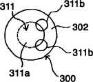
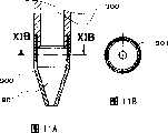
图1IA是本发明第9实施例涡旋式压缩机的旋转轴下部纵剖面图,图11B是图11A的XIB-XIB剖面图。Fig. 1IA is a longitudinal sectional view of the lower portion of the rotating shaft of a scroll compressor according to a ninth embodiment of the present invention, and Fig. 11B is a sectional view along line XIB-XIB of Fig. 11A.
具体实施方式Detailed ways
以下,参照附图说明本发明的多个实施例。各实施例的附图上的相同符号表示相同物体或相当于该物体的部件。Hereinafter, several embodiments of the present invention will be described with reference to the drawings. The same symbols in the drawings of the respective embodiments represent the same objects or members corresponding to the objects.
参照图1、图2A及图2B,说明本发明第1实施例的涡旋式压缩机。图1是本发明第1实施例的涡旋式压缩机的纵剖面图,图2A是图1的涡旋式压缩机的旋转轴下部及泵部的纵剖面图,图2B是图2A的IIB-IIB剖面图。Referring to Fig. 1, Fig. 2A and Fig. 2B, a scroll compressor according to a first embodiment of the present invention will be described. Fig. 1 is a longitudinal sectional view of a scroll compressor according to the first embodiment of the present invention, Fig. 2A is a longitudinal sectional view of the lower part of the rotating shaft and a pump part of the scroll compressor of Fig. 1, and Fig. 2B is IIB of Fig. 2A - Sectional view of the IIB.
涡旋式压缩机1,是将压缩机构部2及驱动部3收纳于密闭容器700内的结构。在本实施例中,从上顺序配置了压缩机构部2、驱动部3及油槽703,是通过旋转轴300将压缩机构部2与驱动部3连结的立式涡旋式压缩机。The scroll compressor 1 has a structure in which the
压缩机构部2,以固定涡盘100、旋转涡盘200及机架400为基本要素而构成。机架400被固定于密闭容器700上,并构成配置有滚动轴承401的部件。固定涡盘100,其以台板101、涡旋状涡圈102、吸入口103及排出口104为基本结构部分而构成,并由螺栓405固定在机架400上。涡圈102与台板101一侧垂直地竖直设置。旋转涡盘200,以台板201、涡旋状涡圈202、轴毂203及背压孔为基本结构部分而构成。涡圈202与台板201一侧垂直地竖直设置。轴毂203垂直凸出地形成于台板201的另一侧(涡圈相反侧)。旋转涡盘200,是将以铸铁或铝等为材料的铸件加工成各构成部分而形成。The
使固定涡盘100与旋转涡盘200噛合所构成的压缩室130,利用旋转涡盘200的旋转运动进行减少其容积的压缩动作。在该压缩动作中,随着旋转涡盘200的旋转运动,使动作流体经过吸入管711及吸入口103而吸入压缩室130,被吸入的工作流体经过压缩行程从固定涡盘100的排出口104排到密闭容器700内,再经过排出管701从密闭容器700排出。因此,密闭容器700内的空间保持着排出压力。The
密闭容器700,具有上封盖710及下封盖720。上封盖710及下封盖720与密闭容器的中央圆筒部嵌合并覆盖其外侧,用焊炬从斜下方及斜上方将其嵌合部进行加热焊接。密闭容器700的底面上安装了脚部721。The
另外,在密闭容器700的侧面上设有密封端子702及端子罩703,以向电动机600供电。密封端子702,其贯通并被设于密闭容器700上,位于定子601的末端线圈与机架400之间且面对平衡配重407的最大外径部407a。In addition, a sealed
另外,在与密封端子702相反侧的密闭容器700的侧面上,设有贯通密闭容器700的排出管701,排出管701位于定子601的末端线圈与机架400之间且面对平衡配重407的最大外径部407a。In addition, on the side of the
旋转驱动旋转涡盘200的驱动部3,以定子601及转子602构成的电动机600、旋转轴300、作为旋转涡盘200自转阻止机构的主要部件的欧式联轴器500、机架400、滚动轴承401、803、轴毂203为基本要素构成。The driving
旋转轴300,是整体具有主轴部302、曲柄销301及副轴承支撑部303的结构。滚动轴承401、803,构成能灵活旋转地与旋转轴300的主轴部302及副轴承支撑部303配合的旋转轴支撑部。轴毂203,被形成在旋转涡盘200上,能向作为旋转轴方向的轴向移动、并能灵活旋转地与旋转轴300的曲柄销301配合。The
滚动轴承401,被配置于电动机600的上侧,构成副轴承部800主要部分的滚动轴承(副轴承)803,被配置在电动机600的下侧。在被固定于密闭容器700上的下机架801上,由螺栓805固定着外壳802。从上方将滚动轴承803插入外壳802,并从其上方再安装外壳盖804。The rolling
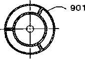
泵部900,被设在旋转轴300的下端部。泵部900,由泵部件901及泵叶片902构成。泵部件901,具有被安装在旋转轴300下端部的部分、及从该部分向下方延伸且流路截面变小的部分构成。换言之,泵部件901,由上部圆筒部901a及下部圆锥部901b构成。上部圆筒部901a的上端部,嵌合并固定在旋转轴300下端部。在泵部件901的下部圆锥部901b的下端部,设有开口。泵叶片902,具有与泵部件901内面形状相同的外形,并被压入泵部件901内。即,泵叶片902被配置为从泵部件901内的上部延伸到下端开口部。The
利用与旋转轴300一起旋转的泵部900内的离心效果,从泵部下端吸入储存于密闭容器700底部油槽730内的油,并向形成于旋转轴300内的油路311供油。The oil stored in the
旋转轴300的油路311,是具有从副轴承支撑部303的下端延伸到主轴部302下部的第1油路311a、及与该第1油路311a连通并延伸到曲柄销301上端的第2油路311b的结构。第1油路311a与旋转轴300同轴。第2油路311b,其直径比第1油路311a小、并具有位置外方的通路部分,而且在曲柄销301的平面范围内形成了多个(本实施例中是两个)。第2油路311b与第1油路311a的圆周边缘部交叉形成,并能沿轴向较长地连通。并且,第2油路311b,被配置在与旋转轴300中心偏心的位置,该偏心能起到第2离心泵的作用。The
欧式联轴器500,被设在旋转涡盘200的台板201的背面。形成于欧式联轴器500上的垂直交叉的2组键部分的1组,滑动于形成在机架400上的作为欧式联轴器500承受部的键槽内,另外的1组滑动于形成在涡旋状涡圈202背面的键槽内。因此,旋转涡盘200,在与涡旋状涡圈202的直立设置方向的轴线方向垂直的平面内,不能自转地相对于固定涡盘100做旋转运动。The
压缩机构部2,当曲柄销301通过与电动机600连结的旋转轴300的旋转而产生偏心旋转时,旋转涡盘200,其因欧式联轴器500的自转防止机构不能自转、而相对于固定涡盘100进行旋转运动,使气体通过吸入管711及吸入口103吸入由涡旋状涡圈102及202形成的压缩室130内。利用旋转涡盘200的旋转运动,压缩室130一边向中央部移动一边减小容积并对气体进行压缩,由排出口104将压缩气体排到排出室。被排到排出室的气体,在循环于压缩机构部3及电动机600的周围以后,从排出管701向压缩机外排出。In the
另外,在旋转涡盘200的台板201上,设有将压缩室130与旋转背面的背压室411连通的背压孔,以将背压室411的压力保持在吸入压力与排出压力之间的压力(中间压力)。形成于旋转涡盘200背面侧的背压室411,是以旋转涡盘200、机架400及固定涡盘100围绕而形成的空间。因此,机架400也兼作形成背压室411的部件。In addition, on the
被设在机架400的槽409上的密封环410,可防止排出气体流入背压室411。旋转涡盘200,被背压室411的中间压力及作用于密封环410内侧的排出压力的合力压在固定涡盘100上。The sealing
此时,密封环410的内径,比滚动轴承401的外径小。由于可以采用这样的结构,所以在本实施例中,能将滚动轴承401从机架400的旋转驱动机构侧插入机架400,并能用机架盖403将所插入的滚动轴承401固定。在机架盖403上设有滑动轴承402。机架盖403与机架400分别成形。机架盖403被螺栓406固定在机架400上。之所以这样用螺栓固定,是因为能可靠地密封机架盖403与机架400的间隙的缘故,因此,能抑制来自供油通路的漏油。另外,机架盖403,由插入机架400内侧且推压滚动轴承401的部分、及与机架400的旋转驱动机构侧端面靠接且被固定其上的部分构成。At this time, the inner diameter of the
平衡配重407,被设在旋转轴300的、自滚动轴承401靠近电动机侧。在本实施例中,平衡配重407与旋转轴300分别形成并压入固定在旋转轴300上,但也可以将平衡配重407设计为与旋转轴300形成为整体。平衡配重407的最大外径部407a,被设计为向定子601的线圈末端的端面侧凸出,且直径比线圈末端的内径大。The
金属制的平衡配重罩404,由底壁和侧壁构成为筒状,并被设计为能覆盖平衡配重407最大外径部407a的外圆周。该平衡配重罩404与固定机架盖403一起被螺栓406固定在机架400上。平衡配重罩404的侧壁,被设在排出管701与平衡配重407最大外径部407a之间,并且被设在密封端子702与平衡配重407最大外径部407a之间。The metal
这样,平衡配重罩404,封闭了机架400与定子601的末端线圈端面之间的空间。即,平衡配重407最大外径部407a的外方空间,实际上被平衡配重罩404封闭。In this way, the
以下,说明供油通路。当旋转轴300旋转时,利用泵部900将油槽730内的油送往旋转轴内的油路311。被送到油路311中的油的一部分,通过横孔312流到作为滚动轴承的副轴承803,然后返回油槽730。通过油路311而到达曲柄销301上部的油,通过旋转轴承210,再流向滚动轴承401。润滑了滚动轴承401的油,几乎都通过排油管408返回油槽730。润滑了滚动轴承401的油的一部分,通过机架盖403与旋转轴300之间的间隙到达平衡配重407,并通过平衡配重407而飞溅,但可附着于平衡配重罩404的侧壁404b的内面上而被回收,向电动机600流下并返回油槽730。Hereinafter, the oil supply passage will be described. When the
另外,在旋转涡盘200的轴毂203的端面上,设有供油油兜205,通过旋转涡盘200的旋转运动,供油油兜205往复于密封环410的外侧及内侧,并将旋转轴承201与滚动轴承401之间的油的一部分运送到背压室411。被运送的油在对欧式联轴器500供油后,对固定涡盘的镜板面105与旋转涡盘200的台板201的滑动面供油。In addition, on the end surface of the
被运送到背压室411的油,通过背压孔,或通过镜板滑动面的微小间隙流入压缩室130。流入压缩室130的油与被压缩的制冷剂气体一起从排出口104排出,并在密闭容器700内与制冷剂气体分离而返回油槽730。The oil delivered to the
根据本实施例,由于旋转轴300整体具有被固定在电动机600的转子602上的主轴部302、被偏心设在该主轴部302的上端部且与压缩机构部2连结的曲柄销301、被设在主轴部302下端部且由副轴承803支撑的小直径的副轴承支撑部303,所以能确保旋转轴300必要的强度,并且能用副轴承803高精度地支承副轴承支撑部303。According to this embodiment, since the
另外,根据本实施例,由于是离心式泵部,所以与容积式泵部相比可以降低价格。并且,由于泵叶片902延伸到泵部件901的下端部,所以即使油槽730的油量较少也能通过配置到泵部件901下端的离心泵叶片902的效果充分发挥供油能力,能提供高可靠性的泵机构。In addition, according to this embodiment, since it is a centrifugal pump unit, it is possible to reduce the price compared with a positive displacement pump unit. Moreover, since the
并且,根据本实施例,由于旋转轴300的油路311,是具有从副轴承支撑部303的下端延伸到主轴部302下部的第1油路311a、及与该第1油路311a连通并且延伸到曲柄销301上端的第2油路311b的结构,第2油路311b,其直径比第1油路311a小且具有位于外方的通路部分,并且在曲柄销301的平面范围内形成了多个,所以既能满足上述旋转轴300结构,又可以在旋转轴300的有限的截面积内确保大离心力及大流路截面积。因此,第2油路311b具有作为第2离心泵的功能,能以廉价的结构充分确保供油量,并能成为可靠性优越的涡旋式压缩机。And, according to this embodiment, since the
以下,参照图3A~图11B说明本发明的第2~第9实施例。这些第2~第9实施例,有着如下所述的与第1实施例不同的结构,其他各点与第1实施例基本相同。Hereinafter, second to ninth embodiments of the present invention will be described with reference to FIGS. 3A to 11B . These second to ninth embodiments have different structures from the first embodiment as described below, and are basically the same as the first embodiment in other points.
参照图3A~图4说明第2实施例。图3A~3C是第2实施例的涡旋式压缩机所用泵部件的说明图,图3A是俯视图,图3B是主视图,图3C是侧视图。图4是第2实施例泵部件的供油特性曲线图。A second embodiment will be described with reference to FIGS. 3A to 4 . 3A to 3C are explanatory views of a pump member used in a scroll compressor according to a second embodiment, wherein FIG. 3A is a plan view, FIG. 3B is a front view, and FIG. 3C is a side view. Fig. 4 is a graph showing the oil supply characteristics of the pump unit of the second embodiment.
在该第2实施例中,构成泵部900的部件只是泵部件901,不具有第1实施例的泵叶片902。泵部件901,以圆锥形状为基本形状,与旋转轴300的结合部是圆筒状、与旋转轴300相反侧是扁平形状,并用圆滑的曲线形成结合部与相反侧端面的扁平形状。In this second embodiment, the member constituting the
根据该第2实施例,由于离心效果整体地作用于泵部件901的扁平形状内的截面部,所以加大了对存在于泵部件901内油的供油能力,且能不受油粘度的影响而稳定地供油。即,当油温上升且油粘度下降时,用简单的圆锥形状的泵部件901,则会如图4的特性(b)所示使供油量急剧地减少,但用该第2实施例的扁平形状泵部件901,则会如图4的特性(a)所示,能获得供油量变化小且稳定的供油量。According to this second embodiment, since the centrifugal effect acts on the cross-sectional portion in the flat shape of the
另外,根据该第2实施例,由于能如上所述地获得稳定的供油量,所以能以一个部件构成泵部900,因此是廉价的结构。In addition, according to the second embodiment, since the stable oil supply amount can be obtained as described above, the
以下,参照图5A~图5C说明第3实施例。图5A~图5C是本发明第3实施例的涡旋式压缩机所用泵部件的说明图,图5A是俯视图,图5B是主视图,图5C是侧视图。Hereinafter, a third embodiment will be described with reference to FIGS. 5A to 5C . 5A to 5C are explanatory views of a pump unit used in a scroll compressor according to a third embodiment of the present invention. FIG. 5A is a plan view, FIG. 5B is a front view, and FIG. 5C is a side view.
在该第3实施例中,泵部件901,以圆筒形状为基本形状,与旋转轴300的结合部是圆筒状、与旋转轴300相反侧是扁平形状。根据该第3实施例的泵部件901,由于其基本形状是圆筒形状,所以能成为更廉价的结构。In the third embodiment, the
以下,参照图6A~图6C说明第4实施例。图6A~图6C是本发明第4实施例的涡旋式压缩机的泵部的说明图,图6A是纵剖面图,图6B是其泵叶片单体的侧视图,图6C是图6A的VIC-VIC剖面图。Hereinafter, a fourth embodiment will be described with reference to FIGS. 6A to 6C . 6A to 6C are explanatory views of the pump portion of the scroll compressor according to the fourth embodiment of the present invention, FIG. 6A is a longitudinal sectional view, FIG. 6B is a side view of the pump vane unit, and FIG. Sectional view of VIC-VIC.
在该第4实施例中,在泵部件901内设有凸起901c。被配置在泵部件901内且与泵部件901一起旋转的泵叶片902,受到由旋转轴300而被驱动的泵部件901内流体惯性力,并受到与旋转轴300旋转方向相反的力。为了支撑作用于泵叶片902上的、与旋转方向相反的力,在泵部件901内设置了凸起901c,并作为泵叶片902的档块。由于在泵部件901内设置了凸起901c,因此可以可靠地支撑泵叶片902,并能以简单、廉价的的结构提高泵部900的可靠性。并且,泵叶片902,其下端延伸到泵部件901的圆筒部分为止,且上部延伸到油路311内。In this fourth embodiment, a protrusion 901c is provided in the
以下,参照图7A~图7C说明第5实施例。图7A~图7C是本发明第5实施例的涡旋式压缩机的泵部说明图。图7A是泵部纵剖面图,图7B是泵叶片单体的侧视图,图7C是图7A的VIIC-VIIC剖面图。Hereinafter, a fifth embodiment will be described with reference to FIGS. 7A to 7C . 7A to 7C are explanatory views of a pump section of a scroll compressor according to a fifth embodiment of the present invention. Fig. 7A is a longitudinal sectional view of the pump portion, Fig. 7B is a side view of the pump vane unit, and Fig. 7C is a sectional view taken along line VIIC-VIIC of Fig. 7A.
在该第5实施例中,在泵部件901内设有一对凸起901c。在相面对的两处设有该一对凸起901c。泵叶片902,其两侧端部被分别夹持在一对凸起901c之间。因此,无论对应于旋转轴300的正转、反转,都能可靠地支撑泵叶片902,并可以供油。In this fifth embodiment, a pair of projections 901c are provided inside the
以下,参照图8A~图8C说明第6实施例。图8A~图8C是本发明第6实施例的涡旋式压缩机的泵部的说明图,图8A是泵部纵剖面图,图8B是泵叶片单体的侧视图,图8C是图8A的VIIIC-VIIIC剖面图。Hereinafter, a sixth embodiment will be described with reference to FIGS. 8A to 8C . 8A to 8C are explanatory views of the pump portion of the scroll compressor according to the sixth embodiment of the present invention, FIG. 8A is a longitudinal sectional view of the pump portion, FIG. 8B is a side view of the pump vane unit, and FIG. 8C is a view of FIG. 8A. Sectional view of VIIIC-VIIIC.
该第6实施例,与该第5实施例比较,其泵叶片902延伸到泵部件901的下端部这一点不同,其他的都相同,根据该第6实施例,与第1实施例一样,即使油槽730的油量变少也能利用配置到泵部件901下端部离心泵叶片902的效果,充分发挥供油能力,所以能获得高可靠性的泵机构。The sixth embodiment is different from the fifth embodiment in that the
以下,参照图9A~图9C说明第7实施例。图9A~图9C是本发明第7实施例涡旋式压缩机的泵部说明图。图9A是泵部纵剖面图,图9B是泵叶片单体的侧视图,图9C是图9A的IXC-IXC剖面图。Hereinafter, a seventh embodiment will be described with reference to FIGS. 9A to 9C . 9A to 9C are explanatory views of a pump section of a scroll compressor according to a seventh embodiment of the present invention. Fig. 9A is a longitudinal sectional view of the pump portion, Fig. 9B is a side view of a single pump vane, and Fig. 9C is a sectional view along line IXC-IXC of Fig. 9A.
该第7实施例,与该第6实施例比较,在泵部件901与旋转轴300的结合部相反侧的形状被形成为球面这一点不同,其他都相同。根据该第7实施例,由于相对于圆锥形状、圆筒形状,其泵部件900内壁的、相对于旋转轴300轴心的倾斜较大,所以加大了离心泵效果,能获得稳定的供油能力,所以能提供高可靠性的泵机构。The seventh embodiment differs from the sixth embodiment in that the shape of the
以下,参照图10A及图10B说明第8实施例。图10A及图10B是本发明第8实施例的涡旋式压缩机的旋转轴下部说明图。图10A是旋转轴下部纵剖面图,图10B是图10A的XB-XB剖面图。Hereinafter, an eighth embodiment will be described with reference to FIGS. 10A and 10B. 10A and 10B are explanatory views of the lower part of the rotating shaft of the scroll compressor according to the eighth embodiment of the present invention. Fig. 10A is a longitudinal sectional view of the lower part of the rotating shaft, and Fig. 10B is a sectional view along XB-XB of Fig. 10A.
该第8实施例,将泵部件901的外圆周部分形成双层圆筒状。泵部件901的外侧空间面向副轴承部800的下面开口。泵部件901的内侧空间与第1实施例相同。In the eighth embodiment, the outer peripheral portion of the
根据该第8实施例,被配置于泵部件901圆周的圆筒状部件,发挥了第3离心泵效果。从第3离心泵上端排出的油,被用于润滑配置于副轴承部800的副轴承803。因此,能稳定地向副轴承803供油,并且由于向泵部件901供给的油是别的系统的供油通路,所以能以简单设计而获得高可靠性的供油结构。According to the eighth embodiment, the cylindrical member disposed on the circumference of the
以下,参照图11A及图11B说明第9实施例。图11A及图11B是本发明第9实施例的涡旋式压缩机的旋转轴下部说明图。图11A是旋转轴下部纵剖面图,图11B是图11A的XIC-XIC剖面图。Hereinafter, a ninth embodiment will be described with reference to FIGS. 11A and 11B . 11A and 11B are explanatory views of the lower part of the rotating shaft of the scroll compressor according to the ninth embodiment of the present invention. Fig. 11A is a longitudinal sectional view of the lower part of the rotating shaft, and Fig. 11B is a sectional view along XIC-XIC of Fig. 11A.
该第9实施例,将泵部件901与旋转轴300的结合机构形成为具有与旋转轴300的旋转方向相同的螺纹牙的卷绕方向的螺纹。由于泵部件901,接受与旋转轴300旋转方向相反方向的力,所以利用作用于泵部件901的、与旋转轴300旋转方向相反方向的力,结合机构的螺纹受到朝拧紧方向的力,所以能获得泵部件901不会从旋转轴300脱落且高可靠性的泵机构。In this ninth embodiment, the coupling mechanism between the
以上所述的是对于实施例记载,但本发明不局限于此,在本发明的精神及发明的范围内可以进行各种变更及修正。The above description is for the embodiments, but the present invention is not limited thereto, and various changes and corrections can be made within the spirit and scope of the present invention.
Claims (10)
Translated fromChineseApplications Claiming Priority (2)
| Application Number | Priority Date | Filing Date | Title |
|---|---|---|---|
| JP2003379436AJP2005140066A (en) | 2003-11-10 | 2003-11-10 | Fluid compressor |
| JP2003379436 | 2003-11-10 |
Publications (2)
| Publication Number | Publication Date |
|---|---|
| CN1616828Atrue CN1616828A (en) | 2005-05-18 |
| CN100376800C CN100376800C (en) | 2008-03-26 |
Family
ID=34689487
Family Applications (1)
| Application Number | Title | Priority Date | Filing Date |
|---|---|---|---|
| CNB2004100905005AExpired - Fee RelatedCN100376800C (en) | 2003-11-10 | 2004-11-10 | fluid compressor |
Country Status (4)
| Country | Link |
|---|---|
| US (1) | US20050180871A1 (en) |
| JP (1) | JP2005140066A (en) |
| KR (1) | KR100657038B1 (en) |
| CN (1) | CN100376800C (en) |
Cited By (5)
| Publication number | Priority date | Publication date | Assignee | Title |
|---|---|---|---|---|
| CN102102671B (en)* | 2009-12-17 | 2012-11-07 | 广东美芝制冷设备有限公司 | Oil supply device of compressor and application thereof |
| CN105190045A (en)* | 2013-06-05 | 2015-12-23 | Lg电子株式会社 | Scroll compressor |
| CN109923309A (en)* | 2016-12-27 | 2019-06-21 | 尼代克全球应用德国有限公司 | Lubricant receiving portion for refrigerant compressor and refrigerant compressor |
| CN112460028A (en)* | 2020-12-03 | 2021-03-09 | 珠海格力节能环保制冷技术研究中心有限公司 | Compressor and air conditioner |
| CN115962131A (en)* | 2023-01-05 | 2023-04-14 | 珠海格力节能环保制冷技术研究中心有限公司 | Suction structures, pump body components and compressors |
Families Citing this family (8)
| Publication number | Priority date | Publication date | Assignee | Title |
|---|---|---|---|---|
| JP4696153B2 (en)* | 2008-12-15 | 2011-06-08 | 日立アプライアンス株式会社 | Rotary compressor |
| BRPI0902430A2 (en)* | 2009-07-24 | 2011-04-05 | Whirlpool Sa | airtight compressor |
| JP5511972B2 (en)* | 2010-10-06 | 2014-06-04 | 株式会社アルバック | Eccentric turning drive |
| US9938977B2 (en)* | 2015-02-03 | 2018-04-10 | Emerson Climate Technologies, Inc. | Compressor with oil pump assembly |
| EP3001039B1 (en)* | 2015-09-11 | 2019-06-19 | Pfeiffer Vacuum Gmbh | Vacuum pump |
| CN106949060B (en)* | 2017-04-19 | 2019-03-05 | 西安庆安制冷设备股份有限公司 | A kind of rotor-type compressor oil suction structure and its design method |
| TR201712410A2 (en)* | 2017-08-21 | 2019-03-21 | Arcelik As | A COMPRESSOR WITH INCREASED LUBRICATION PERFORMANCE |
| KR102422698B1 (en)* | 2020-11-06 | 2022-07-20 | 엘지전자 주식회사 | Hermetic compressor |
Family Cites Families (18)
| Publication number | Priority date | Publication date | Assignee | Title |
|---|---|---|---|---|
| US2743673A (en)* | 1950-08-01 | 1956-05-01 | American Crucible Products Com | Pump-motor unit |
| US2766027A (en)* | 1953-10-21 | 1956-10-09 | Paul A Herr | Apparatus for controlling humidity conditions in air |
| US4140441A (en)* | 1977-04-11 | 1979-02-20 | Patterson Williams G | Turbomolecular pump lubrication system |
| US4488855A (en)* | 1982-12-27 | 1984-12-18 | The Trane Company | Main bearing lubrication system for scroll machine |
| JPS60206989A (en)* | 1984-03-30 | 1985-10-18 | Mitsubishi Electric Corp | Scroll type fluid machine |
| KR870002381A (en)* | 1985-08-23 | 1987-03-31 | 미다 가쓰시게 | Shroul Compressor |
| JPH0647991B2 (en)* | 1986-05-15 | 1994-06-22 | 三菱電機株式会社 | Scroll compressor |
| US4850819A (en)* | 1987-11-20 | 1989-07-25 | Copeland Corporation | Motor compressor bearing assembly |
| JPH0660636B2 (en)* | 1989-08-28 | 1994-08-10 | 株式会社日立製作所 | Scroll compressor |
| US5533875A (en)* | 1995-04-07 | 1996-07-09 | American Standard Inc. | Scroll compressor having a frame and open sleeve for controlling gas and lubricant flow |
| JP2915852B2 (en)* | 1996-09-06 | 1999-07-05 | 三菱重工業株式会社 | Scroll compressor |
| JP2000179460A (en)* | 1998-12-15 | 2000-06-27 | Denso Corp | Compressor |
| US6457561B1 (en)* | 2000-05-25 | 2002-10-01 | Bristol Compressors, Inc. | Viscous pumping system |
| JP2001349291A (en)* | 2000-06-08 | 2001-12-21 | Hitachi Ltd | Scroll compressor |
| US6484846B1 (en)* | 2000-10-25 | 2002-11-26 | White Consolidated Industries, Inc. | Compressor oil pick-up tube |
| KR100422367B1 (en)* | 2001-07-14 | 2004-03-12 | 삼성광주전자 주식회사 | Oil pickup apparatus for Hermetic compressor |
| EP1456538B1 (en)* | 2001-12-17 | 2008-10-15 | Lg Electronics Inc. | Dual capacity compressor |
| US6752605B2 (en)* | 2002-10-15 | 2004-06-22 | Tecumseh Products Company | Horizontal two stage rotary compressor with a bearing-driven lubrication structure |
- 2003
- 2003-11-10JPJP2003379436Apatent/JP2005140066A/enactivePending
- 2004
- 2004-11-08USUS10/982,927patent/US20050180871A1/ennot_activeAbandoned
- 2004-11-09KRKR1020040090683Apatent/KR100657038B1/ennot_activeExpired - Fee Related
- 2004-11-10CNCNB2004100905005Apatent/CN100376800C/ennot_activeExpired - Fee Related
Cited By (8)
| Publication number | Priority date | Publication date | Assignee | Title |
|---|---|---|---|---|
| CN102102671B (en)* | 2009-12-17 | 2012-11-07 | 广东美芝制冷设备有限公司 | Oil supply device of compressor and application thereof |
| CN105190045A (en)* | 2013-06-05 | 2015-12-23 | Lg电子株式会社 | Scroll compressor |
| CN105190045B (en)* | 2013-06-05 | 2017-04-26 | Lg电子株式会社 | scroll compressor |
| US9689388B2 (en) | 2013-06-05 | 2017-06-27 | Lg Electronics Inc. | Scroll compressor |
| CN109923309A (en)* | 2016-12-27 | 2019-06-21 | 尼代克全球应用德国有限公司 | Lubricant receiving portion for refrigerant compressor and refrigerant compressor |
| CN109923309B (en)* | 2016-12-27 | 2024-03-15 | 思科普有限公司 | Lubricant receptacle for refrigerant compressor and refrigerant compressor |
| CN112460028A (en)* | 2020-12-03 | 2021-03-09 | 珠海格力节能环保制冷技术研究中心有限公司 | Compressor and air conditioner |
| CN115962131A (en)* | 2023-01-05 | 2023-04-14 | 珠海格力节能环保制冷技术研究中心有限公司 | Suction structures, pump body components and compressors |
Also Published As
| Publication number | Publication date |
|---|---|
| KR100657038B1 (en) | 2006-12-12 |
| CN100376800C (en) | 2008-03-26 |
| JP2005140066A (en) | 2005-06-02 |
| KR20050045850A (en) | 2005-05-17 |
| US20050180871A1 (en) | 2005-08-18 |
Similar Documents
| Publication | Publication Date | Title |
|---|---|---|
| CN1150378C (en) | Scroll compressor | |
| JP5260608B2 (en) | Scroll compressor | |
| CN1670335A (en) | Scroll machines with stepped guide sleeves | |
| CN1598319A (en) | Scroll compressor | |
| CN1616828A (en) | Fluid compressor | |
| CN1037991C (en) | scroll compressor | |
| CN1344865A (en) | Positive displacement fluid machinery | |
| JP4939884B2 (en) | Fluid compressor | |
| KR20180090324A (en) | Rotary compressor | |
| WO2016189738A1 (en) | Scroll compressor | |
| CN100567741C (en) | Internal gear compressor | |
| JP2015055221A (en) | Scroll compressor and air conditioner equipped with the same | |
| JP2006090180A (en) | Hermetic compressor | |
| CN1080389C (en) | fluid compressor | |
| CN1083944C (en) | Fluid machinery | |
| JP2005140064A (en) | Electric compressor | |
| JP2004293530A (en) | Fluid compressor | |
| CN113494457B (en) | Counterweight assembly of scroll compressor and scroll compressor | |
| JP4243805B2 (en) | Fluid compressor | |
| JP3876670B2 (en) | Manufacturing method of hermetic compressor | |
| KR100299589B1 (en) | Fluid appatus | |
| JP4797548B2 (en) | Hermetic electric compressor | |
| CN100455811C (en) | Oil supply for rotary compressors | |
| JP4663293B2 (en) | Compressor | |
| JP5520762B2 (en) | Scroll compressor, electric compressor |
Legal Events
| Date | Code | Title | Description |
|---|---|---|---|
| C06 | Publication | ||
| PB01 | Publication | ||
| C10 | Entry into substantive examination | ||
| SE01 | Entry into force of request for substantive examination | ||
| C14 | Grant of patent or utility model | ||
| GR01 | Patent grant | ||
| C56 | Change in the name or address of the patentee | ||
| CP01 | Change in the name or title of a patent holder | Address after:Tokyo, Japan Patentee after:Hitachi Appliances, Inc. Address before:Tokyo, Japan Patentee before:Hitachi Appliances, Inc. | |
| C41 | Transfer of patent application or patent right or utility model | ||
| TR01 | Transfer of patent right | Effective date of registration:20160901 Address after:Hongkong aoteng Plaza No. 8 Chinese Kowloon Linze street 12 floor Patentee after:Johnson Controls Hitachi air conditioning technology (Hong Kong) Co.,Ltd. Address before:Tokyo, Japan Patentee before:Hitachi Appliances, Inc. | |
| TR01 | Transfer of patent right | Effective date of registration:20180703 Address after:Tokyo, Japan Patentee after:HITACHI-JOHNSON CONTROLS AIR CONDITIONING, Inc. Address before:Hongkong aoteng Plaza No. 8 Chinese Kowloon Linze street 12 floor Patentee before:Johnson Controls Hitachi air conditioning technology (Hong Kong) Co.,Ltd. | |
| TR01 | Transfer of patent right | ||
| CF01 | Termination of patent right due to non-payment of annual fee | Granted publication date:20080326 Termination date:20211110 | |
| CF01 | Termination of patent right due to non-payment of annual fee |